ANNEX
The Annex to Regulation (EU) 2019/773 is amended as follows:
(1)point 1.3 is replaced by the following:
‘
1.3. Content
In accordance with Article 4(3) of Directive (EU) 2016/797, this TSI lays down the essential requirements for the ‘operation and traffic management’ subsystem and establishes the fundamental operating principles and common operating rules to the Union railway system. Furthermore, it establishes the interface requirements between infrastructure managers and railway undertakings.’;
(2)point 2 is replaced by the following:
‘2. DESCRIPTION OF SCOPE
This TSI applies to the Union rail system, which includes TSI conform and non-TSI conform vehicles and fixed installations.
This TSI relates to processes and procedures, as well as to physical elements of vehicles and fixed installations that are important for their operational function in the context of this TSI.
The railway undertaking and the infrastructure manager shall ensure that all requirements of this TSI become a relevant part of railway undertaking’s and infrastructure manager’s safety management system (‘SMS’) as required by Directive (EU) 2016/798.’;
(3)in point 3.2, the first and the second paragraphs are deleted;
(4)point 4.1 is replaced by the following:
‘
4.1. Introduction
In accordance with Directive 2012/34/EU of the European Parliament and of the Council*, it is the overall responsibility of the infrastructure manager to provide all the appropriate parameters and characteristics of the infrastructure which shall be used by the railway undertaking to check the compatibility of its trains to run on its network, taking into account the geographic particularities of individual lines and the functional or technical specifications set out in this section.
The fundamental operational principles and common operational rules applicable to the Union rail network are defined in Appendix B.
_________
* Directive 2012/34/EU of the European Parliament and of the Council of 21 November 2012 establishing a single European railway area (OJ L 343, 14.12.2012, p. 32).’;
(5)point 4.2 is replaced by the following:
‘
4.2. Functional and technical specifications of the subsystem
The functional and technical specifications of the ‘operation and traffic management’ subsystem define the specifications to ensure safe operation, system reliability and availability and operating efficiency of the Union rail system, with focus in particular on specifications relating to:
–Safety-critical staff,
–trains,
–train operations,
–ERTMS based harmonised operation.’;
(6)point 4.2.1.1 is replaced by the following:
‘
4.2.1.1. General requirements
Safety-critical staff contributes to the safe operation of the Union rail system by performing safety-critical tasks in RUs and IMs; their tasks and functions are defined in their Safety Management Systems, in accordance with Annexes I and II to Commission Delegated Regulation (EU) 2018/762*. Moreover:
–Directive 2007/59/EC of the European Parliament and of the Council** defines training, fitness and certification requriements for train drivers;
–Appendix F of this Annex defines minimum elements relevant to professional qualification applicable to staff other than the train driver ‘accompanying trains’;
–Appendix G of this Annex defines minimum elements relevant to professional qualification applicable to staff ‘preparing trains’;
–the Safety Managemnt System has to define the requirements for other staff that undertakes the safety-critical tasks.
__________
__________
*
Commission Delegated Regulation (EU) 2018/762 of 8 March 2018 establishing common safety methods on safety management system requirements pursuant to Directive (EU) 2016/798 of the European Parliament and of the Council and repealing Commission Regulations (EU) No 1158/2010 and (EU) No 1169/2010 (OJ L 129, 25.5.2018, p. 26).
**
Directive 2007/59/EC of the European Parliament and of the Council of 23 October 2007 on the certification of train drivers operating locomotives and trains on the railway system in the Community (OJ L 315, 3.12.2007, p. 51).’;
(7)point 4.2.1.2 is replaced by the following:
‘4.2.1.2. Documentation for drivers
The railway undertaking operating the train shall supply the train driver with a ʻDriver’s Rule Book’ and a ‘Route Book’, containing at least all the information necessary for train operations. This must cover normal, degraded and emergency situations, as well as the information on routes and rolling stock, for which the driver is tasked to operate.
The ‘Driver’s Rule Book’ and the ‘Route Book’ must be available in electronic format by 16 June 2024.
The railway undertaking must ensure that train drivers were trained and certified according to this documentation, and that their knowledge is updated in accordance with route books and rule books and their latest modifications.
Documentation for drivers shall be consistent across all the lines over which the railway undertaking operates.’;
(8)point 4.2.1.2.1 is replaced by the following:
‘
4.2.1.2.1.
Driver’s Rule Book
The railway undertaking shall provide the driver with a ‘Driver’s Rule Book’ that contains the procedures, methods and operating requirements for drivers to apply on all routes and rolling stock used in situations of normal operation, degraded operation and in emergency situations. The Driver’s Rule Book shall also cover internal railway undertaking operational procedures.
The Driver’s Rule Book shall cover the set of common Union rules and procedures in accordance with Appendices A, B, C and D, complemented by the national rules covering areas defined by Appendix I and RU-IM interface procedures specific to each infrastructure manager.
It shall include procedures covering, as a minimum, the following aspects:
–staff safety and security,
–signalling and control command (class A and class B systems),
–train operation, including degraded mode and related to line characteristics and vehicle characteristics,
–traction and rolling stock, including all information relevant to the operation of the rolling stock during normal and degraded mode (such as trains requiring assistance); such documentation shall also focus on the specific interface with the infrastructure manager’s staff in these cases,
–incidents and accidents, including the reporting scheme, incident or accident management plan and the detailed actions to be taken in the event of an accident or an incident;
–degraded and emergency situations.
The infrastructure manager shall provide the information of the Driver’s Rule Book for which it is responsible and ensure that the content of the documentation provided to the railway undertaking(s) is complete and accurate; the information shall be managed in accordance with Annex II, point 4.4.3 of Delegated Regulation (EU) 2018/762. The driver shall be able to get notification and acknowledge the modification of the Rule Book in real time throught RINF.’
The railway undertaking shall compile the Driver’s Rule Book in a clear, complete and accurate manner, enabling the driver to apply all operational rules.
The railway undertaking must present the Driver’s Rule Book in a clear format for the entire infrastructure over which their drivers will work; the information shall be managed in accordance with Annex I, point 4.4.3 of Delegated Regulation (EU) 2018/762..
It shall have two appendices:
–Appendix 1: Manual of communication procedures;
–Appendix 2: Book of operational instructions in accordance with Appendix C2.
Predefined messages and forms shall at least exist in the ‘operating’ language(s) of infrastructure manager(s).
If the language chosen by the railway undertaking for the Driver’s Rule Book is not the language in which the appropriate information was originally supplied, it is the responsibility of the railway undertaking to arrange for any necessary translation and/or provide explanatory notes in another language.’;
(9)point 4.2.1.2.2 is replaced by the following:
‘
4.2.1.2.2.
Route Book
The ‘Route Book’ shall contain the route information as defined in Appendix D2 that the infrastructure manager is to provide to the railway undertaking through the Register of the Infrastructure defined in Article 49 of Directive (EU) 2016/798 (‘RINF’).
This information shall include relevant information to be taken into account to adapt train operation to line characteristics and vehicle characteristics.
The railway undertaking shall ensure that the route information compiled in the Route Book consists in a description of the lines and the associated lineside equipment for the lines over which the driver will operate and relevant to the driving task.
The format of the Route Book shall be prepared in the same manner for all the infrastructures worked over by the trains of an individual railway undertaking.
The railway undertaking shall be responsible for the complete and correct compilation of the Route Book, using the information supplied by the infrastructure manager(s). The railway undertaking shall ensure that the content of the Route Book is complete and accurate, including when grouping the changes to information contained within the Route Book. The railway undertaking shall ensure the Route Book duly describes operational conditions related to line characteristics and vehicle characteristics.
The infrastructure manager shall ensure that the information provided to the railway undertaking(s) is complete and accurate; the information shall be managed in accordance with Annex I, point 4.4.3 of Delegated Regulation (EU) 2018/762.
The infrastructure manager shall inform the railway undertaking of the changes to the information in the Route Book through RINF whenever such information becomes available, including temporary modifications.
The infrastructure manager shall inform drivers in real time of any changes to the line or relevant lineside equipment that have not been advised as changes to information in the Route Book through RINF whenever such information becomes available, including temporary modifications. The driver shall be able to get notification and acknowledge the modification of the Route Book in real time thruogh RINF.’;
(10)points 4.2.1.2.2.1, 4.2.1.2.2.2 and 4.2.1.2.2.3 are deleted;
(11)point 4.2.1.2.3 is replaced by the following:
‘
4.2.1.2.3. Train running information for drivers
When the railway undertaking provides the drivers with their working plan, they shall provide information necessary for the normal running of the train and as a minimum include:
–the train identification;
–the train running days (if necessary);
–the stopping points and the activities associated with them;
–other timing points;
–the arrival/departure/passing times at each of those points.
Such train running information shall be based and supplment the Rules Book and Route Book information, and provided electronically by 16 June 2024.’;
(12)point 4.2.1.2.4 is deleted;
(13)point 4.2.1.3 is replaced by the following:
‘
4.2.1.3. Documentation for railway undertaking staff other than drivers
In cases where a railway undertaking’s staff (whether on train or otherwise) undertake safety-critical tasks involving a direct interface with the staff, equipment or systems of the infrastructure manager, the railway undertaking shall provide those members of its staff with the rules, procedures, rolling stock and route information appropriate to such tasks. Such information shall be applicable in normal, degraded and emergency operation.
The railway undertaking shall follow the structure, format and content of the Driver’s Rule Book when compiling such information.’;
(14)point 4.2.1.4 is replaced by the following:
‘
4.2.1.4. Documentation for infrastructure manager’s staff authorising train movements
The infrastructure manager shall compile and make available in all its operating language(s) to its staff undertaking safety-critical tasks all the information necessary to ensure safety-related communication between staff authorising the movement of trains and train crews, as set out in Appendix C (documents describing the Communications Principles and Book of Operational Instructions).’;
(15)in point 4.2.2.1.2, the fifth paragraph is replaced by the following:
‘In order to access lines identified in RINF where permissive driving is used, by the dates mentioned below for the harmonisation of the rear-end signal as per Section 4.2.2.1.3.2, the luminous intensity of vehicle headlamps shall be in accordance with the level defined for the full-beam headlamps in point (5) of Section 4.2.7.1.1 of the Annex to Commission Regulation (EU) 1302/2014* (Loc&Pas TSI).
_________
* Commission Regulation (EU) No 1302/2014 of 18 November 2014 concerning a technical specification for interoperability relating to the ‘rolling stock — locomotives and passenger rolling stock’ subsystem of the rail system in the European Union (OJ L 356, 12.12.2014, p. 228).’;
(16)in point 4.2.2.1.3.2, the following text is deleted:
‘Reports:
At the latest by 30 September 2020, the concerned Member States shall deliver to the Commission reports on their use of reflective plates, identifying any serious obstacles to the planned elimination of national rules.’;
(17)point 4.2.2.5.1 is amended as follows:
(a)point B is replaced by the following:
‘(B)The infrastructure manager shall provide the information for route compatibility as defined in Appendix D1 through RINF.
Appendix D1 sets out all the parameters that shall be used in the process of the railway undertaking before the first use of a vehicle or train configuration in order to ensure all vehicles composing a train are compatible with the route(s) the train is planned to operate on including, where appropriate, deviation routes and routes to workshops. Modifications of the route and changes of infrastructure characteristics have to be taken into account. When a parameter of Appendix D1 is harmonised at network(s) level of an area of use, conformity with that parameter may be presumed for any vehicle authorised for that area of use. National rules or additional national requirements for network access in respect of route compatibility are in principle considered incompatible with Appendix D1. The infrastructure manager shall not require additional technical checks for the purpose of route compatibility beyond the list laid down in Appendix D1.
The infrastructure manager shall inform the railway undertaking of the changes on characteristics of the route through RINF whenever such information becomes available.
(b)the following point (D) is added:
‘(D)Specific elements for route compatibility of Combined Transport trains:
–a Combined Transport train not exceeding the loading gauge, and for which the CT code does not exceed the codification of the line, shall be considered as a normal transport;
–a Combined Transport train exceeding the loading gauge, and for which the CT code does not exceed the codification of the line, shall be considered as a transport with specific requirements as referred to in Appendix I. Such requirements shall be universally applicable to all trains in this category and compliance with them shall not need to involve any further authorisation process between the RU and the IM;
–if the CT code exceeds the codification of the line, or if the line is not codified, a specific authorisation (exceptional transport), based on an evaluation of the operational and technical feasibility, shall be issued by the IM.’;
(18)point 4.2.2.5.2 is amended as follows:
(a)point (d) is deleted;
(b)the following second paragraph is inserted:
‘The railway undertaking is responsible for ensuring that all vehicles composing the train including their load are technically fit for the journey to be undertaken and remain so throughout the journey.’;
(19)point 4.2.2.6 is replaced by the following:
‘
4.2.2.6. Train braking
The railway undertaking shall set up and implement braking requirements in accordance with points 4.2.2.6.1 and 4.2.2.6.2 and shall manage them within its safety management system.’;
(20)point 4.2.2.6.2 is amended as follows:
(a)point (1) is replaced by the following:
‘(1)
The infrastructure manager shall provide the railway undertaking with all relevant line characteristics for each route through RINF:
–signalling distances (warning, stopping) containing their inherent safety margins,
–gradients,
–maximum permitted speeds;
–conditions of use of braking systems possibly affecting the infrastructure such as magnetic, regenerative and eddy-current brake.
The infrastructure manager shall ensure that the information provided to the railway undertaking(s) is complete and accurate, and shall inform the railway undertaking of the changes on the line characteristics through RINF whenever such information becomes available.’;
(b)point (3) is replaced by the following:
‘(3)
The railway undertaking shall, in the planning stage, determine the braking regime, the braking capability and corresponding maximum speed of the train taking into account:
(c)the relevant line characteristics as expressed in point (1) and, if available, the information provided by the infrastructure manager in accordance to point (2); and
(d)the rolling stock-related margins derived from reliability and availability of the braking system.
Furthermore, the railway undertaking shall ensure that during operation each train achieves at least the necessary braking performance. In particular the railway undertaking has to set up rules to be used if a train does not reach the necessary braking performance during operation. In this case, the railway undertaking shall immediately inform the infrastructure manager. The infrastructure manager may take appropriate measures to reduce the impact on the overall traffic on its network.’;
(21)point 4.2.2.8 is deleted;
(22)point 4.2.2.9 is replaced by the following:
‘4.2.2.9. Driver Vigilance
The driver’s activity on board shall be monitored to automatically stop the train when a lack of driver's activity is detected. The requirements related to the means to monitor the driver’s onboard activity are specified in the clause set out in point 4.2.9.3.1 of LOC&PAS TSI.’;
(23)point 4.2.3 is replaced by the following:
‘
4.2.3. Specifications relating to train operations, including ERTMS based operation
Fundamental operational principles and common operational rules set out in Appendix B shall apply in addition to this chapter for train operation in the Union rail system.
The ERTMS operational principles and rules specified in Appendix A of this TSI shall apply where ERTMS is deployed.’;
(24)point 4.2.3.1 is replaced by the following:
‘
4.2.3.1. Train planning and timetable
In accordance with Directive 2012/34/EU, the infrastructure manager shall advise what data is required when a train path is requested.
Every train has to follow a timetable, agreed between IM and RU under path allocation process; the IM shall ensure the punctual running of trains and assists in service performance when scheduling the timetable.’;
(25)point 4.2.3.3.1 is replaced by the following:
‘
4.2.3.3.1. Checks and tests before departure
The railway undertaking shall determine the checks and tests to ensure that any departure of train is undertaken safely.’;
(26)in point 4.2.3.4.3, the second indent is replaced by the following:
‘- information to the driver’;
(27)the following point 4.2.3.9 is added:
‘
4.2.3.9. Requirements for signal and lineside marker sighting
Without prejudice of ERTMS operations defined in Appendix A, the driver shall be able to observe signals and lineside markers. Signals and lineside markers as well as all other types of lineside signs that are safety related shall be observable by the driver whenever applicable.
Therefore, signals, lineside markers, signs and information boards shall be designed and positioned in such a consistent way to facilitate this. Issues that shall be taken into account include (see point 4.3.2 of this regulation for reference to CCS TSI):
–that they are suitably sited so that train head lights allow the driver to read the information,
–suitability and intensity of lighting, where required to illuminate the information,
–where retro-reflectivity is employed, the reflective properties of the material used are in compliance with appropriate specifications and the signs are fabricated so that train head lights easily allow the driver to read the information.
Driving cabs shall be designed in such a consistent way that the driver is able to easily see the information displayed to him (see point 4.3.3.1 of this Regulation for reference to Loc&Pas TSI).’;
(28)in point 4.3.2, the table is amended as follows:
(a)the line “Driver’s Rule book Operating rules” is replaced by the following:
‘
|
Driver’s Rule book
Operating rules
ERTMS trackside engineering information relevant to operation
|
4.2.1.2.1
4.4
Appendix D3
|
Operating rules (normal and degraded conditions)
|
4.4
|
’;
(b)the line “Requirements for lineside signal and marker sighting” is replaced by the following:
‘
|
Requirements for lineside signal and marker sighting
|
4.2.2.8
|
track-side control-command and signalling objects
|
4.2.15
4.2.18
|
’;
(29)in point 4.3.3.1, the line ‘Recording of supervision data on-board the train’ is replaced by the following:
‘
|
Recording of monitoring data on-board the train
|
4.2.3.5
Appendix I
|
Recording device
|
4.2.9.6
|
’;
(30)in point 4.4.3, the third and the fourth paragraphs are deleted;
(31)in point 4.6.2.2, point (a), the third indent is replaced by the following:
‘— complete the forms associated with the use of the Book of Operational Instructions’;
(32)in points 4.6.3.1, and 4.6.3.2. the following text is deleted:
‘or Commission Regulations (EU) 1158/2010 and (EU) 1169/2010’;
(33)in point 4.7.1, the first sentence is replaced by the following:
‘Staff specified in point 4.2.1.1 as staff performing safety-critical tasks shall have appropriate fitness to ensure that overall operational and safety standards are met.’;
(34)point 4.8.1 is replaced by the following:
‘
4.8.1. Infrastructure
The requirements for the rail infrastructure related data items with regard to the operation and traffic management subsystem, and which shall be made available to railway undertakings through RINF, are specified in Appendix D.
The infrastructure manager shall inform the railway undertaking of the changes on the infrastructure related data through RINF whenever such information becomesavailable . The infrastructure manager is responsible for the correctness of the data.’;
(35)in point 6.2.1, the second and third paragraphs are replaced by the following:
‘In accordance with Articles 9 and 10 of Directive (EU) 2016/798, railway undertakings and infrastructure managers shall demonstrate compliance with the requirements of this Regulation within their safety management system when applying for any new or amended safety certificate or safety authorisation in accordance with Commission Implementing Regulation (EU) 2018/763*.
The common safety methods for conformity assessment as laid down by Regulation (EU) No 1158/2010 and the common safety methods on safety management system requirements as laid down by Delegated Regulation (EU) 2018/762 require national safety authorities to set up an inspection regime to supervise and monitor compliance with the safety management system in accordance with Commission Delegated Regulation (EU) 2018/761**, including all TSIs. None of the elements contained within this Regulation require separate assessment by a Notified Body.
_________
* Commission Implementing Regulation (EU) 2018/763 of 9 April 2018 establishing practical arrangements for issuing single safety certificates to railway undertakings pursuant to Directive (EU) 2016/798 of the European Parliament and of the Council, and repealing Commission Regulation (EC) No 653/2007 (OJ L 129, 25.5.2018, p. 49).
** Commission Delegated Regulation (EU) 2018/761 of 16 February 2018 establishing common safety methods for supervision by national safety authorities after the issue of a single safety certificate or a safety authorisation pursuant to Directive (EU) 2016/798 of the European Parliament and of the Council and repealing Commission Regulation (EU) No 1077/2012 (OJ L 129, 25.5.2018, p. 16).’;
(36)point 7.1 is replaced by the following:
‘7.1. General rules for implementation
In accordance with Article 9 of Directive (EU) 2016/798 and Article 2 of this Regulation, railway undertakings and infrastructure managers shall ensure compliance with this Regulation under their SMS, established following Delegated Regulation (EU) 2018/762.
7.1.1
Specific transition rules for Appendices A and C
Infrastructure managers and consequently railway undertaking may postpone the implementation of Appendix A and Appendix C of this Annex, following Annex II point 5.1.1. of Delegated Regulation (EU) 2018/762, to 16 December 2025 at the latest, under the condition that they present to the Commission not later than 16 December 2023 an implementation and application plan for the Appendices A and C.
At least by 16 June 2024, each applicant for postponement shall deliver to the Commission and the Agency:
–an implementation plan authorised by the applicant’s management, which sets the delays for the application of the modified operational procedures necessary and, where relevant, the implementation if the respective appropriate IT tools;
–a training plan authorised by the applicant’s management, as defined in point 4.2 of Annexes I and II to Delegated Regulation (EU) 2018/762.’;
(37)point 7.2.2.1 is replaced by the following:
‘7.2.2.1. Permanent specific case (P) Estonia, Latvia, Lithuania, Poland, Hungary and Slovakia
For the implementation of point 4.2.2.1.3.2, freight trains which are operated solely on the 1520 mm gauge network of Estonia, Latvia, Lithuania, Poland, Hungary and Slovakia may use the following train rear end signal.

The reflective disc shall have a diameter of 185 mm with a red circle diameter of 140 mm. Where justified by operating practices, the reflective disc may be replaced with one reflective plate in compliance with Appendix E to WAG TSI.
For the implementation of point 4.2.2.1.3.1, passenger trains which are operated solely on the 1520 mm gauge network of Estonia, Latvia, Lithuania, Poland, Hungary and Slovakia may use 3 steady red lights as train rear end signal following the scheme:

This specific case does not prevent the access of TSI compliant rolling stock to their network.’;
(38)Appendix A is replaced by the following:
‘Appendix A
ERTMS OPERATIONAL PRINCIPLES AND RULES – version 6
1.Intentionally blank
2.Intentionally blank
3.INTRODUCTION
3.1.PURPOSE AND STRUCTURE OF THE DOCUMENT
This Appendix sets out the principles and harmonised rules for the operation of ERTMS.
The structure of each rule is the following:
(i)title,
(ii)when necessary, situations in which the rule applies, presented in a frame, including the applicable ETCS levels; sometimes the situation is described for some specific sub-sections of the rules,
(iii)the rule itself.
When this Appendix refers to ETCS level 1 it applies to both applications, with or without trackside signals, unless otherwise stated.
When this Appendix refers to ETCS level R it applies to both applications, with or without trackside signals, unless otherwise stated.
The European Instructions referenced in this Appendix are listed under Appendix C2 to this TSI.
All language referring to people applies equally to male and female persons.
Part A is intentionally blank.
Part B contains the different ETCS operational train categories.
Part C contains the list of references to non-harmonised rules. In some situations a procedure is not related to ERTMS and therefore depends on non-harmonised rules.
The description of the technical functions for ETCS and GSM-R is contained in the corresponding system requirements specification.
If information displayed on the DMI does not require an action from the driver this information is not contained in the rules.
3.2.SCOPE AND FIELD OF APPLICATION
This Appendix is fully applicable to ETCS On-board units complying with the single set of specifications of Commission Regulation [PO – CCS TSI 2023/XXXX] with an operated system version X.Y up to and including 2.2. It is also applicable to On-board units complying with Set of specifications #2 or Set of specifications #3 and largely applicable to ETCS On-board units complying with Set of specifications #1 of Regulation (EU) 2016/919, provided that the DMI used fulfills the specification ERA_ERTMS_015560.
For On-board units complying with any of the sets of specifications under Regulation (EU) 2016/919, sections of this Appendix referring to Level R(adio) will apply whenever Level 2 or Level 3 is indicated on the DMI.
This Appendix also applies to operational processes of IMs with trackside systems complying with any of the sets of specifications under Regulation (EU) 2016/919, by replacing ‘Level R’ by ‘Level 2’ in all sections.
The scope is the following:
(I)ETCS level 0 application,
(II)ETCS level 1 application whether or not trackside signals or infill are present,
(III)ETCS level R application, whether or not trackside signals are present,
(IV)ETCS transitions between level 0, level 1 and level R applications,
(V)ETCS level NTC application
(VI)ETCS transitions to / from level NTC,
(VII)GSM-R.
Class B systems (even when operated through the ETCS DMI) are out of the scope.
The rules have been developed independently of other control command systems that may be present including where lines are equipped with ETCS level 1 / R.
When ETCS level 1 or ETCS level R are implemented on lines fitted with other control command systems it is necessary to assess the applicability of these rules and if necessary supplement them with non-harmonised rules. This includes those lines fitted with both ETCS level 1 and ETCS level R.
GSM-R voice radio operational rules are applicable on lines equipped with GSM-R independently of the control command system in use. Conversely, ETCS operational rules are applicable on lines equipped with ETCS independently of the voice radio system in use.
The applicability of the rules further depends on the engineering solutions adopted by the ERTMS trackside subsystem. In this context, some rules may not need to apply if the relevant functions are not implemented trackside (e.g. when track conditions are not transmitted or the level crossing procedure is not implemented); yet when a rule needs to apply, it will always do so in the way described in this Appendix .
All actions involving the driver assume his physical presence in the driver’s cab, unless when required to examine a technical failure of the train at standstill, obtain signaller’s instructions through a fixed lineside phone or when requested by the signaller or non-harmonised rules.
Throughout this Appendix , the ETCS On-board unit is assumed to be powered on if not otherwise stated. The desk of the active driving cab is assumed to be open unless otherwise stated.
An End of Authority (EOA) can be physically identified by means of an ETCS Stop Marker or an ETCS Location Marker. The EOA can also be identified by a lineside signal or other marker board with a stop indication. Under certain conditions, an EOA can also be at the train’s front end.
4.REFERENCES, TERMS AND ABBREVIATIONS
4.1.INTENTIONALLY BLANK
4.2.TERMS & ABBREVIATIONS
|
Table 1 : Terms*
|
|
Term
|
Definition
|
|
Acknowledgement
|
Confirmation given by the driver to a request from the ETCS on-board that he/she has received information he/she needs to take into account.
|
|
Applicable speed limit
(in SR)
|
The lowest speed limit of:
- maximum speed for SR,
- maximum train speed,
- timetable / Route Book,
- temporary speed restrictions (transmitted by other means than European Instruction 1, 2, 5, 6, 7 or 8),
- European Instruction.
|
|
Authorisation for ERTMS train movement
|
Permission for a train to move given by means of:
- a trackside signal at proceed aspect or,
- an MA or,
- a European Instruction:
- to start after preparing a movement or,
- to pass EOA or stop signal or,
- to proceed after trip.
|
|
Border crossing
|
Location where trains cross from a railway network in one Member State to a railway network in another Member State.
|
|
De-registration
|
Termination of the temporary relationship between the telephone number and the train running number. This action can be initiated by the user of a GSM-R radio, by automatic systems or by the network authority. The de-registration allows the de-registered train running number to be re-used.
|
|
Driver Machine Interface (DMI)
|
Train device to enable communication between the ETCS on-board and the driver.
|
|
Emergency propelling area
|
Area where propelling movements in RV are allowed.
|
|
Emergency stop order
|
ETCS order braking a train with the maximum brake force until the train is at a standstill.
|
|
End Of Authority (EOA)
|
Location to which an ETCS train is authorised to proceed and where the target speed is zero.
|
|
ETCS Location Marker
|
Harmonised trackside ETCS marker board defined in EN 16494/2015 used to identify a potential EOA, e.g. the end of a block section.
|
|
ETCS on-board
|
The part of ETCS installed on a railway vehicle.
|
|
ETCS Stop Marker
|
Harmonised trackside ETCS marker board defined in EN 16494/2015 used to:
–identify a potential EOA and
–indicate the location where a driver has to stop the train, if running without an MA.
|
|
ETCS operational train category
|
Set of technical and / or operational characteristics of a train to which a specific ETCS speed profile applies.
|
|
Functional number
(GSM-R)
|
Full number used within the functional addressing scheme to identify an end user or a system by function or role rather than by a specific item of radio equipment or user subscription.
The functional number can be divided into two parts:
–functional addressing (process of addressing a call using a specific number, representing the function a user is performing, rather than a number identifying the GSM-R on-board),
–location dependent addressing (process of addressing a particular function – typically a signaller – based on the current location of the user – typically a train).
|
|
GSM-R mode
|
Status of the GSM-R on-board which provides functions for:
–- train movement,
–- or shunting movement.
|
|
GSM-R network
|
Radio network which provides GSM-R functions.
|
|
GSM-R network marker
|
Harmonised trackside GSM-R signal defined in EN 16494/2015 to indicate the network to be selected.
|
|
GSM-R on-board
|
The part of GSM-R installed on a railway vehicle.
|
|
Maximum speed for RV
|
Maximum speed given from the ETCS trackside in RV.
|
|
Maximum speed for SR
|
Maximum speed given from the ETCS trackside in SR.
|
|
Movement Authority (MA)
|
Permission for a train to move to a specific location with supervision of speed.
|
|
Non-stopping area
|
Area defined by the Infrastructure Manager where it may not be safe or suitable to stop a train.
|
|
Override EOA speed
|
Maximum speed when the override EOA function is active.
|
|
Permitted speed
|
Maximum speed at which a train / shunting movement can run without ETCS warning and / or brake intervention.
|
|
Proceed aspect
|
Any signal aspect which permits the driver to pass the signal.
|
|
Propelling
|
Movement of a train where the driver is not in the leading cab of the leading vehicle.
|
|
Radio communication
|
Exchange of information between the ETCS on-board and the RBC / radio infill unit.
|
|
Radio Block Centre (RBC)
|
ETCS trackside centralised unit controlling ETCS train movements in level R.
|
|
Radio hole
|
A pre-defined area where it is not possible to establish a reliable radio communication channel.
|
|
Registration
|
Temporary relationship between the telephone number and the train running number.
|
|
Release speed
|
Maximum speed at which a train is allowed to reach the end of its MA.
|
|
Revocation of MA
|
Withdrawal of a previous given Movement Authority.
|
|
Route Book
|
Description of the lines and the associated line-side equipment for the lines over which the driver will operate and relevant to the driving task.
|
|
Securing
|
Measures to be applied to avoid unintentional movement of railway vehicles.
|
|
Shunting composition
|
A traction unit coupled or not to a set of vehicles and intended to be moved under shunting conditions without train data.
|
|
Shunting movement
|
Way of moving vehicles without train data and controlled by shunting orders.
|
|
Tandem
|
Two or more traction units mechanically and pneumatically coupled but not all remote controlled and where each traction unit not remote controlled requires a driver.
|
|
Temporary speed restriction
|
Reduction of the line speed for a limited period of time.
|
|
Text message
|
Information in writing displayed on the Driver Machine Interface.
|
|
Train data
|
Information which describes the characteristics of a train.
|
|
Train preparer
|
Staff in charge of the preparation of a train.
|
|
Transition
|
Controlled change between the different ETCS levels.
|
|
Transition point
|
Point where a transition between ETCS levels takes place.
|
|
Trip
|
Irrevocable application of the emergency brakes by ETCS until the train / shunting movement is at a standstill.
|
|
Table 2 : Abbreviations *
|
|
Abbreviation
|
|
|
AD
|
Automatic Driving mode
|
|
ATO
|
Automated Train Operation
|
|
DAS
|
Driver Advisory System
|
|
DMI
|
Driver Machine Interface
|
|
EOA
|
End Of Authority
|
|
ERTMS
|
European Rail Traffic Management System
|
|
ETCS
|
European Train Control System
|
|
FS
|
Full Supervision mode
|
|
G
|
Goods train braking mode
|
|
GSM-R
|
Global System for Mobile communication - Railway
|
|
IM
|
Infrastructure Manager
|
|
LS
|
Limited Supervision mode
|
|
MA
|
Movement Authority
|
|
NL
|
Non-Leading mode
|
|
NTC
|
National Train Control system
|
|
OS
|
On Sight mode
|
|
P
|
Passenger train braking mode
|
|
RBC
|
Radio Block Centre
|
|
REC
|
Radio Emergency Call
|
|
RU
|
Railway Undertaking
|
|
RV
|
Reversing mode
|
|
SH
|
Shunting mode
|
|
SL
|
Sleeping mode
|
|
SN
|
National System
|
|
SR
|
Staff Responsible mode
|
|
STM
|
Specific Transmission Module
|
|
TIMS
|
Train Integrity Monitoring System
|
|
UN
|
Unfitted mode
|
|
VBC
|
Virtual Balise Cover
|
* For a complete list of ERTMS terms and abbreviations refer to Subset 023 ‘Glossary of Terms and Abbreviations’ under Appendix A of [PO – CCS TSI Commission Regulation (EU) 2023/XXXX].
5.PRINCIPLES
5.1.PRINCIPLES FOR ETCS
5.1.1.CAB-SIGNALLING
The driver shall observe the displayed information on the DMI and shall react as required by this Appendix.
The driver may, depending on the trackside implementation, be required to take into account the harmonised marker boards defined in EN 16494/2015 - Railway applications – Requirements for ERTMS Trackside Boards as well as other non-harmonised trackside information.
5.1.2.KNOWLEDGE OF OPERATING LEVEL
The driver shall always operate according to the ETCS rule that is particular to a specific operating ETCS level.
When more than one ETCS level are coexisting, the signaller shall ascertain what ETCS level the concerned train is operating in.
5.1.3.INTENTIONALLY BLANK
5.1.4.INTENTIONALLY BLANK
5.1.5.INTENTIONALLY BLANK
5.1.6.AUTHORISATION TO START A MOVEMENT IN SR
The driver shall be authorised by the signaller to start a movement in SR by means of European Instruction 7, except in case of starting a movement in ETCS level 1 / R with trackside signals.
5.1.7.SPEED RESTRICTIONS IN SR
The signaller shall give all speed restrictions lower than the maximum speed for SR to the driver of a train running in SR by means of a European Instruction 1, 2, 5, 6, 7 or 8 except if the driver is informed by a dedicated document/computer medium about these speed limitations.
5.1.8.AUTHORISATION TO PASS AN EOA
The driver shall only be authorised to pass an EOA by the signaller by means of a European Instruction 1 or 7.
5.1.9.TRAINS / SHUNTING MOVEMENTS BEING TRIPPED
After a trip has occurred, the driver shall restart in the initial or opposite direction only if he/she has received authorisation by means of a European Instruction 2 from the signaller.
5.1.10.ETCS STOP MARKER
The driver shall stop on the approach to an ETCS Stop Marker:
(i)indicating the EOA of the current MA, or
(ii)when running without an MA unless he/she has received a specific authorisation from the signaller.
5.1.11.ETCS LOCATION MARKER
The driver shall stop on the approach to a ETCS Location Marker:
(i)indicating the EOA of the current MA, or
(ii)when running without an MA if he/she has received a specific order from the signaller.
5.2.INTENTIONALLY BLANK
6.ETCS OPERATIONAL RULES
6.1.PUTTING THE ETCS ON-BOARD INTO SERVICE
The driver switches the ETCS on-board on.
Levels 0, 1, R, NTC
6.1.1.Entering data during start of mission
When requested by the ETCS on-board, the driver shall enter, re-enter or re-validate the driver identification, the train running number, the ETCS level, the radio network identification and the RBC identification / phone number.
In case the following text message is displayed:
‘Radio network registration failed’
the driver shall enter the radio network identification.
6.1.2.Manual change of data
If a change is required, the driver shall enter/modify and validate:
(i)the train running number.
(ii)the driver identification while at standstill or, if allowed by national value, while running.
(iii)the ETCS level, the radio network identification and the RBC identification / phone number while at standstill.
6.2.PREPARING A MOVEMENT
The ETCS on-board is in service.
Levels 0, 1, R, NTC
In ETCS levelR, in case the train is rejected the driver shall apply rule ‘Reacting to unexpected situations when preparing a train movement’ (section 6.40.2).
6.2.1.The traction unit has to move as a train
The driver shall:
(i)apply rule ‘Entering data’ (section 6.4.1),
(ii)select ‘Start’.
In case an acknowledgement for SR is requested, the driver shall apply rule ‘The traction unit has to move as a train and an acknowledgement for SR is requested’ (section 6.2.4).
In case an acknowledgement for SH is requested in ETCS level R, the driver shall apply rule ‘Reacting to unexpected situations when preparing a train movement’ (section 6.40.1).
6.2.2.The traction unit has to move in SH
The driver shall prepare for shunting and apply rule ‘Performing shunting movements in SH’ (section 6.3).
6.2.3.The traction unit has to move in NL
The driver of the non-leading traction unit shall prepare for tandem movement and apply rule ‘Performing a tandem movement’ (section 6.32).
6.2.4.The traction unit has to move as a train and an acknowledgement for SR is requested
Levels 1 without trackside signals, R without trackside signals
When the following symbol is displayed with a flashing frame:

The driver shallinform the signaller, receive authorisation to start in SR by means of European Instruction 7 and acknowledge.
Before authorising a driver to start in SR, the signaller shall, according to non-harmonised rules:
1.check if all the conditions for the route are met,
(i)check all restrictions and / or instructions that are necessary and include them in European Instruction 7,
(ii)check for temporary speed restrictions to be included in European Instruction 7.
If the train is not located at an ETCS Stop Marker this authorisation is valid from the current location of the train to the first ETCS Stop Marker in the direction of travel. If European Instruction 7 allows this ETCS Stop Marker to be passed, the driver is allowed to pass it using the override function and proceed up to the next ETCS Stop Marker.
If the train is located at an ETCS Stop Marker this authorisation is valid from this ETCS Stop Marker to the next one; the signaller shall authorise the driver to pass this ETCS Stop Marker by means of European Instruction 7.
The driver shall:
(i)receive European Instruction 7 from the signaller,
(ii)check the applicable speed limit,
(iii)use the override function if requested, and wait for the following symbol:

(iv)start the train,
(v)not exceed the override EOA speed while this symbol is displayed.
It is possible to provide more than one European Instructions for an equal number of consecutive ETCS Stop Markers to be passed.
If the signaller can establish that the track up to the end of the authorisation to be issued is free then he/she may exempt the driver from running on sight in SR.
Levels 1 with trackside signals, R with trackside signals
When the following symbol is displayed with a flashing frame:
The driver shall apply rule 6.14 ‘Running in SR’ (section 6.14).
6.2.5.The traction unit has to move in SL
The driver / train preparer shall make sure that all driving desks of any non-leading traction unit, which is electrically connected to and will be remotely controlled from the leading one, are closed and remain so as long as this traction unit is remotely controlled from the leading one.
6.3.PERFORMING SHUNTING MOVEMENTS IN SH
Rolling stock has to be moved in SH.
Levels 1, R
6.3.1.Manual entry into SH
The driver shall select ‘Shunting’ according to non-harmonised rules.
6.3.2.Automatic entry into SH
When the following symbol is displayed with a flashing frame:

the driver shall:
(I)first ensure he/she has the correct information concerning the movement he/she is to perform,
(II)then acknowledge.
6.3.3.Running in SH
When the following symbol is displayed:

the driver shall apply non-harmonised rules.
6.3.4.Maintain SH when changing the cab
When the shunting procedure requires the use of different cabs the driver is allowed to select ‘Maintain Shunting’ before closing the driving desk.
6.3.5.Exit from SH
When all shunting movements to be performed in SH are finished the driver shall:
(I)select ‘Exit Shunting’,
(II)ensure that no traction unit remains in the ‘Maintain Shunting’ status.
6.3.6.SH not granted
When one of the following text messages is displayed:
‘SH refused’
‘SH request failed’
the driver shall inform the signaller about the situation.
The driver and signaller shall apply non-harmonised rules.
6.3.7.Passing a defined border of a shunting area
When a shunting movement needs to pass a defined border of a shunting area the driver and signaller shall apply non-harmonised rules.
6.4.ENTERING TRAIN DATA
Train Data have to be entered or modified.
Levels 0, 1, R, NTC
6.4.1.Entering train data during train preparation
The driver / train preparer shall enter/modify and validate all of the following train data if this data is not pre-configured on-board or received from ETCS external sources:
(I)ETCS operational train category,
(II)train length,
(III)brake percentage,
(IV)maximum train speed,
(V)axle load category,
(VI)train fitted with airtight system,
(VII)loading gauge,
(VIII)additional data for the available STMs,
(IX)specific data for ATO, if requested.
Before confirming train data that are pre-configured on-board or received from ETCS external sources and that are modifiable by the driver, the train preparer shall make sure the train data and the train composition match.
6.4.2.Manual change of train data
After each modification of the composition of the train and after a technical problem that leads to a change of the train data, the train preparer / driver shall:
(I)determine the new train data,
(II)enter the new train data,
(III)validate the new train data.
6.4.3.Change of train data by ETCS external sources
When the following text message is displayed on the DMI:
‘Train data changed’
a) if the change of train data leads to an application of the brake
When at a standstill, the driver shall:
(I)acknowledge the brake application,
(II)modify and/or validate the train data if requested by the on-board system,
(III)take into account the modified train data.
In ETCS level 1, and in ETCS level R if no new MA is received, the signaller shall authorise the driver to pass the EOA (rule ‘Authorising the passing of an EOA’-section 6.39).
b) in all other cases
The driver shall take into account the modified train data.
6.5.INTENTIONALLY BLANK
6.6.INTENTIONALLY BLANK
6.7.ENTERING AND OPERATING IN ETCS LEVEL 0
6.7.1.Announcement
The train is approaching an ETCS level 0 area.
Levels 1, R, NTC
When a transition to ETCS level 0 is announced by displaying the following symbol:

the driver shall apply non-harmonised rules.
6.7.2.Acknowledgement
When the following symbol is displayed with a flashing frame:

the driver shall acknowledge.
6.7.3.Running
The train is running in an ETCS level 0 area.
When the following symbol is displayed:

the driver shall apply non-harmonised rules.
6.8.ENTERING AND OPERATING IN ETCS LEVEL 1
6.8.1.Announcement
The train is approaching an ETCS level 1 area.
Levels 0, R, NTC
When a transition to ETCS level 1 is announced by displaying the following symbol:

the driver shall prepare to apply rules for ETCS level 1.
6.8.2.Acknowledgement
When the following symbol is displayed with a flashing frame:

the driver shall acknowledge.
6.8.3.Running
The train is running in an ETCS level 1 area.
When the following symbol is displayed:

the driver shall apply rules according to ETCS level 1.
6.9.INTENTIONALLY BLANK
6.10.ENTERING AND OPERATING IN ETCS LEVEL R
6.10.1.Announcement
The train is approaching an ETCS level R area.
Levels 0, 1, NTC
When a transition to ETCS level R is announced by displaying the following symbol:

the driver shall prepare to apply rules for ETCS level R.
6.10.2.Acknowledgement
When the following symbol is displayed with a flashing frame:

the driver shall acknowledge.
6.10.3.Running
The train is running in an ETCS level R area.
When the following symbol is displayed:

the driver shall apply rules according to ETCS level R.
When required to manually confirm train integrity on the DMI, the driver shall do so only at standstill and according to RU rules.
6.11.ENTERING AND OPERATING IN ETCS LEVEL NTC
6.11.1.Announcement
The train is approaching an ETCS level NTC area.
Levels 0, 1, R
When a transition to ETCS level NTC is announced by displaying a symbol indicating the name of the applicable NTC, as example:

the driver shall apply non-harmonised rules.
A specific symbol for each NTC exists.
6.11.2.Acknowledgement
When the symbol indicating the applicable NTC is displayed with a flashing frame, as example:

the driver shall acknowledge.
A specific symbol for each NTC exists.
6.11.3.Running
The train is running in an ETCS level NTC area.
When the symbol indicating the entered NTC is displayed, as example:

the driver shall apply non-harmonised rules.
A specific symbol for each NTC exists.
6.12.RUNNING IN FS
When the following symbol is displayed:

the driver
(I)shall not exceed the permitted speed
(II)may, if DAS information is available on-board:
follow the target advice speed when displayed on the DMI
coast when
 is displayed
respect the stopping points if indicated
request a stopping point to be skipped if instructed and this option is available on the DMI
operate the doors when invited to do so by relevant DMI indications
In ETCS level 1 with trackside signals the driver is authorised to proceed without a new MA when the trackside signal shows a proceed aspect.
If in addition the following text message is displayed:
‘Entering FS’
the driver shall not exceed speed restrictions that apply for the part of the train that is not covered by the FS MA.
6.13.RUNNING IN OS
When the following symbol is displayed with a flashing frame:

the driver shall:
(I)acknowledge,
(II)start or continue applying rule 9 of Section B2 of Appendix B.
When the following symbol is displayed:

the driver shall:
(I)apply rule 9 of Section B2 of Appendix B as long as this symbol is displayed,
(II)not exceed the permitted speed.
If in addition the following text message is displayed:
‘Entering OS’
the driver shall not exceed speed restrictions that apply for the part of the train that is not covered by the OS MA.
6.14.RUNNING IN SR
When the following symbol is displayed with a flashing frame:
the driver shall:
(I)first receive an authorisation for ERTMS train movement,
(II)check the applicable speed limit,
(III)then acknowledge.
When the following symbol is displayed:

the driver shall:
(I)run on sight, unless a European Instruction 1, 2 or 7 exempts him from running on sight in SR,
(II)not exceed the applicable speed limit,
(III)in ETCS level 1 without trackside signals and in ETCS level R without trackside signals, when approaching the next ETCS Stop Marker inform the signaller and apply rule ‘Authorizing the passing of an EOA’ (section 6.39) unless already authorized to pass this ETCS Stop Marker by means of a European Instruction.
It is possible to provide more than one European Instructions for an equal number of consecutive ETCS Stop Markers to be passed.
6.15.RUNNING IN LS
When the following symbol is displayed with a flashing frame:

the driver shall acknowledge according to non-harmonised rules.
When the following symbol is displayed:

the driver shall apply non-harmonised rules.
6.16.RUNNING IN UN
When the following symbol is displayed with a flashing frame:

the driver shall acknowledge according to non-harmonised rules.
When the following symbol is displayed:

the driver shall apply non-harmonised rules.
6.17.RUNNING IN SN
When the following symbol is displayed with a flashing frame:

the driver shall acknowledge according to non-harmonised rules.
When the following symbol is displayed:

the driver shall apply non-harmonised rules.
6.18.APPROACHING AN EOA WITH A RELEASE SPEED INDICATION
When the train is approaching an EOA and a release speed is displayed on the DMI, the driver is authorised:
(I)to approach a signal, an ETCS Stop Marker, an ETCS Location Marker or a buffer stop which is a short distance behind the EOA indicated on the DMI without exceeding the release speed,
(II)in ETCS level 1 with trackside signals to proceed without exceeding the release speed when the trackside signal shows a proceed aspect.
6.19.MANAGING A TRACK AHEAD FREE REQUEST
The train is at a standstill or approaching a trackside signal, or an ETCS Stop Marker / ETCS Location Marker.
Level R
When the following symbol is displayed:

the driver is allowed to confirm that the track ahead is free if he/she can ascertain that the track section between the head of the train and the next trackside signal, ETCS Stop Marker or ETCS Location Marker is free.
6.20.PASSING A SECTION WITH LOWERED PANTOGRAPH(S)
The train is approaching a section of the line to be passed with lowered pantograph(s).
Levels 1, R
When the following symbol is displayed:

or, when running without an MA or if this functionality is not supported by the trackside, the following marker board is encountered
 *
*
the driver shall lower the pantograph(s), taking into account their position.
When the following symbol is displayed:

or, when running without an MA or if this functionality is not supported by the trackside, the following marker board is encountered
 *
*
the driver shall keep the pantograph(s) lowered.
When the following symbol is displayed:

or, when running without an MA or if this functionality is not supported by the trackside, the following marker board is encountered
 *
*
the driver is authorised to raise the pantograph(s), taking into account their positions.
* For the exact dimensions and layout of the marker boards, EN 16494/2015 needs to be used
6.21.CHANGING THE ELECTRIC POWER SUPPLY
The train is approaching a section of the line where the electric power supply must be changed.
Levels 1, R
When one of the following symbols is displayed:


or, when running without an MA or if this functionality is not supported by the trackside, one of the following marker boards is encountered:


the driver shall change the electric power supply accordingly.
When one of the following symbols is displayed:


or, when running without an MA or if this functionality is not supported by the trackside, one of the following marker boards is encountered:


the driver shall ensure that the power supply has changed accordingly.
When the following symbol is displayed:

or, when running without an MA or if this functionality is not supported by the trackside, the following marker board is encountered:

the driver is informed about approaching a line without any traction system.
When the following symbol is displayed:

or, when running without an MA or if this functionality is not supported by the trackside, the following marker board is encountered:

the driver is informed about reaching a line without any traction system.
6.22.PASSING A SECTION WITH MAIN POWER SWITCH SWITCHED OFF
The train is approaching a section of the line where the main power switch must be switched off.
Levels 1, R
When the following symbol is displayed:

or, when running without an MA or if this functionality is not supported by the trackside, the following marker board is encountered
 *
*
the driver shall switch off the main power switch, taking into account the position of the pantographs.
When the following symbol is displayed:

or, when running without an MA or if this functionality is not supported by the trackside, the following marker board is encountered
 *
*
the driver shall keep the main power switch switched off.
When the following symbol is displayed:

or, when running without an MA or if this functionality is not supported by the trackside, the following marker board is encountered
 *
*
the driver is authorised to switch on the main power switch, taking into account the position of the pantographs.
* For the exact dimensions and layout of the marker boards, EN 16494/2015 needs to be used
6.23.PASSING A NON-STOPPING AREA
The train is approaching a non-stopping area.
Levels 1, R
When the following symbol is displayed:

the driver is notified of an upcoming area in which he/she shall avoid stopping.
When the following symbol is displayed:

the driver shall avoid stopping.
6.24.PASSING A SECTION WITH INHIBITION OF MAGNETIC SHOE BRAKE
The train is approaching a section of the line where the magnetic shoe brake shall not be used.
Levels 1, R
When the following symbol is displayed:

or, when running without an MA or if this functionality is not supported by the trackside, the following marker board is encountered and the inhibition is known to concern the magnetic shoe brake:

the driver shall release the magnetic shoe brake, if applied, except in an emergency.
When the following symbol is displayed:

or, when running without an MA or if this functionality is not supported by the trackside, the following marker board is encountered and the inhibition is known to concern the magnetic shoe brake:

the driver shall not use the magnetic shoe brake except in an emergency.
When the following marker board is encountered:

the driver is allowed to use the magnetic shoe brake if the inhibition is known to concern the magnetic shoe brake.
6.25.PASSING A SECTION WITH INHIBITION OF EDDY CURRENT BRAKE
The train is approaching a section of the line where the eddy current brake shall not be used.
Levels 1, R
When the following symbol is displayed:

or, when running without an MA or if this functionality is not supported by the trackside, the following marker board is encountered and the inhibition is known to concern the eddy current brake:
the driver shall release the eddy current brake, if applied, except in an emergency.
When the following symbol is displayed:

or, when running without an MA or if this functionality is not supported by the trackside, the following marker board is encountered and the inhibition is known to concern the eddy current brake:
the driver shall not use the eddy current brake except in an emergency.
When the following marker board is encountered:
the driver is allowed to use the eddy current brake if the inhibition is known to concern the eddy current brake.
6.26.PASSING A SECTION WITH INHIBITION OF REGENERATIVE BRAKE
The train is approaching a section of the line where the regenerative brake shall not be used.
Levels 1, R
When the following symbol is displayed:

or, when running without an MA or if this functionality is not supported by the trackside, the following marker board is encountered and the inhibition is known to concern the regenerative brake:
the driver shall release the regenerative brake, if applied, except in an emergency.
When the following symbol is displayed:

or, when running without an MA or if this functionality is not supported by the trackside, the following marker board is encountered and the inhibition is known to concern the regenerative brake:
the driver shall not use the regenerative brake except in an emergency.
When the following marker board is encountered:
the driver is allowed to use the regenerative brake if the inhibition is known to concern the regenerative brake.
6.27.PASSING A PRESSURE SEAL SECTION
The train is approaching a section of the line where the air condition intakes are to be closed.
Levels 1, R
When the following symbol is displayed:

the driver shall close the air conditioning intakes.
When the following symbol is displayed:

the driver shall keep the air conditioning intakes closed.
When the following symbol is displayed:

the driver is authorised to open the air conditioning intakes.
6.28.SOUNDING THE AUDIBLE WARNING DEVICE
When the following symbol is displayed:

or, when running without an MA or if this functionality is not supported by the trackside, the following marker board is encountered:

the driver shall apply the audible warning device unless prevented by non-harmonised rules.
6.29.CHANGING OF ADHESION FACTOR
The train is in a section of line where the adhesion factor could be changed.
Levels 1, R
If the national value allows the driver to select ‘Slippery rail’, he/she may do so when the adhesion conditions are poor or when informed by the signaller. If the driver is not informed by the signaller before selecting ‘Slippery rail’, the driver shall inform the signaller.
When a signaller is informed about poor adhesion conditions, he/she shall activate the ETCS reduced adhesion function, where possible, and if this is not possible he/she shall take measures as prescribed by the IM, until normal operation is restored.
When the following symbol is displayed:

the driver shall apply internal RU rules.
6.30.PASSING A RADIO HOLE
The train is in a section of line without radio coverage.
Level R
When the following symbol is displayed:

the driver may continue on any valid movement authority.
If the driver reaches the end of authority and the symbol is still displayed, the driver shall inform the signaller. The signaller and driver shall apply rule ‘Authorising the passing of an EOA’ (section 6.39).
6.31.INTENTIONALLY BLANK
6.32.PERFORMING A TANDEM MOVEMENT
A non-leading traction unit is coupled to the master traction unit (or to a train including the master traction unit).
Levels 0, 1, R, NTC
6.32.1.Entry into NL
The driver of the non-leading traction unit shall select ‘Non-Leading’.
When the following symbol is displayed on the DMI:

the driver of the non-leading traction unit shall confirm to the driver of the leading traction unit that the non-leading traction unit is in NL.
6.32.2.Performing the tandem movement
Both drivers shall apply internal RU rules.
6.32.3.Exit from NL
When the train is at a standstill the driver of the non-leading traction unit shall:
(I)apply the brakes,
(II)confirm to the driver of the leading traction unit that the non-leading traction unit is no longer in NL.
6.33.REVOKING AN AUTHORISATION FOR ERTMS TRAIN MOVEMENT
The signaller decides to change existing traffic arrangements.
Levels 1, R
6.33.1.Measures before making traffic arrangements
a) In case the co-operative shortening of the MA is possible
If possible in ETCS level R the signaller shall revoke an MA by the use of the co-operative shortening of MA.
b) In all other cases
In all other cases, the signaller shall apply non-harmonised rules to stop the train if it is not already at standstill.
Once the train is at a standstill and before making traffic arrangements, the signaller shall order the driver to remain at a standstill by means of European Instruction 3 or other available means and to delete any MA remaining on-board if required ..
6.33.2.To restart the trains
To restart the trains the signaller shall:
(I)issue an authorisation for ERTMS train movement,
(II)revoke European Instruction 3 if one has been issued.
6.34.TAKING MEASURES IN THE EVENT OF AN EMERGENCY
An emergency situation occurs.
Levels 1, R
6.34.1.To protect the trains
When a member of staff discovers an emergency situation, he/she shall apply rule 14 of Section B2 of Appendix B.
To stop trains in ETCS level R, the signaller may use the emergency stop order; the emergency stop order shall not be revoked before it is safe for these trains to restart.
The signaller may use European Instruction 3 to keep the stopped trains at standstill if required.
When the following text message is displayed:
‘Emergency stop’
and the train is tripped, the driver shall apply rule ‘Responding to a trip’ (section 6.41).
To restart the trains
The signaller shall:
(I)decide if it is possible to authorise train movement,
(II)decide if instructions and / or restrictions for train movement are necessary,
(III)revoke the emergency stop order if one has been issued,
(IV)revoke European Instruction 3 if one has been issued
(V)give authorisation to the drivers to restart.
To restart trains that have not been tripped and if instructions and / or restrictions are necessary the signaller shall issue a European Instruction(s). In ETCS level 1 with trackside signals the driver shall run on sight up to the next trackside signal.
To restart trains that have been tripped, the signaller and driver shall apply rule ‘Responding to a trip - to restart‘ (section 6.41.2).
6.34.2.To protect and restart shunting movements
The signaller and driver shall apply non-harmonised rules.
6.35.STOPPING IN A SAFE AREA
The driver needs to stop the train in a safe area.
Levels 1, R
The driver shall toggle-on the display of the indication of the safe areas where the train can stop.
When the following symbol is displayed:

or, when running without an MA or if this functionality is not supported by the trackside, the following marker board is encountered:

and the driver decides to stop at the indicated safe area he/she shall take into account the remaining distance displayed on the DMI or the distance up to the marker board marking the start of the safe area.
When the following symbol is displayed:

or, when running without an MA or if this functionality is not supported by the trackside, the following marker board is encountered:
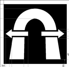
and the driver decides to stop at the indicated safe area, he/she shall stop the train taking into account its length.
When the following marker board is encountered:

the driver is informed that he/she has reached the end of the safe area.
6.36.PROPELLING IN RV
A train has to be moved in the reverse direction inside an emergency propelling area.
6.36.1.Preparing the movement to be performed in RV
When the train is at a standstill and the following symbol is displayed:

the driver shall trigger the transition to RV while informing the signaller if possible and taking into account any further instructions.
6.36.2.Running in RV
When the following symbol is displayed with a flashing frame:

the driver shall:
(I)acknowledge,
(II)propel the train following any instructions given by the signaller as soon as the following symbol is displayed:

(III)not exceed the maximum speed for RV,
(IV)not exceed the permitted distance to run.
6.36.3.Exceeding the permitted distance in RV
When the following text message is displayed with a flashing frame:
‘RV distance exceeded’,
the driver shall:
(I)report to the signaller,
(II)acknowledge at a standstill if the permitted distance in RV has not been extended,
(III)release the brake.
6.36.4.Exit from RV
After the train has completed its propelling and as soon as it is at a standstill the driver shall report to the signaller. If no additional movement in RV is required the driver shall close the driving desk to exit RV.
6.37.REACTING TO UNINTENTIONAL MOVEMENTS
After being at a standstill the train / shunting composition has moved unintentionally and the ETCS on-board has triggered the brake.
Levels 1, R
When the following text message is displayed:
‘Runaway movement’,
the driver shall secure the train / shunting composition according to internal RU rules and acknowledge the brake application.
6.38.MANAGING ROUTE UNSUITABILITY DETECTED BY THE ON-BOARD SYSTEM
When any of the following messages is displayed:
‘Route unsuitable - loading gauge’
‘Route unsuitable - traction system’
‘Route unsuitable – axle load category’
a route unsuitability is detected.
The driver shall stop the train using service brake.
The driver shall inform the signaller and follow any instructions given.
6.39.AUTHORISING THE PASSING OF AN EOA
It is necessary to authorise a driver to pass an EOA.
Levels 1, R
Before authorising a driver to pass an EOA by means of European Instruction 1 the signaller shall, according to non-harmonised rules:
(I)check if all the conditions for the route are met,
(II)check all restrictions and / or instructions that are necessary and include them in European Instruction 1,
(III)check for temporary speed restrictions to be included in European Instruction 1.
If the signaller can establish that the track up to the end of the authorisation to be issued is free then he/she may exempt the driver from running on sight in SR .
It is possible to provide more than one European Instructions for an equal number of consecutive ETCS Stop Markers to be passed.
To pass the EOA, the driver shall:
(IV)receive European Instruction 1 from the signaller for this EOA,
(V)check the applicable speed limit,
(VI)use the override function, and
(VII)when the following symbol is displayed:
–start the train or continue moving,
–not exceed the override EOA speed while this symbol is displayed.
6.40.REACTING TO UNEXPECTED SITUATIONS WHEN PREPARING A TRAIN MOVEMENT
6.40.1.The traction unit has to move as a train but an acknowledgement for SH is requested
When the following symbol is displayed with a flashing frame:
the driver shall inform the signaller about the situation, then acknowledge and proceed according to the instructions received from the signaller.
6.40.2.The train is rejected
When the following text message is displayed on the DMI:
‘Train is rejected’
the driver shall inform the signaller about the situation. The driver and signaller shall apply non-harmonised rules.
6.41.RESPONDING TO A TRIP
A train or a shunting movement is tripped.
Levels 1, R
6.41.1.Immediate measures
When the following symbol is displayed:

the driver shall assume that there is a potentially dangerous situation and he/she shall perform all actions necessary to avoid or reduce the effect of this situation. This may include moving the train / shunting composition backwards.
When the following symbol is displayed with a flashing frame:

the driver shall acknowledge and apply the brakes.
a)
In case an immediate backward movement is necessary due to an emergency
When the driver decides or is instructed by the signaller to move the train / shunting composition backwards due to an emergency
and
when the following symbol is displayed:

the driver shall move the train / shunting composition backwards following any instructions given by the signaller.
After moving backwards as soon as the train / shunting composition is at a standstill, the driver shall inform the signaller about the situation.
b)
In all other cases
When the following symbol is displayed:
the driver shall inform the signaller about the situation and follow any instructions given.
6.41.2.To restart
a)
In the initial direction
Before giving authorisation to the driver to proceed after a trip by means of European Instruction 2 the signaller shall, according to non-harmonised rules:
(I)check if all the conditions for the route are met,
(II)check all restrictions and / or instructions that are necessary and include them in European Instruction 2,
(III)check for temporary speed restrictions to be included in European Instruction 2.
If the signaller can establish that the track up to the end of the authorised movement is free then he/she may exempt the driver from running on sight in SR .
To proceed the driver shall:
(I)receive European Instruction 2 with all additional instructions given by the signaller,
(II)according to the task to be performed select ‘Start’ or ‘SH’ and follow the instructions given in European Instruction 2,
(III)restart the train / shunting movement.
If in ETCS level R, at any step of the procedure, the following text message is displayed:
‘Communication error’,
the driver shall inform the signaller about the situation. The signaller and driver shall apply rule ‘Authorising the passing of an EOA’ (section 6.39). In this case, European Instruction 1 shall be issued by the signaller instead of European Instruction 2.
b)
In the opposite direction
The signaller shall order the driver to remain at standstill and to perform End of Mission by means of European Instruction 3, and then to restart in the opposite direction by means of European Instruction 7.
The driver shall carry out the End of Mission and then apply rule ‘Putting the on-board into service’ (section 6.1) and rule ‘Preparing a movement’ (section 6.2). If the driver is not operating from the leading cab, he/she shall apply internal RU rules to ensure safe running.
6.41.3.No movement required after a trip
In the case of a train / shunting compositionnot required to be moved after a trip, the signaller shall order the driver to remain at standstill and to perform End of Mission by means of European Instruction 3.
6.41.4.Trip in SH when passing a defined border of a shunting area
When a shunting movement is tripped when passing a defined border of a shunting area the driver and signaller shall apply non-harmonised rules.
6.42.MANAGING AN ETCS TRACKSIDE MALFUNCTION
The on-board receives the information of an ETCS trackside equipment malfunction.
Levels 1, R
When the following text message is displayed:
‘Trackside malfunction’,
the driver shall inform the signaller about the situation.
6.43.MANAGING INCOMPATIBILITY BETWEEN ETCS TRACKSIDE AND ETCS ON-BOARD
An incompatibility between ETCS trackside and ETCS on-board is detected by the system and the train is tripped.
Levels 1, R
When the following text message is displayed:
‘Trackside not compatible’,
the train cannot continue in ETCS.
The driver shall apply rule ‘Responding to a trip’ (section 6.41).
6.44.MANAGING A LEVEL CROSSING NOT PROTECTED
The train is approaching a level crossing which is not protected.
Levels 1, R
6.44.1.If in FS, OS or LS
When the following symbol is displayed:

the driver shall apply rule 7 of Section B2 of Appendix B.
6.44.2.If in SR
When the following text message is displayed:
‘Level crossing not protected’,
the driver shall apply rule 7 of Section B2 of Appendix B.
6.45.MANAGING A BALISE READ ERROR
A balise read error occurs and the brakes are triggered by the ETCS on-board (the train is not tripped).
Levels 1, R
When the following text message is displayed:
‘Balise read error’,
and the train is not tripped, the driver shall inform the signaller about the situation.
If no new MA is received when the train has come to a standstill, the signaller shall authorise the driver to pass the EOA by applying rule ‘Authorising the passing of an EOA’ (section 6.39 ).
If the situation is repeated, the driver and signaller shall apply non-harmonised rules.
6.46.MANAGING A FAILED LEVEL TRANSITION
The transition takes place but no MA valid beyond the transition point is received on-board or the transition does not take place when passing the transition point.
Levels 1, R
The ETCS level transition point may be marked through the following trackside marker board:
 *
*
* For the exact dimensions and layout of the icon, EN 16494/2015 needs to be used
6.46.1.If the train has been tripped
The driver and signaller shall apply rule ‘Responding to a trip’ (section 6.41 ).
After selecting ‘Start’ the driver shall:
(I)check the correct ETCS level to be selected,
(II)change the ETCS level (rule ‘Manual change of data’ (section 6.1.2)),
and then restart the train.
In case the ETCS level to be selected is not available on-board, the driver and signaller shall apply rule 15 of Section B2 of Appendix B.
6.46.2.If in SR
The driver shall:
(I)stop the train,
(II)apply the following rule ‘In all other cases’ (section 6.46.3).
6.46.3.In all other cases
The driver shall:
(I)inform the signaller about the situation,
(II)when at a standstill, check the correct ETCS level to be selected,
(III)change the ETCS level (rule ‘Manual change of data’ (section 6.1.2)),
and then restart the train.
In case the ETCS level to be selected is not available on-board, the driver and signaller shall apply rule 15 of Section B2 of Appendix B.
6.47.MANAGING ABSENCE OF RBC INFORMATION
There is no RBC information received in an area not identified as a radio hole and the brakes are triggered by the ETCS on-board (the train is not tripped).
When the following text message is displayed:
‘Communication error’,
the driver shall inform the signaller about the situation when at a standstill.
If no new MA is received when the train has come to a standstill, the signaller shall authorise the driver to pass the EOA by applying rule ‘Authorising the passing of an EOA’ (section 6.39 ).
6.48.MANAGING A RADIO COMMUNICATION FAILURE
An ETCS radio communication failure occurs.
Levels 0, 1, R, NTC
When the following symbol is displayed:

the driver shall check the ETCS level, the radio network identification, the RBC identification / phone number, and correct them if necessary (rule ‘Manual change of data’ (section 6.1.2)).
If the radio communication with the RBC still cannot be established, the driver shall inform the signaller about the situation.
a) when in ETCS level R preparing a movement and the traction unit has to move in SH
The driver and the signaller shall apply non-harmonised rules.
b) when in ETCS level R preparing a tandem movement
The driver of the non-leading traction unit shall inform the driver of the leading traction unit about the radio communication failure. Both drivers shall apply internal RU rules.
c) in all other cases
The signaller shall authorise the driver to pass the EOA by applying rule ‘Authorising the passing of an EOA’ (section 6.39).
6.49.MANAGING A FAILURE OF SELF TEST
When the information about the failure of an ETCS device is shown to the driver, he/she shall switch off the ETCS on-board and then switch it on again to trigger a new self test. If the same information is shown again, the driver shall attempt to troubleshoot the problem using the applicable technical information. If this attempt fails or is not possible, the driver shall inform the signaller about the situation.
The driver shall request a change of traction unit.
If the traction unit must be moved the driver and signaller shall apply rule 15 of Section B2 of Appendix B.
6.50.MANAGING A FAILURE AFFECTING THE ON-BOARD RADIO EQUIPMENT
When a failure of the on-board radio equipment is detected the driver shall inform the signaller about the situation.
6.50.1.During the preparation of the traction unit
The driver shall request a change of traction unit.
If the traction unit must be moved, the driver shall inform the signaller, apply RU rules and any instructions given by the signaller.
If the traction unit need not be moved, the driver shall switch off the ETCS on-board.
6.50.2.While running
Levels 1 with infill function by radio, R
The driver and signaller shall apply rule 15 of Section B2 of Appendix B.
6.51.MANAGING A FAILED DMI
The DMI fails.
Levels 0, 1, R, NTC
When the DMI fails the driver and signaller shall apply rule 15 of Section B2 of Appendix B, unless another DMI is available on the desk.
6.52.]MANAGING A SYSTEM FAILURE
When the following symbol is displayed:

the driver shall attempt to troubleshoot the problem using the applicable technical information.
If this attempt fails or is not possible, the driver and signaller shall apply rule 15 of Section B2 of Appendix B.
6.53.MANAGING A NTC FAILURE
When the following text message is displayed:
‘[name of NTC] failed’
the driver shall acknowledge and apply non-harmonised rules.
6.54.MANAGING A VBC
The driver and signaller shall apply non-harmonised rules.
6.55.RUNNING IN AD
The driver switches the ATO on-board on.
Levels 1, R
6.55.1.Engaging ATO
When the following symbol is displayed, the driver may engage automated train operation by selecting it:

When ATO is engaged the following symbol is displayed:

6.55.2.Running in ATO
When the following symbol is displayed:

the driver:
(I)shall activate ‘skip stopping point’ when required by the timetable or if instructed to do so
(II)after coming to a standstill at an operational stopping point, may manually move the train to correct its position, in the forward direction (when
 is displayed) after notifying any passengers or in the reverse direction (when
 is displayed, if authorised by the signaller and after notifying any passengers accordingly, until
 is displayed.
(III)shall operate door opening/closing if invited to do so by the respective DMI indications
6.55.3.Disengaging ATO
The following driver actions will cause ATO to disengage:
(I)selecting the button associated with this icon
(II)applying the brake
(III)switching off the ATO
(IV)selecting Override
Once the ATO disengages, the driver shall observe the icon displaying the current ETCS mode and shall follow the rule applicable for the mode entered.
6.56.MANAGING A TIMS FAILURE
Level R when train integrity has to be confirmed
When the train preparer / driver of a train scheduled to run or running in an ETCS level R area where train integrity has to be confirmed becomes aware that the TIMS has failed, he/she shall apply rule 15 of Section B2 of Appendix B.
6.57.MANAGING AN IMPAIRED ODOMETER
When the following text message is displayed:
‘odometer impaired’
the driver shall apply rule 15 of Section B2 of Appendix B.
7.GSM/R VOICE RADIO OPERATIONAL RULES
7.1.SELECTING THE GSM-R MODE
The driver needs to change the GSM-R mode.
When the displayed GSM-R mode does not correspond with the task to be performed (train or shunting movement), the driver shall select the correct mode.
7.2.ENTERING THE FUNCTIONAL NUMBER
The train preparer / driver is performing the registration.
The train preparer / driver shall enter the functional number:
(I)as early as possible before the initial departure,
(II)every time the functional number changes.
7.3.SELECTING THE GSM-R NETWORK AT A BORDER CROSSING
The train is approaching a border crossing.
7.3.1.Inhibition of automatic network selection
When approaching a section in the vicinity of network borders, the driver shall inhibit the (on-board) automatic network selection function in the cab radio, if activated, when instructed to do so by the Route Book.
7.3.2.Selection of another GSM-R network
When according to the Route Book or a GSM-R network marker
 *
*
* For the exact dimensions and layout of the icon, EN 16494/2015 needs to be used
the driver is instructed to select another GSM-R network, he/she shall select the indicated GSM-R network on the cab radio unless the network is selected following an ETCS trackside command. If the driver is engaged in an emergency call, he/she shall not proceed with the manual selection as long as the call is active.
7.4.PERFORMING A DE-REGISTRATION
The train has to be manually de-registered.
At the end of the train run or when requested by the signaller, the driver shall carry out the de-registration .
7.5.INTENTIONALLY BLANK
7.6.MANAGING A FAILURE OF SELF TEST
When the following text message is displayed:
‘Self-test failed’,
the driver shall inform the signaller about the situation.
The driver and signaller shall apply rule 8 of Section B2 of Appendix B.
7.7.MANAGING A LACK OF GSM-R NETWORK AFTER THE TRAIN HAS ENTERED SERVICE
When the following text message is displayed:
‘No network’,
The driver and signaller shall apply rule 8.2 of Section B2 of Appendix B.
7.8.INTENTIONALLY BLANK
7.9.MANAGING A FAILURE OF DE-REGISTRATION
If the de-registration is not possible the driver shall inform the signaller about the situation, apply RU rules and follow any instructions given.
7.10.TAKING MEASURES IN CASE THE FUNCTIONAL NUMBER IS NOT AVAILABLE
When the following text message is displayed:
‘Number not available’,
the train preparer / driver shall check the number and try again to register using the correct number.
If the registration fails again, he/she shall inform the signaller about the situation, apply RU rules and follow any instructions given.
7.11.TAKING MEASURES IN CASE THE FUNCTIONAL NUMBER IS ALREADY USED
When the following text message is displayed:
‘Number already used’,
the train preparer / driver shall check the number and try again to register using the correct number.
If the functional number used was correct, the train preparer / driver shall call that functional number and ask the other party to de-register the current number unless prevented from doing so by non-harmonised rules.
(I)If the call is successful and the other party de-registers the number in question, the train preparer / driver shall re-start the functional number registration procedure.
(II)If there is no response to the call, the train preparer / driver shall initiate forced de-registration of the specific functional number.
In all other cases, the train preparer / driver shall inform the signaller on the issue and follow any instructions given.
7.12.MANAGING A FAILURE WHEN REGISTERING THE FUNCTIONAL NUMBER
When it is not possible to register the functional number, the train preparer / driver shall inform the signaller about the situation, apply RU rules and follow any instructions given.
7.13.GSM-Public as primary communication (if this option is available on-board)
7.13.1.Changing-over from GSM-R to GSM-Public
When instructed through a marker board indicating entry in a GSM network or through instructions on the route book, the driver shall select the indicated public GSM network, unless the network is automatically selected.
The driver and signaller shall apply non-harmonised rules.
7.13.2.Changing-over from GSM-Public to GSM-R
When instructed through a marker board indicating (re-)entry into a GSM-R network or through instructions on the route book, the driver shall select the indicated GSM-R network, unless the GSM-R network is automatically selected.
If the GSM-R network is not available, the driver shall apply rule 8.2 of Section B2 of Appendix B.
7.14.GSM-Public as fall-back communication (if this option is available on-board)
7.14.1.Changing-over from GSM-R to GSM-Public
When the connection to the GSM-R network is lost, the driver shall select an alternate GSM public network if authorised to do so according to instructions previously given by the signaller or provided in the rule and/or route book, unless the on-board GSM-R terminal is configured to carry out an automatic network selection.
The driver and signaller shall apply non-harmonised rules.
7.14.2.Changing-over from GSM-Public to GSM-R
When instructed by the signaller or through instructions in the rule and/or route book, the driver shall manually select the indicated GSM-R network on the cab radio, unless the on-board GSM-R terminal is configured to carry out an automatic network selection.
8.PART A - INTENTIONALLY BLANK
9.PART B – LIST OF ETCS OPERATIONAL TRAIN CATEGORIES
The ETCS operational train categories are listed in the table below:
|
label
|
type of train
|
type of brake
|
cant deficiency
|
|
PASS 1
|
passenger train
|
P
|
80
|
|
PASS 2
|
|
|
130
|
|
PASS 3
|
|
|
150
|
|
TILT 1
|
tilting passenger train
|
|
165
|
|
TILT 2
|
|
|
180
|
|
TILT 3
|
|
|
210
|
|
TILT 4
|
|
|
225
|
|
TILT 5
|
|
|
245
|
|
TILT 6
|
|
|
275
|
|
TILT 7
|
|
|
300
|
|
FP 1
|
freight train
|
|
80
|
|
FP 2
|
|
|
100
|
|
FP 3
|
|
|
130
|
|
FP 4
|
|
|
150
|
|
FG 1
|
|
G
|
80
|
|
FG 2
|
|
|
100
|
|
FG 3
|
|
|
130
|
|
FG 4
|
|
|
150
|
10.PART C – TABLE OF REFERENCES TO NON-HARMONISED RULES
The non-harmonised rules defined in this Appendix are listed in the table below.
The table further defines the entity (IM or RU) that is in charge of laying down any necessary further details for each of those rules in their respective safety management system.
|
Reference
|
Subject
|
In charge
|
|
5.1.1
|
Driver’s observance of the line in cab-signalling
|
RU
|
|
6.2.4
6.39
6.41.2
|
Checking route conditions
|
IM
|
|
6.2.4
6.39
6.41.2
|
Checking necessary restrictions and / or instructions for running in SR
|
IM
|
|
6.2.4
6.39
6.41.2
|
Checking speed restrictions lower than the maximum speed for SR
|
IM
|
|
6.3.1
|
Manual entry into SH
|
RU
|
|
6.3.3
|
Running in SH
|
IM
|
|
6.3.6
|
SH refused by the RBC / SH request failed
|
IM
|
|
6.3.7
|
Passing a defined border of a shunting area
|
IM
|
|
6.7.1
|
Announcement of an ETCS level 0 transition
|
IM
|
|
6.7.3
|
Running in ETCS level 0
|
IM
|
|
6.11.1
|
Announcement of an ETCS level NTC transition
|
IM
|
|
6.11.3
|
Running in ETCS level NTC
|
IM
|
|
6.15
|
Acknowledgement of LS
|
IM
|
|
6.15
|
Running in LS
|
IM
|
|
6.16
|
Acknowledgement of UN
|
IM
|
|
6.16
|
Running in UN
|
IM
|
|
6.17
|
Acknowledgement of SN
|
IM
|
|
6.17
|
Running in SN
|
IM
|
|
6.28
|
Sounding the audible warning device
|
IM
|
|
6.33.1
|
Revoking an authorisation for ERTMS train movement
|
IM
|
|
6.34.3
|
Protecting and restarting shunting movements
|
IM
|
|
6.40.2
|
The train is rejected when preparing a movement
|
IM
|
|
6.41.4
|
Trip in SH
|
IM
|
|
6.45
|
Managing a balise read error
|
IM
|
|
6.48 a)
|
Managing a radio communication failure when SH is requested
|
IM
|
|
6.53
|
Managing a NTC failure
|
IM
|
|
6.54
|
Managing a VBC
|
IM
|
|
7.11
|
Taking measures in case the functional number is already used
|
IM
|
|
7.13.1
|
Changing-over from GSM-R to GSM-Public
|
IM
|
|
7.14.1
|
Changing-over from GSM-R to GSM-Public
|
IM
|
‘;
(39)Appendix B is amended as follows:
(a)the title is replaced by the following:
‘ Appendix B
Fundamental operational principles and common operational rules’;
(b)point 10(1) is replaced by the following:
ʻ(1)
If a train is stopped by failure, the driver shall immediately inform the signaller about the failure and the circumstances of the failure. If a train stops unexpectedly and no communication is possible with the driver, the signaller shall activate its own procedure in order to guarantee the safety of operations.ʼ;
(c)in point 13, the following fourth paragraph is added:
‘Anyone who receives an emergency call shall listen, not intervene in the communication that is in progress except to provide elements relevant to the context.’;
(d)point 14 is replaced by the following:
‘14.
IMMEDIATE ACTIONS TO PREVENT DANGER TO TRAINS
Any railway undertaking/infrastructure manager staff who becomes aware of a danger to trains shall take immediate action to stop any trains which may be affected, alert the signaller and take any other action as necessary to avoid harm or loss, and in particular:
(1)Any driver made aware of a danger to their train shall stop as soon as it is safe to do so and alert the signaller immediately to the danger using the emergency call.
(2)Any signaller made aware of a danger shall alert all drivers as appropriate through an emergency call or using any other available means.’;
(e)point 15 is amended as follows:
(a)the third paragraph is replaced by the following:
‘If the driver becomes aware of a failure of any on-board equipment that affects the running of the train, the driver shall:
–Inform the signaller of the situation, the stopping point and the restrictions on the train should the train be allowed to continue its mission,
–Not commence or recommence the mission until permission to do so has been granted by the signaller.’;
(b)the following fourth paragraph is inserted:
‘If the signaller gives permission for the train to start or continue its mission then the driver shall proceed in accordance with the restrictions placed upon the train,’;
(f)the following point 18 is added:
‘18.ENTERING AN OCCUPIED TRACK WITHIN A STATION
–In case of an unplanned entry into an occupied track, the signaller shall, before authorising the entry to the occupied track, ensure that the involved drivers are informed of the circumstances.
–In all cases when a train has to enter an occupied track, the signaller shall obtain confirmation that the occupying train or will not move towards the train entering the occupied track.’;
(40)Appendix C is amended as follows:
(a)in Section C1, point 3 is replaced by the following:
‘3. Communication rules
In order that safety-related communication is correctly understood, whatever the means of communication used, the following rules shall be used:’;
(b)Section C2 is amended as follows:
(i) point 1 is replaced by the following
‘1. Introduction
Railway undertakings and infrastructure managers shall use European Instructions in the communication procedure in the following cases:
(1)Permission to pass an End of Authority or stop signal;
(2)Permission to proceed after trip;
(3)Obligation to remain at standstill;
(4)Revocation of an instruction;
(5)Obligation to run with speed restriction;
(6)Obligation to run on sight;
(7)Permission to start after preparing a movement;
(8)Permission to pass defective level crossing(s);
(9)Obligation to run with power supply restriction;
(10-20) RESERVED
The numbers 1 to 20 are reserved for European instructions.
The use of the European instructions numbers 1-4 and 7 is mandatory for ETCS, in accordance with the rules of Appendix A.
If an operational instruction related to a class B system requires more information than the European instructions, a national instruction may be used instead. In such a case, the infrastructure manager may set out these requirements in its national instructions.
If numbered, the national instructions drawn up by the individual infrastructure managers shall start from 21 onwards.
The national instructions shall contain at least the same content as that for a European instruction.
Whenever the signaller needs to issue an operational instruction for which a European instruction exists, the signaller shall use this European instruction.’;
(ii)in point 2, the following fourth paragraph is added:
‘By way of derogation, a European Instruction 3 can also be revoked by a European Instruction 1, 2 or 7 without requiring a dedicated European Instruction 4.’;
(iii)in point 3, the first paragraph is replaced by the following:
‘An operational instruction includes information delivered electronically, verbally, physically on paper or as verbal instructions to be written down by the train driver or by other safe methods of communication with the same level of information.’;
(iv) points 6, 7 and 8 are replaced by the following:
‘6.
European instructions
Each tick box, field of information and option for input in a field contained in a European instruction shall be given its own alphabetical or numerical identifier. Numbered identifiers that are part of more than one European instruction shall be given an identifier starting with ‘x’ instead of the number of the European instruction. This ‘x’ may only be replaced by the number of the European instruction when transmitting this instruction digitally.
While the content and the identifiers must be used and the alphabetical and numerical order of the identifiers must be respected, the format itself shall be indicative.
If a specific tick box, field or option for input in a field is not to be used in a Member State or on the network of an infrastructure manager, there is no obligation to display this tick box, field or option for input in a field in the European instruction.
No tick box, field or option for input in a field shall be added.
The scope of each individual field cannot extend beyond the scope of application of the European instruction to which it belongs.
The infrastructure manager and the railway undertaking may add guidance on how to fill in and read the forms of the European instructions, under the condition that this guidance is not part of the communication procedure.


7.
Communication of an operational instruction
The following terminology shall be used in the communication procedure by all the parties:
|
Situation
|
Terminology
|
|
Starting the delivery of an operational instruction
|
‘Prepare procedure … [identification of the procedure]’
|
|
Confirming that an operational instruction may be delivered
|
‘Ready for procedure … [identification of the procedure]’
|
|
Cancelling an operational instruction
|
‘Cancel procedure… [identification of the procedure]’
|
|
If the message is subsequently to be resumed, the procedure shall be repeated from the start
|
‘Error during transmission’
|
|
When a transmission error is discovered by the sender, the sender shall request cancellation
|
‘Error (+ prepare new procedure … [identification of the procedure])’
Or
‘Error (+ I say again)’
|
|
Error during read back
|
‘Error (+ I say again)’
|
|
Misunderstanding: if one of the parties does not fully understand a message, the message shall be repeated
|
‘Say again (+speak slowly)’
|
8.
Book of Operational Instructions
The infrastructure manager is responsible for drawing up the Book of Operational Instructions in its operating languages.
All the forms of the national instructions and the European instructions to be used shall be assembled in a document or a computer medium called the Book of Operational Instructions.
This Book of Operational Instructions shall be used by both the driver and the staff authorising the movement of trains. The book used by the driver and the book used by the staff authorising the movement of trains shall be structured and numbered in the same way.
The Book of Operational Instructions shall comprise two parts.
The first part contains at least the following items:
–an index of the European instructions as used by the infrastructure managers;
–an index of the national operational instructions;
–a list of situations to which each operational instruction applies;
–the way of delivering each operational instruction, including whether it is allowed to be written down by the driver while running;
–the table containing the international phonetic alphabet.
The second part contains, in the operating languages of the infrastructure manager, the forms of:
–
the European instructions
–
the national operational instructions.
These shall be collected by the railway undertaking and given to the driver. Railway undertakings operating in more than one IM network provide the driver with the generic forms of the European instructions, even when some fields are not used by some infrastructure managers on the networks of which the railway undertaking will operate.’;
(41)Appendix D is amended as follows:
(a)in Section D1, the table is amended as follows:
(i)
the first line ‘Traffic loads and load carrying capacity of infrastructure’ is replaced by the following: ‘
|
Traffic loads and load carrying capacity of infrastructure
|
Static axle loads and design and operational masses in the following load cases:
-design mass as defined in Regulation (EU) 1302/2014
o in working order;
ounder normal payload;
ounder exceptional payload;
-Where relevant operational mass in accordance with EN 15663: 2017- A1 2018:
oin working order;
ounder normal payload.
Maximum design speed;
Vehicle length;
The position of the axles along the unit (axle spacing).
EN line category;
For vehicles capable of carrying a payload of passengers: EN line category for the standard value of payload in standing areas and – in case of application – for any particular value of payload in standing areas, according to Point 6.4 of EN 15528:2021.
Static compatibility check for wagons:
Permissible payload for different line categories according to WAG TSI.
|
1.1.1.1.2.4 Load capability
1.1.1.1.2.4.1 National classification for load capability
1.1.1.1.2.4.2 Compliance of structures with the High Speed Load Model (HSLM)
1.1.1.1.2.4.3 Railway location of structures requiring specific checks
1.1.1.1.2.4.4 Document(s) with the procedure(s) for static and dynamic route compatibility checks
|
x
|
x
|
The static compatibility checks for vehicles shall be performed according to Point 7 of EN 15528:2021 and additional procedure(s) or relevant information if provided by the infrastructure manager through RINF under parameter 1.1.1.1.2.4.4.
For the United Kingdom in relation to Northern Ireland networks, the static compatibility checks for vehicles shall be performed according to relevant national rules in accordance with 4.2.7.4 (4) of Commission Regulation (EU) No 1299/2014.
Any requirement set out by the infrastructure manager which relates to the passenger payload, to be considered during route compatibility checks for vehicles capable of carrying a payload of passengers, shall be included in the procedure(s) or relevant information provided by the infrastructure manager through RINF under parameter 1.1.1.1.2.4.4. Such procedure may take into account technical or operational measures which have an impact on the passenger payload on standing areas.
The dynamic compatibility checks for trains, when necessary in accordance with the information provided by the infrastructure manager, shall be performed according to the procedure(s) or relevant information provided by the infrastructure manager through RINF under parameter 1.1.1.1.2.4.4.
|
’;
(ii)
the following new line is inserted after the line ‘Gauging’: ‘
|
Specific check for Combined Transport
|
Wagon Compatibility Code, Wagon Correction Digit and ILU Technical Number
(WCC + ILU Technical Number) combined with the freight Wagon Correction Digit = CT code
|
1.1.1.1.3.4
Standard combined transport profile number for swap bodies
1.1.1.1.3.4.1
Standard combined transport profile number for roller units
1.1.1.1.3.4.2
Standard combined transport profile number for container
1.1.1.1.3.5
Standard combined transport profile number for semi-trailers
(CT Line code)
|
|
X
|
Comparison between the CT code and the CT Line code (Compatibility demonstrated when CT code ≤ CT Line code)
|
’;
(iii)
the line ‘Train detection system’ is replaced by the following: ‘
|
Train detection systems
|
Information if the vehicle has electrical or electronic equipment on board creating interference current in the rail or if the vehicle has electrical or electronic equipment on board creating interference electromagnetic fields close to the wheel sensor
Type of train detection systems for which the vehicle has been designed and assessed by tests performed in accordance with ERA/ERTMS/033281
|
1.1.1.3.7.1.1 Type of train detection system
1.1.1.3.7.1.2 Type of track circuits or axle counters to which specific checks are needed.
1.1.1.3.7.1.3 Document with the procedure(s) related to the type of train detection systems declared in 1.1.1.3.7.1.2
|
X
|
|
Comparison only needed if:
·If 1.1.1.3.7.1.1 is “track circuit” then only for vehicles having electrical or electronic equipment on board creating interference current in the rail
·If 1.1.1.3.7.1.1 is “wheel detector” then only for vehicles having electrical or electronic equipment on board creating interference electromagnetic fields close to the wheel sensor
·If 1.1.1.3.7.1.1 is “loop” then not needed.
Comparison of the declared type of train detection system(s) between vehicle and the intended route.
Note.
At vehicle authorisation, based on TSIs and the documents specifying specific cases, referenced in RINF based on ERA/ERTMS/033281, the technical compatibility is verified between the vehicle and all train detection system(s) of the network(s) in the area of use.
In duly justified cases (e.g. problems of non-detection of the vehicle occurring during operation), tests and/or checks could be done after vehicle authorisation, involving the railway undertaking and infrastructure manager.
|
’;
(iv)
the line ‘Voltages and frequencies’ is replaced by the following: ‘
|
Voltages and frequencies
|
Energy supply system :
-Nominal voltage and frequency;
-Type of contact line system
-For existing not TSI compliant vehicle and intended to operate in the specific lines mentioned in TSI ENE 1301/2014 section 7.4.2.2.1: Umax2.
|
1.1.1.2.2.1.1 Type of contact line system
1.1.1.2.2.1.2 Energy supply system (Voltage and frequency)
Specific cases defined in TSI ENE 1301/2014 section 7.4.2.2.1:
1.1.1.2.2.1.3 Umax2 for lines referred to in sections 7.4.2.2.1 and 7.4.2.11.1 of Regulation (EU) 1301/2014*.
|
X
|
|
Comparison of the declared voltage between vehicle and the intended route of the traction supply system (nominal voltage and frequency) and type of contact line system.
|
’;
(v)
the line ‘ETCS – Train Integrity’ is replaced by the following:‘
|
ETCS
|
Managing information about the completeness of the train (not from driver)
|
1.1.1.3.2.8 Train integrity confirmation from on-board (not from driver) necessary for line access
|
X
|
X
|
Comparison that vehicle/train is able to confirm (not from driver) the train integrity if required by trackside.
|
’;
(vi)
the following two new lines are inserted after the line ‘ETCS- Train Integrity’:
‘
|
ETCS
|
Envelope of legally operated ETCS system versions
|
1.1.1.3.2.10 ETCS M_version
|
X
|
|
Comparison that the ETCS M_VERSION value in RINF is in the range of the legally operated ETCS system vesions supported by the vehicle.
|
|
ETCS
|
Safe consist length information from on-board necessary for access to the line and SIL level
|
1.1.1.3.2.11 Safe consist length information from on-board necessary for access to the line and SIL level
|
X
|
X
|
Comparison that vehicle/train is able to provide the safe consist length information with the minimum required level indicated in RINF.
|
’;
(vii)
the line ‘GSM-R -SIM Card GSM-R Home Network’ is replaced by the following:
‘
|
GSM-R
|
Voice SIM Card GSM-R Home Network
|
1.1.1.3.3.5 GSM-R networks covered by a roaming agreement
|
X
|
|
Comparison that the SIM Card GSM-R Home Network is in the list of GSM-R networks with roaming agreement for all Points in the route. This has to be performed for all SIM Cards in the vehicle.
|
’;
(viii)
the following new line is inserted after the line ‘GSM-R -SIM Card GSM-R Home Network’:‘
|
GSM-R
|
Data SIM Card GSM-R Home Network
|
1.1.1.3.3.5 GSM-R networks covered by a roaming agreement
|
X
|
|
Comparison that the SIM Card GSM-R Home Network is in the list of GSM-R networks with roaming agreement for all Points in the route. This has to be performed for all SIM cards in the vehicle.
|
’;
(ix)
the line ‘GSM-R - SIM card support of group ID 555’ is replaced by the following:
‘
|
GSM-R
|
GSM-R SIM card support of group ID 555
|
1.1.1.3.3.4 Use of Group 555
|
X
|
|
Check that the Group ID 555 is used trackside. If this is not configured on-board, alternative operational procedures should be prior established with the infrastructure manager.
|
’;
(b)Section D2 is amended as follows:
(i) line 3.4.3 is replaced by the following:
‘
|
‘3.4.3
|
Special technical conditions required to switch over between ERTMS/ETCS and Class B systems, boundary locations between ERTMS/ETCS and Class B systems.
|
’;
(ii) line 3.4.4 is replaced by the following:
‘
|
3.4.4
|
Radio network ID(s) used in the route and special instructions (location) to switch over between different radio systems’;
|
’;
(iii)new lines 3.4.7, 3.4.8 and 3.4.9 are inserted: ‘
|
3.4.7
|
ID(s) or phone number(s) and areas of authority (boundary locations) of ERTMS/ETCS Radio Block Centers covering the route
|
|
3.4.8
|
ATO baseline and system version installed lineside
|
|
3.4.9
|
ATO communication system supported from trackside
|
’;
(c)the following Section D3 is added:
‘D3
ERTMS trackside engineering information relevant to operation that the infrastructure manager shall provide to the railway undertaking
Notes:
1.The information provided herein is complementary to the route compatibility check, which is assumed to have already been performed for a train intended to operate on a route. It has to be provided by the infrastructure managers through RINF.
2.Most of the information listed below is not otherwise visible to the driver or can only be indirectly perceived under certain operational conditions, usually by observing the system behaviour in certain situations.
3.Item 1.5 lists the minimum set of ETCS National Values required to be made available to the railway undertakings. Infrastructure managers shall also provide upon request to a railway undertaking the complete set of National Values.
4.The ERTMS terms mentioned in the table are defined in the glossary and system requirements specification of the Control-command and Signalling TSI (under indexes 3 and 4 respectively of Appendix A ).
5.The information provided in this Appendix will enhance drivers’ knowledge of the operational conditions they need to consider when running under ERTMS in the infrastructure manager’s network. It can be used in drivers’ training and may be integrated under internal railway undertaking rules and procedures.
|
Number
|
Information
|
Justification/notes
|
|
1
|
ETCS specificities
|
|
|
1.1
|
Whether the ETCS trackside is engineered to transmit Track Conditions and if yes, which ones
|
If the trackside does not provide Track Conditions, the driver will need to be informed about such conditions via alternative methods
|
|
1.2
|
Whether the ETCS trackside implements the Level Crossing (LX) procedure or an equivalent solution
|
If the trackside does not implement any solution to cover defective LXs (which are normally protected by means of a technical system), then drivers will be required to comply with instructions received from other sources
|
|
1.3
|
The cant deficiency used to determine the basic Static Speed Profile of the line and other cant deficiency train categories for which the ETCS trackside is configured to provide Static Speed Profiles
|
Essential information for drivers of trains with a worse (lower) tolerated cant deficiency than those for which the ETCS trackside provides Static Speed Profiles
|
|
1.4
|
Reasons for which an ETCS Radio Block Center can reject a train
|
List of cases subject to system design choices made by the infrastructure manager
|
|
1.5
|
ETCS National Values
|
Minimum set of parameters to be communicated to the railway undertakings
|
|
1.5.1
|
D_NVROLL
|
Parameter used by the ETCS on-board to supervise the distance allowed to be travelled under the roll-away protection and the reverse movement protection
|
|
1.5.2
|
Q_NVEMRRLS
|
Qualifier defining whether the application of the emergency brake for reasons other than a trip can be revoked as soon as the conditions for it have disappeared or after the train has come to a complete standstill
|
|
1.5.3
|
V_NALLOWOVTRP
|
Maximum speed allowed when selecting ‘Override EOA’
|
|
1.5.4
|
V_NVSUPOVTRP
|
Permitted speed limit supervised when ‘Override EOA’ is active
|
|
1.5.5
|
D_NVOVTRP
|
Maximum distance for overriding the train trip
|
|
1.5.6
|
T_NVOVTRP
|
Maximum time for overriding the train trip
|
|
1.5.7
|
D_NVPOTRP
|
Maximum distance allowed for reversing in Post Trip Mode
|
|
1.5.8
|
T_NVCONTACT
|
Maximum time without a safe message from Radio Block Center before train reacts
|
|
1.5.9
|
M_NVCONTACT
|
On-Board system reaction when T_NVCONTACT expires
|
|
1.5.10
|
M_NVDERUN
|
Qualifier determining whether ETCS on-board allows a driver ID to be changed while running or only at standstill
|
|
1.5.11
|
Q_NVDRIVER_ADHES
|
Qualifier determining whether the driver is allowed to modify the adhesion factor used by the ETCS on-board to calculate the braking curves
|
|
1.5.12
|
National Values used for the brake model
|
Set of parameters for tweaking the braking curves calculated by the ETCS on-board system to match accuracy, performance and safety margins imposed by the infrastructure manager
|
|
2
|
GSM-R specificities
|
|
|
2.1
|
Whether the GSM-R network is configured to allow forced de-registration of a functional number by another driver
|
This feature will condition the applicable operational rules for drivers and signallers when dealing with cab radios registered under wrong numbers
|
|
2.2
|
Specific constraints imposed by the GSM-R network operator on ETCS on-board units only able to operate in circuit-switch
|
These constraints, where applicable, are meant to manage the limited number of circuit-switched radio connections that can be handled simultaneously by a Radio Block Center
|
’;
(42)Appendix I is amended as follows:
(a)point 1 is replaced by the following:
‘1. AREAS FOR NATIONAL RULES
(a)Shunting
Excluded are ERTMS operations and operating rules for Digital Automatic Coupling (DAC)
(b)Signalling rules
Rules related to the operational use of the national signalling system
(c)Maximum speeds in degraded mode including running on sight
(d)Running at caution
(e)Local operational rule
Rules of a strictly local nature relating to specific local conditions, when not mentioned in RINF in accordance with Article 14(11) of Directive (EU) 2016/796
(f)Operation during works
(g)Safe operation of test trains
(h)Train visibility — Front end (see point 4.2.2.1.2)
Existing Non TSI conform vehicles
(i)Managing an emergency situation and emergency responses (see point 4.2.3.7)
Role of local/national authorities and emergency services, and their contact details.
Methods and procedures in emergency situation not covered by the requirement of this Regulation, including notification of accidents and incidents: national instructions on modalities for notifications to authorities.
(j)(f) Safety-related communications terminology (see Appendix C)
National operational instructions
(k)Requirements on route knowledge under the national transposition of Directive 2007/59/EC’;
(b) point 2 is amended as follows:
(i) the entry ‘Exceptional transport’ is replaced by the following:
‘Exceptional transport
Specific requirements to operate combined transport trains beyond technical compatibility’;
(ii) the following entries are deleted:
‘Timetable (see 4.2.1.2.3)
Additional information’;
‘Professional competences (see point 4.6)
–Staff with safety critical tasks other than train drivers;
–Additional information for staff undertaking the safety critical tasks associated with accompanying a train other than train driver;
–Additional information for staff undertaking the safety critical tasks associated with the last preparation of a train before it is scheduled to cross a border and work beyond any location(s) designated as the ‘frontier’ in the network statement of an infrastructure manager and included in its safety authorization.’;
(43)Appendix J is amended as follows:
(1)the first table is amended as follows:
(a)the following line is inserted after the line ‘Authorising train movements’:
‘
|
Combined transport train
|
A Combined Transport train is a freight train composed completely or partly of freight wagons loaded with intermodal loading unit(s) (e.g. swap bodies, semi-trailers, containers, roller units).
|
’;
(b)the line ‘Signaller’ is replaced by the following:
‘
|
Signaller
|
Staff in charge of the route setting of trains / shunting movements and of issuing instructions to drivers.
|
‘;
(2)the second table is amended as follows:
(a)the following line is inserted after the line ‘GSM-R’:
‘
|
ILU
|
Intermodal Loading Unit
|
’;
(b)the following line is inserted after the line ‘RU’:
‘
|
SIL
|
Safety Integrity Level
|
’.

