

EUR-Lex Access to European Union law
This document is an excerpt from the EUR-Lex website
Document 02009L0144-20130320
Directive 2009/144/EC of the European Parliament and of the Council of 30 November 2009 on certain components and characteristics of wheeled agricultural or forestry tractors (codified version) (Text with EEA relevance)
Consolidated text: Directive 2009/144/EC of the European Parliament and of the Council of 30 November 2009 on certain components and characteristics of wheeled agricultural or forestry tractors (codified version) (Text with EEA relevance)
Directive 2009/144/EC of the European Parliament and of the Council of 30 November 2009 on certain components and characteristics of wheeled agricultural or forestry tractors (codified version) (Text with EEA relevance)

2009L0144 — EN — 20.03.2013 — 003.001
This document is meant purely as a documentation tool and the institutions do not assume any liability for its contents
|
DIRECTIVE 2009/144/EC OF THE EUROPEAN PARLIAMENT AND OF THE COUNCIL of 30 November 2009 on certain components and characteristics of wheeled agricultural or forestry tractors (codified version) (OJ L 027, 30.1.2010, p.33) |
Amended by:
|
|
|
Official Journal |
||
|
No |
page |
date |
||
|
COMMISSION DIRECTIVE 2010/52/EU Text with EEA relevance of 11 August 2010 |
L 213 |
37 |
13.8.2010 |
|
|
COMMISSION DIRECTIVE 2010/62/EU Text with EEA relevance of 8 September 2010 |
L 238 |
7 |
9.9.2010 |
|
|
COMMISSION DIRECTIVE 2013/8/EU Text with EEA relevance of 26 February 2013 |
L 56 |
8 |
28.2.2013 |
|
DIRECTIVE 2009/144/EC OF THE EUROPEAN PARLIAMENT AND OF THE COUNCIL
of 30 November 2009
on certain components and characteristics of wheeled agricultural or forestry tractors
(codified version)
(Text with EEA relevance)
THE EUROPEAN PARLIAMENT AND THE COUNCIL OF THE EUROPEAN UNION,
Having regard to the Treaty establishing the European Community, and in particular Article 95 thereof,
Having regard to the proposal from the Commission,
Having regard to the opinion of the European Economic and Social Committee ( 1 ),
Acting in accordance with the procedure laid down in Article 251 of the Treaty ( 2 ),
Whereas:|
(1) |
Council Directive 89/173/EEC of 21 December 1988 on the approximation of the laws of the Member States relating to certain components and characteristics of wheeled agricultural or forestry tractors ( 3 ) has been substantially amended several times ( 4 ). In the interests of clarity and rationality, the said Directive should be codified. |
|
(2) |
Directive 89/173/EEC is one of the separate Directives of the EC type-approval system provided for in Council Directive 74/150/EEC, as replaced by Directive 2003/37/EC of the European Parliament and of the Council of 26 May 2003 on type-approval of agricultural or forestry tractors, their trailers and interchangeable towed machinery, together with their systems, components and separate technical units ( 5 ), and lays down technical prescriptions concerning the design and construction of agricultural or forestry tractors as regards certain components and characteristics. Those technical prescriptions concern the approximation of the laws of the Member States to enable the EC type-approval procedure provided for in Directive 2003/37/EC to be applied in respect of each type of tractor. Consequently, the provisions laid down in Directive 2003/37/EC relating to agricultural and forestry tractors, their trailers and interchangeable towed machinery, together with their systems, components and separate technical units, apply to this Directive. |
|
(3) |
The technical requirements which tractors must fulfil in pursuance of national laws concern, inter alia, their dimensions and masses, speed governors, the protection of their drive components, projections and wheels, brake control for towed vehicles, windscreens and other glazing, the mechanical coupling between tractor and towed vehicle and the location and method of affixing statutory plates and markings to the body of the tractor. |
|
(4) |
It is desirable to take into account the technical requirements adopted by the United Nations Economic Commission for Europe (UNECE) in its corresponding regulations annexed to the Agreement of the United Nations Economic Commission for Europe concerning the adoption of uniform technical prescriptions for wheeled vehicles, equipment and parts which can be fitted to and/or used on wheeled vehicles and the conditions for reciprocal recognition of approvals granted on the basis of these prescriptions ( 6 ). |
|
(5) |
This Directive is without prejudice to the obligations of the Member States relating to the time-limits for transposition into national law and application of the Directives set out in Annex VII, Part B, |
HAVE ADOPTED THIS DIRECTIVE:
Article 1
1. For the purposes of this Directive, ‘tractor’ means a tractor as defined in Article 2(j) of Directive 2003/37/EC.
2. For the purposes of this Directive, the tractor categories defined in Annex II to Directive 2003/37/EC shall apply.
3. This Directive shall apply to tractor categories T1, T2, T3 and T4.
Article 2
1. With respect to tractors which comply with the requirements laid down in this Directive, Member States shall not, on grounds relating to the subject-matter of this Directive:
(a) refuse to grant EC type-approval or to grant national type-approval;
(b) refuse the registration or prohibit the sale, entry into service or use of such a tractor.
By way of derogation from the provisions of the first subparagraph relating to the use of the tractor, Member States may, for reasons concerning towable mass(es), continue to apply their national provisions reflecting in particular the special requirements relating to the nature of the land relief on their territory, within the limits of the towable masses listed in point 2.2 of Annex I in so far as this does not involve alterations to the tractor or a further supplementary national type-approval.
2. With respect to tractors which do not comply with the requirements laid down in this Directive, and on grounds relating to the subject-matter of this Directive, Member States:
(a) shall not grant EC type-approval;
(b) may refuse to grant national type-approval.
3. With respect to new tractors which do not comply with the requirements laid down in this Directive, and on grounds relating to the subject-matter of this Directive, Member States:
(a) shall consider certificates of conformity which accompany new tractors in accordance with the provisions of Directive 2003/37/EC to be no longer valid for the purposes of Article 7(1) of that Directive;
(b) may refuse the registration, sale or entry into service of those new tractors.
Article 3
1. Each Member State shall grant EC component type-approval for any type of windscreen or other glass pane and/or of mechanical coupling which satisfies the construction and testing requirements laid down in Annexes III and/or IV.
2. The Member State which has granted EC component type-approval shall take the measures required in order to verify, in so far as is necessary and if need be in cooperation with the competent authorities in the other Member States, that production models conform to the approved type. Such verification shall be limited to spot checks.
Article 4
Member States shall, for each type of windscreen or other glass pane or of mechanical coupling which they approve pursuant to Article 3, issue to the manufacturer of the tractor, windscreen or mechanical coupling, or to his authorised representative, an EC component type-approval mark conforming to the examples shown in Annex III or Annex IV.
Member States shall take all appropriate measures to prevent the use of marks liable to create confusion between the type of equipment which has been granted EC component type-approval pursuant to Article 3 and equipment of other types.
Article 5
No Member State may prohibit the placing on the market of windscreens and other glass panes or mechanical couplings on grounds relating to their construction if they bear the EC component type-approval mark.
Nevertheless, a Member State may prohibit the placing on the market of windscreens and other glass panes or mechanical couplings bearing the EC component type-approval mark which do not conform to the approved type.
That Member State shall forthwith inform the other Member States and the Commission of the measures taken, specifying the reasons for its decision.
Article 6
The competent authorities of each Member State shall, within one month, send to the competent authorities of the other Member States a copy of the component type-approval certificates, models of which are shown in Annex III or Annex IV, completed for each type of windscreen and other glass pane or mechanical coupling which they approve or refuse to approve.
Article 7
1. If the Member State which has granted EC component type-approval finds that a number of windscreens and other glass panes or mechanical couplings bearing the same EC component type-approval mark do not conform to the type which it has approved, it shall take the necessary measures to ensure that production models conform to the approved type.
The competent authorities of that Member State shall advise those of the other Member States of the measures taken, which may if necessary extend, where there is a serious and repeated failure to conform, to withdrawal of the EC component type-approval.
Those authorities shall take the same measures if they are informed by the competent authorities of another Member State of such failure to conform.
2. The competent authorities of the Member States shall inform each other within one month of any withdrawal of EC component type-approval and of the reasons for such a measure.
Article 8
Any decision taken pursuant to the provisions adopted in implementation of this Directive to refuse or withdraw EC component type-approval for a windscreen or mechanical coupling, or to prohibit their placing on the market or use, shall set out in detail the reasons on which it is based.
Such decisions shall be notified to the party concerned, who shall at the same time be informed of the remedies available to him under the laws in force in the Member States and of the time-limits allowed for the exercise of such remedies.
Article 9
The amendments necessary to adapt to technical progress the requirements of Annexes I to VI shall be adopted in accordance with the procedure referred to in Article 20(3) of Directive 2003/37/EC.
Article 10
Member States shall communicate to the Commission the texts of the main provisions of national law which they adopt in the field covered by this Directive.
Article 11
Directive 89/173/EEC, as amended by the acts listed in Annex VII, Part A, is repealed, without prejudice to the obligations of the Member States relating to the time-limits for transposition into national law and application of the Directives set out in Annex VII, Part B.
References to the repealed Directive shall be construed as references to this Directive and shall be read in accordance with the correlation table set out in Annex VIII.
Article 12
This Directive shall enter into force on the twentieth day following its publication in the Official Journal of the European Union.
It shall apply from 1 June 2010.
Article 13
This Directive is addressed to the Member States.
LIST OF ANNEXES
|
ANNEX I: |
Dimensions and towable masses |
|
Appendix: |
Annex to the EC type-approval certificate |
|
ANNEX II: |
►M1 Speed governor and protection of drive components, projections and wheels, additional safety requirements for special applications, operator’s manual ◄ |
|
Appendix: |
Annex to the EC type-approval certificate |
|
ANNEX III A: |
Windscreen and other glazing — Equipment requirements, definitions, application for component type-approval, component type-approval, markings, general specifications, tests and conformity of production |
|
Appendix: |
Examples of component type-approval marks |
|
ANNEX III B: |
Communication on EC component type-approval, refusal of EC component type-approval, extension of EC component type-approval and withdrawal of component type-approval |
|
Appendix 1: |
Toughened-glass windscreens |
|
Appendix 2: |
Uniformly toughened-glass panes other than windscreens |
|
Appendix 3: |
Laminated-glass windscreens |
|
Appendix 4: |
Laminated-glass panes other than windscreens |
|
Appendix 5: |
Glass-plastic windscreens |
|
Appendix 6: |
Glass-plastic panes other than windscreens |
|
Appendix 7: |
Double-glazed units |
|
Appendix 8: |
Contents of the list of windscreens |
|
ANNEX III C: |
General test conditions |
|
ANNEX III D: |
Toughened-glass windscreens |
|
ANNEX III E: |
Uniformly toughened-glass panes other than windscreens |
|
ANNEX III F: |
Ordinary laminated-glass windscreens |
|
ANNEX III G: |
Laminated-glass panes other than windscreens |
|
ANNEX III H: |
Treated laminated-glass windscreens |
|
ANNEX III I: |
Safety-glass panes faced with plastic material on the inside |
|
ANNEX III J: |
Glass-plastic windscreens |
|
ANNEX III K: |
Glass-plastic panes other than windscreens |
|
ANNEX III L: |
Double-glazed units |
|
ANNEX III M: |
Grouping of windscreens for component type-approval testing |
|
ANNEX III N: |
Measurement of the heights of segment and position of the points of impact |
|
ANNEX III O: |
Checks on conformity of production |
|
ANNEX III P: |
Annex to the EC type-approval certificate |
|
ANNEX IV: |
Mechanical couplings between tractor and towed vehicle and the vertical load on the coupling point |
|
Appendix 1: |
Drawings of mechanical coupling components |
|
Appendix 2: |
Dynamic test method |
|
Appendix 3: |
Coupling device static test method |
|
Appendix 4: |
Component type-approval mark |
|
Appendix 5: |
Model EC component type-approval certificate |
|
Appendix 6: |
Conditions for granting EC type-approval |
|
Appendix 7: |
Annex to the EC type-approval certificate |
|
ANNEX V: |
Location and method of affixing statutory plates and inscriptions on the body of the tractor |
|
Appendix: |
Annex to the EC type-approval certificate |
|
ANNEX VI: |
Brake control of towed vehicles and brake coupling between the tractor and towed vehicles |
|
Appendix: |
Annex to the EC type-approval certificate |
|
ANNEX VII: |
Part A: Repealed Directive with list of its successive amendments |
|
Part B: List of time-limits for transposition into national law and application |
|
|
ANNEX VIII: |
Correlation Table |
ANNEX I
Dimensions and towable masses
1. DEFINITIONS
|
1.1. |
‘Length’ means: — the length of the tractor measured between the vertical planes at right angles to the longitudinal axis of the tractor and passing the outermost points thereof, but excluding: —— all mirrors, — all starting handles, — all front or lateral position (side) lamps. |
|
1.2. |
‘Width’ means: — the width of the tractor measured between the vertical planes parallel to the longitudinal axis of the tractor and passing through the outermost points thereof, but excluding: —— any mirrors, — any direction indicators, — any front, lateral or rear position (side) lamps; any parking lamps, — any distortion of the tyres caused by the weight of the tractor, — any folding components such as lift-up footrests and flexible mud-flaps. |
|
1.3. |
‘Height’ means: — the vertical distance between the ground and the point on the tractor the greatest distance from the ground, excluding the aerial. When this height is determined, the tractor must be fitted with new tyres having the greatest rolling radius specified by their manufacturer. |
|
1.4. |
‘Permissible towable mass’ means: — the mass which a type of tractor may tow. It may, for example, consist of one or more trailers towed or agricultural or forestry implements. A distinction is drawn between the technically permissible towable mass stated by the manufacturer and the authorised towable mass as laid down in point 2.2 below. |
|
1.5. |
‘Towing device’ means: a component on the tractor designed to provide a mechanical link between a tractor and towed vehicle. |
|
1.6. |
‘Unladen mass of tractor in running order (mt)’ means: the mass defined in point 2.1.1 of Annex I to Directive 2003/37/EC. |
|
1.7. |
‘Technically permissable towable mass(es)’ means: — unbraked towable mass, — independently braked towable mass (as defined in point 1.12 of Annex I to Council Directive 76/432/EEC ( 7 )), — inertia braked towable mass (as defined in point 1.14 of Annex I to Directive 76/432/EEC), — towable mass fitted with hydraulic or pneumatic braking: such braking may be of the continuous, semi-continuous or independent power-operated type (as defined in points 1.9, 1.10 and 1.11, respectively, of Annex I to Directive 76/432/EEC). |
2. REQUIREMENTS
2.1. Dimensions
The maximum dimensions of a tractor are as follows:
|
2.1.1. |
length: 12 m; |
|
2.1.2. |
width: 2,55 m (ignoring any bulging of the part of the tyres that is in contact with the ground); |
|
2.1.3. |
height: 4 m. |
|
2.1.4. |
The measurements intended to check these dimensions are carried out as follows: — with the tractor unladen and in running order as indicated in point 1.6, — on a flat horizontal surface, — with the tractor stationary and the engine switched off, — with the new tyres at the normal pressure recommended by the manufacturer, — with doors and windows closed, — with the steering wheel in the straight-ahead position, — without any agricultural or forestry implement attached to the tractor. |
2.2. Permissible towable mass
|
2.2.1. |
The permissible towable mass must not exceed:
|
|
2.2.2. |
Where a Member State applies Article 2(2), towable mass(es) must be specified on the tractor's registration certificate. |
Appendix
MODEL
ANNEX TO THE EC TYPE-APPROVAL CERTIFICATE FOR A TYPE OF TRACTOR WITH REGARD TO DIMENSIONS AND TOWABLE MASSES
(Article 4(2) of Directive 2003/37/EC of the European Parliament and of the Council of 26 May 2003 on type-approval of agricultural or forestry tractors, their trailers and interchangeable towed machinery, together with their systems, components and separate technical units)
EC type-approval No: …
|
1. |
Component(s) or characteristic(s):
|
|
2. |
Make of tractor or business name of manufacturer: … |
|
3. |
Type and where appropriate commercial name of tractor: … |
|
4. |
Manufacturer's name and address: … … |
|
5. |
If applicable, name and address of manufacturer's authorised representative: … … |
|
6. |
Date of submission of tractor for EC type-approval: … |
|
7. |
Technical service conducting the type-approval tests: … … |
|
8. |
Date of report issued by that service: … |
|
9. |
Number of report issued by that service: … |
|
10. |
EC type-approval for dimensions and towable masses is granted/refused ( 8 ): |
|
11. |
Place: … |
|
12. |
Date: … |
|
13. |
Signature: … |
|
14. |
The following documents, bearing the EC type-approval number indicated above, are attached to this certificate: … dimensioned drawings; … drawing or photograph of the tractor. The data must be supplied to the competent authorities of the other Member States if they so request. |
|
15. |
Remarks: … … |
ANNEX II
►M1 Speed governor and protection of drive components, projections and wheels, additional safety requirements for special applications, operator’s manual ◄
1. SPEED GOVERNOR
|
1.1. |
If a speed governor is fitted as standard by the manufacturer, it must be installed and designed in such a way that the tractor complies with Directive 2009/60/EC ( 9 ) on maximum design speed. |
2. PROTECTION OF DRIVE COMPONENTS, PROJECTIONS AND WHEELS
2.1. General
|
2.1.1. |
Drive components, projections and wheels on tractors must be designed, fitted and protected in such a way as to prevent accidents to persons under normal conditions of use. |
|
2.1.2. |
The requirements of point 2.1.1 are regarded as being fulfilled if the requirements set out in point 2.3 have been complied with. Solutions other than those described in point 2.3 are authorised if the manufacturer provides proof that they are at least equivalent to the requirements of point 2.3. |
|
2.1.3. |
Protective devices must be firmly attached to the tractor. ‘Firmly attached’ means that removal of such devices should be possible only with the aid of tools. |
|
2.1.4. |
Cowls, lids and hoods which could cause injury if they are slammed shut must be made in such a way as to preclude their shutting accidentally (e.g. by means of safety devices or suitable mounting or design). |
|
2.1.5. |
A single protective device may protect a number of dangerous points. However, if adjustment, maintenance or interference suppression devices — which can be actuated only when the engine is running — are fitted beneath a single protective device, then further protective devices must be fitted. |
|
2.1.6. |
Securing devices (e.g. spring clips or flaps) — to secure quick-release mounting components (e.g. socket pins), — and such components of — protective devices which open without the aid of tools (e.g. engine cowl) must be firmly attached either to the tractor mounting or to the protective device. |
2.2. Definitions
|
2.2.1. |
‘Protective device’ means a device intended to protect dangerous parts. Within the meaning of this Directive, protective devices include shields, covers or guards.
|
|
2.2.2. |
‘Dangerous part’ means any point which, owing to the arrangements or design of the fixed or movable part of a tractor, involves a risk of injury. The dangerous parts are, in particular, pinching, shearing, cutting, piercing, penetrating, snatching, entry and attack points.
|
|
2.2.3. |
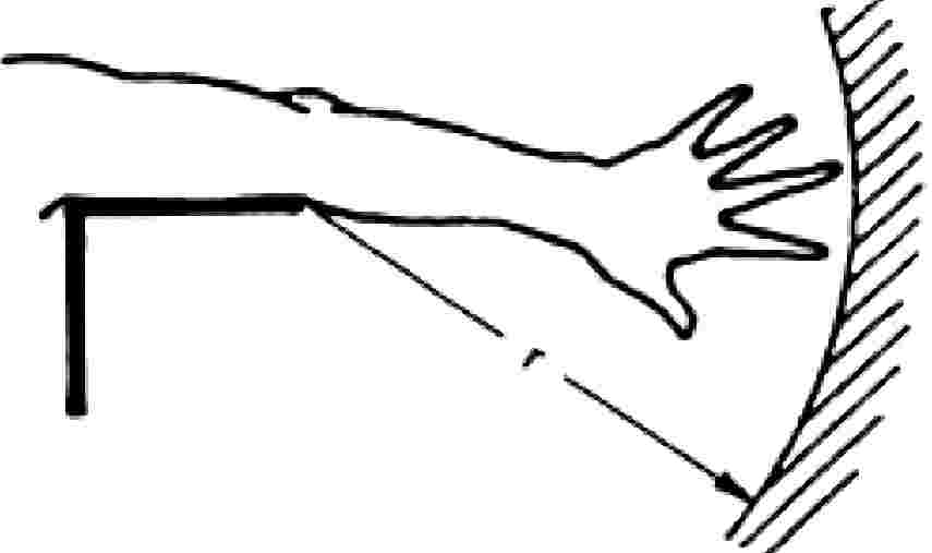
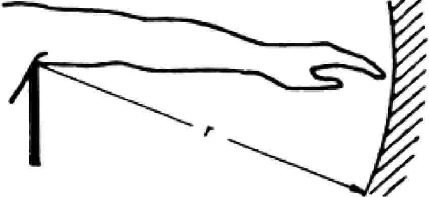
‘Reach’ means the maximum distance which can be reached by persons or certain parts of their bodies upwards, downwards, inwards, above, around or across without the aid of any object (Figure 1). |
|
2.2.4. |
‘Safety distance’ means the distance corresponding to the reach or to the body dimension plus a safety margin (Figure 1). |
|
2.2.5. |
‘Control’ means any device whose direct actuation enables the state or operation of the tractor or of any equipment linked to it to be altered. |
|
2.2.6. |
‘Normal operation’ means the use of the tractor for the purpose intended by the manufacturer and by an operator familiar with the tractor characteristics and complying with the information for operation, service and safe practices, as specified by the manufacturer in the operator's manual and by signs on the tractor. |
|
2.2.7. |
‘Inadvertent contact’ means unplanned contact between a person and a hazard location resulting from the person's action during normal operation and service of the tractor. |
2.3. Safety distances for avoiding contact with dangerous parts
|
2.3.1. |
The safety distance is measured from those points which may be reached to actuate, service and inspect the tractor, and also from ground level. ‘Servicing and inspecting the tractor’ solely means work normally carried out by the driver himself in accordance with the instructions for use. In determining the safety distances the basic principle is that the tractor is in the state for which it has been designed and that no means has been used in order to reach the dangerous part. Safety distances are set out in points 2.3.2.1 to 2.3.2.5. In certain specific areas or for certain specific component parts an appropriate safety level is provided if the tractor corresponds to the requirements set out in points 2.3.2.6 to 2.3.2.14. |
|
2.3.2. |
Protection of dangerous points 2.3.2.1. Upwards The upward safety margin is 2 500 mm (see Figure 1) in the case of persons standing upright. 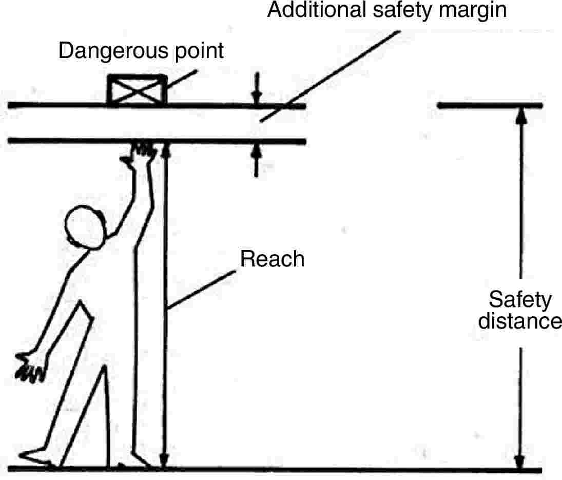
Figure 1 2.3.2.2. Downwards, above The safety margin for reaching above a barrier is:
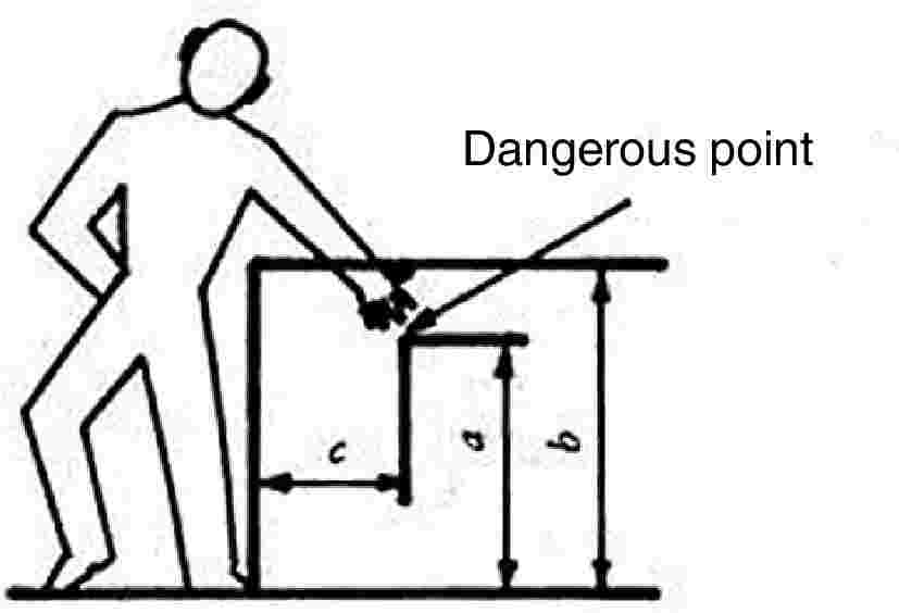
Figure 2 When reaching both downwards and above the safety distances set out in Table 1 must be maintained.
Table 1
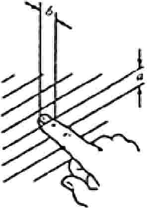
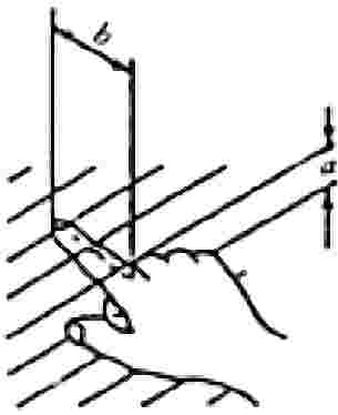
2.3.2.3. Reach around The safety margin shown in Table 2 below must, at the minimum, be maintained if the part of the body concerned is not to reach a dangerous point. In applying the safety margin it is assumed that the main body joint concerned is pushed firmly against the edge of the protective device. The safety margins are not considered to have been maintained until one is satisfied that part of the body may quite definitely not advance or penetrate further. Table 2
2.3.2.4. Penetration and reach across If penetration is possible into or across openings and up to dangerous parts, the minimum safety distances set out in Tables 3 and 4 must be maintained. Parts which move in relation to one another or moving parts set alongside fixed parts are not regarded as risk factors provided they are no more than 8 mm apart.
Table 3
Table 4
2.3.2.5. Safety distances at pinching points A pinching point is not considered dangerous for the part of the body shown if the safety distances are not less than those set out in Table 5, and if it is ensured that the adjacent, wider part of the body cannot be introduced.
Table 5
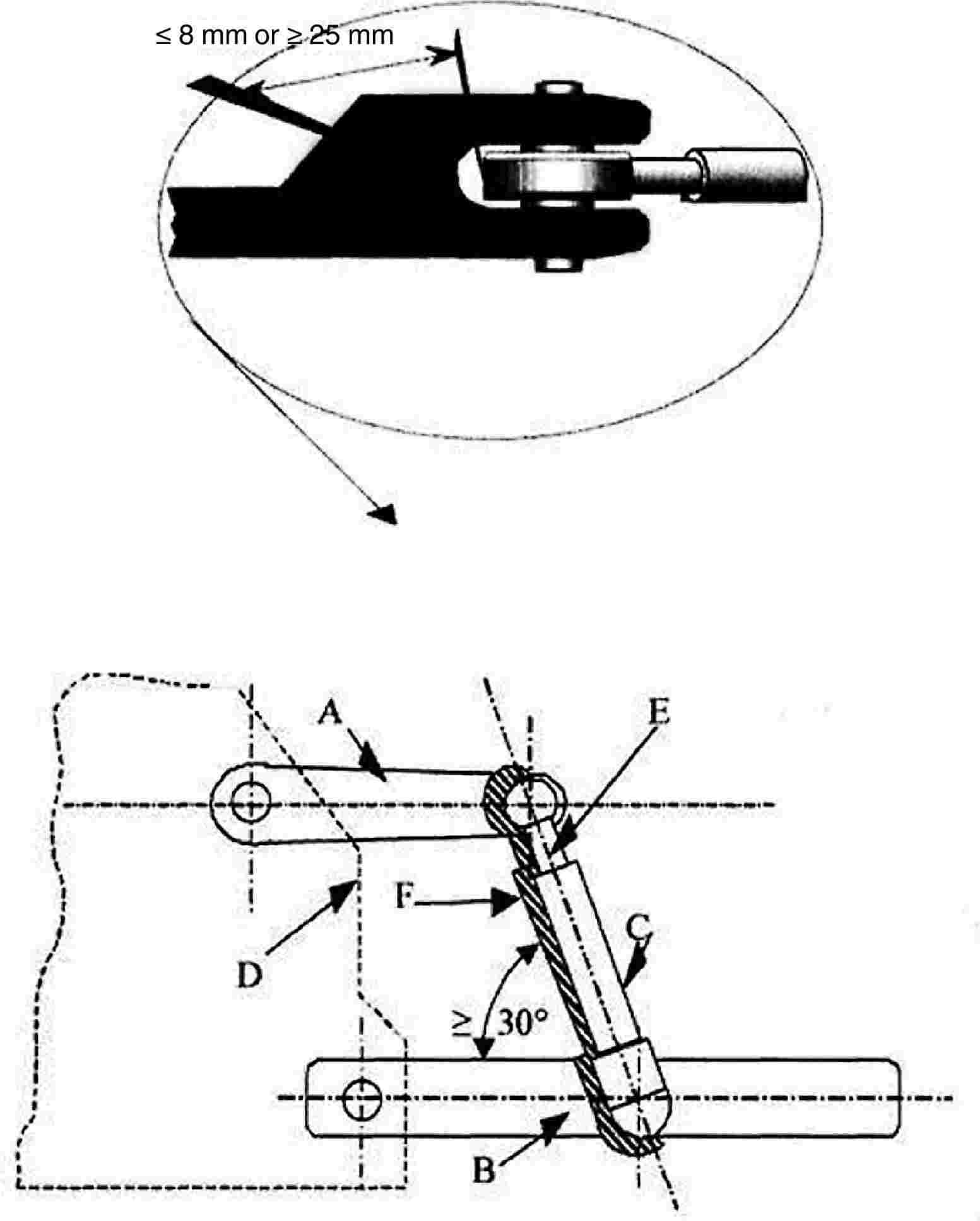
2.3.2.6. Controls The gap between two pedals and the holes through which controls pass are not regarded as being pinching or shearing points. 2.3.2.7. Rear three-point coupling
2.3.2.8. Front three-point coupling
2.3.2.9. Driving seat and environment When he is in a sitting position, all pinching or shearing points must be out of range of the driver's hands or feet. This requirement is considered to have been met if the following conditions are fulfilled:
2.3.2.10. Passenger seat (if any)
|
||||||||||||||||||||||||||||||||||||||||||||||||||||||||||||||||||||||||||||||||||||||||||||||||||||||||||||||||||||||||||||||||||||||||||||||||||||||||||||||||||||||||||||||||||||||||||||||||||||||||||||||||||||||||||||||||||||||||||||||||||||||||||||||||||||||||||||||||||||||||||||||||||||||||||||||||||||||||||||||||||||||||||||


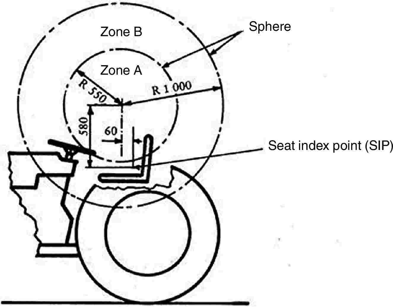
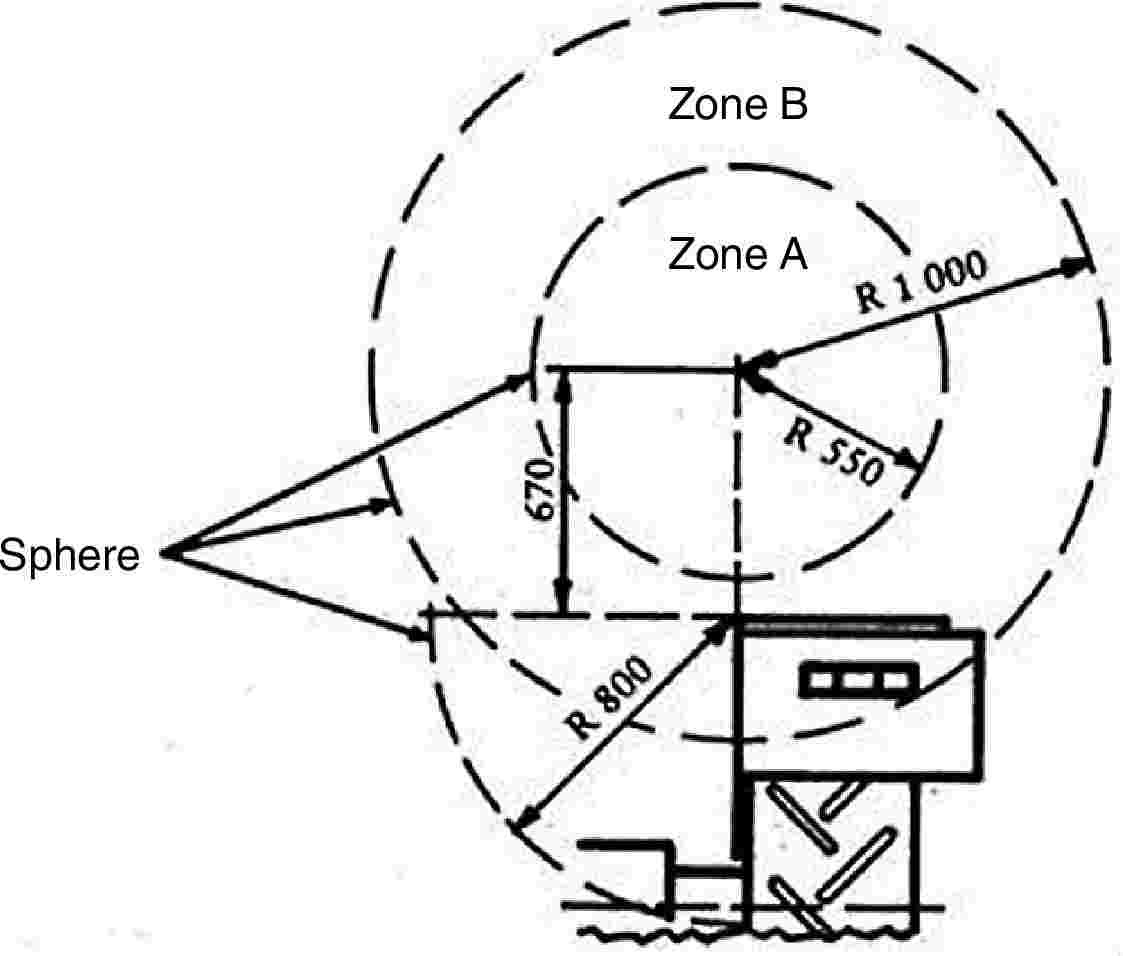

2.4. Method of determining the seat index point
2.4.1. General
The method and device used in defining the index point for any type of upholstered seat are described below.
2.4.2. Definitions
Seat index point (SIP):
Point situated in the vertical median longitudinal plane of the SIP locating device represented in Figure 10 which is placed on the driving seat in accordance with points 2.4.4 and 2.4.6.
The seat index point is established in relation to the vehicle and does not move as a function of the seat adjustments and/or oscillations.
2.4.3. Device for determining the seat index point (SIP)
The device for determining the SIP must be as shown in Figure 10. The mass of that device is 6 ± 1 kg and its underside must be flat and polished.
2.4.4. Seat setting for determination of index point (SIP)
Where a seat and its suspension can be regulated, the seat is regulated as follows before the index point is determined:
(a) all of the adjustments — back/forth, height and rake — must be in their mid-position. If this is not the case, the closest adjustment either above or below the mid-position should be used;
(b) adjustable suspension must be adjusted in such a way that the suspension is at mid-travel with the locating device in position and loaded. The suspension may be locked mechanically in that position while the index point (SIP) is determined;
(c) non-adjustable suspension may be locked in the vertical position that is achieved with the locating device in place and loaded;
(d) if the adjustments mentioned above conflict with the manufacturer's specific instructions, these must be followed in such a way as to obtain the setting recommended for a 75 kg driver.
NB: A 75 kg driver offers an approximation of the locating device in position on the seat and loaded with a mass of 65 kg.
2.4.5. Determination of the three reference axes x′, y′, and z′ for the SIP
The coordinates must be established as follows:
(a) location, on one side of the seat mounting, of the attachment hole that is in the most rear position;
(b) if the axis of this hole is parallel to the pivot axis defined on the device, it is taken as axis y′ (pointing from left to right in relation to a seated driver — see Figure 11);
(c) if the axis of this hole is parallel to the vertical plane passing through the centre line of the seat, the straight line is taken as axis y′ which runs parallel to the pivot axis referred to and passes through the point of intersection between the supporting plane of the seat and the hole axis referred to above (see Figure 12);
(d) in all other cases, axis y′ is established in accordance with the parameters relating to the seat being measured;
(e) axes x′ and z′ are defined as intersections of the horizontal and vertical planes passing through y′ with the vertical plane through the seat centre line. Axes x′ and z′ point forwards and upwards (see Figures 11 and 12).
2.4.6. Method of determining the seat index point (SIP)
The seat index point (SIP) is determined by using the device shown in Figure 10 and by proceeding in the following manner:
(a) the seat is covered with a piece of cloth in order to facilitate correct positioning of the device;
(b) the device is positioned on the seat cushion (without additional mass) by pushing it rearwards against the backrest;
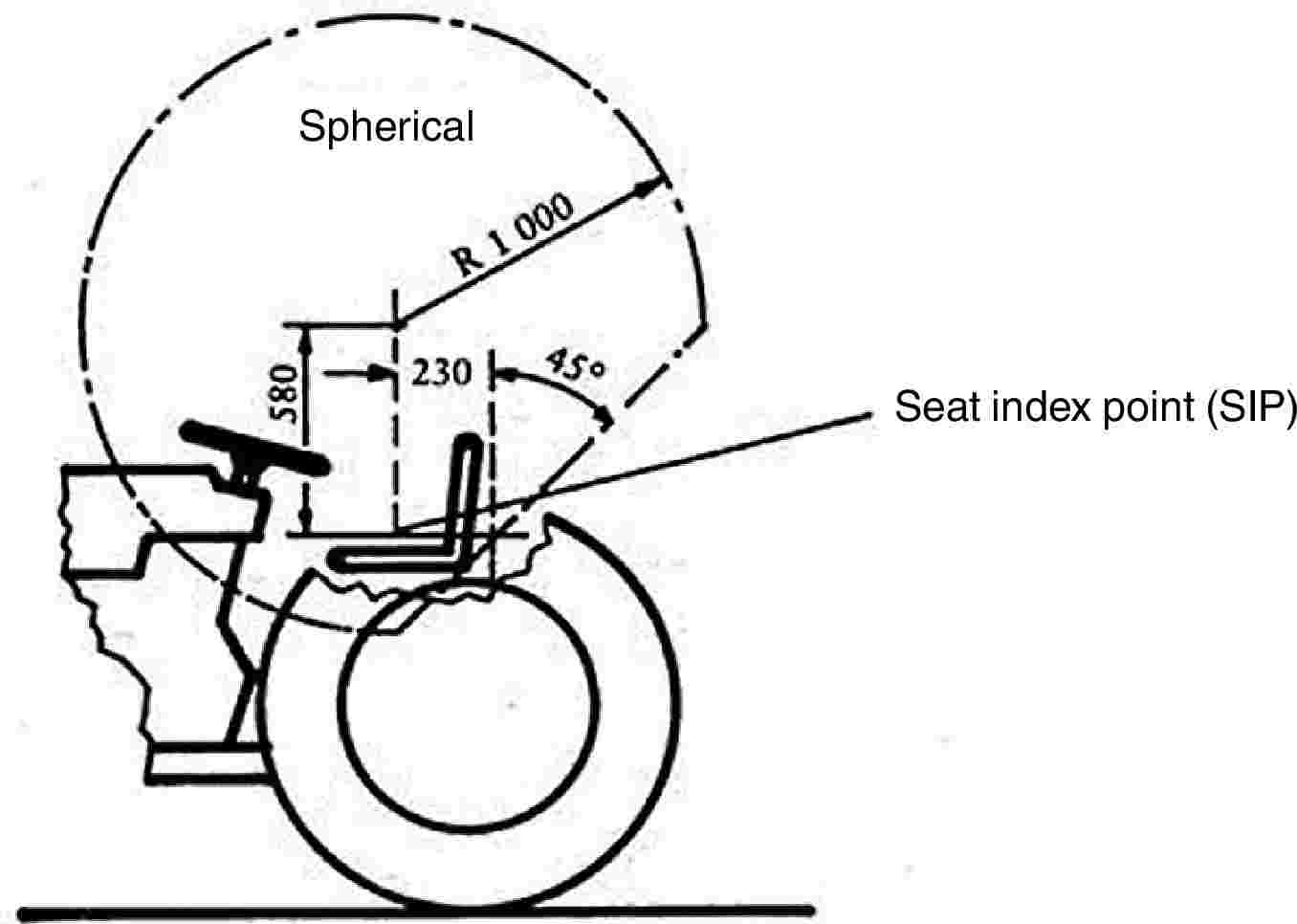
(c) masses are added to bring the total mass of the device from 6 ± 1 kg to 26 ± 1 kg. The centre of vertical force must be 40 mm ahead of the seat index point mark on the horizontal part of the device (see Figure 10);
(d) a horizontal force of about 100 N is applied twice to the device on the seat index point, as set out in figure 10;
(e) other masses are added to bring the total mass of the device from 26 ± 1 kg to 65 ± 1 kg. The centre of the vertical force of the masses added must be 40 mm ahead of the seat index point mark on the horizontal part of the device (see Figure 10);
(f) on both sides of the seat in two vertical planes, equidistant from the median longitudinal line of the seat, the coordinates, as defined in point 2.4.5, of the intersections of those planes on the axis of the seat index point marked by the device must be measured to ± 1 mm.
The arithmetical mean values of the measurements taken in the two planes are recorded as SIP coordinates;
(g) the conditions resulting from the method of determination, and which diverge from the procedure set out in this Annex, or which may be the source of errors as regards their results, may be noted, as may their causes.
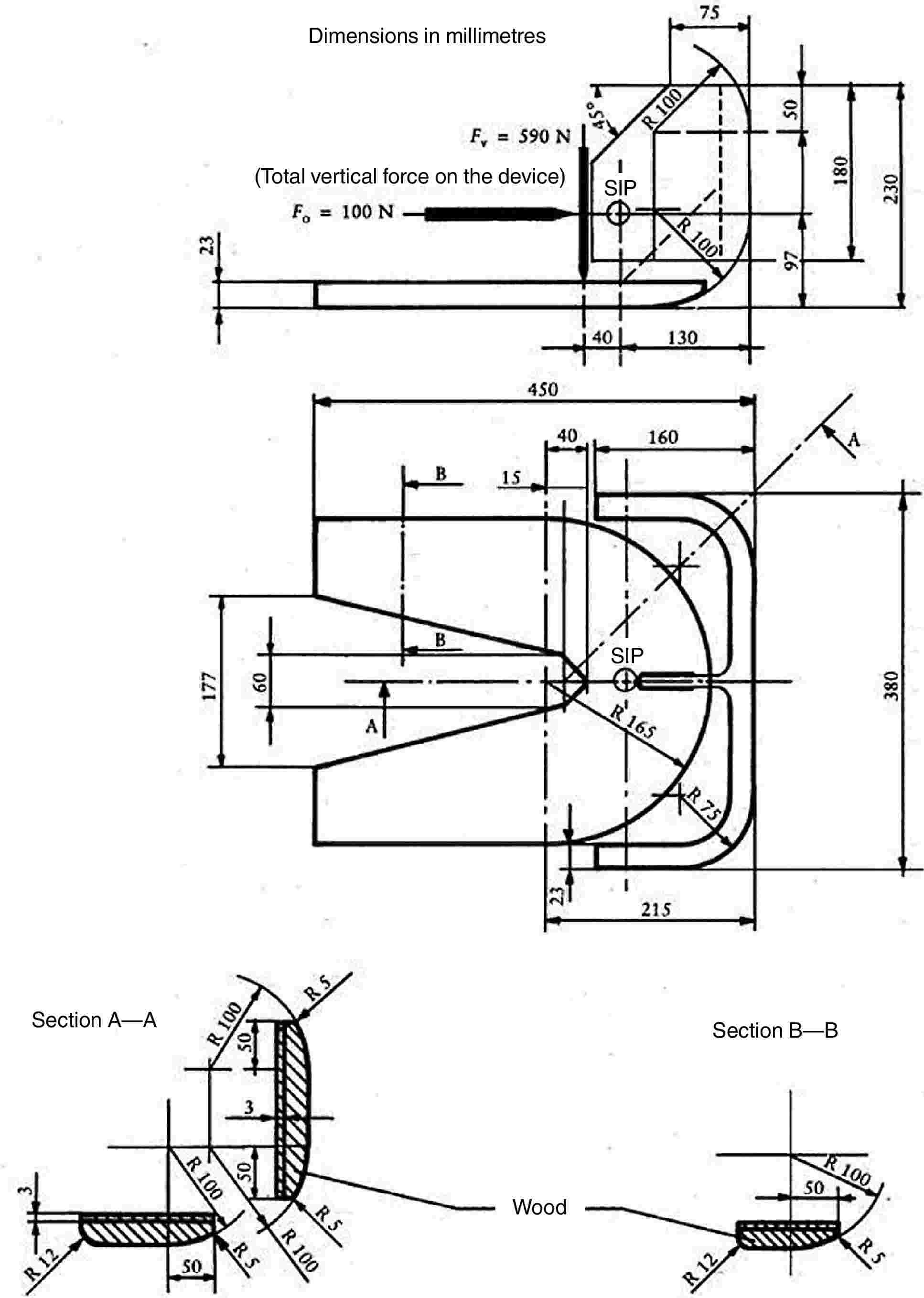
Figure 10 — Device for determining the seat index point (SIP)
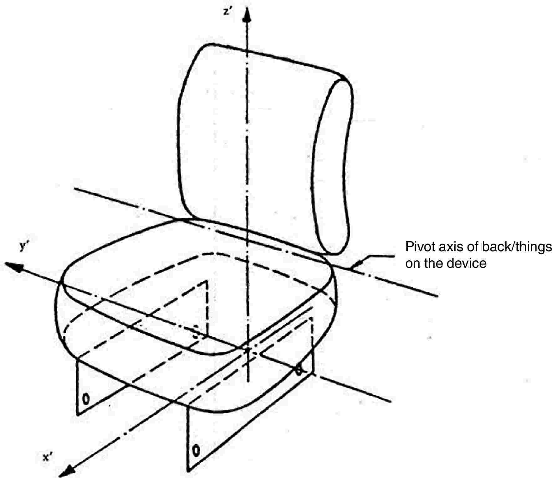
Figure 11 — Determination of SIP reference axes
(Axis of attachment hole parallel to the pivot axis of the back/thighs)
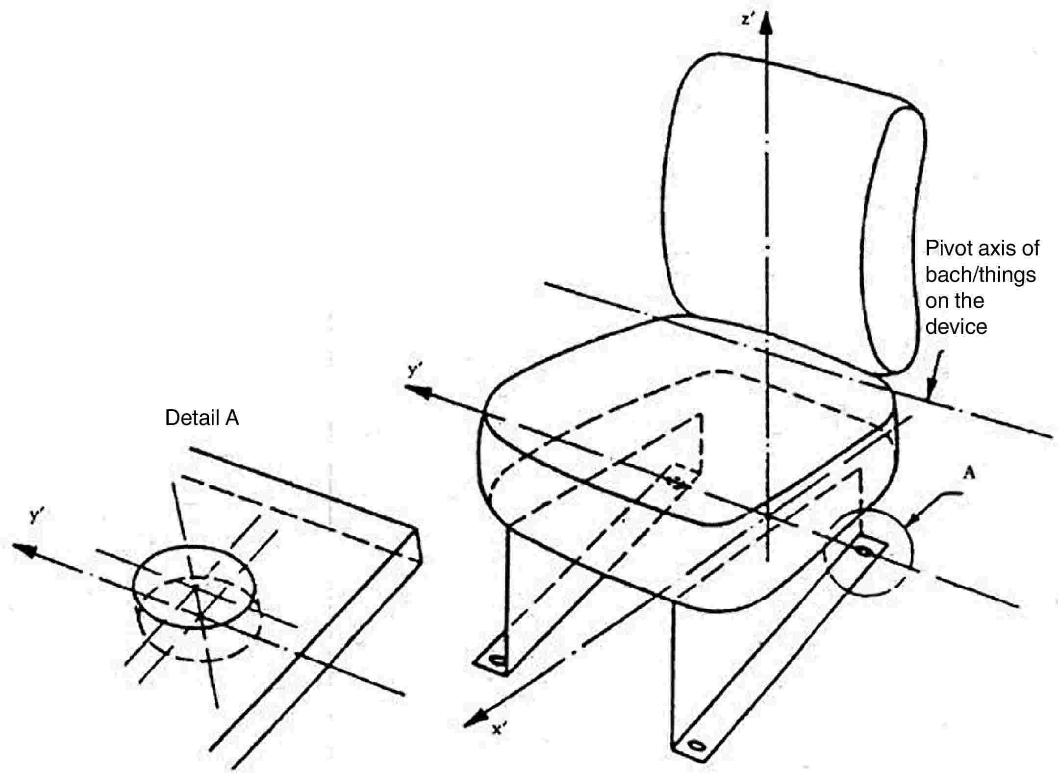
Figure 12 — Determination of the three reference axes of the SIP
(Axis of attachment hole parallel to the vertical plane passing through the median line of the seat)
3. ADDITIONAL SAFETY REQUIREMENTS FOR SPECIAL APPLICATIONS
3.1. Falling Objects Protective Structures
Falling Objects Protective Structures (FOPS), if provided, shall comply with OECD Code 10 ( 12 ).
3.2. Operators Protection Structures
|
3.2.1. |
Operators Protection Structures (OPS), if provided, shall comply with ISO 8084:2003 ( 13 ). |
|
3.2.2. |
For other than forestry applications and without prejudice to point 3.2.1, tractors with glazing according to point 1.1.3 of Annex III A shall be considered to be equipped with Operators Protection Structures (OPS). |
3.3. Prevention of Contact with Hazardous Substances
The requirements of EN 15695-1:2009 shall apply to all tractors defined in Article 2(j) of Directive 2003/37/EC, if they are being used in conditions which may cause the risk of contact with hazardous substances; in such case the cabin has to fulfil the requirements of level 2, 3 or 4 of this standard. The criteria for the choice between the levels must be described and be in line with those indicated in the operator’s manual. For spraying of pesticides the cabin must be of level 4.
4. OPERATOR’S MANUAL
The operator’s manual shall comply with ISO 3600:1996 ( 14 ) with the exception of section 4.3 (Machine identification).
|
4.1. |
In particular or in addition to the requirements in standard ISO 3600:1996, the operator’s manual shall cover the following: (a) adjustment of the seat and suspension related to the ergonomic position of the operator with respect to the controls and in order to minimise the risks from whole body vibration; (b) use and adjustment of the system for heating, ventilation and air-conditioning, when provided; (c) starting and stopping of the engine; (d) location and method of opening of emergency exits; (e) boarding and leaving the tractor; (f) the hazard area near to the pivot axis of articulated tractors; (g) use of special tools, if any are provided; (h) safe methods used for service and maintenance; (i) information about the interval of inspection of hydraulic hoses; (j) instructions about how to tow the tractor; (k) instructions about the safe use of jacks and recommended jacking points; (l) hazards related to batteries and fuel tank; (m) prohibited use of the tractor, where overturning hazards exist with mention that the list is not exhaustive; (n) residual risks, related to hot surfaces, such as filling of oil or coolant in hot engines or transmissions; (o) the level of protection of the Falling Objects Protective Structure, if applicable; (p) the level of protection against hazardous substances, if applicable; (q) the level of protection of the Operators Protection Structure, if applicable. |
|
4.2. |
Attaching, detaching and working with mounted machinery, trailers and interchangeable towed machinery
The operator’s manual shall include the following: (a) a warning to strictly follow the instructions outlined in the operator’s manual of the mounted or trailed machinery or trailer, and not to operate the combination tractor — machine or tractor — trailer unless all instructions have been followed; (b) a warning to stay clear from the area of the three-point linkage when controlling it; (c) a warning that mounted machinery must be lowered on the ground before leaving the tractor; (d) speed of the power take-off drive shafts in function of the mounted machinery or trailed vehicle; (e) a requirement to use only power take-off drive shafts with adequate guards; (f) information about hydraulic coupling devices and their function; (g) information about the maximum lift capacity of the three-point linkage; (h) information about the determination of the total mass, the axle loads, the tyre load carrying capacity and the necessary minimum ballasting; (i) information about the available trailer braking systems and their compatibility with the trailed vehicles; (j) the maximum vertical load on the rear hitch, related to the rear tyre size and type of hitch; (k) information about using implements with power take-off drive shafts and that the technically possible inclination of the shafts depend on the shape and size of the master shield and/or clearance zone, including the specific information required in case of PTO type 3 with reduced dimension; (l) a repeat of the data on the statutory plate about maximum allowed trailed masses; (m) a warning to stay clear from the area between tractor and trailed vehicle. |
|
4.3. |
Noise declaration
The operator’s manual shall give the value of the noise at the operator’s ear, measured according to Directive 2009/76/EC ( 15 ) of the European Parliament and of the Council and the noise of the tractor in motion measured according to Annex VI to Directive 2009/63/EC ( 16 ) of the European Parliament and of the Council. |
|
4.4. |
Vibration declaration
The operator’s manual shall give the value of the vibration level measured according to Council Directive 78/764/EEC ( 17 ). |
|
4.5. |
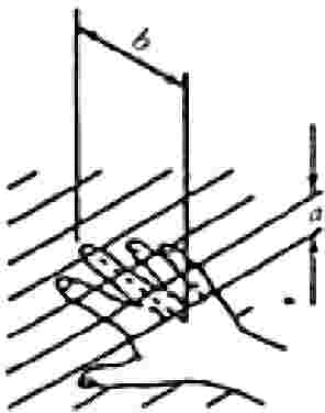
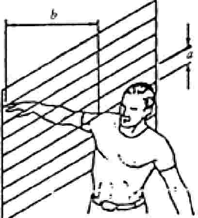
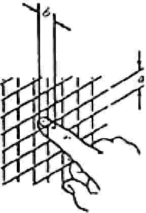
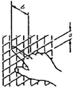
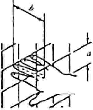
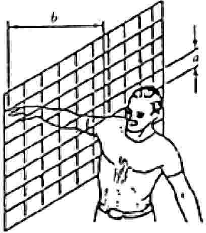
Relevant operating modes of a tractor that can reasonably be expected and identified as containing particular hazards are the following: (a) work with front-end loader (risk of falling objects); (b) forestry application (risk of falling and/or penetrating objects); (c) work with crop sprayers, mounted or trailed (risk of hazardous substances). Particular attention shall be given in the operator’s manual to the use of the tractor in combination with the above equipment. 4.5.1. Front–end loader 4.5.1.1. The operator’s manual shall outline the hazards associated with front-end loader work, and explain how to avoid those hazards. 4.5.1.2. The operator’s manual shall indicate the fixation points on the body of the tractor where the front–end loader must be installed, together with the size and quality of the hardware to be used. If no such attachment points are foreseen, the operator’s manual shall prohibit the installation of a front–end loader. 4.5.1.3. Tractors fitted with programmable hydraulic sequencing functions shall provide information on how to connect the loader hydraulics so that this function is inoperable. 4.5.2. Forestry application 4.5.2.1. In case of use of an agricultural tractor in a forestry application, the identified hazards are the following: (a) toppling trees, primarily in case a rear-mounted tree grab-crane is mounted at the rear of the tractor; (b) penetrating objects in the operator’s enclosure, primarily in case a winch is mounted at the rear of the tractor. 4.5.2.2. The operator’s manual shall provide information about the following: (a) the existence of the hazards described in point 4.5.2.1; (b) any optional equipment that might be available to deal with those hazards; (c) fixation points on the tractor where protective structures can be fixed, together with the size and quality of the hardware to be used; when no means are foreseen to fit adequate protective structures, this shall be mentioned; (d) protective structures may consist of a frame protecting the operating station against toppling trees or (mesh) grids in front of the cab doors, roof and windows; (e) the Falling Objects Protection System level, if provided. 4.5.3. Work with crop sprayers (risk of hazardous substances) The protection level against hazardous substances, in accordance with EN 15695-1:2009, must be described in the operator’s manual. |
Appendix
MODEL
ANNEX TO THE EC TYPE-APPROVAL CERTIFICATE FOR A TRACTOR TYPE WITH REGARD TO THE SPEED GOVERNOR AND PROTECTION OF DRIVE COMPONENTS, PROJECTIONS AND WHEELS, ADDITIONAL SAFETY REQUIREMENTS FOR SPECIAL APPLICATIONS, OPERATOR’S MANUAL
(Article 4(2) of Directive 2003/37/EC of the European Parliament and of the Council of 26 May 2003 on type-approval of agricultural or forestry tractors, their trailers and interchangeable towed machinery, together with their systems, components and separate technical units)
EC type-approval No: …
|
1. |
Component(s) or characteristic(s):
|
|
2. |
Make of tractor (or business name of manufacturer): … … |
|
3. |
Type and where appropriate commercial name of tractor: … … |
|
4. |
Manufacturer's name and address: … … |
|
5. |
If applicable, name and address of manufacturer's authorised representative: … … |
|
6. |
Description of component(s) and/or characteristic(s) mentioned under 1 above: … |
|
7. |
Date of submission of tractor for EC type-approval: … |
|
8. |
Technical service conducting the type-approval tests: … … |
|
9. |
Date of report issued by that service: … |
|
10. |
Number of report issued by that service: … |
|
11. |
EC type-approval for the speed governor and protection of the drive components, projections and wheels is granted/refused ( 18 ): |
|
12. |
Place: … |
|
13. |
Date: … |
|
14. |
Signature: … |
|
15. |
The following documents, bearing the EC type-approval number indicated above, are attached to this certificate: … dimensioned drawings; … drawing or photograph of the relevant parts of the tractor; … operator’ s manual. The data must be supplied to the competent authorities of the other Member States if they so request. |
|
16. |
Remarks: … … |
ANNEX III A
Windscreen and other glazing Equipment requirements, definitions, application for component type-approval, component type-approval, markings, general specifications, tests and conformity of production
1. EQUIPMENT REQUIREMENTS
|
1.1. |
Agricultural and forestry tractors may be equipped as chosen by their manufacturer with:
|
2. DEFINITIONS
For the purposes of this Directive:
|
2.1. |
‘toughened-glass pane’ means a glass pane consisting of a single layer of glass which has been subjected to special treatment to increase its mechanical strength and condition its fragmentations after shattering; |
|
2.2. |
‘laminated-glass pane’ means a glass pane consisting of two or more layers of glass held together by one or more interlayers of plastic material; it may be:
|
|
2.3. |
‘safety glazing coated with plastic material’ means a glass pane as defined in point 2.1 or 2.2 with a layer of plastic material on its inner surface; |
|
2.4. |
‘glass-plastic safety glazing’ means a pane of laminated glass having one layer of glass and one or more layers of plastic material at least one of which acts as interlayer. The plastic layers shall be on the inner face when the glazing is fitted on the tractor; |
|
2.5. |
‘group of windscreens’ means a group comprising windscreens of differing sizes and shapes subjected to an examination of their mechanical properties, their mode of fragmentation and their behaviour in environmental resistance tests;
|
|
2.6. |
‘double window’ means a set of two panes installed separately in the same opening on the tractor; |
|
2.7. |
‘double glazing’ means a unit composed of two panes permanently assembled in the factory and separated by a uniform gap;
|
|
2.8. |
‘principal characteristic’ means a characteristic which appreciably modifies the optical and/or mechanical properties of a pane of glass in a way not without significance to the function which the glass pane is to perform in a tractor. This term also covers the trade name or mark; |
|
2.9. |
‘secondary characteristic’ means a characteristic capable of modifying the optical and/or mechanical properties of a pane of glass in a way which is of significance to the function which the glass pane is intended to perform in a tractor. The extent of such modification is assessed in relation to the indices of difficulty; |
|
2.10. |
‘indices of difficulty’ covers a two-stage grading system applying to the variations observed in practice in each secondary characteristic. A change from index ‘1’ to index ‘2’ indicates the need for additional tests; |
|
2.11. |
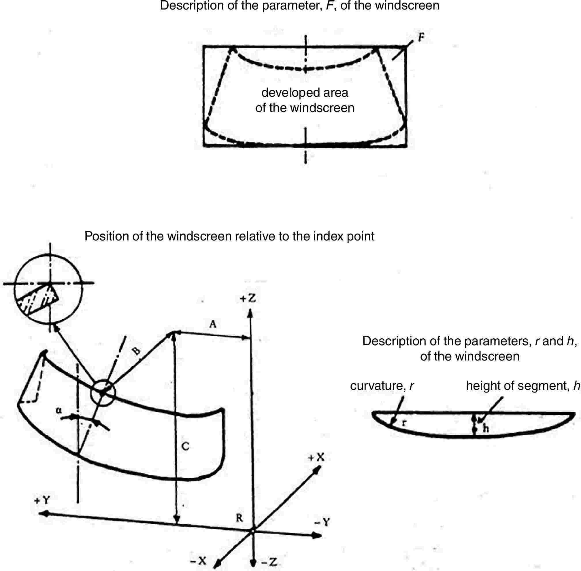
‘developed area of a windscreen’ means the minimum rectangular area of glass from which a windscreen can be manufactured; |
|
2.12. |
‘rake angle of a windscreen’ means the angle included between a vertical line and a straight line passing through the top and bottom extremities of the windscreen, both lines lying in a vertical plane along the longitudinal axis of the tractor.
|
|
2.13. |
‘height of segment, h’ means the maximum distance, measured at right angles approximately to the glass pane, separating the inner surface of the pane from a pane passing through the ends of the pane (see Annex III N, Figure 1); |
|
2.14. |
‘type of glass pane’ means a glass pane, as defined in points 2.1 to 2.4, not exhibiting any essential differences in respect, in particular, of the principal and secondary characteristics mentioned in Annexes III D to III L.
|
|
2.15. |
‘curvature, r’ means the approximate value of the smallest radius of arc of the windscreen as measured in the area of maximum curvature. |
3. APPLICATION FOR COMPONENT TYPE-APPROVAL
|
3.1. |
The application for EC component type-approval for a type of glass pane is submitted by the manufacturer of the safety-glass pane or by his duly accredited representative for each type of safety glass. The application may be made in one Member State only. |
|
3.2. |
For each type of safety glass, the application is accompanied by the undermentioned documents in triplicate and by the following particulars:
|
|
3.3. |
In addition, the applicant must submit a sufficient number of test pieces and samples of the finished glass panes of the models considered, the number being if necessary determined by agreement with the technical service responsible for conducting the tests. |
|
3.4. |
The competent authority must verify the existence of satisfactory arrangements for ensuring effective control of conformity of production before component type-approval is granted. |
4. MARKINGS
|
4.1. |
Every safety-glass pane, including the samples and test-pieces submitted for component type-approval, must bear the trade name or mark of the manufacturer. The marking must be clearly legible and indelible. |
5. COMPONENT TYPE-APPROVAL
|
5.1. |
If the samples submitted for component type-approval meet the requirements of points 5 to 7 below, approval of the pertinent type of safety-glass pane is granted. |
|
5.2. |
A component type-approval number is assigned to each type as defined in Annexes III E, III G, III K and III L, or, in the case of windscreens, to each group approved. Its first two digits (at present 00 for Directive 89/173/EEC in its original form) indicate the series of amendments incorporating the most recent major technical amendments made to Directive 89/173/EEC as replaced by this Directive at the time of issue of the approval. A Member State may not assign the same number to another type or group of safety-glass panes. |
|
5.3. |
Component type-approval or extension or refusal of approval for a type of safety-glass pane pursuant to this Directive is communicated to the Member States by means of a notice prepared in accordance with the model set out in Annex III B to this Directive and its Appendices.
|
|
5.4. |
In addition to the marking specified in point 4.1, an EC component type-approval mark must be affixed conspicuously to all safety-glass panes and double-glazed units conforming to a type approved under this Directive. Any special component type-approval mark assigned to each pane of a double-glazed unit may also be affixed. This component type-approval mark consists of:
|
|
5.5. |
The following additional symbols are affixed near the above EC type-approval mark:
|
|
5.6. |
The EC component type-approval mark and the symbol must be clearly legible and indelible. |
|
5.7. |
The Appendix to this Annex gives examples of component type-approval marks. |
6. GENERAL REQUIREMENTS
|
6.1. |
All glass panes, and particularly those intended for the manufacture of windscreens, must be of sufficient quality to reduce the risk of bodily injury as far as possible in the event of the glass shattering. The glass must be sufficiently resistant to the incidents likely to occur in normal traffic, and to atmospheric and temperature conditions, chemical action, combustion and abrasion. |
|
6.2. |
Safety glass must in addition be sufficiently transparent, must not cause any noticeable distortions of objects as seen through the windscreen, and must not give rise to any confusion between the colours used in road-traffic signs and signals. In the event of the windscreen shattering, the driver must still be able to see the road clearly enough to be able to brake and stop his tractor safely. |
7. PARTICULAR REQUIREMENTS
All types of safety glass must, depending on the category to which they belong, comply with the following particular requirements:
|
7.1. |
as regards toughened-glass windscreens, the requirements contained in Annex III D; |
|
7.2. |
as regards uniformly toughened glass panes other than windscreens, the requirements contained in Annex III E; |
|
7.3. |
as regards ordinary laminated-glass windscreens, the requirements contained in Annex III F; |
|
7.4. |
as regards ordinary laminated-glass panes other than windscreens, the requirements contained in Annex III G; |
|
7.5. |
as regards treated laminated-glass windscreens, the requirements contained in Annex III H; |
|
7.6. |
as regards safety-glass panes faced with plastic material, in addition to the relevant requirements listed above, the requirements contained in Annex III I; |
|
7.7. |
as regards glass-plastic windscreens, the requirements contained in Annex III J; |
|
7.8. |
as regards glass-plastic panes other than windscreens, the requirements contained in Annex III K; |
|
7.9. |
as regards double-glazed units, the requirements contained in Annex III L. |
8. TESTS
|
8.1. |
The following tests are prescribed: 8.1.1. Fragmentation The purpose of this test is:
8.1.2. Mechanical strength 8.1.2.1. Ball-impact test This test takes two forms, one using a 227 g ball and the other a 2 260 g ball.
8.1.2.2. Headform test The purpose of this test is to verify the glass pane's compliance with requirements relating to the limitation of injury in the event of impact of the head against the windscreen, laminated glass or glass-plastic panes other than windscreens, and also double-glazed units used as side windows. 8.1.3. Resistance to the environment 8.1.3.1. Abrasion test The purpose of this test is to determine whether the resistance of a safety-glass pane to abrasion exceeds a specified value. 8.1.3.2. High-temperature test The purpose of this test is to verify that no bubbles or other defects occur in the interlayer in a laminated glass or glass-plastic pane when the latter is exposed to high temperatures over an extended period of time. 8.1.3.3. Resistance-to-radiation test The purpose of this test is to determine whether the light transmittance of laminated-glass, glass-plastic or plastic-coated glass panes exposed to radiation over an extended period of time is significantly reduced thereby or whether the glazing is significantly discoloured. 8.1.3.4. Resistance-to-humidity test The purpose of this test is to determine whether a laminated-glass, glass-plastic or plastic-coated glass pane will withstand, without significant deterioration, the effects of prolonged exposure to atmosphere humidity. 8.1.3.5. Resistance to temperature change The purpose of this test is to determine whether the plastic material(s) used in safety glazing as defined in points 2.3 and 2.4 will withstand, without significant deterioration, the effects of prolonged exposure to extreme temperatures. 8.1.4. Optical qualities 8.1.4.1. Light-transmission test The purpose of this test is to determine whether the regular transmittance of safety-glass panes exceeds a specified value. 8.1.4.2. Optical-distortion test The purpose of this test is to verify that the distortion of objects as seen through the windscreen is not such as to be likely to confuse the driver. 8.1.4.3. Secondary-image-separation test The purpose of this test is to verify that the angular separation of the secondary image from the primary image does not exceed a specified value. 8.1.4.4. Identification-of-colours test The purpose of this test is to verify that there is no risk of confusion of colours as seen through a windscreen. 8.1.5. Fire-resistance test The purpose of this test is to verify that the inner face of a safety-glass pane as defined in points 2.3 and 2.4 has a sufficiently low burn rate. 8.1.6. Resistance to chemical agents The purpose of this test is to determine that the inner face of a safety-glass pane as defined in points 2.3 and 2.4 will withstand the effects of exposure to chemicals likely to be present or used within the tractor (e.g. cleaning compounds) without deterioration. |
|
8.2. |
Tests prescribed for glass panes of the categories defined in points 2.1 to 2.4
|
|||||||||||||||||||||||||||||||||||||||||||||||||||||||||||||||||||||||||||||||||||||||||||||||||||||||||||||||||||||||||||||||||||||||||||||||||||||||||||||||||||||||||||||||||||||||||||||||||||||||||||||||||||||||||||||||||||||||||||||||||
9. MODIFICATION OR EXTENSION OF APPROVAL FOR A TYPE OF SAFETY-GLASS PANE
|
9.1. |
All modifications to a type of safety-glass pane, or, in the case of windscreens, all additions of windscreens to a group, must be notified to the administrative department which approved the type of safety-glass pane. The department may then either:
|
|
9.2. |
Communication
|
10. CONFORMITY OF PRODUCTION
|
10.1. |
Safety glazing granted type-approval under this and the following Annexes must be so manufactured as to conform to the approved type and meet the requirements set out in points 6, 7 and 8. |
|
10.2. |
To verify that the requirements of point 10.1 have been met, constant checks must be carried out on production. |
|
10.3. |
The holder of the component type-approval must in particular:
|
|
10.4. |
The competent authority may at any time verify the methods for checking conformity applicable to each production unit (see point 1.3 of Annex III O).
|
11. PENALTIES FOR NON-CONFORMITY OF PRODUCTION
|
11.1. |
Component type-approval granted in respect of a type of safety-glass pane pursuant to this Directive may be withdrawn if the requirement laid down in point 10.1 is not complied with. |
|
11.2. |
If a Member State withdraws an approval it has previously granted, it must forthwith notify the other Member States thereof by means of a copy of the component type-approval certificate with ‘COMPONENT TYPE-APPROVAL WITHDRAWN’ added in large letters at the bottom of the certificate, and signed and dated. |
12. PRODUCTION DEFINITELY DISCONTINUED
If the holder of component type-approval completely ceases to manufacture a type of safety-glass pane approved in accordance with this Directive, he must inform thereof the authority which granted the approval. That authority must in turn notify the other Member States thereof, by means of a copy of the compound type-approval notice conforming to the model shown in Annex III B.
13. NAMES AND ADDRESSES OF THE TECHNICAL SERVICES RESPONSIBLE FOR CONDUCTING COMPONENT TYPE-APPROVAL TESTS AND OF THE ADMINISTRATIVE DEPARTMENTS GRANTING SUCH APPROVAL
Each Member State must communicate to the other Member States and the Commission the names and addresses of the technical services responsible for conducting component type-approval tests and of the administrative departments granting EC component type-approval, to which the component type-approval certificate and certificates indicating refusal or withdrawal of component type-approval issued in the other Member States are to be sent.
Appendix
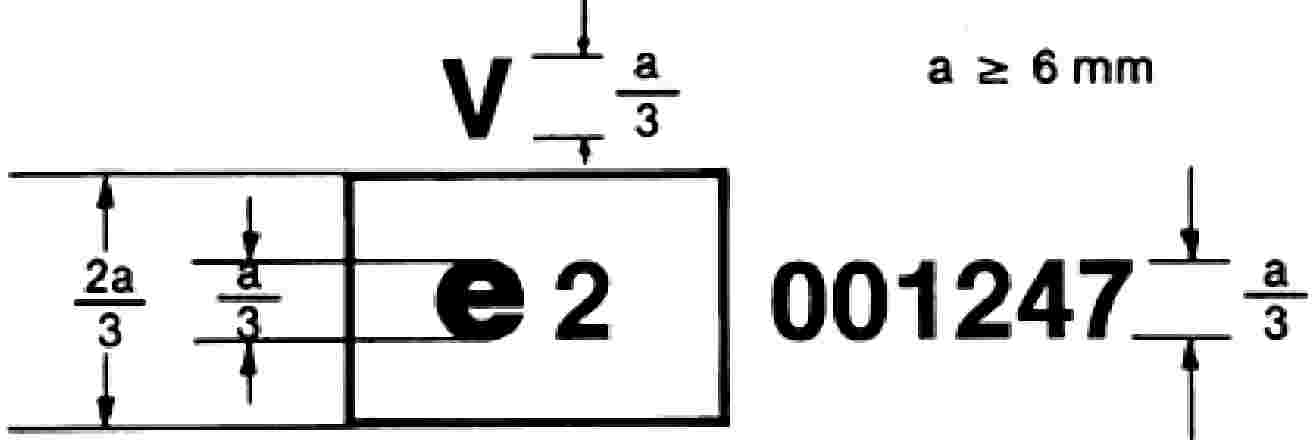
EXAMPLES OF COMPONENT TYPE-APPROVAL MARKS
(See point 5.5 of Annex III A)
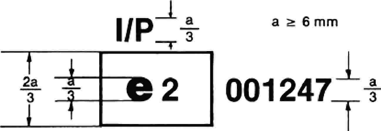
Toughened-glass windscreens:

The above component type-approval mark, affixed to a toughened-glass windscreen, shows that the component concerned was approved in France (e 2) pursuant to this Directive under component type-approval number 001247.
Toughened-glass windscreens faced with plastic material:
The above component type-approval mark affixed to a toughened-glass windscreen faced with plastic material shows that the component concerned was approved in France (e 2) pursuant to this Directive under component type-approval number 001247.
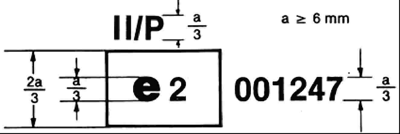
Ordinary laminated-glass windscreens:

The above component type-approval mark affixed to an ordinary laminated-glass windscreen shows that the component concerned was approved in France (e 2) pursuant to this Directive under component type-approval number 001247.
Ordinary laminated-glass windscreens faced with plastic material:
The above component type-approval mark affixed to an ordinary laminated-glass windscreen faced with plastic material shows that the component concerned was approved in France (e 2) pursuant to this Directive under component type-approval number 001247.
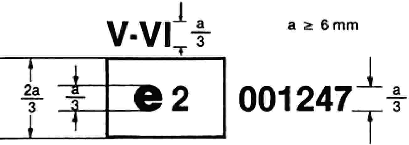
Treated laminated-glass windscreens:
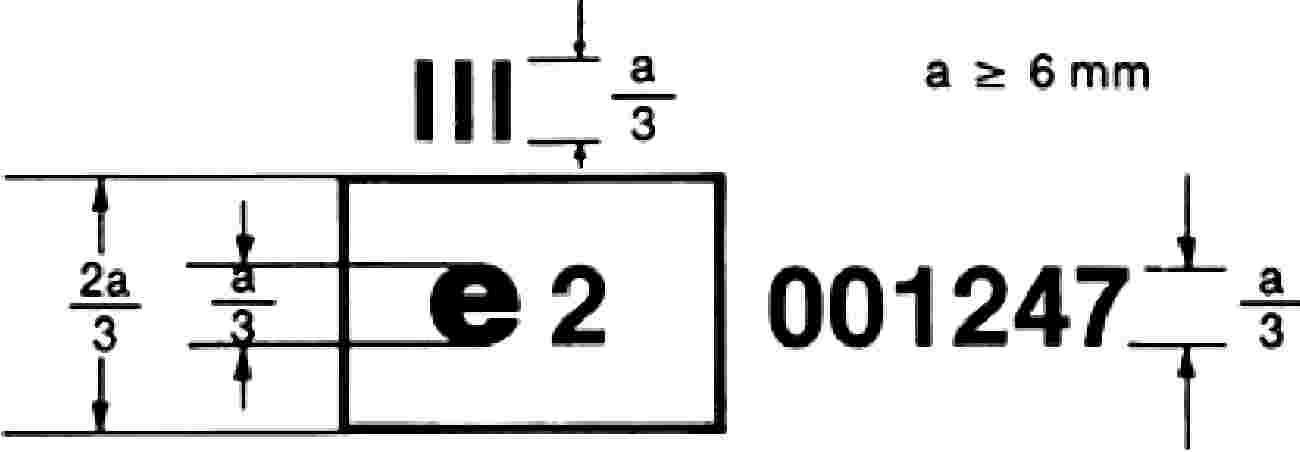
The above component type-approval mark affixed to a treated laminated-glass windscreen shows that the component concerned was approved in France (e 2) pursuant to this Directive under component type-approval number 001247.
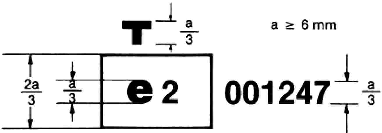
Glass-plastic windscreens:

The above component type-approval mark affixed to a glass-plastic windscreen shows that the component concerned was approved in France (e 2) pursuant to this Directive under component type-approval number 001247.
Glass panes other than windscreens having a regular light transmittance of less than 70 %:
The above component type-approval mark affixed to a glass pane other than a windscreen to which the requirements of point 9.1.4.2 of Annex III C are applicable shows that the component concerned was approved in France (e 2) pursuant to this Directive under component type-approval number 001247.
Double-glazed units having a regular light transmittance of less than 70 %:
The above component type-approval mark affixed to a double-glazed unit shows that the component concerned was approved in France (e 2) pursuant to this Directive under component type-approval number 001247.
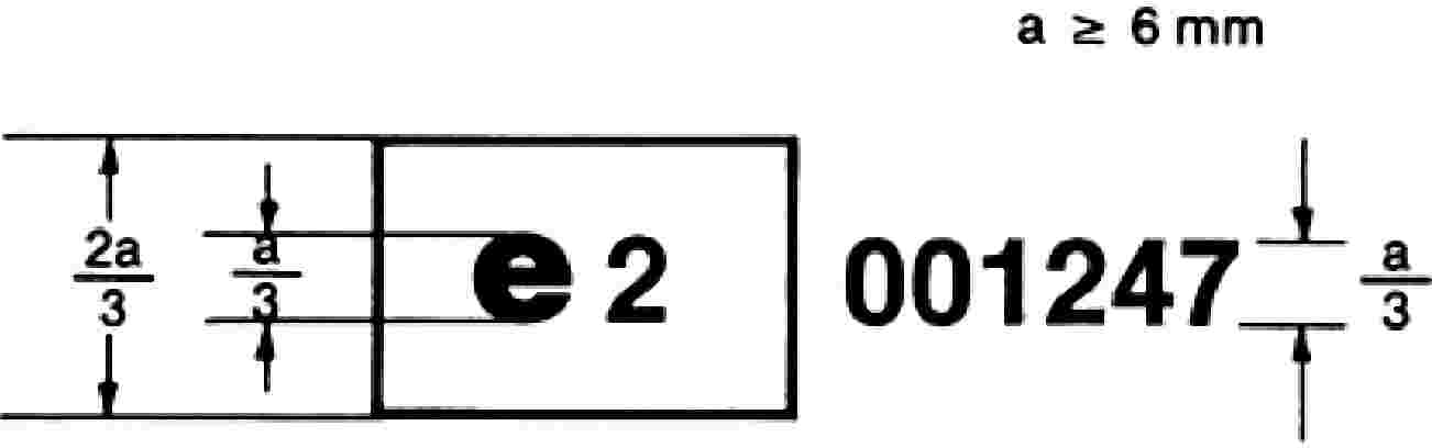
Glass panes other than windscreens to be used as windscreens for tractors:
The above component type-approval mark affixed to a glass pane shows that the component concerned intended to be used as a windscreen on a tractor was approved in France (e 2) pursuant to this Directive under component type-approval number 001247.
Glass panes other than windscreens having a regular light transmittance of 70 % more:
The above component type-approval mark affixed to a glass pane other than a windscreen to which the requirements of point 9.1.4.1 of Annex III C are applicable shows that the component concerned was approved in France (e 2) pursuant to this Directive under component type-approval number 001247.
ANNEX III B
(Maximum format: A4 (210 × 297 mm))
Communication on
— EC component type-approval,
— refusal of component type-approval,
— extension of component type-approval,
— withdrawal of component type-approval ( 24 ) for a type of safety-glass pane pursuant to Directive 2009/144/EC
EC component type-approval No: … Extension No …
|
1. |
Category of safety-glass pane: … |
|
2. |
Description of glass pane (see Appendices 1, 2, 3, 4, 5, 6, 7 (24) ) and, in the case of windscreens, the list conforming with Appendix 8: … … |
|
3. |
Trade name or mark: … |
|
4. |
Manufacturer's name and address: … … |
|
5. |
Name and address of manufacturer's representative where applicable: … |
|
6. |
Submitted for component type-approval on: … |
|
7. |
Technical service responsible for conducting component type-approval tests: … |
|
8. |
Date of test report: … |
|
9. |
Number of test report: … |
|
10. |
Component type-approval granted/refused/extended/withdrawn (24) : … |
|
11. |
Grounds for extending type-approval: … … … |
|
12. |
Remarks: … … … |
|
13. |
Place: … |
|
14. |
Date: … |
|
15. |
Signature: … |
|
16. |
A list is attached of the documents comprising the component type-approval file lodged with the administrative department granting the approval; these documents are available on request. |
Appendix 1
TOUGHENED-GLASS WINDSCREENS
(Principal and secondary characteristics as defined in Annex III D or III I)
Component type-approval No: … Extension No: …
Principal characteristics
— Shape category: …
— Thickness category: …
— Nominal thickness of the windscreen: …
— Nature and type of plastic coating(s): …
— Thickness of plastic coating(s): …
Secondary characteristics
— Nature of the material (plate, float, sheet glass):
— Colouring of glass: …
— Colouring of plastic coating(s): …
— Conductors incorporated (yes/no):
— Anti-glare strips incorporated (yes/no):
Remarks:
…
…
…
…
…
Documents attached: list of windscreen (see Appendix 8).
Appendix 2
UNIFORMLY TOUGHENED-GLASS PANES OTHER THAN WINDSCREENS
(Principal and secondary characteristics as defined in Annex III E or III I)
Component type-approval No: … Extension No: …
Principal characteristics
— Other than windscreens (yes/no):
— Windscreen for tractor(s): …
— Shape category: …
— Nature of toughening process: …
— Thickness category: …
— Nature and type of plastic coating(s): …
Secondary characteristics
— Nature of the material (plate, float, sheet glass): …
— Colouring of glass: …
— Colouring of plastic coating(s): …
— Conductors incorporated (yes/no):
— Anti-glare strips incorporated (yes/no):
Approved criteria
— Greatest area (flat glass): …
— Smallest angle: …
— Greatest developed area (curved glass): …
— Greatest height of segment: …
Remarks:
…
…
…
…
…
Documents attached: list of windscreen (if applicable) (see Appendix 8).
Appendix 3
LAMINATED-GLASS WINDSCREENS
(ordinary, treated or plastic-coated)
(Principal and secondary characteristics as defined in Annex III F, III H or III I)
Component type-approval No: … Extension No: …
Principal characteristics
— Number of layers of glass: …
— Number of layers of interlayer: …
— Nominal thickness of the windscreen: …
— Nominal thickness of interlayer(s): …
— Special treatment of glass: …
— Nature and type of interlayer(s): …
— Nature and type of plastic coating(s): …
Secondary characteristics
— Nature of the material (plate, float, sheet glass):…
— Colouring of glass (colourless/tinted): …
— Colouring of plastic coating(s) (total/partial): …
— Conductors incorporated (yes/no):
— Anti-glare strips incorporated (yes/no):
Remarks:
…
…
…
…
…
Documents attached: list of windscreen (see Appendix 8).
Appendix 4
LAMINATED-GLASS PANES OTHER THAN WINDSCREENS
(Principal and secondary characteristics as defined in Annex III G or III I)
Component type-approval No: … Extension No: …
Principal characteristics
— Other than windscreens (yes/no):
— Windscreen for tractor(s): …
— Number of layers of glass: …
— Number of layers of interlayer: …
— Thickness category: …
— Nominal thickness of interlayer(s): …
— Special treatment of glass: …
— Nature and type of interlayer(s): …
— Nature and type of plastic coating(s): …
— Thickness of plastic coating(s): …
Secondary characteristics
— Nature of the material (plate, float, sheet glass): …
— Colouring of interlayer (total/partial): …
— Colouring of glass: …
— Colouring of plastic coating(s): …
— Conductors incorporated (yes/no):
— Anti-glare strips incorporated (yes/no):
Remarks:
…
…
…
…
…
Documents attached: list of windscreen (if applicable) (see Appendix 8).
Appendix 5
GLASS-PLASTIC WINDSCREENS
(Principal and secondary characteristics as defined in Annex III J)
Component type-approval No: … Extension No: …
Principal characteristics
— Shape category: …
— Number of layers of plastic: …
— Nominal thickness of glass: …
— Treatment of the glass (yes/no):
— Nominal thickness of the windscreen: …
— Nominal thickness of the layer(s) of plastic acting as interlayer: …
— Nature and type of layer(s) of plastic acting as interlayer: …
— Nature and type of the outer layer of plastic: …
Secondary characteristics
— Nature of the material (plate, float, sheet glass): …
— Colouring of glass: …
— Colouring of the layer(s) of plastic (total/partial): …
— Conductors incorporated (yes/no):
— Anti-glare strips incorporated (yes/no):
Remarks:
…
…
…
…
…
Documents attached: list of windscreen (see Appendix 8).
Appendix 6
GLASS-PLASTIC PANES OTHER THAN WINDSCREENS
(Principal and secondary characteristics as defined in Annex III K)
Component type-approval No: … Extension No: …
Principal characteristics
— Other than windscreens (yes/no):
— Windscreen for tractor(s): …
— Number of layers of plastic: …
— Thickness of the glass component: …
— Treatment of the glass component (yes/no):
— Nominal thickness of the pane: …
— Nominal thickness of the layer(s) of plastic acting as interlayer: …
— Nature and type of layer(s) of plastic acting as interlayer: …
— Nature and type of the outer layer of plastic: …
Secondary characteristics
— Nature of the material (plate, float, sheet glass): …
— Colouring of glass (colourless/tinted): …
— Colouring of the layer(s) of plastic (total/partial): …
— Conductors incorporated (yes/no):
— Anti-glare strips incorporated (yes/no):
Remarks:
…
…
…
…
…
Documents attached: list of windscreen (if applicable) (see Appendix 8).
Appendix 7
DOUBLE-GLAZED UNITS
(Principal and secondary characteristics as defined in Annex III L)
Component type-approval No: … Extension No: …
Principal characteristics
— Composition of double-glazed units (symmetrical/asymmetrical): …
— Nominal thickness of the gap: …
— Method of assembly: …
— Type of each glass as defined in Annexes III E, III G. III I, III K: …
Document attached
One form for the two panes of a symmetrical double-glazed unit in accordance with the Annex under which the panes have been tested or approved.
One form for each glass pane of an asymmetrical double-glazed unit in accordance with the Annexes under which these panes have been tested or approved.
Remarks:
…
…
…
…
…
Appendix 8
CONTENTS OF THE LIST OF WINDSCREENS ( 25 )
For each of the windscreens covered by this component type-approval, at least the following particulars shall be provided:
— Tractor manufacturer: …
— Type of tractor: …
— Developed area (F): …
— Height of segment (h): …
— Curvature (r): …
— Installation angle (a): …
— Index point coordinates (A, B, C) relative to the centre of the upper edge of the windscreen: …
ANNEX III C
General test conditions
1. FRAGMENTATION TESTS
|
1.1. |
The pane of glass to be tested must not be rigidly secured; it may however be fastened on an identical glass pane by means of adhesive tape applied all round the edge. |
|
1.2. |
To obtain fragmentation, a hammer of about 75 g or some other appliance giving equivalent results is used. The radius of curvature of the point is 0,2 ± 0,05 mm. |
|
1.3. |
One test must be carried out at each prescribed point of impact. |
|
1.4. |
An examination must be made of the fragments on photographic contact paper, exposure commencing not more than 10 seconds and terminating not more than three minutes after impact. Only the darkest lines, representing the initial fracture, are taken into consideration. The laboratory must keep photographic reproductions of the fragmentation obtained. |
2. BALL-IMPACT TESTS
2.1. 227-g-ball test
2.1.1. Apparatus
|
2.1.1.1. |
Hardened-steel ball with a mass of 227 ± 2 g and a diameter of approximately 38 mm. |
|
2.1.1.2. |
Device for dropping the ball freely from a height to be specified, or a device for giving the ball a velocity equivalent to that obtained by the free fall. When a device to project the ball is used, the tolerance on velocity must be ± 1 % of the velocity equivalent to that obtained by the free fall. |
|
2.1.1.3. |
Supporting fixture, such as that shown in Figure 1, composed of steel frames, with machined borders 15 mm wide, fitting one over the other and faced with rubber gaskets about 3 mm thick and 15 mm wide and of hardness 50 IRHD. The lower frame rests on a steel box about 150 mm high. The test-piece is held in place by the upper frame, the mass of which is about 3 kg. The supporting frame is welded on to a sheet of steel about 12 mm thick resting on the floor with an interposed sheet of rubber about 3 mm thick and of hardness 50 IRHD. 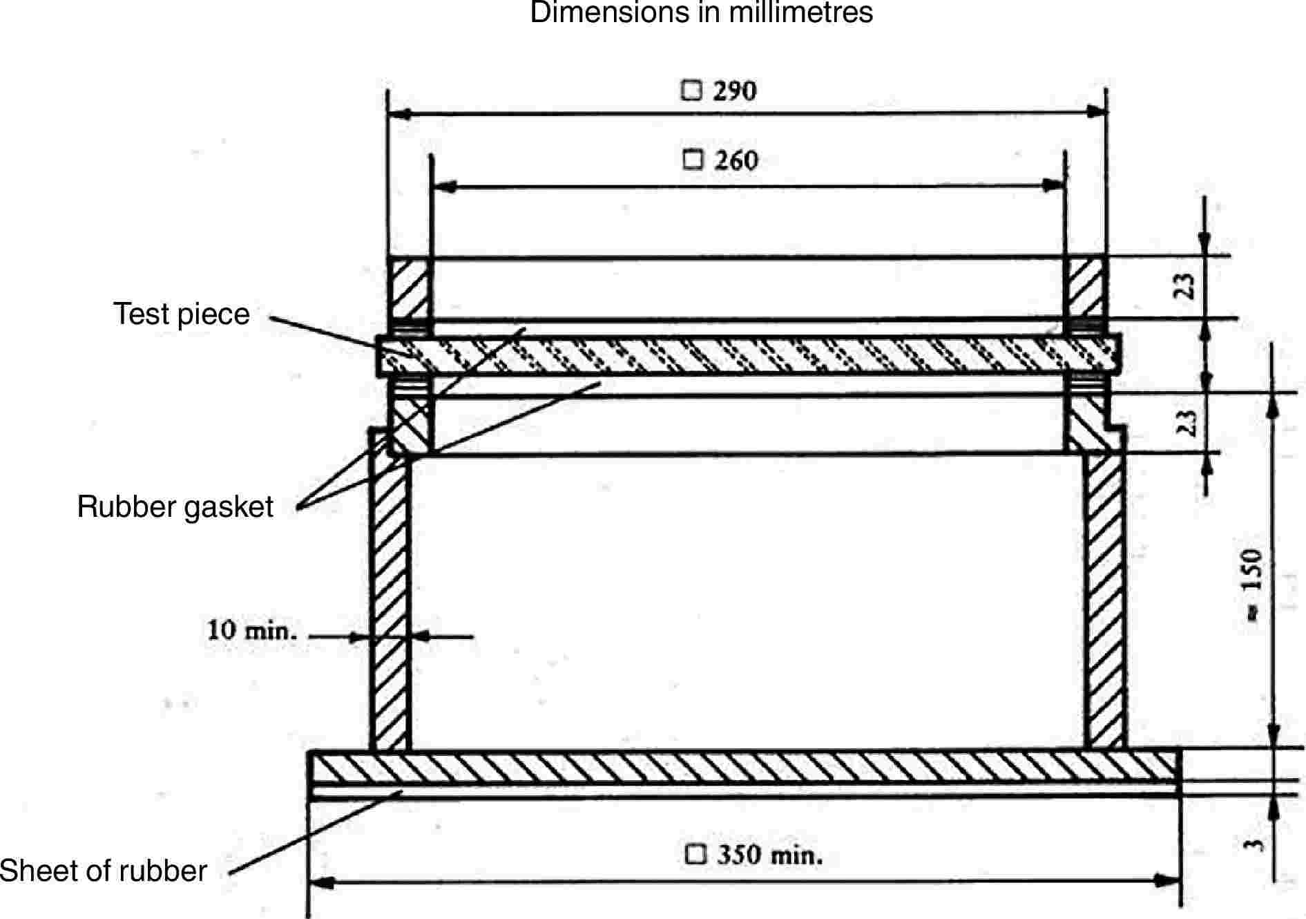
Figure 1 — Support for ball tests |
2.1.2. Test conditions
— Temperature: 20 ± 5 °C.
— Pressure: 860 to 1 060 mbar.
— Relative humidity: 60 ± 20 %.
2.1.3. Test piece
The test piece must be a flat square of side 300 + 10/– 0 mm.
2.1.4. Procedure
Condition the test piece at the specified temperature for at least four hours immediately preceding the test.
Place the test piece in the fixture (2.1.1.3). The plane of the test piece must be perpendicular, within 3°, to the incident direction of the ball.
The point of impact must be within 25 mm of the geometric centre of the test piece for a drop height of 6 m or less, and within 50 mm of the centre of the test piece for a drop height greater than 6 m. The ball must strike that face of the test piece which represents the outside face of the safety-glass pane when mounted on the vehicle. The ball is allowed to make only one impact.
2.2. 2 260-g-ball test
2.2.1. Apparatus
|
2.2.1.1. |
Hardened-steel ball with a mass of 2 260 ± 20 g and a diameter of approximately 82 mm. |
|
2.2.1.2. |
Device for dropping the ball freely from a height to be specified, or a device for giving the ball a velocity equivalent to that obtained by the free fall. When a device to project the ball is used, the tolerance on velocity must be ± 1 % of the velocity equivalent to that obtained by the free fall. |
|
2.2.1.3. |
The supporting fixture is as shown in Figure 1 and identical with that described in point 2.1.1.3. |
2.2.2. Test conditions
— Temperature: 20 ± 5 °C.
— Pressure: 860 to 1 060 mbar.
— Relative humidity: 60 ± 20 %.
2.2.3. Test piece
The test piece must be a flat square of side 300 + 10/– 0 mm or cut out from the flattest part of a windscreen or other curved pane of safety glass.
Alternatively, the whole windscreen or other curved pane of safety glass may be tested. In this case care must be taken to ensure adequate contact between the safety-glass pane and the support.
2.2.4. Procedure
Condition the test piece at the specified temperature for at least four hours immediately preceding the test.
Place the test piece in the fixture (2.1.1.3). The plane of the test piece must be perpendicular, within 3°, to the incident direction of the ball.
In the case of glass-plastic glazing the test piece is clamped to the support.
The point of impact must be within 25 mm of the geometric centre of the test piece. The ball must strike that face of the test piece which represents the inward face of the safety-glass pane when the latter is mounted on the vehicle. The ball is allowed to make only one impact.
3. HEADFORM TEST
3.1. Apparatus
|
3.1.1. |
Headform weight with a spherical or semi-spherical headform made of laminated hardwood covered with replaceable felt and with or without a cross-beam made of wood. There is a neck-shaped intermediate piece between the spherical part and the cross-beam and a mounting rod on the other side of the cross-beam. The dimensions are in accordance with Figure 2. The total mass of the apparatus is 10 ± 0,2 kg. 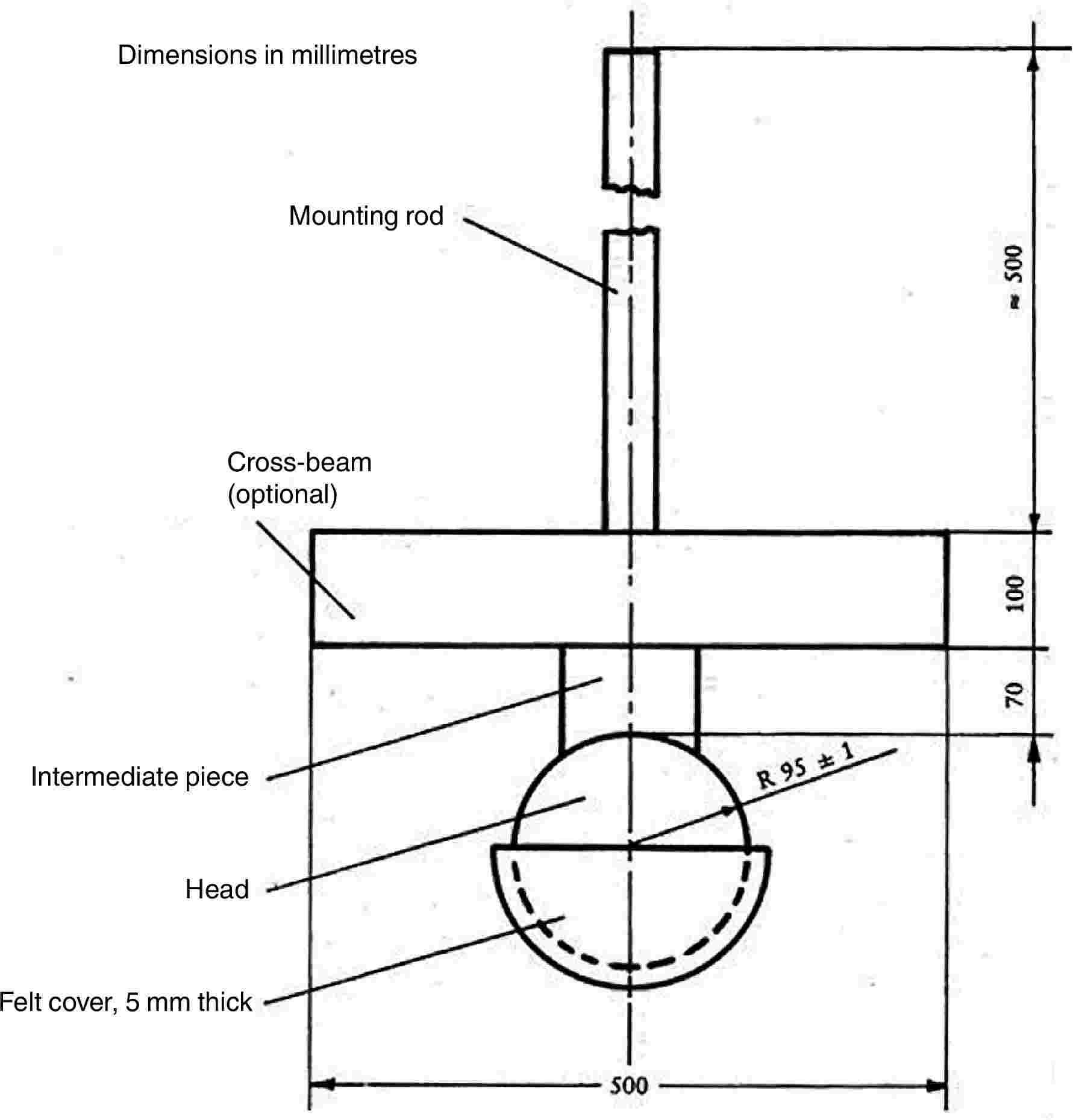
Figure 2 — Headform weight |
|
3.1.2. |
Device for dropping the headform weight freely from a height to be specified, or device for giving the weight a velocity equivalent to that obtained by the free fall. When a device to project the headform weight is used, the tolerance on velocity must be ± 1 % of the velocity equivalent to that obtained by the free fall. |
|
3.1.3. |
Supporting fixture, as shown in Figure 3, for testing flat test pieces. The fixture is composed of two steel frames, with machined borders 50 mm wide, fitting one over the other and faced with rubber gaskets about 3 mm thick and 15 ± 1 mm wide and a hardness 70 IRHD. The upper frame is held pressed against the lower frame by at least eight bolts. |
3.2. Test conditions
|
3.2.1. |
Temperature: 20 ± 5 °C. |
|
3.2.2. |
Pressure: 860 to 1 060 mbar. |
|
3.2.3. |
Relative humidity: 60 ± 20 %. 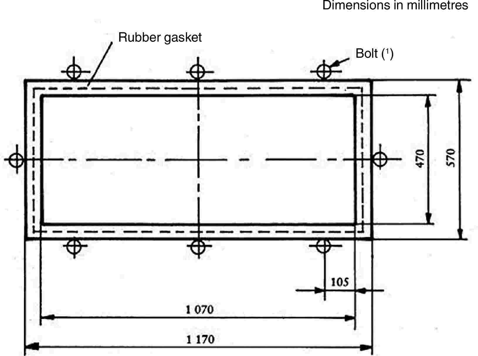
Figure 3 — Support for headform tests (1) The minimum recommended torque for M 20 is 30 Nm. |
3.3. Procedure
3.3.1. Test on a flat test piece
The flat test piece, having a length of 1 100 + 5/– 2 mm and a width of 500 + 5/– 2 mm is kept at a constant temperature of 20 ± 5 °C for at least four hours immediately preceding the test. Fix the test piece in the supporting frames (3.1.3); tighten the bolts so as to ensure that the movement of the test piece during the test does not exceed 2 mm. The plane of the test piece must be substantially perpendicular to the incident direction of the weight. The weight must strike the test piece within 40 mm of its geometric centre on that face which represents the inward face of the safety-glass pane when the latter is mounted on the vehicle, and be allowed to make only one impact.
The impact surface of the felt cover is to be replaced after 12 tests.
|
3.3.2. |
Tests on a complete windscreen (used only for a drop height of less than or equal to 1,5 m) Place the windscreen freely on a support with an interposed strip of rubber of hardness 70 IRHD and thickness about 3 mm, the width of contact over the whole perimeter being about 15 mm. The support consists of a rigid piece corresponding to the shape of the windscreen so that the headform weight strikes the internal surface. If necessary, the windscreen is clamped to the support by appropriate means. The support must rest on a rigid stand with an interposed sheet of rubber of hardness 70 IRHD and thickness about 3 mm. The surface of the windscreen must be substantially perpendicular to the incident direction of the headform weight. The headform weight must strike the windscreen at a point within 40 mm of its geometric centre on that face which represents the inward face of the safety glass pane when the latter is mounted on the vehicle, and be allowed to make only one impact. The impact surface of the felt cover is to be replaced after 12 tests. |
4. ABRASION TEST
4.1. Apparatus
|
4.1.1. |
Abrading instrument ( 26 ), shown diagrammatically in Figure 4 and consisting of: — a horizontal turntable, with centre clamp, which revolves counter-clockwise at 65 to 75 rev/min, and —
Figure 4 — Diagram of abrading instrument — two weighted parallel arms each carrying a special abrasive wheel freely relating on a ball-bearing horizontal spindle; each wheel rests on the test specimen under the pressure exerted by a mass of 500 g. The turntable of the abrading instrument must rotate regularly, substantially in one plane (the deviation from this plane must not be greater than ± 0,05 mm at a distance of 1,6 mm from turntable periphery). The wheels must be mounted in such a way that when they are in contact with the rotating test piece they rotate in opposite directions so as to exert, twice during each rotation of the test piece, a compressive and abrasive action along curved lines over an annular area of about 30 cm2. |
|
4.1.2. |
Abrasive wheels ( 27 ), each 45 to 50 mm in diameter and 12,5 mm thick, composed of a special finely screened abrasive embedded in a medium-hard rubber. The wheels must have a hardness of 72 ± 5 IRHD, as measured at four points equally spaced on the centre line of the abrading surface, the pressure being applied vertically along a diameter of the wheel and the readings being taken 10 seconds after full application of the pressure. The abrasive wheels must be prepared for use by very slow rotation against a sheet of flat glass to ensure that their surface is completely even. |
|
4.1.3. |
Light source consisting of an incandescent lamp with its filament contained within a parallelepiped measuring 1,5 mm × 1,5 mm × 3 mm. The voltage at the lamp filament must be such that the colour temperature is 2 856 K ± 50 K. The voltage must be stabilised within ± 1/1 000. The instrument used to check the voltage must be of appropriate accuracy. |
|
4.1.4. |
Optical system consisting of a lens with a focal length, ƒ, of at least 500 mm and corrected for chromatic aberrations. The full aperture of the lens must not exceed ƒ/20. The distance between the lens and the light source is adjusted in order to obtain a light beam which is substantially parallel. A diaphragm is inserted to limit the diameter of the light beam to 7 mm ± 1 mm. This diaphragm must be situated at a distance of 100 ± 50 mm from the lens on the side remote from the light source. |
|
4.1.5. |
Equipment for measuring scattered light (see Figure 5), consisting of a photoelectric cell with an integrating sphere 200 to 250 mm in diameter. The sphere is equipped with entrance and exit ports for the light. The entrance port must be circular and have a diameter at least twice that of the light beam. The exit port of the sphere is provided with either a light trap or a reflectance standard, according to the procedure as described in point 4.4.3 below. The light trap absorbs all the light when no test piece is inserted in the light beam. The axis of the light beam must pass through the centre of the entrance and exit ports. The diameter, b, of the light-exit port must be equal to 2a · tan 4°, where a is the diameter of the sphere. The photoelectric cell must be mounted in such a way that it cannot be reached by light coming directly from the entrance port or from the reflectance standard. The surfaces of the interior of the integrating sphere and the reflectance standard must be of substantially equal reflectance and matt and non-selective. The output of the photoelectric cell must be linear within ± 2 % over the range of luminous intensities used. The design of the instrument must be such that there is no galvanometer deflection when the sphere is dark. The whole apparatus must be checked at regular intervals by means of calibration standards of defined haze. If haze measurements are made using equipment or methods differing from those defined above, the results must be corrected, if necessary, to bring them into agreement with those obtained by the apparatus described above. 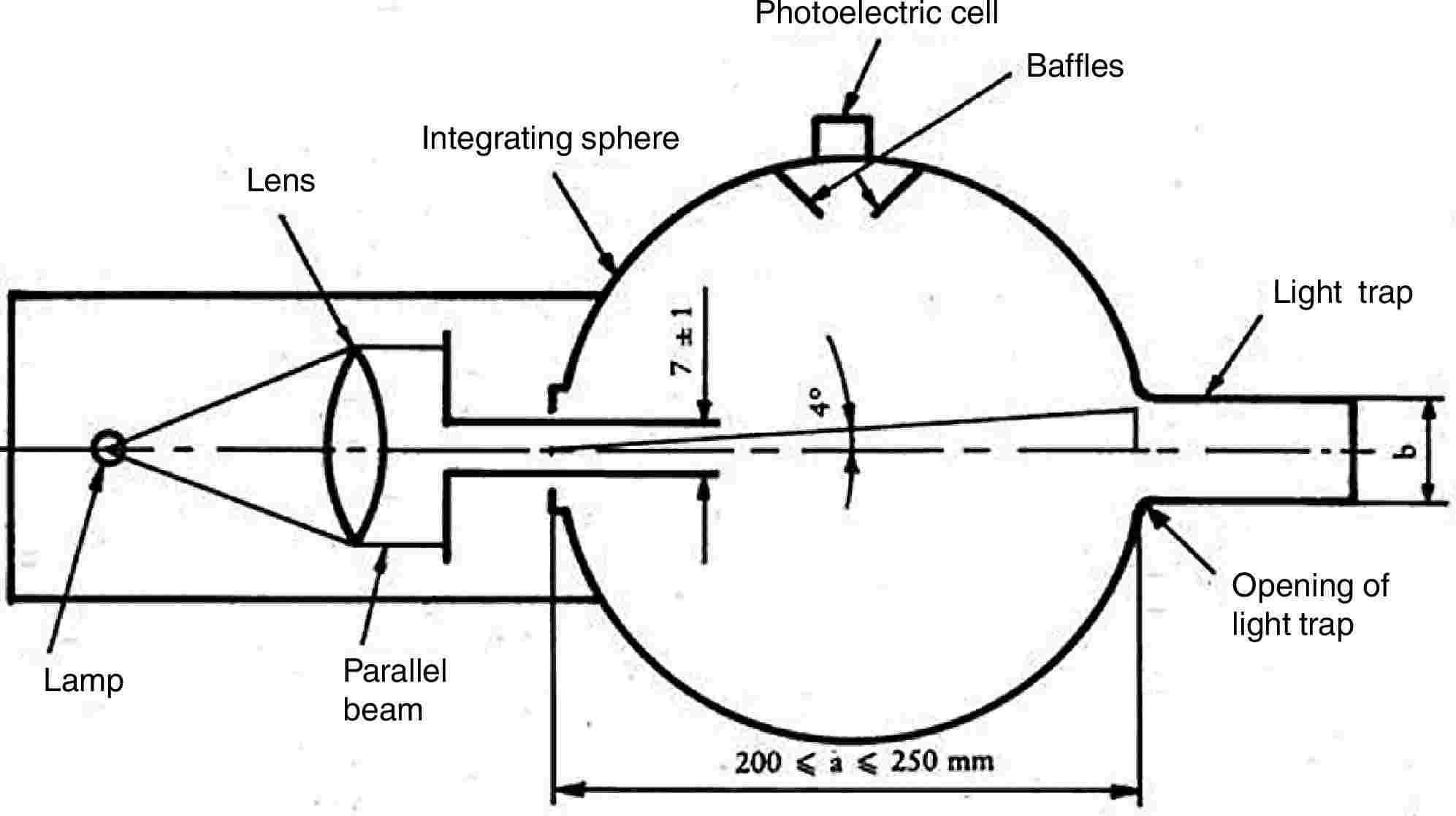
Figure 5 — Hazamenter |
4.2. Test conditions
|
4.2.1. |
Temperature: 20 ± 5 °C. |
|
4.2.2. |
Pressure: 860 to 1 060 mbar. |
|
4.2.3. |
Relative humidity: 60 ± 20 %. |
4.3. Test pieces
The test pieces must be flat squares whose sides measure 100 mm having both surfaces substantially plane and parallel and if necessary having a fixing hole 6,4 + 0,2/– 0 mm in diameter drilled in the centre.
4.4. Procedure
The abrasion test is carried out on that surface of the test piece which represents the outside face of the safety-glass pane when the latter is mounted on the vehicle and also on the inward face in the case of a glass pane with a plastic coating.
|
4.4.1. |
Immediately before and after the abrasion, clean the test pieces in the following manner: (a) wipe with a linen cloth under clean running water; (b) rinse with distilled or demineralised water; (c) blow dry with oxygen or nitrogen; (d) remove possible traces of water by dabbing softly with a damp linen cloth. If necessary, dry by pressing lightly between two linen cloths. Any treatment with ultrasonic equipment must be avoided. After cleaning, the test pieces must be handled only by their edges and stored to prevent damage to, or contamination of, their surfaces. |
|
4.4.2. |
Condition the test pieces for a minimum time of 48 hours at a temperature of 20 ± 5 °C and a relative humidity of 60 ± 20 %. |
|
4.4.3. |
Immediately place the test piece against the entrance port of the integrating sphere. The angle between the normal (perpendicular) to the surface of the test piece and the axis of the beam must not exceed 8°. Take four readings as indicated in the following table:
Repeat readings T1, T2, T3 and T4 with other specified positions of the test piece to determine uniformity. Calculate the total transmittance Tt = T2/T1. Calculate the diffuse transmittance Td as follows: Td = (T4 – T3(T2/T1))/T1 Calculate the percentage haze, or light, or both, scattered, as follows: (Td/Tt) × 100 % Measure the initial haze of the test piece at a minimum of four equally spaced points in the unabraded area in accordance with the formula above. Average the results for each test piece. In lieu of the four measurements, an average value may be obtained by rotating the piece uniformly at 3 rev/sec or more. For each safety-glass pane, carry out three tests with the same kind. Use the haze as a measure of the subsurface abrasion, after the test piece has been subjected to the abrasion test. Measure the light scattered by the abraded track at a minimum of four equally spaced points along the track in accordance with the formula above. Average the results for each test piece. In lieu of the four measurements, an average value may be obtained by rotating the piece uniformly at 3 rev/sec or more. |
|
4.5. |
The abrasion test is to be carried out only at the discretion of the laboratory conducting the test with due regard to the information already at its disposal. Except for glass-plastic materials, in the case of changes in the interlayer or material thickness, for example, further testing is normally not necessary. |
|
4.6. |
Indices of difficulty of the secondary characteristics No secondary characteristics are involved. |
5. HIGH-TEMPERATURE TEST
5.1. Procedure
Heat to 100 °C three test samples or three test pieces of at least 300 mm × 300 mm taken by the laboratory from three windscreens or three glass panes other than windscreens, as appropriate, one of whose dimensions corresponds to the upper edge of the pane.
Maintain this temperature for a period of two hours, then allow the test sample(s) to cool to room temperature. If the safety-glass pane has both external surfaces of inorganic material, the test may be carried out by immersing the test sample vertically in boiling water for the specified period of time, care being taken to avoid undue thermal shock. If specimens are cut from windscreens, one edge of each such test specimen shall be part of an edge of the windscreen.
5.2. Indices of difficulty of the secondary characteristics
|
Colourless |
Tinted |
|
|
Colouring of the interlayer: |
1 |
2 |
The other secondary characteristics are not involved.
5.3. Interpretation of results
|
5.3.1. |
The test for resistance to high temperature is considered to give a positive result if bubbles or other defects are not formed more than 15 mm from an uncut edge or 25 mm from a cut edge of the test piece or sample or more than 10 mm from any cracks which may occur during the test. |
|
5.3.2. |
A set of test pieces or samples submitted for component type-approval are considered satisfactory from the point of view of the high-temperature resistance test if either of the following conditions is fulfilled:
|
6. RESISTANCE-TO-RADIATION TEST
6.1. Test method
6.1.1. Apparatus
|
6.1.1.1. |
Radiation source consisting of a medium-pressure mercury-vapour arc lamp with a tubular quartz bulb of ozone-free type; the bulb axis is vertical. The nominal dimensions of the lamp are 360 mm in length by 9,5 mm in diameter. The arc length is 300 ± 4 mm. The lamp must be operated at 750 ± 50 W. Any other source of radiation which produces the same effects as the lamp specified above may be used. To check that the effects of another source are the same, a comparison is made by measuring the amount of energy emitted within a wavelength range of 300 to 450 nm, all other wavelengths being removed by the use of suitable filters. The alternative source is then used with these filters. In the case of safety-glass panes for which there is no satisfactory correlation between this test and the conditions of use it will be necessary to review the test conditions. |
|
6.1.1.2. |
Power supply transformer and capacitor capable of supplying to the lamp (6.1.1.1) a starting peak-voltage of 1 100 V minimum and an operating voltage of 500 ± 50 V. |
|
6.1.1.3. |
Device for mounting and rotating the test specimens at 1 to 5 rev/min about the centrally located radiation source in order to ensure even exposure. |
6.1.2. Test pieces
|
6.1.2.1. |
The size of the test pieces is 76 mm × 300 mm. |
|
6.1.2.2. |
The test pieces are cut by the laboratory from the upper part of the panes in such a way that: — in the case of glass panes other than windscreens the upper edge of the test pieces coincides with the upper edge of the panes, — in the case of windscreens the upper edge of the test pieces coincides with the upper limit of the zone in which regular transmittance is to be checked and determined in accordance with point 9.1.2.2 of this Annex. |
6.1.3. Procedure
Check the regular light transmittance, determined in accordance with points 9.1.1 to 9.1.2 of this Annex, of three test samples before exposure. Protect a portion of each sample from the radiation, and then place the sample in the test apparatus 230 mm from and parallel lengthwise to the lamp axis. Maintain the temperature of the samples at 45 ± 5 °C throughout the test. That face of each test sample which would constitute a grazed exterior part of the tractor must face the lamp. For the type of lamp specified in point 6.1.1.1 the exposure time is 100 hours.
After exposure, measure the regular light transmittance again in the exposed area of each sample.
|
6.1.4. |
Each test piece or sample (three in total) is subjected, in accordance with the procedure above, to radiation such that the radiation on each point of the test piece or sample produces on the interlayer used the same effect as that which would be produced by solar radiation of 1 400 W/m2 for 100 hours. |
6.2. Indices of difficulty of the secondary characteristics
|
Colourless |
Tinted |
|
|
Colouring of glass |
2 |
1 |
|
Colouring of interlayer |
1 |
2 |
The other secondary characteristics are not involved.
6.3. Interpretation of results
|
6.3.1. |
The test for resistance to radiation is deemed to have given a positive result if the following conditions are fulfilled:
|
|
6.3.2. |
A set of test pieces or samples submitted for component type-approval is considered satisfactory from the point of view of the resistance to radiation test if one of the following conditions is fulfilled:
|
7. RESISTANCE-TO-HUMIDITY TEST
7.1. Procedure
Keep three test samples or three test pieces at least 300 mm × 300 mm square vertically for two weeks in a closed container in which the temperature is maintained at 50 ± 2 °C and the relative humidity at 95 % ± 4 % ( 28 ).
Test pieces are prepared in such a way that:
— one edge of each test piece is part of an original edge of the windscreen,
— should several test pieces be tested at the same time, adequate spacing must be provided between them.
Precautions must be taken to prevent condensation from the walls or ceiling of the test chamber from falling on the test specimens.
7.2. Indices of difficulty of the secondary characteristics
|
Colourless |
Tinted |
|
|
Colouring of interlayer |
1 |
2 |
The other secondary characteristics are not involved.
7.3. Interpretation of results
|
7.3.1. |
Safety-glass panes are deemed to be satisfactory from the point of view of resistance to humidity if no significant change is observed more than 10 mm from the uncut edges or more than 15 mm from the cut edges, following a stay of two hours in the ambient atmosphere by ordinary and treated laminated glass, and of 48 hours in the ambient atmosphere by plastic-coated glass panes and plastic glazing. |
|
7.3.2. |
A set of test pieces or samples submitted for component type-approval is considered satisfactory from the point of view of the resistance to humidity test if one of the following conditions is fulfilled:
|
8. TESTING OF RESISTANCE TO CHANGES IN TEMPERATURE
8.1. Test method
Two 300 × 300 mm test pieces are placed in an enclosed chamber for six hours at a temperature of – 40 ± 5 °C; they are then placed in the ambient air at a temperature of 23 ±°C for an hour, or until the test piece has reached a stable temperature. They are then placed in an air flow at a temperature of 72 ± 2 °C for three hours. The test pieces are then examined after they have been returned to the ambient air at 23 ± 2 °C and cooled to that temperature.
8.2. Index of difficulty of the secondary characteristics
|
Colourless |
Tinted |
|
|
Colouring of plastic interlayer or coating |
1 |
2 |
No other secondary characteristics are involved.
8.3. Interpretation of results
The test of resistance to changes in temperature is considered to have given a positive result if the test pieces display no cracking, opacification, exfoliation or other obvious deterioration.
9. OPTICAL QUALITIES
9.1. Light transmission test
9.1.1. Apparatus
|
9.1.1.1. |
Light source consisting of an incandescent lamp having its filament contained within a parallelepiped measuring 1,5 mm × 1,5 mm × 3 mm. The voltage at the lamp filament must be such that the colour temperature is 2 856 K ± 50 K. This voltage is stabilised within ± 1/1 000. The instrument used to check the voltage must be of appropriate accuracy. |
|
9.1.1.2. |
Optical system consisting of a lens with a focal length of at least 500 mm and corrected for chromatic aberrations. The full aperture of the lens must not exceed f/20. The distance between the lens and the light source must be so adjusted as to obtain a light beam which is substantially parallel. A diaphragm is inserted to limit the diameter of the light beam to 7 ± 1 mm. This diaphragm is situated at a distance of 100 ± 50 mm from the lens on the side remote from the light source. The point of measurement is taken at the centre of the light beam. |
|
9.1.1.3. |
Measuring equipment. The receiver must have a relative spectral sensitivity in substantial agreement with the relative spectral luminous efficiency for the CIE (Commission Internationale de L'Éclairage) standard photometric observer for photoptic vision. The sensitive surface of the receiver is covered with a diffusing medium and must have at least twice the cross-section of the light beam emitted by the optical system. If an integrating sphere is used, the aperture of the sphere must have a cross-sectional area at least twice that of the parallel portion of the beam. The linearity of the receiver and the associated indicated instrument must be better than 2 % of the effective part of the scale. The receiver must be situated at the axis of the light beam. |
9.1.2. Procedure
So adjust the instrument indicating the response of the receiver that it indicates 100 divisions when the safety-glass pane is not inserted in the light path. When no light is falling on the receiver, the instrument must read zero.
Place the safety-glass pane at a distance from the receiver equal to approximately five times the diameter of the receiver. Insert the safety-glass pane between the diaphragm and the receiver and adjust its orientation in such a way that the angle of incidence of the light beam is equal to 0° ± 5°. The regular transmittance is measured on the safety-glass pane, and for every point measured the number of divisions, n, shown on the indicating instrument, is read. The regular transmittance τr is equal to n/100.
|
9.1.2.1. |
In the case of windscreens, alternative test methods may be applied using either a test sample cut from the flattest part of a windscreen or a specially prepared flat square with material and thickness characteristics identical to those of the actual windscreen, the measurements being taken normal (perpendicular) to the glass pane. |
|
9.1.2.2. |
The test is carried out in the zone I specified in point 9.2.5.2 of this Annex. |
|
9.1.2.3. |
In the case of tractors for which it is not possible to determine zone I as defined in point 9.2.5.2, the test is carried out in zone I′ as defined in point 9.2.5.3 of this Annex. |
9.1.3. Indices of difficulty of the secondary characteristics
|
Colourless |
Tinted |
|
|
Colouring of the glass |
1 |
2 |
|
Colouring of the interlayer (in the case of laminated windscreens) |
1 |
2 |
|
not included |
included |
|
|
Shade and/or obscuration bands |
1 |
2 |
The other secondary characteristics are not involved.
9.1.4. Interpretation of results
|
9.1.4.1. |
The regular transmittance measured according to point 9.1.2 in the case of windscreens must not be less than 75 %, and in the case of windows other than windscreens not less than 70 %. |
|
9.1.4.2. |
In the case of windows situated at points which are not essential to the driver's field of vision (glazed roof, for example) the regular transmittance factor of the light from the pane may be less than 70 %. Windows having a regular light transmittance factor of less than 70 % must be marked with an appropriate symbol. |
9.2. Optical-distortion test
9.2.1. Scope
The method specified is a projection method which permits evaluation of the optical distortion of a safety-glass pane.
9.2.1.1. Definitions
|
9.2.1.1.1. |
Optical deviation: the angle between the true and the apparent direction of a point viewed through the safety-glass pane, the magnitude of the angle being a function of the angle of incidence of the line of sight, the thickness and inclination of the glass pane, and the radius of curvature at the point of incidence. |
|
9.2.1.1.2. |
Optical distortion in a direction MM′: the algebraic difference in angular deviation Δα measured between two points M and M′ on the surface of the safety-glass pane, the distance between the two points being such that their projections in a plane at right angles to the direction of vision are separated by a given distance Δx (see Figure 6). Anti-clockwise deviation is to be regarded as positive and clockwise deviation as negative. |
|
9.2.1.1.3. |
Optical distortion at a point M: the optical distortion maximum for all directions MM′ from the point M. |
9.2.1.2. Apparatus
This method entails the projection of an appropriate slide (raster) on to the display screen through the safety-glass pane being tested. The change caused in the shape of the projected image by the insertion of the safety-glass pane in the line of light provides a measure of the distortion. The apparatus comprises the following items, arranged as shown in Figure 9.
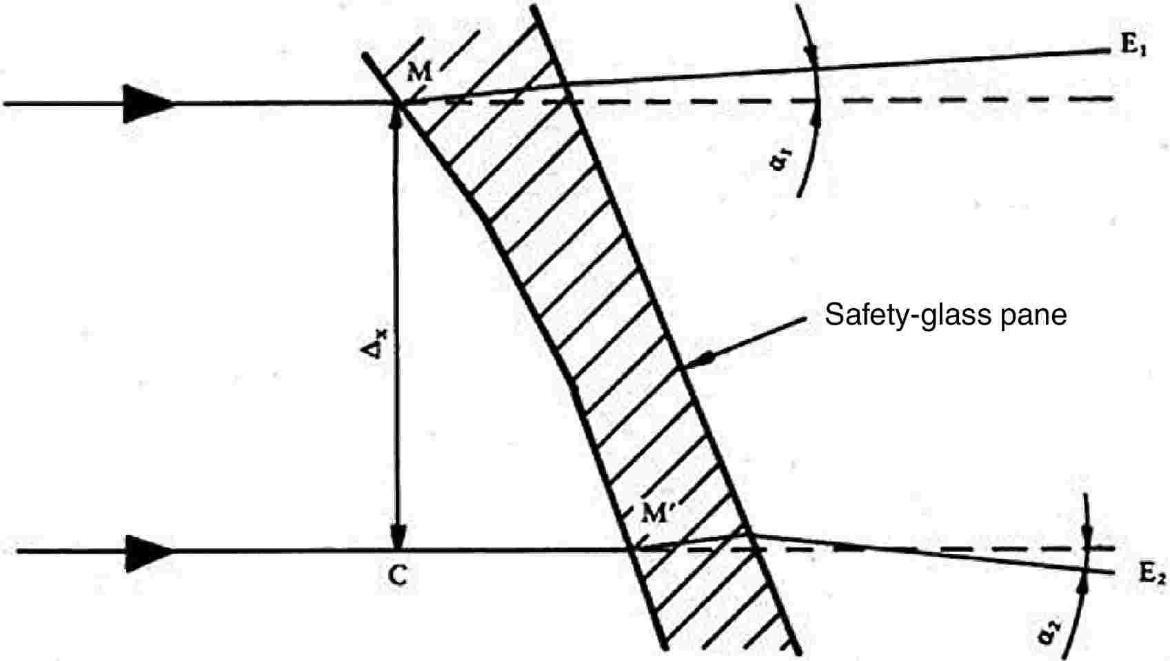
Figure 6 — Diagrammatic representation of optical distortion
|
Notes: |
Δα = α1 – α2, |
i.e. the optical distortion in the direction MM′. |
|
Δx = MC |
i.e. the distance between two straight lines parallel to the direction of vision and passing through the points M and M′. |
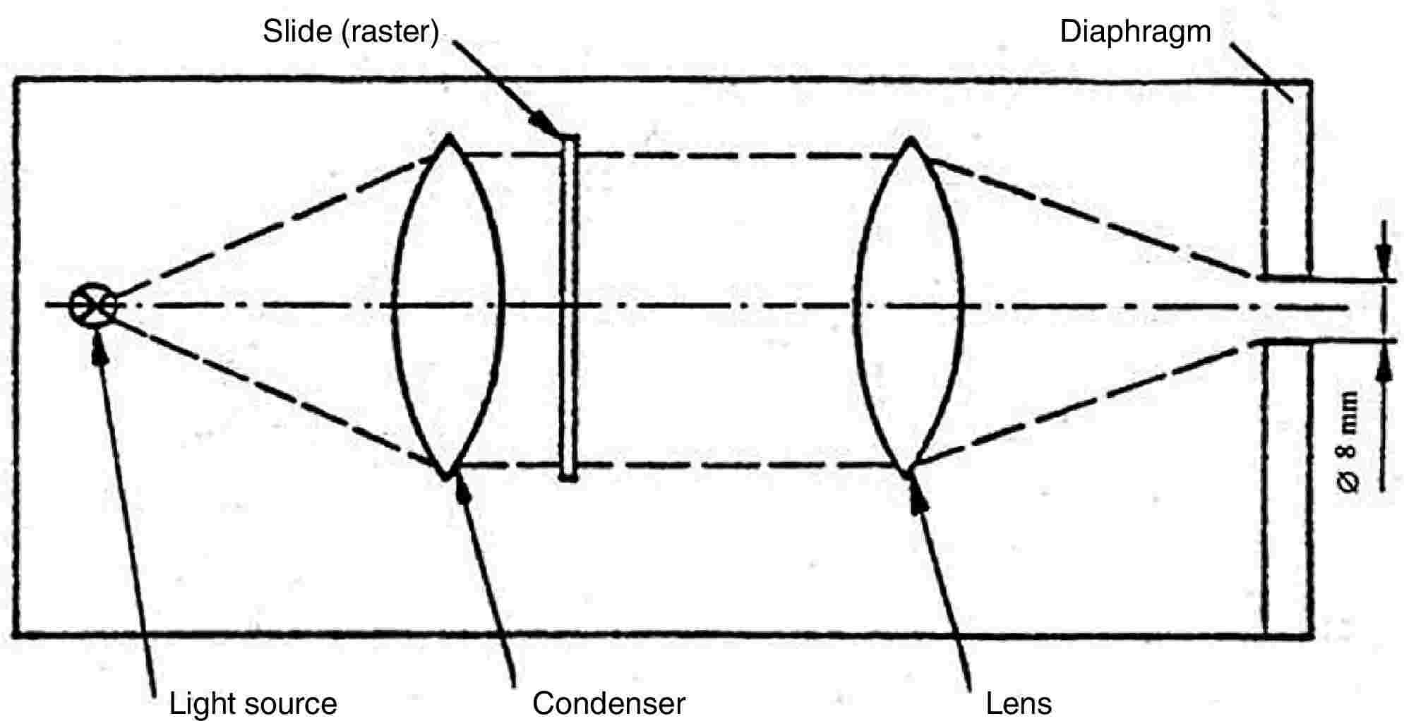
Figure 7 — Optical arrangement of the projector
|
9.2.1.2.1. |
Projector, of good quality, with a high-intensity point light source, having for example the following characteristics: — focal length at least 90 mm, — aperture approximately 1/2,5, — 150 W quartz halogen lamp (if used without a filter), — 250 W quartz halogen lamp (if a green filter is used). 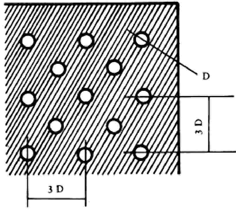
Figure 8 — Enlarged section of the slide The projector is shown schematically in Figure 7. A diaphragm of 8 mm diameter is positioned approximately 10 mm from the front lens. |
|
9.2.1.2.2. |
Slides (rasters) consisting, for example, of an array of bright circular shapes on a dark background (see Figure 8). The slide must be of sufficiently high quality and contrast to enable measurement to be carried out with an error of less than 5 %. In the absence of the safety-glass pane to be examined, the dimensions of the circular shapes must be such that when the circular shapes are projected they form an array of circles of diameter ((R1 + R2)/R1) Δx where Δx = 4 mm (see Figures 6 and 9). 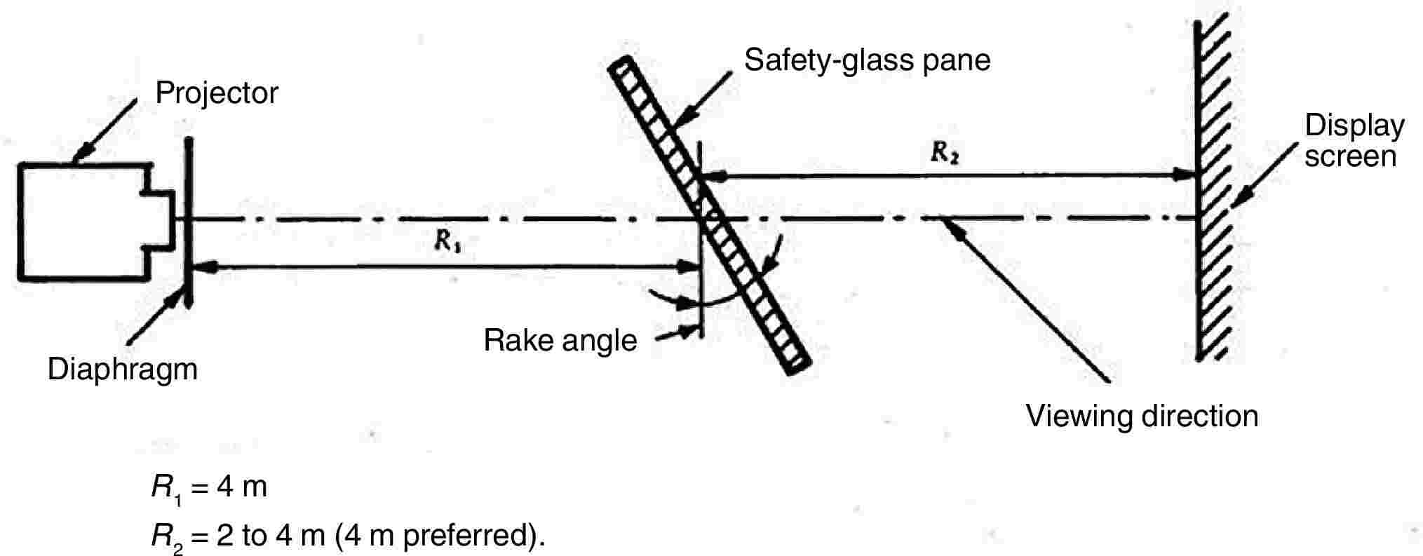
Figure 9 — Arrangement of the apparatus for the optical-distortion test |
|
9.2.1.2.3. |
Support stand, preferably one permitting vertical and horizontal scanning, as well as rotation of the safety-glass pane. |
|
9.2.1.2.4. |
Checking template, for measuring changes in dimensions where a rapid assessment is required. A suitable design is shown in Figure 10. 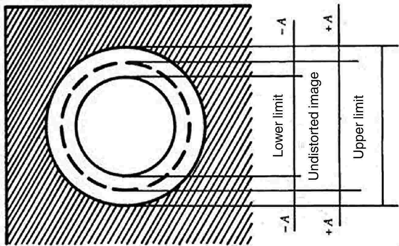
Figure 10 — Design for a suitable checking template |
9.2.1.3. Procedure
9.2.1.3.1. General
Mount the safety-glass pane on the support stand (9.2.1.2.3) at the designated rake angle. Project the test image through the area being examined. Rotate the safety-glass pane or move it either horizontally or vertically in order to examine the whole of the specified area.
9.2.1.3.2. Assessment using a checking template
Where a rapid assessment with a possible margin of error of up to 20 % is sufficient, calculate the value of A (see Figure 10) from the limit value ΔαL for the change in deviation and the value of R 2, the distance from the safety-glass pane to the display screen:
A = 0,145 ΔαL· R2
The relationship between the change in diameter of the projected image Δd and the change in angular deviation Δα is given by:
Δd = 0,29 Δα · R2
where:
|
Δd |
is expressed in millimetres, |
|
A |
is expressed in millimetres, |
|
ΔαL |
is expressed in minutes of arc, |
|
Δα |
is expressed in minutes of arc, and |
|
R2 |
is expressed in metres. |
9.2.1.3.3. Measurement using a photoelectric device
Where a precise measurement with a possible margin of error of less than 10 % of the limit value is required, measure Δd on the projection axis, the value of the spot width being taken at the point where the luminance is 0,5 times the maximum spot luminance value.
9.2.1.4. Expression of results
Evaluate the optical distortion of the safety-glass panes by measuring Δd at any point of the surface and in all directions in order to find Δd max.
9.2.1.5. Alternative method
In addition, a strioscopic technique is permitted as an alternative to the projection techniques, provided that the accuracy of the measurements given in points 9.2.1.3.2 and 9.2.1.3.3 is maintained.
|
9.2.1.6. |
The distance Δx must be 4 mm. |
|
9.2.1.7. |
The windscreen must be mounted at the same rake angle as on the tractor. |
|
9.2.1.8. |
The projection axis in the horizontal plane must be maintained approximately normal to the trace of the windscreen in that plane. |
|
9.2.2. |
The measurements are performed in zone I as defined in point 9.2.5.2 of this Annex.
|
|
9.2.3. |
Indices of difficulty of the secondary characteristics 9.2.3.1. Nature of the material
9.2.3.2. Other secondary characteristics No other secondary characteristics are involved. |
|
9.2.4. |
Number of samples Four samples must be submitted for testing. |
|
9.2.5. |
Definition of the zone of vision of tractor windscreens
|
|
9.2.6. |
Interpretation of results A type of windscreen is considered satisfactory as regards optical distortion if, in the four samples submitted for testing, optical distortion does not exceed a maximum value of 2′ of an arc in either zone I or zone I′.
|
9.3. Secondary-image separation test
9.3.1. Scope
Two test methods are recognised:
— target test, and
— collimation telescope test.
These test methods may be used for component type-approval, quality-control or product-evaluation purposes, as appropriate.
9.3.1.1. Target test
9.3.1.1.1. Apparatus
This method involves viewing an illuminated target through the safety-glass pane. The target may be designed in such a way that the test can be carried out on a simple go/no go basis.
The target must preferably be of one of the following types:
(a) an illuminated ring target whose outer diameter, D, subtends an angle of η minutes of arc at a point situated at x metres (Figure 11a); or
(b) an illuminated ring and spot target whose dimensions are such that the distance, D, from a point on the edge of the spot to the nearest point on the inside of the circle subtends an angle of η minutes of arc at a point situated at x metres (Figure 11b);
where:
|
η |
is the limit value of secondary-image separation, |
|
x |
is the distance from the safety-glass pane to the target (not less than 7 m), |
|
D |
is given by the formula: |
D = x · tan η
The illuminated target consists of a light box, approximately 300 mm × 300 mm × 150 mm, whose front is most conveniently constructed of glass masked with opaque black paper or coated with matt black paint. The box is illuminated by a suitable light source. The inside of the box is coated with matt white paint. It may be convenient to use other forms of target, such as that shown in Figure 14. It is also acceptable to replace the target system by a projection system and to view the resulting images on a screen.
9.3.1.1.2. Procedure
Mount the safety-glass pane at the specified rake angle on a suitable stand in such a way that the observation is carried out in the horizontal plane passing through the centre of the target.
The light box must be viewed, in a dark or semi-dark room, through each part of the area being examined, in order to detect the presence of any secondary image associated with the illuminated target. Rotate the safety-glass pane as necessary to ensure that the correct direction of view is maintained. A monocular may be used for viewing.
9.3.1.1.3. Expression of results
Determine whether:
— when target (a) (see Figure 11a) is used, the primary and secondary image of the circle separate, i.e. whether the limit value of η is exceeded, or
— when target (b) (see Figure 11b) is used, the secondary image of the spot shifts beyond the point of tangency with the inside edge of the circle, i.e. whether the limit value of η is exceeded.
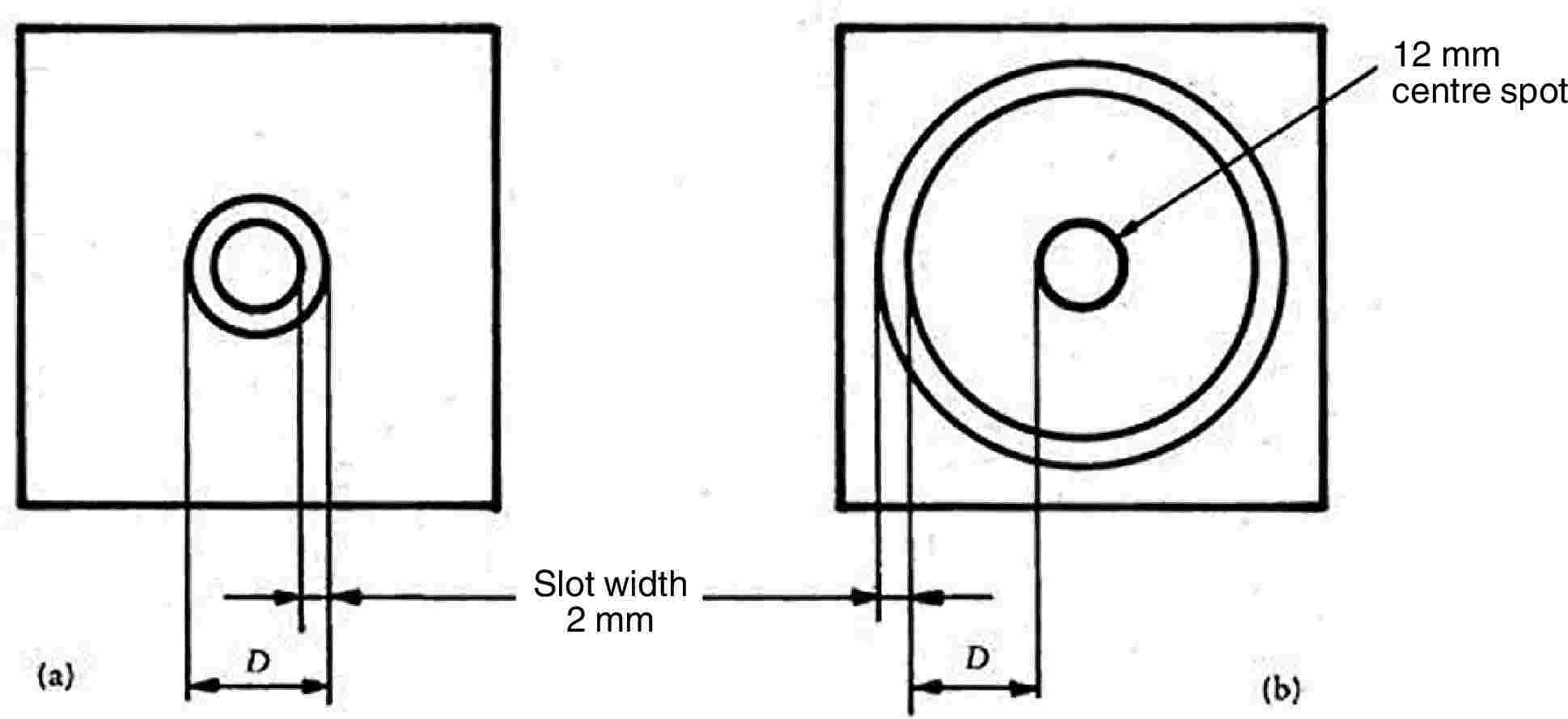
Figure 11 — Dimensions of targets
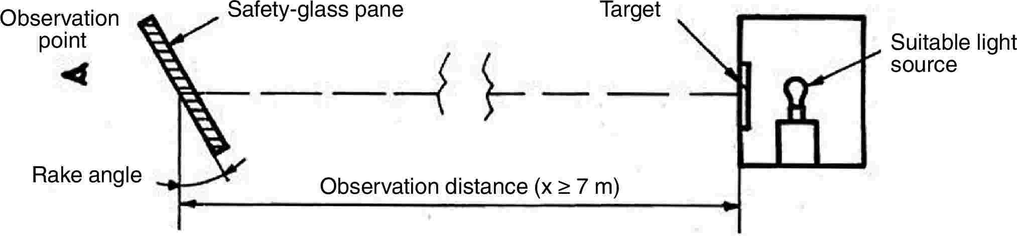
Figure 12 — Arrangement of apparatus
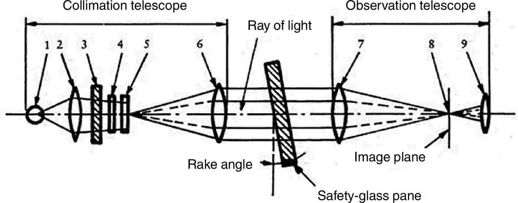
|
1. |
Lamp bulb. |
|
2. |
Condenser aperture > 8,6 mm. |
|
3. |
Ground-glass screen aperture > condenser aperture. |
|
4. |
Colour filter with central hole approximately 0,3 mm in diameter; diameter > 8,6 mm. |
|
5. |
Polar-coordinate plate, diameter > 8,6 mm. |
|
6. |
Achromatic lens, f ≥ 86 mm, aperture 10 mm. |
|
7. |
Achromatic lens, f ≥ 86 mm, aperture 10 mm. |
|
8. |
Black spot, diameter approximately 0,3 mm. |
|
9. |
Achromatic lens, f = 20 mm, aperture ≤ 10 mm. |
Figure 13 — Apparatus for collimation telescope test
9.3.1.2. Collimation telescope test
If necessary, the procedure described in this point is applied.
9.3.1.2.1. Apparatus
The apparatus comprises a collimator and a telescope and may be set up in accordance with Figure 13. However, any equivalent optical system may be used.
9.3.1.2.2. Procedure
The collimation telescope forms at infinity the image of a polar-coordinate system with a bright point at its centre (see Figure 14). In the focal plane of the observation telescope, a small opaque spot with a diameter slightly larger than that of the projected bright point is placed on the optical axis, thus obscuring the bright point.
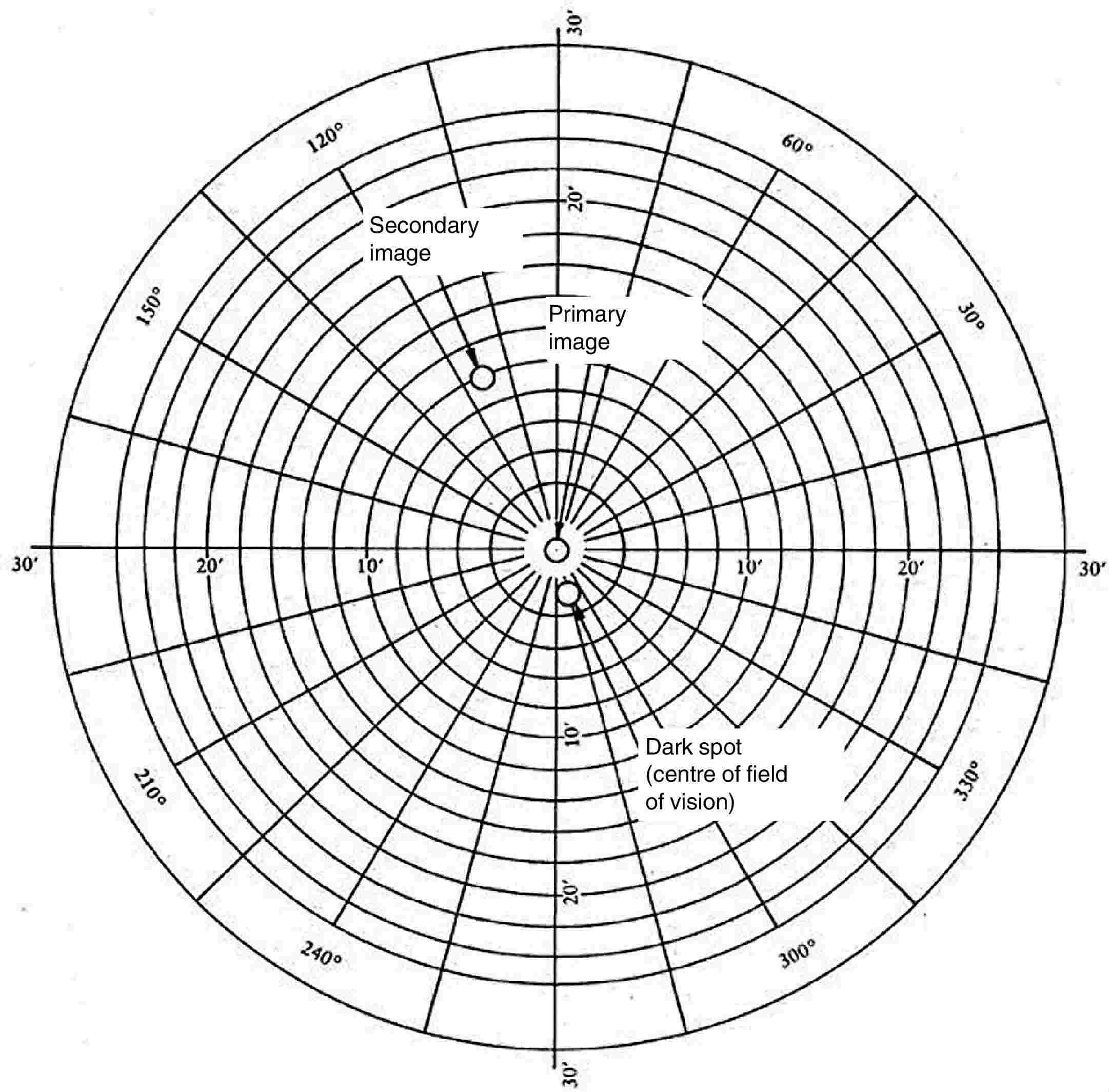
Figure 14 — Example of observation by the collimation telescope test method
When a test piece which exhibits a secondary image is placed between the telescope and the collimator, a second, less bright point appears at a certain distance from the centre of the polar-coordinate system. The secondary-image separation can be read out as the distance between the points seen through the observation telescope (see Figure 14). (The distance between the dark spot and the bright point at the centre of the polar-coordinate system represents the optical deviation.)
9.3.1.2.3. Expression of results
The safety-glass pane is first examined by a simple scanning technique to establish the area giving the strongest secondary image. That area is then examined by the collimator telescope system at the appropriate angle of incidence. The maximum secondary-image separation is measured.
|
9.3.1.3. |
The direction of observation in the horizontal plane must be maintained approximately normal to the trace of the windscreen in that plane. |
|
9.3.2. |
The measurements are performed according to tractor category in the zones defined in point 9.2.2. 9.3.2.1. Tractor type The test must be repeated if the windscreen is to be mounted on a tractor of a type which has a forward field of vision different from that of the tractor for which the windscreen has already been approved. |
|
9.3.3. |
Indices of difficulty of the secondary characteristics 9.3.3.1. Nature of the material
9.3.3.2. Other secondary characteristics No other secondary characteristics are involved. |
|
9.3.4. |
Number of samples Four samples must be submitted for testing. |
|
9.3.5. |
Interpretation of results A type of windscreen is considered satisfactory as regards secondary-image separation if, in the four samples submitted for testing, separation of the primary and secondary image does not exceed a maximum value of 15′ of an arc.
|
9.4. Identification of colours test
When a windscreen is tinted in the zones defined in point 9.2.5.2 or point 9.2.5.3, four windscreens are tested for identifiability of the following colours:
— white,
— selective yellow,
— red,
— green,
— blue,
— amber.
10. FIRE-RESISTANCE TEST
10.1. Purpose and scope of application
This method enables the horizontal burning rate of materials used in the occupant compartment of tractors after exposure to a small flame to be determined. This method permits testing of materials and components of a tractor's interior equipment individually or in combination up to a thickness of 15 mm. It is used to judge the uniformity of production lots of such materials with respect to their burning behaviour. Because of the many differences between the real-world situation (application and orientation within a tractor; conditions of use; ignition source, etc.) and the precise test conditions prescribed herein, this method cannot be considered as suitable for evaluation of all true in-tractor burning characteristics.
10.2. Definitions
|
10.2.1. |
Burning rate: the quotient of the burnt distance measured according to this method and the time taken to burn that distance. It is expressed in millimetres per minute. |
|
10.2.2. |
Composite material: a material composed of several layers of similar or different materials intimately held together at their surface by cementing, bonding, cladding, welding, etc. When different materials are connected together intermittently (for example, by sewing, high-frequency welding, riveting), then in order to permit the preparation of individual samples in accordance with point 10.5 such materials are not considered as composite materials. |
|
10.2.3. |
Exposed side: the side which is facing towards the occupant compartment (passenger compartment) when the material is mounted in the tractor. |
10.3. Principle
A sample is held horizontally in a U-shaped holder and is exposed to the action of a defined low-energy flame for 15 seconds in a combustion chamber, the flame acting on the free end of the sample. The test determines whether and when the flame is extinguished or the time which the flame requires to proceed over a measured distance.
10.4. Apparatus
|
10.4.1. |
Combustion chamber (Figure 15), preferably of stainless steel, having the dimensions given in Figure 16. The front of the chamber contains a flame-resistant observation window, which may cover the entire front and which can be constructed as an access panel. The bottom of the chamber has vent holes, and the top has a vent slot all around. The combustion chamber is placed on four feet, 10 mm high. The chamber may have a hole at one end for the introduction of the sample holder containing the sample; in the opposite end, a hole is provided for the gas supply line. Melted material is caught in a pan (see Figure 17) which is placed on the bottom of the chamber between vent holes without covering any vent hole area. 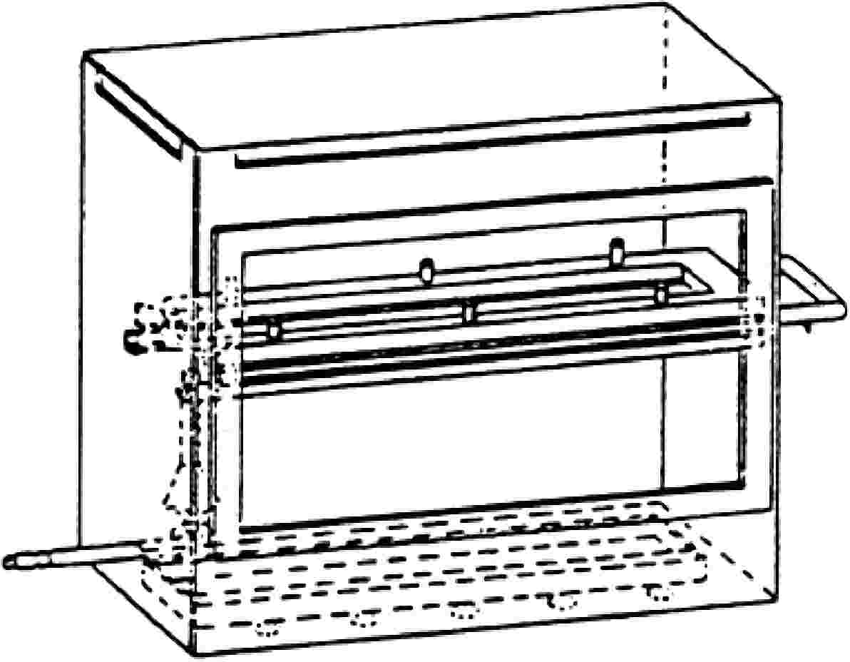
Figure 15 — Example of combustion chamber with sample-holder and drip pan 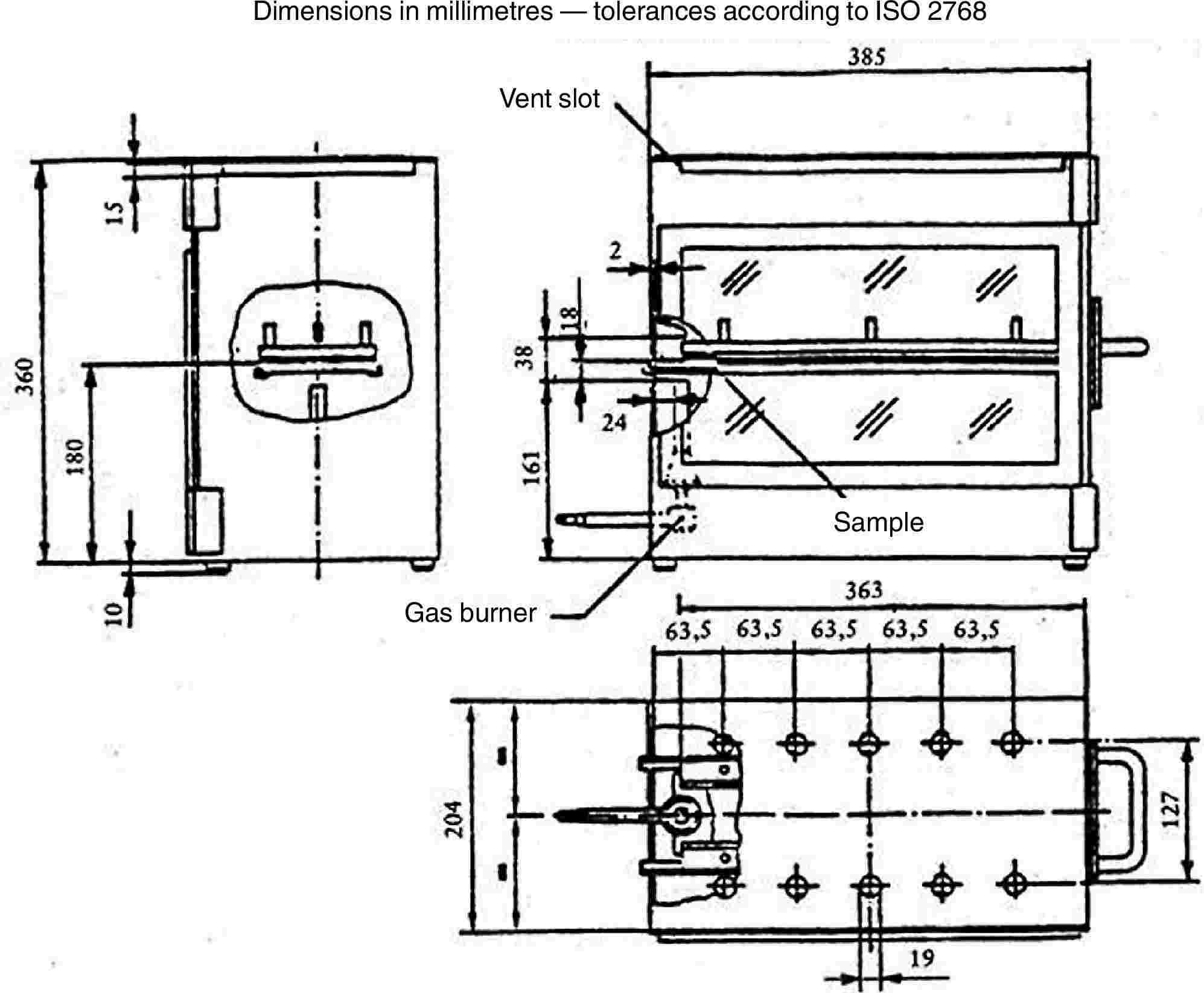
Figure 16 — Example of combustion chamber 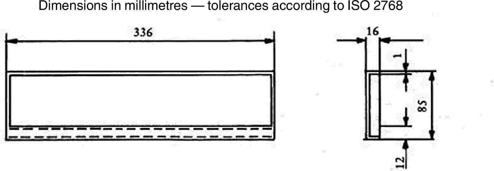
Figure 17 — Typical drip pan |
|
10.4.2. |
Sample holder, consisting of two U-shaped metal plates or frames of corrosion-proof material. Dimensions are given in Figure 18. The lower plate is equipped with pins and the upper one with corresponding holes, in order to ensure a consistent holding of the sample. The pins also serve as measuring points at the beginning and end of the burning distance. A support is provided in the form of heat-resistant wires 0,25 mm in diameter spanning the frame at 25 mm intervals over the bottom U-shaped frame (see Figure 19). 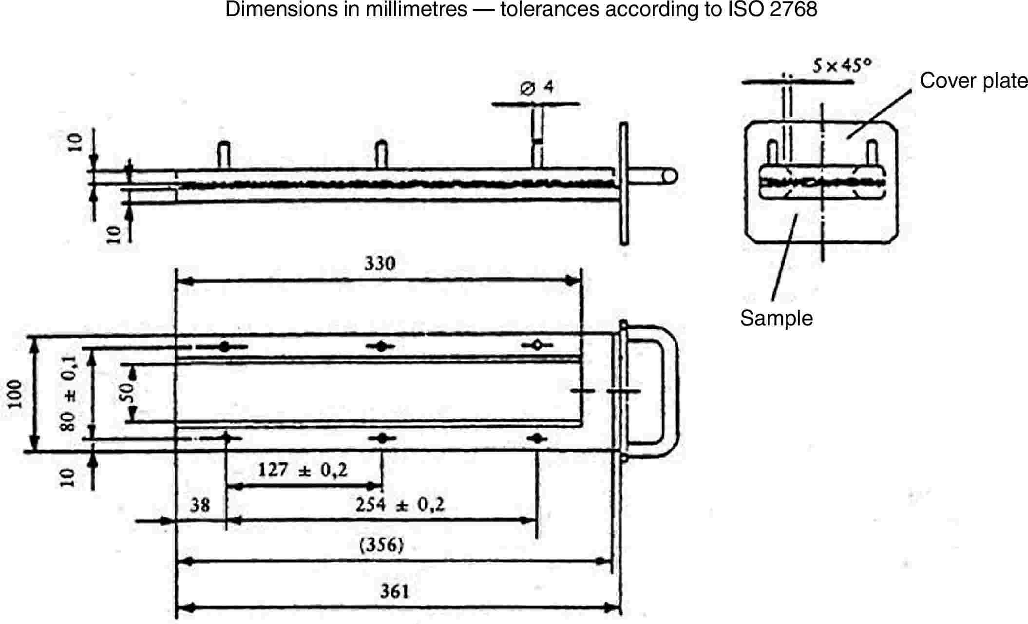
Figure 18 — Example of sample holder 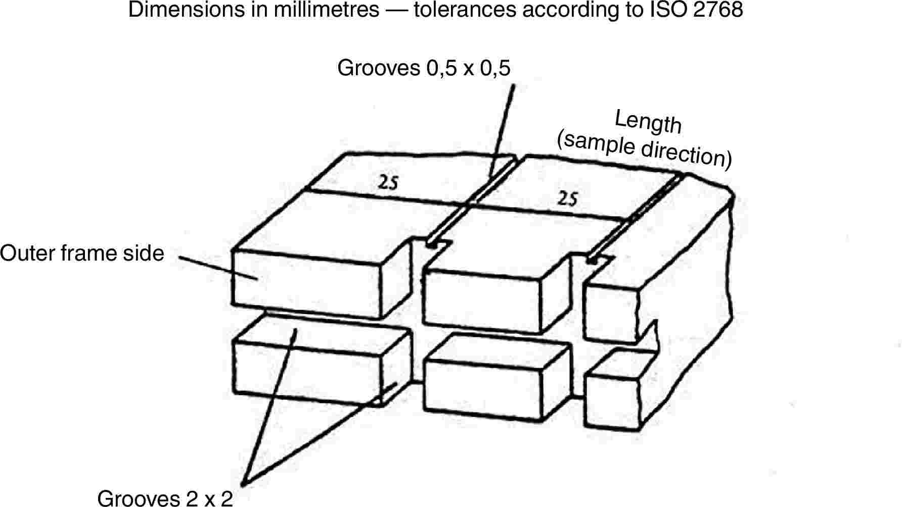
Figure 19 — Example of section of lower U-frame design for wire support facility The plane of the lower side of samples must be 178 mm above the floor plate. The distance of the front edge of the sample holder from the end of the chamber must be 22 mm; the distance of the longitudinal sides of the sample holder from the sides of the chamber must be 50 mm (all inside dimensions). (See Figures 15 and 16.) |
|
10.4.3. |
Gas burner. The small ignition source is provided by a Bunsen burner having an inside diameter of 9,5 mm. It is so located in the test cabinet that the centre of its nozzle is 19 mm below the centre of the bottom edge of the open end of the sample (see Figure 16). |
|
10.4.4. |
Test gas. The gas supplied to the burner must have a calorific value of about 38 MJ/m3 (for example natural gas). |
|
10.4.5. |
Metal comb, at least 110 mm in length, with seven or eight smooth rounded teeth per 25 mm. |
|
10.4.6. |
Stop-watch, accurate to 0,5 second. |
|
10.4.7. |
Fume cupboard. The combustion chamber may be placed in a fume cupboard assembly provided that the latter's internal volume is at least 20 times, but not more than 110 times, greater than the volume of the combustion chamber and provided that no single height, width, or length dimension of the fume cupboard is greater than 2,5 times either of the other two dimensions. Before the test, the vertical velocity of the air through the fume cupboard is measured 100 mm forward of and to the rear of the ultimate site of the combustion chamber. It must be between 0,10 and 0,30 m/s in order to avoid possible discomfort to the operator from combustion products. It is possible to use a fume cupboard with natural ventilation and an appropriate air velocity. |
10.5. Samples
10.5.1. Shape and dimensions
The shape and dimensions of samples are given in Figure 20. The thickness of the sample corresponds to the thickness of the product to be tested. It must not be more than 13 mm. When sample taking so permits, the sample must have a constant section over its entire length. When the shape and dimensions of a product do not permit taking a sample of the given size, the following minimum dimensions must be observed:
(a) for samples having a width of 3 to 60 mm, the length must be 356 mm. In this case the material is tested over the product's width;
(b) for samples having a width of 60 to 100 mm, the length must be at least 138 mm. In this case the potential burning distance corresponds to the length of the sample, the measurement starting at the first measuring point;
(c) samples less than 60 mm wide and less than 356 mm long, and samples 60 to 100 mm wide and less than 138 mm long, cannot be tested according to the present method, nor can samples less than 3 mm wide.
10.5.2. Sampling
At least five samples are to be taken from the material under test. In materials having burning rates differing according to the direction of the material (this being established by preliminary tests) the five (or more) samples are to be taken and placed in the test apparatus in such a way that the highest burning rate will be measured. When the material is supplied in set widths, a length of at least 500 mm covering the entire width is cut. From the piece so cut, the samples are to be taken at not less than 100 mm from the edge of the material and at points equidistant from each other.
Samples are to be taken in the same way from finished products when the shape of the product so permits. If the thickness of the product is over 13 mm it must be reduced to 13 mm by a mechanical process applied to the side which does not face the passenger compartment.
Composite materials (see point 10.2.2) are to be tested as if they were homogeneous.
In the case of materials comprising superimposed layers of different composition which are not composite materials, all the layers of material included within a depth of 13 mm from the surface facing towards the passenger compartment are to be tested individually.
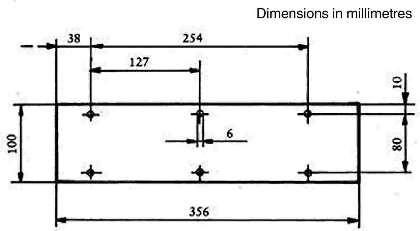
Figure 20 — Sample
10.5.3. Conditioning
The samples are to be conditioned for at least 24 hours, but no more than 7 days, at a temperature of 23 ± 2 °C and a relative humidity of 50 ± 5 %, and maintained under these conditions until immediately prior to testing.
10.6. Procedure
|
10.6.1. |
Place samples with napped or tufted surfaces on a flat surface, and comb twice against the nap using the comb (10.4.5). |
|
10.6.2. |
Place the sample in the sample holder (10.4.2) so that the exposed side faces downwards, towards the flame. |
|
10.6.3. |
Adjust the gas flame to a height of 30 mm using the mark in the chamber, the air intake of the burner being closed. The flame must burn for at least one minute, for stabilisation, before the first test is started. |
|
10.6.4. |
Push the sample holder into the combustion chamber so that the end of the sample is exposed to the flame, and after 15 seconds cut off the gas flow. |
|
10.6.5. |
Measurement of burning time starts at the moment when the foot of the flame passes the first measuring point. Observe the flame propagation on the side (upper or lower) which burns faster. |
|
10.6.6. |
Measurement of burning time is completed when the flame has come to the last measuring point or when the flame is extinguished before reaching that point. If the flame does not reach the last measuring point, measure the burnt distance up to the point where the flame was extinguished. Burnt distance is the part of the sample destroyed, on the surface or inside, by burning. |
|
10.6.7. |
If the sample does not ignite or does not continue burning after the burner has been extinguished, or the flame goes out before reaching the first measuring point, so that no burning time is measured, note in the test report that the burning is 0 mm/minute. |
|
10.6.8. |
When running a series of tests or performing repeat tests, make sure before starting a test that the temperature of the combustion chamber and sample-holder does not exceed 30 °C. |
10.7. Calculation
The burning rate, B, in millimetres per minute, is given by the formula:
B = (s/t) × 60
where:
|
s |
is the burnt distance, in millimetres, |
|
t |
is the time, in seconds, taken to burn the distance s. |
10.8. Indices of difficulty of the secondary characteristics
No secondary characteristics are involved.
10.9. Interpretation of results
Plastic-coated (2.3) and plastic safety glazing (2.4) are considered satisfactory from the point of view of burning behaviour (fire resistance) if the burn rate does not exceed 250 mm/minute.
11. TESTING OF RESISTANCE TO CHEMICAL AGENTS
11.1. Chemical agents to be used
|
11.1.1. |
Non-abrasive soapy solution: 1 % by weight of potassium oleate in de-ionised water. |
|
11.1.2. |
Window-cleaning product: aqueous solution of isopropanol and dipropylene glycol monomethyl ether, each at a concentration of 5 % to 10 % by weight, and of ammonium hydroxyde at a concentration of 1 % to 5 % by weight. |
|
11.1.3. |
Non-dilute denatured alcohol: one part by volume of methyl alcohol in 10 parts by volume of ethyl alcohol. |
|
11.1.4. |
Reference gasoline mixture of 50 % by volume of toluene, 30 % by volume of 2,2,4-trimethylpentane, 15 % by volume of 2,4,4-trimethyl-1-pentane and 5 % by volume of ethyl alcohol. |
|
11.1.5. |
Reference kerosene: mixture of 50 % by volume of n-octane and 50 % by volume of n-decane. |
11.2. Test method
Two 180 × 25 mm test pieces are each to be tested with chemical agents as provided for in point 11.1, a new test piece being used for each test and product. After each test the pieces are to be cleaned in accordance with the manufacturer's instruction, and then conditioned for 48 hours at a temperature of 23 ± 2 °C and a relative humidity of 50 ± 5 %. These conditions are to be maintained during the tests. The test pieces are to be completely immersed in the test liquid for one minute, withdrawn and then immediately dried with a (clean) absorbent cotton cloth.
11.3. Indices of difficulty of the secondary characteristics
|
Colourless |
Tinted |
|
|
Colouring of the plastic interlayer, or coating |
1 |
2 |
No secondary characteristic is involved.
11.4. Interpretation of the results
|
11.4.1. |
The test for resistance to chemical agents is considered to be positive if the test pieces display no softening, stickiness, surface cracking or apparent loss of transparency. |
|
11.4.2. |
A series of test pieces submitted for component type-approval is considered satisfactory as regards resistance to chemical agents if one of the following conditions has been met:
|
ANNEX III D
Toughened-glass windscreens
1. DEFINITION OF TYPE
Toughened-glass windscreens are deemed to belong to different types if they differ in at least one of the following principal or secondary characteristics.
1.1. The principal characteristics are as follows:
|
1.1.1. |
the trade name or mark; |
|
1.1.2. |
the shape and dimensions. Toughened-glass windscreens are considered as belonging to one or other of two groups for the purposes of the fragmentation and mechanical-properties tests, i.e.:
|
|
1.1.3. |
the thickness category in which the nominal thickness ‘e’ lies (a manufacturing tolerance of ± 0,2 mm being allowed):
|
1.2. The secondary characteristics are as follows:
|
1.2.1. |
nature of the material (polished (plate) glass, float glass, sheet glass), |
|
1.2.2. |
colouring (colourless or tinted), |
|
1.2.3. |
the incorporation or absence of conductors, |
|
1.2.4. |
the incorporation or absence of obscuration bands. |
2. FRAGMENTATION TEST
2.1. Indices of difficulty of the secondary characteristics
|
2.1.1. |
Only the nature of the material is involved. |
|
2.1.2. |
Float glass and sheet glass are considered to have the same index of difficulty. |
|
2.1.3. |
The fragmentation tests must be repeated on transition from polished (plate) glass to float glass or sheet glass, and vice versa. |
|
2.1.4. |
The tests must be repeated if obscuration bands other than painted bands are used. |
2.2. Number of samples
Six samples from the smallest-developed-area series and six samples from the largest-developed-area series, selected as prescribed in Annex III M, are to be tested.
2.3. Different zones of glass
A toughened-glass windscreen must comprise two main zones, FI and FII. It may also comprise an intermediate zone, FIII.
These zones are as defined below:
|
2.3.1. |
zone FI: peripheral zone of fine fragmentation, at least 7 cm wide, all round the edge of the windscreen and including an outer strip 2 cm wide not subjected to assessment; |
|
2.3.2. |
zone FII: visibility zone of varying fragmentation, always including a rectangular part at least 20 cm high and 50 cm long.
|
|
2.3.3. |
zone FIII: intermediate zone, not more than 5 cm wide, between zones FI and FII. |
2.4. Test method
The method used is that described in point 1 of Annex III C.
2.5. Points of impact (see Annex III N, Figure 2)
|
2.5.1. |
The points of impact are selected as follows: point 1: in the central part of zone FII in an area of high or low stress; point 2: in zone FIII, as near as possible to the vertical plane of symmetry of zone FII; points 3 and 3′: 3 cm from the edges of one median of the sample; when there is a tong mark, one of the breakage points shall be near the edge bearing the tong mark and the other near the opposite edge; point 4: at the place where the radius of curvature is smallest on the longest median; point 5: 3 cm from the edge of the sample at the place where the radius of curvature of the edge is smallest, either to the left or to the right. |
|
2.5.2. |
A fragmentation test is performed at each of the points 1, 2, 3, 3′, 4 and 5. |
2.6. Interpretation of results
|
2.6.1. |
A test is deemed to have given a satisfactory result if fragmentation satisfies all the conditions given in points 2.6.1.1, 2.6.1.2 and 2.6.1.3 below. 2.6.1.1. Zone FI
2.6.1.2. Zone FII
2.6.1.3. Zone FIII Fragmentation in this zone must have characteristics intermediate between those of the fragmentations respectively allowed for the two neighbouring zones (FI and FII). |
|
2.6.2. |
A windscreen submitted for component type-approval is considered satisfactory from the point of view of fragmentation if at least one of the following conditions is fulfilled:
|
|
2.6.3. |
If the abovementioned deviations are found, they must be noted in the test report and photographs of the relevant parts of the windscreen attached to the report. |
3. HEADFORM TEST
3.1. Indices of difficulty of the secondary characteristics
No secondary characteristic is involved.
3.2. Number of samples
|
3.2.1. |
For each group of toughened-glass windscreens, four samples having approximately the smallest developed area and four samples having approximately the largest developed area, all eight samples being of the same types as those selected for the fragmentation tests (see point 2.2) are subjected to testing. |
|
3.2.2. |
Alternatively, at the discretion of the laboratory conducting the tests, for each category of windscreen thickness, six test pieces of the dimension (1 100 × 500 mm) + 5/– 2 mm are subjected to testing. |
3.3. Test method
|
3.3.1. |
The method used is that described in point 3 of Annex III C. |
|
3.3.2. |
The height of drop is 1,50 m + 0/– 5 mm. |
3.4. Interpretation of results
|
3.4.1. |
The test is deemed to have given a satisfactory result if the windscreen or the test piece is fractured. |
|
3.4.2. |
A set of samples submitted for component type-approval is considered satisfactory from the point of view of the headform test if either of the two following conditions is fulfilled:
|
4. OPTICAL QUALITIES
The requirements concerning optical qualities set out in point 9 of Annex III C apply to every type of windscreen.
ANNEX III E
Uniformly toughened glass panes other than windscreens ( 29 )
1. DEFINITION OF TYPE
Uniformly toughened glass panes are deemed to belong to different types if they differ in at least one of the following principal or secondary characteristics.
1.1. The principal characteristics are as follows:
|
1.1.1. |
the trade name or mark; |
|
1.1.2. |
the nature of the toughening process (thermal or chemical); |
|
1.1.3. |
the shape category; two categories are distinguished:
|
|
1.1.4. |
the thickness category in which the nominal thickness ‘e’ lies (a manufacturing tolerance of ± 0,2 mm being allowed):
|
1.2. The secondary characteristics are as follows:
|
1.2.1. |
nature of the material (polished (plate) glass, float glass, sheet glass), |
|
1.2.2. |
colouring (colourless or tinted), |
|
1.2.3. |
the incorporation or absence of conductors. |
2. FRAGMENTATION TEST
2.1. Indices of difficulty of the secondary characteristics
|
Material |
Index of difficulty |
|
Plate glass |
2 |
|
Float glass |
1 |
|
Sheet glass |
1 |
No other secondary characteristics are involved.
2.2. Selection of samples
|
2.2.1. |
Samples of each shape category and of each thickness category difficult to produce are selected according to the following criteria for testing:
|
|
2.2.2. |
Tests carried out on samples corresponding to the largest area, S, are considered to be applicable to any other area smaller than S + 5 %. |
|
2.2.3. |
If the samples submitted present an angle, γ, smaller than 30°, the tests are considered as applicable to all glass panes produced having an angle greater than γ – 5°. If the samples submitted present an angle, γ, greater than or equal to 30°, the tests are considered as applicable to all glass panes produced having an angle equal to or greater than 30°. |
|
2.2.4. |
If the height of segment, h, of the samples submitted is greater than 100 mm, the tests are considered as applicable to all glass panes produced having a height of segment smaller than h + 30 mm. If the height of segment of the samples submitted is less than or equal to 100 mm, the tests are considered as applicable to all glass panes having a height of segment less than or equal to 100 mm. |
2.3. Number of samples per set
The number of samples in each group shall be as follows, according to the shape category defined in point 1.1.3 above:
|
Kind of glass pane |
Number of samples |
|
Flat (two sets) |
4 |
|
Flat and curved (three sets) |
5 |
2.4. Test method
|
2.4.1. |
The method used is that described in point 1 of Annex III C. |
2.5. Points of impact (see Annex III N, Figure 3)
|
2.5.1. |
For flat glass panes and curved glass panes the points of impact represented respectively in Annex III N, Figures 3 (a) and 3 (b) on the one hand, and in Annex III N, Figure 3 (c) on the other hand, are as follows: point 1: 3 cm from the edges of the glass pane in the part where the radius of curvature of the edge is smallest; point 2: 3 cm from the edge of one of the medians, the side (if any) of the glass pane bearing tong marks being selected; point 3: in the geometric centre of the glass; point 4: for curved glass panes only; this point is selected on the largest median in that part of the pane where the radius of curvature is smallest. |
|
2.5.2. |
Only one test is carried out at each prescribed point of impact. |
2.6. Interpretation of results
|
2.6.1. |
A test is deemed to have given a satisfactory result if fragmentation satisfies the following conditions:
|
|
2.6.2. |
A set of samples submitted for component type-approval is considered satisfactory from the point of view of fragmentation if at least one of the following conditions is fulfilled:
|
|
2.6.3. |
If the abovementioned deviations are found, they must be noted in the test report and photographs of the relevant parts of the glass pane attached to the report. |
3. MECHANICAL STRENGTH TEST
3.1. 227-g-ball test
3.1.1. Indices of difficulty of the secondary characteristics
|
Material |
Index of difficulty |
Colouring |
Index of difficulty |
|
Polished glass |
2 |
colourless |
1 |
|
Float glass |
1 |
tinted |
2 |
|
Sheet glass |
1 |
The other secondary characteristic (namely, incorporation or absence of conductors) is not involved.
3.1.2. Number of test pieces
Six test pieces are subjected to testing for each thickness category defined in point 1.1.4 above.
3.1.3. Test method
|
3.1.3.1. |
The test method used is that described in point 2.1 of Annex III C. |
|
3.1.3.2. |
The height of drop (from the underface of the ball to the upper surface of the test piece) is indicated in the following table, according to thickness of the glass pane:
|
3.1.4. Interpretation of results
|
3.1.4.1. |
The test is deemed to have given a satisfactory result if the test piece does not break. |
|
3.1.4.2. |
A set of test pieces submitted for component type-approval is considered satisfactory from the point of view of mechanical strength if at least one of the following conditions is fulfilled:
|
4. OPTICAL QUALITIES
4.1. Light transmittance
The requirements concerning regular light transmittance set out in point 9.1 of Annex III C apply to uniformly toughened glass panes or parts of glass panes located at places which are essential to the driver's vision.
ANNEX III F
Ordinary laminated-glass windscreens
1. DEFINITION OF TYPE
Ordinary laminated-glass windscreens are deemed to belong to different types if they differ in at least one of the following principal or secondary characteristics.
1.1. The principal characteristics are as follows:
|
1.1.1. |
the trade name or mark; |
|
1.1.2. |
the shape and dimensions. Ordinary laminated-glass windscreens are deemed to belong to one group for the purposes of tests of mechanical properties and of resistance to the environment; |
|
1.1.3. |
the number of layers of glass; |
|
1.1.4. |
the nominal thickness ‘e’ of the windscreen, a manufacturing tolerance of 0,2 n mm (n being the number of layers of glass in the windscreen) above or below the nominal value being allowed; |
|
1.1.5. |
the nominal thickness of the interlayer or interlayers; |
|
1.1.6. |
the nature and type of the interlayer or interlayers (e.g. PVB or other plastic-material interlayer or interlayers). |
1.2 The secondary characteristics are as follows:
|
1.2.1. |
the nature of the material (polished (plate) glass, float glass, sheet glass), |
|
1.2.2. |
the colouring (total or partial) of the interlayer or interlayers (colourless or tinted), |
|
1.2.3. |
the colouring of the glass (colourless or tinted), |
|
1.2.4. |
the incorporation or absence of conductors, |
|
1.2.5. |
the incorporation or absence of obscuration bands. |
2. GENERAL
|
2.1. |
In the case of ordinary laminated-glass windscreens, tests other than headform tests (point 3.2) and tests of optical qualities are conducted on flat test pieces which are either cut from actual windscreens or are specially made for the purpose. In either case the test pieces must in all respects be rigorously representative of the production windscreens for which component type-approval is sought. |
|
2.2. |
Before each test, the test pieces must be stored for not less than four hours at a temperature of 23 ± 2 °C. The tests must take place as soon as possible after the test pieces have been taken out of the receptacle in which they were stored. |
3. HEADFORM TEST
3.1. Indices of difficulty of the secondary characteristics
No secondary characteristic is involved.
3.2. Headform test on a complete windscreen
3.2.1. Number of samples
Four samples from the smallest-developed-area series and four samples from the largest-developed-area series, selected in accordance with the provisions of Annex III M, are tested.
3.2.2. Test method
|
3.2.2.1. |
The method used is that described in point 3.3.2 of Annex III C. |
|
3.2.2.2. |
The drop height is 1,5 m + 0/– 5 mm. |
3.2.3. Interpretation of results
|
3.2.3.1. |
This test is deemed to have given a satisfactory result if the following conditions are fulfilled:
|
|
3.2.3.2. |
A set of samples submitted for approval is considered satisfactory from the point of view of the headform test if one of the following two conditions is met:
|
3.3. Headform test on flat test pieces
3.3.1. Number of test pieces
Six flat test pieces measuring (1 100 mm × 500 mm) + 5/– 2 mm are subjected to testing.
3.3.2. Test method
|
3.3.2.1. |
The method used is that described in point 3.3.1 of Annex III C. |
|
3.3.2.2. |
The height of drop is 4 m + 25/– 0 mm. |
3.3.3. Interpretation of results
|
3.3.3.1. |
This test is deemed to have given a satisfactory result if the following conditions are fulfilled:
|
|
3.3.3.2. |
a set of test pieces submitted for approval is considered satisfactory from the point of view of the headform test if one of the following two conditions is met:
|
4. MECHANICAL STRENGTH TEST
4.1. Indices of difficulty of the secondary characteristics
No secondary characteristic is involved.
4.2. 2 260-g-ball test
4.2.1. Number of test pieces
Six square test pieces of 300 mm + 10/– 0 mm side are subjected to testing.
4.2.2. Test method
|
4.2.2.1. |
The method used is that described in point 2.2 of Annex III C. |
|
4.2.2.2. |
The height of drop (from the underface of the ball to the upper face of the test piece) is 4 m + 25/– 0 mm. |
4.2.3. Interpretation of results
|
4.2.3.1. |
The test is deemed to have given a satisfactory result if the ball does not pass through the glazing within five seconds from the moment of impact. |
|
4.2.3.2. |
A set of test pieces submitted for component type-approval is considered satisfactory from the point of view of the 2 260-g-ball test if one of the following two conditions is met:
|
4.3. 227-g-ball test
4.3.1. Indices of difficulty of the secondary characteristics
No secondary characteristic is involved.
4.3.2. Number of test pieces
20 square test pieces of 300 mm + 10/– 0 mm side are subjected to testing.
4.3.3. Test method
|
4.3.3.1. |
The method used is that described in point 2.1 of Annex III C. 10 specimens are tested at a temperature of + 40 ± 2 °C and 10 at a temperature of – 20 ± 2 °C. |
|
4.3.3.2. |
The height of drop for the various thickness categories and the mass of the detached fragments are given in the table below:
|
||||||||||||||||||||||||||||||||||||||||
4.3.4. Interpretation of results
|
4.3.4.1. |
the test is considered to have given a satisfactory result if the following conditions are met: — the ball does not pass through the test piece, — the test piece does not break into several pieces, — if the interlayer is not torn, the weight of fragments detached from the side of the glass opposite to the point of impact must not exceed the appropriate values specified in point 4.3.3.2. |
|
4.3.4.2. |
A set of test pieces submitted for component type-approval is considered satisfactory from the point of view of the 227-g-ball test if one of the following conditions is met:
|
5. TEST OF RESISTANCE TO THE ENVIRONMENT
5.1. Test of resistance to abrasion
5.1.1. Indices of difficulty and test method
The requirements of point 4 of Annex III C apply, the test being continued for 1 000 cycles.
5.1.2. Interpretation of results
The safety-glass pane is considered satisfactory with respect to abrasion resistance if the light scatter as a result of abrasion of the test piece does not exceed 2 %.
5.2. Test of resistance to high temperature
The requirements of point 5 of Annex III C apply.
5.3. Resistance-to-radiation test
5.3.1. General requirement
This test is performed only if the laboratory deems it useful in the light of the information in its possession concerning the interlayer.
|
5.3.2. |
The requirements of point 6 of Annex III C apply. |
5.4. Resistance-to-humidity test
The requirements of point 7 of Annex III C apply.
6. OPTICAL QUALITIES
The requirements concerning optical qualities set out in point 9 of Annex III C apply to every type of windscreen.
ANNEX III G
Laminated-glass panes other than windscreens ( 30 )
1. DEFINITION OF TYPE
Laminated-glass panes other than windscreens are deemed to belong to different types if they differ in at least one of the following principal or secondary characteristics.
1.1. The principal characteristics are as follows:
|
1.1.1. |
the trade name or mark; |
|
1.1.2. |
the thickness category of the pane in which the nominal thickness ‘e’ lies, a manufacturing tolerance of ± 0,2n mm, (n being the number of layers of glass in the pane) being allowed:
|
|
1.1.3. |
the nominal thickness of the interlayer or interlayers; |
|
1.1.4. |
the nature and type of the interlayer or interlayers, e.g. PVB or other plastic-material interlayer or interlayers; |
|
1.1.5. |
any special treatment which one of the layers of glass may have undergone. |
1.2. The secondary characteristics are as follows:
|
1.2.1. |
the nature of the material (polished (plate) glass, float glass, sheet glass), |
|
1.2.2. |
the colouring (total or partial) of the interlayer or interlayers (colourless or tinted), |
|
1.2.3. |
the colouring of the glass (colourless or tinted). |
2. GENERAL
|
2.1. |
In the case of laminated-glass panes other than windscreens, the tests are conducted on flat test pieces which are either cut from actual glass panes or are specially made. In either case the test pieces must in all respects be rigorously representative of the glass panes for the production of which component type-approval is sought. |
|
2.2. |
Before each test, the test pieces of laminated glass must be stored for not less than 4 hours at a temperature of 23 ± 2 °C. The tests are performed on the test pieces as soon as the pieces have been taken out of the receptacle in which they were stored. |
|
2.3. |
The provisions of this Annex are considered to be met if the glazing submitted for component type-approval is of the same composition as a windscreen already approved under the provisions of Annex III F, III H or III I. |
3. HEADFORM TEST
3.1. Indices of difficulty of the secondary characteristics
No secondary characteristic is involved.
3.2. Number of test pieces
Six flat test pieces measuring 1 100 × 500 mm (+ 25/– 0 mm) are subjected to testing.
3.3. Test method
|
3.3.1. |
The method used is that described in point 3 of Annex III C. |
|
3.3.2. |
The height of drop is 1,50 m + 0/– 5 mm. This is increased to 4 m + 25/– 0 mm for glass panes used as tractor windscreens. |
3.4. Interpretation of results
|
3.4.1. |
This test is deemed to have given a satisfactory result if the following conditions are met:
|
|
3.4.2. |
A set of test pieces subjected to component type-approval testing is considered satisfactory from the point of view of the headform test if one of the following two conditions is met:
|
4. MECHANICAL STRENGTH TEST — 227-g-BALL TEST
4.1. Indices of difficulty of the secondary characteristics
No secondary characteristic is involved.
4.2. Number of test pieces
Four flat square test pieces of side 300 mm (+ 10/– 0 mm) must be subjected to tests.
4.3. Test method
|
4.3.1. |
The method used is that described in point 2.1 of Annex III C. |
|
4.3.2. |
The height of drop (from the underface of the ball to the upper face of the test piece) is as indicated in the following table as a function of nominal thickness:
|
||||||||||
4.4. Interpretation of results
|
4.4.1. |
The test is considered to have given a satisfactory result if the following conditions are met: — the ball does not pass through the test piece, — the test piece does not break into several fragments, — the total weight of the few fragments which may be produced on the side opposite to the point of impact does not exceed 15 g. |
|
4.4.2. |
A set of test pieces subjected to component type-approval testing is considered satisfactory from the point of view of mechanical strength if one of the following conditions is met:
|
5. TEST OF RESISTANCE TO THE ENVIRONMENT
5.1. Test of resistance to abrasion
5.1.1. Indices of difficulty and test method
The requirements of point 4 of Annex III C apply, the test being continued for 1 000 cycles.
5.1.2. Interpretation of results
The safety-glass pane is considered satisfactory from the point of view of abrasion resistance if the light scatter as a result of abrasion of the test piece does not exceed 2 %.
5.2. Test of resistance to high temperature
The requirements of point 5 of Annex III C apply.
5.3. Resistance-to-radiation test
5.3.1. General requirement
This test is performed only if the laboratory deems it useful in the light of the information in its possession concerning the interlayer.
|
5.3.2. |
The requirements of point 6 of Annex III C apply. |
5.4. Resistance-to-humidity test
|
5.4.1. |
The requirements of point 7 of Annex III C apply. |
6. OPTICAL QUALITIES
6.1. Light transmittance
The provisions concerning the regular light transmittance set out in point 9.1 of Annex III C apply to glass panes other than windscreens, or parts of glass panes located at places which are essential to the driver's vision.
ANNEX III H
Treated laminated-glass windscreens
1. DEFINITION OF TYPE
Treated laminated-glass windscreens are deemed to belong to different types if they differ in at least one of the following principal or secondary characteristics.
1.1. The principal characteristics are as follows:
|
1.1.1. |
the trade name or mark; |
|
1.1.2. |
the shape and dimensions. Treated laminated-glass windscreens are deemed to belong to one group for the purposes of the fragmentation, mechanical properties and resistance to the environment tests; |
|
1.1.3. |
the number of layers of glass; |
|
1.1.4. |
the nominal thickness ‘e’ of the windscreen, a manufacturing tolerance of 0,2 n mm, (n being the number of layers of glass in the windscreen) above and below the nominal value being allowed; |
|
1.1.5. |
any special treatment which one or more layers of glass may have undergone; |
|
1.1.6. |
the nominal thickness of the interlayer or interlayers; |
|
1.1.7. |
the nature and type of the interlayer or interlayers (e.g. PVB or other plastic-material interlayer or interlayers). |
1.2. The secondary characteristics are as follows:
|
1.2.1. |
the nature of the material (polished (plate) glass, float glass, sheet glass), |
|
1.2.2. |
the colouring (total or partial) of the interlayer or interlayers (colourless or tinted), |
|
1.2.3. |
the colouring of the glass (colourless or tinted), |
|
1.2.4. |
the incorporation or absence of conductors, |
|
1.2.5. |
the incorporation or absence of obscuration bands. |
2. GENERAL
|
2.1. |
In the case of treated laminated-glass windscreens, tests other than the headform test on a complete windscreen and tests of optical qualities are conducted on samples and/or flat test pieces which are specially made for the purpose. However, the test pieces must in all respects be rigorously representative of the production windscreens for which component type-approval is sought. |
|
2.2. |
Before each test, the test pieces or samples must be stored for not less than 4 hours at a temperature of 23 ± 2 °C. The tests must take place as soon as possible after the test pieces or samples have been taken out of the receptacle in which they were stored. |
3. TESTS PRESCRIBED
Treated laminated-glass windscreens are to be subjected to:
|
3.1. |
the tests prescribed in Annex III F for ordinary laminated-glass windscreens, |
|
3.2. |
the fragmentation test described in point 4 below. |
4. FRAGMENTATION TEST
4.1. Indices of difficulty of the secondary characteristics
|
Material |
Index of difficulty |
|
Plate glass |
2 |
|
Float glass |
1 |
|
Sheet glass |
1 |
4.2. Number of test pieces or samples
One test piece measuring 1 100 × 500 mm (+ 5/– 2 mm) or one sample for each point of impact is subjected to testing.
4.3. Test method
The method used is that described in point 1 of Annex III C.
4.4. Impact point or points
The glass pane is struck on each of the outer treated sheets in the centre of the test piece or sample.
4.5. Interpretation of results
|
4.5.1. |
For each point of impact the fragmentation test is considered to have given a satisfactory result if the total surface of fragments having a surface area of more than 2 cm2 comprised in a rectangle as defined in point 2.3.2 of Annex III D represents not less than 15 % of the surface of that rectangle.
|
|
4.5.2. |
The test piece(s) or sample(s) submitted for component type-approval are considered satisfactory from the point of view of fragmentation if either of the following conditions is met:
|
ANNEX III I
Safety-glass panes faced with plastic material on the inside
|
1. |
Safety glazing materials, as defined in Annexes III D to III H, if coated on the inner face with a layer of plastic material, must conform not only to the requirements of the appropriate Annexes but also to the following requirements. |
|
2. |
TEST OF RESISTANCE TO ABRASION 2.1. Indices of difficulty and test method The plastic coating is to be subjected to a test for 100 cycles in accordance with the requirements specified in point 4 of Annex III C. 2.2. Interpretation of results The plastic coating is considered satisfactory with respect to abrasion resistance if the light scatter as a result of abrasion of the test piece does not exceed 4 %. |
|
3. |
RESISTANCE-TO-HUMIDITY TEST
|
|
4. |
TEST OF RESISTANCE TO TEMPERATURE CHANGES The requirements of point 8 of Annex III C apply. |
|
5. |
FIRE-RESISTANCE TEST The requirements of point 10 of Annex III C apply. |
|
6. |
TEST OF RESISTANCE TO CHEMICALS The requirements of point 11 of Annex III C apply. |
ANNEX III J
Glass-plastic windscreens
1. DEFINITION OF TYPE
Glass-plastic windscreens are considered to belong to different types if they differ in at least one of the following principal or secondary characteristics.
1.1. The principal characteristics are as follows:
|
1.1.1. |
the trade name or mark; |
|
1.1.2. |
the shape and dimensions. Glass-plastic windscreens are deemed to belong to a group for the purposes of tests of mechanical strength, resistance to the environment, resistance to temperature changes and resistance to chemical agents; |
|
1.1.3. |
the number of plastic layers; |
|
1.1.4. |
the nominal thickness ‘e’ of the windscreen, a manufacturing tolerance of ± 0,2 mm being allowed; |
|
1.1.5. |
the nominal thickness of the layer of glass; |
|
1.1.6. |
the nominal thickness of the layer(s) of plastic acting as interlayer(s); |
|
1.1.7. |
the nature and type of the layer(s) of plastic acting as interlayer(s) (e. g. PVB or other material) and of the plastic layer situated on the inner face; |
|
1.1.8. |
any special treatment the glass pane may have undergone. |
1.2. The secondary characteristics are as follows:
|
1.2.1. |
the nature of the material (plate glass, float glass, sheet glass), |
|
1.2.2. |
the colouring (total or partial) of any layer(s) of plastic (colourless or tinted), |
|
1.2.3. |
the colouring of the glass (colourless or tinted), |
|
1.2.4. |
the incorporation or absence of conductors, |
|
1.2.5. |
the incorporation or absence of obscuration bands. |
2. GENERAL
|
2.1. |
In the case of glass-plastic windscreens, tests other than headform tests (3.2) and tests of optical qualities are conducted on flat test pieces which are either cut from actual windscreens or are specially made for the purpose. In either case the test pieces must in all respects be rigorously representative of the production windscreens for which component type-approval is sought. |
|
2.2. |
Before each test, the test pieces must be stored for not less than 4 hours at a temperature of 23 ± 2 °C. The tests must take place as soon as possible after the test pieces have been taken out of the receptacle in which they were stored. |
3. HEADFORM TEST
3.1. Indices of difficulty of the secondary characteristics
No secondary characteristic is involved.
3.2. Headform test on a complete windscreen
3.2.1. Number of samples
Four samples from the series having the smallest developed area and four samples from the series having the largest developed area, selected in accordance with the provisions of Annex III M, are tested.
3.2.2. Test method
|
3.2.2.1. |
The method used is that described in point 3.3.2 of Annex III C. |
|
3.2.2.2. |
The height of drop is 1,50 m + 0/– 5 mm. |
3.2.3. Interpretation of results
|
3.2.3.1. |
This test is considered to have given a satisfactory result if the following conditions are met:
|
|
3.2.3.2. |
A set of test pieces submitted for component type-approval is considered satisfactory with respect to the headform test if one of the following two conditions is met:
|
3.3. Headform test on flat test pieces
3.3.1. Number of test pieces
Six flat test pieces measuring 1 100 × 500 mm (+ 5/– 2 mm) are subjected to testing.
3.3.2. Test method
|
3.3.2.1. |
The method used is that described in point 3.3.1 of Annex III C. |
|
3.3.2.2. |
The height of drop is 4 m + 25/– 0 mm. |
3.3.3. Interpretation of results
|
3.3.3.1. |
This test is considered to have given a satisfactory result if the following conditions are met:
|
|
3.3.3.2. |
A set of test pieces submitted for component type-approval is considered satisfactory with respect to the headform test if one of the following conditions is met:
|
4. MECHANICAL STRENGTH TEST
4.1. Indices of difficulty, test method and interpretation of results
The requirements of point 4 of Annex III F apply.
|
4.2. |
However, the third requirement set out in point 4.3.4.1 of Annex III F is not relevant. |
5. TEST OF RESISTANCE TO THE ENVIRONMENT
5.1. Test of resistance to abrasion
5.1.1. Test of resistance to abrasion on the outer face
|
5.1.1.1. |
The requirements of point 5.1 of Annex III F apply. |
5.1.2. Test of resistance to abrasion on the inner face
|
5.1.2.1. |
The requirements of point 2 of Annex III I apply. |
5.2. Test of resistance to high temperature
The requirements of point 5 of Annex III C apply.
5.3. Resistance-to-radiation test
The requirements of point 6 of Annex III C apply.
5.4. Resistance-to-humidity test
The requirements of point 7 of Annex III C apply.
5.5. Test of resistance to temperature changes
The requirements of point 8 of Annex III C apply.
6. OPTICAL QUALITIES
The requirements concerning optical qualities set out in point 9 of Annex III C apply to each type of windscreen.
7. FIRE-RESISTANCE TEST
The requirements of point 10 of Annex III C apply.
8. TEST OF RESISTANCE TO CHEMICALS
The requirements of point 11 of Annex III C apply.
ANNEX III K
Glass-plastic panes other than windscreens ( 31 )
1. DEFINITION OF TYPE
Glass-plastic panes other than windscreens are considered to belong to different types if they differ in at least one of the following principal or secondary characteristics.
1.1. The principal characteristics are as follows:
|
1.1.1. |
the trade name or mark; |
|
1.1.2. |
the thickness category applicable to the nominal thickness ‘e’, a manufacturing tolerance of ± 0,2 mm being allowed:
|
|
1.1.3. |
the nominal thickness of the layer(s) of plastic material acting as interlayer(s); |
|
1.1.4. |
the nominal thickness of the glass pane; |
|
1.1.5. |
the type of the layer(s) of plastic material acting as interlayer(s) (e.g. PVB or other material) and of the plastic layer on the inner face; |
|
1.1.6. |
any special treatment which the layer of glass may have undergone. |
1.2. The secondary characteristics are as follows:
|
1.2.1. |
the nature of the material (plate glass, float glass, sheet glass), |
|
1.2.2. |
the colouring (total or partial) of any layer(s) of plastic (colourless or tinted), |
|
1.2.3. |
the colouring of the glass (colourless or tinted). |
2. GENERAL
|
2.1. |
In the case of glass-plastic panes other than windscreens the tests are conducted on flat test pieces which are either cut from normal glass panes or are specially made. In either case the test pieces must in all respects be rigorously representative of the production glass panes for which component type-approval is sought. |
|
2.2. |
Before each test, the test pieces of glass-plastic panes must be stored for not less than 4 hours at a temperature of 23 ± 2 °C. The tests must take place as soon as possible after the test pieces have been taken out of the receptacle in which they were stored. |
|
2.3. |
The provisions of this Annex are considered to be met if the glass pane submitted for component type-approval has the same composition as that of a windscreen already approved under the provisions of Annex III J. |
3. HEADFORM TEST
3.1. Indices of difficulty of the secondary characteristics
No secondary characteristic is involved.
3.2. Number of test pieces
Six flat test pieces measuring 1 100 × 500 mm (+ 5/– 2 mm) are subjected to testing.
3.3. Test method
|
3.3.1. |
The method used is that described in point 3 of Annex III C. |
|
3.3.2. |
The height of drop is 1,50 m + 0/– 5 mm. (This height is increased to 4 m + 25/– 0 mm for glass panes used as tractor windscreens.) |
3.4. Interpretation of results
|
3.4.1. |
This test is considered to have given a satisfactory result if the following conditions are met:
|
|
3.4.2. |
A set of test pieces submitted for component type-approval is considered satisfactory with respect to the headform test if one of the following conditions is met:
|
4. MECHANICAL STRENGTH TEST — 227-g-BALL TEST
|
4.1. |
The provisions of point 4 of Annex III G apply, with the exception of the table in point 4.3.2, which is replaced by:
|
||||||||||
|
4.2. |
However, the requirement in the third indent of point 4.4.1 of Annex III G is not relevant. |
5. TEST OF RESISTANCE TO THE ENVIRONMENT
5.1. Test of resistance to abrasion
5.1.1. Test of resistance to abrasion on the outer face
The requirements of point 5.1 of Annex III G apply.
5.1.2. Test of resistance to abrasion on the inner face
The requirements of point 2.1 of Annex III I apply.
5.2. Test of resistance to high temperature
The requirements of point 5 of Annex III C apply.
5.3. Resistance-to-radiation test
The requirements of point 6 of Annex III C apply.
5.4. Resistance-to-humidity test
The requirements of point 7 of Annex III C apply.
5.5. Test of resistance to temperature changes
The requirements of point 8 of Annex III C apply.
6. OPTICAL QUALITIES
The requirements concerning the regular light transmittance set out in point 9.1 of Annex III C apply to glass panes or parts of glass panes located at places which are essential to the driver's vision.
7. FIRE-RESISTANCE TEST
The requirements of point 10 of Annex III C apply.
8. TEST RESISTANCE TO CHEMICALS
The requirements of point 11 of Annex III C apply.
ANNEX III L
Double-glazed units
1. DEFINITION OF TYPE
Double-glazed units are considered to belong to different types if they differ in at least one of the following principal or secondary characteristics.
1.1. The principal characteristics are as follows:
|
1.1.1. |
the trade name or mark; |
|
1.1.2. |
the composition of the double-glazed unit (symmetrical, asymmetrical); |
|
1.1.3. |
the type of each component glass pane as defined in point 1 of Annex III E, III G or III K; |
|
1.1.4. |
the nominal width of the gap between the two glass panes; |
|
1.1.5. |
the type of sealing (organic, or glass to glass/glass to metal). |
1.2. The secondary characteristics are:
|
1.2.1. |
The secondary characteristics of each component glass pane, as defined in point 1.2 of Annex III E, III G or III K. |
2. GENERAL
|
2.1. |
Each component glass pane forming the double-glazed unit must either be type-approved or subjected to the requirements set out in the relevant Annex (III E, III G or III K). |
|
2.2. |
Tests carried out on double-glazed units having a nominal width of gap ‘e’ are considered to be applicable to all double-glazed units having the same characteristics and a nominal width of gap ‘e’ ± 3 mm. However, the applicant for component type-approval may submit for the tests the sample having the smallest gap and the sample having the largest gap. |
|
2.3. |
In the case of double-glazed units having at least one laminated-glass pane or one glass-plastic pane, the test pieces are stored for at least 4 hours prior to the test at a temperature of 23 ± 2 °C. The tests must take place immediately after the test pieces are taken out of the receptacle in which they were stored. |
3. HEADFORM TEST
3.1. Index of difficulty of the secondary characteristics
No secondary characteristic is involved.
3.2. Number of test pieces
Six test pieces measuring 1 100 mm × 500 mm (+ 5/– 2 mm) subjected to testing for each thickness category of the component panes and each gap thickness as defined in point 1.1.4 above.
3.3. Test method
|
3.3.1. |
The method used is that described in point 3 of Annex III C. |
|
3.3.2. |
The height of drop is 1,5 m (+ 0/– 5 mm). |
|
3.3.3. |
In the case of asymmetrical double-glazing three tests on each side shall be carried out. |
3.4. Interpretation of results
|
3.4.1. |
Double glazing comprising two panes of uniformly toughened glass. The test is considered to have given a satisfactory result if both components break. |
|
3.4.2. |
Double glazing comprising two panes of laminated glass other than windscreens. The test is considered to have given a satisfactory result if the following conditions are fulfilled:
|
|
3.4.3. |
Double glazing consisting of a uniformly toughened glass pane and of a laminated-glass pane or glass-plastic pane other than windscreens. This test is considered to have given a satisfactory result if the following conditions are met:
|
|
3.4.4. |
A set of test pieces submitted for component type-approval are considered satisfactory with respect to behaviour under head impact if one of the following two conditions is met:
|
4. OPTICAL QUALITIES
The requirements concerning the regular light transmittance set out in point 9.1 of Annex III C apply to double-glazed units or parts of double-glazed units located at places which are essential to the driver's vision.
ANNEX III M
Grouping of windscreens for component type-approval testing
|
1. |
The features taken into account are:
|
|
2. |
A group is made up of a thickness class. |
|
3. |
Classification is performed in ascending order of developed area. The five largest and the five smallest developed areas are selected, and numbered as follows:
|
|
4. |
Within each of the two series defined in point 3 above, the heights of segment are indicated as follows:
|
|
5. |
Within each of the two series defined in point 3 above, the radii of curvature are indicated as follows:
|
|
6. |
The numbers awarded to each windscreen in the two series defined in point 3 above are added together.
|
|
7. |
A few windscreens having significantly different parameters of shape and/or radius of curvature from the extremes of the selected group may also be tested if the technical service conducting the tests considers that the parameters in question are likely to have appreciable adverse effects. |
|
8. |
The limits of the group are determined by developed area of windscreen. Where a windscreen submitted for component type-approval has a developed area outside the approved limits and/or has a significantly greater height of segment or a significantly smaller radius of curvature, it is considered to be of a new type and subjected to additional tests if the technical service deems such tests technically necessary, having regard to the information already in its possession concerning the product and the material used. |
|
9. |
Should any other windscreen model subsequently be manufactured by the holder of component type-approval in a thickness class already approved:
|
ANNEX III N
Measurement of the heights of segment and position of the points of impact
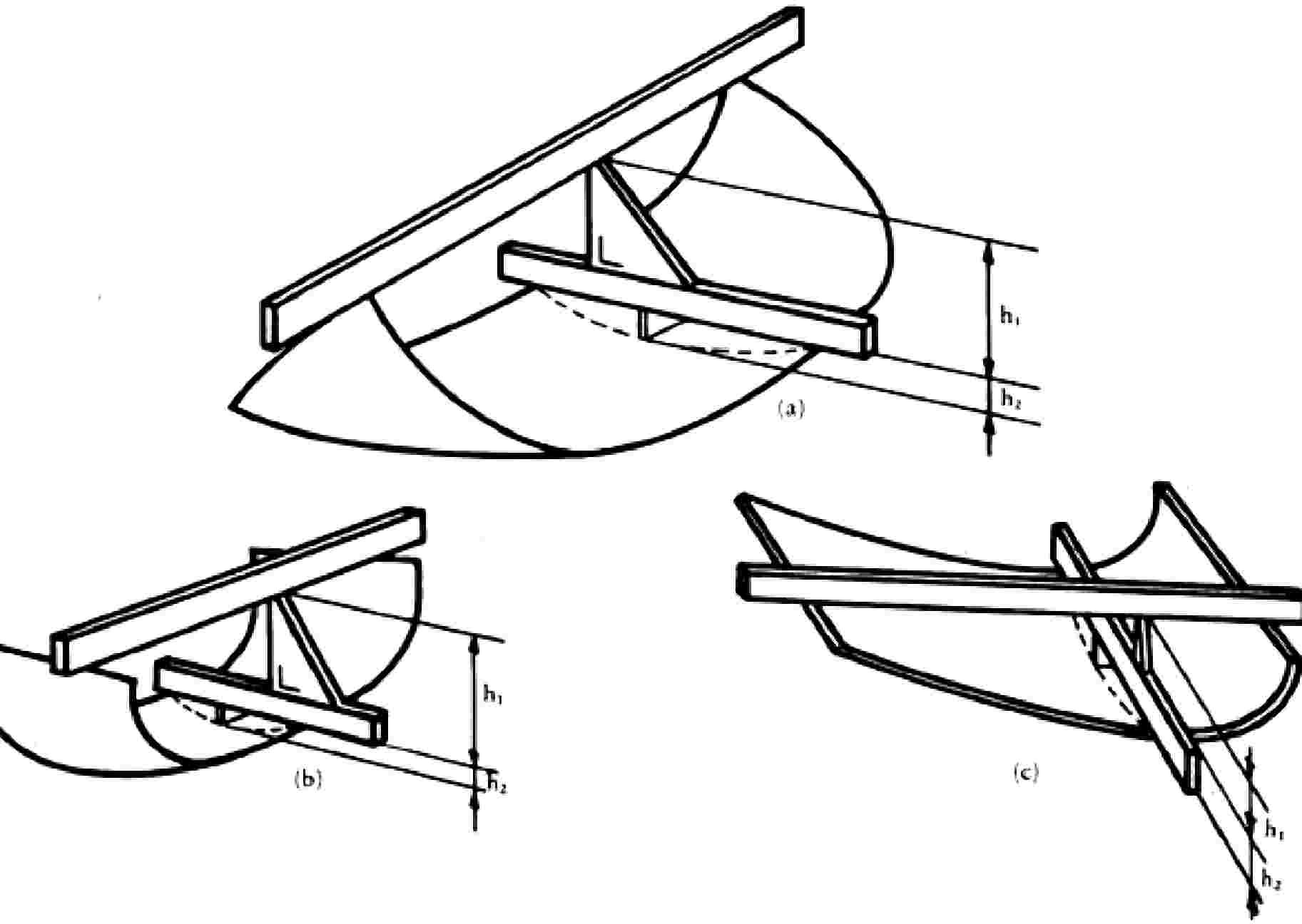
Figure 1 — Determination of height of segment, h
For a glass pane with a single curve, the height of segment will be h1 maximum.
For a glass pane with a double curve, the height of segment will be h1 + h2 maximum.
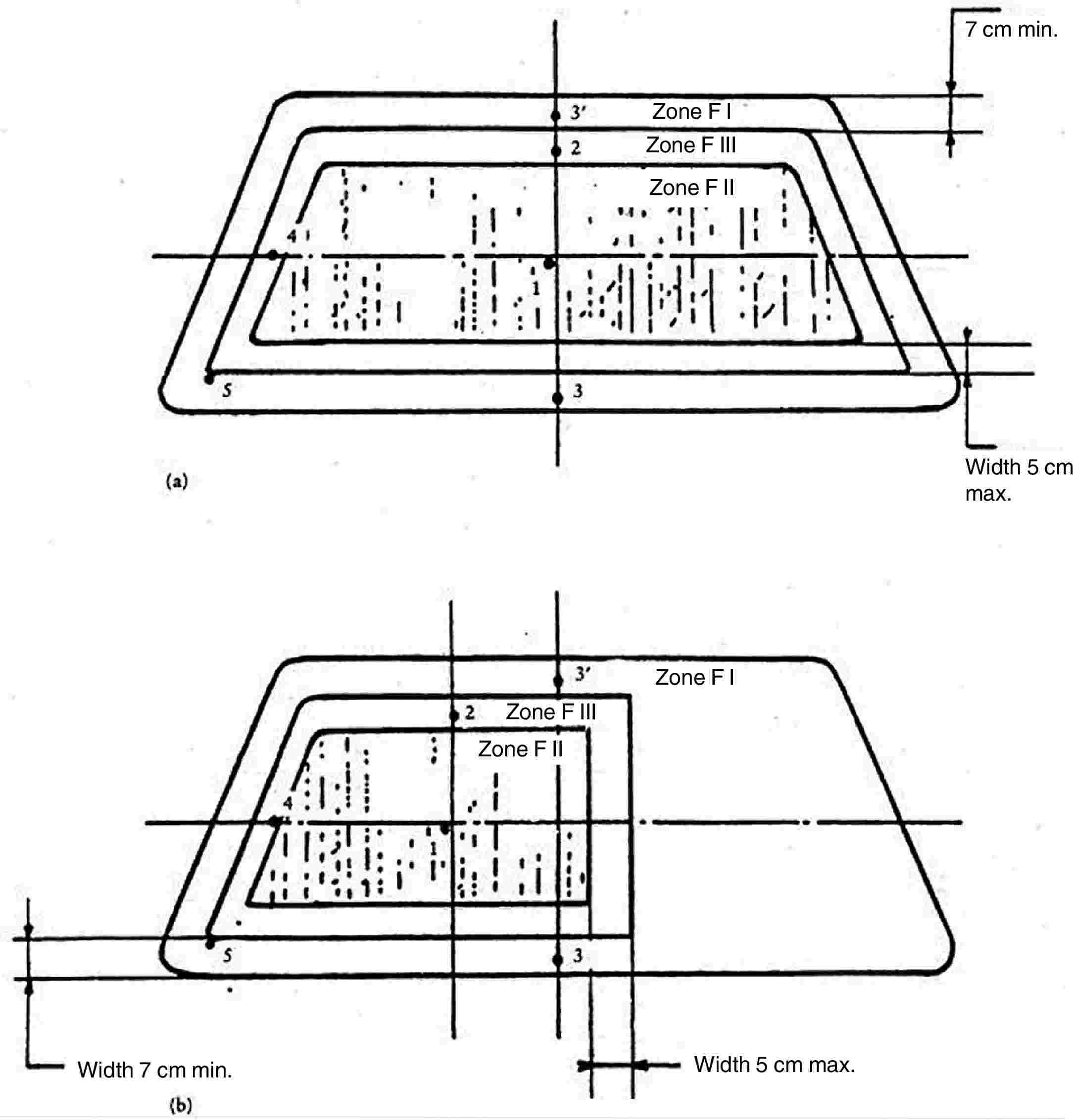
Figure 2 — Prescribed points of impact for windscreens
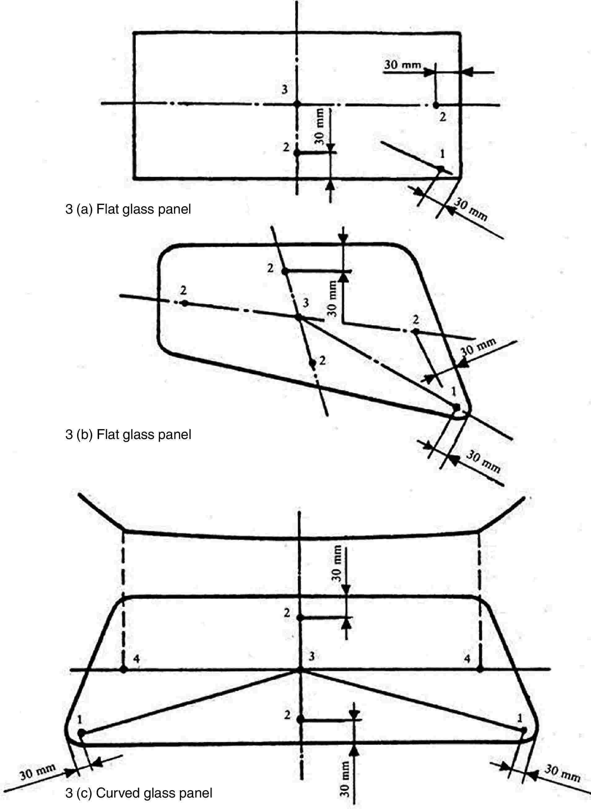
Figures 3 (a), 3 (b) and 3 (c) — Prescribed points of impact for uniformly toughened-glass panes
The points ‘2’ shown in Figures 3 (a), 3 (b) and 3 (c) are examples of the sites for point ‘2’ prescribed in point 2.5 of Annex III E.
ANNEX III O
Checks on conformity of production
1. DEFINITIONS
For the purposes of this Annex:
|
1.1. |
‘type of product’ means all glass panes having the same principal characteristics; |
|
1.2. |
‘thickness class’ means all glass panes having the thickness of component parts within the permitted tolerances; |
|
1.3. |
‘production unit’ means all production facilities of one or several types of glass panes established in the same place; it may include several production lines; |
|
1.4. |
‘shift’ means a period of production carried out by the same production line during daily working hours; |
|
1.5. |
‘production run’ means a continuous period of production of the same type of product in the same shift; |
|
1.6. |
‘Ps’ means the number of glass panes of the same type of product produced by the same shift; |
|
1.7. |
‘Pr’ means the number of glass panes of the same type of product produced during a production run. |
2. TESTS
The glass panes are subjected to the following tests:
2.1. Toughened-glass windscreens
|
2.1.1. |
Fragmentation test in accordance with the requirements of point 2 of Annex III D. |
|
2.1.2. |
Light transmission measurement in accordance with the requirements of point 9.1 of Annex III C. |
|
2.1.3. |
Optical distortion test in accordance with the requirements of point 9.2 of Annex III C. |
|
2.1.4. |
Secondary image separation test in accordance with the requirements of point 9.3 of Annex III C. |
2.2. Uniformly toughened glass panes
|
2.2.1. |
Fragmentation test in accordance with the requirements of point 2 of Annex III E. |
|
2.2.2. |
Light transmission measurement in accordance with the requirements of point 9.1 of Annex III C. |
|
2.2.3. |
In the case of glass panes used as windscreens:
|
2.3. Ordinary laminated-glass windscreens and glass-plastic windscreens
|
2.3.1. |
Headform test in accordance with the requirements of point 3 of Annex III F. |
|
2.3.2. |
2 260-g-ball test in accordance with the requirements of point 4.2 of Annex III F and point 2.2 of Annex III C. |
|
2.3.3. |
Test of resistance to high temperature in accordance with the requirements of point 5 of Annex III C. |
|
2.3.4. |
Light transmission measurement in accordance with the requirements of point 9.1 of Annex III C. |
|
2.3.5. |
Optical distortion test in accordance with the requirements of point 9.2 of Annex III C. |
|
2.3.6. |
Secondary image separation test in accordance with the requirements of point 9.3 of Annex III C. |
|
2.3.7. |
In the case of glass-plastic windscreens only:
|
2.4. Ordinary laminated-glass and glass-plastic panes other than windscreens
|
2.4.1. |
227-g-ball impact test in accordance with the requirements of point 4 of Annex III G. |
|
2.4.2. |
Test of resistance to high temperature in accordance with the requirements of point 5 of Annex III C. |
|
2.4.3. |
Light transmission measurement in accordance with the requirements of point 9.1 of Annex III C. |
|
2.4.4. |
In the case of glass-plastic panes only:
|
|
2.4.5. |
The above provisions are considered to be met if the corresponding tests have been carried out on a windscreen of the same composition. |
2.5. Treated laminated-glass windscreens
|
2.5.1. |
In addition to the tests described in point 2.3, a fragmentation test is to be carried out in accordance with the requirements of point 4 of Annex III H. |
2.6. Glass panes faced with plastic material
In addition to the tests prescribed in the various points of this Annex, the following tests are to be carried out:
|
2.6.1. |
Tests of resistance to abrasion in accordance with the requirements of point 2.1 of Annex III I. |
|
2.6.2. |
Resistance-to-humidity test in accordance with the requirements of point 3 of Annex III I. |
|
2.6.3. |
Test of resistance to chemicals in accordance with the requirements of point 11 of Annex III C. |
2.7. Double-glazed units
The tests to be performed are those specified in this Annex for each glass pane composing the double-glazed unit, with the same frequency and the same requirements.
3. FREQUENCY OF TESTS AND RESULTS
3.1. Fragmentation
3.1.1. Tests
|
3.1.1.1. |
A first series of tests consisting of a break at each impact point specified by this Directive is to be carried out with photographic prints at the beginning of the production of each new type of glass pane to determine the most severe break point. However, for toughened-glass windscreens, this first series of tests is to be carried out only if the annual production of this type of glass pane exceeds 200 units. |
|
3.1.1.2. |
During the production run the check test is to be carried out using the break point as determined in point 3.1.1.1. |
|
3.1.1.3. |
A check is to be carried out at the beginning of each production run or following a change of colour. |
|
3.1.1.4. |
During the production run the check tests are to be carried out at the following minimum frequency:
|
|||||||||||||||
|
3.1.1.5. |
A check test is to be carried out at the end of the production run on one of the last glass panes manufactured. |
|
3.1.1.6. |
for Pr < 20, only one fragmentation test per production run need be carried out. |
3.1.2. Results
All results must be recorded, including the results without photographic print.
In addition, a photographic contact print must be made once per shift, except for Pr ≤ 500. In this last case only one photographic contact print is made per production run.
3.2. Headform impact test
3.2.1. Tests
The check is to be carried out on samples corresponding to at least 0,5 % of the daily production of laminated-glass windscreens of one production line. A maximum of 15 windscreens per day are tested.
The choice of samples must be representative of the production of the various types of windscreen.
With the agreement of the administrative service, these tests may be replaced by the 2 260-g-ball impact test (see point 3.3. below). Behaviour under head impact must in any event be checked on at least two samples for each thickness class per year.
3.2.2. Results
All results must be recorded.
3.3. 2 260-g-ball impact test
3.3.1. Tests
The minimum frequency for the check is one complete test per month for each thickness class.
3.3.2. Results
All results must be recorded.
3.4. 227-g-ball impact test
3.4.1. Tests
The test pieces are to be cut from samples. However, for practical reasons, the tests may be carried out on finished products, or on parts of them.
The check is to be carried out on a sampling corresponding to at least 0,5 % of the production of one shift with a maximum of 10 samples per day.
3.4.2. Results
All results must be recorded.
3.5. High temperature
3.5.1. Tests
The test pieces are to be cut from samples. However, for practical reasons, the tests may be carried out on finished products or on parts of them. These are selected so that all interlayers are tested proportionately to their use.
The check is to be carried out on at least three samples per colour of interlayer taken from the daily production.
3.5.2. Results
All results must be recorded.
3.6. Light transmission
3.6.1. Tests
Representative samples of tinted finished products are to be submitted to this test.
The check is to be carried out at least at the beginning of every production run if there is any change in the characteristics of the glass pane affecting the results of the test.
Glass panes having a regular light transmission measured during component type-approval of not less than 80 % in the case of windscreens and not less than 75 % in the case of glass panes other than windscreens, and glass panes of category V are exempted from this test.
Alternatively, for toughened-glass panes, a certificate of compliance with the above requirements may be submitted by the glass supplier.
3.6.2. Results
The value of light transmission is to be recorded. In addition, for windscreens with shade bands or obscuration bands, it must be verified, from the drawings referred to in point 3.2.1.2.2.3 of Annex III A, that such bands are outside zone I′.
3.7. Optical distortion and secondary-image separation
3.7.1. Tests
Every windscreen is to be inspected for visual defects. In addition, using the methods specified or any method giving similar results, measurements are to be made in the various areas of vision at the following minimum frequencies:
— either where Ps ≤ 200, one sample per shift,
— or where Ps > 200, two samples per shift,
— or 1 % of the whole production, the samples chosen being representative for all production.
3.7.2. Results
All results must be recorded.
3.8. Resistance to abrasion
3.8.1. Tests
Plastic-faced and glass-plastic panes only are to be subjected to this test. There must be at least one check per month and per type of plastic material facing or interlayer.
3.8.2. Results
The measurement of the light scatter is to be recorded.
3.9. Resistance to humidity
3.9.1. Tests
Plastic-faced and glass-plastic panes only are to be subjected to this test. There must be at least one check per month and per type of plastic material facing or interlayer.
3.9.2. Results
All results must be recorded.
3.10. Resistance to chemicals
3.10.1. Tests
Plastic-faced and glass-plastics panes only are to be subjected to this test. There must be at least one check per month and per type of plastic material facing or interlayer.
3.10.2. Results
All results must be recorded.
ANNEX III P
MODEL
Annex to the EC type-approval certificate for a tractor in respect of the windscreen and other glass panes
(Article 4(2) of Directive 2003/37/EC of the European Parliament and of the Council of 26 May 2003 on type-approval of agricultural or forestry tractors, their trailers and interchangeable towed machinery, together with their systems, components and separate technical units)
EC type-approval No: … Extension No: …
|
1. |
Make (name of undertaking) of tractor: … |
|
2. |
Type and where appropriate commercial name of tractor: … |
|
3. |
Name and address of manufacturer: … |
|
4. |
Name and address of manufacturer's authorised representative (if any): … … |
|
5. |
Description of type of windscreen and other glass panes (toughened, laminated, plastic, glass-plastic flat, curved, etc.): … |
|
6. |
EC component type-approval number of the windscreen and other panes: … |
|
7. |
Date on which tractor was submitted for EC type-approval: … |
|
8. |
Technical service responsible for type-approval: … |
|
9. |
Date of report issued by that service: … |
|
10. |
Number of report issued by that service: … |
|
11. |
EC component type-approval for the windscreen and other glass panes is granted/refused ( 32 ): |
|
12. |
Place: … |
|
13. |
Date: … |
|
14. |
Signature: … |
|
15. |
The following documents, bearing the EC type-approval number given above, are attached to this document: … dimensioned drawings; … sketch or photograph of the windscreen and other glass panes in the tractor cab. These data must be supplied to the competent authorities of the other Member States at their specific request. |
|
16. |
Remarks: … … … … … |
ANNEX IV
Mechanical couplings between tractor and towed vehicle and vertical load on the coupling point
1. DEFINITIONS
|
‘1.1. |
Mechanical coupling between tractor and towed vehicle’ means the components installed on the tractor and on the towed vehicle in order to provide the mechanical coupling between those vehicles. Only mechanical coupling components for tractors are covered in this Directive. Among the various types of mechanical coupling components for tractors a basic distinction is made between: — clevis type (see Figures 1 and 2 of Appendix 1), — no-swivel clevis couplings (see Figure 1d of Appendix 1), — towing hook (see Figure 1 – ‘Hitch-hook dimensions’ in ISO 6489-1:2001), — tractor drawbar (see Figure 3 of Appendix 1), — ball type (see Figure 4 of Appendix 1), — pin (piton) type (see Figure 5 of Appendix 1). |
|
1.2. |
‘Type of mechanical coupling between tractor and towed vehicle’ means parts which do not differ from one another in such essential respects as:
|
|
1.3. |
‘Reference centre of mechanical coupling’ means the point on the pin axis which is equidistant from the wings in the case of a fork and the point resulting from the intersection of the plane of symmetry of the hook with the generatrix of the concave part of the hook at the level of contact with the ring when this is in the traction position. |
|
1.4. |
‘Height above ground of mechanical coupling (h)’ means the distance between the horizontal plane through the reference centre of the mechanical coupling and the horizontal plane on which the wheels of the tractor are resting. |
|
1.5. |
‘Projection of mechanical coupling (c)’ means the distance between the reference centre of the mechanical coupling component and the vertical plane passing through the axle on which the rear wheels of the tractor are mounted. |
|
1.6. |
‘Vertical load on the coupling point (S)’ means the load transmitted, under static conditions on the reference centre of the mechanical coupling. |
|
1.7. |
‘Automatic’ means a mechanical coupling component which closes and secures itself when the sliding mechanism for the drawbar rings is actuated, without further action. |
|
1.8. |
‘Wheelbase of tractor (l)’ means the distance between the vertical planes perpendicular to the median longitudinal plane of the tractor passing through the axles of the tractor. |
|
1.9. |
‘Weight on the front axle of the unladen tractor (ma)’ means that part of the weight of the tractor which, under static conditions, is transmitted on the ground by the front axle of the tractor. |
2. GENERAL REQUIREMENTS
|
2.1. |
The mechanical coupling components may be designed to function automatically or non-automatically. |
|
2.2. |
The mechanical coupling components on the tractor must conform to the dimensional and strength requirements in point 3.1 and point 3.2 and the requirements for the vertical load on the coupling point in point 3.3. |
|
2.3. |
The mechanical coupling components must be so designed and made that in normal use they will continue to function satisfactorily and retain the characteristics prescribed by this Directive. |
|
2.4. |
All parts of mechanical coupling components must be made of materials of a quality sufficient to withstand the tests referred to in point 3.2. and must have durable strength characteristics. |
|
2.5. |
All the couplings and their locks must be easy to engage and release and must be so designed that under normal operating conditions no accidental de-coupling is possible. In automatic coupling components the locked position must be secured in a form-locking manner by two independently functioning safety devices. However, the latter may be released using the same control device. |
|
2.6. |
The drawbar ring must be capable of tilting horizontally at least 60° on both sides of the longitudinal axis of a non-built-in coupling device. In addition, vertical mobility of 20° upwards and downwards is required at all times. (See also Appendix 1.) The angles of articulation must not be attained at the same time. |
|
2.7. |
The jaw must permit the drawbar rings to swivel axially at least 90° to the right or left around the longitudinal axis of the coupling with a fixed braking momentum of between 30 and 150 Nm. The towing hook, no-swivel clevis coupling, ball type coupling and pin type coupling must allow the drawbar ring to swivel axially at least 20° to the right or left around the longitudinal axis of the coupling. |
|
2.8. |
Provided at least one mechanical coupling has received EC component type-approval, other types of mechanical link or coupling used in the Member States shall be authorised for a period of 10 years dating from the entry into force of Directive 89/173/EEC without invalidating the EC type-approval of the tractor, on condition that the mounting thereof does not affect the partial approvals. |
|
2.9. |
In order to prevent unintentional uncoupling from the hitch ring, the distance between the towing hook tip and the keeper (clamping device) shall not exceed 10 mm at the maximum design load. |
3. SPECIAL REQUIREMENTS
3.1. Dimensions
The dimensions of the mechanical coupling components on the tractor must comply with Appendix 1, Figures 1 to 5 and Table 1.
3.2. Strength
|
3.2.1. |
For the purposes of checking their strength the mechanical coupling components must undergo a dynamic test under the conditions set out in Appendix 2 or a static test under the conditions set out in Appendix 3. |
|
3.2.2. |
The test must not cause any permanent deformation, breaks or tears. |
3.3. Vertical load on the coupling point (S)
|
3.3.1. |
The maximum static vertical load is laid down by the manufacturer. However, it must not exceed 3 000 kg, except for the ball type coupling, where the maximum value shall not exceed 4 000 kg. |
|
3.3.2. |
Conditions of acceptance:
|
3.4. Height above the ground of the coupling device (h)
(see figure below).
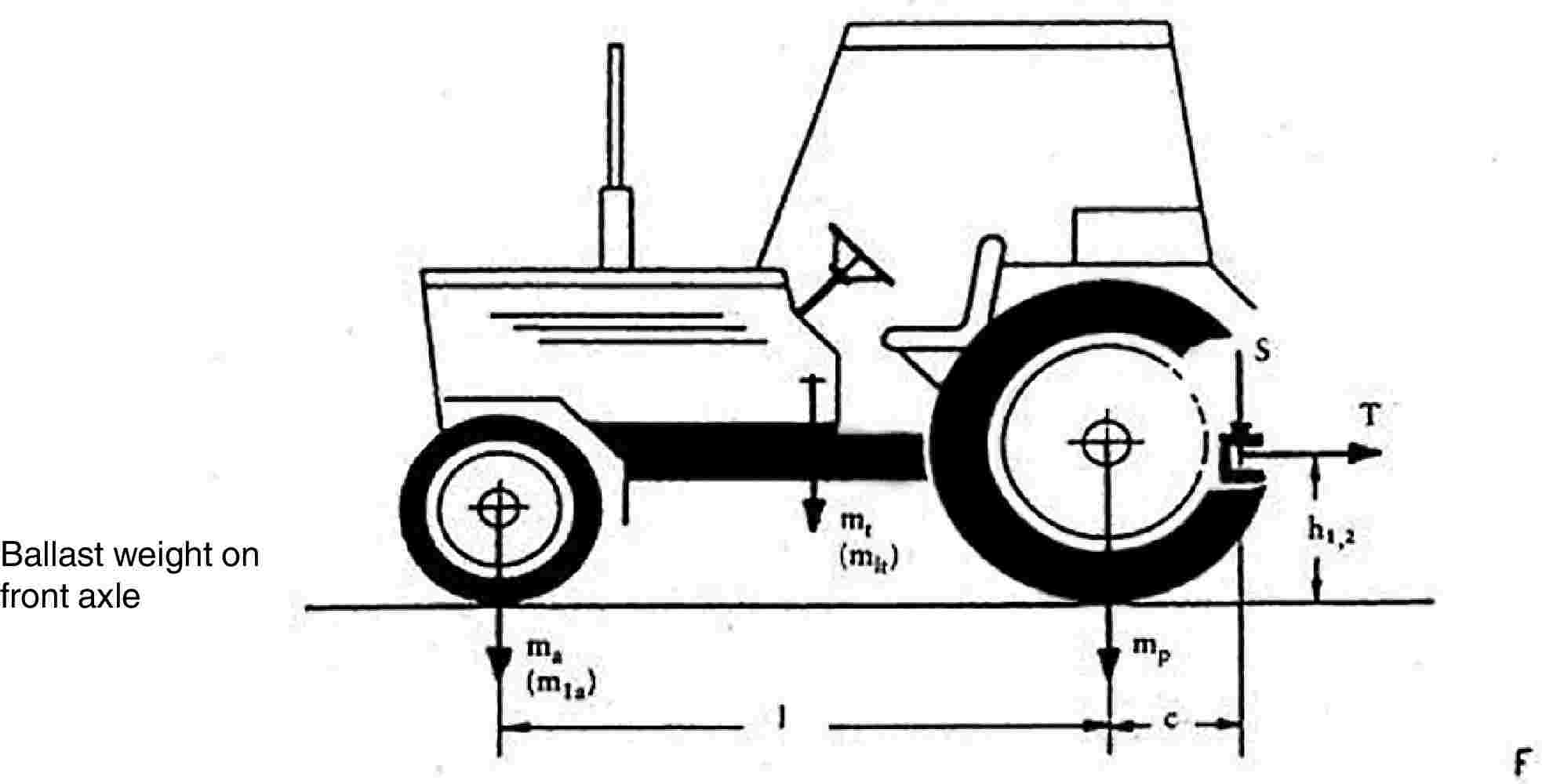
|
3.4.1. |
All tractors with a loaded mass exceeding 2,5 tonnes must be fitted with a trailer coupling having a ground clearance satisfying one of the following relations:
or
where:
Masses mt, mlt, ma and mla are expressed in kg. |
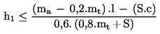
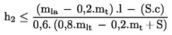
4. APPLICATION FOR EC COMPONENT TYPE-APPROVAL
|
4.1. |
An application for EC component type-approval for a tractor with respect to the coupling device must be submitted by the manufacturer of the device or by his authorised representative. |
|
4.2. |
For each type of mechanical coupling component the application must be accompanied by the following documents and particulars: — scale drawings of the coupling device (three copies). These drawings must in particular show the required dimensions in detail as well as the measurements for mounting the device, — a short technical description of the coupling device specifying the type of construction and the material used, — a statement of the value of D as referred to in Appendix 2 for the dynamic test or the value of T (towable mass in tonnes), corresponding to 1,5 times the technically permissible maximum laden trailer mass, as referred to in Appendix 3 for the static test, and also the vertical maximum load on the coupling point S (expressed in kg), — one or more sample devices as required by the technical service. |
5. INSCRIPTIONS
|
5.1. |
Every mechanical coupling component conforming to the type for which EC component type-approval has been granted must bear the following inscriptions:
|
|
5.2. |
The data must be clearly visible, easily legible and durable. |
6. INSTRUCTIONS FOR USE
All mechanical couplings must be accompanied by the manufacturer’s instructions for use. These instructions must include the EC component type-approved number and also the values of D (kN) or T (tonnes) depending on which test was performed on the coupling.
Appendix 1
DRAWINGS OF MECHANICAL COUPLING COMPONENTS
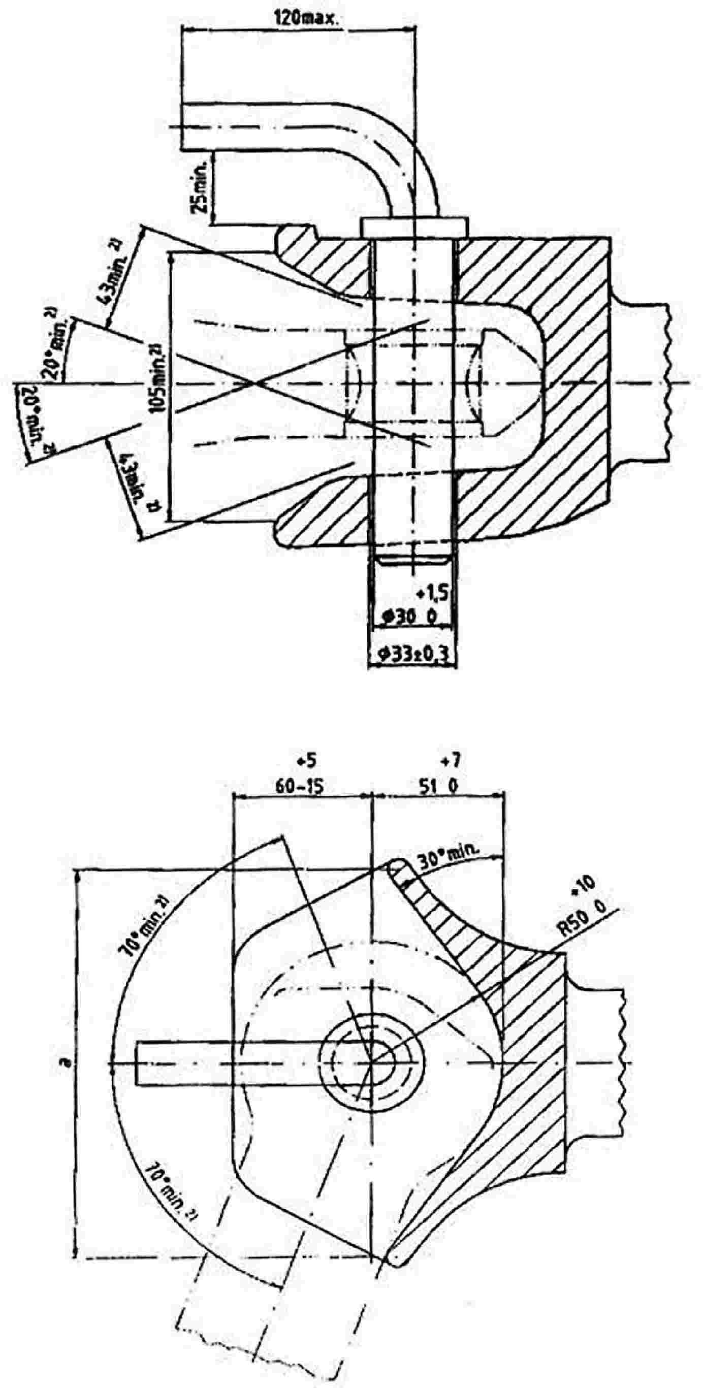
Figure 1a — Non-automatic trailer coupling, with cylindrical locking pin
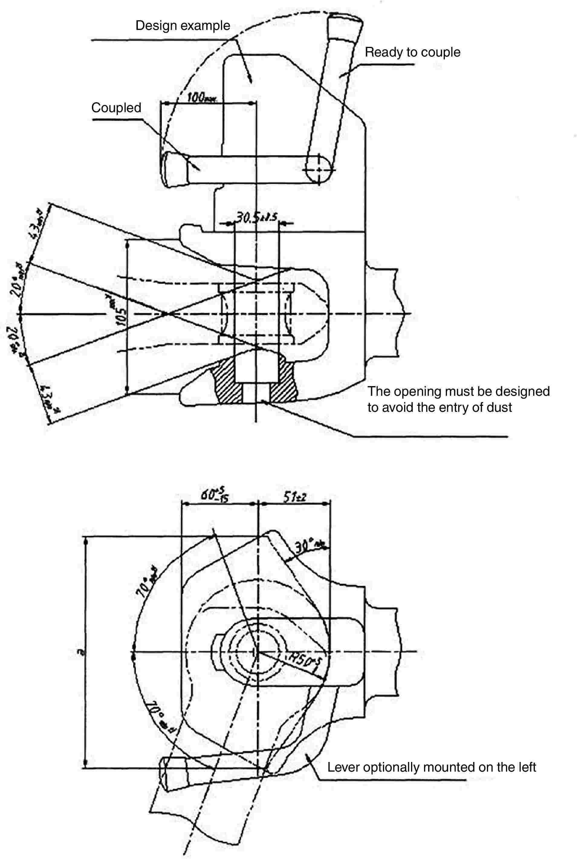
Figure 1b — Automatic trailer coupling, with cylindrical locking pin
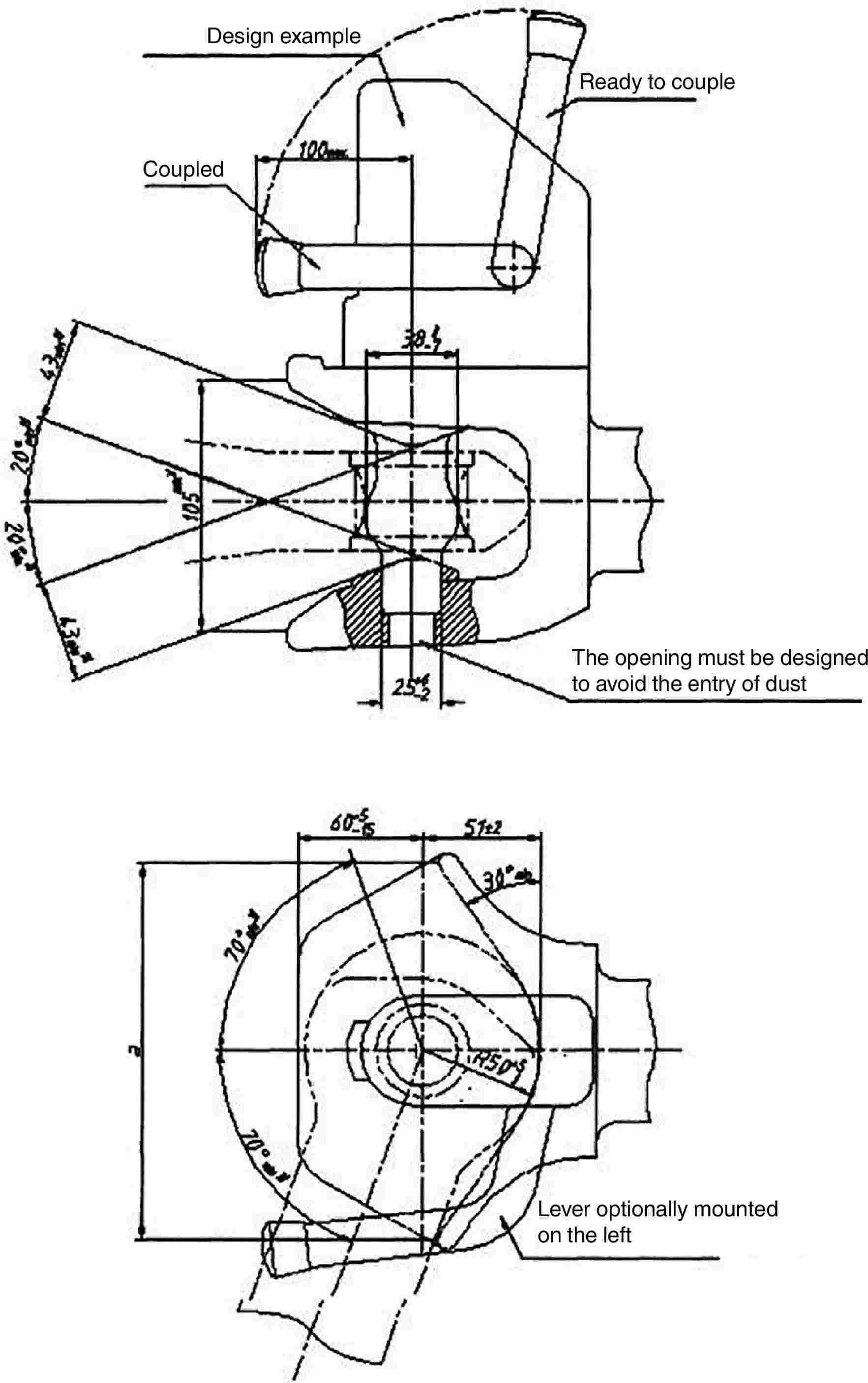
Figure 1c — Automatic trailer coupling, with cambered locking pin
Figure 1d
No-swivel clevis coupling (corresponding to ISO 6489-5:2011)
|
|
|
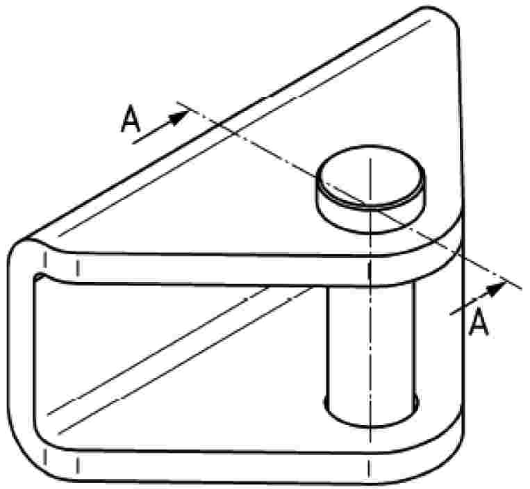
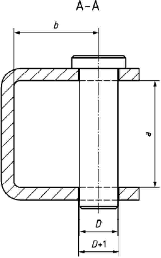
Table 1
Shapes and dimensions of trailer or implement clevis couplings
|
Vertical load S kg |
D value D kN |
Shape |
Dimension mm |
||
|
D ± 0,5 |
a min. |
b min. |
|||
|
≤ 1 000 |
≤ 35 |
w |
18 |
50 |
40 |
|
≤ 2 000 |
≤ 90 |
x |
28 |
70 |
55 |
|
≤ 3 000 |
≤ 120 |
y |
43 |
100 |
80 |
|
≤ 3 000 |
≤ 120 |
z |
50 |
110 |
95 |
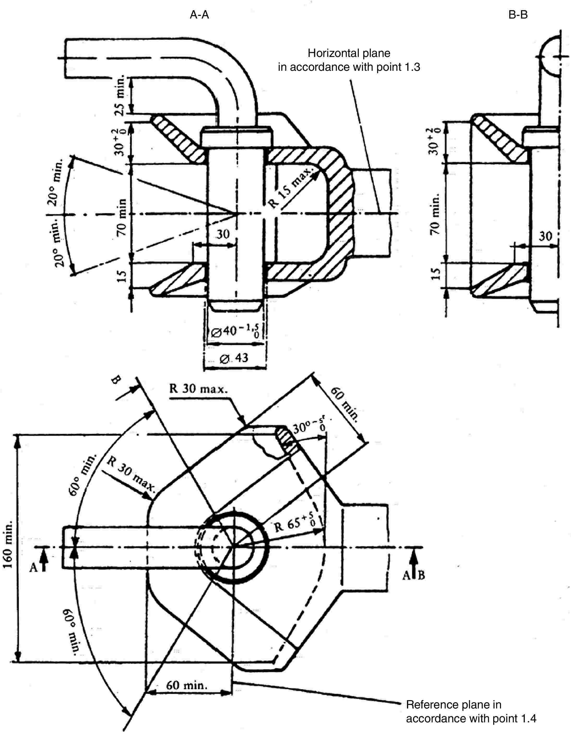
Figure 2 — Non-automatic trailer coupling
corresponds to ISO 6489 Part 2 of July 2002
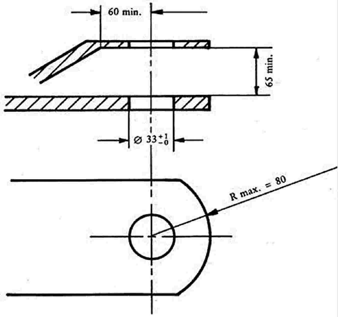
Figure 3 — Tractor drawbar
corresponds ISO Standard 6489 Part 3 of June 2004
Figure 4
Ball type coupling (corresponding to ISO 24347:2005)
|
|
|
|
|
|
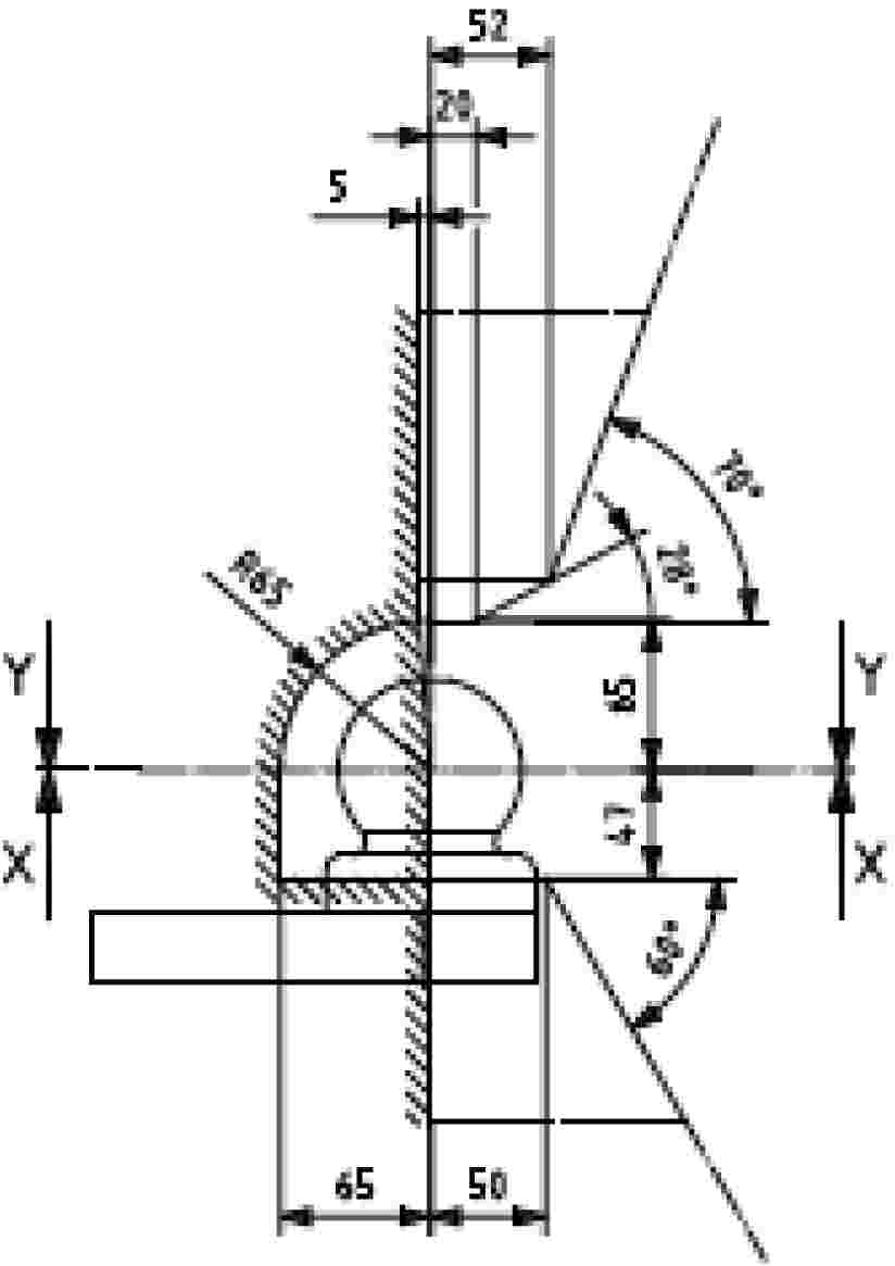
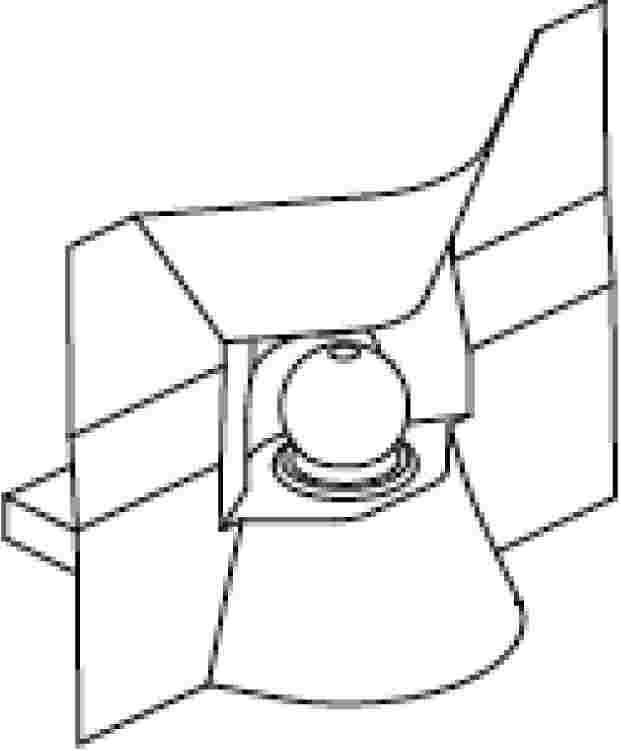
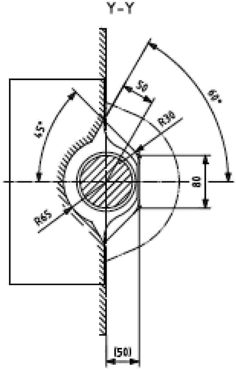
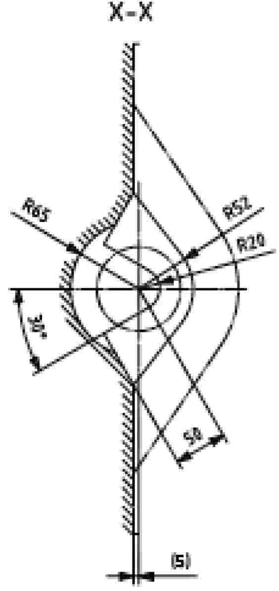
Figure 5
Pin type coupling (corresponding to ISO 6489-4:2004)
|
|
|
|
|
|
|
|
|
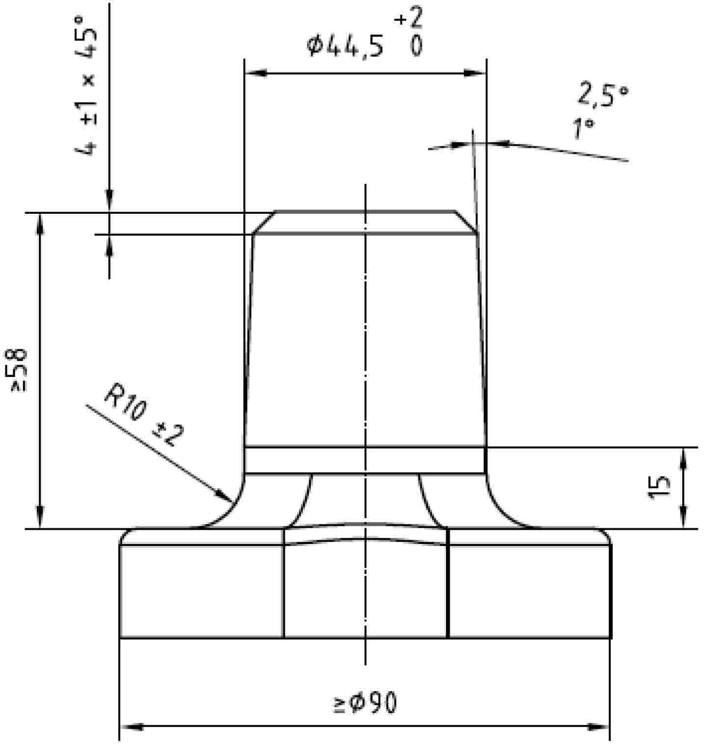
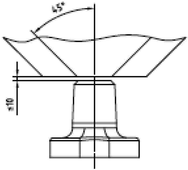
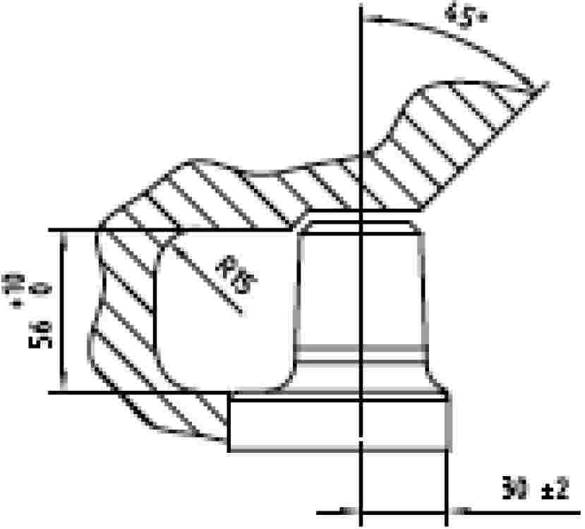
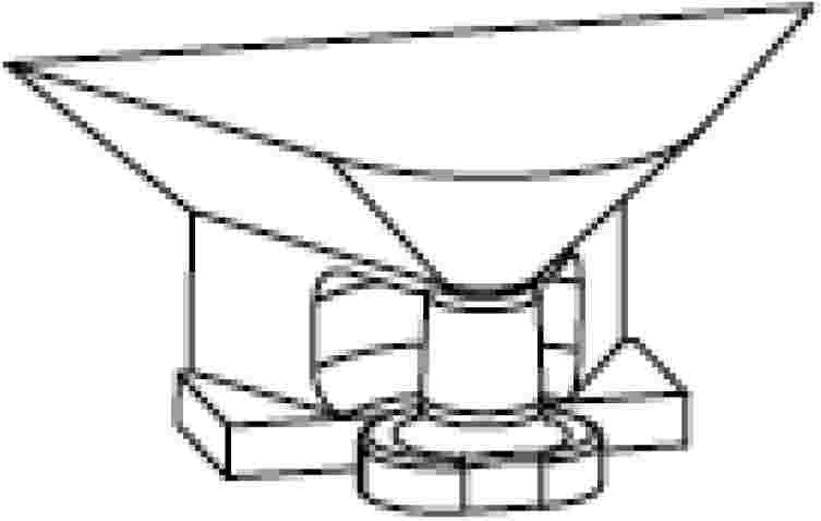
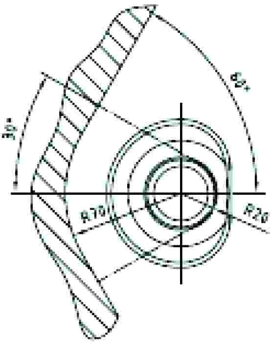
Appendix 2
DYNAMIC TEST METHOD
1. TEST PROCEDURE
The strength of the mechanical coupling is to be established by alternating traction on a test bed.
This method describes the fatigue test to be used on the complete mechanical coupling device, i.e. when fitted with all the parts needed for its installation the mechanical coupling is mounted and tested on a test bed.
The alternating forces are applied as far as possible sinusoidally (alternating and/or rising) with a load cycle depending on the material involved. No tears or breaks may occur during the test.
2. TEST CRITERIA
The horizontal force components in the longitudinal axis of the vehicle together with the vertical force components form the basis of the test loads.
In so far as they are of secondary importance, horizontal force components at right angles to the longitudinal axis of the vehicle and also moments are not to be taken into consideration.
The horizontal force components in the longitudinal axis of the vehicle are represented by a mathematically established representative force, the value D.
The following equation is applied to the mechanical coupling:
D = g · (MT · MR)/(MT + MR)
Where:
|
MT |
= |
the technically permissible total mass of the tractor, |
|
MR |
= |
the technically permissible total mass of the towed vehicles, |
|
g |
= |
9,81 m/s2. |
The vertical force components at right angles to the track are expressed by the static vertical load S (kg).
The technically permissible masses MT and MR are given by the manufacturer in tonnes.
3. TEST PROCEDURE
3.1. General requirements
The test force is applied to the mechanical coupling device being tested by means of an appropriate standard drawbar ring beneath an angle formed by the position of the vertical test load Fv vis-à-vis the horizontal test load Fh in the direction of the median longitudinal plane passing from top front to bottom rear.
The test force is applied at the usual point of contact between the mechanical coupling device and the drawbar ring.
The play between the coupling device and the ring must be kept to a minimum.
In principle the test force is applied in an alternating manner around the zero point. With an alternating test force the resulting load is equal to zero.
Should the design of the coupling device (e.g. excessive play, towing hook) make it impossible to carry out the test with an alternating test load, the test load may also be applied on a rising basis in the direction of traction or pressure, whichever is the greater.
Where the test is carried out with a rising force curve, the test load is equal to the upper (highest) load, and the lower (smallest) load should not exceed 5 % of the upper load.
Care should be taken in the alternating force test to ensure that by suitable mounting of the test apparatus and choice of power conduction system no additional moments or forces arising at right angles to the test force are introduced; the angular error for the direction of force in the alternating force test should not exceed ± 1,5°; and for the rising force test the angle is set in the upper load position.
The test frequency must not exceed 30 Hz.
For components made of steel or steel casting the load cycle amounts to 2 · 106. The subsequent tear test is carried out using the colour penetration method or similar method.
If springs and/or dampers are incorporated into the coupling parts, they are not to be removed during the test but may be replaced if, during the test, they are subject to strain under conditions which would not obtain during normal operation (e.g. heat action) and become damaged. Their behaviour before, during and after the test must be described in the test report.
3.2. Test forces
The test force consists in geometrical terms of the horizontal and vertical test components as follows:
![]()
where:
![]()
in the case of alternating force,
or
![]()
in the case of rising force (traction or pressure),
![]()
(value expressed in kN)
|
S |
= |
static drawbar load (load on the track, expressed in kg). |
Appendix 3
COUPLING DEVICE
STATIC TEST METHOD
1. TEST SPECIFICATIONS
1.1. General
|
1.1.1. |
Subject to a check on its construction characteristics, the towing device must undergo static tests in accordance with the requirements of points 1.2, 1.3 and 1.4. |
1.2. Test preparation
The tests must be carried out on a special machine, with the towing device and any structure coupling it to the body of the tractor attached to a rigid structure by means of the same components used to mount it on the tractor.
1.3. Test instruments
The instruments used to record loads applied and movements must have the following degree of accuracy:
— loads applied ± 50 daN,
— movements ± 0,01 mm.
1.4. Test procedure
|
1.4.1. |
The coupling device must first be subjected to a pre-traction load which does not exceed 15 % of the traction test load defined in point 1.4.2.
|
|
1.4.2. |
The data recorded for plotting the load/deformation curve under traction, or the graph of that curve provided by the printer linked to the traction machine, must be based on the application of increasing loads only, starting from 500 daN, in relation to the reference centre of the coupling device. There must be no breaks for values up to and including the traction test load which is established as 1,5 times the technically permissible trailer mass; in addition, the load/deformation curve must show a smooth progression, without irregularities, in the interval between 500 daN and 1/3 of the maximum traction load.
|
|
1.5. |
The test referred to in point 1.4.2 must be preceded by a test in which an initial load of three times the maximum permissible vertical force (in daN, equal to g · S/10) recommended by the manufacturer is applied in a gradually increasing manner, starting from an initial load of 500 daN, to the reference centre of the coupling device. During the test, deformation of the coupling device must not exceed 10 % of the maximum elastic deformation occurring. The check is carried out after removing the vertical force (in daN, equal to g · S/10) and returning to the initial load of 500 daN. |
Appendix 4
COMPONENT TYPE-APPROVAL MARK
The EC component type-approval mark consists of:
— a rectangle surrounding the lower-case letter ‘e’ followed by the distinguishing code (letter(s) or number) of the Member State which has granted the component type-approval:
— 1 for Germany; 2 for France; 3 for Italy; 4 for the Netherlands; 5 for Sweden; 6 for Belgium; 7 for Hungary; 8 for the Czech Republic; 9 for Spain; 11 for the United Kingdom; 12 for Austria; 13 for Luxembourg; 17 for Finland; 18 for Denmark; 19 for Romania; 20 for Poland; 21 for Portugal; 23 for Greece; 24 for Ireland; 26 for Slovenia; 27 for Slovakia; 29 for Estonia; 32 for Latvia; 34 for Bulgaria; 36 for Lithuania; 49 for Cyprus and 50 for Malta,
— an EC component type-approval number, which corresponds to the number of the EC component type-approval certificate issued for the type of coupling device in question as regards its strength and dimensions, placed in any convenient position near the rectangle,
— by the capital letter ‘D’ or ‘S’ according to which test was performed on the mechanical coupling (dynamic test = D and static test = S) above the rectangle surrounding the lower-case letter ‘e’.
Example of an EC component type-approval mark
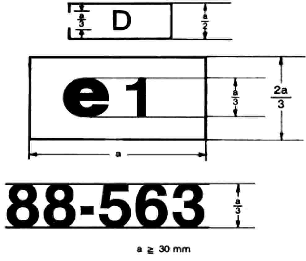
The coupling bearing the EC component type-approval mark shown above is a device for which EC component type-approval was granted in Germany (e 1) under the number 88-563 and on which a dynamic strength test (D) was performed.
Example of an EC type-approval mark
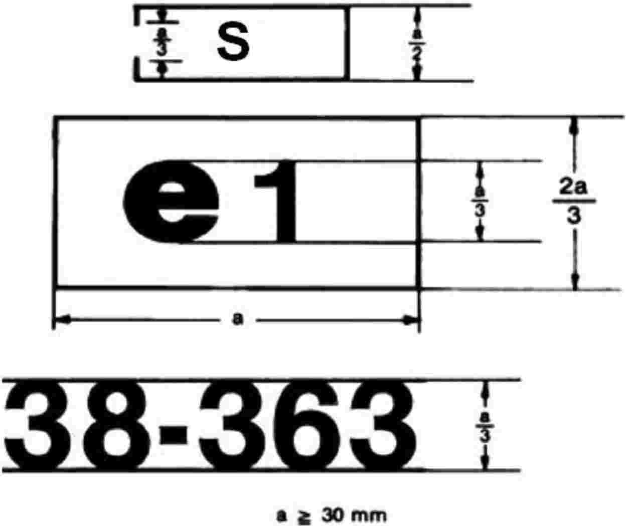
The coupling bearing the EC component type-approval mark shown above is a device for which EC component type-approval was granted in Germany (e1) under the number 38-363 and on which a static strength test (S) was performed.
Appendix 5
MODEL EC COMPONENT TYPE-APPROVAL CERTIFICATE
NOTIFICATION CONCERNING THE GRANTING, REFUSAL, WITHDRAWAL OR EXTENSION OF EC COMPONENT TYPE-APPROVAL WITH REGARD TO THE STRENGTH AND DIMENSIONS AND VERTICAL LOAD ON THE COUPLING POINT OF A TYPE OF COUPLING DEVICE (CLEVIS TYPE, NO-SWIVEL CLEVIS COUPLINGS, TOWING HOOK, TRACTOR DRAWBAR, BALL TYPE AND PIN TYPE.)
EC component type-approval No:
…
… extension ( 34 )
|
1. |
Trade name or mark: … … |
|
2. |
Type of coupling device (clevis type, no-swivel clevis couplings, towing hook, tractor drawbar, ball type, pin type) ( 35 ) … |
|
3. |
Name and address of manufacturer of coupling device: … … |
|
4. |
If applicable, name and address of authorised representative of manufacturer of coupling device: … |
|
5. |
The coupling device was subjected to a dynamic/static (35) test and approved for the following values:
|
|
6. |
Submitted for EC component type-approval on: … |
|
7. |
Technical service responsible for carrying out the tests: … |
|
8. |
Date and number of test report: … |
|
9. |
EC component type-approval in respect of the mechanical coupling is granted/refused (35) : … |
|
10. |
Place: … |
|
11. |
Date: … |
|
12. |
The following documents, bearing the component type-approval number shown above, are attached to this certificate (e.g. test report, drawings, etc.). This information is to be made available to the competent services of the other Member States only by express request: … … |
|
13. |
Remarks: … |
|
14. |
Signature: … |
Appendix 6
CONDITIONS FOR GRANTING EC TYPE-APPROVAL
|
1. |
The application for EC type-approval of a tractor, with regard to the strength and dimensions of a coupling device, is submitted by the tractor manufacturer or by his authorised representative. |
|
2. |
A tractor representative of the tractor type to be approved, on which a coupling device, duly approved, is mounted is submitted to the technical services responsible for conducting the type-approval tests. |
|
3. |
The technical service responsible for conducting the type-approval tests checks whether the approved type of coupling device is suitable for mounting on the type of tractor for which type-approval is requested. In particular, it ascertains that the attachment of the coupling device corresponds to that which was tested when the EC component type-approval was granted. |
|
4. |
The holder of the EC type-approval may ask for its extension for other types of coupling device. |
|
5. |
The competent authorities grant such extension on the following conditions:
|
|
6. |
A certificate, of which a model is shown in Appendix 5, is annexed to the EC type-approval certificate for each type-approval or type-approval extension which has been granted or refused. |
|
7. |
If the application for EC type-approval for a type of tractor is made at the same time as the request for EC component type-approval for a type of coupling device on a tractor for which EC type-approval is requested, then points 2 and 3 are unnecessary. |
Appendix 7
MODEL
ANNEX TO THE EC TYPE-APPROVAL CERTIFICATE FOR A TRACTOR TYPE WITH REGARD TO THE COUPLING DEVICE AND THE STRENGTH OF ITS ATTACHMENT TO THE TRACTOR
(Article 4(2) of Directive 2003/37/EC of the European Parliament and of the Council of 26 May 2003 on type-approval of agricultural or forestry tractors, their trailers and interchangeable towed machinery, together with their systems, components and separate technical units)
EC type-approval No: …
… extension ( 36 )
|
1. |
Trade name or mark of tractor: … |
|
2. |
Tractor type and trade name: … |
|
3. |
Name and address of tractor manufacturer: … … |
|
4. |
If applicable, name and address of manufacturer's authorised representative: … … |
|
5. |
Trade name or mark of coupling device: … … |
|
6. |
Type(s) of coupling device(s): … |
|
7. |
EC mark and EC component type-approval number: … |
|
8. |
Extension of EC type-approval to the following type(s) of coupling: … … |
|
9. |
Permissible static vertical load on the coupling point: … (kg) |
|
10. |
Tractor submitted for EC type-approval testing on: … |
|
11. |
Technical service responsible for EC type-approval tests: … |
|
12. |
Date of test report issued by that technical service: … |
|
13. |
Number of test report issued by that service: … |
|
14. |
EC type-approval with regard to the coupling device and the strength of its attachment to the tractor has been granted/refused ( 37 ). |
|
15. |
The extension of the EC type-approval with regard to the coupling device and the strength of its attachment to the tractor has been granted/refused (37) : … |
|
16. |
Place: … |
|
17. |
Date: … |
|
18. |
Signature: … |
ANNEX V
Location and method of affixing statutory plates and inscriptions on the body of the tractor
1. GENERAL
|
1.1. |
All agricultural or forestry tractors must be provided with the plate and inscriptions described in the following points. The plate and inscriptions are attached either by the manufacturer or by his authorised representative. |
2. MANUFACTURER'S PLATE
|
2.1. |
A manufacturer's plate, modelled on that shown in the Appendix hereto, must be firmly attached in a conspicuous and readily accessible position on a part normally not subject to replacement in use. It must show clearly and indelibly the following information in the order listed.
|
|
2.2. |
The manufacturer may give additional information below or to the side of the prescribed inscriptions, outside a clearly marked rectangle enclosing only the information prescribed in points 2.1.1 to 2.1.7 (see example of manufacturer's plate). |
3. TRACTOR IDENTIFICATION NUMBER
The tractor identification number is a fixed combination of characters assigned to each tractor by the manufacturer. Its purpose is to ensure that every tractor, and in particular its type, can be clearly identified over a period of 30 years through the intermediary of the manufacturer, without a need for further reference.
The identification number shall comply with the following requirements:
|
3.1. |
It must be marked on the manufacturer's plate, and also on the chassis, or other similar structure.
|
4. CHARACTERS
|
4.1. |
Roman letters and arabic numerals must be used for all of the markings provided for in points 2 and 3. However, the roman letters used in the markings provided for in points 2.1.1 and 3 must be capital letters. |
|
4.2. |
For the tractor identification number:
|
Appendix
MODEL
Annex to the EC type-approval certificate for a tractor type with regard to the position and the method of affixing statutory plates and inscriptions on the body of the tractor
(Article 4(2) of Directive 2003/37/EC of the European Parliament and of the Council of 26 May 2003 on type-approval of agricultural or forestry tractors, their trailers and interchangeable towed machinery, together with their systems, components and separate technical units)
EC type-approval number: …
|
1. |
Make of tractor or business name of manufacturer: … |
|
2. |
Type and, if appropriate, trade name of tractor: … |
|
3. |
Manufacturer's name and address: … |
|
4. |
If applicable, name and address of manufacturer's authorised representative: … |
|
5. |
Date of submission of tractor for EC type-approval: … |
|
6. |
Technical service conducting the type-approval tests: … |
|
7. |
Date of report issued by that service: … |
|
8. |
Number of report issued by that service: … |
|
9. |
EC type-approval for the location and method of affixing statutory plates and inscriptions on the body of the tractor is granted/refused ( 38 ). |
|
10. |
Place: … |
|
11. |
Date: … |
|
12. |
Signature: … |
|
13. |
The following documents bearing the EC type-approval number indicated above are attached to this certificate: … dimensioned drawings; … sketch or photograph of the location and method of affixing statutory plates and inscriptions on the body of the tractor. The data must be supplied to the competent authorities of the other Member States if they so request. |
|
14. |
Remarks: … … … … |
ANNEX VI
BRAKE CONTROL OF TOWED VEHICLES AND BRAKE COUPLING BETWEEN THE TRACTOR AND TOWED VEHICLES
|
1. |
Where a tractor includes a trailer brake control, the control must be either hand- or foot-operated and it must be possible to moderate and operate it from the driver's seat, but it must not be affected by any operation of other controls. Where the tractor is fitted with a pneumatic or hydraulic coupling system located between the tractor and the towed mass, only one single control should be fitted for the service braking of the vehicle combination. |
|
2. |
The braking systems used may be systems the characteristics of which are as defined in Annex I to Directive 76/432/EEC relating to the braking devices of wheeled agricultural or forestry tractors. The fitting must be designed and effected in such a way as to ensure that the operation of the tractor is not adversely affected in the event of the failure or the poor operation of the towed vehicle's breaking device or in the case of a breach in the coupling. |
|
3. |
Where the coupling between the tractor and the towed vehicle(s) is hydraulic or pneumatic it must also comply with one or other of the following conditions. 3.1. Hydraulic coupling: The hydraulic coupling must be of a single conduit type. It must comply with standard ISO 5676 of 1983, the projecting section being on the tractor. Operation of the control must permit zero pressure to be delivered to the coupling head in the rest position; the working pressure must be no less than 10 and no more that 15 MPa. It must not be possible to disconnect the source of power from the engine. 3.2. Pneumatic coupling: The coupling between the tractor and the towed vehicle(s) of a dual-conduit type: an automatic conduit and a direct braking conduit operates by an increase in pressure. The coupling head must comply with standard ISO 1728 of 1980. Operation of the control must permit a working pressure of no less than 0,65 and no more than 0,8 MPa to be delivered to the coupling head. |
Appendix
MODEL
ANNEX TO THE EC TYPE-APPROVAL CERTIFICATE FOR A TRACTOR TYPE WITH REGARD TO THE BRAKE CONTROL OF THE TOWED VEHICLE
(Article 4(2) of Directive 2003/37/EC of the European Parliament and of the Council of 26 May 2003 on type-approval of agricultural or forestry tractors, their trailers and interchangeable towed machinery, together with their systems, components and separate technical units)
EC type-approval No: …
|
1. |
Make of tractor (or business name of manufacturer): … … |
|
2. |
Type and where appropriate commercial name of tractor: … |
|
3. |
Manufacturer's name and address: … |
|
4. |
If applicable, name and address of manufacturer's authorised representative: … |
|
5. |
Description of component(s) and/or characteristic(s) of the brake control of the towed vehicle: … |
|
6. |
Date of submission of tractor for EC type-approval: … |
|
7. |
Technical service conducting the type-approval tests: … |
|
8. |
Date of report issued by that service: … |
|
9. |
Number of report issued by that service: … |
|
10. |
EC type-approval for the brake control of the towed vehicle is granted/refused ( 39 ): |
|
11. |
Place: … |
|
12. |
Date: … |
|
13. |
Signature: … |
|
14. |
The following documents bearing the EC type-approval number indicated above are attached to this certificate: … sketch or photograph of the relevant parts of the tractor. These data must be supplied to the competent authorities of the other Member States if they so request. |
|
15. |
Remarks: … … |
ANNEX VII
PART A
Repealed Directive with list of its successive amendments
(referred to in Article 10)
|
Council Directive 89/173/EEC (OJ L 67, 10.3.1989, p. 1) |
|
|
1994 Act of Accession, Annex I, Point XI.C.II.7 (OJ C 241, 29.8.1994, p. 207) |
|
|
Directive 97/54/EC of the European Parliament and of the Council (OJ L 277, 10.10.1997, p. 24) |
only as regards the reference to Directive 89/173/EEC in Article 1, first indent |
|
Commission Directive 2000/1/EC (OJ L 21, 26.1.2000, p. 16) |
|
|
2003 Act of Accession, Annex II, Point I.A.33 (OJ L 236, 23.9.2003, p. 62) |
|
|
Commission Directive 2006/26/EC (OJ L 65, 7.3.2006, p. 22) |
only as regards the reference to Directive 89/173/EEC in Article 4 and Annex IV |
|
Council Directive 2006/96/EC (OJ L 363, 20.12.2006, p. 81) |
only as regards the reference to Directive 89/173/EEC in Article 1 and point A.31 of the Annex |
PART B
List of time-limits for transposition into national law and application
(referred to in Article 10)
|
Directive |
Time-limit for transposition |
Date of application |
|
89/173/EEC |
31 December 1989 |
— |
|
97/54/EC |
22 September 1998 |
23 September 1998 |
|
2000/1/EC |
30 June 2000 |
— |
|
2006/26/EC |
31 December 2006 (1) |
— |
|
2006/96/EC |
1 January 2007 |
— |
|
(1) In compliance with Article 5 of Directive 2006/26/EC: ‘1. With effect from 1 January 2007, with respect to vehicles which comply with the requirements laid down respectively in Directives 74/151/EEC, 78/933/EEC, 77/311/EEC and 89/173/EEC as amended by this Directive, Member States shall not, on grounds relating to the subject-matter of the Directive concerned: (a) refuse to grant EC type-approval or to grant national type-approval; (b) prohibit the registration, sale or entry into service of such a vehicle. 2. With effect from 1 July 2007, with respect to vehicles which do not comply with the requirements laid down respectively in Directives 74/151/EEC, 78/933/EEC, 77/311/EEC and 89/173/EEC as amended by this Directive, and on grounds relating to the subject-matter of the Directive concerned, Member States: (a) shall no longer grant EC type-approval; (b) may refuse to grant national type-approval. 3. With effect from 1 July 2009, with respect to vehicles which do not comply with the requirements laid down respectively in Directives 74/151/EEC, 78/933/EEC, 77/311/EEC and 89/173/EEC as amended by this Directive, and on grounds relating to the subject-matter of the Directive concerned, Member States: (a) shall consider certificates of conformity which accompany new vehicles in accordance with the provisions of Directive 2003/37/EC to be no longer valid for the purposes of Article 7(1); (b) may refuse the registration, sale or entry into service of those new vehicles.’ |
||
ANNEX VIII
CORRELATION TABLE
|
Directive 89/173/EEC |
Directive 2006/26/EC |
This Directive |
|
Article 1 |
Article 1 |
|
|
Article 2(1), introductory wording |
Article 5(1), introductory wording |
Article 2(1), first subparagraph, introductory wording |
|
Article 2(1), first to sixth indents |
— |
|
|
Article 2(1), final wording |
— |
|
|
Article 5(1), points a and b |
Article 2(1), first subparagraph, points a and b |
|
|
Article 2(2) |
Article 2(1), second subparagraph |
|
|
— |
Article 5(2) |
Article 2(2) |
|
— |
Article 5(3) |
Article 2(3) |
|
Articles 3 and 4 |
Articles 3 and 4 |
|
|
Article 5(1) |
Article 5, first paragraph |
|
|
Article 5(2) |
Article 5, second and third paragraphs |
|
|
Articles 6 to 9 |
Articles 6 to 9 |
|
|
Article 10(1) |
— |
|
|
Article 10(2) |
Article 10 |
|
|
— |
Articles 11 and 12 |
|
|
Article 11 |
Article 13 |
|
|
Annexes I to VI |
Annexes I to VI |
|
|
— |
Annex VII |
|
|
— |
Annex VIII |
( 1 ) OJ C 182, 4.8.2009, p. 76.
( 2 ) Opinion of the European Parliament of 24 March 2009 (not yet published in the Official Journal) and Council Decision of 26 November 2009.
( 3 ) OJ L 67, 10.3.1989, p. 1.
( 4 ) See Annex VII, part A.
( 5 ) OJ L 171, 9.7.2003, p. 1.
( 6 ) Published as Annex I to Council Decision 97/836/EC (OJ L 346, 17.12.1997, p. 78).
( 7 ) Council Directive of 6 April 1976 on the approximation of the laws of the Member States relating to the braking devices of wheeled agricultural or forestry tractors (OJ L 122, 8.5.1976, p. 1).
( 8 ) Delete where appropriate.
( 9 ) Directive 2009/60/EC of the European Parliament and of the Council of 13 July 2009 on the maximum design speed of and load platforms for wheeled agricultural or forestry tractors (Codified version) (OJ L 198, 30.7.2009, p. 15).
( 10 ) OJ L 220, 8.8.1987, p. 1.
( 11 ) Council Directive 80/720/EEC of 24 June 1980 on the approximation of the laws of the Member States relating to the operating space, access to the driving position and the doors and windows of wheeled agricultural or forestry tractors (OJ L 194, 28.7.1980, p. 1).
( 12 ) OECD standard code for the official testing of falling object protective structures on agricultural and forestry tractors Code 10 – OECD Council Decision C(2008) 128 of October 2008.
( 13 ) This document can be found at: http://www.iso.org/iso/en/CatalogueDetailPage.CatalogueDetail?CSNUMBER = 9021&ICS1 = 65&ICS2 = 60&ICS3 = 1
( 14 ) This document can be found at: http://www.iso.org/iso/en/CatalogueDetailPage.CatalogueDetail?CSNUMBER = 9021&ICS1 = 65&ICS2 = 60&ICS3 = 1
( 15 ) OJ L 201, 1.8.2009, p. 18.
( 16 ) OJ L 214, 19.8.2009, p. 23.
( 17 ) OJ L 255, 18.9.1978, p. 1.
( 18 ) Delete where appropriate.
( 19 ) Council Directive 92/22/EEC of 31 March 1992 on safety glazing and glazing materials on motor vehicles and their trailers (OJ L 129, 14.5.1992, p. 11).
( 20 ) Directive 2008/2/EC of the European Parliament and of the Council of 15 January 2008 on the field of vision and windscreen wipers for wheeled agricultural or forestry tractors (Codified version) (OJ L 24, 29.1.2008, p. 30).
( 21 ) 1 for Germany, 2 for France, 3 for Italy, 4 for the Netherlands, 5 for Sweden, 6 for Belgium, 7 for Hungary, 8 for the Czech Republic, 9 for Spain, 11 for the United Kingdom, 12 for Austria, 13 for Luxembourg, 17 for Finland, 18 for Denmark, 19 for Romania, 20 for Poland, 21 for Portugal, 23 for Greece, 24 for Ireland, 26 for Slovenia, 27 for Slovakia, 29 for Estonia, 32 for Latvia, 34 for Bulgaria, 36 for Lithuania, 49 for Cyprus and 50 for Malta.
( 22 ) As defined in point 2.3.
( 23 ) Fragmentation test results must be recorded even if no photographic print is required.
( 24 ) Delete where appropriate.
( 25 ) This list must be attached to Appendices 1, 2 (if applicable), 3 and 5 to this Annex.
( 26 ) A suitable abrading instrument is supplied by Teledyne Taber (United States of America).
( 27 ) Suitable abrasive wheels may be obtained from Teledyne Taber (United States of America).
( 28 ) These test conditions exclude any condensation on the test pieces.
( 29 ) This type of uniformly toughened-glass pane can also be used for windscreens for tractors.
( 30 ) This type of laminated glass pane can also be used for windscreens for tractors.
( 31 ) This type of glass-plastic pane can also be used for windscreens for tractors.
( 32 ) Delete where appropriate.
( 33 ) Directive 2009/63/EC of the European Parliament and of the Council of 13 July 2009 on certain parts and characteristics of wheeled agricultural or forestry tractors (Codified version) (OJ L 214, 19.8.2009, p. 23).
( 34 ) If applicable, state whether this is the first, second, etc., extension of the original EC component type-approval.
( 35 ) Delete where appropriate.
( 36 ) If applicable, state whether this is the first, second, etc., extension of the original EC type-approval.
( 37 ) Delete where appropriate.
( 38 ) Delete where appropriate.
( 39 ) Delete where appropriate.