ISSN 1725-5104
doi:10.3000/17255104.L_2011.144.mlt
Il-Ġurnal Uffiċjali
tal-Unjoni Ewropea
L 144

Edizzjoni bil-Malti
Leġiżlazzjoni
Volum 54
31 ta' Mejju 2011
|
ISSN 1725-5104 doi:10.3000/17255104.L_2011.144.mlt |
||
|
Il-Ġurnal Uffiċjali tal-Unjoni Ewropea |
L 144 |
|
|
|
||
|
Edizzjoni bil-Malti |
Leġiżlazzjoni |
Volum 54 |
|
Werrej |
|
II Atti mhux leġiżlattivi |
Paġna |
|
|
|
DEĊIŻJONIJIET |
|
|
|
|
2011/314/UE |
|
|
|
* |
Deċiżjoni tal-Kummissjoni tat-12 ta’ Mejju 2011 dwar l-ispeċifikazzjoni teknika għall-interoperabbiltà relatata mas-subsistema ta' l-operat u l-immaniġġjar tat-traffiku tas-sistema ferrovjarja konvenzjonali trans-Ewropea (notifikata bid-dokument numru C(2011) 3099) ( 1 ) |
|
|
|
|
|
(1) Test b’relevanza għaż-ŻEE |
|
MT |
L-Atti li t-titoli tagħhom huma stampati b'tipa ċara huma dawk li għandhom x'jaqsmu mal-maniġment ta' kuljum ta' materji agrikoli, u li ġeneralment huma validi għal perijodu limitat. It-titoli ta'l-atti l-oħra kollha huma stampati b'tipa skura u mmarkati b'asterisk quddiemhom. |
II Atti mhux leġiżlattivi
DEĊIŻJONIJIET
|
31.5.2011 |
MT EN EN EN EN EN EN EN EN EN EN EN EN EN EN EN EN EN EN EN EN EN EN EN EN EN |
Il-Ġurnal Uffiċjali tal-Unjoni Ewropea |
L 144/1 |
DEĊIŻJONI TAL-KUMMISSJONI
tat-12 ta’ Mejju 2011
dwar l-ispeċifikazzjoni teknika għall-interoperabbiltà relatata mas-subsistema ta' “l-operat u l-immaniġġjar tat-traffiku” tas-sistema ferrovjarja konvenzjonali trans-Ewropea
(notifikata bid-dokument numru C(2011) 3099)
(Test b’relevanza għaż-ŻEE)
(2011/314/UE)
IL-KUMMISSJONI EWROPEA,
Wara li kkunsidrat it-Trattat dwar il-Funzjonament tal-Unjoni Ewropea,
Wara li kkunsidrat id-Direttiva 2008/57/KE tal-Parlament Ewropew u tal-Kunsill tas-17 ta' Ġunju 2008 dwar l-interoperabbiltà tas-sistema ferrovjarja fil-Komunità (1), u b’mod partikolari l-Artikolu 6(1) tagħha,
Billi:
|
(1) |
L-Artikolu 12 tar-Regolament (KE) Nru 881/2004 tal-Parlament Ewropew u tal-Kunsill tad-29 ta' April 2004 li jistabbilixxi Aġenzija Ewropea tal-Ferroviji [Aġenzija Ferrovjarja Ewropea] (2) jeħtieġ li l-Aġenzija Ferrovjarja Ewropea (minn hawn ‘il quddiem, “l-Aġenzija”) għandha tiżgura illi l-ispeċifikazzjonijiet tekniċi għall-interoperabbiltà (minn hawn ‘il quddiem, “TSIs”) jiġu addattati għall-progress tekniku u x-xejriet tas-suq u għall-ħtiġijiet soċjali u illi tipproponi lill-Kummissjoni l-emendi għat-TSIs li tikkunsidra meħtieġa. |
|
(2) |
Bid-Deċiżjoni C(2007) 3371 tat-13 ta' Lulju 2007, il-Kummissjoni tat mandat ta' qafas lill-Aġenzija biex twettaq ċerti attivitajiet taħt id-Direttiva tal-Kunsill 96/48/KE tat-23 ta' Lulju 1996 fuq l-interoperabbiltà tas-sistema ferrovjarja trans-Ewropea ta' veloċità għolja (3) u d-Direttiva 2001/16/KE tal-Parlament Ewropew u tal-Kunsill tad-19 ta' Marzu 2001 dwar l-interoperabbiltà tas-sistema ferrovjarja konvenzjonali trans-Ewropea (4). Skont it-termini tal-mandat ta’ qafas, l-Aġenzija ntalbet tirrevedi t-TSI adottata permezz tad-Deċiżjoni tal-Kummissjoni 2006/920/KE tal-11 ta' Awwissu 2006 dwar l-ispeċifikazzjoni teknika tal-interoperabbiltà relatata mas-subsistema ta' “l-Operat u l-Immaniġġjar tat-Traffiku” tas-sistema ferrovjarja konvenzjonali trans-Ewropea (5). |
|
(3) |
Fis-17 ta' Lulju 2009, l-Aġenzija ppubblikat erba' rakkomandazzjonijiet dwar, rispettivament, ir-regoli operattivi tas-Sistema Ewropea tal-Ġestjoni tat-Traffiku Ferrovjarju (ERTMS) (ERA/REC/2009-02/INT), ir-reviżjoni tal-Anness P għat-TSIs relatati mal-operat u l-immaniġġjar tat-traffiku (ERA/REC/2009-03/INT), ir-reviżjoni tal-Anness T għat-TSIs relatati mal-operat u l-immaniġġjar tat-traffiku tas-sistema ferrovjarja konvenzjonali (ERA/REC/2009-04/INT), u l-konsistenza mad-Direttiva 2007/59/KE fir-rigward tal-kompetenzi tas-sewwieqa tal-ferroviji (ERA/REC/2009-05/INT). Dawn l-erba' rakkomandazzjonijiet wasslu għall-abbozz ta' Deċiżjoni tal-Kummissjoni li temenda d-Deċiżjonijiet 2006/920/KE u 2008/231/KE fir-rigward tat-TSIs relatati mal-operat u l-immaniġġjar tat-traffiku. Fil-25 ta' Frar 2010, il-Kumitat stabbilit skont l-Artikolu 29(1) tad-Direttiva 2008/57/KE iddikjara opinjoni favur dan l-abbozz ta' Deċiżjoni tal-Kummissjoni. |
|
(4) |
Ir-rakkomandazzjoni tal-Aġenzija tas-7 ta' Mejju 2010 (ERA/REC/03-2010/INT) tipproponi aktar emendi għat-TSI relatata mal-operat u l-immaniġġjar tat-traffiku tas-sistema ferrovjarja konvenzjonali, fir-rigward ta', fost l-oħrajn, il-viżibbiltà tal-ferroviji (in-naħa ta' wara tal-ferrovija), l-identifikazzjoni tal-ferroviji, u l-konsistenza mad-Direttiva 2004/49/KE tal-Parlament Ewropew u tal-Kunsill tad-29 ta' April 2004 fuq is-sigurtà tal-linji tal-ferrovija tal-Komunità u li temenda d-Direttiva tal-Kunsill 95/18/KE fuq l-għoti tal-liċenzji tal-impriżi tal-linji tal-ferrovija u d-Direttiva 2001/14/KE dwar l-allokazzjoni ta' kapaċità ta' infrastruttura tal-ferroviji u t-tqegħid ta' piżijiet għall-użu ta' infrastruttura tal-ferroviji u ċertifikazzjoni tas-sigurtà (6). |
|
(5) |
Għal raġunijiet ta' ċareżża u sempliċità, ikun xieraq li d-Deċiżjoni 2006/920/KE tiġi ssostitwita. |
|
(6) |
It-TSI stipulata fl-Anness ma għandhiex tirrikjedi l-użu ta' teknoloġiji jew soluzzjonijiet tekniċi speċifiċi għajr fejn dan ikun strettament meħtieġ għall-interoperabbiltà tas-sistema ferrovjarja trans-Ewropea konvenzjonali. |
|
(7) |
L-implimentazzjoni tat-TSI stipulata fl-Anness u ż-żamma ta' konformità mal-punti rilevanti ta' dik it-TSI għandhom jiġu ddeterminati skont pjan ta' implimentazzjoni li kull Stat Membru għandu jżomm aġġornat fir-rigward tal-linji li jkun responsabbli għalihom. |
|
(8) |
Attwalment, it-traffiku ferrovjarju jopera skont ftehimiet eżistenti ta' natura nazzjonali, bilaterali, multinazzjonali jew internazzjonali. Huwa importanti li dawk il-ftehimiet ma jtellfux il-progress kurrenti u futur lejn l-interoperabbiltà. Għal dan il-għan, jeħtieġ li l-Kummissjoni teżamina dawk il-ftehimiet biex tiddetermina jekk it-TSI stipulata fl-Anness jeħtiġilhiex tiġi riveduta skont dan. |
|
(9) |
Il-miżuri previsti f'din id-Direttiva huma skont l-opinjoni tal-Kumitat stabbilit skont l-Artikolu 29(1) tad-Direttiva 2008/57/KE, |
ADOTTAT DIN ID-DEĊIŻJONI:
Artikolu 1
1. L-ispeċifikazzjoni teknika għall-interoperabbiltà (TSI) relatata mas-subsistema ta' “l-operat u l-immaniġġjar tat-traffiku” tas-sistema ferrovjarja konvenzjonali trans-Ewropea, kif stipulata fl-Anness, hija adottata.
2. It-TSI stipulata fl-Anness għal din id-Deċiżjoni għandha tkun applikabbli għas-subsistema ta' “l-operat u l-immaniġġjar tat-traffiku” kif deskritt fil-punt 2.4 tal-Anness II għad-Direttiva 2008/57/KE.
Artikolu 2
1. L-Aġenzija għandha tippubblika l-elenki tal-kodiċi msemmija fil-parti 9, 10, 11, 12 u 13 tal-Appendiċi Pa fuq is-sit elettroniku tagħha.
2. L-Aġenzija għandha żżomm l-elenki tal-kodiċi msemmija fil-paragrafu 1 aġġornati u tinforma lill-Kummissjoni dwar l–iżvilupp tagħhom.
Il-Kummissjoni għandha tinforma lill-Istati Membri dwar l-iżvilupp ta' dawn il-kodiċi, permezz tal-Kumitat stabbilit skont l-Artikolu 29 tad-Direttiva 2008/57/KE.
Artikolu 3
Sal-31 ta' Diċembru 2013, f'każ li vettura, kif definita fl-Artikolu 2(c) tad-Direttiva 2008/57/KE, tiġi mibjugħa jew mikrija għal perjodu kontinwu ta' aktar minn sitt xhur u jekk il-karatteristiċi tekniċi kollha li bihom tkun ġiet awtorizzata għat-tqegħid fis-servizz ma jinbidlux, in-Numru Ewropew tal-Vettura (minn hawn 'il quddiem, “EVN”) jista' jiġi mibdul permezz ta' reġistrazzjoni mill-ġdid tal-vettura u bl-irtirar tal-ewwel reġistrazzjoni.
F'każ li dik ir-reġistrazzjoni mill-ġdid tkun tikkonċerna Stat Membru li jkun differenti minn dak tal-ewwel reġistrazzjoni, l-entità ta' reġistrazzjoni responsabbli għar-reġstrazzjoni mill-ġdid tal-vettura tista' titlob għal kopja tad-dokumentazzjoni relatata mar-reġistrazzjoni ta' qabel.
F'dak li jirrigwardja il-proċeduri tal-awtorizzazzjoni, dan it-tibdil tal-EVN huwa bla preġudizzju għall-applikazzjoni tal-Artikoli 21 sa 26 tad-Direttiva 2008/57/KE.
L-ispejjeż amministrattivi li jsiru minħabba t-tibdil tal-EVN għandhom jitħallsu mill-applikant li jitlob għat-tibdil tal-EVN.
Artikolu 4
Fi żmien sitt xhur mid-dħul fis-seħħ tat-TSI stipulata fl-Anness, l-Istati Membri għandhom jinnotifikaw lill-Kummissjoni dwar dawn it-tipi ta' ftehimiet, sakemm dawn il-ftehimiet ma jkunux diġà ġew notifikati fl-ambitu tad-Deċiżjoni 2006/920/KE:
|
(1) |
ftehimiet nazzjonali bejn l-Istati Membri u impriżi ferrovjarji jew amministraturi tal-infrastruttura, maqbula fuq bażi permanenti jew temporanja u meħtieġa minħabba n-natura speċifika ħafna jew lokali tas-servizz ferrovjarju maħsub; |
|
(2) |
ftehimiet bilaterali jew multilaterali bejn impriżi ferrovjarji, amministraturi tal-infrastruttura jew awtoritajiet tas-sikurezza li jrendu livelli sinifikanti ta' interoperabbiltà lokali jew reġjonali; |
|
(3) |
ftehimiet internazzjonali bejn wieħed jew aktar mill-Istati Membri u talanqas pajjiż terz wieħed, jew bejn impriżi ferrovjarji jew amministraturi tal-infrastruttura tal-Istati Membri u talanqas impriża ferrovjarja waħda jew amministratur tal-infrastruttura wieħed ta' pajjiż terz, li jrendu livelli sinifikanti ta' interoperabbiltà lokali jew reġjonali. |
Artikolu 5
Kull Stat Membru għandu jaġġorna l-pjan nazzjonali ta' implimentazzjoni tat-TSI li stabbilixxa skont l-Artikolu 4 tad-Deċiżjoni 2006/920/KE. It-tfassil tal-pjan ta' implimentazzjoni aġġornat għandu jsir skont il-Kapitolu 7 tal-Anness għal din id-Deċiżjoni.
Kull Stat Membru għandu jressaq l-pjan ta' implimentazzjoni aġġornat lill-Istati Membri l-oħra u lill-Kummissjoni sa mhux aktar tard mill-31 ta' Diċembru 2012.
Artikolu 6
Id-Deċiżjoni tal-Kummissjoni 2006/920/KE hi revokata b'effett mill-1 ta' Jannar 2012.
Artikolu 7
Din id-Deċiżjoni għandha tkun applikabbli mill-1 ta’ Jannar 2012.
Iżda,
|
(1) |
L-Appendiċi P għandu jkun applikabbli mill-1 ta’ Jannar 2012 sal-31 ta’ Diċembru 2013, |
|
(2) |
L-Appendiċi Pa għandu jkun applikabbli mill-1 ta’ Jannar 2014. |
Artikolu 8
Din id-Deċiżjoni hija indirizzata lill-Istati Membri.
Magħmul fi Brussell, it-12 ta’ Mejju 2011.
Għall-Kummissjoni
Siim KALLAS
Viċi-President
(1) ĠU L 191, 18.7.2008, p. 1.
(2) ĠU L 164, 30.4.2004, p. 1.
(3) ĠU L 235, 17.9.1996, p. 6.
(4) ĠU L 110, 20.4.2001, p. 1.
(5) ĠU L 359, 18.12.2006, p. 1.
(6) ĠU L 164, 30.4.2004, p. 44.
ANNEX
TECHNICAL SPECIFICATION FOR INTEROPERABILITY FOR THE ‘OPERATION AND TRAFFIC MANAGEMENT’ SUBSYTEM
TABLE OF CONTENTS
|
1. |
INTRODUCTION | 9 |
|
1.1. |
Technical scope | 9 |
|
1.2. |
Geographical scope | 9 |
|
1.3. |
Content of this TSI | 9 |
|
2. |
DESCRIPTION OF SUBSYSTEM/SCOPE | 9 |
|
2.1. |
Subsystem | 9 |
|
2.2. |
Scope | 9 |
|
2.2.1. |
Staff and trains | 9 |
|
2.2.2. |
Principles | 10 |
|
2.2.3. |
Applicability to existing vehicles and infrastructure | 10 |
|
3. |
ESSENTIAL REQUIREMENTS | 10 |
|
3.1. |
Compliance with the essential requirements | 10 |
|
3.2. |
Essential requirements — overview | 11 |
|
4. |
CHARACTERISTICS OF THE SUBSYSTEM | 15 |
|
4.1. |
Introduction | 15 |
|
4.2. |
Functional and technical specifications of the subsystem | 15 |
|
4.2.1. |
Specifications relating to staff | 15 |
|
4.2.1.1. |
General requirements | 15 |
|
4.2.1.2. |
Documentation for drivers | 15 |
|
4.2.1.2.1. |
Driver’s Rule Book | 15 |
|
4.2.1.2.2. |
Description of the line and the relevant line-side equipment associated with the lines worked over | 16 |
|
4.2.1.2.2.1. |
Preparation of the Route Book | 16 |
|
4.2.1.2.2.2. |
Modifications to information contained within the Route Book | 17 |
|
4.2.1.2.2.3. |
Informing the driver in real time | 17 |
|
4.2.1.2.3. |
Timetables | 17 |
|
4.2.1.2.4. |
Rolling stock | 17 |
|
4.2.1.3. |
Documentation for railway undertaking staff other than drivers | 17 |
|
4.2.1.4. |
Documentation for infrastructure manager’s staff authorising train movements | 17 |
|
4.2.1.5. |
Safety-related communications between train crew, other railway undertaking staff and staff authorising train movements | 18 |
|
4.2.2. |
Specifications relating to trains | 18 |
|
4.2.2.1. |
Train visibility | 18 |
|
4.2.2.1.1. |
General requirement | 18 |
|
4.2.2.1.2. |
Front end | 18 |
|
4.2.2.1.3. |
Rear end | 19 |
|
4.2.2.2. |
Train audibility | 20 |
|
4.2.2.2.1. |
General requirement | 20 |
|
4.2.2.2.2. |
Control | 20 |
|
4.2.2.3. |
Vehicle identification | 20 |
|
4.2.2.4. |
Safety of passengers and load | 20 |
|
4.2.2.4.1. |
Safety of load | 20 |
|
4.2.2.4.2. |
Safety of passengers | 20 |
|
4.2.2.5. |
Train composition | 20 |
|
4.2.2.6. |
Train braking | 21 |
|
4.2.2.6.1. |
Minimum requirements of the braking system | 21 |
|
4.2.2.6.2. |
Braking performance | 21 |
|
4.2.2.7. |
Ensuring that the train is in running order | 21 |
|
4.2.2.7.1. |
General requirement | 21 |
|
4.2.2.7.2. |
Data required | 21 |
|
4.2.2.8. |
Requirements for signal and lineside marker sighting | 21 |
|
4.2.2.9. |
Driver vigilance | 22 |
|
4.2.3. |
Specifications relating to train operations | 22 |
|
4.2.3.1. |
Train planning | 22 |
|
4.2.3.2. |
Identification of trains | 22 |
|
4.2.3.2.1. |
Format of train running number | 22 |
|
4.2.3.3. |
Train departure | 22 |
|
4.2.3.3.1. |
Checks and tests before departure | 22 |
|
4.2.3.3.2. |
Informing the infrastructure manager of the train's operational status | 22 |
|
4.2.3.4. |
Traffic management | 22 |
|
4.2.3.4.1. |
General requirements | 22 |
|
4.2.3.4.2. |
Train reporting | 22 |
|
4.2.3.4.2.1. |
Data required for train position reporting | 22 |
|
4.2.3.4.2.2. |
Predicted hand over time | 23 |
|
4.2.3.4.3. |
Dangerous goods | 23 |
|
4.2.3.4.4. |
Operational quality | 23 |
|
4.2.3.5. |
Data recording | 23 |
|
4.2.3.5.1. |
Recording of supervision data outside the train | 24 |
|
4.2.3.5.2. |
Recording of supervision data on-board the train | 24 |
|
4.2.3.6. |
Degraded operation | 24 |
|
4.2.3.6.1. |
Advice to other users | 24 |
|
4.2.3.6.2. |
Advice to train drivers | 24 |
|
4.2.3.6.3. |
Contingency arrangements | 24 |
|
4.2.3.7. |
Managing an emergency situation | 25 |
|
4.2.3.8. |
Aid to train crew in the event of an incident or of a major rolling stock malfunction | 25 |
|
4.3. |
Functional and technical specifications of the interfaces | 25 |
|
4.3.1. |
Interfaces with the infrastructure TSI | 25 |
|
4.3.2. |
Interfaces with the control-command and signalling TSI | 26 |
|
4.3.3. |
Interfaces with the rolling stock TSI | 26 |
|
4.3.3.1. |
Interfaces with TSI on locomotives and passenger rolling stock TSI | 26 |
|
4.3.3.2. |
Interfaces with TSI on freight wagons | 26 |
|
4.3.4. |
Interfaces with the Energy TSI | 27 |
|
4.4. |
Operating rules | 27 |
|
4.5. |
Maintenance rules | 27 |
|
4.6. |
Professional qualifications | 27 |
|
4.6.1. |
Professional competency | 27 |
|
4.6.1.1. |
Professional knowledge | 27 |
|
4.6.1.2. |
Ability to put this knowledge into practice | 28 |
|
4.6.2. |
Linguistic competency | 28 |
|
4.6.2.1. |
Principles | 28 |
|
4.6.2.2. |
Level of knowledge | 28 |
|
4.6.3. |
Initial and ongoing assessment of staff | 28 |
|
4.6.3.1. |
Basic elements | 28 |
|
4.6.3.2. |
Analysis of training needs | 29 |
|
4.6.3.2.1. |
Development of the analysis of training needs | 29 |
|
4.6.3.2.2. |
Updating the analysis of training needs | 29 |
|
4.6.3.2.3. |
Specific elements for train crew and auxiliary staff | 29 |
|
4.6.3.2.3.1. |
Infrastructure knowledge | 29 |
|
4.6.3.2.3.2. |
Knowledge of rolling stock | 29 |
|
4.6.3.2.3.3. |
Auxiliary staff | 30 |
|
4.7. |
Health and safety conditions | 30 |
|
4.7.1. |
Introduction | 30 |
|
4.7.2. |
Deleted | 30 |
|
4.7.3. |
Deleted | 30 |
|
4.7.4. |
Medical examinations and psychological assessments | 30 |
|
4.7.4.1. |
Before appointment | 30 |
|
4.7.4.1.1. |
Minimum content of the medical examination | 30 |
|
4.7.4.1.2. |
Psychological assessment | 30 |
|
4.7.4.2. |
After appointment | 31 |
|
4.7.4.2.1. |
Periodicity of periodic medical examinations | 31 |
|
4.7.4.2.2. |
Minimum content of the periodic medical examination | 31 |
|
4.7.4.2.3. |
Additional medical examinations and/or psychological assessments | 31 |
|
4.7.5. |
Medical requirements | 31 |
|
4.7.5.1. |
General requirements | 31 |
|
4.7.5.2. |
Vision requirements | 31 |
|
4.7.5.3. |
Hearing requirements | 32 |
|
4.8. |
Registers of infrastructure and vehicles | 32 |
|
4.8.1. |
Infrastructure | 32 |
|
4.8.2. |
Rolling stock | 32 |
|
5. |
INTEROPERABILITY CONSTITUENTS | 32 |
|
5.1. |
Definition | 32 |
|
5.2. |
List of constituents | 32 |
|
6. |
ASSESSMENT OF CONFORMITY AND/OR SUITABILITY FOR USE OF THE CONSTITUENTS AND VERIFICATION OF THE SUBSYSTEM | 32 |
|
6.1. |
Interoperability constituents | 32 |
|
6.2. |
Operation and traffic management subsystem | 32 |
|
6.2.1. |
Principles | 32 |
|
7. |
IMPLEMENTATION | 33 |
|
7.1. |
Principles | 33 |
|
7.2. |
Implementation guidelines | 33 |
|
7.3. |
Specific cases | 33 |
|
7.3.1. |
Introduction | 33 |
|
7.3.2. |
List of specific cases | 34 |
|
7.3.2.1. |
Temporary specific case (T1) Estonia, Latvia and Lithuania | 34 |
|
7.3.2.2. |
Temporary specific case (T2) Ireland and United Kingdom | 34 |
|
Appendix A: |
ERTMS/ETCS operating rules | 35 |
|
Appendix B: |
Other rules enabling a coherent operation | 36 |
|
Appendix C: |
Safety related communications methodology | 37 |
|
Appendix D: |
Information to which the Railway Undertaking must have access in connection with the route(s) over which he intends to operate | 47 |
|
Appendix E: |
Language and communication level | 51 |
|
Appendix F: |
|
52 |
|
Appendix G: |
|
52 |
|
Appendix H: |
|
52 |
|
Appendix I: |
|
52 |
|
Appendix J: |
Minimum elements relevant to professional qualification for the tasks associated with ‘accompanying trains’ | 53 |
|
Appendix K: |
|
55 |
|
Appendix L: |
Minimum elements relevant to professional qualification for the task of preparing trains | 56 |
|
Appendix M: |
|
58 |
|
Appendix N: |
|
58 |
|
Appendix O: |
|
58 |
|
Appendix P: |
|
59 |
|
Appendix Pa: |
|
97 |
|
Appendix Q: |
|
107 |
|
Appendix R: |
|
107 |
|
Appendix S: |
|
107 |
|
Appendix T: |
Braking performance | 108 |
|
Appendix U: |
List of open points | 109 |
|
Appendix V: |
|
109 |
|
Appendix W: |
Glossary | 110 |
1. INTRODUCTION
1.1. Technical scope
This Technical Specification for Interoperability (hereinafter referred to as ‘TSI’) concerns the ‘operation and traffic management’ subsystem shown in the list contained in point 1 of Annex II to Directive 2008/57/EC. Further information on this subsystem is provided in Chapter 2.
1.2. Geographical scope
The geographical scope of this TSI is the trans-European conventional rail system as described in Annex I to Directive 2008/57/EC.
1.3. Content of this TSI
In accordance with Article 5(3) of Directive 2008/57/EC, this TSI:
|
(a) |
indicates its intended scope for the ‘operation and traffic management’ subsystem — Chapter 2; |
|
(b) |
lays down essential requirements for the subsystem concerned and its interfaces vis-à-vis other subsystems — Chapter 3; |
|
(c) |
establishes the functional and technical specifications to be met by the target subsystem and its interfaces vis-à-vis other subsystems. If necessary, these specifications may vary according to the use of the subsystem, for example according to the categories of line, hub and/or rolling stock provided for in Annex I to Directive 2008/57/EC — Chapter 4; |
|
(d) |
determines the interoperability constituents and interfaces covered by European specifications, including European standards, which are necessary to achieve interoperability within the trans-European conventional rail system — Chapter 5; |
|
(e) |
states, in each case under consideration, which procedures are to be used in order to assess the conformity or suitability for use of the interoperability constituents — Chapter 6; |
|
(f) |
indicates the strategy for implementing the TSI. In particular, it is necessary to specify the stages to be completed and the elements that can be applied in order to make a gradual transition from the existing situation to the final situation in which compliance with the TSI must be the norm — Chapter 7; |
|
(g) |
indicates, for the staff concerned, the professional qualifications and health and safety conditions at work required for the operation and maintenance of the subsystem concerned, as well as for the implementation of the TSI — Chapter 4. |
Moreover, in accordance with Article 5(5) of Directive 2008/57/EC, provision may be made for specific cases for each TSI. These are indicated in Chapter 7.
This TSI also comprises, in Chapter 4, the operating and maintenance rules specific to the scope indicated in points 1.1 and 1.2 of this Annex.
2. DESCRIPTION OF SUBSYSTEM/SCOPE
2.1. Subsystem
The ‘operation and traffic management’ subsystem is described in point 2.4. of Annex II to Directive 2008/57/EC as:
‘The procedures and related equipment enabling a coherent operation of the different structural subsystems, both during normal and degraded operation, including in particular training and train driving, traffic planning and management.
The professional qualifications which may be required for carrying out cross-border services’.
2.2. Scope
This TSI applies to the ‘operation and traffic management’ subsystem of infrastructure managers (hereinafter referred to as ‘IM’) and railway undertakings (hereinafter referred to as ‘RU’) related to the operation of trains on the conventional rail TEN lines.
The specifications laid down in the TSI on operation and traffic management may be used as a reference document for the operation of trains even if they are not covered by the scope of this TSI.
2.2.1. Staff and trains
Points 4.6 and 4.7 apply to those staff undertaking the safety-critical tasks of accompanying a train, when this involves crossing a border(s) between states and working beyond any location(s) designated as the ‘frontier’ in the network statement of an infrastructure manager and included in his safety authorisation.
Point 4.6.2 also applies to train drivers as stipulated by point 8 of Annex VI to Directive 2007/59/EC. A staff member will not be considered as crossing a border if the activity only involves working as far as any ‘frontier’ locations as described in the first paragraph of this point.
For those staff undertaking the safety-critical tasks of despatching trains and authorising train movements, mutual recognition of professional qualifications and health and safety conditions between Member States will apply.
For those staff undertaking the safety-critical tasks associated with the last preparation of a train before it is scheduled to cross a border(s) and work beyond any ‘frontier’ location(s) as described in the first paragraph of this point, point 4.6 will apply with mutual recognition between Member States of health and safety conditions. A train will not be considered to be a cross border service, if all the vehicles of the train crossing the state border cross it only to the ‘frontier’ location(s) as described in the first paragraph of this point.
This can be summarised in the tables below:
Staff involved with the working of trains that will cross-state borders and proceed beyond the frontier location
|
Task |
Professional Qualifications |
Medical Requirements |
|
Accompanying a Train |
4.6 |
4.7 |
|
Authorising Train movements |
Mutual recognition |
Mutual recognition |
|
Train Preparation |
4.6 |
Mutual recognition |
|
Train Despatch |
Mutual recognition |
Mutual recognition |
Staff working trains that do not cross state borders or do so as far as frontier locations
|
Task |
Professional Qualifications |
Medical Requirements |
|
Accompanying a Train |
Mutual recognition |
Mutual recognition |
|
Authorising Train movements |
Mutual recognition |
Mutual recognition |
|
Train Preparation |
Mutual recognition |
Mutual recognition |
|
Train Despatch |
Mutual recognition |
Mutual recognition |
2.2.2. Principles
This TSI covers those elements (as set out in Chapter 4) of the conventional rail ‘operation and traffic management’ subsystem, where principally there are operational interfaces between RU and IM and where there is a particular benefit to interoperability.
RU and IM must ensure that all requirements concerning rules and procedures as well as documentation are met by the establishment of the appropriate processes. The set up of these processes is a relevant part of RU’s and IM’s safety management system (hereinafter referred to as ‘SMS’) as required by Directive 2004/49/EC. The SMS itself is assessed by the relevant national safety authority (hereinafter referred to as ‘NSA’) before granting safety certificate/authorisation.
2.2.3. Applicability to existing vehicles and infrastructure
While the majority of the requirements contained in this TSI relate to processes and procedures, a number also relate to physical elements, trains and vehicles which are important for operation.
The design criteria for these elements are described in the TSIs covering other subsystems such as rolling stock. In the context of this TSI it is their operational function that is considered.
3. ESSENTIAL REQUIREMENTS
3.1. Compliance with the essential requirements
In accordance with Article 4(1) of Directive 2008/57/EC, the trans-European conventional rail system, its subsystems and their interoperability constituents must meet the essential requirements set out in general terms in Annex III to the Directive.
3.2. Essential requirements — overview
The essential requirements cover:
|
— |
safety, |
|
— |
reliability and availability, |
|
— |
health, |
|
— |
environmental protection, |
|
— |
technical compatibility. |
According to Directive 2008/57/EC, the essential requirements may be generally applicable to the whole trans-European conventional rail system or be specific to each subsystem and its constituents.
The following table summarises the correspondence between the essential requirements set out in Annex III to Directive 2008/57/EC and the present TSI.
|
Clause |
Clause Title |
Safety |
Reliability & Availability |
Health |
Environmental protection |
Technical compatibility |
Essential requirements specific to operation and traffic management |
|||||||||||
|
1.1.1 |
1.1.2 |
1.1.3 |
1.1.4 |
1.1.5 |
1.2 |
1.3.1 |
1.3.2 |
1.4.1 |
1.4.2 |
1.4.3 |
1.4.4 |
1.4.5 |
1.5 |
2.6.1 |
2.6.2 |
2.6.3 |
||
|
4.2.1.2 |
Documentation for drivers |
|
|
|
|
|
X |
|
|
|
|
|
|
|
|
X |
|
X |
|
4.2.1.2.1 |
Rule book |
|
|
|
|
|
|
|
|
|
|
|
X |
|
|
X |
|
X |
|
4.2.1.2.2 |
Route book |
|
|
|
|
|
|
|
|
|
|
|
|
|
|
X |
|
X |
|
4.2.1.2.2.1 |
Preparation of the Route book |
|
|
|
|
|
|
|
|
|
|
|
|
|
|
X |
|
|
|
4.2.1.2.2.2 |
Modification to Information contained within the route book |
|
|
|
|
|
|
|
|
|
|
|
|
|
|
X |
|
X |
|
4.2.1.2.2.3 |
Informing the driver in real time |
|
|
|
|
|
|
|
|
|
|
|
|
|
|
X |
X |
X |
|
4.2.1.2.3 |
Time tables |
|
|
|
|
|
|
|
|
|
|
|
|
|
|
X |
X |
X |
|
4.2.1.2.4 |
Rolling stock |
|
|
|
|
|
X |
|
|
|
|
|
|
|
|
X |
|
X |
|
4.2.1.3 |
Documentation for railway undertaking staff other than drivers |
|
|
|
|
|
X |
|
|
|
|
|
|
|
|
X |
|
X |
|
4.2.1.4 |
Documentation for infrastructure manager’s staff authorising train movements |
|
|
|
|
|
X |
|
|
|
|
|
|
|
|
X |
X |
|
|
4.2.1.5 |
Safety-related communications between train crew, other railway undertaking staff and staff authorising train movements |
|
|
|
|
|
X |
|
|
|
|
|
|
|
|
X |
X |
X |
|
4.2.2.1 |
Train visibility |
X |
|
|
|
|
|
|
|
|
|
|
|
|
|
X |
|
X |
|
4.2.2.1.1 |
General requirement |
X |
|
|
|
|
|
|
|
|
|
|
|
|
|
X |
|
X |
|
4.2.2.1.2 |
Front end |
X |
|
|
|
|
|
|
|
|
|
|
|
|
|
X |
|
X |
|
4.2.2.1.3 |
Rear end |
X |
|
|
|
|
|
|
|
|
|
|
|
|
|
X |
|
X |
|
4.2.2.2 |
Train audibility |
X |
|
|
|
|
|
|
|
|
|
|
X |
|
|
X |
|
X |
|
4.2.2.2.1 |
General requirement |
X |
|
|
|
|
|
|
|
|
|
|
|
|
|
X |
|
X |
|
4.2.2.2.2 |
Control |
X |
|
|
|
|
|
|
|
|
|
|
|
|
|
|
|
X |
|
4.2.2.3 |
Vehicle identification |
|
|
|
|
|
X |
|
|
|
|
|
|
|
|
X |
|
X |
|
4.2.2.4 |
Safety of passengers and load |
|
|
|
|
|
|
|
|
|
|
|
|
|
|
X |
|
|
|
4.2.2.5 |
Train composition |
|
|
|
|
|
|
|
|
|
|
|
|
|
|
X |
|
|
|
4.2.2.6 |
Train braking |
|
X |
|
|
|
|
|
|
|
|
|
|
|
|
X |
|
X |
|
4.2.2.6.1 |
Minimum requirements of the braking system |
|
X |
|
|
|
|
|
|
|
|
|
|
|
|
X |
|
X |
|
4.2.2.6.2 |
Braking performance |
|
X |
|
|
|
|
|
|
|
|
|
|
|
|
X |
|
X |
|
4.2.2.7 |
Ensuring that the train is in running order |
|
X |
|
|
|
|
|
|
|
|
|
|
|
|
X |
|
X |
|
4.2.2.7.1 |
General requirement |
|
|
|
|
|
|
|
|
|
|
|
|
|
|
X |
|
X |
|
4.2.2.7.2 |
Data required |
|
|
|
|
|
|
|
|
|
|
|
|
|
|
X |
|
X |
|
4.2.2.8 |
Requirements for Signal and lineside marker sighting |
|
|
|
|
|
|
|
|
|
|
|
|
|
X |
X |
|
|
|
4.2.2.9 |
Driver vigilance |
|
|
|
|
|
|
|
|
|
|
|
|
|
|
X |
|
|
|
4.2.3.1 |
Train planning |
|
X |
|
|
|
|
|
|
|
|
|
|
|
|
|
X |
X |
|
4.2.3.2 |
Identification of trains |
|
|
|
|
|
|
|
|
|
|
|
|
|
|
X |
X |
X |
|
4.2.3.3 |
Train departure |
|
|
|
|
|
|
|
|
|
|
|
|
|
|
X |
|
X |
|
4.2.3.3.1 |
Checks and tests before departure |
|
X |
|
|
|
X |
|
|
|
|
|
|
|
|
X |
|
X |
|
4.2.3.3.2 |
Informing the Infrastructure Manager of the train's operational status |
|
X |
|
|
|
X |
|
|
|
|
|
|
|
|
|
X |
X |
|
4.2.3.4 |
Traffic management |
|
|
|
|
|
|
|
|
|
|
|
|
|
|
X |
X |
X |
|
4.2.3.4.1 |
General requirements |
|
|
|
|
|
|
|
|
|
|
|
|
|
|
X |
X |
X |
|
4.2.3.4.2 |
Train reporting |
|
|
|
|
|
|
|
|
|
|
|
|
|
|
X |
X |
X |
|
4.2.3.4.2.1 |
Data required for train position reporting |
|
|
|
|
|
|
|
|
|
|
|
|
|
|
X |
|
X |
|
4.2.3.4.2.2 |
Predicted hand over time |
|
|
|
|
|
|
|
|
|
|
|
|
|
|
X |
|
X |
|
4.2.3.4.3 |
Dangerous goods |
|
|
|
|
|
|
|
|
|
|
|
|
|
|
X |
X |
|
|
4.2.3.4.4 |
Operational quality |
|
|
|
|
|
|
|
|
|
|
|
|
|
|
|
X |
X |
|
4.2.3.5 |
Data recording |
|
|
|
|
|
X |
|
|
|
|
|
|
|
|
|
X |
|
|
4.2.3.5.1 |
Recording of supervision data outside the train |
|
|
|
|
|
X |
|
|
|
|
|
|
|
|
|
X |
|
|
4.2.3.5.2 |
Recording of supervision data on-board the train |
|
|
|
|
|
X |
|
|
|
|
|
|
|
|
|
X |
|
|
4.2.3.6 |
Degraded operation |
|
|
|
|
|
|
|
|
|
|
|
|
|
|
X |
X |
X |
|
4.2.3.6.1 |
Advice to other users |
|
|
|
|
|
|
|
|
|
|
|
|
|
|
X |
|
X |
|
4.2.3.6.2 |
Advice to train drivers |
|
|
|
|
|
|
|
|
|
|
|
|
|
|
X |
|
|
|
4.2.3.6.3 |
Contingency arrangements |
|
|
|
|
|
|
|
|
|
|
|
|
|
|
X |
X |
X |
|
4.2.3.7 |
Managing an emergency situation |
|
|
|
|
|
|
|
|
|
|
|
|
|
|
X |
X |
X |
|
4.2.3.8 |
Aid to train crew in the event of an incident or of a major rolling stock malfunction |
|
|
|
|
|
|
|
|
|
|
|
|
|
|
|
|
X |
|
4.4 |
ERTMS operating rules |
|
|
|
|
|
|
|
|
|
|
|
|
|
|
X |
X |
|
|
4.6 |
Professional qualifications |
|
|
|
|
|
|
|
|
|
|
|
|
|
|
X |
X |
X |
|
4.7 |
Health and safety conditions |
|
|
|
|
|
|
|
|
|
|
|
|
|
|
X |
|
|
4. CHARACTERISTICS OF THE SUBSYSTEM
4.1. Introduction
Taking into account all the relevant essential requirements, the ‘operation and traffic management’ subsystem, as described in point 2.2, covers only the elements specified in this Chapter.
In conformity with Directive 2001/14/EC, it is the overall responsibility of the infrastructure manager to provide all the appropriate requirements which must be met by trains permitted to run on his network, taking into account the geographic particularities of individual lines and the functional or technical specifications set out in this Chapter.
4.2. Functional and technical specifications of the subsystem
The functional and technical specifications of the ‘operation and traffic management’ subsystem comprise of the following:
|
— |
specifications relating to staff, |
|
— |
specifications relating to trains, |
|
— |
specifications relating to train operations. |
4.2.1. Specifications relating to staff
4.2.1.1.
This point deals with staff who contributes to the operation of the subsystem by performing safety-critical tasks involving a direct interface between a railway undertaking and an infrastructure manager.
|
1. |
Railway undertaking staff:
|
|
2. |
Infrastructure manager’s staff undertaking the task of authorising the movement of trains |
The areas covered are:
|
— |
Documentation |
|
— |
Communication |
In addition, for the staff as defined in point 2.2.1., this TSI sets out requirements on:
|
— |
Qualifications (see point 4.6. and Appendix L) |
|
— |
Health and safety conditions (see point 4.7) |
4.2.1.2.
The railway undertaking operating the train must supply the driver with all the necessary information and documentation required to carry out his duties.
This information must take into account the necessary elements for operation in normal, degraded and emergency situations for the routes to be worked over and the rolling stock used on those routes.
4.2.1.2.1. Driver’s Rule Book
All the necessary procedures for the driver must be included in a document or a computer medium called the ‘Driver’s Rule Book’.
The Driver's Rule Book must state the requirements for all the routes worked and the rolling stock used on those routes according to the situations of normal operation, degraded operation and in emergency situations which the driver may encounter.
The Driver’s Rule Book must cover two distinct aspects:
|
— |
one which describes the set of common rules and procedures valid across the TEN (taking into account the contents of Appendices A, B and C), |
|
— |
another which sets out any necessary rules and procedures specific to each infrastructure manager. |
It must include procedures covering, as a minimum, the following aspects:
|
— |
Staff safety and security, |
|
— |
Signalling and control command, |
|
— |
Train operation including degraded mode, |
|
— |
Traction and rolling stock, |
|
— |
Incidents and accidents. |
The railway undertaking is responsible for compiling the Driver’s Rule Book.
The railway undertaking must present the Driver's Rule Book in the same format for the entire infrastructure over which their drivers will work.
The railway undertaking must compile the Driver’s Rule Book in such a way that the driver’s application of all operational rules is enabled.
It must have two appendices:
|
— |
Appendix 1: Manual of communication procedures; |
|
— |
Appendix 2: Book of Forms. |
Messages and forms must remain in the ‘operating’ language of infrastructure manager(s).
The process for preparing and updating the Driver's Rule Book must include the following steps:
|
— |
the infrastructure manager (or the organisation responsible for the preparation of the operating rules) must provide the railway undertaking with the appropriate information in the infrastructure manager’s operating language, |
|
— |
the railway undertaking must draw up the initial or updated document; |
|
— |
if the language chosen by the railway undertaking for the Driver’s Rule Book is not the language in which the appropriate information was originally supplied, it is the responsibility of the railway undertaking to arrange for any necessary translation and/or provide explanatory notes in another language. |
The infrastructure manager must ensure that the content of the documentation provided to the railway undertaking(s) is complete and accurate.
The railway undertaking must ensure that the content of the Driver’s Rule Book is complete and accurate.
4.2.1.2.2. Description of the line and the relevant line-side equipment associated with the lines worked over
Drivers must be provided with a description of the lines and the associated line-side equipment for the lines over which they will operate and relevant to the driving task. Such information must be set out in a single document called the ‘Route Book’ (which can either be a traditional document or computer based).
The following is a list of information which must, as a minimum, be provided:
|
— |
the general operating characteristics, |
|
— |
indication of rising and falling gradients, |
|
— |
detailed line diagram. |
4.2.1.2.2.1. Preparation of the route book
The format of the Route Book must be prepared in the same manner for all the infrastructures worked over by the trains of an individual railway undertaking.
The railway undertaking is responsible for the competent and correct compilation of the Route book (for example, arranging for any necessary translation and/or providing explanatory notes), using the information supplied by the infrastructure manager(s).
The following information must be included (this list is not exhaustive):
|
(a) |
the general operating characteristics:
|
|
(b) |
indication of rising and falling gradients with their gradient values and location; |
|
(c) |
detailed line diagram:
|
The infrastructure manager must ensure that the content of the documentation provided to the railway undertaking(s) is complete and accurate.
The railway undertaking must ensure that the content of the Route Book is complete and accurate.
4.2.1.2.2.2. Modifications to information contained within the route book
The infrastructure manager must advise the railway undertaking of any permanent or temporary modifications to information supplied in accordance with point 4.2.1.2.2.1.
These changes must be grouped by the railway undertaking into a dedicated document or computer medium whose format must be the same for all the infrastructures worked over by the trains of an individual railway undertaking.
The infrastructure manager must ensure that the content of the documentation provided to the railway undertaking(s) is complete and accurate.
The railway undertaking must ensure that the content of the document grouping the modifications to information contained within the Route book is complete and accurate.
4.2.1.2.2.3. Informing the driver in real time
The infrastructure manager must inform drivers of any changes to the line or relevant lineside equipment that have not been advised as modifications to information for the Route Book as set out in point 4.2.1.2.2.2.
4.2.1.2.3. Timetables
The provision of train schedule information facilitates the punctual running of trains and assists in service performance.
The railway undertaking must provide drivers with the information necessary for the normal running of the train and as a minimum include:
|
— |
the train identification; |
|
— |
the train running days (if necessary); |
|
— |
the stopping points and the activities associated with them |
|
— |
other timing points; |
|
— |
the arrival/departure/passing times at each of those points. |
Such train running information, which must be based on information supplied by the infrastructure manager, may be provided either electronically or in a paper format.
Presentation to the driver must be consistent across all the lines over which the railway undertaking operates.
4.2.1.2.4. Rolling stock
The railway undertaking must provide the driver with all information relevant to the working of the rolling stock during degraded situations (such as trains requiring assistance). Such documentation must also focus on the specific interface with the infrastructure manager’s staff in these cases.
4.2.1.3.
The railway undertaking must provide all members of his staff (whether on train or otherwise) who undertake safety-critical tasks involving a direct interface with the staff, equipment or systems of the infrastructure manager with the rules, procedures, rolling stock and route specific information it deems appropriate to such tasks. Such information shall be applicable in both normal and degraded operation.
For staff on-board trains, the structure, format, content and process for preparation and updating of such information must be based on the specification set out in Subsection 4.2.1.2 of this TSI.
4.2.1.4.
All the information necessary to ensure safety-related communication between staff authorising the movement of trains and train crews must be set out in:
|
— |
documents describing the Communications Principles (Appendix C); |
|
— |
the document entitled Book of forms. |
The infrastructure manager must draw up these documents in his operating language.
4.2.1.5.
The language used for safety-related communication between train crew, other railway undertaking staff (as defined in Appendix L) and the staff authorising train movements is the operating language (see glossary) used by the infrastructure manager on the route concerned.
The principles for safety-related communication between train crew and staff responsible for authorising the movement of trains are to be found in Appendix C.
In conformity with Directive 2001/14/EC, the infrastructure manager is responsible for publishing the ‘operating’ language used by his personnel in daily operational use.
Where, however, local practice requires that a second language is also provided for, it is the responsibility of the infrastructure manager to determine the geographic boundaries for its use.
4.2.2. Specifications relating to trains
4.2.2.1.
4.2.2.1.1. General requirement
The railway undertaking must ensure that trains are fitted with means of indicating the front and rear of the train.
4.2.2.1.2. Front end
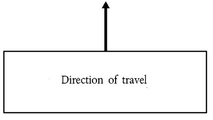
The railway undertaking must ensure that an approaching train is clearly visible and recognisable as such, by the presence and layout of its lit white front-end lights.
The forward facing front-end of the leading vehicle of a train must be fitted with three lights in an isosceles triangle, as shown below. These lights must always be lit when the train is being driven from that end.

The front lights must optimise train detectability (for example, to track workers and those using public crossings) (marker lights), provide sufficient visibility for the train driver (illumination of the line ahead, lineside information markers/boards, etc.) (head lights) by night and during low light conditions and must not dazzle the drivers of oncoming trains.
The spacing, the height above rails, the diameter, the intensity of the lights, the dimensions and shape of the emitted beam in both day and night time operation are defined in the rolling stock TSI(hereinafter referred to as ‘RST TSI’).
4.2.2.1.3. Rear end
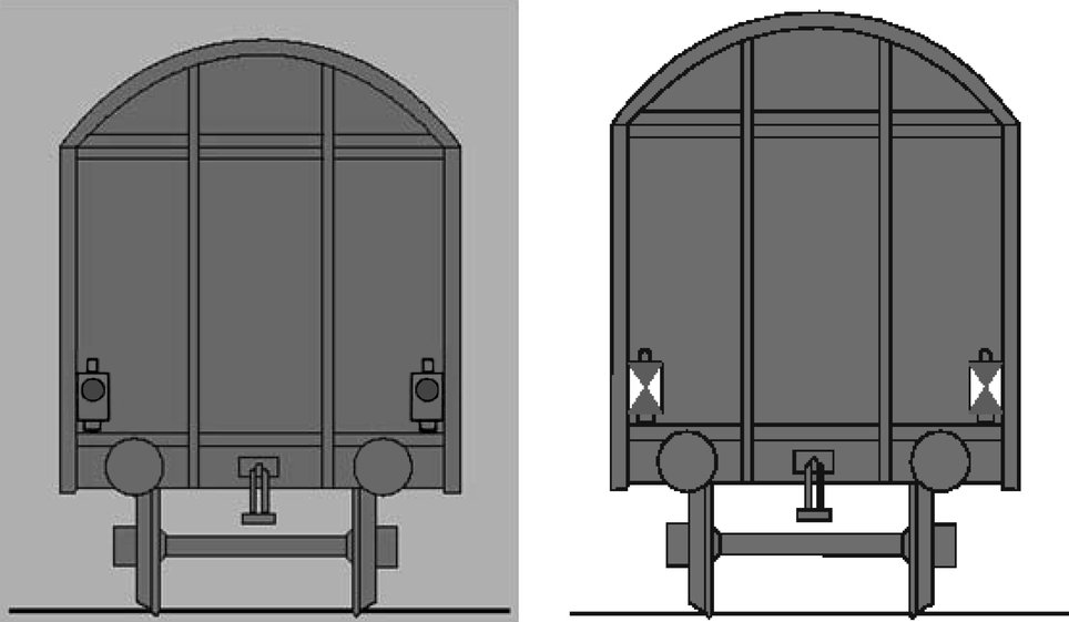
The railway undertaking must provide the required means of indicating the rear of a train. The rear end signal must only be exhibited on the rear of the last vehicle of the train. It must be displayed as shown below.
4.2.2.1.3.1. Passenger trains
The rear end indication of a passenger train must consist of 2 steady red lights at the same height above buffer on the transversal axis.
4.2.2.1.3.2. Freight trains in international traffic
The Member State must notify which of the following requirements will apply on the network of its Member State for trains that cross a border between Member States:
Either
|
— |
2 steady red lights, or |
|
— |
2 reflective plates of the following shape with white side triangles and red top and bottom triangle:
|
The lamps or plates must be on the same height above buffer on the transversal axis. Member States that require 2 reflective plates must also accept 2 steady red lights as train rear end indication.
4.2.2.1.3.3. Freight trains not crossing a border between member states
For freight trains not crossing a border between Member States the train rear end indication is an open point (see Appendix U).
4.2.2.2.
4.2.2.2.1. General requirement
The railway undertaking must ensure that trains are fitted with an audible warning device to indicate the approach of a train.
4.2.2.2.2. Control
The activation of the audible warning device must be possible from all driving positions.
4.2.2.3.
Each vehicle must have a number to uniquely identify it from any other rail vehicle. This number must be prominently displayed at least on each longitudinal side of the vehicle.
It must also be possible to identify operational restrictions applicable to the vehicle.
Further requirements are specified in Appendix P.
4.2.2.4.
4.2.2.4.1. Safety of load
The railway undertaking must make sure that freight vehicles are safely and securely loaded and remain so throughout the journey.
4.2.2.4.2. Safety of passengers
The railway undertaking must ensure that passenger transport is undertaken safely at the departure and during the journey.
4.2.2.5.
The railway undertaking must define the rules and procedures to be followed by his staff so as to ensure that the train is in compliance with the allocated path.
Train composition requirements must take into account the following elements:
|
(a) |
the vehicles
|
|
(b) |
the train
|
|
(c) |
the weight and axle load
|
|
(d) |
the maximum speed of the train
|
|
(e) |
the kinematic envelope
|
Additional constraints may be required or imposed due to the type of braking regime or traction type on a particular train.
4.2.2.6.
4.2.2.6.1. Minimum requirements of the braking system
All vehicles in a train must be connected to the continuous automatic braking system as defined in the RST TSI.
The first and last vehicles (including any traction units) in any train must have the automatic brake operative.
In the case of a train becoming accidentally divided into two parts, both sets of detached vehicles must come automatically to a stand as a result of a maximum application of the brake.
4.2.2.6.2. Braking performance
The infrastructure manager must provide the railway undertaking with the actual performance required. This data shall include, if necessary, conditions of use of braking systems possibly affecting the infrastructure such as magnetic, regenerative and eddy-current brake.
The railway undertaking is responsible for ensuring that the train has sufficient braking performance by providing braking rules for its staff to be followed.
The rules concerning braking performance have to be managed within the infrastructure manager’s and railway undertaking’s safety management system.
Further requirements are specified in Appendix T.
4.2.2.7.
4.2.2.7.1. General requirement
The railway undertaking must define the process to ensure that all safety-related on-train equipment is in a fully functional state and that the train is safe to run.
The railway undertaking must inform the infrastructure manager of any modification to the characteristics of the train affecting its performance or any modification that might affect the ability to accommodate the train in its allocated path.
The infrastructure manager and the railway undertaking must define and keep up to date conditions and procedures for train running in degraded mode.
4.2.2.7.2. Data required
The data required for safe and efficient operation and the process by which this data must be forwarded must comprise:
|
— |
the train identification |
|
— |
the identity of the railway undertaking responsible for the train |
|
— |
the actual length of the train |
|
— |
if a train carries passengers or animals when it is not scheduled to do so |
|
— |
any operational restrictions with an indication of the vehicle(s) concerned (gauge, speed restrictions, etc.) |
|
— |
information the infrastructure manager requires for the transport of dangerous goods. |
The railway undertaking must ensure that this data is made available to the infrastructure manager(s) prior to the departure of the train.
The railway undertaking must advise the infrastructure manager(s) if a train will not occupy its allocated path or is cancelled.
4.2.2.8.
The driver must be able to observe signals and lineside markers, and they must be observable by the driver. The same applies for other types of lineside signs if they are safety related.
Therefore, signals, lineside markers, signs and information boards must be designed and positioned in such a consistent way to facilitate this. Issues that must be taken into account include:
|
— |
that they are suitably sited so that train headlights allow the driver to read the information, |
|
— |
suitability and intensity of lighting, where required to illuminate the information, |
|
— |
where retro-reflectivity is employed, the reflective properties of the material used are in compliance with appropriate specifications and the signs are fabricated so that train headlights easily allow the driver to read the information. |
Driving cabs must be designed in such a consistent way that the driver is able to easily see the information displayed to him.
4.2.2.9.
A means of onboard monitoring of driver vigilance is necessary. This shall intervene to bring the train to a stand if the driver does not react within a certain time; the time range is specified in the rolling stock TSI.
4.2.3. Specifications relating to train operations
4.2.3.1.
In accordance with Directive 2001/14/EC the infrastructure manager must advise what data is required when a train path is requested.
4.2.3.2.
Each train must be identified by a train running number. The train running number is given by the infrastructure manager when allocating a train path and must be known by the railway undertaking and all infrastructure managers operating the train. The train running number must be unique per network. Changes of train running number during a train journey should be avoided.
4.2.3.2.1. Format of train running number
The train running number format is defined in the control-command and signalling TSI (hereinafter referred to as ‘CCS TSI’)
4.2.3.3.
4.2.3.3.1. Checks and tests before departure
The railway undertaking must define the checks and tests to ensure that any departure is undertaken safely (e.g. doors, load, brakes).
4.2.3.3.2. Informing the infrastructure manager of the train's operational status
The railway undertaking shall inform the infrastructure manager when a train is ready for access to the network.
The railway undertaking must inform the infrastructure manager of any anomaly affecting the train or its operation having possible repercussions on the train's running prior to departure and during the journey.
4.2.3.4.
4.2.3.4.1. General requirements
Traffic management must ensure the safe, efficient and punctual operation of the railway, including effective recovery from service disruption.
The infrastructure manager must determine procedures and means for:
|
— |
the real time management of trains, |
|
— |
operational measures to maintain the highest possible performance of the infrastructure in case of delays or incidents, whether actual or anticipated, and |
|
— |
the provision of information to the railway undertaking(s) in such cases. |
Any additional processes required by the railway undertaking and which affect the interface with the infrastructure manager(s) can be introduced after being agreed with the infrastructure manager.
4.2.3.4.2. Train reporting
4.2.3.4.2.1. Data required for train position reporting
The infrastructure manager must:
|
(a) |
provide a means of real time recording of the times at which trains depart from, arrive at or pass appropriate pre-defined reporting points on their networks and the delta-time value; |
|
(b) |
provide the specific data required in relation to train position reporting. Such information must include:
|
4.2.3.4.2.2. Predicted hand over time
The infrastructure manager must have a process, which enables an indication of the estimated number of minutes of deviation from the scheduled time a train is scheduled to be handed over from one infrastructure manager to another.
This must include information on service disruption (description and location of problem).
4.2.3.4.3. Dangerous goods
The railway undertaking must define the procedures to supervise the transport of dangerous goods.
These procedures must include:
|
— |
the provisions as specified in Directive 2008/68/EC of the European Parliament and of the Council (1) |
|
— |
advice to the driver of the presence and position of dangerous goods on the train |
|
— |
information the infrastructure manager requires for transport of dangerous goods |
|
— |
determination, in conjunction with the infrastructure manager, of lines of communication and planning of specific measures in case of emergency situations involving the goods. |
4.2.3.4.4. Operational quality
The infrastructure manager and the railway undertaking must have processes in place to monitor the efficient operation of the all the services concerned.
Monitoring processes must be designed to analyse data and detect underlying trends, both in terms of human error and system error. The results of this analysis must be used to generate improvement actions, designed to eliminate or mitigate against events which could compromise the efficient operation of the network.
Where such improvement actions would have network-wide benefits, involving other infrastructure managers and railway undertakings, they must, subject to commercial confidentiality, be communicated accordingly.
Events that have significantly disrupted operations must be analysed as soon as possible by the infrastructure manager. Where appropriate, and in particular where one of their staff is concerned, the infrastructure manager must invite those railway undertaking(s) involved in the event concerned to participate in the analysis. Where the result of such analysis leads to network improvement recommendations designed to eliminate or mitigate against causes of accidents/incidents, these must be communicated to all relevant infrastructure managers and railway undertakings concerned.
These processes shall be documented and subject to internal audit.
4.2.3.5.
Data pertaining to the running of a train must be recorded and retained for the purposes of:
|
— |
Supporting systematic safety monitoring as a means of preventing incidents and accidents. |
|
— |
Identifying driver, train and infrastructure performance in the period leading up to and (if appropriate) immediately after an incident or accident, to enable the identification of causes related to train driving or train equipment, and supporting the case for new or changed measures to prevent recurrence. |
|
— |
To record information relating to the performance of both the locomotive/traction unit and the person driving. |
It must be possible to match recorded data to:
|
— |
the date and time of the recording |
|
— |
the precise geographic location of the event being recorded (distance in kilometres from a recognisable location) |
|
— |
the train identification |
|
— |
the identity of the driver |
Requirements with regard to storage, periodic evaluation of and access to this data are specified in relevant national laws of the Member State:
|
— |
in which the railway undertaking is licensed (with regard to on-board recorded data), or |
|
— |
of the Member State in which the infrastructure is located (with regard to data recorded outside the train). |
4.2.3.5.1. Recording of supervision data outside the train
As a minimum, the infrastructure manager must record the following data:
|
— |
the failure of line-side equipment associated with the movement of trains (signalling, points etc.); |
|
— |
the detection of an overheating axle bearing, where this equipment is provided; |
|
— |
communication between the train driver and infrastructure manager’s staff authorising train movements. |
4.2.3.5.2. Recording of supervision data on-board the train
As a minimum, the railway undertaking must record the following data:
|
— |
the passing of signals at danger or ‘end of movement authority’ without authority |
|
— |
application of the emergency brake |
|
— |
speed at which the train is running |
|
— |
any isolation or overriding of the on-board train control (signalling) systems |
|
— |
operation of the audible warning device (horn) |
|
— |
operation of door controls (release, closure) |
|
— |
detection by on-board hot axle box detectors, if fitted |
|
— |
identity of the cab for which data is being recorded to be checked. |
4.2.3.6.
4.2.3.6.1. Advice to other users
The infrastructure manager in conjunction with the railway undertaking(s) must define a process to immediately inform each other of any situation that impedes the safety, performance and/or the availability of the rail network or rolling stock.
4.2.3.6.2. Advice to train drivers
In any case of degraded operation associated with the infrastructure manager’s area of responsibility, the infrastructure manager must give formal instructions to drivers on what measures to take in order to safely overcome the degradation.
4.2.3.6.3. Contingency arrangements
The infrastructure manager in conjunction with all the railway undertakings operating over his infrastructure, and neighbouring infrastructure managers as appropriate, must define, publish and make available appropriate contingency measures and assign responsibilities based on the requirement to reduce any negative impact as a result of degraded operation.
The planning requirements and the response to such events must be proportional to the nature and potential severity of the degradation.
These measures, which must as a minimum include plans for recovering the network to ‘normal’ status, may also address:
|
— |
rolling stock failures (for example, those which could result in substantial traffic disruption, the procedures for rescuing failed trains); |
|
— |
infrastructure failures (for example, when there has been a failure of the electric power or the conditions under which trains may be diverted from the booked route); |
|
— |
extreme weather conditions. |
The infrastructure manager must establish and keep updated contact information for key infrastructure manager and railway undertaking staff who may be contacted in the event of service disruption leading to degraded operation. This information must include contact details both during and outside office hours.
The railway undertaking must submit this information to the infrastructure manager and advise the infrastructure manager of any changes to these contact details.
The infrastructure manager must advise all the railway undertaking(s) of any changes to his details.
4.2.3.7.
The infrastructure manager must, in consultation with:
|
— |
all railway undertakings operating over his infrastructure, or, where appropriate, representative bodies of railway undertakings operating over his infrastructure, |
|
— |
neighbouring infrastructure managers, as appropriate, |
|
— |
local authorities, representative bodies of the emergency services (including fire fighting and rescue) at either local or national level, as appropriate. |
define, publish and make available appropriate measures to manage emergency situations and restore the line to normal operation.
Such measures shall typically cover:
|
— |
collisions, |
|
— |
fires on train, |
|
— |
evacuation of trains, |
|
— |
accidents in tunnels, |
|
— |
incidents involving dangerous goods |
|
— |
derailments |
The railway undertaking must provide the infrastructure manager with any specific information in respect to these circumstances, especially in respect to the recovery or re-railing of their trains.
Additionally, the railway undertaking must have processes to inform passengers about onboard emergency and safety procedures.
4.2.3.8.
The railway undertaking must define appropriate procedures to assist the train crew in degraded situations in order to avoid or decrease delays caused by technical or other failures of the rolling stock (for example, lines of communication, measures to be taken in case of evacuation of a train).
4.3. Functional and technical specifications of the interfaces
In the light of the essential requirements set out in Chapter 3, the functional and technical specifications of the interfaces are as follows:
4.3.1. Interfaces with the infrastructure TSI
|
Reference conventional rail operation TSI |
|
Reference conventional rail infrastructure TSI |
|
|
Parameter |
Point |
Parameter |
Point |
|
Braking performance |
4.2.2.6.2 |
Longitudinal track resistance |
4.2.7.2 |
|
Modifications to information contained in the route book |
4.1.2.2.2 |
Operating rules |
4.4 |
|
Degraded operation |
4.2.3.6 |
4.3.2. Interfaces with the control-command and signalling TSI
|
Reference conventional rail operation TSI |
|
Reference conventional rail CCS draft TSI |
|
|
Parameter |
Point |
Parameter |
Point |
|
Rule book |
4.2.1.2.1 |
|
|
|
Operating rules |
4.4 |
Operating rules |
4.4 |
|
Signal and lineside marker sighting |
4.2.2.8 |
Visibility of track-side control-command objects |
4.2.16 |
|
Braking performance |
4.2.2.6 |
Train braking performance and characteristics |
4.3.2.3 |
|
Rule Book |
4.2.1.2.1 |
Use of sanding equipment |
4.2.10 |
|
Train running number |
4.2.3.2.1 |
ETCS DMI |
4.2.12 |
|
|
GSM-R DMI |
4.2.13 |
|
|
Data recording onboard |
4.2.3.5 |
Interface to data recording for regulatory purposes |
4.2.15 |
4.3.3. Interfaces with the rolling stock TSI
4.3.3.1.
|
Reference conventional rail operation TSI |
|
Reference conventional rail locom. and pass. TSI |
|
|
Parameter |
Point |
Parameter |
Point |
|
Contingency arrangements |
4.2.3.6.3 |
Rescue coupling |
4.2.2.2.4 |
|
Train composition |
4.2.2.5 |
Interface with infrastructure: axle load parameter |
4.2.3.2 |
|
Minimum requirements of the braking system |
4.2.2.6.1 |
Braking performance |
4.2.4.5 |
|
Train visibility |
4.2.2.1 |
External front and rear lights |
4.2.7.1 |
|
Train audibility |
4.2.2.2 |
Horn |
4.2.7.2 |
|
Signal sighting |
4.2.2.8 |
External visibility |
4.2.9.1.3 |
|
Optical characteristics of the windscreen |
4.2.9.2.2 |
||
|
Internal lighting |
4.2.9.1.8 |
||
|
Driver vigilance |
4.2.2.9 |
Driver's activity control function |
4.2.9.3.1 |
|
Data recording |
4.2.3.5.2 |
Recording device |
4.2.9.5 |
4.3.3.2.
|
Reference conventional rail operation TSI |
|
Reference conventional freight wagon draft TSI |
|
|
Parameter |
Point |
Parameter |
Point |
|
Rear end |
4.2.2.1.3.2 |
Attachment devices for rear-end signal |
4.2.6.3 |
|
Rear end |
4.2.2.1.3.2 |
Rear-end signal |
Annex E |
|
Train composition |
4.2.2.5 |
Gauging |
4.2.3.1 |
|
Train composition |
4.2.2.5 |
Axle load parameter |
4.2.3.3.2 |
|
Contingency arrangements |
4.2.3.6.3 |
Lifting and jacking |
4.2.2.2 |
|
Train braking |
4.2.2.6 |
Brake |
4.2.4 |
4.3.4. Interfaces with the Energy TSI
|
Reference conventional rail operation TSI |
|
Reference conventional rail energy TSI |
|
|
Parameter |
Point |
Parameter |
Point |
|
Description of the line and the relevant line side equipment associated with the lines worked over |
4.2.1.2.2 |
Management of power supply |
4.4.2 |
|
Informing the driver in real time |
4.2.1.2.2.3 |
|
|
|
Modifications to information contained within the route book |
4.2.1.2.2.2 |
Execution of works |
4.4.3 |
4.4. Operating rules
The rules and procedures enabling coherent operation of new and different structural subsystems intended to be used in the TEN, and in particular those that are linked directly to the operation of a new train control and signalling system, must be identical where identical situations exist.
To this end, the operating rules for the European Rail Traffic Management System (ERTMS/ETCS) and for ERTMS/GSM-R radio system are specified in Appendix A.
Other operating rules, which are able to be standardised across the TEN, will be specified in Appendix B.
4.5. Maintenance rules
Not applicable
4.6. Professional qualifications
In accordance with point 2.2.1 of this TSI, this point deals with professional and linguistic competency and the assessment process required for staff to attain this competency.
4.6.1. Professional competency
Staff (including contractors) of the railway undertaking and the infrastructure manager must have attained appropriate professional competency to undertake all necessary safety-related duties in normal, degraded and emergency situations. Such competency comprises professional knowledge and the ability to put this knowledge into practice.
Minimum elements relevant to professional qualification for individual tasks can be found in Appendices J and L.
4.6.1.1.
Taking these appendices into account and dependant on the duties of the individual staff member concerned, the knowledge required will comprise the following:
|
(a) |
general railway operation with particular emphasis on safety-critical activity:
|
|
(b) |
appropriate knowledge of safety-related tasks in respect to procedures and interfaces for:
|
4.6.1.2.
The ability to apply this knowledge in routine, degraded and emergency situations will require staff to be fully acquainted with:
|
— |
the method and principles for applying these rules and procedures |
|
— |
the process for the use of line-side equipment and rolling stock, as well as any specific safety-related equipment |
|
— |
the principles of the safety management system to avoid the introduction of any undue risk to people and process. |
Staff must also possess a general ability to adapt to the different circumstances an individual may encounter.
Railway undertakings and infrastructure managers are required to establish a competence management system to ensure that the individual competency of their staff involved is assessed and maintained. Additionally, training must be provided, as necessary, to ensure that knowledge and skills are kept up to date, especially in relation to weaknesses or deficiencies in system or individual performance.
4.6.2. Linguistic competency
4.6.2.1.
The infrastructure manager and the railway undertaking are required to ensure that their relevant personnel are competent in the use of the communication protocols and principles set out in this TSI.
Where the operating language used by the infrastructure manager differs from that habitually used by the railway undertaking’s personnel, such linguistic and communications training must form a critical part of the railway undertaking’s overall competency management system.
Railway undertaking staff whose duties require them to communicate with staff of the infrastructure manager in connection with safety-critical matters, whether in routine, degraded or emergency situations, must have a sufficient level of knowledge in the operating language of the infrastructure manager.
4.6.2.2.
The level of knowledge in the infrastructure manager’s language must be sufficient for safety purposes.
|
(a) |
As a minimum this must comprise of the driver being able to:
|
|
(b) |
Other members of the train crew whose duties require them to communicate with the infrastructure manager on safety-critical matters, must as a minimum, be able to send and understand information describing the train and its operational status. |
Guidance on the appropriate levels of competency is defined in Appendix E. The level of knowledge for drivers must be at least level 3. The level of knowledge for staff accompanying trains must be at least level 2.
4.6.3. Initial and ongoing assessment of staff
4.6.3.1.
Railway undertakings and infrastructure managers are required to define the assessment process for their staff.
It is recommended that account be taken of each of the following:
A. Selection of personnel
|
— |
evaluation of individual experience and competence |
|
— |
evaluation of individual competence in the use of any required foreign language(s) or the aptitude to learn them |
B. Initial professional training
|
— |
analysis of training needs; |
|
— |
training resources |
|
— |
training of the trainers |
C. Initial assessment
|
— |
basic conditions; |
|
— |
assessment programme, including practical demonstration; |
|
— |
qualification of the trainers. |
|
— |
deliver a certificate of competency. |
D. Competency retention
|
— |
principles for retention of competency |
|
— |
methods to be followed |
|
— |
formalisation of the competency retention process. |
|
— |
assessment process. |
E. Refresher training
|
— |
principles for ongoing training (including language) |
4.6.3.2.
4.6.3.2.1. Development of the analysis of training needs
The railway undertaking and the infrastructure manager must undertake an analysis of training needs for their relevant staff.
This analysis must set out both scope and complexity and take into account the risks associated with the operation of trains on the TEN, especially in relation to human capabilities and limitations (human factors) which may come about as a result of:
|
— |
differences in operating practices between infrastructure managers and the risks associated with changing between these; |
|
— |
the differences between tasks, operating procedures and communication protocols; |
|
— |
any difference in the ‘operating’ language used by the infrastructure manager’s personnel; |
|
— |
local operating instructions which may include special procedures or particular equipment to be applied in certain cases, for example a specific tunnel. |
Guidance on the elements that should be considered can be found in the appendices referred to in point 4.6.1. As appropriate, elements of the training for staff must be put in places which take these into account.
It is possible that due to the type of operation envisaged by a railway undertaking or the nature of the network being run by an infrastructure manager, some of the elements in the appendices referred to in point 4.6.1. will not be appropriate. The analysis of training needs must document those not deemed appropriate and the reasons why.
4.6.3.2.2. Updating the analysis of training needs
The railway undertaking and the infrastructure manager must define a process for reviewing and updating their individual training needs, taking into account issues such as previous audits, system feedback and known changes to rules and procedures, infrastructure and technology.
4.6.3.2.3. Specific elements for train crew and auxiliary staff
4.6.3.2.3.1. Infrastructure knowledge
The railway undertaking must ensure that the on board staff has appropriate knowledge for the relevant infrastructure.
The railway undertaking must define the process by which knowledge of on board staff of the routes worked over is acquired and maintained. This process must be:
|
— |
based upon the route information provided by the infrastructure manager and |
|
— |
in accordance with the process described in point 4.2.1. |
4.6.3.2.3.2. Knowledge of rolling stock
The railway undertaking must define the process for the acquisition and retention of traction and rolling stock knowledge by its train crew.
4.6.3.2.3.3. Auxiliary staff
The railway undertaking must make sure that the auxiliary staff (for example, catering and cleaning) not forming part of the ‘train crew’ is, in addition to their basic instruction, trained to respond to the instructions of the fully trained members of the ‘train crew’.
4.7. Health and safety conditions
4.7.1. Introduction
Staff specified in point 4.2.1 as staff performing safety-critical tasks in accordance with point 2.2 must have appropriate fitness to ensure that overall operational and safety standards are met.
Railway undertakings and infrastructure managers must set up and document the process they put in place to meet the medical, psychological and health requirements for their staff within their safety management system.
Medical examinations as specified in point 4.7.4 and any associated decisions on the individual fitness of staff must be conducted by a recognised occupational doctor.
Staff must not perform safety-critical work whilst vigilance is impaired by substances such as alcohol, drugs or psychotropic medication. Therefore, the railway undertaking and the infrastructure manager must have in place procedures to control the risk that staff attend for work under the influence of such substances, or consume such substances at work.
National rules of the Member State where a train service is operated apply with regard to defined limits of the above mentioned substances.
4.7.2. Deleted
4.7.3. Deleted
4.7.4. Medical examinations and psychological assessments
4.7.4.1.
4.7.4.1.1. Minimum content of the medical examination
Medical examinations must cover:
|
— |
General medical examination; |
|
— |
Examinations of sensory functions (vision, hearing, colour perception); |
|
— |
Urine or blood analysis for the detection of diabetes mellitus and other conditions as indicated by the clinical examination; |
|
— |
Screening for drugs of abuse. |
4.7.4.1.2. Psychological assessment
The aim of the psychological assessment is to support the railway undertaking in the appointment and management of staff who have the cognitive, psychomotor, behavioural and personality capabilities to perform their roles safely.
In determining the content of the psychological assessment the psychologist must, as a minimum, take the following criteria into account relevant to the requirements of each safety function:
|
(a) |
Cognitive:
|
|
(b) |
Psychomotor:
|
|
(c) |
Behavioural and personality
|
If the psychologist omits any of those elements, the respective decision must be justified and documented.
4.7.4.2.
4.7.4.2.1. Periodicity of periodic medical examinations
At least one systematic medical examination must be performed:
|
— |
Every 5 years for staff aged up to 40; |
|
— |
Every 3 years for staff aged between 41 and 62; |
|
— |
Every year for staff aged over 62. |
Increased periodicity of examination must be set by the occupational doctor if the state of health of the member of the staff requires so.
4.7.4.2.2. Minimum content of the periodic medical examination
If the worker complies with the criteria required at the examination, which is carried out before practising an occupation, the periodic specialised examinations must include as a minimum:
|
— |
General medical examination; |
|
— |
Examination of sensory functions (vision, hearing, colour perception); |
|
— |
Urine or blood analysis for the detection of diabetes mellitus and other conditions as indicated by the clinical examination; |
|
— |
Screening for drugs of abuse where clinically indicated. |
4.7.4.2.3. Additional medical examinations and/or psychological assessments
Besides the periodic medical examination, an additional specific medical examination and/or psychological assessment must be performed where there is reasonable ground for doubting the medical or psychological fitness of a member of staff or reasonable suspicion of use of drugs of abuse or abuse or inappropriate use of alcohol. This would be the case especially after an incident or accident caused by human error on the part of the individual.
The employer must request a medical examination after any sickness absence exceeding 30 days. In suitable cases such an examination can be limited to an assessment by the occupational doctor based on available medical information indicating that the employee’s fitness for work has not been affected.
The railway undertaking and the infrastructure manager must put systems in place to ensure that such additional examinations and assessments are undertaken as appropriate.
4.7.5. Medical requirements
4.7.5.1.
Staff must not suffer from medical conditions or take medical treatment likely to cause:
|
— |
Sudden loss of consciousness; |
|
— |
Impairment of awareness or concentration; |
|
— |
Sudden incapacity; |
|
— |
Impairment of balance or co-ordination; |
|
— |
Significant limitation of mobility. |
The following vision and hearing requirements must be met:
4.7.5.2.
|
— |
Aided or unaided distance visual acuity: 0,8 (right eye + left eye — measured separately); minimum of 0,3 for the worse eye. |
|
— |
Maximum corrective lenses: hypermetropia + 5/myopia — 8. The occupational doctor may allow values outside this range in exceptional cases and after having sought the opinion of an eye specialist. |
|
— |
Intermediate and near vision: sufficient whether aided or unaided. |
|
— |
Contact lenses are allowed. |
|
— |
Normal colour vision: using a recognised test, such as the Ishihara, completed by another recognised test if required. |
|
— |
Vision field: normal (absence of any abnormality affecting the task to be performed) |
|
— |
Vision for both eyes: present |
|
— |
Binocular vision: present |
|
— |
Contrast sensitivity: good |
|
— |
Absence of progressive eye disease |
|
— |
Lens implants, keratotomies and keratectomies are allowed only on condition that they are checked on a yearly basis or according to a periodicity set by the occupational doctor. |
4.7.5.3.
Sufficient hearing confirmed with tone audiogram, that is:
|
— |
Hearing good enough to keep a phone conversation going and be able to hear alert tones and radio messages. |
|
— |
The following values given for information should be taken as guidelines: |
|
— |
The hearing deficiency must not be higher than 40 dB at 500 and 1 000 Hz; |
|
— |
The hearing deficiency must not be higher than 45 dB at 2 000 Hz for the ear with the worst air conduction of sound. |
4.8. Registers of infrastructure and vehicles
Due to the characteristics of the registers of infrastructure and vehicles, as defined in Articles 33, 34 and 35 of Directive 2008/57/EC, these registers are not suitable for the particular requirements of the operation and traffic management subsystem. Therefore this TSI specifies nothing in respect of these registers.
However, there is an operational requirement for certain infrastructure related data items to be made available to a railway undertaking and conversely for certain rolling stock related items to be made available to an infrastructure manager, as specified in point 4.8.1 and point 4.8.2. In both cases the data concerned must be complete and accurate.
4.8.1. Infrastructure
The requirements for the conventional rail infrastructure related data items with regard to the operation and traffic management subsystem, and which must be made available to railway undertakings, are specified in Appendix D. The infrastructure manager is responsible for the correctness of the data.
4.8.2. Rolling stock
The following rolling stock related data items must be available to infrastructure managers. The keeper is responsible for the correctness of the data:
|
— |
whether the vehicle is constructed from materials which can be hazardous in case of accidents or fire (for example, asbestos) |
|
— |
length over buffers. |
5. INTEROPERABILITY CONSTITUENTS
5.1. Definition
According to Article 2(f) of Directive 2008/57/EC, ‘interoperability constituents’ means ‘any elementary component, group of components, subassembly or complete assembly of equipment incorporated or intended to be incorporated into a subsystem, upon which the interoperability of the rail system depends directly or indirectly. The concept of a “constituent” covers both tangible objects and intangible objects such as software’.
5.2. List of constituents
In respect to the operation and traffic management subsystem, there are no interoperability constituents.
6. ASSESSMENT OF CONFORMITY AND/OR SUITABILITY FOR USE OF THE CONSTITUENTS AND VERIFICATION OF THE SUBSYSTEM
6.1. Interoperability constituents
As this TSI does not yet specify any interoperability constituents, no assessment arrangements are discussed.
6.2. Operation and traffic management subsystem
6.2.1. Principles
The operation and traffic management subsystem is a functional subsystem according to Annex II to Directive 2008/57/EC.
In conformity with Articles 10 and 11 of Directive 2004/49/EC, railway undertakings and infrastructure managers must demonstrate compliance with the requirements of this TSI within their safety management system when applying for any new or amended safety certificate or safety authorisation.
The common safety methods on conformity assessment require national safety authorities to set up an inspection regime to supervise and monitor the day to day compliance with the safety management system including all TSIs. It should be noted that none of the elements contained within this TSI require separate assessment by a Notified Body.
Requirements in this TSI that refer to structural subsystems and are listed in the interfaces (point 4.3) are assessed under the relevant structural TSIs.
7. IMPLEMENTATION
7.1. Principles
Implementation of this TSI and conformity with the relevant points of this TSI must be determined in accordance with an implementation plan that must be drawn up by each Member State for the lines for which they are responsible.
This plan must take into account:
|
(a) |
the specific human factors issues associated with operating any given line; |
|
(b) |
the individual operating and safety elements of each line involved; and |
|
(c) |
whether implementation of the element(s) under consideration is to be:
|
|
(d) |
the relationship with implementation with the other subsystems (control-command and signalling, rolling stock, etc.). |
At this time any specific exceptions that may be applicable should be taken into account and documented as part of the plan.
The implementation plan must take into account the various levels of potential for implementation from any of the following events, namely when:
|
(a) |
a railway undertaking or infrastructure manager commences operations, |
|
(b) |
a renewal or upgrade to the existing operational systems of a railway undertaking or infrastructure manager is introduced, |
|
(c) |
new or upgraded infrastructure, energy, rolling stock or command control & signalling subsystems, requiring a corresponding set of operating procedures, are put into service. |
It is commonly understood that the full implementation of all elements of this TSI cannot be complete until the hardware (infrastructure, control and command, etc.) that is to be operated has been harmonised. The guidelines set out in this Chapter must therefore only be seen as an interim phase supporting migration to the target system.
7.2. Implementation guidelines
There are three distinct elements to implementation:
|
(a) |
Confirmation that any existing systems and processes comply with the requirements of this TSI |
|
(b) |
Adaptation of any existing systems and processes to comply with the requirements of this TSI |
|
(c) |
New systems and processes arising from implementation of other subsystems
|
7.3. Specific cases
7.3.1. Introduction
The following special provisions are permitted in the specific cases below.
These specific cases belong to two categories:
|
(a) |
the provisions apply either permanently (case ‘P’), or temporarily (case ‘T’). |
|
(b) |
In temporary cases Member States shall conform with the relevant subsystem either by 2016 (case ‘T1’), or by 2024 (case ‘T2’). |
7.3.2. List of specific cases
7.3.2.1.
For the implementation of point 4.2.2.1.3.2 of this TSI, trains which are operated solely on the 1 520 mm gauge network of Estonia, Latvia and Lithuania may use another specified train rear end signal.
7.3.2.2.
For the implementation of 4.2.3.2.1 of this TSI, Ireland and United Kingdom are using alphanumeric number in the existing systems. The MS set out the requirements and time schedule for the transition from alphanumeric train running numbers to numeric train running numbers in the target system.
(1) OJ L 260, 30.9.2008, p. 13.
Appendix A
ERTMS/ETCS OPERATING RULES
The operating rules for ERTMS/ETCS and ERTMS/GSM-R are specified in the Technical Document ‘ETCS and GSM-R rules and principles — Version 1’ published on the ERA website (http://www.era.europa.eu).
Appendix B
OTHER RULES ENABLING A COHERENT OPERATION
A. GENERAL
Reserved
B. STAFF SAFETY AND SECURITY
Reserved
C. OPERATIONAL INTERFACE WITH SIGNALLING AND COMMAND AND CONTROL EQUIPMENT
C1. Sanding
If the train is equipped with manually activated sanding device, the driver shall always be allowed to apply sand but shall avoid it wherever possible:
|
— |
in the area of points and crossings |
|
— |
during braking at speeds less than 20 km/h. |
|
— |
when at a standstill. |
The exceptions to this are
|
— |
if there is a risk of SPAD (Signal Passed at Danger), or other serious incident and the application of sand would assist adhesion |
|
— |
when starting away or |
|
— |
when required to test the sanding equipment on the traction unit. (Testing should normally be undertaken in areas specifically designated in the Infrastructure Register). |
C2. Activation of Hot Axle Box Detectors
Reserved
D. TRAIN MOVEMENTS
D1. Normal conditions
D2. Degraded conditions
Reserved
E. ANOMALIES, INCIDENTS AND ACCIDENTS
Reserved
Appendix C
SAFETY RELATED COMMUNICATIONS METHODOLOGY
INTRODUCTION
This Appendix sets out the rules for safety-related ground-to-mobile and mobile-to-ground communications applicable to information transmitted or exchanged for safety-critical situations on the interoperable network and in particular to:
|
— |
define the nature and structure of the safety-related messages; |
|
— |
define the methodology for voice transmission of those messages. |
This Appendix is to serve as basis:
|
— |
in order to enable the infrastructure manager to draw up the messages and books of forms. These elements shall be addressed to the railway undertaking at the same time as the rules and regulations are made available; for the Infrastructure Manager and the Railway Undertaking to draw up the documents for their staff (Books of Forms), instructions for staff authorising train movements and Appendix 1 to the Driver’s Rule Book ‘Manual of communication procedures’. |
The extent to which forms are used and their structure may vary. For some risks the use of forms will be appropriate, whilst for others it will not be appropriate.
In the context of a given risk, the Infrastructure Manager shall decide whether the use of a form is appropriate. A form should only be used if the value of its safety and performance benefits exceeds that of any safety and performance disadvantage.
The Infrastructure Managers must structure his communications protocol in a formalised way and in line with the following 3 categories:
|
— |
urgent (emergency) verbal messages; |
|
— |
written orders; |
|
— |
additional performance messages. |
To support the disciplined approach to transmission of these messages a Communications Methodology has been developed.
1. COMMUNICATIONS METHODOLOGY
1.1. Elements and principles of the methodology
1.1.1. Standard terminology to be used in the procedures
1.1.1.1.
Term transferring the opportunity to speak to the opposite party:
1.1.1.2.
|
— |
upon receiving a direct message Term confirming that the sent message has been received:
received
Term used to have the message repeated in the event of poor reception or misunderstanding
say again (+ speak slowly)
|
|
— |
upon reception of a message that has been read-back Terms used to ascertain whether a read-back message exactly matches the sent message:
correct
or not:
error (+ I say again)
|
1.1.1.3.
|
— |
if the message has ended:
out
|
|
— |
if break is temporary and does not break the connection Term used to keep the other party waiting:
wait
|
|
— |
if break is temporary but the connection is broken Term used to tell the other party that the communication is going to be broken but will be resumed later on:
I call again
|
1.1.1.4.
Term used to cancel the written order procedure underway:
If the message is then subsequently to be resumed, the procedure shall be repeated from the start.
1.1.2. Principles to be applied in the event of error or misunderstanding
To permit the correction of possible errors during communication, the following rules shall be applied:
1.1.2.1.
|
— |
error during transmission When a transmission error is discovered by the sender himself, the sender must request cancellation by sending the following procedure message:
error (+ prepare new form …)
or:
error + I say again
and then send the initial message again. |
|
— |
error during read-back When the sender discovers an error whilst the message is being read back to him, the sender shall send the following procedure messages:
error + I say again
and send the initial message again. |
1.1.2.2.
If one of the parties misunderstands a message he must ask the other party to repeat the message by using the following text:
1.1.3. Word, number, time, distance, speed and date spelling code
To help understanding and expressing messages in different situations, each term must be pronounced slowly and correctly by spelling out any words or names and figures likely to be misunderstood. Examples would be the identifying codes for signals or points.
The following spelling rules shall apply:
1.1.3.1.
The International Phonetic Alphabet shall be used.
|
A |
Alpha |
|
B |
Bravo |
|
C |
Charlie |
|
D |
Delta |
|
E |
Echo |
|
F |
Foxtrot |
|
G |
Golf |
|
H |
Hotel |
|
I |
India |
|
J |
Juliet |
|
K |
Kilo |
|
L |
Lima |
|
M |
Mike |
|
N |
November |
|
O |
Oscar |
|
P |
Papa |
|
Q |
Quebec |
|
R |
Romeo |
|
S |
Sierra |
|
T |
Tango |
|
U |
Uniform |
|
V |
Victor |
|
W |
Whisky |
|
X |
X-ray |
|
Y |
Yankee |
|
Z |
Zulu |
Example:
Points A B= points alpha-bravo.
Signal Number KX 835= signal Kilo X-Ray eight three five.
The Infrastructure Manager may add further letters, along with a phonetic pronunciation for each letter added, if required by the alphabet of the Infrastructure Manager’s operating language(s).
The Railway Undertaking may add further indications about pronunciation, as it deems necessary.
1.1.3.2.
Numbers shall be spoken digit by digit.
|
0 |
Zero |
|
1 |
One |
|
2 |
Two |
|
3 |
Three |
|
4 |
Four |
|
5 |
Five |
|
6 |
Six |
|
7 |
Seven |
|
8 |
Eight |
|
9 |
Nine |
Example: train 2183 = train two-one-eight-three.
Decimals shall be expressed by the word ‘point’.
Example: 12.50 = one-two-point-five-zero
1.1.3.3.
The time shall be given in local time, in plain language.
Example: 10:52 hours = ten fifty-two.
Whilst this is the principle, it would also be acceptable, whenever necessary, for the time to be spelled out digit by digit (one zero five two hours).
1.1.3.4.
Distances shall be expressed in kilometres and speeds in kilometres per hour.
Miles may be used if that unit is used on the infrastructure concerned.
1.1.3.5.
Dates shall be expressed in the usual manner.
Example: 10 December
1.2. Communications structure
The voice transmission of safety-related messages shall in principle comprise 2 phases as follows:
|
— |
identification and request for instructions; |
|
— |
transmission of the message itself and termination of the transmission. |
The first phase may be cut back or entirely skipped for top priority safety messages.
1.2.1. Rules for identification and requests for instruction
To enable the parties to identify one another, define the operational situation and transmit procedural instructions, the following rules shall apply:
1.2.1.1.
It is very important that at the beginning of each communication, other than very urgent top priority emergency messages, the persons who are going to communicate identify themselves. Drivers identify themselves by train running number and position. For communication between signaller and driver it is the signaller's lead responsibility to ensure that the right signaller and river are in communication. This is especially critical when communication is taking place in areas where communications boundaries overlap.
This principle shall apply even after an interruption during transmission.
The following messages shall be used for this purpose by the different parties.
|
— |
by the staff authorising train movements:
|
|
— |
by the driver:
|
It should be noted that the identification may be followed by an additional information message giving the staff authoring train movements enough details of the situation to determine precisely the procedure that the driver may subsequently be required to follow.
1.2.1.2.
Every application of a procedure supported by a written order must be preceded by a request for instructions.
The following terms shall be used to request instructions:
1.2.2. Rules for transmission of written orders and verbal messages
1.2.2.1.
Due to their urgent and imperative nature, these messages:
|
— |
may be sent or received while running; |
|
— |
may skip the identification part; |
|
— |
shall be repeated; |
|
— |
shall, as soon as possible, be followed by further information. |
1.2.2.2.
In order to reliably send or receive (at a standstill) the procedural messages contained in the Book of Forms, the following rules shall be followed:
1.2.2.2.1. Message sending
The form may be completed prior to transmitting the message so that the full text of the message can be sent in one single transmission.
1.2.2.2.2. Message receiving
The receiver of the message must fill in the form contained in the Book of Forms based upon the information given by the sender.
1.2.2.2.3. Read-back
All the predetermined railway messages in the Book of Forms shall be required to be read back. The read-back shall include the message shown in the grey field on the Forms, the ‘report back’ section and any additional or complementary information.
1.2.2.2.4. Acknowledgement of correct read-back
Every read-back message shall be followed by an acknowledgement of conformity or non-conformity given by the sender of the message.
or
followed by a repeat sending of the initial message
1.2.2.2.5. Acknowledgement
Every message received shall be acknowledged positively or negatively as follows:
or
1.2.2.2.6. Traceability and verification
A unique identification or authorisation number shall accompany all messages initiated from the ground:
|
— |
if the message concerns an action for which the driver requires a specific authorisation (e.g. passing a signal at danger, …):
|
|
— |
in all other cases (e.g. proceeding with caution, …):
|
1.2.2.2.7. Reporting Back
Every message comprising a request to ‘report back’ shall be followed by a ‘report’.
1.2.2.3.
Additional messages
|
— |
shall be preceded by the identification procedure; |
|
— |
shall be short and precise (limited wherever possible to information to be communicated and where it applies); |
|
— |
shall be read back and followed by an acknowledgement of correct read-back, or not |
|
— |
may be followed by a request for instructions or a request for further information. |
1.2.2.4.
Information messages with a variable content shall be:
|
— |
preceded by the identification procedure; |
|
— |
prepared before sending; |
|
— |
read back and followed by an acknowledgement of correct read-back, or not. |
2. PROCEDURAL MESSAGES
2.1. Nature of the messages
Procedural messages are used to send operational instructions associated with appropriate situations represented in the Driver's Rule Book.
They comprise the text of the message itself, corresponding to a situation, and a number identifying the message.
If the message requires the recipient to report back, the text of the report is also given.
These messages use predetermined wording prescribed by the Infrastructure Manager in his ‘operating language’ and they are presented in the form of pre-prepared forms in either paper format or in computer medium.
2.2. Forms
Forms are a formalised medium for communicating procedural messages. These messages are generally those associated with degraded working conditions. Typical examples would be the authority for a driver to pass a signal or an ‘end of movement authority’, the requirement to run at reduced speed in a particular area, or to examine the line. There may well be other circumstances that will require the use of such messages.
Their purpose is to:
|
— |
provide a common working document used in real-time by the staff authorising train movements and by the drivers; |
|
— |
provide the driver (especially when working in an unfamiliar or rare environment) with a reminder of the procedure he will required to follow |
|
— |
enable traceability of communications. |
In order to identify the forms, a unique code word or number relating to the procedure shall be developed. This could be based on the potential frequency that a form would be used. If, of all the forms being developed, the likelihood is that the one most often used is the one for passing a signal or EOA at danger, then this one could be numbered 001 and so on.
2.3. Book of Forms
Having identified all the forms to be used, the whole set must be collected into a document or a computer medium called the Book of Forms.
It is a joint document that will be used by the driver and the staff authorising the movement of trains when they communicate with each other. It is important therefore that the book used by the driver and the one used by the staff authorising the movement of trains are constructed and numbered in the same manner.
The Infrastructure Manager is responsible for drawing up the Book of Forms and the forms themselves in his ‘operating language’.
The language to be used when transmitting the messages shall always be the ‘operating language’ of the Infrastructure Manager.
The Book of Forms shall comprise two parts.
The first part contains the following items:
|
— |
a reminder about the utilisation of the Book of Forms; |
|
— |
an index of ground-originated Procedure Forms; |
|
— |
an index of driver-originated Procedure Forms, where appropriate; |
|
— |
the list of situations cross-referencing to which procedure form is to be used; |
|
— |
a glossary giving the situations to which each procedure form applies; |
|
— |
the code for spelling out messages (phonetic alphabet etc.). |
The second part contains the Procedure Forms themselves. These must be collected by the RU and given to the driver.
3. ADDITIONAL MESSAGES
Additional messages are information messages used to inform about situations of a rare nature and for which therefore a pre-determined form is considered unnecessary, or related to train running or to the technical condition of the train or the infrastructure, either;
|
— |
by the driver to inform the staff authorising train movements, or |
|
— |
by the staff authorising train movements to advise the driver |
To make it easier to describe the situations and construct the information messages, message guidelines, a glossary of railway terminology, a descriptive diagram of the rolling stock being employed and a descriptive statement of the infrastructure equipment (track, traction supply, etc.) may be beneficial.
3.1. Guideline structure for messages
These messages may be structured along the following lines:
|
Stage in the communication flow |
Message element |
||||||||
|
Reason for passing the information |
|
||||||||
|
Observation |
|
||||||||
|
Position |
|
||||||||
|
|
||||||||
|
|
||||||||
|
Nature
|
… (see glossary) |
||||||||
|
State |
|
||||||||
|
|
||||||||
|
|
||||||||
|
Location with respect to the tracks
|
|
These messages may be followed by a request for instructions.
The elements of the messages are provided in both the language chosen by the Railway Undertaking and in the operating language(s) of the Infrastructure Managers concerned.
3.2. Glossary of Railway Terminology
The Railway Undertaking shall produce a glossary of railway terminology for each network over which his trains operate. It shall supply the terms in regular use in the language chosen by the Railway Undertaking and in the ‘operating’ language of the Infrastructure Manager(s) whose infrastructure is worked over.
The glossary shall be composed of two parts:
|
— |
a listing of terms by subject matter; |
|
— |
a listing of the terms in alphabetical order. |
3.3. Descriptive diagram of the rolling stock
If the Railway Undertaking feels it would benefit his operation a descriptive diagram of the rolling stock used shall be prepared. It shall list the names of the various components that may be the subject of communications with the different Infrastructure Managers concerned and include the common names for the standard terms in the language chosen by the Railway Undertaking and in the ‘operating’ language of the Infrastructure Manager(s) whose infrastructure is worked over.
3.4. Descriptive statement of the characteristics of the infrastructure equipment (track, traction supply, etc.)
If the Railway Undertaking feels it would benefit his operation a descriptive statement of the characteristics of the infrastructure equipment (track, traction supply, etc.) on the route worked over shall be prepared. This shall show the names of the various components that may be the subject of communications with the Infrastructure Manager(s) concerned. It shall include the common names for the standard terms in the language chosen by the Railway Undertaking and in the ‘operating’ language of the Infrastructure Manager(s) whose infrastructure is worked over.
4. TYPE AND STRUCTURE OF VERBAL MESSAGES
4.1. Emergency messages
Emergency messages are intended to give urgent operational instructions that are directly linked with the safety of the railway.
To avoid any risk of misunderstanding, messages must always be repeated once.
Classified according to need, the main messages which can be sent are indicated hereafter.
The Infrastructure Manager may, in addition, define other emergency messages according to the needs of his operation.
Emergency messages may be followed by a Written Order (see Subsection 2).
The type of text that goes to form Emergency messages must be included in Appendix 1 ‘Manual of communications procedures’ to the Driver’s Rule Book and in the documentation issued to staff authorising train movements.
4.2. Messages sent either by the ground or the driver
|
(a) |
Need to stop all trains: The need to stop all trains must be transmitted by means of an acoustic signal; if this is not available the following phrase must be used:
Emergency, stop all trains
Information on location or area is, if necessary, specified in the message. In addition, this message is to be quickly complemented, if possible, by the reason, the location of the emergency and the train's identification:
|
|
(b) |
Need to stop a particular train:
In this circumstance the name or number of the line or track on which the train is running may be used to complement the message. |
4.3. Messages issued by the driver
Need to cut the traction power supply:
This message is to be quickly complemented, if possible, by the reason, the location of the emergency and the train's identification:
|
At … (km) on … line/track (name/number) between … and … (station) (station) Reason … Driver of train … (number) |
In this circumstance the name or number of the line or track on which the train is running may be used to complement this message.
Appendix D
INFORMATION TO WHICH THE RAILWAY UNDERTAKING MUST HAVE ACCESS IN CONNECTION WITH THE ROUTE(S) OVER WHICH HE INTENDS TO OPERATE
PART 1. GENERIC INFORMATION REGARDING THE INFRASTRUCTURE MANAGER
1.1. Name (s)/Identity of Infrastructure Manager(s)
1.2. Country (or Countries)
1.3. Brief description
1.4. List of general operational rules and regulations (and how to obtain them)
PART 2. MAPS AND DIAGRAMS
2.1. Geographic map
|
2.1.1. |
Routes |
|
2.1.2. |
Principal locations (stations, yards, junctions, freight terminals) |
2.2. Line diagram
Information to be included on diagrams, supplemented as necessary by text. Where a separate station/yard/depot diagram is provided then information on line diagram may be simplified
|
2.2.1. |
Indication of distance |
|
2.2.2. |
Identification of running lines, loops, sidings and catch/trap points |
|
2.2.3. |
Connections between running lines |
|
2.2.4. |
Principal locations (stations, yards, junctions, freight terminals) |
|
2.2.5. |
Location and meanings of all fixed signals |
2.3. Station/Yard/Depot diagrams (N.B. applies only to locations available to interoperable traffic)
Information to be identified on location specific diagrams, supplemented as necessary by text
|
2.3.1. |
Name of location |
|
2.3.2. |
Location identity code |
|
2.3.3. |
Type of location (passenger terminal, freight terminal, yard, depot) |
|
2.3.4. |
Location and meanings of all fixed signals |
|
2.3.5. |
Identification and plan of tracks, including catch/trap points |
|
2.3.6. |
Identification of platforms |
|
2.3.7. |
Length of platforms |
|
2.3.8. |
Height of platforms |
|
2.3.9. |
Identification of sidings |
|
2.3.10. |
Length of sidings |
|
2.3.11. |
Availability of shore electric supply |
|
2.3.12. |
Distance between the edge of the platform and the centre of the track, parallel to the running surface |
|
2.3.13. |
(For passenger stations) Availability of access for disabled persons |
PART 3. SPECIFIC LINE SEGMENT INFORMATION
3.1. General Characteristics
|
3.1.1. |
Country |
|
3.1.2. |
Line segment identification code: national code |
|
3.1.3. |
Line segment extremity 1 |
|
3.1.4. |
Line segment extremity 2 |
|
3.1.5. |
Times of opening for traffic (times, days, special arrangements for holidays) |
|
3.1.6. |
Lineside indications of distance (frequency, appearance and positioning) |
|
3.1.7. |
Type of traffic (mixed, passenger, freight, …) |
|
3.1.8. |
Maximum permissible speed(s) |
|
3.1.9. |
Any other information which is necessary for safety reasons |
|
3.1.10. |
Specific local operational requirements (including any special staff qualifications) |
|
3.1.11. |
Special restrictions for dangerous goods |
|
3.1.12. |
Special loading restrictions |
|
3.1.13. |
Model of temporary works notice (and way to obtain it) |
|
3.1.14. |
Indication that Line segment is congested (art. 22 of 2001/14/EC) |
3.2. Specific Technical Characteristics
|
3.2.1. |
EC verification for Infrastructure TSI |
|
3.2.2. |
Date of putting into service as an interoperable line |
|
3.2.3. |
List of possible specific cases |
|
3.2.4. |
List of possible specific derogations |
|
3.2.5. |
Track gauge |
|
3.2.6. |
Structure gauge |
|
3.2.7. |
Maximum axle load |
|
3.2.8. |
Maximum load per linear metre |
|
3.2.9. |
Transversal track forces |
|
3.2.10. |
Longitudinal track forces |
|
3.2.11. |
Minimum radius of curvature |
|
3.2.12. |
Gradient percentage |
|
3.2.13. |
Gradient location |
|
3.2.14. |
For brake system that does not use wheel-rail adhesion, accepted braking effort |
|
3.2.15. |
Bridges |
|
3.2.16. |
Viaducts |
|
3.2.17. |
Tunnels |
|
3.2.18. |
Comments |
3.3. Energy subsystem
|
3.3.1. |
EC verification for Energy TSI |
|
3.3.2. |
Date of putting into service as an interoperable line |
|
3.3.3. |
List of possible specific cases |
|
3.3.4. |
List of possible specific derogations |
|
3.3.5. |
Type of power supply system (e.g. none, overhead, 3rd rail) |
|
3.3.6. |
Power supply system frequency (e.g. AC, DC) |
|
3.3.7. |
Minimum voltage |
|
3.3.8. |
Maximum voltage |
|
3.3.9. |
Restriction related to power consumption of specific electric traction unit(s) |
|
3.3.10. |
Restriction related to the position of Multiple Traction unit(s)s to comply with contact line separation (position of pantograph) |
|
3.3.11. |
How to obtain electrical isolation |
|
3.3.12. |
Contact wire height |
|
3.3.13. |
Permissible contact wire gradient in relation to the track and the variation of the gradient |
|
3.3.14. |
Type of pantographs approved |
|
3.3.15. |
Minimum static force |
|
3.3.16. |
Maximum static force |
|
3.3.17. |
Location of neutral sections |
|
3.3.18. |
Information on operation |
|
3.3.19. |
Lowering of pantographs |
|
3.3.20. |
Conditions applying with regard to regenerative braking |
|
3.3.21. |
Maximum allowable train current |
3.4. Control-Command and Signalling subsystem
|
3.4.1. |
EC verification for CCS TSI |
|
3.4.2. |
Date of putting into service as an interoperable line |
|
3.4.3. |
List of possible specific cases |
|
3.4.4. |
List of possible specific derogations |
ERTMS/ETCS
|
3.4.5. |
Level of application |
|
3.4.6. |
Optional functions installed lineside |
|
3.4.7. |
Optional functions required on board |
|
3.4.8. |
Software version number |
|
3.4.9. |
Placing-in-service date of this version |
ERTMS/GSM-R radio
|
3.4.10. |
Optional functions as specified in FRS |
|
3.4.11. |
Version number |
|
3.4.12. |
Placing-in-service date of this version |
For ERTM/ETCS level 1 with infill function
|
3.4.13. |
Technical implementation required for rolling stock |
Class B train protection, control and warning system(s)
|
3.4.14. |
National rules for operating class B systems (+ way to obtain them) |
Line system
|
3.4.15. |
Responsible Member State |
|
3.4.16. |
System name |
|
3.4.17. |
Software Version number |
|
3.4.18. |
Placing-in-service date of this version |
|
3.4.19. |
End of period of validity |
|
3.4.20. |
Need for more than one system active simultaneously |
|
3.4.21. |
On-board system |
Class B radio system
|
3.4.22. |
Responsible Member State |
|
3.4.23. |
System name |
|
3.4.24. |
Version number |
|
3.4.25. |
Placing-in-service date of this version |
|
3.4.26. |
End of period of validity |
|
3.4.27. |
Special conditions to switch over between different class B train protection, control and warning systems |
|
3.4.28. |
Special technical conditions required to switch over between ERTMS/ETCS and Class B Systems |
|
3.4.29. |
Special conditions to switch over between different radio systems |
Technical degraded modes of:
|
3.4.30. |
ERTM/ETCS |
|
3.4.31. |
Class B train protection, control and warning system |
|
3.4.32. |
ERTM/GSM-R |
|
3.4.33. |
Class B radio system |
|
3.4.34. |
Line side signalling |
Speed restrictions related to braking performance
|
3.4.35. |
ERTM/ETCS |
|
3.4.36. |
Class B train protection, control and warning systems |
National rules for functioning Class B system
|
3.4.37. |
National rules linked to braking performance |
|
3.4.38. |
Other national rules, e.g.: data corresponding with UIC leaflet 512 (8th edition of 1 January 1979 and 2 Amendments) |
EMC Susceptibility of infrastructure-side Control-command and signalling
|
3.4.39. |
Requirement to be specified according to European Standards |
|
3.4.40. |
Permissibility to use Eddy-current brake |
|
3.4.41. |
Permissibility to use magnetic brake |
|
3.4.42. |
Requirements for technical solutions concerning implemented derogations |
3.5. Traffic Operation and Management Subsystem
|
3.5.1. |
EC verification for OPE TSI |
|
3.5.2. |
Date of putting into service as an interoperable line |
|
3.5.3. |
List of possible specific cases |
|
3.5.4. |
List of possible specific derogations |
|
3.5.5. |
Language used for safety-critical communications with infrastructure manager staff |
|
3.5.6. |
Special climatic conditions and associated arrangements |
Appendix E
LANGUAGE AND COMMUNICATION LEVEL
The oral qualification in a language can be subdivided into five levels:
|
Level |
Description |
||||||||||
|
5 |
|
||||||||||
|
4 |
|
||||||||||
|
3 |
|
||||||||||
|
2 |
|
||||||||||
|
1 |
|
Appendix F
Not used
Appendix G
Not used
Appendix H
Not used
Appendix I
Not used
Appendix J
MINIMUM ELEMENTS RELEVANT TO PROFESSIONAL QUALIFICATION FOR THE TASKS ASSOCIATED WITH “ACCOMPANYING TRAINS”
1. GENERAL REQUIREMENTS
|
(a) |
This Appendix, which must be read in conjunction with points 4.6 and 4.7 is a list of the elements that are deemed to be relevant to the task of accompanying a train on the TEN. |
|
(b) |
The expression “professional qualification”, when taken within the context of this TSI, refers to those elements that are important to ensuring that operational staff are trained and able to understand and discharge the elements of the task. |
|
(c) |
Rules and procedures apply to the task being performed and to the person carrying out the task. These tasks may be carried out by any authorised qualified person irrespective of any name, job title or grade used in rules or procedures or by the individual company. |
|
(d) |
Any authorised qualified person must carry out all rules and procedures related to the task being performed. |
2. PROFESSIONAL KNOWLEDGE
Any authorisation requires a successfully passed initial examination and provisions for ongoing assessment and training as described in point 4.6.
2.1. General professional knowledge
|
(a) |
General principles of safety management within the railway system, relevant to the task, including interfaces with other subsystems |
|
(b) |
General conditions relevant to the safety of passengers or cargo and persons on or about the railway track |
|
(c) |
Conditions of health and safety at work |
|
(d) |
General principles of security of the railway system |
|
(e) |
Personal safety including when leaving the train on the running line |
2.2. Knowledge of operational procedures and safety systems applied to the infrastructure to be used
|
(a) |
Operational procedures and safety rules |
|
(b) |
Control command and signalling system |
|
(c) |
Communications principles and formalised messaging procedure including use of communication equipment |
2.3. Knowledge of rolling stock
|
(a) |
Passenger vehicle interior equipment |
|
(b) |
Repairing minor defects within the passenger areas of rolling stock, as required by the Railway Undertaking |
2.4. Knowledge of the route
|
(a) |
Operational arrangements (such as the method of train despatch) at individual locations (signalling, station equipment etc.) |
|
(b) |
Stations at which passengers may alight or join |
|
(c) |
Local operating and emergency arrangements specific to the line(s) of route |
3. ABILITY TO PUT THE KNOWLEDGE INTO PRACTICE
|
(a) |
Checks before departure, including brake tests and correct closure of the doors |
|
(b) |
Departure processes |
|
(c) |
Communication with passengers especially in relation to circumstances involving passenger safety |
|
(d) |
Degraded operations |
|
(e) |
Assess the potential of a defect within the passenger areas and react according to rules and procedures |
|
(f) |
Protection and warning measures as required by the rules and regulations or in assistance to the driver |
|
(g) |
Train evacuation and passenger safety especially if they are required to be on or near the line |
|
(h) |
Communicate with the Infrastructure Manager’s staff when assisting the driver or during an evacuation incident |
|
(i) |
Report any unusual occurrences concerning the operation of the train, the condition of the rolling stock and the safety of passengers. If required, these reports must be made in writing, in the language chosen by the Railway Undertaking. |
Appendix K
Not used
Appendix L
MINIMUM ELEMENTS RELEVANT TO PROFESSIONAL QUALIFICATION FOR THE TASK OF PREPARING TRAINS
1. GENERAL REQUIREMENTS
This Appendix, which must be read in conjunction with point 4.6, gives a list of the elements that are deemed to be relevant to the task of preparing a train on the TEN.
|
(a) |
The expression “professional qualification”, when taken within the context of this TSI, refers to those elements that are important to ensuring that operational staff are trained and able to understand and discharge the elements of the task. |
|
(b) |
Rules and procedures apply to the task being performed and to the person carrying out the task. These tasks may be carried out by any authorised qualified person irrespective of any name, job title or grade used in rules or procedures or by the individual company. |
|
(c) |
Any authorised qualified person must follow all rules and procedures related to the task being performed. |
2. PROFESSIONAL KNOWLEDGE
Any authorisation requires a successfully passed initial examination and provisions for ongoing assessment and training as described in point 4.6.
2.1. General professional knowledge
|
(a) |
General principles of safety management within the railway system, relevant to the task, including interfaces with other subsystems |
|
(b) |
General conditions relevant to the safety of passengers and/or cargo including the carriage of dangerous goods and exceptional loads |
|
(c) |
Conditions of health and safety at work |
|
(d) |
General principles of security of the railway system |
|
(e) |
Personal safety when on or in the vicinity of rail lines |
|
(f) |
Communications principles and formalised messaging procedure including use of communication equipment |
2.2. Knowledge of operational procedures and safety systems applied to the infrastructure to be used
|
(a) |
Working of trains in normal, degraded and emergency conditions |
|
(b) |
Operational procedures at individual locations (signalling, station/depot/yard equipment) and safety rules |
|
(c) |
Local operating arrangements |
2.3. Knowledge of train equipment
|
(a) |
Purpose and use of wagon and vehicle equipment |
|
(b) |
Identification of and arranging for technical inspections |
3. ABILITY TO PUT THE KNOWLEDGE INTO PRACTICE
|
(a) |
Application of train composition rules, train braking rules, train loading rules etc. to ensure the train is in running order |
|
(b) |
Understanding of marking and labels on vehicles |
|
(c) |
Process for determining and making train data available |
|
(d) |
Communication with train crew |
|
(e) |
Communication with staff responsible for controlling the movement of trains |
|
(f) |
Degraded operations especially as it affects the preparation of trains |
|
(g) |
Protection and warning measures as required by the rules and regulations or local arrangements at the location in question |
|
(h) |
Actions to be taken in respect to incidents involving the carriage of dangerous goods (where relevant) |
Appendix M
Not used
Appendix N
Not used
Appendix O
Not used
Appendix P
PART ‘0’ VEHICLE IDENTIFICATION
General remarks
|
1. |
This Appendix describes the number and linked marking applied in a visible manner on the vehicle to identify it uniquely in operation. It does not describe other numbers or markings eventually engraved or fixed in a permanent manner on the chassis or the main components of the vehicle during its construction. |
|
2. |
The conformity of the number and linked marking with the indications described in this Appendix is not mandatory for:
Nevertheless, these vehicles must receive a temporary number permitting their operation. |
Standard number and linked abbreviations
Each railway vehicle receives a number consisting of on 12 figures (called standard number) with the following structure:
|
Types of rolling stock |
Type of vehicle and indication of the interoperability ability [2 figures] |
Country in which the vehicle is registered [2 figures] |
Technical characteristics [4 figures] |
Serial number [3 figures] |
Self-checking digit [1 figure] |
|
Wagons |
00 to 09 10 to 19 20 to 29 30 to 39 40 to 49 80 to 89 [details in part 6] |
01 to 99 [details in part.4] |
0000 to 9999 [details in part 9] |
001 to 999 |
0 to 9 [details in part 3] |
|
Hauled passenger vehicles |
50 to 59 60 to 69 70 to 79 [details in part 7] |
0000 to 9999 [details in part 10] |
001 to 999 |
||
|
Tractive rolling stock |
90 to 99 [details in part 8] |
0000001 to 8999999 [the meaning of these figures is defined by the Member States, eventually by bilateral or multilateral agreement] |
|||
|
Special vehicles |
9000 to 9999 [details in part 11] |
001 to 999 |
|||
In a given country, the 7 digits of technical characteristics and serial number are sufficient to identify uniquely a vehicle inside each group of wagons, hauled passenger vehicles, tractive rolling stock (1) and special vehicles (2)
Alphabetical markings complete the number:
|
— |
markings linked to the interoperability ability (details in part 5); |
|
— |
abbreviation of the country in which the vehicle is registered (details in part 4); |
|
— |
keeper’s (3) abbreviation (details in part 1); |
|
— |
abbreviation of the technical characteristics (details in part 13 for hauled passenger vehicles, part 12 for wagons, part 14 for special vehicles). |
Technical characteristics, codes and abbreviations are managed by one or more bodies (hereafter designed as ‘central body’) to be proposed by ERA (European Railway Agency) as a result of activity No 15 of its work programme 2005.
Allocation of number
The rules for the management of the numbers will be proposed by the ERA as part of the activity No 15 of its work programme 2005.
PART 1 — VEHICLE KEEPER MARKING
Definition of the Vehicle Keeper Marking (VKM)
A Vehicle Keeper Marking (VKM) is an alphanumeric code, consisting of 2 to 5 letters (4). A VKM is inscribed on each rail vehicle, near the vehicle number. The VKM denominates the Vehicle Keeper as registered in the Rolling Stock Register.
A VKM is unique in all countries covered by this TSI and all countries that enter into an agreement that involves the application of the system of vehicle numbering and vehicle keeper marking as described in this TSI.
Format of the Vehicle Keeper Marking
The VKM is representation of the full name or abbreviation of the vehicle keeper, if possible in a recognisable manner. All 26 letters of the Latina alphabet may be used. The letters in the VKM are written in capitals. Letters that do not stand for first letters of words in the keeper's name may be written in lower case. For checking uniqueness, the written name will be ignored.
Letters may contain diacritical signs (5). Diacritical signs used by these letters are ignored for checking uniqueness.
For vehicles of keepers that reside in a country that does not use the Latin alphabet, a translation of the VKM in its own alphabet may be applied behind the VKM separated from it by a slash-sign (‘/’). This translated VKM is disregarded for data-processing purposes.
Exemptions for using a Vehicle Keeper Marking
Member States may decide to apply the following exemptions.
A VKM is not required for the vehicles whose numbering system does not follow the present Appendix (cf. part 0, point 2). Nevertheless, adequate information about the identity of the vehicle keeper has to be provided to the organisations involved in their operation over networks to which this TSI applies.
When the full name and address information is inscribed on the vehicle, a VKM is not required for:
|
— |
vehicles of keepers with such a limited vehicle fleet that this does not warrant the use of a VKM; |
|
— |
specialised vehicles for infrastructure maintenance. |
A VKM is not required for locomotives, multiple units and passenger vehicles used in national traffic only, when:
|
— |
they carry their keeper's logo and that logo contains the same and well recognisable letters as the VKM; |
|
— |
they carry a well recognisable logo that has been accepted by the competent national authority as an adequate equivalent for the VKM. |
When a company logo is applied in addition to besides the application of a VKM, only the VKM is valid and the logo is disregarded.
Provisions about allocation of Vehicle Keeper Markings
A vehicle keeper can be issued more than one VKM, in case:
|
— |
the vehicle keeper has a formal name in more than one language; |
|
— |
a vehicle keeper has good cause to distinguish between separate vehicle fleets within his organisation. |
A single VKM can be issued for a group of companies:
|
— |
that belong to single corporate structure that has appointed and mandated one organisation within this structure to handle all issues on behalf of all others; |
|
— |
that has mandated a separate, single legal entity for handling all issues on their behalf, in which event the legal entity is the keeper. |
Register of Vehicle Keeper Markings and procedure for allocation
The register of VKM is public and updated on a real time basis.
An application for a VKM is filed with the applicant's competent national authority and forwarded to the central body. A VKM can be used only after publication by the central body.
The holder of a VKM must inform the competent national authority when he ends the use of a VKM, and the competent national authority will forward the information to the central body. A VKM will then be revoked once the keeper has proved that the marking has been changed on all vehicles concerned. It will not be reissued for 10 years, unless it is reissued to the original holder or at his request to another holder.
A VKM can be transferred to another holder, which is the legal successor to the original holder. A VKM stays valid when the holder changes his name to a name that does not bear resemblance to the VKM.
The first list of VKM will be drafted using existing railway company abbreviations.
The VKM will be applied to all new build wagons after entry into force of the relevant TSIs. Existing wagons will have to be brought in compliance with the VKM marking by 31 December 2013. In case of inconsistency between the VKM marked on the vehicle and the data registered in the NVR, the NVR registration supersedes.
PART 2 — INSCRIPTION OF THE NUMBER AND LINKED ALPHABETICAL MARKING ON THE BODYWORK
General arrangements for external markings
The capital letters and figures making up the marking inscriptions shall be at least 80 mm in height, in a sans serif font type of correspondence quality. A smaller height may only be used where there is no option but to place the marking on the sole bars.
The marking is put not higher than 2 metres above rail level.
Wagons
The marking shall be inscribed on the wagon bodywork in the following manner:
|
23 |
TEN |
|
80 |
D-RFC |
|
7369 553-4 |
|
|
Zcs |
|
|
31 |
TEN |
|
80 |
D-DB |
|
0691 235-2 |
|
|
Tanoos |
|
|
33 |
TEN |
|
84 |
NL-ACTS |
|
4796 100-8 |
|
|
Slpss |
|
|
43 |
|
|
87 |
F |
|
4273 361-3 |
|
|
Laeks |
|
|
(In this case without VKM, full name and address information is inscribed on the vehicle) |
|
For wagons whose bodywork does not offer a large enough area for this type of arrangement, particularly in the case of flat wagons, the marking shall be arranged as follows:
|
0187 |
3320 |
644-7 |
|
TEN |
F-SNCF |
Ks |
When one or more index letters of national significance are inscribed on a wagon, this national marking must be shown after the international letter marking and separated from it by a hyphen.
Coaches and hauled passenger stock
The number shall be applied to each sidewall of the vehicle in the following manner:
|
F-SNCF |
61 87 20 – 72 021 – 7 |
|
|
B10 tu |
The marking of the country in which the vehicle is registered and of the technical characteristics are printed directly in front of, behind or under the twelve digits of the vehicle number.
In case of coaches with driver’s cabin, the number is also written inside the cabin.
Locomotives, power cars and special vehicles
The standard 12-digit number must be marked on each sidewall of the tractive stock used in international service in the following manner:
91 88 0001323-0
The standard 12-digit number is also written inside each cabin of the tractive rolling stock.
The keeper can add, in letters of larger bigger size than the standard number, an own number marking (consisting generally of digits of the serial number supplemented by alphabetical coding) useful in operations. The place where the own number is marked is left to the choice of the keeper.
|
Examples |
SP 42037 |
ES 64 F4-099 |
88-1323 |
473011 |
|
|
|
92 51 0042037-9 |
94 80 0189 999-6 |
91 88 0001323-0 |
92 87 473011-0 |
94 79 2 642 185-5 |
These rules may be altered in bilateral agreements for vehicles existing when the TSI comes into force and assigned to a specific service and where if there is no risk of confusion between different stocks operating on the rail networks concerned. The exemption is valid for a period decided upon by the competent national authorities.
The national authority can prescribe that the alphabetic country code and the VKM be recorded additional to the 12 digit vehicle number.
PART 3 — RULES FOR THE DETERMINATION OF THE CHECK-DIGIT (DIGIT 12)
The check-digit is determined in the following manner:
|
— |
the digits in the even positions of the basic number (counting from the right) are taken at their own decimal value; |
|
— |
the digits in the odd positions of the basic number (counting from the right) are multiplied by 2; |
|
— |
the sum formed by the digits in even position and by all the digits which constitute the partial products obtained from the odd positions is then established; |
|
— |
the units digit of this sum is retained; |
|
— |
the complement required to bring the units digit to 10 forms the check-digit; should this units digit be nought, then the check-digit will also be nought. |
Examples
|
1 — |
Sum: 6 + 3 + 1 + 6 + 4 + 8 + 7 + 1 + 8 + 6 + 2 + 0 + 0 = 52 The units digit of this sum is 2. The check-digit number will therefore be 8 and the basic number thus becomes the registration number 33 84 4796 100-8. |
|
2 — |
Sum: 6 + 1 + 1 + 0 + 1 + 6 + 3 + 4 + 0 + 2 + 9 + 1 + 6 = 40 The units digit of this sum is 0. The check-digit number will therefore be 0 and the basic number thus becomes the registration number 31 51 3320 198-0. |
PART 4 — CODING OF THE COUNTRIES IN WHICH THE VEHICLES ARE REGISTERED (DIGITS 3-4 AND ABBREVIATION)
Information relating to third countries is given for information purposes only
|
Countries |
Alphabetical country code (6) |
Numerical country code |
Companies concerned by the square brackets in part 6 and part 7 (7) |
|
Albania |
AL |
41 |
HSh |
|
Algeria |
DZ |
92 |
SNTF |
|
Armenia |
AM (8) |
58 |
ARM |
|
Austria |
A |
81 |
ÖBB |
|
Azerbaijan |
AZ |
57 |
AZ |
|
Belarus |
BY |
21 |
BC |
|
Belgium |
B |
88 |
SNCB/NMBS |
|
Bosnia-Herzegovina |
BIH |
44 |
ŽRS |
|
50 |
ŽFBH |
||
|
Bulgaria |
BG |
52 |
BDZ, SRIC |
|
China |
RC |
33 |
KZD |
|
Croatia |
HR |
78 |
HŽ |
|
Cuba |
CU (8) |
40 |
FC |
|
Cyprus |
CY |
|
|
|
Czech Republic |
CZ |
54 |
ČD |
|
Denmark |
DK |
86 |
DSB, BS |
|
Egypt |
ET |
90 |
ENR |
|
Estonia |
EST |
26 |
EVR |
|
Finland |
FIN |
10 |
VR, RHK |
|
France |
F |
87 |
SNCF, RFF |
|
Georgia |
GE |
28 |
GR |
|
Germany |
D |
80 |
DB, AAE (9) |
|
Greece |
GR |
73 |
CH |
|
Hungary |
H |
55 |
MÁV, GySEV/ROeEE (9) |
|
Iran |
IR |
96 |
RAI |
|
Iraq |
IRQ (8) |
99 |
IRR |
|
Ireland |
IRL |
60 |
CIE |
|
Israel |
IL |
95 |
IR |
|
Italy |
I |
83 |
FS, FNME (9) |
|
Japan |
J |
42 |
EJRC |
|
Kazakhstan |
KZ |
27 |
KZH |
|
Kyrgyzstan |
KS |
59 |
KRG |
|
Latvia |
LV |
25 |
LDZ |
|
Lebanon |
RL |
98 |
CEL |
|
Liechtenstein |
LIE (8) |
|
|
|
Lithuania |
LT |
24 |
LG |
|
Luxembourg |
L |
82 |
CFL |
|
Macedonia (Former Yugoslav Republic of) |
MK |
65 |
CFARYM (MŽ) |
|
Malta |
M |
|
|
|
Moldova |
MD (8) |
23 |
CFM |
|
Monaco |
MC |
|
|
|
Mongolia |
MGL |
31 |
MTZ |
|
Morocco |
MA |
93 |
ONCFM |
|
Netherlands |
NL |
84 |
NS |
|
North Korea |
PRK (8) |
30 |
ZC |
|
Norway |
N |
76 |
NSB, JBV |
|
Poland |
PL |
51 |
PKP |
|
Portugal |
P |
94 |
CP, REFER |
|
Romania |
RO |
53 |
CFR |
|
Russia |
RUS |
20 |
RZD |
|
Serbia-Montenegro |
SCG |
72 |
JŽ |
|
Slovakia |
SK |
56 |
ŽSSK, ŽSR |
|
Slovenia |
SLO |
79 |
SŽ |
|
South Korea |
ROK |
61 |
KNR |
|
Spain |
E |
71 |
RENFE |
|
Sweden |
S |
74 |
GC, BV |
|
Switzerland |
CH |
85 |
SBB/CFF/FFS, BLS (9) |
|
Syria |
SYR |
97 |
CFS |
|
Tajikistan |
TJ |
66 |
TZD |
|
Tunisia |
TN |
91 |
SNCFT |
|
Turkey |
TR |
75 |
TCDD |
|
Turkmenistan |
TM |
67 |
TRK |
|
Ukraine |
UA |
22 |
UZ |
|
United Kingdom |
GB |
70 |
BR |
|
Uzbekistan |
UZ |
29 |
UTI |
|
Vietnam |
VN (8) |
32 |
DSVN |
PART 5 — ALPHABETICAL MARKING OF THE INTEROPERABILITY CAPABILITY
‘TEN’: Vehicle which:
|
(a) |
complies with all relevant TSIs which are in force at the moment of placing in service and has been authorised to be placed in service according to Article 22(1) of Directive 2008/57/EC and |
|
(b) |
is provided with an authorisation valid in all Member States in accordance with Article 23(1) of Directive 2008/57/EC. |
‘PPV/PPW’: Vehicle which complies with PPV/PPW or PGW agreement (inside OSJD States)
(original: PPV/PPW: ППВ (Правила пользования вагонами в международном сообщении); PGW: Правила Пользования Грузовыми Вагонами)
Notes:
|
(a) |
Vehicles marked TEN correspond to coding 0 to 3 of the first digit in the vehicle number specified in part 6 |
|
(b) |
Vehicles which are not authorised for operation in all Member States need a marking indicating the Member States where they have been authorised. The list of authorising MS should be marked according to one of the following drawings, where D stands for the MS who has granted the first authorisation (in the given example, Germany) and F stands for the second authorising MS (in the given example, France). The MS are codified in accordance with part 4. This may cover vehicles which are TSI compliant or which are not. These vehicles correspond to coding 4 or 8 of the first digit in the vehicle number specified in part 6. |

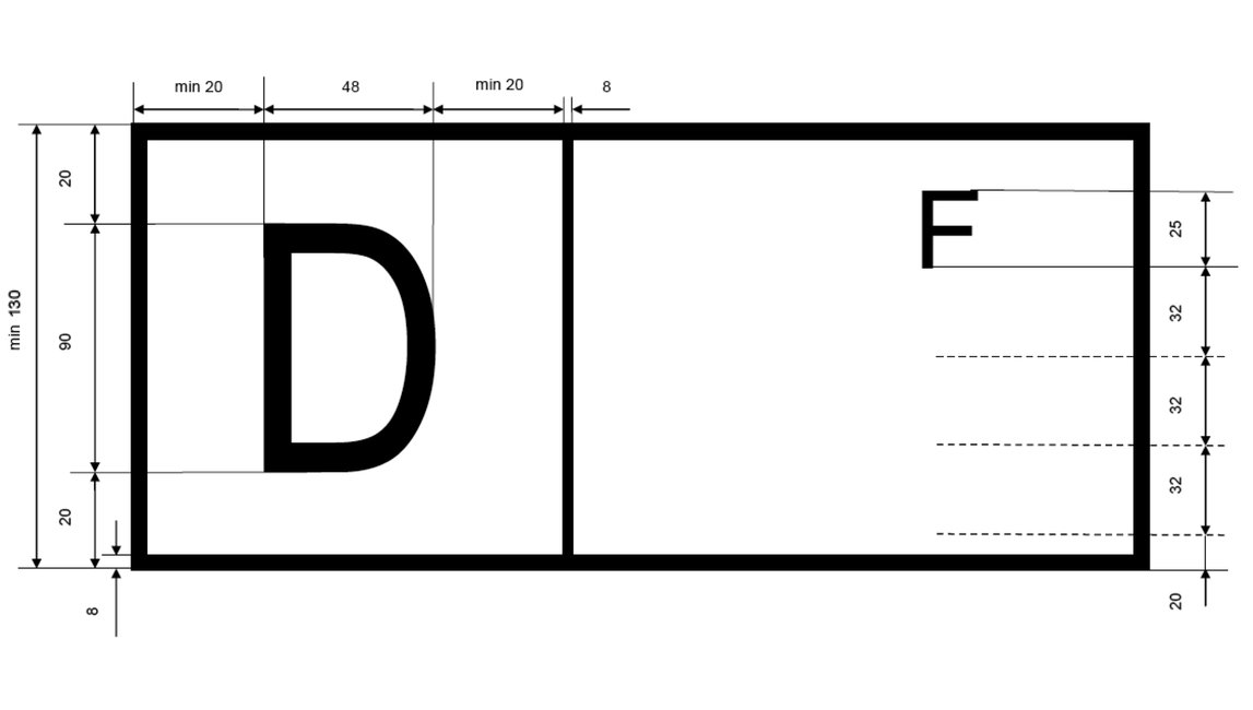
PART 6 — INTEROPERABILITY CODES USED FOR WAGONS (DIGITS 1-2)
|
|
2nd digit 1st digit |
0 |
1 |
2 |
3 |
4 |
5 |
6 |
7 |
8 |
9 |
2nd digit 1st digit |
||
|
|
|
Gauge |
fixed or variable |
fixed |
variable |
fixed |
variable |
fixed |
variable |
fixed |
variable |
fixed or variable |
Gauge |
|
|
0 |
with axles |
Spare |
TSI and/or COTIF wagons (2) [of which keeper is a railway undertaking listed in part 4] |
Not to be used pending further decision |
PPW wagons (variable gauge) |
with axles |
0 |
|||||||
|
1 |
with bogies |
Wagons used by industry |
with bogies |
1 |
||||||||||
|
2 |
with axles |
Spare |
TSI and/or COTIF wagons (2) [of which keeper is a railway undertaking listed in part 4] PPW wagons |
TSI and/or COTIF wagons (2) PPW wagons |
Others TSI and/or/or COTIF wagons (2) PPW wagons |
PPW wagons (fixed gauge) |
with axles |
2 |
||||||
|
3 |
with bogies |
with bogies |
3 |
|||||||||||
|
Non TSI and non COTIF (2) and non PPW |
4 |
with axles (3) |
Service wagons |
Others wagons [of which keeper is a railway undertaking listed in part 4] |
Others wagons |
Others wagons |
Wagons with special numbering for technical characteristics |
with axles (3) |
4 |
|||||
|
8 |
with bogies (3) |
with bogies (3) |
8 |
|||||||||||
|
|
|
Traffic |
Domestic traffic or international traffic by special agreement |
International traffic by special agreement |
Domestic traffic |
International traffic by special agreement |
Domestic traffic |
International traffic by special agreement |
Domestic traffic |
International traffic by special agreement |
Domestic traffic |
Domestic traffic or international traffic by special agreement |
Traffic |
|
|
|
1st digit 2nd digit |
0 |
1 |
2 |
3 |
4 |
5 |
6 |
7 |
8 |
9 |
1st digit 2nd digit |
||
PART 7 — INTERNATIONAL TRAFFIC ABILITY CODES USED FOR HAULED PASSENGER VEHICLES (DIGITS 1-2)
Warning: The conditions between square brackets are transitional and will be deleted with the evolutions of RIC (see general remarks, point 3).
|
|
Domestic traffic |
Domestic traffic or international traffic by special agreement |
PPW |
|||||||
|
2nd digit 1st digit |
0 |
1 |
2 |
3 |
4 |
5 |
6 |
7 |
8 |
9 |
|
5 |
Vehicles for domestic traffic [of which keeper is a RIC railways undertaking listed in part 4] |
Fixed-gauge non air-conditioned vehicles (including car-carrying wagons) [of which keeper is a RIC railways undertaking listed in part 4] |
Gauge-adjustable (1435/1520) non air-conditioned vehicles [of which keeper is a RIC railways undertaking listed in part 4] |
Reserved |
Gauge-adjustable (1435/1672) non air-conditioned vehicles [of which keeper is a RIC railways undertaking listed in part 4] |
Vehicles with special numbering for technical characteristics |
Fixed-gauge vehicles |
Fixed-gauge vehicles |
Gauge-adjustable (1435/1520) vehicles with change of bogies |
Gauge-adjustable (1435/1520) vehicles with gauge-adjustable axles |
|
6 |
Service vehicles not run in revenue-earning service |
Fixed-gauge air-conditioned vehicles [of which keeper is a RIC railways undertaking listed in part 4] |
Gauge-adjustable (1435/1520) air-conditioned vehicles [of which keeper is a RIC railways undertaking listed in part 4] |
Service vehicles not run in revenue-earning service [of which keeper is a RIC railways undertaking listed in part 4] |
Gauge-adjustable (1435/1672) air-conditioned vehicles [of which keeper is a RIC railways undertaking listed in part 4] |
Car-carrying wagons |
Gauge-adjustable vehicles |
|||
|
7 |
Air-conditioned and pressure-tight vehicles [of which keeper is a RIC railways undertaking listed in part 4] |
Reserved |
Reserved |
Pressure-tight fixed-gauge air-conditioned vehicles [of which keeper is a RIVC railways undertaking listed part 4] |
Reserved |
Other vehicles |
Reserved |
Reserved |
Reserved |
Reserved |
PART 8 — TYPES OF TRACTIVE STOCK (DIGITS 1-2)
The first digit is ‘9’.
The second digit is defined by each Member State. It can for example fit with the self-checking digit if this digit is also calculated with the serial number.
If the second digit describes the type of tractive stock, following coding is mandatory:
|
Code |
General vehicle type |
|
0 |
Miscellaneous |
|
1 |
Electric locomotive |
|
2 |
Diesel locomotive |
|
3 |
Electric multiple-unit set (high speed) [power car or trailer] |
|
4 |
Electric multiple-unit set (except high speed) [power car or trailer] |
|
5 |
Diesel multiple-unit set [power car or trailer] |
|
6 |
Specialised trailer |
|
7 |
Electric shunting engine |
|
8 |
Diesel shunting engine |
|
9 |
Special vehicle |
PART 9 — STANDARD NUMERICAL MARKING OF WAGONS (DIGITS 5 TO 8)
This part indicates in tables the numerical marking in 4 figures associated to the main technical characteristics of the wagon.
This part is distributed on a separate medium (electronic file).
PART 10
CODES FOR THE TECHNICAL CHARACTERISTICS OF HAULED PASSENGER STOCK (DIGITS 5-6)
|
|
6th digit 5th digit |
0 |
1 |
2 |
3 |
4 |
|
Reserved |
0 |
Reserved |
Reserved |
Reserved |
Reserved |
Reserved |
|
Vehicles with 1st class seats |
1 |
10 side-corridor compartments or equivalent open-saloon space with centre aisle |
≥ 11 side-corridor compartments or equivalent open-saloon space with centre aisle |
Reserved |
Reserved |
Two or three axles |
|
Vehicles with 2nd class seats |
2 |
10 side-corridor compartments or equivalent open-saloon space with centre aisle |
11 side-corridor compartments or equivalent open-saloon space with centre aisle |
≥ 12 side-corridor compartments or equivalent open-saloon space with centre aisle |
Three axles |
Two axles |
|
Vehicles with 1st or 1st/2nd class seats |
3 |
10 side-corridor compartments or equivalent open-saloon space with centre aisle |
11 side-corridor compartments or equivalent open-saloon space with centre aisle |
≥ 12 side-corridor compartments or equivalent open-saloon space with centre aisle |
Reserved |
Two or three axles |
|
1st or 1st/2nd class couchette cars |
4 |
10 1st/2nd class compartments |
Reserved |
Reserved |
Reserved |
≤ 9 1st/2nd class compartments |
|
2nd class couchette cars |
5 |
10 compartments |
11 compartments |
≥ 12 compartments |
Reserved |
Reserved |
|
Reserved |
6 |
Reserved |
Reserved |
Reserved |
Reserved |
Reserved |
|
Sleeping cars |
7 |
10 compartments |
11 compartments |
12 compartments |
Reserved |
Reserved |
|
Vehicles of special design and vans |
8 |
Driving trailer with seats, all classes, with or without luggage compartment, with driving cab for reversible working |
Vehicles with 1st or 1st/2nd class seats with luggage or mail compartment |
Vehicles with 2nd class seats with luggage or mail compartment |
Reserved |
Vehicles with seats, all classes with specially-fitted areas, e.g. children’s play area |
|
9 |
Mail vans |
Luggage vans with mail compartment |
Luggage vans |
Luggage vans and two or three-axle 2nd class vehicles with seats, with luggage or mail compartment |
Side-corridor luggage vans, with or without compartment under customs seal |
|
|
Note: Fractions of a compartment are not considered. The equivalent accommodation in open saloon cars with centre aisle is obtained by dividing the number of available seats by 6, 8 or 10 depending on the construction of the vehicle. |
||||||
CODES FOR THE TECHNICAL CHARACTERISTICS OF HAULED PASSENGER STOCK (DIGITS 5-6)
|
|
6th digit 5th digit |
5 |
6 |
7 |
8 |
9 |
|
Reserved |
0 |
Reserved |
Reserved |
Reserved |
Reserved |
Reserved |
|
Vehicles with 1st class seats |
1 |
Reserved |
Double-deck coaches |
≥ 7 side-corridor compartments or equivalent open-saloon space with centre aisle |
8 side-corridor compartments or equivalent open-saloon space with centre aisle |
9 side-corridor compartments or equivalent open-saloon space with centre aisle |
|
Vehicles with 2nd class seats |
2 |
Only for OSJD, double-deck coaches |
Double-deck coaches |
Reserved |
≥ 8 side-corridor compartments or equivalent open-saloon space with centre aisle |
9 side-corridor compartments or equivalent open-saloon space with centre aisle |
|
Vehicles with 1st or 1st/2nd class seats |
3 |
Reserved |
Double-deck coaches |
Reserved |
≥ 8 side-corridor compartments or equivalent open-saloon space with centre aisle |
9 side-corridor compartments or equivalent open-saloon space with centre aisle |
|
1st or 1st/2nd class couchette cars |
4 |
Reserved |
Reserved |
Reserved |
Reserved |
≤ 9 1st class compartments |
|
2nd class couchette cars |
5 |
Reserved |
Reserved |
Reserved |
Reserved |
≤ 9 compartments |
|
Reserved |
6 |
Reserved |
Reserved |
Reserved |
Reserved |
Reserved |
|
Sleeping cars |
7 |
> 12 compartments |
Reserved |
Reserved |
Reserved |
Reserved |
|
Vehicles of special design and vans |
8 |
Coaches with seats and couchette cars, all classes, with bar or buffet area |
Double-deck driving coach with seats, all classes, with or without luggage compartment, with driving cab for reversible working |
Dining cars or coaches with bar or buffet area, with luggage compartment |
Dining cars |
Other special coaches (conference, disco, bar, cinema, video, ambulance coaches) |
|
9 |
Two or three-axle luggage vans with mail compartment |
Reserved |
Two or three-axle car-carrying wagons |
Car-carrying wagons |
Service vehicles |
|
|
Note: Fractions of a compartment are not considered. The equivalent accommodation in open saloon cars with centre aisle is obtained by dividing the number of available seats by 6, 8 or 10 depending on the construction of the vehicle. |
||||||
CODES FOR THE GENERAL CHARACTERISTICS OF HAULED PASSENGER STOCK (DIGITS 7-8)
|
Energy supply Maximum speed |
8th digit 7th digit |
0 |
1 |
2 |
3 |
4 |
5 |
6 |
7 |
8 |
9 |
|
< 120 km/h |
0 |
All tensions (*) |
Reserved |
3 000 V~ + 3 000 V = |
1 000 V~ (*) |
Reserved |
1 500 V~ |
Other tensions than 1 000 V, 1 500 V, 3 000 V |
1 500 V~ + 1 500 V = |
3 000 V = |
Reserved |
|
1 |
1 000 V~ + Steam (10) |
1 000 V~ + Steam (10) |
1 000 V~ + Steam (10) |
1 000 V~ + Steam (10) |
1 000 V~ + Steam (10) |
Reserved |
1 500 V~ + 1 500 V = + Steam (10) |
3 000 V = + Steam (10) |
3 000 V = + Steam (10) |
||
|
2 |
Steam (10) |
Steam (10) |
3 000 V~ + 3 000 V = + Steam (10) |
Steam (10) |
3 000 V~ + 3 000 V = + Steam (10) |
Steam (10) |
3 000 V~ + 3 000 V =1 500 V~ + Steam (10) |
1 500 V~ + Steam (10) |
1 500 V~ + Steam (10) |
A (10) |
|
|
121 to 140 km/h |
3 |
All tensions |
Reserved |
1 000 V~ + 3 000 V = |
1 000 V~ |
1 000 V~ + 1 500 V~ + 1 500 V = |
1 500 V~ + 1 500 V = |
3 000 V = |
3 000 V = |
||
|
4 |
All tensions + Steam (10) |
All tensions + Steam (10) |
1 500 V~ + 1 500 V = |
1 000 V~ + Steam (10) |
3 000 V~ + 3 000 V = |
1 500 V~ + 1 500 V = + Steam (10) |
3 000 V = + Steam (10) |
Reserved |
|||
|
5 |
All tensions + Steam (10) |
All tensions + Steam (10) |
1 000 V~ + Steam (10) |
Reserved |
1 500 V~ + Steam (10) |
Other tensions than 1 000 V, 1 500 V, 3 000 V |
1 500 V~ + 1 500 V = + Steam (10) |
Reserved |
Reserved |
||
|
6 |
Steam (10) |
Reserved |
3 000 V~ + 3 000 V = |
Reserved |
3 000 V~ + 3 000 V = |
Reserved |
Steam (10) |
Reserved |
Reserved |
A (10) |
|
|
141 to 160 km/h |
7 |
All tensions (*) |
All tensions |
1 000 V~ (*) |
1 500 V~ + 1 500 V = |
1 000 V~ |
1 500 V~ |
1 500 V~ + 1 500 V = |
3 000 V = |
3 000 V = |
|
|
8 |
All tensions + Steam (10) |
3 000 V~ + 3 000 V = |
Reserved |
1 000 V~ + Steam (10) |
3 000 V~+ 3 000 V = |
Other tensions than 1 000 V, 1 500 V, 3 000 V |
A (10) G (11) |
||||
|
> 160 km/h |
9 |
All tensions |
All tensions + Steam (10) |
1 000 V~ + 1 500 V~ |
1 000 V~ |
1 000 V~ |
Reserved |
1 500 V~ + 1 500 V = |
3 000 V = |
A (10) G (11) |
|
PART 11
CODES FOR THE TECHNICAL CHARACTERISTICS OF SPECIAL VEHICLES (DIGIT 6 TO 8)
Authorised speed for special vehicles (digit 6)
|
Classification |
Self-propelled travelling speed |
||||
|
≥ 100 km/h |
< 100 km/h |
0 km/h |
|||
|
Can be put into a train |
V ≥ 100 km/h |
Self-propelled |
1 |
2 |
|
|
Non self-propelled |
|
|
3 |
||
|
V < 100 km/h and/or restrictions (6) |
Self-propelled |
|
4 |
|
|
|
Non self-propelled |
|
|
5 |
||
|
Cannot be put into a train |
Self-propelled |
|
6 |
|
|
|
Non self-propelled |
|
|
7 |
||
|
Self-propelled rail/road vehicle than can be put into a train (7) |
|
8 |
|
||
|
Self-propelled rail/road vehicle than cannot be put into a train (7) |
|
9 |
|
||
|
Non self-propelled rail/road vehicle (7) |
|
|
0 |
||
TYPE AND SUB-TYPE OF SPECIAL VEHICLE (DIGITS 7-8)
|
7th digit |
8th digit |
Vehicles/machines |
|
1 Infrastructure and superstructure |
1 |
Track laying and renewal train |
|
2 |
Switches and crossing laying equipment |
|
|
3 |
Track rehabilitation train |
|
|
4 |
Ballast cleaning machine |
|
|
5 |
Earthworks machine |
|
|
6 |
||
|
7 |
|
|
|
8 |
|
|
|
9 |
Rail-mounted crane (excl. re-railing) |
|
|
0 |
Other or general |
|
|
2 Track |
1 |
High capacity plain track tamping machine |
|
2 |
Other plain track tamping machines |
|
|
3 |
Tamping machine with stabilisation |
|
|
4 |
Tamping machine for switches and crossings |
|
|
5 |
Ballast plough |
|
|
6 |
Stabilisation machine |
|
|
7 |
Grinding and welding machine |
|
|
8 |
Multi-purpose machine |
|
|
9 |
Track inspection car |
|
|
0 |
Other |
|
|
3 Overhead line |
1 |
Multi-purpose machine |
|
2 |
Rolling and unrolling machine |
|
|
3 |
Mast installation machine |
|
|
4 |
Drum carrier machine |
|
|
5 |
Overhead line tensioning machine |
|
|
6 |
Machine with elevating work platform and machine with scaffold |
|
|
7 |
Cleaning train |
|
|
8 |
Greasing train |
|
|
9 |
Overhead line inspection car |
|
|
0 |
Other |
|
|
4 Structures |
1 |
Deck laying machine |
|
2 |
Bridge inspection platform |
|
|
3 |
Tunnel inspection platform |
|
|
4 |
Gas purification machine |
|
|
5 |
Ventilation machine |
|
|
6 |
Machine with elevating work platform or with scaffold |
|
|
7 |
Tunnel lighting machine |
|
|
8 |
|
|
|
9 |
|
|
|
0 |
Other |
|
|
5 Loading, unloading and various transport |
1 |
Rail loading/unloading and transport machine |
|
2 |
Loading/unloading and transport machine for ballast, gravel, etc. |
|
|
3 |
||
|
4 |
||
|
5 |
Sleeper loading/unloading and transport machine |
|
|
6 |
||
|
7 |
||
|
8 |
Loading/unloading and transport machine for switchgear, etc. |
|
|
9 |
Loading/unloading and transport machine for other materials |
|
|
0 |
Other |
|
|
6 Measuring |
1 |
Earthworks recording car |
|
2 |
Track recording car |
|
|
3 |
Overhead line recording car |
|
|
4 |
Gauge recording car |
|
|
5 |
Signalling recording car |
|
|
6 |
Telecommunications recording car |
|
|
7 |
|
|
|
8 |
|
|
|
9 |
|
|
|
0 |
Other |
|
|
7 Emergency |
1 |
Emergency crane |
|
2 |
Emergency haulage car |
|
|
3 |
Emergency tunnel train |
|
|
4 |
Emergency car |
|
|
5 |
Fire car |
|
|
6 |
Sanitary vehicle |
|
|
7 |
Equipment car |
|
|
8 |
|
|
|
9 |
|
|
|
0 |
Other |
|
|
8 Traction, transport, energy, etc. |
1 |
Tractive units |
|
2 |
||
|
3 |
Transport car (excl. 59) |
|
|
4 |
Power car |
|
|
5 |
Track car / powered car |
|
|
6 |
||
|
7 |
Concreting train |
|
|
8 |
|
|
|
9 |
|
|
|
0 |
Other |
|
|
9 Environment |
1 |
Self-propelled snow plough |
|
2 |
Hauled snow plough |
|
|
3 |
Snow broom |
|
|
4 |
De-icing machine |
|
|
5 |
Weed-killing machine |
|
|
6 |
Rail cleaning machine |
|
|
7 |
|
|
|
8 |
|
|
|
9 |
|
|
|
0 |
Other |
|
|
0 Rail/road |
1 |
Category 1 rail/road machine |
|
2 |
||
|
3 |
Category 2 rail/road machine |
|
|
4 |
||
|
5 |
Category 3 rail/road machine |
|
|
6 |
||
|
7 |
Category 4 rail/road machine |
|
|
8 |
||
|
9 |
|
|
|
0 |
Other |
PART 12 — LETTER MARKING FOR WAGONS EXCLUDING ARTICULATED AND MULTIPLE WAGONS
DEFINITION OF THE CATEGORY AND INDEX LETTERS
1. Important notes
In the attached tables:
|
— |
the information given in meters refers to the inside length of the wagons (lu); |
|
— |
the information given in tonnes (tu) corresponds to the highest load limit shown in the loading table for the wagon in question, this limit being determined in accordance with the procedures laid down. |
2. Index letters with an international value common to all categories
|
q |
pipe for electric heating which can be supplied by all accepted currents |
|
|
pipe and installation for electric heating which can be supplied by all accepted currents |
|
s |
wagons authorised to run under ‘s’ conditions (see Annex B of Rolling Stock TSI) |
|
ss |
wagons authorised to run under ‘ss’ conditions (see Annex B of Rolling Stock TSI) |
3. Index letters with a national value
t, u, v, w, x, y, z
The value of these letters is defined by each Member State.
CATEGORY LETTER: E — OPEN HIGH-SIDED WAGON
|
Reference wagon |
of ordinary type, with side and end tipping, with flat floor with 2 axles: lu ≥ 7,70 m; 25 t ≤ tu ≤ 30 t with 4 axles: lu ≥ 12 m; 50 t ≤ tu ≤ 60 t with 6 axles or more: lu ≥ 12 m; 60 t ≤ tu ≤ 75 t |
|
|
Index letters |
a |
with 4 axles |
|
aa |
with 6 axles or more |
|
|
c |
with floor traps (8) |
|
|
k |
with 2 axles: tu < 20 t with 4 axles: tu < 40 t with 6 axles or more: tu < 50 t |
|
|
kk |
with 2 axles: 20 t ≤ tu < 25 t with 4 axles: 40 t ≤ tu < 50 t with 6 axles or more: 50 t ≤ tu < 60 t |
|
|
l |
without side tipping |
|
|
ll |
without floor traps (9) |
|
|
m |
with 2 axles: lu < 7,70 m with 4 axles or more: lu < 12 m |
|
|
mm |
with 4 axles or more: lu >12 m (9) |
|
|
n |
with 2 axles: tu > 30 t with 4 axles: tu > 60 t with 6 axles or more: tu > 75 t |
|
|
o |
without end tipping |
|
|
p |
with station for brakeman (9) |
|
CATEGORY LETTER: F — OPEN HIGH-SIDED WAGON
|
Reference wagon |
Of special type with 2 axles: 25 t ≤ tu ≤ 30 t with 3 axles: 25 t ≤ tu ≤ 40 t with 4 axles: 50 t ≤ tu ≤ 60 t with 6 axles or more: 60 t ≤ tu ≤ 75 t |
|
|
Index letters |
a |
with 4 axles |
|
aa |
with 6 axles or more |
|
|
b |
high capacity with axles (volume > 45 m3) |
|
|
c |
with controlled gravity unloading, on both sides, alternately, at the top (10) |
|
|
cc |
with controlled gravity unloading, on both sides, alternately, at the bottom (10) |
|
|
f |
suitable for traffic with Great Britain |
|
|
ff |
suitable for traffic with Great Britain (by tunnel exclusively) |
|
|
fff |
suitable for traffic with Great Britain (by train-ferry exclusively) |
|
|
k |
with 2 or 3 axles: tu < 20 t with 4 axles: tu < 40 t with 6 axles or more: tu < 50 t |
|
|
kk |
with 2 or 3 axles: 20 t ≤ tu < 25 t with 4 axles: 40 t ≤ tu < 50t with 6 axles or more: 50 t ≤ tu < 60 t |
|
|
l |
with bulk gravity unloading, on both sides, simultaneously, at the top (10) |
|
|
ll |
with bulk gravity unloading, on both sides, simultaneously, at the bottom (10) |
|
|
n |
with 2 axles: tu > 30 t with 3 axles or more: tu > 40 t with 4 axles: tu > 60 t with 6 axles or more: tu > 75 t |
|
|
o |
with axial bulk gravity unloading, at the top (10) |
|
|
oo |
with axial bulk gravity unloading, at the bottom (10) |
|
|
p |
with axial controlled gravity unloading, at the top (10) |
|
|
pp |
with axial controlled gravity unloading, at the bottom (10) |
|
|
ppp |
with station for brakeman (11) |
|
CATEGORY LETTER: G — COVERED WAGON
|
Reference wagon |
Of ordinary type with at least 8 ventilation apertures with 2 axles: 9 m ≤ lu < 12 m; 25 t ≤ tu ≤ 30 t with 4 axles: 15 m ≤ lu < 18 m; 50 t ≤ tu ≤ 60 t with 6 axles or more: 15 m ≤ lu < 18 m; 60 t ≤ tu ≤ 75 t |
||||
|
Index letters |
a |
with 4 axles |
|||
|
aa |
with 6 axles or more |
||||
|
b |
high capacity:
|
||||
|
bb |
with 4 axles: lu > 18 m (12) |
||||
|
g |
for grain |
||||
|
h |
for fruits and vegetables (13) |
||||
|
k |
with 2 axles: tu < 20 t with 4 axles: tu < 40t with 6 axles or more: tu < 50 t |
||||
|
kk |
with 2 axles: 20 t ≤ tu < 25 t with 4 axles: 40 t ≤ tu < 50 t with 6 axles or more: 50 t ≤ tu < 60 t |
||||
|
l |
with less than 8 ventilation apertures |
||||
|
ll |
with enlarged doors apertures (12) |
||||
|
m |
with 2 axles: lu < 9 m with 4 axles or more: lu < 15 m |
||||
|
n |
with 2 axles: tu > 30 t with 4 axles: tu > 60 t with 6 axles or more: tu > 75 t |
||||
|
o |
with 2 axles: lu < 12 m and payload capacity ≥ 70 m3 |
||||
|
p |
with station for brakeman (12) |
||||
CATEGORY LETTER: H — COVERED WAGON
|
Reference wagon |
of special type with 2 axles: 9 m ≤ lu ≤ 12 m; 25 t ≤ tu ≤ 28 t with 4 axles: 15 m ≤ lu < 18 m; 50 t ≤ tu ≤ 60 t with 6 axles or more: 15 m ≤ lu < 18 m; 60 t ≤ tu ≤ 75 t |
|
|
Index letters |
a |
with 4 axles |
|
aa |
with 6 axles or more |
|
|
b |
with 2 axles: 12 m ≤ lu ≤ 14 m and payload capacity ≥ 70 m3 (14) with 4 axles or more: 18 m ≤ lu < 22 m |
|
|
bb |
with 2 axles: lu ≥ 14m with 4 axles or more: lu ≥ 22 m |
|
|
c |
with end doors |
|
|
cc |
with end doors and fitted internally for the transport of motor cars |
|
|
d |
with floor traps |
|
|
dd |
with tipping body (15) |
|
|
e |
with 2 floors |
|
|
ee |
with 3 floors or more |
|
|
f |
suitable for traffic with Great Britain (14) |
|
|
ff |
suitable for traffic with Great Britain (by tunnel exclusively) |
|
|
fff |
suitable for traffic with Great Britain (by train-ferry exclusively) (14) |
|
|
g |
for grain |
|
|
gg |
for cement (15) |
|
|
h |
for fruits and vegetables (16) |
|
|
hh |
for mineral fertilizer (15) |
|
|
i |
with opening or shunt walls |
|
|
ii |
with very robust opening or shunt walls (17) |
|
|
k |
with 2 axles: tu < 20 t with 4 axles: tu < 40 t with 6 axles or more: tu < 50 t |
|
|
kk |
with 2 axles: 20 t ≤ tu < 25 t with 4 axles: 40 t ≤ tu < 50 t with 6 axles or more: 50 t ≤ tu < 60 t |
|
|
l |
with movable partitions (18) |
|
|
ll |
with lockable movable partitions (15) |
|
|
m |
with 2 axles: lu < 9 m with 4 axles or more: lu < 15 m |
|
|
mm |
with 4 axles or more: lu > 18 m (15) |
|
|
n |
with 2 axles: tu > 28 t with 4 axles: tu < 60 t with 6 axles or more: tu > 75 t |
|
|
o |
with 2 axles: lu 12 m < 14 m et volume utile ≥ 70 m3 |
|
|
p |
with station for brakeman (15) |
|
CATEGORY LETTER: I — TEMPERATURE-CONTROLLED WAGON
|
Reference wagon |
refrigerator wagon with class IN thermal insulation, with motor-driven ventilation, with gratings and ice bunker ≥ 3,5 m3 with 2 axles: 19 m2 ≤ floor area < 22 m2; 15 t ≤ tu ≤ 25 t with 4 axles: floor area ≥ 39 m2; 30 t ≤ tu ≤ 40 t |
|
|
Index letters |
a |
with 4 axles |
|
b |
with 2 axles and large floor area: 22 m2 ≤ floor area ≤ 27 m2 |
|
|
bb |
with 2 axles and very large floor area: floor area > 27 m2 |
|
|
c |
with meat hooks |
|
|
d |
for fish |
|
|
e |
with electric ventilation |
|
|
f |
suitable for traffic with Great Britain |
|
|
ff |
suitable for traffic with Great Britain (by tunnel exclusively) |
|
|
fff |
suitable for traffic with Great Britain (by train-ferry exclusively) |
|
|
g |
||
|
gg |
refrigerator with liquefied gas (19) |
|
|
h |
with class IR thermal insulation |
|
|
i |
mechanically refrigerated by the machinery of an accompanying technical wagon (19) (20) (21) |
|
|
ii |
||
|
k |
with 2 axles: tu > 15 t with 4 axles: tu < 30 t |
|
|
l |
||
|
m |
with 2 axles: floor area < 19 m2 with 4 axles: floor area < 39 m2 |
|
|
mm |
with 4 axles: floor area ≥ 39 m2 (23) |
|
|
n |
with 2 axles: tu > 25 t with 4 axles; tu > 40 t |
|
|
o |
with ice bunkers of capacity less than 3,5 m3 (22) |
|
|
p |
without gratings |
|
CATEGORY LETTER: K — 2-AXLE FLAT WAGON
|
Reference wagon |
Of ordinary type with drop sides and short stanchions lu ≥ 12 m; 25 t ≤ tu ≤ 30 t |
|
|
Index letters |
b |
with long stanchions |
|
g |
fitted for the transport of containers (24) |
|
|
i |
with removable cover and non-removable ends (25) |
|
|
j |
with shock-absorbing device |
|
|
k |
tu < 20 t |
|
|
kk |
20 t ≤ tu < 25 t |
|
|
l |
without stanchions |
|
|
m |
9 m ≤ lu < 12 m |
|
|
mm |
lu < 9 m |
|
|
n |
tu > 30 t |
|
|
o |
with non-removable sides |
|
|
p |
without sides (25) |
|
|
pp |
with removable sides |
|
CATEGORY LETTER: L — 2-AXLE FLAT WAGON
|
Reference wagon |
of special type lu ≥ 12 m; 25 t ≤ tu ≤ 30 t |
|
|
Index letters |
b |
with special fittings for securing purposes for medium-sized containers (pa) (26) |
|
c |
with swivelling bolster (26) |
|
|
d |
fitted out for the transport of motor cars, without deck (26) |
|
|
e |
with decks for the transport of motor cars (26) |
|
|
f |
suitable for traffic with Great Britain |
|
|
ff |
suitable for traffic with Great Britain (by tunnel exclusively) |
|
|
fff |
suitable for traffic with Great Britain (by train-ferry exclusively) |
|
|
g |
fitted for the transport of containers (except pa) (26) (27) |
|
|
h |
fitted out for the transport of steel coils, eye to side (26) (28) |
|
|
hh |
fitted out for the transport of steel coils, eye to sky (26) (28) |
|
|
i |
with removable cover and non-removable ends (26) |
|
|
ii |
with very robust removable metallic cover (29) and non-removable ends (26) |
|
|
j |
with shock-absorbing device |
|
|
k |
tu < 20 t |
|
|
kk |
20 t ≤ tu < 25 t |
|
|
l |
without stanchions (26) |
|
|
m |
9 m ≤ lu < 12 m |
|
|
mm |
lu < 9 m |
|
|
n |
tu > 30 t |
|
|
p |
without sides (26) |
|
CATEGORY LETTER: O — MIXED FLAT AND OPEN HIGH-SIDED WAGON
|
Reference wagon |
of ordinary type with 2 or 3 axles, with drop sides or ends and stanchions with 2 axles: lu ≥ 12 m; 25 t ≤ tu ≤ 30 t with 3 axles: lu ≥ 12 m; 25 t ≤ tu ≤ 40 t |
|
|
Index letters |
a |
with 3 axles |
|
f |
suitable for traffic with Great Britain |
|
|
ff |
suitable for traffic with Great Britain (by tunnel exclusively) |
|
|
fff |
suitable for traffic with Great Britain (by train-ferry exclusively) |
|
|
k |
tu < 20 t |
|
|
kk |
20 t ≤ tu < 25 t |
|
|
l |
without stanchions |
|
|
m |
9 m ≤ lu < 12 m |
|
|
mm |
lu < 9 m |
|
|
n |
with 2 axles: tu > 30 t with 3 axles: tu > 40 t |
|
CATEGORY LETTER: R — FLAT BOGIES WAGON
|
Reference wagon |
of ordinary type with drop ends and stanchions 18 m ≤ lu < 22 m; 50 t ≤ tu ≤ 60 t |
|
|
Index letters |
b |
lu ≥ 22 m |
|
e |
with drop sides |
|
|
g |
fitted for the transport of containers (30) |
|
|
h |
fitted out for the transport of steel coils, eye to side (31) |
|
|
hh |
fitted out for the transport of steel coils, eye to sky (31) |
|
|
i |
with removable cover and non-removable ends (32) |
|
|
j |
with shock-absorbing device |
|
|
k |
tu < 40 t |
|
|
kk |
40 t ≤ tu < 50 t |
|
|
l |
without stanchions |
|
|
m |
15 m ≤ lu < 18 m |
|
|
mm |
lu < 15 m |
|
|
n |
tu > 60 t |
|
|
o |
with non-removable ends less than 2 m in height |
|
|
oo |
with non-removable ends, 2 m or more in height (32) |
|
|
p |
without drop ends (32) |
|
|
pp |
with removable sides |
|
CATEGORY LETTER: S — FLAT BOGIES WAGON
|
Reference wagon |
of special type with 4 axles: lu ≥ 18 m; 50 t ≤ tu ≤ 60 t with 6 axles or more: lu ≥ 22 m; 60 t ≤ tu ≤ 75 t |
|
|
Index letters |
a |
with 6 axles (2 bogies of 3 axles) |
|
aa |
with 8 axles or more |
|
|
aaa |
with 4 axles (2 bogies of 2 axles) (33) |
|
|
b |
with special fittings for securing purposes for medium-sized containers (pa) (34) |
|
|
c |
with swivelling bolster (34) |
|
|
d |
fitted out for the transport of motor cars, without deck (34) (35) |
|
|
e |
with decks for the transport of motor cars (34) |
|
|
f |
suitable for traffic with Great Britain |
|
|
ff |
suitable for traffic with Great Britain (by tunnel exclusively) |
|
|
fff |
suitable for traffic with Great Britain (by train-ferry exclusively) |
|
|
g |
fitted for the transport of containers, total loading length ≤ 60’ (except pa) (34) (35) (36) |
|
|
gg |
fitted for the transport of containers, total loading length > 60’ (except pa) (34) (35) (36) |
|
|
h |
fitted out for the transport of steel coils, eye to side (34) (37) |
|
|
hh |
fitted out for the transport of steel coils, eye to sky (34) (37) |
|
|
i |
with removable cover and non-removable ends (34) |
|
|
ii |
with very robust removable metallic cover (38) and non-removable ends (34) |
|
|
j |
with shock-absorbing device |
|
|
k |
with 4 axles: tu < 40 t with 6 axles or more: tu < 50 t |
|
|
kk |
with 4 axles: 40 t ≤ tu < 50 t with 6 axles or more: 50 t ≤ tu < 60 t |
|
|
l |
without stanchions (34) |
|
|
m |
with 4 axles: 15 m ≤ lu < 18 m; with 6 axles or more: 18 m ≤ lu < 22 m |
|
|
mm |
with 4 axles: lu < 15 m with 6 axles or more: lu < 18 m |
|
|
mmm |
with 4 axles : lu ≥ 22 m (33) |
|
|
n |
with 4 axles: tu > 60 t with 6 axles or more: tu > 75 t |
|
|
p |
without sides (34) |
|
CATEGORY LETTER: T — WAGON WITH OPENING ROOF
|
Reference wagon |
with 2 axles: 9 m ≤ lu < 12 m; 25 t ≤ tu ≤ 30 t with 4 axles: 15 m ≤ lu < 18 m; 50 t ≤ tu ≤ 60 t with 6 axles or more: 15 m ≤ lu < 18 m; 60 t ≤ tu ≤ 75 t |
|
|
Index letters |
a |
with 4 axles |
|
aa |
with 6 axles or more |
|
|
b |
high capacity: with 2 axles: lu ≥ 12 m |
|
|
c |
with end doors |
|
|
d |
with controlled gravity unloading, on both sides, alternately, at the top (39) (40) (41) |
|
|
dd |
with controlled gravity unloading, on both sides, alternately, at the bottom (39) (40) (41) |
|
|
e |
with unobstructed height of the doors > 1,90 m (39) (40) (41) |
|
|
f |
suitable for traffic with Great Britain |
|
|
ff |
suitable for traffic with Great Britain (by tunnel exclusively) |
|
|
fff |
suitable for traffic with Great Britain (by train-ferry exclusively) |
|
|
g |
for grain |
|
|
h |
fitted out for the transport of steel coils, eye to side |
|
|
hh |
fitted out for the transport of steel coils, eye to sky |
|
|
i |
with opening walls (39) |
|
|
j |
with shock-absorbing device |
|
|
k |
with 2 axles: tu < 20 t with 4 axles: tu < 40 t with 6 axles or more: tu < 50 t |
|
|
kk |
with 2 axles: 20 t ≤ tu < 25 t with 4 axles: 40 t ≤ tu < 50 t with 6 axles or more: 50 t ≤ tu < 60 t |
|
|
l |
with bulk gravity unloading, on both sides, simultaneously, at the top (39) (40) (41) |
|
|
ll |
with bulk gravity unloading, on both sides, simultaneously, at the bottom (39) (40) (41) |
|
|
m |
with 2 axles: lu < 9 m with 4 axles or more: lu < 15 m (40) |
|
|
n |
with 2 axles: tu > 30 t with 4 axles: tu > 60 t with 6 axles or more: tu > 75 t |
|
|
o |
with axial bulk gravity unloading, at the top (39) (40) (41) |
|
|
oo |
with axial bulk gravity unloading, at the bottom (39) (40) (41) |
|
|
p |
with axial controlled gravity unloading, at the top (39) (40) (41) |
|
|
pp |
with axial controlled gravity unloading, at the bottom (39) (40) (41) |
|
CATEGORY LETTER: U — SPECIAL WAGONS
|
Reference wagon |
other than those in categories F, H, L, S ou Z with 2 axles: 25 t ≤ tu ≤ 30 t with 3 axles: 25 t ≤ tu ≤ 40 t with 4 axles: 50 t ≤ tu ≤ 60t with 6 axles or more: 60 t ≤ tu ≤ 75 t |
|
|
Index letters |
a |
with 4 axles |
|
aa |
with 6 axles or more |
|
|
c |
with unloading under pressure |
|
|
d |
with controlled gravity unloading, on both sides, alternately, at the top (42) |
|
|
dd |
with controlled gravity unloading, on both sides, alternately, at the bottom (42) |
|
|
f |
suitable for traffic with Great Britain |
|
|
ff |
suitable for traffic with Great Britain (by tunnel exclusively) |
|
|
fff |
suitable for traffic with Great Britain (by train-ferry exclusively) |
|
|
g |
for grain |
|
|
i |
fitted out for the transport objects which should exceed the gauge if they were loaded on ordinary wagons (43) (44) |
|
|
k |
with 2 or 3 axles: tu < 20 t with 4 axles: tu < 40 t with 6 axles or more: tu < 50 t |
|
|
kk |
with 2 or 3 axles: 20 t ≤ tu < 25 t with 4 axles: 40 t ≤ tu < 50 t with 6 axles or more: 50 t ≤ tu < 60 t |
|
|
l |
with bulk gravity unloading, on both sides, simultaneously, at the top (42) |
|
|
ll |
with bulk gravity unloading, on both sides, simultaneously, at the bottom (42) |
|
|
n |
with 2 axles: tu > 30 t with 3 axles: tu > 40 t with 4 axles: tu > 60 t with 6 axles or more: tu > 75 t (44) |
|
|
o |
with axial bulk gravity unloading, at the top (42) |
|
|
oo |
with axial bulk gravity unloading, at the bottom (42) |
|
|
p |
with axial bulk gravity unloading, at the top (42) |
|
|
pp |
with axial bulk gravity unloading, at the bottom (42) |
|
CATEGORY LETTER: Z — TANK WAGON
|
Reference wagon |
with metal shell, for the transport of liquids or gases with 2 axles: 25 t ≤ lu ≤ 30 t with 3 axles: 25 t ≤ tu ≤ 40 t with 4 axles: 50 t ≤ tu ≤ 60 t with 6 axles or more: 60 t ≤ tu ≤ 75 t |
|
|
Index letters |
a |
with 4 axles |
|
aa |
with 6 axles or more |
|
|
b |
for oil products (45) |
|
|
c |
with unloading under pressure (46) |
|
|
d |
for food and chemical products (45) |
|
|
e |
fitted with heating devices |
|
|
f |
suitable for traffic with Great Britain |
|
|
ff |
suitable for traffic with Great Britain (by tunnel exclusively) |
|
|
fff |
suitable for traffic with Great Britain (by train-ferry exclusively) |
|
|
g |
for the transport of gases under pressure, liquefied or dissolved under pressure (46) |
|
|
i |
tank of non-metallic material |
|
|
j |
with shock-absorbing device |
|
|
k |
with 2 or 3 axles: tu < 20 t with 4 axles: tu < 40 t with 6 axles or more: tu < 50 t |
|
|
kk |
with 2 or 3 axles: 20 t ≤ tu < 25 t with 4 axles: 40 t ≤ tu < 50 t with 6 axles or more: 50 t ≤ tu < 60 t |
|
|
n |
with 2 axles: tu > 30 t with 3 axles: tu > 40 t with 4 axles tu > 60 t with 6 axles or more: tu > 75 t |
|
|
p |
with station for brakeman (45) |
|
LETTER MARKING FOR WAGONS FOR ARTICULATED AND MULTIPLE WAGONS
DEFINITION OF THE CATEGORY AND INDEX LETTERS
1. Important notes
In the attached tables, the information given in meters refers to the inside length of the wagons (lu).
2. Index letters with an international value common to all categories
|
q |
pipe for electric heating which can be supplied by all accepted currents |
|
|
pipe and installation for electric heating which can be supplied by all accepted currents |
|
s |
wagons authorised to run under ‘s’ conditions (see annex B of rolling stock STI) |
|
ss |
wagons authorised to run under ‘ss’ conditions (see annex B of rolling stock STI) |
3. Index letters with a national value
t, u, v, w, x, y, z
The value of these letters is defined by each Member State.
CATEGORY LETTER: F — OPEN HIGH-SIDED WAGON
|
Reference wagon |
Articulated or multiple wagon with axles, with 2 units 22 m ≤ lu < 27 m |
|
|
Index letters |
a |
with bogies |
|
c |
with controlled gravity unloading, on both sides, alternately, at the top (47) |
|
|
cc |
with controlled gravity unloading, on both sides, alternately, at the bottom (47) |
|
|
E |
with 3 units |
|
|
ee |
with 4 units or more |
|
|
f |
suitable for traffic with Great Britain |
|
|
ff |
suitable for traffic with Great Britain (by tunnel exclusively) |
|
|
fff |
suitable for traffic with Great Britain (by train-ferry exclusively) |
|
|
l |
with bulk gravity unloading, on both sides, simultaneously, at the top (47) |
|
|
ll |
with bulk gravity unloading, on both sides, simultaneously, at the bottom (47) |
|
|
m |
with 2 units: lu ≥ 27 m |
|
|
mm |
with 2 units: lu < 22 m |
|
|
o |
with axial bulk gravity unloading, at the top (47) |
|
|
oo |
with axial bulk gravity unloading, at the bottom (47) |
|
|
p |
with axial controlled gravity unloading, at the top (47) |
|
|
pp |
with axial controlled gravity unloading, at the bottom (47) |
|
|
r |
articulated wagon |
|
|
rr |
multiple wagon |
|
CATEGORY LETTER: H — COVERED WAGON
|
Reference wagon |
articulated or multiple wagon with axles, with 2 units 22 m ≤ lu < 27 m |
|
|
Index letters |
a |
with bogies |
|
c |
with end doors |
|
|
cc |
with end doors and fitted internally for the transport of motor cars |
|
|
d |
with floor traps |
|
|
e |
with 3 units |
|
|
ee |
with 4 units or more |
|
|
f |
suitable for traffic with Great Britain |
|
|
ff |
suitable for traffic with Great Britain (by tunnel exclusively) |
|
|
fff |
suitable for traffic with Great Britain (by train-ferry exclusively) |
|
|
g |
for grain |
|
|
h |
for fruits and vegetables (48) |
|
|
i |
with opening or shunt walls |
|
|
ii |
with very robust opening or shunt walls (49) |
|
|
l |
with movable partitions (50) |
|
|
ll |
with lockable movable partitions (50) |
|
|
m |
with 2 units: lu ≥ 27 m |
|
|
mm |
with 2 units: lu < 22 m |
|
|
r |
articulated wagon |
|
|
rr |
multiple wagon |
|
CATEGORY LETTER: I — TEMPERATURE CONTROLLED WAGON
|
Reference wagon |
refrigerator wagon with class IN thermal insulation, with motor-driven ventilation, with gratings and ice bunker ≥ 3,5 m3 articulated or multiple wagon with axles, with 2 units 22 m ≤ lu < 27 m |
|
|
Index letters |
a |
with bogies |
|
c |
with meat hooks |
|
|
d |
for fish |
|
|
e |
with electric ventilation |
|
|
ee |
with 4 units or more |
|
|
f |
suitable for traffic with Great Britain |
|
|
ff |
suitable for traffic with Great Britain (by tunnel exclusively) |
|
|
fff |
suitable for traffic with Great Britain (by train-ferry exclusively) |
|
|
g |
with mechanical refrigeration (51) |
|
|
gg |
refrigerator with liquefied gas (51) |
|
|
h |
with class IR thermal insulation |
|
|
i |
mechanically refrigerated by the machinery of an accompanying technical wagon (51) (52) |
|
|
ii |
||
|
l |
||
|
m |
with 2 units: lu ≥ 27 m |
|
|
mm |
with 2 units: lu < 22 m |
|
|
o |
with ice bunkers of capacity less than 3,5 m3 (53) |
|
|
oo |
with 3 units |
|
|
p |
without gratings |
|
|
r |
articulated wagon |
|
|
rr |
multiple wagon |
|
CATEGORY LETTER: L — FLAT WAGON WITH SEPARATE AXLES
|
Reference wagon |
articulated or multiple wagon with 2 units 22 m ≤ lu < 27 m |
|
|
Index letters |
a |
articulated wagon |
|
aa |
multiple wagon |
|
|
b |
with special fittings for securing purposes for medium-sized containers (pa) (54) |
|
|
c |
with swivelling bolster (54) |
|
|
d |
fitted out for the transport of motor cars, without deck (54) |
|
|
e |
with decks for the transport of motor cars (54) |
|
|
f |
suitable for traffic with Great Britain |
|
|
ff |
suitable for traffic with Great Britain (by tunnel exclusively) |
|
|
fff |
suitable for traffic with Great Britain (by train-ferry exclusively) |
|
|
g |
||
|
h |
fitted out for the transport of steel coils, eye to side (54) (56) |
|
|
hh |
fitted out for the transport of steel coils, eye to sky (54) (56) |
|
|
i |
with removable cover and non-removable ends (54) |
|
|
ii |
with very robust removable metallic cover (57) and non-removable ends (54) |
|
|
j |
with shock-absorbing device |
|
|
l |
without stanchions (54) |
|
|
m |
with 2 units: 18 m ≤ lu < 22 m |
|
|
mm |
with 2 units: lu < 18 m |
|
|
o |
with 3 units |
|
|
oo |
with 4 units or more |
|
|
p |
without sides (54) |
|
|
r |
with 2 units: lu ≥ 27 m |
|
CATEGORY LETTER: S — FLAT BOGIE WAGON
|
Reference wagon |
articulated or multiple wagon with 2 units 22 m ≤ lu < 27 m |
|
|
Index letters |
b |
with special fittings for securing purposes for medium-sized containers (pa) (58) |
|
c |
with swivelling bolster (58) |
|
|
d |
fitted out for the transport of motor cars, without deck (58) (59) |
|
|
e |
with decks for the transport of motor cars (58) |
|
|
f |
suitable for traffic with Great Britain |
|
|
ff |
suitable for traffic with Great Britain (by tunnel exclusively) |
|
|
fff |
suitable for traffic with Great Britain (by train-ferry exclusively) |
|
|
g |
fitted for the transport of containers, total loading length ≤ 60’ (except pa) (58) (59) (60) |
|
|
gg |
fitted for the transport of containers, total loading length > 60’ (except pa) (58) (59) (60) |
|
|
h |
fitted out for the transport of steel coils, eye to side (58) (61) |
|
|
hh |
fitted out for the transport of steel coils, eye to sky (58) (61) |
|
|
i |
with removable cover and non-removable ends (58) |
|
|
ii |
with very robust removable metallic cover (58) and non-removable ends (62) |
|
|
j |
with shock-absorbing device |
|
|
l |
without stanchions (58) |
|
|
m |
with 2 units: lu ≥ 27 m |
|
|
mm |
with 2 units: lu < 22 m |
|
|
o |
with 3 units |
|
|
oo |
with 4 units or more |
|
|
p |
without sides (58) |
|
|
r |
articulated wagon |
|
|
rr |
multiple wagon |
|
CATEGORY LETTER: T — WAGON WITH OPENING ROOF
|
Reference wagon |
articulated or multiple wagon with axles, with 2 units 22 m ≤ lu < 27 m |
|
|
Index letters |
a |
with bogies |
|
b |
with unobstructed height of doors > 1,90 m (63) |
|
|
c |
with end doors |
|
|
d |
with controlled gravity unloading, on both sides, alternately, at the top (64) |
|
|
dd |
with controlled gravity unloading, on both sides, alternately, at the bottom (63) (64) |
|
|
e |
with 3 units |
|
|
ee |
with 4 units or more |
|
|
f |
suitable for traffic with Great Britain |
|
|
ff |
suitable for traffic with Great Britain (by tunnel exclusively) |
|
|
fff |
suitable for traffic with Great Britain (by train-ferry exclusively) |
|
|
g |
for grain |
|
|
h |
fitted out for the transport of steel coils, eye to side |
|
|
hh |
fitted out for the transport of steel coils, eye to sky |
|
|
i |
with opening walls (63) |
|
|
j |
with shock-absorbing device |
|
|
l |
with bulk gravity unloading, on both sides, simultaneously, at the top (63) (64) |
|
|
ll |
with bulk gravity unloading, on both sides, simultaneously, at the bottom (63) (64) |
|
|
m |
with 2 units: lu ≥ 27 m |
|
|
mm |
with 2 units: lu < 22 m |
|
|
o |
||
|
oo |
||
|
p |
with axial controlled gravity unloading, at the top (63) (64) |
|
|
pp |
with axial controlled gravity unloading, at the bottom (63) (64) |
|
|
r |
articulated wagon |
|
|
rr |
multiple wagon |
|
CATEGORY LETTER: U — SPECIAL WAGONS
|
Reference wagon |
articulated or multiple wagon, with axles, with 2 units 22 m ≤ lu < 27 m |
|
|
Index letters |
a |
with bogies |
|
e |
with 3 units |
|
|
ee |
with 4 units or more |
|
|
c |
with unloading under pressure |
|
|
d |
with controlled gravity unloading, on both sides, alternately, at the top (65) |
|
|
dd |
with controlled gravity unloading, on both sides, alternately, at the bottom (65) |
|
|
f |
suitable for traffic with Great Britain |
|
|
ff |
suitable for traffic with Great Britain (by tunnel exclusively) |
|
|
fff |
suitable for traffic with Great Britain (by train-ferry exclusively) |
|
|
g |
for grain |
|
|
i |
fitted out for the transport objects which should exceed the gauge if they were loaded on ordinary wagons (66) |
|
|
l |
with bulk gravity unloading, on both sides, simultaneously, at the top (66) |
|
|
ll |
with bulk gravity unloading, on both sides, simultaneously, at the bottom (66) |
|
|
m |
with 2 units: lu ≥ 27 m |
|
|
mm |
with 2 units: lu < 22 m |
|
|
o |
with axial bulk gravity unloading, at the top (66) |
|
|
oo |
||
|
p |
with axial controlled gravity unloading, at the top (65) |
|
|
pp |
with axial controlled gravity unloading, at the bottom (65) |
|
|
r |
articulated wagon |
|
|
rr |
multiple wagon |
|
CATEGORY LETTER: Z — TANK WAGON
|
Reference wagon |
with metal shell, for the transport of liquids or gases articulated or multiple wagon with axles, with 2 units 22 m ≤ lu < 27 m |
|
|
Index letters |
a |
with bogies |
|
c |
with unloading under pressure (67) |
|
|
e |
fitted with heating devices |
|
|
f |
suitable for traffic with Great Britain |
|
|
ff |
suitable for traffic with Great Britain (by tunnel exclusively) |
|
|
fff |
suitable for traffic with Great Britain (by train-ferry exclusively) |
|
|
g |
for the transport of gases under pressure, liquefied or dissolved under pressure (67) |
|
|
i |
tank of non-metallic material |
|
|
j |
with shock-absorbing device |
|
|
m |
with 2 units: lu ≥ 27 m |
|
|
mm |
with 2 units: lu < 22 m |
|
|
o |
with 3 units |
|
|
oo |
with 4 units or more |
|
|
r |
articulated wagon |
|
|
rr |
multiple wagon |
|
PART 13 — LETTER MARKING FOR HAULED PASSENGER STOCK
Serial letters with an international value:
|
A |
1st class coach with seats |
|
B |
2nd class coach with seats |
|
AB |
1st/2nd class coach with seats |
|
WL |
Sleeping-car with serial letter A, B or AB depending on the type of accommodation offered. The serial letters for sleeping-car with ‘special’ compartments are supplemented with index-letter ‘S’ |
|
WR |
Dining-car |
|
R |
Coach with dining-car, buffet or bar compartment (serial-letter used in addition) |
|
D |
Van |
|
DD |
Open, 2-tier car-carrier van |
|
Post |
Mail van |
|
AS SR WG |
Bar coach with dancing facilities |
|
WSP |
Pullman coach |
|
Le |
Open 2-axle 2-tier car-carrier wagon |
|
Leq |
Open 2-axle 2-tier car-carrier wagon fitted with train supply cable |
|
Laeq |
Open 3-axle 2-tier car-carrier wagon fitted with train supply cable |
Index letters with an international value:
|
b h |
Coach fitted out to carry disabled passengers |
|
c |
Compartments convertible into couchette accommodation |
|
d v |
Vehicle fitted to receive bicycles |
|
ee z |
Vehicle fitted with central power supply |
|
f |
Vehicle fitted with driver’s cab (driving trailer) |
|
p t |
Centre-aisle coach with seats |
|
m |
Vehicle over 24,5 m in length |
|
s |
Centre-aisle in vans and coaches with luggage compartment |
The number of compartments is shown in the form of an index (for example: Bc9)
Serial letters and index letters with a national value
The others serial letters and index letters have a national value, defined by each Member State.
PART 14 — LETTER MARKING FOR SPECIAL VEHICLES
This marking is indicated in document EN 14033-1 ‘Railway applications — Track — Technical requirements for railbound construction and maintenance machines — Part 1: Running of railbound machines’.
(1) For tractive rolling stock, the number has to be unique in a given country with 6 digits.
(2) For special vehicles, the number has to be unique in a given country with the first digit and the 5 last digits of the technical characteristics and serial number.
(3) A vehicle keeper is the person, who being the owner of having the right to dispose of it, exploits a vehicle economically in a permanent manner as a means of transport and is registered as such in the Rolling Stock Register.
(4) For NMBS/SNCB, the use of an encircled single letter B can be continued.
(5) Diacritical marks are ‘accent-signs’, such as in À, Ç, Ö, Č, Ž, Å etc. Special letters such as Ø and Æ will be represented by a single letter; in tests for uniqueness Ø is treated as O and Æ as A.
(6) According to the alphabetical coding system described in Appendix 4 to the 1949 convention and Article 45(4) of the 1968 convention on road traffic.
(7) Companies who, at the time of coming into force, were members of UIC or OSJD and used the described country code as company code.
(8) Codes to be confirmed.
(9) Until the evolutions indicated in point 3 of the general remarks come into force, these companies can use the codes 43 (GySEV/ROeEE), 63 (BLS), 64 (FNME), 68 (AAE). The period of updating will then be defined together with the concerned Member States.
(1) Compliance at least with Rolling Stock TSI.
(2) Including vehicles, which according to existing regulations carry these digits at the time of coming into in force of these new regulations.
(3) Fixed or variable gauge.
(4) Compliance at least with future TSI on hauled passenger vehicles.
(5) Compliance with RIC or COTIF according to the regulation in force.
(10) Only for domestic traffic vehicles.
(11) Only for vehicles able to international traffic.
|
All tensions |
Single phase alternating current 1 000 V 51 to 15 Hz, single phase alternating current 1 500 V 50 Hz, direct current 1 500 V, direct current 3 000 V. Can include single phase alternating current 3 000 V 50 Hz. |
|
A |
Autonomous heating, without train bus electricity supply line. |
|
G |
Vehicles with train bus electricity supply line for all voltages, but requiring a generator van to supply air-conditioning. |
|
Steam |
Steam heating only. If tensions are written, the code is also available for vehicles without steam heating. |
(*) For certain vehicles with 1 000 V single phase alternating current, only one frequency, either 16 2/3 or 50 Hz, is permitted.
|
A |
Autonomous heating, without train bus electricity supply line. |
|
G |
Vehicles with train bus electricity supply line for all voltages, but requiring a generator van to supply air-conditioning. |
|
Steam |
Steam heating only. If tensions are written, the code is also available for vehicles without steam heating. |
(6) By restriction is meant a special position in a train (e.g. at the rear), an obligatory protection wagon, etc.
(7) Special conditions concerning inclusion in a train must be complied with.
(8) This concept only applies to open high-sided wagons with a flat floor, and provided with a device enabling them to be used, either as ordinary wagons with a flat bottom, or for gravity unloading of certain goods by suitable positioning of the traps.
(9) Only applicable to wagons with gauge of 1 520 mm.
(10) Wagons with gravity unloading in category F are open wagons, which do not have a flat floor and have no tipping facility either at the end or the side.
(11) Only applicable to wagons with gauge of 1 520 mm.
The method of unloading these wagons is defined by a combination of the following characteristics:
|
|
Arrangement of the unloading apertures:
|
|
|
Rate of unloading:
|
(12) Only applicable to wagons with gauge of 1 520 mm.
(13) The concept ‘for fruits and vegetables’ applies only to wagons provided with additional ventilation apertures at the floor level.
(14) 2-axle wagons bearing the index letters ‘f’, ‘fff’ can have a payload capacity less than 70 m3.
(15) Only applicable to wagons with gauge of 1 520 mm.
(16) The concept ‘for fruits and vegetables ’ applies only to wagons provided with additional ventilation apertures at the floor level.
(17) Only applicable to wagons with gauge of 1 435 mm.
(18) Movable partitions may be dismounted temporarily.
(19) The index letter ‘l’ shall not be marked on wagons bearing the index letters ‘g’, ‘gg’, ‘i’ or ‘ii’.
(20) Wagons bearing both the index letters ‘g’ and ‘i’ can be used individually or in a mechanically refrigerated raft.
(21) The concept of ‘accompanying technical wagon’ applies at the same time to factory wagons, workshop wagons (both with or without sleeping accommodation) and dormitory wagons.
(22) The index letter ‘o’ shall not be marked on wagons bearing the index letter ‘l’.
(23) Only applicable to wagons with gauge of 1 520 mm.
Note: The floor area of covered refrigerator wagons is always determined taking into account the use of ice bunkers.
(24) Index letter ‘g’ may be used together with category letter K exclusively for ordinary wagons which have only been additionally fitted out for the transport of containers. Wagons fitted out solely for the transport of containers must be classified in category L.
(25) The index letter ‘p’ shall not be marked on wagons bearing index letter ‘i’.
(26) The inscription of the index letters ‘l’ or ‘p’ is optional for wagons bearing the index letters ‘b’, ‘c’, ‘d’, ‘e’, ‘g’, ‘h’, ‘hh’, ‘i’ or ‘ii’. But numerical codes must always correspond to letter markings on wagons.
(27) Wagons used solely for the transport of containers (except pa).
(28) Wagons used solely for the transport of steel coils.
(29) Only applicable to wagons with gauge of 1 435 mm.
(30) The use of the index letter ‘g’ associated with the category letter R is only possible in the case of ordinary wagons which have only been additionally fitted out for the transport of containers. Wagons fitted out solely for the transport of containers must be classified in category S.
(31) The use of the index letter ‘h’ or ‘hh’ together with the category letter R is only possible in the case of ordinary wagons which have only been additionally fitted out for the transport of containers. Wagons fitted out solely for the transport of containers must be classified in category S.
(32) The index letters ‘oo’ and/or ‘p’ shall not be marked on wagons bearing index letter ‘i’.
(33) Only applicable to wagons with gauge of 1 520 mm.
(34) The inscription of the index letters ‘l’ or ‘p’ is optional for wagons bearing the index letters ‘b’, ‘c’, ‘d’, ‘e’, ‘g’, ‘gg’, ‘h’, ‘hh’, ‘i’ or ‘ii’. But numerical codes must always correspond to letter markings on wagons.
(35) Wagons which in addition to the transport of containers and swap bodies are used to transport vehicles shall be marked with the index letters ‘g’ or ‘gg’ and the letter ‘d’.
(36) Wagons used solely for the transport of containers or for transport of swap bodies for grab handling and spreader gripping.
(37) Wagons used solely for the transport of steel coils.
(38) Only applicable to wagons with gauge of 1 435 mm.
(39) Index letter ‘e’:
|
— |
is optional on wagons bearing the index letter ‘b’ (but numerical codes must always correspond to letter markings on wagons), |
|
— |
shall not be marked on wagons bearing the index letters ‘d’,‘dd’,‘i’,‘l’,‘ll’,‘o’,‘oo’,‘p’ ou ‘pp’. |
(40) Index letter ‘b’ and ‘m’ shall not be marked on wagons bearing the index letters ‘d’,‘dd’,‘l’,‘ll’,‘o’,‘oo’,‘p’ or ‘pp’.
(41) Wagons with gravity unloading in category T are wagons fitted with an opening roof giving access to a loading hatch over the complete length of the body; these wagons do not have a flat floor and are not designed for end or side tipping.
The method of unloading these wagons is defined by a combination of the following characteristics:
|
|
Arrangement of the unloading apertures:
|
|
|
Rate of unloading:
|
(42) Wagons with gravity unloading in category U are closed wagons which can only be loaded through one or more loading apertures situated in at the top part of the body, and whose total opening dimensions are less than the length of the body; these wagons do not have a flat floor and are not designed for end or side tipping.
(43) In particular:
|
— |
well wagons |
|
— |
wagons with a central recess |
|
— |
wagons with an ordinary sloping diagonal permanent control desk |
(44) Index letter ‘n’ shall not be marked on wagons bearing the index letter ‘i’.
The method of unloading these wagons is defined by a combination of the following characteristics:
|
|
Arrangement of the unloading apertures:
|
|
|
Rate of unloading:
|
(45) Only applicable to wagons with gauge of 1 520 mm.
(46) The index letter ‘c’ shall not be marked on wagons bearing the index letter ‘g’.
(47) Wagons with gravity unloading in category F are open wagons, which do not have a flat floor and are not designed for end or side tipping.
The method of unloading these wagons is defined by a combination of the following characteristics:
|
|
Arrangement of the unloading apertures:
|
|
|
Rate of unloading:
|
(48) The concept ‘for fruits and vegetables’ applies only to wagons provided with additional ventilation apertures at the floor level.
(49) Only applicable to wagons with gauge of 1 435 mm.
(50) Movable partitions may be dismounted temporarily.
(51) The index letter ‘l’ shall not be marked on wagons bearing the index letters ‘g’, ‘gg’, ‘i’ or ‘ii’.
(52) The concept of ‘accompanying technical wagon’ applies at the same time to factory wagons, workshop wagons (both with or without sleeping accommodation) and dormitory wagons.
(53) The index letter ‘o’ shall not be marked on wagons bearing the index letter ‘l’.
(54) The inscription of the index letters ‘l’ or ‘p’ is optional for wagons bearing the index letters ‘b’, ‘c’, ‘d’, ‘e’, ‘g’, ‘h’, ‘hh’, ‘i’ or ‘ii’. But numerical codes must always correspond to letter markings on wagons.
(55) Wagons used solely for the transport of containers (except pa).
(56) Wagons used solely for the transport of steel coils.
(57) Only applicable to wagons with gauge of 1 435 mm.
(58) The inscription of the index letters ‘l’ or ‘p’ is optional for wagons bearing the index letters ‘b’, ‘c’, ‘d’, ‘e’, ‘g’, ‘gg’, ‘h’, ‘hh’, ‘i’ or ‘ii’. But numerical codes must always correspond to letter markings on wagons.
(59) Wagons which in addition to the transport of containers and swap bodies are used to transport vehicles shall be marked with the index letters ‘g’ or ‘gg’ and the letter ‘d’.
(60) Wagons used solely for the transport of containers or for transport of swap bodies for grab handling and spreader gripping.
(61) Wagons used solely for the transport of steel coils.
(62) Only applicable to wagons with gauge of 1 435 mm.
(63) Index letter ‘b’ shall not be marked on wagons bearing the index letters ‘d’,‘dd’,‘i’,‘l’,‘ll’,‘o’,‘oo’,‘p’ or ‘pp’.
(64) Wagons with gravity unloading in category T are wagons fitted with an opening roof giving access to a loading hatch over the complete length of the body; these wagons do not have a flat floor and are not designed for end or side tipping.
The method of unloading these wagons is defined by a combination of the following characteristics:
|
|
Arrangement of the unloading apertures:
|
|
|
Rate of unloading:
|
(65) Wagons with gravity unloading in category U are closed wagons which can only be loaded through one or more loading apertures situated in at the top part of the body, and whose total opening dimensions are less than the length of the body; these wagons do not have a flat floor and are not designed for end or side tipping.
(66) In particular:
|
— |
well wagons |
|
— |
wagons with a central recess |
|
— |
wagons with an ordinary sloping diagonal permanent control desk |
The method of unloading these wagons is defined by a combination of the following characteristics:
|
|
Arrangement of the unloading apertures:
|
|
|
Rate of unloading:
|
(67) The index letter ‘c’ shall not be marked on wagons bearing the index letter ‘g’.
Appendix Pa
PART “0” – VEHICLE IDENTIFICATION
General remarks
This appendix describes the European Vehicle Number and linked marking applied in a visible manner on the vehicle to identify it uniquely and in a permanent manner during operation. It does not describe other numbers or markings eventually engraved or fixed in a permanent manner on the chassis or the main components of the vehicle during its construction.
European Vehicle number and linked abbreviations
Each railway vehicle receives a number consisting of 12 figures (called European Vehicle Number (EVN)) with the following structure:
|
Rolling stock group |
Interoperability capability and vehicle type [2 figures] |
Country in which the vehicle is registered [2 figures] |
Technical characteristics [4 figures] |
Serial number [3 figures] |
Check digit [1 figure] |
|
Wagons |
00 to 09 10 to 19 20 to 29 30 to 39 40 to 49 80 to 89 [details in part.6] |
01 to 99 [details in part 4] |
0000 to 9999 [details in part.9] |
000 to 999 |
0 to 9 [details in part.3] |
|
Hauled passenger vehicles |
50 to 59 60 to 69 70 to 79 [details in part 7] |
0000 to 9999 [details in part10] |
000 to 999 |
||
|
Tractive rolling stock and units in a trainset in fixed or pre-defined formation |
90 to 99 [details in part.8] |
0000000 to 8999999 [the meaning of these figures is defined by the Member States, eventually by bilateral or multilateral agreement] |
|||
|
Special vehicles |
9000 to 9999 [details in part11] |
000 to 999 |
|||
In a given country, the 7 digits of technical characteristics and serial number are sufficient to identify uniquely a vehicle inside the groups of hauled passenger vehicles and special vehicles (1).
Alphabetical markings complete the number:
|
(a) |
markings linked to the interoperability ability (details in part5); |
|
(b) |
abbreviation of the country in which the vehicle is registered (details in part4); |
|
(c) |
Vehicle Keeper Marking (details in part1); |
|
(d) |
abbreviations of the technical characteristics (details in part 12 for the wagons, part13 for the hauled passenger vehicles). |
Allocation of number
The European Vehicle Number has to be allocated according to the rules laid down in Commission Decision 2007/756/EC (2)
The European Vehicle Number shall be changed when it does not reflect the interoperability capability or technical characteristics according to this Appendix due to technical modifications of the vehicle. Such technical modifications may require a new placing in service according to Articles 20 to 25 of Directive 2008/57/EC.
PART 1 – VEHICLE KEEPER MARKING
1. DEFINITION OF THE VEHICLE KEEPER MARKING (VKM)
A Vehicle Keeper Marking (VKM) is an alphabetic code, consisting of 2 to 5 letters (3). A VKM is inscribed on each rail vehicle, near the European Vehicle Number. The VKM identifies the Vehicle Keeper as registered in a National Vehicle Register.
A VKM is unique and valid in all countries covered by this TSI and all countries that enter into an agreement that involves the application of the system of vehicle numbering and VKM as described in this TSI.
2. FORMAT OF THE VEHICLE KEEPER MARKING
The VKM is representation of the full name or abbreviation of the vehicle keeper, if possible in a recognisable manner. All 26 letters of the Latina alphabet may be used. The letters in the VKM are written in capitals. Letters that do not stand for first letters of words in the keeper's name may be written in lower case. For checking uniqueness, the letters written in lower case will be taken as written in capitals.
Letters may contain diacritical signs (4). Diacritical signs used by these letters are ignored for checking uniqueness.
For vehicles of keepers that reside in a country that does not use the Latin alphabet, a translation of the VKM in its own alphabet may be applied behind the VKM separated from it by a slash-sign (“/”). This translated VKM is disregarded for data-processing purposes.
3. PROVISIONS ABOUT ALLOCATION OF VEHICLE KEEPER MARKINGS
A vehicle keeper can be issued more than one VKM, in case:
|
— |
the vehicle keeper has a formal name in more than one language; |
|
— |
a vehicle keeper has good cause to distinguish between separate vehicle fleets within his organisation. |
A single VKM can be issued for a group of companies:
|
— |
that belong to single corporate structure (e.g. holding structure); |
|
— |
that belong to a single corporate structure that has appointed and mandated one organisation within this structure to handle all issues on behalf of all others; |
|
— |
that has mandated a separate, single legal entity for handling all issues on their behalf, in which event the legal entity is the keeper. |
4. REGISTER OF VEHICLE KEEPER MARKINGS AND PROCEDURE FOR ALLOCATION
The register of VKM is public and updated on a real time basis.
An application for a VKM is filed with the applicant's competent national authority and forwarded to the ERA. A VKM can be used only after publication by the ERA.
The holder of a VKM must inform the competent national authority when he ends the use of a VKM, and the competent national authority will forward the information to the ERA. A VKM will then be revoked once the keeper has proved that the marking has been changed on all vehicles concerned. It will not be reissued for 10 years, unless it is reissued to the original holder or at his request to another holder.
A VKM can be transferred to another holder, which is the legal successor to the original holder. A VKM stays valid when the VKM’s holder changes his name to a name that does not bear resemblance to the VKM.
In case of a change of keeper which entails a change of VKM, the wagons concerned must be marked with the new VKM within three months from the date of registration of the change of keeper in the National Vehicle Register. In case of inconsistency between the VKM marked on the vehicle and the data registered in the NVR, the NVR registration supersedes.
PART 2 – INSCRIPTION OF THE NUMBER AND LINKED ALPHABETICAL MARKING ON THE BODYWORK
1. GENERAL ARRANGEMENTS FOR EXTERNAL MARKINGS
The capital letters and figures making up the marking inscriptions shall be at least 80 mm in height, in a sans serif font type of correspondence quality. A smaller height may only be used where there is no option but to place the marking on the sole bars.
The marking is put not higher than 2 metres above rail level.
2. WAGONS
The marking shall be inscribed on the wagon bodywork in the following manner:
|
23 |
TEN |
|
|
80 |
D-RFC |
|
|
7369 |
|
553-4 |
|
Zcs |
|
|
|
31 |
TEN |
|
|
80 |
D-DB |
|
|
0691 |
|
235-2 |
|
Tanoos |
|
|
|
33 |
TEN |
|
|
84 |
NL-ACTS |
|
|
4796 |
|
100-8 |
|
Slpss |
|
|
For wagons whose bodywork does not offer a large enough area for this type of arrangement, particularly in the case of flat wagons, the marking shall be arranged as follows:
|
01 87 3320 644-7 |
||
|
TEN |
F-SNCF |
Ks |
When one or more index letters with a national definition are inscribed on a wagon, this national marking must be shown after the international letter marking and separated from it by a hyphen as follows:
|
01 87 3320 644-7 |
||
|
TEN |
F-SNCF |
Ks-xy |
3. COACHES AND HAULED PASSENGER STOCK
The number shall be applied to each sidewall of the vehicle in the following manner:
|
F-SNCF |
61 87 20 - 72 021 - 7 |
|
|
B10 tu |
The marking of the country in which the vehicle is registered and of the technical characteristics are printed directly in front of, behind or under the European Vehicle number.
In case of coaches with driver’s cabin, the European Vehicle number is also written inside the cabin.
4. LOCOMOTIVES, POWER CARS AND SPECIAL VEHICLES
The European Vehicle Number must be marked on each sidewall of the tractive stock in the following manner:
92 10 1108 062-6
The European Vehicle Number is also written inside each cabin of the tractive rolling stock.
The keeper can add, in letters of larger size than the European Vehicle Number, an own number marking (consisting generally of digits of the serial number supplemented by alphabetical coding) useful in operations. The place where the own number is marked is left to the choice of the keeper; however it must always be possible to identify easily the EVN from the keeper’s own number marking.
PART 3 – RULES FOR THE DETERMINATION OF THE CHECK-DIGIT (DIGIT 12)
The check-digit is determined in the following manner:
|
— |
the digits in the even positions of the basic number (counting from the right) are taken at their own decimal value; |
|
— |
the digits in the odd positions of the basic number (counting from the right) are multiplied by 2; |
|
— |
the sum formed by the digits in even position and by all the digits which constitute the partial products obtained from the odd positions is then established; |
|
— |
the units digit of this sum is retained; |
|
— |
the complement required to bring the units digit to 10 forms the check-digit; should this units digit be nought, then the check-digit will also be nought. |
Examples
|
1 — |
Sum: 6 + 3 + 1 + 6 + 4 + 8 + 7 + 1 + 8 + 6 + 2 + 0 + 0 = 52 The units digit of this sum is 2. The check-digit number will therefore be 8 and the basic number thus becomes the registration number 33 84 4796 100 - 8. |
|
2 — |
Sum: 6 + 1 + 1 + 0 + 1 + 6 + 3 + 4 + 0 + 2 + 9 + 1 + 6 = 40 The units digit of this sum is 0. The check-digit number will therefore be 0 and the basic number thus becomes the registration number 31 51 3320 198 - 0. |
PART 4 – CODING OF THE COUNTRIES IN WHICH THE VEHICLES ARE REGISTERED (DIGITS 3-4 AND ABBREVIATION)
The Information relating to third countries is given for information purposes only.
|
Countries |
Alphabetical country code (5) |
Numerical country code |
|
Albania |
AL |
41 |
|
Algeria |
DZ |
92 |
|
Armenia |
AM |
58 |
|
Austria |
A |
81 |
|
Azerbaijan |
AZ |
57 |
|
Belarus |
BY |
21 |
|
Belgium |
B |
88 |
|
Bosnia-Herzegovina |
BIH |
49 |
|
Bulgaria |
BG |
52 |
|
China |
RC |
33 |
|
Croatia |
HR |
78 |
|
Cuba |
CU (5) |
40 |
|
Cyprus |
CY |
|
|
Czech Republic |
CZ |
54 |
|
Denmark |
DK |
86 |
|
Egypt |
ET |
90 |
|
Estonia |
EST |
26 |
|
Finland |
FIN |
10 |
|
France |
F |
87 |
|
Georgia |
GE |
28 |
|
Germany |
D |
80 |
|
Greece |
GR |
73 |
|
Hungary |
H |
55 |
|
Iran |
IR |
96 |
|
Iraq |
IRQ (5) |
99 |
|
Ireland |
IRL |
60 |
|
Israel |
IL |
95 |
|
Italy |
I |
83 |
|
Japan |
J |
42 |
|
Kazakhstan |
KZ |
27 |
|
Kyrgyzstan |
KS |
59 |
|
Latvia |
LV |
25 |
|
Lebanon |
RL |
98 |
|
Liechtenstein |
FL |
|
|
Lithuania |
LT |
24 |
|
Luxembourg |
L |
82 |
|
Macedonia |
MK |
65 |
|
Malta |
M |
|
|
Moldova |
MD (5) |
23 |
|
Monaco |
MC |
|
|
Mongolia |
MGL |
31 |
|
Montenegro |
ME |
62 |
|
Morocco |
MA |
93 |
|
Netherlands |
NL |
84 |
|
North Korea |
PRK (5) |
30 |
|
Norway |
N |
76 |
|
Poland |
PL |
51 |
|
Portugal |
P |
94 |
|
Romania |
RO |
53 |
|
Russia |
RUS |
20 |
|
Serbia |
SRB |
72 |
|
Slovakia |
SK |
56 |
|
Slovenia |
SLO |
79 |
|
South Korea |
ROK |
61 |
|
Spain |
E |
71 |
|
Sweden |
SE |
74 |
|
Switzerland |
CH |
85 |
|
Syria |
SYR |
97 |
|
Tajikistan |
TJ |
66 |
|
Tunisia |
TN |
91 |
|
Turkey |
TR |
75 |
|
Turkmenistan |
TM |
67 |
|
Ukraine |
UA |
22 |
|
United Kingdom |
GB |
70 |
|
Uzbekistan |
UZ |
29 |
|
Vietnam |
VN (5) |
32 |
PART 5 – ALPHABETICAL MARKING OF THE INTEROPERABILITY CAPABILITY
“TEN”: Vehicle which:
|
(a) |
complies with all relevant TSIs which are in force at the moment of placing in service and has been authorised to be placed in service according to Article 22(1) of Directive 2008/57/EC and |
|
(b) |
is provided with an authorisation valid in all Member States in accordance with Article 23(1) of Directive 2008/57/EC. |
“PPV/PPW”: Vehicle which complies with PPV/PPW or PGW agreement (inside OSJD States)
(original: PPV/PPW: ППВ (Правила пользования вагонами в международном сообщении); PGW: Правила Пользования Грузовыми Вагонами)
Notes:
|
(a) |
Vehicles marked TEN correspond to coding 0 to 3 of the first digit in the vehicle number specified in appendix P, part 6 |
|
(b) |
Vehicles which are not authorised for operation in all Member States need a marking indicating the Member States where they have been authorised. The list of authorising MS should be marked according to one of the following drawings, where D stands for the MS who has granted the first authorisation (in the given example, Germany) and F stands for the second authorising MS (in the given example, France). The MS are codified in accordance with part 4. This may cover vehicles which are TSI compliant or which are not. These vehicles correspond to coding 4 or 8 of the first digit in the vehicle number specified in part 6. |


PART 6 – INTEROPERABILITY CODES USED FOR WAGONS (DIGITS 1-2).
|
|
2nd digit 1st digit |
0 |
1 |
2 |
3 |
4 |
5 |
6 |
7 |
8 |
9 |
2nd digit 1st digit |
||
|
|
|
Track Gauge |
fixed or variable |
fixed |
variable |
fixed |
variable |
fixed |
variable |
fixed |
variable |
fixed or variable |
Track Gauge |
|
|
TEN (1) and/or COTIF (2) and/or PPV/PPW |
0 |
with axles |
Not to be used |
TEN (1) and/or COTIF wagons |
not to be used (4) |
PPV/PPW wagons (variable gauge) |
with axles |
0 |
||||||
|
1 |
with bogies |
with bogies |
1 |
|||||||||||
|
TEN (1) and/or COTIF (2) and/or PPV/PPW |
2 |
with axles |
TEN (1) and /or COTIF wagons |
PPV /PPWwagons (fixed gauge) |
with axles |
2 |
||||||||
|
3 |
with bogies |
with bogies |
3 |
|||||||||||
|
Other wagons |
4 |
with axles (3) |
maintenance related wagons |
Other wagons |
Wagons with special numbering for technical characteristics not placed in service inside EU |
with axles |
4 |
|||||||
|
8 |
with bogies (3) |
with bogies |
8 |
|||||||||||
|
|
|
Traffic |
Domestic traffic or international traffic by special agreement |
|
|
|||||||||
|
|
1st digit 2nd digit |
0 |
1 |
2 |
3 |
4 |
5 |
6 |
7 |
8 |
9 |
1st digit 2nd digit |
||
PART 7 – INTERNATIONAL TRAFFIC ABILITY CODES USED FOR HAULED PASSENGER VEHICLES (DIGITS 1-2)
|
|
Domestic traffic |
Domestic traffic or international traffic by special agreement |
PPV/PPW |
|||||||
|
2nd digit 1st digit |
0 |
1 |
2 |
3 |
4 |
5 |
6 |
7 |
8 |
9 |
|
5 |
Vehicles for domestic traffic |
Fixed-gauge non air-conditioned vehicles (including car-carrying wagons) |
Gauge-adjustable (1435/1520) non air-conditioned vehicles |
Not to be used |
Gauge-adjustable (1435/1668) non air-conditioned vehicles |
Historical vehicles |
Not to be used (7) |
Fixed-gauge vehicles |
Gauge-adjustable (1435/1520) vehicles with change of bogies |
Gauge-adjustable (1435/1520) vehicles with gauge-adjustable axles |
|
6 |
Service vehicles |
Fixed-gauge air-conditioned vehicles |
Gauge-adjustable (1435/1520) air-conditioned vehicles |
Service vehicles |
Gauge-adjustable (1435/1668) air-conditioned vehicles |
Car-carrying wagons |
Not to be used (7) |
|||
|
7 |
Air-conditioned and pressure-tight vehicles |
Not to be used |
Not to be used |
Pressure-tight fixed-gauge air-conditioned vehicles |
Not to be used |
Other vehicles |
Not to be used |
Not to be used |
Not to be used |
Not to be used |
PART 8 – TYPES OF TRACTIVE ROLLING STOCK AND UNITS IN A TRAINSET IN FIXED OR PRE-DEFINED FORMATION (DIGITS 1-2)
The first digit is “9”.
If the second digit describes the type of tractive stock, following coding is mandatory:
|
Code |
General vehicle type |
|
0 |
Miscellaneous |
|
1 |
Electric locomotive |
|
2 |
Diesel locomotive |
|
3 |
Electric multiple-unit set (high speed) [power car or trailer] |
|
4 |
Electric multiple-unit set (except high speed) [power car or trailer] |
|
5 |
Diesel multiple-unit set [power car or trailer] |
|
6 |
Specialised trailer, |
|
7 |
Electric shunting engine |
|
8 |
Diesel shunting engine |
|
9 |
Special vehicle |
PART 9 – STANDARD NUMERICAL MARKING OF WAGONS (DIGITS 5 TO 8)
This appendix indicates the numerical marking associated to the main technical characteristics of the wagon and it is published on the ERA website (http://www.era.europa.eu).
An application for a new code is filed with the registering entity (as referred to in Decision 2007/756/EC) and sent to the ERA. A new code can be used only after publication by the ERA.
PART 10 – CODES FOR THE TECHNICAL CHARACTERISTICS OF THE HAULED PASSENGER STOCK (DIGITS 5-6)
Part 10 is published on the ERA website (http://www.era.europa.eu).
An application for a new code is filed with the registering entity (as referred to in Decision 2007/756/EC) and sent to the ERA. A new code can be used only after publication by the ERA.
PART 11 – CODES FOR THE TECHNICAL CHARACTERISTICS OF THE SPECIAL VEHICLES (DIGIT 6 TO 8)
Part 11 is published on the ERA website (http://www.era.europa.eu).
An application for a new code is filed with the registering entity (as referred to in Decision 2007/756/EC) and sent to the ERA. A new code can be used only after publication by the ERA.
PART 12 – LETTER MARKING FOR WAGONS EXCLUDING ARTICULATED AND MULTIPLE WAGONS
Part 12 is published on the ERA website (http://www.era.europa.eu).
An application for a new code is filed with the registering entity (as referred to in Decision 2007/756/EC) and sent to the ERA. A new code can be used only after publication by the ERA.
PART 13 – LETTER MARKING FOR HAULED PASSENGER STOCK
Part 13 is published on the ERA website (http://www.era.europa.eu).
An application for a new code is filed with the registering entity (as referred to in Decision 2007/756/EC) and sent to the ERA. A new code can be used only after publication by the ERA.
PART 14 – LETTER MARKING FOR SPECIAL VEHICLES
Deleted
(1) For special vehicles, the number has to be unique in a given country with the first digit and the 5 last digits of the technical characteristics and serial number.
(2) OJ L 305, 23.11.2007, p. 30.
(3) For NMBS/SNCB, the use of an encircled single letter B can be continued
(4) Diacritical marks are “accent-signs”, such as in À, Ç, Ö, Č, Ž, Å etc. Special letters such as Ø and Æ will be represented by a single letter; in tests for uniqueness Ø is treated as O and Æ as A.
(5) According to the alphabetical coding system described in Appendix 4 to the 1949 convention and Article 45(4) of the 1968 convention on road traffic.
(1) Wagons permitted to carry the marking TEN, see part 5.
(2) Including wagons, which according to existing regulations carry the digits defined in the present table. COTIF: vehicle compliant with COTIF regulation in force at the moment of placing in service.
(3) Fixed or variable gauge.
(4) Excepted for wagons in category I (temperature-controlled wagons), not to be used for new vehicles placed in service.
(5) Compliance with the applicable TSIs, see appendix P, part.5.
(6) Including vehicles, which according to existing regulations carry the digits defined in the present table. COTIF: vehicle compliant with COTIF regulation in force at the moment of placing in service
(7) Excepted for coaches with fixed gauge (56) and adjustable gauge (66) already in service, not to be used for new vehicles
Appendix Q
Not used
Appendix R
Not used
Appendix S
Not used
Appendix T
BRAKING PERFORMANCE
A. ROLE OF THE INFRASTRUCTURE MANAGER
The IM shall inform the RU about the braking performance required for each route and has to provide information about the route characteristics. The IM has to ensure that the impact of the route characteristics and track-side related margins are included in the required braking performance.
The required braking performance shall in principle be expressed in brake weight percentage unless the IM and RU have agreed on another unit to express the braking performance (e.g. braked tonnes, brake forces, deceleration values, deceleration profiles).
For train sets and fixed train compositions the IM shall deliver the braking performance requirements in deceleration values if so requested by the RU.
B. ROLE OF THE RAILWAY UNDERTAKING
The RU shall ensure that each train satisfies or exceeds the braking performance required by the IM. Therefore the RU shall calculate the braking performance of a train taking into account the train composition.
The RU must take into account the vehicle or train set braking performance determined when placed in service. Rolling Stock-related margins like reliability and availability of the brakes have to be considered. The RU must also take into account the information about route characteristics which affect the train behaviour when tuning the braking performance for stopping and securing a train.
The braking performance resulting from the checking of the actual train (like train composition, brake availability, brake settings) will be used as an input value for any operational rule to be subsequently applied to the train.
C. BRAKING PERFORMANCE NOT ACHIEVED
The IM has to set up rules to be used if a train does not reach the required braking performance and has to make these rules available to the RUs.
If a train does not reach the braking performance required for the routes the train shall run, the RU has to respect the resulting constraints like speed restriction.
Appendix U
LIST OF OPEN POINTS
APPENDIX B (SEE POINT 4.4 OF THIS TSI)
Other rules enabling a coherent operation
POINT 4.2.2.1.3.3
Freight trains not crossing a border between Member States
Appendix V
Not used
Appendix W
GLOSSARY
The definitions in this glossary refer to the use of terms in this TSI OPE CR.
|
Term |
Definition |
|
Accident |
As defined in Article 3 of Directive 2004/49/EC. |
|
Authorising the movement of trains |
The operation of equipment in signalling centres, electric traction current supply control rooms and traffic control centres that permits train movement. This does not include those staff employed by a Railway Undertaking who are responsible for management of resources such as train crew or rolling stock. |
|
Competence |
The qualification and experience necessary to safely and reliably undertake the task being performed. Experience can be gained as part of the training process. |
|
Dangerous goods |
As covered by Directive 2008/68/EC of 24 September 2008 on the inland transport of dangerous goods |
|
Degraded operation |
Operation resulting from an unplanned event that prevents the normal delivery of train services. |
|
Despatch (= dispatch) |
See Train despatch |
|
Driver |
As defined in Article 3 of Directive 2007/59/EC. |
|
Exceptional loads |
A load carried on a rail vehicle, for example a container, swap body or other traffic where the rail vehicle size and/or axle loading requires special authority for the movement and/or the application of special conditions of travel for all or part of the journey. |
|
Health and Safety Conditions |
In the context of this TSI, this refers only to the medical and psychological qualifications required to operate the relevant elements of the subsystem. |
|
Hot axle box |
An axle box and bearing that has exceeded its maximum designed operating temperature. |
|
Incident |
As defined in Article 3 of Directive 2004/49/EC. |
|
Length of train |
Total length of all vehicles over buffers including locomotive(s) |
|
Operating Language |
The language or languages used in daily operation an Infrastructure Manager and published in his Network Statement, for the communication of operational or safety related messages between the staff of the Infrastructure Manager and the Railway Undertaking. |
|
Passenger |
Person (other than an employee with specific duties on the train) travelling by train or on railway property before or after a train journey. |
|
Performance monitoring |
The systematic observation and recording of the performance of the train service and the infrastructure for the purpose of bringing about improvements in the performance of both. |
|
Qualification |
The physical and psychological suitability for the task together with the required knowledge. |
|
Real time |
The ability to exchange or process information on specified events (such as arrival at a station, passing a station or departure from a station) on the trains journey as they occur. |
|
Reporting point |
A point on the trains schedule where reporting of the arrival, departure or passing time is required. |
|
Route |
The particular section or sections of line |
|
Safety-critical work |
Work performed by staff when they control or affect the movement of a vehicle, which could affect the health, and safety of persons. |
|
Staff |
Employees working for a Railway Undertaking or an Infrastructure Manager, or their contractors, undertaking tasks as specified in this TSI. |
|
Stopping point |
A location identified in the schedule of a train where the train is planned to stop, usually to carry out a specific activity such as allowing passengers to join and leave the train. |
|
Timetable |
Document or system that gives details of a train(s) schedule over a particular route. |
|
Timing point |
A location identified in the schedule of a train where a specific time is identified. This time may be an arrival time, departure time or in the case of a train not scheduled to stop at that location the passing time. |
|
Traction unit |
A powered vehicle able to move itself and other vehicles to which it may be coupled. |
|
Train |
A train is defined as (a) traction unit(s) with or without coupled railway vehicles with train data available operating between two or more defined points. |
|
Train despatch |
The indication to the person driving the train that all station or depot activities are completed and that, as far as the staff responsible are concerned, movement authority has been granted for the train. |
|
Train crew |
Members of the on-board staff of a train, who are certified as competent and appointed by a Railway Undertaking to carry out specific, designated safety related tasks on the train, for example the driver or the guard. |
|
Train preparation |
Ensuring that a train is in a fit condition to enter service, that the train equipment is correctly deployed and the formation of the train matches the train’s designated pathway. Train preparation also includes technical inspections carried out prior to the train entering service. |
|
Abbreviation |
Explanation |
|
AC |
Alternating current |
|
CCS |
Command Control Signalling |
|
CEN |
European Committee for Standardisation (Comité Européen de Normalisation) |
|
COTIF |
Convention Concerning International Carriage by Rail (COnvention relative aux Transports Internationaux Ferroviaires) |
|
CR |
Conventional Rail |
|
dB |
Decibels |
|
DC |
Direct Current |
|
DMI |
Driver Machine Interface |
|
EC |
European Community |
|
ECG |
Electro Cardiogram |
|
EIRENE |
European Integrated Railway Radio Enhanced Network |
|
EN |
Euro-norm |
|
ENE |
Energy |
|
ERA |
European Rail Agency |
|
ERTMS |
European Rail Traffic Management System |
|
ETCS |
European Train Control System |
|
EU |
European Union |
|
FRS |
Functional Requirement Specification |
|
GSM-R |
Global System for Mobile Communications — Rail |
|
HABD |
Hot Axle Box Detector |
|
Hz |
Hertz |
|
IM |
Infrastructure Manager |
|
INF |
Infrastructure |
|
OPE |
Operation and Traffic Management |
|
OSJD |
Organisation for Co-operation of Railways |
|
PPV/PPW |
Russian abbreviation for Prawila Polzowaniia Wagonami w mejdunarodnom soobqenii = Rules for use of railway vehicles in international traffic |
|
RST |
Rolling Stock |
|
RU |
Railway Undertaking |
|
SMS |
Safety Management System |
|
SPAD |
Signal Passed at Danger |
|
SRS |
System Requirement Specification |
|
TAF |
Telematic Applications for Freight |
|
TEN |
Trans-European Network |
|
TSI |
Technical Specification for Interoperability |
|
UIC |
International Union of Railways (Union Internationale des Chemins de fer) |
|
VKM |
Vehicle Keeper Marking |