ISSN 1725-5104
Il-Ġurnal Uffiċjali
ta’ l-Unjoni Ewropea
L 77

Edizzjoni bil-Malti
Leġiżlazzjoni
Volum 51
19 ta' Marzu 2008
|
ISSN 1725-5104 |
||
|
Il-Ġurnal Uffiċjali ta’ l-Unjoni Ewropea |
L 77 |
|
|
|
||
|
Edizzjoni bil-Malti |
Leġiżlazzjoni |
Volum 51 |
|
Werrej |
|
II Atti adottati skond it-Trattati tal-KE/Euratom li l-pubblikazzjoni tagħhom mhijiex obbligatorja |
Paġna |
|
|
|
DEĊIŻJONIJIET |
|
|
|
|
Il-Kummissjoni |
|
|
|
|
2008/217/KE |
|
|
|
* |
Deċiżjoni tal-Kummissjoni ta' l-20 Diċembru 2007 dwar speċifikazzjoni teknika għall-interoperabbiltà (STI) rigward is-subsistema infrastruttura tas-sistema ferrovjarja trans-Ewropea ta' veloċità għolja (notifikata taħt id-dokument numru C(2007) 6440) ( 1 ) |
|
|
|
|
2008/218/KE |
|
|
|
* |
|
|
|
|
|
(1) Test b'rilevanza għaż-ŻEE |
|
MT |
L-Atti li t-titoli tagħhom huma stampati b'tipa ċara huma dawk li għandhom x'jaqsmu mal-maniġment ta' kuljum ta' materji agrikoli, u li ġeneralment huma validi għal perijodu limitat. It-titoli ta'l-atti l-oħra kollha huma stampati b'tipa skura u mmarkati b'asterisk quddiemhom. |
II Atti adottati skond it-Trattati tal-KE/Euratom li l-pubblikazzjoni tagħhom mhijiex obbligatorja
DEĊIŻJONIJIET
Il-Kummissjoni
|
19.3.2008 |
MT EN EN EN EN EN EN EN EN EN EN EN |
Il-Ġurnal Uffiċjali ta’ l-Unjoni Ewropea |
L 77/1 |
DEĊIŻJONI TAL-KUMMISSJONI
ta' l-20 Diċembru 2007
dwar speċifikazzjoni teknika għall-interoperabbiltà (STI) rigward is-subsistema “infrastruttura”tas-sistema ferrovjarja trans-Ewropea ta' veloċità għolja
(notifikata taħt id-dokument numru C(2007) 6440)
(Test b'rilevanza għaż-ŻEE)
(2008/217/KE)
IL-KUMMISSJONI TAL-KOMUNITAJIET EWROPEJ,
Wara li kkunsidrat it-Trattat li jistabbilixxi l-Komunità Ewropea,
Wara li kkunsidrat id-Direttiva tal-Kunsill 96/48/KE tat-23 ta' Lulju 1996 fuq l-interoperabbiltà tas-sistema ferrovjarja trans-Ewropea ta' veloċità għolja (1), u b'mod partikolari l-Artikolu 6(1) tagħha,
Billi,
|
(1) |
Skond l-Artikolu 2(c) u l-Anness II tad-Direttiva 96/48/KE, is-sistema ferrovjarja trans-Ewropea ta' veloċità għolja tinqasam f'subsistemi strutturali u funzjonali, inkluża subsistema ta' l-infrastruttura. |
|
(2) |
Id-Deċiżjoni tal-Kummissjoni 2002/732/KE (2) stabbiliet l-ewwel speċifikazzjoni teknika għall-interoperabbiltà (STI) rigward is-sistema ferrovjarja trans-Ewropea ta' veloċità għolja. |
|
(3) |
Jeħtieġ li l-ewwel STI tiġi riveduta fid-dawl tal-progress tekniku u l-esperjenza li nkisbet mill-implimentazzjoni tagħha. |
|
(4) |
L-AEIF, bħala korp rappreżentattiv konġunt, ingħata l-mandat li jeżamina u jirrevedi dik l-ewwel STI. Id-Deċiżjoni 2002/732/KE għandha għaldaqstant tinbidel b'din id-Deċiżjoni. |
|
(5) |
L-abbozz ta' l-STI riveduta ġie eżaminat mill-Kumitat li twaqqaf bid-Direttiva 96/48/KE. |
|
(6) |
Din l-STI għandha tapplika għal infrastruttura ġdida, aġġornata jew rinnovata, taħt ċerti kundizzjonijiet. |
|
(7) |
Din l-STI hija bla ħsara għad-dispożizzjonijiet ta' l-STI rilevanti l-oħra li jistgħu jkunu applikabbli għas-subsistemi ta' l-infrastruttura. |
|
(8) |
L-ewwel STI dwar is-subsistema “infrastruttura” daħlet fis-seħħ fl-2002. Minħabba l-impenji kuntrattwali eżistenti, subsustemi jew kostitwenti ta' l-interoperabbiltà ta' l-infrastruttura, jew ir-rinnovament jew l-aġġornament tagħhom, għandhom jgħaddu minn valutazzjoni tal-konformità skond id-dispożizzjonijiet ta' din l-ewwel STI. Għaldaqstant, l-ewwel STI għandha tibqa' applikabbli għall-finijiet ta' manutenzjoni, u sostituzzjoni marbuta mal-manutenzjoni għall-komponenti tas-subsistema u komponenti ta' l-interoperabbiltà awtorizzati fl-ewwel STI. Għaldaqstant, l-effetti tad-Deċiżjoni 2002/732/KE għandhom jinżammu fis-seħħ fir-rigward tal-manutenzjoni ta' proġetti awtorizzati f'konformità ma' l-STI annessa għal dik id-Deċiżjoni, kif ukoll għal proġetti għal linji ġodda u għar-rinnovament u l-aġġornament ta' linji eżistenti li jkunu fi stadju avvanzat ta' l-iżvilupp jew inkella s-suġġett ta' kuntratt li jkun qed jiġi eżegwit fid-data tan-notifika ta' din id-Deċiżjoni. Biex tiġi determinata d-differenza fl-ambitu ta' l-applikabbiltà bejn l-ewwel STI u l-STI il-ġdida li hija annessa ma' din id-Deċiżjoni, l-Istati Membri għandhom jinnotifikaw lista tas-subsistemi u tal-komponenti ta' l-interoperabbiltà li għaihom għadha applikabbli l-ewwel STI, sa mhux aktar tard minn sitt xhur wara d-data li fiha ssir applikabbli din id-Deċiżjoni. |
|
(9) |
Is-subkompożizzjoni “binarji mingħajr sodda ta' żrar” tas-subsistema ’infrastruttura’ hija definita bħala “soluzzjoni innovattiva” għall-finijiet ta' din l-STI. Madankollu, il-possibbiltà li “binarji mingħajr sodda ta' żrar” għandhom ikunu definiti bħala “soluzzjoni diġà ppruvata” għandha tiġi kkunsidrata fil-ġejjieni. |
|
(10) |
Din l-STI ma timponix l-użu ta' teknoloġiji speċifiċi jew soluzzjonijiet tekniċi għajr fejn dan ikun strettament meħtieġ għall-interoperabbiltà tas-sistema ferrovjarja trans-Ewropea ta' veloċità għolja. |
|
(11) |
Din l-STI tippermetti, għal perjodu limitat, li l-kostitwenti ta' l-interoperabbiltà jkunu inkorporati f'subsistemi mingħajr ċertifikazzjoni, jekk jintlaħqu ċerti kundizzjonijiet. |
|
(12) |
Fil-verżjoni attwali tagħha, l-STI ma tittrattax għal kollox ir-rekwiżiti essenzjali kollha. F'konformità ma' l-Artikolu 17 tad-Direttiva 96/48/KE, l-aspetti tekniċi li mhumiex koperti huma identifikati bħala “Punti Mhux Konklużi” fl-Anness H għal din l-STI. F'konformità ma' l-Artikolu 16(3) tad-Direttiva 96/48/KE, l-Istati Membri għandhom jinnotifikaw lill-Kummissjoni u lill-Istati Membri l-oħra lista tar-regoli tekniċi nazzjonali tagħhom li jirrelataw mal-“Punti mhux konklużi” u l-proċeduri li għandhom jiġu segwiti għall-valutazzjoni tal-konformità tagħhom. |
|
(13) |
Fir-rigward tal-każijiet speċifiċi deskritti fil-Kapitolu 7 ta' din l-STI, l-Istati Membri għandhom jinnotifikaw lill-Kummisjsoni u lill-Istati Membri l-oħra l-proċeduri li għandhom jiġu segwiti għall-valutazzjoni tal-konformità. |
|
(14) |
It-traffiku ferrovjarju jopera skond ftehimiet eżistenti ta' natura nazzjonali, bilaterali, multinazzjonali jew internazzjonali. Huwa importanti li dawk il-ftehimiet ma jtellfux il-progress kurrenti u futur lejn l-interoperabbiltà. Għal dan il-għan, jeħtieġ li l-Kummissjoni teżamina dawk il-ftehimiet biex tiddetermina jekk l-STI ippreżentata f'din id-Deċiżjoni jeħtiġilhiex tkun riveduta skond dan. |
|
(15) |
L-STI tissejjes fuq l-aħjar għarfien espert disponibbli fi żmien it-tfassil ta' l-abbozz rilevanti. Sew biex tiġi inkoraġġita l-innovazzjoni, kif ukoll biex titqies l-esperjenza miksuba, l-STI annessa għandha tkun suġġetta għal reviżjoni kull tant żmien. |
|
(16) |
Din l-STI tħalli lok għal soluzzjonijiet innovattivi. Fejn dawn ikunu proposti, il-manifattur jew l-entità kontraenti għandu/ha jiddikjara/tiddikjara d-devjazzjoni mis-sezzjoni rilevanti ta' l-STI. L-Aġenzija Ewropea għall-Ferroviji tiffinalizza l-ispeċifikazzjonijiet adegwati funzjonali u ta' “interface” tas-soluzzjoni, u tiżviluppa l-metodi ta' valutazzjoni. |
|
(17) |
Id-dispożizzjonijiet ta' din id-Deċiżjoni huma konformi ma' l-opinjoni tal-Kumitat stabbilit bl-Artikolu 21 tad-Direttiva tal-Kunsill 96/48/KE, |
IDDEĊIDIET KIF ĠEJ:
Artikolu 1
Speċifikazzjoni Teknika għall-Interoperabbiltà (“STI”) rigward is-subsistema “infrastruttura” tas-sistema trans-Ewropea ta' ferroviji ta' rapidità kbira b'dan hija adottata mill-Kummissjoni.
L-STI għandha tkun kif jidher fl-Anness għal din id-Deċiżjoni.
Artikolu 2
L-STI għandha tkun applikabbli għal kull infrastruttura ġdida, aġġornata jew rinnovata tas-sistema ferrovjarja trans-Ewropea ta' veloċità għolja, kif definita fl-Anness I għad-Direttiva 96/48/KE.
Artikolu 3
(1) Fir-rigward ta' dawk il-kwistjonijiet li jkunu kklassifikati bħala “Punti Mhux Konklużi” fl-Anness H għall-STI, il-kundizzjonijiet li għandhom ikunu sodisfatti għall-verifika ta' l-interoperabbiltà skond l-Artikolu 16(2) tad-Direttiva 96/48/KE għandhom ikunu dawk ir-regoli tekniċi applikabbli li jintużaw fl-Istat Membru li jawtorizza t-tqegħid fis-servizz tas-subsistemi koperti b'din id-Deċiżjoni.
(2) Kull Stat Membru għandu jinnotifika lill-Istati Membri l-oħra u lill-Kummissjoni fi żmien sitt xhur min-notifika ta' din id-Deċiżjoni:
|
(a) |
il-lista ta' regoli tekniċi applikabbli msemmija fil-paragrafu 1; |
|
(b) |
il-proċeduri ta' valutazzjoni tal-konformità u ta' eżami li għandhom jiġu applikati rigward l-applikazzjoni ta' dawn ir-regoli; |
|
(ċ) |
il-korpi li jaħtar biex iwettqu dawk il-proċeduri ta' valutazzjoni tal-konformità u ta' eżami. |
Artikolu 4
(1) Fir-rigward ta' dawk il-kwistjonijiet li jkunu kklassifikati bħala “Każijiet Speċjali” fil-Kapitolu 7 ta' l-STI, il-proċeduri ta' valutazzjoni tal-konformità għandhom ikunu dawk applikabbli fl-Istati Membri.
(2) Kull Stat Membru għandu jinnotifika lill-Istati Membri l-oħra u lill-Kummissjoni fi żmien sitt xhur min-notifika ta' din id-Deċiżjoni:
|
(a) |
il-valutazzjoni tal-konformità u l-proċ eduri ta' eż ami li għ andhom jiġ u applikati rigward l-applikazzojni ta' dawn ir-regoli; |
|
(b) |
il-kopri li jaħ tar biex iwettqu dawk il-proċ eduri ta' valutazzjoni tal-konformità u ta' eż ami. |
Artikolu 5
L-STI tipprevedi perjodu ta' tranżizzjoni li matulu l-valutazzjoni tal-konformità u ċ-ċertifikazzjoni tal-kostitwenti ta' l-interoperabbiltà jkunu jistgħu jsiru bħala parti mis-subsistema. Matul dan iż-żmien, l-Istati Membri għandhom jinnotifikaw lill-Kummissjoni liema kostitwenti ta' l-interoperabbiltà jkunu ġew ivvalutati b'dan il-mod, biex ikun jista' jiġi ssorveljat mill-qrib is-suq tal-kostitwenti ta' l-interoperabbiltà u jittieħdu passi biex dan jiġi ffaċilitat.
Artikolu 6
Id-Deċiżjoni 2002/732/KE b'dan hija mħassra. Madankollu, id-dispożizzjonijiet tagħha għandhom jibqgħu japplikaw fir-rigward tal-manutenzjoni ta' proġetti awtorizzati f'konformità ma' l-STI annessa għal dik id-Deċiżjoni, kif ukoll għal proġetti għal linji ġodda u għar-rinnovament u l-aġġornament ta' linji eżistenti li jkunu fi stadju avvanzat ta' l-iżvilupp jew inkella s-suġġett ta' kuntratt li jkun qed jiġi eżegwit fid-data tan-notifika ta' din id-Deċiżjoni.
Lista tas-subsistemi u l-kostitwenti ta' l-interoperabbiltà li għalihom jibqgħu japplikaw id-dispożizzjonijiet tad-Deċiżjoni 2002/732/KE għandha tkun innotifikata lill-Kummissjoni sa mhux aktar tard minn sitt xhur wara d-data li fiha din id-Deċiżjoni ssir applikabbli.
Artikolu 7
L-Istati Membri għandhom jinnotifikaw lill-Kummissjoni, fi żmien sitt xhur mid-dħul fis-seħħ ta' l-STI annessa, it-tipi ta' ftehimiet li ġejjin:
|
(a) |
ftehimiet nazzjonali, bilaterali jew multilaterali bejn l-Istati Membri u Impriża/i Ferrovjarja/i jew Ġestjonarja/i ta' l-Infrastruttura, maqbula fuq bażi permanenti jew temporanja u meħteġa minħabba n-natura speċifika ħafna jew lokali tas-servizz ferrovjarju maħsub; |
|
(b) |
ftehimiet bilaterali jew multilaterali bejn Impriża/i Ferrovjarja/i jew Ġestjonarja/i ta' l-Infrastruttura jew Stati Membri li jrendu livelli sinfikanti ta' interoperabbiltà lokali jew reġjonali; |
|
(ċ) |
ftehimiet internazzjonali bejn wieħed jew aktar mill-Istati Membri u talanqas pajjiż terz wieħed, jew bejn Impriża/i Ferrovjarja/i jew Ġestjonarja/i ta' l-Infrastruttura ta' l-Istati Membri u talanqas Impriża Ferrovjarja jew Ġestjonarja ta' l-Infrastruttura waħda ta' pajjiż terz, li jrendu livelli sinfikanti ta' interoperabbiltà lokali jew reġjonali. |
Artikolu 8
Din id-Deċiżjoni għandha tapplika mill-1 ta' Lulju 2008.
Artikolu 9
Din id-Deċiżjoni hija indirizzata lill-Istati Membri.
Magħmul fi Brussell, 20 Diċembru 2007.
Għall-Kummissjoni
Jacques BARROT
Viċi-President
(1) ĠU L 235, 17.9.1996, p. 6, id-Direttiva kif emendata bid-Direttiva 2007/32/KE (ĠU L 141, 2.6.2007, p. 63).
(2) ĠU L 245, 12.9.2002, p. 143.
ANNEX
DIRECTIVE 96/48/EC — INTEROPERABILITY OF THE TRANS-EUROPEAN HIGH SPEED RAIL SYSTEM
TECHNICAL SPECIFICATION FOR INTEROPERABILITY
‘Infrastructure’ Sub-System
|
1. |
INTRODUCTION | 10 |
|
1.1 |
Technical scope | 10 |
|
1.2 |
Geographical scope | 10 |
|
1.3 |
Content of this TSI | 10 |
|
2 |
DEFINITION OF THE INFRASTRUCTURE DOMAIN/SCOPE OF APPLICATION | 10 |
|
2.1. |
Definition of the infrastructure domain | 10 |
|
2.2 |
Functions and aspects of the domain within the scope of this TSI | 11 |
|
2.2.1 |
To guide the train | 11 |
|
2.2.2 |
To support the train | 11 |
|
2.2.3 |
To allow free and safe passage of a train within a given volume | 12 |
|
2.2.4 |
To allow passengers boarding and alighting from trains stopped in stations. | 12 |
|
2.2.5 |
To ensure safety | 12 |
|
2.2.6 |
To respect the environment | 12 |
|
2.2.7 |
To maintain the train | 13 |
|
3. |
ESSENTIAL REQUIREMENTS | 13 |
|
3.1 |
General | 13 |
|
3.2. |
Essential requirements for the Infrastructure domain | 13 |
|
3.2.1 |
General requirements | 13 |
|
3.2.2 |
Requirements specific to the infrastructure domain | 14 |
|
3.3 |
Meeting the essential requirements by the specifications of the Infrastructure domain. | 15 |
|
3.4 |
Elements of the Infrastructure domain corresponding to the essential requirements | 17 |
|
4. |
DESCRIPTION OF THE INFRASTRUCTURE DOMAIN | 18 |
|
4.1 |
Introduction | 18 |
|
4.2 |
Functional and technical specifications of the domain | 19 |
|
4.2.1 |
General provisions | 19 |
|
4.2.2 |
Nominal track gauge | 20 |
|
4.2.3 |
Minimum infrastructure gauge | 20 |
|
4.2.4 |
Distance between track centres | 21 |
|
4.2.5 |
Maximum rising and falling gradients | 21 |
|
4.2.6 |
Minimum radius of curvature | 22 |
|
4.2.7 |
Track cant | 22 |
|
4.2.8 |
Cant deficiency | 22 |
|
4.2.8.1 |
Cant deficiency on plain track and on the through route of switches and crossings | 22 |
|
4.2.8.2 |
Abrupt change of cant deficiency on diverging track of switches | 23 |
|
4.2.9 |
Equivalent conicity | 23 |
|
4.2.9.1 |
Definition | 23 |
|
4.2.9.2 |
Design values | 23 |
|
4.2.9.3 |
In service values | 24 |
|
4.2.10 |
Track Geometrical Quality and limits on isolated defects | 24 |
|
4.2.10.1 |
Introduction | 24 |
|
4.2.10.2 |
Definitions | 25 |
|
4.2.10.3 |
Immediate action, intervention, and alert limits | 25 |
|
4.2.10.4 |
Immediate action limit | 25 |
|
4.2.11 |
Rail inclination | 26 |
|
4.2.12 |
Switches and crossings | 27 |
|
4.2.12.1 |
Means of detection and locking | 27 |
|
4.2.12.2 |
Use of swing noses | 27 |
|
4.2.12.3 |
Geometrical characteristics | 27 |
|
4.2.13 |
Track resistance | 28 |
|
4.2.13.1 |
Lines of category I | 28 |
|
4.2.13.2 |
Lines of category II and III | 29 |
|
4.2.14 |
Traffic load on structures | 29 |
|
4.2.14.1 |
Vertical loads | 29 |
|
4.2.14.2 |
Dynamic analysis | 29 |
|
4.2.14.3 |
Centrifugal forces | 30 |
|
4.2.14.4 |
Nosing forces | 30 |
|
4.2.14.5 |
Actions due to traction and braking (longitudinal loads) | 30 |
|
4.2.14.6 |
Longitudinal forces due to interaction between structures and track | 30 |
|
4.2.14.7 |
Aerodynamic actions from passing trains on line side structures | 30 |
|
4.2.14.8 |
Application of the requirements of EN1991-2:2003 | 30 |
|
4.2.15 |
Global track stiffness | 30 |
|
4.2.16 |
Maximum pressure variations in tunnels | 30 |
|
4.2.16.1 |
General requirements | 30 |
|
4.2.16.2 |
Piston effect in underground stations | 30 |
|
4.2.17 |
Effect of crosswinds | 31 |
|
4.2.18 |
Electrical characteristics | 31 |
|
4.2.19 |
Noise and vibration | 31 |
|
4.2.20 |
Platforms | 31 |
|
4.2.20.1 |
Access to the platform | 31 |
|
4.2.20.2 |
Usable length of the platform | 32 |
|
4.2.20.3 |
Usable width of the platform | 32 |
|
4.2.20.4 |
Platform height | 32 |
|
4.2.20.5 |
Distance from the centre of the track | 32 |
|
4.2.20.6 |
Track layout along the platforms | 32 |
|
4.2.20.7 |
Prevention of electric shock on platforms | 33 |
|
4.2.20.8 |
Characteristics linked to the access of people with reduced mobility. | 33 |
|
4.2.21 |
Fire safety and safety in railway tunnels | 33 |
|
4.2.22 |
Access to or intrusion into line installations | 33 |
|
4.2.23 |
Lateral space for passengers and onboard staff in the event of detrainment outside of a station | 33 |
|
4.2.23.1 |
Lateral space alongside tracks | 33 |
|
4.2.23.2 |
Escape walkways in tunnels | 33 |
|
4.2.24 |
Distance Markers | 33 |
|
4.2.25 |
Stabling tracks and other locations with very low speed | 33 |
|
4.2.25.1 |
Length | 33 |
|
4.2.25.2 |
Gradient | 34 |
|
4.2.25.3 |
Radius of curvature | 34 |
|
4.2.26 |
Fixed installations for servicing trains | 34 |
|
4.2.26.1 |
Toilet discharge | 34 |
|
4.2.26.2 |
Train external cleaning facilities | 34 |
|
4.2.26.3 |
Water restocking equipment | 34 |
|
4.2.26.4 |
Sand restocking equipment | 34 |
|
4.2.26.5 |
Refuelling | 34 |
|
4.2.27 |
Ballast pick-up | 34 |
|
4.3 |
Functional and technical specification of the interfaces | 35 |
|
4.3.1 |
Interfaces with the rolling stock subsystem | 35 |
|
4.3.2 |
Interfaces with the energy subsystem | 36 |
|
4.3.3 |
Interfaces with the control-command and signalling subsystem | 36 |
|
4.3.4 |
Interfaces with the operation subsystem | 36 |
|
4.3.5 |
Interfaces with the SRT TSI | 37 |
|
4.4 |
Operating rules | 37 |
|
4.4.1 |
Execution of works | 37 |
|
4.4.2 |
Notices given to railway undertakings | 37 |
|
4.4.3 |
Protection of workers against aerodynamic effects | 37 |
|
4.5 |
Maintenance rules | 37 |
|
4.5.1 |
Maintenance plan | 37 |
|
4.5.2 |
Maintenance requirements | 38 |
|
4.6 |
Professional competences | 38 |
|
4.7 |
Health and safety conditions | 38 |
|
4.8 |
Register of infrastructure | 38 |
|
5. |
INTEROPERABILITY CONSTITUENTS | 38 |
|
5.1 |
Definition | 38 |
|
5.1.1 |
Innovative solutions | 39 |
|
5.1.2 |
Novel solutions for track subassembly | 39 |
|
5.2 |
List of constituents | 39 |
|
5.3 |
Constituents performances and specifications | 39 |
|
5.3.1 |
The rail | 39 |
|
5.3.1.1 |
Railhead profile | 39 |
|
5.3.1.2 |
Design linear mass | 40 |
|
5.3.1.3 |
Steel grade | 40 |
|
5.3.2 |
The rail fastening systems | 40 |
|
5.3.3 |
Track sleepers and bearers | 41 |
|
5.3.4 |
Switches and crossings | 41 |
|
5.3.5 |
Water filling connector | 41 |
|
6. |
ASSESSMENT OF CONFORMITY AND/OR SUITABILITY FOR USE OF THE CONSTITUENTS AND VERIFICATION OF THE SUBSYSTEMS | 41 |
|
6.1. |
Interoperability Constituents | 41 |
|
6.1.1. |
Conformity and suitability for use assessment procedures | 41 |
|
6.1.1.1 |
Consistency with subsystem requirements. | 41 |
|
6.1.1.2 |
Compatibility with other interoperability constituents and components of the subsystem with which it is intended to have interfaces. | 41 |
|
6.1.1.3 |
Compliance with specific technical requirements | 41 |
|
6.1.2 |
Definition of ‘Established’, ‘novel’ and ‘innovative’ interoperability constituents | 42 |
|
6.1.3. |
Procedures to be applied for established and novel interoperability constituents | 42 |
|
6.1.4. |
Procedures to be applied for innovative interoperability constituents | 42 |
|
6.1.5 |
Application of modules | 43 |
|
6.1.6 |
Assessment methods for interoperability constituents | 43 |
|
6.1.6.1 |
Interoperability constituents subject to other Community Directives | 43 |
|
6.1.6.2 |
Assessment of fastening system | 43 |
|
6.1.6.3 |
Type validation by in-service experience (suitability for use) | 44 |
|
6.2 |
Infrastructure Subsystem | 44 |
|
6.2.1 |
General provisions | 44 |
|
6.2.2 |
Reserved | 44 |
|
6.2.3 |
Innovative solutions | 44 |
|
6.2.4 |
Application of modules | 45 |
|
6.2.4.1 |
Application of module SH2 | 45 |
|
6.2.4.2 |
Application of module SG | 45 |
|
6.2.5 |
Technical solutions giving presumption of conformity at design phase | 45 |
|
6.2.5.1 |
Assessment of track resistance | 45 |
|
6.2.5.2 |
Assessment of equivalent conicity | 45 |
|
6.2.6 |
Particular requirements for conformity assessment | 45 |
|
6.2.6.1 |
Assessment of minimum infrastructure gauge | 45 |
|
6.2.6.2 |
Assessment of minimum value of mean track gauge | 46 |
|
6.2.6.3 |
Assessment of track stiffness | 46 |
|
6.2.6.4 |
Assessment of rail inclination | 46 |
|
6.2.6.5 |
Assessment of maximum pressure variation in tunnels | 46 |
|
6.2.6.6 |
Assessment of noise and vibrations | 46 |
|
6.3 |
Assessment of conformity when speed is used as a migration criterion | 46 |
|
6.4 |
Assessment of maintenance plan | 46 |
|
6.5 |
Assessment of maintenance subsystem | 47 |
|
6.6 |
Interoperable Constituents Not Holding an EC Declaration | 47 |
|
6.6.1 |
General | 47 |
|
6.6.2 |
The Transition Period | 47 |
|
6.6.3 |
The Certification of Subsystems Containing Non-Certified Interoperability Constituents during the Transition Period | 47 |
|
6.6.3.1 |
Conditions | 47 |
|
6.6.3.2 |
Notification | 47 |
|
6.6.3.3 |
Lifecycle Implementation | 48 |
|
6.6.4 |
Monitoring Arrangements | 48 |
|
7. |
IMPLEMENTING THE INFRASTRUCTURE TSI | 48 |
|
7.1. |
Application of this TSI to High-Speed lines to be put into service | 48 |
|
7.2. |
Application of this TSI to High-Speed lines already in service | 48 |
|
7.2.1. |
Classification of works | 48 |
|
7.2.2. |
Parameters and specifications concerning civil engineering | 49 |
|
7.2.3. |
Parameters and characteristics concerning track construction | 49 |
|
7.2.4. |
Parameters and characteristics concerning miscellaneous equipment and maintenance facilities | 49 |
|
7.2.5. |
Speed as migration criterion | 50 |
|
7.3. |
Specific cases | 50 |
|
7.3.1. |
Particular features on the German network | 50 |
|
7.3.2. |
Particular features on the Austrian network | 50 |
|
7.3.3. |
Particular features on the Danish network | 51 |
|
7.3.4. |
Particular features on the Spanish network | 51 |
|
7.3.5. |
Particular features on the Finnish network | 51 |
|
7.3.6. |
Particular features on the British network | 53 |
|
7.3.7. |
Particular features on the Hellenic network | 55 |
|
7.3.8. |
Particular features on Ireland and Northern Ireland networks | 56 |
|
7.3.9. |
Particular features on the Italian network | 58 |
|
7.3.10. |
Particular features on the Netherlands network | 58 |
|
7.3.11. |
Particular features on the Portuguese network | 58 |
|
7.3.12. |
Particular features on the Swedish network | 59 |
|
7.3.13. |
Particular features on the Polish network | 60 |
|
7.4. |
TSI Revision | 60 |
|
7.5. |
Agreements | 61 |
|
7.5.1. |
Existing agreements | 61 |
|
7.5.2. |
Future agreements | 61 |
|
ANNEX A — |
Interoperability constituents of the infrastructure domain | 62 |
|
A.1. |
Scope | 62 |
|
A.2. |
Characteristics to be assessed for ‘established’ interoperability constituents. | 62 |
|
A.3 |
Characteristics to be assessed for ‘novel’ Interoperability constituents | 63 |
|
ANNEX B1 — |
Assessment of the infrastructure subsystem | 65 |
|
B1.1. |
Scope | 65 |
|
B1.2. |
Characteristics and modules | 65 |
|
ANNEX B2 — |
Assessment of the maintenance subsystem | 67 |
|
B2.1. |
Scope | 67 |
|
B2.2. |
Characteristics | 67 |
|
ANNEX C — |
Assessment procedures | 68 |
|
ANNEX D — |
Items to be included in the Infrastructure Register concerning the infrastructure domain | 96 |
|
ANNEX E — |
Switches and crossings diagram | 98 |
|
ANNEX F — |
Rail profile 60 E2 | 99 |
|
ANNEX G — |
(reserved) | 102 |
|
ANNEX H — |
List of open points | 102 |
|
ANNEX I — |
Definition of terms used in the HS ins TSI | 103 |
1. INTRODUCTION
1.1 Technical scope
This TSI concerns the infrastructure subsystem and part of the maintenance subsystem of the trans-European high-speed rail system. They are included in the list of Annex II (1) to Directive 96/48/EC, as amended by Directive 2004/50/EC.
According to Annex I of the Directive, high-speed lines comprise:
|
— |
specially built high-speed lines equipped for speeds generally equal to or greater than 250 km/h, |
|
— |
specially upgraded high-speed lines equipped for speeds of the order of 200 km/h, |
|
— |
specially upgraded high-speed lines which have special features as a result of topographical, relief or town-planning constraints, on which the speed must be adapted to each case. |
In the present TSI these lines have been classified as category I, category II and category III respectively.
1.2 Geographical scope
The geographical scope of this TSI is the trans-European high-speed rail system as described in Annex I to Directive 96/48/EC as amended by Directive 2004/50/EC.
1.3 Content of this TSI
In accordance with Article 5(3) of Directive 96/48/EC, as amended by Directive 2004/50/EC, this TSI:
|
(a) |
indicates its intended scope (Chapter 2); |
|
(b) |
lays down essential requirements for the infrastructure subsystem (Chapter 3) and its interfaces vis-à-vis other subsystems (Chapter 4); |
|
(c) |
establishes the functional and technical specifications to be met by the subsystem and its interfaces vis-à-vis other subsystems (Chapter 4); |
|
(d) |
determine the interoperability constituents and interfaces which must be covered by European specifications, including European standards, which are necessary to achieve interoperability within the trans-European high-speed rail system (Chapter 5); |
|
(e) |
states, in each case under consideration, which procedures are to be used in order to assess the conformity or the suitability for use of the interoperability constituents, on the one hand, or the EC verification of the subsystems, on the other hand (Chapter 6); |
|
(f) |
indicates the strategy for implementing the TSIs (Chapter 7); |
|
(g) |
indicates, for the staff concerned, the professional competences and health and safety conditions at work required for the operation and maintenance of the subsystem, as well as for the implementation of the TSIs (Chapter 4). |
In accordance with Article 6(3) of the Directive, provision may be made for specific cases for each TSI; these are indicated in Chapter 7.
This TSI also sets out, in Chapter 4, the operating and maintenance rules specific to the scope indicated in paragraphs 1.1 and 1.2 above.
2. DEFINITION OF THE INFRASTRUCTURE DOMAIN/SCOPE OF APPLICATION
2.1. Definition of the infrastructure domain
This TSI covers the infrastructure domain, which includes:
|
— |
the infrastructure structural subsystem |
|
— |
the part of the maintenance operational subsystem relating to the infrastructure subsystem. |
|
— |
the fixed installations of the rolling stock maintenance operational subsystem relating to servicing (i.e. washing machines, sand and water supply; refuelling and connection for fixed toilet discharge installations) |
The infrastructure structural subsystem of the trans-European high-speed rail system includes the tracks and switches and crossings of the high-speed lines within the scope set out in Chapter 1. These tracks are those defined in the Infrastructure Register of the section of line concerned.
The infrastructure structural subsystem also includes:
|
— |
structure supporting or protecting the track |
|
— |
line side structures and civil engineering works that could affect the interoperability of the railway |
|
— |
passenger platforms and other station infrastructure that could affect the interoperability of railway |
|
— |
arrangements necessary within the subsystem to protect the environment |
|
— |
arrangements to safeguard passenger safety in the event of degraded operations |
2.2 Functions and aspects of the domain within the scope of this TSI
The aspects of the infrastructure domain relating to the interoperability of the trans-European high-speed rail system are described below, on the basis of the functions which it is intended to provide, with the principles adopted concerning them.
2.2.1 To guide the train
Plain line track
The plain line track constitutes the physical guideway for the vehicles, the characteristics of which enable the trains complying with the High-Speed Rolling Stock TSI to run under the desired conditions of safety and with the specified performance.
The distance between the two rails, as well as the relationship between wheels and rails coming into mutual contact, is defined to ensure compatibility of the infrastructure with the rolling stock subsystem.
Switches and crossings
Switches and crossings, allowing changes of route, are to comply with relevant specifications stipulated for the plain line track and functional design dimensions to allow technical compatibility with the trains complying with the High-Speed Rolling Stock TSI.
Stabling tracks
Stabling tracks are not required to comply with all the characteristics of the plain line track; however, stabling tracks are to comply with some specific requirements as set out in Chapter 4 to allow technical compatibility with trains complying with High-Speed Rolling Stock TSI.
2.2.2 To support the train
Plain line track and switches and crossings
The forces exerted by the vehicles on the track, which determine both the conditions relating to safety against vehicle derailment and the characteristics of the track's ability to withstand them, stem solely from the contact between the wheels and the rails and from any associated braking equipment when this acts directly on the rail.
These forces include vertical forces, lateral forces and longitudinal forces.
For each of these three types of forces, one or more characteristic criteria of the mechanical interaction between the vehicle and the track are defined as limits not to be exceeded by the vehicle and, conversely, as the minimum loadings which the track must be able to withstand. According to Article 5(4) of Directive 96/48/EC as amended by Directive 2004/50/EC, these criteria are not an impediment to choosing higher limit values as appropriate for running other trains. These characteristic safety criteria of the vehicle-track interaction are the interfaces with the rolling stock subsystem.
Structures supporting the track
In addition to the above mentioned effects on plain line track and switches and crossings, high-speed traffic has a critical effect on the dynamic behaviour of railway bridges depending on the frequency of repetition of the vehicle axle loads, and they constitute an interface with the rolling stock subsystem.
2.2.3 To allow free and safe passage of a train within a given volume
Structure gauge and distance between track centres
The structure gauge and the distance between track centres define mainly the distance between the vehicle envelopes, the pantograph and the lineside structures, and between the vehicles envelopes themselves when trains pass. Besides the necessary requirements to prevent vehicles fouling the structure gauge, these interfaces also allow the derivation of the lateral aerodynamic forces affecting the vehicles and, reciprocally, the fixed plant.
Civil engineering works and lineside structures
Civil engineering works and lineside structures are to respect the requirements relating to the structure gauge.
The aerodynamic forces acting on some lineside installations and on pressure variations in tunnels depend on the aerodynamic characteristics of the trains complying with the High-Speed Rolling Stock TSI, and therefore constitute interfaces with the rolling stock subsystem
The pressure variations which the passengers may have to withstand as vehicles run through tunnels are a function, mainly, of the running speed, of the cross-sectional area, length and aerodynamic shape of the trainset, and the tunnel length and cross-sectional area. They are limited to an acceptable value from the standpoint of passengers' health and therefore constitute an interface with the rolling stock subsystem.
2.2.4 To allow passengers boarding and alighting from trains stopped in stations.
Passengers' platform
The infrastructure subsystem includes the means allowing passengers to board trains: station platforms and their fittings and fixtures. The interoperability of the subsystem concerns essentially the height and length of platforms, the pressure effects when trains run through underground stations. These elements are in interface with the rolling stock subsystem.
People with reduced mobility
To enhance the accessibility of rail transport to the people with reduced mobility, the arrangements are to facilitate the accessibility of the public areas of the infrastructure and particularly for the interface platform-train and the needs for evacuation in the case of hazardous situations.
2.2.5 To ensure safety
The lineside security, protection against vehicle intrusion and protection against cross winds involve interfaces with the rolling stock, control command and signalling and operation subsystems.
The scope covers also the arrangements necessary to ensure the monitoring and maintenance of the facilities, in keeping with the essential requirements
In the event of incidents, Infrastructure is to provide safety arrangements for the stations area and the track accessible to persons in the event of possible incidents.
2.2.6 To respect the environment
The scope covers arrangements necessary within the infrastructure to protect the environment.
2.2.7 To maintain the train
The scope covers the fixed installations to service the rolling stock (i.e. washing machines, sand and water supply, refuelling and connection for fixed toilet discharge installations).
3. ESSENTIAL REQUIREMENTS
3.1 General
In the scope of the present TSI compliance with the specifications described:
|
— |
in Chapter 4 for the subsystems |
|
— |
and in Chapter 5 for the interoperability constituents, |
as demonstrated by a positive result of the assessment of:
|
— |
conformity and/or suitability for use of the interoperability constituents, |
|
— |
and of verification of the subsystems, as described in Chapter 6 |
ensures fulfilment of the relevant essential requirements quoted in section 3.2 and 3.3 of this TSI.
Nevertheless, if part of the essential requirements are covered by national rules because of:
|
— |
open and reserved points declared in the TSI, |
|
— |
derogation under article 7 of Directive 96/48/EC as amended by Directive 2004/50/EC, |
|
— |
specific cases described in section 7.3 of the present TSI, |
The corresponding conformity assessment shall be carried out according to procedures under the responsibility of the Member State concerned.
According to Article 4(1) of Directive 96/48/EC as amended by Directive 2004/50/EC, the trans-European high-speed rail system, its subsystems and its interoperability constituents is to fulfil the essential requirements set out in general terms in Annex III to the Directive.
3.2. Essential requirements for the Infrastructure domain
The essential requirements may, according to Annex III of Directive 96/48/EC as amended by Directive 2004/50/EC, be of general nature and applicable to the whole of the trans-European high-speed network or have special features that are specific to each subsystem and its constituents.
The essential requirements as defined in Annex III of the Directive are quoted in the following paragraph 3.2.1 and 3.2.2:
3.2.1 General requirements
Annex III of Directive 96/48/EC, as amended by Directive 2004/50/EC, gives the essential requirements. The general requirements relevant for this TSI are copied below:
‘1.1. Safety
|
1.1.1. |
The design, construction or assembly, maintenance and monitoring of safety-critical components, and more particularly of the components involved in train movements must be such as to guarantee safety at the level corresponding to the aims laid down for the network, including those for specific degraded situations. |
|
1.1.2. |
The parameters involved in the wheel/rail contact must meet the stability requirements needed in order to guarantee safe movement at the maximum authorised speed. |
|
1.1.3. |
The components used must withstand any normal or exceptional stresses that have been specified during their period in service. The safety repercussions of any accidental failures must be limited by appropriate means. |
|
1.1.4. |
The design of fixed installations and rolling stock and the choice of the materials used must be aimed at limiting the generation, propagation and effects of fire and smoke in the event of a fire. |
|
1.1.5. |
Any devices intended to be handled by users must be so designed as not to impair their safety if used foreseeably in a manner not in accordance with the posted instructions. |
1.2. Reliability and availability
The monitoring and maintenance of fixed or movable components that are involved in train movements must be organised, carried out and quantified in such a manner as to maintain their operation under the intended conditions.
1.3. Health
|
1.3.1. |
Materials likely, by virtue of the way they are used, to constitute a health hazard to those having access to them must not be used in trains and railway infrastructures. |
|
1.3.2. |
Those materials must be selected, deployed and used in such a way as to restrict the emission of harmful and dangerous fumes or gases, particularly in the event of fire. |
1.4. Environmental protection
|
1.4.1. |
The repercussions on the environment of the establishment and operation of the trans-European high-speed rail system must be assessed and taken into account at the design stage of the system in accordance with the Community provisions in force. |
|
1.4.2. |
The materials used in the trains and infrastructures must prevent the emission of fumes or gases which are harmful and dangerous to the environment, particularly in the event of fire. |
|
1.4.3. |
The rolling stock and energy-supply systems must be designed and manufactured in such a way as to be electromagnetically compatible with the installations, equipment and public or private networks with which they might interfere. |
1.5. Technical compatibility
The technical characteristics of the infrastructures and fixed installations must be compatible with each other and with those of the trains to be used on the trans-European high-speed rail system.
If adherence to these characteristics proves difficult on certain sections of the network, temporary solutions, which ensure compatibility in the future, may be implemented.’
3.2.2 Requirements specific to the infrastructure domain
Annex III of Directive 96/48/EC, as amended by Directive 2004/50/EC, gives the essential requirements. Those specific to the infrastructure, maintenance, environment and operation domains relevant for this TSI are copied below:
‘2.1 Infrastructures
|
2.1.1. |
Safety Appropriate steps must be taken to prevent access to or undesirable intrusions into installations on lines travelled at high speed. Steps must be taken to limit the dangers to which persons are exposed, particularly in stations through which trains pass at high speed. Infrastructures to which the public has access must be designed and made in such a way as to limit any human health hazards (stability, fire, access, evacuation, platforms, etc.). Appropriate provisions must be laid down to take account of the particular safety conditions in very long tunnels. |
2.5 Maintenance
|
2.5.1. |
Health The technical installations and the procedures used in the maintenance centres must not constitute a danger to human health. |
|
2.5.2. |
Environmental protection The technical installations and the procedures used in the maintenance centres must not exceed the permissible levels of nuisance with regard to the surrounding environment. |
|
2.5.3. |
Technical compatibility The maintenance installations on high-speed trains must be such as to enable safety, health and comfort operations to be carried out on all trains for which they have been designed. |
2.6. Environment
|
2.6.1. |
Health Operation of the trans-European high-speed rail system must remain within the statutory noise-nuisance limits. |
|
2.6.2. |
Environmental protection Operation of the trans-European high-speed rail system must not cause a level of ground vibrations which is unacceptable for activities and the immediate environment in the vicinity of the infrastructure and in a normal state of maintenance. |
2.7. Operation
|
2.7.1. |
Safety Alignment of the network operating rules and the qualifications of drivers and on-board staff must be such as to ensure safe international operation. The operations and maintenance intervals, the training and qualifications of maintenance staff and the quality assurance system set up in the maintenance centres of the operators concerned must be such as to ensure a high level of safety. |
|
2.7.2. |
Reliability and availability The operation and maintenance periods, the training and qualifications of the maintenance staff and the quality assurance system set up by the operators concerned in the maintenance centres must be such as to ensure a high level of system reliability and availability.’ |
3.3 Meeting the essential requirements by the specifications of the Infrastructure domain.
3.3.1 Safety
In order to meet the general requirements, the infrastructure is, at the level of safety corresponding to the aims laid down for the network, to:
|
— |
allow trains to run without the risk of derailment or collisions between them or with other vehicles or fixed obstacles, and avoiding unacceptable risks associated with the proximity of the electric traction supply, |
|
— |
withstand without failure the vertical, lateral and longitudinal loads, whether static or dynamic, exerted by the trains, in the specified track environment and while achieving the required performance, |
|
— |
permit the monitoring and maintenance of the installations necessary to keep the critical components in safe condition, |
|
— |
not comprise materials prone to generate noxious fumes in the event of fire; this requirement concerns only those infrastructure elements located in confined air spaces (tunnels, covered cuts and underground stations). |
|
— |
deter access to the installations, other than the platform areas accessible to passengers, by people who are not authorised staff, |
|
— |
permit control of the risk of intrusion by undesirable persons or vehicles into the railway premises, |
|
— |
ensure that the areas accessible to passengers in the course of normal line operation are located away from the tracks carrying trains at high-speed, or are suitably segregated from those tracks, to minimise the risk to the passengers, and are provided with the necessary access ways to evacuate passengers, in underground stations in particular, |
|
— |
allow disabled passengers appropriate means of access and evacuation to/from public areas made accessible to them, by appropriate measures, |
|
— |
ensure that passengers may be kept clear of hazardous areas in the event that a high-speed train stops out of course outside the station areas provided for the purpose, |
|
— |
ensure that in long tunnels special measures are taken to prevent fire, and to mitigate the outcome and to facilitate the evacuation of passengers should a fire occurr |
|
— |
ensure that the equipment provide the right quality of the sand. |
Due account is taken of the possible consequences of the failure of the safety-related elements mentioned below.
3.3.2 Reliability and availability
To meet this requirement, the safety-critical interfaces whose characteristics are liable to change in the course of system operation are to be the focus of monitoring and maintenance plans that define the conditions for monitoring and correcting those elements.
3.3.3 Health
These general requirements relate to fire protection of the various elements of the infrastructure domain. Given the low density of the fire load of the products making up the infrastructure (track and civil engineering works), this requirement concerns only the case of underground facilities receiving passengers in normal service. No requirement is therefore made as concerns the products making up the interfaces of the track and of the civil engineering works other than these specific facilities.
Regarding the latter, the Community directives on health, applicable in a general way to structures must be applied, irrespective of whether such structures are related to the interoperability of the trans-European high-speed rail system.
Besides compliance with these general requirements, the pressure variations to which passengers and railway personnel are liable to be subjected when trains run in tunnels, covered cuts and underground stations, and the air velocities to which passengers in underground stations may be exposed is to be limited; in platform and underground station areas accessible to passengers, the risks of electric shock are to be prevented.
|
— |
Measures are therefore to be taken, either through a sound choice of the air cross section of the concerned structures, or through auxiliary devices, in order to meet a health criterion, based on the maximum pressure variation experienced in the tunnel when a train passes, |
|
— |
Measures are to be taken, in underground stations, either through construction features reducing the pressure variations coming from adjacent tunnels, or through auxiliary devices, to limit the air velocities to a value acceptable for humans, |
Measures are to be taken in spaces accessible to passengers to prevent unacceptable risk of electric shock.
For the fixed installations of the maintenance subsystem, the fulfilment of these essential requirements may be considered as achieved when conformity of these installations with national regulations is demonstrated.
3.3.4 Environmental protection
The environmental impact of the projects concerning the design of a line specially built for high-speed or on the occasion of line upgrading for high-speed are to take into account the characteristics of the trains complying with the High-Speed Rolling Stock TSI.
For the fixed installations of the maintenance subsystem, the fulfilment of these essential requirements may be considered as achieved when conformity of these installations with national regulations is demonstrated.
3.3.5 Technical compatibility
To meet this requirement, the following conditions are to be fulfilled:
|
— |
the structure gauges, the distance between track centres, the track alignment, track gauge, maximum up and down gradients as well as the length and height of passenger platforms of the lines of the interoperable European network shall be set such as to ensure the lines' mutual compatibility and compatibility with the interoperable vehicles, |
|
— |
the equipment that may be necessary in future to allow trains other than high-speed trains to run on the lines of the trans-European high-speed rail system, is not to impede the running of the trains complying with the High-Speed Rolling Stock TSI, |
|
— |
the electrical characteristics of the infrastructure are to be compatible with the electrification and control command and signalling systems used. |
The characteristics of the fixed installations for servicing trains are to be compatible with the High-Speed Rolling Stock TSI.
3.4 Elements of the Infrastructure domain corresponding to the essential requirements
The following table indicates with ‘X’ the essential requirements that are met by the specifications set out in chapters 4 and 5.
|
Element of the Infrastructure domain |
Ref. § |
Safety (1.1, 2.1.1, 2.7.1) (1) |
Reliability Availability (1.2, 2.7.2) (1) |
Health (1.3, 2.5.1) (1) |
Environmental protection (1.4, .5.2, 2.6.1, 2.6.2) (1) |
Technical compatibility (1.5, 2.5.3) (1) |
|
Nominal track gauge |
4.2.2 |
|
|
|
|
X |
|
Minimum infrastructure gauge |
4.2.3 |
X |
|
|
|
X |
|
Distance between track centres |
4.2.4 |
|
|
|
|
X |
|
Maximum rising and falling gradients |
4.2.5 |
|
|
|
|
X |
|
Minimum radius of curvature |
4.2.6 |
X |
|
|
|
X |
|
Track cant |
4.2.7 |
X |
X |
|
|
|
|
Cant deficiency |
4.2.8 |
X |
|
|
|
X |
|
Equivalent conicity |
4.2.9 |
X |
|
|
|
X |
|
Track geometrical quality and limits on isolated defects |
4.2.10 |
X |
X |
|
|
|
|
Rail inclination |
4.2.11 |
X |
|
|
|
X |
|
Railhead profile |
5.3.1 |
X |
|
|
|
X |
|
Switches and crossings |
4.2.12-5.3.4 |
X |
X |
|
|
X |
|
Track resistance |
4.2.13- |
X |
|
|
|
|
|
Traffic loads on structures |
4.2.14 |
X |
|
|
|
|
|
Global track stiffness |
4.2.15-5.3.2 |
|
|
|
|
X |
|
Maximum pressure variation in tunnels |
4.2.16 |
|
|
X |
|
|
|
Effects of crosswinds |
4.2.17 |
X |
|
|
|
|
|
Electrical characteristics |
4.2.18 |
X |
|
|
|
X |
|
Noise and vibrations |
4.2.19 |
|
|
X |
X |
|
|
Platforms |
4.2.20 |
X |
X |
X |
|
X |
|
Fire safety and safety in railway tunnels |
4.2.21 |
X |
|
X |
|
|
|
Access to or intrusion into line installations |
4.2.22 |
X |
|
|
|
|
|
Lateral space for passengers and onboard staff in the event of detrainment of passengers |
4.2.23 |
X |
|
X |
|
|
|
Stabling tracks and other locations with very low speed |
4.2.25 |
|
|
|
|
X |
|
Fixed installations for servicing trains |
4.2.26 |
X |
X |
X |
X |
X |
|
Ballast pick-up |
4.2.27 |
X |
X |
X |
|
X |
|
Commissioning — Execution of works |
4.4.1 |
|
X |
|
|
|
|
Protection of workers against aerodynamic effects |
4.4.3 |
X |
|
|
|
|
|
Maintenance rules |
4.5 |
|
X |
X |
X |
|
|
Professional competences |
4.6 |
X |
X |
|
|
X |
|
Health and safety conditions |
4.7 |
X |
X |
X |
|
|
4. DESCRIPTION OF THE INFRASTRUCTURE DOMAIN
4.1 Introduction
The trans-European high-speed railway system, to which Directive 96/48/EC as amended by Directive 2004/50/EC applies and of which the infrastructure and maintenance subsystems are parts, is an integrated system whose coherence must be verified, with the objective of assuring the interoperability of the system in respect of the essential requirements.
Article 5 (4) of the Directive says ‘the TSIs shall not be an impediment to decisions by the Member States concerning the use of new or upgraded infrastructures for running other trains’.
Therefore, when designing a new or upgraded high-speed line, consideration should be given to other trains, which may be authorised on the line.
Rolling stock complying with the High-Speed Rolling Stock TSI must be able to negotiate track compliant with limiting values set out in the present TSI.
The limiting values set out in the present TSI are not intended to be imposed as usual design values. However the design values must be within the limits set out in this TSI.
The functional and technical specifications of the subsystem and its interfaces, described in sections 4.2 and 4.3, do not impose the use of specific technologies or technical solutions, except where this is strictly necessary for the interoperability of the trans-European high-speed rail network. But innovative solutions for interoperability could require new specifications and/or new assessment methods. In order to allow technological innovation, these specifications and assessment methods shall be developed by the process described in sections 6.2.3.
4.2 Functional and technical specifications of the domain
4.2.1 General provisions
The elements characterising the Infrastructure domain are
|
— |
nominal track gauge (4.2.2) |
|
— |
minimum infrastructure gauge (4.2.3), |
|
— |
distance between track centres (4.2.4), |
|
— |
maximum rising and falling gradients (4.2.5), |
|
— |
minimum radius of curvature (4.2.6), |
|
— |
track cant (4.2.7), |
|
— |
cant deficiency (4.2.8), |
|
— |
equivalent conicity (4.2.9), |
|
— |
track geometrical quality and limits on isolated defects (4.2.10), |
|
— |
rail inclination (4.2.11), |
|
— |
railhead profile (5.3.1), |
|
— |
switches and crossings (4.2.12) |
|
— |
track resistance (4.2.13) |
|
— |
traffic loads on structures (4.2.14), |
|
— |
global track stiffness (4.2.15), |
|
— |
maximum pressure variation in tunnels (4.2.16), |
|
— |
effects of crosswinds (4.2.17), |
|
— |
electrical characteristics (4.2.18), |
|
— |
noise and vibrations (4.2.19). |
|
— |
platforms (4.2.20), |
|
— |
Fire safety and safety in railway tunnels (4.2.21) |
|
— |
access to or intrusion into line installations (4.2.22), |
|
— |
lateral space for passengers and onboard staff in the event of detrainment outside of a station (4.2.23) |
|
— |
distance markers (4.2.24) |
|
— |
length of stabling tracks and other locations with very low speed (4.2.25) |
|
— |
fixed installations for servicing trains (4.2.26) |
|
— |
Ballast pick-up (4.2.27) |
|
— |
maintenance rules (4.5) |
The requirements to be met by the elements characterising the infrastructure domain shall match at least the performance levels specified for each of the following line categories of the trans-European high-speed rail system, as relevant.
|
— |
Category I: specially built high-speed lines equipped for speeds generally equal to or greater than 250 km/h, |
|
— |
Category II: specially upgraded high-speed lines equipped for speeds of the order of 200 km/h, |
|
— |
Category III: Specially upgraded high-speed lines or lines specially built for high speed, which have special features as a result of topographical, relief, environmental or town-planning constraints, on which the speed must be adapted to each case. |
All categories of lines shall allow the passage of trains with a length of 400 metres and a maximum weight of 1 000 tonnes.
The performance levels are characterised by the maximum permissible speed of the line section allowed for high-speed trains complying with the High-Speed Rolling Stock TSI.
These performance levels are described in the following paragraphs, together with any particular conditions that may be allowed in each case for the parameters and interfaces concerned. The values of parameters specified are only valid up to a maximum speed of 350 km/h.
All performance levels and specifications of the present TSI are given for lines built with the standard European track gauge, as defined in Point 4.2.2 for lines complying with the present TSI.
Specified performance levels for lines representing specific cases, including lines built to another track gauge, are described under point 7.3.
Performance levels are described for the subsystem under normal service conditions, and for states resulting from maintenance operations. Consequences, if any, of the execution of modification works, or of heavy maintenance, which may require temporary exceptions as far as the subsystem performance is concerned, are dealt with in Point 4.5.
The performance levels of high-speed trains can also be enhanced by adopting specific systems, such as vehicle body tilting. Special conditions are permitted for running such trains, provided they do not entail restrictions for high-speed trains not equipped with tilting. Application of such conditions shall be stated in the ‘Infrastructure Register’.
4.2.2 Nominal track gauge
Lines of category I, II and III
Nominal track gauge shall be 1 435 mm.
4.2.3 Minimum infrastructure gauge
The infrastructure must be constructed so as to allow safe clearance for the passage of trains complying with the High-Speed Rolling Stock TSI.
Minimum infrastructure gauge is defined by given swept volume inside which no obstacle must be located or intrude. This volume is determined on the basis of a reference kinematic profile and takes into account the gauge of catenary and the gauge for lower parts.
The relevant kinematic profiles are specified in the High-Speed Rolling Stock TSI.
Pending the publication of harmonised EN standards relating to gauges, the Infrastructure Manager shall detail the associated rules used to determine the minimum infrastructure gauge.
Lines of category I
At the design stage, all the obstacles (structures, power supply and signalling equipment) shall meet the following requirements:
|
— |
the minimum infrastructure gauge set out on the basis of the GC reference kinematic profile and the minimum infrastructure lower parts gauge, both described in the High Speed Rolling Stock TSI. |
The High-Speed Energy TSI sets out requirements for pantograph gauge and electrical insulation clearance.
Lines of categories II and III
On existing high-speed lines, on lines upgraded for high-speed and on their connecting lines, the minimum infrastructure gauge for new structures shall be set on the basis of the GC reference kinematic profile.
In the case of modification work, the minimum infrastructure gauge shall be set on the basis of the GC reference kinematic profile if an economic study demonstrates the advantages of such investment. If not, it is permitted to set the infrastructure gauge on the basis of the GB reference kinematic profile if economic conditions permit, or an existing smaller structure gauge may be kept. The economic study by the contracting entity or the Infrastructure Manager shall take into account costs and benefits expected to result from the enlarged gauge in relation with the other lines complying with the present TSI connected to the one concerned.
The Infrastructure Manager shall specify in the Infrastructure Register the reference kinematic profile adopted for each section of line.
The High-Speed Energy TSI sets out requirements for pantograph gauge and electrical insulation clearance.
4.2.4 Distance between track centres
Lines of categories I, II and III
At the design stage, the minimum distance between main track centres on lines specially built or upgraded for high-speed is defined in the following table:
|
Maximum permitted speed of trains complying with the High-Speed Rolling Stock TSI |
Minimum distance between track centres |
|
V ≤ 230 km/h |
If < 4,00 m, determined on the basis of the reference kinematic profile (§ 4.2.3) |
|
230 km/h < V ≤ 250 km/h |
4,00 m |
|
250 km/h < V ≤ 300 km/h |
4,20 m |
|
V > 300 km/h |
4,50 m |
Where vehicles are inclined towards each other because of track cant, an appropriate margin shall be added on the basis of the associated rules required by section 4.2.3.
The distance between track centres can be increased, for example for the operation of trains not complying with the High-Speed Rolling Stock TSI or the needs of comfort or maintenance works.
4.2.5 Maximum rising and falling gradients
Lines of category I
Gradients as steep as 35 mm/m are permitted for main tracks at the design phase provided the following ‘envelope’ requirements are observed:
|
— |
the slope of the moving average profile over 10 km is less than or equal to 25 mm/m |
|
— |
the maximum length of continuous 35 mm/m gradient does not exceed 6 000 m. |
Gradients of main tracks through passenger platforms shall not be more than 2,5 mm/m.
Lines of categories II and III
On these lines, gradients are generally less than the values allowed on high-speed lines yet to be built. Upgrading introduced for the operation of trains complying with the High-Speed Rolling Stock TSI should comply with the preceding values for line gradients, except when specific local conditions require higher values; this being so, the acceptable gradients values shall take into account the limiting characteristics of the rolling stock in traction and braking, as defined in High-Speed Rolling Stock TSI.
In choosing the maximum gradient value, consideration shall also be given, for the whole of the interoperable lines, to the expected performance of trains not complying with the High-Speed Rolling Stock TSI which might be authorised to run on the line, by application of Article 5(4) of the Directive.
4.2.6 Minimum radius of curvature
When designing the lines for high-speed operation, the minimum radius of curvature selected shall be such that, for the cant set for the curve under consideration the cant deficiency does not exceed, when running at the maximum speed for which the line is planned, the values indicated in § 4.2.8 of the present TSI.
4.2.7 Track cant
The track cant is the maximum difference in height between outer and inner rails, measured at the centre of the rail head surface (in mm). Value depends upon gauge if measured in mm; value is not dependent on gauge if measured in degrees.
Lines of category I, II and III
The design cant shall be limited to 180 mm.
On tracks in operation, a maintenance tolerance of ± 20 mm is allowed, subject to a maximum cant of 190 mm; this design value may be raised to 200 mm maximum on tracks reserved for passenger traffic alone.
The operational maintenance requirements of this element are the subject of the provisions of point 4.5 (Maintenance plan) about in-service tolerances.
4.2.8 Cant deficiency
In curves, cant deficiency is the difference, expressed in mm, between the applied cant on the track and the equilibrium cant for the vehicle at the particular stated speed.
The following specifications are applicable to interoperable lines having nominal track gauge as defined in point 4.2.2 of the present TSI.
4.2.8.1 Cant deficiency on plain track and on the through route of switches and crossings
|
|
Line category |
|||
|
|
Category I (a) |
Category II |
Category III |
|
|
|
1 |
2 |
3 |
4 |
|
Speed range (km/h) |
Normal limit value (mm) |
Maximum limit value (mm) |
Maximum limit value (mm) |
Maximum limit value (mm) |
|
V ≤ 160 |
160 |
180 |
160 |
180 |
|
160 < V ≤ 200 |
140 |
165 |
150 |
165 |
|
200 < V ≤ 230 |
120 |
165 |
140 |
165 |
|
230 < V ≤ 250 |
100 |
150 |
130 |
150 |
|
250 < V ≤ 300 |
100 |
130 (b) |
— |
— |
|
300 < V |
80 |
80 |
— |
— |
|
(a) |
The Infrastructure Manager will declare in the Infrastructure Register the line sections where it considers that there are constraints which prevent compliance with the values stated in column 1. In these cases values of column 2 may be adopted. |
|
(b) |
The maximum value of 130 mm may be raised to 150 mm for non ballasted track |
Trains complying with the High-Speed Rolling Stock TSI equipped with a cant deficiency compensation system may be permitted by the Infrastructure Manager to run with higher cant deficiency values.
The maximum cant deficiency at which these trains are permitted to run shall take account of the acceptance criteria of the train concerned, set out in HS RST TSI § 4.2.3.4.
4.2.8.2 Abrupt change of cant deficiency on diverging track of switches
Lines of categories I, II and III
The maximum design values of abrupt changes of cant deficiency on diverging tracks shall be:
|
|
120 mm for switches allowing turnout speeds of 30 km/h ≤ V ≤ 70 km/h, |
|
|
105 mm for switches allowing turnout speeds of 70 km/h < V ≤ 170 km/h, |
|
|
85 mm for switches allowing turnout speeds of 170 km/h < V ≤ 230 km/h. |
A tolerance of 15 mm on these values may be accepted for existing designs of switches.
4.2.9 Equivalent conicity
The wheel-rail interface is fundamental to explaining the dynamic running behaviour of a railway vehicle. It needs therefore to be understood and, among the parameters by which it is characterised, the one called equivalent conicity plays an essential role since it allows the satisfactory appreciation of the wheel-rail contact, on tangent track and on large-radius curves.
The following provisions apply to plain lines of categories I, II and III. No assessment of equivalent conicity is required for switches and crossings.
4.2.9.1 Definition
Equivalent conicity is the tangent of the cone angle of a wheelset with coned wheels whose lateral movement has the same kinematic wavelength as the given wheelset on straight track and large-radius curves.
The limiting values for equivalent conicity quoted in the tables below shall be calculated for the amplitude (y) of the wheelset's lateral displacement:
|
if (TG - SR) ≥ 7 mm |
||
|
if 5 mm ≤ (TG - SR) < 7 mm |
||
|
if (TG - SR) < 5 mm |
where TG is the track gauge and SR is the distance between the active faces of the wheelset.
4.2.9.2 Design values
Design values of track gauge, rail head profile and rail inclination for plain line shall be selected to ensure that the equivalent conicity limits set out in Table 1 are not exceeded when the following wheelsets are modelled passing over the designed track conditions (simulated by calculation according to EN 15302:2006).
|
— |
S 1002 as defined in PrEN 13715 with SR = 1 420 mm |
|
— |
S 1002 as defined in PrEN 13715 with SR = 1 426 mm |
|
— |
GV 1/40 as defined in PrEN 13715 with SR = 1 420 mm |
|
— |
GV 1/40 as defined in PrEN 13715 with SR = 1 426 mm. |
Table 1
|
Speed range (km/h) |
Equivalent conicity limit values |
|
≤ 160 |
Assessment not required |
|
> 160 and ≤ 200 |
0,20 |
|
> 200 and ≤ 230 |
0,20 |
|
> 230 and ≤ 250 |
0,20 |
|
> 250 and ≤ 280 |
0,20 |
|
> 280 and ≤ 300 |
0,10 |
|
> 300 |
0,10 |
Track having the design characteristics set out in section 6.2.5.2 is deemed to have met this requirement. The track may nevertheless be laid with different design characteristics. In this case, the Infrastructure Manager shall prove the compatibility of the design, in terms of equivalent conicity.
4.2.9.3 In service values
4.2.9.3.1 Minimum values of mean track gauge
Once the initial design of the track system has been established, an important parameter for the control of equivalent conicity is track gauge. The Infrastructure Manager shall ensure that mean track gauge on straight track and in curves of radius R > 10 000 m is maintained above the limit set out in table below.
|
Speed range (km/h) |
Minimum value of mean gauge (mm) over 100 m in service, on straight track and in curves of radius R > 10 000 m |
|
≤ 160 |
1 430 |
|
> 160 and ≤ 200 |
1 430 |
|
> 200 and ≤ 230 |
1 432 |
|
> 230 and ≤ 250 |
1 433 |
|
> 250 and ≤ 280 |
1 434 |
|
> 280 and ≤ 300 |
1 434 |
|
> 300 |
1 434 |
4.2.9.3.2 Actions to be taken in case of ride instability
If ride instability is reported on a track respecting the requirement of section 4.2.9.3.1 for rolling stock having wheelsets meeting the requirements for equivalent conicity set out in the High-Speed Rolling Stock TSI, a joint investigation by the Railway Undertaking and the Infrastructure Manager is to be undertaken to determine the reason.
4.2.10 Track Geometrical Quality and limits on isolated defects
4.2.10.1 Introduction
Track geometrical quality and limits on isolated defects are important infrastructure parameters, needed as part of the definition of the vehicle-track interface. The geometrical quality of the track is directly linked to:
|
— |
Safety against derailment |
|
— |
Assessment of a vehicle according to acceptance tests. |
|
— |
Fatigue strength of wheelsets and bogies |
The requirements of section 4.2.10 apply to lines of categories I, II and III.
4.2.10.2 Definitions
Immediate Action Limit (IAL): refers to the value which, if exceeded, leads to the Infrastructure Manager taking measures to reduce the risk of derailment to an acceptable level. This can be done either by closing the line, reducing speed or by correction of track geometry.
Intervention Limit (IL): refers to the value, which, if exceeded, requires corrective maintenance in order that the immediate action limit shall not be reached before the next inspection;
Alert Limit (AL): refers to the value which, if exceeded, requires that the track geometry condition is analysed and considered in the regularly planned maintenance operations.
4.2.10.3 Immediate action, intervention, and alert limits
The Infrastructure Manager shall determine appropriate immediate action, intervention and alert limits for the following parameters:
|
— |
Lateral alignment — standard deviations (alert limit only) |
|
— |
Longitudinal level — standard deviations (alert limit only) |
|
— |
Lateral alignment — isolated defects — mean to peak values |
|
— |
Longitudinal level — isolated defects — mean to peak values |
|
— |
Track twist — isolated defects — zero to peak value, subject to the limits set out in the section 4.2.10.4.1 |
|
— |
Variation of gauge — isolated defects — nominal gauge to peak value, subject to the limits set out in the section 4.2.10.4.2 |
|
— |
Mean track gauge over any 100 m length — nominal gauge to mean value, subject to the limits set out in the section 4.2.9.3.1. |
When determining these limits, the Infrastructure Manager shall take into account the track quality limits used as the basis for vehicle acceptance. Requirements for vehicle acceptance are set out in the High-Speed Rolling Stock TSI.
The Infrastructure Manager shall also take into account the effects of isolated defects acting in combination.
The immediate, intervention and alert limits adopted by the Infrastructure Manager shall be recorded in the maintenance plan required by section 4.5.1 of this TSI.
4.2.10.4 Immediate action limit
Immediate action limits are defined for the following parameters:
|
— |
Track twist — isolated defects — zero to peak value |
|
— |
Variation of gauge — isolated defects — nominal gauge to peak value |
4.2.10.4.1 Track twist — isolated defects — zero to peak value
Track twist is defined as the algebraic difference between two cross levels taken at a defined distance apart, usually expressed as a gradient between the two points at which the cross level is measured.
For standard gauge the measurement points are 1 500 mm apart.
The track twist limit is a function of the measurement base applied (l) according to the formula:
Limit twist = (20/l + 3)
|
— |
where l is the measurement base (in m), with 1,3 m ≤ l ≤ 20 m |
|
— |
with a maximum value of:
|

The Infrastructure Manager shall set out in the maintenance plan the basis on which it will measure the track in order to check compliance with this requirement. The basis of measurement shall include a measurement base of 3 m.
4.2.10.4.2 Variation of gauge — isolated defects — nominal gauge to peak value
|
Speed (km/h) |
Dimensions in millimetres |
|
|
Nominal gauge to peak value |
||
|
Minimum gauge |
Maximum gauge |
|
|
V ≤ 80 |
- 9 |
+ 35 |
|
80 < V ≤ 120 |
- 9 |
+ 35 |
|
120 < V ≤ 160 |
- 8 |
+ 35 |
|
160 < V ≤ 230 |
- 7 |
+ 28 |
|
V > 230 |
- 5 |
+ 28 |
There are additional requirements for mean track gauge set out in section 4.2.9.3.1.
4.2.11 Rail inclination
Lines of category I, II and III
|
a) |
Plain line The rail shall be inclined towards the centre of the track. The rail inclination for a given route shall be selected from the range 1/20 to 1/40 and declared in the Infrastructure Register. |
|
b) |
Switches and crossings The designed inclination in switches and crossings is the same as for plain line with the following permitted exceptions:
|
4.2.12 Switches and crossings
4.2.12.1 Means of detection and locking
The switch rails and swing noses of turnouts and diamond crossings shall be equipped with means of locking.
The switch rails and swing noses of turnouts and diamond crossings shall be equipped with means of detecting that the movable elements are in their correct position and are locked.
4.2.12.2 Use of swing noses
Switches and crossings laid on high-speed lines yet to be built for speeds greater than or equal to 280 km/h, shall be built with swing noses. On future-build high-speed line sections and their connecting lines intended for a maximum speed of less than 280 km/h, switches and crossings with fixed point rails may be used.
4.2.12.3 Geometrical characteristics
In this section, the TSI gives limiting values in-service to ensure the compatibility with geometrical characteristics of wheelsets as defined in the High-speed rolling stock TSI. It will be the task of the Infrastructure Manager to agree design values and to ensure, by means of the maintenance plan that the values in service do not fall outside the TSI limits.
This note applies to all the parameters set out below.
For definitions of geometrical characteristics, see Annex E to the present TSI.
The technical characteristics of these switches and crossings shall comply with the following requirements:
Lines of category I, II and III
All the following parameters must be met:
|
1. |
Maximum value of free wheel passage in switches: 1 380 mm maximum in service. This value can be increased if the Infrastructure Manager can demonstrate that the actuation and locking system of the switch is able to resist the lateral impact forces of a wheelset. In this case national rules apply. |
|
2. |
Minimum value of fixed nose protection for common crossings, measured 14 mm below the running surface, and on the theoretical reference line, at an appropriate distance back from the actual point (RP) of the nose as indicated in the diagram below: 1 392 mm in service. 
|
|
3. |
Maximum value of free wheel passage at crossing nose: 1 356 mm maximum in service |
|
4. |
Maximum value of free wheel passage at check/wing entry: 1 380 mm maximum in service |
|
5. |
Minimum flangeway width: 38 mm in service. |
|
6. |
Maximum permissible unguided length: the unguided length equivalent to a 1 in 9 (tgα = 0,11, α = 6o20’) obtuse crossing with a minimum 45 mm raised check rail and associated with a minimum wheel diameter of 330 mm on straight through routes. |
|
7. |
Minimum flangeway depth: 40 mm minimum in service |
|
8. |
Maximum excess height of check rail: 70 mm in service. |
4.2.13 Track resistance
The track, including switches and crossings, and its component parts, in their normal service condition as well as in the conditions resulting from maintenance work, shall be able to withstand at least the forces:
|
— |
Vertical loads |
|
— |
Longitudinal loads |
|
— |
Lateral loads |
defined in the following paragraphs.
4.2.13.1 Lines of category I
Vertical loads
The track, including switches and crossings, shall be designed to withstand at least the following forces, defined in the High-Speed Rolling Stock TSI:
|
— |
the maximum static axle load |
|
— |
the maximum dynamic wheel load |
|
— |
the maximum quasi static wheel force. |
Longitudinal loads
The track, including switches and crossings, shall be designed to withstand at least the following forces:
|
a) |
longitudinal forces arising from traction and braking forces These forces are defined in the High-Speed Rolling Stock TSI |
|
b) |
longitudinal thermal forces arising from temperature changes in the rail Track shall be designed to minimise the likelihood of track buckling as the result of longitudinal thermal forces arising from temperature changes in the rail, taking into account:
|
|
c) |
longitudinal forces due to interaction between structures and track Combined response of structure and track to variable actions shall be taken into account in the design of track as set out in EN 1991-2:2003 clause 6.5.4. |
On all the lines of the trans-European high-speed railway network, the Infrastructure Manager shall permit the use of braking systems which dissipate kinetic energy through heating the rail for emergency braking, but he may prohibit this use for service braking.
Where the Infrastructure Manager permits the use of braking systems which dissipate kinetic energy through heating the rail for service braking, the following requirements shall be met:
|
— |
The Infrastructure Manager shall define, for the section of line concerned, any limitation on the maximum longitudinal braking force applied to the track, below that permitted by the High-Speed Rolling Stock TSI. |
|
— |
Any limitation on the maximum longitudinal braking force applied to the track shall take into account local climatic conditions and the expected number of repeated brake applications (2). |
These conditions shall be published in the Infrastructure Register.
Lateral loads
The track, including switches and crossings, shall be designed to withstand at least:
|
— |
the maximum total dynamic lateral force exerted by a wheelset on the track due to lateral accelerations not compensated by track cant, which are defined in the High-Speed Rolling Stock TSI: (ΣΥ2m)lim = 10 + (P/3) kN P being the maximum static load per axle, in kN, of any of the vehicles admitted to the line (service vehicles, high-speed and other trains). This limit is specific to the risk of lateral shift for ballasted tracks under lateral dynamic forces; |
|
— |
the quasi static guiding force Yqst in curves and switches and crossings defined in High-Speed Rolling Stock TSI. |
4.2.13.2 Lines of category II and III
The requirements set out in national rules for the running of trains other than trains complying with the High-Speed Rolling Stock TSI are sufficient to ensure the resistance of the track to interoperable traffic loads.
4.2.14 Traffic load on structures
Lines of categories I, II and III
4.2.14.1 Vertical loads
Structures shall be designed to support vertical loads in accordance with the following load models, defined in EN 1991-2:2003:
|
— |
Load model 71, as set out in EN 1991-2:2003 paragraph 6.3.2 (2) |
|
— |
Load model SW/0 for continuous bridges, as set out in EN 1991-2:2003 paragraph 6.3.3 (3) |
The load models shall be multiplied by the factor alpha (α) as set out in EN 1991-2:2003 paragraphs 6.3.2 (3) and 6.3.3 (5). The value of α shall be equal to or greater than 1.
The load effects from the load models shall be enhanced by the dynamic factor phi (Φ) as set out in EN 1991-2:2003 paragraphs 6.4.3 (1) and 6.4.5.2 (2).
The maximum vertical deflection of a bridge deck shall not exceed the values set out in Annex A2 to EN 1990:2002.
4.2.14.2 Dynamic analysis
The need for a dynamic analysis on bridges shall be determined as set out in EN 1991-2:2003 section 6.4.4.
When required, the dynamic analysis shall be undertaken using load model HSLM, as set out in EN 1991-2:2003 paragraphs 6.4.6.1.1 (3), (4), (5) and (6). The analysis shall consider the speeds set out in EN 1991-2:2003 paragraph 6.4.6.2 (1).
The maximum permitted peak design values of bridge deck acceleration calculated along the line of a track shall not exceed the values set out in Annex A2 to EN 1990:2002.The design of bridges shall take into account the most unfavourable effects of either the vertical loads specified in § 4.2.14.1 or load model HSLM, in accordance with EN 1991-2:2003 paragraph 6.4.6.5 (3).
4.2.14.3 Centrifugal forces
Where the track on a bridge is curved over the whole or part of the length of the bridge, the centrifugal force shall be taken into account in the design of structures as set out in EN 1991-2:2003 paragraph 6.5.1 (4).
4.2.14.4 Nosing forces
The nosing force shall be taken into account in the design of structures as set out in EN 1991-2:2003 paragraphs 6.5.2 (2) and (3). It shall be applied on both straight track and curved track.
4.2.14.5 Actions due to traction and braking (longitudinal loads)
Traction and braking forces shall be taken into account in the design of structures as set out in EN 1991-2:2003 paragraphs 6.5.3 (2), (4), (5) and (6). The direction of the traction and braking forces shall take account of the permitted directions of travel on each track.
In the application of paragraph 6.5.3 (6) a maximum train mass of 1 000 tonnes shall be taken into account.
4.2.14.6 Longitudinal forces due to interaction between structures and track
Combined response of structure and track to variable actions shall be taken into account in the design of structures as set out in EN 1991-2:2003 clause 6.5.4.
4.2.14.7 Aerodynamic actions from passing trains on line side structures
Aerodynamic actions from passing trains shall be taken into account as set out in EN 1991-2:2003 section 6.6.
4.2.14.8 Application of the requirements of EN1991-2:2003
The requirements of EN 1991-2:2003 specified in this TSI are to be applied in accordance with a National Annex where this exists.
4.2.15 Global track stiffness
Lines of category I, II and III
Requirements for track stiffness as a complete system are an open point.
Requirements for maximum stiffness of rail fastenings are set out in section 5.3.2.
4.2.16 Maximum pressure variations in tunnels
4.2.16.1 General requirements
The maximum pressure variation in tunnels and underground structures along any train complying with the High-Speed Rolling Stock TSI intended to run in the specific tunnel shall not exceed 10 kPa during the time taken for the train to pass through the tunnel, at the maximum permitted speed.
Lines of category I
The free cross-sectional area of the tunnel shall be determined so as to comply with the maximum pressure variation indicated above, taking into account all the types of traffic planned to run in the tunnel at the maximum speed at which the respective vehicles are authorised to run through the tunnel.
Lines of categories II and III
On these lines, the maximum pressure variation indicated above shall be met.
If the tunnel is not modified to meet the pressure limit the speed shall be reduced until the pressure limit is met.
4.2.16.2 Piston effect in underground stations
Pressure variations may travel between the enclosed spaces in which trains run and the other spaces of stations, which may produce powerful air currents that passengers cannot withstand.
As each underground station is a special case, there is no single rule for quantifying this effect. It shall therefore be the subject of a specific design study, except when the spaces in the station can be isolated from the spaces subjected to pressure variations by means of direct openings to the outside air of cross-sectional area at least half that of the access tunnel.
4.2.17 Effect of crosswinds
Interoperable vehicles are designed to ensure a certain level of cross wind stability, which is defined within High-Speed Rolling Stock TSI by a reference set of characteristic wind curves.
A line is interoperable from the cross wind point of view if cross wind safety is ensured for an interoperable train running along that line under the most critical operational conditions.
The cross wind safety target to be met and the rules for proving conformity shall be in accordance with national standards. The rules for proving conformity shall take into account the characteristic wind curves defined in the High-Speed Rolling Stock TSI.
If compliance with the safety target cannot be proven without protective measures, either due to the geographic situation or to other specific features of the line, the Infrastructure Manager shall take the necessary measures to maintain the level of cross wind safety, for example by:
|
— |
locally reducing train speeds, possibly temporarily during periods at risk of storms, |
|
— |
installing equipment to protect the track section concerned from cross winds, |
or by other appropriate means. The measures taken shall then be demonstrated to achieve compliance with the safety target.
4.2.18 Electrical characteristics
The requirements for protection against electric shock are set out in the High-Speed Energy TSI.
The track shall deliver insulation required for the signalling currents used by train detection systems. The minimum electrical resistance required is 3 Ωkm. It is permissible for the Infrastructure Manager to require a higher resistance where this is required by particular control command and signalling systems. When insulation is provided by rail fastening system, this requirement is deemed to be met by compliance with section 5.3.2 of the present TSI.
4.2.19 Noise and vibration
The environmental impact of the projects concerning the design of a line specially built for high-speed or on the occasion of line upgrading for high-speed shall take into account noise emission characteristics of the trains complying with the High-Speed Rolling Stock TSI at their maximum allowed local speed.
The study shall also take into account other trains running on the line, the actual track quality (2) and the topological and geographical constraints.
The vibration levels expected along new or upgraded infrastructure during the passage of trains complying with the High-Speed Rolling Stock TSI shall not exceed the vibrations levels defined by national rules in application.
4.2.20 Platforms
The requirements of sections 4.2.20 are only applicable to the platforms where trains complying with the HS High-Speed Rolling Stock TSI are intended to stop on normal commercial operation.
4.2.20.1 Access to the platform
Lines of category I
Station platforms shall not be built adjacent to tracks where trains may run at speed ≥ 250 km/h
Lines of category II and III
Passenger's access to the platforms adjacent to the tracks where trains may run at speeds ≥ 250 km/h shall only be permitted when a train is intended to stop.
In case of island platform, the train speed on the non stopping side shall be limited to less than 250 km/h whilst passengers are on the platform.
4.2.20.2 Usable length of the platform
Lines of category I, II and III
The usable length of the platform is the maximum continuous length of that part of platform in front of which a train is intended to remain stationary in normal operational conditions
The usable length of the platforms accessible to passengers shall be at least 400 m, unless otherwise specified in section 7.3 of this TSI.
4.2.20.3 Usable width of the platform
The accessibility of the platform depends on the free space between obstacles and edge of the platform. They are to be considered for:
|
— |
space for people to wait on the platform without risk of overcrowding |
|
— |
space for people to step off trains without colliding with obstacles. |
|
— |
space to deploy a boarding aid for people with reduced mobility. |
|
— |
distance from the platform edge people need to stand to be safe from the aerodynamic effects of passing trains (the ‘danger area’). |
Pending the agreement on parameters relating to access for persons with reduced mobility and aerodynamics effects, the usable width of the platform remains an open point and therefore national rules apply.
4.2.20.4 Platform height
Lines of category I, II and III
The nominal platform height above the running plane shall be either 550 mm or 760 mm, unless otherwise specified in section 7.3.
The tolerances perpendicular to the running surface with reference to the nominal relative positioning between track and platform are -30 mm/+ 0 mm
4.2.20.5 Distance from the centre of the track
For platform edges positioned at the nominal heights, the nominal distance L from the track centre parallel to the running plane shall be obtained from the formula:

When R is the radius of the track, in metres, and g the track gauge, in millimetres.
This distance shall be respected from a height upwards of 400 mm above the running surface.
Tolerances for the positioning of the platform edges or their maintenance shall be adopted such that distance L is not reduced under any circumstances and not increased by more than 50 mm.
4.2.20.6 Track layout along the platforms
Lines of category I
The track adjacent to the platforms shall preferably be straight, but shall nowhere have a radius of less than 500 m.
Lines of category II and III
If the values prescribed in point 4.2.20.4 are not possible due to the track layout (i.e. R < 500 m), the heights and the distances of the edges of platforms are designed with values compatible with the layout and the rules related to the gauge described in point 4.2.3.
4.2.20.7 Prevention of electric shock on platforms
Lines of category I, II and III
The prevention of electric shock on platforms is ensured by the provisions set out in High-Speed Energy TSI relating to the protective provisions of contact line systems.
4.2.20.8 Characteristics linked to the access of people with reduced mobility.
Lines of category I, II and III
The requirements for persons with reduced mobility are set out in the ‘Persons with reduced mobility’ TSI.
4.2.21 Fire safety and safety in railway tunnels
The general requirements for fire protection are set out in other Directives, e.g. 89/106/EEC of 21 December 1988.
The requirements for safety in railway tunnels are set out in the ‘Safety in Railway Tunnels’ TSI.
4.2.22 Access to or intrusion into line installations
So as to limit the risk of collision between road vehicles and trains, high-speed lines of category I shall not have level crossings opened to road traffic. On lines of categories II and III national rules apply.
Other measures to deter access or undesirable intrusion by persons, animals or vehicles into the railway infrastructure domain are the subject of national rules.
4.2.23 Lateral space for passengers and onboard staff in the event of detrainment outside of a station
4.2.23.1 Lateral space alongside tracks
On lines of Category I, a space shall be provided alongside every track open to high-speed trains to allow passengers to detrain on the side of the tracks opposite from the adjacent tracks if the latter are still to be operated during evacuation of the train. Where tracks are carried on engineering structures, the side of the lateral space away from the tracks shall have a safety barrier allowing passengers to exit without falling from the structure.
On lines of Category II and III, a similar lateral space shall be provided at all locations where this provision is reasonably practicable. Where a space cannot be provided, Railway Undertakings shall be informed of this specific situation by its mention in the Infrastructure Register of the line concerned.
4.2.23.2 Escape walkways in tunnels
Requirements relating to escape walkways in tunnel are set out in the ‘Safety in Railway Tunnels’ TSI.
4.2.24 Distance Markers
Distance markers shall be provided at periodical intervals along the track. The provision of distance markers shall be in accordance with national rules.
4.2.25 Stabling tracks and other locations with very low speed
4.2.25.1 Length
Stabling tracks intended for use by trains complying with High-Speed Rolling Stock TSI shall have a usable length sufficient to accommodate these trains.
4.2.25.2 Gradient
Gradients of stabling tracks intended for parking trains shall not be more than 2,5 mm/m.
4.2.25.3 Radius of curvature
On tracks where trains complying with the High-Speed Rolling Stock TSI move only at low speed (stations and passing tracks, depot and stabling tracks), the minimum horizontal design radius shall not be less than 150 m. Track horizontal alignments comprising reverse curves without straight track between them shall be designed with a radius greater than 190 m.
If the radius of either curve is less than or equal to 190 m, a length of straight track at least 7 m long shall be provided between the curves.
Vertical alignment of stabling and service tracks shall not include curves of radius of less than 600 m on a crest or 900 m in a hollow.
The means of maintaining the in service values are set out in the maintenance plan.
4.2.26 Fixed installations for servicing trains
4.2.26.1 Toilet discharge
In the case that a toilet discharge trolley is to be used, the minimum track centre distance to an adjacent track shall be at least 6 m and a running path for the trolleys shall be provided.
Fixed toilets discharge installation shall be compatible with the characteristics of the sealed toilet system specified in the High-Speed Rolling Stock TSI.
4.2.26.2 Train external cleaning facilities
When washing machines are used they shall be able to clean the outer sides of single or double-deck trains between a height of:
|
— |
1 000 to 3 500 mm for a single-deck train |
|
— |
500 to 4 300 mm for double-deck trains |
It shall be possible for trains to pass through the washing plant at speeds of between 2 and 6 km/h.
4.2.26.3 Water restocking equipment
Fixed equipment for water supply on the interoperable network shall be supplied with drinking water meeting the requirements of the Directive 98/83/EC.
The equipment's mode of operation shall ensure that water delivered at the end of the last element of the fixed part of the installation complies with the quality specified by this same Directive.
4.2.26.4 Sand restocking equipment
Fixed sand restocking equipment shall be compatible with the characteristics of the sander system specified in the High-Speed Rolling Stock TSI.
The equipment shall deliver sand specified in the High-Speed Control Command and Signalling TSI.
4.2.26.5 Refuelling
Refuelling equipment shall be compatible with the characteristics of the fuel system specified in the High-Speed Rolling Stock TSI
The equipment shall deliver fuel specified in the High-Speed Rolling Stock TSI.
4.2.27 Ballast pick-up
Open point
4.3 Functional and technical specification of the interfaces
From the standpoint of technical compatibility, the interfaces of the infrastructure domain with the other subsystems are the following:
4.3.1 Interfaces with the rolling stock subsystem
|
Interface |
Reference High-Speed Infrastructure TSI |
Reference High-speed Rolling Stock TSI |
||||||||||||
|
Structure gauge Infrastructure gauge |
|
|
||||||||||||
|
gradients |
|
|
||||||||||||
|
Minimum radius |
|
|
||||||||||||
|
Equivalent conicity |
|
|
||||||||||||
|
Track resistance |
|
|
||||||||||||
|
track geometry, the characteristics of which define the operating conditions of the vehicle suspensions |
|
|
||||||||||||
|
geometrical compatibility of wheelsets with switches and crossings |
|
|
||||||||||||
|
reciprocal aerodynamic effects between fixed obstacles and the vehicles, and between the vehicles themselves when crossing |
|
|
||||||||||||
|
Maximum pressure variation in tunnels |
|
|
||||||||||||
|
crosswinds |
|
|
||||||||||||
|
Accessibility |
|
|
||||||||||||
|
Platforms |
|
|
||||||||||||
|
Fire safety and safety in railway tunnels |
|
|
||||||||||||
|
stabling tracks/locations with very low speed (minimum radius) |
|
|
||||||||||||
|
fixed installations for servicing trains |
4.2.26 |
|
||||||||||||
|
Ballast pick up |
|
|
||||||||||||
|
Protection of workers against aerodynamics effects |
|
|
||||||||||||
|
Reflective clothes for workers |
|
|
4.3.2 Interfaces with the energy subsystem
|
Interface |
Reference High-Speed Infrastructure TSI |
Reference High-Speed Energy TSI |
||||
|
electrical characteristics |
|
|
4.3.3 Interfaces with the control-command and signalling subsystem
|
Interface |
Reference High-Speed Infrastructure TSI |
Reference High-Speed Control Command and Signalling TSI |
||||||
|
structure gauge set for CCS installations |
|
|
||||||
|
transmission of signalling currents through the track |
|
Annex 1 appendix 1 impedance between wheels |
||||||
|
sand restocking equipment |
|
Annex A, Appendix 1, section 4.1 4: quality of sand |
||||||
|
Use of eddy current brakes |
|
Annex A, Appendix 1, section 5.2: Use of electric/magnetic brakes |
4.3.4 Interfaces with the operation subsystem
|
Interface |
Reference High-Speed Infrastructure TSI |
Reference High-Speed Operation TSI |
||
|
Lateral space for passengers and onboard staff in the event of detrainment outside of a station |
4.2.23 |
|
||
|
Execution of works |
4.4.1 |
§ 4.2.3.6 (degraded operation) |
||
|
Notices given to railway undertakings |
4.4.2 |
§ 4.2.1.2.2.2 (documentation for drivers) § 4.2.3.6 (degraded operation) § 4.2.3.4.1 Traffic management |
||
|
Track resistance Lines of category I (braking system which dissipate kinetic energy through heating the rail) |
4.2.13.1 |
|
||
|
Professional competences |
4.6 |
4.6.1 |
4.3.5 Interfaces with the SRT TSI
|
Interface |
Reference High-Speed Infrastructure TSI |
Reference Safety in Railways Tunnel TSI |
||||
|
Inspection of tunnel condition |
|
|
||||
|
Escape walkways |
|
|
4.4 Operating rules
4.4.1 Execution of works
In certain situations involving pre-planned works, it may be necessary to temporarily suspend the specifications of the infrastructure domain and its interoperability constituents defined in Chapters 4 and 5 of the TSI.
In this case, the Infrastructure Manager shall define the appropriate exceptional operating conditions (e.g. restrictions of speed, axle load, infrastructure gauge) needed to ensure safety.
The following general provisions apply:
|
— |
the exceptional operating conditions not complying with the TSIs shall be temporary and planned, |
|
— |
railway undertakings operating on the line shall be given notice of these temporary exceptions, of their geographic location, their nature and the means of signalling, |
Specific operational provisions are set out in the High-Speed Operation TSI.
4.4.2 Notices given to railway undertakings
The Infrastructure Manager shall inform the railway undertakings of temporary performance restrictions affecting the infrastructure, which may result from unforeseen events.
4.4.3 Protection of workers against aerodynamic effects
The Infrastructure Manager shall define the means for protecting workers against aerodynamic effects.
For the trains complying with the High-Speed Rolling Stock TSI, the Infrastructure Manager shall take into account the real speed of the trains and the maximum limit value of the aerodynamic effects given (for a speed equal to 300 km/h) by the High-Speed Rolling Stock TSI, section 4.2.6.2.1.
4.5 Maintenance rules
4.5.1 Maintenance plan
The Infrastructure Manager shall have, for each high-speed line, a maintenance plan containing at least:
|
— |
a set of limit values; |
|
— |
a statement about the methods, professional competences of staff and personal protective safety equipment necessary to be used. |
|
— |
the rules to be applied for the protection of people working on or near the track |
|
— |
the means used to check the respect of in-service values; |
|
— |
the measures taken (speed restriction, repair time) when prescribed values are exceeded; |
related to the following elements:
|
— |
track cant, quoted in 4.2.7; |
|
— |
track geometric quality, quoted in 4.2.10; |
|
— |
switches and crossings, quoted in 4.2.12; |
|
— |
platform edge, quoted in 4.2.20. |
|
— |
inspection of tunnels condition as required by the ‘Safety in Railway Tunnels’ TSI. |
|
— |
radius of curvature of stabling tracks quoted in 4.2.25.3. |
4.5.2 Maintenance requirements
The technical procedure and the products used in maintenance operation must not constitute a danger to human health and must not exceed the permissible levels of nuisance with regard to the surrounding environment.
The fulfilment of these requirements is to be considered as achieved when conformity of procedures and products with national regulations is demonstrated.
4.6 Professional competences
The professional competences required for the staff maintaining the infrastructure subsystem shall be detailed in the maintenance plan (see section 4.5.1).
The professional competences required for the operation of the HS Infrastructure subsystem are covered by the High-Speed Traffic Operation and Management TSI
4.7 Health and safety conditions
Health and safety conditions are dealt with compliance with requirements of section 4.2, specifically sections 4.2.16 (maximum pressure variation in tunnels), 4.2.18 (electrical characteristics), 4.2.20 (platforms), 4.2.26 (Fixed installations for servicing trains) and 4.4 (operating rules).
In addition to the requirements specified in the maintenance plan (see section 4.5.1), precautions are to be taken to ensure health and a high level of safety for maintenance staff, particularly in the track area, in accordance with European and national regulations.
Staff engaged in the maintenance of the HS INS subsystem, when working on or near the track, shall wear reflective clothes, which bear the EC mark
4.8 Register of infrastructure
In accordance with Article 22 (a) of Directive 96/48/EC as amended by Directive 2004/50/EC, the Register of Infrastructure shall indicate the main features of the infrastructure domain or part of it involved and their correlation with the features laid down by the High-Speed Rolling Stock TSI.
Annex D of the present TSI indicates which information concerning the infrastructure domain shall be included in the Register of Infrastructure. The information to be included in the Infrastructure Register required for other subsystems are set in the TSIs concerned.
5. INTEROPERABILITY CONSTITUENTS
5.1 Definition
According to Article 2(d) of Directive 96/48/EC as amended by Directive 2004/50/EC:
Interoperability constituents are ‘any elementary component, group of components, subassembly or complete assembly of equipment incorporated or intended to be incorporated into a subsystem upon which the interoperability of the trans-European high-speed rail system depends either directly or indirectly’.
5.1.1 Innovative solutions
As announced in section 4.1 of this TSI, innovative solutions may require new specification and/or new assessment methods. These specifications and assessment methods shall be developed by the process described in section 6.1.4.
5.1.2 Novel solutions for track subassembly
The requirements of sections 5.3.1, 5.3.2 and 5.3.3 are based on a traditional design of ballasted track with Vignole (flat-bottom) rail on concrete sleepers and fastening providing resistance to longitudinal slip by bearing on the rail foot. However it is possible to meet requirements of Chapter 4 using alternative track design. Interoperability constituents incorporated into these alternative track designs are referred to as novel interoperability constituent, and Chapter 6 sets out the process of the assessment of these Interoperability constituents.
5.2 List of constituents
For the purposes of this technical specification for interoperability, only the following interoperability elements, whether individual components or subassemblies of the track are declared to be ‘interoperability constituents’:
|
— |
the rail (5.3.1) |
|
— |
the rail fastening systems (5.3.2) |
|
— |
track sleepers and bearers (5.3.3) |
|
— |
switches and crossings (5.3.4) |
|
— |
water filling connector (5.3.5). |
The following sections describe the specifications applicable to each of these constituents.
5.3 Constituents performances and specifications
5.3.1 The rail
Lines of categories I, II and III
The intrinsic specifications of the ‘rail’ interoperability constituent are the following:
|
— |
rail head profile |
|
— |
the design linear mass |
|
— |
the steel grade |
5.3.1.1 Railhead profile
|
a) |
Plain line The railhead profile shall be selected from the range set out in EN 13674-1:2003 annex A or shall be the profile 60 E2 defined in Annex F of this TSI. Section 4.2.9.2 of this TSI sets out requirements for the rail head profile to respect equivalent conicity. |
|
b) |
Switches and crossings The railhead profile shall be selected from the range set out in EN 13674-2:2003 annex A or shall be the profile 60 E2 defined in Annex F of this TSI. |
|
c) |
Novel railhead profiles for plain line The design of ‘novel’ (as defined in section 6.1.2) railhead profiles for plain line shall comprise:
The horizontal distance between the crown of the rail and the tangent point shall be between 33,5 and 36 mm. 
|
5.3.1.2 Design linear mass
The design linear mass of the rail shall be more than 53 kg/m.
5.3.1.3 Steel grade
|
a) |
Plain line The steel grade of the rail shall comply with EN13674-1:2003 Chapter 5. |
|
b) |
Switches and crossings The steel grade of the rail shall comply with EN13674-2:2003 Chapter 5. |
5.3.2 The rail fastening systems
The applicable specifications for the rail fastening system in plain line and switches and crossings are the following:
|
a) |
the minimum resistance to rail longitudinal slip in the fastening system shall be comply with EN 13481-2:2002; |
|
b) |
the resistance to repeated loading shall be at least the same as that required for ‘main line’ track according to EN 13481-2:2002; |
|
c) |
the dynamic stiffness of the rail pad, shall not exceed 600 MN/m for fastening systems on concrete sleepers; |
|
d) |
the minimum electrical resistance required is 5 kΩ, measured in accordance with EN 13146-5. It is permissible for the Infrastructure Manager to require a higher resistance where this is required by particular control command and signalling systems; |
5.3.3 Track sleepers and bearers
The applicable specifications for the concrete sleepers interoperability constituent used in the ballasted track described in 6.2.5.1 are the following:
|
a) |
the mass of the concrete sleepers in plain line shall be at least 220 kg, |
|
b) |
concrete sleepers in plain line shall have a minimum length of 2,25 m. |
5.3.4 Switches and crossings
The switches and crossings contain the interoperability constituents mentioned before.
However, their own design characteristics shall be assessed to confirm they meet the requirements of the following sections of the present TSI:
|
a) |
4.2.12.1 Means of detection and locking |
|
b) |
4.2.12.2 Use of swing noses |
|
c) |
4.2.12.3 Geometrical characteristics |
5.3.5 Water filling connector
The water filling connectors shall be compatible with the water inlet connection described in the High-Speed Rolling Stock TSI.
6. ASSESSMENT OF CONFORMITY AND/OR SUITABILITY FOR USE OF THE CONSTITUENTS AND VERIFICATION OF THE SUBSYSTEMS
6.1. Interoperability Constituents
6.1.1. Conformity and suitability for use assessment procedures
The assessment procedure for conformity and suitability for use of interoperability constituents as defined in Chapter 5 of this TSI shall be carried out by application of modules as specified in Annex C to this TSI.
When it is required by the modules specified in Annex C of this TSI, the assessment of conformity and of suitability for use of an interoperability constituent shall be appraised by a Notified Body, with which the manufacturer or his authorised representative established within the Community has lodged the application. The manufacturer of an interoperability constituent or his authorised representative established within the Community shall draw up an EC declaration of conformity or an EC declaration of suitability for use in accordance with Article 13(1) of, and Annex IV section 3 to, Directive 96/48/EC as amended by Directive 2004/50/EC before placing the interoperability constituent on the market.
The conformity or suitability for use of each interoperability constituent shall be assessed against three criteria:
|
6.1.1.1 |
Consistency with subsystem requirements. The interoperability constituent will be used as a component of the infrastructure subsystem which will be assessed according to section 6.2 of the TSI. Its use in a subassembly shall not prevent the compliance of the infrastructure subsystem, within which it is intended to be used, with the requirements set out in Chapter 4 of the TSI. |
|
6.1.1.2 |
Compatibility with other interoperability constituents and components of the subsystem with which it is intended to have interfaces. |
|
6.1.1.3 |
Compliance with specific technical requirements The compliance with specific technical requirements is set out in Chapter 5 of the TSI (if any). |
6.1.2 Definition of ‘Established’, ‘novel’ and ‘innovative’ interoperability constituents
An ‘Established’ interoperability constituent fulfils the following conditions:
|
a) |
it complies with the performances set out in Chapter 5 of the present TSI |
|
b) |
it complies with the relevant European standard(s) |
|
c) |
it is compatible with other interoperability constituents in the particular type of subassembly within which it is intended to be used. |
|
d) |
the particular type of subassembly within which it is intended to be used complies with the performances set out in Chapter 4 of the present TSI insofar as they apply to the subassembly. |
A ‘Novel’ interoperability constituent fulfils the following conditions:
|
e) |
it does not meet one or more of requirements a), b) or c) for ‘established’ interoperability constituents. |
|
f) |
the particular type of subassembly within which it is intended to be used complies with the performances set out in Chapter 4 of the present TSI insofar as they apply to the subassembly. |
The only novel interoperability constituents are the rail, rail fastening systems, track sleepers and bearers
An ‘Innovative’ interoperability constituent fulfils the following condition:
|
g) |
the particular type of subassembly within which it is intended to be used does not comply with the performances set out in Chapter 4 of the present TSI insofar as they apply to the subassembly. |
6.1.3. Procedures to be applied for established and novel interoperability constituents
The following table indicates the procedures to be followed for ‘established’ and ‘novel’ interoperability constituents depending on whether they are placed on the market before or after the publication of this TSI.
|
|
Established |
Novel |
|
Placed on the EU market before the publication of this version of the TSI |
procedure E1 |
procedure N1 |
|
Placed on the EU market after the publication of this version of the TSI |
procedure E2 |
procedure N2 |
An example of interoperability constituent where procedure N1 would apply is a rail section already placed on the EU market that is not currently documented in EN 13674-1:2003.
6.1.4. Procedures to be applied for innovative interoperability constituents
Innovative solutions for interoperability require new specifications and/or new assessment methods.
When a solution proposed to be an Interoperability Constituent is innovative, as defined in the section 6.1.2, the manufacturer shall state the deviations from the relevant section of the TSI. The European Railway Agency shall finalise the appropriate functional and interface specifications of the constituents and develop the assessment methods.
The appropriate functional and interface specifications and the assessment methods shall be incorporated in the TSI by the revision process. As soon as these documents are published, the assessment procedure of the interoperability constituents may be chosen by the manufacturer or his authorised representative established within the Community, as specified in the section 6.1.5.
After entry into force of a decision of the Commission, taken in accordance with Article 21 of Directive 96/48/EC as amended by Directive 2004/50/EC, the innovative solution may be used before being incorporated into the TSI.
6.1.5 Application of modules
The following modules for conformity assessment of interoperability constituents are use for the Infrastructure domain:
|
A |
Internal production control |
|
A1 |
Internal design control with production verification |
|
B |
Type examination |
|
D |
Production quality management system |
|
F |
Product verification |
|
H1 |
Full quality Management system |
|
H2 |
Full quality Management system with design examination |
|
V |
Type validation by in service experience (suitability for use) |
The table below shows the modules for conformity assessment of interoperability constituent that may be chosen for each of the procedures identified above. The assessment modules are defined in Annex C of this TSI.
|
procedures |
rail |
fastenings |
sleepers and bearers |
Switches and crossings |
|
E1 (*) |
A1 or H1 |
A or H1 |
||
|
E2 |
B + D or B + F or H1 |
|||
|
N1 |
B + D + V or B + F + V or H1 + V |
|||
|
N2 |
B + D + V or B + F + V or H2 + V |
|||
In the case of ‘novel’ interoperability constituents, a Notified Body appointed by the manufacturer or his authorised representative established within the Community shall check that the intrinsic characteristics and the suitability for use of the constituent under evaluation fulfil the relevant provisions of Chapter 4, which describe the functions required of the constituent in its subsystem, and shall assess the performance of the product in service conditions.
The properties and specifications of the constituent, which contribute to the requirements specified for the subsystem, shall be completely described in the technical file of the interoperability constituent, together with their interfaces, during this initial verification to enable further evaluation as a constituent of the subsystem.
The conformity assessment of ‘established’ and ‘novel’ interoperability constituents shall cover the phases and characteristics as indicated in the tables of Annex A.
6.1.6 Assessment methods for interoperability constituents
6.1.6.1 Interoperability constituents subject to other Community Directives
Article 13(3) of Directive 96/48/EC as amended by Directive 2004/50/EC, states ‘Where the interoperability constituents are the subject of other Community Directives covering other aspects, the EC declaration of conformity or suitability for use shall, in such instances, state that the interoperability constituents also meet the requirements of those other Directives.’
6.1.6.2 Assessment of fastening system
The EC declaration of conformity shall be accompanied by statement setting out:
|
— |
the combination of rail, rail inclination, rail pad (and its range of stiffness) and type of sleepers or track bearers with which the fastening system may be used |
|
— |
the actual electrical resistance provided by the fastening system (section 5.3.2 requires a minimum electrical resistance of 5 kΩ. However, a higher electrical resistance may be required to ensure compatibility with the chosen control command and signalling system). |
6.1.6.3 Type validation by in-service experience (suitability for use)
Where module V is applied, the assessment of suitability for use shall be made:
|
— |
with the declared combinations of interoperability constituents and rail inclination |
|
— |
on a line where the speed of the fastest trains shall be at least 160 km/h and the heaviest axle load of the rolling stock shall be at least 170 kN |
|
— |
with at least 1/3 of the interoperability constituents installed on curves (not applicable for switches and crossings) |
|
— |
the duration of the programme for validation (test period) shall be that necessary for a traffic of 20 million gross tons and shall be not less than 1 year. |
In the case where assessment of conformity is most effectively undertaken by reference to historical maintenance records, the Notified Body is permitted to use records provided by an Infrastructure Manager or contracting entity with experience in use of the Interoperability Constituent.
6.2 Infrastructure Subsystem
6.2.1 General provisions
At the request of the contracting entity or its authorised representative established within the Community, the Notified Body carries out the EC verification of the infrastructure subsystem in accordance with Article 18 of and Annex VI to Directive 96/48/EC as amended by Directive 2004/50/EC and in accordance with the provisions of the relevant modules as specified in Annex C of this TSI.
If the contracting entity can demonstrate that tests or verifications of an infrastructure subsystem have been successful for previous applications of a design in similar circumstances, the Notified Body shall take these tests and verifications into account for the conformity assessment.
The conformity assessment of the infrastructure subsystem shall cover the phases and characteristics indicated by X in Annex B1, to this TSI.
Where the use of national rules is required by Chapter 4, the corresponding conformity assessment shall be carried out according to procedures under the responsibility of the Member State concerned.
The contracting entity shall draw up the EC declaration of verification for the infrastructure subsystem in accordance with Article 18 of and Annex V to Directive 96/48/EC as amended by Directive 2004/50/EC.
6.2.2 Reserved
6.2.3 Innovative solutions
If a subsystem incorporates a subassembly not intended to comply with the performances set out in Chapter 4 of the present TSI, it is classed as ‘Innovative’.
Innovative solutions for interoperability require new specifications and/or new assessment methods.
When the infrastructure subsystem includes an innovative solution, the contracting entity shall state the deviations from the relevant section of the TSI.
The European Railway Agency shall finalise the appropriate functional and interface specifications of this solution and develop the assessment methods.
The appropriate functional and interface specifications and assessment methods shall be incorporated in the TSI by the revision process. As soon as these documents are published, the assessment procedure for the infrastructure may be chosen by the manufacturer or the contracting entity or his authorised representative established within the Community, as specified in the section. 6.2.4.
After entry into force of a decision of the Commission, taken in accordance with Article 21 of Directive 96/48/EC as amended by Directive 2004/50/EC, the innovative solution may be used before being incorporated into the TSI.
6.2.4 Application of modules
For the verification procedure of the infrastructure subsystem, the contracting entity or its authorised representative in the Community may choose either:
|
— |
the unit verification procedure (module SG) indicated in Annex C.8 of this TSI, or |
|
— |
full quality assurance with design examination procedure (module SH2) indicated in Annex C.9 of this TSI. |
6.2.4.1 Application of module SH2
The SH2 module may be chosen only where the activities contributing to the proposed subsystem to be verified (design, manufacturing, assembling, installation) are subject to a quality system for design, production, final product inspection and testing, approved and surveyed by a Notified Body.
6.2.4.2 Application of module SG
In the case where assessment of conformity is most effectively undertaken by using track recording vehicle, the Notified Body is permitted to use the results produced by track recording vehicle operated on behalf of the Infrastructure Manager or contracting entity. (See 6.2.6.2).
6.2.5 Technical solutions giving presumption of conformity at design phase
6.2.5.1 Assessment of track resistance
Plain line ballasted track conforming to the following characteristics is deemed to have met the requirements set out in § 4.2.13.1 related to track resistance to longitudinal, vertical and lateral forces:
|
— |
The requirements for track components, defined in Chapter 5 ‘Interoperability constituents’ for the rail (5.3.1), rail fastening systems (5.3.2) and sleepers and bearers (5.3.3) interoperability constituents are met; |
|
— |
Concrete sleepers are used throughout, except for short sections not exceeding 10 m, separated from one another by at least 50 m; |
|
— |
Ballast type and profile according to national rules are used throughout; |
|
— |
There are at least 1 500 rail fastening systems per rail, per kilometre length. |
6.2.5.2 Assessment of equivalent conicity
The requirements of section 4.2.9.2 are deemed to have been met by plain line track having the following design characteristics:
|
— |
Rail section 60 E 1 defined in EN 13674-1:2003 with a rail inclination of 1 in 20 and track gauge between 1 435 mm and 1 437 mm |
|
— |
Rail section 60 E 1 defined in EN 13674-1:2003 with a rail inclination of 1 in 40 and track gauge between 1 435 mm and 1 437 mm (for speeds less than or equal to 280 km/h only) |
|
— |
Rail section 60 E 2 defined in Annex F of this TSI with a rail inclination of 1 in 40 and track gauge between 1 435 mm and 1 437 mm. |
6.2.6 Particular requirements for conformity assessment
6.2.6.1 Assessment of minimum infrastructure gauge
Pending the publication of harmonised EN standards relating to gauges, the technical file must contain a description of the associated rules chosen by the Infrastructure Manager in accordance with section 4.2.3.
Assessment of minimum infrastructure gauge is to be made using the results of calculations made by the Infrastructure Manager or the contracting entity on the basis of these associated rules.
6.2.6.2 Assessment of minimum value of mean track gauge
The measurement method for track gauge is given in section 4.2.2 of EN 13848-1.2003.
6.2.6.3 Assessment of track stiffness
As requirements for track stiffness are an open point, no assessment by a Notified Body is needed.
6.2.6.4 Assessment of rail inclination
Rail inclination is only assessed at design phase.
6.2.6.5 Assessment of maximum pressure variation in tunnels
Assessment of maximum pressure variation in the tunnel (10 kPa criterion) is to be made using the results of calculations made by the Infrastructure Manager or the contracting entity on the basis of all operational conditions with all the trains complying with the High Speed Rolling Stock TSI and intended to run in the specific tunnel to be assessed.
The input parameters to be used are to be such that the reference characteristic pressure signature of the trains (defined in High Speed Rolling Stock TSI) is fulfilled.
The reference cross section areas of the interoperable trains to be considered is to be, independently to each motor or trailer vehicle:
|
— |
12 m2 for vehicles designed for GC reference kinematic profile, |
|
— |
11 m2 for vehicles designed for GB reference kinematic profile, |
|
— |
10 m2 for vehicles designed for smaller kinematic profiles. |
The assessment will take into account the construction features which reduce the pressure variation (tunnel entrance shape, shafts, etc.) if any, as well as the tunnel length.
6.2.6.6 Assessment of noise and vibrations
No assessment by the Notified Body is required.
6.3 Assessment of conformity when speed is used as a migration criterion
Section 7.2.5 permits a line to be put into service at a lower speed than the ultimate intended speed.
This section set out requirements for conformity assessment in this circumstance.
Some limiting values sets out in Chapter 4 depend on the intended speed of the route.
Conformity should be assessed at the intended ultimate speed; however it is permissible to assess speed dependant characteristics at the lower speed at the time of bringing into service
The conformity of the other characteristics for the intended speed of the route remains valid.
To declare the interoperability at this intended speed, it is only necessary to assess the conformity of the characteristics temporarily not respected, when they are brought up to the required level,
6.4 Assessment of maintenance plan
Section 4.5 requires the Infrastructure Manager to have for each high-speed line a maintenance plan for the infrastructure subsystem. The Notified Body shall confirm that the maintenance plan exists and contains the items listed in section 4.5.1.
The Notified Body is not responsible for assessing the suitability of the detailed requirements set out in the plan.
The Notified Body shall include copy of the maintenance plan in the technical file required in Article 18(3) of Directive 96/48/EC as amended by Directive 2004/50/EC.
6.5 Assessment of maintenance subsystem
The maintenance subsystem is included in the operational area (see annex II.1 of Directive 96/48/EC as amended by Directive 2004/50/EC. Therefore, there is no EC verification of this subsystem.
According to article 14(2) of directive 96/48/EC as amended by Directive 2004/50/EC, conformity assessment of the maintenance subsystem is in the responsibility of the Member State concerned.
The conformity assessment of the maintenance subsystem shall cover the phases and characteristics indicated by X in Annex B2, to this TSI.
6.6 Interoperable Constituents Not Holding an EC Declaration
6.6.1 General
For a limited period of time, known as the ‘transition period’, interoperability constituents not holding an EC Declaration of Conformity or Suitability for Use may exceptionally be incorporated into subsystems, on the condition that the provisions described in this section are met.
6.6.2 The Transition Period
The transition period shall commence from the entry into force of this TSI and shall last for six years.
Once the transition period has ended, and with the exceptions allowed under section 6.6.3.3 below, interoperability constituents shall be covered by the required EC declaration of conformity and/or suitability for use before being incorporated into the subsystem.
6.6.3 The Certification of Subsystems Containing Non-Certified Interoperability Constituents during the Transition Period
6.6.3.1 Conditions
During the transition period a Notified Body is permitted to issue a certificate of conformity for a subsystem, even if some of the interoperability constituents incorporated within the subsystem are not covered by the relevant EC declarations of conformity and/or suitability for use according to this TSI, if the following three criteria are complied with:
|
— |
the conformity of the subsystem has been checked in relation to the requirements defined in chapter 4 of this TSI by the Notified Body, and |
|
— |
through carrying out additional assessments the Notified Body confirms that the conformity and/or the suitability for use of the interoperability constituents is in accordance with the requirements of chapter 5, and |
|
— |
the interoperability constituents, which are not covered by the relevant EC declaration of conformity and/or suitability for use, shall have been used in a subsystem already put in service in at least one of the Member States before the entry in force of this TSI. |
EC Declarations of conformity and/or suitability for use shall not be drawn up for the interoperability constituents assessed in this manner.
6.6.3.2 Notification
The certificate of conformity of the subsystem shall indicate clearly which interoperability constituents have been assessed by the Notified Body as part of the subsystem verification.
The EC declaration of verification of the subsystem shall indicate clearly:
|
— |
Which interoperability constituents have been assessed as part of the subsystem; |
|
— |
Confirmation that the subsystem contains the interoperability constituents identical to those verified as part of the subsystem; |
|
— |
For those interoperability constituents, the reason(s) why the manufacturer did not provide an EC Declaration of conformity and/or suitability for use before its incorporation into the subsystem. |
6.6.3.3 Lifecycle Implementation
The production or upgrade/renewal of the subsystem concerned must be completed within the six years of the transition period. Concerning the subsystem lifecycle:
|
— |
During the transition period and |
|
— |
under the responsibility of the body having issued the declaration of EC verification of the subsystem |
the interoperability constituents which do not hold an EC declaration of conformity and/suitability for use and are of the same type built by the same manufacturer are permitted to be used for maintenance related replacements and as spare parts for the subsystem.
After the transition period has ended and
|
— |
until the subsystem is upgraded, renewed or replaced and |
|
— |
under the responsibility of the body having issued the declaration of EC verification of the subsystem |
the interoperability constituents which do not hold an EC declaration of conformity and/suitability for use and are of the same type built by the same manufacturer may continue to be used for maintenance related replacements.
6.6.4 Monitoring Arrangements
During the transition period Member States shall monitor:
|
— |
The number and type of interoperability constituents introduced on the market within their own State; |
|
— |
Ensure that, where a subsystem is presented for authorisation, reasons for non-certification of the interoperability constituent by the manufacturer are identified; |
|
— |
Notify, to the Commission and to the other Member States, the details of the non-certified IC and the reasons for non-certification. |
7. IMPLEMENTING THE INFRASTRUCTURE TSI
7.1. Application of this TSI to High-Speed lines to be put into service
Chapters 4 to 6 and any specific provisions in paragraph 7.3 below apply in full to the lines coming within the geographical scope of this TSI (cf. paragraph 1.2) which will be put into service after this TSI enters into force.
7.2. Application of this TSI to High-Speed lines already in service
Strategy described in this TSI applies to upgraded and renewed lines in accordance with the conditions laid down in article 14(3) of the Directive 96/48/EC as amended by Directive 2004/50/EC. In this particular context, the migration strategy indicates the way existing installations shall be adapted when it is economically justified to do so. The following principles apply in the case of the TSI on infrastructure.
7.2.1. Classification of works
Modification of existing lines to bring them into conformity with the TSIs entails high investment costs and, consequently, can only be progressive.
Taking into account the foreseeable life span of the different parts of the infrastructure subsystem the list of those parts in descending order of difficulty of modification is as follows:
Civil engineering:
|
— |
line layout (radius of curves, the distance between track centres, rising and falling gradients), |
|
— |
tunnels (clearance and cross-sectional area), |
|
— |
railway structures (resistance to vertical loads), |
|
— |
road structures (clearances), |
|
— |
stations (passenger platforms); |
Track construction:
|
— |
subgrade, |
|
— |
switches and crossings, |
|
— |
plain line track; |
Miscellaneous equipment and maintenance facilities.
7.2.2. Parameters and specifications concerning civil engineering
They will be brought into conformity in the course of major civil engineering upgrading projects intended to improve line performance.
The elements concerning civil engineering involve the most constraints, since more often than not they can only be modified when complete restructuring work is carried out (structures, tunnels, earth works).
Dynamic analysis, if needed according to clause 4.2.14.2 of the present TSI
|
— |
is required in case of upgrading of existing lines, |
|
— |
is not required in case of renewal of existing lines. |
7.2.3. Parameters and characteristics concerning track construction
They are less critical as regards partial modifications, either because they can be gradually modified by areas of limited geographical extent or because certain components can be modified independently of the whole of which they form part.
They will be brought into conformity in the course of major infrastructure upgrading projects intended to improve line performance.
It is possible to gradually replace all or part of the superstructure elements by elements in conformity with the TSI. In such cases, account must be taken of the fact that each of these elements taken in isolation does not make it possible on its own to ensure the conformity of the whole: the conformity of a subsystem can only be stated globally, i.e. when all the elements have been brought into conformity with the TSI.
Intermediate stages may, in this case, prove necessary in order to maintain the compatibility of the superstructure with the provisions of other subsystems (control and command and signalling, energy), as well as with the movement of trains not covered by the TSI.
7.2.4. Parameters and characteristics concerning miscellaneous equipment and maintenance facilities
They will be brought into conformity in accordance with the needs expressed by operators using the stations and maintenance facilities concerned.
7.2.5. Speed as migration criterion
It is permissible to bring a line into service at a lower speed than its ultimate intended speed. However, when it is the case the line should not be constructed in a way that inhibits eventual adoption of the ultimate intended speed.
For example the distance between track centres shall be suitable for the intended line speed but the cant will need to be appropriate to the speed at the time the line is brought into service.
Requirements for assessment of conformity in this circumstance are set out in section 6.3.
7.3. Specific cases
The following specific cases are authorised on particular networks. These specific cases are classified as:
|
— |
‘P’ cases: permanent cases |
|
— |
‘T’ cases: temporary cases, where it is recommended that the target system is reached by 2020 (an objective set in Decision No 1692/96/EC of the European Parliament and Council of 23 July 1996 on Community guidelines for the development of the trans-European transport network, as amended by Decision No 884/2004/EC) |
7.3.1. Particular features on the German network
7.3.1.1 Lines of category I
P cases
Maximum falling and rising gradients
On the high-speed line between Cologne and Frankfurt (Rhein-Main), the maximum falling and rising gradients have been set at 40 ‰.
T cases
None
7.3.1.2 Lines of category II and III
P cases
None
T cases
None
7.3.2. Particular features on the Austrian network
7.3.2.1 Lines of category I
P cases
Minimum length of passenger platform
The minimum length for passenger platforms is reduced to 320 m
T cases
None
7.3.2.2 Lines of category II and III
P cases
Minimum length of passenger platform
The minimum length for passenger platforms is reduced to 320 m
T cases
None
7.3.3. Particular features on the Danish network
P cases
Minimum length of passenger platforms and stabling tracks
On the lines of the Danish network, the minimum length for passenger platforms and stabling tracks is reduced to 320 m.
T cases
None
7.3.4. Particular features on the Spanish network
7.3.4.1 Lines of category I
P cases
Track gauge
With the exception of the high-speed lines between Madrid and Seville, and between Madrid and Barcelona to the French border, the lines of the Spanish network are laid with a track gauge of 1 668 mm.
7.3.4.2 Lines of category II and III
P cases
Track gauge
Lines of category II and III are laid with a track gauge of 1 668 mm.
Track centre distance
On lines of category II and III, the distance between track centres may be reduced to a nominal value of 3 808 m.
T cases
None
7.3.5. Particular features on the Finnish network
7.3.5.1 Lines of category I
P cases
Track gauge
The nominal track gauge is 1 524 mm.
Minimum infrastructure gauge
The minimum infrastructure gauge must allow running of the trains built to loading gauge FIN 1 defined in High-Speed Rolling Stock TSI.
Equivalent conicity
Minimum values of mean gauges are
|
Speed range |
Minimum value of mean gauge over 100 m |
|
≤ 160 |
Assessment not required |
|
> 160 and ≤ 200 |
1 519 |
|
> 200 and ≤ 230 |
1 521 |
|
> 230 and ≤ 250 |
1 522 |
|
> 250 and ≤ 280 |
1 523 |
|
> 280 and ≤ 300 |
1 523 |
|
> 300 |
1 523 |
The spacing of active faces to use in section 4.2.9.2 calculations are 1 511 mm and 1 505 mm.
Free wheel passage in switches
Maximum value of free passage in switches is 1 469 mm.
Fixed nose protection
Minimum value of the fixed nose protection is 1 478 mm.
Free wheel passage at crossing nose
Maximum value of free wheel passage at the crossing nose is 1 440 mm.
Free wheel passage at check/wing rail entry
Maximum value of free wheel passage at the check/wing rail entry is 1 469 mm.
Minimum flange way width
Minimum flange way width is 41 mm.
Excess height of check rail
Maximum value of the height of the check rail is 55 mm.
Platform length
The minimum length of the platform is 350 m.
Distance of platform edge from the centre of the track
The nominal distance of the platform edge from the centre of the track shall be 1 800 mm at the platform height of 550 mm.
T cases
None
7.3.5.2 Lines of category II and III
P cases
Same cases apply than for category I lines.
T cases
None
7.3.6. Particular features on the British network
7.3.6.1 Lines of category I
P cases
None
T Cases
None
7.3.6.2 Lines of category II
P cases
Minimum infrastructure gauge (section 4.2.3)
1. The UK1 (Issue 2) profiles
The High-Speed Rolling Stock TSI defines UK1 (Issue 2) profiles.
UK1 (Issue 2) has been defined using a number of methodologies appropriate to the British railway infrastructure, which allows maximum use of limited space.
The UK1 (Issue 2) gauge consists of 3 profiles, UK1[A], UK1[B], UK1[D].
Under this classification, [A] gauges are vehicle gauges with no reliance on infrastructure parameters, [B] gauges are vehicle gauges that contain limited (specific) vehicle suspension movement, but do not include over-throws, and [D] gauges are templates defining the maximum infrastructure space available on straight and level track.
The infrastructure shall be compliant with UK1 profiles in accordance with the following rules:
2. UK1[A] Profile
Below 1 100 mm ARL, the fixed infrastructure gauge defined in Railway Group Standard GC/RT5212 (Issue 1, February 2003) shall be applied. This gauge provides an optimum limiting position for platforms and equipment designed to be in close proximity to the trains and is consistent with the UK1[A] profile defined the High Speed Rolling stock TSI.
Where existing infrastructure does not comply with the lower sector structure gauge defined in GC/RT5212 (Issue 1, February 2003), reduced tolerances clearances may be permitted subject to suitable control measures being in place. These measures are set out in GC/RT5212 (Issue 1, February 2003).
3. UK1[B] Profile
The UK1[B] profile relates to the nominal track position. It includes an allowance for low fixity lateral and vertical track tolerances, and assumes a maximum dynamic movement of the vehicle of 100 mm (lateral, vertical, roll, vehicle tolerances and vertical curvature).
In applying a declared UK1[B] profile, this shall be adjusted for overthrow on horizontal curves (using the formulae described in section 5 below) using the following values:
|
Bogie Centres |
17 000 m |
|
Overall Length |
24 042 m of full body width |
Clearances to the UK1[B] profile shall be provided in accordance with the requirements of GC/RT5212 (Issue 1, February 2003).
4. UK1[D] Profile
The UK1[D] profile relates to the nominal track position. A vehicle declared to be UK1[D] compliant will have appropriate body section dimensions, geometric arrangements and dynamic movements defined according to an approved methodology, which have been used to calculate the swept envelope.
No point on the infrastructure shall intrude into the gauge line defined by UK1[D]. No allowance need be made for overthrow on curves.
Where vehicles declared compliant with UK1[D] have been granted route acceptance, in agreement with the Infrastructure Manager, clearances to these vehicles shall be provided in accordance with the requirements of GC/RT5212 (Issue 1, February 2003).
5. Calculation of overthrow on curves
This section sets out the calculation for the enlargement of a vehicle swept envelope that results from travelling around a curve. It applies to the Infrastructure Manager. The calculations are identical to, but expressed differently from those given in the High Speed Rolling Stock TSI for the calculation of width reduction.
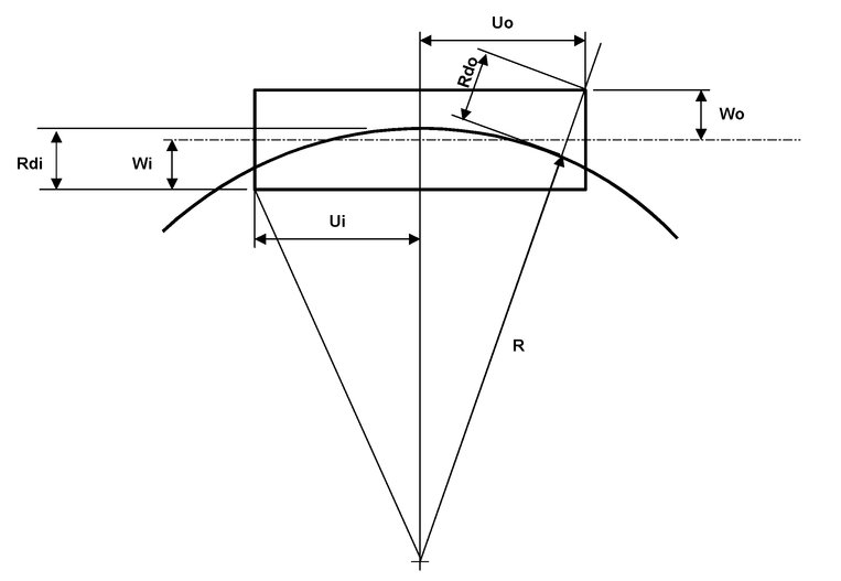
The overthrows at a point on a vehicle body is the difference between the radial distance from the track centreline to the point (Rdo or Rdi), and the lateral distance from the vehicle centreline to the point (Wo or Wi). This is calculated with the vehicle stationary.
Consider a vehicle with bogie centres L, and a bogie axle semi-spacing of ao (The actual axle spacing is 2 × ao)
The inner overthrow of a point Ui from the centre of a vehicle is:

The outer overthrow of a point Uo from the centre of the vehicle is:

Where 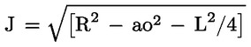
Note that the same calculations can be used for calculating vertical overthrows.
Distance between track centres (section 4.2.4)
Section 4.2.4 of this TSI requires, for a maximum permitted speed V ≤ 230 km/h, that ‘At the design stage, the minimum distance between main track centres on lines ... upgraded for high-speed is ... if < 4,00 m, determined on the basis of the reference kinematic profile (§ 4.2.3)’.
The reference profile to be used is the UK1 (Issue 2) profile set out in Chapter 7 of the High Speed Rolling Stock TSI and section 7.3.6 of this TSI.
This requirement can be met by a distance between track centres of 3 400 mm on straight track and curved track with a radius of 400 m or greater.
Platforms (section 4.2.20)
1. Platform height
For platforms on upgraded lines in Great Britain where trains complying with the High Speed Rolling Stock TSI are intended to stop in normal commercial operation, the height at the edge of the platform shall be 915 mm (within a tolerance of + 0, - 50 mm) measured at right angles to the plane of the rails of the track adjacent to the platform.
2. Platform horizontal distance (platform offset)
For platforms on upgraded lines in Great Britain where trains complying with the High Speed Rolling Stock TSI are intended to stop in normal commercial operation, the platform edge shall be the minimum distance from the adjacent track (within a tolerance of + 15, - 0 mm) consistent with the lower sector structure gauge set out in Appendix 1 to Railway Group Standard GC/RT5212 (Issue 1, February 2003).
For most rolling stock, this requirement is met on curves with radii greater than or equal to 360 m by a platform offset of 730 mm (within a tolerance of + 15, - 0 mm). Appendix 1 to Railway Group Standard GC/RT5212 (Issue 1, February 2003) sets out exceptions where Class 373 (Eurostar) trains or 2,6 m wide containers are required to pass the platform. Appendix 1 to Railway Group Standard GC/RT5212 (Issue 1, February 2003) also sets out requirements where the curve radius is less than 360 m
3. Minimum platform length
For platforms on upgraded lines in Great Britain where trains complying with the High Speed Rolling Stock TSI are intended to stop in normal commercial operation, the usable length of the platform shall be at least 300 m.
The length of platforms on upgraded lines in Great Britain where trains complying with the High Speed Rolling Stock TSI are intended to stop in normal commercial operation shall be indicated in the Infrastructure Register.
T Cases
None
7.3.6.3 Lines of category III
P cases
All specific P cases applicable to Category II lines also apply to Category III lines.
T Cases
None
7.3.7. Particular features on the Hellenic network
7.3.7.1 Lines of category I
P cases
None
T cases
None
7.3.7.2 Lines categories II and III
P cases
Structure gauge
The structure gauge of the line Athinai-Thessaloniki-Idomeni and Thessaloniki-Promahona is GB but in some sections of the lines is limited to GA
The structure gauge on the line Athinai-Kiato is GB.
Minimum length of passenger platforms and stabling tracks
On the line Athinai-Thessaloniki-Idomeni and Thessaloniki-Promahona, the minimum usable length for passenger platforms and stabling tracks is 200 m.
On Promahona station: 189 m.
On the line Athinai-Kiato the minimum usable length for passenger platforms and stabling tracks are as follows:
On the SKA, Megara, Ag.Theodoroi and Kiato Stations: 300 m
On Thriasio station: 150 m
On Magula station: 200 m
Track gauge
The Athinai — Patras line is laid to a gauge of 1 000 mm. A gradual upgrading to the gauge of 1 435 mm is foreseen.
T cases
None
7.3.8. Particular features on Ireland and Northern Ireland networks
P cases
Structure gauge
The minimum structure gauge to be used on the lines in Ireland and Northern Ireland is the IRL1 Irish standard structure gauge.

Notes:
|
1. |
On horizontal curves, due allowance must be made for curvature and cant effects. |
|
2. |
On vertical curves, due allowance must be made for the effects of such curvature. |
|
3. |
The underclearance protrusion limit of 60 mm for structures is subject to all the restrictions set down in standard PW4. The protrusion figure is zero for the Dublin Suburban Area (see standard PW4 for minor exceptions). |
|
4. |
Bridges:
|
||||||||||||||||||||||||||||||||||||||||||||||||
|
5. |
There is an allowance for a 700 mm wide walkway. Where no walkway is provided, the dimension referred to may be reduced to 1 790 mm. |
|
6. |
See standard PW39 for comprehensive schedule of platform widths. |
Track gauge
The railway networks of Ireland and Northern Ireland are made up of lines laid to a gauge of 1 602 mm. By application of Article 7(b) of Council Directive 96/48/EC as amended by Directive 2004/50/EC, projects for new lines in Ireland and Northern Ireland shall keep that gauge.
Minimum radius of curvature
As a track gauge of 1 602 mm will be kept, the provisions of the present TSI concerning the minimum curve radius and the associated elements (track cant and cant deficiency) are not applicable on the railway networks of Ireland and Northern Ireland.
Minimum length of passenger platforms and stabling tracks
On the lines of Ireland and Northern Ireland networks, the minimum usable length for passenger platforms and stabling tracks used by high-speed trains is set at 215 m.
Platform height
On the lines of Ireland and Northern Ireland networks, platforms shall have a design height of 915 mm. Platform heights shall be chosen so as to make optimal use of the step positions on trains built to the IRL1 loading gauge.
Distance between track centres
The minimum distance between track centres on existing lines in Ireland and Northern Ireland shall be increased in advance of upgrading to ensure safe passing clearance between trains.
7.3.9. Particular features on the Italian network
7.3.9.1 Lines of category I, II and III
Distance of the platform from the centre of the track for the platforms with the height of 550 mm
P cases
On the lines of the Italian network, for the platforms with the height of 550 mm, the nominal distance L from the track centre parallel to the running plane is obtained from the formula:
|
on straight track and inside the curves: |
|
|
outside the curves: |
|
where δ is the angle of the cant with the horizontal line.
T cases
None
7.3.10. Particular features on the Netherlands network
7.3.10.1 Lines of category I
P cases
None
T cases
None
7.3.10.2 Lines of category II and III
P cases
Platform height is 840 mm
T cases
None
7.3.11. Particular features on the Portuguese network
7.3.11.1 Lines of category I
P cases
None
T cases
None
7.3.11.2 Lines of category II and III
P cases
Track gauge of 1 668 mm
T cases
None
7.3.12. Particular features on the Swedish network
7.3.12.1 Lines of category I
P cases
Minimum platform length
The minimum platform length is reduced to 225 m.
Stabling tracks: minimum length
The length of stabling tracks may be limited so as to accommodate for a maximum train length of 225 m.
Platforms — distance from centre of track
The nominal distance L from the track centre parallel to the running plane shall be,
L = 1 700 mm + Si, o L (mm), S (mm)
where S is depending on curve radii (R) and installed cant (D) obtained from the formula:
For inner curves:
|
Si = 41 000 /R + D/3* |
(for platform height 580 mm) |
|
|
(for platform height 730 mm D/2)* |
For outer curves:
So = 31 000/R - D/4
R (m), D (mm)
Tolerances for the (positioning) nominal distance L (1 700 mm) of the platform edges are in mm:
|
New construction: |
- 0, + 40 |
|
Maintenance tolerance: |
- 30, + 50 |
|
Safety limit tolerance: |
- 50 |
T cases
None
7.3.12.2 Lines of category II
P cases
Same cases apply than for category I lines.
T cases
Platform height
The nominal platform height is 580 mm or 730 mm
7.3.12.3 Lines of category III
P cases
Same cases apply than for category I lines.
T cases
Platform height
The nominal platform height is 580 mm or 730 mm
7.3.13. Particular features on the Polish network
P cases
Structure gauge
The structure gauge must allow trains built to gauge GB and OSZD 2-SM (see diagram below)

7.4. TSI Revision
In conformity with article 6(3) of Directive 96/48/EC as amended by Directive 2004/50/EC, the Agency shall be responsible for preparing the review and updating of TSIs and making appropriate recommendations to the Committee referred to in Article 21 of this directive in order to take account of developments in technology or social requirements. In addition, the progressive adoption and revision of other TSIs may also impact this TSI. Proposed changes to this TSI shall be subject to rigorous review and updated TSIs will be published on an indicative periodic basis of 3 years. This will also include the possibility of including noise parameters for infrastructure.
The study shall be limited to only those routes that are required to be noise-mapped under the Environmental Noise Directive 2002/49/EC of 22 June 2002. Infrastructure treatments to be referred to shall be restricted to measures at source, e.g. railhead roughness control and the acoustic optimisation of track dynamic characteristics.
7.5. Agreements
7.5.1. Existing agreements
Member States shall notify the Commission, within 6 months after the entry into force of this TSI, of the following agreements under which the subsystems related to the scope of this TSI (construction, renewal, upgrading, placing in service, operation and maintenance of subsystems as defined in Chapter 2 of this TSI) are operated:
|
— |
national, bilateral or multilateral agreements between Member States and Infrastructure Managers or Railway Undertakings, agreed on either a permanent or temporary basis, and required due to the very specific or local nature of the intended transport service; |
|
— |
bilateral or multilateral agreements between Infrastructure Managers, Railway Undertakings or between Member States, which deliver significant levels of local or regional interoperability; |
|
— |
international agreements between one or more Member States and at least one third country, or between Infrastructure Managers or Railway Undertakings of Member States and at least one Infrastructure Manager or Railway Undertaking of a third country, which deliver significant levels of local or regional interoperability. |
Continued operation/maintenance of the subsystems in the scope of this TSI covered by these agreements shall be permitted as far as they do comply with Community legislation.
The compatibility of these agreements with EU legislation including their non-discriminatory character and, in particular, this TSI, will be assessed and the Commission will take the necessary measures such as, for example, the revision of this TSI to include possible specific cases or transitional measures.
7.5.2. Future agreements
Any future agreement or modification of existing agreements shall take into account EU legislation and, in particular, this TSI. Member States shall notify the Commission with such agreements/modifications. The same procedure of § 7.5.1 then applies.
(1) Sections of Annex III of Directive 96/48/EC, as amended by Directive 2004/50/EC.
(2) The rail temperature increase due to energy dissipated in it amounts to 0,035 oC per kN of braking force per rail string; this corresponds (for both rail strings) to rail temperature increases of around 6 oC per train in case of emergency braking.
(2) It must be underlined that actual track quality is not the reference track quality defined to assess rolling stock against pass-by noise limits.
(*) In the case of established products placed on the market before the publication of this version of the TSI, the type is considered to have been approved and therefore type examination (module B) is not necessary. However, the manufacturer shall demonstrate that tests and verification of interoperability constituents have been considered successful for previous applications under comparable conditions and are in conformity with the requirements of this TSI. In this case these assessments shall remain valid in the new application. If it is not possible to demonstrate that the solution is positively proven in the past, procedure E2 applies.
ANNEX A
Interoperability constituents of the infrastructure domain
A.1. Scope
This annex describes the Conformity assessment of the Interoperability Constituents of the infrastructure domain.
A.2. Characteristics to be assessed for ‘established’ interoperability constituents.
The characteristics of the interoperability constituents to be assessed in the different phases of design, development and production are marked by ‘X’ in Table A. Where no assessment by a Notified Body is required, this is marked by ‘n.a.’ in the table.
Table A1
Assessment of interoperability constituents for the EC declaration of conformity
|
Characteristics to be assessed |
Assessment in the following phase |
||||||
|
Design and development phase |
Production phase |
||||||
|
Design review |
Review of manufacturing process |
Type test |
|
Product quality (series) |
|||
|
|
|
|
|
|
||
|
X |
X |
n.a. |
|
X |
||
|
X |
n.a. |
n.a. |
|
n.a. |
||
|
X |
X |
n.a. |
|
X |
||
|
|
|
|
|
|
||
|
n.a. |
n.a. |
X |
|
X |
||
|
n.a. |
n.a. |
X |
|
X |
||
|
n.a. |
n.a. |
X |
|
X |
||
|
n.a. |
n.a. |
X |
|
X |
||
|
|
|
|
|
|
||
|
X |
X |
X |
|
X |
||
|
X |
X |
X |
|
X |
||
|
|
|
|
|
|
||
|
X |
n.a. |
n.a. |
|
n.a. |
||
|
X |
n.a. |
n.a. |
|
n.a. |
||
|
X |
X |
n.a. |
|
X |
||
|
|
|
|
|
|
||
|
X |
n.a. |
n.a. |
|
X |
||
A.3 Characteristics to be assessed for ‘novel’ Interoperability constituents
Novel interoperability constituents are to be assessed at design phase against the requirements of Chapter 4, as marked in table A2. Where no assessment by a Notified Body is required, this is marked by ‘n.a.’ in the table.
For the switches and crossings, the parts of Chapter 4 to be used for assessment are set out in Chapter 5.
At the production phase, the characteristics of novel interoperability constituents set out in the technical specifications given in the technical file are to be assessed according to the module selected.
Table A2
Assessment of a novel interoperability constituent for the EC verification of conformity
|
|
Interoperability constituents |
||||
|
Characteristics to be assessed |
Rail |
Fastening systems |
Sleepers |
||
|
n.a |
n.a |
Design review |
||
|
n.a |
n.a |
n.a |
||
|
n.a |
n.a |
n.a |
||
|
n.a |
n.a |
n.a |
||
|
n.a |
Design review |
n.a |
||
|
n.a |
n.a |
n.a |
||
|
n.a |
n.a |
n.a |
||
|
Design review |
Design review |
Design review |
||
|
Design review — In service |
Design review — In service |
Design review — In service |
||
|
n.a |
n.a |
n.a |
||
|
Design review |
Design review |
Design review |
||
|
n.a |
n.a |
n.a |
||
|
n.a |
n.a |
n.a |
||
|
n.a |
n.a |
n.a |
||
|
n.a |
n.a |
n.a |
||
|
Design review |
Design review |
Design review |
||
|
n.a |
n.a |
n.a |
||
|
n.a |
Type test |
n.a |
||
|
n.a |
n.a |
n.a |
||
|
n.a |
n.a |
n.a |
||
|
|
Type test |
Type test |
||
|
n.a |
n.a |
n.a |
||
|
n.a |
n.a |
n.a |
||
|
n.a |
n.a |
n.a |
||
|
n.a |
n.a |
n.a |
||
|
n.a |
n.a |
n.a |
||
|
n.a |
n.a |
n.a |
||
|
n.a |
n.a |
n.a |
||
|
n.a |
n.a |
n.a |
||
|
n.a |
n.a |
n.a |
||
|
n.a |
n.a |
n.a |
||
|
n.a |
n.a |
n.a |
||
|
n.a |
n.a |
n.a |
||
|
n.a |
n.a |
n.a |
||
|
n.a |
n.a |
n.a |
||
|
n.a |
Design review |
n.a |
||
ANNEX B1
Assessment of the infrastructure subsystem
B1.1. Scope
This annex indicates the assessment of conformity of the infrastructure subsystem.
B1.2. Characteristics and modules
The characteristics of the subsystem to be assessed in the different phases of design, construction and operation are marked by ‘X’ in Table B1. Where no assessment by a Notified Body is required, this is marked by ‘n.a.’ in the table.
This does not prevent the need for other assessments to be performed in the framework of other phases.
Definition of assessment phases:
|
1 |
‘Detailed design and execution design, before construction’: it includes checking of correctness of values/parameters against applicable TSI requirements. |
|
2 |
‘Constructed, before putting into service’: checking on the field that the actual product complies with the relevant design parameters just before putting it into operation |
|
3 |
‘Validation under full operation conditions’: checking the state of the subsystem during operation, |
Table B1
Assessment of the infrastructure subsystem for the EC verification of conformity
|
|
Assessment phases |
||||
|
|
1 |
2 |
3 |
||
|
Characteristics to be assessed |
Detailed design and execution design, before construction |
Constructed, before putting into service |
Validation under full operation conditions |
||
|
X |
n.a. |
n.a. |
||
|
X |
X |
n.a. |
||
|
X |
X |
n.a. |
||
|
X |
n.a. |
n.a. |
||
|
X |
X |
n.a. |
||
|
X |
X |
n.a. |
||
|
X |
n.a. |
n.a. |
||
|
X |
n.a. |
n.a. |
||
|
n.a. |
X |
n.a. |
||
|
n.a. |
n.a. |
n.a. |
||
|
X |
n.a. |
n.a. |
||
|
|
|
|
||
|
n.a. |
n.a. |
n.a. |
||
|
X |
n.a. |
n.a. |
||
|
n.a. |
n.a. |
n.a. |
||
|
X |
n.a. |
n.a. |
||
|
X |
n.a. |
n.a. |
||
|
reserved |
reserved |
n.a. |
||
|
X |
n.a. |
n.a. |
||
|
n.a. |
n.a. |
n.a. |
||
|
n.a. |
n.a. |
n.a. |
||
|
n.a. |
n.a. |
n.a. |
||
|
|
|
|
||
|
X |
n.a. |
n.a. |
||
|
X |
n.a. |
n.a. |
||
|
X |
X |
n.a |
||
|
X |
n.a. |
n.a. |
||
|
X |
n.a. |
n.a. |
||
|
X |
n.a. |
n.a. |
||
|
n.a. |
n.a. |
n.a. |
||
|
X |
n.a. |
n.a. |
||
|
X |
X |
n.a. |
||
|
|
|
|
||
|
X |
n.a. |
n.a. |
||
|
X |
n.a. |
n.a. |
||
|
X |
n.a. |
n.a. |
||
ANNEX B2
Assessment of the maintenance subsystem
B2.1. Scope
This annex indicates the assessment of conformity of that part of the maintenance subsystem dealing with fixed installations relating to train servicing.
B2.2. Characteristics
The characteristics of the subsystem to be assessed in the different phases of design, construction and operation are marked by ‘X’ in Table B2. Where no assessment is required, this is marked by ‘n.a.’ in the table.
Table B2
Assessment of the maintenance subsystem by the Member State
|
|
1 |
2 |
3 |
||
|
Characteristics to be assessed |
Detailed design and execution design, before construction |
Constructed, before putting into service |
Validation under full operation conditions |
||
|
|
|
|
||
|
Connectors for toilet discharge |
X |
n.a. |
n.a. |
||
|
Washing machine height to clean |
X |
n.a. |
X |
||
|
Washing machine speed |
X |
n.a. |
n.a |
||
|
Quality of water |
X |
n.a. |
X |
||
|
Quality of sand |
n.a. |
n.a. |
X |
||
|
Quality of fuel |
n.a. |
n.a. |
X |
ANNEX C
Assessment procedures
Modules for Interoperability Constituents
Module A: Internal Production Control
|
1. |
This module describes the procedure whereby the manufacturer or his authorised representative established within the Community, who carries out the obligations laid down in point 2, ensures and declares that the interoperability constituent concerned satisfies the requirements of the TSI that apply to it. |
|
2. |
The manufacturer shall establish the technical documentation described in point 3. |
|
3. |
The technical documentation shall enable the conformity of the interoperability constituent with the requirements of the TSI to be assessed. It shall, as far as relevant for such assessment, cover the design, manufacture, maintenance and operation of the interoperability constituent. So far as relevant for the assessment, the documentation shall contain:
|
|
4. |
The manufacturer shall take all the measures necessary in order that the manufacturing process ensures compliance of each manufactured interoperability constituent with the technical documentation referenced in point 3 and with the requirements of the TSI that apply to it. |
|
5. |
The manufacturer or his authorised representative established within the Community shall draw up a written declaration of conformity for the interoperability constituent. The content of this declaration has to include at least the information indicated in Annex IV (3) and in Article 13 -3 of Directives 96/48/EC. The EC declaration of conformity and the accompanying documents shall be dated and signed. The declaration shall be written in the same language as the technical documentation and shall contain the following:
|
|
6. |
The manufacturer or his authorised representative shall keep a copy of the EC declaration of conformity with the technical documentation for a period of 10 years after the last interoperability constituent has been manufactured. Where neither the manufacturer nor his authorised representative is established within the Community, the obligation to keep the technical documentation available is the responsibility of the person who places the interoperability constituent in the Community market. |
|
7. |
If additional to the EC declaration of conformity, an EC declaration for suitability for use for the interoperability constituent is required by the TSI, this declaration has to be added after being issued by the manufacturer under the conditions of module V. |
Module A: Internal Design Control with Production Verification
|
1. |
This module describes the procedure whereby the manufacturer or his authorised representative established within the Community, who carries out the obligations laid down in point 2, ensures and declares that the interoperability constituent concerned satisfies the requirements of the TSI that apply to it. |
|
2. |
The manufacturer shall establish the technical documentation described in point 3. |
|
3. |
The technical documentation shall enable the conformity of the interoperability constituent with the requirements of the TSI to be assessed. The technical documentation shall also give evidence that the design of the interoperability constituent, already accepted before the implementation of the present TSI, is in accordance with the TSI and that the interoperability constituent has been used in service in the same area of use. It shall, as far as relevant for such assessment, cover the design, manufacture, maintenance and operation of the interoperability constituent. So far as relevant for the assessment, the documentation shall contain:
|
|
4. |
The manufacturer shall take all the measures necessary in order that the manufacturing process ensures compliance of each manufactured interoperability constituent with the technical documentation referenced in point 3 and with the requirements of the TSI that apply to it. |
|
5. |
The notified body, chosen by the manufacturer, shall carry out the appropriate examinations and tests in order to verify the conformity of the manufactured interoperability constituents with the type described in the technical documentation referenced in point 3 and with the requirement of the TSI. The manufacturer (3) can choose one of the following procedures: |
|
5.1 |
Verification by examination and testing of every product |
|
5.1.1 |
Each product shall be individually examined and appropriate tests shall be carried out in order to verify the product conformity with the type described in the technical documentation and the requirements of the TSI that apply to it. When a test is not set out in the TSI (or in an European Standard quoted in the TSI), the relevant European Specifications or equivalent tests are applicable |
|
5.1.2 |
The notified body shall draw up a written certificate of conformity for the approved products relating to the tests carried out. |
|
5.2 |
Statistical verification |
|
5.2.1 |
The manufacturer shall present his products in the form of homogeneous lots and shall take all measures necessary in order that the manufacturing process ensures the homogeneity of each lot produced. |
|
5.2.2 |
All interoperability constituents shall be available for verification in the form of homogeneous lots. A random sample shall be drawn from each lot. Each interoperability constituents in a sample shall be individually examined and appropriate tests shall be carried out to ensure the product conformity with the type described in the technical documentation and the requirements of the TSI which apply to it and to determine whether the lot is accepted or rejected. When a test is not set out in the TSI (or in an European Standard quoted in the TSI), the relevant European Specifications or equivalent tests are applicable |
|
5.2.3 |
The statistical procedure shall use appropriate elements (statistical method, sampling plan etc), depending on the characteristics to be assessed, as specified in the TSI. |
|
5.2.4 |
In the case of accepted lots, the notified body shall draw up a written certificate of conformity relating to the tests carried out. All interoperability constituents in the lot may be placed on the market except those interoperability constituents from the sample, which were found not to be in conformity. |
|
5.2.5 |
If a lot is rejected, the notified body or the competent authority shall take appropriate measures to prevent placing that lot on the market. In the event of frequent rejection of lots the notified body shall suspend the statistical verification. |
|
6. |
The manufacturer or his authorised representative established within the Community shall draw up the EC declaration of conformity of the interoperability constituent. The content of this declaration shall include at least the information indicated in Annex IV (3) and in Article 13-3 of Directive 96/48/EC. The EC declaration of conformity and the accompanying documents shall be dated and signed. The declaration shall be written in the same language as the technical documentation and shall contain the following:
The certificate to be referred to, is the certificate of conformity as mentioned in point 5. The manufacturer or his authorised representative established within the Community shall ensure that he is able to supply the notified body's certificates of conformity on request |
|
7. |
The manufacturer or his authorised representative shall keep a copy of the EC declaration of conformity with the technical documentation for a period of 10 years after the last interoperability constituent has been manufactured. Where neither the manufacturer nor his authorised representative is established within the Community, the obligation to keep the technical documentation available is the responsibility of the person who places the interoperability constituent in the Community market. |
|
8. |
If additional to the EC declaration of conformity, an EC declaration for suitability for use for the interoperability constituent is required by the TSI, this declaration has to be added after being issued by the manufacturer under the conditions of module V. |
Module B: Type Examination
|
1. |
This module describes that part of the procedure by which a notified body ascertains and attests that a type, representative of the production envisaged, meets the provisions of the TSI that apply to it. |
|
2. |
The application for the EC type-examination shall be lodged by the manufacturer or his authorised representative established within the Community. The application shall include:
The applicant shall place at the disposal of the notified body a specimen, representative of the production envisaged and hereinafter called ‘type’. A type may cover several versions of the Interoperability Constituent provided that the differences between the versions do not affect the provisions of the TSI. The notified body may request further specimens if needed for carrying out the test programme. If no type tests are requested within the type examination procedure, and the type is sufficiently defined by the technical documentation, as described in point 3, the notified body shall agree that no specimens are placed at its disposal. |
|
3. |
The technical documentation shall enable the conformity of the interoperability constituent with the requirements of the TSI to be assessed. It shall, as far as relevant for such assessment, cover the design, manufacture, maintenance and operation of the interoperability constituent. The technical documentation shall contain:
|
|
4. |
The notified body shall: |
|
4.1 |
examine the technical documentation, |
|
4.2 |
verify that any specimen(s) required for tests has (have) been manufactured in conformity with the technical documentation, and carry out or have carried out the type tests in accordance with the provisions of the TSI and/or the relevant European specifications, |
|
4.3 |
where a design review is requested in the TSI, perform an examination of the design methods, the design tools and the design results to evaluate their capability to fulfil the requirements for conformity for the interoperability constituent at the completion of the design process, |
|
4.4 |
where a review of the manufacturing process is requested in the TSI, perform an examination of the manufacturing process devised for manufacturing the interoperability constituent, to evaluate its contribution to product conformity, and/or examine the review carried out by the manufacturer at the completion of the design process, |
|
4.5 |
identify the elements which have been designed in accordance with the relevant provisions of the TSI and the European specifications as well as the elements which have been designed without applying the relevant provisions of those European Specifications; |
|
4.6 |
perform or have performed the appropriate examinations and necessary tests in accordance with points 4.2., 4.3. and 4.4 to establish whether, where the manufacturer has chosen to apply the relevant European specifications, these have actually been applied; |
|
4.7 |
perform or have performed the appropriate examinations and necessary tests in accordance with points 4.2., 4.3. and 4.4. to establish whether, where the relevant European specifications have not been applied, the solutions adopted by the manufacturer meet the requirements of the TSI; |
|
4.8 |
agree with the applicant the location where the examinations and necessary tests will be carried out. |
|
5. |
Where the type meets the provisions of the TSI, the notified body shall issue a type-examination certificate to the applicant. The certificate shall contain the name and address of the manufacturer, conclusions of the examination, conditions for its validity and the necessary data for identification of the approved type. The time period of validity shall be no longer than 5 years. A list of the relevant parts of the technical documentation shall be annexed to the certificate and a copy kept by the notified body. If the manufacturer or his authorised representative established within the Community is denied a type-examination certificate, the notified body shall provide detailed reasons for such denial. Provision shall be made for an appeals procedure. |
|
6. |
The applicant shall inform the notified body that holds the technical documentation concerning the type-examination certificate of all modifications to the approved product which may affect the conformity with the requirements of the TSI or the prescribed conditions for use of the product. In such cases the interoperability constituent shall receive additional approval from the notified body that issued the EC type examination certificate. In this case, the notified body shall perform only those examinations and tests that are relevant and necessary to the changes. The additional approval shall be given either in the form of an addition to the original type-examination certificate, or, by the issue of a new certificate after withdrawal of the old one. |
|
7. |
If no modifications as in point 6 have been made, the validity of an expiring certificate can be extended for another period of validity. The applicant will apply for such a prolongation by a written confirmation that no such modifications have been made, and the notified body issues a prolongation for another period of validity as in point 5, if no contrary information exists. This procedure can be reiterated. |
|
8. |
Each notified body shall communicate to the other notified bodies the relevant information concerning the type-examination certificates and additions issued, withdrawn or refused. |
|
9. |
The other notified bodies shall receive, on request, copies of the type-examination certificates issued and/or their additions. The annexes to the certificates (see § 5) shall be kept at the disposal of the other notified bodies. |
|
10. |
The manufacturer or his authorised representative established within the Community shall keep with the technical documentation copies of type-examination certificates and their additions for a period of 10 years after the last interoperability constituent has been manufactured. Where neither the manufacturer nor his authorised representative is established within the Community, the obligation to keep the technical documentation available is the responsibility of the person who places the interoperability constituent on the Community market. |
Module D: Production Quality Management System
|
1. |
This module describes the procedure whereby the manufacturer or his authorised representative established within the Community who satisfies the obligations of point 2 ensures and declares that the interoperability constituent concerned is in conformity with the type as described in the type-examination certificate and satisfies the requirements of the TSI that apply to it. |
|
2. |
The manufacturer shall operate an approved quality management system for production, final product inspection and testing as specified in point 3 and is subject to monitoring as specified in point 4. |
|
3. |
Quality management system |
|
3.1 |
The manufacturer shall lodge an application for assessment of his quality management system with a notified body of his choice, for the interoperability constituents concerned. The application shall include:
|
|
3.2 |
The quality management system shall ensure compliance of the interoperability constituents with the type as described in the type-examination certificate and with the requirements of the TSI that apply to them. All the elements, requirements and provisions adopted by the manufacturer shall be documented in a systematic and orderly manner in the form of written policies, procedures and instructions. The quality management system documentation shall permit a consistent interpretation of the quality programmes, plan, manuals and records. It shall contain in particular an adequate description of:
|
|
3.3 |
The notified body assesses the quality management system to determine whether it satisfies the requirements of point 3.2. It presumes compliance with these requirements if the manufacturer implements a quality system for production, final product inspection and testing in respect of the Standard EN/ISO 9001-2000, which take into consideration the specificity of the interoperability constituent for which it is implemented. When the manufacturer operates a certified quality management system, the notified body shall take this into account in the assessment. The audit shall be specific for the product category, which is representative for the interoperability constituent. The auditing team shall have at least one member experienced as an assessor in the product technology concerned. The evaluation procedure shall include an inspection visit to the manufacturer's premises. The decision shall be notified to the manufacturer. The notification shall contain the conclusions of the examination and the reasoned assessment decision. |
|
3.4 |
The manufacturer shall undertake to fulfil the obligations arising out of the quality management system as approved and to uphold it so that it remains adequate and efficient. The manufacturer or his authorised representative established within the Community shall keep the notified body that has approved the quality management system informed of any intended updating of the quality management system. The notified body shall evaluate the modifications proposed and decide whether the amended quality management system will still satisfy the requirements of point 3.2 or whether a re-assessment is required. It shall notify its decision to the manufacturer. The notification shall contain the conclusions of the examination and the reasoned assessment decision. |
|
4. |
Surveillance of the quality management system under the responsibility of the notified body. |
|
4.1 |
The purpose of surveillance is to make sure that the manufacturer duly fulfils the obligations arising out of the approved quality management system. |
|
4.2 |
The manufacturer shall allow the notified body entrance for inspection purposes to the locations of manufacture, inspection and testing, and storage and shall provide it with all necessary information, in particular:
|
|
4.3 |
The notified body shall periodically carry out audits to make sure that the manufacturer maintains and applies the quality management system and shall provide an audit report to the manufacturer. The frequency of the audits shall be at least once a year. When the manufacturer operates a certified quality management system, the notified body shall take this into account in the surveillance. |
|
4.4 |
Additionally the notified body may pay unexpected visits to the manufacturer. During such visits the notified body may carry out, or cause to be carried out, tests to verify that the quality management system is functioning correctly, if necessary. The notified body shall provide the manufacturer with a visit report and, if a test has taken place, with a test report. |
|
5. |
Each notified body shall communicate to the other notified bodies the relevant information concerning the quality management system approvals, issued, withdrawn or refused. The other notified bodies may receive on request copies of the quality management system approvals issued. |
|
6. |
The manufacturer shall, for a period of 10 years after the last product has been manufactured, keep at the disposal of the national authorities:
|
|
7. |
The manufacturer or his authorised representative established within the Community shall draw up the EC declaration of conformity of the interoperability constituent. The content of this declaration shall include at least the information indicated in Annex IV (3) and in Article 13-3 of Directive 96/48/EC. The EC declaration of conformity and the accompanying documents shall be dated and signed. The declaration shall be written in the same language as the technical documentation and shall contain the following:
The certificates to be referred to are:
|
|
8. |
The manufacturer or his authorised representative established within the Community shall keep a copy of the EC declaration of conformity for a period of 10 years after the last interoperability constituent has been manufactured. Where neither the manufacturer nor his authorised representative is established within the Community, the obligation to keep the technical documentation available is the responsibility of the person who places the interoperability constituent on the Community market. |
|
9. |
If additional to the EC declaration of conformity an EC declaration of suitability for use for the interoperability constituent is requested in the TSI, this declaration has to be added, after being issued by the manufacturer under the conditions of Module V. |
Module F: Product Verification
|
1. |
This module describes the procedure whereby a manufacturer or his authorised representative established within the Community checks and attests that the interoperability constituent concerned and subject to the provisions of point 3 is in conformity with the type as described in the EC type examination certificate and satisfies the requirements of the TSI that apply to it. |
|
2. |
The manufacturer shall take all measures necessary in order that the manufacturing process ensures conformity of each interoperability constituent with the type as described in the type-examination certificate and with the requirements of the TSI that apply to it. |
|
3. |
The notified body shall carry out the appropriate examinations and tests in order to check the conformity of the interoperability constituent with the type as described in the EC type examination certificate and with the requirements of the TSI. The manufacturer (6) can choose either an examination and testing of every interoperability constituent as specified in point 4 or an examination and testing of interoperability constituents on a statistical basis, as specified in point 5. |
|
4. |
Verification by examination and testing of every interoperability constituent |
|
4.1 |
Each product shall be individually examined and appropriate tests shall be carried out in order to verify the product conformity with the type as described in the type-examination certificate and with the requirements of the TSI that apply to it. When a test is not set out in the TSI, (or in an European Standard quoted in the TSI), the relevant European Specifications (7), or equivalent tests are applicable. |
|
4.2 |
The notified body shall draw up a written certificate of conformity for the approved products relating to the tests carried out. |
|
4.3 |
The manufacturer or his authorised representative shall ensure that he is able to supply the notified body's certificates of conformity on request. |
|
5. |
Statistical verification |
|
5.1 |
The manufacturer shall present his interoperability constituents in the form of homogeneous lots and shall take all measures necessary in order that the manufacturing process ensures the homogeneity of each lot produced. |
|
5.2 |
All interoperability constituents shall be available for verification in the form of homogeneous lots. A random sample shall be drawn from each lot. Each interoperability constituents in a sample shall be individually examined and appropriate tests shall be carried out to ensure the product conformity with the type as described in the type-examination certificate and with the requirements of the TSI which apply to it and to determine whether the lot is accepted or rejected. When a test is not set out in the TSI (or in an European Standard quoted in the TSI), the relevant European Specifications or equivalent tests are applicable. |
|
5.3 |
The statistical procedure shall use appropriate elements (statistical method, sampling plan etc), depending on the characteristics to be assessed, as specified in the TSI. |
|
5.4 |
In the case of accepted lots, the notified body shall draw up a written certificate of conformity relating to the tests carried out. All interoperability constituents in the lot may be placed on the market except those interoperability constituents from the sample, which were found not to be in conformity. If a lot is rejected, the notified body or the competent authority shall take appropriate measures to prevent placing of that lot on the market. In the event of frequent rejection of lots the notified body shall suspend the statistical verification. |
|
5.5 |
The manufacturer or his authorised representative established within the Community shall ensure that he is able to supply the notified body's certificates of conformity on request. |
|
6. |
The manufacturer or his authorised representative established within the Community shall draw up the EC declaration of conformity of the interoperability constituent. The content of this declaration shall include at least the information indicated in Annex IV (3) and in Article 13-3 of Directive 96/48/EC. The EC declaration of conformity and the accompanying documents shall be dated and signed. The declaration shall be written in the same language as the technical documentation and shall contain the following:
The certificates to be referred to are:
|
|
7. |
The manufacturer or his authorised representative established within the Community shall keep a copy of the EC declaration of conformity for a period of 10 years after the last interoperability constituent has been manufactured. Where neither the manufacturer nor his authorised representative is established within the Community, the obligation to keep the technical documentation available is the responsibility of the person who places the interoperability constituent on the Community market. |
|
8. |
If additional to the EC declaration of conformity an EC declaration of suitability for use for the interoperability constituent is requested in the TSI, this declaration has to be added, after being issued by the manufacturer under the conditions of Module V. |
Module H 1: Full Quality Management System
|
1. |
This module describes the procedure whereby the manufacturer or his authorised representative established within the Community who satisfies the obligations of point 2, ensures and declares that the interoperability constituent concerned satisfies the requirements of the TSI that apply to it. |
|
2. |
The manufacturer shall operate an approved quality management system for design, production and final product inspection and testing as specified in point 3 and shall be subject to surveillance as specified in point 4. |
|
3. |
Quality management system |
|
3.1. |
The manufacturer shall lodge an application for assessment of his quality management system with a notified body of his choice, for the interoperability constituents concerned. The application shall include:
|
|
3.2. |
The quality management system shall ensure compliance of the interoperability constituent with the requirements of the TSI that apply to it. All the elements, requirements and provisions adopted by the manufacturer shall be documented in a systematic and orderly manner in the form of written policies, procedures and instructions. This quality management system documentation shall ensure a common understanding of the quality policies and procedures such as quality programmes, plans, manuals and records. It shall contain in particular an adequate description of:
The quality policies and procedures shall cover in particular the assessment phases as design review, review of manufacturing process and type tests, as they are specified in the TSI, for the different characteristics and performances of the interoperability constituent. |
|
3.3. |
The notified body shall assess the quality management system to determine whether it satisfies the requirements of point 3.2. It presumes compliance with these requirements if the manufacturer implements a quality system for design, production, final product inspection and testing in respect of the Standard EN/ISO 9001-2000, which take into consideration the specificity of the interoperability constituent for which it is implemented. When the manufacturer operates a certified quality management system, the notified body shall take this into account in the assessment. The audit shall be specific for the product category, which is representative for the interoperability constituent. The auditing team shall have at least one member experienced as an assessor in the product technology concerned. The evaluation procedure shall include an assessment visit to the manufacturer's premises. The decision shall be notified to the manufacturer. The notification shall contain the conclusions of the examination and the reasoned assessment decision. |
|
3.4. |
The manufacturer shall undertake to fulfil the obligations arising out of the quality management system as approved and to uphold it so that it remains adequate and efficient. The manufacturer or his authorised representative established within the Community shall keep the notified body that has approved the quality management system informed of any intended updating of the quality management system. The notified body shall evaluate the modifications proposed and decide whether the amended quality management system will still satisfy the requirements of point 3.2 or whether a re-assessment is required. It shall notify its decision to the manufacturer. The notification shall contain the conclusions of the evaluation and the reasoned assessment decision. |
|
4. |
Surveillance of the quality management system under the responsibility of the notified body |
|
4.1. |
The purpose of surveillance is to make sure that the manufacturer duly fulfils the obligations arising out of the approved quality management system. |
|
4.2. |
The manufacturer shall allow the notified body entrance for inspection purposes to the locations of design, manufacture, inspection and testing, and storage, and shall provide it with all necessary information, including particular:
|
|
4.3. |
The notified body shall periodically carry out audits to make sure that the manufacturer maintains and applies the quality management system and shall provide an audit report to the manufacturer. When the manufacturer operates a certified quality management system, the notified body shall take this into account in the surveillance. The frequency of the audits shall be at least once a year. |
|
4.4. |
Additionally the notified body may pay unexpected visits to the manufacturer. At the time of such visits, the notified body may carry out tests or have them carried out in order to check the proper functioning of the quality management system where necessary. It shall provide the manufacturer with a visit report and, if a test has been carried out, with a test report. |
|
5. |
The manufacturer shall, for a period of 10 years after the last product has been manufactured, keep at the disposal of the national authorities:
|
|
6. |
Each notified body shall communicate to the other notified bodies the relevant information concerning the quality management system approvals issued, withdrawn or refused. The other notified bodies may receive on request copies of the quality management system approvals and additional approvals issued. |
|
7. |
The manufacturer or its authorised representative established within the Community shall draw up the EC Declaration of conformity of the interoperability constituent. The content of this declaration shall include at least the information indicated in Annex IV (3) and in Article 13-3 of Directive 96/48/EC. The EC declaration of conformity and the accompanying documents shall be dated and signed. The declaration shall be written in the same language as the technical documentation and shall contain the following:
The certificate to be referred to is:
|
|
8. |
The manufacturer or his authorised representative established within the Community shall keep a copy of the EC declaration of conformity for a period of 10 years after the last interoperability constituent has been manufactured. Where neither the manufacturer nor his authorised representative is established within the Community, the obligation to keep the technical documentation available is the responsibility of the person who places the interoperability constituent on the Community market. |
|
9. |
If additional to the EC declaration of conformity an EC declaration of suitability for use for the interoperability constituent is requested in the TSI, this declaration has to be added, after being issued by the manufacturer under the conditions of Module V. |
Module H2: Full Quality Management System With Design Examination
|
1. |
This module describes the procedure whereby a notified body carries out an examination of the design of an interoperability constituent and the manufacturer or his authorised representative established within the Community who satisfies the obligations of point 2 ensures and declares that the interoperability constituent concerned satisfies the requirements of the TSI that apply to it. |
|
2. |
The manufacturer shall operate an approved quality management system for design, production and final product inspection and testing as specified in point 3 and shall be subject to surveillance as specified in point 4. |
|
3. |
Quality management system. |
|
3.1. |
The manufacturer shall lodge an application for assessment of his quality management system with a notified body of his choice, for the interoperability constituents concerned. The application shall include:
|
|
3.2. |
The quality management system shall ensure compliance of the interoperability constituent with the requirements of the TSI that apply to it. All the elements, requirements and provisions adopted by the manufacturer shall be documented in a systematic and orderly manner in the form of written policies, procedures and instructions. This quality management system documentation shall ensure a common understanding of the quality policies and procedures such as quality programmes, plans, manuals and records. It shall contain in particular an adequate description of:
The quality policies and procedures shall cover in particular the assessment phases, such as design review, review of manufacturing processes and type tests, as they are specified in the TSI, for different characteristics and performances of the interoperability constituent. |
|
3.3. |
The notified body shall assess the quality management system to determine whether it satisfies the requirements of point 3.2. It presumes compliance with these requirements if the manufacturer implements a quality system for design, production, final product inspection and testing in respect of the Standard EN/ISO 9001-2000, which takes into consideration the specificity of the interoperability constituent for which it is implemented. When the manufacturer operates a certified quality management system, the notified body shall take this into account in the assessment. The audit shall be specific for the product category, which is representative for the interoperability constituent. The auditing team shall have at least one member experienced as an assessor in the product technology concerned. The evaluation procedure shall include an assessment visit to the manufacturer's premises. The decision shall be notified to the manufacturer. The notification shall contain the conclusions of the audit and the reasoned assessment decision. |
|
3.4. |
The manufacturer shall undertake to fulfil the obligations arising out of the quality management system as approved and to uphold it so that it remains adequate and efficient. The manufacturer or his authorised representative established within the Community shall keep the notified body that has approved the quality management system informed of any intended updating of the quality management system. The notified body shall evaluate the modifications proposed and decide whether the amended quality management system will still satisfy the requirements of point 3.2 or whether a re-assessment is required. It shall notify its decision to the manufacturer. The notification shall contain the conclusions of the evaluation and the reasoned assessment decision. |
|
4. |
Surveillance of the quality management system under the responsibility of the notified body |
|
4.1. |
The purpose of surveillance is to make sure that the manufacturer duly fulfils the obligations arising out of the approved quality management system. |
|
4.2. |
The manufacturer shall allow the notified body entrance for inspection purposes to the locations of design, manufacture, inspection and testing, and storage, and shall provide it with all necessary information, including:
|
|
4.3. |
The notified body shall periodically carry out audits to make sure that the manufacturer maintains and applies the quality management system and shall provide an audit report to the manufacturer. When the manufacturer operates a certified quality management system, the notified body shall take this into account in the surveillance. The frequency of the audits shall be at least once a year. |
|
4.4. |
Additionally the notified body may pay unexpected visits to the manufacturer. At the time of such visits, the notified body may carry out tests or have them carried out in order to check the proper functioning of the quality management system where necessary. It shall provide the manufacturer with a visit report and, if a test has been carried out, with a test report. |
|
5. |
The manufacturer shall, for a period of 10 years after the last product has been manufactured, keep at the disposal of the national authorities:
|
|
6. |
Design examination |
|
6.1. |
The manufacturer shall lodge an application for examination of the design of the interoperability constituent with a notified body of his choice |
|
6.2. |
The application shall enable the design, manufacture, maintenance and operation of the interoperability constituent to be understood, and shall enable conformity with the requirements of the TSI to be assessed. It shall include:
|
|
6.3 |
The applicant shall present the results of tests (10), including type tests when required, carried out by its appropriate laboratory or on their behalf. |
|
6.4. |
The notified body shall examine the application and assess the results of the tests. Where the design meets the provisions of the TSI that apply to it, the notified body shall issue an EC design examination certificate to the applicant. The certificate shall contain the conclusions of the examination, conditions for its validity, the necessary data for identification of the approved design and, if relevant, a description of the product's functioning. The time period of validity shall be no longer than 5 years. |
|
6.5. |
The applicant shall keep the notified body that has issued the EC design examination certificate informed of all modifications to the approved design, which may affect the conformity with the requirements of the TSI or the prescribed conditions for use of the interoperability constituent. In such cases the interoperability constituent shall receive additional approval from the notified body that issued the EC design examination certificate. In this case, the notified body shall perform only those examinations and tests that are relevant and necessary to the changes. The additional approval shall be given in the form of an addition to the original EC design examination certificate. |
|
6.6. |
If no modifications as in point 6.4. have been made, the validity of an expiring certificate can be extended for another period of validity. The applicant will apply for such a prolongation by a written confirmation that no such modifications have been made, and the notified body issues a prolongation for another period of validity as in point 6.3. if no contrary information exists. This procedure can be reiterated. |
|
7. |
Each notified body shall communicate to the other notified bodies the relevant information concerning the quality management system approvals and the EC design examination certificates, which it has issued, withdrawn or refused. The other notified bodies may receive on request copies of:
|
|
8. |
The manufacturer or his authorised representative established within the Community shall draw up the EC declaration of conformity of the interoperability constituent. The content of this declaration shall include at least the information indicated in Annex IV (3) and in Article 13-3 of Directive 96/48/EC. The EC declaration of conformity and its accompanying documents shall be dated and signed. The declaration shall be written in the same language as the technical documentation and shall contain the following:
The certificates to be referred to are:
|
|
9. |
The manufacturer or his authorised representative established within the Community shall keep a copy of the EC declaration of conformity for a period of 10 years after the last interoperability constituent has been manufactured. Where neither the manufacturer nor his authorised representative is established within the Community, the obligation to keep the technical documentation available is the responsibility of the person who places the interoperability constituent on the Community market. |
|
10. |
If additional to the EC declaration of conformity an EC declaration of suitability for use for the interoperability constituent is requested in the TSI, this declaration has to be added, after being issued by the manufacturer under the conditions of Module V. |
Module V: Type-Validation By In Service Experience (Suitability For Use)
|
1. |
This module describes that part of the procedure by which a notified body ascertains and attests that a specimen, representative of the production envisaged, meets the provisions of the TSI that apply to it for suitability for use, by type validation as demonstrated through in service experience (11). |
|
2. |
The manufacturer, or his authorised representative established within the Community, shall lodge the application for the type-validation by in service experience with a notified body of his choice. The application shall include:
The applicant shall place at the disposal of the company(ies), undertaking the operation of the interoperability constituent in service a specimen or a sufficient number of specimens, representative of the production envisaged and hereinafter called ‘type’. A type may cover several versions of the interoperability constituent provided that the differences between the versions are all covered by EC declarations of conformity and certificates as mentioned above. The notified body may request further specimens if needed for carrying out the validation by in service experience to be put in service. |
|
3. |
The technical documentation shall enable the assessment of the product with the requirements of the TSI. The documentation shall cover the operation of the interoperability constituent, and, as far as relevant for such assessment, cover also the design, manufacture and maintenance. The technical documentation shall contain
and, as far as is relevant for assessment,
If the TSI requires further information for the technical documentation, this shall be included. A list of the European specifications referenced to in the technical documentation, applied in full or in part, shall be attached. |
|
4. |
The programme for the validation by in service experience shall include:
|
|
5. |
The notified body shall: |
|
5.1. |
Examine the technical documentation and the programme for validation by in service experience, |
|
5.2. |
Verify that the type is representative and has been manufactured in conformity with the technical documentation, |
|
5.3. |
Verify that the programme for validation by in service experience is well adapted to assess the required performance and in service behaviour of the interoperability constituent, |
|
5.4. |
Agree with the applicant the programme and the location where the inspections and necessary tests will be carried out and the body performing the tests (notified body or other competent laboratory), |
|
5.5. |
Monitor and inspect the progress of in service running, operation and maintenance of the interoperability constituent, |
|
5.6. |
Evaluate the report, to be issued by the company (ies) (infrastructure managers and/or railway enterprises) operating the interoperability constituent, and all other documentation and information, gained during the procedure (test reports, maintenance experience etc), |
|
5.7. |
Assess, if the in service behaviour meets the requirements of the TSI. |
|
6. |
Where the type meets the provisions of the TSI, the notified body shall issue a suitability for use certificate to the applicant. The certificate shall contain the name and address of the manufacturer, conclusions of the validation, conditions for its validity and the necessary data for identification of the approved type. The time period of validity shall be no longer than 5 years. A list of the relevant parts of the technical documentation shall be annexed to the certificate and a copy kept by the notified body. If the applicant is denied a suitability for use certificate, the notified body shall provide detailed reasons for such denial. Provision shall be made for an appeals procedure. |
|
7. |
The applicant shall inform the notified body that holds the technical documentation concerning the suitability for use certificate of all modifications to the approved product which shall receive additional approval where such changes may affect the suitability for use or the prescribed conditions for use of the product. In this case, the notified body shall perform only those examinations and tests, that are relevant and necessary to the changes. The additional approval shall be given in the form of an addition to the original suitability for use certificate, or by issue of a new certificate issued after withdrawal of the old certificate. |
|
8. |
If no modifications as in point 7 have been made, the validity of an expiring certificate can be extended for another period of validity. The applicant will apply for such a prolongation by a written confirmation that no such modifications have been made, and the notified body issues a prolongation for another period of validity as in point 6, if no contrary information exists. This procedure can be reiterated. |
|
9. |
Each notified body shall communicate to the other notified bodies the relevant information concerning the suitability for use certificates issued, withdrawn or refused. |
|
10. |
The other notified bodies shall be provided on request with copies of the suitability for use certificates issued and/or their additions. The annexes to the certificates shall be kept at the disposal of the other notified bodies. |
|
11. |
The manufacturer or his authorised representative established within the Community shall draw up the EC declaration of suitability for use of the interoperability constituent. The content of this declaration shall include at least the information, indicated in Annex IV (3) and in Article 13-3 of Directive 96/48/EC. The EC declaration of suitability for use and the accompanying documents shall be dated and signed. The declaration shall be written in the same language as the technical documentation and shall contain the following:
|
|
12. |
The manufacturer or his authorised representative established within the Community shall keep a copy of the EC declaration of suitability for use for a period of 10 years after the last interoperability constituent has been manufactured. Where neither the manufacturer nor his authorised representative is established within the Community, the obligation to keep the technical documentation available is the responsibility of the person who places the interoperability constituent on the Community market. |
Modules for the EC Verification of Subsystems
Module SH2: Full Quality Management System with Design Examination
|
1. |
This module describes the EC verification procedure whereby a notified body checks and certifies, at the request of an contracting entity or its authorised representative established within the Community, that the infrastructure subsystem
and may be placed in service |
|
2. |
The notified body shall carry out the procedure, including a design examination of the subsystem, under the condition, that the contracting entity (13) and the main contractor involved are satisfying the obligations of point 3. The ‘main contractor’ refers to companies, whose activities contribute to fulfil the essential requirements of the TSI. It concerns the company:
It does not refer to manufacturer sub contractors supplying components and interoperability constituents. |
|
3. |
For the subsystem that is subject of the EC verification procedure, the contracting entity or the main contractor, when employed, shall operate an approved quality management system for design, manufacture and final product inspection and testing as specified in point 5 and which shall be subject to surveillance as specified in point 6 The main contractor responsible for the whole subsystem project (including in particular responsibility for subsystem integration), shall operate in any case an approved quality management system for design, manufacture and final product inspection and testing, which shall be subject to surveillance as specified in point 6. In the case that the contracting entity itself is responsible for the whole subsystem project (including in particular responsibility for subsystem integration) or that the contracting entity is directly involved in the design and/or production (including assembly and installation), it shall operate an approved quality management system for those activities, which shall be subject to surveillance as specified in point 6. Applicants which are only involved in assembly and installation, are permitted to operate only an approved quality management system for manufacture and final product inspection and testing |
|
4. |
EC verification procedure |
|
4.1 |
The contracting entity shall lodge an application for EC verification of the subsystem (through full quality management system with design examination), including co ordination of surveillance of the quality management systems as in points 5.4. and 6.6., with a notified body of its choice. The contracting entity shall inform the manufacturers involved of his choice and of the application. |
|
4.2 |
The application shall enable the design, manufacture, assembly, installation, maintenance and operation of the subsystem to be understood, and shall enable conformity with the requirements of the TSI to be assessed. The application shall include:
|
|
4.3 |
The contracting entity shall present the results of examinations, checking and tests (15) including type tests when required, carried out by its appropriate laboratory or on their behalf. |
|
4.4 |
The notified body shall examine the application concerning the design examination and assess the results of the tests. Where the design meets the provisions of the Directive and of the TSI that apply to it shall issue a design examination certificate to the applicant. The certificate shall contain the conclusions of the design examination, conditions for its validity, the necessary data for identification of the design examined and, if relevant, a description of the subsystem's functioning. If the contracting entity is denied a design examination certificate, the notified body shall provide detailed reasons for such denial. Provision shall be made for an appeals procedure. |
|
4.5 |
During the production phase, the applicant shall inform the notified body that holds the technical documentation concerning the design examination certificate of all modifications which may affect the conformity with the requirements of the TSI or the prescribed conditions for use of the subsystem. The subsystem shall receive additional approval in such cases. In this case, the notified body shall perform only those examinations and tests; those are relevant and necessary to the changes. This additional approval may be given either in the form of an addition to the original design examination certificate, or by issue of a new certificate after withdrawal of the old certificate. |
|
5. |
Quality management system |
|
5.1 |
The contracting entity, if involved, and the main contractor, when employed, shall lodge an application for assessment of their quality management systems with a notified body of their choice. The application shall include:
For those only involved in a part of the subsystem project, the information to be provided is only that for the relevant part. |
|
5.2 |
For the contracting entity or the main contractor responsible for the whole subsystem project, the quality management system shall ensure overall compliance of the subsystem with the requirements of the TSI. The quality management system(s), for other contractors, has (have) to ensure compliance of their relevant contribution to the subsystem, with the requirements of the TSI. All the elements, requirements and provisions adopted by the applicants shall be documented in a systematic and orderly manner in the form of written policies, procedures and instructions. This quality management system documentation shall ensure a common understanding of the quality policies and procedures such as quality programmes, plans, manuals and records. The system shall contain in particular an adequate description of the following items:
The examinations, tests and checking shall cover all of the following stages:
|
|
5.3 |
The notified body chosen by the contracting entity shall examine, if all stages of the subsystem as mentioned in point 5.2 are sufficiently and properly covered by the approval and surveillance of the quality management system(s) of the applicant(s) (16). If the compliance of the subsystem with the requirements of the TSI is based on more than one quality management system, the notified body shall examine in particular,
|
|
5.4 |
The notified body referenced in point 5.1. shall assess the quality management system to determine whether it satisfies the requirements of point 5.2. It presumes compliance with these requirements if the applicant implements a quality system for design, production, final product inspection and testing in respect of the Standard EN/ISO 9001-2000, which takes into consideration the specificity of the subsystem for which it is implemented. When an applicant operates a certified quality management system, the notified body shall take this into account in the assessment. The audit shall be specific for the subsystem concerned, taking into consideration the specific contribution of the applicant to the subsystem. The auditing team shall have at least one member experienced as an assessor in the subsystem technology concerned. The evaluation procedure shall include an assessment visit to the applicant's premises. The decision shall be notified to the applicant. The notification shall contain the conclusions of the examination and the reasoned assessment decision. |
|
5.5 |
The contracting entity, if involved, and the main contractor shall undertake to fulfill the obligations arising out of the quality management system as approved and to uphold it so that it remains adequate and efficient. They shall keep the notified body that has approved their quality management system informed of any significant change that will affect the fulfilment of the requirements by the subsystem. The notified body shall evaluate any modifications proposed and decide whether the amended quality management system will still satisfy the requirements of point 5.2 or whether a re-assessment is required. It shall notify its decision to the applicant. The notification shall contain the conclusions of the examination and the reasoned assessment decision. |
|
6. |
Surveillance of the quality management system(s) under the responsibility of the notified body |
|
6.1 |
The purpose of surveillance is to make sure that the contracting entity, if involved, and the main contractor duly fulfil the obligations arising out of the approved quality management system(s). |
|
6.2 |
The contracting entity, if involved, and the main contractor shall send the notified body referenced in point 5.1. (or have sent) all the documents needed for that purpose and in particular the implementation plans and technical records concerning the subsystem (as far as relevant for the specific contribution of the applicant to the subsystem), including:
|
|
6.3 |
The notified body shall periodically carry out audits to make sure that the contracting entity, if involved and the main contractor maintain and apply the quality management system and shall provide an audit report to them. When they operate a certified quality management system, the notified body shall take this into account in the surveillance. The frequency of the audits shall be at least once a year, with at least one audit during the time period of performing the relevant activities (design, manufacture, assembly or installation) for the subsystem being the subject of the EC verification procedure mentioned in point 4. |
|
6.4. |
Additionally the notified body may pay unexpected visits to the sites mentioned in point 5.2 of the applicant(s). At the time of such visits, the notified body may conduct complete or partial audits and may carry out or cause to be carried out tests in order to check the proper functioning of the quality management system where necessary. It shall provide the applicant(s) with an inspection report and audit and/or test reports as appropriate. |
|
6.5 |
The notified body chosen by the contracting entity and responsible for the EC verification, if not carrying out the surveillance of all the quality management system(s) concerned as under point 5, shall co ordinate the surveillance activities of any other notified bodies responsible for that task, in order:
This co ordination includes the right of the notified body
|
|
7. |
The notified body as referenced under point 5.1. shall have entrance for inspection purposes, audit and surveillance to the locations of design, building sites, production workshops, locations of assembly and installation, storage areas and where appropriate, prefabrication or testing facilities and, more general, to all premises which it considers necessary for its task, in accordance with the applicant's specific contribution to the subsystem project. |
|
8. |
The contracting entity, if involved, and the main contractor shall, for a period of 10 years after the last subsystem has been manufactured, keep at the disposal of the national authorities:
|
|
9. |
Where the subsystem meets the requirements of the TSI, the notified body shall then, based on the design examination and the approval and surveillance of the quality management system (s), draw up the certificate of conformity intended for the contracting entity, who shall in turn draw up the EC declaration of verification intended for the supervisory authority in the Member State within which the subsystem is located and/or operates. The EC declaration of verification and the accompanying documents shall be dated and signed. The declaration shall be written in the same language of the technical file and shall contain at least the information included in Annex V of the Directive. |
|
10. |
The notified body chosen by the contracting entity shall be responsible for compiling the technical file that has to accompany the EC declaration of verification. The technical file shall include at least the information indicated in Art. 18 (3) of The Directive, and in particular as follows:
|
|
11. |
Each notified body shall communicate to the other notified bodies the relevant information concerning the quality management system approvals and the EC design examination certificates, which it has issued, withdrawn or refused. The other notified bodies may receive on request copies of:
|
|
12. |
The records accompanying the certificate of conformity shall be lodged with the contracting entity The contracting entity shall keep a copy of the technical file throughout the service life of the subsystem and for a further period of three years; it shall be sent to any other Member State which so requests. |
Module SG: Unit Verification
|
1. |
This module describes the EC verification procedure whereby a notified body checks and certifies, at the request of an contracting entity or its authorised representative established within the Community, that the infrastructure subsystem
and may be placed in service. |
|
2. |
The contracting entity (18) shall lodge an application for EC verification (through unit verification) of the subsystem with a notified body of his choice. The application shall include:
|
|
3. |
The technical documentation shall enable the design, manufacture, installation and operation of the subsystem to be understood, and shall enable conformity assessment with the requirements of the TSI. The technical documentation shall include:
If the TSI requires further information for the technical documentation, this shall be included. |
|
4. |
The notified body shall examine the application and the technical documentation, and identify the elements which have been designed in accordance with the relevant provisions of the TSI and the European specifications, as well as the elements which have been designed without applying the relevant provisions of those European specifications. The notified body shall examine the subsystem and verify that the appropriate and necessary tests to establish whether, where the relevant European specifications have been chosen, these have actually been applied or whether the solutions adopted meet the requirements of the TSI when the appropriate European specifications have not been applied. The examinations, tests and checks shall extend to the following stages as provided for in the TSI:
The notified body may take into account evidence of examinations, checking or tests that have been successfully performed, under comparable conditions by other bodies or by (or on the behalf of) the applicant, when this is specified by the relevant TSI. The notified body will then decide as to whether it shall use the results of these checks or tests. The evidences gathered by the notified body shall be suitable and sufficient to show the conformity with the requirement of the TSI and that all required and appropriate checks and tests have been carried out. Any evidence to be used that originates from other parties shall be considered prior to any tests or checks being carried out, since the notified body may wish to undertake any assessment, witnessing or review of the tests or checks at the time they are performed. The extent of such other evidence shall be justified by documented analysis using, among others, the factors listed below. This justification shall be included in the technical file. In all case the notified body keeps the final responsibility of them. |
|
5. |
The notified body shall agree with the contracting entity the locations where the tests will be carried out and shall agree that final subsystem tests and, whenever required in the TSI, tests in full operating conditions, are carried out by the contracting entity under direct supervision and attendance of the notified body. |
|
6. |
The notified body shall have entrance for testing and verification purposes to the locations of design, building sites, production workshops, locations of assembly and installations, and where appropriate, prefabrication and testing facilities in order to carry out its tasks as provided for in the TSI. |
|
7. |
Where the subsystem meets the requirements of the TSI, the notified body shall then, based on the tests, verifications and checks carried out as required in the TSI and/or in the relevant European specifications, draw up the certificate of conformity intended for the contracting entity, who shall in turn draw up the EC declaration of verification intended for the supervisory authority in the Member State where the subsystem is located and/or operates. The EC declaration of verification and the accompanying documents shall be dated and signed. The declaration shall be written in the same language as the technical file and shall contain at least the information included in Annex V of the Directive. |
|
8. |
The notified body shall be responsible for compiling the technical file that has to accompany the EC declaration of verification. The technical file has to include at least the information indicated in Art.18 (3) of the Directive, and in particular as follows:
|
|
9. |
The records accompanying the certificate of conformity shall be lodged with the contracting entity The contracting entity shall keep a copy of the technical file throughout the service life of the subsystem and for a further period of three years; it shall be sent to any other Member State which so requests. |
(1) The definition of an European specification is indicated in the directives 96/48/EC and 01/16/EC. The guide for application of HS TSIs explains the way to use the European Specifications.
(2) The definition of an European specification is indicated in the directives 96/48/EC and 01/16/EC. The guide for application of HS TSIs explains the way to use the European Specifications.
(3) When necessary, the manufacturer's discretion may be limited for specific constituents. In this case, the relevant verification process required for the interoperability constituent is specified in the TSI (or in its annexes).
(4) The definition of an European specification is indicated in the directives 96/48/EC and 01/16/EC. The guide for application of HS TSIs explains the way to use the European Specifications.
(5) The definition of an European specification is indicated in the directives 96/48/EC and 01/16/EC. The guide for application of HS TSIs explains the way to use the European Specifications.
(6) The manufacturer's discretion may be limited in specific TSIs.
(7) The definition of an European specification is indicated in the directives 96/48/EEC and 01/16/EC. The guide for application of HS TSIs explains the way to use the European Specifications.
(8) The definition of an European specification is indicated in the directives 96/48/EC and 01/16/EC. The guide for application of HS TSIs explains the way to use the European Specifications.
(9) The definition of an European specification is indicated in the directives 96/48/EC and 01/16/EC. The guide for application of HS TSIs explains the way to use the European Specifications.
(10) The presentation of the results of the tests can be at the same time as the application or later.
(11) During the time of in service experience, the IC is not placed on the market.
(12) The essential requirements are reflected in the technical parameters, interfaces and performance requirements, which are set out in Chapter 4 of the TSI.
(13) In the module, ‘the contracting entity’ means ‘the subsystem contracting entity, as defined in the directive or his authorised representative established within the Community’.
(14) The definition of an European specification is indicated in the directives 96/48/EC and 01/16/EC. The guide for application of HS TSIs explains the way to use the European Specifications.
(15) The presentation of the results of the tests can be at the same time as the application or later.
(16) In particular, for the rolling stock TSI, the notified body will participate in the final in service testing of rolling stock or train set. This will be indicated in the relevant chapter of the TSI.
(17) The essential requirements are reflected in the technical parameters, interfaces and performance requirements, which are set out in Chapter 4 of the TSI.
(18) In the module, ‘the contracting entity’ means ‘the subsystem contracting entity, as defined in the directive or his authorised representative established within the Community’.
(19) The definition of an European specification is indicated in the directives 96/48/EC and 01/16/EC. The guide for application of HS TSIs explains the way to use the European Specifications.
ANNEX D
Items to be included in the Infrastructure Register concerning the infrastructure domain
|
INFRASTRUCTURE DOMAIN — General Information |
|
|
Route, boundaries and section of line concerned (description) |
|
|
Category of the section of line (I, II, III) |
|
|
Speed of the section of line (km/h) |
|
|
Date of putting into service as an interoperable line |
|
Legend:
Note (1): compliant with chapters 4 and 5 of High-Speed Infrastructure TSI:
|
Y |
= |
compliant without details; |
|
C |
= |
compliant with details on the chosen values |
Note (2): not compliant with chapters 4 and 5 of High-Speed Infrastructure TSI:
|
N |
= |
not compliant without details; |
|
P |
= |
not compliant with details on the specific case (Chapter 7 TSI); |
P and C only apply to the items indicated in the table
Note (3): in case of application of Article 7 of the Directive 96/48/EC as amended by Directive 2004/50/EC, the chosen values shall be indicated for each item of this table
|
INFRASTRUCTURE domain items |
Ref. § |
(1) |
(2) |
|
Nominal track gauge |
4.2.2 |
Y |
P |
|
Structure gauge |
4.2.3 |
C |
P |
|
Minimum distance between track centres |
4.2.4 |
Y |
P |
|
Maximum gradient |
4.2.5 |
Y |
P |
|
Minimum radius of curvature |
4.2.6 |
Y |
N |
|
Track cant |
4.2.7 |
Y |
N |
|
Cant deficiency |
4.2.8 |
C |
N |
|
Equivalent conicity |
4.2.9 |
Y |
N |
|
Track geometrical quality |
4.2.10 |
n.a. |
n.a. |
|
Rail inclination |
4.2.11 |
Y |
N |
|
Switches and crossings |
4.2.12 |
Y |
P |
|
Track resistance |
4.2.13 |
C |
N |
|
Traffic loads on structures |
4.2.14 |
Y |
N |
|
Maximum pressure variation in tunnels |
4.2.16 |
C |
N |
|
Crosswinds |
4.2.17 |
C |
n.a. |
|
Electrical characteristics |
4.2.18 |
n.a. |
n.a. |
|
Noise and vibrations |
4.2.19 |
n.a. |
n.a. |
|
Platforms |
4.2.20 |
C |
P |
|
Access/Intrusion |
4.2.22 |
Y |
N |
|
Existence of conditions for the detrainment of passengers and onboard staff outside of the platforms |
4.2.23 |
C |
P |
|
Existence and location of stabling tracks complying with the High-Speed Infrastructure TSI |
4.2.25 |
C |
P |
|
Existence and location of fixed installation relating to servicing trains complying with the High-Speed Rolling Stock TSI |
4.2.26 |
C |
N |
|
Maintenance plan |
4.5.1 |
Y |
N |
|
Rail |
5.3.1 |
Y |
N |
|
Rail fastening systems |
5.3.2 |
Y |
N |
|
Track sleepers and bearers |
5.3.3 |
Y |
N |
|
Water filling connector |
5.3.5 |
Y |
N |
ANNEX E
Switches and crossings diagram

ANNEX F
Rail profile 60 E2


ANNEX G
(reserved)
ANNEX H
List of open points
Global track stiffness (see 4.2.15)
Ballast pick-up (see 4.2.27)
Usable width of the platform (see 4.2.20.3)
Fire safety and safety in railway tunnels (see 4.2.21)
ANNEX I
Definition of terms used in the HS INS TSI
|
Defined term |
Definition |
|
Alert limit/Auslösewert/Limite d'alerte |
Defined in section 4.2.10.2. |
|
Ballast pick-up/Schotterflug/Envol de ballast |
An aerodynamic phenomenon in which ballast is thrown up or projected. |
|
Bearer/Weichenschwelle/Support de voie |
Sleeper designed for use in switches and crossings. |
|
Cant deficiency/Überhöhungsfehlbetrag/Insuffisance de devers |
Defined in section 4.2.8. |
|
Cross level/Gegenseitige Höhenlage/Nivellement transversal |
Cross level is the difference in vertical height of one rail with respect to the other, when measured laterally across the track between the centres of the running face of each rail. |
|
Crown of the rail/Schienenoberkante/Niveau supérieur du champignon du rail |
See diagram in section 5.3.1.1. |
|
Design value/Planungswert/Valeur de conception |
Theoretical value without manufacturing or construction tolerance |
|
Distance between track centres/Gleisabstand/Entraxe |
Horizontal distance between the centres of two adjacent tracks |
|
Diverging track (in switches and crossings)/Zweiggleis/Voie déviée |
The route which diverges from the through route |
|
Dynamic lateral force/Dynamische Querkraft/Effort dynamique transversal |
Defined in HS RST TSI |
|
Dynamic stiffness [of a rail fastening system]/Dynamische Steifigkeit/Rigidité dynamique |
Defined in EN13481-1, clause 3.21 |
|
Dynamic stiffness [of a rail pad]/Dynamische Steifigkeit/Rigidité dynamique [de la semelle] |
Defined in EN13481-1, clause 3.21 |
|
Equivalent conicity/Äquivalente Konizität/Conicité équivalente |
Defined in 4.2.9.1 |
|
Established interoperability constituent/ herkömmliche Interoperabilitätskomponente/ Constituent d'interopérabilité ‘établi’ |
Defined in 6.1.2 |
|
Excess height of check rail/Radlenkerüberhöhung/Surélévation du contre-rail |
Defined in Annex E (Point 8) |
|
Fixed nose protection for common crossings/Leitweite/Cote de protection de pointe |
Defined in Annex E (Point 2) |
|
Flangeway depth/Rillentiefe/profondeur d'ornière |
Defined in Annex E (Point 7) |
|
Free cross-sectional area [of a tunnel]/Lichter Querschnitt/section libre |
Cross section area of the tunnel excluding continuous obstructions. (for example:track, escape walkways) |
|
Free wheel passage at check/wing entry Freier Durchgang im Bereich Radlenker/Flügelschiene Cote de libre passage en entrée de contre-rail/de la patte de lièvre |
Defined in Annex E (Point 4) |
|
Free wheel passage at crossing nose/ Leitkantenabstand im Bereich der Herzstückspitze/ Cote de libre passage dans le croisement |
Defined in Annex E (Point 3) |
|
Free wheel passage in switches/ Freier Durchgang im Zungenbereich/ Cote de libre passage de l'aiguillage |
Defined in Annex E (Point 1) |
|
Tangent point/Tangentenpunkt/point de tangence |
See diagram in section 5.3.1.1 |
|
Global track stiffness/Gesamtsteifigkeit des Gleises/Rigidité globale de la voie |
A measure of the displacement of the rail under wheel loading. |
|
Immediate Action Limit/Soforteingriffsschwelle/Limite d'intervention immédiate |
Defined in section 4.2.10.2. |
|
Intervention Limit/Eingriffsschwelle/Limite d'intervention |
Defined in section 4.2.10.2. |
|
Isolated defects/Einzelfehler/Défauts isolés |
A localised track geometry condition requiring maintenance attention. |
|
Level crossing/Bahnübergang/passage à niveau |
An intersection at the same elevation of a road and one or more rail tracks |
|
Design linear mass/Metergewicht/Masse Linéaire théorique |
The theoretical mass of a new rail in kg/m. |
|
Minimum infrastructure gauge/Mindestlichtraum/Gabarit minimal d'infrastructure |
Defined in section 4.2.3 |
|
Nominal track gauge/Nennspurweite/Ecartement nominal de la voie |
A single value that identifies the track gauge |
|
Non-ballasted track/Schotterloser Oberbau/Voie sans ballast |
Track that is not supported on ballast |
|
Novel interoperability constituent |
See section 6.1.2 |
|
Piston effect [in underground stations]/Kolbeneffekt/Effet de pistonnement |
Pressure variations between the enclosed spaces in which trains run and the other spaces of stations, producing powerful air currents |
|
Plain line/Freie Strecke/Voie courante |
Section of track without switches and crossings |
|
Quasi-static guiding force, Yqst/Quasistatische Querkraft/Effort de guidage quasi-statique |
Defined in HS RST TSI |
|
Rail head profile/Schienenkopfprofil/Profil du champignon du rail |
Shape of the part of the rail coming in contact with wheel. |
|
Rail inclination/Schienenneigung/Inclinaison du rail |
The angle between the axis of symmetry of a rail laid in the track and the perpendicular to the running plane of the track. |
|
Rail pad/Zwischenlage/semelle sous rail |
A resilient layer fitted between a rail and the supporting sleeper or baseplate. |
|
Reference kinematic profile/Kinematische Referenzfahrzeugbegrenzung/Profil cinematique de référence |
Defined in the HS RST TSI. |
|
Reverse curve/S-Kurven/Courbes et contre-courbes |
Two abutting curves of opposite flexure or hand |
|
Ride instability/Instabiles Laufverhalten/Instabilité de marche |
Defined in the HS RST TSI |
|
Swing nose/Bewegliches Herzstück/Coeur à pointe mobile |
A crossing in which the crossing nose can be moved laterally to close the flangeway to provide continuous support to wheelsets. |
|
Switches and crossings/Weichen und Kreuzungen/Appareils de voie |
A track layout incorporating switches and crossings |
|
Through route (in switches and crossings)/Stammgleis/Voie directe |
The route which perpetuate the general alignment of the track |
|
Track cant/Überhöhung/dévers de la voie |
Defined in section 4.2.7 |
|
Track centre/Gleisachse/axe de la voie |
The middle point between the two rails in the plane of the running surface. |
|
Track gauge/Spurweite/écartement de la voie |
Distance between the gauge points (contact points) of the two opposite rails of a track, defined in EN 13848-1. |
|
Track twist/Gleisverwindung/Gauche |
As defined in section 4.2.10.4.1 |
|
Unguided length [of an obtuse crossing]/Führungslose Stelle/Lacune dans la traversée |
Portion of obtuse crossing where there is no guidance of the wheel. |
|
Usable length [of a platform]/Bahnsteignutzlänge/longueur utile de quai |
Defined in section 4.2.20.2 |
|
Usable width (of a platform)/Nutzbare Bahnsteigbreite/Largeur utile de quai |
In combination with the usable length of the platform, defines the area of the platform available for use of passengers |
|
19.3.2008 |
MT |
Il-Ġurnal Uffiċjali ta’ l-Unjoni Ewropea |
L 77/106 |
DEĊIŻJONI TAL-KUMMISSJONI
tal-25 ta' Jannar 2008
li tadotta, skond id-Direttiva tal-Kunsill 92/43/KEE, l-ewwel elenku aġġornat ta' siti ta' importanza Komunitarja għar-reġjun bijoġeografiku ta' l-Alpi
(notifikata bid-dokument numru C(2008) 271)
(2008/218/KE)
IL-KUMMISSJONI TAL-KOMUNITAJIET EWROPEJ,
Wara li kkunsidrat it-Trattat li jistabbilixxi l-Komunità Ewropea,
Wara li kkunsidrat id-Direttiva tal-Kunsill 92/43/KEE tal-21 ta' Mejju 1992 dwar il-konservazzjoni tal-ħabitats naturali tal-fawna selvaġġa u l-flora (1) u b'mod partikolari it-tielet sub-paragrafu ta' l-Artikolu 4(2) tagħha,
Billi:
|
(1) |
Ir-reġjun bijoġeografiku ta' l-Alpi msemmi fl-Artikolu 1(ċ)(iii) tad-Direttiva 92/43/KEE, jinkludi t-territorju Komunitarju ta' l-Alpi (l-Awstrija, l-Italja, il-Ġermanja, Franza, is-Slovenja), il-Pirenej (Franza u Spanja), il-muntanji Apennini (l-Italja) u l-muntanji Fennoscandinaċi tat-Tramuntana (l-Iżvezja u l-Finlandja), il-muntanji Karpazji (il-Polonja, is-Slovakkja u r-Rumanija) u l-muntanji Balkani, Rila, Pirin u Rhodope (il-Bulgarija) kif speċifikati fil-mappa bijoġeografika approvata fil-25 ta' April 2005 mill-Kumitat imwaqqaf skond l-Artikolu 20 ta' dik id-Direttiva, minn issa ‘l quddiem, “il-Kumitat tal-Ħabitats”. |
|
(2) |
Jinħtieġ li, fil-kuntest ta' proċess mibdi fl-1995, isir progress fit-twaqqif proprju tan-netwerk Natura 2000, li huwa element essenzjali mill-ħarsien tal-bijodiversità fil-Komunità. |
|
(3) |
Elenku inizjali ta' siti ta' importanza Komunitarja għar-reġjun bijoġeografiku ta' l-Alpi, skond it-tifsira tad-Direttiva 92/43/KEE, ġie adottat bid-Deċiżjoni tal-Kummissjoni 2004/69/KE (2). Abbażi ta' l-Artikoli 4(4) u 6(1) tad-Direttiva 92/43/KEE, l-Istati Membri kkonċernati għandhom jagħżlu s-siti inklużi fl-elenku ta' siti ta' importanza Komunitarja għar-reġjun bijoġeografiku ta' l-Alpi bħala żoni speċjali ta' konservazzjoni malajr kemm jista' jkun u fi żmien li ma jaqbiżx is-sitt snin, jistabbilixxu prijoritarjiet ta' konservazzjoni u l-miżuri ta' konservazzjoni neċessarji. |
|
(4) |
Fil-kuntest ta' l-adattament dinamiku tan-netwerk Natura 2000, jiġu riveduti l-listi tas-siti ta' importanza Komunitarja. Għalhekk huwa meħtieġ li dak l-elenku inizjali jiġi aġġornat. |
|
(5) |
Min-naħa waħda, l-aġġornament ta' l-elenku inizjali tas-siti ta' importanza Komunitarja għar-reġjun bijoġeografiku ta' l-Alpi huwa meħtieġ sabiex jiġu inklużi siti addizzjonali li ġew proposti mill-2004 mill-Istati Membri bħala siti ta' importanza Komunitarja għar-reġjun bijoġeografiku ta' l-Alpi fit-tifsira ta' l-Artikolu 1 tad-Direttiva 92/43/KEE. L-obbligi li jirriżultaw mill-Artikoli 4(4) u 6(1) tad-Direttiva 92/43/KEE japplikaw malajr kemm jista' jkun u fi żmien li ma jaqbiżx is-sitt snin mill-adozzjoni ta' l-ewwel elenku aġġornat ta' siti ta' importanza Komunitarja għar-reġjun bijoġeografiku ta' l-Alpi. |
|
(6) |
Min-naħa l-oħra, l-aġġornament ta' l-elenku inizjali ta' siti ta' importanza Komunitarja għar-reġjun bijoġeografiku ta' l-Alpi huwa meħtieġ sabiex jirrifletti kwalunkwe tibdil fit-tagħrif relatat mas-sit imressaq mill-Istati Membri wara l-adozzjoni ta' l-elenku Komunitarju. F'dak is-sens, l-ewwel elenku aġġornat ta' siti ta' importanza Komunitarja għar-reġjun bijoġeografiku ta' l-Alpi jikkostitwixxi verżjoni konsolidata ta' l-elenku inizjali tas-siti ta' importanza Komunitarja għar-reġjun bijoġeografiku ta' l-Alpi. Madankollu, għandu jiġi enfasizzat li l-obbligi li jirriżultaw mill-Artikoli 4(4) u 6(1) tad-Direttiva 92/43/KEE japplikaw malajr kemm jista' jkun u fi żmien li ma jaqbiżx is-sitt snin mill-adozzjoni ta' l-ewwel elenku ta' siti ta' importanza Komunitarja għar-reġjun bijoġeografiku ta' l-Alpi. |
|
(7) |
Din id-Deċiżjoni ma tkoprix it-territorji tar-Rumanija u tal-Bulgarija peress li dwan l-Istati Membri bdew iressqu l-proposti ta' siti tagħhom lill-Kummissjoni wara l-adeżjoni tagħhom. |
|
(8) |
Għar-reġjun bijoġeografiku ta' l-Alpi, l-elenki ta' siti proposti bħala siti ta' importanza Komunitarja fl-ambitu ta' l-Artikolu 1 tad-Direttiva 92/43/KEE ġew trażmessi lill-Kummissjoni bejn Marzu 2002 u Settembru 2006, mill-Awstrija, mill-Finlandja, minn Franza, mill-Ġermanja, mill-Italja, mill-Polonja, mis-Slovakkja, mis-Slovenja, minn Spanja u mill-Iżvezja, b'konformità ma' l-Artikolu 4 (1) tad-Direttiva. |
|
(9) |
L-elenki tas-siti proposti kienu akkumpanjati b'informazzjoni dwar kull sit, forniti fil-format stabbilit bid-Deċiżjoni tal-Kummissjoni 97/266/KE tat-18 ta' Diċembru 1996 dwar format ta' tagħrif dwar is-siti għas-siti proposti għan-Natura 2000 (3). |
|
(10) |
Dak it-tagħrif jinkludi l-mappa l-aktar riċenti u definittiva tas-sit trażmessa mill-Istat Membru kkonċernat, isem is-sit, lok u l-firxa, u d-dejta miġbura mill-applikazzjoni tal-kriterji speċifikati fl-Anness III mad-Direttiva 92/43/KEE. |
|
(11) |
Abbażi ta' l-abbozz ta' l-elenku mfassal mill-Kummissjoni bi qbil ma' kull wieħed mill-Istati Membri kkonċernati, li jidentifika wkoll is-siti li għandhom tipi ta' ħabitat naturali ta' prijorità jew speċijiet ta' prijorità, għandu jiġi adottat elenku aġġornat ta' siti magħżulin bħala siti ta' importanza Komunitarja għar-reġjun bijoġeografiku ta' l-Alpi. |
|
(12) |
It-tagħrif dwar l-eżistenza u d-distribuzzjoni tat-tipi ta' ħabitat naturali u speċijiet qiegħed dejjem jevolvi b'riżultat tas-sorveljanza skond l-Artikolu 11 tad-Direttiva 92/43/KEE. Għalhekk, l-evalwazzjoni u l-għażla ta' siti fil-livell Komunitarju saret billi ntużat l-aħjar informazzjoni disponibbli bħalissa. |
|
(13) |
Madankollu, għal ċerti tipi ta' ħabitats u speċijiet, xi Stati Membri għadhom ma ssuġġerewx biżżejjed siti biex jissodisfaw ir-rekwiżiti tad-Direttiva 92/43/KEE. Għalhekk, għal dawk it-tipi ta' ħabitats u speċijiet ma jistax jiġi konkluż li n-netwerk huwa komplut. Madankollu, jekk jitqies id-dewmien biex jasal it-tagħrif u jintlaħaq qbil ma' l-Istati Membri, il-Kummissjoni tqis li għandha tadotta l-ewwel elenku aġġornat ta' siti li se jkollu bżonn jiġi rivedut skond id-dispożizzjonijiet ta' l-Artikolu 4 tad-Direttiva 92/43/KEE. |
|
(14) |
Fl-interessi taċ-ċarezza u t-trasparenza, id-Deċiżjoni 2004/69/KE għandha tiġi sostitwita. |
|
(15) |
Il-miżuri li għalihom hemm ipprovdut f'din id-Deċiżjoni huma skond l-opinjoni tal-Kumitat tal-Ħabitats, |
ADOTTAT DIN ID-DEĊIŻJONI:
L-Artikolu 1
L-ewwel elenku aġġornat ta' siti ta' importanza Komunitarja għar-reġjun bijoġeografiku ta' l-Alpi skond it-tielet sub-paragrafu ta' l-Artikolu 4(2) tad-Direttiva 92/43/KEE huwa stabbilit fl-Anness ta' din id-Deċiżjoni.
L-Artikolu 2
Id-Deċiżjoni 2004/69/KE hija mħassra.
L-Artikolu 3
Din id-Deċiżjoni hija indirizzata lill-Istati Membri.
Magħmul fi Brussell, 25 ta' Jannar 2008.
Għall-Kummissjoni
Stavros DIMAS
Membru tal-Kummissjoni
(1) ĠU L 206, 22.7.1992, p. 7. Id-Direttiva kif ġiet emendata l-aħħar bid-Direttiva 2006/105/KE (ĠU L 363, 20.12.2006, p. 368).
(2) ĠU L 14, 21.1.2004, p. 21.
(3) ĠU L 107, 24.4.1997, p. 1.
ANNESS
L-ewwel elenku aġġornat ta' Siti ta' Importanza Komunitarja għar-reġjun bijoġeografiku ta' l-Alpi
Kull sit ta' importanza Komunitarja (SCI) huwa identifikat mit-tagħrif provdut fil-format tan-Natura 2000, inkluż il-mappa korrispondenti. Dan ġie trażmess mill-awtoritajiet nazzjonali kompetenti b'konformità mat-tieni subparagrafu ta' l-Artikolu 4(1).
It-tabella hawn taħt tagħti t-tagħrif li ġej:
|
A |
: |
kodiċi SCI li fih minn disa' karattri, li l-ewwel tnejn huma l-kodiċi ISO għall-Istat Membru; |
|
B |
: |
isem l-SCI; |
|
C |
: |
* = il-preżenza fuq l-SCI ta' mill-inqas tip wieħed ta' ħabitat naturali ta' prijorità u/jew speċi fit-tifsira ta' Artikolu 1 tad-Diretiva 92/43/KEE; |
|
D |
: |
erja ta' l-art ta' l-SCI f'ettari, jew tul f'km; |
|
E |
: |
koordinati ġeografiċi ta' l-SCI (latitudni u lonġitudni). |
L-informazzjoni kollha mogħtija fl-elenku tal-Komunità ta' hawn taħt hija bbażata fuq id-dejta proposta, trażmessa u vvalidata mill-Awstrija, il-Ġermanja, Spanja, il-Finlandja, Franza, l-Italja, il-Polonja, l-Iżvezja, is-Slovenja u s-Slovakkja.
|
A |
B |
C |
D |
E |
||||
|
Kodiċi SCI |
Isem l-SCI |
* |
L-erja ta' l-SCI (ha) |
Tul ta' l-SCI (km) |
Koordinati ġeografiċi ta' l-SCI |
|||
|
|
|
|
|
|
Lonġitudni |
Latitudni |
||
|
AT1203A00 |
Ötscher – Dürrenstein |
* |
42 617 |
|
E 15 6 |
N 47 50 |
||
|
AT1211A00 |
Wienerwald – Thermenregion |
* |
52 296 |
|
E 16 7 |
N 48 8 |
||
|
AT1212A00 |
Nordöstliche Randalpen: Hohe Wand – Schneeberg – Rax |
* |
64 066 |
|
E 15 59 |
N 47 53 |
||
|
AT2101000 |
Nationalpark Hohe Tauern (Kernzone I und Sonderschutzgebiete) |
* |
29 496 |
|
E 12 48 |
N 47 0 |
||
|
AT2102000 |
Nationalpark Nockberge (Kernzone) |
* |
7 744 |
|
E 13 45 |
N 46 53 |
||
|
AT2103000 |
Hörfeld Moor – Kärntner Anteil |
* |
88 |
|
E 14 31 |
N 47 0 |
||
|
AT2104000 |
Sablatnig Moor |
* |
96 |
|
E 14 36 |
N 46 34 |
||
|
AT2105000 |
Vellacher Kotschna |
* |
586 |
|
E 14 34 |
N 46 23 |
||
|
AT2106000 |
Mussen |
* |
399 |
|
E 12 55 |
N 46 42 |
||
|
AT2108000 |
Inneres Pöllatal |
* |
3 198 |
|
E 13 28 |
N 47 3 |
||
|
AT2109000 |
Wolayersee und Umgebung |
* |
1 940 |
|
E 12 53 |
N 46 37 |
||
|
AT2112000 |
Villacher Alpe (Dobratsch) |
* |
2 327 |
|
E 13 41 |
N 46 35 |
||
|
AT2114000 |
Obere Drau |
* |
977,02 |
|
E 13 14 |
N 46 45 |
||
|
AT2115000 |
Hochmoor bei St. Lorenzen |
* |
48 |
|
E 13 55 |
N 46 51 |
||
|
AT2116000 |
Görtschacher Moos – Obermoos im Gailtal |
* |
1 199 |
|
E 13 30 |
N 46 36 |
||
|
AT2117000 |
Turner See |
* |
59 |
|
E 14 34 |
N 46 35 |
||
|
AT2118000 |
Gail im Lesachtal |
* |
55 |
|
E 12 56 |
N 46 40 |
||
|
AT2119000 |
Gut Walterskirchen |
* |
32 |
|
E 14 11 |
N 46 37 |
||
|
AT2120000 |
Schütt – Graschelitzen |
* |
2 307 |
|
E 13 41 |
N 46 35 |
||
|
AT2121000 |
Höfleinmoor |
* |
6 |
|
E 14 23 |
N 46 34 |
||
|
AT2122000 |
Ratschitschacher Moor |
* |
23 |
|
E 14 42 |
N 46 38 |
||
|
AT2123000 |
Möserner Moor |
* |
12 |
|
E 13 15 |
N 46 42 |
||
|
AT2124000 |
Untere Lavant |
* |
56 |
|
E 14 53 |
N 46 42 |
||
|
AT2125000 |
Reifnitzbach |
|
1,7 |
|
E 14 10 |
N 46 36 |
||
|
AT2126000 |
Tiebelmündung |
* |
58 |
|
E 14 0 |
N 46 41 |
||
|
AT2127000 |
Fronwiesen |
* |
69 |
|
E 14 6 |
N 46 31 |
||
|
AT2128000 |
Kalk-Tuffquellen Völkermarkter Stausee |
* |
3,7 |
|
E 14 40 |
N 46 37 |
||
|
AT2130000 |
Lendspitz-Maiernigg |
* |
77,43 |
|
E 14 15 |
N 46 36 |
||
|
AT2204000 |
Steirisches Dachsteinplateau |
* |
7 451,17 |
|
E 13 48 |
N 47 30 |
||
|
AT2205000 |
Pürgschachen-Moos und ennsnahe Bereiche zwischen Selzthal und dem Gesäuseeingang |
* |
1 619,14 |
|
E 14 24 |
N 47 34 |
||
|
AT2206000 |
Ödensee |
* |
198,29 |
|
E 13 49 |
N 47 33 |
||
|
AT2207000 |
NSG Hörfeld |
* |
47,49 |
|
E 14 30 |
N 47 1 |
||
|
AT2209001 |
Steilhangmoor im Untertal |
* |
14,24 |
|
E 13 42 |
N 47 21 |
||
|
AT2209002 |
Patzenkar |
* |
130,48 |
|
E 13 39 |
N 47 19 |
||
|
AT2209003 |
Hochlagen der südöstlichen Schladminger Tauern |
* |
6 498,91 |
|
E 13 59 |
N 47 15 |
||
|
AT2209004 |
Hochlagen der östlichen Wölzer Tauern und Seckauer Alpen |
* |
14 046,15 |
|
E 14 40 |
N 47 20 |
||
|
AT2210000 |
Ennstaler Alpen/Gesäuse |
* |
14 529,94 |
|
E 14 36 |
N 47 33 |
||
|
AT2212000 |
NSG Wörschacher Moos und ennsnahe Bereiche |
* |
401 |
|
E 14 10 |
N 47 33 |
||
|
AT2215000 |
Teile der Eisenerzer Alpen |
* |
4 391,29 |
|
E 14 54 |
N 47 29 |
||
|
AT2216000 |
Kirchkogel bei Pernegg |
|
40,43 |
|
E 15 19 |
N 47 20 |
||
|
AT2217000 |
Peggauer Wand |
|
40,91 |
|
E 15 21 |
N 47 12 |
||
|
AT2219000 |
Teile des steirischen Nockgebietes |
* |
2 080,53 |
|
E 13 49 |
N 46 56 |
||
|
AT2221000 |
Gamperlacke |
* |
86,3 |
|
E 14 16 |
N 47 33 |
||
|
AT2223000 |
Pölshof bei Pöls |
* |
7,86 |
|
E 14 36 |
N 47 13 |
||
|
AT2224000 |
Zlaimmöser-Moore/Weißenbachalm |
* |
12,93 |
|
E 13 53 |
N 47 36 |
||
|
AT2226001 |
Dürnberger Moor |
* |
37,76 |
|
E 14 21 |
N 47 5 |
||
|
AT2226002 |
Furtner Teich |
|
32,03 |
|
E 14 23 |
N 47 5 |
||
|
AT2227000 |
Schluchtwald der Gulling |
* |
149,83 |
|
E 14 11 |
N 47 29 |
||
|
AT2228000 |
Ramsauer Torf |
* |
2,3 |
|
E 13 40 |
N 47 24 |
||
|
AT2233000 |
Raabklamm |
* |
554,93 |
|
E 15 32 |
N 47 14 |
||
|
AT2236000 |
Ober- und Mittellauf der Mur mit Puxer Auwald, Puxer Wand und Gulsen |
* |
1 309,19 |
|
E 14 50 |
N 47 14 |
||
|
AT2238000 |
Gersdorfer Altarm |
* |
8,41 |
|
E 13 57 |
N 47 27 |
||
|
AT2240000 |
Ennsaltarme bei Niederstuttern |
* |
69,66 |
|
E 14 4 |
N 47 30 |
||
|
AT2243000 |
Totes Gebirge mit Altausseer See |
* |
24 201,69 |
|
E 14 7 |
N 47 36 |
||
|
AT2244000 |
Flaumeichenwälder im Grazer Bergland |
* |
4,55 |
|
E 15 22 |
N 47 6 |
||
|
AT3101000 |
Dachstein |
* |
14 627 |
|
E 13 40 |
N 47 30 |
||
|
AT3104000 |
Radinger Moorwiesen |
* |
3 |
|
E 14 18 |
N 47 44 |
||
|
AT3111000 |
Nationalpark Kalkalpen, 1. Verordnungsabschnitt |
* |
21 454 |
|
E 14 22 |
N 47 46 |
||
|
AT3116000 |
Kalksteinmauer und Orchideenwiese Laussa |
* |
103 |
|
E 14 26 |
N 47 57 |
||
|
AT3117000 |
Mond- und Attersee |
|
6 135 |
|
E 13 29 |
N 47 47 |
||
|
AT3203010 |
Winklmoos |
* |
78,08 |
|
E 12 35 |
N 47 39 |
||
|
AT3204002 |
Sieben-Möser/Gerlosplatte |
* |
168,57 |
|
E 12 8 |
N 47 14 |
||
|
AT3205021 |
Obertauern-Hundsfeldmoor |
* |
99,84 |
|
E 13 33 |
N 47 15 |
||
|
AT3206007 |
Bluntautal |
* |
433,8 |
|
E 13 7 |
N 47 34 |
||
|
AT3207020 |
Seetaler See |
* |
214,54 |
|
E 13 56 |
N 47 9 |
||
|
AT3208118 |
Schwarzbergklamm |
* |
14,07 |
|
E 12 37 |
N 47 37 |
||
|
AT3210001 |
Hohe Tauern, Salzburg |
* |
80 514 |
|
E 12 44 |
N 47 8 |
||
|
AT3211012 |
Kalkhochalpen, Salzburg |
* |
23 710 |
|
E 13 5 |
N 47 30 |
||
|
AT3212111 |
Tauglgries |
* |
31,9 |
|
E 13 8 |
N 47 39 |
||
|
AT3213003 |
Gerzkopf |
* |
90,83 |
|
E 13 25 |
N 47 27 |
||
|
AT3214000 |
Rotmoos-Käfertal |
* |
168,74 |
|
E 12 47 |
N 47 7 |
||
|
AT3222000 |
Moore am Überling |
* |
38,41 |
|
E 13 54 |
N 47 10 |
||
|
AT3224000 |
Entrische Kirche |
|
|
2 |
E 13 5 |
N 47 16 |
||
|
AT3226000 |
Zinkenbach-Karlgraben |
* |
100,41 |
|
E 13 21 |
N 47 40 |
||
|
AT3227000 |
Untersberg-Vorland |
* |
193,23 |
|
E 12 56 |
N 47 45 |
||
|
AT3301000 |
Hohe Tauern, Tirol |
* |
61 000 |
|
E 12 28 |
N 47 2 |
||
|
AT3302000 |
Vilsalpsee |
* |
1 831 |
|
E 10 30 |
N 47 27 |
||
|
AT3303000 |
Valsertal |
* |
3 519,4 |
|
E 11 36 |
N 47 2 |
||
|
AT3304000 |
Karwendel |
* |
73 000 |
|
E 11 29 |
N 47 24 |
||
|
AT3305000 |
Ötztaler Alpen |
* |
39 470 |
|
E 11 1 |
N 46 50 |
||
|
AT3306000 |
Afrigal |
* |
71,6 |
|
E 10 48 |
N 47 21 |
||
|
AT3307000 |
Egelsee |
* |
3,07 |
|
E 12 10 |
47 36 |
||
|
AT3308000 |
Schwemm |
* |
65,68 |
|
E 12 17 |
N 47 39 |
||
|
AT3309000 |
Lechtal |
* |
4 138 |
|
E 10 32 |
N 47 20 |
||
|
AT3310000 |
Arzler Pitzeklamm |
* |
31,2 |
|
E 10 46 |
N 47 12 |
||
|
AT3311000 |
Engelswand |
|
39,8 |
|
E 10 55 |
N 47 9 |
||
|
AT3313000 |
Fliesser Sonnenhänge |
|
88,84 |
|
E 10 37 |
N 47 7 |
||
|
AT3401000 |
Naturschutzgebiet Rohrach |
* |
48,19 |
|
E 9 48 |
N 47 35 |
||
|
AT3402000 |
Rheindelta |
* |
2 065,65 |
|
E 9 38 |
N 47 30 |
||
|
AT3403000 |
Mehrerauer Seeufer – Mündung der Bregenzerach |
* |
118,29 |
|
E 9 42 |
N 47 30 |
||
|
AT3405000 |
Bregenzerachschlucht |
* |
434,02 |
|
E 9 48 |
N 47 29 |
||
|
AT3406000 |
Witmoos |
* |
18,19 |
|
E 9 50 |
N 47 30 |
||
|
AT3407000 |
Fohramoos |
* |
54,29 |
|
E 9 48 |
N 47 25 |
||
|
AT3408000 |
Bangs – Matschels |
* |
447,42 |
|
E 9 32 |
N 47 16 |
||
|
AT3409000 |
Ludescherberg |
* |
377,35 |
|
E 9 48 |
N 47 12 |
||
|
AT3410000 |
Gadental |
* |
1 543,77 |
|
E 9 59 |
N 47 13 |
||
|
AT3413000 |
Wiegensee |
* |
64,74 |
|
E 10 5 |
N 46 58 |
||
|
AT3414000 |
Leiblach |
* |
7,62 |
|
E 9 44 |
N 47 33 |
||
|
AT3415000 |
Alpenmannstreu Gamperdonatal |
* |
37,61 |
|
E 9 39 |
N 47 5 |
||
|
AT3416000 |
Spirkenwälder Saminatal |
* |
477,57 |
|
E 9 36 |
N 47 9 |
||
|
AT3417000 |
Spirkenwälder Brandnertal |
|
104,74 |
|
E 9 45 |
N 47 7 |
||
|
AT3418000 |
Spirkenwald Oberer Tritt |
* |
11,87 |
|
E 9 42 |
N 47 8 |
||
|
AT3419000 |
Spirkenwälder Innergamp |
* |
43,87 |
|
E 9 38 |
N 47 9 |
||
|
AT3420000 |
Unter-Überlutt |
|
22,85 |
|
E 9 58 |
N 47 15 |
||
|
AT3421000 |
Gsieg – Obere Mähder |
|
73,13 |
|
E 9 41 |
N 47 23 |
||
|
AT3422000 |
Schuttfluren Tafamunt |
|
68,43 |
|
E 10 4 |
N 46 58 |
||
|
DE8236371 |
Flyschberge bei Bad Wiessee |
* |
954,58 |
0 |
E 11 40 |
N 47 42 |
||
|
DE8238301 |
Standortübungsplatz St.Margarethen/Brannenburg |
* |
64 |
0 |
E 12 4 |
N 47 43 |
||
|
DE8239371 |
Hochriesgebiet und Hangwälder im Aschauer Tal |
* |
1 826,39 |
0 |
E 12 15 |
N 47 44 |
||
|
DE8239372 |
Geigelstein und Achentaldurchbruch |
* |
3 207,18 |
0 |
E 12 20 |
N 47 42 |
||
|
DE8240371 |
Mettenhamer Filz, Süssener und Lanzinger Moos mit Extensivwiesen |
* |
151,09 |
0 |
E 12 26 |
N 47 44 |
||
|
DE8241371 |
Extensivwiesen um Ruhpolding |
|
103,12 |
0 |
E 12 37 |
N 47 45 |
||
|
DE8241372 |
Östliche Chiemgauer Alpen |
* |
12 922,66 |
0 |
E 12 40 |
N 47 42 |
||
|
DE8325301 |
Lindenberger Moos |
* |
106 |
0 |
E 9 52 |
N 47 36 |
||
|
DE8332303 |
Bergsturzgebiet “Im Gsott” |
* |
118 |
0 |
E 11 5 |
N 47 38 |
||
|
DE8332304 |
Ammertaler Wiesmahdhänge |
* |
440 |
0 |
E 11 3 |
N 47 36 |
||
|
DE8332371 |
Moore im oberen Ammertal |
* |
629,53 |
0 |
E 11 2 |
N 47 36 |
||
|
DE8333371 |
Extensivwiesen um Glentleiten bei Großweil |
* |
132,37 |
0 |
E 11 17 |
N 47 39 |
||
|
DE8334302 |
Probstalm und Probstenwand |
* |
88 |
0 |
E 11 29 |
N 47 39 |
||
|
DE8334372 |
Kammmolchlebensraum bei Kochel |
|
31,19 |
0 |
E 11 23 |
N 47 39 |
||
|
DE8334373 |
Kesselberggebiet |
* |
647,95 |
0 |
E 11 20 |
N 47 37 |
||
|
DE8336371 |
Mangfallgebirge |
* |
14 871,3 |
0 |
E 11 51 |
N 47 37 |
||
|
DE8342301 |
Nationalpark Berchtesgaden |
* |
21 364 |
0 |
E 12 55 |
N 47 33 |
||
|
DE8342302 |
NSG “Aschau”, NSG “Schwarzbach” und Schwimmendes Moos |
* |
803 |
0 |
E 12 46 |
N 47 39 |
||
|
DE8343303 |
Untersberg |
* |
3 514 |
0 |
E 12 59 |
N 47 41 |
||
|
DE8343371 |
Moore und Extensivwiesen bei Berchtesgaden |
* |
30,71 |
0 |
E 12 57 |
N 47 37 |
||
|
DE8343372 |
Extensivwiesen in der Ramsau |
|
42,69 |
0 |
E 12 56 |
N 47 36 |
||
|
DE8424302 |
Naturschutzgebiet “Rohrachschlucht” |
* |
174 |
0 |
E 9 48 |
N 47 35 |
||
|
DE8426301 |
Oberes Weißachtal mit Lanzen-, Katzen- und Mittelbach |
* |
712 |
0 |
E 10 3 |
N 47 31 |
||
|
DE8426302 |
Nagelfluhkette Hochgrat-Steineberg |
* |
1 993 |
0 |
E 10 6 |
N 47 30 |
||
|
DE8427301 |
Grünten |
* |
146 |
0 |
E 10 19 |
N 47 32 |
||
|
DE8429303 |
Kienberg mit Magerrasen im Tal der Steinacher Ach |
* |
624 |
0 |
E 10 31 |
N 47 33 |
||
|
DE8429304 |
Aggenstein |
* |
130 |
0 |
E 10 33 |
N 47 32 |
||
|
DE8430303 |
Falkenstein, Alatsee, Faulenbacher- und Lechtal |
* |
987 |
0 |
E 10 42 |
N 47 33 |
||
|
DE8431371 |
Ammergebirge |
* |
27 581,8 |
0 |
E 10 56 |
N 47 32 |
||
|
DE8432301 |
Loisachtal zwischen Farchant und Eschenlohe |
* |
692 |
0 |
E 11 9 |
N 47 34 |
||
|
DE8432302 |
Auerberg, Mühlberg |
* |
293 |
0 |
E 11 9 |
N 47 34 |
||
|
DE8433301 |
Karwendel mit Isar |
* |
19 590 |
0 |
E 11 20 |
N 47 29 |
||
|
DE8433371 |
Estergebirge |
* |
6 076,87 |
0 |
E 11 12 |
N 47 32 |
||
|
DE8434372 |
Jachenau und Extensivwiesen bei Fleck |
* |
1 453,79 |
0 |
E 11 30 |
N 47 36 |
||
|
DE8525301 |
Häderichmoore |
* |
89 |
0 |
E 9 59 |
N 47 29 |
||
|
DE8526301 |
Wildflusssystem Bolgenach |
* |
164 |
0 |
E 10 8 |
N 47 26 |
||
|
DE8526302 |
Piesenkopfmoore |
* |
779 |
0 |
E 10 8 |
N 47 25 |
||
|
DE8527301 |
Hörnergruppe |
* |
1 183 |
0 |
E 10 10 |
N 47 27 |
||
|
DE8527371 |
Schönberger Ach |
* |
29,56 |
0 |
E 10 12 |
N 47 26 |
||
|
DE8528301 |
Allgäuer Hochalpen |
* |
21 227 |
0 |
E 10 19 |
N 47 23 |
||
|
DE8532371 |
Wettersteingebirge |
* |
4 256,91 |
0 |
E 11 5 |
N 47 25 |
||
|
DE8533301 |
Mittenwalder Buckelwiesen |
* |
1 927 |
0 |
E 11 14 |
N 47 27 |
||
|
DE8626301 |
Hoher Ifen |
* |
2 451 |
0 |
E 10 8 |
N 47 22 |
||
|
DE8627301 |
Engenkopfmoor |
* |
94 |
0 |
E 10 12 |
N 47 23 |
||
|
DE8627302 |
Schlappolt |
* |
195 |
0 |
E 10 13 |
N 47 21 |
||
|
ES0000016 |
Ordesa y Monte Perdido |
* |
15 608 |
|
W 0 1 |
N 42 38 |
||
|
ES0000018 |
Prepirineu Central català |
* |
47 083 |
|
E 1 43 |
N 42 16 |
||
|
ES0000022 |
Aigüestortes |
* |
45 890 |
|
E 0 56 |
N 42 34 |
||
|
ES0000123 |
Larra-Aztaparreta |
* |
3 946,38 |
|
W 0 46 |
N 42 56 |
||
|
ES0000126 |
Roncesvalles-Selva de Irati |
* |
17 039 |
|
W 1 7 |
N 42 58 |
||
|
ES0000149 |
Posets – Maladeta |
* |
33 267 |
|
E 0 31 |
N 42 38 |
||
|
ES2200009 |
Larrondo-Lakartxela |
* |
2 151 |
|
W 0 53 |
N 42 56 |
||
|
ES2200012 |
Río Salazar |
* |
508,35 |
|
W 1 10 |
N 42 42 |
||
|
ES2200019 |
Monte Alduide |
* |
9 028,60 |
|
W 1 27 |
N 43 1 |
||
|
ES2200025 |
Sistema fluvial de los ríos Irati, Urrobi y Erro |
* |
1 096 |
|
W 1 19 |
N 42 42 |
||
|
ES2200027 |
Ríos Eska y Biniés |
* |
385 |
|
W 0 58 |
N 42 44 |
||
|
ES2410001 |
Los Valles – Sur |
* |
14 655 |
|
W 0 46 |
N 42 44 |
||
|
ES2410002 |
Pico y Turberas del Anayet |
|
409 |
|
W 0 26 |
N 42 47 |
||
|
ES2410003 |
Los Valles |
* |
27 058 |
|
W 0 40 |
N 42 48 |
||
|
ES2410005 |
Guara Norte |
* |
12 763 |
|
W 0 13 |
N 42 17 |
||
|
ES2410006 |
Bujaruelo – Garganta de Los Navarros |
* |
9 775 |
|
W 0 8 |
N 42 42 |
||
|
ES2410008 |
Garganta de Obarra |
* |
736 |
|
E 0 37 |
N 42 24 |
||
|
ES2410009 |
Congosto de Ventamillo |
* |
247 |
|
E 0 27 |
N 42 29 |
||
|
ES2410010 |
Monte Pacino |
* |
510 |
|
W 0 21 |
N 42 45 |
||
|
ES2410011 |
Cabecera del Río Aguas Limpias |
* |
3 037 |
|
W 0 17 |
N 42 49 |
||
|
ES2410013 |
Macizo de Cotiella |
* |
8 275 |
|
E 0 19 |
N 42 31 |
||
|
ES2410014 |
Garcipollera – Selva de Villanúa |
* |
3 899 |
|
W 0 28 |
N 42 38 |
||
|
ES2410019 |
Río Cinca (Valle de Pineta) |
* |
118 |
|
E 0 7 |
N 42 39 |
||
|
ES2410021 |
Curso Alto del Río Aragón |
|
146 |
|
W 0 32 |
N 42 39 |
||
|
ES2410022 |
Cuevas de Villanúa |
|
0,12 |
|
W 0 31 |
N 42 41 |
||
|
ES2410023 |
Collarada y Canal de Ip |
* |
6 001 |
|
W 0 29 |
N 42 43 |
||
|
ES2410024 |
Telera – Acumuer |
* |
5 555 |
|
W 0 19 |
N 42 38 |
||
|
ES2410025 |
Sierra y Cañones de Guara |
* |
34 663 |
|
W 0 10 |
N 42 15 |
||
|
ES2410027 |
Río Aurín |
* |
91 |
|
W 0 25 |
N 40 38 |
||
|
ES2410029 |
Tendeñera |
* |
12 813 |
|
W 0 12 |
N 42 39 |
||
|
ES2410031 |
Foz Escarrilla – Cucuraza |
* |
1 610 |
|
W 0 18 |
N 42 44 |
||
|
ES2410040 |
Puertos de Panticosa, Bramatuero y Brazatos |
* |
3 001 |
|
W 0 11 |
N 42 46 |
||
|
ES2410044 |
Puerto de Otal – Cotefablo |
* |
1 964 |
|
W 0 12 |
N 42 36 |
||
|
ES2410045 |
Sobrepuerto |
* |
3 469 |
|
W 0 14 |
N 42 34 |
||
|
ES2410046 |
Río Ésera |
* |
1 759 |
|
E 0 28 |
N 42 34 |
||
|
ES2410048 |
Río Ara |
* |
2 019,06 |
|
W 0 6 |
N 42 37 |
||
|
ES2410049 |
Río Isábena |
* |
1 993 |
|
E 0 34 |
N 42 19 |
||
|
ES2410050 |
Cuenca del Río Yesa |
* |
5 601 |
|
E 0 2 |
N 42 31 |
||
|
ES2410051 |
Cuenca del Río Airés |
* |
3 743 |
|
E 0 6 |
N 42 34 |
||
|
ES2410052 |
Alto Valle del Cinca |
* |
14 655 |
|
E 0 11 |
N 42 40 |
||
|
ES2410053 |
Chistau |
* |
9 767 |
|
E 0 18 |
N 42 35 |
||
|
ES2410054 |
Sierra Ferrera |
* |
8 023 |
|
E 0 16 |
N 42 28 |
||
|
ES2410055 |
Sierra de Arro |
* |
1 460 |
|
E 0 13 |
N 42 25 |
||
|
ES2410056 |
Sierra de Chía – Congosto de Seira |
* |
8 666 |
|
E 0 24 |
N 42 30 |
||
|
ES2410059 |
El Turbón |
* |
2 822 |
|
E 0 30 |
N 42 25 |
||
|
ES2410150 |
Cueva de Los Moros |
|
0,25 |
|
W 0 31 |
N 42 41 |
||
|
ES2410154 |
Turberas del Macizo de Los Infiernos |
|
50,27 |
|
W 0 16 |
N 42 46 |
||
|
ES2410155 |
Turberas de Acumuer |
|
13,3 |
|
W 0 25 |
N 42 42 |
||
|
ES5120002 |
Capçaleres del Ter i del Fresser |
* |
10 267 |
|
E 2 12 |
N 42 23 |
||
|
ES5120003 |
Serra Cavallera |
* |
3 438 |
|
E 2 14 |
N 42 17 |
||
|
ES5120019 |
Riu Ter |
* |
360 |
|
E 2 18 |
N 42 14 |
||
|
ES5130003 |
Alt Pallars |
* |
43 314 |
|
E 1 21 |
N 42 39 |
||
|
ES5130004 |
Baish Aran |
* |
8 294 |
|
E 0 44 |
N 42 48 |
||
|
ES5130005 |
Era Artiga de Lin – Eth Portilhon |
* |
4 824 |
|
E 0 42 |
N 42 41 |
||
|
ES5130006 |
Estanho de Vielha |
|
29 |
|
E 0 48 |
N 42 42 |
||
|
ES5130007 |
Riberes de l'Alt Segre |
* |
225 |
|
E 1 51 |
N 42 24 |
||
|
ES5130010 |
Serra de Boumort |
* |
7 255 |
|
E 1 7 |
N 42 15 |
||
|
ES5130011 |
Riu de la Llosa |
* |
84 |
|
E 1 42 |
N 42 24 |
||
|
ES5130012 |
Vall Alta de Serradell-Serra de Sant Gervàs |
|
5 117 |
|
E 0 50 |
N 42 20 |
||
|
ES5130019 |
Estany de Montcortès |
|
45 |
|
E 0 59 |
N 42 19 |
||
|
ES5130022 |
La Torrassa |
* |
60 |
|
E 1 8 |
N 42 36 |
||
|
ES5130023 |
Beneïdor |
* |
416 |
|
E 1 34 |
N 42 22 |
||
|
ES5130024 |
La Faiada de Malpàs i Cambatiri |
|
1 280 |
|
E 0 45 |
N 42 22 |
||
|
FI1300101 |
Pallas-Ounastunturi |
* |
59 426 |
|
E 23 56 |
N 68 8 |
||
|
FI1300102 |
Malla |
* |
3 089 |
|
E 20 40 |
N 69 3 |
||
|
FI1300103 |
Pöyrisjärven erämaa |
* |
146 834 |
|
E 24 9 |
N 68 36 |
||
|
FI1300105 |
Käsivarren erämaa |
* |
264 892 |
|
E 21 44 |
N 68 55 |
||
|
FI1300107 |
Jietanasvuoma |
* |
1 511 |
|
E 22 34 |
N 68 27 |
||
|
FI1300108 |
Iiton palsasuot |
* |
66 |
|
E 21 25 |
N 68 43 |
||
|
FI1300111 |
Sotkavuoma |
* |
2 602 |
|
E 23 16 |
N 68 20 |
||
|
FI1300112 |
Saanan luonnonsuojelualue |
* |
240 |
|
E 20 50 |
N 69 2 |
||
|
FI1300118 |
Tarvantovaara |
* |
66 403 |
|
E 22 51 |
N 68 35 |
||
|
FI1300201 |
Lemmenjoen kansallispuisto |
* |
285 990 |
|
E 25 36 |
N 68 35 |
||
|
FI1300202 |
Muotkatunturin erämaa |
* |
158 208 |
|
E 26 17 |
N 69 8 |
||
|
FI1300204 |
Vätsärin erämaa |
* |
157 368 |
|
E 28 34 |
N 69 13 |
||
|
FI1300207 |
Pieran Marin jänkä |
* |
2 643 |
|
E 27 10 |
N 69 24 |
||
|
FI1300601 |
Puljun erämaa |
* |
56 351 |
|
E 24 43 |
N 68 20 |
||
|
FI1302001 |
Kevo |
* |
71 406 |
|
E 26 41 |
N 69 34 |
||
|
FI1302002 |
Kaldoaivin erämaa |
* |
351 633 |
|
E 27 52 |
N 69 39 |
||
|
FI1302003 |
Paistunturin erämaa |
* |
159 770 |
|
E 26 13 |
N 69 37 |
||
|
FI1302004 |
Pulmankijärvi |
|
1 623 |
|
E 27 59 |
N 69 57 |
||
|
FI1302008 |
Vetsijoen suistolehto |
|
14 |
|
E 27 18 |
N 69 57 |
||
|
FI1302009 |
Kirkkotupien niitty |
* |
1,1 |
|
E 27 0 |
N 69 51 |
||
|
FI1302010 |
Luomusjoen kuolpuna |
|
2 |
|
E 26 8 |
N 69 23 |
||
|
FI1302011 |
Välimaan kenttä |
* |
2 |
|
E 27 29 |
N 70 1 |
||
|
FI1302012 |
Pappilan niitty |
* |
3,2 |
|
E 27 0 |
N 69 51 |
||
|
FI1302013 |
Mieraslompolon kenttä |
* |
2,2 |
|
E 27 12 |
N 69 35 |
||
|
FR7200742 |
Massif du Moulle de Jaout |
* |
16 600 |
|
W 0 24 |
N 43 2 |
||
|
FR7200743 |
Massif du Ger et du Lurien |
* |
14 150 |
|
W 0 21 |
N 42 49 |
||
|
FR7200744 |
Massif de Sesques et de l'Ossau |
* |
25 650 |
|
W 0 30 |
N 42 54 |
||
|
FR7200745 |
Massif du Montagnon |
* |
8 871 |
|
W 0 31 |
N 43 1 |
||
|
FR7200746 |
Massif de l'Anie et d'Espelunguere |
* |
14 461 |
|
W 0 38 |
N 42 53 |
||
|
FR7200747 |
Massif du Layens |
* |
5 750 |
|
W 0 38 |
N 43 3 |
||
|
FR7200749 |
Montagnes du Baretous |
* |
14 600 |
|
W 0 46 |
N 43 2 |
||
|
FR7200750 |
Montagnes de la Haute Soule |
* |
14 750 |
|
W 0 53 |
N 42 59 |
||
|
FR7200751 |
Montagnes du Pic des Escaliers |
* |
9 200 |
|
W 0 59 |
N 43 3 |
||
|
FR7200752 |
Massif des Arbailles |
* |
13 000 |
|
W 1 1 |
N 43 7 |
||
|
FR7200753 |
Forêt d'Iraty |
* |
2 500 |
|
W 1 4 |
N 43 1 |
||
|
FR7200754 |
Montagnes de Saint-Jean-Pied-de-Port |
* |
13 500 |
|
W 1 11 |
N 43 4 |
||
|
FR7200790 |
Le Saison (cours d'eau) |
* |
2 200 |
|
W 0 52 |
N 43 14 |
||
|
FR7200791 |
Le Gave d'Oloron (cours d'eau) et Marais de Labastide-Villefranche |
* |
2 450 |
|
W 0 51 |
N 43 22 |
||
|
FR7200792 |
Le Gave d'Aspe et le Lourdios (cours d'eau) |
* |
1 600 |
|
W 0 36 |
N 43 4 |
||
|
FR7200793 |
Le Gave d'Ossau |
* |
2 300 |
|
W 0 25 |
N 43 4 |
||
|
FR7300821 |
Vallée de l'Isard, mail de Bulard, pics de Maubermé, de Serre-Haute et du Crabère |
* |
6 428 |
|
E 0 55 |
N 42 50 |
||
|
FR7300822 |
Vallée du Riberot et massif du Mont Valier |
* |
7 745 |
|
E 1 3 |
N 42 48 |
||
|
FR7300825 |
Mont Ceint, mont Béas, tourbière de Bernadouze |
* |
2 218 |
|
E 1 24 |
N 42 47 |
||
|
FR7300827 |
Vallée de l'Aston |
* |
15 030 |
|
E 1 39 |
N 42 41 |
||
|
FR7300829 |
Quiès calcaires de Tarascon-sur-Ariège et grotte de la Petite Caougno |
* |
2 484 |
|
E 1 39 |
N 42 49 |
||
|
FR7300831 |
Quérigut, Laurenti, Rabassolles, Balbonne, la Bruyante, haute vallée de l'Oriège |
* |
10 279 |
|
E 2 2 |
N 42 40 |
||
|
FR7300838 |
Grotte de Montseron |
|
1 |
|
E 1 19 |
N 43 1 |
||
|
FR7300839 |
Grotte du Ker de Massat |
|
1 |
|
E 1 19 |
N 42 53 |
||
|
FR7300841 |
Queirs du Mas d'Azil et de Camarade, grottes du Mas d'Azil et de la carrière de Sabarat |
* |
1 633 |
|
E 1 20 |
N 43 4 |
||
|
FR7300842 |
Pechs de Foix, Soula et Roquefixade, grotte de l'Herm |
* |
2 216 |
|
E 1 39 |
N 42 56 |
||
|
FR7300880 |
Haute vallée d'Oô |
* |
3 407 |
|
E 0 30 |
N 42 43 |
||
|
FR7300881 |
Haute vallée de la Pique |
* |
8 251 |
|
E 0 35 |
N 42 43 |
||
|
FR7300883 |
Haute vallée de la Garonne |
* |
11 134 |
|
E 0 46 |
N 42 52 |
||
|
FR7300884 |
Zones rupestres xérothermiques du bassin de Marignac, Saint-Béat, pic du Gar, montagne de Rié |
* |
7 680 |
|
E 0 43 |
N 42 57 |
||
|
FR7300920 |
Granquet-Pibeste et Soum d'Ech |
* |
7 200 |
0 |
W 0 9 |
N 43 3 |
||
|
FR7300921 |
Gabizos (et vallée d'Arrens, versant sud-est du Gabizos) |
* |
2 924 |
|
W 0 16 |
N 42 55 |
||
|
FR7300922 |
Gaves de Pau et de Cauterets (et gorge de Cauterets) |
* |
357 |
|
W 0 9 |
N 43 5 |
||
|
FR7300923 |
Moun Né de Cauterets, pic de Cabaliros |
* |
3 711 |
|
W 0 8 |
N 42 55 |
||
|
FR7300924 |
Péguère, Barbat, Cambalès |
* |
4 651 |
|
W 0 10 |
N 42 51 |
||
|
FR7300925 |
Gaube, Vignemale |
* |
7 395 |
|
W 0 8 |
N 42 48 |
||
|
FR7300926 |
Ossoue, Aspé, Cestrède |
* |
5 226 |
|
W 0 3 |
N 42 45 |
||
|
FR7300927 |
Estaubé, Gavarnie, Troumouse et Barroude |
* |
9 479 |
|
E 0 3 |
N 42 43 |
||
|
FR7300928 |
Pic Long Campbielh |
* |
8 174 |
|
E 0 7 |
N 42 47 |
||
|
FR7300929 |
Néouvielle |
* |
6 191 |
|
E 0 9 |
N 42 51 |
||
|
FR7300930 |
Barèges, Ayre, Piquette |
* |
1 635 |
0 |
E 0 6 |
N 42 52 |
||
|
FR7300931 |
Lac Bleu Léviste |
* |
7 377 |
|
E 0 2 |
N 42 55 |
||
|
FR7300932 |
Liset de Hount Blanque |
* |
4 059 |
|
E 0 10 |
N 42 57 |
||
|
FR7300933 |
Hautes-Baronnies, Coume de Pailhas |
* |
300 |
|
E 0 15 |
N 43 0 |
||
|
FR7300934 |
Rioumajou et Moudang |
* |
9 522 |
|
E 0 17 |
N 42 44 |
||
|
FR7300935 |
Haut-Louron: Aygues Tortes, Caillauas, Gourgs Blancs, Gorges de Clarabide, pics des Pichadères et d'Estiouère, montagne de Tramadits |
* |
5 439 |
|
E 0 25 |
N 42 43 |
||
|
FR7301822 |
Garonne, Ariège, Hers, Salat, Pique et Neste |
* |
9 602 |
|
E 1 49 |
N 43 5 |
||
|
FR8201680 |
Landes, pelouses et forêts du Vallon de la Jarjatte et prairies humides de Lus |
* |
2 777 |
|
E 5 47 |
N 44 40 |
||
|
FR8201681 |
Pelouses à orchidées et lisières du Vercors Occidental |
* |
329 |
|
E 5 10 |
N 44 49 |
||
|
FR8201682 |
Pelouses et habitats rocheux du rebord méridional du Vercors |
* |
2 284 |
|
E 5 17 |
N 44 52 |
||
|
FR8201692 |
Sources et habitats rocheux de la Vernaison et des Goulets de Combe Laval et du Vallon de Sainte-Marie |
* |
1 235 |
|
E 5 20 |
N 44 59 |
||
|
FR8201696 |
Tuffières du Vercors |
* |
71 |
|
E 5 35 |
N 44 50 |
||
|
FR8201698 |
Contamines Montjoie – Miage – Tré la Tête |
* |
5 547 |
|
E 6 44 |
N 45 46 |
||
|
FR8201699 |
Aiguilles Rouges |
* |
9 065 |
|
E 6 51 |
N 45 58 |
||
|
FR8201700 |
Haut Giffre |
* |
12 442 |
|
E 6 49 |
N 46 2 |
||
|
FR8201701 |
Les Aravis |
* |
8 907 |
|
E 6 33 |
N 45 58 |
||
|
FR8201702 |
Plateau de Beauregard |
* |
87 |
|
E 6 23 |
N 45 52 |
||
|
FR8201703 |
Massif de la Tournette |
* |
4 658 |
|
E 6 16 |
N 45 50 |
||
|
FR8201704 |
Les Frettes – Massif des Glières |
* |
4 793 |
|
E 6 20 |
N 45 59 |
||
|
FR8201705 |
Massif du Bargy |
* |
2 891 |
|
E 6 28 |
N 46 0 |
||
|
FR8201706 |
Roc d'Enfer |
* |
4 054 |
|
E 6 35 |
N 46 11 |
||
|
FR8201708 |
Mont de Grange |
|
1 261 |
|
E 6 48 |
N 46 15 |
||
|
FR8201709 |
Cornettes de Bise |
* |
1 551 |
|
E 6 47 |
N 46 19 |
||
|
FR8201710 |
Massif des Voirons |
|
978 |
|
E 6 21 |
N 46 12 |
||
|
FR8201712 |
Le Salève |
* |
1 599 |
|
E 6 11 |
N 46 9 |
||
|
FR8201715 |
Vallée de l'Arve |
* |
72 |
|
E 6 20 |
N 46 6 |
||
|
FR8201719 |
Delta de la Dranse |
* |
53 |
|
E 6 30 |
N 46 23 |
||
|
FR8201720 |
Cluse du Lac d'Annecy |
* |
282 |
|
E 6 13 |
N 45 47 |
||
|
FR8201722 |
Zones humides du Bas Chablais |
* |
248 |
|
E 6 26 |
N 46 20 |
||
|
FR8201723 |
Plateau Gavot |
* |
165 |
|
E 6 39 |
N 46 22 |
||
|
FR8201724 |
Marais de Chilly et de Marival |
|
24 |
|
E 6 17 |
N 46 17 |
||
|
FR8201732 |
Tourbières des lacs Luitel et Praver |
* |
17 |
|
E 5 51 |
N 45 5 |
||
|
FR8201733 |
Cembraie, pelouses, lacs et tourbières de Belledonne, de Chamrousse au Grand Colon |
|
2 686 |
|
E 5 54 |
N 45 8 |
||
|
FR8201735 |
Landes, tourbières et habitats rocheux du Massif de Taillefer |
* |
2 858 |
|
E 5 55 |
N 45 3 |
||
|
FR8201736 |
Marais à Laiche bicolore, prairies de fauche et habitats rocheux du Vallon du Ferrand et du Plateau d'Emparis |
* |
2 446 |
|
E 6 13 |
N 45 4 |
||
|
FR8201738 |
Milieux alluviaux, pelouses steppiques et pessières du Bassin de Bourg-d'Oisans |
* |
3 372 |
|
E 6 2 |
N 45 3 |
||
|
FR8201740 |
Landes, pelouses, forêts remarquables et habitats rocheux des Hauts Plateaux de Chartreuse et de ses versants |
* |
4 431 |
|
E 5 53 |
N 45 23 |
||
|
FR8201741 |
Forêts de ravins, landes et habitats rocheux des ubacs du Charmant Som et des Gorges du Guiers Mort |
* |
2 070 |
|
E 5 45 |
N 45 19 |
||
|
FR8201743 |
Prairies à orchidées, tuffières et gorges de la Bourne |
* |
3 533 |
|
E 5 23 |
N 45 4 |
||
|
FR8201744 |
Landes, pelouses, forêts remarquables et habitats rocheux des Hauts Plateaux et de la bordure orientale du Vercors |
* |
18 960 |
|
E 5 30 |
N 44 52 |
||
|
FR8201745 |
Pelouses, forêts remarquables et habitats rocheux du Plateau du Sornin |
* |
960 |
|
E 5 36 |
N 45 11 |
||
|
FR8201747 |
Landes, pelouses, forêts remarquables et habitats rocheux du Massif de l'Obiou et des gorges de la Souloise |
* |
3 750 |
|
E 5 53 |
N 44 46 |
||
|
FR8201751 |
Massif de la Muzelle en Oisans – Parc des Ecrins |
* |
16 676 |
|
E 6 3 |
N 44 55 |
||
|
FR8201753 |
Forêts, landes et prairies de fauche des versants du Col d'Ornon |
* |
4 775 |
|
E 5 58 |
N 44 58 |
||
|
FR8201770 |
Réseau de zones humides, pelouses, landes et falaises de l'avant-pays savoyard |
* |
3 156 |
|
E 5 45 |
N 45 36 |
||
|
FR8201772 |
Réseau de zones humides dans l'Albanais |
* |
401 |
|
E 5 57 |
N 45 46 |
||
|
FR8201773 |
Réseau de zones humides dans la Combe de Savoie et la Basse Vallée de l'Isère |
* |
822 |
|
E 6 13 |
N 45 34 |
||
|
FR8201774 |
Tourbière des Creusates |
* |
12 |
|
E 6 1 |
N 45 41 |
||
|
FR8201775 |
Rebord méridional du Massif des Bauges |
* |
1 170 |
|
E 6 1 |
N 45 31 |
||
|
FR8201776 |
Tourbière et lac des Saisies |
* |
288 |
|
E 6 31 |
N 45 46 |
||
|
FR8201777 |
Les Adrets de Tarentaise |
|
467 |
|
E 6 44 |
N 45 36 |
||
|
FR8201778 |
Landes, prairies et habitats rocheux du Massif du Mont Thabor |
* |
4 806 |
|
E 6 34 |
N 45 7 |
||
|
FR8201779 |
Formations forestières et herbacées des Alpes internes |
|
1 562 |
|
E 6 52 |
N 45 17 |
||
|
FR8201780 |
Réseau de vallons d'altitude à Caricion |
* |
9 516 |
|
E 7 0 |
N 45 29 |
||
|
FR8201781 |
Réseau de zones humides et alluviales des Hurtières |
* |
508 |
|
E 6 17 |
N 45 29 |
||
|
FR8201782 |
Perron des Encombres |
* |
2 034 |
|
E 6 25 |
N 45 16 |
||
|
FR8201783 |
Massif de la Vanoise |
* |
54 030 |
|
E 6 52 |
N 45 23 |
||
|
FR8202002 |
Partie orientale du Massif des Bauges |
* |
14 513 |
|
E 6 13 |
N 45 40 |
||
|
FR8202003 |
Massif de la Lauzière |
* |
9 543 |
|
E 6 22 |
N 45 28 |
||
|
FR8202004 |
Mont Colombier |
* |
2 182 |
|
E 6 7 |
N 45 38 |
||
|
FR9101468 |
Bassin du Rebenty |
* |
8 587 |
|
E 1 59 |
N 42 46 |
||
|
FR9101470 |
Haute Vallée de l'Aude et Bassin de l'Aiguette |
* |
8 731 |
0 |
E 2 11 |
N 42 46 |
||
|
FR9101471 |
Capcir, Carlit et Campcardos |
* |
39 781 |
|
E 1 55 |
N 42 34 |
||
|
FR9101472 |
Massif du Puigmal |
* |
8 805 |
|
E 2 7 |
N 42 26 |
||
|
FR9101473 |
Massif de Madres-Coronat |
* |
26 614 |
0 |
E 2 14 |
N 42 37 |
||
|
FR9101475 |
Massif du Canigou |
* |
11 640 |
|
E 2 21 |
N 42 28 |
||
|
FR9101476 |
Conque de la Preste |
* |
8 436 |
|
E 2 25 |
N 42 25 |
||
|
FR9102010 |
Sites à chiroptères des Pyrénées orientales |
|
2 330 |
|
E 2 17 |
N 42 30 |
||
|
FR9301497 |
Plateau d'Emparis – Goleon |
* |
7 476 |
|
E 6 17 |
N 45 5 |
||
|
FR9301498 |
Combeynot – Lautaret – Ecrins |
* |
9 944 |
|
E 6 25 |
N 44 59 |
||
|
FR9301499 |
Clarée |
* |
25 732 |
|
E 6 37 |
N 45 1 |
||
|
FR9301502 |
Steppique Durancien et Queyrassin |
* |
19 698 |
|
E 6 37 |
N 44 40 |
||
|
FR9301503 |
Rochebrune – Izoard – Vallée de la Cerveyrette |
* |
26 701 |
|
E 6 40 |
N 44 47 |
||
|
FR9301504 |
Haut Guil – Mont Viso – Val Preveyre |
* |
18 733 |
|
E 7 0 |
N 44 42 |
||
|
FR9301505 |
Vallon des Bans – Vallée du Fournel |
* |
8 841 |
|
E 6 23 |
N 44 46 |
||
|
FR9301506 |
Valgaudemar |
* |
9 974 |
|
E 6 11 |
N 44 46 |
||
|
FR9301509 |
Piolit – Pic de Chabrières |
|
1 599 |
|
E 6 17 |
N 44 35 |
||
|
FR9301511 |
Dévoluy – Durbon – Charance – Champsaur |
* |
35 604 |
|
E 5 54 |
N 44 36 |
||
|
FR9301519 |
Le Buech |
* |
2 431 |
|
E 5 50 |
N 44 17 |
||
|
FR9301523 |
Bois de Morgon – Forêt de Boscodon – Bragousse |
* |
2 522 |
|
E 6 25 |
N 44 29 |
||
|
FR9301524 |
Haute Ubaye – Massif du Chambeyron |
* |
14 105 |
|
E 6 51 |
N 44 34 |
||
|
FR9301525 |
Coste Plane – Champerous |
* |
1 511 |
|
E 6 26 |
N 44 27 |
||
|
FR9301526 |
La Tour des Sagnes – Vallon des Terres Pleines – Orrenaye |
* |
5 072 |
|
E 6 46 |
N 44 21 |
||
|
FR9301529 |
Dormillouse – Lavercq |
* |
6 396 |
|
E 6 31 |
N 44 20 |
||
|
FR9301530 |
Cheval Blanc – Montagne des Boules – Barre des Dourbes |
* |
8 275 |
|
E 6 26 |
N 44 7 |
||
|
FR9301533 |
L'Asse |
* |
21 890 |
|
E 6 22 |
N 43 56 |
||
|
FR9301535 |
Montagne de Val – Haut – Clues de Barles – Clues de Verdaches |
* |
13 225 |
|
E 6 16 |
N 44 16 |
||
|
FR9301546 |
Lac Saint-Léger |
* |
5,27 |
|
E 6 20 |
N 44 25 |
||
|
FR9301547 |
Grand Coyer |
* |
6 246 |
|
E 6 42 |
N 44 5 |
||
|
FR9301549 |
Entraunes |
* |
19 796 |
|
E 6 47 |
N 44 8 |
||
|
FR9301550 |
Sites à chauves souris de la Haute Tinée |
* |
1 738 |
|
E 6 55 |
N 44 15 |
||
|
FR9301552 |
Adret de Pra Gaze |
|
99,82 |
|
E 6 51 |
N 44 16 |
||
|
FR9301554 |
Sites à chauves souris – Castellet-Les-Sausses et Gorges de Daluis |
* |
3 428 |
|
E 6 48 |
N 44 1 |
||
|
FR9301556 |
Massif du Lauvet d'Ilonse et des Quatre Cantons – Dome de Barrot – Gorges du Cian |
* |
14 839 |
|
E 7 3 |
N 44 3 |
||
|
FR9301559 |
Le Mercantour |
* |
68 073 |
|
E 7 10 |
N 44 8 |
||
|
FR9301560 |
Mont Chajol |
* |
1 426 |
|
E 7 32 |
N 44 7 |
||
|
FR9301561 |
Marguareis – Ubac de Tende à Saorge |
* |
6 314 |
|
E 7 41 |
N 44 4 |
||
|
FR9301562 |
Sites à Spéléomanthes de Roquebilière |
* |
415 |
|
E 7 18 |
N 44 1 |
||
|
FR9301566 |
Sites à chauves souris de Breil-sur-Roya |
* |
2 475 |
|
E 7 31 |
N 43 55 |
||
|
FR9302002 |
Montagne de Seymuit – Crête de la Scie |
|
1 404 |
|
E 6 14 |
N 44 25 |
||
|
FR9302005 |
La Bendola |
* |
1 058 |
|
E 7 34 |
N 43 58 |
||
|
IT1110006 |
Orsiera – Rocciavré |
|
10 965 |
|
E 7 8 |
N 45 3 |
||
|
IT1110007 |
Laghi di Avigliana |
* |
420 |
|
E 7 23 |
N 45 4 |
||
|
IT1110008 |
Madonna della Neve sul Monte Lera |
|
62 |
|
E 7 28 |
N 45 10 |
||
|
IT1110010 |
Gran Bosco di Salbertrand. |
* |
3 712 |
|
E 6 55 |
N 45 3 |
||
|
IT1110013 |
Monti Pelati e Torre Cives |
|
145 |
|
E 7 44 |
N 45 24 |
||
|
IT1110021 |
Laghi di Ivrea |
* |
1 598 |
|
E 7 53 |
N 45 29 |
||
|
IT1110022 |
Stagno di Oulx |
|
84 |
|
E 6 49 |
N 45 2 |
||
|
IT1110026 |
Champlas – Colle Sestriere |
* |
1 050 |
|
E 6 50 |
N 44 57 |
||
|
IT1110027 |
Boscaglie di Tasso di Guaglione (Val Clarea) |
* |
340 |
|
E 6 57 |
N 45 9 |
||
|
IT1110029 |
Pian della Mussa (Balme) |
* |
3 554 |
|
E 7 9 |
N 45 17 |
||
|
IT1110030 |
Oasi xerotermiche della Val di Susa-Orrido di Chianocco |
* |
1 250 |
|
E 7 7 |
N 45 9 |
||
|
IT1110031 |
Valle Thuras |
* |
978 |
|
E 6 51 |
N 44 53 |
||
|
IT1110032 |
Pra – Barant |
|
4 120 |
|
E 7 3 |
N 44 45 |
||
|
IT1110033 |
Stazioni di Myricaria germanica |
|
132 |
|
E 7 7 |
N 44 48 |
||
|
IT1110038 |
Col Basset (Sestriere) |
|
271 |
|
E 6 52 |
N 44 58 |
||
|
IT1110039 |
Rocciamelone |
* |
1 966 |
|
E 7 5 |
N 45 10 |
||
|
IT1110040 |
Oasi xerotermica di Oulx – Auberge |
* |
1 070 |
|
E 6 49 |
N 45 3 |
||
|
IT1110042 |
Oasi xerotermica di Oulx – Amazas |
|
339 |
|
E 6 49 |
N 45 1 |
||
|
IT1110043 |
Pendici del Monte Chaberton |
* |
329 |
|
E 6 46 |
N 44 57 |
||
|
IT1110044 |
Bardonecchia – Val Fredda |
|
1 686 |
|
E 6 48 |
N 45 5 |
||
|
IT1110045 |
Bosco di Pian Prà (Rorà) |
* |
93 |
|
E 7 11 |
N 44 47 |
||
|
IT1110048 |
Grotta del Pugnetto |
|
19 |
1 |
E 7 24 |
N 45 16 |
||
|
IT1110049 |
Les Arnaud e Punta Quattro Sorelle |
|
1 328 |
|
E 6 39 |
N 45 4 |
||
|
IT1110052 |
Oasi xerotermica di Puys – Beaulard |
* |
468 |
|
E 6 44 |
N 45 2 |
||
|
IT1110053 |
Valle della Ripa. (Argentera) |
|
327 |
|
E 6 54 |
N 44 53 |
||
|
IT1110055 |
Arnodera – Colle Montabone |
* |
112 |
|
E 7 3 |
N 45 7 |
||
|
IT1110057 |
Serra di Ivrea |
|
4 572 |
|
E 7 56 |
N 45 29 |
||
|
IT1110058 |
Cima Fourier e Lago Nero |
|
640 |
|
E 6 47 |
N 44 54 |
||
|
IT1110080 |
Val Troncea |
* |
10 130 |
|
E 6 58 |
N 44 58 |
||
|
IT1110081 |
Monte Musiné e Laghi di Caselette |
* |
1 524 |
|
E 7 28 |
N 45 7 |
||
|
IT1120003 |
Monte Fenera |
|
3 348 |
|
E 8 20 |
N 45 42 |
||
|
IT1120006 |
Val Mastallone |
* |
1 882 |
|
E 8 10 |
N 45 55 |
||
|
IT1120028 |
Alta Val Sesia |
* |
7 545 |
|
E 7 53 |
N 45 53 |
||
|
IT1130002 |
Val Sessera |
* |
10 787 |
|
E 8 2 |
N 45 41 |
||
|
IT1140003 |
Campello Monti |
|
548 |
|
E 8 13 |
N 45 56 |
||
|
IT1140004 |
Rifugio M.Luisa (Val Formazza) |
|
3 146 |
|
E 8 25 |
N 46 26 |
||
|
IT1140006 |
Greto Torrente Toce tra Domodossola e Villadossola |
* |
746 |
|
E 8 16 |
N 46 3 |
||
|
IT1140007 |
Boleto – M.te Avigno |
|
390 |
|
E 8 21 |
N 45 47 |
||
|
IT1140016 |
Alpi Veglia e Devero |
* |
11 734 |
|
E 8 13 |
N 46 18 |
||
|
IT1160016 |
Stazione di muschi calcarizzanti – C.ba Seviana e C.ba Barmarossa |
* |
1,61 |
|
E 7 17 |
N 44 25 |
||
|
IT1160017 |
Stazione di Linum narbonense |
* |
8,28 |
|
E 7 16 |
N 44 25 |
||
|
IT1160018 |
Sorgenti del Maira, Bosco di Saretto, Rocca Provenzale |
|
715 |
|
E 6 54 |
N 44 29 |
||
|
IT1160020 |
Bosco di Bagnasco |
* |
381 |
|
E 8 4 |
N 44 16 |
||
|
IT1160021 |
Gruppo del Tenibres |
* |
5 338 |
|
E 7 0 |
N 44 18 |
||
|
IT1160023 |
Vallone di Orgials – Colle della Lombarda |
|
530 |
|
E 7 8 |
N 44 13 |
||
|
IT1160024 |
Colle e Lago della Maddalena, Val Puriac |
* |
1 276 |
|
E 6 54 |
N 44 24 |
||
|
IT1160026 |
Faggete di Pamparato, Tana del Forno, Grotta delle Turbiglie e Grotte di Bos |
|
2 940 |
|
E 7 52 |
N 44 15 |
||
|
IT1160028 |
Grotta delle Vene |
|
6,01 |
4 |
E 7 45 |
N 44 9 |
||
|
IT1160030 |
Stazione di Carex Pauciflora di Chialvetta |
|
5,57 |
|
E 7 0 |
N 44 26 |
||
|
IT1160035 |
|
|
863 |
|
E 7 55 |
N 44 11 |
||
|
IT1160037 |
Grotta di Rio Martino |
|
0,3 |
2 |
E 7 8 |
N 44 41 |
||
|
IT1160040 |
Stazioni di Euphorbia valliniana |
|
207 |
|
E 7 10 |
N 44 31 |
||
|
IT1160056 |
Alpi Marittime |
* |
32 959 |
|
E 7 21 |
N 44 11 |
||
|
IT1160057 |
Alte Valli Pesio e Tanaro |
* |
9 340 |
|
E 7 42 |
N 44 9 |
||
|
IT1160058 |
Gruppo del M. Viso e bosco dell'Alevè |
* |
7 230 |
|
E 7 6 |
N 44 38 |
||
|
IT1201000 |
Parco Nazionale del Gran Paradiso |
* |
71 124 |
|
E 7 18 |
N 45 31 |
||
|
IT1201010 |
Ambienti calcarei d'alta quota della Valle di Rhêmes |
* |
1 593 |
|
E 7 4 |
N 45 30 |
||
|
IT1202000 |
Parco del Mont Avic |
* |
5 750 |
|
E 7 34 |
N 45 38 |
||
|
IT1203010 |
Zona Umida di Morgex |
* |
30 |
|
E 7 3 |
N 45 44 |
||
|
IT1203020 |
Lago di Lolair |
* |
28 |
|
E 7 8 |
N 45 41 |
||
|
IT1203030 |
Formazioni Steppiche della Cote De Gargantua |
* |
19 |
|
E 7 17 |
N 45 43 |
||
|
IT1203040 |
Stagno di Loson |
* |
4,55 |
|
E 7 33 |
N 45 46 |
||
|
IT1203050 |
Lago di Villa |
* |
27 |
|
E 7 41 |
N 45 41 |
||
|
IT1203060 |
Stagno di Holay |
|
3,01 |
|
E 7 48 |
N 45 35 |
||
|
IT1203070 |
Mont Mars |
* |
380 |
|
E 7 55 |
N 45 38 |
||
|
IT1204010 |
Ambienti Glaciali del Monte Bianco |
* |
12 557 |
|
E 6 51 |
N 45 50 |
||
|
IT1204032 |
Talweg della Val Ferret |
* |
120 |
|
E 7 1 |
N 45 51 |
||
|
IT1204220 |
Ambienti glaciali del Gruppo del Monte Rosa |
* |
8 645 |
|
E 7 47 |
N 45 54 |
||
|
IT1205000 |
Ambienti d'alta quota delle Combe Thuilette e Sozin |
* |
356 |
|
E 6 57 |
N 45 40 |
||
|
IT1205010 |
Ambienti d'alta quota della Valgrisenche |
* |
336 |
|
E 7 0 |
N 45 32 |
||
|
IT1205020 |
Ambienti d'alta quota del Colle del Gran San Bernardo |
* |
750 |
|
E 7 8 |
N 45 52 |
||
|
IT1205030 |
Pont d'Ael |
* |
183 |
|
E 7 13 |
N 45 40 |
||
|
IT1205034 |
Castello e miniere abbandonate di Aymavilles |
|
1,59 |
|
E 7 15 |
N 45 42 |
||
|
IT1205050 |
Ambienti Xerici del Mont Torretta – Bellon |
* |
49 |
|
E 7 14 |
N 45 43 |
||
|
IT1205061 |
Stazione di Astragalus centralpinus di Cogne |
|
36 |
|
E 7 18 |
N 45 40 |
||
|
IT1205064 |
Vallone del Grauson |
* |
489 |
|
E 7 23 |
N 45 38 |
||
|
IT1205065 |
Vallone dell'Urtier |
* |
1 506 |
|
E 7 26 |
N 45 36 |
||
|
IT1205070 |
Zona Umida di Les Iles di Saint-Marcel |
* |
35 |
|
E 7 25 |
N 45 44 |
||
|
IT1205081 |
Ambienti calcarei d'alta quota attorno Al Lago Tsan |
* |
453 |
|
E 7 32 |
N 45 51 |
||
|
IT1205082 |
Stagno di Lo Ditor |
* |
22 |
|
E 7 33 |
N 45 50 |
||
|
IT1205090 |
Ambienti Xerici di Chameran – Grand Brison – Cly |
* |
97 |
|
E 7 34 |
N 45 45 |
||
|
IT1205100 |
Ambienti d'alta quota del Vallone della Legna |
* |
1 103 |
|
E 7 36 |
N 45 35 |
||
|
IT1205110 |
Stazione di Peonia Officinalis |
|
33 |
|
E 7 47 |
N 45 37 |
||
|
IT1313712 |
Cima di Piano Cavallo – Bric Cornia |
* |
4 486 |
|
E 7 47 |
N 44 6 |
||
|
IT1314609 |
Monte Monega – Monte Prearba |
* |
3 670 |
|
E 7 48 |
N 44 1 |
||
|
IT1314610 |
Monte Saccarello – Monte Fronté |
* |
3 927 |
|
E 7 44 |
N 44 3 |
||
|
IT1314611 |
Monte Gerbonte |
* |
2 261 |
|
E 7 41 |
N 44 0 |
||
|
IT1315421 |
Monte Toraggio – Monte Pietravecchia |
* |
2 648 |
|
E 7 40 |
N 43 58 |
||
|
IT1322122 |
Croce della Tia – Rio Barchei |
* |
660 |
|
E 8 8 |
N 44 19 |
||
|
IT1322216 |
Ronco di Maglio |
* |
1 449 |
|
E 8 14 |
N 44 18 |
||
|
IT1322217 |
Bric Tana – Bric Mongarda |
* |
168 |
|
E 8 12 |
N 44 21 |
||
|
IT1322223 |
Cave Ferecchi |
* |
37 |
|
E 8 12 |
N 44 22 |
||
|
IT1323014 |
Monte Spinarda – Rio Nero |
* |
943 |
|
E 8 5 |
N 44 12 |
||
|
IT1323021 |
Bric Zerbi |
* |
711 |
|
E 8 6 |
N 44 16 |
||
|
IT1323112 |
Monte Carmo – Monte Settepani |
* |
7 575 |
|
E 8 11 |
N 44 13 |
||
|
IT1323115 |
Lago di Osiglia |
* |
409 |
|
E 8 11 |
N 44 18 |
||
|
IT1323920 |
Monte Galero |
* |
3 194 |
|
E 8 2 |
N 44 7 |
||
|
IT2010001 |
Lago di Ganna |
* |
106 |
|
E 8 49 |
N 45 53 |
||
|
IT2010002 |
Monte Legnone e Chiusarella |
* |
751 |
|
E 8 48 |
N 45 51 |
||
|
IT2010003 |
Versante Nord del Campo dei Fiori |
* |
1 312 |
|
E 8 45 |
N 45 52 |
||
|
IT2010004 |
Grotte del Campo dei Fiori |
* |
894 |
|
E 8 45 |
N 45 51 |
||
|
IT2010005 |
Monte Martica |
|
1 057 |
|
E 8 48 |
N 45 53 |
||
|
IT2010016 |
Val Veddasca |
|
4 919 |
|
E 8 47 |
N 46 3 |
||
|
IT2010018 |
Monte Sangiano |
* |
195 |
|
E 8 37 |
N 45 52 |
||
|
IT2010019 |
Monti della Valcuvia |
* |
1 629 |
|
E 8 42 |
N 45 55 |
||
|
IT2020001 |
Lago di Piano |
* |
207 |
|
E 9 9 |
N 46 2 |
||
|
IT2020009 |
Valle del Dosso |
* |
1 652 |
|
E 9 14 |
N 46 12 |
||
|
IT2020010 |
Lago di Segrino |
* |
282 |
|
E 13 40 |
N 45 38 |
||
|
IT2030001 |
Grigna Settentrionale |
* |
1 617 |
|
E 9 22 |
N 45 57 |
||
|
IT2030002 |
Grigna Meridionale |
* |
2 732 |
|
E 9 21 |
N 45 55 |
||
|
IT2030003 |
Monte Barro |
* |
649 |
|
E 9 22 |
N 45 50 |
||
|
IT2040001 |
Val Viera e Cime di Fopel |
* |
836 |
|
E 10 8 |
N 46 34 |
||
|
IT2040002 |
Motto di Livigno – Val Saliente |
* |
1 251 |
|
E 10 6 |
N 46 33 |
||
|
IT2040003 |
Val Federia |
* |
1 593 |
|
E 10 4 |
N 46 31 |
||
|
IT2040004 |
Valle Alpisella |
* |
1 045 |
|
E 10 13 |
N 46 33 |
||
|
IT2040005 |
Valle della Forcola |
|
212 |
|
E 10 2 |
N 46 27 |
||
|
IT2040006 |
La Vallaccia – Pizzo Filone |
* |
1 982 |
|
E 10 10 |
N 46 29 |
||
|
IT2040007 |
Passo e Monte di Foscagno |
|
1 081 |
|
E 10 12 |
N 46 29 |
||
|
IT2040008 |
Cime di Plator e Monte delle Scale |
* |
1 572 |
|
E 10 18 |
N 46 30 |
||
|
IT2040009 |
Valle di Fraele |
* |
1 691 |
|
E 10 16 |
N 46 33 |
||
|
IT2040010 |
Valle del Braulio – Cresta di Reit |
* |
3 559 |
|
E 10 24 |
N 46 31 |
||
|
IT2040011 |
Monte Vago – Val di Campo – Val Nera |
* |
2 874 |
|
E 10 6 |
N 46 27 |
||
|
IT2040012 |
Val Viola Bormina – Ghiacciaio di Cima dei Piazzi |
|
5 962 |
|
E 10 13 |
N 46 25 |
||
|
IT2040013 |
Val Zebru' – Gran Zebru' – Monte Confinale |
|
3 725 |
|
E 10 30 |
N 46 28 |
||
|
IT2040014 |
Valle e Ghiacciaio dei Forni – Val Cedec – Gran Zebrù – Cevedale |
|
6 157 |
|
E 10 34 |
N 46 25 |
||
|
IT2040015 |
Paluaccio di Oga |
* |
28 |
|
E 10 20 |
N 46 28 |
||
|
IT2040016 |
Monte di Scerscen – Ghiacciai di Scerscen e Monte Motta |
* |
9 666 |
|
E 9 54 |
N 46 20 |
||
|
IT2040017 |
Disgrazia – Sissone |
* |
3 010 |
|
E 9 45 |
N 46 17 |
||
|
IT2040018 |
Val Codera |
* |
818 |
|
E 9 29 |
N 46 14 |
||
|
IT2040019 |
Bagni di Masino – Pizzo Badile – Pizzo del Ferro |
* |
2 755 |
|
E 9 35 |
N 46 15 |
||
|
IT2040020 |
Val di Mello – Piano di Preda Rossa |
* |
5 789 |
|
E 9 41 |
N 46 15 |
||
|
IT2040021 |
Val di Togno – Pizzo Scalino |
* |
3 150 |
|
E 9 55 |
N 46 14 |
||
|
IT2040023 |
Valle dei Ratti |
* |
928 |
|
E 9 32 |
N 46 12 |
||
|
IT2040024 |
Da Monte Belvedere a Vallorda |
* |
2 119 |
|
E 10 11 |
N 46 11 |
||
|
IT2040025 |
Pian Gembro |
* |
78 |
|
E 10 9 |
N 46 9 |
||
|
IT2040026 |
Val Lesina |
* |
1 184 |
|
E 9 27 |
N 46 5 |
||
|
IT2040027 |
Valle del Bitto di Gerola |
* |
2 458 |
|
E 9 31 |
N 46 5 |
||
|
IT2040028 |
Valle del Bitto di Albaredo |
* |
3 399 |
|
E 9 36 |
N 46 4 |
||
|
IT2040029 |
Val Tartano |
* |
1 451 |
|
E 9 43 |
N 46 4 |
||
|
IT2040030 |
Val Madre |
* |
1 486 |
|
E 9 42 |
N 46 8 |
||
|
IT2040031 |
Val Cervia |
* |
1 893 |
|
E 9 48 |
N 46 6 |
||
|
IT2040032 |
Valle del Livrio |
* |
2 108 |
|
E 9 51 |
N 46 7 |
||
|
IT2040033 |
Val Venina |
|
3 644 |
|
E 9 53 |
N 46 3 |
||
|
IT2040034 |
Valle d'Arigna e Ghiacciaio di Pizzo Coca |
* |
3 143 |
|
E 9 59 |
N 46 7 |
||
|
IT2040035 |
Val Bondone – Val Caronella |
* |
1 500 |
|
E 10 3 |
N 46 7 |
||
|
IT2040036 |
Val Belviso |
* |
766 |
|
E 10 6 |
N 46 4 |
||
|
IT2040037 |
Rifugio Falk |
* |
4,22 |
|
E 10 15 |
N 46 23 |
||
|
IT2040038 |
Val Fontana |
* |
4 210 |
|
E 10 0 |
N 46 14 |
||
|
IT2040039 |
Val Zerta |
* |
1 585 |
|
E 9 23 |
N 46 21 |
||
|
IT2040040 |
Val Bodengo |
|
2 555 |
|
E 9 17 |
N 46 15 |
||
|
IT2040041 |
Piano di Chiavenna |
* |
2 514 |
|
E 9 23 |
N 46 16 |
||
|
IT2040042 |
Pian di Spagna e Lago di Mezzola |
* |
1 715 |
|
E 9 25 |
N 46 10 |
||
|
IT2060001 |
Valtorta e Valmoresca |
* |
1 682 |
|
E 9 37 |
N 46 1 |
||
|
IT2060002 |
Valle di Piazzatorre – Isola di Fondra |
* |
2 513 |
|
E 9 42 |
N 45 58 |
||
|
IT2060003 |
Alta Val Brembana – Laghi Gemelli |
* |
4 251 |
|
E 9 51 |
N 46 1 |
||
|
IT2060004 |
Alta Val di Scalve |
* |
7 053 |
|
E 10 10 |
N 46 1 |
||
|
IT2060005 |
Val Sedornia – Val Zurio – Pizzo della Presolana |
* |
12 962 |
|
E 10 1 |
N 45 57 |
||
|
IT2060006 |
Boschi del Giovetto di Paline |
|
597 |
|
E 10 8 |
N 45 57 |
||
|
IT2060007 |
Valle Asinina |
|
1 506 |
|
E 9 36 |
N 45 54 |
||
|
IT2060008 |
Valle Parina |
* |
2 225 |
|
E 9 43 |
N 45 54 |
||
|
IT2060009 |
Val Nossana – Cima di Grem |
* |
3 369 |
|
E 9 51 |
N 45 54 |
||
|
IT2060011 |
Canto Alto e Valle del Giongo |
* |
565 |
|
E 9 39 |
N 45 45 |
||
|
IT2060012 |
Boschi dell'Astino e dell'Allegrezza |
* |
50 |
|
E 9 37 |
N 45 42 |
||
|
IT2060016 |
Valpredina |
* |
90 |
|
E 9 48 |
N 45 43 |
||
|
IT2070001 |
Torbiere del Tonale |
|
47 |
|
E 10 34 |
N 46 15 |
||
|
IT2070002 |
Monte Piccolo – Monte Colmo |
* |
412 |
|
E 10 22 |
N 46 11 |
||
|
IT2070003 |
Val Rabbia e Val Galinera |
|
1 854 |
|
E 10 24 |
N 46 9 |
||
|
IT2070004 |
Monte Marser – Corni di Bos |
|
2 591 |
|
E 10 26 |
N 46 6 |
||
|
IT2070005 |
Pizzo Badile – Alta Val Zumella |
|
2 184 |
|
E 10 24 |
N 46 0 |
||
|
IT2070006 |
Pascoli di Crocedomini – Alta Val Caffaro |
|
4 603 |
|
E 10 25 |
N 45 55 |
||
|
IT2070007 |
Vallone del Forcel Rosso |
|
3 067 |
|
E 10 30 |
N 46 4 |
||
|
IT2070008 |
Cresta Monte Colombé e Cima Barbignaga |
|
156 |
|
E 10 24 |
N 46 3 |
||
|
IT2070009 |
Versanti dell'Avio |
|
1 678 |
|
E 10 28 |
N 46 10 |
||
|
IT2070010 |
Piz Olda – Val Malga |
|
2 069 |
|
E 10 22 |
N 46 7 |
||
|
IT2070011 |
Torbiera La Goia |
|
0,2 |
|
E 10 20 |
N 46 6 |
||
|
IT2070012 |
Torbiere di Val Braone |
|
68 |
|
E 10 23 |
N 45 58 |
||
|
IT2070013 |
Ghiacciaio dell'Adamello |
|
2 976 |
|
E 10 31 |
N 46 9 |
||
|
IT2070014 |
Lago di Pile |
|
4 |
|
E 10 27 |
N 46 0 |
||
|
IT2070015 |
Monte Cas – Punta Corlor |
|
166 |
|
E 10 44 |
N 45 45 |
||
|
IT2070016 |
Cima Comer |
* |
314 |
|
E 10 40 |
N 45 42 |
||
|
IT2070017 |
Valli di San Antonio |
|
4 160 |
|
E 10 12 |
N 46 9 |
||
|
IT2070018 |
Altopiano di Cariadeghe |
|
523 |
|
E 10 20 |
N 45 35 |
||
|
IT2070019 |
Sorgente Funtanì |
* |
55 |
|
E 10 29 |
N 45 39 |
||
|
IT2070021 |
Valvestino |
* |
6 473 |
|
E 10 37 |
N 45 46 |
||
|
IT2070022 |
Corno della Marogna |
* |
3 571 |
|
E 10 41 |
N 45 48 |
||
|
IT2070023 |
Belvedere – Tri Plane |
* |
26 |
|
E 10 22 |
N 46 3 |
||
|
IT3110001 |
Biotopo Vegetazione Steppica Tartscher Leiten |
* |
38 |
|
E 10 34 |
N 46 40 |
||
|
IT3110002 |
Biotopo Ontaneto di Sluderno |
* |
125 |
|
E 10 34 |
N 46 38 |
||
|
IT3110004 |
Biotopo Ontaneto di Cengles |
* |
41 |
|
E 10 38 |
N 46 37 |
||
|
IT3110005 |
Biotopo Ontaneto di Oris |
* |
46 |
|
E 10 39 |
N 46 37 |
||
|
IT3110010 |
Biotopo Vegetazione Steppica Sonnenberg |
* |
176 |
|
E 10 57 |
N 46 38 |
||
|
IT3110011 |
Val di Fosse nel Parco Naturale Gruppo di Tessa |
* |
10 087 |
|
E 10 56 |
N 46 44 |
||
|
IT3110012 |
Lacines – Catena del Monteneve nel Parco Naturale Gruppo di Tessa |
* |
8 095 |
|
E 11 5 |
N 46 49 |
||
|
IT3110013 |
Biotopo Delta del Valsura |
* |
28 |
|
E 11 10 |
N 46 37 |
||
|
IT3110014 |
Biotopo Gisser Auen |
|
14 |
|
E 11 22 |
N 46 45 |
||
|
IT3110015 |
Biotopo Hühnerspiel |
|
144 |
|
E 11 29 |
N 46 56 |
||
|
IT3110016 |
Biotopo Wiesermoos |
* |
14 |
|
E 12 5 |
N 47 3 |
||
|
IT3110017 |
Parco Naturale Vedrette di Ries – Aurina |
* |
31 313 |
|
E 12 4 |
N 46 56 |
||
|
IT3110018 |
Ontaneti dell'Aurino |
* |
25 |
|
E 11 56 |
N 46 53 |
||
|
IT3110019 |
Biotopo Rasner Möser |
* |
25 |
|
E 12 4 |
N 46 48 |
||
|
IT3110020 |
Biotopo Monte Covolo – Alpe di Nemes |
* |
278 |
|
E 12 25 |
N 46 40 |
||
|
IT3110022 |
Biotopo Ontaneto della Rienza – Dobbiaco |
* |
16 |
|
E 12 13 |
N 46 43 |
||
|
IT3110026 |
Valle di Funes – Sas De Putia – Rasciesa nel Parco Naturale Puez-Odle |
* |
5 258 |
|
E 11 46 |
N 46 37 |
||
|
IT3110027 |
Gardena – Valle Lunga – Puez nel Parco Naturale Puez-Odle |
* |
5 396 |
|
E 11 48 |
N 46 35 |
||
|
IT3110029 |
Parco Naturale dello Sciliar – Catinaccio |
* |
7 293 |
|
E 11 35 |
N 46 29 |
||
|
IT3110030 |
Biotopo Torbiera Totes Moos |
* |
4,19 |
|
E 11 22 |
N 46 26 |
||
|
IT3110031 |
Biotopo Torbiera Wölfl |
* |
10 |
|
E 11 24 |
N 46 25 |
||
|
IT3110032 |
Biotopo Torbiera Tschingger |
* |
3,08 |
|
E 11 23 |
N 46 26 |
||
|
IT3110033 |
Biotopo Buche di Ghiaccio |
|
28 |
|
E 11 14 |
N 46 26 |
||
|
IT3110034 |
Biotopo Lago di Caldaro |
* |
241 |
|
E 11 15 |
N 46 22 |
||
|
IT3110035 |
Biotopo Castelfeder |
* |
108 |
|
E 11 17 |
N 46 20 |
||
|
IT3110036 |
Parco Naturale Monte Corno |
* |
6 851 |
|
E 11 18 |
N 46 17 |
||
|
IT3110037 |
Biotopo Lago di Favogna |
|
10 |
|
E 11 11 |
N 46 16 |
||
|
IT3110038 |
Ultimo – Solda nel Parco Nazionale dello Stelvio |
* |
27 989 |
|
E 10 48 |
N 46 31 |
||
|
IT3110039 |
Ortles – Monte Madaccio nel Parco Nazionale dello Stelvio |
* |
4 188 |
|
E 10 31 |
N 46 31 |
||
|
IT3110040 |
Alpe di Cavallaccio nel Parco Nazionale dello Stelvio |
* |
3 517 |
|
E 10 30 |
N 46 37 |
||
|
IT3110041 |
Jaggl |
* |
702 |
|
E 10 33 |
N 46 47 |
||
|
IT3110042 |
Prati Aridi Rocciosi di Agumes |
* |
0,34 |
|
E 10 34 |
N 46 37 |
||
|
IT3110043 |
Prati Aridi Rocciosi di Sant`Ottilia |
|
0,12 |
|
E 10 37 |
N 46 36 |
||
|
IT3110044 |
Biotopo Sonnenberg Vegetazione Steppica Schlanderser Leiten |
* |
25 |
|
E 10 47 |
N 46 37 |
||
|
IT3110045 |
Biotopo Sonnenberg Vegetazione Steppica Kortscher Leiten |
* |
56 |
|
E 10 43 |
N 46 38 |
||
|
IT3110046 |
Biotopo Palude della Volpe |
* |
4,03 |
|
E 11 14 |
N 46 30 |
||
|
IT3110048 |
Prati dell'Armentara |
* |
344 |
|
E 11 55 |
N 46 37 |
||
|
IT3110049 |
Parco Naturale Fanes – Senes – Braies |
* |
25 418 |
|
E 12 3 |
N 46 39 |
||
|
IT3110050 |
Parco Naturale Dolomiti di Sesto |
* |
11 891 |
|
E 12 17 |
N 46 39 |
||
|
IT3110051 |
Biotopo Ahrau di Stegona |
* |
18 |
|
E 11 55 |
N 46 48 |
||
|
IT3120001 |
Alta Val di Rabbi |
* |
4 434 |
|
E 10 45 |
N 46 26 |
||
|
IT3120002 |
Alta Val La Mare |
* |
5 819 |
|
E 10 40 |
N 46 25 |
||
|
IT3120003 |
Alta Val del Monte |
* |
4 464 |
|
E 10 35 |
N 46 22 |
||
|
IT3120004 |
Val Genova |
* |
13 240 |
|
E 10 38 |
N 46 10 |
||
|
IT3120005 |
Adamello |
* |
13 425 |
|
E 10 35 |
N 46 4 |
||
|
IT3120006 |
Presanella |
* |
15 926 |
|
E 10 42 |
N 46 14 |
||
|
IT3120007 |
Monte Sadron |
* |
3 651 |
|
E 10 54 |
N 46 17 |
||
|
IT3120008 |
Val di Tovel |
* |
6 610 |
|
E 10 55 |
N 46 15 |
||
|
IT3120009 |
Dolomiti di Brenta |
* |
22 664 |
|
E 10 51 |
N 46 12 |
||
|
IT3120010 |
Pale di San Martino |
* |
5 328 |
|
E 11 51 |
N 46 14 |
||
|
IT3120011 |
Val Venegia |
* |
2 237 |
|
E 11 48 |
N 46 18 |
||
|
IT3120012 |
Cima Bocche – Lusia |
* |
3 058 |
|
E 11 45 |
N 46 19 |
||
|
IT3120013 |
Foresta di Paneveggio |
* |
1 252 |
|
E 11 44 |
N 46 17 |
||
|
IT3120014 |
Lagorai Orientale |
* |
7 698 |
|
E 11 44 |
N 46 14 |
||
|
IT3120015 |
Tre Cime Monte Bondone |
* |
223 |
|
E 11 2 |
N 46 0 |
||
|
IT3120016 |
Corna Piana |
* |
52 |
|
E 10 53 |
N 45 47 |
||
|
IT3120017 |
Campobrun |
* |
426 |
|
E 11 7 |
N 45 42 |
||
|
IT3120018 |
Scanuppia |
* |
529 |
|
E 11 9 |
N 45 57 |
||
|
IT3120019 |
Lago Nero |
* |
3,08 |
|
E 11 18 |
N 46 17 |
||
|
IT3120020 |
Palu' Longa |
* |
6,05 |
|
E 11 22 |
N 46 17 |
||
|
IT3120021 |
Lago delle Buse |
* |
18 |
|
E 11 27 |
N 46 10 |
||
|
IT3120022 |
Palu' dei Mugheri |
* |
10 |
|
E 11 41 |
N 46 17 |
||
|
IT3120023 |
Sorte di Bellamonte |
* |
11 |
|
E 11 40 |
N 46 18 |
||
|
IT3120024 |
Zona Umida Valfloriana |
* |
203 |
|
E 11 22 |
N 46 13 |
||
|
IT3120025 |
Selva di Ega |
* |
3,13 |
|
E 11 29 |
N 46 21 |
||
|
IT3120026 |
Becco della Palua |
* |
17 |
|
E 11 29 |
N 46 21 |
||
|
IT3120027 |
Canzenagol |
* |
3,39 |
|
E 11 36 |
N 46 16 |
||
|
IT3120028 |
Pra delle Nasse |
* |
8,08 |
|
E 11 47 |
N 46 15 |
||
|
IT3120029 |
Sorgente Resenzuola |
* |
4,34 |
|
E 11 39 |
N 46 0 |
||
|
IT3120030 |
Fontanazzo |
* |
54 |
|
E 11 36 |
N 46 0 |
||
|
IT3120031 |
Masi Carretta |
* |
3,02 |
|
E 11 37 |
N 46 6 |
||
|
IT3120032 |
I Mughi |
* |
21 |
|
E 11 36 |
N 46 5 |
||
|
IT3120033 |
Palude di Roncegno |
* |
21 |
|
E 11 25 |
N 46 3 |
||
|
IT3120034 |
Paludi di Sternigo |
* |
24 |
|
E 11 15 |
N 46 8 |
||
|
IT3120035 |
Laghestel di Pine' |
* |
91 |
|
E 11 13 |
N 46 6 |
||
|
IT3120036 |
Redebus |
* |
10 |
|
E 11 19 |
N 46 8 |
||
|
IT3120037 |
Le Grave |
* |
30 |
|
E 11 10 |
N 46 7 |
||
|
IT3120038 |
Inghiaie |
* |
30 |
|
E 11 18 |
N 45 59 |
||
|
IT3120039 |
Canneto di Levico |
|
9,74 |
|
E 11 16 |
N 46 0 |
||
|
IT3120040 |
Lago Pudro |
* |
13 |
|
E 11 13 |
N 46 4 |
||
|
IT3120041 |
Lago Costa |
* |
3,83 |
|
E 11 14 |
N 46 4 |
||
|
IT3120042 |
Canneti di San Cristoforo |
* |
9,39 |
|
E 11 14 |
N 46 2 |
||
|
IT3120043 |
Pize' |
* |
16 |
|
E 11 15 |
N 46 2 |
||
|
IT3120044 |
Monte Barco e Monte della Gallina |
* |
173 |
|
E 11 10 |
N 46 7 |
||
|
IT3120045 |
Lagabrun |
* |
4,49 |
|
E 11 11 |
N 46 12 |
||
|
IT3120046 |
Prati di Monte |
* |
5,99 |
|
E 11 14 |
N 46 13 |
||
|
IT3120047 |
Paluda La Lot |
* |
6,62 |
|
E 11 16 |
N 46 14 |
||
|
IT3120048 |
Laghetto di Vedes |
* |
8,26 |
|
E 11 16 |
N 46 14 |
||
|
IT3120049 |
Lona – Lases |
|
25 |
|
E 11 13 |
N 46 8 |
||
|
IT3120050 |
Torbiera delle Viote |
* |
20 |
|
E 11 2 |
N 46 1 |
||
|
IT3120051 |
Stagni della Vela – Soprasasso |
* |
87 |
|
E 11 5 |
N 46 5 |
||
|
IT3120052 |
Doss Trento |
* |
16 |
|
E 11 6 |
N 46 4 |
||
|
IT3120053 |
Foci dell'Avisio |
* |
133 |
|
E 11 4 |
N 46 8 |
||
|
IT3120054 |
La Rupe |
* |
45 |
|
E 11 5 |
N 46 11 |
||
|
IT3120055 |
Lago di Toblino |
* |
170 |
|
E 10 58 |
N 46 3 |
||
|
IT3120056 |
Palu' Longia |
* |
10 |
|
E 11 5 |
N 46 28 |
||
|
IT3120057 |
Palu' Tremole |
* |
4 |
|
E 11 4 |
N 46 28 |
||
|
IT3120058 |
Torbiere di Monte Sous |
* |
97 |
|
E 11 3 |
N 46 30 |
||
|
IT3120059 |
Palu' di Tuenno |
* |
5,56 |
|
E 11 1 |
N 46 20 |
||
|
IT3120060 |
Forra di S. Giustina |
* |
24 |
|
E 11 3 |
N 46 20 |
||
|
IT3120061 |
La Rocchetta |
* |
89 |
|
E 11 3 |
N 46 14 |
||
|
IT3120062 |
Malga Flavona |
* |
215 |
|
E 10 56 |
N 46 14 |
||
|
IT3120063 |
Lago di Tovel |
* |
107 |
|
E 10 57 |
N 46 15 |
||
|
IT3120064 |
Torbiera del Tonale |
* |
62 |
|
E 10 35 |
N 46 15 |
||
|
IT3120065 |
Lago D'Idro |
* |
14 |
|
E 10 32 |
N 45 48 |
||
|
IT3120066 |
Palu' di Boniprati |
* |
11 |
|
E 10 36 |
N 45 55 |
||
|
IT3120067 |
Paludi di Malga Clevet |
* |
103 |
|
E 10 32 |
N 45 55 |
||
|
IT3120068 |
Fiave' |
|
137 |
|
E 10 49 |
N 45 59 |
||
|
IT3120069 |
Torbiera Lomasona |
* |
26 |
|
E 10 51 |
N 45 59 |
||
|
IT3120070 |
Pian Degli Uccelli |
* |
185 |
|
E 10 48 |
N 46 13 |
||
|
IT3120071 |
Paludi del Dosson |
* |
122 |
|
E 10 50 |
N 46 15 |
||
|
IT3120072 |
Paludi di Bocenago |
* |
14 |
|
E 10 50 |
N 46 15 |
||
|
IT3120073 |
Paludi di Dare' |
* |
95 |
|
E 10 51 |
N 46 16 |
||
|
IT3120074 |
Marocche di Dro |
* |
251 |
|
E 10 56 |
N 45 59 |
||
|
IT3120075 |
Monte Brione |
* |
66 |
|
E 10 52 |
N 45 53 |
||
|
IT3120076 |
Lago D'Ampola |
* |
24 |
|
E 10 39 |
N 45 52 |
||
|
IT3120077 |
Palu' di Borghetto |
* |
7,93 |
|
E 10 55 |
N 45 41 |
||
|
IT3120078 |
Torbiera Echen |
|
8,33 |
|
E 11 11 |
N 45 54 |
||
|
IT3120079 |
Lago di Loppio |
* |
113 |
|
E 10 55 |
N 45 51 |
||
|
IT3120080 |
Laghetti di Marco |
* |
36 |
|
E 11 0 |
N 45 51 |
||
|
IT3120081 |
Pra dall'Albi – Cei |
* |
117 |
|
E 11 1 |
N 45 57 |
||
|
IT3120082 |
Taio di Nomi |
* |
5,29 |
|
E 11 4 |
N 45 55 |
||
|
IT3120083 |
Muga Bianca |
* |
111 |
|
E 11 9 |
N 45 50 |
||
|
IT3120084 |
Roncon |
|
2,91 |
|
E 11 37 |
N 46 24 |
||
|
IT3120085 |
Il Laghetto |
* |
6,7 |
|
E 11 23 |
N 46 0 |
||
|
IT3120086 |
Servis |
* |
324 |
|
E 11 4 |
N 45 56 |
||
|
IT3120087 |
Laghi e abisso di Lamar |
* |
25 |
|
E 11 3 |
N 46 7 |
||
|
IT3120088 |
Palu' di Monte Rovere |
|
16 |
|
E 11 17 |
N 45 57 |
||
|
IT3120089 |
Montepiano – Palu' di Fornace |
* |
33 |
|
E 11 11 |
N 46 7 |
||
|
IT3120090 |
Monte Calvo |
* |
1,19 |
|
E 11 15 |
N 46 6 |
||
|
IT3120091 |
Albere' di Tenna |
* |
6,82 |
|
E 11 15 |
N 46 1 |
||
|
IT3120092 |
Passo del Broccon |
* |
345 |
|
E 11 40 |
N 46 7 |
||
|
IT3120093 |
Crinale Pichea – Rocchetta |
* |
1 009 |
|
E 10 46 |
N 45 54 |
||
|
IT3120094 |
Alpe di Storo e Bondone |
* |
759 |
|
E 10 36 |
N 45 48 |
||
|
IT3120095 |
Bocca D'ardole – Corno della Paura |
* |
178 |
|
E 10 56 |
N 45 45 |
||
|
IT3120096 |
Bocca di Caset |
* |
50 |
|
E 10 41 |
N 45 51 |
||
|
IT3120097 |
Catena di Lagorai |
* |
2 855 |
|
E 11 32 |
N 46 13 |
||
|
IT3120098 |
Monti Lessini Nord |
* |
792 |
|
E 11 4 |
N 45 42 |
||
|
IT3120099 |
Piccole Dolomiti |
* |
1 229 |
|
E 11 7 |
N 45 44 |
||
|
IT3120100 |
Pasubio |
* |
1 836 |
|
E 11 10 |
N 45 48 |
||
|
IT3120101 |
Condino |
* |
72 |
|
E 10 36 |
N 45 53 |
||
|
IT3120102 |
Lago di Santa Colomba |
* |
5,97 |
|
E 11 10 |
N 46 7 |
||
|
IT3120103 |
Monte Baldo di Brentonico |
* |
2 061 |
|
E 10 54 |
N 45 48 |
||
|
IT3120104 |
Monte Baldo – Cima Valdritta |
* |
456 |
|
E 10 51 |
N 45 44 |
||
|
IT3120105 |
Burrone di Ravina |
* |
527 |
|
E 11 4 |
N 46 2 |
||
|
IT3120106 |
Nodo del Latemar |
* |
1 862 |
|
E 11 35 |
N 46 22 |
||
|
IT3120107 |
Val Cadino |
* |
1 110 |
|
E 11 24 |
N 46 13 |
||
|
IT3120108 |
Val San Nicolò |
* |
715 |
|
E 11 47 |
N 46 25 |
||
|
IT3120109 |
Valle Flanginech |
* |
81 |
|
E 10 47 |
N 46 9 |
||
|
IT3120110 |
Terlago |
* |
109 |
|
E 11 3 |
N 46 5 |
||
|
IT3120111 |
Manzano |
* |
100 |
|
E 10 57 |
N 45 52 |
||
|
IT3120112 |
Arnago |
* |
157 |
|
E 10 54 |
N 46 22 |
||
|
IT3120113 |
Molina – Castello |
* |
49 |
|
E 11 26 |
N 46 16 |
||
|
IT3120114 |
Monte Zugna |
* |
1 696 |
|
E 11 2 |
N 45 50 |
||
|
IT3120115 |
Monte Brento |
* |
254 |
|
E 10 54 |
N 45 59 |
||
|
IT3120116 |
Monte Malachin |
* |
160 |
|
E 11 7 |
N 46 16 |
||
|
IT3120117 |
Ontaneta di Croviana |
* |
23 |
|
E 10 54 |
N 46 20 |
||
|
IT3120118 |
Lago (Val di Fiemme) |
* |
12 |
|
E 11 31 |
N 46 17 |
||
|
IT3120119 |
Val Duron |
* |
761 |
|
E 11 40 |
N 46 29 |
||
|
IT3120120 |
Bassa Valle del Chiese |
* |
20 |
|
E 10 33 |
N 45 49 |
||
|
IT3120121 |
Carbonare |
* |
12 |
|
E 11 13 |
N 45 56 |
||
|
IT3120122 |
Gocciadoro |
* |
19 |
|
E 11 8 |
N 46 3 |
||
|
IT3120123 |
Assizzi – Vignola |
* |
88 |
|
E 11 15 |
N 46 2 |
||
|
IT3120124 |
Torcegno |
* |
50 |
|
E 11 26 |
N 46 4 |
||
|
IT3120125 |
Zaccon |
* |
371 |
|
E 11 25 |
N 46 2 |
||
|
IT3120126 |
Val Noana |
* |
730 |
|
E 11 51 |
N 46 7 |
||
|
IT3120127 |
Monti Tremalzo e Tombea |
* |
5 537 |
|
E 10 38 |
N 45 50 |
||
|
IT3120128 |
Alta Val Stava |
* |
1 775 |
|
E 11 32 |
N 46 18 |
||
|
IT3120129 |
Ghiacciaio Marmolada |
|
463 |
|
E 11 51 |
N 46 26 |
||
|
IT3120130 |
Il Colo |
|
0,29 |
|
E 11 36 |
N 46 5 |
||
|
IT3120131 |
Grotta Uvada |
|
1,16 |
|
E 11 39 |
N 46 6 |
||
|
IT3120132 |
Grotta di Ernesto |
|
1,06 |
|
E 11 39 |
N 45 58 |
||
|
IT3120133 |
Grotta di Collalto |
|
0,6 |
5 |
E 10 53 |
N 46 5 |
||
|
IT3120134 |
Grotta del Calgeron |
|
0,92 |
5 |
E 11 37 |
N 46 0 |
||
|
IT3120135 |
Grotta della Bigonda |
|
1,23 |
22 |
E 11 35 |
N 46 1 |
||
|
IT3120136 |
Bus della Spia |
|
0,66 |
1 |
E 11 1 |
N 46 13 |
||
|
IT3120137 |
Bus del Diaol |
|
1,04 |
1 |
E 10 54 |
N 45 56 |
||
|
IT3120138 |
Grotta Cesare Battisti |
|
0,45 |
2 |
E 11 2 |
N 46 8 |
||
|
IT3120139 |
Grotta di Costalta |
|
0,54 |
1 |
E 11 22 |
N 45 59 |
||
|
IT3120140 |
Grotta del Vallon |
|
0,3 |
1 |
E 10 51 |
N 46 8 |
||
|
IT3120141 |
Grotta della Lovara |
|
0,95 |
1 |
E 11 3 |
N 46 13 |
||
|
IT3120142 |
Val Campelle |
* |
1 136 |
|
E 11 30 |
N 46 7 |
||
|
IT3120143 |
Valle del Vanoi |
* |
3 247 |
|
E 11 38 |
N 46 11 |
||
|
IT3120144 |
Valle del Verdes |
* |
2 186 |
|
E 11 9 |
N 46 20 |
||
|
IT3120145 |
Monte Rema' |
* |
237 |
|
E 10 31 |
N 45 56 |
||
|
IT3120146 |
Laghetto delle Regole |
* |
21 |
|
E 11 6 |
N 46 28 |
||
|
IT3120147 |
Monti Lessini Ovest |
* |
1 028 |
|
E 10 56 |
N 45 41 |
||
|
IT3120149 |
Monte Ghello |
* |
147 |
|
E 11 3 |
N 45 54 |
||
|
IT3120150 |
Talpina – Brentonico |
* |
245 |
|
E 10 59 |
N 45 49 |
||
|
IT3120152 |
Tione – Villa Rendena |
* |
185 |
|
E 10 42 |
N 46 2 |
||
|
IT3120154 |
Le Sole |
* |
10 |
|
E 10 41 |
N 46 1 |
||
|
IT3120156 |
Adige |
* |
14 |
|
E 11 1 |
N 45 47 |
||
|
IT3210002 |
Monti Lessini: Cascate di Molina |
* |
233 |
14 |
E 10 54 |
N 45 36 |
||
|
IT3210004 |
Monte Luppia e P.ta San Vigilio |
|
1 037 |
29 |
E 10 42 |
N 45 37 |
||
|
IT3210006 |
Monti Lessini: Ponte di Veja, Vaio della Marciora |
|
171 |
12 |
E 10 58 |
N 45 37 |
||
|
IT3210007 |
Monte Baldo: Val dei Mulini, Senge di Marciaga, Rocca di Garda |
* |
676 |
21 |
E 10 43 |
N 45 34 |
||
|
IT3210021 |
Monte Pastello |
* |
1 750 |
24 |
E 10 51 |
N 45 34 |
||
|
IT3210039 |
Monte Baldo Ovest |
* |
6 510 |
67 |
E 10 49 |
N 45 44 |
||
|
IT3210040 |
Monti Lessini – Pasubio – Piccole Dolomiti Vicentine |
* |
13 872 |
179 |
E 11 12 |
N 45 44 |
||
|
IT3210041 |
Monte Baldo Est |
* |
2 762 |
57 |
E 10 52 |
N 45 39 |
||
|
IT3210043 |
Fiume Adige tra Belluno Veronese e Verona Ovest |
* |
476 |
95 |
E 10 52 |
N 45 33 |
||
|
IT3220002 |
Granezza |
|
1 303 |
17 |
E 11 32 |
N 45 49 |
||
|
IT3220007 |
Fiume Brenta dal confine trentino a Cismon del Grappa |
* |
1 680 |
64 |
E 11 39 |
N 45 52 |
||
|
IT3220036 |
Altopiano dei Sette Comuni |
* |
14 988 |
87 |
E 11 28 |
N 45 57 |
||
|
IT3230003 |
Gruppo del Sella |
* |
449 |
11 |
E 11 50 |
N 46 30 |
||
|
IT3230005 |
Gruppo Marmolada |
* |
1 305 |
20 |
E 11 52 |
N 46 25 |
||
|
IT3230006 |
Val Visdende – Monte Peralba – Quaterna' |
* |
14 165 |
73 |
E 12 35 |
N 46 37 |
||
|
IT3230017 |
Monte Pelmo – Mondeval – Formin |
* |
11 065 |
89 |
E 12 7 |
N 46 27 |
||
|
IT3230019 |
Lago di Misurina |
|
75 |
5 |
E 12 15 |
N 46 35 |
||
|
IT3230022 |
Massiccio del Grappa |
* |
22 473 |
142 |
E 11 48 |
N 45 53 |
||
|
IT3230025 |
Gruppo del Visentin: M. Faverghera – M. Cor |
* |
1 562 |
24 |
E 12 18 |
N 46 3 |
||
|
IT3230026 |
Passo di San Boldo |
* |
38 |
3 |
E 12 10 |
N 46 0 |
||
|
IT3230027 |
Monte Dolada Versante S.E. |
* |
659 |
13 |
E 12 20 |
N 46 11 |
||
|
IT3230031 |
Val Tovanella Bosconero |
* |
8 845 |
53 |
E 12 17 |
N 46 20 |
||
|
IT3230035 |
Valli del Cismon – Vanoi: Monte Coppolo |
* |
2 845 |
29 |
E 11 43 |
N 46 4 |
||
|
IT3230042 |
Torbiera di Lipoi |
* |
65 |
5 |
E 11 57 |
N 46 2 |
||
|
IT3230043 |
Pale di San Martino: Focobon, Pape-San Lucano, Agner Croda Granda |
* |
10 909 |
66 |
E 11 54 |
N 46 18 |
||
|
IT3230044 |
Fontane di Nogare' |
|
212 |
9 |
E 12 14 |
N 46 9 |
||
|
IT3230045 |
Torbiera di Antole |
* |
25 |
3 |
E 12 10 |
N 46 8 |
||
|
IT3230047 |
Lago di Santa Croce |
* |
788 |
14 |
E 12 20 |
N 46 6 |
||
|
IT3230060 |
Torbiere di Danta |
* |
205 |
11 |
E 12 29 |
N 46 33 |
||
|
IT3230063 |
Torbiere di Lac Torond |
* |
38 |
3 |
E 11 59 |
N 46 14 |
||
|
IT3230067 |
Aree palustri di Melere – Monte Gal e boschi di Col d'Ongia |
* |
111 |
8 |
E 12 12 |
N 46 2 |
||
|
IT3230068 |
Valpiana – Valmorel (Aree palustri) |
|
126 |
6 |
E 12 13 |
N 46 4 |
||
|
IT3230071 |
Dolomiti di Ampezzo |
* |
11 362 |
77 |
E 12 6 |
N 46 35 |
||
|
IT3230077 |
Foresta del Cansiglio |
* |
5 060 |
44 |
E 12 24 |
N 46 4 |
||
|
IT3230078 |
Gruppo del Popera – Dolomiti di Auronzo e di Val Comelico |
* |
8 924 |
73 |
E 12 23 |
N 46 36 |
||
|
IT3230080 |
Val Talagona – Gruppo Monte Cridola – Monte Duranno |
* |
12 252 |
68 |
E 12 25 |
N 46 23 |
||
|
IT3230081 |
Gruppo Antelao – Marmarole – Sorapis |
* |
17 069 |
74 |
E 12 17 |
N 46 30 |
||
|
IT3230083 |
Dolomiti Feltrine e Bellunesi |
* |
31 383 |
178 |
E 12 3 |
N 46 11 |
||
|
IT3230084 |
Civetta – Cime di San Sebastiano |
* |
6 597 |
68 |
E 12 4 |
N 46 20 |
||
|
IT3230085 |
Comelico – Bosco della Digola – Brentoni – Tudaio |
* |
12 085 |
89 |
E 12 35 |
N 46 31 |
||
|
IT3230088 |
Fiume Piave dai Maserot alle grave di Pederobba |
* |
3 236 |
121 |
E 12 1 |
N 46 2 |
||
|
IT3240003 |
Monte Cesen |
* |
3 697 |
32 |
E 12 0 |
N 45 57 |
||
|
IT3310001 |
Dolomiti Friulane |
* |
36 740 |
|
E 12 32 |
N 46 19 |
||
|
IT3310002 |
Val Colvera di Jof |
* |
396 |
|
E 12 40 |
N 46 12 |
||
|
IT3310003 |
Monte Ciaurlec e Forra del Torrente Cosa |
* |
875 |
|
E 12 52 |
N 46 14 |
||
|
IT3310004 |
Forra del Torrente Cellina |
* |
289 |
|
E 12 36 |
N 46 11 |
||
|
IT3310006 |
Foresta del Cansiglio |
* |
2 713 |
|
E 12 26 |
N 46 3 |
||
|
IT3320001 |
Gruppo del Monte Coglians |
* |
5 405 |
|
E 12 48 |
N 46 37 |
||
|
IT3320002 |
Monti Dimon e Paularo |
* |
702 |
|
E 13 4 |
N 46 33 |
||
|
IT3320003 |
Creta di Aip e Sella di Lanza |
* |
3 894 |
|
E 13 10 |
N 46 33 |
||
|
IT3320004 |
Monte Auernig e Monte Corona |
* |
465 |
|
E 13 20 |
N 46 33 |
||
|
IT3320005 |
Valloni di Rio Bianco e di Malborghetto |
* |
4 662 |
|
E 13 24 |
N 46 32 |
||
|
IT3320006 |
Conca di Fusine |
* |
3 598 |
|
E 13 39 |
N 46 28 |
||
|
IT3320007 |
Monti Bivera e Clapsavon |
* |
1 832 |
|
E 12 37 |
N 46 26 |
||
|
IT3320008 |
Col Gentile |
* |
1 038 |
|
E 12 48 |
N 46 27 |
||
|
IT3320009 |
Zuc Dal Bor |
* |
1 415 |
|
E 13 14 |
N 46 27 |
||
|
IT3320010 |
Jof di Montasio e Jof Fuart |
* |
7 999 |
|
E 13 29 |
N 46 25 |
||
|
IT3320011 |
Monti Verzegnis e Valcalda |
* |
2 406 |
|
E 12 51 |
N 46 21 |
||
|
IT3320012 |
Prealpi Giulie Settentrionali |
* |
9 592 |
|
E 13 13 |
N 46 21 |
||
|
IT3320013 |
Lago Minisini e Rivoli Bianchi |
* |
402 |
|
E 13 8 |
N 46 18 |
||
|
IT3320014 |
Torrente Lerada |
* |
365 |
|
E 13 23 |
N 46 12 |
||
|
IT3320015 |
Valle del Medio Tagliamento |
* |
3 580 |
|
E 13 2 |
N 46 14 |
||
|
IT3320016 |
Forra del Cornappo |
* |
299 |
|
E 13 17 |
N 46 14 |
||
|
IT3320017 |
Rio Bianco di Taipana e Gran Monte |
* |
1 721 |
|
E 13 20 |
N 46 16 |
||
|
IT3320018 |
Forra del Pradolino e Monte Mia |
* |
1 010 |
|
E 13 27 |
N 46 12 |
||
|
IT3320019 |
Monte Matajur |
* |
213 |
|
E 13 33 |
N 46 11 |
||
|
IT6020002 |
Lago Secco e Agro Nero |
* |
135 |
|
E 13 19 |
N 42 42 |
||
|
IT6020025 |
Monti della Laga (Area Sommitale) |
* |
2 424 |
|
E 13 22 |
N 42 38 |
||
|
IT6050017 |
Pendici di Colle Nero |
* |
132 |
|
E 13 51 |
N 41 43 |
||
|
IT6050018 |
Cime del Massiccio della Meta |
* |
2 541 |
|
E 13 57 |
N 41 39 |
||
|
IT6050020 |
Val Canneto |
* |
990 |
|
E 13 54 |
N 41 41 |
||
|
IT7110099 |
Gole del Sagittario |
* |
1 349 |
|
E 13 48 |
N 41 57 |
||
|
IT7110100 |
Monte Genzana |
* |
5 805 |
|
E 13 54 |
N 41 57 |
||
|
IT7110101 |
Lago di Scanno ed Emissari |
|
103 |
|
E 13 51 |
N 41 55 |
||
|
IT7110202 |
Gran Sasso |
* |
33 995 |
|
E 13 37 |
N 42 26 |
||
|
IT7110204 |
Maiella Sud Ovest |
* |
6 276 |
|
E 14 0 |
N 41 57 |
||
|
IT7110205 |
Parco Nazionale d'Abruzzo |
* |
58 880 |
|
E 13 41 |
N 41 51 |
||
|
IT7120201 |
Monti della Laga e Lago di Campotosto |
* |
15 816 |
|
E 13 25 |
N 42 40 |
||
|
IT7140043 |
Monti Pizi – Monte Secine |
* |
4 195 |
|
E 14 10 |
N 41 54 |
||
|
IT7140203 |
Maiella |
* |
36 119 |
|
E 14 32 |
N 42 5 |
||
|
PLC120001 |
Tatry |
* |
21 069,7 |
|
E 19 57 |
N 49 16 |
||
|
PLC180001 |
Bieszczady |
* |
107 317,9 |
|
E 22 23 |
N 49 12 |
||
|
PLH120001 |
Babia Góra |
* |
3 442,4 |
|
E 19 32 |
N 49 35 |
||
|
PLH120002 |
Czarna Orawa |
* |
37,1 |
|
E 19 42 |
N 49 30 |
||
|
PLH120009 |
Kostrza |
* |
38,6 |
|
E 20 23 |
N 49 47 |
||
|
PLH120012 |
Na Policy |
* |
72,6 |
|
E 19 37 |
N 49 37 |
||
|
PLH120013 |
Pieniny |
* |
2 346 |
|
E 20 23 |
N 49 25 |
||
|
PLH120016 |
Torfowiska Orawsko-Nowotarskie |
* |
7 363,4 |
|
E 19 45 |
N 49 26 |
||
|
PLH120018 |
Ostoja Gorczańska |
* |
18 445 |
|
E 20 9 |
N 49 34 |
||
|
PLH120019 |
Ostoja Popradzka |
* |
59 371,7 |
|
E 20 47 |
N 49 25 |
||
|
PLH120020 |
Ostoje Nietoperzy Okolic Bukowca |
|
16,1 |
|
E 20 50 |
N 49 45 |
||
|
PLH180001 |
Ostoja Magurska |
* |
19 450,9 |
|
E 21 26 |
N 49 29 |
||
|
PLH240001 |
Cieszyńskie Źródła Tufowe |
* |
268,9 |
|
E 18 42 |
N 49 46 |
||
|
PLH240005 |
Beskid Śląski |
* |
27 370 |
|
E 18 56 |
N 49 41 |
||
|
PLH240006 |
Beskid Żywiecki |
* |
35 637,1 |
|
E 19 14 |
N 49 32 |
||
|
PLH240007 |
Kościół w Radziechowach |
|
0,1 |
|
E 19 12 |
N 49 64 |
||
|
PLH240008 |
Kościół w Górkach Wielkich |
|
0,1 |
|
E 18 51 |
N 49 46 |
||
|
SE0620001 |
Långfjället-Städjan-Nipfjället |
* |
93 903,9 |
|
E 12 37 |
N 62 4 |
||
|
SE0620002 |
Vedungsfjällen |
* |
19 411,4 |
|
E 13 12 |
N 61 54 |
||
|
SE0620003 |
Fjätälven och Västvallen i Storfjäten |
* |
299,2 |
|
E 13 5 |
N 61 52 |
||
|
SE0620005 |
Storån-Österdalälven |
|
820,2 |
|
E 12 40 |
N 61 54 |
||
|
SE0620009 |
Drevfjällen |
* |
33 208 |
|
E 12 22 |
N 61 42 |
||
|
SE0620015 |
Fulufjället |
* |
40 780,6 |
|
E 12 42 |
N 61 32 |
||
|
SE0620024 |
Skarsåsfjället |
* |
2 297 |
|
E 12 53 |
N 61 20 |
||
|
SE0620220 |
Storbron |
* |
249,2 |
|
E 12 51 |
N 61 23 |
||
|
SE0620266 |
Lillfjäten |
* |
422,9 |
|
E 12 57 |
N 62 0 |
||
|
SE0720029 |
Sånfjället |
* |
11 292,4 |
|
E 13 33 |
N 62 17 |
||
|
SE0720033 |
Rogen |
* |
49 076,4 |
|
E 12 28 |
N 62 21 |
||
|
SE0720084 |
Vålådalen |
* |
120 435,8 |
|
E 12 55 |
N 63 8 |
||
|
SE0720160 |
Oldflån-Ansätten |
* |
25 951,5 |
|
E 13 47 |
N 63 51 |
||
|
SE0720164 |
Skäckerfjällen |
* |
46 303,9 |
|
E 12 39 |
N 63 50 |
||
|
SE0720171 |
Svenskådalen |
* |
24 673,3 |
|
E 13 23 |
N 63 58 |
||
|
SE0720182 |
Saxvattnet |
* |
5 378,4 |
|
E 15 11 |
N 64 38 |
||
|
SE0720183 |
Frostvikenfjällen |
* |
85 422,7 |
|
E 14 40 |
N 64 38 |
||
|
SE0720185 |
Bjurälven-Korallgrottan |
* |
4 896,2 |
|
E 14 6 |
N 64 54 |
||
|
SE0720186 |
Grubbdalen |
* |
2 107,2 |
|
E 13 45 |
N 64 2 |
||
|
SE0720199 |
Gråberget-Hotagsfjällen |
* |
113 435,2 |
|
E 14 35 |
N 64 9 |
||
|
SE0720200 |
Henvålen-Aloppan |
* |
17 583,8 |
|
E 13 23 |
N 62 41 |
||
|
SE0720203 |
Hällingsåfallet |
* |
16,2 |
|
E 14 23 |
N 64 21 |
||
|
SE0720206 |
Tännforsen |
* |
9,4 |
|
E 12 44 |
N 63 26 |
||
|
SE0720209 |
Håckervålen |
* |
637,2 |
|
E 13 33 |
N 63 9 |
||
|
SE0720212 |
Bastudalen |
* |
2 837,5 |
|
E 13 51 |
N 63 5 |
||
|
SE0720213 |
Marntallsåsen |
* |
4 058 |
|
E 13 58 |
N 62 56 |
||
|
SE0720214 |
Arådalen |
* |
1 131,5 |
|
E 13 37 |
N 62 53 |
||
|
SE0720218 |
Brovallvålen |
* |
4 022 |
|
E 13 15 |
N 62 19 |
||
|
SE0720220 |
Storåsen |
* |
1 054,8 |
|
E 13 22 |
N 62 20 |
||
|
SE0720223 |
Hamrafjället |
* |
676,2 |
|
E 12 16 |
N 62 34 |
||
|
SE0720250 |
Skrapavattnet |
* |
30,6 |
|
E 14 25 |
N 63 51 |
||
|
SE0720259 |
Trappåsen |
|
160,6 |
|
E 12 26 |
N 62 40 |
||
|
SE0720260 |
Kilbergsdalen |
* |
2,3 |
|
E 13 58 |
N 62 23 |
||
|
SE0720262 |
Svallmyren |
* |
213,9 |
|
E 12 32 |
N 62 35 |
||
|
SE0720263 |
Lill-Rånddalen |
* |
52,5 |
|
E 13 18 |
N 62 15 |
||
|
SE0720264 |
Lerdalsälven-Tvärlidån |
* |
70,5 |
|
E 13 56 |
N 64 44 |
||
|
SE0720265 |
Vallån Frostviken |
* |
186,9 |
|
E 14 0 |
N 64 45 |
||
|
SE0720268 |
Sälgåsen |
* |
10,9 |
|
E 14 21 |
N 64 27 |
||
|
SE0720269 |
Sörhållan |
* |
2,8 |
|
E 13 19 |
N 62 14 |
||
|
SE0720273 |
Bågavattnet |
|
26,1 |
|
E 14 17 |
N 64 5 |
||
|
SE0720274 |
Sandåsvallen |
* |
16,7 |
|
E 12 22 |
N 62 32 |
||
|
SE0720276 |
Lillåsvallen Ramundberget |
* |
10,1 |
|
E 12 24 |
N 62 40 |
||
|
SE0720277 |
Klinken |
* |
329,8 |
|
E 12 17 |
N 62 43 |
||
|
SE0720279 |
Styggdalen-Vargån |
* |
328,7 |
|
E 12 15 |
N 63 38 |
||
|
SE0720280 |
Rosselberget |
* |
49 |
|
E 12 42 |
N 62 28 |
||
|
SE0720281 |
Stor-Mittåkläppen |
* |
1 091,7 |
|
E 12 27 |
N 62 44 |
||
|
SE0720282 |
Ånnsjön |
* |
8 960,5 |
|
E 12 30 |
N 63 16 |
||
|
SE0720283 |
Gröndalen Frostviken |
* |
28,8 |
|
E 14 5 |
N 64 47 |
||
|
SE0720284 |
Jormön |
|
198,8 |
|
E 14 0 |
N 64 42 |
||
|
SE0720285 |
Ljungan; Uppströms Storsjön |
|
165,1 |
|
E 12 44 |
N 62 53 |
||
|
SE0720286 |
Åreälven |
|
6 492,9 |
|
E 12 48 |
N 63 27 |
||
|
SE0720287 |
Storån (Ammerån alpin) |
|
81,7 |
|
E 14 51 |
N 63 56 |
||
|
SE0720288 |
Dammån-Storån |
|
200,7 |
|
E 14 1 |
N 63 7 |
||
|
SE0720289 |
Toskströmmen (Hårkan alpin) |
|
4 016,9 |
|
E 14 12 |
N 64 1 |
||
|
SE0720291 |
Ljusnan (Hede-Svegsjön) |
|
1 938,7 |
|
E 13 49 |
N 62 16 |
||
|
SE0720292 |
Kölån (Österdalälven) |
|
256,1 |
|
E 12 56 |
N 62 9 |
||
|
SE0720296 |
Stikkenjukke (Saxån) |
|
82,7 |
|
E 14 22 |
N 65 5 |
||
|
SE0720300 |
Fiskhusberget |
* |
590,8 |
|
E 13 35 |
N 63 15 |
||
|
SE0720305 |
Kullflon-Nyflon |
* |
3 646,3 |
|
E 14 56 |
N 63 58 |
||
|
SE0720355 |
Flon, Bruksvallarna |
* |
39,5 |
|
E 12 29 |
N 62 36 |
||
|
SE0720356 |
Jöns-Erskölen |
|
2,4 |
|
E 14 7 |
N 62 26 |
||
|
SE0720359 |
Ammerån |
|
4 096,5 |
|
E 15 27 |
N 63 30 |
||
|
SE0720361 |
Hårkan |
|
5 745,7 |
|
E 14 44 |
N 63 37 |
||
|
SE0720369 |
Sölvbacka strömmar |
|
43,9 |
|
E 13 19 |
N 62 47 |
||
|
SE0720371 |
Hökvattsån |
|
25,5 |
|
E 14 53 |
N 63 51 |
||
|
SE0720401 |
Storsundet Laxviken |
|
17,9 |
|
E 14 40 |
N 63 49 |
||
|
SE0720409 |
Läskvattsån |
|
3,3 |
|
E 14 43 |
N 63 56 |
||
|
SE0720423 |
Berntbygget |
|
5,6 |
|
E 14 24 |
N 63 50 |
||
|
SE0720424 |
Skrapavattsbäcken |
* |
16,4 |
|
E 14 26 |
N 63 52 |
||
|
SE0720428 |
Höjden Botelnäset |
* |
169,5 |
|
E 14 20 |
N 63 54 |
||
|
SE0720442 |
Myhrbodarna |
|
4,1 |
|
E 14 14 |
N 64 5 |
||
|
SE0720447 |
Holmvallen |
|
4,5 |
|
E 12 31 |
N 62 43 |
||
|
SE0720448 |
Brynndammen |
|
12,3 |
|
E 13 46 |
N 62 31 |
||
|
SE0720449 |
Väster-Dalsvallen |
|
2,4 |
|
E 12 25 |
N 63 13 |
||
|
SE0720452 |
Tångeråsen; Backen |
|
4,4 |
|
E 13 48 |
N 63 34 |
||
|
SE0720453 |
Tångeråsen; Vallarna |
|
3,6 |
|
E 13 48 |
N 63 33 |
||
|
SE0720456 |
Oppidala Ramundberget |
|
1,3 |
|
E 12 20 |
N 62 43 |
||
|
SE0720464 |
Ramundberget sydost 1 |
|
2,4 |
|
E 12 24 |
N 62 41 |
||
|
SE0720465 |
Ramundberget sydost 3 |
|
3,2 |
|
E 12 24 |
N 62 42 |
||
|
SE0810054 |
Blaikfjället |
* |
34 150,4 |
|
E 16 7 |
N 64 35 |
||
|
SE0810057 |
Gitsfjället |
* |
40 158,2 |
|
E 15 31 |
N 64 50 |
||
|
SE0810058 |
Ryptjärnberget |
* |
75 |
|
E 15 48 |
N 64 50 |
||
|
SE0810059 |
Marsfjället |
* |
86 067,2 |
|
E 15 38 |
N 65 6 |
||
|
SE0810060 |
Skalmodal |
* |
303,7 |
|
E 14 33 |
N 65 26 |
||
|
SE0810080 |
Vindelfjällen |
* |
555 103,4 |
|
E 15 50 |
N 65 53 |
||
|
SE0810347 |
Rödingsjö |
* |
6 383,2 |
|
E 15 10 |
N 64 47 |
||
|
SE0810350 |
Kalvtjärnarna |
* |
879,3 |
|
E 15 19 |
N 64 43 |
||
|
SE0810355 |
Brattiken |
* |
777,3 |
|
E 15 55 |
N 65 25 |
||
|
SE0810366 |
Rapstenjaure |
|
162 |
|
E 14 42 |
N 65 5 |
||
|
SE0810367 |
Guorte, Joesjö |
|
478,4 |
|
E 14 33 |
N 65 39 |
||
|
SE0810374 |
Dikasjön |
|
4,8 |
|
E 15 54 |
N 65 13 |
||
|
SE0810377 |
Vilasund-Strimasund |
|
16,6 |
|
E 14 54 |
N 66 2 |
||
|
SE0810385 |
Rövattsliden |
|
33,5 |
|
E 15 6 |
N 65 42 |
||
|
SE0810386 |
Guortabäcken |
|
4,4 |
|
E 15 6 |
N 65 20 |
||
|
SE0810394 |
Vardo- Laster- och Fjällfjällen |
* |
106 154,2 |
|
E 14 40 |
N 65 16 |
||
|
SE0810395 |
Virisens vattensystem |
|
3 684,4 |
|
E 14 54 |
N 65 26 |
||
|
SE0810396 |
Daune |
* |
12 063,7 |
|
E 15 11 |
N 65 15 |
||
|
SE0810397 |
Södra Gardfjället |
* |
37 116,4 |
|
E 15 37 |
N 65 19 |
||
|
SE0810398 |
Norra Borgafjäll |
* |
13 059,9 |
|
E 15 0 |
N 64 53 |
||
|
SE0810399 |
Vojmsjölandet |
* |
4 872,6 |
|
E 16 19 |
N 64 58 |
||
|
SE0810435 |
Vindelälven |
|
33 144,8 |
|
E 17 27 |
N 65 38 |
||
|
SE0810439 |
Satsfjället |
* |
11 862,4 |
|
E 15 10 |
N 64 58 |
||
|
SE0810443 |
Ammarnäsdeltat |
|
277,6 |
|
E 16 13 |
N 65 57 |
||
|
SE0810482 |
Brånaviktjärnen |
|
0,37 |
|
E 15 59 |
N 65 28 |
||
|
SE0810485 |
Rauksvajja |
* |
59,9 |
|
E 15 45 |
N 65 38 |
||
|
SE0810488 |
Skansnäsån |
|
287,2 |
|
E 16 2 |
N 65 15 |
||
|
SE0810513 |
Njakafjäll |
* |
6 276,7 |
|
E 15 38 |
N 64 57 |
||
|
SE0820056 |
Laisdalens fjällurskog |
* |
72 705,4 |
|
E 16 53 |
N 66 1 |
||
|
SE0820057 |
Märkberget |
* |
288,9 |
|
E 16 52 |
N 66 14 |
||
|
SE0820061 |
Veddek 1 |
* |
6 090,2 |
|
E 17 19 |
N 65 58 |
||
|
SE0820120 |
Pieljekaise |
* |
15 467,2 |
|
E 16 47 |
N 66 21 |
||
|
SE0820123 |
Hornavan-Sädvajaure fjällurskog |
* |
80 897 |
|
E 17 5 |
N 66 26 |
||
|
SE0820124 |
Tjeggelvas |
* |
32 939 |
|
E 17 45 |
N 66 31 |
||
|
SE0820125 |
Ramanj |
* |
4 664 |
|
E 17 35 |
N 66 39 |
||
|
SE0820130 |
Udtja |
* |
146 476,9 |
|
E 19 10 |
N 66 22 |
||
|
SE0820137 |
Såkkevarats |
* |
7 192,7 |
|
E 19 30 |
N 66 29 |
||
|
SE0820154 |
Kallovaratjeh |
* |
2 224,8 |
|
E 16 46 |
N 67 6 |
||
|
SE0820156 |
Pärlälvens fjällurskog |
* |
115 733,1 |
|
E 18 0 |
N 66 49 |
||
|
SE0820163 |
Kvikkjokk-Kabla fjällurskog |
* |
49 196,5 |
|
E 17 56 |
N 67 0 |
||
|
SE0820167 |
Muddus |
* |
49 718,3 |
|
E 20 10 |
N 66 54 |
||
|
SE0820185 |
Sarek |
* |
198 658 |
|
E 17 41 |
N 67 17 |
||
|
SE0820186 |
Ultevis fjällurskog |
* |
117 268,1 |
|
E 19 9 |
N 67 7 |
||
|
SE0820193 |
Stubba |
* |
33 411,2 |
|
E 20 3 |
N 67 5 |
||
|
SE0820201 |
Padjelanta |
* |
200 234 |
|
E 16 39 |
N 67 25 |
||
|
SE0820202 |
Stora Sjöfallet |
* |
128 056,4 |
|
E 17 34 |
N 67 35 |
||
|
SE0820204 |
Kaitum fjällurskog |
* |
90 068,9 |
|
E 20 21 |
N 67 38 |
||
|
SE0820209 |
Lina fjällurskog |
* |
98 065,1 |
|
E 20 29 |
N 67 21 |
||
|
SE0820216 |
Sjaunja |
* |
281 463,9 |
|
E 18 52 |
N 67 27 |
||
|
SE0820234 |
Stordalen |
* |
1 135,6 |
|
E 19 1 |
N 68 21 |
||
|
SE0820243 |
Rautas, delar |
* |
81 650,4 |
|
E 19 54 |
N 68 1 |
||
|
SE0820244 |
Sautusvaara |
* |
1 833,4 |
|
E 20 50 |
N 67 53 |
||
|
SE0820261 |
Abisko |
* |
7 725,1 |
|
E 18 40 |
N 68 19 |
||
|
SE0820275 |
Alajaure |
* |
17 021,3 |
|
E 20 10 |
N 68 7 |
||
|
SE0820282 |
Torneträsk-Soppero fjällurskog |
* |
337 111,4 |
|
E 20 56 |
N 68 5 |
||
|
SE0820284 |
Vadvetjåkka |
* |
2 696,6 |
|
E 18 26 |
N 68 32 |
||
|
SE0820287 |
Pessinki fjällurskog |
* |
97 246 |
|
E 22 45 |
N 68 2 |
||
|
SE0820293 |
Norra Torneträsk |
* |
45 626,4 |
|
E 19 6 |
N 68 26 |
||
|
SE0820294 |
Yraft |
* |
717,1 |
|
E 16 34 |
N 66 17 |
||
|
SE0820295 |
Laidauredeltat |
* |
1 918,6 |
|
E 18 12 |
N 67 8 |
||
|
SE0820334 |
Sulitelma |
|
61 815,3 |
|
E 16 28 |
N 67 1 |
||
|
SE0820402 |
Aktse |
|
2,1 |
|
E 18 18 |
N 67 8 |
||
|
SE0820430 |
Torne och Kalix älvsystem |
|
175 377 |
|
E 21 18 |
N 67 27 |
||
|
SE0820431 |
Råneälven |
|
15 543 |
|
E 21 17 |
N 66 28 |
||
|
SE0820434 |
Piteälven |
|
52 942 |
|
E 18 44 |
N 66 18 |
||
|
SE0820472 |
Ratejokk |
|
3,6 |
|
E 19 33 |
N 67 48 |
||
|
SE0820619 |
Tavvavuoma |
* |
53 966,4 |
|
E 20 41 |
N 68 29 |
||
|
SE0820620 |
Pältsa |
* |
24 980,7 |
|
E 20 25 |
N 68 59 |
||
|
SE0820621 |
Låktatjåkka |
|
7 582,3 |
|
E 18 26 |
N 68 23 |
||
|
SE0820623 |
Nissuntjårro |
|
25 781,5 |
|
E 18 51 |
N 68 14 |
||
|
SE0820722 |
Jelka-Rimakåbbå |
* |
37 694,4 |
|
E 19 39 |
N 66 56 |
||
|
SE0820737 |
Laisälven |
|
11 071,7 |
|
E 17 11 |
N 65 57 |
||
|
SI3000001 |
Cvelbar – skalovje |
|
4,543 |
|
E 14 50 |
N 46 27 |
||
|
SI3000002 |
Obistove skale |
|
12,99 |
|
E 14 50 |
N 46 28 |
||
|
SI3000005 |
Mateča voda in Bistrica |
* |
193,241 |
|
E 14 34 |
N 45 46 |
||
|
SI3000006 |
Ježevec |
|
213,614 |
|
E 15 3 |
N 46 29 |
||
|
SI3000012 |
Kremžarjev potok izvir – izliv v Barbaro |
* |
3,132 |
|
E 15 8 |
N 46 31 |
||
|
SI3000013 |
Vrzdenec |
* |
132,725 |
|
E 14 16 |
N 46 1 |
||
|
SI3000014 |
Butajnova |
* |
257,695 |
|
E 14 14 |
N 46 2 |
||
|
SI3000015 |
Medvedje Brdo |
* |
188,995 |
|
E 14 8 |
N 45 57 |
||
|
SI3000016 |
Zaplana |
* |
216,278 |
|
E 14 14 |
N 45 58 |
||
|
SI3000017 |
Ligojna |
* |
139,73 |
|
E 14 18 |
N 45 59 |
||
|
SI3000018 |
Jereka |
|
71,14 |
|
E 13 57 |
N 46 17 |
||
|
SI3000019 |
Nemški Rovt |
|
124,078 |
|
E 13 59 |
N 46 16 |
||
|
SI3000020 |
Cerkno – Zakriž |
* |
567,765 |
|
E 13 59 |
N 46 8 |
||
|
SI3000021 |
Podreber – Dvor |
|
291,904 |
|
E 14 20 |
N 46 3 |
||
|
SI3000022 |
Briše |
|
97,071 |
|
E 14 17 |
N 46 3 |
||
|
SI3000023 |
Otalež – Lazec |
* |
518,942 |
|
E 13 59 |
N 46 4 |
||
|
SI3000024 |
Avče |
|
24,923 |
|
E 13 41 |
N 46 6 |
||
|
SI3000026 |
Ribniška dolina |
* |
431,442 |
|
E 14 43 |
N 45 43 |
||
|
SI3000027 |
Lipovšček |
|
3,461 |
|
E 13 48 |
N 46 12 |
||
|
SI3000028 |
Suhadolnica Suhi dol – sotočje z Martiževim grabnom |
* |
5,779 |
|
E 15 3 |
N 46 27 |
||
|
SI3000030 |
Žerjav – Dolina smrti |
|
79,026 |
|
E 14 52 |
N 46 28 |
||
|
SI3000031 |
Pod Bučnico – melišča |
* |
4,066 |
|
E 13 45 |
N 46 10 |
||
|
SI3000032 |
Pri Modreju – melišča |
* |
11,041 |
|
E 13 45 |
N 46 9 |
||
|
SI3000033 |
Pod Mijo – melišča |
* |
28,864 |
|
E 13 30 |
N 46 14 |
||
|
SI3000034 |
Banjščice – travišča |
|
1 174,892 |
|
E 13 42 |
N 46 2 |
||
|
SI3000038 |
Smrekovško pogorje |
* |
86,974 |
|
E 14 54 |
N 46 25 |
||
|
SI3000042 |
Jezerc pri Logatcu |
|
0,325 |
|
E 14 13 |
N 45 56 |
||
|
SI3000043 |
Stahovica – melišča |
* |
7,369 |
|
E 14 36 |
N 46 16 |
||
|
SI3000044 |
Bohinjska Bela – melišča |
* |
72,086 |
|
E 14 3 |
N 46 18 |
||
|
SI3000045 |
Bohinjska Bela – skalovje |
|
3,626 |
|
E 14 3 |
N 46 20 |
||
|
SI3000065 |
Gorska grapa |
|
3,053 |
|
E 13 52 |
N 46 11 |
||
|
SI3000066 |
Huda grapa |
|
1,748 |
|
E 13 54 |
N 46 11 |
||
|
SI3000067 |
Savinja – Letuš |
|
225,005 |
|
E 15 3 |
N 46 17 |
||
|
SI3000070 |
Pikrnica – Selčnica |
* |
24,529 |
|
E 15 1 |
N 46 30 |
||
|
SI3000077 |
Kendove robe |
|
69,038 |
|
E 14 0 |
N 46 2 |
||
|
SI3000078 |
Jelenk |
|
61,219 |
|
E 13 59 |
N 46 3 |
||
|
SI3000081 |
Jama v Globinah |
|
13,716 |
|
E 14 3 |
N 46 2 |
||
|
SI3000082 |
Ukovnik |
|
48,482 |
|
E 14 1 |
N 46 3 |
||
|
SI3000084 |
Jama pod Lešetnico |
|
47,714 |
|
E 14 4 |
N 45 59 |
||
|
SI3000087 |
Zelenci |
|
54,55 |
|
E 13 44 |
N 46 29 |
||
|
SI3000090 |
Pesjakov buden |
|
62,979 |
|
E 14 3 |
N 46 22 |
||
|
SI3000095 |
Tinetova jama |
|
5,863 |
|
E 14 57 |
N 46 17 |
||
|
SI3000098 |
Mesarska lopa |
|
21,337 |
|
E 14 54 |
N 46 22 |
||
|
SI3000102 |
Ledina na Jelovici |
* |
23,202 |
|
E 14 6 |
N 46 15 |
||
|
SI3000103 |
Blato na Jelovici |
* |
29,403 |
|
E 14 5 |
N 46 17 |
||
|
SI3000107 |
Breznica |
|
53,335 |
|
E 14 9 |
N 46 23 |
||
|
SI3000108 |
Raduha |
* |
1 622,504 |
|
E 14 45 |
N 46 24 |
||
|
SI3000110 |
Ratitovec |
* |
2 469,147 |
|
E 14 4 |
N 46 13 |
||
|
SI3000111 |
Savinja pri Šentjanžu |
* |
141,637 |
|
E 14 55 |
N 46 18 |
||
|
SI3000119 |
Porezen |
* |
847,472 |
|
E 13 58 |
N 46 11 |
||
|
SI3000122 |
Tošč |
* |
331,39 |
|
E 14 19 |
N 46 5 |
||
|
SI3000123 |
Divja jama nad Plavmi |
|
47,08 |
|
E 13 34 |
N 46 3 |
||
|
SI3000124 |
Krasnica |
|
76,684 |
|
E 13 49 |
N 46 7 |
||
|
SI3000126 |
Nanoščica |
* |
668,745 |
|
E 14 11 |
N 45 46 |
||
|
SI3000127 |
Mali vrh nad Grahovim ob Bači |
|
6,053 |
|
E 13 52 |
N 46 9 |
||
|
SI3000128 |
Znojile |
|
10,191 |
|
E 13 55 |
N 46 11 |
||
|
SI3000129 |
Rinža |
* |
235,109 |
|
E 14 50 |
N 45 39 |
||
|
SI3000132 |
Peca |
* |
385,328 |
|
E 14 46 |
N 46 29 |
||
|
SI3000133 |
Radovna most v Sr. Radovni – jez HE Vintgar |
|
46,287 |
|
E 14 5 |
N 46 23 |
||
|
SI3000136 |
Votla peč |
|
12,508 |
|
E 14 58 |
N 46 32 |
||
|
SI3000140 |
Šentanelska reka (Mežica) |
* |
100,28 |
|
E 14 52 |
N 46 35 |
||
|
SI3000145 |
Zasip |
* |
96,442 |
|
E 14 7 |
N 46 23 |
||
|
SI3000151 |
Kozje stene pri Slivnici |
|
19,646 |
|
E 14 25 |
N 45 47 |
||
|
SI3000158 |
Babja luknja |
|
32,992 |
|
E 14 23 |
N 46 8 |
||
|
SI3000161 |
Studenec izvir – izliv v Kanomljico |
|
2,237 |
|
E 13 54 |
N 46 2 |
||
|
SI3000166 |
Razbor |
* |
1 467,236 |
|
E 15 1 |
N 46 28 |
||
|
SI3000167 |
Nadiža s pritoki |
|
135,34 |
|
E 13 27 |
N 46 14 |
||
|
SI3000172 |
Zgornja Drava s pritoki |
* |
5 949,097 |
|
E 15 20 |
N 46 35 |
||
|
SI3000173 |
Bloščica |
* |
784,711 |
|
E 14 31 |
N 45 47 |
||
|
SI3000180 |
Rodine |
|
103,171 |
|
E 14 10 |
N 46 22 |
||
|
SI3000182 |
Velka s Slivniškim potokom in Lahinski potok |
* |
21,657 |
|
E 15 20 |
N 46 32 |
||
|
SI3000189 |
Žejna dolina |
* |
54,71 |
|
E 14 9 |
N 45 57 |
||
|
SI3000196 |
Breginjski Stol |
* |
1 574,498 |
|
E 13 28 |
N 46 16 |
||
|
SI3000199 |
Dolenja vas pri Ribnici |
|
12,538 |
|
E 14 46 |
N 45 42 |
||
|
SI3000209 |
Jama pod Smogodnico |
|
40,808 |
|
E 13 44 |
N 46 8 |
||
|
SI3000211 |
Jama na Pucovem kuclu |
|
46,577 |
|
E 14 8 |
N 46 0 |
||
|
SI3000216 |
Barbarski potok s pritoki |
* |
19,324 |
|
E 15 6 |
N 46 30 |
||
|
SI3000224 |
Huda luknja |
|
3 014,799 |
|
E 15 10 |
N 46 24 |
||
|
SI3000230 |
Idrijca s pritoki |
|
258,299 |
|
E 13 56 |
N 46 6 |
||
|
SI3000231 |
Javorniki – Snežnik |
* |
43 821,47 |
|
E 14 22 |
N 45 38 |
||
|
SI3000232 |
Notranjski trikotnik |
* |
15 201,701 |
|
E 14 13 |
N 45 48 |
||
|
SI3000235 |
Olševa – borovja |
* |
128,916 |
|
E 14 39 |
N 46 25 |
||
|
SI3000236 |
Kobariško blato |
|
58,757 |
|
E 13 32 |
N 46 14 |
||
|
SI3000253 |
Julijske Alpe |
* |
74 158,91 |
|
E 13 42 |
N 46 20 |
||
|
SI3000254 |
Soča z Volarjo |
* |
1 399,456 |
|
E 13 36 |
N 46 13 |
||
|
SI3000255 |
Trnovski gozd – Nanos |
* |
52 636,488 |
|
E 14 0 |
N 45 55 |
||
|
SI3000256 |
Krimsko hribovje – Menišija |
* |
20 107,188 |
|
E 14 24 |
N 45 53 |
||
|
SI3000259 |
Bohinjska Bistrica |
* |
650,142 |
|
E 13 56 |
N 46 16 |
||
|
SI3000261 |
Menina |
* |
4 165,303 |
|
E 14 48 |
N 46 15 |
||
|
SI3000263 |
Kočevsko |
* |
106 341,567 |
|
E 14 51 |
N 45 36 |
||
|
SI3000264 |
Kamniško – Savinjske Alpe |
* |
14 519,39 |
|
E 14 36 |
N 46 20 |
||
|
SI3000270 |
Pohorje |
* |
26 826,288 |
|
E 15 23 |
N 46 28 |
||
|
SI3000271 |
Ljubljansko barje |
* |
12 666,086 |
|
E 14 21 |
N 45 58 |
||
|
SI3000277 |
Podbrdo – skalovje |
|
2,243 |
|
E 13 57 |
N 46 12 |
||
|
SI3000278 |
Pokljuška barja |
* |
871,697 |
|
E 13 58 |
N 46 20 |
||
|
SI3000281 |
Vrhe – povirno barje |
|
6,296 |
|
E 15 2 |
N 46 29 |
||
|
SI3000285 |
Karavanke |
* |
23 066,29 |
|
E 14 14 |
N 46 23 |
||
|
SKUEV0001 |
Tri peniažky |
* |
141,952 |
|
E 20 13 |
N 48 37 |
||
|
SKUEV0002 |
Lúky pod Ukorovou |
|
12,432 |
|
E 20 7 |
N 48 41 |
||
|
SKUEV0003 |
Rieka Rimava |
|
4,068 |
|
E 19 56 |
N 48 40 |
||
|
SKUEV0005 |
Drieňová |
* |
21,011 |
|
E 21 59 |
N 48 55 |
||
|
SKUEV0008 |
Repiská |
* |
61,286 |
|
E 19 21 |
N 48 38 |
||
|
SKUEV0009 |
Koryto |
* |
26,115 |
|
E 19 27 |
N 48 37 |
||
|
SKUEV0011 |
Potok Svetlica |
|
1,933 |
|
E 22 3 |
N 49 11 |
||
|
SKUEV0013 |
Stráž |
|
19,821 |
|
E 18 32 |
N 48 33 |
||
|
SKUEV0014 |
Lázky |
* |
45,245 |
|
E 22 3 |
N 49 10 |
||
|
SKUEV0015 |
Dolná Bukovina |
* |
292,781 |
|
E 18 56 |
N 48 23 |
||
|
SKUEV0016 |
Košariská |
* |
10,002 |
|
E 21 57 |
N 49 14 |
||
|
SKUEV0018 |
Lúka pod cintorínom |
|
4,676 |
|
E 20 6 |
N 48 41 |
||
|
SKUEV0021 |
Vinište |
* |
5,803 |
|
E 18 3 |
N 48 38 |
||
|
SKUEV0023 |
Tomov štál |
* |
1,534 |
|
E 18 34 |
N 48 32 |
||
|
SKUEV0024 |
Hradná dolina |
* |
14,245 |
|
E 18 1 |
N 48 36 |
||
|
SKUEV0025 |
Vihorlat |
* |
296,692 |
|
E 22 7 |
N 48 53 |
||
|
SKUEV0035 |
Čebovská lesostep |
* |
212,969 |
|
E 19 13 |
N 48 11 |
||
|
SKUEV0036 |
Rieka Litava |
* |
2 964,212 |
|
E 19 5 |
N 48 13 |
||
|
SKUEV0039 |
Bačkovské poniklece |
|
11,66 |
|
E 21 37 |
N 48 45 |
||
|
SKUEV0043 |
Kamenná |
* |
836,553 |
|
E 21 52 |
N 49 16 |
||
|
SKUEV0044 |
Badínsky prales |
* |
153,456 |
|
E 19 3 |
N 48 41 |
||
|
SKUEV0045 |
Kopa |
* |
90,814 |
|
E 19 27 |
N 48 36 |
||
|
SKUEV0046 |
Javorinka |
* |
43,293 |
|
E 19 29 |
N 48 36 |
||
|
SKUEV0047 |
Dobročský prales |
* |
204,29 |
|
E 19 40 |
N 48 40 |
||
|
SKUEV0048 |
Dukla |
* |
6 874,267 |
|
E 21 50 |
N 49 22 |
||
|
SKUEV0049 |
Alúvium Rieky |
* |
13,077 |
|
E 22 5 |
N 49 8 |
||
|
SKUEV0050 |
Humenský Sokol |
* |
233,48 |
|
E 21 55 |
N 48 54 |
||
|
SKUEV0051 |
Kyjov |
* |
571,56 |
|
E 22 1 |
N 48 51 |
||
|
SKUEV0056 |
Habáňovo |
* |
3,353 |
|
E 19 40 |
N 48 35 |
||
|
SKUEV0057 |
Rašeliniská Oravskej kotliny |
* |
840,54 |
|
E 19 45 |
N 49 23 |
||
|
SKUEV0058 |
Tlstá |
* |
293,361 |
|
E 19 21 |
N 48 57 |
||
|
SKUEV0059 |
Jelšie |
* |
27,811 |
|
E 19 34 |
N 49 2 |
||
|
SKUEV0060 |
Chraste |
|
13,731 |
|
E 19 31 |
N 49 2 |
||
|
SKUEV0061 |
Demänovská slatina |
|
1,671 |
|
E 19 34 |
N 49 2 |
||
|
SKUEV0062 |
Príboj |
* |
10,026 |
|
E 19 13 |
N 48 44 |
||
|
SKUEV0063 |
Ublianka |
* |
45,416 |
|
E 22 20 |
N 48 56 |
||
|
SKUEV0101 |
Klokočovské rašeliniská |
* |
37,44 |
|
E 18 33 |
N 49 29 |
||
|
SKUEV0102 |
Čertov |
* |
406,065 |
|
E 18 13 |
N 49 16 |
||
|
SKUEV0103 |
Čachtické Karpaty |
* |
715,999 |
|
E 17 43 |
N 48 42 |
||
|
SKUEV0104 |
Homolské Karpaty |
* |
5 172,444 |
|
E 17 8 |
N 48 16 |
||
|
SKUEV0105 |
Travertíny pri Spišskom Podhradí |
* |
232,309 |
|
E 20 46 |
N 48 59 |
||
|
SKUEV0106 |
Muráň |
* |
176,406 |
|
E 20 29 |
N 48 52 |
||
|
SKUEV0107 |
Stráne pri Spišskom Podhradí |
* |
51,636 |
|
E 20 41 |
N 49 0 |
||
|
SKUEV0108 |
Dubiny pri Ordzovanoch |
* |
211,865 |
|
E 20 47 |
N 49 2 |
||
|
SKUEV0109 |
Rajtopíky |
* |
256,003 |
|
E 20 51 |
N 48 59 |
||
|
SKUEV0110 |
Dubiny pri Levoči |
* |
559,254 |
|
E 20 32 |
N 49 2 |
||
|
SKUEV0111 |
Stráň pri Dravciach |
|
4,711 |
|
E 20 29 |
N 49 0 |
||
|
SKUEV0112 |
Slovenský raj |
* |
15 696,07 |
|
E 20 21 |
N 48 54 |
||
|
SKUEV0127 |
Temešská skala |
* |
165,108 |
|
E 18 29 |
N 48 52 |
||
|
SKUEV0128 |
Rokoš |
* |
4 602,283 |
|
E 18 24 |
N 48 45 |
||
|
SKUEV0130 |
Zoborské vrchy |
* |
1 868,99 |
|
E 18 6 |
N 48 21 |
||
|
SKUEV0131 |
Gýmeš |
* |
73,407 |
|
E 18 13 |
N 48 24 |
||
|
SKUEV0132 |
Kostolianske lúky |
* |
4,202 |
|
E 18 15 |
N 48 25 |
||
|
SKUEV0133 |
Hôrky |
* |
82,535 |
|
E 18 11 |
N 48 29 |
||
|
SKUEV0134 |
Kulháň |
* |
124,33 |
|
E 18 5 |
N 48 41 |
||
|
SKUEV0135 |
Bočina |
* |
32,124 |
|
E 18 3 |
N 48 37 |
||
|
SKUEV0136 |
Dolné lazy |
* |
7,265 |
|
E 18 4 |
N 48 38 |
||
|
SKUEV0137 |
Záhrada |
|
16,789 |
|
E 18 3 |
N 48 38 |
||
|
SKUEV0138 |
Livinská jelšina |
* |
13,566 |
|
E 18 5 |
N 48 43 |
||
|
SKUEV0139 |
Dolina Gánovského potoka |
* |
19,245 |
|
E 20 20 |
N 49 1 |
||
|
SKUEV0140 |
Spišskoteplické slatiny |
* |
24,49 |
|
E 20 13 |
N 49 2 |
||
|
SKUEV0141 |
Rieka Belá |
* |
471,659 |
|
E 19 48 |
N 49 5 |
||
|
SKUEV0142 |
Hybica |
|
9,633 |
|
E 19 51 |
N 49 3 |
||
|
SKUEV0143 |
Biely Váh |
|
73,759 |
|
E 19 59 |
N 49 4 |
||
|
SKUEV0144 |
Belianske lúky |
* |
131,434 |
|
E 20 23 |
N 49 12 |
||
|
SKUEV0145 |
Medzi bormi |
* |
6,55 |
|
E 19 37 |
N 49 16 |
||
|
SKUEV0146 |
Blatá |
* |
356,189 |
|
E 20 2 |
N 49 5 |
||
|
SKUEV0147 |
Žarnovica |
* |
18,387 |
|
E 18 52 |
N 48 50 |
||
|
SKUEV0148 |
Rieka Vlára |
* |
62,228 |
|
E 18 4 |
N 49 1 |
||
|
SKUEV0149 |
Mackov bok |
* |
3,75 |
|
E 19 15 |
N 48 45 |
||
|
SKUEV0150 |
Červený Grúň |
* |
244,655 |
|
E 19 25 |
N 48 59 |
||
|
SKUEV0151 |
Vrchovisko pri Pohorelskej Maši |
* |
19,812 |
|
E 20 1 |
N 48 51 |
||
|
SKUEV0152 |
Sliačske travertíny |
* |
7,111 |
|
E 19 24 |
N 49 3 |
||
|
SKUEV0153 |
Horné lazy |
* |
38,122 |
|
E 19 35 |
N 48 48 |
||
|
SKUEV0154 |
Suchá dolina |
* |
3,115 |
|
E 19 35 |
N 48 49 |
||
|
SKUEV0163 |
Rudava |
* |
2 257,75 |
|
E 17 16 |
N 48 32 |
||
|
SKUEV0164 |
Revúca |
* |
44,656 |
|
E 19 16 |
N 48 58 |
||
|
SKUEV0175 |
Sedliská |
* |
46,085 |
|
E 17 49 |
N 48 27 |
||
|
SKUEV0185 |
Pramene Hruštínky |
* |
218,851 |
|
E 19 15 |
N 49 16 |
||
|
SKUEV0186 |
Mláčik |
* |
408,517 |
|
E 19 1 |
N 48 39 |
||
|
SKUEV0187 |
Rašeliniská Oravských Beskýd |
* |
131,526 |
|
E 19 15 |
N 49 30 |
||
|
SKUEV0188 |
Pilsko |
* |
706,89 |
|
E 19 19 |
N 49 31 |
||
|
SKUEV0189 |
Babia hora |
* |
503,94 |
|
E 19 30 |
N 49 34 |
||
|
SKUEV0190 |
Slaná Voda |
* |
229,697 |
|
E 19 29 |
N 49 32 |
||
|
SKUEV0191 |
Rašeliniská Bielej Oravy |
* |
39,16 |
|
E 19 17 |
N 49 28 |
||
|
SKUEV0192 |
Prosečné |
* |
2 697,655 |
|
E 19 30 |
N 49 10 |
||
|
SKUEV0193 |
Zimníky |
|
37,631 |
|
E 19 39 |
N 49 23 |
||
|
SKUEV0194 |
Hybická tiesňava |
|
556,756 |
|
E 19 53 |
N 49 5 |
||
|
SKUEV0196 |
Brezové |
|
13,494 |
|
E 20 1 |
N 49 3 |
||
|
SKUEV0197 |
Salatín |
* |
3 358,789 |
|
E 19 20 |
N 48 59 |
||
|
SKUEV0198 |
Zvolen |
* |
2 766,296 |
|
E 19 13 |
N 48 54 |
||
|
SKUEV0199 |
Plavno |
|
52,341 |
|
E 19 14 |
N 48 43 |
||
|
SKUEV0200 |
Klenovský Vepor |
* |
343,033 |
|
E 19 45 |
N 48 41 |
||
|
SKUEV0201 |
Gavurky |
* |
87,431 |
|
E 19 8 |
N 48 27 |
||
|
SKUEV0202 |
Trešková |
|
26,282 |
|
E 20 8 |
N 48 39 |
||
|
SKUEV0203 |
Stolica |
* |
2 933,517 |
|
E 20 11 |
N 48 45 |
||
|
SKUEV0204 |
Homoľa |
* |
2,234 |
|
E 20 11 |
N 48 49 |
||
|
SKUEV0205 |
Hubková |
* |
2 796,71 |
|
E 21 53 |
N 48 58 |
||
|
SKUEV0206 |
Humenská |
* |
198,921 |
|
E 21 56 |
N 48 54 |
||
|
SKUEV0207 |
Kamenná Baba |
* |
339,975 |
|
E 20 55 |
N 49 3 |
||
|
SKUEV0209 |
Morské oko |
* |
14 962,148 |
|
E 22 15 |
N 48 49 |
||
|
SKUEV0210 |
Stinská |
* |
1 532,789 |
|
E 22 29 |
N 48 59 |
||
|
SKUEV0211 |
Danova |
* |
891,343 |
|
E 21 57 |
N 49 19 |
||
|
SKUEV0212 |
Muteň |
* |
34,612 |
|
E 20 16 |
N 48 35 |
||
|
SKUEV0216 |
Sitno |
* |
1 180,728 |
|
E 18 52 |
N 48 24 |
||
|
SKUEV0219 |
Malina |
* |
458,511 |
|
E 17 5 |
N 48 24 |
||
|
SKUEV0221 |
Varínka |
* |
154,588 |
|
E 18 55 |
N 49 14 |
||
|
SKUEV0222 |
Jelešňa |
* |
66,879 |
|
E 19 41 |
N 49 24 |
||
|
SKUEV0224 |
Jereňáš |
|
137,085 |
|
E 20 46 |
N 48 58 |
||
|
SKUEV0225 |
Muránska planina |
* |
20 315,214 |
|
E 19 59 |
N 48 45 |
||
|
SKUEV0228 |
Švihrová |
* |
5,645 |
|
E 19 46 |
N 49 6 |
||
|
SKUEV0229 |
Beskýd |
* |
29 215,126 |
|
E 22 22 |
N 49 3 |
||
|
SKUEV0230 |
Iľovnica |
* |
484,533 |
|
E 22 4 |
N 49 1 |
||
|
SKUEV0231 |
Brekovský hradný vrch |
* |
26,719 |
|
E 21 49 |
N 48 54 |
||
|
SKUEV0232 |
Rieka Laborec |
* |
15,971 |
|
E 21 50 |
N 49 20 |
||
|
SKUEV0233 |
Tok Udavy s prítokom Iľovnice |
* |
21,55 |
|
E 22 2 |
N 49 1 |
||
|
SKUEV0234 |
Ulička |
* |
101,814 |
|
E 22 27 |
N 49 0 |
||
|
SKUEV0238 |
Veľká Fatra |
* |
43 600,809 |
|
E 19 4 |
N 48 58 |
||
|
SKUEV0239 |
Kozol |
* |
91,58 |
|
E 18 45 |
N 49 6 |
||
|
SKUEV0240 |
Kľak |
* |
85,71 |
|
E 18 38 |
N 48 58 |
||
|
SKUEV0241 |
Svrčinník |
* |
222,49 |
|
E 18 59 |
N 48 48 |
||
|
SKUEV0243 |
Rieka Orava |
* |
435,055 |
|
E 19 21 |
N 49 15 |
||
|
SKUEV0244 |
Harmanecký Hlboký jarok |
* |
50,33 |
|
E 19 0 |
N 48 49 |
||
|
SKUEV0245 |
Boky |
* |
175,98 |
|
E 19 1 |
N 48 34 |
||
|
SKUEV0246 |
Šupín |
* |
11,89 |
|
E 19 15 |
N 48 45 |
||
|
SKUEV0247 |
Rohy |
* |
23,323 |
|
E 19 22 |
N 48 32 |
||
|
SKUEV0248 |
Močidlianska skala |
* |
204,25 |
|
E 19 24 |
N 48 36 |
||
|
SKUEV0249 |
Hrbatá lúčka |
* |
181,11 |
|
E 19 23 |
N 48 38 |
||
|
SKUEV0250 |
Krivoštianka |
* |
707,131 |
|
E 21 53 |
N 48 53 |
||
|
SKUEV0251 |
Zázrivské lazy |
* |
2 808,095 |
|
E 19 9 |
N 49 16 |
||
|
SKUEV0252 |
Malá Fatra |
* |
21 918,45 |
|
E 19 2 |
N 49 11 |
||
|
SKUEV0253 |
Rieka Váh |
|
251,902 |
|
E 19 14 |
N 49 6 |
||
|
SKUEV0254 |
Močiar |
* |
8,131 |
|
E 19 9 |
N 49 9 |
||
|
SKUEV0255 |
Šujské rašelinisko |
|
12,232 |
|
E 18 37 |
N 49 3 |
||
|
SKUEV0256 |
Strážovské vrchy |
* |
29 366,39 |
|
E 18 28 |
N 49 2 |
||
|
SKUEV0258 |
Tlstý vrch |
* |
1 159,212 |
|
E 18 51 |
N 48 18 |
||
|
SKUEV0259 |
Stará hora |
* |
2 799,139 |
|
E 18 55 |
N 48 18 |
||
|
SKUEV0260 |
Mäsiarsky bok |
* |
321,289 |
|
E 19 5 |
N 48 23 |
||
|
SKUEV0262 |
Čajkovské bralie |
* |
1 694,008 |
|
E 18 36 |
N 48 19 |
||
|
SKUEV0263 |
Hodrušská hornatina |
* |
11 705,432 |
|
E 18 40 |
N 48 23 |
||
|
SKUEV0264 |
Klokoč |
* |
2 568,296 |
|
E 18 46 |
N 48 29 |
||
|
SKUEV0265 |
Suť |
* |
9 806,076 |
|
E 18 54 |
N 48 31 |
||
|
SKUEV0266 |
Skalka |
* |
10 844,607 |
|
E 19 0 |
N 48 28 |
||
|
SKUEV0267 |
Biele hory |
* |
10 168,783 |
|
E 17 18 |
N 48 28 |
||
|
SKUEV0268 |
Buková |
* |
9,449 |
|
E 17 22 |
N 48 32 |
||
|
SKUEV0271 |
Šándorky |
* |
1,498 |
|
E 18 38 |
N 48 17 |
||
|
SKUEV0273 |
Vtáčnik |
* |
9 619,045 |
|
E 18 35 |
N 48 36 |
||
|
SKUEV0274 |
Baske |
* |
3 645,13 |
|
E 18 16 |
N 48 52 |
||
|
SKUEV0275 |
Kňaží stôl |
* |
3 768,371 |
|
E 18 19 |
N 48 49 |
||
|
SKUEV0276 |
Kuchynská hornatina |
* |
3 382,107 |
|
E 17 12 |
N 48 21 |
||
|
SKUEV0277 |
Nad vinicami |
* |
0,475 |
|
E 17 25 |
N 48 30 |
||
|
SKUEV0278 |
Brezovské Karpaty |
* |
2 699,785 |
|
E 17 33 |
N 48 38 |
||
|
SKUEV0281 |
Tŕstie |
* |
28,658 |
|
E 19 59 |
N 48 39 |
||
|
SKUEV0282 |
Tisovský kras |
* |
1 469,966 |
|
E 19 53 |
N 48 40 |
||
|
SKUEV0283 |
Lúky na Besníku |
* |
80,195 |
|
E 20 13 |
N 48 51 |
||
|
SKUEV0284 |
Teplické stráne |
* |
355,965 |
|
E 20 17 |
N 48 36 |
||
|
SKUEV0285 |
Rieka Muráň s prítokmi |
* |
204,285 |
|
E 20 14 |
N 48 36 |
||
|
SKUEV0286 |
Vápence v doline Hornádu |
* |
27,213 |
|
E 20 38 |
N 48 54 |
||
|
SKUEV0287 |
Galmus |
* |
2 690,066 |
|
E 20 46 |
N 48 53 |
||
|
SKUEV0288 |
Kysucké Beskydy a Riečnica |
* |
7 326,574 |
|
E 19 2 |
N 49 23 |
||
|
SKUEV0289 |
Chmúra |
|
0,939 |
|
E 19 5 |
N 49 23 |
||
|
SKUEV0290 |
Horný tok Hornádu |
* |
290,061 |
|
E 20 22 |
N 48 59 |
||
|
SKUEV0291 |
Jánsky potok |
* |
26,274 |
|
E 20 46 |
N 48 55 |
||
|
SKUEV0296 |
Turková |
* |
522,557 |
|
E 19 55 |
N 49 1 |
||
|
SKUEV0297 |
Brezinky |
* |
8,445 |
|
E 20 10 |
N 48 50 |
||
|
SKUEV0298 |
Brvnište |
* |
74,771 |
|
E 19 13 |
N 48 47 |
||
|
SKUEV0299 |
Baranovo |
* |
790,563 |
|
E 19 8 |
N 48 46 |
||
|
SKUEV0300 |
Skribňovo |
* |
221,607 |
|
E 19 46 |
N 48 59 |
||
|
SKUEV0301 |
Kopec |
* |
3,761 |
|
E 19 13 |
N 48 46 |
||
|
SKUEV0302 |
Ďumbierske Nízke Tatry |
* |
46 583,31 |
|
E 19 27 |
N 48 54 |
||
|
SKUEV0303 |
Alúvium Hrona |
* |
259,755 |
|
E 20 10 |
N 48 50 |
||
|
SKUEV0304 |
Oravská vodná nádrž |
* |
251,338 |
|
E 19 31 |
N 49 25 |
||
|
SKUEV0305 |
Choč |
* |
2 191,783 |
|
E 19 19 |
N 49 8 |
||
|
SKUEV0306 |
Pod Suchým hrádkom |
* |
744,611 |
|
E 19 49 |
N 49 7 |
||
|
SKUEV0307 |
Tatry |
* |
61 735,299 |
|
E 19 57 |
N 49 11 |
||
|
SKUEV0308 |
Machy |
* |
305,043 |
|
E 19 53 |
N 49 7 |
||
|
SKUEV0309 |
Rieka Poprad |
* |
34,334 |
|
E 20 9 |
N 49 4 |
||
|
SKUEV0310 |
Kráľovohoľské Nízke Tatry |
* |
35 513,27 |
|
E 19 58 |
N 48 55 |
||
|
SKUEV0318 |
Pod Čelom |
* |
533,235 |
|
E 21 50 |
N 49 15 |
||
|
SKUEV0319 |
Poľana |
* |
3 142,952 |
|
E 19 29 |
N 48 40 |
||
|
SKUEV0320 |
Šindliar |
* |
7,69 |
|
E 20 55 |
N 49 2 |
||
|
SKUEV0321 |
Salvátorské lúky |
* |
2,676 |
|
E 20 56 |
N 49 2 |
||
|
SKUEV0322 |
Fintické svahy |
* |
753,898 |
|
E 21 15 |
N 49 4 |
||
|
SKUEV0323 |
Demjatské kopce |
* |
8,682 |
|
E 21 17 |
N 49 6 |
||
|
SKUEV0324 |
Radvanovské skalky |
* |
1,171 |
|
E 21 27 |
N 49 3 |
||
|
SKUEV0325 |
Medzianske skalky |
* |
10,783 |
|
E 21 28 |
N 49 2 |
||
|
SKUEV0326 |
Strahuľka |
* |
1 195,042 |
|
E 21 27 |
N 48 39 |
||
|
SKUEV0327 |
Milič |
* |
5 114,445 |
|
E 21 27 |
N 48 34 |
||
|
SKUEV0328 |
Stredné Pohornádie |
* |
7 275,577 |
|
E 21 9 |
N 48 49 |
||
|
SKUEV0330 |
Dunitová skalka |
* |
1,477 |
|
E 21 7 |
N 48 55 |
||
|
SKUEV0331 |
Čergovský Minčol |
* |
4 144,688 |
|
E 21 1 |
N 49 13 |
||
|
SKUEV0332 |
Čergov |
* |
6 063,432 |
|
E 21 9 |
N 49 11 |
||
|
SKUEV0333 |
Beliansky potok |
|
0,195 |
|
E 20 24 |
N 49 12 |
||
|
SKUEV0334 |
Veľké osturnianske jazero |
* |
51,768 |
|
E 20 13 |
N 49 20 |
||
|
SKUEV0335 |
Malé osturnianske jazerá |
* |
7,654 |
|
E 20 12 |
N 49 20 |
||
|
SKUEV0336 |
Rieka Torysa |
* |
22,12 |
|
E 20 43 |
N 49 8 |
||
|
SKUEV0337 |
Pieniny |
* |
1 301,22 |
|
E 20 25 |
N 49 23 |
||
|
SKUEV0338 |
Plavečské štrkoviská |
|
66,24 |
|
E 20 51 |
N 49 16 |
||
|
SKUEV0339 |
Pieninské bradlá |
* |
74,647 |
|
E 20 35 |
N 49 21 |
||
|
SKUEV0342 |
Drieňovec |
* |
218,193 |
|
E 20 40 |
N 48 38 |
||
|
SKUEV0343 |
Plešivské stráne |
* |
363,406 |
|
E 20 24 |
N 48 34 |
||
|
SKUEV0344 |
Starovodské jedliny |
* |
397,79 |
|
E 20 39 |
N 48 46 |
||
|
SKUEV0346 |
Pod Strážnym hrebeňom |
* |
177,214 |
|
E 20 23 |
N 48 33 |
||
|
SKUEV0348 |
Dolina Čiernej Moldavy |
* |
1 896,835 |
|
E 20 48 |
N 48 41 |
||
|
SKUEV0349 |
Jasovské dubiny |
* |
36,251 |
|
E 20 58 |
N 48 40 |
||
|
SKUEV0350 |
Brzotínske skaly |
* |
427,047 |
|
E 20 29 |
N 48 35 |
||
|
SKUEV0351 |
Folkmarská skala |
* |
140,967 |
|
E 21 0 |
N 48 49 |
||
|
SKUEV0353 |
Plešivská planina |
* |
2 863,689 |
|
E 20 25 |
N 48 37 |
||
|
SKUEV0354 |
Hnilecké rašeliniská |
* |
55,311 |
|
E 20 35 |
N 48 49 |
||
|
SKUEV0356 |
Horný vrch |
* |
5 861,392 |
|
E 20 46 |
N 48 38 |
||
|
SKUEV0364 |
Pokoradzské jazierká |
* |
60,86 |
|
E 20 1 |
N 48 25 |
||
|
SKUEV0366 |
Drienčanský kras |
* |
1 719,963 |
|
E 20 5 |
N 48 31 |
||
|
SKUEV0367 |
Holubyho kopanice |
* |
3 933,045 |
|
E 17 47 |
N 48 51 |
||
|
SKUEV0368 |
Brezovská dolina |
* |
2,477 |
|
E 18 8 |
N 49 5 |
||
|
SKUEV0369 |
Pavúkov jarok |
* |
26,7 |
|
E 17 39 |
N 48 46 |
||
|
SKUEV0371 |
Žalostiná |
* |
215,37 |
|
E 17 26 |
N 48 49 |
||
|
SKUEV0372 |
Krivoklátske lúky |
* |
4,33 |
|
E 18 8 |
N 49 3 |
||
|
SKUEV0373 |
Krivoklátske bradlá |
* |
64,764 |
|
E 18 9 |
N 49 2 |
||
|
SKUEV0374 |
Záhradská |
* |
9,315 |
|
E 17 41 |
N 48 49 |
||
|
SKUEV0375 |
Krasín |
* |
63,94 |
|
E 18 0 |
N 48 57 |
||
|
SKUEV0376 |
Vršatské bradlá |
* |
283,932 |
|
E 18 9 |
N 49 4 |
||
|
SKUEV0377 |
Lukovský vrch |
* |
215,14 |
|
E 17 51 |
N 48 53 |
||
|
SKUEV0378 |
Nebrová |
* |
27,904 |
|
E 18 7 |
N 49 7 |
||
|
SKUEV0379 |
Kobela |
* |
6,038 |
|
E 17 50 |
N 48 46 |
||
|
SKUEV0380 |
Tematínske vrchy |
* |
2 471,265 |
|
E 17 55 |
N 48 39 |
||
|
SKUEV0381 |
Dielnice |
* |
107,354 |
|
E 18 48 |
N 48 57 |
||
|
SKUEV0382 |
Turiec a Blatničianka |
* |
284,162 |
|
E 18 47 |
N 48 53 |
||
|
SKUEV0383 |
Ponická dúbrava |
* |
13,43 |
|
E 19 18 |
N 48 41 |
||
|
SKUEV0384 |
Klenovské Blatá |
* |
4,36 |
|
E 19 47 |
N 48 41 |
||
|
SKUEV0385 |
Pliškov vrch |
* |
85,265 |
|
E 22 8 |
N 49 8 |
||
|
SKUEV0386 |
Hostovické lúky |
* |
13,376 |
|
E 22 6 |
N 49 7 |
||
|
SKUEV0387 |
Beskyd |
* |
5 415,379 |
|
E 22 1 |
N 49 13 |
||
|
SKUEV0388 |
Vydrica |
* |
7,1 |
|
E 17 6 |
N 48 11 |
||
|
SKUEV0390 |
Pusté pole |
* |
90,352 |
|
E 21 26 |
N 48 55 |
||
|
SKUEV0397 |
Tok Váhu pri Zamarovciach |
|
20,943 |
|
E 18 2 |
N 48 54 |
||
|
SKUEV0398 |
Slaná |
* |
36,768 |
|
E 20 28 |
N 48 35 |
||
|
SKUEV0399 |
Bacúšska jelšina |
* |
4,26 |
|
E 19 48 |
N 48 50 |
||
|
SKUEV0400 |
Detviansky potok |
* |
74,126 |
|
E 19 25 |
N 48 35 |
||
|
SKUEV0401 |
Dubnícke bane |
* |
234,752 |
|
E 21 28 |
N 48 55 |
||
|
SKUEV0402 |
Bradlo |
|
0,01 |
|
E 20 11 |
N 48 37 |
||
 ,
,
