ISSN 1977-0677
Official Journal
of the European Union
L 356

English edition
Legislation
Volume 57
12 December 2014
|
ISSN 1977-0677 |
||
|
Official Journal of the European Union |
L 356 |
|
|
|
||
|
English edition |
Legislation |
Volume 57 |
|
|
|
|
|
(1) Text with EEA relevance |
|
EN |
Acts whose titles are printed in light type are those relating to day-to-day management of agricultural matters, and are generally valid for a limited period. The titles of all other Acts are printed in bold type and preceded by an asterisk. |
II Non-legislative acts
REGULATIONS
|
12.12.2014 |
EN |
Official Journal of the European Union |
L 356/1 |
COMMISSION REGULATION (EU) No 1299/2014
of 18 November 2014
on the technical specifications for interoperability relating to the ‘infrastructure’ subsystem of the rail system in the European Union
(Text with EEA relevance)
THE EUROPEAN COMMISSION,
Having regard to the Treaty on the Functioning of the European Union,
Having regard to Directive 2008/57/EC of the European Parliament and of the Council of 17 June 2008 on the interoperability of the rail system within the Community (1), and in particular Article 6(1) thereof,
Whereas:
|
(1) |
Article 12 of Regulation (EC) No 881/2004 of the European Parliament and of the Council (2) requires the European Railway Agency (the Agency) to ensure that the technical specifications for interoperability (the TSIs) are adapted to technical progress, market trends and social requirements and to propose to the Commission the amendments to the TSIs which it considers necessary. |
|
(2) |
By Decision C(2010) 2576 of 29 April 2010, the Commission gave the Agency a mandate to develop and review the TSIs with a view to extending their scope to the whole rail system in the Union. Under the terms of that mandate, the Agency was requested to extend the scope of the TSI relating to the subsystem ‘infrastructure’, to the whole rail system in the Union. |
|
(3) |
On 21 December 2012, the Agency issued a recommendation on amendments to the TSI relating to the subsystem ‘infrastructure’ (ERA/REC/10-2012/INT). |
|
(4) |
In order to keep pace with technological progress and encourage modernisation, innovative solutions should be promoted and their implementation should, under certain conditions, be allowed. Where an innovative solution is proposed, the manufacturer or his authorised representative should state how it deviates from or how it complements to the relevant section of the TSI, and the innovative solution should be assessed by the Commission. If this assessment is positive, the Agency should devise the appropriate functional and interface specifications of the innovative solution and develop the relevant assessment methods. |
|
(5) |
The TSI infrastructure established by this Regulation does not deal with all essential requirements. In accordance with Article 5(6) of Directive 2008/57/EC, technical aspects which are not covered by it should be identified as ‘open points’ governed by national rules applicable in each Member State. |
|
(6) |
In accordance with Article 17(3) of Directive 2008/57/EC, Member States are to notify to the Commission and other Member States the conformity assessment and verification procedures to be used for the specific cases as well as the bodies responsible for carrying out these procedures. The same obligation should be provided as regards to open points. |
|
(7) |
Rail traffic currently operates under existing national, bilateral, multinational or international agreements. It is important that these agreements do not hinder current and future progress towards interoperability. The Member States should therefore notify such agreements to the Commission. |
|
(8) |
In accordance with Article 11(5) of Directive 2008/57/EC, the TSI on infrastructure should allow, for a limited period of time, for interoperability constituents to be incorporated into subsystems without certification if certain conditions are met. |
|
(9) |
Commission Decisions 2008/217/EC (3) and 2011/275/EU (4) should therefore be repealed. |
|
(10) |
In order to prevent unnecessary additional costs and administrative burden, Decisions 2008/217/EC and 2011/275/EU should continue to apply after their repeal to the subsystems and projects referred to in Article 9(1)(a) of Directive 2008/57/EC. |
|
(11) |
The measures provided for in this Regulation are in conformity with the opinion of the Committee established in accordance with Article 29(1) of Directive 2008/57/EC, |
HAS ADOPTED THIS REGULATION:
Article 1
Subject matter
The technical specification for interoperability (TSI) relating to the ‘infrastructure’ subsystem of the rail system in the entire European Union, as set out in the Annex, is hereby adopted.
Article 2
Scope
1. The TSI shall apply to all new, upgraded or renewed ‘infrastructure’ of the rail system in the European Union as defined in point 2.1 of Annex I to Directive 2008/57/EC.
2. Without prejudice to Articles 7 and 8 and point 7.2 of the Annex, the TSI shall apply to new railway lines in the European Union, which are placed in service from 1 January 2015.
3. The TSI shall not apply to existing infrastructure of the rail system in the European Union, which is already placed in service on all or part of the network of any Member State on 1 January 2015, except when it is subject to renewal or upgrading in accordance with Article 20 of Directive 2008/57/EC and Section 7.3 of the Annex.
4. The TSI shall apply to the following networks:
|
(a) |
the trans-European conventional rail system network as defined in Annex I, point 1.1 to Directive 2008/57/EC; |
|
(b) |
the trans-European high-speed rail system network (TEN) as defined in Annex I, point 2.1 to Directive 2008/57/EC; |
|
(c) |
other parts of the network of the rail system in the Union; |
and excludes the cases referred to in Article 1(3) of Directive 2008/57/EC.
5. The TSI shall apply to networks with the following nominal track gauges: 1 435 mm, 1 520 mm, 1 524 mm, 1 600 mm and 1 668 mm.
6. Metric gauge is excluded from the technical scope of this TSI.
7. The technical and geographical scope of this Regulation is set out in Sections 1.1 and 1.2 of the Annex.
Article 3
Open points
1. With regard to the issues classified as ‘open points’ set out in Appendix R of the TSI, the conditions to be complied with for verifying the interoperability pursuant to Article 17(2) of Directive 2008/57/EC shall be the national rules applicable in the Member State which authorises the placing in service of the subsystem covered by this Regulation.
2. Within six months of the entry into force of this Regulation, each Member State shall send to the other Member States and the Commission of the following information, unless such information has already been sent to them under Decisions 2008/217/EC or 2011/275/EU:
|
(a) |
the national rules referred to in paragraph 1; |
|
(b) |
the conformity assessment and verification procedures to be carried out to apply the national rules referred to in paragraph 1; |
|
(c) |
the bodies designated in accordance with Article 17(3) of Directive 2008/57/EC to carry out the conformity assessment and verification procedures with respect to the open points. |
Article 4
Specific cases
1. With regard to specific cases referred to in point 7.7 of the Annex to this Regulation, the conditions to be met for the verification of interoperability pursuant to Article 17(2) of Directive 2008/57/EC shall be the national rules applicable in the Member State which authorises the placing in service of the subsystem covered by this Regulation.
2. Within six months of the entry into force of this Regulation, each Member State shall notify to the other Member States and the Commission the following information:
|
(a) |
the national rules referred to in paragraph 1; |
|
(b) |
the conformity assessment and verification procedures to be carried out to apply the national rules referred to in paragraph 1; |
|
(c) |
the bodies designated in accordance with Article 17(3) of Directive 2008/57/EC to carry out the conformity assessment and verification procedures in the specific cases set out in point 7.7 of the Annex. |
Article 5
Notification of bilateral agreements
1. Member States shall notify the Commission, not later than 1 July 2015, any existing national, bilateral, multilateral or international agreements between Member States and railway undertaking(s), infrastructure managers or non-member countries which are required by the very specific or local nature of the intended rail service or which deliver significant levels of local or regional interoperability.
2. That obligation does not apply to agreements which have already been notified under Decision 2008/217/EC.
3. Member States shall forthwith notify to the Commission of any future agreements or amendments to existing agreements.
Article 6
Projects at an advanced stage of development
In accordance with Article 9(3) of Directive 2008/57/EC, each Member State shall communicate to the Commission within one year of the entry into force of this Regulation the list of projects being implemented within its territory and are at an advanced stage of development.
Article 7
‘EC’ certificate of verification
1. An ‘EC’ certificate of verification for a subsystem that contains interoperability constituents which do not have an ‘EC’ declaration of conformity or suitability for use, may be issued during a transitional period ending on 31 May 2021 provided that the requirements laid down in point 6.5 of the Annex are met.
2. The production, upgrade or renewal of the subsystem with use of the non-certified interoperability constituents shall be completed within the transitional period set out in paragraph 1, including its placing in service.
3. During the transitional period set out in paragraph 1:
|
(a) |
the reasons for non-certification of any interoperability constituents shall be properly identified by the notified body before granting the ‘EC’ certificate pursuant to Article 18 of Directive 2008/57/EC; |
|
(b) |
the national safety authorities, pursuant to Article 16(2)(c) of Directive 2004/49/EC of the European Parliament and of the Council (5), shall report on the use of non-certified interoperability constituents in the context of authorisation procedures in their annual report referred to in Article 18 of Directive 2004/49/EC. |
4. From 1 January 2016, newly produced interoperability constituents shall be covered by the EC declaration of conformity or suitability for use.
Article 8
Conformity assessment
1. The procedures for assessment of conformity, suitability for use and ‘EC’ verification set out in section 6 of the Annex shall be based on the modules established in Commission Decision 2010/713/EU (6).
2. The type or design examination certificate of interoperability constituents shall be valid for a seven year period. During that period, new constituents of the same type are permitted to be placed into service without a new conformity assessment.
3. Certificates referred to in paragraph 2 which have been issued according to the requirements of Decision 2011/275/EU [TSI INF CR] or Decision 2008/217/EC [TSI INF HS] remain valid, without a need for a new conformity assessment, until the expiry date originally established. In order to renew a certificate the design or type shall be re-assessed only against new or modified requirements set out in the Annex to this Regulation.
Article 9
Implementation
1. Section 7 of the Annex sets out the steps to be followed for the implementation of a fully interoperable infrastructure subsystem.
Without prejudice to Article 20 of Directive 2008/57/EC, Member States shall prepare a national implementation plan, describing their actions to comply with this TSI, in accordance with section 7 of the Annex. Member States shall send their national implementation plan to the other Member States and the Commission by 31 December 2015. Member States that have already sent their implementation plan do not have to send it again.
2. Pursuant to Article 20 of Directive 2008/57/EC, when a new authorisation is required and if the TSI is not fully applied, Member States shall notify the following information to the Commission:
|
(a) |
the reason why the TSI is not fully applied; |
|
(b) |
the technical characteristics applicable instead of the TSI; |
|
(c) |
the bodies responsible for applying the verification procedure referred to in Article 18 of the Directive 2008/57/EC. |
3. Member States shall send to the Commission a report on the implementation of Article 20 of Directive 2008/57/EC three years after 1 January 2015. This report shall be discussed in the Committee set up by Article 29 of Directive 2008/57/EC and, where appropriate, the TSI in the Annex shall be adapted.
Article 10
Innovative solutions
1. In order to keep pace with technological progress, innovative solutions may be required, which do not comply with the specifications set out in the Annex or for which the assessment methods set out in the Annex cannot be applied.
2. Innovative solutions may relate to the infrastructure subsystem, its parts and its interoperability constituents.
3. If an innovative solution is proposed, the manufacturer or his authorised representative established within the Union shall declare how it deviates from or complements to the relevant provisions of this TSI and submit the deviations to the Commission for analysis. The Commission may request the opinion of the Agency on the proposed innovative solution.
4. The Commission shall deliver an opinion on the proposed innovative solution. If this opinion is positive, the appropriate functional and interface specifications and the assessment method, which need to be included in the TSI in order to allow the use of this innovative solution, shall be developed and subsequently integrated in the TSI during the revision process pursuant to Article 6 of Directive 2008/57/EC. If the opinion is negative, the innovative solution proposed cannot be used.
5. Pending the review of the TSI, the positive opinion delivered by the Commission shall be considered as an acceptable means of compliance with the essential requirements of Directive 2008/57/EC and may be used for the assessment of the subsystem.
Article 11
Repeal
Decisions 2008/217/EC and 2011/275/EU are repealed with effect from 1 January 2015.
They shall however continue to apply to:
|
(a) |
subsystems authorised in accordance with those Decisions; |
|
(b) |
projects for new, renewed or upgraded subsystems which, at the date of publication of this Regulation, are at an advanced stage of development or are the subject of an on-going contract. |
Article 12
Entry into force
This Regulation shall enter into force on the twentieth day following that of its publication in the Official Journal of the European Union.
It shall apply from 1 January 2015. However, an authorisation for placing in service may be granted in accordance with the TSI as set out in the Annex to this Regulation before 1 January 2015.
This Regulation shall be binding in its entirety and directly applicable in all Member States.
Done at Brussels, 18 November 2014.
For the Commission
The President
Jean-Claude JUNCKER
(1) OJ L 191, 18.7.2008, p. 1.
(2) Regulation (EC) No 881/2004 of the European Parliament and of the Council of 29 April 2004 establishing a European Railway Agency (OJ L 164, 30.4.2004, p. 1).
(3) Commission Decision 2008/217/EC of 20 December 2007 concerning a TSI relating to the infrastructure sub-system of the trans-European high-speed rail system (OJ L 77, 19.3.2008, p. 1).
(4) Commission Decision 2011/275/EU of 26 April 2011 concerning a TSI relating to the infrastructure sub-system of the trans-European conventional rail system (OJ L 126, 14.5.2011, p. 53).
(5) Directive 2004/49/EC of the European Parliament and of the Council of 29 April 2004 on safety on the Community's railways and amending Council Directive 95/18/EC on the licensing of railway undertakings and Directive 2001/14/EC on the allocation of railway infrastructure capacity and the levying of charges for the use of railway infrastructure and safety certification (Railway Safety Directive) (OJ L 164, 30.4.2004, p. 44).
(6) Commission Decision 2010/713/EU of 9 November 2010 on modules for the procedures for assessment of conformity, suitability for use and EC verification to be used in the technical specifications for interoperability adopted under Directive 2008/57/EC of the European Parliament and of the Council (OJ L 319, 4.12.2010, p. 1.)
ANNEX
TABLE OF CONTENTS
|
1. |
Introduction | 11 |
|
1.1. |
Technical Scope | 11 |
|
1.2. |
Geographical Scope | 11 |
|
1.3. |
Content of this TSI | 11 |
|
2. |
Definition and scope of subsystem | 11 |
|
2.1. |
Definition of the infrastructure subsystem | 11 |
|
2.2. |
Interfaces of this TSI with other TSIs | 12 |
|
2.3. |
Interfaces of this TSI with the Persons with Reduced Mobility TSI | 12 |
|
2.4. |
Interfaces of this TSI with the Safety in Railway Tunnels TSI | 12 |
|
2.5. |
Relation to the safety management system | 12 |
|
3. |
Essential requirements | 12 |
|
4. |
Description of the infrastructure subsystem | 15 |
|
4.1. |
Introduction | 15 |
|
4.2. |
Functional and technical specifications of subsystem | 16 |
|
4.2.1. |
TSI Categories of Line | 16 |
|
4.2.2. |
Basic parameters characterising the infrastructure subsystem | 18 |
|
4.2.3. |
Line layout | 20 |
|
4.2.4. |
Track parameters | 22 |
|
4.2.5. |
Switches and crossings | 27 |
|
4.2.6. |
Track resistance to applied loads | 27 |
|
4.2.7. |
Structures resistance to traffic loads | 28 |
|
4.2.8. |
Immediate action limits on track geometry defects | 30 |
|
4.2.9. |
Platforms | 33 |
|
4.2.10. |
Health, safety and environment | 34 |
|
4.2.11. |
Provision for operation | 35 |
|
4.2.12. |
Fixed installations for servicing trains | 36 |
|
4.3. |
Functional and technical specification of the interfaces | 36 |
|
4.3.1. |
Interfaces with the rolling stock subsystem | 37 |
|
4.3.2. |
Interfaces with the energy subsystem | 39 |
|
4.3.3. |
Interfaces with the control command and signalling subsystem | 39 |
|
4.3.4. |
Interfaces with the operation and traffic management subsystem | 40 |
|
4.4. |
Operating rules | 40 |
|
4.5. |
Maintenance rules | 40 |
|
4.5.1. |
Maintenance file | 40 |
|
4.5.2. |
Maintenance plan | 41 |
|
4.6. |
Professional qualifications | 41 |
|
4.7. |
Health and safety conditions | 41 |
|
5. |
Interoperability constituents | 41 |
|
5.1. |
Basis on which interoperability constituents have been selected | 41 |
|
5.2. |
List of constituents | 41 |
|
5.3. |
Constituents performances and specifications | 41 |
|
5.3.1. |
The rail | 41 |
|
5.3.2. |
The rail fastening systems | 42 |
|
5.3.3. |
Track sleepers | 42 |
|
6. |
Assessment of conformity of interoperability constituents and EC verification of the subsystems | 42 |
|
6.1. |
Interoperability Constituents | 42 |
|
6.1.1. |
Conformity assessment procedures | 42 |
|
6.1.2. |
Application of modules | 43 |
|
6.1.3. |
Innovative solutions for interoperability constituents | 43 |
|
6.1.4. |
EC declaration of conformity for interoperability constituents | 43 |
|
6.1.5. |
Particular assessment procedures for interoperability constituents | 44 |
|
6.2. |
Infrastructure subsystem | 44 |
|
6.2.1. |
General provisions | 44 |
|
6.2.2. |
Application of modules | 45 |
|
6.2.3. |
Innovative solutions | 45 |
|
6.2.4. |
Particular assessment procedures for infrastructure subsystem | 45 |
|
6.2.5. |
Technical solutions giving presumption of conformity at design stage | 48 |
|
6.3. |
EC Verification when speed is used as a migration criterion | 49 |
|
6.4. |
Assessment of maintenance file | 49 |
|
6.5. |
Subsystems containing Interoperability constituents not holding an EC declaration | 49 |
|
6.5.1. |
Conditions | 49 |
|
6.5.2. |
Documentation | 50 |
|
6.5.3. |
Maintenance of the subsystems certified according to 6.5.1. | 50 |
|
6.6. |
Subsystem containing serviceable interoperability constituents that are suitable for reuse | 50 |
|
6.6.1. |
Conditions | 50 |
|
6.6.2. |
Documentation | 50 |
|
6.6.3. |
Use of serviceable interoperability constituents in maintenance | 51 |
|
7. |
Implementation of the infrastructure TSI | 51 |
|
7.1. |
Application of this TSI to railway lines | 51 |
|
7.2. |
Application of this TSI to new railway lines | 51 |
|
7.3. |
Application of this TSI to existing railway lines | 51 |
|
7.3.1. |
Upgrading of a line | 51 |
|
7.3.2. |
Renewal of a line | 52 |
|
7.3.3. |
Substitution in the framework of maintenance | 52 |
|
7.3.4. |
Existing lines that are not subject to a renewal or upgrading project | 52 |
|
7.4. |
Application of this TSI to existing platforms | 53 |
|
7.5. |
Speed as an implementation criterion | 53 |
|
7.6. |
Ascertain Compatibility of infrastructure and rolling stock after authorisation of rolling stock | 53 |
|
7.7. |
Specific cases | 53 |
|
7.7.1. |
Particular features on the Austrian network | 53 |
|
7.7.2. |
Particular features on the Belgian network | 54 |
|
7.7.3. |
Particular features on the Bulgarian network | 54 |
|
7.7.4. |
Particular features on the Danish network | 54 |
|
7.7.5. |
Particular features on the Estonian network | 54 |
|
7.7.6. |
Particular features on the Finnish network | 55 |
|
7.7.7. |
Particular features on the French network | 58 |
|
7.7.8. |
Particular features on the German network | 58 |
|
7.7.9. |
Particular features on the Hellenic network | 58 |
|
7.7.10. |
Particular features on the Italian network | 58 |
|
7.7.11. |
Particular features on the Latvian network | 59 |
|
7.7.12. |
Particular features on the Polish network | 60 |
|
7.7.13. |
Particular features on the Portuguese network | 62 |
|
7.7.14. |
Particular features on the Ireland network | 64 |
|
7.7.15. |
Particular features on the Spanish network | 65 |
|
7.7.16. |
Particular features on the Swedish network | 68 |
|
7.7.17. |
Particular features on the UK network for Great Britain | 68 |
|
7.7.18. |
Particular features on the UK network for Northern Ireland | 70 |
|
7.7.19. |
Particular features on the Slovak network | 70 |
|
Appendix A — |
Assessment of interoperability constituents | 75 |
|
Appendix B — |
Assessment of the infrastructure subsystem | 76 |
|
Appendix C — |
Technical characteristics of track design and switches and crossings design | 79 |
|
Appendix D — |
Conditions of use of track design and switches and crossings design | 81 |
|
Appendix E — |
Capability requirements for structures according to traffic code | 82 |
|
Appendix F — |
Capability requirements for structures according to traffic code in the United Kingdom of Great Britain and Northern Ireland | 84 |
|
Appendix G — |
Speed conversion to miles per hour for Ireland and the United Kingdom of Great Britain and Northern Ireland | 86 |
|
Appendix H — |
Structure gauge for the 1 520 mm track gauge system | 87 |
|
Appendix I — |
Reverse curves with radii in the range from 150 m up to 300 m | 89 |
|
Appendix J — |
Safety assurance over fixed obtuse crossings | 91 |
|
Appendix K — |
Basis of minimum requirements for structures for passenger coaches and multiple units | 95 |
|
Appendix L — |
Definition of EN line category a12 for traffic code P6 | 96 |
|
Appendix M — |
Specific case on the Estonian network | 97 |
|
Appendix N — |
Specific cases of the Hellenic network | 97 |
|
Appendix O — |
Specific case on the Ireland and United Kingdom of Northern Ireland networks | 97 |
|
Appendix P — |
Structure gauge for the lower parts for the 1 668 mm track gauge on the Spanish network | 98 |
|
Appendix Q — |
National technical rules for UK-GB Specific Cases | 100 |
|
Appendix R — |
List of open points | 101 |
|
Appendix S — |
Glossary | 102 |
|
Appendix T — |
List of referenced standards | 108 |
1. INTRODUCTION
1.1. Technical Scope
This TSI concerns the infrastructure subsystem and part of the maintenance subsystem of the Union rail system in accordance with Article 1 of Directive 2008/57/EC.
The infrastructure subsystem is defined in Annex II (2.1) to Directive 2008/57/EC.
The technical scope of this TSI is further defined in Article 2(1), 2(5) and 2(6) of this Regulation.
1.2. Geographical Scope
The geographical scope of this TSI is defined in Article 2(4) of this Regulation.
1.3. Content of this TSI
|
(1) |
In accordance with Article 5(3) of Directive 2008/57/EC, this TSI:
In accordance with Article 5(5) of the Directive 2008/57/EC, provisions for specific cases are indicated in section 7. |
|
(2) |
Requirements in this TSI are valid for all track gauge systems within the scope of this TSI, unless a paragraph refers to specific track gauge systems or to specific nominal track gauges. |
2. DEFINITION AND SCOPE OF SUBSYSTEM
2.1. Definition of the infrastructure subsystem
This TSI covers:
|
(a) |
the infrastructure structural subsystem |
|
(b) |
the part of the maintenance functional subsystem relating to the infrastructure subsystem (that is: washing plants for external cleaning of trains, water restocking, refuelling, fixed installations for toilet discharge and electrical shore supplies). |
The elements of the infrastructure subsystem are described in Annex II (2.1. Infrastructure) to Directive 2008/57/EC.
The scope of this TSI therefore includes the following aspects of the infrastructure subsystem:
|
(a) |
Line layout, |
|
(b) |
Track parameters, |
|
(c) |
Switches and crossings, |
|
(d) |
Track resistance to applied loads, |
|
(e) |
Structures resistance to traffic loads, |
|
(f) |
Immediate action limits on track geometry defects, |
|
(g) |
Platforms, |
|
(h) |
Health, safety and environment, |
|
(i) |
Provision for operation, |
|
(j) |
Fixed installations for servicing trains. |
Further details are set out in point 4.2.2 of this TSI.
2.2. Interfaces of this TSI with other TSIs
Point 4.3 of this TSI sets out the functional and technical specification of the interfaces with the following subsystems, as defined in the relevant TSIs:
|
(a) |
Rolling stock subsystem, |
|
(b) |
Energy subsystem, |
|
(c) |
Control command and signalling subsystem, |
|
(d) |
Traffic operation and management subsystem. |
Interfaces with the Persons with Reduced Mobility TSI (PRM TSI) are described in point 2.3 below.
Interfaces with the Safety in Railway Tunnels TSI (SRT TSI) are described in point 2.4 below.
2.3. Interfaces of this TSI with the Persons with Reduced Mobility TSI
All requirements relating to the infrastructure subsystem for the access of persons with reduced mobility to the railway system are set out in the Persons with Reduced Mobility TSI.
2.4. Interfaces of this TSI with the Safety in Railway Tunnels TSI
All requirements relating to the infrastructure subsystem for safety in railway tunnels are set out in the Safety in Railway Tunnels TSI.
2.5. Relation to the safety management system
Necessary processes to manage safety according to the requirements in the scope of this TSI, including interfaces to humans, organisations or other technical systems, shall be designed and implemented in the infrastructure manager's safety management system as required by Directive 2004/49/EC.
3. ESSENTIAL REQUIREMENTS
The following table indicates basic parameters of this TSI and their correspondence to the essential requirements as set out and numbered in Annex III to Directive 2008/57/EC.
Table 1
Basic Parameters of the infrastructure subsystem corresponding to the essential requirements
|
TSI point |
Title of TSI point |
Safety |
Reliability Availability |
Health |
Environmental protection |
Technical compatibility |
Accessibility |
|
4.2.3.1 |
Structure gauge |
1.1.1, 2.1.1 |
|
|
|
1.5 |
|
|
4.2.3.2 |
Distance between track centres |
1.1.1, 2.1.1 |
|
|
|
1.5 |
|
|
4.2.3.3 |
Maximum gradients |
1.1.1 |
|
|
|
1.5 |
|
|
4.2.3.4 |
Minimum radius of horizontal curve |
1.1.3 |
|
|
|
1.5 |
|
|
4.2.3.5 |
Minimum radius of vertical curve |
1.1.3 |
|
|
|
1.5 |
|
|
4.2.4.1 |
Nominal track gauge |
|
|
|
|
1.5 |
|
|
4.2.4.2 |
Cant |
1.1.1, 2.1.1 |
|
|
|
1.5 |
1.6.1 |
|
4.2.4.3 |
Cant deficiency |
1.1.1 |
|
|
|
1.5 |
|
|
4.2.4.4 |
Abrupt change of cant deficiency |
2.1.1 |
|
|
|
|
|
|
4.2.4.5 |
Equivalent conicity |
1.1.1, 1.1.2 |
|
|
|
1.5 |
|
|
4.2.4.6 |
Railhead profile for plain line |
1.1.1, 1.1.2 |
|
|
|
1.5 |
|
|
4.2.4.7 |
Rail inclination |
1.1.1, 1.1.2 |
|
|
|
1.5 |
|
|
4.2.5.1 |
Design geometry of switches and crossings |
1.1.1, 1.1.2, 1.1.3 |
|
|
|
1.5 |
|
|
4.2.5.2 |
Use of swing nose crossings |
1.1.2, 1.1.3 |
|
|
|
|
|
|
4.2.5.3 |
Maximum unguided length of fixed obtuse crossings |
1.1.1, 1.1.2 |
|
|
|
1.5 |
|
|
4.2.6.1 |
Track resistance to vertical loads |
1.1.1, 1.1.2, 1.1.3 |
|
|
|
1.5 |
|
|
4.2.6.2 |
Longitudinal track resistance |
1.1.1, 1.1.2, 1.1.3 |
|
|
|
1.5 |
|
|
4.2.6.3 |
Lateral track resistance |
1.1.1, 1.1.2, 1.1.3 |
|
|
|
1.5 |
|
|
4.2.7.1 |
Resistance of new bridges to traffic loads |
1.1.1, 1.1.3 |
|
|
|
1.5 |
|
|
4.2.7.2 |
Equivalent vertical loading for new earthworks and earth pressure effects imposed on new structures |
1.1.1, 1.1.3 |
|
|
|
1.5 |
|
|
4.2.7.3 |
Resistance of new structures over or adjacent to tracks |
1.1.1, 1.1.3 |
|
|
|
1.5 |
|
|
4.2.7.4 |
Resistance of existing bridges and earthworks to traffic loads |
1.1.1, 1.1.3 |
|
|
|
1.5 |
|
|
4.2.8.1 |
The immediate action limit for alignment |
1.1.1, 1.1.2 |
1.2 |
|
|
|
|
|
4.2.8.2 |
The immediate action limit for longitudinal level |
1.1.1, 1.1.2 |
1.2 |
|
|
|
|
|
4.2.8.3 |
The immediate action limit for track twist |
1.1.1, 1.1.2 |
1.2 |
|
|
|
|
|
4.2.8.4 |
The immediate action limit of track gauge as isolated defect |
1.1.1, 1.1.2 |
1.2 |
|
|
|
|
|
4.2.8.5 |
The immediate action limit for cant |
1.1.1, 1.1.2 |
1.2 |
|
|
|
|
|
4.2.8.6 |
The immediate action limit for switches and crossings |
1.1.1, 1.1.2 |
1.2 |
|
|
1.5 |
|
|
4.2.9.1 |
Usable length of platforms |
1.1.1, 2.1.1 |
|
|
|
1.5 |
|
|
4.2.9.2 |
Platform height |
1.1.1, 2.1.1 |
|
|
|
1.5 |
1.6.1 |
|
4.2.9.3 |
Platform offset |
1.1.1, 2.1.1 |
|
|
|
1.5 |
1.6.1 |
|
4.2.9.4 |
Track layout alongside platforms |
1.1.1, 2.1.1 |
|
|
|
1.5 |
1.6.1 |
|
4.2.10.1 |
Maximum pressure variations in tunnels |
1.1.1, 2.1.1 |
|
|
|
1.5 |
|
|
4.2.10.2 |
Effect of cross winds |
1.1.1, 2.1.1 |
1.2 |
|
|
1.5 |
|
|
4.2.10.3 |
Ballast pick-up |
1.1.1 |
1.2 |
|
|
1.5 |
|
|
4.2.11.1 |
Location markers |
1.1.1 |
1.2 |
|
|
|
|
|
4.2.11.2 |
Equivalent conicity in service |
1.1.1, 1.1.2 |
|
|
|
1.5 |
|
|
4.2.12.2 |
Toilet discharge |
1.1.5 |
1.2 |
1.3.1 |
|
1.5 |
|
|
4.2.12.3 |
Train external cleaning facilities |
|
1.2 |
|
|
1.5 |
|
|
4.2.12.4 |
Water restocking |
1.1.5 |
1.2 |
1.3.1 |
|
1.5 |
|
|
4.2.12.5 |
Refuelling |
1.1.5 |
1.2 |
1.3.1 |
|
1.5 |
|
|
4.2.12.6 |
Electric shore supply |
1.1.5 |
1.2 |
|
|
1.5 |
|
|
4.4 |
Operating rules |
|
1.2 |
|
|
|
|
|
4.5 |
Maintenance rules |
|
1.2 |
|
|
|
|
|
4.6 |
Professional qualifications |
1.1.5 |
1.2 |
|
|
|
|
|
4.7 |
Health and safety conditions |
1.1.5 |
1.2 |
1.3 |
1.4.1 |
|
|
4. DESCRIPTION OF THE INFRASTRUCTURE SUBSYSTEM
4.1. Introduction
|
(1) |
The Union rail system, to which Directive 2008/57/EC applies and of which the infrastructure and maintenance subsystems are parts, is an integrated system whose consistency needs to be verified. This consistency must be checked in particular with regard to the specifications of the infrastructure subsystem, its interfaces in relation to the other subsystems of the Union rail system in which it is integrated, as well as the operating and maintenance rules. |
|
(2) |
The limiting values set out in this TSI are not intended to be imposed as usual design values. However the design values must be within the limits set out in this TSI. |
|
(3) |
The functional and technical specifications of the subsystem and its interfaces, described in points 4.2 and 4.3, do not impose the use of specific technologies or technical solutions, except where this is strictly necessary for the interoperability of the Union rail system. |
|
(4) |
Innovative solutions for interoperability which do not fulfil the requirements specified in this TSI and/or which are not assessable as stated in this TSI require new specifications and/or new assessment methods. In order to allow technological innovation, these specifications and assessment methods shall be developed by the process for innovative solutions described in Article 10. |
|
(5) |
Where reference is made to EN standards, any variations called ‘national deviations’ in the EN do not apply, unless otherwise specified in this TSI. |
|
(6) |
Where line speeds are stated in [km/h] as a category or performance parameter in this TSI, it shall be allowed to translate the speed to equivalent [mph] as in Appendix G, for Ireland and for the United Kingdom of Great Britain and Northern Ireland networks. |
4.2. Functional and technical specifications of subsystem
4.2.1. TSI Categories of Line
|
(1) |
Annex I to Directive 2008/57/EC recognises that the Union rail network may be subdivided into different categories for the Trans-European conventional rail network (point 1.1), the Trans-European high-speed rail network (point 2.1) and the extension of the scope (point 4.1). In order to deliver interoperability cost-effectively this TSI defines performance levels for ‘TSI categories of line’. |
|
(2) |
These TSI categories of line shall be used for the classification of existing lines to define a target system so that the relevant performance parameters will be met. |
|
(3) |
The TSI category of line shall be a combination of traffic codes. For lines where only one type of traffic is carried (for example a freight only line), a single code can be used to describe the requirements; where mixed traffic runs the category will be described by one or more codes for passenger and freight. The combined traffic codes describe the envelope within which the desired mix of traffic can be accommodated. |
|
(4) |
For the purpose of TSI categorisation, lines are classified generically based on the type of traffic (traffic code) characterised by the following performance parameters:
The columns for ‘gauge’ and ‘axle load’ shall be treated as minimum requirements as they directly control the trains that may run. The columns for ‘line speed’, ‘usable length of platform’ and ‘train length’ are indicative of the range of values that are typically applied for different traffic types and they do not directly impose restrictions on the traffic that may run over the line. |
|
(5) |
The performance parameters listed in Table 2 and Table 3 are not intended to be used to directly ascertain the compatibility between rolling stock and infrastructure. |
|
(6) |
Information defining the relation between maximum axle load and maximum speed according to type of vehicle is given in Appendix E and Appendix F. |
|
(7) |
The performance levels for types of traffic are set out in Table 2 and Table 3 here-under. Table 2 Performance parameters for passenger traffic
Table 3 Performance parameters for freight traffic
|
|
(8) |
For structures, axle load by itself is not sufficient to define the requirements for infrastructure. Requirements are specified for new structures in point 4.2.7.1.1 and for existing structures in point 4.2.7.4. |
|
(9) |
Passenger hubs, freight hubs and connecting lines are included in the above traffic codes, as appropriate. |
|
(10) |
Article 5(7) of Directive 2008/57/EC states: ‘The TSIs shall not be an impediment to decisions by the Member States concerning the use of infrastructures for the movement of vehicles not covered by the TSIs.’ It is therefore allowed to design new and upgraded lines such that will also accommodate larger gauges, higher axle loads, greater speeds, greater usable length of platform and longer trains than those specified. |
|
(11) |
Without prejudice to Section 7.6 and point 4.2.7.1.2(3), when categorising a new line as P1, it shall be ensured that ‘Class I’ trains, according to the HS RST TSI (Commission Decision 2008/232/EC (4)), for a speed greater than 250 km/h, can run on that line up to the maximum speed. |
|
(12) |
It is permissible for specific locations on the line to be designed for any or all of the performance parameters line speed, usable length of platform and train length less than those set out in Table 2 and Table 3, where duly justified to meet geographical, urban or environmental constraints. |
4.2.2. Basic parameters characterising the infrastructure subsystem
4.2.2.1.
The Basic Parameters characterising the infrastructure subsystem, grouped according to the aspects listed in point 2.1, are:
|
A. |
Line layout:
|
|
B. |
Track parameters:
|
|
C. |
Switches and crossings
|
|
D. |
Track resistance to applied loads
|
|
E. |
Structures resistance to traffic loads
|
|
F. |
Immediate action limits on track geometry defects
|
|
G. |
Platforms
|
|
H. |
Health, safety and environment
|
|
I. |
Provision for operation
|
|
J. |
Fixed installations for servicing trains
|
|
K. |
Maintenance rules
|
4.2.2.2.
|
(1) |
These requirements are described in the following paragraphs, together with any particular conditions that may be allowed in each case for the basic parameters and interfaces concerned. |
|
(2) |
The values of basic parameters specified are only valid up to a maximum line speed of 350 km/h. |
|
(3) |
For Ireland and for the United Kingdom in respect of Northern Ireland network the values of basic parameters specified are only valid up to a maximum line speed of 165 km/h. |
|
(4) |
In case of multi-rail track, requirements of this TSI are to be applied separately to each pair of rails designed to be operated as separate track. |
|
(5) |
Requirements for lines representing specific cases are described under point 7.7. |
|
(6) |
A short section of track with devices to allow transition between different nominal track gauges is allowed. |
|
(7) |
Requirements are described for the subsystem under normal service conditions. Consequences, if any, of the execution of works, which may require temporary exceptions as far as the subsystem performance is concerned, are dealt with in point 4.4. |
|
(8) |
The performance levels of trains can be enhanced by adopting specific systems, such as vehicle body tilting. Special conditions are allowed for running such trains, provided they do not entail restrictions for other trains not equipped with such systems. |
4.2.3. Line layout
4.2.3.1.
|
(1) |
The upper part of the structure gauge shall be set on the basis of the gauges selected according to point 4.2.1. Those gauges are defined in Annex C and in Annex D, point D.4.8 of EN 15273-3:2013. |
|
(2) |
The lower part of the structure gauge shall be GI2 as defined in Annex C of EN 15273-3:2013. Where tracks are equipped with rail brakes, structure gauge GI1 as defined in Annex C of EN 15273-3:2013 shall apply for the lower part of the gauge. |
|
(3) |
Calculations of the structure gauge shall be done using the kinematic method in accordance with the requirements of sections 5, 7, 10 and the Annex C and Annex D, point D.4.8 of EN 15273-3:2013. |
|
(4) |
Instead of points (1) to (3), for the 1 520 mm track gauge system, all traffic codes selected according to point 4.2.1 are applied with the uniform structure gauge ‘S’ as defined in Appendix H to this TSI. |
|
(5) |
Instead of points (1) to (3), for the 1 600 mm track gauge system, all traffic codes selected according to point 4.2.1 are applied with the uniform structure gauge IRL1 as defined in Appendix O to this TSI. |
4.2.3.2.
|
(1) |
The distance between track centres shall be set on the basis of the gauges selected according to point 4.2.1. |
|
(2) |
The nominal horizontal distance between track centres for new lines shall be specified for the design and shall not be smaller than the values from the Table 4; it considers margins for aerodynamic effects. Table 4 Minimum nominal horizontal distance between track centres
|
|
(3) |
The distance between track centres shall at least satisfy the requirements for the limit installation distance between track centres, defined according section 9 of EN 15273-3:2013. |
|
(4) |
Instead of points (1) to (3), for the 1 520 mm track gauge system, the nominal horizontal distance between track centres shall be specified for the design and shall not be smaller than the values from the Table 5; it considers margins for aerodynamic effects. Table 5 Minimum nominal horizontal distance between track centres for the 1 520 mm track gauge system
|
|
(5) |
Instead of point (2), for the 1 668 mm track gauge system, the nominal horizontal distance between track centres for new lines shall be specified for the design and shall not be smaller than the values from the Table 6, it considers margins for aerodynamic effects. Table 6 Minimum nominal horizontal distance between track centres for the 1 668 mm track gauge system
|
|
(6) |
Instead of points (1) to (3), for the 1 600 mm track gauge system, the distance between track centres shall be set on the basis of the gauges selected according to point 4.2.1. The nominal horizontal distance between track centres shall be specified for the design and shall not be less than 3,57 m for gauge IRL1; it considers margins for aerodynamic effects. |
4.2.3.3.
|
(1) |
Gradients of tracks through passenger platforms of new lines shall not be more than 2,5 mm/m, where vehicles are intended to be regularly attached or detached. |
|
(2) |
Gradients of new stabling tracks intended for parking rolling stock shall not be more than 2,5 mm/m unless specific provision is made to prevent the rolling stock from running away. |
|
(3) |
Gradients as steep as 35 mm/m are allowed for main tracks on new P1 lines dedicated to passenger traffic at the design phase provided the following ‘envelope’ requirements are observed:
|
4.2.3.4.
The minimum design radius of horizontal curve shall be selected with regard to the local design speed of the curve.
|
(1) |
The minimum horizontal design curve radius for new lines shall not be less than 150 m. |
|
(2) |
Reverse curves (other those in marshalling yards where wagons are shunted individually) with radii in the range from 150 m up to 300 m for new lines shall be designed to prevent buffer locking. For straight intermediate track elements between the curves, Table 43 and Table 44 of Appendix I shall apply. For non-straight intermediate track elements, a detailed calculation shall be made in order to check the magnitude of the end throw differences. |
|
(3) |
Instead of point (2), for the 1 520 mm track gauge system, reverse curves with radii in the range from 150 m up to 250 m shall be designed with a section of straight track of at least 15 m between the curves. |
4.2.3.5.
|
(1) |
The radius of vertical curves (except for humps in marshalling yards) shall be at least 500 m on a crest or 900 m in a hollow. |
|
(2) |
For humps in marshalling yards the radius of vertical curves shall be at least 250 m on a crest or 300 m in a hollow. |
|
(3) |
Instead of point (1), for the 1 520 mm track gauge system the radius of vertical curves (except the marshalling yards) shall be at least 5 000 m both on a crest and in a hollow. |
|
(4) |
Instead of point (2), for the 1 520 mm track gauge system and for humps in marshalling yards the radius of vertical curves shall be at least 350 m on a crest and 250 m in a hollow. |
4.2.4. Track parameters
4.2.4.1.
|
(1) |
European standard nominal track gauge shall be 1 435 mm. |
|
(2) |
Instead of point (1), for the 1 520 mm track gauge system the nominal track gauge shall be 1 520 mm. |
|
(3) |
Instead of point (1), for the 1 668 mm track gauge system, the nominal track gauge shall be 1 668 mm. |
|
(4) |
Instead of point (1), for the 1 600 mm track gauge system the nominal track gauge shall be 1 600 mm. |
4.2.4.2.
|
(1) |
The design cant for lines shall be limited as defined in Table 7. Table 7 Design cant [mm]
|
|
(2) |
The design cant on tracks adjacent to station platforms where trains are intended to stop in normal service shall not exceed 110 mm. |
|
(3) |
New lines with mixed or freight traffic on curves with a radius less than 305 m and a cant transition steeper than 1 mm/m, the cant shall be restricted to the limit given by the following formula D ≤ (R – 50)/1,5 where D is the cant in mm and R is the radius in m. |
|
(4) |
Instead of points (1) to (3), for the 1 520 mm track gauge system the design cant shall not exceed 150 mm. |
|
(5) |
Instead of point (1), for the 1 668 mm track gauge system, the design cant shall not exceed 180 mm. |
|
(6) |
Instead of point (2), for the 1 668 mm track gauge system, the design cant on tracks adjacent to station platforms where trains are intended to stop in normal service shall not exceed 125 mm. |
|
(7) |
Instead of point (3), for the 1 668 mm track gauge system, for new lines with mixed or freight traffic on curves with a radius less than 250 m, the cant shall be restricted to the limit given by the following formula: D ≤ 0,9 * (R – 50) where D is the cant in mm and R is the radius in m. |
|
(8) |
Instead of point (1), for the 1 600 mm track gauge system the design cant shall not exceed 185 mm. |
4.2.4.3.
|
(1) |
The maximum values for cant deficiency are set out in Table 8. Table 8 Maximum cant deficiency [mm]
|
||||||||||||
|
(2) |
It is permissible for trains specifically designed to travel with higher cant deficiency (for example multiple units with axle loads lower than set out in table 2; vehicles with special equipment for the negotiation of curves) to run with higher cant deficiency values, subject to a demonstration that this can be achieved safely. |
|
(3) |
Instead of point (1), for all types of rolling stock of the 1 520 mm track gauge system the cant deficiency shall not exceed 115 mm. This is valid for speeds up to 200 km/h. |
|
(4) |
Instead of point (1), for the 1 668 mm track gauge system, the maximum values for cant deficiency are set out in Table 9. Table 9 Maximum cant deficiency for the 1 668 mm track gauge system [mm]
|
||||||||||||
4.2.4.4.
|
(1) |
The maximum values of abrupt change of cant deficiency shall be:
|
|
(2) |
Where v ≤ 40 km/h and cant deficiency ≤ 75 mm both before and after an abrupt change of curvature, the value of abrupt change of cant deficiency may be raised to 150 mm. |
|
(3) |
Instead of points (1) and (2), for the 1 520 mm track gauge system the maximum values of abrupt change of cant deficiency shall be:
|
|
(4) |
Instead of point (1), for the 1 668 mm track gauge system, the maximum design values of abrupt change of cant deficiency shall be:
|
Abrupt change of cant deficiency is not allowed for speeds of more than 230 km/h.
4.2.4.5.
|
(1) |
The limiting values for equivalent conicity quoted in Table 10 shall be calculated for the amplitude (y) of the wheelset's lateral displacement:
where TG is the track gauge and SR is the distance between the flange contact faces of the wheelset. |
|
(2) |
No assessment of equivalent conicity is required for switches and crossings. |
|
(3) |
Design values of track gauge, rail head profile and rail inclination for plain line shall be selected to ensure that the equivalent conicity limits set out in Table 10 are not exceeded. Table 10 Equivalent conicity design limit values
|
|
(4) |
The following wheelsets shall be modelled passing over the designed track conditions (simulated by calculation according to EN 15302:2008+A1:2010):
For SR1 and SR2 the following values apply:
|
|
(5) |
Instead of points (1) to (4), for the 1 520 mm track gauge system, no assessment of equivalent conicity is required. |
4.2.4.6.
|
(1) |
The railhead profile shall be selected from the range set out in Annex A of EN 13674-1:2011, Annex A of EN13674-4:2006+A1:2009 or shall be in accordance with as defined in point (2). |
|
(2) |
The design of railhead profiles for plain line shall comprise:
Figure 1 Railhead profile
|
|
(3) |
These requirements are not applicable to expansion devices. |
4.2.4.7.
4.2.4.7.1. Plain line
|
(1) |
The rail shall be inclined towards the centre of the track. |
|
(2) |
The rail inclination for a given route shall be selected from the range 1/20 to 1/40. |
|
(3) |
For sections of not more than 100 m between switches and crossings without inclination where the running speed is no more than 200 km/h, the laying of rails without inclination is allowed. |
4.2.4.7.2. Requirements for switches and crossings
|
(1) |
The rail shall be designed to be either vertical or inclined. |
|
(2) |
If the rail is inclined, the designed inclination shall be selected from the range 1/20 to 1/40. |
|
(3) |
The inclination can be given by the shape of the active part of the rail head profile. |
|
(4) |
Within switches and crossings where the running speed is more than 200 km/h and no more than 250 km/h, the laying of rails without inclination is allowed provided that it is limited to sections not exceeding 50 m. |
|
(5) |
For speeds of more than 250 km/h the rails shall be inclined. |
4.2.5. Switches and crossings
4.2.5.1.
Point 4.2.8.6 of this TSI defines immediate action limits for switches and crossings that are compatible with geometrical characteristics of wheelsets as defined in the rolling stock TSIs. It will be the task of the infrastructure manager to decide geometrical design values appropriate to its maintenance plan.
4.2.5.2.
For speeds higher than 250 km/h switches and crossings shall be equipped with swing-nose crossings.
4.2.5.3.
The design value of the maximum unguided length of fixed obtuse crossings shall be in accordance with the requirements set out in Appendix J to this TSI.
4.2.6. Track resistance to applied loads
4.2.6.1.
The track design, including switches and crossings, shall take into account at least the following forces:
|
(a) |
the axle load selected according to point 4.2.1; |
|
(b) |
maximum vertical wheel forces. Maximum wheel forces for defined test conditions are defined in EN 14363:2005 point 5.3.2.3. |
|
(c) |
vertical quasi-static wheel forces. Maximum quasi-static wheel forces for defined test conditions are defined in EN 14363:2005 points 5.3.2.3. |
4.2.6.2.
4.2.6.2.1. Design forces
The track, including switches and crossings, shall be designed to withstand longitudinal forces equivalent to the force arising from braking of 2,5 m/s2 for the performance parameters chosen in accordance with point 4.2.1.
4.2.6.2.2. Compatibility with braking systems
|
(1) |
The track, including switches and crossings, shall be designed to be compatible with the use of magnetic braking systems for emergency braking. |
|
(2) |
The requirements for the design of track, including switches and crossings, which are compatible with the use of eddy current braking systems are an open point. |
|
(3) |
For the 1 600 mm track gauge system it shall be allowed not to apply point (1). |
4.2.6.3.
The track design, including switches and crossings, shall take into account at least the following forces:
|
(a) |
lateral forces; Maximum lateral forces exerted by a wheel set on the track for defined test conditions are defined in EN 14363:2005 point 5.3.2.2. |
|
(b) |
quasi-static guiding forces; Maximum quasi-static guiding forces Yqst for defined radii and test conditions are defined in EN 14363:2005 point 5.3.2.3. |
4.2.7. Structures resistance to traffic loads
The requirements of EN 1991-2:2003/AC:2010 and Annex A2 to EN 1990:2002 issued as EN 1990:2002/A1:2005 specified in this section of the TSI are to be applied in accordance with the corresponding points in the national annexes to these standards if they exist.
4.2.7.1.
4.2.7.1.1. Vertical loads
|
(1) |
Structures shall be designed to support vertical loads in accordance with the following load models, defined in EN 1991-2:2003/AC:2010:
|
|
(2) |
The load models shall be multiplied by the factor alpha (a) as set out in EN 1991-2:2003/AC:2010 points 6.3.2 (3)P and 6.3.3 (5)P. |
|
(3) |
The value of factor alpha (a) shall be equal to or greater than the values set out in Table 11. Table 11 Factor alpha (a) for the design of new structures
|
4.2.7.1.2. Allowance for dynamic effects of vertical loads
|
(1) |
The load effects from the Load Model 71 and Load Model SW/0 shall be enhanced by the dynamic factor phi (Φ) as set out in EN 1991-2:2003/AC:2010 points 6.4.3 (1)P and 6.4.5.2 (2). |
|
(2) |
For bridges for speeds over 200 km/h where EN 1991-2:2003/AC:2010 paragraph 6.4.4 requires a dynamic analysis to be carried out the structure shall additionally be designed for HSLM defined in EN 1991-2:2003/AC:2010 paragraphs 6.4.6.1.1 (3) to (6) inclusive. |
|
(3) |
It is permissible to design new bridges such that they will also accommodate an individual passenger train with higher axle loads than covered by HSLM. The dynamic analysis shall be undertaken using the characteristic value of the loading from the individual train taken as the design mass under normal payload in accordance with Appendix K with an allowance for passengers in standing areas in accordance with Note 1 of Appendix K. |
4.2.7.1.3. Centrifugal forces
Where the track on a bridge is curved over the whole or part of the length of the bridge, the centrifugal force shall be taken into account in the design of structures as set out in EN 1991-2:2003/AC:2010 paragraphs 6.5.1 (2), (4)P and (7).
4.2.7.1.4. Nosing forces
The nosing force shall be taken into account in the design of structures as set out in EN 1991-2:2003/AC:2010 point 6.5.2.
4.2.7.1.5. Actions due to traction and braking (longitudinal loads)
Traction and braking forces shall be taken into account in the design of structures as set out in EN 1991-2:2003/AC:2010 paragraphs 6.5.3 (2)P, (4), (5), (6).and (7)P.
4.2.7.1.6. Design track twist due to rail traffic actions
The maximum total design track twist due to rail traffic actions shall not exceed the values set out in paragraph A2.4.4.2.2(3)P in Annex A2 to EN 1990:2002 issued as EN 1990:2002/A1:2005.
4.2.7.2.
|
(1) |
Earthworks shall be designed and earth pressure effects shall be specified taking into account the vertical loads produced by the Load Model 71, as set out in EN 1991-2:2003/AC:2010 paragraph 6.3.2(2). |
|
(2) |
The equivalent vertical loading shall be multiplied by the factor alpha (a) as set out in EN 1991-2:2003/AC:2010 paragraph 6.3.2 (3)P. The value of a shall be equal to or greater than the values set out in Table 11. |
4.2.7.3.
Aerodynamic actions from passing trains shall be taken into account as set out in EN 1991-2:2003/AC:2010 paragraphs 6.6.2 to 6.6.6 inclusive.
4.2.7.4.
|
(1) |
Bridges and earthworks shall be brought to a specified level of interoperability according to the TSI category of line as defined in point 4.2.1. |
|
(2) |
The minimum capability requirements for structures for each traffic code are given in Appendix E. The values represent the minimum target level that structures must be capable of for the line to be declared interoperable. |
|
(3) |
The following cases are relevant:
|
|
(4) |
For the United Kingdom of Great Britain and Northern Ireland networks, in paragraphs (2) and (3) above the EN line category may be replaced by Route Availability (RA) number (delivered in accordance with the national technical rule notified for this purpose) and consequently reference to Appendix E are replaced by reference to Appendix F. |
4.2.8. Immediate action limits on track geometry defects
4.2.8.1.
|
(1) |
The immediate action limits for isolated defects in alignment are set out in point 8.5 of EN 13848-5:2008+A1:2010. Isolated defects shall not exceed the limits of wavelength range D1 as set out in Table 6 of the EN Standard |
|
(2) |
The immediate action limits for isolated defects in alignment for speeds of more than 300 km/h are an open point. |
4.2.8.2.
|
(1) |
The immediate action limits for isolated defects in longitudinal level are set out in point 8.3 of EN 13848-5:2008+A1:2010. Isolated defects shall not exceed the limits of wavelength range D1 as set out in table 5 of the EN Standard |
|
(2) |
The immediate action limits for isolated defects in longitudinal level for speeds of more than 300 km/h are an open point. |
4.2.8.3.
|
(1) |
The immediate action limit for track twist as an isolated defect is given as a zero to peak value. Track twist is defined in EN 13848-1:2003+A1:2008 point 4.6. |
|
(2) |
The track twist limit is a function of the measurement base applied according to EN 13848-5:2008+A1:2010 point 8.6. |
|
(3) |
The infrastructure manager shall set out in the maintenance plan the base-length on which it will measure the track in order to check compliance with this requirement. The base-length of measurement shall include at least one base between 2 and 5 m. |
|
(4) |
Instead of points (1) and (2), for the 1 520 mm track gauge system the track twist, for a base length of 10 m, shall be not more than:
|
|
(5) |
Instead of point (3), for the 1 520 mm track gauge system the Infrastructure Manager shall set out in the maintenance plan the base-length on which it will measure the track in order to check compliance with this requirement. The base-length of measurement shall include at least one base of 10 m. |
|
(6) |
Instead of point (2), for the 1 668 mm track gauge system, the track twist limit is a function of the measurement base applied according to one of the following equations depending on the cant:
|
4.2.8.4.
|
(1) |
The immediate action limits of track gauge as an isolated defect are set out in Table 12. Table 12 Immediate action limits of track gauge
|
||||||||||||||||||
|
(2) |
Instead of point (1), for the 1 520 track gauge system the immediate action limits of track gauge as an isolated defect are set out in Table 13. Table 13 Immediate action limits of track gauge for 1 520 mm track gauge system
|
||||||||||||
|
(3) |
Instead of point (1), for the 1 600 track gauge system the immediate action limits of track gauge as an isolated defect are:
|
4.2.8.5.
|
(1) |
The maximum cant allowed in service is 180 mm. |
|
(2) |
The maximum cant allowed in service is 190 mm for dedicated passenger traffic lines. |
|
(3) |
Instead of points (1) and (2), for the 1 520 mm track gauge system, the maximum cant allowed in service is 150 mm. |
|
(4) |
Instead of points (1) and (2), for the 1 600 mm track gauge system, the maximum cant allowed in service is 185 mm. |
|
(5) |
Instead of points (1) and (2), for the 1 668 mm track gauge system, the maximum cant allowed in service is 200 mm. |
4.2.8.6.
Figure 2
Point retraction in fixed common crossings

|
(1) |
The technical characteristics of switches and crossings shall comply with the following in-service values:
|
|
(2) |
All relevant requirements for switches and crossings are also applicable to other technical solutions using switch rails, for example side modifiers used in multi-rail track. |
|
(3) |
Instead of point (1), for the 1 520 mm track gauge system the technical characteristics of switches and crossings shall comply with the following in-service values:
|
|
(4) |
Instead of point (1), for the 1 600 mm track gauge system the technical characteristics of switches and crossings shall comply with the following in-service values:
|
4.2.9. Platforms
|
(1) |
The requirements of this point are only applicable to passenger platforms where trains are intended to stop in normal service. |
|
(2) |
For the requirements of this point it is permissible to design platforms required for the current service requirement provided provision is made for the reasonably foreseeable future service requirements. When specifying the interfaces with trains intended to stop at the platform, consideration shall be given to both the current service requirements and the reasonably foreseeable service requirements at least 10 years following the bringing into service of the platform. |
4.2.9.1.
The usable length of a platform shall be defined according to point 4.2.1.
4.2.9.2.
|
(1) |
The nominal platform height shall be 550 mm or 760 mm above the running surface for radii of 300 m or more. |
|
(2) |
For smaller radii the nominal platform height may be adjusted depending on the platform offset to minimise the stepping distance between the train and the platform. |
|
(3) |
For platforms where trains, which are outside the scope of the LOC&PAS TSI, are intended to stop, different provisions for the nominal platform height might apply. |
|
(4) |
Instead of points (1) and (2), for the 1 520 mm track gauge system the nominal platform height shall be 200 mm or 550 mm above the running surface. |
|
(5) |
Instead of points (1) and (2), for the 1 600 mm track gauge system the nominal platform height shall be 915 mm above the running surface. |
4.2.9.3.
|
(1) |
The distance between the track centre and the platform edge parallel to the running plane (bq), as defined in chapter 13 of EN 15273-3:2013, shall be set on the basis of the installation limit gauge (bqlim). The installation limit gauge shall be calculated on the basis of the gauge G1. |
|
(2) |
The platform shall be built close to the gauge within a maximum tolerance of 50 mm. The value for bq shall therefore respond to: bqlim ≤ bq ≤ bqlim + 50 mm. |
|
(3) |
Instead of points (1) and (2), for the 1 520 mm track gauge system the platform offset shall be:
|
|
(4) |
Instead of points (1) and (2), for the 1 600 mm track gauge system the platform offset shall be 1 560 mm. |
4.2.9.4.
|
(1) |
Track adjacent to the platforms for new lines shall preferably be straight, but shall nowhere have a radius of less than 300 m. |
|
(2) |
No values are specified for an existing track alongside new, renewed or upgraded platforms. |
4.2.10. Health, safety and environment
4.2.10.1.
|
(1) |
Any tunnel or underground structure intended to be operated at speeds greater than or equal to 200 km/h has to provide that maximum pressure variation, caused by the passage of a train running at the maximum allowed speed in the tunnel, do not exceed 10 kPa during the time taken for the train to pass through the tunnel. |
|
(2) |
Above requirement has to be fulfilled along the outside of any train complying with the Locomotives and Passenger TSI. |
4.2.10.2.
|
(1) |
A line is interoperable from the cross wind point of view if safety is ensured for a reference train running along that line under the most critical operational conditions. |
|
(2) |
The rules for proving conformity shall take into account the characteristic wind curves of the reference trains defined in the LOC&PAS TSI. |
|
(3) |
If safety cannot be achieved without mitigating measures, either due to the geographic situation or to other specific features of the line, the infrastructure manager shall take the necessary measures to maintain the safety, for example by:
|
|
(4) |
It shall be demonstrated that safety is achieved after measures taken. |
4.2.10.3.
|
(1) |
The aerodynamic interaction between rolling stock and infrastructure may cause the lifting and further blowing away of ballast stones from the track bed. |
|
(2) |
The requirements for the infrastructure subsystem aimed at mitigating the risk for ‘ballast pick up’ apply only to lines with maximum speed greater than or equal to 200 km/h. |
|
(3) |
The requirements of point (2) above are an open point. |
4.2.11. Provision for operation
4.2.11.1.
Location markers shall be provided at nominal intervals along the track of not more than 1 000 m.
4.2.11.2.
|
(1) |
If ride instability is reported, the railway undertaking and the infrastructure manager shall localise the section of the line in a joint investigation according paragraphs (2) and (3) hereafter. Note: This joint investigation is also specified in point 4.2.3.4.3.2 of TSI LOC & PAS for action on rolling stock. |
|
(2) |
The infrastructure manager shall measure the track gauge and the railhead profiles at the site in question at a distance of approximate 10 m. The mean equivalent conicity over 100 m shall be calculated by modelling with the wheelsets (a) – (d) mentioned in paragraph 4.2.4.5(4) of this TSI in order to check for compliance, for the purpose of the joint investigation, with the limit equivalent conicity for the track specified in Table 14. Table 14 Equivalent conicity in service limit values for the track (for the purpose of joint investigation)
|
|
(3) |
If the mean equivalent conicity over 100 m complies with the limit values in Table 14, a joint investigation by the railway undertaking and the infrastructure manager shall be undertaken to specify the reason for the instability. |
4.2.12. Fixed installations for servicing trains
4.2.12.1.
This point 4.2.12 sets out the infrastructure elements of the maintenance subsystem required for servicing trains.
4.2.12.2.
Fixed installations for toilet discharge shall be compatible with the characteristics of the retention toilet system specified in the rolling stock TSI.
4.2.12.3.
|
(1) |
Where a washing plant is provided it shall be able to clean the outer sides of single or double-deck trains between a height of:
|
|
(2) |
The washing plant shall be designed so that trains can be driven through it at any speed between 2 km/h and 5 km/h. |
4.2.12.4.
|
(1) |
Fixed equipment for water restocking shall be compatible with the characteristics of the water system specified in the rolling stock TSI. |
|
(2) |
Fixed equipment for drinking water supply on the interoperable network shall be supplied with drinking water meeting the requirements of Council Directive 98/83/EC (5). |
4.2.12.5.
Refuelling equipment shall be compatible with the characteristics of the fuel system specified in the rolling stock TSIs.
4.2.12.6.
Where provided, electrical shore supply shall be by means of one or more of the power supply systems specified in the rolling stock TSIs.
4.3. Functional and technical specification of the interfaces
From the standpoint of technical compatibility, the interfaces of the infrastructure subsystem with the other subsystems are like described in the following points.
4.3.1. Interfaces with the rolling stock subsystem
Table 15
Interfaces with the rolling stock subsystem, ‘Locomotives and Passenger Rolling Stock TSI’
|
Interface |
Reference Infrastructure TSI |
Reference Locomotives and Passenger Rolling Stock TSI |
||||||||||||||||||||||
|
Track gauge |
|
|
||||||||||||||||||||||
|
Gauge |
|
|
||||||||||||||||||||||
|
Axle load and axle spacing |
|
|
||||||||||||||||||||||
|
Running characteristics |
|
|
||||||||||||||||||||||
|
Ride stability |
|
|
||||||||||||||||||||||
|
Longitudinal actions |
|
|
||||||||||||||||||||||
|
Minimum horizontal curve radius |
|
Annex A, A.1 Buffers |
||||||||||||||||||||||
|
Running dynamic behaviour |
|
|
||||||||||||||||||||||
|
Maximum deceleration |
|
|
||||||||||||||||||||||
|
Aerodynamic effect |
|
|
||||||||||||||||||||||
|
Crosswind |
|
|
||||||||||||||||||||||
|
Installations for servicing trains |
|
|
Table 16
Interfaces with the rolling stock subsystem, ‘Freight Wagons TSI’
|
Interface |
Reference Infrastructure TSI |
Reference Conventional Rail Freight Wagons TSI |
||||||||||||
|
Track gauge |
|
|
||||||||||||
|
Gauge |
|
|
||||||||||||
|
Axle load and axle spacing |
|
|
||||||||||||
|
Running dynamic behaviour |
|
|
||||||||||||
|
Longitudinal actions |
|
|
||||||||||||
|
Minimum curve radius |
|
|
||||||||||||
|
Vertical curve |
|
|
||||||||||||
|
Crosswind |
|
|
4.3.2. Interfaces with the energy subsystem
Table 17
Interfaces with the energy subsystem
|
Interface |
Reference Infrastructure TSI |
Reference Energy TSI |
||||
|
Gauge |
|
|
4.3.3. Interfaces with the control command and signalling subsystem
Table 18
Interfaces with the control command and signalling subsystem
|
Interface |
Reference Infrastructure TSI |
Reference Control Command and Signalling TSI |
||||||||||
|
Structure gauge set for CCS installations. Visibility of track-side CCS objects. |
|
|
4.3.4. Interfaces with the operation and traffic management subsystem
Table 19
Interfaces with the operation and traffic management subsystem
|
Interface |
Reference Infrastructure TSI |
Reference Operation and Traffic Management TSI |
||||||
|
Ride stability |
|
|
||||||
|
Use of eddy current brakes |
|
|
||||||
|
Crosswinds |
|
|
||||||
|
Operating rules |
|
|
||||||
|
Staff competences |
|
|
4.4. Operating rules
|
(1) |
Operating rules are developed within the procedures described in the infrastructure manager's safety management system. These rules take into account the documentation related to operation which forms a part of the technical file as required in Article 18(3) and set out in Annex VI (point I.2.4) of Directive 2008/57/EC. |
|
(2) |
In certain situations involving pre-planned works, it may be necessary to temporarily suspend the specifications of the infrastructure subsystem and its interoperability constituents defined in sections 4 and 5 of this TSI. |
4.5. Maintenance rules
|
(1) |
Maintenance rules are developed within the procedures described in the infrastructure manager's safety management system. |
|
(2) |
The maintenance file shall be prepared before placing a line into service as the part of the technical file accompanying the declaration of verification |
|
(3) |
The maintenance plan shall be drawn up for the subsystem to ensure that the requirements set out in this TSI are maintained during its lifetime. |
4.5.1. Maintenance file
A maintenance file shall contain at least:
|
(a) |
a set of values for immediate action limits, |
|
(b) |
the measures taken (for example speed restriction, repair time) when prescribed limits are not met, |
related to track geometric quality and limits on isolated defects.
4.5.2. Maintenance plan
The infrastructure manager shall have a maintenance plan containing the items listed in point 4.5.1 together with at least the following items related to the same elements:
|
(a) |
a set of values for intervention limits and alert limits, |
|
(b) |
a statement about the methods, professional competences of staff and personal protective safety equipment necessary to be used, |
|
(c) |
the rules to be applied for the protection of people working on or near the track, |
|
(d) |
the means used to check that in-service values are respected. |
4.6. Professional qualifications
The professional qualifications of staff required for operation and maintenance of the infrastructure subsystem are not set out in this TSI but are described in the infrastructure manager's safety management system.
4.7. Health and safety conditions
|
(1) |
The health and safety conditions of staff required for the operation and maintenance of the infrastructure subsystem shall be compliant with the the relevant European and national legislation. |
|
(2) |
The issue is covered by the procedures described in the infrastructure manager's safety management system. |
5. INTEROPERABILITY CONSTITUENTS
5.1. Basis on which interoperability constituents have been selected
|
(1) |
The requirements of point 5.3 are based on a traditional design of ballasted track with Vignole (flat-bottom) rail on concrete or wooden sleepers and fastening providing resistance to longitudinal slip by bearing on the rail foot. |
|
(2) |
Components and subassemblies used for the construction of other designs of track are not considered to be interoperability constituents. |
5.2. List of constituents
|
(1) |
For the purposes of this technical specification for interoperability, only the following elements, whether individual components or subassemblies of the track are declared to be ‘interoperability constituents’:
|
|
(2) |
The following points describe the specifications applicable to each of these constituents. |
|
(3) |
Rails, fastenings and sleepers used for short length of track for specific purposes, for example in switches and crossings, at expansion devices, transition slabs and special structures, are not considered to be interoperability constituents. |
5.3. Constituents performances and specifications
5.3.1. The rail
The specifications of the ‘rail’ interoperability constituent concern the following parameters:
|
(a) |
railhead profile, |
|
(b) |
rail steel. |
5.3.1.1.
The rail head profile shall fulfil the requirements of point 4.2.4.6 ‘Railhead profile for plain line’.
5.3.1.2.
|
(1) |
The rail steel is relevant to the requirements of point 4.2.6 ‘Track resistance to applied loads’. |
|
(2) |
The rail steel shall meet the following requirements:
|
5.3.2. The rail fastening systems
|
(1) |
The rail fastening system is relevant to the requirements of point 4.2.6.1 for ‘Track resistance to vertical loads’, point 4.2.6.2 for ‘Longitudinal track resistance’ and point 4.2.6.3 for ‘Lateral track resistance’. |
|
(2) |
The rail fastening system shall comply in laboratory test conditions with the following requirements:
|
5.3.3. Track sleepers
|
(1) |
Track sleepers shall be designed such that when they are used with a specified rail and rail fastening system they will have properties that are consistent with the requirements of point 4.2.4.1 for ‘Nominal track gauge’, point 4.2.4.7 for ‘Rail inclination’ and point 4.2.6 for ‘Track resistance to applied loads’. |
|
(2) |
For the nominal track gauge system of 1 435 mm, the design track gauge for track sleepers shall be 1 437 mm. |
6. ASSESSMENT OF CONFORMITY OF INTEROPERABILITY CONSTITUENTS AND EC VERIFICATION OF THE SUBSYSTEMS
Modules for the procedures for assessment of conformity and suitability for use and EC verification are defined in Article 8 of this Regulation.
6.1. Interoperability Constituents
6.1.1. Conformity assessment procedures
|
(1) |
The conformity assessment procedure of interoperability constituents as defined in section 5 of this TSI shall be carried out by application of the relevant modules. |
|
(2) |
Serviceable interoperability constituents that are suitable for reuse are not subject to the conformity assessment procedures. |
6.1.2. Application of modules
|
(1) |
The following modules for conformity assessment of interoperability constituents are used:
|
|
(2) |
The modules for conformity assessment of interoperability constituents shall be chosen from those shown in Table 20. Table 20 Modules for conformity assessment to be applied for interoperability constitunents
|
||||||||||
|
(3) |
In the case of products placed on the market before the publication of relevant TSIs, the type is considered to have been approved and therefore EC type examination (module CB) is not necessary, provided that the manufacturer demonstrates that tests and verification of interoperability constituents have been considered successful for previous applications under comparable conditions and are in conformity with the requirements of this TSI. In this case these assessments shall remain valid in the new application. If it is not possible to demonstrate that the solution is positively proven in the past, the procedure for interoperability constituents placed on the EU market after publication of this TSI applies. |
|
(4) |
The conformity assessment of interoperability constituents shall cover the phases and characteristics as indicated in Table 36 of Appendix A to this TSI. |
6.1.3. Innovative solutions for interoperability constituents
If an innovative solution is proposed for an interoperability constituent, the procedure described in Article 10 shall apply.
6.1.4. EC declaration of conformity for interoperability constituents
6.1.4.1.
|
(1) |
Article 13(3) of Directive 2008/57/EC, states ‘Where the interoperability constituents are the subject of other Community Directives covering other aspects, the EC declaration of conformity or suitability for use shall, in such instances, state that the interoperability constituents also meet the requirements of those other Directives.’ |
|
(2) |
According to Annex IV (3) of Directive 2008/57/EC, the EC declaration of conformity shall be accompanied by the statement setting out the condition of use. |
6.1.4.2.
No statement setting out the conditions of use is required.
6.1.4.3.
The EC declaration of conformity shall be accompanied by statement setting out:
|
(a) |
the combination of rail, rail inclination, rail pad and type of sleepers with which the fastening system may be used |
|
(b) |
the maximum axle load the rail fastening system is designed to accommodate. |
6.1.4.4.
The EC declaration of conformity shall be accompanied by statement setting out:
|
(a) |
the combination of rail, rail inclination and type of rail fastening system with which the sleeper may be used, |
|
(b) |
the nominal and design track gauge, |
|
(c) |
the combinations of axle load and train speed the track sleeper is designed to accommodate. |
6.1.5. Particular assessment procedures for interoperability constituents
6.1.5.1.
Assessment of rail steel shall be done according to the following requirements:
|
(a) |
Rail hardness shall be tested for position RS according to EN 13674-1:2011 paragraph 9.1.8, measured using one specimen (control sample out of production). |
|
(b) |
Tensile strength shall be tested according to EN 13674-1:2011 paragraph 9.1.9, measured using one specimen (control sample out of production). |
|
(c) |
Fatigue test shall be done according to EN 13674-1:2011 paragraph 8.1 and paragraph 8.4. |
6.1.5.2.
|
(1) |
Until 31 May 2021 a design track gauge for track sleepers below 1 437 mm shall be allowed. |
|
(2) |
For polyvalent gauge and multiple gauge track sleepers it is allowed not to assess the design track gauge for the nominal track gauge of 1 435 mm. |
6.2. Infrastructure subsystem
6.2.1. General provisions
|
(1) |
At the request of the applicant, the notified body carries out the EC verification of the infrastructure subsystem in accordance with Article 18 of Directive 2008/57/EC and in accordance with the provisions of the relevant modules. |
|
(2) |
If the applicant demonstrates that tests or assessments of an infrastructure subsystem or parts of the subsystem are the same as have been successful for previous applications of a design, the notified body shall consider the results of these tests and assessments for the EC verification. |
|
(3) |
The EC verification of the infrastructure subsystem shall cover the phases and characteristics indicated in Table 37 in Appendix B to this TSI. |
|
(4) |
Performance parameters as set out in point 4.2.1 of this TSI are not subject to the EC verification of the subsystem. |
|
(5) |
Particular assessment procedures for specific basic parameters of infrastructure subsystem are set out in point 6.2.4. |
|
(6) |
The applicant shall draw up the EC declaration of verification for the infrastructure subsystem in accordance with Article 18 and Annex V of Directive 2008/57/EC. |
6.2.2. Application of modules
For the EC verification procedure of the infrastructure subsystem, the applicant may choose either:
|
(a) |
Module SG: EC verification based on unit verification, or |
|
(b) |
Module SH1: EC verification based on full quality management system plus design examination. |
6.2.2.1.
In the case where EC verification is most effectively undertaken by using information collected by the infrastructure manager, contracting entity or the main contractors involved (for example data obtained using track recording vehicle or other measuring devices), the notified body shall take this information into account to assess conformity.
6.2.2.2.
The SH1 module may be chosen only where the activities contributing to the proposed subsystem to be verified (design, manufacturing, assembling, installation) are subject to a quality management system for design, production, final product inspection and testing, approved and surveyed by a notified body.
6.2.3. Innovative solutions
If an innovative solution is proposed for the infrastructure subsystem, the procedure described in Article 10 shall apply.
6.2.4. Particular assessment procedures for infrastructure subsystem
6.2.4.1.
|
(1) |
Assessment of structure gauge as a design review shall be done against characteristic cross sections using the results of calculations made by infrastructure manager or the contracting entity on the basis of sections 5, 7, 10, Annex C and point D.4.8 of Annex D of EN 15273-3:2013. |
|
(2) |
Characteristic cross sections are:
|
|
(3) |
After assembly before putting into service clearances shall be verified at locations where the designed installation limit gauge is approached by less than 100 mm or the installation nominal gauge or uniform gauge is approached by less than 50 mm. |
|
(4) |
Instead of point (1), for the 1 520 mm track gauge system assessment of structure gauge as a design review is to be made against characteristic cross sections using the uniform structure gauge ‘S’ as defined in Appendix H to this TSI. |
|
(5) |
Instead of point (1), for the 1 600 mm track gauge system assessment of structure gauge as a design review is to be made against characteristic cross sections using the structure gauge ‘IRL1’ as defined in Appendix O to this TSI. |
6.2.4.2.
|
(1) |
A design review for assessment of the distance between track centres shall be done using the results of calculations made by the Infrastructure Manager or the contracting entity on the basis of chapter 9 of EN 15273-3:2013. The nominal distance between track centres shall be checked at the line layout where distances are given in parallel to the horizontal plane. The limit installation distance between track centres shall be checked with the radius and relevant cant. |
|
(2) |
After assembly before putting into service, distance between track centres shall be verified at critical locations where the limit installation distance between track centres as defined according chapter 9 of EN 15273-3:2013 is approached by less than 50 mm. |
|
(3) |
Instead of point (1), for the 1 520 mm track gauge system a design review for assessment of the distance between track centres is to be made using the results of calculations made by the infrastructure manager or the contracting entity. The nominal distance between track centres shall be checked at the line layout where distances are given in parallel to the horizontal plane. The limit installation distance between track centres shall be checked with the radius and relevant cant. |
|
(4) |
Instead of point (2), for the 1 520 mm track gauge system after assembly before putting into service, distance between track centres shall be verified at critical locations where the limit installation distance between track centres is approached by less than 50 mm. |
6.2.4.3.
|
(1) |
Assessment of the nominal track gauge at design review shall be done by checking the self-declaration of the applicant. |
|
(2) |
Assessment of the nominal track gauge at assembly before putting into service shall be done by checking the interoperability constituent sleeper's certificate. For non-certified interoperability constituents assessment of the nominal track gauge shall be done by checking the self-declaration of the applicant. |
6.2.4.4.
|
(1) |
At design review the curvature, cant, cant deficiency and abrupt change of cant deficiency shall be assessed against the local design speed. |
|
(2) |
Assessment of switches and crossings layout is not required. |
6.2.4.5.
Point 4.2.4.3(2) states that ‘It is permissible for trains specifically designed to travel with higher cant deficiency (for example multiple units with lower axle loads; vehicles with special equipment for the negotiation of curves) to run with higher cant deficiency values, subject to a demonstration that this can be achieved safely’. This demonstration is outside the scope of this TSI and thus not subject to a notified body verification of the infrastructure subsystem. The demonstration shall be undertaken by the RU, if necessary in cooperation with the IM.
6.2.4.6.
Assessment of design values for equivalent conicity shall be done using the results of calculations made by the infrastructure manager or the contracting entity on the basis of EN 15302:2008+A1:2010.
6.2.4.7.
|
(1) |
The design profile of new rails shall be checked against point 4.2.4.6. |
|
(2) |
Reused serviceable rails shall not be subject to the requirements for railhead profile as set out in point 4.2.4.6. |
6.2.4.8.
Assessment of switches and crossings related to points 4.2.5.1 to 4.2.5.3 shall be done by checking that a self-declaration of the infrastructure manager or contracting entity exists.
6.2.4.9.
|
(1) |
Assessment of new structures shall be done by checking the traffic loads and the track twist limit used for design against the minimum requirements of points 4.2.7.1 and 4.2.7.3. The notified body is not required to review the design nor carry out any calculations. When reviewing the value of factor alpha used in the design according to point 4.2.7.1 it is only necessary to check that the value of factor alpha satisfies Table 11. |
|
(2) |
Assessment of new earthworks and earth pressure effects shall be done by checking the vertical loads used for design according to requirements of point 4.2.7.2. When reviewing the value of factor alpha used in the design according to point 4.2.7.2 it is only necessary to check that the value of factor alpha satisfies Table 11. The notified body is not required to review the design nor carry out any calculations. |
6.2.4.10.
|
(1) |
Assessment of existing structures against the requirements of point 4.2.7.4(3) (b) and (c) shall be done by one of the following methods:
|
|
(2) |
It is not required to review the design nor carry out any calculations. |
|
(3) |
For existing structures assessment point 4.2.7.4(4) applies respectively. |
6.2.4.11.
|
(1) |
Assessment of the distance between the track centre and the platform edge as a design review shall be done using the results of calculations made by the Infrastructure Manager or the contracting entity on the basis of chapter 13 of EN 15273-3:2013. |
|
(2) |
After assembly before putting into service clearances shall be verified. The offset is checked at the ends of the platform and every 30 m in straight track and every 10 m in curved track. |
|
(3) |
Instead of point (1), for the 1 520 mm track gauge system assessment of the distance between the track centre and the platform edge as a design review shall be done against requirements of point 4.2.9.3. Point (2) applies accordingly. |
|
(4) |
Instead of point (1), for the 1 600 mm track gauge system assessment of the distance between the track centre and the platform edge as a design review shall be done against requirements of point 4.2.9.3(4). Point (2) applies accordingly. |
6.2.4.12.
|
(1) |
Assessment of maximum pressure variation in the tunnel (10 kPa criterion) shall be done using the results of numerical simulations according to chapters 4 and 6 of EN 14067-5:2006+A1:2010 made by the infrastructure manager or the contracting entity on the basis of all expected operational conditions with the trains complying with the Locomotives and Passengers TSI and intended to run at speeds greater than or equal to 200 km/h in the specific tunnel to be assessed. |
|
(2) |
The input parameters to be used are to be such that the reference characteristic pressure signature of the trains set out in the locomotives and passenger rolling stock TSI is fulfilled. |
|
(3) |
The reference cross section areas of the interoperable trains (constant along a train) to be considered is to be, independently to each motor or trailer vehicle:
The vehicle gauge to be considered shall be set on the basis of the gauges selected according to point 4.2.1. |
|
(4) |
The assessment may take into account construction features which reduce the pressure variation if any, as well as the tunnel length. |
|
(5) |
The pressure variations due to atmospheric or geographical conditions can be neglected. |
6.2.4.13.
This demonstration of the safety is outside the scope of this TSI and thus not subject to a notified body verification. The demonstration shall be undertaken by the infrastructure manager, if necessary in cooperation with the railway undertaking.
6.2.4.14.
Assessment of fixed installations for servicing trains is in the responsibility of the Member State concerned.
6.2.5. Technical solutions giving presumption of conformity at design stage
Presumption of conformity at design stage for technical solutions may be assessed prior and independent from a specific project.
6.2.5.1.
|
(1) |
The demonstration of conformity of the track to the requirements of point 4.2.6 may be done by reference to an existing track design which meets the operating conditions intended for the subsystem concerned. |
|
(2) |
A track design shall be defined by the technical characteristics as set out in Appendix C.1 to this TSI and by its operating conditions as set out in Appendix D.1 to this TSI. |
|
(3) |
A track design is considered to be existing, if both of the following conditions are met:
|
|
(4) |
The operating conditions for an existing track design refer to conditions which have been applied in normal operation. |
|
(5) |
The assessment to confirm an existing track design shall be performed by checking that the technical characteristics as set out in Appendix C.1 to this TSI and conditions of use as set out in Appendix D.1 to this TSI are specified and that the reference to the previous use of the track design is available. |
|
(6) |
When a previously assessed existing track design is used in a project, the notified body shall only assess that the conditions of use are respected. |
|
(7) |
For new track designs that are based on existing track designs, a new assessment can be performed by verifying the differences and evaluating their impact on the track resistance. This assessment may be supported for example by computer simulation or by laboratory or in situ testing. |
|
(8) |
A track design is considered to be new, if at least one of the technical characteristics set out in Appendix C to this TSI or one of conditions of use set out in Appendix D to this TSI is changed. |
6.2.5.2.
|
(1) |
The provisions as set out in point 6.2.5.1 are applicable for the assessment of track resistance for switches and crossings. Appendix C.2 sets out the technical characteristics of switches and crossings design and Appendix D.2 sets out the conditions of use of switches and crossings design. |
|
(2) |
Assessment of design geometry of switches and crossings shall be done according to point 6.2.4.8 of this TSI. |
|
(3) |
Assessment of maximum unguided length of fixed obtuse crossings shall be done according to point 6.2.4.8 of this TSI. |
6.3. EC Verification when speed is used as a migration criterion
|
(1) |
Point 7.5 allows a line to be put into service at a lower speed than the ultimate intended speed. This point sets out requirements for EC verification in this case. |
|
(2) |
Some limiting values set out in section 4 depend on the intended speed of the route. Conformity should be assessed at the intended ultimate speed; however it is permissible to assess speed dependant characteristics at the lower speed at the time of placing in service. |
|
(3) |
The conformity of the other characteristics for the intended speed of the route remains valid. |
|
(4) |
To declare the interoperability at this intended speed, it is only necessary to assess the conformity of the characteristics temporarily not respected, when they are brought up to the required level. |
6.4. Assessment of maintenance file
|
(1) |
Point 4.5 requires the infrastructure manager to have for each interoperable line a maintenance file for the infrastructure subsystem. |
|
(2) |
The notified body shall confirm that the maintenance file exists and contains the items listed in point 4.5.1. The notified body is not responsible for assessing the suitability of the detailed requirements set out in the maintenance file. |
|
(3) |
The notified body shall include a reference to the maintenance file required by point 4.5.1 of this TSI in the technical file referred to in Article 18(3) of Directive 2008/57/EC. |
6.5. Subsystems containing Interoperability constituents not holding an EC declaration
6.5.1. Conditions
|
(1) |
Until 31 May 2021, a notified body is allowed to issue an EC certificate of verification for a subsystem even if some of the interoperability constituents incorporated within the subsystem are not covered by the relevant EC declarations of conformity and/or suitability for use according to this TSI, if the following criteria are complied with:
|
|
(2) |
EC declarations of conformity and/or suitability for use shall not be drawn up for the interoperability constituents assessed in this manner. |
6.5.2. Documentation
|
(1) |
The EC certificate of verification of the subsystem shall indicate clearly which interoperability constituents have been assessed by the notified body as part of the subsystem verification. |
|
(2) |
The EC declaration of verification of the subsystem shall indicate clearly:
|
6.5.3. Maintenance of the subsystems certified according to 6.5.1.
|
(1) |
During and after the transition period and until the subsystem is upgraded or renewed (taking into account the decision of Member State on application of TSIs), the interoperability constituents which do not hold an EC Declaration of conformity and/or suitability for use and are of the same type are allowed to be used as maintenance related replacements (spare parts) for the subsystem, under the responsibility of the body responsible for maintenance. |
|
(2) |
In any case the body responsible for maintenance must ensure that the components for maintenance related replacements are suitable for their applications, are used within their area of use and enable interoperability to be achieved within the rail system while at the same time meeting the essential requirements. Such components must be traceable and certified in accordance with any national or international rule or any code of practice widely acknowledged in the railway domain. |
6.6. Subsystem containing serviceable interoperability constituents that are suitable for reuse
6.6.1. Conditions
|
(1) |
A notified body is allowed to issue an EC certificate of verification for a subsystem even if some of the interoperability constituents incorporated within the subsystem are serviceable interoperability constituents that are suitable for reuse, if the following criteria are complied with:
|
|
(2) |
EC declarations of conformity and/or suitability for use shall not be drawn up for the interoperability constituents assessed in this manner. |
6.6.2. Documentation
|
(1) |
The EC certificate of verification of the subsystem shall indicate clearly which interoperability constituents have been assessed by the notified body as part of the subsystem verification. |
|
(2) |
The EC declaration of verification of the subsystem shall indicate clearly:
|
6.6.3. Use of serviceable interoperability constituents in maintenance
|
(1) |
Serviceable interoperability constituents that are suitable for reuse are allowed to be used as maintenance related replacements (spare parts) for the subsystem, under the responsibility of the body responsible for maintenance. |
|
(2) |
In any case the body responsible for maintenance must ensure that the components for maintenance related replacements are suitable for their applications, are used within their area of use, and enable interoperability to be achieved within the rail system while at the same time meeting the essential requirements. Such components must be traceable and certified in accordance with any national or international rule, or any code of practice widely acknowledged in the railway domain. |
7. IMPLEMENTATION OF THE INFRASTRUCTURE TSI
Member States shall develop a national plan for the implementation of this TSI, considering the coherence of the entire rail system of the European Union. This plan shall include all projects subject to renewal and upgrade of infrastructure subsystems, in line with the details mentioned in points 7.1 to 7.7 here below.
7.1. Application of this TSI to railway lines
Sections 4 to 6 and any specific provisions in points 7.2 to 7.6 here below apply in full to the lines within the geographical scope of this TSI, which will be placed in service as interoperable lines after this TSI enters into force.
7.2. Application of this TSI to new railway lines
|
(1) |
For the purpose of this TSI a ‘new line’ means a line that creates a route where none currently exists. |
|
(2) |
The following situations, for example to increase speed or capacity, may be considered as an upgraded line rather than a new line:
|
7.3. Application of this TSI to existing railway lines
7.3.1. Upgrading of a line
|
(1) |
In accordance with Article 2(m) of Directive 2008/57/EC, ‘upgrading’ means any major modification work on a subsystem or part of a subsystem which improves the overall performance of the subsystem. |
|
(2) |
The infrastructure subsystem of a line is considered to be upgraded in the context of this TSI when at least the performance parameters axle load or gauge, as defined in point 4.2.1, are changed in order to meet the requirements of another traffic code. |
|
(3) |
For other TSI performance parameters, according to Article 20(1) of the Directive 2008/57/EC, Member States decide to what extent the TSI needs to be applied to the project. |
|
(4) |
Where Article 20(2) of Directive 2008/57/EC applies because the upgrading is subject of an authorisation of placing into service, Member States shall decide which requirements of the TSI must be applied. |
|
(5) |
Where article 20(2) of Directive 2008/57/EC does not apply because the upgrading is not subject of an authorisation of placing into service, compliance with this TSI is recommended. Where compliance is not possible to reach, the contracting entity shall inform the Member State of the reasons thereof. |
|
(6) |
For a project including elements not being TSI compliant, the procedures for the assessment of conformity and EC verification to be applied should be agreed with the Member State. |
7.3.2. Renewal of a line
|
(1) |
In accordance with Article 2(n) of Directive 2008/57/EC, ‘renewal’ means any major substitution work on a subsystem or part subsystem which does not change the overall performance of the subsystem. |
|
(2) |
For this purpose major substitution should be interpreted as a project undertaken to systematically replace elements of a line or a section of a line. Renewal differs from a substitution in the framework of maintenance, referred to in point 7.3.3 below, since it gives the opportunity to achieve a TSI compliant route. A renewal is the same case as upgrading, but without a change in performance parameters. |
|
(3) |
Where article 20(2) of Directive 2008/57/EC applies because the renewal is subject of an authorisation of placing into service, Member States shall decide which requirements of the TSI must be applied. |
|
(4) |
Where article 20(2) of Directive 2008/57/EC does not apply because the renewal is not subject of an authorisation of placing into service, the conformity with this TSI is recommended. Where compliance is not possible to reach, the contracting entity informs the Member State of the reasons thereof. |
|
(5) |
For a project including elements not being TSI compliant, the procedures for the assessment of conformity and EC verification to be applied should be agreed with the Member State. |
7.3.3. Substitution in the framework of maintenance
|
(1) |
Where the parts of a subsystem on a line are maintained, the formal verification and authorisation for placing into service is not required in accordance with this TSI. However, maintenance replacements should be, as far as it is reasonably practicable, undertaken in accordance with the requirements of this TSI. |
|
(2) |
The objective should be that maintenance replacements progressively contribute the development of an interoperable line. |
|
(3) |
In order to bring progressively an important part of the infrastructure subsystem in a process towards interoperability, the following group of basic parameters should be adapted together:
|
|
(4) |
In such cases, it is noted that each of the above elements taken separetly cannot ensure compliance of the whole subsystem. The conformity of a subsystem can only be stated when all the elements are compliant with the TSI. |
7.3.4. Existing lines that are not subject to a renewal or upgrading project
The demonstration of the level of compliance of existing lines with the basic parameters of the TSI is voluntary. The procedure for this demonstration shall be in accordance with Commission Recommendation 2014/881/EU of 18 November 2014 (6).
7.4. Application of this TSI to existing platforms
In case of upgrade or renewal of the infrastructure subsystem, the following conditions related to platform height governed by point 4.2.9.2 of this TSI, shall apply:
|
(a) |
It shall be allowed to apply other nominal platform heights for consistency with a particular upgrade or renewal programme of a line or a section of a line. |
|
(b) |
It shall be allowed to apply other nominal platform heights, if the work requires structural alterations to any load bearing element. |
7.5. Speed as an implementation criterion
|
(1) |
It is permissible to bring a line into service as an interoperable line at a lower speed than its intended ultimate line speed. However, when it is the case the line should not be constructed in a way that inhibits future adoption of the intended ultimate line speed. |
|
(2) |
For example the distance between track centres shall be suitable for the intended ultimate line speed but the cant will need to be appropriate to the speed at the time the line is brought into service. |
|
(3) |
Requirements for assessment of conformity in this case are set out in section 6.3. |
7.6. Ascertain Compatibility of infrastructure and rolling stock after authorisation of rolling stock
|
(1) |
Rolling stock complying with the rolling stock TSIs is not automatically compatible with all lines complying with this Infrastructure TSI. For example, a GC gauge vehicle is not compatible with a GB gauge tunnel. The process of ascertaining route compatibility to be followed shall be in accordance with Commission Recommendation on the authorisation for the placing in service of structural subsystems and vehicles under Directive 2008/57/EC (7). |
|
(2) |
The design of the TSI categories of line as defined in section 4 is generally compatible with the operation of vehicles categorised in accordance with EN 15528:2008+A1:2012 at up to the maximum speed as shown in Appendix E. However there may be a risk of excessive dynamic effects including resonance in certain bridges which may further impact the compatibility of vehicles and infrastructure. |
|
(3) |
Checks, based on specific operational scenarios agreed between the infrastructure manager and the railway undertaking, may be undertaken to demonstrate the compatibility of vehicles operating above the maximum speed shown in Appendix E. |
|
(4) |
As stated in point 4.2.1 of this TSI, it is permissible to design new and upgraded lines such that they will also accommodate larger gauges, higher axle loads, greater speeds, greater usable length of platform and longer trains than those specified. |
7.7. Specific cases
The following specific cases may be applied on particular networks. The specific cases are classified as:
(a) ‘P’ cases: permanent cases;
(b) ‘T’ cases: temporary cases, where it is recommended that the target system is reached by 2020 (an objective set out in Decision No 1692/96/EC of the European Parliament and Council (8)).
7.7.1. Particular features on the Austrian network
7.7.1.1.
P cases
For other parts of the Union rail network as set out in Article 2(4) of this Regulation, for renewal and upgrading, the nominal platform height of 380 mm above the running surface shall be allowed.
7.7.2. Particular features on the Belgian network
7.7.2.1.
P cases
For platform heights of 550 mm an 760 mm, the conventional value bq0 of platform offset shall be calculated according to the following formulas:
|
|
In curve with a radius 1 000 ≤ R ≤ ∞ (m) |
|
|
In curve with a radius R < 1 000 (m) |
7.7.3. Particular features on the Bulgarian network
7.7.3.1.
P cases
For upgraded or renewed platforms, the nominal platform height of 300 mm and 1 100 mm above the running surface shall be allowed.
7.7.3.2.
P cases
Instead of points 4.2.9.3(1) and 4.2.9.3(2), the platform offset shall be:
|
(a) |
1 650 mm for platforms with heights of 300 mm and |
|
(b) |
1 750 mm for platforms with height of 1 100 mm. |
7.7.4. Particular features on the Danish network
7.7.4.1.
P cases
For S-Tog services the nominal platform height of 920 mm above the running surface shall be allowed.
7.7.5. Particular features on the Estonian network
7.7.5.1.
P cases
Instead of point 4.2.4.1(2), for the 1 520 mm track gauge system the nominal track gauge shall be either 1 520 mm or 1 524 mm.
7.7.5.2.
P cases
For the 1 520 mm track gauge system, for lines with an axle load of 30 t, it shall be allowed to design structures to support vertical loads in accordance with the load model set out in Appendix M to this TSI.
7.7.5.3.
P cases
Instead of sub-point 4.2.8.6(3)(a), for the 1 520 mm track gauge system, the minimum value of bypass at the narrowest location between open switch rail and stock rail is 54 mm.
7.7.6. Particular features on the Finnish network
7.7.6.1.
P cases
Instead of gauges specified in the columns ‘Gauge’ in Table 2 and Table 3 of point 4.2.1(6), for the nominal track gauge of 1 524 mm, it shall be allowed to use gauge FIN1.
7.7.6.2.
P cases
|
(1) |
Instead of points 4.2.3.1(1) and 4.2.3.1(2), for the nominal track gauge of 1 524 mm, both the upper and lower part of the structure gauge shall be set on the basis of the gauge FIN1. Those gauges are defined in Annex D, section D4.4 of EN 15273-3:2013. |
|
(2) |
Instead of point 4.2.3.1(3), for the nominal track gauge of 1 524 mm, calculations of the structure gauge shall be done using the static method in accordance with the requirements of sections 5, 6, 10 and Annex D Section D.4.4 of EN 15273-3:2013. |
7.7.6.3.
P cases
|
(1) |
Instead of point 4.2.3.2(1), for the nominal track gauge of 1 524 mm, the distance between track centres shall be set on the basis of the gauge FIN1. |
|
(2) |
Instead of point 4.2.3.2(2), for the nominal track gauge of 1 524 mm, the nominal horizontal distance between track centres for new lines shall be specified for the design and shall not be smaller than the values mentioned in Table 21; it considers margins for aerodynamic effects. Table 21 Minimum nominal horizontal distance between track centres
|
|
(3) |
Instead of point 4.2.3.2(3), for the nominal track gauge of 1 524 mm, the distance between track centres shall at least satisfy the requirements for the limit installation distance between track centres, defined according Annex D, Section D4.4.5 of EN 15273-3:2013. |
7.7.6.4.
P cases
Instead of point 4.2.3.4(3), for the nominal track gauge of 1 524 mm, reverse curves (other than reverse curves in marshalling yards where wagons are shunted individually) with radii in the range from 150 m up to 275 m for new lines shall be designed in accordance with Table 22 to prevent buffer locking.
Table 22
Limits for the length of a straight intermediate element between two long circular curves in the opposite directions [m] (9)
|
Alignment chain (9) |
Limits for tracks for mixed traffic [m] |
|
R = 150 m — straight — R = 150 m |
16,9 |
|
R = 160 m — straight — R = 160 m |
15,0 |
|
R = 170 m — straight — R = 170 m |
13,5 |
|
R = 180 m — straight — R = 180 m |
12,2 |
|
R = 190 m — straight — R = 190 m |
11,1 |
|
R = 200 m — straight — R = 200 m |
10,00 |
|
R = 210 m — straight — R = 210 m |
9,1 |
|
R = 220 m — straight — R = 220 m |
8,2 |
|
R = 230 m — straight — R = 230 m |
7,3 |
|
R = 240 m — straight — R = 240 m |
6,4 |
|
R = 250 m — straight — R = 250 m |
5,4 |
|
R = 260 m — straight — R = 260 m |
4,1 |
|
R = 270 m — straight — R = 270 m |
2,0 |
|
R = 275 m — straight — R = 275 m |
0 |
7.7.6.5.
P cases
Instead of point 4.2.4.1(1), the nominal track gauge shall be 1 524 mm.
7.7.6.6.
P cases
|
(1) |
Instead of point 4.2.4.2(1), for the nominal track gauge of 1 524 mm, the design cant shall not exceed 180 mm for ballasted or non-ballasted track. |
|
(2) |
Instead of point 4.2.4.2(3), for the nominal track gauge of 1 524 mm, new lines with mixed or freight traffic on curves with a radius less than 320 m and a cant transition steeper than 1 mm/m, the cant shall be restricted to the limit given by the following formula D ≤ (R – 50) × 0,7 where D is the cant in mm and R is the radius in m. |
7.7.6.7.
P cases
In paragraph (1) of Appendix J, for the nominal track gauge of 1 524 mm:
|
(a) |
Instead of subparagraph (J.1)(b), the minimum radius through obtuse crossing shall be 200 m; for radius between 200-220 m small radius shall be compensated with track gauge widening |
|
(b) |
Instead of subparagraph (J.1)(c), the minimum check rail height shall be 39 mm |
7.7.6.8.
P cases
Instead of point 4.2.8.4(1), for the nominal track gauge of 1 524 mm, the immediate action limits of track gauge as an isolated defect are set out in Table 23.
Table 23
Immediate action limits of track gauge for the nominal track gauge of 1 524 mm
|
Speed [km/h] |
Dimensions [mm] |
|
|
|
Minimum track gauge |
Maximum track gauge |
|
v ≤ 60 |
1 515 |
1 554 |
|
60 < v ≤ 120 |
1 516 |
1 552 |
|
120 < v ≤ 160 |
1 517 |
1 547 |
|
160 < v ≤ 200 |
1 518 |
1 543 |
|
200 < v ≤ 250 |
1 519 |
1 539 |
|
v > 250 |
1 520 |
1 539 |
7.7.6.9.
P cases
Instead of point 4.2.8.5(1), for the nominal track gauge of 1 524 mm, the maximum cant allowed in service is 190 mm.
7.7.6.10.
P cases
Instead of point 4.2.8.6(1), for the nominal track gauge of 1 524 mm, the technical characteristics of switches and crossings shall comply with the following in-service values:
|
(a) |
Maximum value of free wheel passage in switches: 1 469 mm. This value can be increased if the Infrastructure Manager demonstrates that the actuation and locking system of the switch is able to resist the lateral impact forces of a wheel set. |
|
(b) |
Minimum value of fixed nose protection for common crossings: 1 476 mm. This value is measured 14 mm below the running surface, and on the theoretical reference line, at an appropriate distance back from the actual point (RP) of the nose as indicated in Figure 2. For crossings with point retraction, this value can be reduced. In this case the Infrastructure Manager shall demonstrate that the point retraction is sufficient to guarantee that the wheel will not hit the nose at the actual point (RP). |
|
(c) |
Maximum value of free wheel passage at crossing nose: 1 440 mm. |
|
(d) |
Maximum value of free wheel passage at check rail/wing rail entry: 1 469 mm. |
|
(e) |
Minimum flangeway width: 42 mm. |
|
(f) |
Minimum flangeway depth: 40 mm. |
|
(g) |
Maximum excess height of check rail: 55 mm. |
7.7.6.11.
P cases
Instead of point 4.2.9.3(1), for the nominal track gauge of 1 524 mm, the distance between the track centre and the platform edge, parallel to the running plane, shall be set on the basis of the installation limit gauge and is defined in chapter 13 of EN 15273-3:2013. The instllation limit gauge shall be set on the basis of the gauge FIN1. The minimum distance of bq, calculated as in chapter 13 of EN15273-3:2013 is herafter refered to as bqlim.
7.7.6.12.
P cases
Instead of point 4.2.12.3(1), for the nominal track gauge of 1 524 mm, where a washing plant is provided it shall be able to clean the outer sides of single or double-deck trains between a height of:
|
(a) |
330 to 4 367 mm for a single-deck train, |
|
(b) |
330 to 5 300 mm for double-deck trains. |
7.7.6.13.
P cases
Instead of point 6.2.4.1(1), for the nominal track gauge of 1 524 mm, assessment of structure gauge as a design review shall be done against characteristic cross sections using the results of calculations made by the Infrastructure Manager or the contracting entity on the basis of sections 5, 6, 10 and Annex D, Section D.4.4 of EN 15273-3:2013.
7.7.7. Particular features on the French network
7.7.7.1.
P cases
For the rail network of Ile-de-France the nominal platform height of 920 mm above the running surface shall be allowed.
7.7.8. Particular features on the German network
7.7.8.1.
P cases
For S-Bahn services the nominal platform height of 960 mm above the running surface shall be allowed.
7.7.9. Particular features on the Hellenic network
7.7.9.1.
P cases
The nominal platform height shall be allowed to be 300 mm above the running surface.
7.7.10. Particular features on the Italian network
7.7.10.1.
P cases
Instead of point 4.2.9.3(1), for the platforms with the height of 550 mm, the distance bqlim [mm] between the the track centre and the platform edge, parallel to the running plane, shall be calculated from the formula:
|
(a) |
on straight track and inside the curves: bqlim = 1 650 + 3 750/R + (g – 1 435)/2 + 11,5 |
|
(b) |
outside the curves: bqlim = 1 650 + 3 750/R + (g – 1 435)/2 + 11,5 + 220 * tanδ where R is the radius of the track, in metres, g is the track gauge, δ is the angle of the cant with the horizontal line. |
7.7.10.2.
P cases
|
(1) |
Instead of point 4.2.4.5.(3) design values of track gauge, rail head profile and rail inclination for plain line shall be selected to ensure that the equivalent conicity limits set out in Table 24 are not exceeded. Table 24 Equivalent conicity design limit values
|
||||||||||||||||||
|
(2) |
Instead of point 4.2.4.5. (4) the following wheelsets shall be modelled passing over the designed track conditions (simulated by calculation according to EN 15302:2008+A1:2010):
For SR1 and SR2 the following values apply:
|
7.7.10.3.
P cases
Instead of point 4.2.11.2.(2) the infrastructure manager shall measure the track gauge and the railhead profiles at the site in question at a distance of approximate 10 m. The mean equivalent conicity over 100 m shall be calculated by modelling with the wheelsets (a) – (e) mentioned in paragraph 7.7.10.2 (2) of this TSI in order to check for compliance, for the purpose of the joint investigation, with the limit equivalent conicity for the track specified in Table 14.
7.7.11. Particular features on the Latvian network
7.7.11.1.
P cases
|
(1) |
For sub-point 4.2.7.1.1(1)(a), for the 1 520 mm track gauge system, load model 71 shall be applied with a distributed load qvk of 100 kN/m. |
|
(2) |
Instead of point 4.2.7.1.1(3), for the 1 520 mm track gauge system, the value of factor alpha (α) shall in all cases be equal to 1,46. |
7.7.12. Particular features on the Polish network
7.7.12.1.
P cases
In point 4.2.1(7), Table 2 line P3, instead of gauge DE3, on upgraded or renewed railway lines in Poland gauge G2 is allowed.
7.7.12.2.
P cases
Instead of point 4.2.3.2(4), for 1 520 mm track gauge, for station tracks for direct reloading of goods from wagon to wagon the nominal horizontal minimum distance of 3,60 m shall be allowed.
7.7.12.3.
P cases
Instead of point 4.2.3.4(3), for the 1 520 mm track gauge, on tracks other than main tracks, reverse curves with radii in the range from 150 m up to 250 m shall be designed with a section of straight track of at least 10 m between the curves.
7.7.12.4.
P cases
Instead of point 4.2.3.5(3), for the 1 520 mm track gauge, the radius of vertical curves (except the marshalling yards) shall be at least 2 000 m both on a crest and in a hollow.
7.7.12.5.
P cases
Instead of point 4.2.4.3(3), for all types of rolling stock of the 1 520 mm track gauge the cant deficiency shall not exceed 130 mm.
7.7.12.6.
P cases
Instead of point 4.2.4.4(3), for 1 520 mm track gauge, requirements of points 4.2.4.4(1) and 4.2.4.4(2) shall be applied.
7.7.12.7.
P cases
Instead of point 4.2.8.3(4) and 4.2.8.3(5), for 1 520 mm track gauge points from 4.2.8.3(1) to 4.2.8.3(3) shall be applied.
7.7.12.8.
P cases
Instead of requirements of Table 13 in point 4.2.8.4(2) the limit values for 1 520 mm track gauge in Poland are given in following table:
Table 25
Immediate action limits of track gauge for 1 520 mm track gauge in Poland
|
Speed [km/h] |
Dimensions [mm] |
|
|
|
Minimum track gauge |
Maximum track gauge |
|
v < 50 |
1 511 |
1 548 |
|
50 ≤ v ≤ 140 |
1 512 |
1 548 |
|
v > 140 |
1 512 |
1 536 |
7.7.12.9.
P cases
|
(1) |
Instead of sub-point 4.2.8.6(1)(d), for certain types of switches of R = 190 m and crossings with slants of 1:9 and 1:4,444 the maximum value of free wheel passage at check rail/wing rail entry of 1 385 mm shall be allowed. |
|
(2) |
Instead of point 4.2.8.6(3), for the 1 520 mm track gauge the technical characteristics of switches and crossings shall comply with the following in-service values:
|
7.7.12.10.
P cases
|
(1) |
For platforms used for urban or suburban railway services the nominal platform height of 960 mm above running surface shall be allowed. |
|
(2) |
For upgraded or renewed lines with maximum speed of no more than 160 km/h the nominal platform height from 220 mm to 380 mm above running surface shall be allowed. |
7.7.12.11.
T cases
Until introduction of equipment for measurement of elements required for calculation of equivalent conicity in service, it is allowed in Poland not to assess this parameter.
7.7.12.12.
P cases
The requirement of point 5.3.3(2) shall be applied for speeds above 250 km/h.
7.7.13. Particular features on the Portuguese network
7.7.13.1.
P cases
|
(1) |
Instead of point 4.2.3.1(1), for the nominal track gauge of 1 668 mm, the upper part of the structure gauge shall be set on the basis of the gauges set out in Table 26 and Table 27, which are defined in Annex D Section D.4.3 of EN 15273-3:2013. Table 26 Portuguese gauges for passenger traffic
Table 27 Portuguese gauges for freight traffic
|
|
(2) |
Instead of point 4.2.3.1(2), for the nominal track gauge of 1 668 mm the lower part of the structure gauge shall be in accordance with Annex D Section D.4.3.4 of EN 15273-3:2013. |
|
(3) |
Instead of point 4.2.3.1(3), for the nominal track gauge of 1 668 mm, calculations of the structure gauge shall be done using the kinematic method in accordance with the requirements of Annex D Section D.4.3. of EN 15273-3:2013. |
7.7.13.2.
P cases
Instead of point 4.2.3.2(1), for the nominal track gauge of 1 668 mm, the distance between track centres shall be set on the basis of the reference contours PTb, PTb+ or PTc, which are defined in Annex D Section D.4.3 of EN 15273-3:2013.
7.7.13.3.
P cases
Instead of point 4.2.8.4(1), for the nominal track gauge of 1 668 mm, the immediate action limits of track gauge as an isolated defect are set out in Table 28.
Table 28
Immediate action limits of Portuguese track gauge
|
Speed [km/h] |
Dimensions [mm] |
|
|
|
Minimum track gauge |
Maximum track gauge |
|
v ≤ 120 |
1 657 |
1 703 |
|
120 < v ≤ 160 |
1 658 |
1 703 |
|
160 < v ≤ 230 |
1 661 |
1 696 |
|
v > 230 |
1 663 |
1 696 |
7.7.13.4.
P cases
Instead of point 4.2.8.6(1), for the nominal track gauge of 1 668 mm, the technical characteristics of switches and crossings shall comply with the following in-service values:
|
(a) |
Maximum value of free wheel passage in switches: 1 618 mm. This value can be increased if the Infrastructure Manager demonstrates that the actuation and locking system of the switch is able to resist the lateral impact forces of a wheelset. |
|
(b) |
Minimum value of fixed nose protection for common crossings: 1 625 mm. This value is measured 14 mm below the running surface, and on the theoretical reference line, at an appropriate distance back from the actual point (RP) of the nose as indicated in Figure 2. For crossings with point retraction, this value can be reduced. In this case the Infrastructure Manager shall demonstrate that the point retraction is sufficient to guarantee that the wheel will not hit the nose at the actual point (RP). |
|
(c) |
Maximum value of free wheel passage at crossing nose: 1 590 mm. |
|
(d) |
Maximum value of free wheel passage at check rail/wing rail entry: 1 618 mm. |
|
(e) |
Minimum flangeway width: 38 mm. |
|
(f) |
Minimum flangeway depth: 40 mm. |
|
(g) |
Maximum excess height of check rail: 70 mm. |
7.7.13.5.
P cases
For the nominal track gauge of 1 668 mm, for upgraded or renewed platforms the nominal platform height of 685 and 900 mm above the running surface for radii of more than 300 m shall be allowed.
7.7.13.6.
P cases
|
(1) |
Instead of point 4.2.9.3(1), for the nominal track gauge of 1 668 mm, the distance between the track centre and the platform edge parallel to the running plane (bq), as defined in chapter 13 of EN 15273-3:2013, shall be set on the basis of the installation limit gauge (bqlim). The installation limit gauge shall be calculated on the basis of the gauge PTb+ defined in Annex D, Section D 4.3 of EN 15273-3:2013. |
|
(2) |
For a three-rail track, the installation limit gauge shall be the outside envelope resultant from the overlaying of the installation gauge centred on the track gauge 1 668 mm, and the installation gauge set in 4.2.9.3(1) centred on the track gauge 1 435 mm. |
7.7.13.7.
P cases
Instead of point 6.2.4.1(1), for the nominal track gauge of 1 668 mm, assessment of structure gauge as a design review shall be done against characteristic cross sections using the results of calculations made by the Infrastructure Manager or the contracting entity on the basis of chapters 5, 7, 10 and section D.4.3 of EN 15273-3:2013.
7.7.13.8.
P cases
Instead of point 6.2.4.12(3), for the nominal track gauge of 1 668 mm, the reference cross section area (constant along a train) to be considered is to be, independently to each motor or trailer vehicle:
|
(a) |
12 m2 for vehicles designed for PTc reference kinematic profile, |
|
(b) |
11 m2 for vehicles designed for PTb and PTb+ reference kinematic profile. |
The vehicle gauge to be considered shall be set on the basis of the gauge selected according to point 7.7.13.1.
7.7.14. Particular features on the Ireland network
7.7.14.1.
P cases
Instead of point 4.2.3.1(5), for the nominal track gauge of 1 600 mm, it shall be allowed to apply the uniform structure gauge IRL2 as set out in Appendix O to this TSI.
7.7.14.2.
P cases
Instead of point 4.2.3.2(6), for the 1 600 mm track gauge, the distance between track centres shall be set on the basis of the gauges selected according to point 7.7.14.1. The nominal horizontal distance between track centres shall be specified for the design and shall not be less than 3,47 m for gauge IRL2; it considers margins for aerodynamic effects.
7.7.14.3.
P cases
Instead of point 6.2.4.1(5), for the 1 600 mm track gauge, assessment of structure gauge as a design review is to be made against characteristic cross sections using the structure gauge ‘IRL2’ as defined in Appendix O to this TSI.
7.7.15. Particular features on the Spanish network
7.7.15.1.
P cases
|
(1) |
Instead of point 4.2.3.1(1), for the nominal track gauge of 1 668 mm, the upper part of the structure gauge for new lines shall be set on the basis of the gauges set out in Table 29 and Table 30 which are defined in Annex D, Section D.4.11 of EN 15273-3:2013. Table 29 Gauges for passenger traffic on the Spanish network
Table 30 Gauges for freight traffic on the Spanish network
For renewed or upgraded lines the upper part of the structure gauge shall be set on the basis of the gauge GHE16 which is defined in Annex D, Section D.4.11 of EN 15273-3:2013. |
|
(2) |
Instead of point 4.2.3.1(2), for the nominal track gauge of 1 668 mm the lower part of the structure gauge shall be GEI2 as set out in Appendix P to this TSI. Where tracks are equipped with rail brakes, structure gauge GEI1 shall be applied for the lower part of the gauge, as set out in Appendix P to this TSI. |
|
(3) |
Instead of point 4.2.3.1(3), for the nominal track gauge of 1 668 mm calculations of the structure gauge shall be done using the kinematic method in accordance with the requirements of Annex D, Section D.4.11 of EN 15273-3:2013 for the upper parts and Appendix P to this TSI for the lower parts. |
7.7.15.2.
P cases
Instead of point 4.2.3.2(1), for the nominal track gauge of 1 668 mm, the distance between track centres shall be set on the basis of gauges of upper parts GHE16, GEB16 or GEC16, which are defined in Annex D, Section D.4.11 of EN 15273-3:2013.
7.7.15.3.
P cases
Instead of point 4.2.7.1.6, for the nominal track gauge of 1 668 mm, the maximum total design track twist due to rail traffic actions shall not exceed 8mm/3m.
7.7.15.4.
P cases
Instead of point 4.2.8.4(1), for the nominal track gauge of 1 668 mm, the immediate action limits of track gauge as an isolated defect are set out in Table 31.
Table 31
Immediate action limits of 1 668 mm track gauge
|
Speed [km/h] |
Dimensions [mm] |
|
|
Minimum track gauge |
Maximum track gauge |
|
|
v ≤ 80 |
1 659 |
1 698 |
|
80 < v ≤ 120 |
1 659 |
1 691 |
|
120 < v ≤ 160 |
1 660 |
1 688 |
|
160 < v ≤ 200 |
1 661 |
1 686 |
|
200 < v ≤ 240 |
1 663 |
1 684 |
|
240 < v ≤ 280 |
1 663 |
1 682 |
|
280 < v ≤ 320 |
1 664 |
1 680 |
|
320 < v ≤ 350 |
1 665 |
1 679 |
7.7.15.5.
P cases
Instead of point 4.2.8.6(1), for the nominal track gauge of 1 668 mm, the technical characteristics of switches and crossings shall comply with the following in-service values:
|
(a) |
Maximum value of free wheel passage in switches: 1 618 mm. This value can be increased if the Infrastructure Manager demonstrates that the actuation and locking system of the switch is able to resist the lateral impact forces of a wheelset. |
|
(b) |
Minimum value of fixed nose protection for common crossings: 1 626 mm. This value is measured 14 mm below the running surface, and on the theoretical reference line, at an appropriate distance back from the actual point (RP) of the nose as indicated in Figure 2. For crossings with point retraction, this value can be reduced. In this case the Infrastructure Manager shall demonstrate that the point retraction is sufficient to guarantee that the wheel will not hit the nose at the actual point (RP). |
|
(c) |
Maximum value of free wheel passage at crossing nose: 1 590 mm. |
|
(d) |
Maximum value of free wheel passage at check rail/wing rail entry: 1 620 mm. |
|
(e) |
Minimum flangeway width: 38 mm. |
|
(f) |
Minimum flangeway depth: 40 mm. |
|
(g) |
Maximum height of check rail: 70 mm. |
7.7.15.6.
P cases
The nominal platform height dedicated for:
|
(a) |
commuter or regional traffic or |
|
(b) |
commuter and long-distance traffic |
|
(c) |
regional traffic and long-distance traffic |
stopping in normal service, shall be allowed to be 680 mm for radii of 300 m and more above the running surface.
7.7.15.7.
P cases
|
(1) |
Instead of point 4.2.9.3(1), for the nominal track gauge of 1 668 mm, the distance between the track centre and the platform edge, parallel to the running plane (bq), as defined in chapter 13 of EN 15273-3:2013, shall be set on the basis of the installation limit gauge (bqlim). The installation limit gauge shall be calculated on the basis of the gauges of upper parts GHE16 or GEC16 defined in Annex D, Section D.4.11 of EN 15273-3:2013. |
|
(2) |
For a three-rail track, the installation limit gauge shall be the outside envelope resultant from the overlaying of the installation limit gauge centred on the track gauge 1 668 mm, and the installation limit gauge set in 4.2.9.3(1) centred on the track gauge 1 435 mm. |
7.7.15.8.
P cases
Instead of point 6.2.4.1(1), for the nominal track gauge of 1 668 mm, assessment of structure gauge as a design review shall be done against characteristic cross sections using the results of calculations made by the Infrastructure Manager or the contracting entity on the basis of chapters 5, 7, 10 and Annex D, Section D.4.11 of EN 15273-3:2013 for the upper parts and Appendix P to this TSI for the lower parts.
7.7.15.9.
P cases
Instead of point 6.2.4.12(3), for the nominal track gauge of 1 668 mm, the reference cross section area to be considered is to be, independently to each motor or trailer vehicle:
|
(a) |
12 m2 for vehicles designed for GEC16 reference kinematic profile, |
|
(b) |
11 m2 for vehicles designed for GEB16, and GHE16 reference kinematic profile. |
The vehicle gauge to be considered shall be set on the basis of the gauge selected according to point 7.7.15.1.
7.7.16. Particular features on the Swedish network
7.7.16.1.
P cases
On infrastructure with direct connection to the Finnish network and for infrastructure in harbours, the particular features of the Finnish network as specified in point 7.7.6 of this TSI may be applied on tracks, which are dedicated for 1 524 mm nominal track gauge vehicles.
7.7.16.2.
P cases
As set out in point 4.2.9.3(1), the distance between the track centre and the platform edge parallel to the running plane (bq), as defined in chapter 13 of EN 15273-3:2013, shall be calculated with the following values for allowed additional overthrow (Skin):
|
(a) |
on the inside of the curve: Skin = 40,5/R, |
|
(b) |
on the outside of the curve: Skin = 31,5/R. |
7.7.17. Particular features on the UK network for Great Britain
7.7.17.1.
P cases
|
(1) |
Where line speeds are stated in kilometres per hour [km/h] as a category or performance parameter in this TSI, it shall be allowed to translate the speed to equivalent miles per hour [mph] as in Appendix G, for the United Kingdom national network in Great Britain. |
|
(2) |
Instead of the column ‘Gauge’ in Table 2 and Table 3 of point 4.2.1(7), for the gauge of all lines except new, dedicated high speed lines of traffic code P1, it shall be allowed to use national technical rules as set out in Appendix Q. |
7.7.17.2.
P cases
Instead of point 4.2.3.1, for national gauges selected according to point 7.7.17.1(2), the structure gauge shall be set according to Appendix Q.
7.7.17.3.
P cases
|
(1) |
Instead of point 4.2.3.2, the nominal distance between track centres shall be 3 400 mm on straight track and curved track with a radius of 400 m or greater. |
|
(2) |
Where topographical constraints prevent a nominal distance of 3 400 mm between track centres being achieved, it is permissible to reduce the distance between track centres provided special measures are put in place to ensure a safe passing clearance between trains. |
|
(3) |
Reduction in the distance between track centres shall be in accordance with the national technical rule set out in Appendix Q. |
7.7.17.3.bis
P cases
|
(1) |
Instead of point 4.2.4.5.(3) design values of track gauge, rail head profile and rail inclination for plain line shall be selected to ensure that the equivalent conicity limits set out in Table 32 are not exceeded Table 32 Equivalent conicity design limit values
|
||||||||||||||||||
|
(2) |
Instead of point 4.2.4.5. (4) the following wheelsets shall be modelled passing over the designed track conditions (simulated by calculation according to EN 15302:2008+A1:2010):
For SR1 and SR2 the following values apply:
|
7.7.17.4.
P cases
Instead of point 4.2.5.3, the design value of the maximum unguided length of fixed obtuse crossing shall be in accordance with the national technical rule set out in Appendix Q.
7.7.17.5.
P cases
Instead of point 4.2.8.6(1)(b), for the ‘CEN56 Vertical’ design of switches and crossings, a minimum value of fixed nose protection for common crossings of 1 388 mm is allowed (measured 14 mm below the running surface, and on the theoretical reference line, at an appropriate distance back from the actual (RP) of the nose as indicated in Figure 2).
7.7.17.6.
P cases
Instead of point 4.2.9.2, for platform height, national technical rules as set out in Appendix Q shall be allowed.
7.7.17.7.
P cases
Instead of point 4.2.9.3, for platform offset, national technical rules as set out in Appendix Q shall be allowed.
7.7.17.8.
P cases
Instead of point 4.2.11.2.(2) the infrastructure manager shall measure the track gauge and the railhead profiles at the site in question at a distance of approximate 10 m. The mean equivalent conicity over 100 m shall be calculated by modelling with the wheelsets (a) — (e) mentioned in paragraph 7.7.17.3(2) of this TSI in order to check for compliance, for the purpose of the joint investigation, with the limit equivalent conicity for the track specified in Table 14.
7.7.17.9.
P cases
Instead of point 6.2.4.1, it shall be allowed to assess structure gauge in accordance with the national technical rules as set out in Appendix Q.
7.7.17.10.
P cases
Instead of point 6.2.4.2, it shall be allowed to assess distance between track centres in accordance with the national technical rules as set out in Appendix Q.
7.7.17.11.
P cases
Instead of point 6.2.4.11, it shall be allowed to assess platform offset in accordance with the national technical rules as set out in Appendix Q.
7.7.18. Particular features on the UK network for Northern Ireland
7.7.18.1.
P cases
Instead of point 4.2.3.1(5), for the nominal track gauge of 1 600 mm, it shall be allowed to apply the uniform structure gauge IRL3 as set out in Appendix O to this TSI.
7.7.18.2.
P cases
Instead of point 4.2.3.2(6), for the 1 600 mm track gauge, the distance between track centres shall be set on the basis of the gauges selected according to point 7.7.17.1. The nominal horizontal distance between track centres shall be specified for the design and shall consider margins for aerodynamic effects. The minimum allowed value for the uniform structure gauge IRL3 is an open point.
7.7.18.3.
P cases
Instead of point 6.2.4.1(5), for the 1 600 mm track gauge, assessment of structure gauge as a design review is to be made against characteristic cross sections using the structure gauge ‘IRL3’ as defined in Appendix O to this TSI.
7.7.19. Particular features on the Slovak network
7.7.19.1.
P cases
For the Traffic Code F1520 as defined in Table 3 of point 4.2.1(7), for the 1 520 mm track gauge system, it shall be allowed to use axle load 24,5 t and train length in the range from 650 m up to 1 050 m.
7.7.19.2.
P cases
|
(1) |
Instead of point 4.2.3.4(2), reverse curves (other than reverse curves in marshalling yards where wagons are shunted individually) with radii in the range from 150 m up to 300 m for new lines shall be designed in accordance with Table 33 and Table 34 to prevent buffer locking. |
|
(2) |
Instead of paragraph 4.2.3.4(3), for the 1 520 mm track gauge system, for main tracks, reverse curves with radii in the range from 150 m up to 250 m shall be designed with a section of straight track of at least 15 m between the curves. |
|
(3) |
Instead of point 4.2.3.4(3), for the 1 520 mm track gauge system, for tracks other than main tracks, reverse curves with radii in the range from 150 m up to 250 m shall be designed in accordance with Table 33 and Table 34. Table 33 Limits for length of a straight intermediate element between two long circular curves in the opposite directions (m)
Table 34 Limits for length of a straight intermediate element between two long circular curves in the opposite directions (m); for passenger trains with speeds up to 40 km/h for other tracks than main tracks
|
7.7.19.3.
P cases
|
(1) |
Instead of point 4.2.3.5(1), only for side track with maximum speed up to 10 km/h, the radius of vertical curves (except for humps in marshalling yards) shall be at least 500 m in both in a crest and in a hollow. |
|
(2) |
Instead of point 4.2.3.5(3), for 1 520 mm track gauge system, the radius of vertical curves (except the marshalling yards) shall be at least 2 000 m both on a crest and in a hollow, in cramped conditions (e.g. insufficient space) at least 1 000 m both on a crest and in hollow. |
|
(3) |
For side track with maximum speed up to 10 km/h, it shall be allowed to use the radius of vertical curves at least 500 m both on a crest and in a hollow. |
|
(4) |
Instead of point 4.2.3.5(4), for the 1 520 mm track gauge system for humps in marshalling yards the radius of vertical curves shall be at least 300 m on a crest and 250 m in a hollow. |
7.7.19.4.
P cases
Instead of point 4.2.4.3(3), for all types of rolling stock of the 1 520 mm track gauge system the cant deficiency shall not exceed 137 mm. For passenger traffic, this limit is valid for speeds up to 230 km/h. For mixed traffic, this limit is valid for speed up to 160 km/h.
7.7.19.5.
P cases
Instead of point 4.2.8.3(4) and 4.2.8.3(5), for the 1 520 mm track gauge system, points from 4.2.8.3(1) to 4.2.8.3(3) shall be applied.
7.7.19.6.
P cases
Instead of point 4.2.8.4(2), for 1 520 mm track gauge system, the immediate action limits of track gauge as an isolated defects are set out in Table 35.
Table 35
Immediate action limits of track gauge for 1 520 mm track gauge system in Slovak republic
|
Speed [km/h] |
Dimensions [mm] |
|
|
|
Minimum track gauge |
Maximum track gauge |
|
v ≤ 80 |
1 511 |
1 555 |
|
80 < v ≤ 120 |
1 512 |
1 550 |
|
120 < v ≤ 160 |
1 513 |
1 545 |
|
160 < v ≤ 230 |
1 514 |
1 540 |
7.7.19.7.
P cases
Instead of point 4.2.8.5(3), for the 1 520 mm track gauge system, the maximum cant allowed in service is 170 mm.
7.7.19.8.
P cases
Instead of point 4.2.8.6(3), for the 1 520 mm track gauge system, the technical characteristics of switches and crossings shall comply with the following in-service values:
|
(a) |
Minimum value of bypass at the narrowest location between open switch rail and stock rail is 60 mm. |
|
(b) |
Minimum value of fixed nose protection for common crossings is 1 472 mm. This value is measured 14 mm below the running surface, and on the theoretical reference line, at an appropriate distance back from the actual point (RP) of the nose as indicated in Figure 2. For crossings with point retraction, this value can be reduced. In this case the Infrastructure Manager shall demonstrate that the point retraction is sufficient to guarantee that the wheel will not hit the nose at the actual point (RP). |
|
(c) |
Maximum value of free wheel passage at crossing nose is 1 436 mm |
|
(d) |
Minimum flangeway width is 40 mm |
|
(e) |
Minimum flangeway depth is 40 mm |
|
(f) |
Maximum excess height of check rail is 54 mm |
7.7.19.9.
P cases
For renewed lines with maximum speed of no more than 120 km/h the nominal platform height shall be allowed from 200 mm to 300 mm above the running surface.
7.7.19.10.
T cases
Until introduction of equipment for measurement of elements required for calculation of equivalent conicity in service, it is allowed in Slovak republic not to assess this parameter.
7.7.19.11.
P cases
The requirement of point 5.3.3(2) shall be applied for speeds above 250 km/h.
(1) Axle load is based on design mass in working order for power heads (and for P2 locomotives) and operational mass under normal payload for vehicles capable of carrying a payload of passengers or luggage as defined in point 2.1 of EN 15663:2009+AC:2010. The corresponding ** axle load values for vehicles capable of carrying a payload for passengers or luggage are 21,5 t for P1 and 22,5 t for P2 as defined in Appendix K to this TSI.
(2) Axle load is based on design mass in working order for power heads and locomotives as defined in point 2.1 of EN 15663:2009+AC:2010 and design mass under exceptional payload for other vehicles as defined in Appendix K to this TSI.
(3) Axle load is based on design mass in working order for power heads and locomotives as defined in point 2.1 of EN 15663:2009+AC:2010 and design mass under exceptional payload for other vehicles as defined in Appendix K to this TSI.
(4) Commission Decision 2008/232/EC of 21 February 2008 concerning a technical specification for interoperability relating to the rolling stock sub-system of the trans-European high-speed rail system (OJ L 84, 26.3.2008, p. 132).
(5) Council Directive 98/83/EC of 3 November 1998 on the quality of water intended for human consumption (OJ L 330, 5.12.1998, p. 32).
(6) Commission Recommendation 2014/881/EU of 18 November 2014 on the procedure for demonstrating the level of compliance of existing railway lines with the basic parameters of the technical specifications for interoperability (See page 520 of this Official Journal).
(7) Not yet published in the Official Journal.
(8) Decision No 1692/96/EC of the European Parliament and of the Council of 23 July 1996 on Community guidelines for the development of the trans-European transport network (OJ L 228, 9.9.1996, p. 1), as amended by Decision No 884/2004/EC (OJ L 167, 30.4.2004, p. 1).
Note: For reverse curves with different radii the radius of the smaller curve shall be used when designing straight element between the curves.
Appendix A
Assessment of interoperability constituents
The characteristics of the interoperability constituents to be assessed by the notified body or the manufacturer in accordance with the selected module, in the different phases of design, development and production, are marked by ‘X’ in Table 36. Where no assessment is required, this is marked by ‘n.a.’ in the table.
There are no particular assessment procedures required for interoperability constituents of the infrastructure subsystem.
Table 36
Assessment of interoperability constituents for the EC declaration of conformity
|
Characteristics to be assessed |
Assessment in the following phase |
|||||
|
Design and development phase |
Production phase Manufacturing process + product test |
|||||
|
Design review |
Review of manufacturing process |
Type test |
Product quality (series) |
|||
|
|
|
|
|
||
|
X |
n.a. |
X |
X |
||
|
X |
X |
X |
X |
||
|
n.a. |
n.a. |
X |
X |
||
|
X |
X |
n.a. |
X |
||
Appendix B
Assessment of the infrastructure subsystem
The characteristics of the subsystem to be assessed in the different phases of design, construction and operation are marked by ‘X’ in Table 37.
Where no assessment by a notified body is required, this is marked by ‘n.a.’ in the table. This does not prevent the need for other assessments to be performed in the framework of other phases.
Definition of assessment phases:
(1) ‘Design review’: it includes checking of correctness of values/parameters against applicable TSI requirements related to the final design.
(2) ‘Assembly before putting into service’: checking on site that the actual product or subsystem complies with the relevant design parameters just before putting it into operation.
Column 3 gives references to point 6.2.4 ‘Particular assessment procedures for subsystem’ and to point 6.2.5 ‘Technical solutions giving presumption of conformity at design stage’.
Table 37
Assessment of the infrastructure subsystem for the EC verification of conformity
|
Characteristics to be assessed |
New line or upgrading/renewal project |
Particular assessment procedures |
|
|
Design review |
Assembly before putting into service |
||
|
1 |
2 |
3 |
|
|
Structure gauge (4.2.3.1) |
X |
X |
6.2.4.1 |
|
Distance between track centres (4.2.3.2) |
X |
X |
6.2.4.2 |
|
Maximum gradients (4.2.3.3) |
X |
n.a. |
|
|
Minimum radius of horizontal curve (4.2.3.4) |
X |
X |
6.2.4.4 |
|
Minimum radius of vertical curve (4.2.3.5) |
X |
n.a. |
6.2.4.4 |
|
Nominal track gauge (4.2.4.1) |
X |
X |
6.2.4.3 |
|
Cant (4.2.4.2) |
X |
X |
6.2.4.4 |
|
Cant deficiency (4.2.4.3) |
X |
n.a. |
6.2.4.4 6.2.4.5 |
|
Abrupt change of cant deficiency (4.2.4.4) |
X |
n.a. |
6.2.4.4 |
|
Assessment of design values for equivalent conicity (4.2.4.5) |
X |
n.a. |
6.2.4.6 |
|
Railhead profile for plain line (4.2.4.6) |
X |
n.a. |
6.2.4.7 |
|
Rail inclination (4.2.4.7) |
X |
n.a. |
|
|
Design geometry of switches and crossings (4.2.5.1) |
X |
n.a. |
6.2.4.8 |
|
Use of swing nose crossings (4.2.5.2) |
X |
n.a. |
6.2.4.8 |
|
Maximum unguided length of fixed obtuse crossings (4.2.5.3) |
X |
n.a. |
6.2.4.8 |
|
Track resistance to vertical loads (4.2.6.1) |
X |
n.a. |
6.2.5 |
|
Longitudinal track resistance (4.2.6.2) |
X |
n.a. |
6.2.5 |
|
Lateral track resistance (4.2.6.3) |
X |
n.a. |
6.2.5 |
|
Resistance of new bridges to traffic loads (4.2.7.1) |
X |
n.a. |
6.2.4.9 |
|
Equivalent vertical loading for new earthworks and earth pressure effects (4.2.7.2) |
X |
n.a. |
6.2.4.9 |
|
Resistance of new structures over or adjacent to tracks (4.2.7.3) |
X |
n.a. |
6.2.4.9 |
|
Resistance of existing bridges and earthworks to traffic loads (4.2.7.4) |
X |
n.a. |
6.2.4.10 |
|
The immediate action limit for alignment (4.2.8.1) |
n.a. |
n.a. |
|
|
The immediate action limit for longitudinal level (4.2.8.2) |
n.a. |
n.a. |
|
|
The immediate action limit for track twist (4.2.8.3) |
n.a. |
n.a. |
|
|
The immediate action limit of track gauge as an isolated defect (4.2.8.4) |
n.a. |
n.a. |
|
|
The immediate action limit for cant (4.2.8.5) |
n.a |
n.a. |
|
|
The immediate action limit for switches and crossings (4.2.8.6) |
n.a. |
n.a. |
|
|
Usable length of platforms (4.2.9.1) |
X |
n.a. |
|
|
Platform height (4.2.9.2) |
X |
X |
|
|
Platform offset (4.2.9.3) |
X |
X |
6.2.4.11 |
|
Track layout along platforms (4.2.9.4) |
X |
n.a. |
|
|
Maximum pressure variation in tunnels (4.2.10.1) |
X |
n.a. |
6.2.4.12 |
|
Effect of crosswinds (4.2.10.2) |
n.a. |
n.a. |
6.2.4.13 |
|
Location markers (4.2.11.1) |
n.a. |
n.a. |
|
|
Equivalent conicity in service (4.2.11.2) |
n.a. |
n.a. |
|
|
Toilet discharge (4.2.12.2) |
n.a. |
n.a |
6.2.4.14 |
|
Train external cleaning facilities (4.2.12.3) |
n.a. |
n.a. |
6.2.4.14 |
|
Water restocking (4.2.12.4) |
n.a. |
n.a. |
6.2.4.14 |
|
Refuelling (4.2.12.5) |
n.a. |
n.a. |
6.2.4.14 |
|
Electric shore supply (4.2.12.6) |
n.a. |
n.a |
6.2.4.14 |
|
Application of Interoperability Constituents |
n.a. |
X |
|
Appendix C
Technical characteristics of track design and switches and crossings design
Appendix C.1
Technical characteristics of track design
Track design shall be at least defined by the technical characteristics as follows:
|
(a) |
Rail
|
|
(b) |
Fastening system
|
|
(c) |
Sleeper
|
|
(d) |
Rail inclination |
|
(e) |
Ballast cross sections (ballast shoulder — ballast thickness) |
|
(f) |
Ballast type (grading = granulometrie) |
|
(g) |
Sleeper spacing |
|
(h) |
Special devices: for example sleeper anchors, third/fourth rail, … |
Appendix C.2
Technical characteristics of switches and crossings design
Switches and crossings design shall be at least defined by the technical characteristics as follows:
|
(a) |
Rail
|
|
(b) |
Fastening system
|
|
(c) |
Sleeper
|
|
(d) |
Rail inclination |
|
(e) |
Ballast cross sections (ballast shoulder — ballast thickness) |
|
(f) |
Ballast type (grading = granulometrie) |
|
(g) |
Type of crossing (fixed or movable point) |
|
(h) |
Type of locking (switch pannel, movable point of crossing) |
|
(i) |
Special devices: for example sleeper anchors, third/fourth rail, … |
|
(j) |
Generic switches and crossings drawing indicating
|
Appendix D
Conditions of use of track design and switches and crossings design
Appendix D.1
Conditions of use of track design
Conditions of use of track design are defined to be as follows:
|
(a) |
Maximum axle load [t] |
|
(b) |
Maximum line speed [km/h] |
|
(c) |
Minimum horizontal curve radius [m] |
|
(d) |
Maximum cant [mm] |
|
(e) |
Maximum cant deficiency [mm] |
Appendix D.2
Conditions of use of switches and crossings design
Conditions of use of switches and crossings design are defined to be as follows:
|
(a) |
Maximum axle load [t] |
|
(b) |
Maximum line speed [km/h] on through route and diverging track of switches |
|
(c) |
Rules for curved turnouts based on generic designs, giving minimum curvatures (for through route and diverging track of switches) |
Appendix E
Capability requirements for structures according to traffic code
The minimum capability requirements for structures are defined in Table 38 and Table 39 according to the traffic codes given in Table 2 and Table 3. The capability requirements are defined in Table 38 and Table 39 by a combined quantity comprising of the EN line category and a corresponding maximum speed. The EN line category and associated speed shall be considered as a single combined quantity.
EN line category is a function of axle load and geometrical aspects relating to the spacing of axles. EN line categories are set out in Annex A of EN 15528:2008+A1:2012.
Table 38
EN Line Category –Associated Speed (1) (6) [km/h] — Passenger traffic
|
Traffic code |
Passenger Carriages (including Coaches, Vans and Car Carriers) and Light Freight Wagons (2) (3) |
Electric or Diesel Multiple Units, Power Units and Railcars (2) (3) |
|
|
P1 |
Open point |
||
|
P2 |
|||
|
P3a (> 160 km/h) |
A – 200 B1 – 160 |
D2 – 200 (11) |
Open point |
|
P3b (≤ 160 km/h) |
B1 – 160 |
D2 – 160 |
C2 (8) – 160 D2 (9) – 120 |
|
P4a (> 160 km/h) |
A – 200 B1 – 160 |
D2 – 200 (11) |
Open point |
|
P4b (≤ 160 km/h) |
A – 160 B1 – 140 |
D2 – 160 |
B1 (7) – 160 C2 (8) – 140 D2 (9) – 120 |
|
P5 |
B1 – 120 |
C2 – 120 (5) |
B1 (7) – 120 |
|
P6 |
a12 (10) |
||
|
P1520 |
Open point |
||
|
P1600 |
Open point |
||
Table 39
EN Line Category –Associated Speed (1) (6) [km/h] — Freight traffic
|
Traffic code |
Freight wagons and other vehicles |
Locomotives (2) |
|
F1 |
D4 – 120 |
D2 – 120 |
|
F2 |
D2 – 120 |
D2 – 120 |
|
F3 |
C2 – 100 |
C2 – 100 |
|
F4 |
B2 – 100 |
B2 – 100 |
|
F1520 |
Open point |
|
|
F1600 |
Open point |
|
(1) The indicated speed value in the table represents the maximum requirement for the line and may be lower in accordance with the requirements in point 4.2.1(10). When checking individual structures on the line, it is acceptable to take account of the type of vehicle and local allowed speed.
(2) Passenger Carriages (including Coaches, Vans, Car Carriers), Other Vehicles, Locomotives, Power Heads, Diesel and Electric Multiple Units, Power Units and Railcars are defined in the RST TSI. Light Freight Wagons are defined as vans except that they are allowed to be conveyed in formations which are not intended to convey passengers.
(3) The requirements for structures are compatible with Passenger Coaches, Vans, Car Carriers, Light Freight Wagons and vehicles in Diesel and Electric Multiple Units and Power Units with a length of; 18 m to 27,5 m for conventional and articulated vehicles and with a length of 9 m to 14 m for regular single axles.
(4) The requirements for structures are compatible with up to two adjacent coupled locomotives and/or power heads. The requirements for structures are compatible with a maximum speed of 120 km/h for three or more adjacent coupled locomotives and/or power heads (or a train of locomotives and/or power heads) subject to the locomotives and/or power heads satisfying the corresponding limits for freight wagons.
(5) For traffic code P5 the Member State may indicate whether the requirements for locomotives and power heads apply.
(6) When checking the compatibility of individual trains and structures, the basis of the compatibility check shall be in accordance with Appendix K to this TSI.
(7) The requirements for structures are compatible with an average mass per unit length over the length of each coach/vehicle of 2,75 t/m
(8) The requirements for structures are compatible with an average mass per unit length over the length of each coach/vehicle of 3,1 t/m
(9) The requirements for structures are compatible with an average mass per unit length over the length of each coach/vehicle of 3,5 t/m
(10) See Appendix L to this TSI
(11) Only 4 axle vehicles allowed. The spacing of the axles in a bogie shall be at least 2,6 m. The average mass per unit length over the length of the vehicle shall not exceed 5,0 t/m.
Appendix F
Capability requirements for structures according to traffic code in the United Kingdom of Great Britain and Northern Ireland
The minimum capability requirements for structures are defined in Table 40 and Table 41 according to the traffic codes given in Table 2 and Table 3. The capability requirements are defined in Table 40 and Table 41 by a combined quantity comprising of the Route Availability number and a corresponding maximum speed. The Route Availability number and associated speed shall be considered as a single combined quantity.
The Route Availability number is a function of axle load and geometrical aspects relating to the spacing of axles. Route Availability numbers are defined in the national technical rules notified for this purpose.
Table 40
Route Availability number –Associated Speed (1) (5) [miles per hour] — Passenger traffic
|
Traffic code |
Passenger Carriages (including Coaches, Vans and Car Carriers) and Light Freight Wagons (2) (3) (6) |
Electric or Diesel Multiple Units, Power Units and Railcars (2) (3) (6) |
|
|
P1 |
Open point |
||
|
P2 |
|||
|
P3a (> 160 km/h) |
RA1 – 125 RA2 – 90 |
RA7 – 125 (7) RA8 – 110 (7) RA8 – 100 (8) RA5 – 125 (9) |
Open point |
|
P3b (≤ 160 km/h) |
RA1 – 100 RA2 – 90 |
RA8 – 100 (8) RA5 – 100 (9) |
RA3 – 100 |
|
P4a (> 160 km/h) |
RA1 – 125 RA2 – 90 |
RA7 – 125 (7) RA7 – 100 (8) RA4 – 125 (9) |
Open point |
|
P4b (≤ 160 km/h) |
RA1 – 100 RA2 – 90 |
RA7 – 100 (8) RA4 – 100 (9) |
RA3 – 100 |
|
P5 |
RA1 – 75 |
RA3 – 75 |
|
|
P6 |
RA1 |
||
|
P1600 |
Open point |
||
Table 41
Route Availability number — Associated Speed (1) (5) [miles per hour] — Freight traffic
|
Traffic code |
Freight wagons and other vehicles |
|
|
F1 |
RA8 – 75 |
RA7 – 75 |
|
F2 |
RA7 – 75 |
RA7 – 75 |
|
F3 |
RA5 – 60 |
RA7 – 60 |
|
F4 |
RA4 – 60 |
RA5 – 60 |
|
F1600 |
Open point |
|
(1) The indicated speed value in the table represents the maximum requirement for the line and may be lower in accordance with the requirements in point 4.2.1(10). When checking individual structures on the line, it is acceptable to take account of the type of vehicle and local allowed speed.
(2) Passenger Carriages (including Coaches, Vans, Car Carriers), Other Vehicles, Locomotives, Power Heads, Diesel and Electric Multiple Units, Power Units and Railcars are defined in the RST TSI. Light Freight Wagons are defined as vans except that they are allowed to be conveyed in formations which are not intended to convey passengers.
(3) The requirements for structures are compatible with Passenger Coaches, Vans, Car Carriers, Light Freight Wagons and vehicles in Diesel and Electric Multiple Units and Power Units with a length of; 18 m to 27,5 m for conventional and articulated vehicles and with a length of 9 m to 14 m for regular single axles.
(4) The requirements for structures are compatible with up to two adjacent coupled locomotives and/or power heads. The requirements for structures are compatible up to a maximum speed of 75 mph for up to five adjacent coupled locomotives and/or power heads (or a train of locomotives and/or power heads) subject to the locomotives and/or power heads satisfying the corresponding limits for freight wagons.
(5) When checking the compatibility of individual trains and structures, the basis of the compatibility check shall be in accordance with Appendix K except where modified by the national technical rules notified for this purpose.
(6) The requirements for structures are compatible with an average mass per unit length over the length of each coach/vehicle of 3,0 t/m
(7) Only 4 axle vehicles allowed. The spacing of the axles in a bogie shall be at least 2,6 m. The average mass per unit length over the length of the vehicle shall not exceed 4,6 t/m.
(8) 4 or 6 axle vehicles allowed.
(9) Powerhead, only 4 axle vehicles allowed. Also includes locomotives where difference in length between locomotive and hauled vehicles is less than 15 % of length of hauled vehicles for speeds over 90 mph.
(10) For traffic code P5 the Member State may indicate whether the requirements for locomotives and power heads apply.
Appendix G
Speed conversion to miles per hour for Ireland and the United Kingdom of Great Britain and Northern Ireland
Table 42
Speed conversion from [km/h] to [mph]
|
Speed [km/h] |
Speed [mph] |
|
2 |
1 |
|
3 |
1 |
|
5 |
3 |
|
10 |
5 |
|
15 |
10 |
|
20 |
10 |
|
30 |
20 |
|
40 |
25 |
|
50 |
30 |
|
60 |
40 |
|
80 |
50 |
|
100 |
60 |
|
120 |
75 |
|
140 |
90 |
|
150 |
95 |
|
160 |
100 |
|
170 |
105 |
|
180 |
110 |
|
190 |
120 |
|
200 |
125 |
|
220 |
135 |
|
225 |
140 |
|
230 |
145 |
|
250 |
155 |
|
280 |
175 |
|
300 |
190 |
|
320 |
200 |
|
350 |
220 |
Appendix H
Structure gauge for the 1 520 mm track gauge system
Figure 3
Structure gauge S for the 1 520 mm track gauge system [dimensions in mm]

Clarifications for Figure 3:
|
|
All horizontal dimensions shall be measured from the centre of the track, and all vertical dimensions shall be measured from the top of the rail head level. |
|
|
Left side of contour — applications for tracks in the railway station, stop/halt and for branch tracks/industry track (except contour Ia, Ib, IIa, IIIa), |
|
|
Right side of contour — applications for tracks on the plain line. |
Application of specific parts of the contour:
|
|
1,I — 1, I — contour of structure gauge for non-electrified tracks, |
|
|
1,I — II — III — II — 1,I — contour of structure gauge for electrified tracks — for tracks on the plain (open) line and for tracks in the railway station and for branch/industry tracks, where standing of vehicles is not expected, |
|
|
Ia — Ib — IIa — IIIa — contour of structure gauge for electrified tracks — for other station tracks and other branch/industry tracks Note: Values of 1 000 mm, 1 020 mm, 6 900 mm and 6 400 mm given in the numerators are for contact system with carrying cable. Values of 1 100 mm, 1 120 mm, 6 750 mm and 6 250 mm given in the denominator are for contact system without carrying cable, |
|
|
11 — 10 — 3 — contour of structure gauge for structures and equipment (except tunnel, bridge, platform, ramp) on the outside of ‘edge’ tracks; |
|
|
9 — 4a — contour of structure gauge for tunnel, for railing on the bridge, elevated track (ballast profile), signals, embankment wall and for railing on the other structures of railway subgrade, |
|
|
12-12 — contour from which (on track between stations or in stations within usale length of track) any device could not be above (higher), except level crossing covering, locomotive signaling inductors, switches mechanism and their near situated signaling and safety equipment |
|
|
14-14 — contour of building (or foundation), underground cables, steel cables, pipes and other not railway structures (except signalling and safety equipment) |
For nominal track gauge of 1 520 mm a1 = 670 mm and a2 = 760 mm.
For nominal track gauge of 1 524 mm a1 = 672 mm and a2 = 762 mm.
Figure 4
Reference profile of the lower parts on tracks fitted with double slip

Clarification for Figure 4:
The distance of 760 mm is for track gauge 1 520 mm, and 762 mm for track gauge 1 524 mm.
Figure 5
Reference profile of the lower parts on marshalling yards fitted with rail brakes

Appendix I
Reverse curves with radii in the range from 150 m up to 300 m
The values in Table 43 are based on a reference vehicle (basic passenger coach with a distance between bogie pivots a = 19 m and distance between the buffer face and the bogie pivot nt = 3,7 m, buffer width Δ = 635 mm and transversal play of the vehicle w = +/– 60 mm) and an end throw difference of 395 mm for two adjacent basic passenger coaches.
The values in Table 44 are based on a reference vehicle (basic freight wagon with a distance between end axles or bogie pivots 12 m and distance between the buffer face and the end axle or bogie pivot 3 m) and an end throw difference of 225 mm for two adjacent basic freight wagons.
Due to local settings it can be necessary to require a longer length of the intermediate element or special operational conditions or a bigger width of the buffer to prevent buffer locking for existing vehicles that do not fulfil these assumptions.
Table 43
Minimum length of a straight intermediate element between two long circular curves in the opposite directions [m]
|
R1 R2 |
150 |
155 |
160 |
165 |
170 |
175 |
180 |
185 |
190 |
195 |
200 |
205 |
210 |
215 |
220 |
|
150 |
10,78 |
10,53 |
10,29 |
10,06 |
9,83 |
9,6 |
9,38 |
9,16 |
8,94 |
8,73 |
8,52 |
8,31 |
8,11 |
7,91 |
7,71 |
|
160 |
10,29 |
9,86 |
9,48 |
9,22 |
8,97 |
8,73 |
8,49 |
8,25 |
8,02 |
7,79 |
7,56 |
7,34 |
7,12 |
6,91 |
6,69 |
|
170 |
9,83 |
9,37 |
8,97 |
8,62 |
8,3 |
8,04 |
7,78 |
7,53 |
7,28 |
7,04 |
6,8 |
6,55 |
6,31 |
6,06 |
5,81 |
|
180 |
9,38 |
8,91 |
8,49 |
8,12 |
7,78 |
7,48 |
7,2 |
6,93 |
6,65 |
6,37 |
6,08 |
5,79 |
5,49 |
5,18 |
4,86 |
|
190 |
8,94 |
8,45 |
8,02 |
7,63 |
7,28 |
6,96 |
6,65 |
6,33 |
6 |
5,67 |
5,33 |
4,97 |
4,59 |
4,19 |
3,76 |
|
200 |
8,52 |
8,01 |
7,56 |
7,16 |
6,8 |
6,44 |
6,08 |
5,71 |
5,33 |
4,93 |
4,5 |
4,04 |
3,54 |
2,97 |
2,28 |
|
210 |
8,11 |
7,59 |
7,12 |
6,7 |
6,31 |
5,91 |
5,49 |
5,06 |
4,59 |
4,09 |
3,54 |
2,91 |
2,11 |
0,73 |
0 |
|
220 |
7,71 |
7,17 |
6,69 |
6,25 |
5,81 |
5,35 |
4,86 |
4,34 |
3,76 |
3,1 |
2,28 |
0,95 |
0 |
0 |
0 |
|
230 |
7,32 |
6,77 |
6,27 |
5,79 |
5,29 |
4,76 |
4,18 |
3,52 |
2,74 |
1,67 |
0 |
0 |
0 |
0 |
0 |
|
240 |
6,95 |
6,38 |
5,85 |
5,32 |
4,74 |
4,11 |
3,38 |
2,5 |
1,07 |
0 |
0 |
0 |
0 |
0 |
0 |
|
250 |
6,58 |
5,99 |
5,42 |
4,81 |
4,14 |
3,36 |
2,39 |
0,51 |
0 |
0 |
0 |
0 |
0 |
0 |
0 |
|
260 |
6,22 |
5,6 |
4,97 |
4,26 |
3,46 |
2,44 |
0,36 |
0 |
0 |
0 |
0 |
0 |
0 |
0 |
0 |
|
270 |
5,86 |
5,2 |
4,48 |
3,66 |
2,64 |
0,86 |
0 |
0 |
0 |
0 |
0 |
0 |
0 |
0 |
0 |
|
280 |
5,51 |
4,78 |
3,96 |
2,96 |
1,45 |
0 |
0 |
0 |
0 |
0 |
0 |
0 |
0 |
0 |
0 |
|
290 |
5,15 |
4,33 |
3,37 |
2,06 |
0 |
0 |
0 |
0 |
0 |
0 |
0 |
0 |
0 |
0 |
0 |
|
300 |
4,77 |
3,85 |
2,68 |
0 |
0 |
0 |
0 |
0 |
0 |
0 |
0 |
0 |
0 |
0 |
0 |
|
310 |
4,37 |
3,31 |
1,75 |
0 |
0 |
0 |
0 |
0 |
0 |
0 |
0 |
0 |
0 |
0 |
0 |
|
320 |
3,95 |
2,67 |
0 |
0 |
0 |
0 |
0 |
0 |
0 |
0 |
0 |
0 |
0 |
0 |
0 |
|
330 |
3,47 |
1,85 |
0 |
0 |
0 |
0 |
0 |
0 |
0 |
0 |
0 |
0 |
0 |
0 |
0 |
|
340 |
2,94 |
0 |
0 |
0 |
0 |
0 |
0 |
0 |
0 |
0 |
0 |
0 |
0 |
0 |
0 |
|
350 |
2,3 |
0 |
0 |
0 |
0 |
0 |
0 |
0 |
0 |
0 |
0 |
0 |
0 |
0 |
0 |
|
360 |
1,41 |
0 |
0 |
0 |
0 |
0 |
0 |
0 |
0 |
0 |
0 |
0 |
0 |
0 |
0 |
|
370 |
0 |
0 |
0 |
0 |
0 |
0 |
0 |
0 |
0 |
0 |
0 |
0 |
0 |
0 |
0 |
|
380 |
0 |
0 |
0 |
0 |
0 |
0 |
0 |
0 |
0 |
0 |
0 |
0 |
0 |
0 |
0 |
Table 44
Limits, for dedicated freight lines, for the length of a straight intermediate element between two long circular curves in the opposite directions [m]
|
R1 R2 |
150 |
155 |
160 |
165 |
170 |
175 |
180 |
185 |
190 |
195 |
200 |
|
150 |
6,79 |
6,61 |
6,43 |
6,25 |
6,09 |
5,92 |
5,76 |
5,60 |
5,44 |
5,28 |
5,13 |
|
160 |
6,43 |
6,20 |
6,01 |
5,82 |
5,63 |
5,45 |
5,26 |
5,07 |
4,89 |
4,70 |
4,51 |
|
170 |
6,09 |
5,85 |
5,63 |
5,42 |
5,20 |
4,98 |
4,76 |
4,54 |
4,31 |
4,08 |
3,84 |
|
180 |
5,76 |
5,51 |
5,26 |
5,01 |
4,76 |
4,51 |
4,25 |
3,98 |
3,70 |
3,40 |
3,09 |
|
190 |
5,44 |
5,16 |
4,89 |
4,60 |
4,31 |
4,01 |
3,70 |
3,36 |
3,01 |
2,61 |
2,15 |
|
200 |
5,13 |
4,82 |
4,51 |
4,18 |
3,84 |
3,48 |
3,09 |
2,65 |
2,15 |
1,51 |
0 |
|
210 |
4,82 |
4,47 |
4,11 |
3,73 |
3,32 |
2,88 |
2,37 |
1,73 |
0,68 |
0 |
0 |
|
220 |
4,50 |
4,11 |
3,69 |
3,25 |
2,75 |
2,15 |
1,35 |
0 |
0 |
0 |
0 |
|
230 |
4,17 |
3,73 |
3,24 |
2,70 |
2,04 |
1,07 |
0 |
0 |
0 |
0 |
0 |
|
240 |
3,83 |
3,32 |
2,74 |
2,04 |
0,96 |
0 |
0 |
0 |
0 |
0 |
0 |
|
250 |
3,47 |
2,87 |
2,15 |
1,07 |
0 |
0 |
0 |
0 |
0 |
0 |
0 |
|
260 |
3,08 |
2,36 |
1,35 |
0 |
0 |
0 |
0 |
0 |
0 |
0 |
0 |
|
270 |
2,65 |
1,73 |
0 |
0 |
0 |
0 |
0 |
0 |
0 |
0 |
0 |
|
280 |
2,16 |
0,68 |
0 |
0 |
0 |
0 |
0 |
0 |
0 |
0 |
0 |
|
290 |
1,51 |
0 |
0 |
0 |
0 |
0 |
0 |
0 |
0 |
0 |
0 |
|
300 |
0 |
0 |
0 |
0 |
0 |
0 |
0 |
0 |
0 |
0 |
0 |
Appendix J
Safety assurance over fixed obtuse crossings
|
(J.1) |
The fixed obtuse crossings should be designed in order not to have a too long unguided length. In obtuse crossing check rails cannot be constructed to assure guidance over the whole length. This unguided length can be accepted up to a certain limit, defined by a reference situation defining:
Figure 6 Obtuse crossing
Figure 7 Point retraction X on check face
X = 3 mm (over a length of 150 mm). Y = 8 mm (over a length of 200 to 500 mm approximately) |
|
(J.2) |
If one or more of the above requirements is not respected, the design shall be checked, verifying either the equivalence of the unguided length or acceptance of the interference between wheel and nose when they get in contact. |
|
(J.3) |
The design shall be checked for wheels with diameter between 630 mm and 840 mm. For wheel diameters between 330 mm and 630 mm specific demonstrations are required. |
|
(J.4) |
The following graphs allow simple verification of unguided length for specific situation with different crossing angles, height of check rail and different crossing curvature. The graphs consider the following maximum track tolerances:
Figure 8 allows to specify the minimum wheel diameter that can run on curved obtuse crossings with a radius of 450 m, Figure 9 allows it for straight obtuse crossings. For other situations specific calculations can be performed. |
|
(J.5) |
For track gauge systems other than 1 435 mm, specific calculations shall be performed. |
Figure 8
Minimum wheel diameter against crossing angle for 450 m radius of obtuse crossing

|
1 |
Minimum wheel diameter [mm] |
|
2 |
N for crossing angle tangent 1 in N |
|
3 |
Height of check rail [mm] (Z3) |
Figure 9
Minimum wheel diameter against crossing angle for straight obtuse crossing

|
1 |
Minimum wheel diameter [mm] |
|
2 |
N for crossing angle tangent 1 in N |
|
3 |
Height of check rail [mm] (Z3) |
Appendix K
Basis of minimum requirements for structures for passenger coaches and multiple units
The following mass definitions for passenger carriages and multiple units form the basis of the minimum requirements for structures and checking the compatibility of structures with passenger coaches and multiple units.
The EN line categories in Appendix E are based upon the design mass under exceptional payload according to section 2.1 of EN 15663:2009+AC:2010 taking the values for passenger payload in standing areas given in Table 45 into account.
Where checks on the dynamic response of rail bridges are required to specify the load carrying capacity of the bridge, the load capacity of the bridge should be specified and expressed in terms of the design mass under normal payload according to section 2.1 of EN 15663:2009+AC:2010 taking the values for passenger payload in standing areas given in Table 45 into account.
It is anticipated that the next revision of EN15528+A1:2012 will specify that these mass definitions shall be used when checking the compatibility of infrastructure and rolling stock.
Table 45
Passenger payload in standing areas in kg/m2
|
Type of trains |
Normal payload to specify Dynamic Compatibility |
Exceptional payload to specify Line Category (Static Compatibility) |
|
High speed and long distance trains Table 3 in EN 15663:2009+AC:2010 |
160 (1) |
320 |
|
High speed and long distance trains Reservation Obligatory Table 3 in EN 15663:2009+AC:2010 |
0 |
320 |
|
Others (regional, commuter, suburban trains) Table 4 in EN 15663:2009+AC:2010 |
280 |
500 (2) |
(1) Normal payload of Table 3 of EN 15663:2009+AC:2010 plus an additional 160 kg/m2 for standing areas
(2) For certain types of commuter services (e.g. RATP Paris) the passenger payload in standing areas is 700 kg/m2
Appendix L
Definition of EN line category a12 for traffic code P6
Traffic code P6 is defined by EN line category a12.
EN line category a12 is defined by a load model comprising of an unlimited number of the reference wagon a12 as defined in Figure 11. The reference wagon a12 is defined by axle load, the geometrical characteristics of the spacing of axles and the mass per unit length as defined in Figure 10.
Figure 10
Reference wagon of EN line category a12
|
Reference wagon |
Axle load P (t) |
Mass per unit length p (t/m) |
Geometrical characteristics |
|
a12 |
12,0 |
2,4 |
|
Figure 11
Load model of EN line category a12
|
Line category |
Arrangement of reference wagons n … unlimited number |
|
a12 |
|
For the classification of infrastructure, EN line category a12 shall be used in accordance with chapter 5 of EN 15528:2008+A1:2012.
General information concerning the use of EN line category a12 for the categorisation of vehicles into EN line categories is given in chapter 6.1 of EN 15528:2008+A1:2012 and shall be read in conjunction with Appendix K of this TSI.
It is anticipated that the next revision of EN 15528+A1:2012 will include line category a12.
Appendix M
Specific case on the Estonian network
|
(1) |
Locomotive
|
|
(2) |
Distributed load: 140 kN/m |
|
(3) |
Wagon
|
Appendix N
Specific cases of the Hellenic network
Deleted
Appendix O
Specific case on the Ireland and United Kingdom of Northern Ireland networks
Rules and drawings related to gauges IRL1, IRL2 and IRL3 are an open point.
Appendix P
Structure gauge for the lower parts for the 1 668 mm track gauge on the Spanish network
Structures gauges shall be obtained on the basis of the kinematic reference profiles and associated rules.
Calculations of structure gauge shall be done using the kinematic method in accordance with the requirements of chapters 5, 7 and 10 of EN 15273-3:2013 with the kinematic reference profiles and associated rules defined in this Appendix.
P.1. REFERENCE PROFILES
P.1.1. Kinematic reference profile GEI1
Figure 12 shows the reference profile for kinematic gauge GEI1 for vehicles which can pass over rail brakes in an active position.
Figure 12
Reference profile of lower parts of kinematic gauge GEI1 for vehicles which can pass over rail brakes in an active position (l = track gauge)
(Dimensions in millimeters)

|
(1) |
Running surface. |
P.1.2. Kinematic reference profile GEI2
Figure 13 shows the reference profile for kinematic gauge GEI2 for vehicles which may pass over rail brakes in a non-active position.
Figure 13
Reference profile of lower parts of kinematic gauge GEI2 for vehicles which may pass over rail brakes in a non-active position (l = track gauge)
(Dimensions in millimeters)
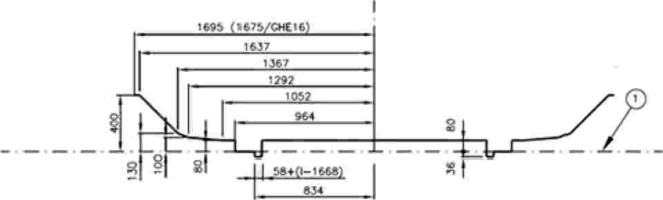
|
(1) |
Running surface. |
P.2. ASSOCIATED RULES
Table 46 shows the additional overthrows for gauges GEI1 and GEI2.
Table 46
Rules for additional overthrows S for gauges GEI1 and GEI2
|
Additional overthrows for track gauge ‘l’ and height ‘h’ compared to the running surface |
|
|
Radius |
h ≤ 0,4 m |
|
250 ≤ R < ∞ |
|
|
150 ≤ R < 250 |
|
P.3. VERTICAL LOWERING
The heights of the lower part must be reduced by the value 50/Rv (m), the radius being in metres.
The vertical curve radius Rv is limited to 500 m. Heights not exceeding 80 mm shall be considered as zero within a radius Rv between 500 m and 625 m
Appendix Q
National technical rules for UK-GB Specific Cases
The National Technical Rules for UK-GB specific cases referred to in point 7.7.17 of this TSI are contained in the documents listed in Table 47. All documents are available on www.rgsonline.co.uk.
Table 47
Notified national technical rules for UK-GB Specific Cases
|
Specific Case |
TSI Point |
Requirement |
NTR Ref |
NTR Title |
|
7.7.17.1 |
4.2.1: Table 2 & Table 3 |
Categories of line: Gauge |
GC/RT5212 |
Requirements for Defining and Maintaining Clearances |
|
GE/RT8073 |
Requirements for the Application of Standard Vehicle Gauges |
|||
|
GI/RT7016 |
Interface between Station Platforms, Track and Trains |
|||
|
7.7.17.2 & 7.7.17.8 |
4.2.3.1 & 6.2.4.1 |
Structure gauge |
GC/RT5212 |
Requirements for Defining and Maintaining Clearances |
|
GE/RT8073 |
Requirements for the Application of Standard Vehicle Gauges |
|||
|
GI/RT7016 |
Interface between Station Platforms, Track and Trains |
|||
|
7.7.17.3 & 7.7.17.9 |
4.2.3.2: Table 4 & 6.2.4.2 |
Distance between track centres |
GC/RT5212 |
Requirements for Defining and Maintaining Clearances |
|
7.7.17.4 |
4.2.5.3 & Annex J |
Maximum unguided length of fixed obtuse crossings |
GC/RT5021 |
Track System Requirements |
|
GM/RT2466 |
Railway Wheelsets |
|||
|
7.7. 17.6 |
4.2.9.2 |
Platform height |
GI/RT7016 |
Interface between Station Platforms, Track and Trains |
|
7.7. 17.7 & 7.7. 17.10 |
4.2.9.3 & 6.2.4.11 |
Platform offset |
GI/RT7016 |
Interface between Station Platforms, Track and Trains |
|
GC/RT5212 |
Requirements for Defining and Maintaining Clearances |
Appendix R
List of open points
|
(1) |
Requirements for the design of track, including switches and crossings, which are compatible with the use of eddy current braking systems (4.2.6.2.2) |
|
(2) |
Minimum factor alpha (a) for Traffic codes P1520 and F1520 (4.2.7.1.1) |
|
(3) |
Immediate action limits for isolated defects in alignment for speeds of more than 300 km/h (4.2.8.1) |
|
(4) |
Immediate action limits for isolated defects in longitudinal level for speeds of more than 300 km/h (4.2.8.2) |
|
(5) |
The minimum allowed value of distance between track centres for the uniform structure gauge IRL3 is an open point (7.7.18.2) |
|
(6) |
EN Line Category –Associated Speed [km/h] for Traffic codes P1, P2, P3a, P4a, P1520, P1600, F1520 and F1600 (Appendix E, Tables 38 and 39) |
|
(7) |
EN Line Category –Associated Speed [km/h] for Traffic codes P1, P2, P1600 and F1600 (Appendix F, Tables 40 and 41) |
|
(8) |
Rules and drawings related to gauges IRL1, IRL2 and IRL3 are an open point (Appendix O) |
|
(9) |
Requirements for mitigating the risk related to the ‘ballast pick up’ phenomenon (point 4.2.10.3) (open point also in the LOC&PAS TSI) |
Appendix S
Glossary
Table 48
Terms
|
Defined term |
TSI point |
Definition |
|
Actual point (RP)/ Praktischer Herzpunkt/ Pointe de coeur |
4.2.8.6 |
Physical end of a crossing vee. See Figure 2, which shows the relationship between the actual point (RP) and the intersection point (IP). |
|
Alert limit/ Auslösewert/ Limite d'alerte |
4.5.2 |
Refers to the value which, if exceeded, requires that the track geometry condition is analysed and considered in the regularly planned maintenance operations. |
|
Axle load/ Achsfahrmasse/ Charge à l'essieu |
4.2.1, 4.2.6.1 |
Sum of the static vertical wheel forces exerted on the track through a wheelset or a pair of independent wheels divided by acceleration of gravity. |
|
Braking systems independent of wheel-rail adhesion conditions' |
4.2.6.2.2 |
|
|
Cant/ Überhöhung/ Dévers de la voie |
4.2.4.2 4.2.8.5 |
Difference in height, relative to the horizontal, of the two rails of one track at a particular location, measured at the centrelines of the heads of the rails. |
|
Cant deficiency/Überhöhungsfehlbetrag/Insuffisance de devers |
4.2.4.3 |
Difference between the applied cant and a higher equilibrium cant. |
|
Common crossing/ Starres Herzstück/ Coeur de croisement |
4.2.8.6 |
Arrangement ensuring intersection of two opposite running edges of turnouts or diamond crossings and having one crossing vee and two wing rails. |
|
Crosswind/ Seitenwind/ Vents traversiers |
4.2.10.2 |
Strong wind blowing laterally to a line which may adversely affect the safety of trains running. |
|
Design value/ Planungswert/ Valeur de conception |
4.2.3.4, 4.2.4.2, 4.2.4.5, 4.2.5.1, 4.2.5.3 |
Theoretical value without manufacturing, construction or maintenance tolerances. |
|
Design track gauge/ Konstruktionsspurweite/ Ecartement de conception de la voie |
5.3.3 |
A single value which is obtained when all the components of the track conform precisely to their design dimensions or their median design dimension when there is a range. |
|
Distance between track centres/ Gleisabstand/ Entraxe de voies |
4.2.3.2 |
The distance between points of the centre lines of the two tracks under consideration, measured parallel to the running surface of the reference track namely the less canted track. |
|
Dynamic lateral force/Dynamische Querkraft/ Effort dynamique transversal |
4.2.6.3 |
The sum of dynamic forces exerted by a wheelset on the track in lateral direction. |
|
Earthworks/ Erdbauwerke/ Ouvrages en terre |
4.2.7.2, 4.2.7.4 |
Soil structures and soil-retaining structures that are subject to railway traffic loading. |
|
EN Line Category/ EN Streckenklasse/ EN Catégorie de ligne |
4.2.7.4, Appendix E |
The result of the classification process set out in EN 15528:2008+A1:2012 Annex A and referred to in that standard as ‘Line Category’. It represents the ability of the infrastructure to withstand the vertical loads imposed by vehicles on the line or section of line for regular service. |
|
Equivalent conicity/ Äquivalente Konizität/ Conicité équivalente |
4.2.4.5, 4.2.11.2 |
The tangent of the cone angle of a wheelset with coned wheels whose lateral movement has the same kinematic wavelength as the given wheelset on straight track and large-radius curves. |
|
Fixed nose protection/ Leitweite/ Cote de protection de pointe |
4.2.5.3, Appendix J |
Dimension between the crossing nose and check rail (see dimension No 2 on Figure 14 below). |
|
Flangeway depth/ Rillentiefe/ Profondeur d'ornière |
4.2.8.6. |
Dimension between the running surface and the bottom of flangeway (see dimension No 6 on Figure 14 below). |
|
Flangeway width/ Rillenweite/ Largeur d'ornière |
4.2.8.6. |
Dimension between a running rail and an adjacent check or wing rail (see dimension No 5 on Figure 14 below). |
|
Free wheel passage at check rail/wing rail entry/ Freier Raddurchlauf im Radlenker-Einlauf/Flügelschienen-Einlauf/Côte d'équilibrage du contre-rail |
4.2.8.6. |
Dimension between the working face of the crossing check rail or wing rail and the gauge face of the running rail opposite across the gauge measured at entry to check rail or wing rail respectively. (see dimensions No 4 on Figure 14 below). The entry to the check rail or wing rail is the point at which the wheel is allowed to contact the check rail or wing rail. |
|
Free wheel passage at crossing nose/ Freier Raddurchlauf im Bereich der Herzspitze/ Cote de libre passage dans le croisement |
4.2.8.6. |
Dimension between the working face of the crossing wing rail and check rail opposite across the gauge (see dimension No 3 on Figure 14 below). |
|
Free wheel passage in switches/Freier Raddurchlauf im Bereich der Zungen-vorrichtung/Côte de libre passage de l'aiguillage |
4.2.8.6. |
Dimension from the gauge face of one switch rail to the back edge of the opposite switch rail (see dimension No 1 on Figure 14 below). |
|
Gauge/ Begrenzungslinie/ Gabarit |
4.2.1, 4.2.3.1 |
Set of rules including a reference contour and its associated calculation rules allowing definition of the outer dimensions of the vehicle and the space to be cleared by the infrastructure. |
|
HBW/HBW/HBW |
5.3.1.2 |
The non SI unit for steel hardness defined in EN ISO 6506-1:2005 Metallic materials — Brinell hardness test. Test method. |
|
Height of check rail/ Radlenkerüberhöhung/ Surélévation du contre rail |
4.2.8.6, Appendix J |
Height of the check rail above the running surface (see dimension 7 on Figure 14 below). |
|
Immediate Action Limit/Soforteingriffsschwelle/ Limite d'intervention immédiate |
4.2.8, 4.5 |
The value which, if exceeded, requires taking measures to reduce the risk of derailment to an acceptable level. |
|
Infrastructure Manager/ Betreiber der Infrastruktur/ Gestionnaire de l'Infrastructure |
4.2.5.1, 4.2.8.3, 4.2.8.6, 4.2.11.2 4.4, 4.5.2, 4.6, 4.7, 6.2.2.1, 6.2.4, 6.4 |
As defined in Article 2h) of Directive 2001/14/EC of 26 February 2001 on the allocation of railway infrastructure capacity and the levying of charges for the use of railway infrastructure and safety certification (OJ L 75, 15.3.2001, p. 29). |
|
In service value/ Wert im Betriebszustand/ Valeur en exploitation |
4.2.8.5, 4.2.11.2 |
Value measured at any time after the infrastructure has been placed into service. |
|
Intersection point (IP)/ Theoretischer Herzpunkt/ Point d'intersection théorique |
4.2.8.6 |
Theoretical intersection point of the running edges at the centre of the crossing (see Figure 2). |
|
Intervention Limit/Eingriffsschwelle/ Valeur d'intervention |
4.5.2 |
The value, which, if exceeded, requires corrective maintenance in order that the immediate action limit shall not be reached before the next inspection; |
|
Isolated defect/ Einzelfehler/ Défaut isolé |
4.2.8 |
A discrete track geometry fault. |
|
Line speed/ Streckengeschwindigkeit/ Vitesse de la ligne |
4.2.1 |
Maximum speed for which a line has been designed. |
|
Maintenance file/ Instandhaltungsdossier/ Dossier de maintenance |
4.5.1 |
Elements of the technical file relating to conditions and limits of use and instructions for maintenance. |
|
Maintenance plan/ Instandhaltungsplan/ Plan de maintenance |
4.5.2 |
A series of documents setting out the infrastructure maintenance procedures adopted by an Infrastructure Manager. |
|
Multi-rail track/ Mehrschienengleis/ Voie à multi écartement |
4.2.2.2 |
Track with more than two rails, where at least two pairs of respective rails are designed to be operated as separate single tracks, with or without different track gauges. |
|
Nominal track gauge/Nennspurweite/ Ecartement nominal de la voie |
4.2.4.1 |
A single value which identifies the track gauge but may differ from the design track gauge. |
|
Normal service/ Regelbetrieb/ Service régulier |
4.2.2.2 4.2.9 |
The railway operating to a planned timetable service. |
|
Passive provision/ Vorsorge für künftige Erweiterungen/Réservation pour extension future |
4.2.9 |
Provision for the future construction of a physical extension to a structure (for example: increased platform length). |
|
Performance Parameter/ Leistungskennwert/ Paramètre de performance |
4.2.1 |
Parameter describing a TSI Category of Line used as the basis for the design of infrastructure subsystem elements and as the indication of the performance level of a line. |
|
Plain line/ Freie Strecke/ Voie courante |
4.2.4.5 4.2.4.6 4.2.4.7 |
Section of track without switches and crossings. |
|
Point retraction/ Spitzenbeihobelung/ Dénivelation de la pointe de cœur |
4.2.8.6 |
The reference line in a fixed common crossing can deviate from the theoretical reference line. From a certain distance to the crossing point, the reference line of the vee can, depending on the design, be retracted from this theoretical line away from the wheel flange in order to avoid contact between both elements. This situation is described in Figure 2. |
|
Rail inclination/Schienenneigung/ Inclinaison du rail |
4.2.4.5 4.2.4.7 |
An angle defining the inclination of the head of a rail when installed in the track relative to the plane of the rails (running surface), equal to the angle between the axis of symmetry of the rail (or of an equivalent symmetrical rail having the same rail head profile) and the perpendicular to the plane of the rails. |
|
Rail pad/ Schienenzwischenlage/ Semelle sous rail |
5.3.2 |
A resilient layer fitted between a rail and the supporting sleeper or baseplate. |
|
Reverse curve/ Gegenbogen/ Courbes et contre-courbes |
4.2.3.4 |
Two abutting curves of opposite flexure or hand |
|
Structure gauge/ Lichtraum/ Gabarit des obstacles |
4.2.3.1 |
Defines the space in relation to the reference track that shall be cleared of all objects or structures and of the traffic on the adjacent tracks, in order to allow safe operation on the reference track. It is defined on the basis of the reference contour by application of the associated rules. |
|
Swing nose |
4.2.5.2 |
|
|
Switch/ Zungenvorrichtung/ aiguillage |
4.2.8.6 |
A unit of track comprising two fixed rails (stock rails) and two movable rails (switch rails) used to direct vehicles from one track to another track. |
|
Switches and crossings/ Weichen und Kreuzungen/ Appareil de voie |
4.2.4.5, 4.2.4.7, 4.2.5, 4.2.6, 4.2.8.6, 5.2, 6.2.4.4, 6.2.4.8, 6.2.5.2, 7.3.3, Appendix C and D, |
Track constructed from sets of switches and individual crossings and the rails connecting them. |
|
Through route/ Stammgleis/ Voie directe |
Appendix D |
In the context of switches and crossings a route which perpetuate the general alignment of the track. |
|
Track design |
4.2.6, 6.2.5, Appendix C and D |
The track design consists of cross-section defining basic dimensions and track components (for example rail, rail fastenings, sleepers, ballast) used together with operating conditions with an impact on forces related to 4.2.6., such as axle load, speed and radius of horizontal curvature. |
|
Track gauge/ Spurweite/ Ecartement de la voie |
4.2.4.1, 4.2.4.5, 4.2.8.4, 5.3.3, 6.1.5.2, 6.2.4.3, Appendix H |
The smallest distance between lines perpendicular to the running surface intersecting each rail head profile in a range from 0 to 14 mm below the running surface. |
|
Track twist/ Gleisverwindung/ Gauche |
4.2.7.1.6 4.2.8.3, 6.2.4.9, |
Track twist is defined as the algebraic difference between two cross levels taken at a defined distance apart, usually expressed as a gradient between the two points at which the cross level is measured. |
|
Train length/ Zuglänge/ Longueur du train |
4.2.1 |
The length of a train, which can run on a certain line in normal operation. |
|
Unguided length of an obtuse crossing/ Führungslose Stelle/ Lacune dans la traversée |
4.2.5.3, Appendix J |
Portion of obtuse crossing where there is no guidance of the wheel described as ‘unguided distance’ in EN 13232-3:2003. |
|
Usable length of a platform/Bahnsteignutzlänge/ Longueur utile de quai |
4.2.1, 4.2.9.1 |
The maximum continuous length of that part of platform in front of which a train is intended to remain stationary in normal operating conditions for passengers to board and alight from the train, making appropriate allowance for stopping tolerances. Normal operating conditions means that railway is operating in a non-degraded mode (e.g. rail adhesion is normal, signals are working, everything is working as planned). |
Figure 14
Geometry of switches and crossings

|
(1) |
1 Free wheel passage in switches |
|
(2) |
Fixed nose protection |
|
(3) |
Free wheel passage at crossing nose |
|
(4) |
Free wheel passage at check rail/wing rail entry |
|
(5) |
Flangeway width |
|
(6) |
Flangeway depth |
|
(7) |
Height of check rail |
Appendix T
List of referenced standards
Table 49
List of referenced standards
|
Index No. |
Reference |
Document name |
Version (year) |
BP(s) concerned |
|
1 |
EN 13674-1 |
Railway applications — Track — Rail Part 1: Vignole railway rails 46 kg/m and above |
2011 |
Railhead profile for plain line (4.2.4.6), Assessment of rails (6.1.5.1) |
|
2 |
EN 13674-4 |
Railway applications — Track — Rail — Part 4: Vignole railway rails from 27 kg/m to, but excluding 46 kg/m (with Amendment A1:2009) |
2006 |
Railhead profile for plain line (4.2.4.6) |
|
3 |
EN 13715 |
Railway applications — Wheelsets and boogies — Wheels — Wheels tread (with Amendment A1:2010) |
2006 A1:2010 |
Equivalent conicity (4.2.4.5) |
|
4 |
EN 13848-1 |
Track geometry quality — Part 1: Characterisation of track geometry (with Amendment A1:2008) |
2003 |
The immediate action limit for track twist (4.2.8.3), Assessment of minimum value of mean track gauge (6.2.4.5) |
|
5 |
EN 13848-5 |
Railway applications — Track — Track geometry quality — Part 5: Geometric quality levels — Plain line (with Amendment A1:2010) |
2008 |
The immediate action limit for alignment (4.2.8.1), The immediate action limit for longitudinal level (4.2.8.2), The immediate action limit for track twist (4.2.8.3) |
|
6 |
EN 14067-5 |
Railway applications — Aerodynamics — Part 5: Requirements and test procedures for aerodynamics in tunnels (with Amendment A1:2010) |
2006 |
Assessment of maximum pressure variations in tunnels (6.2.4.12) |
|
7 |
EN 15273-3 |
Railway applications — Gauges — Part 3: Structure gauges |
2013 |
Structure gauge (4.2.3.1), Distance between track centres (4.2.3.2), Platform offset (4.2.9.3), Assessment of structure gauge (6.2.4.1), Assessment of distance between track centres (6.2.4.2), Assessment of platform offset (6.2.4.11) |
|
8 |
EN 15302 |
Railway applications — Method for specifying the equivalent conicity (with Amendment A1:2010) |
2008 |
Equivalent conicity (4.2.4.5), Assessment of design values for equivalent conicity (6.2.4.6) |
|
9 |
EN 15528 |
Railway applications — Line categories for managing the interface between load limits of vehicles and infrastructure (with Amendment A1:2012) |
2008 |
Ascertain compatibility of infrastructure and rolling stock after authorisation of rolling stock (7.6), Capability requirements for structures according to traffic code (Appendix E), Basis of minimum requirements for structures for passenger coaches and multiple units (Appendix K), Definition of line category a12 for traffic code p6 (Appendix L) |
|
10 |
EN 15663 |
Railway applications — Definition of vehicle reference masses (with Corrections AC:2010) |
2009 |
TSI categories of line (4.2.1), Basis of minimum requirements for structures for passenger coaches and multiple units (Appendix K) |
|
11 |
EN 1990 |
Eurocode — Basis of structural design (with Amendment A1:2005 and Correction AC:2010) |
2002 |
Structures resistance to traffic loads (4.2.7), Resistance of new bridges to traffic loads (4.2.7.1) |
|
12 |
EN 1991-2 |
Eurocode 1 — Actions on structures — Part 2: Traffic load on bridges (with Correction AC:2010) |
2003 |
Structures resistance to traffic loads (4.2.7), Resistance of new bridges to traffic loads (4.2.7.1), Equivalent vertical loading for new earthworks and earth pressure effects (4.2.7.2), Resistance of new structures over or adjacent to tracks (4.2.7.3) |
|
13 |
EN 14363:2005 |
Railway applications — Testing for the acceptance of running characteristics of railway vehicles — Testing of running behaviour and stationary tests |
2005 |
Track resistance to vertical load (4.2.6.1), Lateral track resistance (4.2.6.3), |
|
12.12.2014 |
EN |
Official Journal of the European Union |
L 356/110 |
COMMISSION REGULATION (EU) No 1300/2014
of 18 November 2014
on the technical specifications for interoperability relating to accessibility of the Union's rail system for persons with disabilities and persons with reduced mobility
(Text with EEA relevance)
THE EUROPEAN COMMISSION,
Having regard to the Treaty on the Functioning of the European Union,
Having regard to Directive 2008/57/EC of the European Parliament and of the Council of 17 June 2008 on the interoperability of the rail system within the Community (1), and in particular Articles 6(1) and 8(1) thereof,
Whereas:
|
(1) |
Article 12 of Regulation (EC) No 881/2004 of the European Parliament and of the Council (2) requires the European Railway Agency (the Agency) to ensure that the technical specifications for interoperability (TSIs) are adapted to technical progress, market trends and social requirements and to propose to the Commission any amendments to the TSIs which it considers necessary. |
|
(2) |
By Decision C(2010) 2576 (3), the Commission gave the Agency a mandate to develop and review the technical specifications for interoperability with a view to extending their scope to the entire rail system in the Union. Under the terms of that mandate, the Agency was asked to extend the scope of the TSI relating to accessibility of the trans-European conventional and high-speed rail system provided for by Commission Decision 2008/164/EC (4) for persons with disabilities and persons with reduced mobility to the entire rail system throughout the Union. |
|
(3) |
On 6 May 2013 the Agency submitted a recommendation on the adoption of the TSI relating to persons with reduced mobility. |
|
(4) |
The United Nations Convention on the Rights of Persons with Disabilities, to which the Union and most Member States are party, recognises accessibility as one of its general principles. It requires, in Article 9, States Parties to take appropriate measures to ensure that persons with disabilities have access on an equal basis with others. These measures must include the identification and elimination of obstacles and barriers to accessibility and apply, inter alia, to transportation. |
|
(5) |
Directive 2008/57/EC establishes ‘accessibility’ as an essential requirement of the rail system within the Union. |
|
(6) |
Directive 2008/57/EC provides for a register of infrastructure and registers of vehicles, indicating the main parameters, to be published and updated on a regular basis. Commission Decision 2008/164/EC further defines the parameters for the TSI relating to ‘persons with reduced mobility’ to be included in these registers. As the objectives of these registers are linked to the authorisation procedure and technical compatibility, it is considered necessary to establish a separate tool for these parameters. This inventory of assets should enable obstacles and barriers to accessibility to be identified and their progressive elimination to be monitored. |
|
(7) |
Directive 2008/57/EC establishes the principle of gradual implementation, in particular providing that target subsystems indicated in a TSI may be set in place gradually within a reasonable timescale and that each TSI should indicate an implementation strategy with a view to making a gradual transition from the existing situation to the final situation in which compliance with the TSI will be the norm. |
|
(8) |
With a view to progressively eliminating within a reasonable timescale, all identified barriers to accessibility by way of a coordinated effort to renew and upgrade subsystems and by deploying operational measures, Member States should establish national implementation plans. However, since these national implementation plans cannot be in sufficient detail and are subject to unpredictable changes, Member States should continue to submit information in cases when placing in service of existing subsystems after renewal or upgrading requires a new authorisation for placing in service and if the TSI is not fully applied in accordance with Directive 2008/57/EC. |
|
(9) |
The Union should adopt common priorities and criteria which Member States should integrate in their national implementation plans. This will contribute to achieving progressive implementation of the TSI within a reasonable timescale. |
|
(10) |
In order to follow technological evolution and encourage modernization, innovative solutions should be promoted and their implementation should, under certain conditions, be allowed. Where an innovative solution is proposed, the manufacturer or his authorized representative should explain how they deviate from the relevant section of the TSI, and the innovative solution should be assessed by the Commission. If this assessment is positive, the Agency should define the appropriate functional and interface specifications of the innovative solution and develop the appropriate assessment methods. |
|
(11) |
In order to prevent unnecessary additional costs and administrative burden and in order not to interfere with existing contracts, Decision 2008/164/EC should continue to apply to subsystems and projects referred to in Article 9(1)(a) of Directive 2008/57/EC after its repeal. |
|
(12) |
The measures provided for in this Regulation are in accordance with the opinion of the Committee established under Article 29(1) of Directive 2008/57/EC, |
HAS ADOPTED THIS REGULATION:
Article 1
Subject matter
This Regulation establishes the technical specification for interoperability (TSI) relating to accessibility of the Union's rail system for persons with disabilities and persons with reduced mobility, as set out in the Annex.
Article 2
Scope
1. The TSI shall apply to the infrastructure, operation and traffic management, telematics applications and rolling stock subsystems as described in point 2 of Annex II to Directive 2008/57/EC and in point 2.1 of the Annex to this Regulation. It shall cover all aspects of these subsystems which are relevant to accessibility for persons with disabilities and persons with reduced mobility.
2. The TSI shall apply to the following networks:
|
(a) |
the trans-European conventional rail system network as defined in Annex I, section 1.1 of Directive 2008/57/EC; |
|
(b) |
the trans-European high-speed rail system network as defined in Annex I, section 2.1 of Directive 2008/57/EC; |
|
(c) |
all other parts of the network. |
The TSI shall not cover the cases referred to in Article 1(3) of Directive 2008/57/EC.
3. The TSI shall apply to all new infrastructure or rolling stock subsystems of the rail system in the Union, referred to in paragraph 1, which is placed in service after the date of application provided for in Article 12, account being taken of points 7.1.1 and 7.1.2 of the Annex.
4. The TSI shall not apply to existing infrastructure or rolling stock of the rail system in the Union, referred to in paragraph 1, which is already placed in service on the network (or part of it) of any Member State at the date of application provided for in Article 12.
5. However, the TSI shall apply to existing infrastructure and rolling stock of the rail system in the Union, referred to in paragraph 1, when it is subject to renewal or upgrading in accordance with Article 20 of Directive 2008/57/EC, having regard to Article 8 of this Regulation and point 7.2 of the Annex to this Regulation.
Article 3
Conformity assessment
1. The procedures for conformity assessment of interoperability constituents and subsystems set out in Section 6 of the Annex shall be based on the modules established in Commission Decision 2010/713/EU (5).
2. The type or design examination certificate of interoperability constituents shall be valid for a five year period. During that period, new constituents of the same type are permitted to be placed into service without a new conformity assessment.
3. Certificates referred to in paragraph 2 which have been issued according to the requirements of Decision 2008/164/EC remain valid, without a need for a new conformity assessment, until the expiry date originally established. In order to renew a certificate the design or type shall be re-assessed only against new or modified requirements set out in the Annex to this Regulation.
4. Universal toilet modules which have been assessed against the requirements of Commission Decision 2008/164/EC shall not be re-assessed when they are intended for rolling stock of an existing design as defined in Commission Regulation (EU) No 1302/2014 (6).
Article 4
Specific cases
1. With regard to specific cases referred to in Section 7.3 of the Annex, the conditions to be met for the verification of interoperability in accordance with Article 17(2) of Directive 2008/57/EC shall be the applicable technical rules in use in the Member State which authorises the placing in service of the subsystems covered by this Regulation.
2. By 1 July 2015, each Member State shall inform the other Member States and the Commission about:
|
(a) |
the technical rules referred to in paragraph 1; |
|
(b) |
the conformity assessment and verification procedures to be carried out with a view to applying the national rules referred to in paragraph 1; |
|
(c) |
the bodies designated in accordance with Article 17, paragraph 3, of Directive 2008/57/EC appointed to carry out the conformity assessment and verification procedures with respect to the specific cases set out in Section 7.3 of the Annex. |
Article 5
Projects at an advanced stage of development
In accordance with Article 9(3) of Directive 2008/57/EC, each Member State shall communicate to the Commission, within one year of the entry into force of this Regulation, a list of projects being implemented within its territory and that are at an advanced stage of development.
Article 6
Innovative solutions
1. Technological progress may require innovative solutions, which do not comply with the specifications set out in the Annex or for which the assessment methods set out in the Annex cannot be applied.
2. Innovative solutions may concern the infrastructure and rolling stock subsystems, their parts and their interoperability constituents.
3. If an innovative solution is proposed, the manufacturer or his authorised representative established within the Union shall state how it deviates from the relevant provision of the TSI set out in the Annex and submit it to the Commission for analysis. The Commission may request the Agency's opinion on the proposed innovative solution and, where appropriate, may consult relevant stakeholders.
4. The Commission shall deliver an opinion on the proposed innovative solution. If this opinion is positive, the appropriate functional and interface specifications and the assessment method needed in the TSI to enable use to be made of this innovative solution shall be developed and subsequently incorporated in the TSI during the revision process. If the opinion is negative, the innovative solution proposed cannot be applied.
5. Pending the revision of the TSI, the positive opinion delivered by the Commission shall be considered as acceptable means of compliance with the essential requirements of Directive 2008/57/EC and may be used for the assessment of subsystems and projects.
Article 7
Inventory of Assets
1. Each Member State shall ensure that an inventory of assets is established and implemented with a view to:
|
(a) |
identifying barriers to accessibility; |
|
(b) |
providing information to users; |
|
(c) |
monitoring and evaluating progress on accessibility. |
2. The Agency shall set up and run a working party in charge of making a proposal for a recommendation as regards the minimum structure and content of data to be collected for the inventories of assets. The Agency shall submit a recommendation to the Commission, including on content, data format, functional and technical architecture, operating mode, rules for data input and consultation, and rules for self-assessment and designation of the entities responsible for data provision. In order to identify the most viable solution, the recommendation shall take into account the estimated costs and benefits of all the technical solutions considered. It shall include a proposal for the timing of the establishment of the inventories of assets.
3. On the basis of the recommendation referred to in paragraph 2, chapter 7 of the Annex shall be updated in accordance with Article 6 of Directive 2008/57/EC.
4. The scope of these inventories of assets shall extend at least to:
|
(a) |
public areas of stations dedicated to the transport of passengers as defined in point 2.1.1 of the Annex; |
|
(b) |
rolling stock as defined in point 2.1.2 of the Annex. |
5. The inventory of assets shall be updated to incorporate data on new infrastructure and rolling stock and on renewal or upgrading work done to existing infrastructure and rolling stock.
Article 8
National Implementation Plans
1. Member States shall adopt national implementation plans, including at least the information listed in Appendix C of the Annex, with a view to progressively eliminating all identified barriers to accessibility.
2. The national implementation plans shall be based on existing national plans and, subject to availability, on the inventory of assets referred to in Article 7, or on any other relevant and reliable source of information.
The scope and speed of implementing national plans shall be decided by Member States.
3. The national implementation plans shall run over a period of at least 10 years and shall be updated regularly, at least every five years.
4. The national implementation plans shall contain a strategy, including a prioritisation rule laying down the criteria and priorities for stations and units of rolling stock to be designated for renewal or upgrading. This strategy shall be formulated in cooperation with infrastructure manager(s), station manager(s), railway undertaking(s) and, if needed, other local authorities (including local transport authorities). Representative associations of users including disabled persons and persons with reduced mobility shall be consulted.
5. In each Member State, the prioritisation rule referred to in paragraph 4 shall replace the rule set out in Appendix B of the Annex which shall apply until the adoption of the national implementation plan in that Member State.
6. Member States shall notify their national implementation plans to the Commission no later than 1 January 2017. The Commission shall publish the national implementation plans, and any subsequent revisions notified according to paragraph 9, on its website and inform Member States about them through the Committee established by Directive 2008/57/EC.
7. Within six months of completion of the notification process, the Commission shall draw up a comparative overview of the strategies contained in the national implementation plans. On the basis of this overview, and in cooperation with the advisory body referred to in Article 9, it shall identify common priorities and criteria to further the implementation of the TSI. These priorities shall be integrated in chapter 7 of the Annex during the revision process pursuant to Article 6 of Directive 2008/57/EC.
8. Member States shall revise their national implementation plans in accordance with the priorities referred to in paragraph 7 within 12 months of the adoption of the revised TSI.
9. Member States shall notify the revised national implementation plans referred to in paragraph 8 and any other updates of the national implementation plans referred to in paragraph 3 to the Commission not later than four weeks after their approval.
Article 9
Advisory body
1. The Commission shall establish an advisory body to assist the Commission in closely monitoring implementation of the TSI. This advisory body shall be chaired by the Commission.
2. The advisory body shall be established no later than 1 February 2015, and shall consist of:
|
(a) |
Member States wishing to participate; |
|
(b) |
representative bodies from the railway sector; |
|
(c) |
representative bodies of users; |
|
(d) |
the European Railway Agency. |
3. The tasks of the advisory body shall include:
|
(a) |
monitoring the development of a minimum data structure for the inventory of assets, |
|
(b) |
supporting Member States in the completion of their inventories of assets and implementation plans, |
|
(c) |
assisting the Commission in monitoring implementation of the TSI, |
|
(d) |
facilitating exchanges of best practices, |
|
(e) |
assisting the Commission in identifying the common priorities and criteria for the implementation of the TSI as referred to in Article 8. |
|
(f) |
where appropriate, making recommendations to the Commission, in particular for strengthening implementation of the TSI. |
4. The Commission shall keep Member States informed of the activities of the advisory body through the Committee established by Directive 2008/57/EC.
Article 10
Final provisions
Full compliance with the TSI is mandatory for projects which receive the Union financial support for the renewal or upgrading of existing rolling stock or parts thereof or for the renewal or upgrading of existing infrastructure, in particular a station or components thereof and platforms or components thereof.
Article 11
Repeal
Decision 2008/164/EC is repealed with effect from 1 January 2015.
It shall however continue to apply to:
|
(a) |
subsystems authorised in accordance with that Decision; |
|
(b) |
projects for new, renewed or upgraded subsystems which, at the date of publication of this Regulation, are at an advanced stage of development or are the subject of an ongoing contract; |
|
(c) |
projects for new rolling stock of an existing design, as referred to in point 7.1.2 of the Annex to this Regulation. |
Article 12
Entry into force
This Regulation shall enter into force on the twentieth day following that of its publication in the Official Journal of the European Union.
It shall apply from 1 January 2015. However, an authorisation for placing in service may be granted in accordance with the TSI as set out in the Annex to this Regulation before 1 January 2015.
This Regulation shall be binding in its entirety and directly applicable in all Member States.
Done at Brussels, 18 November 2014.
For the Commission
The President
Jean-Claude JUNCKER
(1) OJ L 191, 18.7.2008, p. 1.
(2) Regulation (EC) No 881/2004 of the European Parliament and of the Council of 29 April 2004 establishing a European railway agency (OJ L 164, 30.4.2004, p. 1).
(3) Commission Decision C(2010) 2576 final of 29 April 2010 concerning a mandate to the European Railway Agency to develop and review Technical Specifications for Interoperability with a view to extending their scope to the whole rail system in the European Union.
(4) Commission Decision 2008/164/EC of 21 December 2007 concerning the technical specification of interoperability relating to ‘persons with reduced mobility’ in the trans-European conventional and high-speed rail system (OJ L 64, 7.3.2008, p. 72).
(5) Commission Decision 2010/713/EU of 9 November 2010 on modules for the procedures for assessment of conformity, suitability for use and EC verification to be used in the technical specifications for interoperability adopted under Directive 2008/57/EC of the European Parliament and of the Council (OJ L 319, 4.12.2010, p. 1).
(6) Commission Regulation (EU) No 1302/2014 of 18 November 2014 concerning a technical specification for interoperability relating to the ‘rolling stock — locomotives and passenger rolling stock’ subsystem of the rail system in the European Union (see page 228 of this Official Journal).
ANNEX
TABLE OF CONTENTS
|
1. |
INTRODUCTION | 118 |
|
1.1. |
Technical scope | 118 |
|
1.2. |
Geographical scope | 118 |
|
2. |
SCOPE OF SUBSYSTEMS AND DEFINITIONS | 118 |
|
2.1. |
Scope of the subsystems | 118 |
|
2.1.1. |
Scope related to infrastructure subsystem | 118 |
|
2.1.2. |
Scope related to rolling stock subsystem | 118 |
|
2.1.3. |
Scope related to operational aspects subsystem | 118 |
|
2.1.4. |
Scope related to Telematics Applications for Passengers subsystem | 118 |
|
2.2. |
Definition of ‘person with disabilities and person with reduced mobility’ | 118 |
|
2.3. |
Other Definitions | 118 |
|
3. |
ESSENTIAL REQUIREMENTS | 119 |
|
4. |
CHARACTERISATION OF THE SUBSYSTEMS | 121 |
|
4.1. |
Introduction | 121 |
|
4.2. |
Functional and technical specifications | 122 |
|
4.2.1. |
Infrastructure Subsystem | 122 |
|
4.2.2. |
Rolling Stock Subsystem | 128 |
|
4.3. |
Functional and technical specifications of the interfaces | 139 |
|
4.3.1. |
Interfaces with the infrastructure subsystem | 139 |
|
4.3.2. |
Interfaces with the rolling stock subsystem | 139 |
|
4.3.3. |
Interfaces with the Telematics Applications for Passengers subsystem | 139 |
|
4.4. |
Operating rules | 140 |
|
4.4.1. |
Infrastructure subsystem | 140 |
|
4.4.2. |
Rolling Stock subsystem | 141 |
|
4.4.3. |
Provision of boarding aids and provision of assistance | 144 |
|
4.5. |
Maintenance rules | 144 |
|
4.5.1. |
Infrastructure Subsystem | 144 |
|
4.5.2. |
Rolling Stock Subsystem | 144 |
|
4.6. |
Professional qualifications | 144 |
|
4.7. |
Health and safety conditions | 145 |
|
4.8. |
Infrastructure and Rolling Stock registers | 145 |
|
4.8.1. |
Infrastructure register | 145 |
|
4.8.2. |
Rolling Stock register | 145 |
|
5. |
INTEROPERABILITY CONSTITUENTS | 145 |
|
5.1. |
Definition | 145 |
|
5.2. |
Innovative solutions | 145 |
|
5.3. |
List and characteristics of constituents | 145 |
|
5.3.1. |
Infrastructure | 145 |
|
5.3.2. |
Rolling stock | 147 |
|
6. |
ASSESSMENT OF CONFORMITY AND/OR SUITABILITY FOR USE | 150 |
|
6.1. |
Interoperability constituents | 150 |
|
6.1.1. |
Conformity assessment | 150 |
|
6.1.2. |
Application of modules | 151 |
|
6.1.3. |
Particular assessment procedures | 152 |
|
6.2. |
Subsystems | 152 |
|
6.2.1. |
EC verification (general) | 152 |
|
6.2.2. |
Procedures for EC verification of a subsystem (modules) | 153 |
|
6.2.3. |
Particular assessment procedures | 153 |
|
6.2.4. |
Technical solutions giving presumption of conformity at design stage | 153 |
|
6.2.5. |
Assessment of maintenance | 154 |
|
6.2.6. |
Assessment of operational rules | 154 |
|
6.2.7. |
Assessment of units intended to be used in general operation | 154 |
|
7. |
IMPLEMENTATION OF THE TSI | 154 |
|
7.1. |
Application of this TSI to new Infrastructure and Rolling Stock | 154 |
|
7.1.1. |
New Infrastructure | 154 |
|
7.1.2. |
New Rolling Stock | 155 |
|
7.2. |
Application of this TSI to existing Infrastructure and Rolling Stock | 155 |
|
7.2.1. |
Steps of the gradual transition to the target system | 155 |
|
7.2.2. |
Application of this TSI to existing Infrastructure | 155 |
|
7.2.3. |
Application of this TSI to existing rolling stock | 155 |
|
7.3. |
Specific cases | 156 |
|
7.3.1. |
General | 156 |
|
7.3.2. |
List of specific cases | 156 |
|
Appendix A: |
Standards or Normative Documents Referred to in this TSI | 160 |
|
Appendix B: |
Temporary prioritization rule for the upgrade/renewal of stations | 161 |
|
Appendix C: |
Information to be provided in a National Implementation Plan (NIP) | 162 |
|
Appendix D: |
Assessment of interoperability constituents | 163 |
|
Appendix E: |
Assessment of the subsystems | 164 |
|
Appendix F: |
Renewal or upgrade of rolling stock | 166 |
|
Appendix G: |
Passenger external doors audible warnings | 168 |
|
Appendix H: |
Diagrams of priority seats | 170 |
|
Appendix I: |
Diagrams of wheelchair spaces | 172 |
|
Appendix J: |
Diagrams of clearways | 174 |
|
Appendix K: |
Table of the corridor width for wheelchair accessible areas in Rolling Stock | 175 |
|
Appendix L: |
Reach zone of a wheelchair user | 176 |
|
Appendix M: |
Wheelchair transportable by train | 177 |
|
Appendix N: |
PRM Signage | 178 |
1. INTRODUCTION
The objective of this TSI is to enhance the accessibility of rail transport to persons with disabilities and persons with reduced mobility.
1.1. Technical scope
The technical scope of this TSI is defined in Article 2(1) of the Regulation.
1.2. Geographical scope
The geographical scope of this TSI is defined in Article 2(2) of the Regulation.
2. SCOPE OF SUBSYSTEMS AND DEFINITIONS
2.1. Scope of the subsystems
2.1.1. Scope related to infrastructure subsystem
This TSI applies to all the public areas of stations dedicated to the transport of passengers that are controlled by the railway undertaking, infrastructure manager or station manager. This includes the provision of information, the purchase of a ticket and its validation if needed, and the possibility to wait for the train.
2.1.2. Scope related to rolling stock subsystem
This TSI applies to rolling stock which is in the scope of the LOC&PAS TSI and which is intended to carry passengers.
2.1.3. Scope related to operational aspects subsystem
This TSI applies to the procedures enabling a coherent operation of the infrastructure and rolling stock subsystems when passengers are persons with disabilities and persons with reduced mobility.
2.1.4. Scope related to Telematics Applications for Passengers subsystem
This TSI applies to visual and audible passenger information systems located in stations and in rolling stock.
2.2. Definition of ‘person with disabilities and person with reduced mobility’
‘Person with disabilities and person with reduced mobility’ means any person who has a permanent or temporary physical, mental, intellectual or sensory impairment which, in interaction with various barriers, may hinder their full and effective use of transport on an equal basis with other passengers or whose mobility when using transport is reduced due to age.
The transport of oversized items (for example: bicycles and bulky luggage) is not within the scope of this TSI.
2.3. Other Definitions
Definitions related to rolling stock: refer to the LOC&PAS TSI point 2.2.
Obstacle-free route
An obstacle-free route is a link between two or more public areas dedicated to the transport of passengers such as specified in point 2.1.1. It can be navigated by all persons with disabilities and reduced mobility. In order to achieve this, the route can be divided to better meet the needs of all persons with disabilities and reduced mobility. The combination of all the parts of the obstacle free route constitutes the route accessible for all persons with disabilities and reduced mobility.
Step-free route
A step-free route is a division of an obstacle-free route that meets the needs of mobility impaired persons. Changes in level are avoided or, when they cannot be avoided, they are bridged via ramps or lifts.
‘Tactile Signs’ and ‘Tactile Controls’
‘Tactile signs’ and ‘tactile controls’ are signs or controls, which include raised pictograms, raised characters or Braille lettering.
Station Manager
The station manager is an organisational entity in a Member State, which has been made responsible for the management of a railway station and which may be the infrastructure manager.
Safety Information
Safety information is information that shall be given to passengers so that they know in advance how they have to behave in case of an emergency.
Safety Instructions
Safety instructions are the instructions that shall be given to passengers in case of an emergency so that they understand what to do.
Level access
A level access is an access from a platform to the doorway of a rolling stock for which it can be demonstrated that:
|
— |
The gap between the door sill of that doorway (or of the extended bridging plate of that doorway) and the platform does not exceed 75 mm measured horizontally and 50 mm measured vertically and |
|
— |
The rolling stock has no internal step between the door sill and the vestibule. |
3. ESSENTIAL REQUIREMENTS
The following tables indicate the essential requirements, as set out in Annex III of Directive 2008/57/EC that are met by the specifications set out in Section 4 of this TSI for the scope of this TSI.
The essential requirements that are not listed in the table are not relevant within the scope of this TSI.
Table 1
Essential requirements for the infrastructure subsystem
|
Infrastructure |
Reference to Essential Requirement in Annex III to Directive 2008/57/EC |
||||||
|
Element of the TSI Domain |
Reference point of this Annex |
Safety |
Reliability and Availability |
Health |
Environ-mental protection |
Technical compatibility |
Accessibility (1) |
|
Parking facilities for persons with disabilities and persons with reduced mobility |
4.2.1.1 |
|
|
|
|
|
2.1.2 |
|
Obstacle-free route |
4.2.1.2 |
2.1.1 |
|
|
|
|
2.1.2 |
|
Doors and entrances |
4.2.1.3 |
1.1.1 2.1.1 |
|
|
|
|
2.1.2 |
|
Floor surfaces |
4.2.1.4 |
2.1.1 |
|
|
|
|
2.1.2 |
|
Highlighting of transparent obstacles |
4.2.1.5 |
2.1.1 |
|
|
|
|
2.1.2 |
|
Toilets and baby-nappy changing facilities |
4.2.1.6 |
1.1.5 2.1.1 |
|
|
|
|
2.1.2 |
|
Furniture and free-standing devices |
4.2.1.7 |
2.1.1 |
|
|
|
|
2.1.2 |
|
Ticketing, information desks and customer assistance points |
4.2.1.8 |
2.1.1 |
2.7.3 |
|
|
2.7.1 |
2.1.2 2.7.5 |
|
Lighting |
4.2.1.9 |
2.1.1 |
|
|
|
|
2.1.2 |
|
Visual information: signposting, pictograms, printed or dynamic information |
4.2.1.10 |
|
|
|
|
2.7.1 |
2.1.2 2.7.5 |
|
Spoken information |
4.2.1.11 |
2.1.1 |
2.7.3 |
|
|
2.7.1 |
2.1.2 2.7.5 |
|
Platform width and edge of platform |
4.2.1.12 |
2.1.1 |
|
|
|
|
2.1.2 |
|
End of platform |
4.2.1.13 |
2.1.1 |
|
|
|
|
2.1.2 |
|
Boarding aids on platforms |
4.2.1.14 |
1.1.1 |
|
|
|
|
2.1.2 |
|
Level track crossing at stations |
4.2.1.15 |
2.1.1 |
|
|
|
|
2.1.2 |
Table 2
Essential requirements for the rolling stock subsystem
|
Rolling Stock |
Reference to Essential Requirement in Annex III of Directive 2008/57/EC |
||||||
|
Element of the TSI Domain |
Reference point of this Annex |
Safety |
Reliability and Availability |
Health |
Environ-mental protection |
Technical compatibility |
Accessibility |
|
Seats |
4.2.2.1 |
|
|
1.3.1 |
|
|
2.4.5 |
|
Wheelchair spaces |
4.2.2.2 |
2.4.1 |
|
|
|
|
2.4.5 |
|
Doors |
4.2.2.3 |
1.1.1 1.1.5 2.4.1 |
1.2 |
|
|
|
2.4.5 |
|
Lighting |
4.2.2.4 |
2.4.1 |
|
|
|
|
2.4.5 |
|
Toilets |
4.2.2.5 |
2.4.1 |
|
|
|
|
2.4.5 |
|
Clearways |
4.2.2.6 |
|
|
1.3.1 |
|
|
2.4.5 |
|
Customer information |
4.2.2.7 |
2.4.1 |
2.7.3 |
|
|
2.7.1 |
2.4.5 2.7.5 |
|
Height changes |
4.2.2.8 |
1.1.5 |
|
|
|
|
2.4.5 |
|
Handrails |
4.2.2.9 |
1.1.5 |
|
|
|
|
2.4.5 |
|
Wheelchair accessible sleeping accommodation |
4.2.2.10 |
2.4.1 |
|
|
|
|
2.4.5 |
|
Step position for vehicle access and egress |
4.2.2.11 |
1.1.1 |
2.4.2 |
|
|
1.5 2.4.3 |
2.4.5 |
|
Boarding aids |
4.2.2.12 |
1.1.1 |
|
|
|
1.5 2.4.3 |
2.4.5 |
4. CHARACTERISATION OF THE SUBSYSTEMS
4.1. Introduction
|
(1) |
The rail system of the Union, to which Directive 2008/57/EC applies and of which the subsystems are parts, is an integrated system whose consistency shall be verified. This consistency shall be checked in particular with regard to the specifications of each subsystem, its interfaces vis-à-vis the system in which it is integrated as well as the operating and maintenance rules. |
|
(2) |
The functional and technical specifications of the subsystems and their interfaces, described in points 4.2 and 4.3, do not impose the use of specific technologies or technical solutions, except where this is strictly necessary for the interoperability of the Union rail network. But innovative solutions for interoperability may require new specifications and/or new assessment methods. In order to allow technological innovation, these specifications and assessment methods shall be developed by the process described in article 6 of the Regulation. |
|
(3) |
Taking account of all the applicable essential requirements, the basic parameters related to accessibility for persons with disabilities and persons with reduced mobility are set out for the subsystems infrastructure and rolling stock in point 4.2 of this TSI. The operational requirements and responsibilities are set out in the OPE TSI and in point 4.4 of this TSI. |
4.2. Functional and technical specifications
4.2.1. Infrastructure Subsystem
|
(1) |
In light of the essential requirements in Section 3, the functional and technical specifications of the infrastructure subsystem related to accessibility for persons with disabilities and persons with reduced mobility are arranged as follows:
|
|
(2) |
The basic parameters that are specified in points 4.2.1.1 — 4.2.1.15 apply to the scope of the infrastructure subsystem that is defined in point 2.1.1; they can be divided into two categories:
The table 3 below indicates the category of each of the basic parameters. Table 3 Categories of basic parameters
|
4.2.1.1.
|
(1) |
Where a station specific parking area exists, there shall be sufficient and adapted parking spaces reserved for persons with disabilities and persons with reduced mobility eligible to utilise them at the nearest practicable position, within the parking area, to an accessible entrance. |
4.2.1.2.
|
(1) |
Obstacle free routes shall be provided that interconnect the following public areas of the infrastructure if provided:
|
|
(2) |
The length of the obstacle-free routes shall be the shortest practical distance. |
|
(3) |
Obstacle-free route floor surfaces and ground surfaces shall have low reflecting properties. |
4.2.1.2.1. Horizontal circulation
|
(1) |
All obstacle-free routes, footbridges and subways, shall have a free width of a minimum of 160 cm except in areas that are specified in points 4.2.1.3 (2) (doors), 4.2.1.12 (3) (platforms) and 4.2.1.15 (2) (level crossings)). |
|
(2) |
Where thresholds are installed on a horizontal route, they shall contrast with the surrounding floor and shall not be higher than 2,5 cm. |
4.2.1.2.2. Vertical circulation
|
(1) |
Where an obstacle-free route includes a change in level, there shall be a step-free route providing an alternative to stairs for mobility impaired people. |
|
(2) |
Staircases on the obstacle-free routes shall have a minimum width of 160 cm measured between the handrails. As a minimum the first and last steps shall be indicated by a contrasting band and as a minimum tactile warning surface indicators shall be installed before the first descending step. |
|
(3) |
Ramps shall be installed for persons with disabilities and persons with reduced mobility unable to use stairs where lifts are not provided. They shall have a moderate gradient. A steep gradient is allowed for ramps on short distances only. |
|
(4) |
Stairs and ramps shall be provided with handrails on both sides and at two levels. |
|
(5) |
Lifts shall be provided where ramps are not available and shall be at least of type 2 in accordance with the specification referenced in Appendix A, index 1. Type 1 lifts are allowed in the case of stations being renewed or upgraded only. |
|
(6) |
Escalators and moving walks shall be designed in accordance with the specification referenced in Appendix A, index 2. |
|
(7) |
Level track crossings can form part of an obstacle-free route when they comply with the requirements of point 4.2.1.15. |
4.2.1.2.3. Route identification
|
(1) |
Obstacle-free routes shall be clearly identified by visual information as detailed in point 4.2.1.10. |
|
(2) |
Information on the obstacle-free route shall be given to visually impaired people by tactile and contrasting walking surface indicators as a minimum. This paragraph does not apply to obstacle free routes to and from car parks. |
|
(3) |
Technical solutions using remotely controlled audible devices or telephone applications are permitted to be used in addition or as an alternative. When they are intended to be used as an alternative, they shall be treated as innovative solutions. |
|
(4) |
If there are handrails or walls within reach along the obstacle-free route to the platform, they shall have brief information (for example platform-number or direction-information) in Braille or in prismatic-letters or numbers on the handrail, or on the wall at a height between 145 cm and 165 cm. |
4.2.1.3.
|
(1) |
This point applies to all doors and entrances that are on obstacle-free routes, with the exception of doors giving access to the toilets which are not dedicated to persons with disabilities and persons with reduced mobility. |
|
(2) |
Doors shall have a minimum clear useable width of 90 cm and shall be operable by persons with disabilities and persons with reduced mobility. |
|
(3) |
It is permitted to use manual, semi-automatic or automatic doors. |
|
(4) |
Door operating devices shall be available at a height of between 80 cm and 110 cm. |
4.2.1.4.
|
(1) |
All floor coverings, ground surfaces and stair tread surfaces shall be slip resistant. |
|
(2) |
Within the station buildings there shall be no irregularities in excess of 0,5 cm at any given point in floor walking surface areas, except for thresholds, drainage channels and tactile walking surface indicators. |
4.2.1.5.
|
(1) |
Transparent obstacles on or along the routes used by passengers, consisting of glass doors or transparent walls, shall be marked. These markings shall highlight the transparent obstacles. They are not required if passengers are protected from impact by other means — for example, by handrails or continuous benches. |
4.2.1.6.
|
(1) |
If toilets are provided at a station, then a minimum of one unisex cubicle shall be wheelchair accessible. |
|
(2) |
If toilets are provided at a station, baby nappy changing facilities shall be provided which are accessible to both men and women. |
4.2.1.7.
|
(1) |
All items of furniture and free-standing devices at stations shall contrast with their background, and have rounded edges. |
|
(2) |
Within the station confines, furniture and free-standing devices (including cantilevered and suspended items) shall be positioned where they do not obstruct blind or visually impaired people, or they shall be detectable by a person using a long cane. |
|
(3) |
On each platform where passengers are allowed to wait for trains, and at every waiting area, there shall be a minimum of one area fitted with seating facilities and a space for a wheelchair. |
|
(4) |
When this area is weather protected, it shall be accessible by a wheelchair user. |
4.2.1.8.
|
(1) |
Where manual ticket sales counters, information desks and customer assistance points are provided along the obstacle-free route, a minimum of one desk shall be accessible to a wheelchair user and to people of small stature and a minimum of one desk shall be fitted with an induction loop system for hearing assistance. |
|
(2) |
If there is a glass barrier between the passenger and sales person at the ticket counter, this shall either be removable or, if not removable, an intercom system shall be fitted. Any such glass barrier shall consist of clear glass. |
|
(3) |
If electronic devices are fitted that displays pricing information to the sales person, such devices shall also be fitted that display the price to the person purchasing the ticket. |
|
(4) |
Where ticket vending machines are provided on an obstacle free route at a station, a minimum of one of these machines shall have an interface that is reachable by a wheelchair user and people of small stature. |
|
(5) |
If ticket control machines are fitted, a minimum of one of the machines shall have a free passageway with a minimum width of 90 cm and shall be able to accommodate an occupied wheelchair up to 1 250 mm in length. In the case of upgrade or renewal, a minimum width of 80 cm is permitted. |
|
(6) |
If turnstiles are used, there shall be a non-turnstile access point available for use by persons with disabilities and persons with reduced mobility at all operational times. |
4.2.1.9.
|
(1) |
The illuminance level of the external areas of the station shall be sufficient to facilitate way finding and to highlight the changes of level, doors and entrances. |
|
(2) |
The illuminance level along obstacle-free routes shall be adapted to the visual task of the passenger. Particular attention shall be paid to the changes of levels, ticket vending offices and machines, information desks and information displays. |
|
(3) |
The platforms shall be illuminated according the specification referenced in Appendix A, index 3 and index 4. |
|
(4) |
Emergency lighting shall provide sufficient visibility for evacuation and for identification of fire-fighting and safety equipment. |
4.2.1.10.
|
(1) |
The following information shall be provided:
|
|
(2) |
The fonts, symbols and pictograms used for visual information shall contrast with their background. |
|
(3) |
Signposting shall be provided at all points where passengers need to make a route taking decision and at intervals on the route. Signage, symbols and pictograms shall be applied consistently over the whole route. |
|
(4) |
The information concerning the departure of trains (including destination, intermediate stops, platform number and time) shall be available at a height of 160 cm maximum at least in one location in the station. This requirement applies to printed and dynamic information whatever is provided. |
|
(5) |
The typeface used for texts shall be easily readable. |
|
(6) |
All safety, warning, mandatory action and prohibition signs shall include pictograms. |
|
(7) |
Tactile information signage shall be fitted in:
|
|
(8) |
Time information presented in digits shall be in the 24 h system |
|
(9) |
The following specific graphic symbols and pictograms shall be fitted with the wheelchair symbol in accordance with appendix N:
The symbols are permitted to be combined with other symbols (for example: lift, toilet, etc.). |
|
(10) |
Where inductive loops are fitted these shall be indicated by a sign as described in appendix N. |
|
(11) |
In wheelchair accessible toilets, where hinged handrails are provided, a graphic symbol showing the rail in both the stowed and deployed position shall be provided. |
|
(12) |
There shall be no more than five pictograms, together with a directional arrow, indicating a single direction placed adjacent to each other at a single location. |
|
(13) |
Displays shall be compliant with the requirements of point 5.3.1.1. In this point, the term ‘display’ shall be understood as any support of dynamic information. |
4.2.1.11.
|
(1) |
The spoken information shall have a minimum STI-PA level of 0,45, in accordance with the specification referenced in Appendix A, index 5. |
4.2.1.12.
|
(1) |
The danger area of a platform commences at the rail side edge of the platform and is defined as the area where passengers are not allowed to stand when trains are passing or arriving. |
|
(2) |
It is permitted for the width of the platform to be variable on the whole length of the platform. |
|
(3) |
The minimum width of the platform without obstacles shall be the width of the danger area plus the width of two opposing freeways of 80 cm (160 cm). This dimension may taper to 90 cm at the platform ends. |
|
(4) |
It is permitted to have obstacles inside this freeway of 160 cm. Equipment required for the signalling system and safety equipment shall not be considered as obstacles in this point. The minimum distance from obstacles to the danger area shall be according to the following table: Table 4 Minimum distance from obstacles to the danger area
|
||||||||
|
(5) |
If there are auxiliary facilities on-board trains, or on the platform, to allow wheelchair users to board on or alight from trains, a free space (no obstacles) of 150 cm from the edge of the facility towards the direction where the wheelchair boards/lands at/to the platform level, shall be provided where such facilities are likely to be used. A new station shall meet this requirement for all trains that are planned to stop at the platform. |
|
(6) |
The boundary of the danger area, furthest from the rail side edge of the platform, shall have a visual marking and tactile walking surface indicators. |
|
(7) |
The visual marking shall be a contrasting, slip resistant, warning line with a minimum width of 10 cm. |
|
(8) |
Tactile walking surface indicators can be one of the two types:
|
|
(9) |
The material at the rail side edge of the platform shall contrast with the darkness of the gap. |
4.2.1.13.
|
(1) |
The end of the platform shall either be fitted with a barrier that prevents public access or shall have a visual marking and tactile walking surface indicators with an attention pattern indicating a hazard. |
4.2.1.14.
|
(1) |
If a platform ramp is used, it shall comply with the requirements of point 5.3.1.2. |
|
(2) |
If a platform lift is used, it shall comply with the requirements of point 5.3.1.3. |
|
(3) |
A secure storage method shall be provided to ensure that boarding aids, including portable ramps, when stored on a platform, do not cause an obstruction or pose any hazard to passengers. |
4.2.1.15.
|
(1) |
Level track crossings in stations are permitted to be used as part of a step-free route or of an obstacle-free route according to National Rules. |
|
(2) |
If level track crossings are used as parts of step free routes in addition to other routes, they shall:
|
|
(3) |
If level track crossings are used as parts of obstacles free routes, unique solution for all passengers, they shall
|
|
(4) |
If any of the above requirements cannot be met, the level track crossing shall not be considered part of a step-free route or of an obstacle-free route. |
4.2.2. Rolling Stock Subsystem
|
(1) |
In light of the essential requirements in Section 3, the functional and technical specifications of the subsystem rolling stock related to accessibility for persons with disabilities and persons with reduced mobility are arranged as follows:
|
4.2.2.1.
4.2.2.1.1. General
|
(1) |
Handholds or vertical handrails or other items that can be used for personal stability, whilst using the aisle, shall be provided on all aisle-side seats unless the seat, when in the upright position, is within 200 mm of:
|
|
(2) |
Handholds or other items that can be used for personal stability shall be positioned at a height of between 800 mm and 1 200 mm above the floor, measured from the centre of the usable part of the handhold, shall not protrude into the clearway and shall contrast with the seat. |
|
(3) |
In seating areas with fixed longitudinal seats, handrails shall be used for personal stability. These handrails shall be at a maximum distance of 2 000 mm apart, shall be positioned at a height of between 800 mm and 1 200 mm above the floor and shall contrast with the vehicle interior surroundings. |
|
(4) |
The handholds or other items shall not have sharp edges. |
4.2.2.1.2. Priority seats
4.2.2.1.2.1. General
|
(1) |
Not less than 10 per cent of the seats by fixed trainset or individual vehicle, and by class shall be designated as priority seats for the use of persons with disabilities and persons with reduced mobility. |
|
(2) |
The priority seats and vehicles containing them shall be identified by signs complying with appendix N. It shall be stated that other passengers shall make such seats available to those who are eligible to use them when required. |
|
(3) |
The priority seats shall be located within the passenger saloon and in close proximity to external doors. In double deck vehicles or trainsets, priority seats can be present on both decks. |
|
(4) |
The level of equipment fitted to the priority seats shall, as a minimum, be the same as that fitted to general seats of the same type. |
|
(5) |
When seats of a certain type are fitted with armrests, priority seats of the same type shall be fitted with movable armrests. This excludes armrests placed along the vehicle body side or along a partition wall in case of compartments. The movable armrest shall move into a position in line with the seat back cushion to enable unrestricted access to the seat or to any adjacent priority seats. |
|
(6) |
Priority seats shall not be tip-up seats. |
|
(7) |
Each priority seat and the space available to its user shall comply with the figures H1 to H4 from Appendix H. |
|
(8) |
The whole useful sitting surface of the priority seat shall be a minimum of 450 mm wide (see figure H1). |
|
(9) |
The top of each priority seat cushion shall be between 430 and 500 mm above floor level at the front edge of the seat. |
|
(10) |
The clear headroom above each seat shall be at least 1 680 mm from floor level, except on double-decker trains on which luggage racks are provided above the seats. In such case reduced headroom of 1 520 mm is permitted for priority seats underneath the luggage racks, provided that at least 50 % of priority seats maintain headroom of 1 680 mm. |
|
(11) |
Where reclining seats are fitted, the dimensions shall be measured when the seats are in their fully upright position. |
4.2.2.1.2.2. Uni-directional seats
|
(1) |
Where uni-directional priority seats are provided, the clearance in front of each seat shall comply with figure H2. |
|
(2) |
The distance between the front surface of the seat back and the vertical plane through the rearmost part of the seat in front shall be a minimum of 680 mm, noting that the required seat pitch shall be measured from the centre of the seat 70 mm above where the cushion meets the back support. |
|
(3) |
There shall also be a clear space between the front edge of the seat cushion and the same vertical plane for the seat in front of a minimum of 230 mm. |
4.2.2.1.2.3. Facing seats arrangement
|
(1) |
Where facing priority seats are provided, the distance between the front edges of the seat cushions shall be a minimum of 600 mm (See figure H3). Such distance shall be maintained even if one of the facing seats is not a priority seat. |
|
(2) |
Where facing priority seats are equipped with a table, there shall be a minimum clear horizontal distance between the front edge of the seat cushion and the leading edge of the table of at least 230 mm (See figure H4). When one of the facing seats is not a priority seat, its distance to the table can be reduced provided that the distance between the front edges of the seat cushions remains 600 mm. Sidewall mounted tables which length does not extend over the centre line of the window seat do not need to be considered for conformity with this paragraph. |
4.2.2.2.
|
(1) |
According to the length of the unit, excluding the locomotive or power head, there shall be in that unit not less than the number of accessible wheelchair spaces shown in the following table: Table 5 Minimum number of wheelchair spaces per unit length
|
|
(2) |
To ensure stability, the wheelchair space shall be designed for the wheelchair to be positioned either facing or back to the direction of travel. |
|
(3) |
Over the full length of the wheelchair space the width shall be 700 mm from floor level to a minimum height of 1 450 mm with an additional 50 mm width to give clearance for hands on each side that is adjacent to any obstacle that will inhibit clearance for the wheelchair users hands (e.g. wall or structure) from a height of 400 mm to 800 mm above floor level (if one side of the wheelchair is adjacent to the aisle there is no additional 50 mm requirement for that side of the wheelchair as it is already free space). |
|
(4) |
The minimum distance in the longitudinal plane between the back of the wheelchair space and the next surface shall be in accordance with Appendix I, figures I1 to I3. |
|
(5) |
There shall be no obstruction of the designated space between the floor and the ceiling of the vehicle other than an overhead luggage rack, a horizontal handrail in accordance with the requirements of point 4.2.2.9 attached to the wall or ceiling of the vehicle, or a table. |
|
(6) |
The back of the wheelchair space shall be a structure or other acceptable fitting of at least 700 mm wide. The height of the structure, or fitting, shall be capable of preventing a wheelchair that has been positioned with its back against the structure or fitting, from tipping over backwards. |
|
(7) |
Tip-up seats may be installed in the wheelchair space but, when in the stowed position, shall not encroach on the dimensional requirements of the wheelchair space. |
|
(8) |
It is not allowed to install any permanent equipment such as bicycle hooks or ski racks into the wheelchair space or directly in front of it. |
|
(9) |
At least one seat shall be available either adjacent to or facing to each of the wheelchair spaces for a companion to travel with the wheelchair user. This seat shall offer the same level of comfort as the other passenger seats, and may also be situated on the opposing side of the aisle. |
|
(10) |
On trains with a design speed higher than 250 km/h excepting double deck trains, it shall be possible for a wheelchair user occupying a wheelchair space to transfer onto a passenger seat that shall be equipped with a movable armrest. Such transfer is made by the wheelchair user in autonomy. In that case, it is allowed that the companion seat is shifted to another row. This requirement is applicable up to the number of wheelchair spaces per unit specified in table 5. |
|
(11) |
The wheelchair space shall be fitted with a call for aid device that shall, in the event of danger, provide to a wheelchair user the possibility to inform a person who can take appropriate action. |
|
(12) |
The call for aid device shall be placed within the comfortable reach range of the person using the wheelchair as shown in Appendix L, figure L1. |
|
(13) |
The call for aid device shall not be placed within a narrow recess which prevents immediate intentional palm operation but can be protected from unintentional use. |
|
(14) |
The interface of the call for aid device shall be as defined in point 5.3.2.6. |
|
(15) |
A sign conforming to appendix N shall be placed immediately next to, or in the wheelchair space so as to identify the space as the wheelchair space. |
4.2.2.3.
4.2.2.3.1. General
|
(1) |
These requirements apply only to doors providing access to another public part of the train, with the exclusion of toilet doors. |
|
(2) |
To latch or unlatch a manually operated door, for use by the public, the control device shall be operable by the palm of the hand exerting a force not exceeding 20 N. |
|
(3) |
Door controls, whether manual, pushbuttons or other devices, shall contrast with the surface on which they are mounted. |
|
(4) |
Their interface with passengers shall comply with the specifications of point 5.3.2.1. |
|
(5) |
If both open and closed door control devices are fitted one above the other, the top device shall always be the open control. |
4.2.2.3.2. Exterior doors
|
(1) |
All exterior passenger doorways shall have a minimum clear useable width of 800 mm when open. |
|
(2) |
On trains with a design speed lower than 250 km/h, wheelchair access doors offering a level access as defined in point 2.3 shall have a minimum clear useable width of 1 000 mm when open. |
|
(3) |
All exterior passenger doorways shall be marked on the outside in a way that gives a contrast to the vehicle body-side surrounding them. |
|
(4) |
The designated wheelchair exterior accessible doorways shall be the closest doorways to the designated wheelchair spaces. |
|
(5) |
The doors to be used for wheelchair access shall be clearly labelled with a sign in accordance with appendix N. |
|
(6) |
From the inside of the vehicle the position of external doorways shall clearly be marked by use of contrasted adjacent flooring. |
|
(7) |
When a door is released for opening a signal shall be given that is clearly audible and visible to persons inside and outside the train. This alert signal shall last for a minimum of five seconds unless the door is operated, in which case it may cease after 3 seconds. |
|
(8) |
When a door is automatically or remotely opened by the driver or other member of the train crew, the alert signal shall last for a minimum 3 seconds from the moment that the door starts to open. |
|
(9) |
When a door that is automatically or remotely closed, is about to operate, an audible and visible alert signal shall be given to persons inside and outside the train. The alert signal shall start a minimum of 2 seconds before the door starts to close and shall continue while the door is closing. |
|
(10) |
The sound source for door alert signals shall be located in the area local to the control device or, if there is no such control device, adjacent to the doorway. |
|
(11) |
The visible signal shall be visible from inside and outside the train and shall be located such that it minimises the opportunity for it to be obscured by passengers located in the vestibule. |
|
(12) |
Passenger doors audible alert signals shall be according to the specification in appendix G. |
|
(13) |
The method of door activation shall be by train crew, semi-automatic (i.e. passenger pushbutton operation) or automatic. |
|
(14) |
The door control shall be located either next to or on the door leaf. |
|
(15) |
The centre of exterior door opening control, operable from the platform, shall be not less than 800 mm and not more than 1 200 mm measured vertically above platforms, for all platforms for which the train is designed. If the train is designed for a single platform height, the centre of exterior door opening control shall be not less than 800 mm and not more than 1 100 mm measured vertically above that platform height. |
|
(16) |
The centre of internal door opening control for the exterior door shall be not less than 800 mm and not more than 1 100 mm measured vertically above the vehicle floor level. |
4.2.2.3.3. Interior doors
|
(1) |
Internal automatic and semi-automatic doors shall incorporate devices that prevent passengers becoming trapped during operation of the doors. |
|
(2) |
Interior doors that are made available for wheelchair users shall have a minimum clear useable width of 800 mm. |
|
(3) |
The force required to open or close a manual door shall not exceed 60 N. |
|
(4) |
The centre of interior door controls shall be not less than 800 mm and not more than 1 100 mm measured vertically above the vehicle floor level. |
|
(5) |
Automatic inter-vehicle connecting doors shall operate either synchronously as a pair, or the second door shall automatically detect the person moving towards it and open. |
|
(6) |
If more than 75 % of a door's surface is made of a transparent material, it shall be clearly marked with visual indicators. |
4.2.2.4.
|
(1) |
Minimum values of average illuminance in the passenger areas shall be according to point 4.1.2 of the specification referenced in Appendix A, index 6. Requirements relative to the uniformity of these values are not applicable for conformity with this TSI. |
4.2.2.5.
|
(1) |
When toilets are fitted in a train, a universal toilet shall be provided accessible from the wheelchair space. |
|
(2) |
The standard toilet shall be compliant with the requirements of points 5.3.2.2 and 5.3.2.3. |
|
(3) |
The universal toilet shall be compliant with the requirements of points 5.3.2.2 and 5.3.2.4. |
|
(4) |
When toilets are fitted in a train a baby nappy changing facility shall be provided. If separate nursery facilities are not provided or if separate nursery facilities are provided but are not accessible to a wheelchair user, a table shall be incorporated within the universal toilets. It shall be compliant with the requirements of point 5.3.2.5. |
4.2.2.6.
|
(1) |
From the vehicle entrance, the section of the clearway shall be as follows:
|
|
(2) |
The minimum height requirement does not need to be verified in:
In those areas, reduced headroom is accepted as a consequence of structural constraints (gauge, physical space). |
|
(3) |
A turning space, with a minimum diameter of 1 500 mm, shall be provided adjacent to the wheelchair space and in other locations where wheelchairs are supposed to turn 180o. The wheelchair space may be part of the turning circle. |
|
(4) |
If a change in direction is required for a wheelchair user, the clearway width of both corridors shall be in accordance to table K1 of Appendix K. |
4.2.2.7.
4.2.2.7.1. General
|
(1) |
The following information shall be provided:
|
|
(2) |
Visual information shall contrast with its background. |
|
(3) |
The typeface used for texts shall be easily readable. |
|
(4) |
Time information presented in digits shall be in the 24 h system |
4.2.2.7.2. Signage, pictograms and tactile information
|
(1) |
All safety, warning, mandatory action and prohibition signs shall include pictograms and shall be designed according to the specification referenced in Appendix A, index 7. |
|
(2) |
There shall be no more than five pictograms, together with a directional arrow, indicating a single direction placed adjacent to each other at a single location. |
|
(3) |
The following specific pictograms shall be fitted with the wheelchair symbol in accordance with appendix N:
The symbols can be combined with other symbols (for example: carriage number, toilet, etc.). |
|
(4) |
Where inductive loops are fitted these shall be indicated by a pictogram complying with appendix N. |
|
(5) |
In universal toilets, where hinged handrails are provided, a pictogram showing the rail in both the stowed and deployed positions shall be provided. |
|
(6) |
If a vehicle provides reserved seats then the number or letter of that vehicle (as used in the reservation system) shall be displayed externally on or adjacent to all its access doors. The number or letter shall be displayed in characters not less than 70 mm high and shall be visible when the door is open and closed. |
|
(7) |
If seats are identified by numbers or letters, the number or letter of the seat shall be displayed on or adjacent to every seat in characters not less than 12 mm high. Such numbers and letters shall contrast with their background. |
|
(8) |
Tactile information signage shall be fitted in:
|
4.2.2.7.3. Dynamic visual information
|
(1) |
The final destination or route shall be displayed on the outside of the train on the platform side adjacent to at least one of the passenger access doors on a minimum of alternate vehicles of the train. |
|
(2) |
Where trains operate in a system, in which dynamic visual information is given on the station platform every 50 m or less, and destination or route information is also provided on the front of the train, it is not mandatory to provide information on the sides of vehicles. |
|
(3) |
The final destination or route of the train shall be displayed inside each vehicle. |
|
(4) |
The next stop of the train shall be displayed such that it can be read from a minimum of 51 % of passenger seats inside each vehicle including 51 % of the priority seats, and from all wheelchair spaces. |
|
(5) |
This information shall be displayed at least two minutes before arrival at the station concerned. If the next station is less than two minutes planned journey time away, the next station shall be displayed immediately following departure from the previous station. |
|
(6) |
The requirement to make the destination and ‘next stop’ information visible from 51 % of passenger seats does not apply to compartment carriages where the compartments have a maximum of 8 seats and are served by an adjacent corridor. However, this information shall be visible to a person standing in a corridor outside a compartment and to a passenger occupying a wheelchair space. |
|
(7) |
The information about the next stop may be displayed on the same support as the final destination. However, it shall revert to show the final destination as soon as the train has stopped. |
|
(8) |
If the system is automated, it shall be possible to suppress or correct incorrect or misleading information. |
|
(9) |
Internal and external displays shall comply with the requirements of point 5.3.2.7. In this point, the term ‘display’ shall be understood as any support of dynamic information. |
4.2.2.7.4. Dynamic audible information
|
(1) |
The train shall be fitted with a public address system which shall be used either for routine or emergency announcements by the driver or by another crew member who has specific responsibility for passengers. |
|
(2) |
The public address system may operate on a manual, an automated or pre-programmed basis. If the public address system is automated, it shall be possible to suppress, or correct, incorrect or misleading information. |
|
(3) |
The public address system shall be capable of announcing the destination and next stop of the train at each stop, or on departure from each stop. |
|
(4) |
The public address system shall be capable of announcing the next stop of the train at least two minutes before the arrival of the train at that stop. If the next station is less than two minutes planned journey time away, the next station shall be announced immediately following departure from the previous station. |
|
(5) |
The spoken information shall have a minimum STI-PA level of 0,45, in accordance with the specification referenced in Appendix A, index 5. The public address system shall meet the requirement at all seat locations and wheelchair spaces. |
4.2.2.8.
|
(1) |
Internal steps (other than those for external access) shall have a maximum height of 200 mm and a minimum depth of 280 mm, measured at the central axis of the stairs. For double deck trains it is permitted to reduce this value to 270 mm for the stairs accessing the upper deck and the lower deck. |
|
(2) |
As a minimum the first and the last step shall be indicated by a contrasting band with a depth of 45 mm to 55 mm extending the full width of the steps on both the front and the top surfaces of the step nosing. |
|
(3) |
Stairs constituted of more than three steps shall be provided with handrails on both sides and at two levels. The higher handrail shall be positioned at a height of 850 mm to 1 000 mm above floor level. The lower handrail shall be positioned at a height of 500 mm to 750 mm above floor level. |
|
(4) |
Stairs constituted of one, two or three steps shall be provided on both sides with a minimum of one handrail or other item that can be used for personal stability. |
|
(5) |
Handrails shall be compliant with point 4.2.2.9 |
|
(6) |
No steps are allowed between the vestibule of a wheelchair accessible exterior door, the wheelchair space, a universal sleeping compartment and the universal toilet except for a door threshold strip that shall not exceed 15 mm in height or except in case that a lift is provided to overcome the step. The lift shall comply with the requirements of point 5.3.2.10. |
|
(7) |
For ramps in rolling stock the maximum slope shall not exceed the following values: Table 6 Maximum slope for ramps in rolling stock
|
||||||||||||||||||||||||||||||
4.2.2.9.
|
(1) |
All handrails fitted to a vehicle shall be round in section with an outside diameter of 30 mm to 40 mm, and shall have a minimum clear distance of 45 mm to any adjacent surface other than its mountings. |
|
(2) |
If a handrail is curved, the radius to the inside face of the curve shall be a minimum of 50 mm. |
|
(3) |
All handrails shall contrast with their background. |
|
(4) |
External doorways shall be provided with handrails on both sides, fitted internally as close as practicable to the vehicle outer wall. Exception can be made for one side of the doorway if it is fitted with a device such as an on-board lift. |
|
(5) |
Those handrails shall be:
|
|
(6) |
Where the clearway of the gangway is narrower than 1 000 mm and longer than 2 000 mm there shall be handrails or handholds provided in, or adjacent to, inter-vehicle gangways that are provided for passenger use. |
|
(7) |
Where the clearway of the gangway is wider than or equal to 1 000 mm handrails or handholds shall be provided in the gangway. |
4.2.2.10.
|
(1) |
When a train is equipped with sleeping accommodation for passengers, it shall provide a vehicle containing at least one wheelchair accessible sleeping accommodation. |
|
(2) |
If there is more than one vehicle with sleeping accommodation for passengers in a train, there shall be not less than two wheelchair accessible sleeping accommodations in the train. |
|
(3) |
If a rail vehicle provides wheelchair accessible sleeping accommodation, the exterior of the relevant vehicle door and the wheelchair accessible sleeping accommodation door shall be marked with a sign in accordance with appendix N. |
|
(4) |
The wheelchair accessible sleeping accommodation internal space shall take in consideration the requirements of point 4.2.2.6 for actions expected from the wheelchair user in the sleeping accommodation. |
|
(5) |
The sleeping accommodation shall be fitted with not less than two call for aid devices that shall when operated, send a signal to a person who can take appropriate action; they need not initiate a communication. |
|
(6) |
The interface of the call for aid devices shall be as defined in point 5.3.2.6. |
|
(7) |
One call for aid device shall be placed not more than 450 mm above the floor, measured vertically from the surface of the floor to the centre of the control. It shall be positioned so that the control can be reached by a person lying on the floor. |
|
(8) |
The other call for aid device shall be not less than 600 mm and not more than 800 mm above the floor measured vertically to the centre of the control. |
|
(9) |
These two call for aid devices shall be located on different vertical surfaces of the sleeping accommodation. |
|
(10) |
The call for aid devices shall be distinct from any other control within the sleeping accommodation, be coloured differently from other control devices and contrast with their background. |
4.2.2.11.
4.2.2.11.1. General requirements
|
(1) |
It shall be demonstrated that the point situated in the central position on the nose of the access step of each passenger access door on both sides of a vehicle in working order with new wheels standing centrally on the rails, shall be located inside the surface identified as ‘step location’ on the figure 1 below. Figure 1
|
|
(2) |
The values of bq0, δh, δν+ and δν– depend on the type of platform where the rolling stock is intended to stop. They shall be as follows:
Table 7 Values of δh, δν+ and δν– for a 550 mm platform
Table 8 Values of δh, δν+ and δν– for a 760 mm platform
For one step, values of the table 7 above apply, and for the next step towards the vehicle interior the following values apply, based upon a nominal platform height of 760 mm: Table 9 Values of δh, δν+ and δν– for the second step for a 760 mm platform
|
|
(3) |
The technical documentation requested in point 4.2.12 of the LOC&PAS TSI shall include information about the height and offset of the theoretical platform resulting in a vertical gap (δν+ ) of 230 mm and in a horizontal gap (δh ) of 200 mm from the point situated in the central position of the nose of the rolling stock's lowest step on a straight level track. |
4.2.2.11.2. Access/egress steps
|
(1) |
All steps for access and egress shall be slip resistant and shall have an effective clear width as large as the doorway width. |
|
(2) |
Internal steps for external access shall have a minimum depth of 240 mm between the vertical edges of the step and a maximum height of 200 mm. The height of each step may be increased to a maximum of 230 mm if it can be demonstrated that this achieves a reduction of one in the total number of steps required. |
|
(3) |
The rising height of each step shall be equal. |
|
(4) |
As a minimum the first and the last steps shall be indicated by a contrasting band with a depth of 45 mm to 55 mm extending a minimum of 80 % of the width of the steps on the top surface of the step nosing. A similar band shall indicate the front surface of the last step when entering the unit. |
|
(5) |
An external access step, fixed or moveable, shall have a maximum height of 230 mm between steps and a minimum depth of 150 mm. |
|
(6) |
If a step board is fitted and it is an extension of a door sill outside the vehicle, and there is no change in level between the step board and the floor of the vehicle, this shall not be considered to be a step for the purposes of this specification. A minimal drop in level, with a maximum of 60 mm, between the floor surface at door sill and that of the exterior of the vehicle, used to guide and seal the door is also permissible and shall not be considered as a step. |
|
(7) |
Access to the vestibule of the vehicle shall be achieved with a maximum of 4 steps of which one may be external. |
|
(8) |
Rolling stock intended to stop, in normal operation, at existing platforms below 380 mm height and having their passenger access doors above bogies need not comply with points (2) and (5) above if it can be demonstrated that this achieves a more even distribution of the steps height. |
4.2.2.12.
|
(1) |
A secure storage system shall be provided to ensure that boarding aids, including portable ramps, do not impinge on a passenger's wheelchair or mobility aid or pose any hazard to passengers in the event of a sudden stop. |
|
(2) |
The following types of boarding aids may be present in the rolling stock according to the rules defined in point 4.4.3: |
4.2.2.12.1. Movable step and bridging plate
|
(1) |
A moveable step is a retractable device integrated into the vehicle lower than the door threshold level, fully automatic and activated in conjunction with the door opening/closing sequences. |
|
(2) |
A bridging plate is a retractable device integrated into the vehicle as close as possible to the door threshold level, fully automatic and activated in conjunction with the door opening/closing sequences. |
|
(3) |
In the case of the movable step or bridging plate extending beyond that permitted by the gauging rules, the train shall be immobilised whilst the step or plate is extended. |
|
(4) |
The extension of the moveable step or bridging plate shall be completed before the door opening permits the passengers to cross and conversely, removal of the step or plate may only begin when the door opening no longer permits any crossing of passengers. |
|
(5) |
Movable steps and bridging plates shall comply with the requirements of point 5.3.2.8. |
4.2.2.12.2. On-board ramp
|
(1) |
An on-board ramp is a device that is positioned between the vehicle door threshold and the platform. It can be manual, semi-automatic or automatic. |
|
(2) |
On-board ramps shall comply with the requirements of point 5.3.2.9. |
4.2.2.12.3. On-board lift
|
(1) |
An on-board lift is a device integrated into the doorway of a vehicle that shall be able to overcome the maximum height difference between the vehicle floor and the station platform where operated. |
|
(2) |
When the lift is in the stowed position the doorway shall have a minimum useable width according to point 4.2.2.3.2. |
|
(3) |
On-board lifts shall comply with the requirements of point 5.3.2.10. |
4.3. Functional and technical specifications of the interfaces
4.3.1. Interfaces with the infrastructure subsystem
Table 10
Interface with the infrastructure subsystem
|
Interface with the infrastructure subsystem |
|||
|
PRM TSI |
|
INF TSI |
|
|
Parameter |
Point |
Parameter |
Point |
|
Step position for vehicle access and egress |
4.2.2.11 |
Platforms |
4.2.9 |
|
Specific cases about the step position for vehicle access and egress |
7.3.2.6 |
Specific cases about platforms |
7.7 |
4.3.2. Interfaces with the rolling stock subsystem
Table 11
Interface with the rolling stock subsystem
|
Interface with the rolling stock subsystem |
|||
|
PRM TSI |
|
LOC&PAS TSI |
|
|
Parameter |
Point |
Parameter |
Point |
|
Rolling Stock subsystem |
4.2.2 |
Passenger related items |
4.2.5 |
4.3.3. Interfaces with the Telematics Applications for Passengers subsystem
Table 12
Interface with the Telematics Applications for Passengers subsystem
|
Interface with the TAP subsystem |
|||
|
PRM TSI |
|
TAP TSI |
|
|
Parameter |
Point |
Parameter |
Point |
|
Station accessibility Assistance to board and alight the train |
4.4.1 |
Handling of information concerning carriage and assistance of persons with disabilities and persons with reduced mobility |
4.2.6 |
|
Assistance to board and alight the train |
4.4.2 |
Handling of information concerning carriage and assistance of persons with disabilities and persons with reduced mobility |
4.2.6 |
|
Access and reservation |
4.4.2 |
Handling of availability/reservation |
4.2.9 |
|
Visual information |
4.2.1.10 |
Handling of information provision in the station area |
4.2.12 |
|
Spoken information |
4.2.1.11 |
Handling of information provision in the station area |
4.2.12 |
|
Customer information |
4.2.2.7 |
Handling of information provision in the vehicle area |
4.2.13 |
4.4. Operating rules
The following operating rules do not form part of the assessment of subsystems.
This TSI does not specify operating rules for evacuation in the case of hazardous situations, only the relevant technical requirements. The purpose of the technical requirements for infrastructure and rolling stock is to facilitate evacuation for all, including persons with disabilities and persons with reduced mobility.
4.4.1. Infrastructure subsystem
In light of the essential requirements in section 3, the operating rules specific to the infrastructure subsystem related to accessibility for persons with disabilities and persons with reduced mobility are as follows:
|
— |
General The infrastructure manager or station manager shall have a written policy to ensure that all persons with disabilities and persons with reduced mobility can access the passenger infrastructure at all operational times in accordance with the technical requirements of this TSI. Furthermore, the policy shall be compatible with any railway undertaking's policy that may wish to use the facilities, (refer to point 4.4.2) as appropriate. The policy shall be implemented through the provision of adequate information to staff, procedures and training. The infrastructure policy shall include, but not be limited to, operating rules for the following situations: |
|
— |
Station Accessibility Operating rules shall be made to ensure that information regarding the level of accessibility of all stations is available. |
|
— |
Unstaffed Stations — Ticketing for Visually Impaired Passengers Operating rules shall be written and implemented with respect to unstaffed stations where vending machines are relied upon for ticketing (refer to point 4.2.1.8). In such situations, an alternative means of ticketing, accessible to visually impaired passengers, shall always be available (for example, permitting purchasing either on the train or at the destination). |
|
— |
Ticketing Control — Turnstiles In cases where turnstiles are utilised for ticketing control, operational rules shall be implemented, whereby disabled persons and persons with reduced mobility are offered parallel access through such control points. This special access shall permit wheelchair users, and may be controlled by staff or be automatic. |
|
— |
Lighting of platforms It is allowed that lighting be switched off on platforms where no train is expected. |
|
— |
Visual and Spoken Information — Achieving Consistency Operating rules shall be implemented to ensure consistency between essential visual and spoken information (refer to points 4.2.1.10 and 4.2.1.11). Staff making announcements shall follow standard procedures to achieve complete consistency of essential information. Advertisements shall not be combined with the routing information. Note: General information about public transport services shall not be considered as advertisements for the purposes of this point. |
|
— |
On-demand Spoken Passenger Information System Where spoken information is not provided via a public address system at a station (refer to point 4.2.1.11), operating rules shall be implemented to ensure the provision of an alternative information system, whereby passengers are able to acquire the same information audibly at the station (e.g. a staffed or automated telephone information service). |
|
— |
Platform — Wheelchair Boarding Aid Operational Zone The railway undertaking and the infrastructure manager or station manager shall define together the area(s) on the platform where the facility is likely to be used, taking account of train composition variations. Operational rules shall be implemented to determine, where possible, the stopping point of trains according to the location of this (or these) operational zone(s). |
|
— |
Safety of Manual and Powered Wheelchair Boarding Aids Operations rules shall be implemented concerning the operation of boarding aids by station staff (refer to point 4.2.1.14). An operational rule shall be implemented concerning the use by staff of the moveable safety barrier fitted to wheelchair lifts (refer to point 4.2.1.14). Operational rules shall be implemented to ensure that staff is able to safely operate boarding ramps, with respect to deployment, securing, raising, lowering and stowing (refer to point 4.2.1.14). |
|
— |
Assistance to board and alight the train Operational rules shall be implemented to ensure that staff are aware that persons with disabilities and persons with reduced mobility may require assistance to board and alight the train, and shall provide such assistance if required. Conditions on which assistance to persons with disabilities and persons with reduced mobility is provided are defined in Regulation (EC) No 1371/2007 (2). |
|
— |
Supervised Level Track Crossing Where supervised level track crossing is permitted, operating rules shall be implemented to ensure that staff at supervised level track crossings give appropriate assistance to persons with disabilities and persons with reduced mobility, including indication of when it is safe to cross the track. |
4.4.2. Rolling Stock subsystem
In light of the essential requirements in section 3, the operating rules specific to the rolling stock subsystem related to accessibility for persons with disabilities and persons with reduced mobility are as follows:
|
— |
General The railway undertaking shall have a written policy to ensure accessibility to passenger rolling stock at all operational times in accordance with the technical requirements of this TSI. Furthermore, the policy shall be compatible with the infrastructure manager or station manager policy (refer to point 4.4.1) as appropriate. The policy shall be implemented through the provision of adequate information to staff, procedures and training. The rolling stock policy shall include, but not be limited to, operating rules for the following situations: |
|
— |
Access and Reservation of Priority Seats Two possible conditions exist in connection with seats classified as ‘priority’; (i) unreserved and (ii) reserved (refer to point 4.2.2.1.2). In case (i) the operating rules will be directed to other passengers (i.e. provision of signage) requesting them to ensure that priority is given to all persons with disabilities and persons with reduced mobility that are defined as being eligible to use such seats and that occupied priority seats should be given-up as appropriate. In case (ii) operating rules shall be implemented by the railway undertaking to ensure that the ticketing reservation system is equitable with regards to persons with disabilities and persons with reduced mobility. Such rules will ensure that priority seating is initially only available for reservation by persons with disabilities and persons with reduced mobility until a given cut-off period prior to departure. After this point in time, priority seats will be made available to the entire passenger population, including persons with disabilities and persons with reduced mobility. |
|
— |
Carriage of Assistance Dogs Operating rules shall be made to ensure that persons with disabilities and persons with reduced mobility with an assistance dog shall not be charged extra. |
|
— |
Access and Reservation of Wheelchair Spaces The priority seating access and reservation rules also apply to wheelchair spaces, with only wheelchair users having priority. Additionally, operating rules shall provide for (i) unreserved or (ii) reserved accompanying persons (non-PRM) seating adjacent or facing the wheelchair space. |
|
— |
Access and Reservation of Universal Sleeping Compartments The priority seating reservation rules also apply to universal sleeping compartments (refer to point 4.2.2.10). However, operational rules shall prevent non-reserved occupation of universal sleeping compartments (i.e. advanced booking will always be necessary). |
|
— |
Train crew — exterior doors activation Operational rules shall be implemented regarding the procedure for external door activation by train crew to ensure safety of all passengers including persons with disabilities and persons with reduced mobility (refer to point 4.2.2.3.2). |
|
— |
Call for aid device in wheelchair space, universal toilets or wheelchair accessible sleeping accommodation Operational rules shall be implemented to ensure appropriate response and action from the staff in the event of activation of the call for aid device (refer to paragraphs 4.2.2.2, 4.2.2.5 and 4.2.2.10). Response and action need not be the same according to the origin of the call for aid. |
|
— |
Audible safety instructions in case of emergency Operational rules shall be implemented regarding the transmission of audible safety instructions to passengers in the event of an emergency (refer to point 4.2.2.7.4). These rules shall include the nature of the instructions and of their transmission.
|
4.4.3. Provision of boarding aids and provision of assistance
The infrastructure manager or station manager and railway undertaking shall agree the provision and management of the boarding aids as well as the provision of assistance and alternative transport in line with Regulation (EC) No 1371/2007 in order to establish which party is responsible for the operation of boarding aids and alternative transport. The infrastructure manager (or station manager(s)) and railway undertaking shall ensure that the division of responsibilities they agree is the most viable overall solution.
Such agreements shall define:
|
— |
the station platforms where a boarding aid has to be operated by the infrastructure manager or the station manager and the rolling stock for which it will be used, |
|
— |
the station platforms where a boarding aid has to be operated by the Railway Undertaking and the rolling stock for which it will be used, |
|
— |
the rolling stock where a boarding aid has to be provided and operated by the railway undertaking and the station platform where it will be used, |
|
— |
the rolling stock where a boarding aid has to be provided by the railway undertaking and operated by the infrastructure manager or station manager, and the station platforms where it will be used. |
|
— |
the conditions for the provision of alternative transport where:
|
4.5. Maintenance rules
4.5.1. Infrastructure Subsystem
The infrastructure manager or station manager shall have procedures that include the provision of alternative assistance to disabled persons and persons with reduced mobility during maintenance, replacement or repair of facilities that are for use of persons with disabilities and persons with reduced mobility.
4.5.2. Rolling Stock Subsystem
If a facility that has been incorporated for persons with disabilities and persons with reduced mobility becomes defective (this includes tactile signs), the railway undertaking shall ensure that it has procedures for the facility to be repaired or replaced within 6 working days of the occurrence being reported.
4.6. Professional qualifications
The professional qualifications of staff required for the operation and maintenance of the infrastructure or rolling stock subsystems according to the technical scope as defined in point 1.1, and according to point 4.4 giving the list of operational rules, concerned by this TSI, are as follows:
|
|
Professional training of staff performing the tasks of accompanying trains, delivering service and help for passengers at a station and of selling tickets shall include the subject of disability awareness and equality, including the specific needs of all persons with disabilities and persons with reduced mobility. |
|
|
Professional training of engineers and managers, responsible for maintaining and operating the infrastructure or the rolling stock, shall include the subject of disability awareness and equality, including the specific needs of all persons with disabilities and persons with reduced mobility. |
4.7. Health and safety conditions
There is neither a specific requirement in the scope of this TSI related to the health and safety conditions of staff required for the operation of the infrastructure or rolling stock subsystem nor for the implementation of the TSI.
4.8. Infrastructure and Rolling Stock registers
4.8.1. Infrastructure register
The characteristics of the infrastructure that must be recorded in the ‘register of railway infrastructure’ are listed in Commission implementing decision 2011/633/EU (3).
4.8.2. Rolling Stock register
The characteristics of the rolling stock that must be recorded in the ‘European register of authorised types of vehicles’ are listed in Commission implementing decision 2011/665/EU (4).
5. INTEROPERABILITY CONSTITUENTS
5.1. Definition
According to Article 2(f) of Directive 2008/57/EC, ‘interoperability constituents’ means any elementary component, group of components, subassembly or complete assembly of equipment incorporated or intended to be incorporated into a subsystem, upon which the interoperability of the rail system depends directly or indirectly. The concept of a ‘constituent’ covers both tangible objects and intangible objects such as software.
5.2. Innovative solutions
As stated in point 4.1 of this TSI, innovative solutions may require new specifications and/or new assessment methods. These specifications and assessment methods shall be developed by the process described in article 6 of the Regulation.
5.3. List and characteristics of constituents
The interoperability constituents are covered by the relevant provisions of Directive 2008/57/EC and are listed below.
5.3.1. Infrastructure
The following items are identified as being interoperability constituents for infrastructure:
5.3.1.1.
|
(1) |
Displays shall be sized to show individual station names or words of messages. Each station name, or words of messages, shall be displayed for a minimum of 2 seconds. |
|
(2) |
If a scrolling display is used (either horizontal or vertical), each complete word shall be displayed for a minimum of 2 seconds and the horizontal scrolling speed shall not exceed 6 characters per second. |
|
(3) |
Displays shall be designed and assessed for an area of use defined by the maximum viewing distance according to the following formula: Reading distance in mm divided by 250 = font size (for example: 10 000 mm/250 = 40 mm). |
5.3.1.2.
|
(1) |
Ramps shall be designed and assessed for an area of use defined by the maximum vertical gap they can overcome within a maximum slope of 18 %. |
|
(2) |
Ramps shall accommodate a wheelchair with characteristics as detailed in appendix M. |
|
(3) |
Ramps shall withstand a weight of at least 300 kg, placed at the centre of the device distributed over an area of 660 mm by 660 mm. |
|
(4) |
If the ramp is power operated it shall incorporate a method of manual operation should power fail. |
|
(5) |
The ramp surface shall be slip resistant and shall have an effective clear width of a minimum of 760 mm. |
|
(6) |
Ramps having a clear width of less than 1 000 mm shall have raised edges on both sides to prevent mobility aid wheels from slipping off. |
|
(7) |
The upstands at both ends of the ramp shall be bevelled and shall not be higher than 20 mm. They shall have contrasting hazard warning bands. |
|
(8) |
The ramp shall be equipped with a mechanism to securely locate the ramp so that it is not subject to displacement when in use for boarding or alighting. |
|
(9) |
The ramp shall be provided with self-contrasting markings. |
5.3.1.3.
|
(1) |
Lifts shall be designed and assessed for an area of use defined by the maximum vertical gap they can overcome. |
|
(2) |
Lifts shall accommodate a wheelchair with characteristics as detailed in appendix M. |
|
(3) |
Lifts shall withstand a weight of at least 300 kg, placed at the centre of the device distributed over an area of 660 mm by 660 mm. |
|
(4) |
The lift platform surface shall be slip resistant. |
|
(5) |
At surface level, the lift platform shall have a minimum clear width of 800 mm and a length of 1 200 mm. According to appendix M, an additional length of 50 mm shall be available for feet above a height of 100 mm above the lift platform, considering both inboard and outboard orientations of the wheelchair user. |
|
(6) |
The bridging plate overriding the gap between the lift platform and the carriage floor shall have a minimum width of 760 mm. |
|
(7) |
Where provided, each control for deploying, lowering to ground level, raising and stowing the lift shall require continuous manual pressure by the operator and shall not allow an improper lift sequencing when the lift platform is occupied. |
|
(8) |
The lift shall incorporate a method of deploying, lowering to ground level with a lift occupant, and raising and stowing the empty lift if the power to the lift fails. |
|
(9) |
No part of the lift platform shall move at a rate exceeding 150 mm/second during lowering and lifting an occupant, and shall not exceed 600 mm/second during deploying or stowing (except if the lift is manually deployed or stowed). |
|
(10) |
The maximum lift platform horizontal and vertical acceleration when occupied shall be 0,3 g. |
|
(11) |
The lift platform shall be equipped with barriers to prevent any of the wheels of a wheelchair from rolling off the lift platform during its operation. |
|
(12) |
A movable barrier or inherent design feature shall prevent a wheelchair from rolling off the edge closest to the vehicle until the lift is in its fully raised position. |
|
(13) |
Each side of the lift platform which extends beyond the vehicle in its raised position shall have a barrier a minimum 25 mm high. Such barriers shall not interfere with manoeuvring into or out of the aisle. |
|
(14) |
The loading-edge barrier (outer barrier) which functions as a loading ramp when the lift is at ground level, shall be sufficient when raised or closed, or a supplementary system shall be provided, to prevent a power wheelchair from riding over or defeating it. |
|
(15) |
The lift shall permit both inboard and outboard orientation of the wheelchair user. |
|
(16) |
The lift shall be provided with self-contrasting markings. |
5.3.2. Rolling stock
The following items are identified as being interoperability constituents for rolling stock:
5.3.2.1.
|
(1) |
A door control device shall have visual indication, on or around it when enabled and shall be operable by the palm of the hand exerting a force not greater than 15 N. |
|
(2) |
It shall be identifiable by touch (for example: tactile markings); this identification shall indicate the functionality. |
5.3.2.2.
|
(1) |
The centre of any door handle, lock or door control device on the exterior or interior of the toilet compartment shall be located at a minimum of 800 mm and a maximum of 1 100 mm above the toilet door threshold. |
|
(2) |
A visual and tactile (or audible) indication shall be given inside and outside the toilet to indicate when a door has been locked. |
|
(3) |
Any door control device and other equipment inside the toilet compartment (except for baby nappy change facilities and call for aid devices) shall be operable by exerting a force not exceeding 20 N. |
|
(4) |
Any control device, including flushing system, shall contrast with the background surface, and shall be identifiable by touch. |
|
(5) |
Clear, precise information for the operation of any control device shall be provided, making use of pictograms and shall be tactile. |
|
(6) |
The toilet seat and lid, and any handrails shall contrast with the background. |
5.3.2.3.
|
(1) |
A standard toilet is not designed to be accessible to a wheelchair user. |
|
(2) |
The minimum door useable width shall be 500 mm. |
|
(3) |
A fixed vertical and/or horizontal handrail according to point 4.2.2.9 shall be provided adjacent to the toilet seat and the wash basin. |
5.3.2.4.
|
(1) |
A universal toilet is a toilet designed to be used by all passengers including all persons with disabilities and persons with reduced mobility. |
|
(2) |
The area of use of a universal toilet is defined by the method used for its assessment (A or B according to point 6.1.3.1). |
|
(3) |
The toilet access door shall provide a minimum clear useable width of 800 mm. Where the door is automatic or semi-automatic, it shall be possible to open it partially in order to allow a wheelchair user's assistant to leave and re-enter the toilet module. |
|
(4) |
The exterior of the door shall be marked with a sign in accordance with appendix N. |
|
(5) |
There shall be sufficient space inside the toilet compartment to enable a wheelchair as defined in appendix M to be manoeuvred to a position allowing both a lateral and a diagonal transfer of the wheelchair occupant to the toilet seat. |
|
(6) |
There shall be a minimum clear space of 700 mm in front of the toilet seat that shall follow the seat profile. |
|
(7) |
A horizontal handrail that complies with the requirements of point 4.2.2.9 shall be provided at each side of the toilet seat extending at least to the leading edge of the toilet seat. |
|
(8) |
The handrail on the wheelchair accessible side shall be hinged in such a way so as to enable an unobstructed transfer for the wheelchair user to and from the toilet seat. |
|
(9) |
The surface of the toilet seat, when lowered, shall be at a height of 450 mm to 500 mm above the floor level. |
|
(10) |
All amenities shall be readily accessible to a wheelchair user. |
|
(11) |
The toilet cubicle shall be fitted with not less than two call for aid devices that shall, when operated, send a signal to a person who can take appropriate action; they need not initiate a communication. |
|
(12) |
The interface of the call for aid devices shall be as defined in point 5.3.2.6. |
|
(13) |
One call for aid device shall be placed not more than 450 mm above the floor, measured vertically from the surface of the floor to the centre of the control. It shall be positioned so that the control can be reached by a person lying on the floor. |
|
(14) |
The other call for aid device shall be not less than 800 mm and not more than 1 100 mm above the floor, measured vertically to the centre of the control. |
|
(15) |
These two call for aid devices shall be located on different vertical surfaces of the cubicle so that they can be reached from a range of positions. |
|
(16) |
The control of the call for aid devices shall be distinct from any other control within the toilet, be coloured differently from other control devices and contrast with their background. |
|
(17) |
If a baby nappy changing table is provided, in the lowered position its usable surface shall be between 800 mm and 1 000 mm above floor level. |
5.3.2.5.
|
(1) |
The usable surface of the baby nappy changing table shall be a minimum of 500 mm wide and 700 mm long. |
|
(2) |
It shall be designed to prevent a baby from inadvertently sliding off, shall have no sharp edges and shall be able to take a minimum load of 80 kg. |
|
(3) |
It shall be possible to put it into the stowed position with only one hand, using a force not exceeding 25 N. |
5.3.2.6.
A call for aid device shall:
|
(1) |
be indicated by a sign having a green or yellow background (according to the specification referenced in appendix A, index 10) and a white symbol, representing a bell or a telephone; the sign can be on the button or bezel or on a separate pictogram; |
|
(2) |
include tactile symbols; |
|
(3) |
emit a visual and audible indication to the user that it has been operated; |
|
(4) |
provide additional operating information if necessary; |
|
(5) |
be operable by the palm of a person's hand and not require a force exceeding 30 N to operate. |
5.3.2.7.
|
(1) |
Each station name (which may be abbreviated), or words of messages, shall be displayed for a minimum of 2 seconds. |
|
(2) |
If a scrolling display is used (either horizontal or vertical), each complete word shall be displayed for a minimum of 2 seconds and the horizontal scrolling speed shall not exceed an average of 6 characters per second. |
|
(3) |
The typeface used for texts shall be easily readable. |
|
(4) |
Upper Case Letters and numbers used in external displays shall have a minimum height of 70 mm on front displays and 35 mm on side displays. |
|
(5) |
Internal displays shall be designed and assessed for an area of use defined by the maximum viewing distance according to the following formula: Table 13 Area of use of the internal displays for rolling stock
|
5.3.2.8.
|
(1) |
A movable step or bridging plate shall be designed and assessed for an area of use defined by the width of the doorway it can fit. |
|
(2) |
The mechanical strength of the device shall be according to the specification referenced in Appendix A, index 11. |
|
(3) |
A suitable mechanism shall be installed in order to ensure the stability of the device in the deployed and retracted position. |
|
(4) |
The device surface shall be slip resistant and shall have an effective clear width as large as the doorway width. |
|
(5) |
The device shall be equipped with obstacle detection according to the specification referenced in Appendix A, index 11. |
|
(6) |
The device shall incorporate a method of deploying and stowing if the power to the step fails. |
5.3.2.9.
|
(1) |
Ramps shall be designed and assessed for an area of use defined by the maximum vertical gap they can overcome within a maximum slope of 18 % |
|
(2) |
Ramps shall withstand a weight of at least 300 kg, placed at the centre of the ramp distributed over an area of 660 mm by 660 mm. |
|
(3) |
An access ramp shall be either positioned manually by staff or deployed semi-automatically by mechanical means, operated by staff or by the passenger. |
|
(4) |
If the ramp is power operated it shall incorporate a method of manual operation should power fail. |
|
(5) |
The ramp surface shall be slip resistant and shall have an effective clear width of a minimum of 760 mm. |
|
(6) |
Ramps having a clear width of less than 1 000 mm shall have raised edges on both sides to prevent mobility aid wheels from slipping off. |
|
(7) |
The upstands at both ends of the ramp shall be bevelled and shall not be higher than 20 mm. They shall have contrasting hazard warning bands. |
|
(8) |
When in use for boarding or alighting, the ramp shall be secured in use so that it is not subject to displacement when loading or unloading. |
|
(9) |
A semi-automatic ramp shall be fitted with a device capable of stopping the movement of that step if its front edge comes into contact with anything or person whilst the plate is in movement. |
|
(10) |
The ramp shall be provided with self-contrasting markings. |
5.3.2.10.
|
(1) |
Lifts shall be designed and assessed for an area of use defined by the maximum vertical gap they can overcome. |
|
(2) |
The lift platform surface shall be slip resistant. At surface level, the lift platform shall have a minimum clear width of 760 mm and a length of 1 200 mm. According to appendix M, an additional length of 50 mm shall be available for feet above a height of 100 mm above the lift platform, considering both inboard and outboard orientations of the wheelchair user. |
|
(3) |
The bridging plate overriding the gap between the lift platform and the carriage floor shall have a minimum width of 720 mm. |
|
(4) |
The lift shall withstand a weight of at least 300 kg, placed at the centre of the lift platform distributed over an area of 660 mm by 660 mm. |
|
(5) |
Where provided, each control for deploying, lowering to ground level, raising and stowing the lift shall require continuous manual pressure and shall not allow an improper lift sequencing when the lift platform is occupied. |
|
(6) |
The lift shall incorporate a method of deploying, lowering to ground level with a lift occupant, and raising and stowing the empty lift if the power to the lift fails. |
|
(7) |
No part of the lift platform shall move at a rate exceeding 150 mm/second during lowering and lifting an occupant, and shall not exceed 600 mm/second during deploying or stowing (except if the lift is manually deployed or stowed). |
|
(8) |
The maximum lift platform horizontal and vertical acceleration when occupied shall be 0,3 g. |
|
(9) |
The lift platform shall be equipped with barriers to prevent any of the wheels of a wheelchair from rolling off the lift platform during its operation. |
|
(10) |
A movable barrier or inherent design feature shall prevent a wheelchair from rolling off the edge closest to the vehicle until the lift is in its fully raised position. |
|
(11) |
Each side of the lift platform which extends beyond the vehicle in its raised position shall have a barrier a minimum 25 mm high. Such barriers shall not interfere with manoeuvring into or out of the aisle. |
|
(12) |
The loading-edge barrier (outer barrier) which functions as a loading ramp when the lift is at ground level, shall be sufficient when raised or closed, or a supplementary system shall be provided, to prevent a power wheelchair from riding over or defeating it. |
|
(13) |
The lift shall permit both inboard and outboard orientation of the wheelchair user. |
|
(14) |
The lift shall be provided with self-contrasting markings. |
6. ASSESSMENT OF CONFORMITY AND/OR SUITABILITY FOR USE
Modules for the procedures for assessment of conformity, suitability for use and EC verification are described in Decision 2010/713/EU.
6.1. Interoperability constituents
6.1.1. Conformity assessment
An EC declaration of conformity or suitability for use, in accordance with Article 13(1) and Annex IV of Directive 2008/57/EC, shall be drawn up by the manufacturer or his authorised representative established in the Union before placing an interoperability constituent on the market.
The conformity assessment of an interoperability constituent shall be according to the prescribed module(s) of that particular constituent specified in point 6.1.2 of this TSI.
6.1.2. Application of modules
The modules for the EC certification of conformity of interoperability constituents are listed in the table below:
Table 14
Modules for EC certification of conformity of interoperability constituents
|
Module CA |
Internal production control |
|
Module CA1 |
Internal production control plus product verification by individual examination |
|
Module CA2 |
Internal production control plus product verification at random intervals |
|
Module CB |
EC-Type examination |
|
Module CC |
Conformity to type based on internal production control |
|
Module CD |
Conformity to type based on quality management system of the production process |
|
Module CF |
Conformity to type based on product verification |
|
Module CH |
Conformity based on full quality management system |
|
Module CH1 |
Conformity based on full quality management system plus design examination |
|
Module CV |
Type validation by in service experience (Suitability for use) |
The manufacturer or his authorised representative established within the Union shall choose one of the modules or module combinations indicated in the following table for the constituent to be assessed:
Table 15
Combination of modules for EC certification of conformity of interoperability constituents
|
Point of this Annex |
Constituents to be assessed |
Module CA |
Module CA1 or CA2 (5) |
Module CB +CC |
Module CB +CD |
Module CB +CF |
Module CH (5) |
Module CH1 |
|
5.3.1.1 |
Displays |
|
X |
X |
X |
|
X |
X |
|
5.3.1.2 and 5.3.1.3 |
Platform ramps and platform lifts |
|
X |
|
X |
X |
X |
X |
|
5.3.2.1 |
Interface of door control device |
X |
|
X |
|
|
X |
|
|
5.3.2.2, 5.3.2.3 and 5.3.2.4 |
Toilet modules |
|
X |
X |
X |
|
X |
X |
|
5.3.2.5 |
Baby nappy changing table |
X |
|
X |
|
|
X |
|
|
5.3.2.6 |
Call for aid devices |
X |
|
X |
|
|
X |
|
|
5.3.2.7 |
Internal and external displays |
|
X |
X |
X |
|
X |
X |
|
5.3.2.8 to 5.3.2.10 |
Boarding devices |
|
X |
|
X |
X |
X |
X |
Where a particular procedure shall be used for the assessment, this is specified in point 6.1.3.
6.1.3. Particular assessment procedures
6.1.3.1.
The space inside the toilet compartment enabling a wheelchair as defined in appendix M to be manoeuvred to a position allowing both a lateral and a diagonal transfer of the wheelchair occupant to the toilet seat shall be assessed using the method A described in the specification referenced in Appendix A, index 9.
Alternatively, where method A cannot be used, it is allowed to utilize method B described in the specification referenced in Appendix A, index 9. This allowance is only provided for in the following cases:
|
— |
vehicles where the available floor width is narrower than 2 400 mm, |
|
— |
existing rolling stock when it is renewed or upgraded, |
6.1.3.2.
When a toilet module or a universal toilet module is not built as an independent compartment, its characteristics can be assessed at subsystem level.
6.2. Subsystems
6.2.1. EC verification (general)
The EC verification procedures to be applied to the subsystems are described in Article 18 and Annex VI of Directive 2008/57/EC.
The EC verification procedure shall be performed according to the prescribed modules(s) specified in point 6.2.2 of this TSI.
For the infrastructure subsystem, if the applicant demonstrates that tests or assessments of a subsystem or parts of a subsystem are the same or have been successful for previous applications of a design, the notified body shall consider the results of these tests and assessments for the EC verification.
The approval process and the contents of the assessment shall be defined between the applicant and a notified body according to the requirements defined in this TSI and in conformance with the rules set out in section 7 of this TSI.
6.2.2. Procedures for EC verification of a subsystem (modules)
The modules for the EC verification of subsystems are listed in the table below:
Table 16
Modules for the EC verification of subsystems
|
Module SB |
EC-type examination |
|
Module SD |
EC verification based on quality management system of the production process |
|
Module SF |
EC verification based on product verification |
|
Module SG |
EC verification based on unit verification |
|
Module SH1 |
EC verification based on full quality management system plus design examination |
The applicant shall choose one of the modules or module combinations indicated in table 17.
Table 17
Combination of modules for the EC verification of subsystems
|
Subsystem to be assessed |
Module SB+SD |
Module SB+SF |
Module SG |
Module SH1 |
|
Rolling Stock Subsystem |
X |
X |
|
X |
|
Infrastructure Subsystem |
|
|
X |
X |
The characteristics of the subsystem to be assessed during the relevant phases are indicated in appendix E to this TSI, Table E.1 for infrastructure subsystem and Table E.2 for rolling stock subsystem. The applicant shall confirm that each subsystem produced complies with the type.
6.2.3. Particular assessment procedures
6.2.3.1.
The assessment of the requirement for the provision of transfer seats shall only consist in verifying that they are present and equipped with movable armrests. In particular the method of transfer shall not be assessed.
6.2.3.2.
This requirement shall be validated by calculation using the nominal values of the construction drawing of the vehicle and the nominal values of the relevant platform or platforms where the rolling stock is intended to stop. The outer end of the floor at the passenger access door shall be considered as a step.
6.2.4. Technical solutions giving presumption of conformity at design stage
With regard to this TSI, the infrastructure subsystem can be considered as an assembly made of a succession of recurring subcomponents such as:
|
— |
parking facilities, |
|
— |
doors and entrances, transparent obstacles with their marking, |
|
— |
tactile walking surface indicators, tactile information along obstacle-free routes, |
|
— |
ramps and stairs with handrails, |
|
— |
mounting and highlighting of furniture, |
|
— |
ticketing or information counters, |
|
— |
ticket vending and control machines, |
|
— |
visual information: signposting, pictograms, dynamic information, |
|
— |
platforms, including ends and edges, shelters and waiting areas when provided, |
|
— |
level track crossings. |
For those subcomponents of the infrastructure subsystem, presumption of conformity may be assessed at design stage prior to and independently from any specific project. An intermediate statement of verification (ISV) shall be issued by a notified body at design stage.
6.2.5. Assessment of maintenance
According to Article 18(3) of Directive 2008/57/EC, a notified body shall be responsible for compiling the technical file, containing the documentation requested for operation and maintenance.
The notified body shall verify only that the documentation requested for operation and maintenance, as defined in point 4.5 of this TSI, is provided. The notified body is not required to verify the information contained in the documentation provided.
6.2.6. Assessment of operational rules
In conformity with Articles 10 and 11 of Directive 2004/49/EC, railway undertakings and infrastructure managers must demonstrate compliance with the operational requirements of this TSI within their safety management system when applying for any new or amended safety certificate or safety authorisation.
For the purpose of this TSI, the notified body shall not verify any operational rule, even if they are listed in point 4. 4.
6.2.7. Assessment of units intended to be used in general operation
When rolling stock is supplied as individual vehicles, rather than in fixed units, such vehicles shall be assessed against the relevant points of this TSI, accepting that not every such vehicle will have wheelchair spaces, wheelchair accessible facilities or a universal toilet.
The area of use in terms of type of rolling stock which, coupled with the unit to be assessed, ensures that the train is fully compliant with the TSI is not verified by the notified body.
After such a unit has received the authorisation to be placed in service, it is the responsibility of the railway undertaking to make sure, when forming the train with other compatible vehicles, that point 4.2 of this TSI is complied with at train level, according to the rules defined in point 4.2.2.5 of the OPE TSI (train composition).
7. IMPLEMENTATION OF THE TSI
7.1. Application of this TSI to new Infrastructure and Rolling Stock
7.1.1. New Infrastructure
This TSI is applicable to all new stations in its scope.
This TSI does not apply to new stations which have already been granted a building permit or which are subject to a contract for construction works that is either already signed or under final phase of tendering procedure at the date of application of this TSI. Anyhow, in such cases, PRM TSI 2008 (6) has to be applied within its defined scope. For those station projects, where PRM TSI 2008 will have to be applied, it is permissible (but not mandatory) to use the revised version, either totally or for particular sections; in case of application limited to particular sections, the applicant has to justify and document that applicable requirements remain consistent, and this has to be approved by the notified body.
Where stations which were closed for a long time to passenger service are put in service again, this may be treated as renewal or upgrade according to point 7.2
In all cases of construction of a new station, the station manager should organise consultation with the entities in charge of the management of the neighbourhood, in order to enable the accessibility requirements to be met not only in the station, but also for access to the station. In the case of multimodal stations, other transport authorities should also be consulted for access to and from the railway and other modes of transport.
7.1.2. New Rolling Stock
This TSI is applicable to all units of rolling stock in its scope which are placed in service after the date of application of this TSI, except where the points 7.1.1.2 ‘Transition phase’ and 7.1.3.1 (‘Rolling stock subsystem’) of the LOC&PAS TSI apply.
7.2. Application of this TSI to existing Infrastructure and Rolling Stock
7.2.1. Steps of the gradual transition to the target system
This TSI applies to subsystems when they are renewed or upgraded.
This TSI does not apply to renewed or upgraded stations which have already been granted a building permit or which are subject to a contract for construction works that is either already signed or under final phase of tendering procedure at the date of application of this TSI.
This TSI does not apply to renewed or upgraded rolling stock which are subject to a contract already signed or under final phase of tendering procedure at the date of application of this TSI.
For existing infrastructure and rolling stock, the overarching aim of the TSI is to achieve compliance with the TSI through the identification and progressive elimination of existing obstacles to accessibility.
Member States ensure that inventories of assets are organized and adopt implementation plans in order to achieve the aim of this Regulation.
7.2.2. Application of this TSI to existing Infrastructure
For infrastructure, the conformity with this TSI is mandatory for those parts that are renewed or upgraded. However, the TSI recognizes that, due to the characteristics of the inherited railway system, compliance of existing infrastructure may be achieved through a gradual improvement of accessibility.
In addition to this gradual approach, the target system for existing infrastructure permits the following exceptions:
|
— |
In case an obstacle free route is created from existing footbridges, stairways and subways, including doors, lifts and ticket control machines, compliance with requirements related to dimensions of those in respect of width is not mandatory. |
|
— |
Compliance with requirements related to the minimum width of the platform is not mandatory for existing stations if the cause of non-compliance is the presence of certain platform obstacles (e.g. structural columns, stairwells, lifts, etc.) or existing tracks that are unlikely to be moveable. |
|
— |
Where an existing station, or a part of it, is a recognised historic building and is protected by national law, it is allowed to adapt the requirements of this TSI in order not to infringe the national law for the protection of the building. |
7.2.3. Application of this TSI to existing rolling stock
For rolling stock, the conformity with this TSI, for those parts that are renewed or upgraded, shall be as described in appendix F.
7.3. Specific cases
7.3.1. General
The specific cases, as listed in point 7.3.2, describe special provisions that are needed and authorised on particular networks of each Member State.
These specific cases are classified as:
— ‘P’ cases: ‘permanent’ cases.
— ‘T’ cases: ‘temporary’ cases, where it is planned that the target system is reached in the future.
7.3.2. List of specific cases
7.3.2.1.
Specific cases Germany and Denmark ‘P’
10 % of all seats shall be priority seats. In trains with a volunteer and compulsory reservation a minimum of 20 % of those priority seats shall have a pictogram, the other 80 % of priority seats can be booked or reserved in advance.
In trains with no possibility of reservation all priority seats shall have a special pictogram according to point 4.2.2.1.2.1
7.3.2.2.
Specific Case France ‘P’ for the ‘Ile de France’ network
The number of wheelchair spaces is limited to two for any unit intended to be used on Ile de France Express network lines A B C D and E independently of its length.
7.3.2.3.
Specific Case France ‘P’ for the ‘Ile de France’ network
Due to the short dwelling time and travel time between stations, no audible signal is required when a passenger access door is released for opening in any unit intended to be used on Ile de France Express network lines A B C D and E.
7.3.2.4.
Specific Case Great Britain, Northern Ireland and Ireland ‘P’
For reasons of restricted structure gauge, track curvature and consequent restricted vehicle width, it is permissible for clause 4.2.2.6 (1st bullet) to be complied with only for access to priority seats.
This specific case does not prevent the access of TSI compliant rolling stock to the national network.
7.3.2.5.
Specific Case France ‘P’ for the ‘Ile de France’ network
For double deck trains, internal steps (other than those for external access) shall have a maximum height of 208 mm and a minimum depth of 215 mm, measured at the central axis of the stairs.
7.3.2.6.
Specific case Estonia, Latvia and Lithuania ‘P’ for all rolling stock intended to stop, in normal operation, at platforms of 200 mm height
In such case, the values of δh, δν+ and δν– shall be according to the following table:
Table 18
Values of δh, δν+ and δν– for specific case Estonia, Latvia and Lithuania
|
|
δh mm |
δν+ mm |
δν– mm |
|
on a straight level track |
200 |
400 |
n.a. |
Specific case Finland ‘P’
A supplementary step will be required for use on lines in Finland. This first useful step shall be such that the maximum construction gauge of the vehicle meets the requirements of the specification referenced in Appendix A, index 14 and the values of δh, δν+ and δν– shall be according to the following table:
Table 19
Values of δh, δν+ and δν– for specific case Finland
|
|
δh mm |
δν+ mm |
δν– mm |
|
on a straight level track |
200 |
230 |
160 |
|
on a track with a curve radius of 300 m |
410 |
230 |
160 |
Specific Case Germany ‘P’ for all rolling stock intended to stop, in normal operation, at platforms of 960 mm height:
In such case, the values of δh, δν+ and δν– shall be according to the following table:
Table 20
Values of δh, δν+ and δν– for specific case Germany
|
|
δh mm |
δν+ mm |
δν– mm |
|
on a straight level track |
200 |
230 |
230 |
|
on a track with a curve radius of 300 m |
290 |
230 |
230 |
Specific case Austria and Germany ‘P’ for all rolling stock intended to stop, in normal operation, at platforms below 550 mm height
In such case, in addition to the requirements of point 4.2.2.11.1 (2), a step shall be available such that the values of δh, δν+ and δν– shall be according to the following table:
Table 21
Values of δh, δν+ and δν– for specific case Austria and Germany for low platforms
|
|
δh mm |
δν+ mm |
δν– mm |
|
on a straight level track |
200 |
310 |
n.a. |
|
On a track with a curve radius of 300 m |
290 |
310 |
n.a. |
Specific Case Ireland ‘P’ for all rolling stock intended to stop, in normal operation at platforms of 915 mm height
In such case, the values of δh, δν+ and δν– shall be according to the following table:
Table 22
Values of δh, δν+ and δν– for specific case Ireland
|
|
δh mm |
δν+ mm |
δν– mm |
|
on a straight level track |
275 |
250 |
— |
|
on a track with a curve radius of 300 m |
275 |
250 |
— |
Specific Case Portugal ‘P’ for the 1 668 mm gauge network
For rolling stock intended to operate on 1 668 mm track gauge network, the first useful step shall comply with the values defined in point 4.2.2.11.1 (5) Table 9), including the rolling stock designed according interoperable gauges running over 1 668 mm track gauge or running over 1 435 mm on three rail track (1 668 and 1 435).
On 1 668 mm nominal track gauge network are allowed platforms with the height of 685 mm or 900 mm above the rail running surface.
The design of entrance door sill of new commuter rolling stock shall be optimized for access from platforms with height of 900 mm.
Specific Case Spain ‘P’ for the 1 668 mm gauge network
For rolling stock intended to run on Spanish railway lines with 1 668 mm track gauge, the position of the first useable step will fit to the measures given in the following tables, depending on the line structure gauge and on the platform height:
Table 23
Specific case for Spain — values of δh, δν+ and δν– and bq0 on a straight level track
|
On a straight level track |
||||
|
Step position |
Line structure gauge |
|||
|
GEC16 or GEB16 |
GHE16 |
Three-rails track (note 1) |
||
|
760 or 680 mm |
550 mm |
|||
|
δh mm |
275 |
275 |
255 |
316,5 |
|
δν+ mm |
230 |
|||
|
δν– mm |
160 |
|||
|
bq0 |
1 725 |
1 725 |
1 705 |
1 766,5 |
Table 24
Specific case for Spain — values of δh, δν+ and δν– and bq0 on a track with a curve radius of 300 m
|
On a track with a curve radius of 300 m |
||||
|
Step position |
Line structure gauge |
|||
|
GEC16 or GEB16 |
GHE16 |
Three-rails track (note 1) |
||
|
760 or 680 mm |
550 mm |
|||
|
δh mm |
365 |
365 |
345 |
406,5 |
|
δν+ mm |
230 |
|||
|
δν– mm |
160 |
|||
|
bq0 |
1 737,5 |
1 737,5 |
1 717,5 |
1 779 |
|
Note 1: These values shall be applied where the common rail is located in the closest position to the platform. If the common rail is in the farthest position to the platform, the position of the first usable step will fit the appropriate measures depending on the line structure gauge and the platform height, as defined in the columns corresponding to the 1 668 mm track gauge case with two rails. |
||||
Specific Case United Kingdom ‘P’ for all rolling stock intended to stop, in normal operation at platforms of nominal 915 mm height
It is permissible for passenger access steps for the vehicle to be designed to meet either the following values when the vehicle is stationary at a GB nominal 915 mm high platform:
The values of δh, δν+ and δν– according to the following table:
Table 25
Values of δh, δν+ and δν– for specific case United Kingdom
|
|
δh mm |
δν+ mm |
δν– mm |
|
on a straight level track |
200 |
230 |
160 |
|
on a track with a curve radius of 300 m |
290 |
230 |
160 |
Or, alternatively the position set out in the national technical rules notified for this purpose.
(1) Essential Requirement from Commission Directive 2013/9/EU of 11 March 2013 amending Annex III to Directive 2008/57/EC (OJ L 68, 12.3.2013, p. 55).
(2) Regulation (EC) No 1371/2007 of the European Parliament and of the Council of 23 October 2007 on rail passengers' rights and obligations (OJ L 315, 3.12.2007, p. 14–41).
(3) Commission Implementing Decision 2011/633/EU of 15 September 2011 on the common specifications of the register of railway infrastructure (OJ L 256, 1.10.2011, p. 1–25).
(4) Commission Implementing Decision 2011/665/EU of 4 October 2011 on the European register of authorized types of railway vehicles (OJ L 264, 8.10.2011, p. 32–54).
(5) Modules CA1, CA2 or CH may be used only in the case of products manufactured according to a design developed and already used to place products on the market before the application of relevant TSIs applicable to those products, provided that the manufacturer demonstrates to the notified body that design review and type examination were performed for previous applications under comparable conditions, and are in conformity with the requirements of this TSI; this demonstration shall be documented, and is considered as providing the same level of proof as module CB or design examination according to module CH1.
(6) Commission Decision 2008/164/EC of 21 December 2007 concerning the technical specification of interoperability relating to ‘persons with reduced mobility’ in the trans-European conventional and high-speed rail system (OJ L 64, 7.3.2008, p. 72).
Appendix A
Standards or Normative Documents Referred to in this TSI
|
|
TSI |
Normative document |
||
|
Index |
Characteristics to be assessed |
Point of this Annex |
Document N° |
Mandatory provisions |
|
1 |
Dimensions of the lifts Tactile signage |
4.2.1.2.2 4.2.1.10 |
EN 81-70:2003+A1:2004 |
Point 5.3.1, table 1 Annex E.4 |
|
2 |
Design of escalators and moving walks |
4.2.1.2.2 |
EN 115-1:2008+A1:2010 |
|
|
3 |
Lighting on platforms |
4.2.1.9 |
EN 12464-2:2014 |
Table 5.12, except points 5.12.16 and 5.12.19 |
|
4 |
Lighting on platforms |
4.2.1.9 |
EN 12464-1:2011 |
Point 5.53.1 |
|
5 |
Speech transmission index, stations and rolling stock |
4.2.1.11 4.2.2.7.4 |
EN 60268-16:2011 |
Annex B |
|
6 |
Lighting in rolling stock |
4.2.2.4 |
EN 13272:2012 |
Point 4.1.2 |
|
7 |
Safety, warning, mandatory action and prohibition signs |
4.2.2.7.2 |
ISO 3864-1:2011 |
All |
|
8 |
Calculation of bq0 |
4.2.2.11.1 |
EN 15273-1:2013 |
Point H.2.1.1 |
|
9 |
Assessment of the Universal Toilet Module |
6.1.3.1 |
TS 16635:2014 |
All |
|
10 |
Definition of colours |
5.3.2.6 |
ISO 3864-1:2011 ISO 3864-4:2011 |
Chapter 11 |
|
11 |
Boarding device mechanical strength Obstacle detection |
5.3.2.8 5.3.2.8 |
FprEN 14752:2014 |
Point 4.2.2 Point 5.4 |
|
12 |
Symbol for sign which identify wheelchair accessible areas |
Appendix N N.3 |
ISO 7000:2004 ISO 7001:2007 |
Symbol 0100 symbol PIPF 006 |
|
13 |
Symbol for sign indicating inductive loops |
Appendix N N.3 |
ETSI EN 301 462 (2000-03) |
4.3.1.2 |
|
14 |
Specific case for Finland |
7.3.2.6 |
EN 15273-2:2013 |
Annex F |
Appendix B
Temporary prioritization rule for the upgrade/renewal of stations
When renewed or upgraded, existing stations that have a daily passenger flow of 1 000 passengers or less, combined embarking and disembarking, averaged over a 12 month period are not required to have lifts or ramps where these would otherwise be necessary to provide a step free route if another station within 50 km on the same route provides a fully compliant obstacle-free route. In such circumstances the design of stations shall incorporate provisions for the future installation of a lift and/or ramps to make the station accessible to all persons with disabilities and persons with reduced mobility. National rules shall be applied for organising the transport of persons with disabilities and persons with reduced mobility by an accessible means between this non accessible station and the next accessible station on the same route.
Appendix C
Information to be provided in a National Implementation Plan (NIP)
Context
|
— |
Setting the scene (facts and figures — social data — evolution of mobility needs and mobility impairments) |
|
— |
Legislative background |
|
— |
for the elaboration of the NIP (associations consulted, local transport authorities consulted, interface with other NIPs, etc.) |
Current situation
|
— |
Overview of the inventories: stations |
|
— |
Overview of the inventories: rolling stock |
|
— |
Overview of the inventories: operational rules |
Definition of a strategy
|
— |
Prioritization rule, |
|
— |
Criteria according to which subsystems are treated in the plan. |
Technical and operational means
|
— |
Extent of the upgrade or renewal of stations and rolling stock |
|
— |
All other works aimed at eliminating barriers to accessibility which are outside the scope of Article 20 of Directive 2008/57/EC |
|
— |
Deployment of operational measures (assistance) to compensate the remaining lack of accessibility |
Financing
|
— |
Cross-references to contract agreements (Directive 2012/34/EU art. 30 (1)) and public service contracts (Regulation (EC) No 1370/2007 (2)) |
|
— |
Other resources |
Follow-up and feedback
|
— |
Update of the inventory of assets and comparison with the objectives |
|
— |
Update of the plan |
(1) Directive 2012/34/EU of the European Parliament and of the Council of 21 November 2012 establishing a single European railway area (OJ L 342, 14.12.2012, p. 32).
(2) Regulation (EC) No 1370/2007 of the European Parliament and of the Council of 23 October 2007 on public passenger transport services by rail and by road and repealing Council Regulations (EEC) Nos 1191/69 and 1107/70 (OJ L 315, 3.12.2007, p. 1–13).
Appendix D
Assessment of interoperability constituents
D.1 SCOPE
This Appendix indicates the assessment of conformity and suitability for use for interoperability constituents.
D.2 CHARACTERISTICS
The characteristics of the interoperability constituents to be assessed in the different phases of design, development and production are marked by X in Table D.1.
Table D.1
Assessment of Interoperability Constituents.
|
1 |
2 |
3 |
4 |
5 |
||
|
Interoperability Constituents and characteristics to be assessed |
Assessment in the following phase |
|||||
|
Design and development phase |
Production phase |
|||||
|
Design review and/or Design examination |
Review of manufacturing process |
Type test |
Verification of conformity to type |
|||
|
X |
|
X |
X |
||
|
X |
|
X |
X |
||
|
X |
|
X |
X |
||
|
|
|
|
|
|
||
|
X |
|
X |
X |
||
|
X |
|
X |
X |
||
|
X |
|
X |
X |
||
|
X |
|
X |
X |
||
|
X |
|
X |
X |
||
|
X |
|
X |
X |
||
|
X |
|
X |
X |
||
|
X |
|
X |
X |
||
|
X |
|
X |
X |
||
Appendix E
Assessment of the subsystems
E.1 SCOPE
This Appendix indicates the assessment of conformity of the subsystems
E.2 CHARACTERISTICS AND MODULES
The sub-system characteristics to be assessed in the different phases of design, development and production are marked by X in Table E.1 for the infrastructure subsystem and Table E.2 for the rolling stock subsystem.
Table E.1
Assessment of the infrastructure subsystem (constructed and supplied as single entity)
|
1 |
2 |
3 |
|
Characteristics to be assessed |
Design and development phase |
Construction phase |
|
Design review and/or design examination |
Site Inspection |
|
|
Parking facilities for persons with disabilities and persons with reduced mobility |
X |
(X) (1) |
|
Obstacle-free routes |
X |
(X) (1) |
|
Route identification |
X |
(X) (1) |
|
Doors and entrances |
X |
(X) (1) |
|
Floor surfaces |
X |
(X) (1) |
|
Transparent obstacles |
X |
(X) (1) |
|
Toilets |
X |
(X) (1) |
|
Furniture and free-standing devices |
X |
(X) (1) |
|
Ticketing/Counter or vending machine/Information counter/Ticket control machine/Turnstiles/Customer Assistance points |
X |
(X) (1) |
|
Lighting |
X |
X |
|
Visual information: signposting, pictograms, dynamic information |
X |
(X) (1) |
|
Spoken information |
X |
X |
|
Platform width and edge of platform |
X |
(X) (1) |
|
End of platform |
X |
(X) (1) |
|
Level track crossing at stations |
X |
(X) (1) |
Table E.2
Assessment of the rolling stock subsystem (constructed and supplied as serial products)
|
1 |
2 |
3 |
4 |
|
Characteristics to be assessed |
Design and development phase |
Production phase |
|
|
Design review and/or design examination |
Type Test |
Routine Test |
|
|
Seats |
|||
|
General |
X |
X |
|
|
Priority Seats General |
X |
|
|
|
Uni-directional seats |
X |
X |
|
|
Facing seats arrangement |
X |
X |
|
|
Wheelchair spaces |
X |
X |
|
|
Doors |
|||
|
General |
X |
X |
|
|
Exterior doors |
X |
X |
|
|
Interior doors |
X |
X |
|
|
Lighting |
|
X |
|
|
Toilets |
X |
|
|
|
Clearways |
X |
|
|
|
Customer Information |
|||
|
General |
X |
X |
|
|
Signage, pictogram and tactile information |
X |
X |
|
|
Dynamic visual information |
X |
X |
|
|
Dynamic Audible information |
X |
X |
|
|
Height changes |
X |
|
|
|
Handrails |
X |
X |
|
|
Wheelchair accessible sleeping accommodation |
X |
X |
|
|
Step position for vehicle access and egress |
|||
|
General requirements |
X |
|
|
|
Access/egress steps |
X |
|
|
|
Boarding aids |
X |
X |
X |
(1) As-built drawings shall be provided or a site inspection shall be carried out when the realization differs from the design rules or drawings that were examined.
Appendix F
Renewal or upgrade of rolling stock
Where rolling stock is renewed or upgraded, it shall comply with the requirements of this TSI; compliance with the content of this TSI is not mandatory in the following cases:
Structures
Compliance is not mandatory if the work would require structural alterations to door portals (interior or external), underframes, collision pillars, vehicle bodies, vehicle over-ride protection, or more generally is the work would necessitate re-validation of the vehicle structural integrity.
Seats
Compliance with point 4.2.2.1 with regard to seat back grab handles is only mandatory if the seat structures are renewed or upgraded within an entire vehicle.
Compliance with point 4.2.2.1.2 with regard to the dimensions of priority seats and around is only mandatory if the seating layout is altered within an entire train and this can be achieved without reducing the existing capacity of the train. In the last circumstance the maximum number of priority seats shall be provided, whilst maintaining existing capacity.
Compliance with requirements regarding headroom above priority seating is not mandatory if the limiting factor is a luggage rack that is not being structurally altered during the renewal or upgrading work.
Wheelchair spaces
The provision of wheelchair spaces is only required when the seating layout is altered within a complete train formation. However, if the entrance doorway, or clearways, cannot be modified to enable wheelchair access, a wheelchair space needs not be provided if the seating layout is altered. Wheelchair spaces created in an existing rolling stock are permitted to be arranged according to Appendix I, figure I4.
The provision of call for aid devices at the wheelchair positions is not mandatory if the vehicle does not have an electrical communications system that can be adapted to include such a device.
The provision of a transfer seat is only mandatory when it does not require modifying the layout of an existing wheelchair space.
Exterior doors
Compliance with requirements to define the interior position of external doorways by contrast at floor level is only mandatory when the floor covering is renewed or upgraded.
Compliance with requirements to provide door opening and closing signals is only mandatory when the door control system is renewed or upgraded.
Full compliance with requirements regarding the position and illumination of door controls is only mandatory when the door control system is renewed or upgraded and when the controls can be re-positioned without alteration to the vehicle structure or door. However, in such an event, the renewed or upgraded controls shall be installed as close as possible to the compliant position.
Interior doors
Compliance with the requirements for door control operation operating forces and positioning is only mandatory if the door and door mechanism and/or control is being upgraded or renewed.
Lighting
Compliance with the requirement is not required if it can be established that there is insufficient capacity in the electrical system to support additional load, or that such lighting cannot locally be accommodated without structural alterations (doorways etc.).
Toilets
Provision of a fully compliant universal toilet is only mandatory when existing toilets are being completely renewed or upgraded and a wheelchair space is provided and a compliant universal toilet can be accommodated without structural alteration to the vehicle body.
The provision of call for aid devices in the universal toilet is not mandatory if the vehicle does not have an electrical communications system that can be adapted to include such a device.
Clearways
Compliance with the requirements of point 4.2.2.6 is only mandatory if the seating layout is altered within an entire vehicle and a wheelchair space is being provided.
Compliance with the requirements for clearways between connecting vehicles is only mandatory if the gangway is being renewed or upgraded.
Information
Compliance with the requirements of point 4.2.2.7 in respect of route information is not mandatory at renewal or upgrade. However, where an automated route information system is installed as part of a renewal or upgrade programme, it shall comply with the requirements of this point.
Compliance with the other parts of point 4.2.2.7 shall be mandatory whenever signage or interior finishes are renewed or upgraded.
Height Changes
Compliance with the requirements of point 4.2.2.8 is not mandatory at renewal or upgrade, with the exception that a contrasting warning band on step nosings shall be provided when tread surface materials are renewed or upgraded.
Handrails
Compliance with the requirements of point 4.2.2.9 is only mandatory where existing handrails are being renewed or upgraded.
Wheelchair accessible sleeping accommodation
Compliance with the requirement to provide wheelchair accessible sleeping accommodation is only mandatory when existing sleeping accommodation is being renewed or upgraded.
The provision of call for aid devices in the wheelchair accessible sleeping accommodation is not mandatory if the vehicle does not have an electrical communications system that can be adapted to include such a device.
Step positions, steps and boarding aids
Compliance with the requirements of points 4.2.2.11 and 4.2.2.12 is not mandatory at renewal or upgrade, with the exception that if moveable steps or other integral boarding aids are fitted, they shall comply with the relevant sub-clauses in this point of the TSI.
However, if a wheelchair space in accordance with point 4.2.2.3 is created at renewal or upgrade, then it shall be mandatory to provide some form of boarding aid in accordance with point 4.4.3.
Appendix G
Passenger external doors audible warnings
Door opening — Characteristics
|
— |
A slow pulse multi tone (up to 2 pulses per second) of 2 tones emitted sequential. |
|
— |
Frequencies
|
|
— |
and:
|
|
— |
Sound Pressure level
|
Door close — Characteristics
|
— |
A fast pulsed tone (6-10 pulses per second) |
|
— |
Frequency
|
|
— |
Sound Pressure level
|
Internal measurement method for passenger door audible warnings (Open and Close)
|
— |
Tests to be carried out in the vestibule using an averaged reading from a multiple microphone array (designed for measuring horn noise in the cab in accordance with Commission Decision 2006/66/EC (1) Noise TSI); the array consists of 8 microphones evenly spaced around a circle of radius 250 mm. |
|
— |
Testing to be carried out with the array arranged horizontally (all microphones the same distance above the floor, as shown in Figure G1). The average of the readings from all 8 microphones will be used for the assessment. Figure G1 Horizontal array set-up
|
External measurement method for Passenger door audible warnings (Open and Close)
|
— |
Tests to be carried out using an averaged reading from a multiple microphone array (designed for measuring horn noise in the cab in accordance with 2006/66/EC Noise TSI); the array consists of 8 microphones evenly spaced around a circle of radius 250 mm. |
|
— |
For the external test the assumed platform height should be specific to the route on which the vehicle is designed to be operated (if the operated route covers more than 1 height of platform then the lower height should be used i.e. 760 and 550 mm high platforms are on the operated route then the test will be carried out for the lower which would be 550 mm). |
|
— |
Testing to be carried out with the array arranged horizontally (all microphones the same distance above the platform) The average of the readings from all 8 microphones will be used for the assessment |
In case an adaptive audible warning device is used, the device shall define the surrounding noise level prior to the warning sequence. A frequency band from 500 Hz up to 5 000 Hz shall be taken in consideration.
Measurements to demonstrate compliance shall be carried out at three door locations on a train.
Note: the door should be fully open for the close test and fully closed for the open test.
(1) Commission Decision 2006/66/EC of 23 December 2005 concerning the technical specification for interoperability relating to the subsystem rolling stock — noise of the trans-European conventional rail system (OJ L 37, 8.2.2006, p. 1).
Appendix H
Diagrams of priority seats
Key for figures H1 to H4
1 Measuring level for seating surfaces
2 Distance between facing seats
3 Headroom above seat
Figure H1
Priority seat headroom

Figure H2
Unidirectional priority seats

Figure H3
Facing priority seats

Figure H4
Facing priority seats with table in stored position

Appendix I
Diagrams of wheelchair spaces
Figure I1
Wheelchair space in facing seating arrangement

1 Structure at end of wheelchair space
2 Front edge of passenger seat cushion
3 Wheelchair space
Figure I2
Wheelchair space in unidirectional seating arrangement

1 Structure at end of wheelchair space
2 Back of the front passenger seat
3 Wheelchair space
Figure I3
Two facing wheelchair spaces

1 Structure at end of wheelchair space
2 Space between wheelchair spaces min. 250 mm
3 Wheelchair space
Figure I4
Two adjacent wheelchair spaces (applicable to upgraded/renewed rolling stock only)

1 Structure at end of wheelchair space
2 Structure in front of wheelchair space
3 Dual wheelchair space
Appendix J
Diagrams of clearways
Figure J1
Minimum clearway width from floor level to a height of 1 000 mm

1 Through section of clearway
2 Plan view at height range 25 — 975 mm from floor level
Figure J2
Minimum clearway profile between connecting vehicles of a single trainset

Figure J3
Minimum clearway profile to and from wheelchair spaces

Appendix K
Table of the corridor width for wheelchair accessible areas in Rolling Stock
Table K1
|
Corridor clearway width (mm) |
1 200 |
1 100 |
1 000 |
900 |
850 |
800 |
|
Door usable width, or a perpendicular corridor clearway width (mm) |
800 |
850 |
900 |
1 000 |
1 100 |
1 200 |
Appendix L
Reach zone of a wheelchair user
Figure L1
Reach range of a person in a wheelchair

1 comfortable reach range
2 seat reference point
Appendix M
Wheelchair transportable by train
M.1 SCOPE
This appendix identifies the maximum engineering limits for a wheelchair transportable by train.
M.2 CHARACTERISTICS
The minimum technical requirements are:
Basic Dimensions
|
— |
Width of 700 mm plus 50 mm min each side for hands when moving |
|
— |
Length of 1 200 mm plus 50 mm for feet |
Wheels
|
— |
The smallest wheel shall accommodate a gap of dimensions 75 mm horizontal and 50 mm vertical |
Height
|
— |
1 375 mm max including a 95th percentile male occupant |
Turning circle
|
— |
1 500 mm |
Weight
|
— |
Fully laden weight of 300 kg for wheelchair and occupant (including any baggage) in the case of an electrical wheelchair for which no assistance is required for crossing a boarding aid. |
|
— |
Fully laden weight of 200 kg for wheelchair and occupant (including any baggage) in the case of a manual wheelchair. |
Obstacle height that can be overcome and ground clearance
|
— |
Obstacle height that can be overcome 50 mm (max) |
|
— |
Ground clearance 60 mm (min) with a upward slope angle of 10° on top for going forward (under the foot rest) |
Maximum safe slope on which the wheelchair will remain stable:
|
— |
Shall have dynamic stability in all directions at an angle of 6 degrees |
|
— |
Shall have static stability in all directions (including with brake applied) at an angle of 9 degrees. |
Appendix N
PRM Signage
N.1 SCOPE
This appendix identifies specific signage for use on both infrastructure and rolling stock.
N.2 DIMENSIONS OF SIGNS
Infrastructure PRM signage dimensions shall be calculated according to the formula:
|
— |
Reading distance in mm divided by 250, multiplied by 1,25 = frame size in mm, where a frame is utilised. |
The minimum tile size of rolling stock interior PRM signs shall be 60 mm with the exception of signs indicating utilities in the toilets or in the nursery that can be smaller.
The minimum tile size of rolling stock exterior PRM signs shall be 85 mm.
N.3 SYMBOLS TO USE ON SIGNS
The signs provided for in point 4.2.1.10 shall have a dark blue background and a white symbol. Dark blue shall have a contrast of 0,6 relatively to white.
Where those signs are placed on a dark blue panel, it is allowed to invert the colours of the symbol and the background (i.e. dark blue symbol on a white background).
International wheelchair sign
The sign which identifies wheelchair accessible areas shall include a symbol in accordance with the specifications referenced in Appendix A, index 12.
Inductive loop sign
The sign indicating where inductive loops are fitted shall include a symbol in accordance with the specification referenced in Appendix A, index 13.
Priority seating sign
The sign indicating where there are priority seats shall include symbols in accordance with figure N1.
Figure N1
Symbols for priority seats

|
12.12.2014 |
EN |
Official Journal of the European Union |
L 356/179 |
COMMISSION REGULATION (EU) No 1301/2014
of 18 November 2014
on the technical specifications for interoperability relating to the ‘energy’ subsystem of the rail system in the Union
(Text with EEA relevance)
THE EUROPEAN COMMISSION,
Having regard to the Treaty on the Functioning of the European Union,
Having regard to Directive 2008/57/EC of the European Parliament and of the Council of 17 June 2008 on the interoperability of the rail system within the Community (1), and in particular Article 6(1) thereof,
Whereas:
|
(1) |
Article 12 of Regulation (EC) No 881/2004 of the European Parliament and of the Council (2) requires the European Railway Agency (the Agency) to ensure that the technical specifications for interoperability (the TSIs) are adapted to technical progress, market trends and social requirements and to propose to the Commission the amendments to the TSIs which it considers necessary. |
|
(2) |
By Decision C(2010) 2576 of 29 April 2010, the Commission gave the Agency a mandate to develop and review the TSIs with a view to extending their scope to the whole rail system in the Union. Under the terms of that mandate, the Agency was requested to extend the scope of the TSI relating to the subsystem ‘energy’, to the whole rail system in the Union. |
|
(3) |
On 24 December 2012, the Agency issued a recommendation on the amendments to the TSI relating to the subsystem ‘energy’ (ERA/REC/11-2012/INT). |
|
(4) |
In order to keep pace with technological progress and encourage modernisation, innovative solutions should be promoted and their implementation should, under certain conditions, be allowed. Where an innovative solution is proposed, the manufacturer or his authorised representative should state how it deviates from or how it complements the relevant section of the TSI, and the innovative solution should be assessed by the Commission. If this assessment is positive, the Agency should devise the appropriate functional and interface specifications of the innovative solution and develop the relevant assessment methods. |
|
(5) |
The TSI energy established by this Regulation does not deal with all essential requirements. In accordance with Article 5(6) of Directive 2008/57/EC, technical aspects which are not covered by it should be identified as ‘open points’ governed by national rules applicable in each Member State. |
|
(6) |
In accordance with Article 17(3) of Directive 2008/57/EC, Member States are to notify to the Commission and other Member States the conformity assessment and verification procedures to be used for the specific cases as well as the bodies responsible for carrying out these procedures. The same obligation should be provided as regards to open points. |
|
(7) |
Rail traffic currently operates under existing national, bilateral, multinational or international agreements. It is important that these agreements do not hinder current and future progress towards interoperability. The Member States should therefore notify such agreements to the Commission. |
|
(8) |
In accordance with Article 11(5) of Directive 2008/57/EC, the TSI on energy should allow, for a limited period of time, for interoperability constituents to be incorporated into subsystems without certification if certain conditions are met. |
|
(9) |
Commission Decisions 2008/284/EC (3) and 2011/274/EU (4) should therefore be repealed. |
|
(10) |
In order to prevent unnecessary additional costs and administrative burden, Decisions 2008/284/EC and 2011/274/EU should continue to apply after their repeal to the subsystems and projects referred to in Article 9(1)(a) of Directive 2008/57/EC. |
|
(11) |
In order to ensure the interoperability of energy subsystem, a plan for a progressive implementation should be set out. |
|
(12) |
As data collecting system gathers data from on-board energy measuring systems, Member States should ensure that a system capable to receive such data is developed and accepted for billing purposes. |
|
(13) |
The measures provided for in this Regulation are in conformity with the opinion of the Committee established in accordance with Article 29(1) of Directive 2008/57/EC, |
HAS ADOPTED THIS REGULATION:
Article 1
Subject matter
The technical specification for interoperability (TSI) relating to the ‘energy’ subsystem of the rail system in the entire European Union, as set out in the Annex, is hereby adopted.
Article 2
Scope
1. The TSI shall apply to any new, upgraded or renewed ‘energy’ subsystem of the rail system in the European Union as defined in point 2.2 of Annex II to Directive 2008/57/EC.
2. Without prejudice to Articles 7 and 8 and point 7.2 of the Annex, the TSI shall apply to new railway lines in the European Union, which are placed in service from 1 January 2015.
3. The TSI shall not apply to existing infrastructure of the rail system in the European Union, which is already placed in service on all or part of the network of any Member State on 1 January 2015, except when it is subject to renewal or upgrading in accordance with Article 20 of Directive 2008/57/EC and Section 7.3 of the Annex.
4. The TSI shall apply to the following networks:
|
(a) |
the trans-European conventional rail system network as defined in Annex I, Section 1.1 of Directive 2008/57/EC; |
|
(b) |
the trans-European high-speed rail system network (TEN) as defined in Annex I, Section 2.1 of Directive 2008/57/EC; |
|
(c) |
other parts of the network of the rail system in the Union; |
and excludes the cases referred to in Article 1(3) of Directive 2008/57/EC.
5. The TSI shall apply to networks with the following nominal track gauges: 1 435 mm, 1 520 mm, 1 524 mm, 1 600 mm and 1 668 mm.
6. Metric gauge is excluded from the technical scope of this TSI.
Article 3
Open points
1. With regard to the issues classified as ‘open points’ referred to in Appendix F of the TSI, the conditions to be complied with for verifying the interoperability pursuant to Article 17(3) of Directive 2008/57/EC shall be the national rules applicable in the Member State which authorises the placing in service of the subsystem covered by this Regulation.
2. Within six months of the entry into force of this Regulation, each Member State shall inform the other Member States and the Commission of the following information, unless such information has already been sent to them under Commission Decisions 2008/284/EC and 2011/274/EU:
|
(a) |
the national rules referred to in paragraph 1; |
|
(b) |
the conformity assessment and verification procedures to be carried out to apply the national rules referred to in paragraph 1; |
|
(c) |
the bodies designated in accordance with Article 17(3) of Directive 2008/57/EC to carry out the conformity assessment and verification procedures with respect to the open points. |
Article 4
Specific cases
1. With regard to specific cases referred to in point 7.4.2 of the Annex to this Regulation, the conditions to be met for the verification of interoperability pursuant to Article 17(3) of Directive 2008/57/EC shall be the national rules applicable in the Member State which authorises the placing in service of the subsystem covered by this Regulation.
2. Within six months of the entry into force of this Regulation, each Member State shall send to the other Member States and to the Commission the following information:
|
(a) |
the national rules referred to in paragraph 1; |
|
(b) |
the conformity assessment and verification procedures to be carried out to apply the national rules referred to in paragraph 1; |
|
(c) |
the bodies designated in accordance with Article 17(3) of Directive 2008/57/EC to carry out the conformity assessment and verification procedures in the specific cases referred to in point 7.4.2 of the Annex. |
Article 5
Notification of bilateral agreements
1. Member States shall notify the Commission, no later than 1 July 2015, any existing national, bilateral, multilateral or international agreements between Member States and railway undertaking(s), infrastructure managers or non-member countries which are required by the very specific or local nature of the intended rail service or which deliver significant levels of local or regional interoperability.
That obligation does not apply to agreements which have already been notified under Commission Decision 2008/284/EC.
2. Member States shall notify the Commission of any future agreements or amendments to existing agreements.
Article 6
Projects at an advanced stage of development
In accordance with Article 9(3) of Directive 2008/57/EC, each Member State shall communicate to the Commission within one year of the entry into force of this Regulation the list of projects being implemented within its territory and are at an advanced stage of development.
Article 7
‘EC’ certificate of verification
1. An ‘EC’ certificate of verification for a subsystem that contains interoperability constituents which do not have an ‘EC’ declaration of conformity or suitability for use, may be issued during a transitional period ending on 31 May 2021, provided that the requirements laid down in point 6.3 of the Annex are met.
2. The production, upgrade or renewal of the subsystem with use of the non-certified interoperability constituents shall be completed within the transitional period set out in paragraph 1, including its placing in service.
3. During the transitional period set out in paragraph 1:
|
(a) |
the reasons for non-certification of any interoperability constituents shall be properly identified by the notified body before granting the ‘EC’ certificate pursuant to Article 18 of Directive 2008/57/EC; |
|
(b) |
the national safety authorities, pursuant to Article 16(2)(c) of Directive 2004/49/EC (5), shall report on the use of non-certified interoperability constituents in the context of authorisation procedures in their annual report referred to in Article 18 of Directive 2004/49/EC. |
4. From 1 January 2016, newly produced interoperability constituents shall be covered by the EC declaration of conformity or suitability for use.
Article 8
Conformity assessment
1. The procedures for assessment of conformity, suitability for use and ‘EC’ verification set out in Section 6 of the Annex shall be based on the modules established in Commission Decision 2010/713/EU (6).
2. The type or design examination certificate of interoperability constituents shall be valid for a seven-year period. During that period, new constituents of the same type are permitted to be placed into service without a new conformity assessment.
3. Certificates referred to in paragraph 2 which have been issued according to the requirements of Commission Decision 2011/274/EU (TSI ENE CR) or Commission Decision 2008/284/EC (TSI ENE HS) remain valid, without a need for a new conformity assessment, until the expiry date originally established. In order to renew a certificate, the design or type shall be reassessed only against new or modified requirements set out in the Annex to this Regulation.
Article 9
Implementation
1. Section 7 of the Annex sets out the steps to be followed for the implementation of a fully interoperable energy subsystem.
Without prejudice to Article 20 of Directive 2008/57/EC, Member States shall prepare a national implementation plan, describing their actions to comply with this TSI, in accordance with Section 7 of the Annex. Member States shall send their national implementation plan to the other Member States and the Commission by 31 December 2015. Member States that have already sent their implementation plan do not have to send it again.
2. Pursuant to Article 20 of Directive 2008/57/EC, when a new authorisation is required and if the TSI is not fully applied, Member States shall notify the following information to the Commission:
|
— |
the reason why the TSI is not fully applied, |
|
— |
the technical characteristics applicable instead of the TSI, |
|
— |
the bodies responsible for applying the verification procedure referred to in Article 18 of the Directive 2008/57/EC. |
3. Member States shall send to the Commission a report on the implementation of Article 20 of Directive 2008/57/EC concerning the energy subsystem three years after the entry into force of this Regulation. This report shall be discussed in the Committee set up by Article 29 of Directive 2008/57/EC and, where appropriate, the TSI in the Annex shall be adapted.
4. In addition to the implementation of the on-ground energy data collecting system (DCS) defined in point 7.2.4 of the Annex and without prejudice to provisions of point 4.2.8.2.8 of the Annex of Commission Regulation (EU) No 1302/2014 (7), Member States shall ensure that an on-ground settlement system capable to receive data from a DCS and accept it for billing is implemented, two years after the closing of the open points mentioned in point 4.2.17 of the Annex. The on-ground settlement system shall be able to exchange compiled energy billing data (CEBD) with other settlement systems, validate the CEBD and allocate the consumption data to the correct parties. This shall be done by taking into account the relevant legislation concerning the energy market.
Article 10
Innovative solutions
1. In order to keep pace with technological progress, innovative solutions may be required, which do not comply with the specifications set out in the Annex or for which the assessment methods set out in the Annex cannot be applied.
2. Innovative solutions may relate to the energy subsystem, its parts and its interoperability constituents.
3. If an innovative solution is proposed, the manufacturer or his authorised representative established within the Union shall declare how it deviates from or complements the relevant provisions of this TSI and submit the deviations to the Commission for analysis. The Commission may request the opinion of the Agency on the proposed innovative solution.
4. The Commission shall deliver an opinion on the proposed innovative solution. If this opinion is positive, the appropriate functional and interface specifications and the assessment method, which need to be included in the TSI in order to allow the use of this innovative solution, shall be developed and subsequently integrated in the TSI during the revision process pursuant to Article 6 of Directive 2008/57/EC. If the opinion is negative, the innovative solution proposed cannot be used.
5. Pending the review of the TSI, the positive opinion delivered by the Commission shall be considered as an acceptable means of compliance with the essential requirements of Directive 2008/57/EC and may be used for the assessment of the subsystem.
Article 11
Repeal
Decisions 2008/284/EC and 2011/274/EU are repealed with effect from 1 January 2015.
They shall however continue to apply to:
|
(a) |
subsystems authorised in accordance with those Decisions; |
|
(b) |
projects for new, renewed or upgraded subsystems which, at the date of publication of this Regulation, are at an advanced stage of development or are the subject of an ongoing contract. |
Article 12
Entry into force
This Regulation shall enter into force on the twentieth day following that of its publication in the Official Journal of the European Union.
It shall apply from 1 January 2015. However, an authorisation for placing in service may be granted in accordance with the TSI as set out in the Annex to this Regulation before 1 January 2015.
This Regulation shall be binding in its entirety and directly applicable in all Member States.
Done at Brussels, 18 November 2014.
For the Commission
The President
Jean-Claude JUNCKER
(1) OJ L 191, 18.7.2008, p. 1.
(2) Regulation (EC) No 881/2004 of the European Parliament and of the Council of 29 April 2004 establishing a European railway agency (OJ L 164, 30.4.2004, p. 1).
(3) Commission Decision 2008/284/EC of 6 March 2008 concerning a TSI relating to the energy sub-system of the trans-European high-speed rail system (OJ L 104, 14.4.2008, p. 1).
(4) Commission Decision 2011/274/EU of 26 April 2011 concerning a TSI relating to the energy sub-system of the trans-European conventional rail system (OJ L 126, 14.5.2011, p. 1).
(5) Directive 2004/49/EC of the European Parliament and of the Council of 29 April 2004 on safety on the Community's railways and amending Council Directive 95/18/EC on the licensing of railway undertakings and Directive 2001/14/EC on the allocation of railway infrastructure capacity and the levying of charges for the use of railway infrastructure and safety certification (Railway Safety Directive) (OJ L 164, 30.4.2004, p. 44).
(6) Commission Decision 2010/713/EU of 9 November 2010 on modules for the procedures for assessment of conformity, suitability for use and EC verification to be used in the technical specifications for interoperability adopted under Directive 2008/57/EC of the European Parliament and of the Council (OJ L 319, 4.12.2010, p. 1.)
(7) Commission Regulation (EU) No 1302/2014 of 18 November 2014 concerning a technical specification for interoperability relating to the ‘rolling stock — locomotives and passenger rolling stock’ subsystem of the rail system in the European Union (See page 228 of this Official Journal).
ANNEX
TABLE OF CONTENTS
|
1. |
Introduction | 188 |
|
1.1. |
Technical scope | 188 |
|
1.2. |
Geographical scope | 188 |
|
1.3. |
Content of this TSI | 188 |
|
2. |
Description of the energy subsystem | 188 |
|
2.1. |
Definition | 188 |
|
2.1.1. |
Power supply | 189 |
|
2.1.2. |
Geometry of the overhead contact line (OCL) and quality of current collection | 189 |
|
2.2. |
Interfaces with other subsystems | 189 |
|
2.2.1. |
Introduction | 189 |
|
2.2.2. |
Interfaces of this TSI with the Safety in railway tunnels TSI | 189 |
|
3. |
Essential requirements | 189 |
|
4. |
Characterisation of the subsystem | 191 |
|
4.1. |
Introduction | 191 |
|
4.2. |
Functional and technical specifications of the subsystem | 191 |
|
4.2.1. |
General provisions | 191 |
|
4.2.2. |
Basic parameters characterising the energy subsystem | 192 |
|
4.2.3. |
Voltage and frequency | 192 |
|
4.2.4. |
Parameters relating to supply system performance | 192 |
|
4.2.5. |
Current capacity, DC systems, trains at standstill | 193 |
|
4.2.6. |
Regenerative braking | 193 |
|
4.2.7. |
Electrical protection coordination arrangements | 193 |
|
4.2.8. |
Harmonics and dynamic effects for AC traction power supply systems | 193 |
|
4.2.9. |
Geometry of the overhead contact line | 193 |
|
4.2.10. |
Pantograph gauge | 194 |
|
4.2.11. |
Mean contact force | 205 |
|
4.2.12. |
Dynamic behaviour and quality of current collection | 205 |
|
4.2.13. |
Pantograph spacing for overhead contact line design | 205 |
|
4.2.14. |
Contact wire material | 196 |
|
4.2.15. |
Phase separation sections | 196 |
|
4.2.16. |
System separation sections | 197 |
|
4.2.17. |
On-ground energy data collecting system | 197 |
|
4.2.18. |
Protective provisions against electric shock | 197 |
|
4.3. |
Functional and technical specifications of the interfaces | 198 |
|
4.3.1. |
General requirements | 198 |
|
4.3.2. |
Interface with Rolling Stock subsystem. | 198 |
|
4.3.3. |
Interface with Infrastructure subsystem | 199 |
|
4.3.4. |
Interface with Control — Command and Signalling subsystems | 199 |
|
4.3.5. |
Interface with Operation and traffic management subsystem | 199 |
|
4.4. |
Operating rules | 199 |
|
4.5. |
Maintenance rules | 199 |
|
4.6. |
Professional qualifications | 200 |
|
4.7. |
Health and safety conditions | 200 |
|
5. |
Interoperability constituents | 200 |
|
5.1. |
List of constituents | 200 |
|
5.2. |
Constituents' performances and specifications | 200 |
|
5.2.1. |
Overhead contact line | 200 |
|
6. |
Assessment of conformity of the interoperability constituents and EC verification of the subsystems | 201 |
|
6.1. |
Interoperability constituents | 201 |
|
6.1.1. |
Conformity assessment procedures | 201 |
|
6.1.2. |
Application of modules | 201 |
|
6.1.3. |
Innovative solutions for interoperability constituents | 202 |
|
6.1.4. |
Particular assessment procedure for the interoperability constituent — overhead contact line | 202 |
|
6.1.5. |
EC declaration of conformity of interoperability constituent OCL | 203 |
|
6.2. |
Energy subsystem | 203 |
|
6.2.1. |
General provisions | 203 |
|
6.2.2. |
Application of modules | 203 |
|
6.2.3. |
Innovative solutions | 204 |
|
6.2.4. |
Particular assessment procedures for energy subsystem | 204 |
|
6.3. |
Sub-system containing interoperability constituents not holding an EC declaration | 205 |
|
6.3.1. |
Conditions | 205 |
|
6.3.2. |
Documentation | 205 |
|
6.3.3. |
Maintenance of the subsystems certified according to 6.3.1 | 206 |
|
7. |
Implementation of the Energy TSI | 206 |
|
7.1. |
Application of this TSI to railway lines | 206 |
|
7.2. |
Application of this TSI to new, renewed or upgraded railway lines | 206 |
|
7.2.1. |
Introduction | 206 |
|
7.2.2. |
Implementation plan for voltage and frequency | 206 |
|
7.2.3. |
Implementation plan for OCL geometry | 207 |
|
7.2.4. |
Implementation of the on-ground energy data collecting system | 207 |
|
7.3. |
Application of this TSI to existing lines | 207 |
|
7.3.1. |
Introduction | 207 |
|
7.3.2. |
Upgrading/renewal of the OCL and/or the power supply | 208 |
|
7.3.3. |
Parameters related to maintenance | 208 |
|
7.3.4. |
Existing subsystem that are not subject to a renewal or upgrading project | 208 |
|
7.4. |
Specific cases | 208 |
|
7.4.1. |
General | 208 |
|
7.4.2. |
List of specific cases | 208 |
|
Appendix A — |
Conformity assessment of interoperability constituents | 212 |
|
Appendix B — |
EC verification of the energy subsystem | 213 |
|
Appendix C — |
Mean useful voltage | 215 |
|
Appendix D — |
Specification of the pantograph gauge | 216 |
|
Appendix E — |
List of referenced standards | 224 |
|
Appendix F — |
List of open points | 225 |
|
Appendix G — |
Glossary | 226 |
1. INTRODUCTION
1.1. Technical scope
|
(1) |
This TSI concerns the energy subsystem and part of the maintenance subsystem of the Union rail system in accordance with Article 1 of Directive 2008/57/EC. |
|
(2) |
The energy subsystem is defined in Annex II (2.2) to Directive 2008/57/EC. |
|
(3) |
The technical scope of this TSI is further defined in Article 2 of this Regulation. |
1.2. Geographical scope
The geographical scope of this TSI is defined in Article 2(4) of this Regulation.
1.3. Content of this TSI
|
(1) |
In accordance with Article 5(3) of Directive 2008/57/EC, this TSI:
|
|
(2) |
In accordance with Article 5(5) of the Directive 2008/57/EC, provisions for specific cases are indicated in Section 7. |
|
(3) |
Requirements in this TSI are valid for all track gauge systems within the scope of this TSI, unless a paragraph refers to specific track gauge systems or to specific nominal track gauges. |
2. DESCRIPTION OF THE ENERGY SUBSYSTEM
2.1. Definition
|
(1) |
This TSI covers all fixed installations necessary to achieve interoperability that are required to supply traction energy to a train. |
|
(2) |
The energy subsystem consists of: (a) substations: connected on the primary side to the high-voltage grid, with transformation of the high-voltage to a voltage and/or conversion to a power supply system suitable for the trains. On the secondary side, substations are connected to the railway contact line system; (b) sectioning locations: electrical equipment located at intermediate locations between substations to supply and parallel contact lines and to provide protection, isolation and auxiliary supplies; (c) separation sections: equipment required to provide the transition between electrically different systems or between different phases of the same electrical system; (d) contact line system: a system that distributes the electrical energy to the trains running on the route and transmits it to the trains by means of current collectors. The contact line system is also equipped with manually or remotely controlled disconnectors which are required to isolate sections or groups of the contact line system according to operational necessity. Feeder lines are also part of the contact line system; (e) return circuit: all conductors which form the intended path for the traction return current. Therefore, so far as this aspect is concerned, the return circuit is part of the energy subsystem and has an interface with the infrastructure subsystem. |
|
(3) |
In accordance with Annex II, Section 2.2 of Directive 2008/57/EC, the trackside of the electricity consumption measuring system, referred to in this TSI as on-ground energy data collection system, is set out in point 4.2.17 of this TSI. |
2.1.1. Power supply
|
(1) |
The objective of the power supply system is to supply every train with power in order to meet the planned timetable. |
|
(2) |
Basic parameters for power supply system are defined in point 4.2. |
2.1.2. Geometry of the overhead contact line (OCL) and quality of current collection
|
(1) |
The objective is to ensure reliable and continuous power transfer from the power supply system to the rolling stock. The interaction between the overhead contact line and the pantograph is an important aspect of interoperability. |
|
(2) |
Basic parameters referring to the geometry of the OCL and quality of current collection are set out in point 4.2. |
2.2. Interfaces with other subsystems
2.2.1. Introduction
|
(1) |
The energy subsystem interfaces with other subsystems of the rail system in order to achieve the envisaged performance. These subsystems are listed below:
|
|
(2) |
Point 4.3 of this TSI sets out the functional and technical specification of these interfaces. |
2.2.2. Interfaces of this TSI with the Safety in railway tunnels TSI
Requirements relating to the energy subsystem for safety in railway tunnels are set out in the TSI relating to Safety in railway tunnels.
3. ESSENTIAL REQUIREMENTS
The following table indicates basic parameters of this TSI and their correspondence to the essential requirements as set out and numbered in Annex III of Directive 2008/57/EC.
|
TSI point |
Title of TSI point |
Safety |
R&A |
Health |
Environ-mental protection |
Tech. Compati-bility |
Accessibility |
|
4.2.3 |
Voltage and frequency |
— |
— |
— |
— |
1.5 2.2.3 |
— |
|
4.2.4 |
Parameters relating to supply system performance |
— |
— |
— |
— |
1.5 2.2.3 |
— |
|
4.2.5 |
Current capacity, DC systems, trains at standstill |
— |
— |
— |
— |
1.5 2.2.3 |
— |
|
4.2.6 |
Regenerative braking |
— |
— |
— |
1.4.1 1.4.3 |
1.5 2.2.3 |
— |
|
4.2.7 |
Electrical protection coordination arrangements |
2.2.1 |
— |
— |
— |
1.5 |
— |
|
4.2.8 |
Harmonics and dynamic effects for AC traction power supply systems |
— |
— |
— |
1.4.1 1.4.3 |
1.5 |
— |
|
4.2.9 |
Geometry of the overhead contact line |
— |
— |
— |
— |
1.5 2.2.3 |
— |
|
4.2.10 |
Pantograph gauge |
— |
— |
— |
— |
1.5 2.2.3 |
— |
|
4.2.11 |
Mean contact force |
— |
— |
— |
— |
1.5 2.2.3 |
— |
|
4.2.12 |
Dynamic behaviour and quality of current collection |
— |
— |
— |
1.4.1 2.2.2 |
1.5 2.2.3 |
— |
|
4.2.13 |
Pantograph spacing for overhead contact line design |
— |
— |
— |
— |
1.5 2.2.3 |
— |
|
4.2.14 |
Contact wire material |
— |
— |
1.3.1 1.3.2 |
1.4.1 |
1.5 2.2.3 |
— |
|
4.2.15 |
Phase separation sections |
2.2.1 |
— |
— |
1.4.1 1.4.3 |
1.5 2.2.3 |
— |
|
4.2.16 |
System separation sections |
2.2.1 |
— |
— |
1.4.1 1.4.3 |
1.5 2.2.3 |
— |
|
4.2.17 |
On-ground energy data collecting system |
— |
— |
— |
— |
1.5 |
— |
|
4.2.18 |
Protective provisions against electric shock |
1.1.1 1.1.3 2.2.1 |
— |
— |
1.4.1 1.4.3 2.2.2 |
1.5 |
— |
|
4.4 |
Operating rules |
2.2.1 |
— |
— |
— |
1.5 |
— |
|
4.5 |
Maintenance rules |
1.1.1 2.2.1 |
1.2 |
— |
— |
1.5 2.2.3 |
— |
|
4.6 |
Professional qualifications |
2.2.1 |
— |
— |
— |
— |
— |
|
4.7 |
Health and safety conditions |
1.1.1 1.1.3 2.2.1 |
— |
— |
1.4.1 1.4.3 2.2.2 |
— |
— |
4. CHARACTERISATION OF THE SUBSYSTEM
4.1. Introduction
|
(1) |
The whole rail system, to which Directive 2008/57/EC applies and of which the energy subsystem is a part, is an integrated system whose consistency needs to be verified. This consistency must be checked, in particular, with regard to the specifications of the energy subsystem, its interfaces vis-à-vis the system in which it is integrated, as well as the operating and maintenance rules. The functional and technical specifications of the subsystem and its interfaces, described in points 4.2 and 4.3, do not impose the use of specific technologies or technical solutions, except where this is strictly necessary for the interoperability of the rail network. |
|
(2) |
Innovative solutions for interoperability, which do not fulfil requirements specified in this TSI and are not assessable as stated in this TSI, require new specifications and/or new assessment methods. In order to allow technological innovation, these specifications and assessment methods shall be developed by the process for innovative solutions described in points 6.1.3 and 6.2.3. |
|
(3) |
Taking account of all the applicable essential requirements, the energy subsystem is characterised by the specifications set out in points 4.2 to 4.7. |
|
(4) |
Procedures for the EC verification of the energy subsystem are indicated in point 6.2.4 and Appendix B, Table B.1, of this TSI. |
|
(5) |
For specific cases, see point 7.4. |
|
(6) |
Where reference is made to EN standards in this TSI, any variations called ‘national deviations’ or ‘special national conditions’ in the EN standards are not applicable and do not form part of this TSI. |
4.2. Functional and technical specifications of the subsystem
4.2.1. General provisions
The performance to be achieved by the energy subsystem is specified at least by the required performance of the rail system with respect to:
|
(a) |
maximum line speed; |
|
(b) |
type(s) of train; |
|
(c) |
train service requirements; |
|
(d) |
power demand of the trains at the pantographs. |
4.2.2. Basic parameters characterising the energy subsystem
The basic parameters characterising the energy subsystem are:
|
4.2.2.1. |
Power supply:
|
|
4.2.2.2. |
Geometry of the OCL and quality of current collection:
|
|
4.2.2.3. |
On-ground energy data collecting system (4.2.17) |
|
4.2.2.4. |
Protective provisions against electric shock (4.2.18) |
4.2.3. Voltage and frequency
|
(1) |
The voltage and frequency of the energy subsystem shall be one of the four systems, specified in accordance with Section 7:
|
|
(2) |
The values and limits of the voltage and frequency shall comply with EN 50163:2004, clause 4 for the selected system. |
4.2.4. Parameters relating to supply system performance
The following parameters shall be taken in consideration:
|
(a) |
maximum train current (4.2.4.1); |
|
(b) |
power factor of trains and the mean useful voltage (4.2.4.2). |
4.2.4.1.
The energy subsystem design shall ensure the ability of the power supply to achieve the specified performance and allow the operation of trains with a power less than 2 MW without power or current limitation.
4.2.4.2.
The calculated mean useful voltage ‘at the pantograph’ shall comply with EN 50388:2012, clause 8 (except clause 8.3 that is replaced by point C.1 of Appendix C). Simulation shall take into account values of the real power factor of trains. Point C.2 of Appendix C provides additional information to clause 8.2 of the EN 50388:2012.
4.2.5. Current capacity, DC systems, trains at standstill
|
(1) |
The OCL of DC systems shall be designed to sustain 300 A (for a 1,5 kV supply system) and 200 A (for a 3 kV supply system), per pantograph when the train is at standstill. |
|
(2) |
The current capacity at standstill shall be achieved for the test value of static contact force given in table 4 of clause 7.2 of EN 50367:2012. |
|
(3) |
The OCL shall be designed taking into account the temperature limits in accordance with EN 50119:2009, clause 5.1.2. |
4.2.6. Regenerative braking
|
(1) |
AC power supply systems shall be designed to allow the use of regenerative braking able to exchange power seamlessly either with other trains or by any other means. |
|
(2) |
DC power supply systems shall be designed to permit the use of regenerative braking at least by exchanging power with other trains. |
4.2.7. Electrical protection coordination arrangements
Electrical protection coordination design of the energy subsystem shall comply with the requirements detailed in EN 50388:2012, clause 11.
4.2.8. Harmonics and dynamic effects for AC traction power supply systems
|
(1) |
The interaction of traction power supply system and rolling stock can lead to electrical instabilities in the system. |
|
(2) |
In order to achieve electrical system compatibility, harmonic overvoltages shall be limited below critical values according to EN 50388:2012, clause 10.4. |
4.2.9. Geometry of the overhead contact line
|
(1) |
The overhead contact line shall be designed for pantographs with the head geometry specified in the LOC & PAS TSI, point 4.2.8.2.9.2 taking into account the rules set out in point 7.2.3 of this TSI. |
|
(2) |
The contact wire height and the lateral deviation of the contact wire under the action of a cross-wind are factors which govern the interoperability of the rail network. |
4.2.9.1.
|
(1) |
The permissible data for contact wire height is given in Table 4.2.9.1. Table 4.2.9.1 Contact wire height
|
|
(2) |
For the relation between the contact wire heights and pantograph working heights see EN 50119:2009 figure 1. |
|
(3) |
At level crossings the contact wire height shall be specified by national rules or in the absence of national rules, according to EN 50122-1:2011, clauses 5.2.4 and 5.2.5. |
|
(4) |
For the track gauge system 1 520 and 1 524 mm the values for contact wire height are as follows:
|
4.2.9.2.
|
(1) |
The maximum lateral deviation of the contact wire in relation to the track centre line under action of a cross wind shall be in accordance to table 4.2.9.2. Table 4.2.9.2 Maximum lateral deviation depending on the pantograph length
|
|
(2) |
In the case of the multi-rail track, the requirement for lateral deviation shall be fulfilled for each pair of rails (designed, to be operated as a separated track) that is intended to be assessed against TSI. |
|
(3) |
Track gauge system 1 520 mm: For Member States applying the pantograph profile according to LOC&PAS TSI, point 4.2.8.2.9.2.3 the maximum lateral deviation of the contact wire in relation to the pantograph centre under action of a cross wind shall be 500 mm. |
4.2.10. Pantograph gauge
|
(1) |
No part of the energy sub-system shall enter the mechanical kinematic pantograph gauge (see Appendix D figure D.2) except for the contact wire and steady arm. |
|
(2) |
The mechanical kinematic pantograph gauge for interoperable lines is specified using the method shown in Appendix D.1.2 and the pantograph profiles defined in LOC&PAS TSI, points 4.2.8.2.9.2.1 and 4.2.8.2.9.2.2. |
|
(3) |
This gauge shall be calculated using a kinematic method, with values:
in accordance with point D.1.2.1.4 of Appendix D and other values in accordance with point D.1.3 of Appendix D. |
|
(4) |
Track gauge system 1 520 mm: For Member States applying the pantograph profile according to LOC&PAS TSI, point 4.2.8.2.9.2.3 the static gauge available for pantograph is defined in point D.2 of Appendix D. |
4.2.11. Mean contact force
|
(1) |
The mean contact force Fm is the statistical mean value of the contact force. Fm is formed by the static, dynamic and aerodynamic components of the pantograph contact force. |
|
(2) |
The ranges of Fm for each of the power supply systems are defined in EN 50367:2012 Table 6. |
|
(3) |
The overhead contact lines shall be designed to be capable to sustain the upper design limit of Fm given in EN 50367:2012 Table 6. |
|
(4) |
The curves apply to speed up to 320 km/h. For speeds above 320 km/h procedures set out in point 6.1.3 shall apply. |
4.2.12. Dynamic behaviour and quality of current collection
|
(1) |
Depending on the assessment method, the overhead contact line shall achieve the values of dynamic performance and contact wire uplift (at the design speed) set out in Table 4.2.12. Table 4.2.12 Requirements for dynamic behaviour and current collection quality
|
||||||||||||||||||||
|
(2) |
S0 is the calculated, simulated or measured uplift of the contact wire at a steady arm, generated in normal operating conditions with one or more pantographs with the upper limit of Fm at the maximum line speed. When the uplift of the steady arm is physically limited due to the overhead contact line design, it is permissible for the necessary space to be reduced to 1,5S0 (refer to EN 50119:2009, clause 5.10.2). |
|
(3) |
Maximum force (Fmax) is usually within the range of Fm plus three standard deviations σmax; higher values may occur at particular locations and are given in EN 50119:2009, table 4, clause 5.2.5.2. For rigid components such as section insulators in overhead contact line systems, the contact force can increase up to a maximum of 350 N. |
4.2.13. Pantograph spacing for overhead contact line design
The overhead contact line shall be designed for a minimum of two pantographs operating adjacently, in such a way that minimum spacing centre line to centre line of adjacent pantographs heads is equal or lower than values set out in one column ‘A’, ‘B’, or ‘C’ selected from Table 4.2.13:
Table 4.2.13
Pantograph spacing for OCL design
|
Design speed [km/h] |
AC Minimum distance [m] |
3 kV DC Minimum distance [m] |
1,5 kV DC Minimum distance [m] |
||||||
|
Type |
A |
B |
C |
A |
B |
C |
A |
B |
C |
|
v ≥ 250 |
200 |
200 |
200 |
200 |
35 |
||||
|
160 < v < 250 |
200 |
85 |
35 |
200 |
115 |
35 |
200 |
85 |
35 |
|
120 < v ≤ 160 |
85 |
85 |
35 |
20 |
20 |
20 |
85 |
35 |
20 |
|
80 < v ≤ 120 |
20 |
15 |
15 |
20 |
15 |
15 |
35 |
20 |
15 |
|
v ≤ 80 |
8 |
8 |
8 |
8 |
8 |
8 |
20 |
8 |
8 |
4.2.14. Contact wire material
|
(1) |
The combination of contact wire material and contact strip material has a strong impact on the wear of contact strips and contact wire. |
|
(2) |
Permissible contact strip materials are defined in point 4.2.8.2.9.4.2 of LOC&PAS TSI. |
|
(3) |
Permissible materials for contact wires are copper and copper-alloy. The contact wire shall comply with the requirements of EN 50149:2012, clauses 4.2, (excluding the reference to annex B of the standard) 4.3 and 4.6 to 4.8. |
4.2.15. Phase separation sections
4.2.15.1.
|
(1) |
The design of phase separation sections shall ensure that trains can move from one section to an adjacent one without bridging the two phases. Power consumption of the train (traction, auxiliaries and no-load current of the transformer) shall be brought to zero before entering the phase separation section. Adequate means (except for the short separation section) shall be provided to allow a train that is stopped within the phase separation section to be restarted. |
|
(2) |
The overall length D of neutral sections is defined in EN 50367:2012, clause 4. For the calculation of D clearances in accordance to EN 50119:2009, clause 5.1.3 and an uplift of S0 shall be taken into account. |
4.2.15.2.
Two types of designs of phase separation sections may be adopted, either:
|
(a) |
a phase separation design where all the pantographs of the longest TSI compliant trains are within the neutral section. The overall length of the neutral section shall be at least 402 m. For detailed requirements see EN 50367:2012, Annex A.1.2, or |
|
(b) |
a shorter phase separation with three insulated overlaps as shown in EN 50367:2012, Annex A.1.4. The overall length of the neutral section is less than 142 m including clearances and tolerances. |
4.2.15.3.
The design of separation sections shall normally adopt solutions as described in EN 50367:2012, Annex A.1. Where an alternative solution is proposed, it shall be demonstrated that the alternative is at least as reliable.
4.2.16. System separation sections
4.2.16.1.
|
(1) |
The design of system separation sections shall ensure that trains can move from one power supply system to an adjacent different power supply system without bridging the two systems. There are two methods for traversing system separation sections:
|
|
(2) |
The neighbouring Infrastructure Managers shall agree either (a) or (b) according to the prevailing circumstances. |
|
(3) |
The overall length D of neutral sections is defined in EN 50367:2012, clause 4. For the calculation of D clearances in accordance to EN 50119:2009, clause 5.1.3 and an uplift of S0 shall be taken into account. |
4.2.16.2.
|
(1) |
Power consumption of the train (traction, auxiliaries and no-load current of the transformer) shall be brought to zero before entering the system separation section. |
|
(2) |
If system separation sections are traversed with pantographs raised to the contact wire, their functional design is specified as follows:
|
4.2.16.3.
|
(1) |
This option shall be chosen if the conditions of operation with pantographs raised cannot be met. |
|
(2) |
If a system separation section is traversed with pantographs lowered, it shall be designed so as to avoid the electrical connection of the two power supply systems by an unintentionally raised pantograph. |
4.2.17. On-ground energy data collecting system
|
(1) |
Point 4.2.8.2.8 of LOC & PAS TSI contains the requirements for on-board Energy Measuring Systems (EMS) intended to produce and transmit the Compiled Energy Billing Data (CEBD) to an on-ground energy data collecting system. |
|
(2) |
The on-ground energy data collecting system (DCS) shall receive, store and export CEBD without corrupting it. |
|
(3) |
The specification related to interface protocols between EMS and DCS and transferred data format are an open point, which, in any case, shall be closed within 2 years after the entry into force of this Regulation. |
4.2.18. Protective provisions against electric shock
Electrical safety of the overhead contact line system and protection against electric shock shall be achieved by compliance with EN 50122-1:2011+A1:2011, clauses 5.2.1 (only for public areas), 5.3.1, 5.3.2, 6.1, 6.2 (excluding requirements for connections for track circuits) and regarding AC voltage limits for the safety of persons by compliance with 9.2.2.1 and 9.2.2.2 of the standard and regarding DC voltage limits by compliance with 9.3.2.1 and 9.3.2.2 of the standard.
4.3. Functional and technical specifications of the interfaces
4.3.1. General requirements
From the standpoint of technical compatibility, the interfaces are listed in subsystem order as follows: rolling stock, infrastructure, control — command and signalling, and operation and traffic management.
4.3.2. Interface with Rolling Stock subsystem.
|
Reference in the ENE TSI |
Reference in the LOC & PAS TSI |
||||||
|
Parameter |
Point |
Parameter |
Point |
||||
|
Voltage and frequency |
4.2.3 |
Operation within range of voltages and frequencies |
4.2.8.2.2 |
||||
|
Parameters relating to supply system performance:
|
4.2.4 |
Max current from OCL Power factor |
4.2.8.2.4 4.2.8.2.6 |
||||
|
Current capacity, DC systems, trains at standstill |
4.2.5 |
Maximum current at standstill |
4.2.8.2.5 |
||||
|
Regenerative braking |
4.2.6 |
Regenerative brake with energy to OCL |
4.2.8.2.3 |
||||
|
Electrical protection coordination arrangements |
4.2.7 |
Electrical protection of the train |
4.2.8.2.10 |
||||
|
Harmonics and dynamic effects for AC traction power supply systems |
4.2.8 |
System energy disturbances for AC systems |
4.2.8.2.7 |
||||
|
Geometry of the overhead contact line |
4.2.9 |
Working range in height of pantograph Pantograph head geometry |
4.2.8.2.9.1 4.2.8.2.9.2 |
||||
|
Pantograph gauge |
4.2.10 Appendix D |
Pantograph head geometry Gauging |
4.2.8.2.9.2 4.2.3.1 |
||||
|
Mean contact force |
4.2.11 |
Pantograph static contact force |
4.2.8.2.9.5 |
||||
|
Pantograph contact force and dynamic behaviour |
4.2.8.2.9.6 |
||||||
|
Dynamic behaviour and quality of current collection |
4.2.12 |
Pantograph contact force and dynamic behaviour |
4.2.8.2.9.6 |
||||
|
Pantograph spacing for overhead contact line design |
4.2.13 |
Arrangements of pantographs |
4.2.8.2.9.7 |
||||
|
Contact wire material |
4.2.14 |
Contact strip material |
4.2.8.2.9.4 |
||||
|
Separation sections:
|
4.2.15 4.2.16 |
Running through phase or system separation section |
4.2.8.2.9.8 |
||||
|
On-ground energy data collecting system |
4.2.17 |
On-board Energy measurement system |
4.2.8.2.8 |
||||
4.3.3. Interface with Infrastructure subsystem
|
Reference in the ENE TSI |
Reference in the INF TSI |
||
|
Parameter |
Point |
Parameter |
Point |
|
Pantographs gauge |
4.2.10 |
Structure gauge |
4.2.3.1 |
4.3.4. Interface with Control — Command and Signalling subsystems
|
(1) |
The interface for power control is an interface between the energy and the rolling stock subsystems. |
|
(2) |
However, the information is transmitted via the control-command and signalling subsystems and consequently the transmission interface is specified in the CCS TSI and the LOC & PAS TSI. |
|
(3) |
The relevant information to perform the switching of the circuit breaker, change of maximum train current, change of the power supply system and pantograph management shall be transmitted via ERTMS when the line is equipped with ERTMS. |
|
(4) |
Harmonic currents affecting control-command and signalling subsystems are set out in the CCS TSI. |
4.3.5. Interface with Operation and traffic management subsystem
|
Reference in the ENE TSI |
Reference in the OPE TSI |
||||||
|
Parameter |
Point |
Parameter |
Point |
||||
|
Maximum train current |
4.2.4.1 |
Train composition Preparation of the Route Book |
4.2.2.5 4.2.1.2.2.1 |
||||
|
Separation sections:
|
4.2.15 4.2.16 |
Train composition Preparation of the Route Book |
4.2.2.5 4.2.1.2.2.1 |
||||
4.4. Operating rules
|
(1) |
Operating rules are developed within the procedures described in the infrastructure manager safety management system. These rules take into account the documentation related to operation, which forms a part of the technical file, as required in Article 18(3) and as set out in Annex VI of Directive 2008/57/EC. |
|
(2) |
In certain situations involving pre-planned works, it may be necessary to temporarily derogate from the specifications of the energy subsystem and its interoperability constituents defined in Sections 4 and 5 of the TSI. |
4.5. Maintenance rules
|
(1) |
Maintenance rules are developed within the procedures described in the infrastructure manager safety management system. |
|
(2) |
The maintenance file for ICs and subsystem elements shall be prepared before placing a subsystem into service as the part of the technical file accompanying the declaration of verification. |
|
(3) |
The maintenance plan shall be drawn up for the subsystem to ensure that the requirements set out in this TSI are maintained during its lifetime. |
4.6. Professional qualifications
The professional qualifications of staff required for the operation and maintenance of the energy subsystem are covered by the procedures described in the infrastructure manager safety management system and are not set out in this TSI.
4.7. Health and safety conditions
|
(1) |
The health and safety conditions of staff required for the operation and maintenance of the energy subsystem shall be compliant with the relevant European and national legislation. |
|
(2) |
This issue is also covered by the procedures described in the infrastructure manager safety management system. |
5. INTEROPERABILITY CONSTITUENTS
5.1. List of constituents
|
(1) |
The interoperability constituents are covered by the relevant provisions of Directive 2008/57/EC and they are listed here below for the energy subsystem. |
|
(2) |
Overhead contact line:
|
|
(3) |
The conformity assessment shall cover the phases and characteristics as indicated in point 6.1.4 and by X in the Table A.1 of Appendix A to this TSI. |
5.2. Constituents' performances and specifications
5.2.1. Overhead contact line
5.2.1.1.
The design of the overhead contact line shall comply with point 4.2.9.
5.2.1.2.
The overhead contact line shall be designed by using the mean contact force Fm stipulated in point 4.2.11.
5.2.1.3.
Requirements for dynamic behaviour of the overhead contact line are set out in point 4.2.12.
5.2.1.4.
The overhead contact line shall be designed providing the required space for uplift as set out in point 4.2.12.
5.2.1.5.
The overhead contact line shall be designed for pantograph spacing as specified in point 4.2.13.
5.2.1.6.
For DC systems, the overhead contact line shall be designed for the requirements set out in point 4.2.5.
5.2.1.7.
The contact wire material shall comply with the requirements set out in point 4.2.14.
6. ASSESSMENT OF CONFORMITY OF THE INTEROPERABILITY CONSTITUENTS AND EC VERIFICATION OF THE SUBSYSTEMS
Modules for the procedures for assessment of conformity, suitability for use and EC verification modules are described in the Commission Decision 2010/713/EU.
6.1. Interoperability constituents
6.1.1. Conformity assessment procedures
|
(1) |
The conformity assessment procedures of interoperability constituents as defined in Section 5 of this TSI shall be carried out by application of relevant modules. |
|
(2) |
Assessment procedures for particular requirements for interoperability constituent are set out in point 6.1.4. |
6.1.2. Application of modules
|
(1) |
The following modules for conformity assessment of interoperability constituents are used:
Table 6.1.2 Modules for conformity assessment to be applied for ICs
|
|
(2) |
The modules for conformity assessment of interoperability constituents shall be chosen from those shown in Table 6.1.2. |
|
(3) |
In the case of products placed on the market before the publication of relevant TSIs, the type is considered to have been approved and therefore EC type examination (module CB) is not necessary, provided that the manufacturer demonstrates that tests and verification of interoperability constituents have been considered successful for previous applications under comparable conditions and are in conformity with the requirements of this TSI. In this case these assessments shall remain valid in the new application. If it is not possible to demonstrate that the solution is positively proven in the past, the procedure for ICs placed on the EU market after publication of this TSI applies. |
6.1.3. Innovative solutions for interoperability constituents
If an innovative solution is proposed for an interoperability constituent, the procedure described in Article 10 of this Regulation shall apply.
6.1.4. Particular assessment procedure for the interoperability constituent — overhead contact line
6.1.4.1.
|
(1) |
Methodology:
|
|
(2) |
Simulation:
|
|
(3) |
Measurement:
|
6.1.4.2.
The conformity assessment shall be carried out in accordance with EN 50367:2012, Annex A.3 for the static force defined in point 4.2.5.
6.1.5. EC declaration of conformity of interoperability constituent OCL
According to Annex IV, Section 3 of Directive 2008/57/EC, the EC declaration of conformity shall be accompanied by statement setting out the condition of use:
|
(a) |
maximum design speed; |
|
(b) |
nominal voltage and frequency; |
|
(c) |
nominal current rating; |
|
(d) |
accepted pantograph profile. |
6.2. Energy subsystem
6.2.1. General provisions
|
(1) |
At the request of the applicant, the notified body carries out EC verification in accordance with Article 18 of Directive 2008/57/EC and in accordance with the provisions of the relevant modules. |
|
(2) |
If the applicant demonstrates that tests or verifications of an energy subsystem have been successful for previous applications of a design in similar circumstances, the notified body shall take these tests and verifications into account for the EC verification. |
|
(3) |
Assessment procedures for particular requirements for subsystem are set out in point 6.2.4. |
|
(4) |
The applicant shall draw up the EC declaration of verification for the energy subsystem in accordance with Article 18(1) of and Annex V to Directive 2008/57/EC. |
6.2.2. Application of modules
For the EC verification procedure of the energy subsystem, the applicant or its authorised representative established within the Community may choose either:
|
(a) |
Module SG: EC verification based on unit verification, or |
|
(b) |
Module SH1: EC verification based on full quality management system plus design examination. |
6.2.2.1.
In case of module SG, the notified body may take into account evidence of examinations, checking or tests that have been successfully performed under comparable conditions by other bodies or by (or on behalf of) the applicant.
6.2.2.2.
The module SH1 may be chosen only where the activities contributing to the proposed subsystem to be verified (design, manufacturing, assembling, installation) are subject to a quality management system for design, production, final product inspection and testing, approved and surveyed by a notified body.
6.2.3. Innovative solutions
If an innovative solution is proposed for the energy subsystem, the procedure described in Article 10 of this Regulation shall apply.
6.2.4. Particular assessment procedures for energy subsystem
6.2.4.1.
|
(1) |
The assessment shall be demonstrated in accordance with EN 50388:2012, clause 15.4. |
|
(2) |
The assessment shall be demonstrated only in the case of newly build or upgraded sub-systems. |
6.2.4.2.
|
(1) |
The assessment for AC power supply fixed installations shall be demonstrated according to EN 50388:2012, clause 15.7.2. |
|
(2) |
The assessment for DC power supply shall be demonstrated by a design review. |
6.2.4.3.
The assessment shall be demonstrated for design and operation of substations in accordance with EN 50388:2012, clause 15.6.
6.2.4.4.
|
(1) |
A compatibility study shall be carried out according to EN 50388:2012, clause 10.3. |
|
(2) |
This study shall be carried out only in the case of introducing converters with active semi-conductors in the power supply system. |
|
(3) |
The notified body shall assess if criteria of EN 50388:2012, clause 10.4 are fulfilled. |
6.2.4.5.
|
(1) |
The main goal of this test is to identify allocation design and construction errors but not to assess the basic design in principle. |
|
(2) |
Measurements of the interaction parameters shall be carried out in accordance with EN 50317:2012. |
|
(3) |
These measurements shall be carried out with an interoperability constituent pantograph, exhibiting the mean contact force characteristics as required by point 4.2.11 of this TSI for the design speed of the line considering aspects related to minimum speed and siding tracks. |
|
(4) |
The installed overhead contact line shall be accepted if the measurement results comply with the requirements in point 4.2.12. |
|
(5) |
For operational speeds up to 120 km/h (AC systems) and up to 160 km/h (DC systems), measurement of the dynamic behaviour is not mandatory. In this case alternative methods of identifying construction errors shall be used, such as measurement of OCL geometry according to point 4.2.9. |
|
(6) |
Assessment of dynamic behaviour and quality of current collection for integration of the pantograph into rolling stock subsystem are set out in point 6.2.3.20 of LOC & PAS TSI. |
6.2.4.6.
|
(1) |
For each installation it shall be demonstrated that the basic design of protective provisions against electric shock is in accordance with point 4.2.18. |
|
(2) |
In addition the existence of rules and procedures which ensure that the installation is installed as designed shall be checked. |
6.2.4.7.
|
(1) |
The assessment shall be carried out by verifying the existence of the maintenance plan. |
|
(2) |
The notified body is not responsible for assessing the suitability of the detailed requirements set out in the plan. |
6.3. Sub-system containing interoperability constituents not holding an EC declaration
6.3.1. Conditions
|
(1) |
Until 31 May 2021, a notified body is allowed to issue an EC certificate of verification for a subsystem, even if some of the interoperability constituents incorporated within the subsystem are not covered by the relevant EC declarations of conformity and/or suitability for use according to this TSI, if the following criteria are complied with:
|
|
(2) |
EC Declarations of conformity and/or suitability for use shall not be drawn up for the interoperability constituents assessed in this manner. |
6.3.2. Documentation
|
(1) |
The EC certificate of verification of the subsystem shall indicate clearly which interoperability constituents have been assessed by the notified body as part of the subsystem verification. |
|
(2) |
The EC declaration of verification of the subsystem shall indicate clearly:
|
6.3.3. Maintenance of the subsystems certified according to 6.3.1
|
(1) |
During and after the transition period and until the subsystem is upgraded or renewed (taking into account the decision of Member State on application of TSIs), the interoperability constituents which do not hold an EC declaration of conformity and/or suitability for use and are of the same type are allowed to be used as maintenance related replacements (spare parts) for the subsystem, under the responsibility of the body responsible for maintenance. |
|
(2) |
In any case the body responsible for maintenance must ensure that the components for maintenance related replacements are suitable for their applications, are used within their area of use, and enable interoperability to be achieved within the rail system while at the same time meeting the essential requirements. Such components must be traceable and certified in accordance with any national or international rule, or any code of practice widely acknowledged in the railway domain. |
7. IMPLEMENTATION OF THE ENERGY TSI
Member States shall develop a national plan for the implementation of this TSI, considering the coherence of the entire rail system of the European Union. This plan shall include all new, renewed and upgraded lines, in line with the details mentioned in points 7.1 to 7.4 here below.
7.1. Application of this TSI to railway lines
Sections 4 to 6 and any specific provisions in points 7.2 to 7.3 here below apply in full to the lines within the geographical scope of this TSI, which will be placed in service as interoperable lines after this TSI enters into force.
7.2. Application of this TSI to new, renewed or upgraded railway lines
7.2.1. Introduction
|
(1) |
For the purpose of this section, a ‘new line’ means a line that creates a route where none currently exists. |
|
(2) |
The following situations may be considered as an upgrade or renewal of existing lines:
|
|
(3) |
In accordance with the conditions laid down in Article 20(1) of Directive 2008/57/EC, the implementation plan indicates the way existing fixed installations defined in point 2.1 shall be adapted when it is economically justified to do so. |
7.2.2. Implementation plan for voltage and frequency
|
(1) |
The choice of power supply system is a Member State's competence. The decision should be taken on economic and technical grounds, taking into account at least the following elements:
|
|
(2) |
New lines with speed greater than 250 km/h shall be supplied with one of the AC systems as defined in point 4.2.3. |
7.2.3. Implementation plan for OCL geometry
7.2.3.1.
Member States' implementation plan shall take into account the following elements:
|
(a) |
closing gaps between different OCL geometries; |
|
(b) |
any connection to the existing OCL geometries in neighbouring areas; |
|
(c) |
existing certified ICs OCL. |
7.2.3.2.
The OCL shall be designed taking into account the following rules:
|
(a) |
New lines with speed greater than 250 km/h shall accommodate both pantographs as specified in the LOC & PAS TSI points 4.2.8.2.9.2.1 (1 600 mm) and 4.2.8.2.9.2.2 (1 950 mm). If this is not possible, the OCL shall be designed for use by at least a pantograph with the head geometry specified in the LOC & PAS TSI point 4.2.8.2.9.2.1 (1 600 mm). |
|
(b) |
Renewed or upgraded lines with speed equal or greater than 250 km/h shall accommodate at least a pantograph with the head geometry specified in the LOC & PAS TSI point 4.2.8.2.9.2.1 (1 600 mm). |
|
(c) |
Other cases: the OCL shall be designed for use by at least one of the pantographs with the head geometry specified in the LOC & PAS TSI points 4.2.8.2.9.2.1 (1 600 mm) or 4.2.8.2.9.2.2 (1 950 mm). |
7.2.3.3.
The OCL shall be designed for use by at least one of the pantographs with the head geometry specified in the LOC & PAS TSI point 4.2.8.2.9.2.
7.2.4. Implementation of the on-ground energy data collecting system
Within 2 years after the ‘open point’ mentioned in point 4.2.17 is closed, Member States shall ensure that an on-ground energy data collecting system capable to exchange compiled energy billing data will be implemented.
7.3. Application of this TSI to existing lines
7.3.1. Introduction
In case this TSI shall apply to existing lines and without prejudice to point 7.4 (specific cases), the following elements shall be considered:
|
(a) |
Where Article 20(2) of Directive 2008/57/EC applies, Member States shall decide which requirements of the TSI shall apply, taking into account the implementation plan. |
|
(b) |
Where Article 20(2) of Directive 2008/57/EC does not apply, compliance with this TSI is recommended. Where compliance is not possible, the contracting entity informs the Member State of the reason thereof. |
|
(c) |
When a Member State requires a new authorisation for placing into service, the Contracting Entity shall define the practical measures and different phases of the project which are necessary to achieve the required levels of performance. These project phases may include transition periods for placing equipment into service with reduced levels of performance. |
|
(d) |
An existing subsystem may allow the circulation of TSI-compliant vehicles whilst meeting the essential requirements of Directive 2008/57/EC. The procedure to be used for the demonstration of the level of compliance with the basic parameters of the TSI shall be in accordance with Commission Recommendation 2011/622/EU (4). |
7.3.2. Upgrading/renewal of the OCL and/or the power supply
|
(1) |
It is possible to gradually modify all or part of the OCL and/or the power supply system — element by element — over an extended period of time to achieve compliance with this TSI. |
|
(2) |
However, compliance of the entire subsystem can only be declared when all elements are compliant with the TSI over a complete section of route. |
|
(3) |
The process of upgrading/renewal should take into consideration the need of maintaining compatibility with the existing energy subsystem and other subsystems. For a project including elements not being TSI compliant, the procedures for the assessment of conformity and EC verification to be applied should be agreed with the Member State. |
7.3.3. Parameters related to maintenance
While maintaining the energy subsystem, formal verifications and authorisations for placing into service are not required. However, maintenance replacements may be undertaken, as far as reasonably practicable, in accordance with the requirements of this TSI contributing to the development of interoperability.
7.3.4. Existing subsystem that are not subject to a renewal or upgrading project
The procedure to be used for the demonstration of the level of compliance of existing lines with the basic parameters of this TSI shall be in accordance with Commission Recommendation 2011/622/EU.
7.4. Specific cases
7.4.1. General
|
(1) |
The specific cases, as listed in point 7.4.2, describe special provisions that are needed and authorised on particular networks of each Member State. |
|
(2) |
These specific cases are classified as: — ‘P’ cases: ‘permanent’ cases, — ‘T’ cases: ‘temporary’ cases, where it is planned that the target system is reached in the future. |
7.4.2. List of specific cases
7.4.2.1.
7.4.2.1.1. Voltage and frequency (4.2.3)
P case
Maximum allowed voltage of overhead contact line in Estonia is 4 kV (3 kV DC networks).
7.4.2.2.
7.4.2.2.1. Voltage and frequency (4.2.3)
T case
The values and limits of the voltage and frequency at the terminals of the substation and at the pantograph of the 1,5 kV DC electrified lines:
|
— |
Nimes to Port Bou, |
|
— |
Toulouse to Narbonne, |
may extend the values set out in EN50163:2004, clause 4 (Umax2 close to 2 000 V).
7.4.2.2.2. Phase separation sections — lines with speed v ≥ 250 km/h (4.2.15.2)
P case
In case of upgrading/renewal of high speed lines LN 1, 2, 3 and 4 special design of phase separation sections is allowed.
7.4.2.3.
7.4.2.3.1. Phase separation sections — lines with speed v ≥ 250 km/h (4.2.15.2)
P case
In case of upgrading/renewal of high speed line Rome-Naples special design of phase separation sections is allowed.
7.4.2.4.
7.4.2.4.1. Voltage and frequency (4.2.3)
P case
Maximum allowed voltage of overhead contact line in Latvia is 4 kV (3 kV DC networks).
7.4.2.5.
7.4.2.5.1. Dynamic behaviour and quality of current collection (4.2.12)
P case
For existing overhead contact line designs the space for steady arm uplift is calculated according to national technical rules notified for this purpose.
7.4.2.6.
7.4.2.6.1. Electrical protection coordination arrangements (4.2.7)
P case
For Polish DC 3 kV network the note c in the table 7 of the standard EN 50388: 2012 is replaced by note: The tripping of the circuit breaker should be very rapid for high short-circuits currents. As far as possible, the traction unit circuit breaker should trip in order to try to avoid the substation circuit breaker tripping.
7.4.2.7.
7.4.2.7.1. Contact wire height (4.2.9.1)
P case
On some sections of the future lines v ≥ 250 km/h the nominal contact height is allowed 5,60 m.
7.4.2.7.2. Phase separation sections — lines with speed v ≥ 250 km/h (4.2.15.2)
P case
In case of upgrading/renewal of existing high speed lines special design of phase separation sections shall be kept.
7.4.2.8.
7.4.2.8.1. Assessment of mean useful voltage (6.2.4.1)
P case
Alternatively to assessment of mean useful voltage according to EN 50388:2012, clause 15.4, the power supply performance is also allowed to be assessed by:
|
— |
A comparison with a reference where the power supply solution has been used for a similar or more demanding train schedule. The reference shall have a similar or larger:
|
|
— |
A rough estimation of Umean useful for simple cases resulting in an increased additional capacity for future traffic demands. |
7.4.2.9.
7.4.2.9.1. Voltage and frequency (4.2.3)
P case
It is permissible to continue to upgrade, renew and extend networks equipped with the electrification system operating at 600/750 V DC and utilising conductor rails in a three and/or four rail configuration in accordance with the national technical rules notified for this purpose.
Specific case for the United Kingdom of Great Britain and Northern Ireland, applying only to the mainline network in Great Britain.
7.4.2.9.2. Contact wire height (4.2.9.1)
P case
For new, upgrade or renewal of the energy subsystem on existing infrastructure it is allowed to design the overhead contact line wire height in accordance with the national technical rules notified for this purpose.
Specific case for the United Kingdom of Great Britain and Northern Ireland, applying only to the mainline network in Great Britain.
7.4.2.9.3. Maximum lateral deviation (4.2.9.2) and pantograph gauge (4.2.10)
P case
For new, upgrade or renewal of the energy subsystem on existing infrastructure it is allowed to calculate the adjustment to the maximum lateral deviation, the verification heights, and pantograph gauge in accordance with the national technical rules notified for this purpose.
Specific case for the United Kingdom of Great Britain and Northern Ireland, applying only to the mainline network in Great Britain.
7.4.2.9.4. Protective provisions against electric shock (4.2.18)
P case
For upgrade or renewal of the existing energy subsystem or the construction of new energy subsystems on existing infrastructure, in place of the reference to EN50122-1:2011+A1:2011 clause 5.2.1, it is allowed to design the protective provisions against electric shock in accordance with the national technical rules notified for this purpose.
Specific case for the United Kingdom of Great Britain and Northern Ireland, applying only to the mainline network in Great Britain.
7.4.2.9.5. Conformity assessment of OCL as component
P case
The national rules may define the procedure for conformity related to points 7.4.2.9.2 and 7.4.2.9.3 and associated certificates.
The procedure may include the conformity assessment of parts which are not subject to a specific case.
7.4.2.10.
7.4.2.10.1. Contact wire height (4.2.9.1)
P case
For, upgrade or renewal of the existing energy subsystem it is allowed for the overhead contact line wire height to be designed in accordance with the technical rules notified for this purpose.
7.4.2.11.
7.4.2.11.1. Voltage and frequency (4.2.3)
T case
The values and limits of the voltage and frequency at the terminals of the substation and at the pantograph of the following 25 kV AC electrified lines between Bettembourg to Rodange (frontier) and the line section between Pétange and Leudelange may exceed the values set out in EN50163:2004, clause 4 (Umax1 close to 30 kV and Umax2 close to 30,5 kV).
(1) Taking into account tolerances and uplift in accordance with EN 50119:2009 figure 1, the maximum contact wire height shall not be greater than 6 500 mm.
(2) The values shall be adjusted taking into account the movement of the pantograph and track tolerances according to Appendix D.1.4.
(3) i.e. the speed of the two types of pantograph shall be at least equal to the design speed of the simulated overhead contact line.
(4) Commission Recommendation 2011/622/EU of 20 September 2011 on the procedure demonstrating the level of compliance of existing railway lines with the basic parameters of the technical specifications for interoperability (OJ L 243, 21.9.2011, p. 23)
Appendix A
Conformity assessment of interoperability constituents
A.1 SCOPE
This Appendix indicates the conformity assessment of interoperability constituent (overhead contact line) of the energy subsystem.
For existing interoperability constituents, the process described in point 6.1.2. shall be followed.
A.2 CHARACTERISTICS
The characteristics of the interoperability constituent to be assessed applying modules CB or CH1 are marked by an X in Table A.1. The production phase shall be assessed within the subsystem.
Table A.1
Assessment of the interoperability constituent: overhead contact line
|
|
Assessment in the following phase |
|||
|
Design and development phase |
Production phase |
|||
|
Characteristic — point |
Design review |
Manufacturing process review |
Test (2) |
Product quality (series production) |
|
Geometry of the OCL — 5.2.1.1 |
X |
N/A |
N/A |
N/A |
|
Mean contact force — 5.2.1.2 (1) |
X |
N/A |
N/A |
N/A |
|
Dynamic behaviour — 5.2.1.3 |
X |
N/A |
X |
N/A |
|
Space for steady arm uplift — 5.2.1.4 |
X |
N/A |
X |
N/A |
|
Pantograph spacing for overhead contact line design — 5.2.1.5 |
X |
N/A |
N/A |
N/A |
|
Current at standstill — 5.2.1.6 |
X |
N/A |
X |
N/A |
|
Contact wire material — 5.2.1.7 |
X |
N/A |
N/A |
N/A |
|
N/A: not applicable |
||||
(1) The measurement of the contact force is integrated with the process of assessment of dynamic behaviour and quality of current collection.
(2) Test as defined in Section 6.1.4. on particular assessment procedure for the interoperability constituent — overhead contact line.
Appendix B
EC verification of the energy subsystem
B.1 SCOPE
This Appendix indicates the EC verification of the energy subsystem.
B.2 CHARACTERISTICS
The characteristics of the subsystem to be assessed in the different phases of design, installation and operation are marked by X in Table B.1.
Table B.1
EC verification of the energy subsystem
|
Basic parameters |
Assessment phase |
|||
|
Design develop. phase |
Production phase |
|||
|
Design review |
Construction, assembly, mounting |
Assembled, before putting into service |
Validation under full operating conditions |
|
|
Voltage and frequency — 4.2.3 |
X |
N/A |
N/A |
N/A |
|
Parameters relating to supply system performance — 4.2.4 |
X |
N/A |
N/A |
N/A |
|
Current capacity, DC systems, trains at standstill — 4.2.5 |
X (1) |
N/A |
N/A |
N/A |
|
Regenerative braking — 4.2.6 |
X |
N/A |
N/A |
N/A |
|
Electrical protection coordination arrangements — 4.2.7 |
X |
N/A |
X |
N/A |
|
Harmonics and dynamic effects for AC traction power supply systems- 4.2.8 |
X |
N/A |
N/A |
N/A |
|
Geometry of the overhead contact line — 4.2.9 |
X (1) |
N/A |
N/A (3) |
N/A |
|
Pantograph gauge — 4.2.10 |
X |
N/A |
N/A |
N/A |
|
Mean contact force — 4.2.11 |
X (1) |
N/A |
N/A |
N/A |
|
Dynamic behaviour and quality of current collection — 4.2.12 |
X (1) |
N/A |
N/A (2) |
|
|
Pantograph spacing for overhead contact line design — 4.2.13 |
X (1) |
N/A |
N/A |
N/A |
|
Contact wire material — 4.2.14 |
X (1) |
N/A |
N/A |
N/A |
|
Phase separation sections — 4.2.15 |
X |
N/A |
N/A |
N/A |
|
System separation sections — 4.2.16 |
X |
N/A |
N/A |
N/A |
|
On-ground energy data collecting system — 4.2.17 |
N/A |
N/A |
N/A |
N/A |
|
Protective provisions against electric shock — 4.2.18 |
X |
X (4) |
X (4) |
N/A |
|
Maintenance rules — 4.5 |
N/A |
N/A |
X |
N/A |
|
N/A: not applicable |
||||
(1) Only to be carried out if the overhead contact line has not been assessed as interoperability constituent.
(2) Validation under full operating conditions shall only be done when the validation in the phase ‘Assembly before putting into service’ is not possible.
(3) To be carried out as an alternative assessment method in case the dynamic behaviour of the OCL integrated into subsystem is not measured (see point 6.2.4.5)
(4) To be carried out in case the check is not done by another independent body.
Appendix C
Mean useful voltage
C.1 VALUES FOR U MEAN USEFUL AT THE PANTOGRAPH
The minimum values for mean useful voltage at the pantograph under normal operating conditions shall be as given in Table C.1.
Table C.1
Minimum U mean useful at pantograph
|
|
V |
|
|
Power supply system |
Line speed v > 200[km/h] |
Line speed v ≤ 200 [km/h] |
|
Zone and train |
Zone and train |
|
|
AC 25 kV 50 Hz |
22 500 |
22 000 |
|
AC 15 kV 16,7 Hz |
14 200 |
13 500 |
|
DC 3 kV |
2 800 |
2 700 |
|
DC 1,5 kV |
1 300 |
1 300 |
C.2 SIMULATION RULES
Zone used for simulation to calculate U mean useful
|
— |
Simulations shall be carried out on a zone which represents a significant part of a line or a part of the network, such as the relevant feeding section(s) in the network for the object to be designed and assessed. |
Time period used for simulation to calculate U mean useful
|
— |
For simulation of U mean useful (train) and U mean useful (zone) only trains that are part of the simulation during a relevant time, such as the time needed to go through a complete feeding section, have to be considered. |
Appendix D
Specification of the pantograph gauge
D.1 SPECIFICATION OF THE MECHANICAL KINEMATIC PANTOGRAPH GAUGE
D.1.1 General
D.1.1.1 Space to be cleared for electrified lines
In the case of lines electrified by an overhead contact line, an additional space should be cleared:
|
— |
to accommodate the OCL equipment, |
|
— |
to allow the free passage of the pantograph. |
This Appendix deals with the free passage of the pantograph (pantograph gauge). The electrical clearance is considered by the Infrastructure Manager.
D.1.1.2 Particularities
The pantograph gauge differs in some aspects from the obstacle gauge:
|
— |
The pantograph is (partly) live and, for this reason, an electrical clearance is to be complied with, according to the nature of the obstacle (insulated or not), |
|
— |
The presence of insulating horns should be taken into account, where necessary. Therefore a double reference contour has to be defined to take account of the mechanical and electrical interference simultaneously, |
|
— |
In collecting condition, the pantograph is in permanent contact with the contact wire and, for this reason, its height is variable. So is the height of the pantograph gauge. |
D.1.1.3 Symbols and abbreviations
|
Symbol |
Designation |
Unit |
|
bw |
Half-length of the pantograph bow |
m |
|
bw,c |
Half-length of the pantograph bow conducting length (with insulating horns) or working length (with conducting horns) |
m |
|
b′o,mec |
Width of mechanical kinematic pantograph gauge at upper verification point |
m |
|
b′u,mec |
Width of mechanical kinematic pantograph gauge at lower verification point |
m |
|
b′h,mec |
Width of mechanical kinematic pantograph gauge at intermediate height, h |
m |
|
dl |
Lateral deviation of contact wire |
m |
|
D′0 |
Reference cant taken into account by the vehicle for the pantograph gauge |
m |
|
ep |
Pantograph sway due to the vehicle characteristics |
m |
|
epo |
Pantograph sway at the upper verification point |
m |
|
epu |
Pantograph sway at the lower verification point |
m |
|
fs |
Margin to take account of the raising of the contact wire |
m |
|
fwa |
Margin to take account of the wear of the pantograph contact strip |
m |
|
fws |
Margin to take account of the bow trespassing the contact wire due to the pantograph sway |
m |
|
h |
Height in relation to the running surface |
m |
|
h′co |
Reference roll centre height for the pantograph gauge |
m |
|
h′ |
Reference height in the calculation of the pantograph gauge |
m |
|
h′o |
Maximum verification height of the pantograph gauge in a collecting position |
m |
|
h′u |
Minimum verification height of the pantograph gauge in a collecting position |
m |
|
heff |
Effective height of the raised pantograph |
m |
|
hcc |
Static height of the contact wire |
m |
|
I′0 |
Reference cant deficiency taken into account by the vehicle for the pantograph gauging |
m |
|
L |
Distance between rail centres of a track |
m |
|
l |
Track gauge, distance between the rail running edges |
m |
|
q |
Transverse play between axle and bogie frame or, for vehicles not fitted with bogies, between axle and vehicle body |
m |
|
qs′ |
Quasi-static movement |
m |
|
R |
Horizontal curve radius |
m |
|
s′o |
Flexibility coefficient taken into account by agreement between the vehicle and the infrastructure for the pantograph gauging |
|
|
S′ i/a |
Allowed additional overthrow on the inside/outside of the curve for pantographs |
m |
|
w |
Transverse play between bogie and body |
m |
|
Sj |
Sum of the (horizontal) safety margins covering some random phenomena (j = 1, 2 or 3) for the pantograph gauge |
m |
|
Subscript a: refers to the outside of the curve Subscript i: refers to the inside of the curve |
||
D.1.1.4 Basic principles
Figure D.1
Pantograph mechanical gauges
Caption:

The pantograph gauge is only met if the mechanical and electrical gauges are complied with simultaneously:
|
— |
The free passage reference profile includes the pantograph collector head length and the pantograph sway ep, which applies up to the reference cant or cant deficiency, |
|
— |
Live and insulated obstacles shall remain outside the mechanical gauge, |
|
— |
Non insulated obstacles (earthed or at a potential different from the OCL) shall remain outside the mechanical and electrical gauges. |
D.1.2 Specification of the mechanical kinematic pantograph gauge
D.1.2.1 Specification of the width of the mechanical gauge
D.1.2.1.1
The width of the pantograph gauge is mainly specified by the length and displacements of the pantograph under consideration. Beyond specific phenomena, phenomena similar to those of the obstacle gauge are found in the transverse displacements.
The pantograph gauge shall be considered at the following heights:
|
— |
The upper verification height h′o |
|
— |
The lower verification height h′u |
Between those two heights, it can be considered that gauge width varies in a linear way.
The various parameters are shown in figure D.2.
D.1.2.1.2
The pantograph gauge width shall be specified by the sum of the parameters defined below. In the case of a line run by various pantographs, the maximum width should be considered.
For the lower verification point with h = h′u :

For the upper verification point with h = h′o :

Note i/a = inside/outside curve.
For any intermediate height h, width is specified by means of an interpolation:
![]()
D.1.2.1.3
The half-length bw of the pantograph bow depends on the type of pantograph used. The pantograph profile(s) to be considered are defined in LOC&PAS TSI, point 4.2.8.2.9.2.
D.1.2.1.4
The sway mainly depends on the following phenomena:
|
— |
Play q + w in the axle boxes and between bogie and body. |
|
— |
The amount of body inclination taken into account by the vehicle (depending on the specific flexibility s0′, the reference cant D′0 and the reference cant deficiency I′0 ). |
|
— |
The mounting tolerance of the pantograph on the roof. |
|
— |
The transverse flexibility of the mounting device on the roof. |
|
— |
The height under consideration h′. |
Figure D.2
Specification of the width of the mechanical kinematic gauge of the pantograph at different heights
Caption:

D.1.2.1.5
The pantograph gauge has a specific additional overthrows. In case of standard track gauge the following formula applies:

For other track gauges the national rules apply.
D.1.2.1.6
Since the pantograph is installed on the roof, the quasi-static effect plays an important role in the calculation of the pantograph gauge. That effect is calculated from the specific flexibility s0′, reference cant D′0 and reference cant deficiency I′0 :


Note: Pantographs are normally mounted on the roof of a power unit, whose reference flexibility s0′ is generally smaller than that of the obstacle gauge s0.
D.1.2.1.7
According to gauge definition, the following phenomena should be considered:
|
— |
Loading dissymmetry; |
|
— |
The transverse displacement of the track between two successive maintenance actions; |
|
— |
The cant variation occurring between two successive maintenance actions; |
|
— |
Oscillations generated by track unevenness. |
The sum of the abovementioned allowances is covered by Sj.
D.1.2.2 Specification of the height of the mechanical gauge
Gauge height shall be specified on the basis of the static height hcc , of the contact wire at the local point under consideration. The following parameters should be considered:
|
— |
The raising fs of the contact wire generated by the pantograph contact force. The value of fs depends on the OCL type and so shall be specified by the Infrastructure Manager in accordance with point 4.2.12. |
|
— |
The raising of the pantograph head due to the pantograph head skew generated by the staggered contact point and the wear of the collector strip fws + fwa . The permissible value of fws is shown in LOC & PAS TSI and fwa depends on maintenance requirements. |
The height of the mechanical gauge is given by the following formula:

D.1.3 Reference parameters
Parameters for the kinematic mechanical pantograph gauge and for Specification of the maximum lateral deviation of the contact wire shall be as follows:
|
— |
l — according to track gauge |
|
— |
s′o = 0,225 |
|
— |
h′co = 0,5 m |
|
— |
I′ 0 = 0,066 m and D′0 = 0,066 m |
|
— |
h′o = 6,500 m and h′u = 5,000 m |
D.1.4 Calculation of maximum lateral deviation of contact wire
The maximum lateral deviation of the contact wire shall be calculated by taking into consideration the total movement of the pantograph with respect to the nominal track position and the conducting range (or working length, for pantographs without horns made from a conducting material) as follows:

bw,c — defined in points 4.2.8.2.9.1 and 4.2.8.2.9.2 of LOC&PAS TSI
D.2 SPECIFICATION OF THE STATIC PANTOGRAPH GAUGE (TRACK GAUGE SYSTEM 1 520 mm)
This is applicable for Member States accepting the pantograph profile in accordance with LOC&PAS TSI point 4.2.8.2.9.2.3.
The pantograph gauge shall conform to Figure D.3 and Table D.1.
Figure D.3
Static pantograph gauge for 1 520mm track gauge system

Table D.1
Distances between live parts of OCL and pantograph and earthed parts of rolling stock and fixed instalations for 1 520mm track gauge system
|
Voltage of the contact system in respect of the ground [kV] |
Vertical air clearance A1 between the rolling stock and lowest position of the contact wire [mm] |
Vertical air clearance A2 between live parts of OCL and earthed parts [mm] |
Lateral air clearance α between live parts of the pantograph and earthed parts [mm] |
Vertical space δ for the live parts of the OCL (mm) |
|||||||
|
Normal |
Minimal allowed for plain and main station tracks on which train hoteling is not foreseen |
Without catenary wire |
With catenary wire |
||||||||
|
Plain and main station tracks on which train hoteling is not foreseen |
Other station tracks |
Normal |
Minimal allowed |
Normal |
Minimal allowed |
Normal |
Minimal allowed |
Normal |
Minimal allowed |
||
|
1 |
2 |
3 |
4 |
5 |
6 |
7 |
8 |
9 |
10 |
11 |
12 |
|
1,5-4 |
450 |
950 |
250 |
200 |
150 |
200 |
150 |
150 |
100 |
300 |
250 |
|
6-12 |
450 |
950 |
300 |
250 |
200 |
220 |
180 |
150 |
100 |
300 |
250 |
|
25 |
450 |
950 |
375 |
350 |
300 |
250 |
200 |
150 |
100 |
300 |
250 |
Appendix E
List of referenced standards
Table E.1
List of referenced standards
|
Index No. |
Reference |
Document name |
Version |
BP(s) concerned |
|
1 |
EN 50119 |
Railway applications — Fixed installations — Electric traction overhead contact lines |
2009 |
Current capacity, DC systems, trains at standstill (4.2.5), Geometry of overhead contact line (4.2.9), Dynamic behaviour and quality of current collection (4.2.12), Phase separation sections (4.2.15) and System separation sections (4.2.16) |
|
2 |
EN 50122-1:2011+A1:2011 |
Railway applications — Fixed installations — Electrical safety, earthing and the return circuit — Part 1: Protective provisions against electric shock |
2011 |
Geometry of the overhead contact line (4.2.9) and Protective provisions against electric shock (4.2.18) |
|
3 |
EN 50149 |
Railway applications — Fixed installations — Electric traction — Copper and copper alloy grooved contact wires |
2012 |
Contact wire material (4.2.14) |
|
4 |
EN 50163 |
Railway applications — Supply voltages of traction systems |
2004 |
Voltage and frequency (4.2.3) |
|
5 |
EN 50367 |
Railway applications — Current collection systems — Technical criteria for the interaction between pantograph and overhead line (to achieve free access) |
2012 |
Current capacity, DC systems, trains at standstill (4.2.5), Mean contact force (4.2.11), Phase separation sections (4.2.15) and System separation sections (4.2.16) |
|
6 |
EN 50388 |
Railway applications — Power supply and rolling stock — Technical criteria for the coordination between power supply (substation) and rolling stock to achieve interoperability |
2012 |
Parameters relating to supply system performance (4.2.4), Electrical protection coordination arrangements (4.2.7), Harmonics and dynamic effects for AC systems (4.2.8) |
|
7 |
EN 50317 |
Railway applications — Current collection systems — Requirements for and validation of measurements of the dynamic interaction between pantograph and overhead contact line |
2012 |
Assessment of dynamic behaviour and quality of current collection (6.1.4.1 and 6.2.4.5) |
|
8 |
EN 50318 |
Railway applications — Current collection systems — Validation of simulation of the dynamic interaction between pantograph and overhead contact line |
2002 |
Assessment of dynamic behaviour and quality of current collection (6.1.4.1) |
Appendix F
List of open points
|
(1) |
Specification related to interface protocols between energy measuring system (EMS) and data collecting system (DCS) (4.2.17). |
Appendix G
Glossary
Table G.1
Glossary
|
Defined term |
Abbr. |
Definition |
|
AC |
|
Alternative current |
|
DC |
|
Direct current |
|
Compiled energy billing data |
CEBD |
Dataset compiled by the Data Handling System (DHS) suitable for energy billing |
|
Contact line system |
|
System that distributes the electrical energy to the trains running on the route and transmits it to the trains by means of current collectors |
|
Contact force |
|
Vertical force applied by the pantograph to the OCL |
|
Contact wire uplift |
|
Vertical upward movement of the contact wire due to the force produced from the pantograph |
|
Current collector |
|
Equipment fitted to the vehicle and intended to collect current from a contact wire or conductor rail |
|
Gauge |
|
Set of rules including a reference contour and its associated calculation rules allowing defining the outer dimensions of the vehicle and the space to be cleared by the infrastructure. NOTE: According to the calculation method implemented, the gauge will be a static, kinematic or dynamic |
|
Lateral deviation |
|
Lateral stagger of contact wire in maximum crosswind. |
|
Level crossing |
|
An intersection at the same elevation of a road and one or more rail tracks |
|
Line speed |
|
Maximum speed measured in kilometres per hour for which a line has been designed |
|
Maintenance plan |
|
A series of documents setting out the infrastructure maintenance procedures adopted by an infrastructure manager |
|
Mean contact force |
|
Statistical mean value of the contact force |
|
Mean useful voltage train |
|
Voltage identifying the dimensioning train and enables the effect on its performance to be quantified |
|
Mean useful voltage zone |
|
Voltage giving an indication of the quality of the power supply in a geographic zone during the peak traffic period in the timetable |
|
Minimum contact wire height |
|
A minimum value of the contact wire height in the span in order to avoid the arcing between one or more contact wires and vehicles in all conditions |
|
Neutral section insulator |
|
An assembly inserted in a continuous run of contact line for isolating two electrical sections from each other that maintains continuous current collection during pantograph passage |
|
Nominal contact wire height |
|
A nominal value of the contact wire height at a support in the normal conditions |
|
Nominal voltage |
|
Voltage by which an installation or part of an installation is designated |
|
Normal service |
|
Planned timetable service |
|
On-ground energy data collecting system (data collecting service) |
DCS |
On-ground service collecting the CEBD from an Energy Measurement System |
|
Overhead contact line |
OCL |
Contact line placed above (or beside) the upper limit of the vehicle gauge and supplying vehicles with electric energy through roof-mounted current collection equipment |
|
Reference contour |
|
A contour, associated to each gauge, showing the shape of a cross-section and used as a basis to work out the sizing rules of the infrastructure, on the one hand and of the vehicle, on the other hand |
|
Return circuit |
|
All conductors which form the intended path for the traction return current |
|
Static contact force |
|
Mean vertical force exerted upwards by the pantograph head on the OCL, and caused by the pantograph-raising device, whilst the pantograph is raised and the vehicle is standstill |
|
12.12.2014 |
EN |
Official Journal of the European Union |
L 356/228 |
COMMISSION REGULATION (EU) No 1302/2014
of 18 November 2014
concerning a technical specification for interoperability relating to the ‘rolling stock — locomotives and passenger rolling stock’ subsystem of the rail system in the European Union
(Text with EEA relevance)
THE EUROPEAN COMMISSION,
Having regard to the Treaty on the Functioning of the European Union,
Having regard to Directive 2008/57/EC of the European Parliament and of the Council of 17 June 2008 on the interoperability of the rail system within the Community (1), and in particular Article 6(1) second subparagraph thereof,
Whereas:
|
(1) |
Article 12 of Regulation (EC) No 881/2004 of the European Parliament and of the Council (2) establishing a European Railway Agency (Agency Regulation) requires the European Railway Agency (hereinafter ‘the Agency’) to ensure that the technical specifications for interoperability (hereinafter the ‘TSIs’) are adapted to technical progress, market trends and social requirements and to propose to the Commission the amendments to the TSIs which it considers necessary. |
|
(2) |
By Decision C(2010) 2576 of 29 April 2010, the Commission gave the Agency a mandate to develop and review the TSI's with a view to extending their scope to the whole rail system in the Union. Under the terms of that mandate, the Agency was requested to extend the scope of the TSI relating to the subsystem ‘rolling stock — locomotives and passenger rolling stock’, to the whole rail system in the Union. |
|
(3) |
On 12 December 2012, the Agency issued a recommendation on the revised TSI relating to the subsystem ‘rolling stock — locomotives and passenger rolling stock’. |
|
(4) |
In order to follow technological evolution and encourage modernisation, innovative solutions should be promoted and their implementation should, under certain conditions, be allowed. Where an innovative solution is proposed, the manufacturer or his authorised representative should state how they deviate from or how they complement to the relevant section of the TSI, and the innovative solution should be assessed by the Commission. If this assessment is positive, the Agency should define the appropriate functional and interface specifications of the innovative solution and develop the relevant assessment methods. |
|
(5) |
The TSI on rolling stock established by this Regulation does not deal with all essential requirements. In accordance with Article 5(6) of Directive 2008/57/EC, technical aspects which are not covered by it should be identified as ‘open points’ governed by national rules applicable in each Member State. |
|
(6) |
In accordance with Article 17(3) of Directive 2008/57/EC, Member States are to notify the Commission and other Member States the technical rules, the conformity assessment and verification procedures to be used for the specific cases, and the bodies responsible for carrying out these procedures. The same obligation should be provided as regards to open points. |
|
(7) |
Rolling stock currently operates under existing national, bilateral, multinational or international agreements. It is important that these agreements do not hinder current and future progress towards interoperability. The Member States should therefore notify such agreements to the Commission. |
|
(8) |
In accordance with Article 11(5) of Directive 2008/57/EC, the TSI on rolling stock should allow, for a limited period of time, for interoperability constituents to be incorporated into subsystems without certification if certain conditions are met. |
|
(9) |
Commission Decisions 2008/232/EC (3) and 2011/291/EU (4) should therefore be repealed. |
|
(10) |
In order to prevent unnecessary additional costs and administrative burden, Decisions 2008/232/EC and 2011/291/EU should continue to apply after their repeal to the subsystems and projects referred to in Article 9(1)(a) of Directive 2008/57/EC. |
|
(11) |
The measures provided for in this Regulation are in accordance with the opinion of the Committee established in accordance with Article 29(1) of Directive 2008/57/EC, |
HAS ADOPTED THIS REGULATION:
Article 1
The technical specification for interoperability (TSI) relating to the ‘rolling stock — locomotives and passengers rolling stock’ subsystem of the rail system in the entire European Union, as set out in the Annex, is hereby adopted.
Article 2
1. The TSI shall apply to the ‘rolling stock’ subsystem as described in point 2.7 of Annex II to Directive 2008/57/EC which is, or is intended to be, operated on the rail network defined in point 1.2 of the Annex and which falls under one of the following types:
|
(a) |
self-propelling thermal or electric trains; |
|
(b) |
thermal or electric traction units; |
|
(c) |
passenger carriages; |
|
(d) |
mobile railway infrastructure construction and maintenance equipment. |
2. The TSI shall apply to the rolling stock referred to in paragraph 1 which is intended to be operated on one or more of the following nominal track gauges: 1 435 mm, 1 520 mm, 1 524 mm, 1 600 mm and 1 668 mm, as stated in Section 2.3.2 of the Annex.
Article 3
1. Without prejudice to Articles 8 and 9, and point 7.1.1 of the Annex, the TSI shall apply to all new rolling stock of the rail system in the Union, defined in Article 2(1), which is placed in service from 1 January 2015.
2. The TSI shall not apply to existing rolling stock of the rail system in the European Union which is already placed in service on all or part of the network of any Member State on 1 January 2015, except when it is subject to renewal or upgrading in accordance with Article 20 of Directive 2008/57/EC and Section 7.1.2 of the Annex.
3. The technical and geographical scope of this Regulation is set out in Sections 1.1 and 1.2 of the Annex.
4. The fitment of the on-board energy measurement system defined in clause 4.2.8.2.8 of the Annex is mandatory for new, upgraded and renewed vehicles intended to be operated on networks equipped with the on-ground energy data collecting system (DCS) defined in point 4.2.17 of Commission Regulation (EU) No 1301/2014 (5).
Article 4
1. With regard to the aspects classified as ‘open points’ set out in Appendix I of the Annex to this Regulation, the conditions to be complied with for verifying the interoperability pursuant to Article 17(2) of Directive 2008/57/EC shall be those national rules applicable in the Member State which authorises the placing in service of the subsystem covered by this Regulation.
2. Within six months of the entry into force of this Regulation, each Member State shall send to the other Member States and the Commission the following information, unless such information has already been sent to them under Commission Decisions 2008/232/EC or 2011/291/EU:
|
(a) |
the national rules referred to in paragraph 1; |
|
(b) |
the conformity assessment and verification procedures to be carried out to apply the national rules referred to in paragraph 1; |
|
(c) |
the bodies designated in accordance with Article 17(3), of Directive 2008/57/EC to carry out the conformity assessment and verification procedures with respect to the open points. |
Article 5
1. With regard to specific cases listed in Section 7.3 of the Annex to this Regulation, the conditions to be met for the verification of interoperability pursuant to Article 17(2) of Directive 2008/57/EC shall be the national rules applicable in the Member State which authorise the placing in service of the subsystem covered by this Regulation.
2. Within six months of the entry into force of this Regulation, each Member State shall notify the other Member States and to the Commission with:
|
(a) |
the national rules referred to in paragraph 1; |
|
(b) |
the conformity assessment and verification procedures to be carried out to apply the national rules referred to in paragraph 1; |
|
(c) |
the bodies designated in accordance with Article 17(3), of Directive 2008/57/EC to carry out the conformity assessment and verification procedures in the specific cases set out in Section 7.3 of the Annex. |
Article 6
1. Without prejudice to the agreements which have already been notified under Decision 2008/232/EC, and shall not be notified again, Member States shall notify the Commission, within six months of the entry into force of this Regulation, any existing national, bilateral, multilateral or international agreements under which the rolling stock within the scope of this Regulation is operated.
2. Member States shall forthwith notify the Commission with any future agreements or modifications of existing agreements.
Article 7
In accordance with Article 9(3) of Directive 2008/57/EC, each Member State shall communicate to the Commission within one year of the entry into force of this Regulation the list of projects being implemented within its territory and are at an advanced stage of development.
Article 8
1. An ‘EC’ certificate of verification for a subsystem that contains interoperability constituents which do not have an ‘EC’ declaration of conformity or suitability for use may be issued during a transitional period ending on 31 May 2017 provided the provisions laid down in Section 6.3 of the Annex are met.
2. The production or upgrade/renewal of the subsystem using non-certified interoperability constituents shall be completed within the transitional period set out in paragraph 1, including the placing in service.
3. During the transitional period set out in paragraph 1:
|
(a) |
the reasons for non-certification of any interoperability constituents shall be properly identified by the notified body before granting the ‘EC’ certificate pursuant to Article 18 of Directive 2008/57/EC; |
|
(b) |
the national safety authorities, pursuant to Article 16(2)(c) of Directive 2004/49/EC of the European Parliament and of the Council (6), shall report on the use of non-certified interoperability constituents in the context of authorisation procedures in their annual report referred to in Article 18 of Directive 2004/49/EC. |
4. After one year from the entry into force of this Regulation, newly produced interoperability constituents shall be covered by the ‘EC’ declaration of conformity or suitability for use.
Article 9
The declaration of verification of a subsystem referred to in Articles 16 to 18 of Directive 2008/57/EC and/or the declaration of conformity to type of a new vehicle referred to in Article 26 of Directive 2008/57/EC established in accordance with Decision 2008/232/EC or Decision 2011/291/EU shall be considered valid until the Member States decide that the type or design certificate needs to be renewed as stated in those Decisions.
Article 10
1. In order to keep pace with technological progress, innovative solutions may be required, which do not comply with the specifications set out in the Annex and/or for which the assessment methods set out in the Annex cannot be applied. In that case, new specifications and/or new assessment methods associated with those innovative solutions shall be developed.
2. Innovative solutions may be related to the rolling stock subsystem, its parts and its interoperability constituents.
3. If an innovative solution is proposed, the manufacturer or his authorised representative established within the Union shall declare how it deviates from or complements to the relevant provisions of this TSI and submit the deviations to the Commission for analysis. The Commission may request the opinion of the European Railway Agency (the Agency) on the proposed innovative solution.
4. The Commission delivers an opinion on the innovative solution proposed. If this opinion is positive, the appropriate functional and interface specifications and the assessment method, which need to be included in the TSI in order to allow the use of this innovative solution, shall be developed and subsequently integrated in the TSI during the revision process pursuant to Article 6 of Directive 2008/57/EC. If the opinion is negative, the innovative solution proposed cannot be applied.
5. Pending the review of the TSI, the positive opinion delivered by the Commission shall be considered as acceptable means of compliance with the essential requirements of Directive 2008/57/EC and may therefore be used for the assessment of the subsystem.
Article 11
1. Decisions 2008/232/EC and 2011/291/EU are repealed with effect from 1 January 2015.
They shall however continue to apply to:
|
(a) |
subsystems authorised in accordance with these Decisions; |
|
(b) |
cases referred to in Article 9 of this Regulation; |
|
(c) |
projects for new, renewed or upgraded subsystems which, at the date of publication of this Regulation, are at an advanced stage of development, are of an existing design or are the subject of a contract which is being carried out, as referred to in point 7.1.1.2 of the Annex to this Regulation. |
2. Decision 2008/232/EC continues to apply for noise and crosswind requirements under the conditions set out in point 7.1.1.6 and 7.1.1.7 of the Annex to this Regulation.
Article 12
This Regulation shall enter into force on the twentieth day following that of its publication in the Official Journal of the European Union.
It shall apply from 1 January 2015. However, an authorisation for placing in service may be granted in accordance with the TSI as set out in the Annex to this Regulation, before 1 January 2015.
This Regulation shall be binding in its entirety and directly applicable in all Member States.
Done at Brussels, 18 November 2014.
For the Commission
The President
Jean-Claude JUNCKER
(1) OJ L 191, 18.7.2008, p. 1.
(2) Regulation (EC) No 881/2004 of the European Parliament and of the Council of 29 April 2004 establishing a European Railway Agency (OJ L 164, 30.4.2004, p. 1).
(3) Commission Decision 2008/232/EC of 21 February 2008 concerning a technical specification for interoperability relating to the rolling stock sub-system of the trans-European high speed rail system (OJ L 84, 26.3.2008, p. 132).
(4) Commission Decision 2011/291/EU of 26 April 2011 concerning a technical specification for interoperability relating to the rolling stock subsystem — ‘Locomotives and passenger rolling stock’ of the trans-European conventional rail system (OJ L 139, 26.5.2011, p. 1).
(5) Commission Regulation (EU) No 1301/2014 of 18 November 2014 on the technical specifications for interoperability relating to the ‘energy’ subsystem of the rail system in the Union (See page 179 of this Official Journal).
(6) Directive 2004/49/EC of the European Parliament and of the Council of 29 April 2004 on safety on the Community's railways and amending Council Directive 95/18/EC on the licensing of railway undertakings and Directive 2001/14/EC on the allocation of railway infrastructure capacity and the levying of charges for the use of railway infrastructure and safety certification (OJ L 164, 30.4.2004, p. 44).
ANNEX
|
1. |
Introduction | 236 |
|
1.1. |
Technical Scope | 236 |
|
1.2. |
Geographical Scope | 236 |
|
1.3. |
Content of this TSI | 236 |
|
2. |
Rolling stock subsystem and functions | 237 |
|
2.1. |
The rolling stock subsystem as part of the Union's rail system | 237 |
|
2.2. |
Definitions related to rolling stock | 238 |
|
2.2.1. |
Train formation | 238 |
|
2.2.2. |
Rolling stock | 238 |
|
2.3. |
Rolling stock in the scope of this TSI | 239 |
|
2.3.1. |
Types of rolling stock | 239 |
|
2.3.2. |
Track gauge | 240 |
|
2.3.3. |
Maximum speed | 240 |
|
3. |
Essential requirements | 240 |
|
3.1. |
Elements of the rolling stock subsystem corresponding to the essential requirements | 240 |
|
3.2. |
Essential requirements not covered by this TSI | 246 |
|
3.2.1. |
General requirements, requirements related to maintenance and operation | 246 |
|
3.2.2. |
Requirements specific to other subsystems | 247 |
|
4. |
Characterisation of the rolling stock subsystem | 247 |
|
4.1. |
Introduction | 247 |
|
4.1.1. |
General | 247 |
|
4.1.2. |
Description of the Rolling stock subject to the application of this TSI | 248 |
|
4.1.3. |
Main categorisation of the rolling stock for application of TSI requirements | 248 |
|
4.1.4. |
Categorisation of the rolling stock for fire safety | 249 |
|
4.2. |
Functional and technical specification of the sub-system | 249 |
|
4.2.1. |
General | 249 |
|
4.2.2. |
Structure and mechanical parts | 250 |
|
4.2.3. |
Track interaction and gauging | 257 |
|
4.2.4. |
Braking | 267 |
|
4.2.5. |
Passenger related items | 279 |
|
4.2.6. |
Environmental conditions and aerodynamic effects | 287 |
|
4.2.7. |
External lights & visible and audible warning devices | 291 |
|
4.2.8. |
Traction and electrical equipment | 294 |
|
4.2.9. |
Driver's Cab and driver-machine interface | 301 |
|
4.2.10. |
Fire safety and evacuation | 307 |
|
4.2.11. |
Servicing | 311 |
|
4.2.12. |
Documentation for operation and maintenance | 312 |
|
4.3. |
Functional and technical specification of the interfaces | 316 |
|
4.3.1. |
Interface with Energy subsystem | 316 |
|
4.3.2. |
Interface with Infrastructure subsystem | 317 |
|
4.3.3. |
Interface with Operation subsystem | 318 |
|
4.3.4. |
Interface with the Control, command and signalling subsystem | 319 |
|
4.3.5. |
Interface with the Telematic application for passengers subsystem | 319 |
|
4.4. |
Operating rules | 320 |
|
4.5. |
Maintenance rules | 320 |
|
4.6. |
Professional competencies | 321 |
|
4.7. |
Health and safety conditions | 321 |
|
4.8. |
European register of authorised types of vehicles | 321 |
|
5. |
Interoperability constituents | 321 |
|
5.1. |
Definition | 321 |
|
5.2. |
Innovative solution | 322 |
|
5.3. |
Interoperability constituent specification | 322 |
|
5.3.1. |
Automatic centre buffer coupler | 322 |
|
5.3.2. |
Manual end coupling | 322 |
|
5.3.3. |
Rescue couplers | 323 |
|
5.3.4. |
Wheels | 323 |
|
5.3.5. |
WSP (wheel slide protection system) | 323 |
|
5.3.6. |
Head lamps | 323 |
|
5.3.7. |
Marker lamps | 323 |
|
5.3.8. |
Tail lamps | 323 |
|
5.3.9. |
Horns | 324 |
|
5.3.10. |
Pantograph | 324 |
|
5.3.11. |
Contact strips | 324 |
|
5.3.12. |
Main circuit breaker | 325 |
|
5.3.13. |
Driver's seat | 325 |
|
5.3.14. |
Toilet discharge connection | 325 |
|
5.3.15. |
Inlet connection for water tanks | 325 |
|
6. |
Assessment of conformity or suitability for use and ‘EC’ verification | 325 |
|
6.1. |
Interoperability constituents | 325 |
|
6.1.1. |
Conformity assessment | 325 |
|
6.1.2. |
Application of modules | 325 |
|
6.1.3. |
Particular assessment procedures for interoperability constituents | 327 |
|
6.1.4. |
Project phases where assessment is required | 330 |
|
6.1.5. |
Innovative solutions | 330 |
|
6.1.6. |
Assessment of suitability for use | 330 |
|
6.2. |
Rolling stock subsystem | 330 |
|
6.2.1. |
EC verification (general) | 330 |
|
6.2.2. |
Application of modules | 331 |
|
6.2.3. |
Particular assessment procedures for subsystems | 331 |
|
6.2.4. |
Project phases where assessment is required | 340 |
|
6.2.5. |
Innovative solutions | 341 |
|
6.2.6. |
Assessment of documentation requested for operation and maintenance | 341 |
|
6.2.7. |
Assessment of units intended to be used in general operation | 341 |
|
6.2.8. |
Assessment of units intended to be used in predefined formation(s) | 341 |
|
6.2.9. |
Particular case: Assessment of units intended to be included in an existing fixed formation | 341 |
|
6.3. |
Subsystem containing Interoperability constituents not holding an EC declaration | 342 |
|
6.3.1. |
Conditions | 342 |
|
6.3.2. |
Documentation | 342 |
|
6.3.3. |
Maintenance of the subsystems certified according to clause 6.3.1 | 342 |
|
7. |
Implementation | 343 |
|
7.1. |
General rules for implementation | 343 |
|
7.1.1. |
Application to newly built rolling stock | 343 |
|
7.1.2. |
Renewal and upgrade of existing rolling stock | 345 |
|
7.1.3. |
Rules related to the type or design examination certificates | 346 |
|
7.2. |
Compatibility with other subsystems | 347 |
|
7.3. |
Specific cases | 347 |
|
7.3.1. |
General | 347 |
|
7.3.2. |
List of specific cases | 348 |
|
7.4. |
Specific environmental conditions | 360 |
|
7.5. |
Aspects that have to be considered in the revision process or in other activities of the Agency | 361 |
|
7.5.1. |
Aspects related to a basic parameter in this TSI | 362 |
|
7.5.2. |
Aspects not related to a basic parameter in this TSI but subject to research projects | 362 |
|
7.5.3. |
Aspects relevant for the EU railway system but out of the scope of TSI's | 363 |
|
APPENDIX A — |
Buffers and screw coupling system | 365 |
|
APPENDIX B — |
1 520 mm system gauge ‘T’ | 367 |
|
APPENDIX C — |
Special provisions for on track machines (OTM) | 369 |
|
APPENDIX D — |
On-board energy measurement system | 377 |
|
APPENDIX E — |
Anthropometric measurements of the driver | 374 |
|
APPENDIX F — |
Front visibility | 375 |
|
APPENDIX G — |
Servicing | 376 |
|
APPENDIX H — |
Assessment of the rolling stock subsystem | 378 |
|
APPENDIX I — |
Aspects for which the technical specification is not available (open points) | 386 |
|
APPENDIX J — |
Technical specifications referred to in this TSI | 387 |
1. INTRODUCTION
1.1. Technical Scope
This technical specification for interoperability (TSI) is a specification by which a particular subsystem is addressed in order to meet the essential requirements and ensure the interoperability of the Union's rail system as described in Article 1 of Directive 2008/57/EC.
The particular subsystem is the rolling stock of the Union's rail system referred to in Annex II Section 2.7 of Directive 2008/57/EC.
This TSI is applicable to rolling stock:
|
— |
which is (or is intended to be) operated on the rail network defined in the Section 1.2 ‘Geographical scope’ of this TSI, and |
|
— |
which is of one of the following types (as defined in Annex I Sections 1.2 and 2.2 of Directive 2008/57/EC):
|
Rolling stock of the types mentioned in Article 1(3) of Directive 2008/57/EC are excluded from the scope of this TSI:
|
— |
Metros, tram, and other light rail vehicles, |
|
— |
Vehicles for the operation of local, urban or suburban passenger services on networks that are functionally separate from the rest of the railway system, |
|
— |
Vehicles exclusively used on privately owned railway infrastructure that exists solely for use by the owner for its own freight operations, |
|
— |
Vehicles reserved for a strictly local, historical or touristic use. |
The detailed definition of the rolling stock in the scope of this TSI is given in Chapter 2.
1.2. Geographical Scope
The geographical scope of this TSI is the network of the whole rail system, composed of:
|
— |
The trans-European conventional rail system network (TEN) as described in Annex I Section 1.1 ‘Network’ of Directive 2008/57/EC |
|
— |
The trans-European high-speed rail system network (TEN) as described in Annex I Section 2.1 ‘Network’ of Directive 2008/57/EC |
|
— |
Other parts of the network of the whole rail system, following the extension of the scope as described in Annex I Section 4 of Directive 2008/57/EC, |
and excludes the cases referred to in Article 1(3) of Directive 2008/57/EC.
1.3. Content of this TSI
In accordance with Article 5(3) of Directive 2008/57/EC this TSI:
|
(a) |
indicates its intended scope (Chapter 2); |
|
(b) |
lays down essential requirements for the subsystem rolling stock ‘Locomotives and passenger rolling stock’ and its interfaces vis-à-vis other subsystems (Chapter 3); |
|
(c) |
establishes the functional and technical specifications to be met by the subsystem and its interfaces vis-à-vis other subsystems (Chapter 4); |
|
(d) |
determines the interoperability constituents and interfaces which must be covered by European specifications, including European standards, which are necessary to achieve interoperability within the European Union's rail system (Chapter 5); |
|
(e) |
states, in each case under consideration, which procedures are to be used in order to assess the conformity or the suitability for use of the interoperability constituents, on the one hand, or the ‘EC’ verification of the subsystems, on the other hand (Chapter 6); |
|
(f) |
indicates the strategy for implementing this TSI (Chapter 7); |
|
(g) |
indicates for the staff concerned, the professional qualifications and health and safety conditions at work required for the operation and maintenance of the subsystem, as well as for the implementation of this TSI (Chapter 4). |
In accordance with Article 5(5) of Directive 2008/57/EC, provision may be made for specific cases for each TSI; such specific cases are indicated in Chapter 7.
2. ROLLING STOCK SUBSYSTEM AND FUNCTIONS
2.1. The rolling stock subsystem as part of the Union's rail system
The Union's rail system has been broken down into the following subsystems as defined in Annex II (Section 1) of Directive 2008/57/EC.
|
(a) |
Structural areas:
|
|
(b) |
Functional areas:
|
With the exception of maintenance, each sub-system is dealt with in specific TSI(s).
The rolling stock subsystem dealt with in this TSI (as defined in Section 1.1) has interfaces with all other subsystems of the Union rail system mentioned above; these interfaces are considered within the frame of an integrated system, compliant with all the relevant TSIs.
Additionally, there are two TSIs describing specific aspects of the railway system and concerning several subsystems, the rolling stock subsystem being one of them:
|
(a) |
safety in railway tunnels (TSI SRT); |
|
(b) |
accessibility for people with reduced mobility (TSI PRM); |
and two TSIs concerning particular aspects of the rolling stock subsystem:
|
(c) |
noise (TSI Noise); |
|
(d) |
freight wagons. |
The requirements concerning the rolling stock subsystem expressed in these four TSIs are not repeated in the present TSI. These four TSIs apply also for the rolling stock subsystem according to their respective scopes and implementation rules.
2.2. Definitions related to rolling stock
For the purpose of this TSI, the following definitions apply:
2.2.1. Train formation:
|
(a) |
A ‘unit’ is the generic term used to name the rolling stock which is subject to the application of this TSI, and therefore subject to ‘EC’ verification. |
|
(b) |
A Unit may be composed of several ‘vehicles’, as defined in Directive 2008/57/EC, Article 2(c); considering the scope of this TSI, the use of the term ‘vehicle’ in this TSI is limited to the rolling stock subsystem as defined in Chapter 1. |
|
(c) |
A ‘train’ is an operational formation consisting of one or more units. |
|
(d) |
A ‘passenger train’ is an operational formation accessible to passengers (a train composed of passenger vehicles but not accessible to passengers is not considered as a passenger train). |
|
(e) |
A ‘fixed formation’ is a train formation that can only be reconfigured within a workshop environment. |
|
(f) |
A ‘predefined formation(s)’ is a train formation(s) of several units coupled together, which is defined at design stage and can be reconfigured during operation. |
|
(g) |
‘Multiple operation’: is an operational formation consisting of more than one unit:
|
|
(h) |
‘General operation’: A unit is designed for general operation when the unit is intended to be coupled with other unit(s) in a train formation which is not defined at design stage. |
2.2.2. Rolling stock:
Definitions below are classified in four groups as defined in the Section 1.2 of Annex I to Directive 2008/57/EC.
|
(A) |
|
|
(B) |
A ‘locomotive’ is a traction vehicle (or combination of several vehicles) that is not intended to carry a payload and has the ability to be uncoupled in normal operation from a train and to operate independently. A ‘shunter’ is a traction unit designed for use only on shunting yards, stations and depots. Traction in a train can also be provided by a powered vehicle with or without driving cab, which is not intended to be uncoupled during normal operation. Such a vehicle is called a ‘power unit’ (or ‘power car’) in general or a ‘power head’ when located at one end of the trainset and fitted with a driving cab. |
|
(C) |
A ‘coach’ is a vehicle without traction in a fixed or variable formation capable of carrying passengers (by extension, requirements specified to apply to coaches in this TSI are deemed to apply also to restaurant cars, sleeping cars, couchettes cars, etc.). A ‘van’ is a vehicle without traction capable of carrying payload other than passengers, e.g. luggage or mail, intended to be integrated into a fixed or variable formation which is intended to transport passengers. A ‘driving trailer’ is a vehicle without traction equipped with a driving cab. A coach may be equipped with a driver's cab; such a coach is then named a ‘driving coach’. A van may be fitted with a driver's cab and as such is known as a ‘driving van’. A ‘car carrier’ is a vehicle without traction capable of carrying passenger motor cars without their passengers and which is intended to be integrated in a passenger train. A ‘fixed rake of coaches’ is a formation of several coaches ‘semi-permanently’ coupled together, or which can be reconfigured only when it is out of service. |
|
(D) |
‘On track machines (OTMs)’ are vehicles specially designed for construction and maintenance of the track and infrastructure. OTMs are used in different modes: working mode, transport mode as self-propelling vehicle, transport mode as a hauled vehicle. ‘Infrastructure inspection vehicles’ are utilised to monitor the condition of the infrastructure. They are operated in the same way as freight or passenger trains, with no distinction between transport and working modes. |
2.3. Rolling stock in the scope of this TSI
2.3.1. Types of rolling stock
The scope of this TSI concerning rolling stock, classified in four groups as defined in the Annex I Section 1.2 of Directive 2008/57/EC, is detailed as follows:
|
(A) |
This type includes any train in fixed or predefined formation, composed of vehicles passenger carrying and/or vehicles not carrying passengers. Thermal or electric traction equipment is installed in some vehicles of the train, and the train is fitted with a driver's cab. Exclusion from the scope:
These types of rolling stock may be authorised to operate on particular sections of the Union railway network that are identified for this purpose (due to the local configuration of the railway network) by reference to the Register of Infrastructure. In that case, and provided that they are not explicitly excluded from the scope of Directive 2008/57/EC, Articles 24 and 25 of Directive 2008/57/EC (referring to national rules) are applicable. |
|
(B) |
This type includes traction vehicles that are not capable of carrying a payload, such as thermal or electric locomotives or power units. The concerned traction vehicles are intended for freight or/and passenger transport. Exclusion from the scope: Shunters (as defined in Section 2.2) are not in the scope of this TSI; when they are intended to operate on the Union railway network (movement between shunting yards, stations and depots), Articles 24 and 25 of Directive 2008/57/EC (referring to national rules) are applicable. |
|
(C) |
Exclusion from the scope of this TSI:
|
|
(D) |
This type of rolling stock is in the scope of the TSI only when:
Exclusion from the scope of this TSI: In case of OTMs, working configuration is outside the scope of this TSI. |
2.3.2. Track gauge
This TSI is applicable to rolling stock which is intended to be operated on networks of track gauge 1 435 mm, or on one of the following nominal track gauges: 1 520 mm, 1 524 mm system, 1 600 mm system and 1 668 mm system.
2.3.3. Maximum speed
Considering the integrated railway system composed of several subsystems (in particular fixed installations; see Section 2.1), the maximum design speed of rolling stock is deemed to be lower or equal to 350 km/h.
In case of maximum design speed higher than 350 km/h, this technical specification applies, but has to be complemented for the speed range above 350 km/h (or maximum speed related to a particular parameter, where specified in the relevant point of Section 4.2 up to the maximum design speed, by application of the procedure for innovative solutions described in Article 10.
3. ESSENTIAL REQUIREMENTS
3.1. Elements of the rolling stock subsystem corresponding to the essential requirements
The following table indicates the essential requirements, as set out and numbered in Annex III of Directive 2008/57/EC, taken into account by the specifications set out in Chapter 4 of this TSI.
Rolling stock elements corresponding to essential requirements
Note: only points in Section 4.2 which contain requirements are listed.
|
Ref. Point |
Element of the rolling stock sub-system |
Safety |
Reliability-Availability |
Health |
Environmental protection |
Technical compatibility |
|
4.2.2.2.2 |
Inner coupling |
1.1.3 2.4.1 |
|
|
|
|
|
4.2.2.2.3 |
End coupling |
1.1.3 2.4.1 |
|
|
|
|
|
4.2.2.2.4 |
Rescue coupling |
|
2.4.2 |
|
|
2.5.3 |
|
4.2.2.2.5 |
Staff access for coupling and uncoupling |
1.1.5 |
|
2.5.1 |
|
2.5.3 |
|
4.2.2.3 |
Gangways |
1.1.5 |
|
|
|
|
|
4.2.2.4 |
Strength of vehicle structure |
1.1.3 2.4.1 |
|
|
|
|
|
4.2.2.5 |
Passive safety |
2.4.1 |
|
|
|
|
|
4.2.2.6 |
Lifting and jacking |
|
|
|
|
2.5.3 |
|
4.2.2.7 |
Fixing of devices to carbody structure |
1.1.3 |
|
|
|
|
|
4.2.2.8 |
Staff and freight access doors |
1.1.5 2.4.1 |
|
|
|
|
|
4.2.2.9 |
Mechanical characteristics of glass |
2.4.1 |
|
|
|
|
|
4.2.2.10 |
Load conditions and weighted mass |
1.1.3 |
|
|
|
|
|
4.2.3.1 |
Gauging |
|
|
|
|
2.4.3 |
|
4.2.3.2.1 |
Axle load parameter |
|
|
|
|
2.4.3 |
|
4.2.3.2.2 |
Wheel load |
1.1.3 |
|
|
|
|
|
4.2.3.3.1 |
Rolling stock characteristics for compatibility with train detection systems |
1.1.1 |
|
|
|
2.4.3 2.3.2 |
|
4.2.3.3.2 |
Axle bearing condition monitoring |
1.1.1 |
1.2 |
|
|
|
|
4.2.3.4.1 |
Safety against derailment running on twisted track |
1.1.1 1.1.2 |
|
|
|
2.4.3 |
|
4.2.3.4.2 |
Running dynamic behaviour |
1.1.1 1.1.2 |
|
|
|
2.4.3 |
|
4.2.3.4.2.1 |
Limit values for running safety |
1.1.1 1.1.2 |
|
|
|
2.4.3 |
|
4.2.3.4.2.2 |
Track loading limit values |
|
|
|
|
2.4.3 |
|
4.2.3.4.3 |
Equivalent conicity |
1.1.1 1.1.2 |
|
|
|
2.4.3 |
|
4.2.3.4.3.1 |
Design values for new wheel profiles |
1.1.1 1.1.2 |
|
|
|
2.4.3 |
|
4.2.3.4.3.2 |
In-service values of wheelset equivalent conicity |
1.1.2 |
1.2 |
|
|
2.4.3 |
|
4.2.3.5.1 |
Structural design of bogie frame |
1.1.1 1.1.2 |
|
|
|
|
|
4.2.3.5.2.1 |
Mechanical and geometrical characteristics of wheelsets |
1.1.1 1.1.2 |
|
|
|
2.4.3 |
|
4.2.3.5.2.2 |
Mechanical and geometrical characteristics of wheels |
1.1.1 1.1.2 |
|
|
|
|
|
4.2.3.5.2.3 |
Variable gauge wheelsets |
1.1.1 1.1.2 |
|
|
|
|
|
4.2.3.6 |
Minimum curve radius |
1.1.1 1.1.2 |
|
|
|
2.4.3 |
|
4.2.3.7 |
Life guards |
1.1.1 |
|
|
|
|
|
4.2.4.2.1 |
Braking — Functional requirements |
1.1.1 2.4.1 |
2.4.2 |
|
|
1.5 |
|
4.2.4.2.2 |
Braking — Safety requirements |
1.1.1 |
1.2 2.4.2 |
|
|
|
|
4.2.4.3 |
Type of brake system |
|
|
|
|
2.4.3 |
|
4.2.4.4.1 |
Emergency braking command |
2.4.1 |
|
|
|
2.4.3 |
|
4.2.4.4.2 |
Service braking command |
|
|
|
|
2.4.3 |
|
4.2.4.4.3 |
Direct braking command |
|
|
|
|
2.4.3 |
|
4.2.4.4.4 |
Dynamic braking command |
1.1.3 |
|
|
|
|
|
4.2.4.4.5 |
Parking braking command |
|
|
|
|
2.4.3 |
|
4.2.4.5.1 |
Braking performance — General requirements |
1.1.1 2.4.1 |
2.4.2 |
|
|
1.5 |
|
4.2.4.5.2 |
Emergency braking |
1.1.2 2.4.1 |
|
|
|
2.4.3 |
|
4.2.4.5.3 |
Service braking |
|
|
|
|
2.4.3 |
|
4.2.4.5.4 |
Calculations related to thermal capacity |
2.4.1 |
|
|
|
2.4.3 |
|
4.2.4.5.5 |
Parking brake |
2.4.1 |
|
|
|
2.4.3 |
|
4.2.4.6.1 |
Limit of wheel rail adhesion profile |
2.4.1 |
1.2 2.4.2 |
|
|
|
|
4.2.4.6.2 |
Wheel slide protection system |
2.4.1 |
1.2 2.4.2 |
|
|
|
|
4.2.4.7 |
Dynamic brake — Braking systems linked to traction system |
2.4.1 |
1.2 2.4.2 |
|
|
|
|
4.2.4.8.1. |
Braking system independent of adhesion conditions — General |
2.4.1 |
1.2 2.4.2 |
|
|
|
|
4.2.4.8.2. |
Magnetic track brake |
|
|
|
|
2.4.3 |
|
4.2.4.8.3 |
Eddy current track brake |
|
|
|
|
2.4.3 |
|
4.2.4.9 |
Brake state and fault indication |
1.1.1 |
1.2 2.4.2 |
|
|
|
|
4.2.4.10 |
Brake requirements for rescue purposes |
|
2.4.2 |
|
|
|
|
4.2.5.1 |
Sanitary systems |
|
|
|
1.4.1 |
|
|
4.2.5.2 |
Public address system: audible communication system |
2.4.1 |
|
|
|
|
|
4.2.5.3 |
Passenger alarm |
2.4.1 |
|
|
|
|
|
4.2.5.4 |
Communication devices for passengers |
2.4.1 |
|
|
|
|
|
4.2.5.5 |
Exterior doors: access to and egress from Rolling stock |
2.4.1 |
|
|
|
|
|
4.2.5.6 |
Exterior doors: system construction |
1.1.3 2.4.1 |
|
|
|
|
|
4.2.5.7 |
inter-unit doors |
1.1.5 |
|
|
|
|
|
4.2.5.8 |
Internal air quality |
|
|
1.3.2 |
|
|
|
4.2.5.9 |
body side windows |
1.1.5 |
|
|
|
|
|
4.2.6.1 |
Environmental conditions |
|
2.4.2 |
|
|
|
|
4.2.6.2.1 |
Slipstream effects on passengers on platform and on workers at track side |
1.1.1 |
|
1.3.1 |
|
|
|
4.2.6.2.2 |
Head pressure pulse |
|
|
|
|
2.4.3 |
|
4.2.6.2.3 |
Maximum pressure variations in tunnels |
|
|
|
|
2.4.3 |
|
4.2.6.2.4 |
Cross wind |
1.1.1 |
|
|
|
|
|
4.2.6.2.5 |
Aerodynamic effect on ballasted track |
1.1.1 |
|
|
|
2.4.3 |
|
4.2.7.1.1 |
Head lights |
|
|
|
|
2.4.3 |
|
4.2.7.1.2 |
Marker lights |
1.1.1 |
|
|
|
2.4.3 |
|
4.2.7.1.3 |
Tail lights |
1.1.1 |
|
|
|
2.4.3 |
|
4.2.7.1.4 |
Lamp controls |
|
|
|
|
2.4.3 |
|
4.2.7.2.1 |
Horn — General |
1.1.1 |
|
|
|
2.4.3 2.6.3 |
|
4.2.7.2.2 |
Warning horn sound pressure levels |
1.1.1 |
|
1.3.1 |
|
|
|
4.2.7.2.3 |
Protection |
|
|
|
|
2.4.3 |
|
4.2.7.2.4 |
Horn control |
1.1.1 |
|
|
|
2.4.3 |
|
4.2.8.1 |
Traction performance |
|
|
|
|
2.4.3 2.6.3 |
|
4.2.8.2 4.2.8.2.1 to 4.2.8.2.9 |
Power supply |
|
|
|
|
1.5 2.4.3 2.2.3 |
|
4.2.8.2.10 |
Electrical protection of the train |
2.4.1 |
|
|
|
|
|
4.2.8.3 |
Diesel and other thermal traction system |
2.4.1 |
|
|
|
1.4.1 |
|
4.2.8.4 |
Protection against electrical hazards |
2.4.1 |
|
|
|
|
|
4.2.9.1.1 |
Driver's cab — General |
— |
— |
— |
— |
— |
|
4.2.9.1.2 |
Access and egress |
1.1.5 |
|
|
|
2.4.3 |
|
4.2.9.1.3 |
External visibility |
1.1.1 |
|
|
|
2.4.3 |
|
4.2.9.1.4 |
Interior layout |
1.1.5 |
|
|
|
|
|
4.2.9.1.5 |
Driver's seat |
|
|
1.3.1 |
|
|
|
4.2.9.1.6 |
Driver's desk- Ergonomics |
1.1.5 |
|
1.3.1 |
|
|
|
4.2.9.1.7 |
Climate control and air quality |
|
|
1.3.1 |
|
|
|
4.2.9.1.8 |
Internal lighting |
|
|
|
|
2.6.3 |
|
4.2.9.2.1 |
Windscreen — Mechanical characteristics |
2.4.1 |
|
|
|
|
|
4.2.9.2.2 |
Windscreen — Optical characteristics |
|
|
|
|
2.4.3 |
|
4.2.9.2.3 |
Windscreen — Equipment |
|
|
|
|
2.4.3 |
|
4.2.9.3.1 |
Driver's activity control function |
1.1.1 |
|
|
|
2.6.3 |
|
4.2.9.3.2 |
Speed indication |
1.1.5 |
|
|
|
|
|
4.2.9.3.3 |
Driver display unit and screens |
1.1.5 |
|
|
|
|
|
4.2.9.3.4 |
Controls and indicators |
1.1.5 |
|
|
|
|
|
4.2.9.3.5 |
Labelling |
|
|
|
|
2.6.3 |
|
4.2.9.3.6 |
Radio remote control function by staff for shunting operation |
1.1.1 |
|
|
|
|
|
4.2.9.4 |
On-board tools and portable equipment |
2.4.1 |
|
|
|
2.4.3 2.6.3 |
|
4.2.9.5 |
Storage facility for staff personal effects |
— |
— |
— |
— |
— |
|
4.2.9.6 |
Recording device |
|
|
|
|
2.4.4 |
|
4.2.10.2 |
Fire safety — Measures to prevent fire |
1.1.4 |
|
1.3.2 |
1.4.2 |
|
|
4.2.10.3 |
Measures to detect/control fire |
1.1.4 |
|
|
|
|
|
4.2.10.4 |
Requirements related to emergency situations |
2.4.1 |
|
|
|
|
|
4.2.10.5 |
Requirements related to evacuation |
2.4.1 |
|
|
|
|
|
4.2.11.2 |
Train exterior cleaning |
|
|
|
|
1.5 |
|
4.2.11.3 |
Connection to toilet discharge system |
|
|
|
|
1.5 |
|
4.2.11.4 |
Water refilling equipment |
|
|
1.3.1 |
|
|
|
4.2.11.5 |
Interface for water refilling |
|
|
|
|
1.5 |
|
4.2.11.6 |
Special requirements for stabling of trains |
|
|
|
|
1.5 |
|
4.2.11.7 |
Refuelling equipment |
|
|
|
|
1.5 |
|
4.2.11.8 |
Train interior cleaning — power supply |
|
|
|
|
2.5.3 |
|
4.2.12.2 |
General documentation |
|
|
|
|
1.5 |
|
4.2.12.3 |
Documentation related to maintenance |
1.1.1 |
|
|
|
2.5.1 2.5.2 2.6.1 2.6.2 |
|
4.2.12.4 |
Operating documentation |
1.1.1 |
|
|
|
2.4.2 2.6.1 2.6.2 |
|
4.2.12.5 |
Lifting diagram and instructions |
|
|
|
|
2.5.3 |
|
4.2.12.6 |
Rescue related descriptions |
|
2.4.2 |
|
|
2.5.3 |
3.2. Essential requirements not covered by this TSI
Some of the essential requirements classified as ‘general requirements’ or ‘specific to other subsystems’ in Annex III to Directive 2008/57/EC have an impact on the rolling stock subsystem; those that are not covered, or are covered with limitations within the scope of this TSI, are identified below
3.2.1. General requirements, requirements related to maintenance and operation
The numbering of the paragraphs and the essential requirements hereunder are those set out in Annex III to Directive 2008/57/EC.
The essential requirements that are not covered within the scope of this TSI are the following:
1.4. Environmental protection
|
1.4.1. |
‘The environmental impact of establishment and operation of the rail system must be assessed and taken into account at the design stage of the system in accordance with the Community provisions in force.’
This essential requirement is covered by the relevant European provisions in force. |
|
1.4.3. |
‘The rolling stock and energy-supply systems must be designed and manufactured in such a way as to be electromagnetically compatible with the installations, equipment and public or private networks with which they might interfere.’
This essential requirement is covered by the relevant European provisions in force. |
|
1.4.4. |
‘Operation of the rail system must respect existing regulations on noise pollution.’
This essential requirement is covered by the relevant European provisions in force (in particular Noise TSI, and HS RST TSI 2008 until all rolling stock are covered by the Noise TSI). |
|
1.4.5. |
‘Operation of the rail system must not give rise to an inadmissible level of ground vibrations for the activities and areas close to the infrastructure and in a normal state of maintenance.’
This essential requirement is in the scope of the Infrastructure. |
2.5 Maintenance
These essential requirements are relevant within the scope of this TSI according to Section 3.1 of this TSI only for the technical maintenance documentation related to the rolling stock subsystem; they are not covered within the scope of this TSI regarding maintenance installations.
2.6 Operation
These essential requirements are relevant within the scope of this TSI according to Section 3.1 of this TSI for the operating documentation related to the rolling stock subsystem (essential requirements 2.6.1 and 2.6.2), and for technical compatibility of the rolling stock with operating rules (essential requirements 2.6.3).
3.2.2. Requirements specific to other subsystems
Requirements on the relevant other sub-systems are necessary to fulfil these essential requirements for the whole railway system.
The requirements on the rolling stock subsystem which contribute to the fulfilment of these essential requirements are mentioned in the Section 3.1 of this TSI; corresponding essential requirements are those set out in Sections 2.2.3 and 2.3.2 of Annex III to Directive 2008/57/EC.
Other essential requirements are not covered within the scope of this TSI.
4. CHARACTERISATION OF THE ROLLING STOCK SUBSYSTEM
4.1. Introduction
4.1.1. General
|
(1) |
The Union's rail system, to which Directive 2008/57/EC applies and of which the rolling stock subsystem is a part, is an integrated system whose consistency needs to be verified. This consistency must be checked in particular with regard to the specifications of the rolling stock subsystem, its interfaces with the other subsystems of the Union's rail system in which it is integrated, as well as the operating and maintenance rules. |
|
(2) |
The basic parameters of the rolling stock sub-system are defined in the present Chapter 4 of this TSI. |
|
(3) |
Except where this is strictly necessary for the interoperability of the Union's rail system, the functional and technical specifications of the subsystem and its interfaces described in Sections 4.2 and 4.3, do not impose the use of specific technologies or technical solutions. |
|
(4) |
Some of the rolling stock characteristics that are mandated to be recorded in the ‘European register of authorised types of vehicles’ (according to the relevant Commission Decision) are described in Sections 4.2 and 6.2 of this TSI. Additionally, these characteristics are required to be provided in the rolling stock technical documentation described in point 4.2.12 of this TSI. |
4.1.2. Description of the Rolling stock subject to the application of this TSI
|
(1) |
Rolling stock subject to the application of this TSI (designated as a unit in the context of this TSI) shall be described in the certificate of ‘EC’ verification, using one of the following characteristics:
Note: Multiple operation of the unit under assessment with other types of rolling stock is not in the scope of this TSI. |
|
(2) |
Definitions related to train formation and units are given in Section 2.2 of this TSI. |
|
(3) |
When a unit intended for use in fixed or predefined formation(s) is assessed, the formation(s) for which such assessment is valid shall be defined by the party asking for assessment, and stated in the certificate of ‘EC’ verification. The definition of each formation shall include the type designation of each vehicle (or of vehicle bodies and wheelsets in case of articulated fixed formation), and their arrangement in the formation. Additional details are given in clauses 6.2.8 and 9. |
|
(4) |
Some characteristics or some assessments of a unit intended to be used in general operation, will require defined limits regarding the train formations. These limits are laid down in Section 4.2 and in clause 6.2.7. |
4.1.3. Main categorisation of the rolling stock for application of TSI requirements
|
(1) |
A rolling stock technical categorisation system is used in the following clauses of this TSI to define relevant requirements applicable to a unit. |
|
(2) |
The technical category(ies) relevant for the unit subject to the application of this TSI shall be identified by the party asking for assessment. This categorisation shall be used by the notified body in charge of the assessment, in order to assess the applicable requirements from this TSI, and shall be stated in the certificate of ‘EC’ verification. |
|
(3) |
The technical categories of rolling stock are the following:
A unit is characterised by one or several of the categories above. |
|
(4) |
Unless stated otherwise in the clauses of Section 4.2, requirements specified in this TSI apply to all technical categories of rolling stock defined above. |
|
(5) |
The unit operational configuration shall also be considered when it is assessed; a distinction shall be made between:
|
|
(6) |
The maximum design speed of the unit subject to the application of this TSI shall be declared by the party asking for assessment; it shall be a multiple of 5 km/h (see also clause 4.2.8.1.2) when its value is higher than 60 km/h; it shall be used by the notified body in charge of the assessment, in order to assess the applicable requirements from this TSI, and shall be stated in the certificate of ‘EC’ verification. |
4.1.4. Categorisation of the rolling stock for fire safety
|
(1) |
In respect of fire safety requirements, four categories of rolling stock are defined and specified in the TSI SRT.
|
|
(2) |
The compatibility between the category of the unit and its operation in tunnels is set out in the TSI SRT. |
|
(3) |
For units designed to carry passengers or haul passenger carriages, and subject to the application of this TSI, category A is the minimum category to be selected by the party asking for assessment; the criteria for selecting category B are given in the TSI SRT. |
|
(4) |
This categorisation shall be used by the notified body in charge of the assessment, in order to assess the applicable requirements from the clause 4.2.10 of this TSI, and shall be stated in the certificate of ‘EC’ verification. |
4.2. Functional and technical specification of the sub-system
4.2.1. General
4.2.1.1.
|
(1) |
The functional and technical specifications of the rolling stock subsystem are grouped and sorted out in the following clauses of this section:
|
|
(2) |
For particular technical aspects specified in Chapters 4, 5 and 6, the functional and technical specification makes an explicit reference to a clause of an EN standard or other technical document, as allowed by Article 5(8) of Directive 2008/57/EC; these references are listed in the Appendix J of this TSI. |
|
(3) |
Information needed on board for the train staff to be aware of the operational state of the train (normal state, equipment out of order, degraded situation …) are described in the clause dealing with the relevant function, and in clause 4.2.12 ‘documentation for the operation and maintenance’. |
4.2.1.2.
|
(1) |
When, for a particular technical aspect, the functional and technical specification necessary to meet the essential requirements has not been yet developed, and therefore is not included in this TSI, this aspect is identified as an open point in the relevant clause; Appendix I of this TSI lists all open points, as required in Article 5(6) of Directive 2008/57/EC. The Appendix I mentions also if the open points relate to technical compatibility with the network; for this purpose, the Appendix I is split in 2 parts:
|
|
(2) |
As required in Articles 5(6) and 17(3) of Directive 2008/57/EC, open points shall be addressed by the application of national technical rules. |
4.2.1.3.
|
(1) |
The functions that are essential to safety are identified in Section 3.1 of this TSI by their link to the essential requirements ‘safety’. |
|
(2) |
Safety requirements related to these functions are covered by the technical specifications expressed in the corresponding clause of Section 4.2 (e.g. ‘passive safety’, ‘wheels’, etc.). |
|
(3) |
Where these technical specifications need to be complemented by requirements expressed in terms of safety requirements (severity level), they are also specified in the corresponding clause of Section 4.2. |
|
(4) |
Electronic devices and software, which are used to fulfil functions essential to safety shall be developed and assessed according to a methodology adequate for safety related electronic devices and software. |
4.2.2. Structure and mechanical parts
4.2.2.1.
|
(1) |
This part addresses requirements relating to the design of vehicle structural body (strength of vehicle structure) and of the mechanical links (mechanical interfaces) between vehicles or between units. |
|
(2) |
Most of these requirements aim at ensuring the train's mechanical integrity in operation and rescue operation as well as protecting passenger and staff compartments in the event of collision or derailment. |
4.2.2.2.
4.2.2.2.1. General and definitions
In order to form a train (as defined in Section 2.2) vehicles are coupled together in a way that enables them to be operated together. The coupling is the mechanical interface that enables this. There are several types of couplings:
|
(1) |
‘Inner’ coupling (also called ‘intermediate’ coupling) is the coupling device between vehicles in order to form a unit composed of several vehicles (e.g. a fixed rake of coaches or a trainset) |
|
(2) |
‘End coupling’ (‘external’ coupling) of units is the coupling device used to couple together two (or several) units to form a train. An end coupling can be ‘automatic’, ‘semi-automatic’ or ‘manual’. An end coupling can be used for rescue purpose (see clause 4.2.2.2.4). In the context of this TSI, a ‘Manual’ coupling is an end coupling system which requires (one or several) person(s) to stand between the units to be coupled or uncoupled for the mechanical coupling of these units. |
|
(3) |
‘Rescue coupling’ is the coupling device that enables a unit to be rescued by a recovery power unit equipped with a ‘standard’ manual coupling as per clause 4.2.2.2.3 where the unit to be rescued is equipped with a different coupling system or is not equipped with any coupling system. |
4.2.2.2.2 Inner coupling
|
(1) |
Inner couplings between the different vehicles (fully supported by their own wheels) of a unit shall incorporate a system capable of withstanding the forces due to the intended operating conditions. |
|
(2) |
Where the inner coupling system between vehicles has a lower longitudinal strength than the end coupling(s) of the unit, provisions shall be made to rescue the unit in case of breakage of any such inner coupling; these provisions shall be described in the documentation required in clause 4.2.12.6. |
|
(3) |
In case of articulated units, the joint between two vehicles sharing the same running gear shall comply with the requirements of the specification referenced in Appendix J-1, index 1. |
4.2.2.2.3 End coupling
|
(a) |
General Requirements
|
|
(b) |
Requirements on ‘Manual’ coupling system
|
4.2.2.2.4 Rescue coupling
|
(1) |
Provisions shall be made to enable the recovery of the line in case of breakdown by hauling or propelling the unit to be rescued. |
|
(2) |
Where the unit to be rescued is fitted with an end coupling, rescue shall be possible by means of a power unit equipped with the same type of end coupling system (including compatible height above rail level of its centre line). |
|
(3) |
For all units, rescue shall be possible by means of a recovery unit i.e. a power unit featuring at each of its ends intended to be used for rescue purposes:
This is achieved either by means of a permanently installed compatible coupling system or through a rescue coupler (also called rescue adaptor). In the latter case, the unit assessed against this TSI shall be designed so that it is possible to carry the rescue coupler on-board. |
|
(4) |
The rescue coupler (as defined in clause 5.3.3) shall comply with the following requirements:
|
|
(5) |
The brake requirement for rescue purpose is covered by the clause 4.2.4.10 of this TSI. |
4.2.2.2.5 Staff access for coupling and uncoupling
|
(1) |
Units and end coupling-systems shall be designed so that staff is not exposed to undue risk during coupling and uncoupling, or rescue operations. |
|
(2) |
To comply with this requirement, units fitted with manual coupling systems of UIC type as per clause 4.2.2.2.3(b) shall comply with the following requirements (the ‘Bern rectangle’):
|
|
(3) |
The operating and rescue documentation specified in clauses 4.2.12.4 and 4.2.12.6 shall describe measures that are necessary to meet this requirement. Member States may also require application of those requirements. |
4.2.2.3.
|
(1) |
Where a gangway is provided as a means for passengers to circulate from one coach or one trainset to another, it shall accommodate all relative movements of vehicles in normal operation without exposing passengers to undue risk. |
|
(2) |
Where operation with the gangway not being connected is foreseen, it shall be possible to prevent access by passengers to the gangway. |
|
(3) |
Requirements related to the gangway door when the gangway is not in use are specified in clause 4.2.5.7 ‘Passenger-related items — Inter-unit doors’. |
|
(4) |
Additional requirements are expressed in the TSI PRM. |
|
(5) |
These requirements of this clause do not apply to the end of vehicles where this area is not intended for regular use by passengers. |
4.2.2.4.
|
(1) |
This clause applies to all units except OTMs. |
|
(2) |
For OTMs, alternative requirements to those expressed in this clause for static load, category and acceleration are set out in Appendix C, clause C.1. |
|
(3) |
The static and dynamic strength (fatigue) of vehicle bodies is relevant to ensure the safety required for the occupants and the structural integrity of the vehicles in train and in shunting operations. Therefore, the structure of each vehicle shall comply with the requirements of the specification referenced in Appendix J-1, index 7. The rolling stock categories to be taken into account shall correspond to category L for locomotives and power head units and categories PI or PII for all other types of vehicle within the scope of this TSI, as defined in the specification referenced in Appendix J-1, index 7, clause 5.2. |
|
(4) |
Proof of the strength of the vehicle body may be demonstrated by calculations and/or by testing, according to the conditions set up in the specification referenced in Appendix J-1, index 7, clause 9.2. |
|
(5) |
In case of a unit designed for higher compressive force than those of the categories (required above as a minimum) in the specification referenced in Appendix J-1, index 7, this specification does not cover the proposed technical solution; it is then permissible to use for compressive force other normative documents that are publicly available. In that case it shall be verified by the notified body that the alternative normative documents form part of a technically consistent set of rules applicable to the design, construction and testing of the vehicle structure. The value of compressive force shall be recorded in the technical documentation defined in clause 4.2.12. |
|
(6) |
The load conditions considered shall be consistent with those defined in clause 4.2.2.10 of this TSI. |
|
(7) |
The assumptions for aerodynamic loading shall be those described in clause 4.2.6.2.2 of this TSI (passing of 2 trains). |
|
(8) |
Joining techniques are covered by the above requirements. A verification procedure shall exist to ensure at the production phase that defects that may decrease the mechanical characteristics of the structure are controlled. |
4.2.2.5.
|
(1) |
The requirements specified in this clause apply to all units, except to units not intended to carry passengers or staff during operation and except to OTMs. |
|
(2) |
For units designed to be operated on the 1 520 mm system, the requirements on passive safety described in this clause are of voluntary application. If the Applicant chooses to apply the requirements on passive safety described in this clause, this shall be recognised by Member States. Member States may also require application of those requirements. |
|
(3) |
For locomotives designed to be operated on the 1 524 mm system, the requirements on passive safety described in this clause are of voluntary application. If the Applicant chooses to apply the requirements on passive safety described in this clause, this shall be recognised by Member States. |
|
(4) |
Units which cannot operate up to the collision speeds specified under any of the collision scenarios below are exempted from the provisions related to that collision scenario. |
|
(5) |
Passive safety is aimed at complementing active safety when all other measures have failed. For this purpose, the mechanical structure of vehicles shall provide protection of the occupants in the event of a collision by providing means of:
To meet these functional requirements, units shall comply with the detailed requirements specified in the specification referenced in Appendix J-1, index 8 related to crashworthiness design category C-I (as per the specification referenced in Appendix J-1, index 8,Table 1 Section 4), unless specified otherwise below. The following four reference collision scenarios shall be considered: — scenario 1: A front end impact between two identical units, — scenario 2: A front end impact with a freight wagon, — scenario 3: An impact of the unit with a large road vehicle on a level crossing;, — scenario 4: An impact of the unit into a low obstacle (e.g. car on a level crossing, animal, rock, etc.) These scenarios are described in the specification referenced in Appendix J-1, index 8, Table 2 of Section 5. |
|
(6) |
Within the scope of the present TSI, ‘Table 2 application rules’ in the specification referenced in point (5) above are completed by the following: the application of requirements related to scenarios 1 and 2 to locomotives:
is an open point. Note: such high traction effort is required for heavy haul freight locomotives. |
|
(7) |
Due to their specific architecture, it is permitted for locomotives with single ‘central cab’ as an alternative method to demonstrate compliance against the requirement of scenario 3 by demonstrating compliance with following criteria:
|
|
(8) |
The present TSI specifies crashworthiness requirements applicable within its scope; therefore, the Annex A of the specification referenced in Appendix J-1, index 8 shall not apply. The requirements of the specification referenced in Appendix J-1, index 8 Section 6 shall be applied in relation to the above given reference collision scenarios. |
|
(9) |
To limit the consequences of hitting a track obstruction, the leading ends of locomotives, power heads, driving coaches and trainsets shall be equipped with an obstacle deflector. The requirements with which obstacle deflectors shall comply are defined in the specification referenced in Appendix J-1, index 8, Table 3 of Section 5 and Section 6.5. |
4.2.2.6.
|
(1) |
This clause applies to all units. |
|
(2) |
Additional provisions concerning the lifting and jacking of OTMs are specified in Appendix C, clause C.2. |
|
(3) |
It shall be possible to safely lift or jack each vehicle composing the unit, for recovery purposes (following derailment or other accident or incident), and for maintenance purposes. To this purpose, suitable vehicle body interfaces (lifting/jacking points) shall be provided, which permit the application of vertical or quasi-vertical forces. The vehicle shall be designed for complete lifting or jacking, including the running gear (e.g. by securing/attaching the bogies to the vehicle body). It shall also be possible to lift or jack any end of the vehicle (including its running gear) with the other end resting on the remaining running gear(s). |
|
(4) |
It is recommended to design jacking points so that they can be used as lifting points with all the running gears of the vehicle linked to the underframe of the vehicle. |
|
(5) |
Jacking/Lifting points shall be located such as to enable the safe and stable lifting of the vehicle; sufficient space shall be provided underneath and around each jacking point to allow an easy installation of rescue devices. Jacking/Lifting points shall be designed such that staff is not exposed to any undue risk under normal operation or when using the rescue equipment. |
|
(6) |
When the lower structure of the bodyshell does not allow the provision of permanent built-in jacking/lifting points, this structure shall be provided with fixtures which permit the fixation of removable jacking/lifting points during the re-railing operation. |
|
(7) |
The geometry of permanent built-in jacking/lifting points shall be compliant with the specification referenced in Appendix J-1, index 9, clause 5.3; the geometry of removable jacking/lifting points shall be compliant with the specification referenced in Appendix J-1, index 9, clause 5.4. |
|
(8) |
Marking of lifting points shall be made by signs compliant with the specification referenced in Appendix J-1, index 10. |
|
(9) |
The structure shall be designed with consideration of the loads specified in the specification referenced in Appendix J-1, index 11, clauses 6.3.2 and 6.3.3; proof of the strength of the vehicle body may be demonstrated by calculations or by testing, according to the conditions set up in the specification referenced in Appendix J-1, index 11, clause 9.2. Alternative normative documents may be used under the same conditions as defined in clause 4.2.2.4 above. |
|
(10) |
For each vehicle of the unit, a jacking and lifting diagram and corresponding instructions shall be provided in the documentation as described in clauses 4.2.12.5 and 4.2.12.6 of this TSI. Instructions shall be given as far as feasible by pictograms. |
4.2.2.7.
|
(1) |
This clause applies to all units, except to OTMs. |
|
(2) |
Provisions concerning the structural strength of OTMs are specified in Appendix C, clause C.1. |
|
(3) |
Fixed devices including those inside the passenger areas, shall be attached to the car body structure in a way that prevents these fixed devices becoming loose and presenting a risk of passenger injuries or lead to a derailment. To this aim, attachments of these devices shall be designed according to the specification referenced in Appendix J-1, index 12, considering category L for locomotives and category P-I or P-II for passenger rolling stock. |
Alternative normative documents may be used under the same conditions as defined in clause 4.2.2.4 above.
4.2.2.8.
|
(1) |
The doors for use of passengers are covered by the clause 4.2.5 of this TSI: ‘Passenger related items’. Cab doors are addressed in clause 4.2.9 of this TSI. This clause addresses doors for freight use and for use of train crew other than cab doors. |
|
(2) |
Vehicles fitted with a compartment dedicated to train crew or freight shall be equipped with a device to close and lock the doors. The doors shall remain closed and locked until they are intentionally released. |
4.2.2.9.
|
(1) |
Where glass is used in glazing (including mirrors), it shall be either laminated or toughened glass which is in accordance with one of the relevant publicly available standards suitable for railway application with regard to the quality and area of use, thereby minimising the risk to passenger and staff being injured by breaking glass. |
4.2.2.10.
|
(1) |
The following load conditions defined in the specification referenced in Appendix J-1, index 13, clause 2.1 shall be determined:
|
|
(2) |
The hypothesis taken for arriving at the load conditions above shall be justified and documented in the general documentation described in clause 4.2.12.2 of this TSI. These hypothesis shall be based on a rolling stock categorisation (high speed and long distance train, other) and on a payload description (passengers, payload per m2 in standing and service areas) consistent with the specification referenced in Appendix J-1, index 13; values for the different parameters may deviate from this standard provided that they are justified. |
|
(3) |
For OTMs, different load conditions (minimum mass, maximum mass) may be used, in order to take into account optional on-board equipment. |
|
(4) |
The conformity assessment procedure is described in clause 6.2.3.1 of this TSI. |
|
(5) |
For each load condition defined above, the following information shall be provided in the technical documentation described in clause 4.2.12:
|
Note: for units equipped with independently rotating wheels, ‘axle’ shall be interpreted as a geometric notion, and not as a physical component; this is valid to the whole TSI, unless stated otherwise.
4.2.3. Track interaction and gauging
4.2.3.1.
|
(1) |
This clause concerns the rules for calculation and verification intended for sizing the rolling stock to run on one or several infrastructures without interference risk. |
For units designed to be operated on other track gauge(s) than 1 520 mm system:
|
(2) |
The applicant shall select the intended reference profile including the reference profile for the lower parts. This reference profile shall be recorded in the technical documentation defined in clause 4.2.12 of this TSI. |
|
(3) |
The compliance of a unit with this intended reference profile shall be established by one of the methods set out in the specification referenced in Appendix J-1, index 14. During a transitional period ending 3 years after the date of application of this TSI, for technical compatibility with the existing national network it is permissible for the reference profile of the unit to alternatively be established in accordance with the national technical rules notified for this purpose. This shall not prevent the access of TSI compliant rolling stock to the national network. |
|
(4) |
In case the unit is declared as compliant with one or several of the reference contours G1, GA, GB, GC or DE3, including those related to the lower part GI1, GI2 or GI3, as set out in the specification referenced in Appendix J-1, index 14, compliance shall be established by the kinematic method as set out in the specification referenced in Appendix J-1, index 14. The compliance to those reference contour(s) shall be recorded in the technical documentation defined in clause 4.2.12 of this TSI. |
|
(5) |
For electric units, the pantograph gauge shall be verified by calculation according to the specification referenced in Appendix J-1, index 14, clause A.3.12 to ensure that the pantograph envelope complies with the mechanical kinematic pantograph gauge which in itself is determined according to Appendix D of TSI ENE, and depends on the choice made for the pantograph head geometry: the two permitted possibilities are defined in clause 4.2.8.2.9.2 of this TSI. The voltage of the power supply is considered in the infrastructure gauge in order to ensure the proper insulation distances between the pantograph and fixed installations. |
|
(6) |
The pantograph sway as specified in clause 4.2.10 of TSI ENE and used for the mechanical kinematic gauge calculation shall be justified by calculations or measurements as set out in the specification referenced in Appendix J-1, index 14. |
For units designed to be operated on track gauge of 1 520 mm system:
|
(7) |
The static contour of the vehicle shall be within the ‘T’ uniform vehicle gauge; the reference contour for infrastructure is the ‘S’ gauge. This contour is specified in Appendix B. |
|
(8) |
For electric units the pantograph gauge shall be verified by calculation to ensure that the pantograph envelope complies with the mechanical static pantograph gauge which is defined in Appendix D of TSI ENE; the choice made for the pantograph head geometry shall be taken into account: the permitted possibilities are defined in clause 4.2.8.2.9.2 of this TSI. |
4.2.3.2.
4.2.3.2.1. Axle load parameter
|
(1) |
The axle load is an interface parameter between the unit and the infrastructure. The axle load is a performance parameter of the infrastructure specified in clause 4.2.1 of the INF TSI and depends on the traffic code of the line. It has to be considered in combination with the axle spacing, with the train length and with the maximum allowed speed for the unit on the considered line. |
|
(2) |
The following characteristics to be used as an interface to the infrastructure shall be part of the general documentation produced when the unit is assessed, and described in clause 4.2.12.2 of this TSI:
|
|
(3) |
Use of this information at operational level for compatibility check between rolling stock and infrastructure (outside the scope of this TSI): The axle load of each individual axle of the unit to be used as interface parameter to the infrastructure has to be defined by the railway undertaking as required in clause 4.2.2.5 of the TSI OPE, considering the expected load for the intended service (not defined when the unit is assessed). The axle load in load condition ‘design mass under exceptional payload’ represents the maximum possible value of the axle load mentioned above. The maximum load considered for the design of the brake system defined in clause 4.2.4.5.2 has also to be considered. |
4.2.3.2.2. Wheel load
|
(1) |
The ratio of wheel load difference per axle Dqj = (Ql – Qr)/(Ql + Qr), shall be evaluated by wheel load measurement, considering the load condition ‘design mass in working order’. Wheel load difference higher than 5 % of the axle load for that wheelset are allowed only if demonstrated as acceptable by the test to prove safety against derailment on twisted track specified in the clause 4.2.3.4.1 of this TSI. |
|
(2) |
The conformity assessment procedure is described in clause 6.2.3.2 of this TSI. |
|
(3) |
For units with axle load in design mass under normal payload lower or equal to 22,5 tons and a worn wheel diameter higher than or equal to 470 mm, the wheel load over the wheel diameter (Q/D) shall be lower or equal to 0,15 kN/mm, as measured for a minimum worn wheel diameter and design mass under normal payload. |
4.2.3.3.
4.2.3.3.1 Rolling Stock characteristics for the compatibility with train detection systems
|
(1) |
For units designed to be operated on other track gauges than the 1 520 mm system, the set of rolling stock characteristics for compatibility with train detection target systems are given in clauses 4.2.3.3.1.1, 4.2.3.3.1.2 and 4.2.3.3.1.3. Reference is made to clauses of the specification referenced in Appendix J-2, index 1 of this TSI (also referenced in Annex A, Index 77 of CCS TSI). |
|
(2) |
The set of characteristics the rolling stock is compatible with shall be recorded in the technical documentation described in clause 4.2.12 of this TSI. |
4.2.3.3.1.1 Rolling stock characteristics for compatibility with train detection system based on track circuits
|
— |
Vehicle geometry
|
|
— |
Vehicle design
|
|
— |
Isolating emissions
|
|
— |
EMC
|
4.2.3.3.1.2 Rolling stock characteristics for compatibility with train detection system based on axle counters
|
— |
Vehicle geometry
|
|
— |
Wheel geometry
|
|
— |
Vehicle design
|
|
— |
EMC
|
4.2.3.3.1.3 Rolling stock characteristics for compatibility with loop equipment
|
— |
Vehicle design
|
4.2.3.3.2 Axle bearing condition monitoring
|
(1) |
Axle bearing condition monitoring objective is to detect deficient axle box bearings. |
|
(2) |
For units of maximum design speed higher than or equal to 250 km/h, on board detection equipment shall be provided. |
|
(3) |
For units of maximum design speed lower than 250 km/h, and designed to be operated on others track gauge systems than the 1 520 mm system, axle bearing condition monitoring shall be provided and be achieved either by on board equipment (according to specification in clause 4.2.3.3.2.1) or by using track side equipment (according to specification in clause 4.2.3.3.2.2). |
|
(4) |
The fitment of on board system or/and the compatibility with track side equipment shall be recorded in the technical documentation described in clause 4.2.12 of this TSI. |
4.2.3.3.2.1. Requirements applicable to on board detection equipment
|
(1) |
This equipment shall be able to detect a deterioration of any of the axle box bearings of the unit. |
|
(2) |
The bearing condition shall be evaluated either by monitoring its temperature, or its dynamic frequencies or some other suitable bearing condition characteristic. |
|
(3) |
The detection system shall be located entirely on board the unit, and diagnosis messages shall be made available on board. |
|
(4) |
The diagnosis messages delivered shall be described, and shall be taken into account in the operating documentation described in clause 4.2.12.4 of this TSI, and in the maintenance documentation described in clause 4.2.12.3 of this TSI. |
4.2.3.3.2.2. Rolling stock requirements for compatibility with trackside equipment
|
(1) |
For units designed to be operated on the 1 435 mm system, the zone visible to the trackside equipment on rolling stock shall be the area as defined in the specification referenced in Appendix J-1, index 15. |
|
(2) |
For units designed to be operated on other track gauges a specific case is declared where relevant (harmonised rule available for the concerned network). |
4.2.3.4.
4.2.3.4.1. Safety against derailment running on twisted track
|
(1) |
The unit shall be designed to ensure safe running on twisted track, taking into account specifically the transition phase between canted and level track and cross level deviations. |
|
(2) |
The conformity assessment procedure is described in clause 6.2.3.3 of this TSI. |
This conformity assessment procedure is applicable for axle loads in the range of those mentioned in the clause 4.2.1 of the TSI INF and in the specification referenced in Annex J-1, index 16.
It is not applicable to vehicle designed for higher axle load, such cases may be covered by national rules or by the procedure for innovative solution described in article 10 and Chapter 6 of this TSI.
4.2.3.4.2. Running dynamic behaviour
|
(1) |
This clause is applicable to units designed for a speed higher than 60 km/h, except to on-track machines for which the requirements are set out in Appendix C, clause C.3 and except units designed to be operated on the 1 520 mm track gauge for which the corresponding requirements are considered as ‘open point’. |
|
(2) |
The dynamic behaviour of a vehicle has a strong influence on running safety and track loading. It is an essential function for safety, covered by the requirements of this clause. |
(a) Technical requirements
|
(3) |
The unit shall run safely and produce an acceptable level of track loading when operated within the limits defined by the combination(s) of speed and cant deficiency under the reference conditions set out in the technical document referenced in Appendix J-2, index 2. This shall be assessed by verifying that limit values specified below in clauses 4.2.3.4.2.1 and 4.2.3.4.2.2 of this TSI are respected; the conformity assessment procedure is described in clause 6.2.3.4 of this TSI. |
|
(4) |
The limit values and conformity assessment mentioned in point 3 are applicable for axle loads in the range of those mentioned in the clause 4.2.1 of the TSI INF and in the specification referenced in Annex J-1, index 16. They are not applicable to vehicles designed for higher axle load, as harmonised track loading limit values are not defined; such cases may be covered by national rules or by the procedure for innovative solution described in article 10 and Chapter 6 of this TSI. |
|
(5) |
The running dynamic behaviour test report (including limits of use and track loading parameters) shall be stated in the technical documentation described in clause 4.2.12 of this TSI. Track loading parameters (including the additional ones Ymax, Bmax and the Bqst where relevant) to be recorded are defined in the specification referenced in Appendix J-1, index 16 with the modifications as set out in the technical document referenced in Appendix J-2, index 2. |
(b) Additional requirements when an active system is used
|
(6) |
When active systems (based on software or programmable controller controlling actuators) are used, the functional failure has typical credible potential to lead directly to ‘fatalities’ for both of the following scenarios:
Considering this severity of the failure consequence it shall be demonstrated that the risk is controlled to an acceptable level. The demonstration of compliance (conformity assessment procedure) is described in clause 6.2.3.5 of this TSI. |
(c) Additional requirements when an instability detection system is installed (option)
|
(7) |
The instability detection system shall provide information regarding the need to take operative measures (such as reduction of speed etc.), and it shall be described in the technical documentation. The operative measures shall be described in the operating documentation set out in clause 4.2.12.4 of this TSI. |
4.2.3.4.2.1. Limit values for running safety
|
(1) |
The limit values for running safety which the unit shall meet are specified in the specification referenced in Appendix J-1, index 17, and additionally for trains intended to be operated with a cant deficiencies > 165 mm in the specification referenced in Appendix J-1, index 18, with the modifications as set out in the technical document referenced in Appendix J-2, index 2. |
4.2.3.4.2.2. Track loading limit values
|
(1) |
The limit values for track loading which the unit shall meet (when assessing with the normal method) are specified in the specification referenced in Appendix J-1, index 19 with the modifications as set out in the technical document referenced in Appendix J-2, index 2. |
|
(2) |
In case the estimated values exceed the limit values expressed above, the operational conditions for the rolling stock (e.g. maximum speed, cant deficiency) may be adjusted taking into account track characteristics (e.g. curve radius, cross section of the rail, sleeper spacing, track maintenance intervals). |
4.2.3.4.3. Equivalent conicity
4.2.3.4.3.1. Design values for new wheel profiles
|
(1) |
The clause 4.2.3.4.3 is applicable to all units, except for unit designed to be operated on the 1 520 mm or 1 600 mm track gauge for which the corresponding requirements are an open point. |
|
(2) |
A new wheel profile and the distance between active faces of the wheels shall be checked in respect of target equivalent conicities using the calculation scenarios provided in clause 6.2.3.6 of this TSI in order to establish the suitability of the new proposed wheel profile for infrastructure in accordance with the TSI INF. |
|
(3) |
Units equipped with independently rotating wheels are exempt from these requirements. |
4.2.3.4.3.2 In-service values of wheelset equivalent conicity
|
(1) |
The combined equivalent conicities the vehicle is designed for, as verified by the demonstration of conformity of the running dynamic behaviour specified in clause 6.2.3.4 of this TSI, shall be specified for in-service conditions in the maintenance documentation as set out in point 4.2.12.3.2, taking into account the contributions of wheel and rail profiles. |
|
(2) |
If ride instability is reported, the railway undertaking and the Infrastructure Manager shall localise the section of the line in a joint investigation. |
|
(3) |
The railway undertaking shall measure the wheel profiles and the front-to-front distance (distance of active faces) of the wheelsets in question. The equivalent conicity shall be calculated using the calculation scenarios provided in clause 6.2.3.6 in order to check if compliance with the maximum equivalent conicity the vehicle was designed and tested for is met. If it is not the case, the wheel profiles have to be corrected. |
|
(4) |
If the wheelset conicity complies with the maximum equivalent conicity the vehicle was designed and tested for, a joint investigation by the railway undertaking and the infrastructure manager shall be undertaken to determine the characteristics reason for the instability. |
|
(5) |
Units equipped with independently rotating wheels are exempt from these requirements. |
4.2.3.5.
4.2.3.5.1. Structural design of bogie frame
|
(1) |
For units which include a bogie frame, the integrity of the structure of the bogie frame, axle box housing and all attached equipment shall be demonstrated based on methods as set out in the specification referenced in Appendix J-1, index 20. |
|
(2) |
The body to bogie connection shall comply with the requirements of the specification referenced in Appendix J-1, index 21. |
|
(3) |
The hypothesis taken to evaluate the loads due to bogie running (formulas and coefficients) in line with the specification referenced in Appendix J-1, index 20 shall be justified and documented in the technical documentation described in clause 4.2.12 of this TSI. |
4.2.3.5.2. Wheelsets
|
(1) |
For the purpose of this TSI, wheelsets are defined to include main parts ensuring the mechanical interface with the track (wheels and connecting elements: e.g. transverse axle, independent wheel axle) and accessories parts (axle bearings, axle boxes, gearboxes and brake discs). |
|
(2) |
The wheelset shall be designed and manufactured with a consistent methodology using a set of load cases consistent with load conditions defined in clause 4.2.2.10 of this TSI. |
4.2.3.5.2.1. Mechanical and geometric characteristics of wheelsets
Mechanical behaviour of wheelsets
|
(1) |
The mechanical characteristics of the wheelsets shall ensure the safe movement of rolling stock. The mechanical characteristics cover:
The conformity assessment procedure is described in clause 6.2.3.7 of this TSI. |
Mechanical behaviour of axles
|
(2) |
The characteristics of the axle shall ensure the transmission of forces and torque. The conformity assessment procedure is described in clause 6.2.3.7 of this TSI. |
Case of units equipped with independently rotating wheels
|
(3) |
The characteristics of the end of axle (interface between wheel and running gear) shall ensure the transmission of forces and torque. The conformity assessment procedure shall be in accordance with point (7) of clause 6.2.3.7 of this TSI. |
Mechanical behaviour of the axle boxes
|
(4) |
The axle box shall be designed with consideration of mechanical resistance and fatigue characteristics. The conformity assessment procedure is described in clause 6.2.3.7 of this TSI. |
|
(5) |
Temperature limits shall be defined by testing and recorded in the technical documentation described in clause 4.2.12 of this TSI. Axle bearing condition monitoring is defined in clause 4.2.3.3.2 of this TSI. |
Geometrical dimensions of wheelsets
|
(6) |
The geometric dimensions of the wheelsets (as defined in Figure 1) shall be compliant with limit values specified in Table 1 for the relevant track gauge. These limit values shall be taken as design values (new wheelset) and as in-service limit values (to be used for maintenance purposes; see also clause 4.5 of this TSI). Table 1 In-service limits of the geometric dimensions of wheelsets
The dimension AR is measured at the height of the top of rail. The dimensions AR and SR shall be complied with in laden and tare conditions. Smaller tolerances within the above limits may be specified by the manufacturer in the maintenance documentation for in-service values. The dimensions SR is measured at 10 mm above tread datum (as shown in Figure 2). Figure 1 Symbols for wheelsets
|
|||||||||||||||||||||||||||||||||||||||||||||||||||||||||||||||||||||||||
4.2.3.5.2.2 Mechanical and geometrical characteristics of wheels
Mechanical behaviour of wheels
|
(1) |
The characteristics of the wheels shall ensure the safe movement of rolling stock and contribute to the guidance of the rolling stock. The conformity assessment procedure is described in clause 6.1.3.1 of this TSI. |
Geometrical dimensions of wheels
|
(2) |
The geometrical dimensions of the wheels (as defined in Figure 2) shall be compliant with limit values specified in Table 2. These limit values shall be taken as design values (new wheel) and as in-service limit values (to be used for maintenance purposes; see also clause 4.5). Table 2 In-service limits of the geometric dimensions of wheel
Figure 2 Symbols for wheels
|
|
(3) |
Units equipped with independently rotating wheels shall, in addition to the requirements in this clause dealing with wheels, meet the requirements in this TSI for geometrical characteristics of wheelsets defined in clause 4.2.3.5.2.1. |
4.2.3.5.2.3 Variable gauge wheelsets
|
(1) |
This requirement is applicable to units equipped with variable gauge wheelsets with changeover between the track gauge 1 435 mm and another track gauge in the scope of this TSI. |
|
(2) |
The changeover mechanism of the wheelset shall ensure the safe locking in the correct intended axial position of the wheel. |
|
(3) |
External visual verification of the state of the locking system (locked or unlocked) shall be possible. |
|
(4) |
If the wheelset is equipped with brake equipment, the position and locking in the correct position of this equipment shall be ensured. |
|
(5) |
The conformity assessment procedure of the requirements specified in this clause is an open point. |
4.2.3.6.
|
(1) |
The minimum curve radius to be negotiated shall be 150 m for all units. |
4.2.3.7.
|
(1) |
This requirement applies to units fitted with a driving cab. |
|
(2) |
The wheels shall be protected against damages caused by minor items on the rails. This requirement can be met by life guards in front of the wheels of the leading axle. |
|
(3) |
The height of the lower end of the life guard above the plain rail shall be:
taking into account in particular wheel wear and suspension compression. |
|
(4) |
If an obstacle deflector specified in clause 4.2.2.5 has its lower edge at less than 130 mm above the plain rail in all conditions, it fulfils the functional requirement of the life guards and therefore it is permissible not to fit life guards. |
|
(5) |
A life guard shall be designed to withstand a minimum longitudinal static force without permanent deformation of 20 kN. This requirement shall be verified by a calculation. |
|
(6) |
A life guard shall be designed so that, during plastic deformation, it does not foul the track or running gear and that contact with the wheel tread, if it occurs, does not pose a risk of derailment. |
4.2.4. Braking
4.2.4.1.
|
(1) |
The purpose of the train braking system is to ensure that the train's speed can be reduced or maintained on a slope, or that the train can be stopped within the maximum allowable braking distance. Braking also ensures the immobilisation of a train. |
|
(2) |
The primary factors that influence the braking performance are the braking power (braking force production), the train mass, the train rolling resistance, the speed, the available adhesion. |
|
(3) |
Individual unit performance for units operated in various train formations is defined so that the overall braking performance of the train can be derived. |
|
(4) |
The braking performance is determined by deceleration profiles (deceleration = F(speed) and equivalent response time). Stopping distance, brake weight percentage (also called ‘lambda’ or ‘braked mass percentage’), braked mass may also be used, and can be derived (directly or via stopping distance) from deceleration profiles by a calculation. The braking performance could vary with the mass of the train or vehicle. |
|
(5) |
The minimum train braking performance required to operate a train on a line at an intended speed is dependent on the line characteristics (signalling system, maximum speed, gradients, line safety margin) and is a characteristic of the infrastructure. The train or vehicle main data characterising the braking performance is defined in the clause 4.2.4.5 of this TSI. |
4.2.4.2.
4.2.4.2.1. Functional requirements
The following requirements apply to all units.
Units shall be equipped with:
|
(1) |
a main brake function used during operation for service and emergency braking. |
|
(2) |
a parking brake function used when the train is parked, allowing the application of a brake force without any available energy on board for an unlimited period of time. |
The main brake function of a train shall be:
|
(3) |
continuous: the brake application signal is transmitted from a central command to the whole train by a control line. |
|
(4) |
automatic: an inadvertent disruption (loss of integrity, line de-energised, etc.) of the control line leads to brake activation on all vehicles of the train. |
|
(5) |
It is permitted to complement the main brake function by additional brake systems described in clause 4.2.4.7 (dynamic brake — braking system linked to traction system) and/or clause 4.2.4.8 (braking system independent of adhesion conditions). |
|
(6) |
The dissipation of the braking energy shall be considered in the design of the braking system, and shall not cause any damage to the components of the braking system in normal operation conditions; this shall be verified by a calculation as specified in clause 4.2.4.5.4 of this TSI. The temperature reached around the brake components shall also be considered in the design of the rolling stock. |
|
(7) |
The design of the brake system shall include means for monitoring and tests as specified in clause 4.2.4.9 of this TSI. The requirements below in this clause 4.2.4.2.1 apply at train level to units for which the operating formation(s) is (are) defined at design stage (i.e. unit assessed in fixed formation, unit assessed in predefined formation(s), locomotive operated alone). |
|
(8) |
The braking performance shall be consistent with safety requirements expressed in clause 4.2.4.2.2 in case of inadvertent disruption of the brake control line, and in the event of the braking energy supply being disrupted, the power supply failing or other energy source failure. |
|
(9) |
In particular, there shall be sufficient braking energy available on board the train (stored energy), distributed along the train consistent with the design of the brake system, to ensure the application of the required brake forces. |
|
(10) |
Successive applications and releases of the brake shall be considered in the design of the braking system (inexhaustibility). |
|
(11) |
In case of unintentional train separation, the two parts of the train shall be brought to a standstill; the braking performances on the two parts of the train are not required to be identical to the braking performance in normal mode. |
|
(12) |
In the event of the braking energy supply being disrupted or the power supply failing, it shall be possible to hold in a stationary position a unit with maximum braking load (as defined in clause 4.2.4.5.2) on a 40 ‰ gradient by using the friction brake of the main brake system alone, for at least two hours. |
|
(13) |
The unit braking control system shall have three control modes: — emergency braking: application of a predefined brake force in a predefined maximum response time in order to stop the train with a defined level of brake performance. — service braking: application of an adjustable brake force in order to control the speed of the train, including stop and temporary immobilisation. — parking braking: application of a brake force to maintain the train (or the vehicle) in permanent immobilisation in a stationary position, without any available energy on board. |
|
(14) |
A brake application command, whatever its control mode, shall take control of the brake system, even in case of active brake release command; this requirement is permitted not to apply when intentional suppression of the brake application command is given by the driver (e.g. passenger alarm override, uncoupling…). |
|
(15) |
For speeds higher than 5 km/h, the maximum jerk due to the use of brakes shall be lower than 4 m/s3. The jerk behaviour may be derived from the calculation and from the evaluation of the deceleration behaviour as measured during the brake tests (as described in the clauses 6.2.3.8 and 6.2.3.9). |
4.2.4.2.2. Safety requirements
|
(1) |
The braking system is the means to stop a train, and therefore contributes to the safety level of the railway system. The functional requirements expressed in clause 4.2.4.2.1 contribute to ensure safe functioning of the braking system; nevertheless, a risk based analysis is necessary to evaluate the braking performance, as many components are involved. |
|
(2) |
For the hazardous scenarios considered, the corresponding safety requirements shall be met, as defined in the Table 3 below. Where a severity is specified within this table, it shall be demonstrated that the corresponding risk is controlled to an acceptable level, considering the functional failure with their typical credible potential to lead directly to that severity as defined within the table. Table 3 Braking system — safety requirements
Additional brake systems shall be considered in the safety study under the conditions specified in clauses 4.2.4.7 and 4.2.4.8. The demonstration of compliance (conformity assessment procedure) is described in clause 6.2.3.5 of this TSI. |
||||||||||||||||||||||||||||||||||||||||||||||||
4.2.4.3.
|
(1) |
Units designed and assessed to be operated in general operation (various formations of vehicles from different origins; train formation not defined at design stage) on other track gauge systems than the 1 520 mm system shall be fitted with a brake system with a brake pipe compatible with the UIC brake system. To this end, the specification referenced in Appendix J-1, index 22. ‘Requirements for the brake system of trains hauled by a locomotive’ specifies the principles to be applied. This requirement is set to ensure technical compatibility of the brake function between vehicles of various origins in a train. |
|
(2) |
There is no requirement on the type of brake system for units (trainsets or vehicles) assessed in fixed or predefined formation. |
4.2.4.4.
4.2.4.4.1. Emergency braking command
|
(1) |
This clause applies to units fitted with a driver's cab. |
|
(2) |
At least two independent emergency brake command devices shall be available, allowing the activation of the emergency brake by a simple and single action from the driver in his normal driving position, using one hand. The sequential activation of these two devices may be considered in the demonstration of compliance to the safety requirement No 1 of Table 3 of clause 4.2.4.2.2. One of these devices shall be a red punch button (mushroom push button). The emergency brake position of these two devices when activated shall be self-locking by a mechanical device; unlocking this position shall be possible only by an intentional action. |
|
(3) |
The activation of the emergency brake shall also be possible by the Control-Command and signalling on-board system, as defined in the TSI CCS. |
|
(4) |
Unless the command is cancelled, the emergency brake activation shall lead permanently, automatically to the following actions:
|
4.2.4.4.2 Service braking command
|
(1) |
This clause applies to units fitted with a driver's cab. |
|
(2) |
The service brake function shall allow the driver to adjust (by application or release) the brake force between a minimum and a maximum value in a range of at least 7 steps (including brake release and maximum brake force), in order to control the speed of the train. |
|
(3) |
The service braking command shall be active only in one location in a train. To meet this requirement, it shall be possible to isolate the service braking function of the other service braking command(s) of the unit(s) part of a train formation, as defined for fixed and predefined formations. |
|
(4) |
When the speed of the train is higher than 15 km/h, the service brake activation by the driver shall lead automatically to the cut-off of all tractive effort; this cut-off shall not be reset until the traction command is cancelled by the driver. |
Notes:
|
— |
in case of service brake and traction controlled by automatic speed regulation, the traction cut-off is not required to be cancelled by the driver. |
|
— |
a friction brake may be used intentionally at speed higher than 15 km/h with traction for specific purpose (de-icing, cleaning of brake components…); it shall not be possible to use these particular functionalities in case of emergency or service brake activation. |
4.2.4.4.3 Direct braking command
|
(1) |
Locomotives (units designed to haul freight wagons or passenger carriages) assessed for general operation shall be fitted with a direct brake system. |
|
(2) |
The direct brake system shall allow the application of a brake force on the concerned unit(s) independently of the main brake command, with other unit(s) of the train remaining without brake applied. |
4.2.4.4.4 Dynamic braking command
If a unit is equipped with a dynamic brake system:
|
(1) |
It shall be possible to prevent the use of regenerative braking on electric units so that there is no return of energy to the overhead contact line when driving on a line which does not allow that. See also clause 4.2.8.2.3 for regenerative brake. |
|
(2) |
It is permitted to use a dynamic brake independently from other brake systems, or together with other brake systems (blending). |
|
(3) |
Where on locomotives the dynamic brake is used independently from other brake systems, it shall be possible to limit the maximum value and rate of variation of the dynamic brake effort to predefined values. |
Note: this limitation relates to the forces transmitted to the track when locomotive(s) is (are) integrated in a train. It may be applied at operating level by setting the values necessary for compatibility with a particular line (e.g. line with high gradient and low curve radius).
4.2.4.4.5 Parking braking command
|
(1) |
This clause applies to all units. |
|
(2) |
The parking braking command shall lead to the application of a defined brake force for an unlimited period of time, during which a lack of any energy on board may occur. |
|
(3) |
It shall be possible to release the parking brake at standstill, including for rescue purposes. |
|
(4) |
For units assessed in fixed or predefined formations, and for locomotives assessed for general operation, the parking brake command shall be activated automatically when the unit is switched off. For other units, the parking brake command shall be either activated manually, or activated automatically when the unit is switched off. |
Note: the application of the parking brake force may depend on the status of the main brake function; it shall be effective when the energy on board to apply the main brake function is lost or is going to increase or decrease (after having switched on or off the unit).
4.2.4.5.
4.2.4.5.1 General requirements
|
(1) |
The unit (trainset or vehicle) braking performance (deceleration = F(speed ) and equivalent response time) shall be determined by calculation as defined in the specification referenced in Appendix J-1, index 23, considering a level track. Each calculation shall be performed for wheel diameters corresponding to new, half-worn and worn wheels, and shall include the calculation of the required wheel/rail adhesion level (see clause 4.2.4.6.1). |
|
(2) |
The friction coefficients used by friction brake equipment and considered in the calculation shall be justified (see the specification referenced in Appendix J-1, index 24). |
|
(3) |
The braking performance calculation shall be performed for the two control modes: emergency brake and maximum service brake. |
|
(4) |
The braking performance calculation shall be performed at design stage, and shall be revised (correction of parameters) after the physical tests required in the clauses 6.2.3.8 and 6.2.3.9, in order to be consistent with test results. The final braking performance calculation (consistent with test results) shall be part of the technical documentation specified in clause 4.2.12. |
|
(5) |
The maximum average deceleration developed with all brakes in use, including the brake independent of wheel/rail adhesion, shall be lower than 2,5 m/s2; this requirement is linked to the longitudinal resistance of the track. |
4.2.4.5.2 Emergency braking
Response time:
|
(1) |
For units assessed in fixed formation(s) or predefined formation(s), the equivalent response time (1) and the delay time (1) evaluated on the total emergency braking force developed in case of the emergency brake command shall be lower than the following values:
|
|
(2) |
For units designed and assessed for general operation, the response time shall be as specified for the UIC brake system (see also clause 4.2.4.3: the brake system shall be compatible with the UIC brake system). |
Calculation of the deceleration:
|
(3) |
For all units, the emergency braking performance calculation shall be performed in accordance with the specification referenced in Appendix J-1, index 26; the deceleration profile and stopping distances at the following initial speeds (if lower than the maximum design speed of the unit) shall be determined: 30 km/h; 100 km/h; 120 km/h; 140 km/h; 160 km/h; 200 km/h; 230 km/h; 300 km/h; maximum design speed of the unit. |
|
(4) |
For units designed and assessed for general operation, the brake weight percentage (lambda) shall also be determined. The specification referenced in Appendix J-1, index 25, clause 5.12 specifies how other parameters (brake weight percentage (lambda), braked mass) can be derived from the calculation of the deceleration or from the stopping distance of the unit. |
|
(5) |
The emergency braking performance calculation shall be performed with a brake system in two different modes, and considering degraded conditions:
Note: these different modes and conditions have to be considered particularly when advanced Control Command and Signalling systems (such as ETCS) are implemented, aiming at optimising the railway system. |
|
(6) |
The emergency braking performance calculation shall be performed for the three following load conditions:
|
|
(7) |
Tests shall be performed to validate the emergency braking calculation, according to the conformity assessment procedure specified in clause 6.2.3.8. |
|
(8) |
For each load condition, the lowest result (i.e. leading to longest stopping distance) of the ‘emergency braking performance in normal mode’ calculations at the design maximum speed (revised according to the results of tests required above) shall be recorded in the technical documentation defined in clause 4.2.12.2 of this TSI. |
|
(9) |
Additionally, for units assessed in fixed or predefined formation of design maximum speed higher than or equal to 250 km/h, the stopping distance in case of ‘emergency braking performance in normal mode’ shall not exceed the following values for the load condition ‘normal load’:
|
4.2.4.5.3. Service braking
Calculation of the deceleration:
|
(1) |
For all units, the maximum service braking performance calculation shall be performed in accordance with the specification referenced in Appendix J-1, index 28 with a brake system in normal mode, with nominal value of the friction coefficients used by friction brake equipment for the load condition ‘design mass under normal payload’ at the design maximum speed. |
|
(2) |
Tests shall be performed to validate the maximum service braking calculation, according to the conformity assessment procedure specified in clause 6.2.3.9. |
Maximum service braking performance:
|
(3) |
When the service braking has higher design performance capability than the emergency braking, it shall be possible to limit the maximum service braking performance (by design of the braking control system, or as a maintenance activity) at a level lower than the emergency braking performance. |
Note: A Member State may ask the emergency braking performance to be at a higher level than the maximum service braking performance for safety reasons, but in any case it cannot prevent the access to a railway undertaking using a higher maximum service braking performance, unless that Member State is able to demonstrate that the national safety level is endangered.
4.2.4.5.4 Calculations related to thermal capacity
|
(1) |
This clause applies to all units. |
|
(2) |
For OTMs, it is allowed to verify this requirement by temperature measurements on wheels and brake equipment. |
|
(3) |
The brake energy capacity shall be verified by calculation showing that the braking system in normal mode is designed to withstand the dissipation of the braking energy. The reference values used in this calculation for the components of the braking system that dissipate energy shall either be validated by a thermal test or by previous experience. This calculation shall include the scenario consisting of 2 successive emergency brake applications from the maximum speed (time interval corresponding to the time needed to accelerate the train up to the maximum speed) on level track for the load condition ‘maximum braking load’. In case of unit that cannot be operated alone as a train, the time interval between 2 successive emergency brake applications used in the calculation shall be reported. |
|
(4) |
The maximum line gradient, associated length and operating speed for which the brake system is designed in relation with brake thermal energy capacity shall also be defined by a calculation for the load condition ‘maximum braking load’, with the service brake being used to maintain the train at a constant operating speed. The result (maximum line gradient, associated length and operating speed) shall be recorded in the rolling stock documentation defined in clause 4.2.12 of this TSI. The following ‘reference case’ for the slope to be considered is suggested: maintain the speed of 80 km/h on a slope of 21 ‰ constant gradient over a distance of 46 km. If this reference case is used, the documentation may only mention the compliance to it. |
|
(5) |
For units assessed in fixed and predefined formation of design maximum speed higher than or equal to 250 km/h, they shall additionally be designed to operate with braking system in normal mode and load condition ‘maximum braking load’ at speed equal to 90 % of the maximum operating speed on maximum descending gradient of 25 ‰ during 10 km, and on maximum descending gradient of 35 ‰ during 6 km. |
4.2.4.5.5 Parking brake
Performance:
|
(1) |
A unit (train or vehicle) in load condition ‘design mass in working order’ without any power supply available, and stationary permanently on a 40 ‰ gradient, shall be kept immobilised. |
|
(2) |
Immobilisation shall be achieved by means of the parking brake function, and additional means (e.g. scotches) in case where the parking brake is unable to achieve the performance on its own; the required additional means shall be available on board the train. |
Calculation:
|
(3) |
The unit (train or vehicle) parking brake performance shall be calculated as defined in the specification referenced in Appendix J-1, index 29. The result (gradient where the unit is kept immobilised by the parking brake alone) shall be recorded in the technical documentation defined in clause 4.2.12 of this TSI. |
4.2.4.6.
4.2.4.6.1 Limit of wheel rail adhesion profile
|
(1) |
The braking system of a unit shall be designed so that emergency brake performance (dynamic brake included if it contributes to the performance) and the service brake performance (without dynamic brake) do not assume a calculated wheel/rail adhesion for each wheelset in the speed range > 30 km/h and < 250 km/h higher than 0,15 with the following exceptions:
Note: for the load case ‘normal load’, there is no exception; the limit value of 0,15 applies. This minimum number of axles may be reduced to 16 axles if the test required in Section 4.2.4.6.2 related to the efficiency of the WSP system is performed for the load case ‘minimum load’, and provides positive result. In the speed range > 250 km/h and < = 350 km/h, the three limit values above shall decline linearly in order to be reduced by 0,05 at 350 km/h. |
|
(2) |
The above requirement shall also apply for a direct brake command described in clause 4.2.4.4.3. |
|
(3) |
The design of a unit shall not assume wheel/rail adhesion higher than 0,12 when calculating the parking brake performance. |
|
(4) |
These limits of wheel rail adhesion shall be verified by calculation with the smallest wheel diameter, and with the 3 load conditions considered in clause 4.2.4.5.2. |
All values of adhesion shall be rounded to two decimal places.
4.2.4.6.2. Wheel slide protection system
|
(1) |
A wheel slide protection system (WSP) is a system designed to make the best use of available adhesion by a controlled reduction and restoration of the brake force to prevent wheelsets from locking and uncontrolled sliding, thereby minimising the extension of stopping distances and possible wheel damage. |
Requirements on the presence and use of a WSP system on the unit:
|
(2) |
Units designed for maximum service speed higher than 150 km/h shall be fitted with a wheel slide protection system. |
|
(3) |
Units equipped with brake blocks on wheel running surface with a brake performance which assumes in the speed range > 30 km/h a calculated wheel/rail adhesion higher than 0.12 shall be fitted with a wheel slide protection system. Units not equipped with brake blocks on wheel running surface with a brake performance which assumes in the speed range > 30 km/h a calculated wheel/rail adhesion higher than 0. 11 shall be fitted with a wheel slide protection system. |
|
(4) |
The requirement on the wheel slide protection system above shall apply to the two brake modes: emergency brake and service brake. It shall also apply to the dynamic brake system, which is part of the service brake, and can be part of the emergency brake (see clause 4.2.4.7). |
Requirements on the WSP system performance:
|
(5) |
For units equipped with a dynamic braking system, a WSP system (if present according to the point above) shall control the dynamic brake force; when this WSP system is not available, the dynamic brake force shall be inhibited, or limited in order not to lead a wheel/rail adhesion demand higher than 0.15. |
|
(6) |
The wheel slide protection system shall be designed according to the specification referenced in Appendix J-1, index 30, clause 4; the conformity assessment procedure is specified in clause 6.1.3.2. |
|
(7) |
Requirements on performance at unit level: If a unit is equipped with a WSP, a test shall be done to verify the efficiency of the WSP system (maximum extension of the stopping distance compared to stopping distance on dry rail) when integrated in the unit; the conformity assessment procedure is specified in clause 6.2.3.10. The relevant components of the wheel slide protection system shall be considered in the safety analysis of the emergency brake function required in clause 4.2.4.2.2. |
|
(8) |
Wheel rotation monitoring system (WRM): Units of design maximum speed higher or equal to 250 km/h shall be equipped with a wheel rotation monitoring system to advise the driver that an axle has seized; the wheel rotation monitoring system shall be designed according to the specification referenced in Appendix J-1, index 30, clause 4.2.4.3. |
4.2.4.7.
Where the braking performance of the dynamic brake or of braking system linked to the traction system is included in the performance of the emergency braking in normal mode defined in clause 4.2.4.5.2, the dynamic brake or the braking system linked to traction:
|
(1) |
Shall be commanded by the main brake system control line (see clause 4.2.4.2.1). |
|
(2) |
Shall be subject to a safety analysis covering the hazard ‘after activation of an emergency command, complete loss of the dynamic brake force’. |
This safety analysis shall be considered in the safety analysis required by the safety requirement N° 3 set out in clause 4.2.4.2.2 for the emergency brake function.
For electric units, in case the presence on-board the unit of the voltage delivered by the external power supply is a condition for the dynamic brake application, the safety analysis shall cover failures leading to absence on-board the unit of that voltage.
In case the hazard above is not controlled at the level of the rolling stock (failure of the external power supply system), the braking performance of the dynamic brake or of braking system linked to the traction system shall not be included in the performance of the emergency braking in normal mode defined in clause 4.2.4.5.2.
4.2.4.8.
4.2.4.8.1. General
|
(1) |
Brake systems able to develop a brake force applied on the rail, independent of the wheel/rail adhesion condition, are a means of providing additional braking performance when the requested performance is higher than the performance corresponding to the limit of the available wheel rail adhesion (see clause 4.2.4.6). |
|
(2) |
It is permissible to include the contribution of brakes independent of wheel/rail adhesion in the braking performance in normal mode defined in clause 4.2.4.5 for the emergency brake; in such a case, the brake system independent of adhesion condition: |
|
(3) |
Shall be commanded by the main brake system control line (see clause 4.2.4.2.1). |
|
(4) |
Shall be subject of a safety analysis covering the hazard ‘after activation of an emergency command, complete loss of the brake force independent of the wheel/rail adhesion’. This safety analysis shall be considered in the safety analysis required by the safety requirement No 3 set out in clause 4.2.4.2.2 for the emergency brake function. |
4.2.4.8.2 Magnetic track brake
|
(1) |
Requirements on magnetic brakes specified by the CCS subsystem are referenced in clause 4.2.3.3.1 of this TSI. |
|
(2) |
A magnetic track brake is allowed to be used as an emergency brake, as mentioned in the TSI INF, clause 4.2.6.2.2. |
|
(3) |
The geometrical characteristics of the end elements of the magnet in contact with the rail shall be as specified for one of the types described in the specification referenced in Appendix J-1, index 31. |
|
(4) |
Magnetic track brake shall not be used at speed higher than 280 km/h. |
4.2.4.8.3 Eddy current track brake
|
(1) |
This clause covers only eddy current track brake developing a brake force between the rolling stock and the rail. |
|
(2) |
Requirements on eddy current track brakes specified by the CCS subsystem are referenced in clause 4.2.3.3.1 of this TSI. |
|
(3) |
The conditions for use of eddy current track brake are not harmonised (regarding their effect on rail heating and vertical force). |
Therefore, requirements to be met by eddy current track brake are an open point.
|
(4) |
Until the ‘open point’ is closed, the values of maximum longitudinal braking force applied to the track by the eddy current track brake specified in the clause 4.2.4.5 of the TSI HS RST 2008 and used at speed ≥ 50 km/h are deemed to be compatible with HS lines. |
4.2.4.9.
|
(1) |
Information available to train staff shall allow the identification of degraded conditions concerning the rolling stock (brake performance lower than the performance required), for which specific operating rules apply. To that end, it shall be possible at certain phases during operation for the train staff to identify the status (applied or released or isolated) of the main (emergency and service) and parking brake systems, and the status of each part (including one or several actuators) of these systems that can be controlled and/or isolated independently. |
|
(2) |
If the parking brake always depends directly on the state of main brake system, it is not required to have an additional and specific indication for the parking brake system. |
|
(3) |
The phases that shall be considered during operation are standstill and running. |
|
(4) |
When at a standstill, train staff shall be able to check from inside and/or outside of the train:
|
|
(5) |
When running, the driver shall be able to check from the driving position in the cab:
|
|
(6) |
The function providing the information described above to the train staff is a function essential to safety, as it is used for the train staff to evaluate the braking performance of the train. Where local information is provided by indicators, the use of harmonised indicators ensures the required safety level. Where a centralised control system allowing the train staff to perform all checks from one location (i.e. inside the drivers cab) is provided, it shall be subject to a reliability study, considering the failure mode of components, redundancies, periodic checks and other provisions; based on this study, operating conditions of the centralised control system shall be defined and provided in the operating documentation described in clause 4.2.12.4. |
|
(7) |
Applicability to units intended for general operation: Only functionalities that are relevant to the design characteristics of the unit (e.g. presence of a cab,…) shall be considered. The signals transmission required (if any) between the unit and the other coupled unit(s) in a train for the information regarding the brake system to be available at train level shall be documented, taking into account functional aspects. This TSI does not impose any technical solution regarding physical interfaces between units. |
4.2.4.10.
|
(1) |
All brakes (emergency, service, parking) shall be fitted with devices allowing their release and isolation. These devices shall be accessible and functional whether the train or vehicle is: powered, non-powered or immobilised without any available energy on board. |
|
(2) |
For units intended to be operated on other track gauge systems than 1 520 mm system, it shall be possible, following a failure during operation, to rescue a train with no energy available on board by a recovery power unit equipped with a pneumatic brake system compatible with the UIC brake system (brake pipe as braking control command line). Note: see clause 4.2.2.2.4 of this TSI for mechanical and pneumatical interfaces of the recovery unit. |
|
(3) |
During the rescue, it shall be possible to have a part of the brake system of the rescued train controlled by means of an interface device; in order to meet this requirement, it is allowed to rely on low voltage provided by a battery to supply control circuits on the rescued train. |
|
(4) |
The braking performance developed by the rescued train in this particular operating mode shall be evaluated by a calculation, but is not required to be the same as the braking performance described in clause 4.2.4.5.2. The calculated braking performance and rescue operating conditions shall be part of the technical documentation described in clause 4.2.12. |
|
(5) |
This requirement does not apply to units which are operated in a train formation of less than 200 tons (load condition ‘design mass in working order’). |
4.2.5. Passenger-related items
For information purposes only, the following non-exhaustive list gives an overview of the basic parameters covered by the TSI PRM, which are applicable to units which are intended to carry passengers:
|
— |
seats, including priority seats |
|
— |
wheelchair spaces |
|
— |
exterior doors, including dimensions, passenger interface for controls |
|
— |
interior doors, including dimensions, passenger interface for controls |
|
— |
toilets |
|
— |
clearways |
|
— |
lighting |
|
— |
customer information |
|
— |
floor height changes |
|
— |
handrails |
|
— |
wheelchair-accessible sleeping accommodation |
|
— |
step position for vehicle access and egress, including steps and boarding aids. |
Additional requirements are specified below in this clause.
4.2.5.1.
|
(1) |
If a water tap is provided in a unit and unless the water is provided from the tap in accordance with Council Directive 98/83/EC (2), a visual sign shall clearly indicate that the water provided at the tap is not drinkable. |
|
(2) |
Sanitary systems (toilets, washrooms, bar/restaurant facilities) where fitted shall not allow the release of any material that may be detrimental to the health of people or to the environment. Released materials (i.e. treated water; water with soap directly released from washrooms excluded) shall be conformant to the following Directives:
|
|
(3) |
To limit the dispersion of released liquid on the trackside, uncontrolled discharge from any source shall take place downwards only, under the body frame of the vehicle in a distance not greater than 0,7 metres from the longitudinal centre line of the vehicle. |
|
(4) |
The following shall be provided in the technical documentation described in clause 4.2.12:
|
4.2.5.2.
|
(1) |
This clause applies to all units designed to carry passengers and units designed to haul passenger trains. |
|
(2) |
Trains shall be equipped as a minimum with a means of audible communication:
|
|
(3) |
The equipment shall be able to remain on standby independently of the main energy source for at least three hours. During the standby time the equipment shall be able to actually function at random intervals and periods during an accumulated time of 30 minutes. |
|
(4) |
The communication system shall be designed in such a manner that it continues to operate at least half (distributed throughout the train) of its loudspeakers in the event of a failure in one of its transmission elements or, as an alternative, another means shall be available to inform the passengers in the event of a failure. |
|
(5) |
Provisions for passengers to contact train crew are prescribed in clause 4.2.5.3 (passenger alarm) and in clause 4.2.5.4 (communication devices for passengers) |
|
(6) |
Applicability to units intended for general operation: Only functionalities that are relevant to the design characteristics of the unit (e.g. presence of a cab, of a crew interface system,…) shall be considered. The signals transmission required between the unit and the other coupled unit(s) in a train for the communication system to be available at train level shall be implemented and documented, taking into account functional aspects. This TSI does not impose any technical solution regarding physical interfaces between units. |
4.2.5.3.
4.2.5.3.1 General
|
(1) |
This clause is applicable to all units designed to carry passengers and units designed to haul passenger trains. |
|
(2) |
The passenger alarm function gives to anyone in the train the opportunity to advise the driver of a potential danger, and has consequences at operating level when activated (e.g. braking initiation in absence of reaction from the driver); it is a safety related function, for which the requirements, including safety aspects, are set out in this clause. |
4.2.5.3.2 Requirements for information interfaces
|
(1) |
With the exception of toilets and gangways, each compartment, each entrance vestibule and all other separated areas intended for passengers shall be equipped with at least one clearly visible and indicated alarm device to inform the driver of a potential danger. |
|
(2) |
The alarm device shall be designed so that once activated it cannot be cancelled by passengers. |
|
(3) |
At the triggering of the passenger alarm, both visual and acoustic signs shall indicate to the driver that one or more passenger alarms have been activated. |
|
(4) |
A device in the cab shall allow the driver to acknowledge his awareness of the alarm. The driver's acknowledgement shall be perceivable at the place where the passenger alarm was triggered and shall stop the acoustic signal in the cab. |
|
(5) |
On the driver's initiative, the system shall allow a communication link to be established between the driver's cab and the place where the alarm(s) was/were triggered for units designed for operation without staff on-board (other than driver).For units designed for operation with staff on-board (other than driver), it is permitted to have this communication link established between the driver's cab and the staff on-board. The system shall allow the driver to cancel this communication link on his initiative. |
|
(6) |
A device shall enable the crew to reset the passenger alarm. |
4.2.5.3.3 Requirements for activation of the brake by the passenger alarm
|
(1) |
When the train is stopped at a platform or departing from a platform, activation of a passenger alarm shall lead to a direct application of the service brake or the emergency brake, resulting in a complete stop. In this case, only after the train has come to a complete stop, a system shall allow the driver to cancel any automatic braking action initiated by the passenger alarm; |
|
(2) |
In other situations, 10 +/-1 seconds after activation of the (first) passenger alarm, at least an automatic service brake shall be initiated unless the passenger alarm is acknowledged by the driver within this time. The system shall allow the driver to override at any time an automatic braking action initiated by the passenger alarm. |
4.2.5.3.4 Criteria for a train departing from a platform
|
(1) |
A train is deemed to be departing from a platform during the period of time elapsing between the moment when door status is changed from ‘released’ to ‘closed and locked’ and the moment when the train has partly left the platform. |
|
(2) |
This moment shall be detected on-board (function allowing physical detection of the platform or based on speed or distance criteria, or any alternative criteria). |
|
(3) |
For units intended to operate on lines that are fitted with the ETCS track side system for control-command and signalling (including ‘passenger door’ information as described in Annex A Index 7 of TSI CCS), this on-board device shall be able to receive from the ETCS system the information related to platform. |
4.2.5.3.5 Safety requirements
|
(1) |
For the scenario ‘failure in the passenger alarm system leading to the impossibility for a passenger to initiate the activation of brake in order to stop the train when train departs from a platform’, it shall be demonstrated that the risk is controlled to an acceptable level considering that the functional failure has typical credible potential to lead directly to ‘single fatality and/or severe injury’. |
|
(2) |
For the scenario ‘failure in the passenger alarm system leading to no information given to the driver in case of activation of a passenger alarm’, it shall be demonstrated that the risk is controlled to an acceptable level considering that the functional failure has typical credible potential to lead directly to ‘single fatality and/or severe injury’. |
|
(3) |
The demonstration of conformity (conformity assessment procedure) is described in clause 6.2.3.5 of this TSI. |
4.2.5.3.6 Degraded mode
|
(1) |
Units fitted with a driver's cab shall be fitted with a device which allows authorised staff to isolate the passenger alarm system. |
|
(2) |
If the passenger alarm system is not functioning, either after intentional isolation by staff, due to a technical failure, or by coupling the unit with a non-compatible unit, this shall be permanently indicated to the driver in the active driver's cab, and application of the passenger alarm shall result in a direct application of brakes. |
|
(3) |
A train with an isolated passenger alarm system does not meet the minimum requirements for safety and interoperability as defined in this TSI and shall therefore be regarded to as being in degraded mode. |
4.2.5.3.7 Applicability to units intended for general operation
|
(1) |
Only functionalities that are relevant to the design characteristics of the unit (e.g. presence of a cab, of a crew interface system,…) shall be considered. |
|
(2) |
The signals transmission required between the unit and the other coupled unit(s) in a train for the passenger alarm system to be available at train level shall be implemented and documented, taking into account functional aspects described above in this clause. |
|
(3) |
This TSI does not impose any technical solution regarding physical interfaces between units. |
4.2.5.4.
|
(1) |
This clause applies to all units designed to carry passengers and units designed to haul passenger trains. |
|
(2) |
Units designed for operation without staff on-board (other than driver) shall be equipped with a ‘communication device’ for passengers to inform a person who can take appropriate action. |
|
(3) |
The requirements to the location of the ‘communication device’ are the ones applicable for the passenger alarm as defined in clause 4.2.5.3 ‘Passenger alarm: functional requirements’. |
|
(4) |
The system shall allow the communication link to be requested on the initiative of the passenger. The system shall allow the person receiving the communication (e.g. driver) to cancel this communication link at his initiative. |
|
(5) |
The ‘communication device’ interface to passengers shall be indicated by a harmonised sign, shall include visual and tactile symbols and shall emit a visual and audible indication that it has been operated. These elements shall be in accordance with the PRM TSI. |
|
(6) |
Applicability to units intended for general operation: Only functionalities that are relevant to the design characteristics of the unit (e.g. presence of a cab, of a crew interface system, etc.) shall be considered. The signals transmission required between the unit and the other coupled unit(s) in a train for the communication system to be available at train level shall be implemented and documented, taking into account functional aspects. This TSI does not impose any technical solution regarding physical interfaces between units. |
4.2.5.5.
4.2.5.5.1. General
|
(1) |
This clause applies to all units designed to carry passengers and units designed to haul passenger trains. |
|
(2) |
Doors intended for staff and freight are dealt with in clauses 4.2.2.8 and 4.2.9.1.2 of this TSI. |
|
(3) |
The control of external passenger access doors is a function essential to safety; the functional and safety requirements expressed in this clause are necessary to ensure the safety level required. |
4.2.5.5.2 Terminology used
|
(1) |
In the context of this clause a ‘door’ is an external passenger access door (with one or more leaves), intended primarily for passengers to enter and leave the unit. |
|
(2) |
A ‘locked door’ is a door held closed by a physical door locking device |
|
(3) |
A ‘door locked out of service’ is a door immobilised in a closed position by a manually operated mechanical locking device. |
|
(4) |
A door ‘released’ is a door that is able to be opened by operating the local or, central door control, (where the latter is available). |
|
(5) |
For the purpose of this clause, a train is assumed to be at a standstill when the speed has decreased to 3 km/h or less. |
|
(6) |
For the purpose of this clause, ‘train crew’ means one member of the on-board staff in charge of the checks related to the door system; it may be the driver or another member of the on-board staff. |
4.2.5.5.3. Door closing and locking
|
(1) |
The door control device shall allow the train crew to close and lock all the doors before the train departs. |
|
(2) |
Where a movable step has to be retracted, the closing sequence shall include the movement of the step to the retracted position. |
|
(3) |
When the centralised door closing and locking is activated from a local control, adjacent to a door, it is permissible for this door to remain open when the other doors close and lock. The door control system shall allow the staff to close and lock this door subsequently before departure. |
|
(4) |
The doors shall be kept closed and locked until they are released in accordance with clause 4.2.5.5.6 ‘Door opening’. In the event of loss of power to the door controls, the doors shall be kept locked by the locking mechanism. |
Note: see clause 4.2.2.3.2 of TSI PRM for alert signal when closing a door.
Door obstacle detection:
|
(5) |
External passenger access doors shall incorporate devices that detect if they close on an obstacle (e.g. a passenger). Where an obstacle is detected the doors shall automatically stop, and remain free for a limited period of time or reopen. The sensitivity of the system shall be such as to detect an obstacle according to the specification referenced in Appendix J-1, index 32, clause 5.2.1.4.1, with a maximum force on the obstacle according to the specification referenced in Appendix J-1, index 32, clause 5.2.1.4.2.1. |
4.2.5.5.4 Locking a door out of service
|
(1) |
A manually operated mechanical device shall be provided to enable (the train crew or maintenance staff) to lock a door out of service. |
|
(2) |
The locking out of service device shall:
|
4.2.5.5.5 Information available to the train crew
|
(1) |
An appropriate ‘doors-closed proving system’ shall allow the train crew to check at any moment whether or not all the doors are closed and locked. |
|
(2) |
If one or more doors are not locked, this shall be continuously indicated to the train crew. |
|
(3) |
An Indication shall be provided to the train crew of any fault of a door closing and/or locking operation. |
|
(4) |
Audible and visual alarm signal shall indicate to the train crew an emergency opening of one or more doors. |
|
(5) |
A ‘door locked out of service’ is permitted to be by-passed by the ‘doors-closed proving system’. |
4.2.5.5.6 Door opening
|
(1) |
A train shall be provided with door release controls, which allow the train crew or an automatic device associated with the stop at a platform, to control the release of doors separately on each side, allowing them to be opened by passengers or, if available, by a central opening command when the train is at a standstill. |
|
(2) |
For units intended to operate on lines that are fitted with the ETCS track side system for control-command and signalling (including ‘passenger door’ information as described in Annex A, Index 7 of TSI CCS), this door release control system shall be able to receive from the ETCS system the information related to platform. |
|
(3) |
At each door, local opening controls or opening devices shall be accessible for passengers from both the outside and the inside of the vehicle. |
|
(4) |
Where a movable step has to be deployed, the opening sequence shall include the movement of the step to the deployed position. |
Note: see clause 4.2.2.4.2 of TSI PRM for alert signal when opening a door.
4.2.5.5.7 Door-traction interlock
|
(1) |
Traction power shall be applied only when all doors are closed and locked. This shall be ensured through an automatic door-traction interlock system. The door-traction interlock system shall prevent traction power being applied when not all of the doors are closed and locked. |
|
(2) |
The traction interlock system shall be provided with a manual override, intended to be activated by the driver in exceptional situations, to apply traction even when not all of the doors are closed and locked. |
4.2.5.5.8 Safety requirements for clauses 4.2.5.5.2 to 4.2.5.5.7
|
(1) |
For the scenario one door is unlocked (with train crew not correctly informed of this door status) or released or opened in inappropriate areas (e.g. wrong side of train) or situations (e.g. train running), it shall be demonstrated that the risk is controlled to an acceptable level, considering that the functional failure has typical credible potential to lead directly to:
|
|
(2) |
For the scenario several doors are unlocked (with train crew not correctly informed of this door status) or released or opened in inappropriate areas (e.g. wrong side of the train) or situations (e.g. train running), it shall be demonstrated that the risk is controlled to an acceptable level, considering that the functional failure has typical credible direct potential to lead to:
|
|
(3) |
The demonstration of conformity (conformity assessment procedure) is described in clause 6.2.3.5 of this TSI. |
4.2.5.5.9 Door emergency opening
Internal emergency opening:
|
(1) |
Each door shall be provided with an individual internal emergency-opening device accessible to passengers, that shall allow the door to open; this device shall be active when the speed is below 10 km/h. |
|
(2) |
It is allowed to have this device active at any speed (independent of any speed signal); in such a case, this device shall be operated after a succession of at least two actions. |
|
(3) |
This device is not required to have an effect on ‘a door locked out of service’. In such a case the door may be unlocked first. |
Safety requirement:
|
(4) |
For the scenario ‘failure in the internal emergency opening system of two adjacent doors along a through route (as defined in clause 4.2.10.5 of this TSI), the emergency opening system of other doors remaining available’, it shall be demonstrated that the risk is controlled to an acceptable level, considering that the functional failure has typical credible potential to lead directly to ‘single fatality and/or severe injury’. The demonstration of compliance (conformity assessment procedure) is described in clause 6.2.3.5 of this TSI. |
External emergency opening:
|
(5) |
Each door shall be provided with an individual external emergency-opening device, accessible to rescue staff, to allow that door to be opened for emergency reasons. This device is not required to have an effect on ‘a door locked out of service’. In such a case the door shall be unlocked first. |
Manual force to open the door:
|
(6) |
For manual opening of the door, the force required to be exerted by a person shall be according to the specification referenced in Appendix J-1, index 33. |
4.2.5.5.10 Applicability to units intended for general operation
|
(1) |
Only functionalities that are relevant to the design characteristics of the unit (e.g. presence of a cab, of a crew interface system for door control, etc.) shall be considered. |
|
(2) |
The signals transmission required between the unit and the other coupled unit(s) in a train for the door system to be available at train level shall be implemented and documented, taking into account functional aspects. |
|
(3) |
This TSI does not impose any technical solution regarding physical interfaces between units. |
4.2.5.6.
|
(1) |
If a unit is fitted with a door intended to be used by passengers to access or egress the train, the following provisions apply: |
|
(2) |
Doors shall be fitted with transparent windows to allow passengers to identify the presence of a platform. |
|
(3) |
The outside surface of passenger units shall be designed in such a way that they do not give the possibility for a person to ‘train surf’ when the doors are closed and locked. |
|
(4) |
As a measure to prevent ‘train surfing’, handholds on the outside surface of the door system shall be avoided or designed so that they cannot be gripped when the doors are closed. |
|
(5) |
Handrails and handholds shall be fixed so that they can withstand the forces exerted on them during operation. |
4.2.5.7.
|
(1) |
This clause is applicable to all units designed to carry passengers. |
|
(2) |
Where a unit is equipped with inter-unit doors at the end of coaches or at unit-ends, they shall be fitted with a device that allows them to be locked (e.g. where a door is not connected by a gangway for use of passengers to an adjacent coach or unit, etc.). |
4.2.5.8.
|
(1) |
The quantity and quality of air provided inside the area of vehicles occupied by passengers and/or staff shall be such that no risk is developed to the health of passengers or staff additional to those resulting from the external ambient air quality. This is achieved by complying with the requirements set up below. A ventilation system shall maintain an acceptable interior CO2 level under operational conditions. |
|
(2) |
The CO2 level shall not exceed 5 000 ppm in all operating conditions, excepted in the 2 cases below:
|
4.2.5.9.
|
(1) |
Where body side windows can be opened by passengers and cannot be locked by the train staff, the size of the opening shall be limited to such dimensions that it is not possible to pass a ball shaped object with 10cm diameter through it. |
4.2.6. Environmental conditions and aerodynamic effects
4.2.6.1.
|
(1) |
Environmental conditions are physical, chemical or biological conditions external to a product and to which it is subjected to. |
|
(2) |
The environmental conditions to which rolling stock is subjected to influence the design of rolling stock, as well as this of its constituents. |
|
(3) |
The environmental parameters are described in the clauses below; for each environmental parameter, a nominal range is defined, which is the most commonly encountered in Europe, and is the basis for interoperable rolling stock. |
|
(4) |
For certain environmental parameters, ranges other than the nominal one are defined; in that case, a range shall be selected for the design of the rolling stock. For the functions identified in the clauses below, design and/or testing provisions taken to ensure that the rolling stock is meeting the TSI requirements in this range shall be described in the technical documentation. |
|
(5) |
The selected range(s) shall be recorded in the technical documentation described in clause 4.2.12 of this TSI, as a characteristic of the rolling stock. |
|
(6) |
Depending on the ranges selected, and on provisions taken (described in the technical documentation), relevant operating rules could be necessary to ensure the technical compatibility between the rolling stock and environmental conditions that can be met on parts of the network. In particular, operating rules are necessary when rolling stock designed for the nominal range is operated on a particular line where the nominal range is exceeded at certain periods of the year. |
|
(7) |
The ranges, if different than the nominal one, to be selected to avoid any restrictive operating rule(s) linked to a geographical area and climatic conditions, are specified by the Member States and are listed in the clause 7.4 of this TSI. |
4.2.6.1.1 Temperature
|
(1) |
Rolling stock shall meet the requirements of this TSI within one (or several) of the temperature ranges T1 (– 25 °C to + 40 °C; nominal), or T2 (– 40 °C to + 35 °C) or T3 (– 25 °C to + 45 °C) as defined in the specification referenced in Appendix J-1, index 34 |
|
(2) |
The selected temperature range (s) shall be recorded in the technical documentation described in clause 4.2.12 of this TSI. |
|
(3) |
The temperature to consider for design purpose of rolling stock constituents shall take into account their integration in the rolling stock. |
4.2.6.1.2 Snow, ice and hail
|
(1) |
Rolling stock shall meet the requirements of this TSI when subject to snow, ice and hail conditions as defined in the specification referenced in Appendix J-1, index 35, which correspond to the nominal conditions (range). |
|
(2) |
The effect of snow, ice and hail to consider for design purpose of rolling stock constituents shall take into account their integration in the rolling stock. |
|
(3) |
Where more severe ‘snow, ice and hail’ conditions are selected, rolling stock and the parts of the subsystem shall then be designed to meet TSI requirements considering the following scenarios:
|
|
(4) |
In relation with clause 4.2.6.1.1 (climatic zone T2) and with the present clause 4.2.6.1.2 (severe conditions for snow, ice and hail) of this TSI, the provisions taken to meet TSI requirements in these severe conditions shall be identified and verified, in particular design and/or testing provisions that are required for the following TSI requirements:
|
|
(5) |
The selected range for ‘snow, ice and hail’ (nominal or severe) and provision adopted shall be documented in the technical documentation described in clause 4.2.12.2 of this TSI. |
4.2.6.2.
|
(1) |
The requirements in this clause apply to all rolling stock except those designed to be operated on the 1 520 mm or 1 524 mm or 1 600 mm or 1 668 mm track gauge systems for which the corresponding requirements are an open point. |
|
(2) |
The passing of a train causes an unsteady airflow with varying pressures and flow velocities. These pressure and flow velocity transients have an effect on persons, objects and buildings at the trackside; they have also an effect on the rolling stock (e.g. aerodynamic load on vehicle structure, buffeting of equipment), and are to be taken into account in the design of rolling stock. |
|
(3) |
The combined effect of train speed and air speed causes an aerodynamic rolling moment that can affect the stability of rolling stock. |
4.2.6.2.1 Slipstream effects on passengers on platform and on workers trackside
|
(1) |
Units of maximum design speed vtr > 160 km/h, running in the open air at a reference speed specified in Table 4, shall not cause the air speed to exceed the value u2σ as indicated in the Table 4 as measured at a height of 0,2 m and 1,4 m above top of rail at a distance of 3,0 m from the track centre, during the passage of the unit. Table 4 Limit criteria
|
|
(2) |
The formation to be tested is specified below for different types of rolling stock:
Note: for coaches a conformity assessment is required only in case of new design that has an impact on the slipstream effect. |
|
(3) |
The conformity assessment procedure is described in clause 6.2.3.13 of this TSI. |
4.2.6.2.2 Head pressure pulse
|
(1) |
The passing of two trains generates an aerodynamic load on each of the two trains. The requirement on head pressure pulse in open air allows defining a limit aerodynamic load induced by the rolling stock in open air assuming a track centre distance for the track where the train is intended to be operated. The track centre distance depends on the speed and the gauge of the line; minimum values of track centre distance depending on speed and gauge are defined as per the INF TSI. |
|
(2) |
Units with a maximum design speed higher than 160 km/h and lower than 250 km/h, running in the open air at their maximum speed shall not cause the maximum peak-to-peak pressure of changes to exceed a value of 800 Pa as assessed over the range of height between 1,5 m and 3,0 m above the top of rail, and at a distance of 2,5 m from the track centre, during the passage of the head. |
|
(3) |
Units with a maximum design speed higher or equal to 250 km/h running in the open air at the given reference speed 250 km/h shall not cause the maximum peak-to-peak pressure of changes to exceed a value of 800 Pa as assessed over the range of height between 1,5 m and 3,0 m above the top of rail, and at a distance of 2,5 m from the track centre, during the passage of the head. |
|
(4) |
The formation to be verified by a test is specified below for different types of rolling stock:
|
|
(5) |
The conformity assessment procedure is described in clause 6.2.3.14 of this TSI. |
4.2.6.2.3 Maximum pressure variations in tunnels
|
(1) |
Units of maximum design speed higher than or equal to 200 km/h shall be aerodynamically designed so that for a given combination (reference case) of train speed and tunnel cross section in case of a solo run in a simple, non-inclined tube-like tunnel (without any shafts etc.) a requirement for the characteristic pressure variation shall be met. The requirements are given in the Table 5. Table 5 Requirements for units in a solo-run in a non-inclined tube-like tunnel
Where vtr is the train speed and Atu is the tunnel cross sectional area. |
|||||||||||||||||||||||
|
(2) |
The formation to be verified by a test is specified below for different types of rolling stock:
|
|
(3) |
The conformity assessment procedure, including definition of parameters mentioned above is described in clause 6.2.3.15 of this TSI. |
4.2.6.2.4 Cross wind
|
(1) |
This requirement applies to units of maximum design speed higher than 140 km/h. |
|
(2) |
For units of maximum design speed higher than 140 km/h and lower than 250 km/h the characteristic wind curve (CWC) of the most sensitive vehicle shall be determined in accordance with the specification referenced in Appendix J-1, index 37 and subsequently recorded in the technical file as per clause 4.2.12. |
|
(3) |
For units of maximum design speed equal to or higher than 250 km/h the crosswind effects shall be evaluated according to one of the following methods:
|
4.2.6.2.5 Aerodynamic effect on ballasted tracks
|
(1) |
This requirement applies to units of maximum design speed higher than or equal to 190 km/h. |
|
(2) |
The requirement on the aerodynamic effect of trains on ballasted tracks, in order to limit risks induced by the projection of ballast (ballast pick up), is an open point. |
4.2.7. External lights & visible and audible warning devices
4.2.7.1.
|
(1) |
The colour green shall not be used for external light or illumination; this requirement is made to prevent any confusion with fixed signals. |
|
(2) |
This requirement is not applicable to lights of intensity not higher than 100 cd/m2 that are included in push buttons for the command of passenger doors (not continuously lit). |
4.2.7.1.1. Head lights
|
(1) |
This clause applies to units fitted with a driver's cab. |
|
(2) |
Two white headlamps shall be provided at the front end of the train in order to give visibility for the train driver. |
|
(3) |
These head lamps shall be located:
|
|
(4) |
The colour of head lamps shall be in accordance with the values specified in the specification referenced in Appendix J-1, index 38, clause 5.3.3, Table 1. |
|
(5) |
Headlamps shall provide 2 luminous intensity levels: ‘dimmed headlamp’ and ‘full-beam headlamp’. For ‘dimmed headlamp’, the luminous intensity of headlamps measured along the optical axis of the head lamp shall be in accordance with the values specified in the specification referenced in Appendix J-1, index 38, clause 5.3.4, table 2, first line. For ‘full-beam headlamp’, the minimum luminous intensity of headlamps measured along the optical axis of the lamp shall be in accordance with the values specified in the specification referenced in Appendix J-1, index 38, clause 5.3.4, Table 2, first line. |
|
(6) |
The installation of head lamps on the unit shall provide a means of alignment adjustment of their optical axis when installed on the unit according to the specification referenced in Appendix J-1, index 38, clause 5.3.5, to be used during maintenance activities. |
|
(7) |
Additional head lamps may be provided (e.g. upper head lamps). These additional head lamps shall fulfil the requirement on the colour of head lamps specified above in this clause. |
Note: additional head lamps are not mandatory; their use at operational level may be subject to restrictions.
4.2.7.1.2 Marker lights
|
(1) |
This clause applies to units fitted with a driver's cab. |
|
(2) |
Three white marker lamps shall be provided at the front end of the train in order to make the train visible. |
|
(3) |
Two lower marker lamps shall be located:
|
|
(4) |
The third marker lamp shall be located centrally above the two lower lamps, with a vertical separation between their centres equal to or greater than 600 mm. |
|
(5) |
It is permitted to use the same component for both head lights and marker lights. |
|
(6) |
The colour of marker lamps shall be in accordance with the values specified in the specification referenced in Appendix J-1, index 39, clause 5.4.3.1, Table 4. |
|
(7) |
The spectral radiation distribution of light from the marker lamps shall be in accordance with the values specified in the specification referenced in Appendix J-1, index 39, clause 5.4.3.2. |
|
(8) |
The luminous intensity of marker lamps shall be in accordance with the specification referenced in Appendix J-1, index 39, clause 5.4.4, Table 6. |
4.2.7.1.3 Tail lights
|
(1) |
Two red tail lamps shall be provided at the rear end of units intended to be operated at the rear end of the train in order to make the train visible. |
|
(2) |
For units without driver's cab assessed for general operation, the lamps may be portable lamps; in that case, the type of portable lamp to be used shall be in accordance with the Appendix E of the ‘freight wagons’ TSI; the function shall be verified by design examination and type test at component level (interoperability constituent ‘portable tail lamp’), but it is not required to provide the portable lamps. |
|
(3) |
The tail lamps shall be located:
|
|
(4) |
The colour of tail lamps shall be in accordance with the specification referenced in Appendix J-1, index 40, clause 5.5.3, Table 7. |
|
(5) |
The luminous intensity of tail lamps shall be in accordance with the specification referenced in Appendix J-1, index 40, clause 5.5.4, Table 8. |
4.2.7.1.4 Lamp controls
|
(1) |
This clause applies to units fitted with a driver's cab. |
|
(2) |
It shall be possible for the driver to control:
|
This control may use independent command or combination of commands.
Note: where it is intended to use lights to inform of an emergency situation (operating rule, see TSI OPE), this should be done only by means of head lamps in flashing/blinking mode.
4.2.7.2.
4.2.7.2.1 General
|
(1) |
This clause applies to units fitted with a driving cab. |
|
(2) |
Trains shall be fitted with warning horns in order to make the train audible. |
|
(3) |
The notes of the audible warning horns are intended to be recognisable as being from a train and not be similar to warning devices used in road transport or as factory or other common warning device. The operation of the warning horns shall emit at least one of the following separate warning sounds below: — Sounding 1: the fundamental frequency of the separately sounded note shall be 660 Hz ± 30 Hz (high note). — Sounding 2: the fundamental frequency of the separately sounded note shall be 370 Hz ± 20 Hz (low note). |
|
(4) |
In case additional warning sounds to one of the above (separate or combined) are provided on a voluntary basis, their sound pressure level shall not be higher than values specified below in the clause 4.2.7.2.2. |
Note: their use at operational level may be subject to restrictions.
4.2.7.2.2 Warning horn sound pressure levels
|
(1) |
The C weighted sound pressure level produced by each horn sounded separately (or in a group if designed to sound simultaneously as a chord) when integrated on the unit shall be as defined in the specification referenced in Appendix J-1, index 41. |
|
(2) |
The conformity assessment procedure is specified in clause 6.2.3.17. |
4.2.7.2.3 Protection
|
(1) |
Warning horns and their control systems shall be designed or protected, so far as is practicable, to maintain their function when impacted by airborne objects such as debris, dust, snow, hail or birds. |
4.2.7.2.4 Horn control
|
(1) |
It shall be possible for the driver to sound the audible warning device from all driving positions specified in clause 4.2.9 of this TSI. |
4.2.8. Traction and electrical equipment
4.2.8.1.
4.2.8.1.1. General
|
(1) |
The purpose of the train traction system is to ensure that the train is able to be operated at various speeds up to its maximum service speed. The primary factors that influence traction performance are traction power, train composition and mass, adhesion, track gradient and train running resistance. |
|
(2) |
Unit performance for units fitted with traction equipment, and operated in various train formations shall be defined so that the overall traction performance of the train can be derived. |
|
(3) |
The traction performance is characterised by the maximum service speed and by the traction force profile (force at wheel rim = F(speed)) |
|
(4) |
The unit is characterised by its running resistance and its mass. |
|
(5) |
The maximum service speed, the traction force profile and the running resistance are the unit contributions necessary to define a timetable allowing a train to slot into the overall traffic pattern on a given line, and are part of the technical documentation related to the unit described in clause 4.2.12.2 of this TSI. |
4.2.8.1.2 Requirements on performance
|
(1) |
This clause applies to units fitted with traction equipment. |
|
(2) |
Unit traction force profiles (force at wheel rim =F(speed)) shall be determined by calculation; the unit running resistance shall be determined by a calculation for the load case ‘design mass under normal payload’, as defined in clause 4.2.2.10. |
|
(3) |
Unit traction force profiles and running resistance shall be recorded in the technical documentation (see clause 4.2.12.2). |
|
(4) |
The design maximum speed shall be defined from the data above for the load case ‘design mass under normal payload’ on a level track; design maximum speed higher than 60 km/h shall be a multiple of 5 km/h. |
|
(5) |
For units assessed in fixed or predefined formation, at the maximum service speed and on a level track, the unit shall still be capable of an acceleration of at least 0,05 m/s2 for the load case ‘design mass under normal payload’. This requirement may be verified by calculation or by testing (acceleration measurement) and applies for maximum design speed up to 350 km/h. |
|
(6) |
Requirements regarding the traction cut-off required in case of braking are defined in the clause 4.2.4 of this TSI. |
|
(7) |
Requirements regarding availability of the traction function in case of fire on board are defined in the clause 4.2.10.4.4. |
Additional requirement for units assessed in fixed or predefined formation of maximum design speed higher than or equal to 250 km/h:
|
(8) |
The mean acceleration on a level track, for the load case ‘design mass under normal payload’, shall be of at least of:
This requirement may be verified by calculation only or by testing (acceleration measurement) combined with calculation. |
|
(9) |
The design of the traction system shall assume a calculated wheel/rail adhesion not higher than:
|
|
(10) |
A single failure of power equipment affecting the traction capability shall not deprive the unit of more than 50 % of its traction force. |
4.2.8.2.
4.2.8.2.1 General
|
(1) |
Requirements applicable to rolling stock, and which interface with the Energy subsystem are dealt with in this clause; therefore, this clause 4.2.8.2 applies to electric units. |
|
(2) |
The TSI Energy specifies the following power systems: AC 25 kV 50 Hz system, AC 15 kV 16,7 Hz system, DC 3 kV system and 1,5 kV system. As a consequence, requirements defined below are related to these 4 systems only, and references to standards are valid for these 4 systems only. |
4.2.8.2.2 Operation within range of voltages and frequencies
|
(1) |
Electric units shall be able to operate within the range of at least one of the systems ‘voltage and frequency’ defined in the TSI Energy, clause 4.2.3. |
|
(2) |
The actual value of the line voltage shall be available in the driver cab in driving configuration. |
|
(3) |
The systems ‘voltage and frequency’ for which the rolling stock is designed shall be recorded in the technical documentation defined in clause 4.2.12.2 of this TSI. |
4.2.8.2.3 Regenerative brake with energy to the overhead contact line
|
(1) |
Electric units which return electrical energy to the overhead contact line in regenerative braking mode shall comply with the specification referenced in Appendix J-1, index 42. |
|
(2) |
It shall be possible to control the use of the regenerative brake. |
4.2.8.2.4 Maximum power and current from the overhead contact line
|
(1) |
Electric units with power higher than 2 MW (including the declared fixed and predefined formations) shall be equipped with power or current limitation function. |
|
(2) |
Electric units shall be equipped with automatic regulation of the current within abnormal operation condition regarding voltage; this regulation shall allow limiting the current to the ‘maximum current against voltage’ specified in the specification referenced in Appendix J-1, index 43. Note: a less restrictive limitation (lower value of coefficient ‘a’) may be used at operating level on a particular network or line if agreed by the Infrastructure Manager. |
|
(3) |
The maximum current assessed here above (rated current) shall be recorded in the technical documentation defined in clause 4.2.12.2 of this TSI. |
4.2.8.2.5 Maximum current at standstill for DC systems
|
(1) |
For DC systems, the maximum current at standstill per pantograph shall be calculated and verified by measurement. |
|
(2) |
Limit values are specified in clause 4.2.5 of the TSI Energy. |
|
(3) |
The value measured and measurement conditions regarding the material of the contact wire shall be recorded in the technical documentation defined in clause 4.2.12.2 of this TSI. |
4.2.8.2.6 Power factor
|
(1) |
The power factor design data of the train (including multiple operation of several units as defined in clause 2.2 of this TSI) shall be subject to a calculation to verify acceptance criteria set out in the specification referenced in Appendix J-1, index 44. |
4.2.8.2.7 System energy disturbances for ac systems
|
(1) |
An Electric unit shall not cause unacceptable overvoltage and other phenomena described in the specification referenced in Appendix J-1, index 45, clause 10.1(harmonics and dynamic effects) on the overhead contact line. |
|
(2) |
A compatibility study shall be done in accordance with the methodology defined in the specification referenced in Appendix J-1, index 45, clause 10.3. The steps and hypothesis described in Table 5 of the same specification have to be defined by the applicant (column 3 ‘Concerned party’ not applicable), with input data presented as in Annex D of the same specification; the acceptance criteria shall be as defined in clause 10.4 the same specification. |
|
(3) |
All hypothesis and data considered for this compatibility study shall be recorded in the technical documentation (see clause 4.2.12.2). |
4.2.8.2.8 On-board energy measurement system
|
(1) |
The on-board energy measurement system is the system for measurement of electric energy taken from or returned (during regenerative braking) to the overhead contact line (OCL) by the electric unit. |
|
(2) |
On-board energy measurement systems shall comply with requirements of the Appendix D of this TSI. |
|
(3) |
This system is suitable for billing purposes; the data provided by it shall be accepted for billing in all Member States. |
|
(4) |
The fitment of an on-board energy measurement system, and of its on-board location function shall be recorded in the technical documentation described in clause 4.2.12.2 of this TSI; the description of on-board to ground communication shall be part of the documentation. |
|
(5) |
The maintenance documentation described in clause 4.2.12.3 of this TSI shall include any periodic verification procedure, in order to ensure the required accuracy level of the on-board energy measurement system during its lifetime. |
4.2.8.2.9 Requirements linked to pantograph
4.2.8.2.9.1 Working range in height of pantograph
4.2.8.2.9.1.1 Height of interaction with contact wires (RST level)
The installation of a pantograph on an Electric unit shall allow mechanical contact from at least one of the contact wires at heights between:
|
(1) |
4 800 mm and 6 500 mm above rail level for tracks designed in accordance with the gauge GC. |
|
(2) |
4 500 mm and 6 500 mm above rail level for tracks designed in accordance with the gauge GA/GB. |
|
(3) |
5 550 mm and 6 800 mm above rail level for tracks designed in accordance with the gauge T (track gauge system 1 520 mm) |
|
(4) |
5 600 mm and 6 600 mm above rail level designed in accordance with the gauge FIN1 (track gauge system 1 524 mm). |
Note: current collection is verified according to clauses 6.1.3.7 and 6.2.3.21 of this TSI, specifying heights of contact wire for tests; however, current collection at low speed is assumed to be possible from a contact wire at any of the heights specified above.
4.2.8.2.9.1.2 Working range in height of pantograph (IC level)
|
(1) |
Pantographs shall have a working range of at least 2 000 mm. |
|
(2) |
The characteristics to be verified shall be in accordance with the requirements of the specification referenced in Appendix J-1, index 46. |
4.2.8.2.9.2 Pantograph head geometry (IC level)
|
(1) |
For electric units designed to be operated on other track gauge systems than 1 520 mm system, at least one of the pantograph(s) to be installed shall have a head geometry type compliant with one of the two specifications given in the clauses 4.2.8.2.9.2.1 and 2 below. |
|
(2) |
For electric units designed to be operated solely on the 1 520 mm system, at least one of the pantograph(s) to be installed shall have a head geometry type compliant with one of the three specifications given in the clauses 4.2.8.9.2.1, 2 and 3 below. |
|
(3) |
The type(s) of pantograph head geometry that an Electric unit is equipped with shall be recorded in the technical documentation defined in clause 4.2.12.2 of this TSI. |
|
(4) |
The width of pantograph head shall not exceed 0,65 metres. |
|
(5) |
Pantograph heads fitted with contact strips having independent suspensions shall be compliant with the specification referenced in Appendix J-1, index 47. |
|
(6) |
Contact between contact wire and pantograph head is permitted outside the contact strips and within the whole conducting range over limited line sections under adverse conditions, e.g. coincidence of vehicle swaying and high winds. |
Conducting range and the minimum length of contact strip are specified below as part of the pantograph head geometry.
4.2.8.2.9.2.1 Pantograph head geometry type 1 600 mm
|
(1) |
The pantograph head geometry shall be as depicted in the specification referenced in Appendix J-1, index 48. |
4.2.8.2.9.2.2 Pantograph head geometry type 1 950 mm
|
(1) |
The pantograph head geometry shall be as depicted in the specification referenced in Appendix J-1, index 49. |
|
(2) |
Insulated or non-insulated materials for the horns are both permitted. |
4.2.8.2.9.2.3 Pantograph head geometry type 2 000/2 260 mm
|
(1) |
The profile of the pantograph head shall be as depicted below: 
|
4.2.8.2.9.3 Pantograph current capacity (IC level)
|
(1) |
Pantographs shall be designed for the rated current (as defined in clause 4.2.8.2.4) to be transmitted to the Electric unit. |
|
(2) |
An analysis shall demonstrate that the pantograph is able to carry the rated current; this analysis shall include the verification of the requirements of the specification referenced in Appendix J-1, index 50. |
|
(3) |
Pantographs for DC systems shall be designed for the maximum current at standstill (as defined in clause 4.2.8.2.5 of this TSI). |
4.2.8.2.9.4 Contact strip (IC level)
|
(1) |
Contact strips are the replaceable parts of the pantograph head, which are in direct contact with the contact wire. |
4.2.8.2.9.4.1 Contact strip geometry
|
(1) |
Contact strips shall be geometrically designed to be fitted to one of the pantograph head geometries specified in clause 4.2.8.2.9.2. |
4.2.8.2.9.4.2 Contact strip material
|
(1) |
Material used for the contact strips shall be mechanically and electrically compatible with the contact wire material (as specified in clause 4.2.14 of the ENE TSI, in order to ensure proper current collection and to avoid excessive abrasion of the surface of the contact wires, thereby minimising wear of both contact wires and contact strips. |
|
(2) |
Plain carbon or impregnated carbon with additive material shall be permitted. Where a metallic additive material is used, the metallic content of the carbon contact strips shall be copper or copper alloy and shall not exceed a content of 35 % by weight where used on AC lines and of 40 % where used on DC lines. Pantographs assessed against this TSI shall be fitted with contact strips of a material mentioned above. |
|
(3) |
Additionally, contact strips of other material or higher percentage of metallic contents or impregnated carbon with cladded copper are allowed (if permitted in the infrastructure register) provided that:
|
4.2.8.2.9.5 Pantograph static contact force (IC level)
|
(1) |
The static contact force is the vertical contact force exerted upward by the pantograph head on the contact wire and caused by the pantograph-raising device, when the pantograph is raised and the vehicle is at standstill. |
|
(2) |
The static contact force exerted by the pantograph on the contact wire, as defined above, shall be adjustable within at least the following ranges (consistent with the area of use of the pantograph):
|
4.2.8.2.9.6 Pantograph contact force and dynamic behaviour
|
(1) |
The mean contact force Fm is the statistical mean value of the pantograph contact force, and is formed by the static and aerodynamic components of the contact force with dynamic correction. |
|
(2) |
The factors which influence the mean contact force are the pantograph itself, its position in the train consist, its vertical extension, and the rolling stock on which the pantograph is mounted. |
|
(3) |
Rolling stock and pantographs fitted on rolling stock are designed to exert a mean contact force Fm on the contact wire in a range specified in clause 4.2.12 of the TSI Energy, in order to ensure current collection quality without undue arcing and to limit wear and hazards to contact strips. Adjustment of the contact force is made when dynamic tests are performed. |
|
(4) |
The verification at interoperability constituent level shall validate the dynamic behaviour of the pantograph itself, and its capability to collect current from a TSI compliant overhead contact line; the conformity assessment procedure specified in clause 6.1.3.7. |
|
(5) |
The verification at rolling stock subsystem level (integration in a particular vehicle) shall allow to adjust the contact force, taking into account aerodynamic effects due to the rolling stock and the position of the pantograph in the unit or train fixed or predefined formation(s); the conformity assessment procedure specified in clause 6.2.3.20. |
|
(6) |
According to the TSI Energy, the range of mean contact force Fm is not harmonised for overhead contact lines designed for speed higher than 320 km/h. Therefore electric units can only be assessed against this TSI regarding the dynamic behaviour of the pantograph up to the speed of 320 km/h. |
For the speed range above 320 km/h up to the maximum speed (if higher than 320 km/h), the procedure for innovative solutions described in article 10 and Chapter 6 of this TSI shall apply.
4.2.8.2.9.7 Arrangement of pantographs (RST level)
|
(1) |
It is permissible for more than one pantograph to be simultaneously in contact with the overhead contact line equipment. |
|
(2) |
The number of pantographs and their spacing shall be designed taking into consideration the requirements of current collection performance, as defined in clause 4.2.8.2.9.6 above. |
|
(3) |
Where the spacing of 2 consecutive pantographs in fixed or predefined formations of the assessed unit is less than the spacing shown in clause 4.2.13 of the TSI Energy for the selected OCL design distance type, or where more than 2 pantographs are simultaneously in contact with the overhead contact line equipment, it shall be demonstrated by testing that the current collection quality as defined in clause 4.2.8.2.9.6 above is met for the poorest performing pantograph (identified by simulations to be performed prior to that test). |
|
(4) |
The OCL design distance type (A, B or C as defined in the clause 4.2.13 of the TSI Energy) selected (and therefore used for the test) shall be recorded in the technical documentation (see clause 4.2.12.2). |
4.2.8.2.9.8 Running through phase or system separation sections (RST level)
|
(1) |
Trains shall be designed to be able to move from one power supply system and from one phase section to an adjacent one (as described in clauses 4.2.15 and 4.2.16 of the TSI Energy) without bridging either system or phase separation sections. |
|
(2) |
Electric units designed for several power supply systems shall, when running through system separation sections, recognise automatically the voltage of the power supply system at the pantograph. |
|
(3) |
When running through phase or system separation sections, it shall be possible to bring the power consumption of the unit to zero. The infrastructure register gives information on the permitted pantographs position: lowered or raised (with permitted pantograph arrangements) when running through systems or phase separation sections. |
|
(4) |
Electric units of maximum design speed higher than or equal to 250 km/h shall be fitted with an on-board TCMS (train control and monitoring system) able to receive from the ground the information related to the location of the separation section, and the subsequent commands to the control of the pantograph and main circuit breaker shall be triggered automatically by the TCMS of the unit, without intervention of the driver. |
|
(5) |
Units intended to operate on lines that are fitted with the ETCS track side system for control-command and signalling shall be fitted with an on-board TCMS (train control and monitoring system) able to receive from the ETCS system the information related to the location of the separation section as described in Annex A, Index 7 of TSI CCS; for units of maximum design speed lower than 250 km/h, the subsequent commands are not required to be automatic, but information on section separation provided by ETCS shall be displayed on-board for the intervention of the driver. |
4.2.8.2.9.9 Insulation of pantograph from the vehicle (RST level)
|
(1) |
The pantographs shall be assembled on an electric unit in a way that ensures the current path from collector head to vehicle equipment is insulated. The insulation shall be adequate for all system voltages the unit is designed for. |
4.2.8.2.9.10 Pantograph lowering (RST level)
|
(1) |
Electric units shall be designed to lower the pantograph in a period meeting the requirements of the specification referenced in Appendix J-1, index 51, clause 4.7 (3 seconds) and to the dynamic insulating distance according to the specification referenced in Appendix J-1, index 52 either by initiation by the driver or by a train control function (including CCS functions). |
|
(2) |
The pantograph shall lower to the stowed position in less than 10 seconds. When lowering the pantograph, the main circuit breaker shall previously be opened automatically. |
|
(3) |
If an electric unit is equipped with an automatic dropping device (ADD) that lowers the pantograph in case of a collector head failure, the ADD shall meet the requirements of the specification referenced in Appendix J-1, index 51, clause 4.8. |
|
(4) |
Electric units of maximum design speed higher than 160 km/h shall be equipped with an ADD. |
|
(5) |
Electric units that require more than one pantograph raised in operation and of maximum design speed higher than 120 km/h shall be equipped with an ADD. |
|
(6) |
Other electric units are permitted to be equipped with an ADD. |
4.2.8.2.10 Electrical protection of the train
|
(1) |
Electric units shall be protected against internal short –circuits (from inside the unit). |
|
(2) |
The location of the main circuit breaker shall be such as to protect the on-board high voltage circuits, including any high voltage connections between vehicles. The pantograph, the main circuit breaker, and the high voltage connection between them shall be located on the same vehicle. |
|
(3) |
Electric units shall protect themselves against short overvoltages, temporary overvoltages and maximum fault current. To meet this requirement, electrical protection coordination design of the unit shall comply with the requirements defined in the specification referenced in Appendix J-1, index 53. |
4.2.8.3.
|
(1) |
Diesel engines are to comply with the Union legislation concerning exhaust (composition, limit values). |
4.2.8.4.
|
(1) |
Rolling stock and its electrically live components shall be designed such that direct or indirect contact with train staff and passenger is prevented, both in normal cases and in cases of equipment failure. Provisions described in the specification referenced in Appendix J-1, index 54 shall be applied in order to meet this requirement. |
4.2.9. Driver's Cab and driver-machine interface
|
(1) |
The requirements specified in this clause apply to units fitted with a driver's cab. |
4.2.9.1.
4.2.9.1.1 General
|
(1) |
The driver's cabs shall be designed to permit operation by a single driver. |
|
(2) |
The maximum noise level allowed in the cab is specified in the TSI Noise. |
4.2.9.1.2 Access and egress
4.2.9.1.2.1 Access and egress in operating conditions
|
(1) |
The driver's cab shall be accessible from both sides of the train from 200 mm below top of rail. |
|
(2) |
It is permissible for this access to be either directly from the exterior, using a cab external door, or through the area at the rear of the cab. In the latter case, requirements defined in this clause shall apply to the external accesses used for access to the cab on either side of the vehicle. |
|
(3) |
The means for the train crew to access in and to egress out of the cab, such as footsteps, handrails or opening handles, shall allow safe and easy usage by being of dimensions (pitch, width, spacing, shape) to be assessed by reference to recognised standards; they shall be designed with consideration of ergonomic criteria in relation with their use. Footsteps shall have no sharp edges causing obstacles for the shoes of the train crew. |
|
(4) |
Rolling stock with external walkways shall be equipped with handrails and foot bars (kicking strips) for driver safety when accessing the cab. |
|
(5) |
Driver's cab external doors shall open in such a way that they remain within the intended reference profile (see clause 4.2.3.1 of this TSI) when opened (the unit being at standstill). |
|
(6) |
Driver's cab external doors shall have a minimum clearance of 1 675 × 500 mm when accessible by foot-steps, or of 1 750 × 500 mm when accessible on floor level. |
|
(7) |
Interior doors used by the train crew to access the cab shall have a minimum clearance of 1 700 × 430 mm. |
|
(8) |
For both driver's cab external doors and internal doors, in case they are positioned perpendicular to and against the side of the vehicle, it is allowed to have the clearance width in the upper part reduced (angle on the top-outer side) due to the gauge of the vehicle; this reduction shall be strictly limited to the gauge constraint in the upper part and shall not lead to a clearance width on top side of the door lower than 280 mm. |
|
(9) |
The driver's cab and its access shall be designed so that the train crew is able to prevent the cab being accessed by non-authorised persons, whether the cab is occupied or not, and so that a cab occupant is able to go outside of a cab without having to use any tool or key. |
|
(10) |
Access to the driver's cab shall be possible without any energy supply available on board. Cab external doors shall not open unintentionally. |
4.2.9.1.2.2 Driver's cab emergency exit
|
(1) |
In an emergency situation, evacuation of the train crew from the driver's cab and access to the interior of the cab by the rescue services shall be possible on both sides of the cab by using one of the following emergency exit means: cab external doors (access directly from the exterior, as defined in clause 4.2.9.1.2.1 above) or side windows or emergency hatches. |
|
(2) |
In all cases, the emergency exit means shall provide a minimum clearance (free area) of 2 000 cm2 with a minimum inner dimension of 400 mm to allow the release of trapped persons. |
|
(3) |
Front position driver's cabs shall have at least an interior exit; this exit shall give access to an area of a minimum length of 2 metres, of a minimum clearance identical to those specified in clause 4.2.9.1.2.1, points (7) and (8), and this area (including its floor) shall be free of any obstruction to the escape of the driver; the above area shall be located on-board the unit, and can be an interior area or an area opened to the outside. |
4.2.9.1.3 External visibility
4.2.9.1.3.1 Front visibility
|
(1) |
The driver's cab shall be designed to allow the driver at his seated driving position a clear and unobstructed line of sight in order to distinguish fixed signals set to both the left and right of a straight track, and in curves with a radius of 300 m or more, under the conditions defined in Appendix F. |
|
(2) |
The above requirement shall also be met from the standing driving position under conditions defined in the Appendix F, on locomotives and on driving coaches, in case these coaches are intended to be also operated by a driver in standing position. |
|
(3) |
For locomotives with central cab and for OTMs, in order to ensure the visibility of low signals, it is permitted that the driver moves to several different positions in the cab in order to meet the above requirement; it is not required to meet the requirement from the seated driving position. |
4.2.9.1.3.2 Rear and side view
|
(1) |
The cab shall be designed to allow the driver to have a rear view of each side of the train at stand still; this requirement is permitted to be met by one of the following means: opening side windows or panel at each side of the cab, exterior mirrors, camera system. |
|
(2) |
In case of opening side windows or panel used as that means to meet the requirement above in point (1), the opening shall be sufficiently large for the driver to put his head through the aperture; additionally, for locomotives and driving coaches intended to be used in a train composition with a locomotive, the design shall allow the driver at the same time to operate the emergency brake. |
4.2.9.1.4 Interior layout
|
(1) |
The interior layout of the cab shall take into account the anthropometric measurements of the driver as set out in the Appendix E. |
|
(2) |
Freedom of movement of personnel in the cab interior shall not be inhibited by obstructions. |
|
(3) |
The cab floor corresponding to the working area of the driver (access to the cab and foot rest excluded) shall be without any step. |
|
(4) |
The interior layout shall allow both seated and standing driving positions on locomotives and on driving coaches, in case these coaches are intended to be also operated by a driver in standing position. |
|
(5) |
The cab shall be equipped with at least one driver's seat (see clause 4.2.9.1.5) and additionally with a seat not considered as a driving position for possible accompanying crew. |
4.2.9.1.5 Driver's seat
Requirements at component level:
|
(1) |
The driver's seat shall be designed in such a way that it allows him to undertake all normal driving functions in a seated position, taking into account the anthropometric measurements of the driver as set out in the Appendix E. It shall allow for correct posture of the driver from the physiological point of view. |
|
(2) |
It shall be possible for the driver to adjust the seat position in order to meet the reference position of eyes for external visibility, as defined in clause 4.2.9.1.3.1. |
|
(3) |
Ergonomics and health aspects shall be considered in the design of the seat, and its use by the driver. |
Requirements for integration in the driver's cab:
|
(4) |
The mounting of the seat in the cab shall allow to meet external visibility requirements as specified in clause 4.2.9.1.3.1 above by using the range of adjustment provided by the seat (at component level); it shall not alter ergonomics and health aspects and the use of the seat by the driver. |
|
(5) |
The seat shall not constitute an obstacle for the driver to escape in case of emergency. |
|
(6) |
The mounting of the driver's seat in locomotives, and in driving coaches, in case these coaches are intended to also be operated by a driver in standing position shall allow adjustment to get the necessary free space needed for the standing driving position. |
4.2.9.1.6 Driver's desk — Ergonomics
|
(1) |
The driver's desk and its operating equipment and controls shall be arranged to enable, in the most commonly used driving position, the driver to keep a normal posture, without hampering his freedom of movement, taking into account the anthropometric measurements of the driver as set out in the Appendix E. |
|
(2) |
To allow the display on the driver's desk surface of paper documents required during driving, a reading zone of minimum size 30 cm width per 21 cm high shall be available in front of the driver's seat. |
|
(3) |
Operating and control elements shall be clearly marked, so that they are identifiable by the driver. |
|
(4) |
If the traction and/or braking effort is set-up by a lever (combined one or separated ones), the ‘tractive effort’ shall increase by pushing the lever forwards, and the ‘braking effort’ shall increase by drawing the lever towards the driver. |
If there is a position for emergency braking, it shall be clearly distinguished from those of the other positions of the lever (e.g. by a notch).
4.2.9.1.7 Climate control and air quality
|
(1) |
The air in the cab shall be renewed to keep the CO2 concentration to the levels specified in the clause 4.2.5.8 of this TSI. |
|
(2) |
At the seated driving position (as defined in the clause 4.2.9.1.3) of the driver's head and shoulders, there shall be no air flows caused by the ventilation system having an air velocity exceeding the limit value recognised to ensure a proper working environment. |
4.2.9.1.8 Internal lighting
|
(1) |
Cab general lighting shall be provided on driver's command in all normal operational modes of the rolling stock (included ‘switched off’). Its luminosity on desk level shall be higher than 75 lux at the level of the driver's desk, except for OTMs for which it shall be higher than 60 lux. |
|
(2) |
Independent lighting of the driver's desk reading zone shall be provided on driver's command, and shall be adjustable up to a value higher than 150 lux. |
|
(3) |
An independent lighting of instruments shall be provided, and shall be adjustable. |
|
(4) |
In order to prevent any dangerous confusion with outside operational signalling, no green lights or green illumination are permitted in a driver's cab, except for existing class B cab signalling systems (as defined in the CCS TSI). |
4.2.9.2.
4.2.9.2.1. Mechanical characteristics
|
(1) |
The dimension, location, shape and finishes (including those for maintenance purpose) of the windows shall not inhibit the drivers external view (as defined in clause 4.2.9.1.3.1) and shall support the driving task. |
|
(2) |
The driver's cab windscreens shall be able to resist impacts from projectiles as specified in the specification referenced in Appendix J-1, index 55, clause 4.2.7 and shall resist spalling as specified in the same specification, clause 4.2.9. |
4.2.9.2.2. Optical characteristics
|
(1) |
The driver's cab windscreens shall be of an optical quality that does not alter the visibility of signs (shape and colour) in any operating condition (including as example when the windscreen is heated to prevent misting and frost). |
|
(2) |
The angle between primary and secondary images in the installed position shall be in accordance with limit values specified in the specification referenced in Appendix J-1, index 56, clause 4.2.2. |
|
(3) |
Permissible optical distortions of vision shall be as specified in the specification referenced in Appendix J-1, index 56, clause 4.2.3. |
|
(4) |
Haze shall be as specified in the specification referenced in Appendix J-1, index 56, clause 4.2.4. |
|
(5) |
Luminous transmittance shall be as specified in the specification referenced in Appendix J-1, index 56, clause 4.2.5. |
|
(6) |
Chromaticity shall be as specified in the specification referenced in Appendix J-1, index 56, clause 4.2.6. |
4.2.9.2.3 Equipment
|
(1) |
The windscreen shall be equipped with de-icing, de-misting and external cleaning means, under control of the driver. |
|
(2) |
The location, type and quality of windscreen cleaning and clearance devices shall ensure that the driver is able to maintain a clear external view in most weather and operating conditions, and shall not inhibit the drivers external view. |
|
(3) |
Protection shall be provided from the sun without reducing the drivers' view of external signs, signals and other visual information when this protection is in its stowed position. |
4.2.9.3.
4.2.9.3.1. Driver's activity control function
|
(1) |
The driver's cab shall be equipped with a means to monitor the driver's activity, and to automatically stop the train when a lack of driver's activity is detected. This gives the on-board technical means for the railway undertaking to fulfil the requirement of clause 4.2.2.9 of TSI OPE. |
|
(2) |
Specification of the means to monitor (and detect a lack of) the driver's activity: The driver's activity shall be monitored when the train is in driving configuration and is moving (criterion for movement detection is at a low speed threshold); this monitoring shall be done by controlling the action of the driver on recognised driver interfaces such as dedicated devices (e.g. pedal, push buttons, sensitive touches…) and/or recognised driver interfaces with the Train Control and Monitoring System. When no action is monitored on any of the recognised driver interfaces during more than a time of X seconds, a lack of driver's activity shall be triggered. The system shall allow for the adjustment (at workshop, as a maintenance activity) of the time X within the range of 5 seconds to 60 seconds. When the same action is monitored continuously for more than a time not higher than 60 seconds without any further action on a recognised driver interface, a lack of driver's activity shall also be triggered. Before triggering a lack of driver's activity, a warning shall be given to the driver, in order for him to have the possibility to react and reset the system. The system shall have the information ‘lack of driver's activity triggered’ available for being interfaced to other systems (i.e. the radio system). |
|
(3) |
Additional requirement: The detection of the lack of the driver's activity is a function that shall be subject to a reliability study considering the failure mode of components, redundancies, software, periodic checks and other provisions, and the estimated failure rate of the function (lack of driver's activity as specified above not detected) shall be provided in the technical documentation defined in clause 4.2.12. |
|
(4) |
Specification of actions triggered at train level when a lack of driver's activity is detected: A lack of driver's activity when the train is in driving configuration and is moving (criterion for movement detection is at a low speed threshold) shall lead to a full service brake or an emergency brake application on the train. In case of application of a full service brake, its effective application shall be automatically controlled and in case of non-application, it shall be followed by an emergency brake. |
|
(5) |
Notes:
|
4.2.9.3.2. Speed indication
|
(1) |
This function and the corresponding conformity assessment are specified in the TSI CCS. |
4.2.9.3.3 Driver display unit and screens
|
(1) |
Functional requirements concerning the information and commands provided in the driver's cab are specified together with other requirements applicable to the specific function, in the clause describing that function. The same applies also to information and commands that may be provided by means of display units and screens. ERTMS information and commands, including those provided on a display unit, are specified in the TSI CCS. |
|
(2) |
For functions in the scope of this TSI, the information or commands to be used by the driver to control and command the train, and given by means of display units or screens, shall be designed to allow proper use and reaction from the driver. |
4.2.9.3.4. Controls and indicators
|
(1) |
Functional requirements are specified with other requirements applicable to a specific function, in the clause describing that function. |
|
(2) |
All indicator lights shall be designed so that they can be read correctly under natural or artificial lighting conditions, including incidental lighting. |
|
(3) |
Possible reflections of illuminated indicators and buttons in the windows of the driver's cab shall not interfere with the line of sight of the driver in his normal working position. |
|
(4) |
In order to prevent any dangerous confusion with outside operational signalling, no green lights or green illumination are permitted in a driver's cab, except for existing class B cab signalling system (according TSI CCS). |
|
(5) |
Audible information generated by on-board equipment inside the cab for the driver shall be at least 6 dB(A) above the noise level in the cab (this noise level taken as reference being measured under conditions specified in the TSI Noise). |
4.2.9.3.5. Labelling
|
(1) |
The following information shall be indicated in the driving cabs:
|
|
(2) |
Harmonised pictograms shall be used to mark controls and indicators in the cab. |
4.2.9.3.6 Radio Remote control function by staff for shunting operation
|
(1) |
If a radio remote control function is provided for a staff member to control the unit during shunting operations, it shall be designed to allow him to control the train movement safely, and to avoid any mistake when used. |
|
(2) |
It is assumed that the staff member using the remote control function can visually detect train movement when using the remote control device. |
|
(3) |
The design of the remote control function, including safety aspects, shall be assessed according to recognised standards. |
4.2.9.4.
|
(1) |
A space shall be available in or near the driver's cab to store the following equipment, in case they are needed by the driver in emergency situation:
|
4.2.9.5.
|
(1) |
Each driver's cab shall be equipped with:
|
4.2.9.6.
|
(1) |
The list of information to be recorded is defined in the TSI OPE. |
|
(2) |
The unit shall be equipped with a means to record this information, complying with the following requirements: |
|
(3) |
Functional requirements specified in the specification referenced in Appendix J-1, index 57, clauses 4.2.1, 4.2.2, 4.2.3 and 4.2.4 shall be met. |
|
(4) |
Recording performance shall be according to class R1 of the specification referenced in Appendix J-1, index 57, clause 4.3.1.2.2. |
|
(5) |
The integrity (consistency; correctness) of the recorded and extracted data shall be according to the specification referenced in Appendix J-1, index 57, clause 4.3.1.4. |
|
(6) |
Data integrity shall be safeguarded according to the specification referenced in Appendix J-1, index 57, clause 4.3.1.5. |
|
(7) |
The level of protection that applies to the protected storage medium shall be ‘A’ as defined in the specification referenced in Appendix J-1, index 57, clause 4.3.1.7. |
4.2.10. Fire safety and evacuation
4.2.10.1.
|
(1) |
This clause applies to all units. |
|
(2) |
Rolling stock shall be designed such that it protects passengers and on-board staff in case of hazard fire on board and to allow an effective evacuation and rescue in case of emergencies. This is deemed to be fulfilled by complying with the requirements of this TSI. |
|
(3) |
The category of the unit regarding fire safety considered for its design, as defined in clause 4.1.4 of this TSI shall be recorded in the technical documentation described in clause 4.2.12 of this TSI. |
4.2.10.2.
4.2.10.2.1 Material requirements
|
(1) |
The selection of materials and components shall take into account their fire behaviour properties, such as flammability, smoke opacity and toxicity. |
|
(2) |
Materials used to construct the rolling stock unit shall comply with the requirements of the specification referenced in Appendix J-1, index 58 for the ‘Operation Category’ as defined below:
|
|
(3) |
In order to ensure constant product characteristics and manufacturing process, it is required that:
|
4.2.10.2.2 Specific measures for flammable liquids
|
(1) |
Railway vehicles shall be provided with measures preventing a fire from occurring and spreading due to leakage of flammable liquids or gases. |
|
(2) |
Flammable liquids used as cooling medium in high voltage equipment of freight locomotives shall be compliant to the requirement R14 of the specification referenced in Appendix J-1, index 59. |
4.2.10.2.3 Hot axle box detection
Requirements are specified in clause 4.2.3.3.2 of the present TSI.
4.2.10.3.
4.2.10.3.1 Portable Fire extinguishers
|
(1) |
This clause is applicable to units designed to carry passengers and/or staff. |
|
(2) |
The unit shall be equipped with adequate and sufficient portable fire extinguishers, in passenger and/or staff areas. |
|
(3) |
Water plus additive type fire extinguishers are deemed to be adequate for on-board rolling stock purposes. |
4.2.10.3.2 Fire detection systems
|
(1) |
The equipment and the areas on rolling stock that intrinsically impose a fire risk shall be equipped with a system that will detect fire at an early stage. |
|
(2) |
Upon fire detection the driver shall be notified and appropriate automatic actions shall be initiated to minimize the subsequent risk to passengers and train staff. |
|
(3) |
For sleeping compartments, the detection of a fire shall activate an acoustic and optical local alarm in the affected area. The acoustic signal shall be sufficient to wake up the passengers. The optical signal shall be clearly visible and shall not be hidden by obstacles. |
4.2.10.3.3 Fire automatic fighting system for freight diesel units
|
(1) |
This clause is applicable to diesel powered freight locomotives and diesel powered freight self-propelling units. |
|
(2) |
These units shall be equipped with an automatic system capable of detecting a diesel fuel fire and of shutting down all relevant equipment and cutting off the fuel supply. |
4.2.10.3.4 Fire containment and control systems for passenger rolling stock
|
(1) |
This clause is applicable to units of category B passenger rolling stock. |
|
(2) |
The unit shall be equipped with adequate measures to control the spread of heat and fire effluents through the train. |
|
(3) |
The conformity with this requirement shall be deemed to be satisfied by the verification of conformity to the following requirements:
|
|
(4) |
If other FCCS are used instead of full cross section partitions within passenger/staff areas, the following requirements shall apply:
The assessment of this parameter is an open point. |
|
(5) |
If other FCCS are used and rely on reliability and availability of systems, components, or functions, they shall be subject to a reliability study considering the failure mode of components, redundancies, software, periodic checks and other provisions, and the estimated failure rate of the function (lack of control of the spread of heat and fire effluents) shall be provided in the technical documentation described in clause 4.2.12. |
Based on this study, operating and maintenance conditions of the FCCS shall be defined and provided in the maintenance and operating documentation described in clauses 4.2.12.3 and 4.2.12.4.
4.2.10.3.5 Fire spreading protection measures for freight locomotives and freight self-propelling units
|
(1) |
This clause is applicable to freight locomotives and to freight self-propelling units. |
|
(2) |
These units shall have a fire barrier to protect the driver's cab. |
|
(3) |
These fire barriers shall satisfy requirements for integrity and heat insulation for a minimum of 15 minutes; they shall be subject to a test carried out in accordance with the requirements of the specification referenced in Appendix J-1, index 61. |
4.2.10.4.
4.2.10.4.1. Emergency lighting
|
(1) |
To provide protection and safety on board in the event of emergency the trains shall be equipped with an emergency lighting system. This system shall provide a suitable lighting level in the passenger and in the service areas, as follows: |
|
(2) |
for units of maximum design speed higher than or equal to 250 km/h, during a minimum operating time of three hours after the main energy supply has failed, |
|
(3) |
for units of maximum design speed lower than 250 km/h, during a minimum operating time of 90 minutes after the main energy supply has failed. |
|
(4) |
Lighting level of at least 5 lux at floor level. |
|
(5) |
Values of lighting level for specific areas and conformity assessment methods shall be as specified in the specification referenced in Appendix J-1, index 62. |
|
(6) |
In the event of fire, the emergency lighting system shall continue to sustain at least 50 % of the emergency lighting in the vehicles not affected by fire for a minimum of 20 minutes. This requirement shall be deemed to be fulfilled by a satisfactory failure mode analysis. |
4.2.10.4.2 Smoke Control
|
(1) |
This clause is applicable to all units. In case of fire, the distribution of fumes shall be minimised in areas occupied by passengers and/or staff by application of the following requirements: |
|
(2) |
To prevent outside smoke from entering the unit, it shall be possible to switch off or close all means of external ventilation. This requirement is verified on the rolling stock subsystem at unit level. |
|
(3) |
To prevent smoke that could be inside a vehicle from spreading, it shall be possible to switch off the ventilation and recirculation at vehicle level, this may be achieved by switching off the ventilation. |
|
(4) |
It is permissible to trigger these actions manually by the on-board staff, or by remote control; the triggering is permitted to be at train level, or at vehicle level. |
|
(5) |
For units intended to operate on lines that are fitted with the ETCS track side system for control-command and signalling (including ‘airtightness’ information as described in Annex A, Index 7 of TSI CCS), the unit on-board control system shall be able to receive from the ETCS system the information related to airtightness. |
4.2.10.4.3 Passenger alarm and communication means
Requirements are specified in clauses 4.2.5.2, 4.2.5.3 and 4.2.5.4 of the present TSI.
4.2.10.4.4 Running capability
|
(1) |
This clause is applicable to category A and category B passenger rolling stock (including passenger locomotives). |
|
(2) |
The unit shall be designed so that, in the event of fire on-board, the running capability of the train will enable it to run to a suitable firefighting point. |
|
(3) |
Compliance shall be demonstrated by application of the specification referenced in Appendix J-1, index 63, in which the system functions impacted by a ‘type 2’ fire shall be:
|
4.2.10.5.
4.2.10.5.1. Passenger emergency exits
|
(1) |
This section is applicable to units designed to carry passengers. |
Definitions and clarifications
|
(2) |
Emergency exit: train borne provision to allow people inside the train to get out of the train in case of an emergency. An external passenger door is a specific type of emergency exit. |
|
(3) |
Through route: route through the train which can be entered and exited from different ends and which permits the movement of passengers and staff, along the longitudinal axis of the train without obstruction. Interior doors on the through route which are intended to be used by passengers in normal service and which can also be opened in case of power failure are considered not to obstruct the movement of passengers and staff. |
|
(4) |
Passenger area: area to which passengers have access without particular authorisation. |
|
(5) |
Compartment: Passenger area or staff area, which cannot be used as a through route for passengers or staff respectively. |
Requirements
|
(6) |
Emergency exits shall be provided in sufficient quantity along through route(s) on both sides of the unit; they shall be indicated. They shall be accessible and sufficient in size to allow the release of persons. |
|
(7) |
An emergency exit shall be able to be opened by a passenger from inside the train. |
|
(8) |
All external passenger doors shall be equipped with emergency opening devices allowing them to be used as emergency exits (see clause 4.2.5.5.9). |
|
(9) |
Each vehicle designed to contain up to 40 passengers shall have at least two emergency exits. |
|
(10) |
Each vehicle designed to contain more than 40 passengers shall have at least three emergency exits. |
|
(11) |
Each vehicle intended to carry passengers shall have at least one emergency exit on each vehicle side. |
|
(12) |
The number of the doors and their dimensions shall allow the complete evacuation within three minutes by passengers without their baggage. It is permitted to consider that passengers with reduced mobility are to be assisted by other passengers or staff, and that wheelchair users are evacuated without their wheelchair. Verification of this requirement shall be made by a physical test under normal operating conditions. |
4.2.10.5.2 Driver's cab emergency exits
Requirements are specified in clause 4.2.9.1.2.2 of the present TSI.
4.2.11. Servicing
4.2.11.1.
|
(1) |
Servicing and minor repairs necessary to ensure safe operations between maintenance interventions shall be able to be carried out while the train is stabled away from its normal servicing home base. |
|
(2) |
This part gathers requirements for provisions relating to the servicing of trains during operation or when stabled on a network. Most of these requirements aim at ensuring that rolling stock will have the equipment necessary to meet the provisions required in the other sections of this TSI and of the TSI Infrastructure. |
|
(3) |
Trains shall be capable of remaining stabled, with no crew onboard, with power supply from the catenary or auxiliary power supply maintained for lighting, air conditioning, refrigerated cabinets, etc. |
4.2.11.2.
4.2.11.2.1 Cleaning of driver's cab windscreen
|
(1) |
This clause is applicable to all units equipped with a driver's cab |
|
(2) |
It shall be possible for the front windows of drivers' cabs to be cleaned from outside the train without need to remove any component or covering. |
4.2.11.2.2 Exterior cleaning through a washing plant
|
(1) |
This clause is applicable to units fitted with traction equipment that are intended to be cleaned externally through a washing plant. |
|
(2) |
It shall be possible to control the speed of trains that are intended to be cleaned externally through a washing plant on level track at a value between 2 km/h and 5 km/h. This requirement is aimed at ensuring compatibility with washing plants. |
4.2.11.3.
|
(1) |
This clause is applicable to units equipped with sealed retention systems (using clear or recycled water) that have to be emptied at sufficient intervals on a scheduled basis at designated depots. |
|
(2) |
The following connections of the unit to the toilet discharge system shall comply with the following specifications:
|
4.2.11.4.
|
(1) |
This clause is applicable to units equipped with water taps covered by the clause 4.2.5.1 of this TSI. |
|
(2) |
The water supplied to the train, up to the filling-interface with the rolling stock, on the interoperable network is deemed to be drinking water in accordance with Directive 98/83/EC, as specified in the clause 4.2.12.4 of the TSI INF. |
The on-board storage equipment shall not induce any additional risk for the health of people to the risks associated with the storage of water filled in accordance with the above provisions. This requirement is deemed to be met by assessment of piping and sealing material and quality. The materials shall be suitable for transport and storage of water fit for human consumption.
4.2.11.5.
|
(1) |
This clause is applicable to units equipped with a water tank supplying water to sanitary systems covered by the clause 4.2.5.1 of this TSI. |
|
(2) |
The inlet connection for water tanks shall comply with figure 1of the specification referenced in Appendix J-1, index 64. |
4.2.11.6.
|
(1) |
This clause is applicable to units intended to be powered while stabled. |
|
(2) |
The unit shall be compatible with at least one of the following external power supply systems, and shall be equipped (where relevant) with the corresponding interface for electrical connection to that external power supply (plug): |
|
(3) |
Power supply contact line (see clause 4.2.8.2.9 ‘Requirements linked to pantograph’), |
|
(4) |
‘UIC 552-type’ train power supply line (AC 1 kV, AC/DC 1.5 kV, DC 3 kV), |
|
(5) |
Local external auxiliary power supply 400 V that can be connected to socket type ‘3P+ground’ according to the specification referenced in Appendix J-1, index 65. |
4.2.11.7.
|
(1) |
This clause is applicable to units equipped with a refuelling system. |
|
(2) |
Trains using diesel fuel in accordance with Annex II of Directive 2009/30/EC of the European Parliament and of the Council (5) shall be equipped with refuelling couplings on both sides of the vehicle, at a maximum height of 1 500 mm above rail level; they shall be circular with a minimum diameter of 70 mm. |
|
(3) |
Trains using another type of diesel fuel shall be equipped with a foolproof opening and fuel tank to prevent inadvertent refuelling with a wrong fuel. |
|
(4) |
The type of coupling for refuelling shall be recorded in the technical documentation. |
4.2.11.8.
|
(1) |
For units of maximum speed higher than or equal to 250 km/h, a 3 000 VA at 230V, 50Hz electrical power supply connection shall be provided inside the unit; they shall be spaced such that no part of the unit that needs to be cleaned is more than 12 metres from one of the sockets. |
4.2.12. Documentation for operation and maintenance
|
(1) |
The requirements specified in this clause 4.2.12 apply to all units. |
4.2.12.1.
|
(1) |
This clause 4.2.12 of the TSI describes the documentation requested in clause 2.4 of Annex VI of Directive 2008/57/EC (clause titled ‘Technical file’): ‘technical characteristics linked to the design including general and detailed drawings with respect to execution, electrical and hydraulic diagrams, control-circuit diagrams, description of data-processing and automatic systems, documentation on operation and maintenance, etc., relevant for the subsystem concerned.’ |
|
(2) |
This documentation, being part of the technical file, is compiled by the notified body and has to accompany the EC declaration of verification. |
|
(3) |
This documentation, being part of the technical file, is lodged with the applicant, and is kept by the applicant throughout the service life of the subsystem. |
|
(4) |
The documentation requested is related to the basic parameters identified in this TSI. Its content is described in the clauses below. |
4.2.12.2.
The following documentation describing the rolling stock shall be provided:
|
(1) |
General drawings. |
|
(2) |
Electrical, pneumatic and hydraulic diagrams, Control-circuit diagrams necessary to explain the function and operation of the concerned systems. |
|
(3) |
Description of computerised on-board systems including description of functionality, specification of interfaces and data processing and protocols. |
|
(4) |
Reference profile, and compliance to interoperable reference contours G1, GA, GB, GC or DE3, as required in clause 4.2.3.1. |
|
(5) |
Weight balance with hypothesis on load conditions considered, as required in clause 4.2.2.10. |
|
(6) |
Axle load and spacing of axles, as required in clause 4.2.3.2.1. |
|
(7) |
Test report concerning running dynamic behaviour, including the test track quality recording and the track loading parameters including possible limitations of use if testing of the vehicle only covers a part of the test conditions, as required in clause 4.2.3.4.2. |
|
(8) |
The hypothesis taken to evaluate the loads due to bogie running, as required in clauses 4.2.3.5.1 and in clause 6.2.3.7 for wheelsets. |
|
(9) |
Braking performance, including failure mode analysis (degraded mode) as required in clause 4.2.4.5. |
|
(10) |
The presence and type of toilets in a unit, the characteristics of the flushing medium, if it is not clean water, the nature of the treatment system for released water and the standards against which conformity has been assessed, as required in clause 4.2.5.1. |
|
(11) |
Provisions taken in relation with the selected range of environmental parameters if different than the nominal one, as required in clause 4.2.6.1. |
|
(12) |
Characteristic wind curve (CWC) as required in clause 4.2.6.2.4. |
|
(13) |
Traction performance, as required in clause 4.2.8.1.1. |
|
(14) |
Fitment of an on-board energy measurement system, and of its on-board location function (optional), as required in clause 4.2.8.2.8; description of on-board to ground communication. |
|
(15) |
Hypothesis and data considered for the compatibility study for AC systems, as required in clause 4.2.8.2.7. |
|
(16) |
The number of pantographs simultaneously in contact with the overhead contact line equipment (OCL), their spacing and the OCL design distance type (A, B or C) used for assessment tests, as required in clause 4.2.8.2.9.7. |
4.2.12.3.
|
(1) |
Maintenance is a set of activities intended to keep a functional unit in, or to restore it to, a state in which it can perform its required function, ensuring continued integrity of safety systems and compliance with applicable standards. |
The following information necessary to undertake maintenance activities on rolling stock shall be provided:
|
(2) |
The maintenance design justification file: explains how maintenance activities are defined and designed in order to ensure that the rolling stock characteristics will be kept within acceptable limits of use during its lifetime. The file shall give input data in order to determine the criteria for inspection and the periodicity of maintenance activities. |
|
(3) |
The maintenance description file: explains how maintenance activities shall be performed. |
4.2.12.3.1 The maintenance design justification file
The maintenance design justification file shall contain:
|
(1) |
Precedents, principles and methods used to design the maintenance of the unit. |
|
(2) |
Utilisation profile: Limits of the normal use of the unit (e.g. km/month, climatic limits, authorised types of loads etc.). |
|
(3) |
Relevant data used to design the maintenance and origin of these data (return of experience). |
|
(4) |
Tests, investigations and calculations carried out to design the maintenance. |
Resultant means (facilities, tools…) needed for the maintenance are described in clause 4.2.12.3.2 ‘maintenance documentation’.
4.2.12.3.2 The Maintenance description file
|
(1) |
The maintenance description file shall describe how maintenance activities shall be conducted. |
|
(2) |
Maintenance activities include all activities necessary such as inspections, monitoring, tests, measurements, replacements, adjustments, repairs. |
|
(3) |
Maintenance activities are split into:
|
The maintenance description file shall include the following:
|
(4) |
Component hierarchy and functional description: The hierarchy sets up the boundaries of the rolling stock by listing all the items belonging to the product structure of that rolling stock and using an appropriate number of discrete levels. The lowest item of the hierarchy shall be a replaceable unit. |
|
(5) |
Schematic circuit diagrams, connection diagrams and wiring diagrams |
|
(6) |
Parts list: The parts list shall contain the technical and functional descriptions of the spare parts (replaceable units). The list shall include all parts specified for changing on condition, or which may require replacement following electrical or mechanical malfunction, or which will foreseeable require replacement after accidental damage (e.g. windscreen). Interoperability constituent shall be indicated and referenced to their corresponding declaration of conformity. |
|
(7) |
The limit values for components which shall not be exceeded in service shall be stated; the possibility of specifying operational restrictions in degraded mode (limit value reached) is permitted. |
|
(8) |
European legal obligations: where components or systems are subject to specific European legal obligations these obligations shall be listed. |
|
(9) |
The structured set of tasks that include the activities, procedures, means proposed by the applicant to carry out the maintenance task. |
|
(10) |
The description of the maintenance activities. The following aspects have to be documented (when they are specific to the application):
|
|
(11) |
Necessary tests and procedures to be undertaken after each maintenance operation before re-entry into service of rolling stock. |
|
(12) |
Troubleshooting (fault diagnosis) manuals or facilities for all reasonably foreseeable situations; this includes functional and schematic diagrams of the systems or IT-based fault finding systems. |
4.2.12.4.
The technical documentation necessary to operate the unit is composed of:
|
(1) |
A description of operation in normal mode, including the operational characteristics and limitations of the unit (e.g. vehicle gauge, maximum design speed, axle loads, brake performance…). |
|
(2) |
A description of the various reasonably foreseeable degraded modes in case of safety significant failures of equipment or functions described in this TSI, together with the related acceptable limits and operating conditions of the unit that could be experienced. |
|
(3) |
A description of the control and monitoring systems allowing the identification of safety significant failures of equipment or functions described in this TSI (e.g. clause 4.2.4.9 related to the function ‘braking’). |
|
(4) |
This technical operating documentation shall be part of the technical file. |
4.2.12.5.
The documentation shall include:
|
(1) |
A description of procedures for lifting and jacking and related instructions. |
|
(2) |
A description of interfaces for lifting and jacking. |
4.2.12.6.
The documentation shall include:
|
(1) |
A description of procedures for use of emergency measures and related necessary precautions to be taken, as e.g. use of emergency exits, entrance to RST for rescue, isolation of brakes, electrical earthing, towing. |
|
(2) |
A description of effects when the described emergency measures are taken, e.g. reduction of brake performance after isolation of brakes. |
4.3. Functional and technical specification of the interfaces
4.3.1. Interface with Energy subsystem
Table 6
Interface with the Energy subsystem
|
Reference LOC & PAS TSI |
|
Reference Energy TSI |
|
||||
|
Parameter |
Point |
Parameter |
Point |
||||
|
Gauging |
4.2.3.1 |
Pantograph gauge |
4.2.10 |
||||
|
Pantograph head geometry |
4.2.8.2.9.2 |
Appendix D |
|||||
|
Operation within range of voltages and frequencies |
4.2.8.2.2 |
Voltage and frequency |
4.2.3 |
||||
|
|
|
Parameters relating to supply system performance: |
|
||||
|
4.2.8.2.4 |
|
4.2.4 |
||||
|
4.2.8.2.6 |
|
4.2.4 |
||||
|
|
|
|
4.2.4 |
||||
|
4.2.8.2.5 |
|
4.2.5 |
||||
|
Regenerative brake with energy to OCL |
4.2.8.2.3 |
Regenerative braking |
4.2.6 |
||||
|
Energy consumption measuring function |
4.2.8.2.8 |
On-ground energy data collecting system |
4.2.17 |
||||
|
4.2.8.2.9.1 |
Geometry of the overhead contact line |
4.2.9 |
||||
|
4.2.8.2.9.2 |
||||||
|
Contact strip material |
4.2.8.2.9.4 |
Contact wire material |
4.2.14 |
||||
|
Pantograph static contact force |
4.2.8.2.9.5 |
Mean contact force |
4.2.11 |
||||
|
Pantograph contact force and dynamic behaviour |
4.2.8.2.9.6 |
Dynamic behaviour and quality of current collection |
4.2.12 |
||||
|
Arrangements of pantographs |
4.2.8.2.9.7 |
Pantograph spacing |
4.2.13 |
||||
|
Running through phase or system separation section |
4.2.8.2.9.8 |
Separation sections: |
|
||||
|
4.2.15 |
||||||
|
4.2.16 |
||||||
|
Electrical protection of the train |
4.2.8.2.10 |
Electrical Protection Coordination Arrangements |
4.2.7 |
||||
|
System energy disturbances for AC systems |
4.2.8.2.7 |
Harmonics and Dynamic Effects for AC traction power supply systems |
4.2.8 |
4.3.2. Interface with Infrastructure subsystem
Table 7
Interface with the Infrastructure subsystem
|
Reference LOC & PAS TSI |
|
Reference Infrastructure TSI |
|
|
Parameter |
Point |
Parameter |
Point |
|
Rolling stock kinematic gauge |
4.2.3.1. |
Structure gauge |
4.2.3.1 |
|
Distance between track centres |
4.2.3.2 |
||
|
Minimum radius of vertical curve |
4.2.3.5 |
||
|
Axle load parameter |
4.2.3.2.1 |
Track resistance to vertical loads |
4.2.6.1 |
|
Lateral track resistance |
4.2.6.3 |
||
|
Resistance of new bridges to traffic loads |
4.2.7.1 |
||
|
Equivalent vertical loading for new earthworks and earth pressure effects |
4.2.7.2 |
||
|
Resistance of existing bridges and earthworks to traffic loads |
4.2.7.4 |
||
|
Running dynamic behaviour |
4.2.3.4.2. |
Cant deficiency |
4.2.4.3 |
|
Running dynamic limit values for track loading |
4.2.3.4.2.2 |
Track resistance to vertical loads |
4.2.6.1 |
|
Lateral track resistance |
4.2.6.3 |
||
|
Equivalent conicity |
4.2.3.4.3 |
Equivalent conicity |
4.2.4.5 |
|
Geometrical characteristics of wheelset |
4.2.3.5.2.1 |
Nominal track gauge |
4.2.4.1 |
|
Geometrical characteristics of wheels |
4.2.3.5.2.2 |
Rail head profile for plain line |
4.2.4.6 |
|
Variable gauge wheelsets |
4.2.3.5.2.3 |
In service geometry of switches and crossings |
4.2.5.3 |
|
Minimum curve radius |
4.2.3.6 |
Minimum radius of horizontal curve |
4.2.3.4 |
|
Maximum average deceleration |
4.2.4.5.1 |
Longitudinal track resistance |
4.2.6.2 |
|
Actions due to traction and braking |
4.2.7.1.5 |
||
|
Slipstream effects |
4.2.6.2.1 |
Resistance of new structures over or adjacent to tracks |
4.2.7.3 |
|
Head pressure pulse |
4.2.6.2.2 |
Maximum pressure variations in tunnels |
4.2.10.1 |
|
Maximum pressure variations in tunnels |
4.2.6.2.3 |
Distance between track centres |
4.2.3.2 |
|
Crosswind |
4.2.6.2.4 |
Effect of crosswinds |
4.2.10.2 |
|
Aerodynamic effect on ballasted track |
4.2.6.2.5 |
Ballast pick-up |
4.2.10.3 |
|
Toilet discharge system |
4.2.11.3 |
Toilet discharge |
4.2.12.2 |
|
Exterior cleaning through a washing plant |
4.2.11.2.2 |
Train external cleaning facilities, |
4.2.12.3 |
|
Water refilling equipment: |
4.2.11.4 |
Water restocking, |
4.2.12.4 |
|
Interface for water refilling |
4.2.11.5 |
||
|
Refuelling equipment |
4.2.11.7 |
Refuelling |
4.2.12.5 |
|
Special requirements for stabling of trains |
4.2.11.6 |
Electric shore supply |
4.2.12.6 |
4.3.3. Interface with Operation subsystem
Table 8
Interface with the Operation subsystem
|
Reference LOC & PAS TSI |
|
Reference Operation TSI |
|
|
Parameter |
Point |
Parameter |
Point |
|
Rescue coupling |
4.2.2.2.4 |
Contingency arrangements |
4.2.3.6.3 |
|
Axle load parameter |
4.2.3.2 |
Train composition |
4.2.2.5 |
|
Braking performance |
4.2.4.5 |
Train braking |
4.2.2.6 |
|
External front and rear lights |
4.2.7.1 |
Train visibility |
4.2.2.1 |
|
Horn |
4.2.7.2 |
Train audibility |
4.2.2.2 |
|
External visibility |
4.2.9.1.3 |
Requirements for lineside signal and marker sighting |
4.2.2.8 |
|
Optical characteristics of the windscreen |
4.2.9.2.2 |
||
|
Internal lighting |
4.2.9.1.8 |
||
|
Driver's activity control function |
4.2.9.3.1 |
Driver vigilance |
4.2.2.9 |
|
Recording device |
4.2.9.6 |
Recording of supervision data on-board the train |
4.2.3.5.2 |
4.3.4. Interface with the Control, command and signalling subsystem
Table 9
Interface with the Control, command and signalling subsystem
|
Reference LOC & PAS TSI |
|
Reference CCS TSI |
|
|
Parameter |
Point |
Parameter |
Point |
|
Rolling stock characteristics compatible with train detection system based on track circuits |
4.2.3.3.1.1 |
Vehicle geometry Vehicle design Isolating emissions EMC |
Specification referenced in Annex A, Index 77 of TSI CCS |
|
Rolling stock characteristics compatible with train detection system based on axle counters |
4.2.3.3.1.2 |
Vehicle geometry Wheel geometry Vehicle design EMC |
Specification referenced in Annex A, Index 77 of TSI CCS |
|
Rolling stock characteristics compatible with loop equipment |
4.2.3.3.1.3 |
Vehicle design |
Specification referenced in Annex A, Index 77 of TSI CCS |
|
Emergency braking command |
4.2.4.4.1 |
On-board ETCS functionality |
4.2.2 |
|
Emergency braking performance |
4.2.4.5.2 |
Guaranteed train braking performance and characteristics |
4.2.2 |
|
Train departing from platform |
4.2.5.3 |
FIS for the train interface |
Specification referenced in Annex A, Index 7 of TSI CCS |
|
Door opening |
4.2.5.5 |
||
|
Separation sections |
4.2.8.2.9. 8 |
||
|
Smoke control |
4.2.10.4.2 |
||
|
External visibility |
4.2.9.1.3 |
Visibility of track-side Control-command objects |
4.2.15 |
4.3.5. Interface with the Telematic application for passengers subsystem
Table 10
Interface with the Telematic application for passengers subsystem
|
Reference LOC & PAS TSI |
|
Reference Telematic application for passengers TSI |
|
|
Parameter |
Point |
Parameter |
Point |
|
Customer information (PRM) |
4.2.5 |
On board device display |
4.2.13.1 |
|
Public address system |
4.2.5.2 |
Automatic voice and announcement |
4.2.13.2 |
|
Customer information (PRM) |
4.2.5 |
4.4. Operating rules
|
(1) |
In light of the essential requirements mentioned in Section 3, the provisions for operation of the rolling stock in the scope of this TSI are described in:
|
|
(2) |
Operating rules are developed under the railway undertaking safety management system, with consideration of these provisions. |
|
(3) |
In particular, operating rules are necessary to ensure that a train stopped on a gradient as specified in clauses 4.2.4.2.1 and 4.2.4.5.5 of this TSI (requirements related to braking) will be immobilised. The operating rules for use of the public address system, the passenger alarm, the emergency exits, and the operation of the access doors are elaborated with consideration of the relevant provisions of this TSI and of the documentation for operation. |
|
(4) |
The technical operating documentation described in clause 4.2.12.4 gives the rolling stock characteristics to be considered in order to define the operating rules in degraded mode. |
|
(5) |
Procedures for lifting and rescue are established (including the method and the means of recovering a derailed train or a train that is unable to move normally) with consideration of:
|
|
(6) |
The safety rules for trackside workers or passengers on platforms are developed by the entity(ies) responsible for fixed installations with consideration of the relevant provisions of this TSI and of the technical documentation (e.g. impact of speed). |
4.5. Maintenance rules
|
(1) |
In light of the essential requirements mentioned in Section 3, the provisions for maintenance of the rolling stock in the scope of this TSI:
|
|
(2) |
Other provisions in the Section 4.2 (clauses 4.2.3.4 and 4.2.3.5) specify for particular characteristics the limit values that have to be verified during maintenance activities. |
|
(3) |
From the information mentioned above and provided in the clause 4.2, the appropriate tolerances and intervals to ensure compliance with the essential requirements throughout the lifetime of the rolling stock are defined at maintenance operational level (not in the scope of the assessment against this TSI); this activity includes:
|
|
(4) |
On the basis of the information mentioned above in this clause, a maintenance plan is defined at maintenance operational level (not in the scope of the assessment against this TSI), consisting in a structured set of maintenance tasks that include the activities, tests and procedures, means, maintenance criteria, periodicity, working time required to carry out the maintenance tasks. |
4.6. Professional competencies
|
(1) |
The professional competencies of staff required for the operation of the rolling stock in the scope of this TSI are not set out in this TSI. |
|
(2) |
They are partly covered by the TSI OPE and Directive 2007/59/EC of the European Parliament and of the Council (6). |
4.7. Health and safety conditions
|
(1) |
The provisions for health and safety of staff required for the operation and maintenance of the rolling stock in the scope of this TSI are covered by the essential requirements Nos 1.1, 1.3, 2.5.1, 2.6.1 (as numbered in Directive 2008/57/EC); the table in Section 3.2 mentions the technical clauses of this TSI in relation to these essential requirements. |
|
(2) |
In particular, the following provisions of Section 4.2 specify provisions for health and safety of staff:
|
4.8. European register of authorised types of vehicles
|
(1) |
The characteristics of the rolling stock that must be recorded in the ‘European register of authorised types of vehicles’ are listed in Commission Implementing Decision 2011/665/EU of 4 October 2011 on the European register of authorised types of railway vehicles (7). |
|
(2) |
In accordance with Annex II of this decision on the European register and with Article 34(2a) of Directive 2008/57/EC, the values to be recorded for the parameters related to the technical characteristics of the rolling stock shall be those of the technical documentation accompanying the type examination certificate. Therefore, this TSI requires that the relevant characteristics are recorded in the technical documentation defined in the clause 4.2.12. |
|
(3) |
In accordance with Article 5 of the Decision referred to in the above point (1) of this clause 4.8, its application guide includes for each parameter a reference to the clauses of the technical specifications for interoperability that state the requirements for this parameter. |
5. INTEROPERABILITY CONSTITUENTS
5.1. Definition
|
(1) |
According to Article 2(f) of Directive 2008/57/EC, the interoperability constituents are ‘any elementary component, group of components, subassembly or complete assembly of equipment incorporated or intended to be incorporated into a subsystem upon which the interoperability of the rail system depends directly or indirectly.’ |
|
(2) |
The concept of a ‘constituent’ covers both tangible objects and intangible objects such as software. |
|
(3) |
Interoperability constituents (IC) described in Section 5.3 below are constituents:
|
|
(4) |
The area of use of an interoperability constituent shall be stated and demonstrated as described for each of them in Section 5.3. |
5.2. Innovative solution
|
(1) |
As stated in Article 10, innovative solutions may require new specification and/or new assessment methods. Such specifications and assessment methods shall be developed by the process described in clause 6.1.5 whenever an innovative solution is envisaged for an interoperability constituent. |
5.3. Interoperability constituent specification
The interoperability constituents are listed and specified below:
5.3.1. Automatic centre buffer coupler
An automatic coupler shall be designed and assessed for an area of use defined by:
|
(1) |
The type of end coupling (mechanical and pneumatic interface of the head); The ‘type 10’ automatic coupler shall be compliant with the specification referenced in Appendix J-1, index 66. Note: other types of automatic couplers than type 10 are not considered as an IC (specification not publicly available). |
|
(2) |
The tensile and compressive forces it is capable of withstanding; |
|
(3) |
These characteristics shall be assessed at IC level. |
5.3.2. Manual end coupling
A manual end coupling shall be designed and assessed for an area of use defined by:
|
(1) |
The type of end coupling (mechanical interface). The ‘UIC type’ shall be composed of buffer, draw gear and screw coupling system complying with the requirements of parts related to passenger coaches of the specification referenced in Appendix J-1, index 67 and the specification referenced in Appendix J-1, index 68; units other than coaches with manual coupling systems shall be fitted with a buffer, draw gear and screw coupling system complying with the relevant parts of the specification referenced in Appendix J-1, index 67 and the specification referenced in Appendix J-1, index 68 respectively. Note: other types of manual end coupling are not considered as an IC (specification not publicly available). |
|
(2) |
The tensile and compressive forces it is capable of withstanding. |
|
(3) |
These characteristics shall be assessed at IC level. |
5.3.3. Rescue couplers
A rescue coupler shall be designed and assessed for an area of use defined by:
|
(1) |
The type of end coupling it is capable of being interfaced with; The rescue coupler to be interfaced with the ‘type 10’ automatic coupler shall be compliant with the specification referenced in Appendix J-1, index 69. Note: other types of rescue coupler are not considered as an IC (specification not publicly available) |
|
(2) |
The tensile and compressive forces it is capable of withstanding. |
|
(3) |
The way it is intended to be installed on the rescuing unit. |
|
(4) |
These characteristics and the requirements expressed in clause 4.2.2.2.4 of this TSI shall be assessed at IC level. |
5.3.4. Wheels
A wheel shall be designed and assessed for an area of use defined by:
|
(1) |
Geometrical characteristics: nominal tread diameter. |
|
(2) |
Mechanical characteristics: maximum vertical static force and maximum speed. |
|
(3) |
Thermo mechanical characteristics: maximum braking energy. |
|
(4) |
A wheel shall comply with the requirements on geometrical, mechanical and thermo mechanical characteristics defined in clause 4.2.3.5.2.2; these requirements shall be assessed at IC level. |
5.3.5. WSP (wheel slide protection system)
A IC ‘WSP system’ shall be designed and assessed for an area of use defined by:
|
(1) |
A brake system of pneumatic type. Note: the WSP is not considered as an IC for other types of brake system such as hydraulic, dynamic and mixed braking systems, and this clause does not apply in that case. |
|
(2) |
The maximum operating speed. |
|
(3) |
A WSP system shall comply with the requirements related to the wheel slide protection system performance expressed in clause 4.2.4.6.2 of this TSI. |
The wheel rotation monitoring system may be included as an option.
5.3.6. Head lamps
|
(1) |
A head lamp is designed and assessed without any limitation concerning its area of use. |
|
(2) |
A head lamp shall comply with requirements concerning the colour and the luminous intensity defined in clause 4.2.7.1.1. These requirements shall be assessed at IC level. |
5.3.7. Marker lamps
|
(1) |
A marker lamp is designed and assessed without any limitation concerning its area of use. |
|
(2) |
A marker lamp shall comply with requirements concerning the colour and the luminous intensity defined in clause 4.2.7.1.2. These requirements shall be assessed at IC level. |
5.3.8. Tail lamps
|
(1) |
A tail lamp shall be designed and assessed for an area of use: fixed lamp or portable lamp. |
|
(2) |
A tail lamp shall comply with the requirements concerning the colour and the luminous intensity defined in clause 4.2.7.1.3. These requirements shall be assessed at IC level. |
|
(3) |
For portable tail lamps, the interface for attachment on the vehicle shall be in accordance with the Appendix E of the TSI ‘freight wagons’. |
5.3.9. Horns
|
(1) |
A horn shall be designed and assessed for an area of use defined by its sound pressure level on a reference vehicle (or reference integration); this characteristic may be affected by the integration of the horn in a particular vehicle. |
|
(2) |
A horn shall comply with the requirements concerning the soundings of signals defined in clause 4.2.7.2.1. These requirements shall be assessed at IC level. |
5.3.10. Pantograph
A pantograph shall be designed and assessed for an area of use defined by:
|
(1) |
The type of voltage system(s), as defined in clause 4.2.8.2.1. In case it is designed for different voltage systems, the various sets of requirements shall be taken into account. |
|
(2) |
One of the 3 pantograph head geometries specified in clause 4.2.8.2.9.2. |
|
(3) |
The current capacity, as defined in clause 4.2.8.2.4. |
|
(4) |
The maximum current at standstill per contact wire of the overhead contact line for DC systems. Note: the maximum current at standstill, as defined in clause 4.2.8.2.5., shall be compatible with the value above, considering the characteristics of the overhead contact line (1 or 2 contact wires). |
|
(5) |
The maximum operating speed: assessment of the maximum operating speed shall be performed as defined in clause 4.2.8.2.9.6. |
|
(6) |
Range of height for dynamic behaviour: standard, and/or for 1 520 mm or 1 524 mm track gauge systems. |
|
(7) |
The requirements listed above shall be assessed at IC level. |
|
(8) |
The working range in height of pantograph specified in clause 4.2.8.2.9.1.2, the pantograph head geometry specified in clause 4.2.8.2.9.2, the pantograph current capacity specified in clause 4.2.8.2.9.3, the pantograph static contact force specified in clause 4.2.8.2.9.5 and the dynamic behaviour of the pantograph itself specified in clause 4.2.8.2.9.6 shall also be assessed at IC level. |
5.3.11. Contact strips
|
(1) |
The contact strips are the replaceable parts of the pantograph head which are in contact with the contact wire. |
Contact strips shall be designed and assessed for an area of use defined by:
|
(2) |
Their geometry, as defined in clause 4.2.8.2.9.4.1. |
|
(3) |
The material of the contact strips, as defined in clause 4.2.8.2.9.4.2. |
|
(4) |
The type of voltage system(s), as defined in clause 4.2.8.2.1. |
|
(5) |
The current capacity, as defined in clause 4.2.8.2.4. |
|
(6) |
The maximum current at standstill for DC systems, as defined in clause 4.2.8.2.5. |
|
(7) |
The requirements listed above shall be assessed at IC level. |
5.3.12. Main circuit breaker
A main circuit breaker shall be designed and assessed for an area of use defined by:
|
(1) |
The type of voltage system(s), as defined in clause 4.2.8.2.1. |
|
(2) |
The current capacity, as defined in clause 4.2.8.2.4 (maximum current). |
|
(3) |
The requirements listed above shall be assessed at IC level. |
|
(4) |
The tripping shall be as specified in the specification referenced in Appendix J-1, index 70 (see clause 4.2.8.2.10 of this TSI); it shall be assessed at the IC level. |
5.3.13. Driver's seat
|
(1) |
A driver's seat shall be is designed and assessed for an area of use defined by the range of possible adjustments in height and longitudinal position. |
|
(2) |
A driver's seat shall comply to the requirements specified at component level in the clause 4.2.9.1.5. These requirements shall be assessed at IC level. |
5.3.14. Toilet discharge connection
|
(1) |
A toilet discharge connection is designed and assessed without any limitation concerning its area of use. |
|
(2) |
A toilet discharge connection shall comply with requirements concerning the dimensions as defined in clause 4.2.11.3. These requirements shall be assessed at IC level. |
5.3.15. Inlet connection for water tanks
|
(1) |
A inlet connection for water tanks is designed and assessed without any limitation concerning its area of use. |
|
(2) |
A inlet connection for water tanks shall comply with requirements concerning the dimensions as defined in clause 4.2.11.5. These requirements shall be assessed at IC level. |
6. ASSESSMENT OF CONFORMITY OR SUITABILITY FOR USE AND ‘EC’ VERIFICATION
|
(1) |
Modules for the procedures for assessment of conformity, suitability for use and EC verification are described in the Commission Decision 2010/713/EU (8). |
6.1. Interoperability constituents
6.1.1. Conformity assessment
|
(1) |
An EC declaration of conformity or suitability for use, in accordance with Article 13(1) and Annex IV of Directive 2008/57/EC, shall be drawn up by the manufacturer or his authorised representative established in the Union before placing a interoperability constituent on the market. |
|
(2) |
The assessment of conformity or suitability for use of an interoperability constituent shall be performed according to the prescribed module(s) of that particular constituent specified in clause 6.1.2 of this TSI. |
6.1.2. Application of modules
Modules for EC certification of conformity of interoperability constituents:
|
Module CA |
Internal production control |
|
Module CA1 |
Internal production control plus product verification by individual examination |
|
Module CA2 |
Internal production control plus product verification at random intervals |
|
Module CB |
EC-Type examination |
|
Module CC |
Conformity to type based on internal production control |
|
Module CD |
Conformity to type based on quality management system of the production process |
|
Module CF |
Conformity to type based on product verification |
|
Module CH |
Conformity based on full quality management system |
|
Module CH1 |
Conformity based on full quality management system plus design examination |
|
Module CV |
Type validation by in service experience (Suitability for use) |
|
(1) |
The manufacturer or his authorised representative established within the European Union shall choose one of the modules or module combinations indicated in the following table for the constituent to be assessed:
|
|
(2) |
Where a particular procedure shall be used for the assessment, in addition to the requirements expressed in the clause 4.2 of this TSI, this is specified in the clause 6.1.3 below. |
6.1.3. Particular assessment procedures for interoperability constituents
6.1.3.1.
|
(1) |
The mechanical characteristics of the wheel shall be proven by mechanical strength calculations, taking into account three load cases: straight track (centred wheelset), curve (flange pressed against the rail), and negotiating of points and crossings (inside surface of flange applied to the rail), as specified in the specification referenced in Appendix J-1, index 71, clauses 7.2.1 and 7.2.2. |
|
(2) |
For forged and rolled wheels, the decision criteria are defined in the specification referenced in Appendix J-1, index 71, clause 7.2.3; where the calculation show values beyond the decision criteria, a bench test according to the specification referenced in Appendix J-1, index 71, clause 7.3 is required to be performed to demonstrate compliance. |
|
(3) |
Other types of wheels are permitted for vehicles restricted to national use. In that case the decision criteria and the fatigue stress criteria shall be specified in national rules. Those national rules shall be notified by Member States. |
|
(4) |
The assumption of the load conditions for the maximum vertical static force shall be explicitly stated in the technical documentation as set out in clause 4.2.12 of this TSI. |
Thermo-mechanical behaviour:
|
(5) |
If the wheel is used to brake a unit with blocks acting on the wheel running surface, the wheel shall be thermo mechanically proven by taking into account the maximum braking energy foreseen. The wheel shall be subject to a conformity assessment in accordance with the specification referenced in Appendix J-1, index 71, clause 6 in order to check that the lateral displacement of the rim during braking and the residual stress are within tolerance limits specified utilising the decision criteria specified. |
Verification of the wheels:
|
(6) |
A verification procedure shall exist to ensure at the production phase that no defects may detrimentally affect safety due to any change in the mechanical characteristics of the wheels. The tensile strength of the material in the wheel, the hardness of the running surface, the fracture toughness, the resistance to impact, the material characteristics and the material cleanliness shall be verified. The verification procedure shall specify the batch sampling used for each characteristic to be verified. |
|
(7) |
Other conformity assessment method for wheels is allowed under the same conditions as for wheelsets; these conditions are described in clause 6.2.3.7. |
|
(8) |
In case of innovative design for which the manufacturer has no sufficient return of experience, the wheel should be subject to an assessment of suitability for use (module CV; see also clause 6.1.6). |
6.1.3.2.
|
(1) |
The wheel slide protection system shall be verified according to the methodology defined in the specification referenced in Appendix J-1, index 72; when reference is made to the clause 6.2 of the same specification ‘overview of required test programmes’, only the clause 6.2.3 applies, and it applies to all WSP systems. |
|
(2) |
In case of innovative design for which the manufacturer has no sufficient return of experience, the wheel slide protection system should be subject to an assessment of suitability for use (module CV; see also clause 6.1.6). |
6.1.3.3.
|
(1) |
The colour of headlamps shall be tested in accordance with the specification referenced in Appendix J-1, index 73, clause 6.3. |
|
(2) |
The luminous intensity of headlamps shall be tested in accordance with the specification referenced in Appendix J-1, index 73, clause 6.4. |
6.1.3.4.
|
(1) |
The colour of marker lamps and the spectral radiation distribution of light from marker lamps shall be tested in accordance with the specification referenced in Appendix J-1, index 74, clause 6.3. |
|
(2) |
The luminous intensity of marker lamps shall be tested in accordance with the specification referenced in Appendix J-1, index 74, clause 6.4. |
6.1.3.5.
|
(1) |
The colour of tail lamps shall be tested in accordance with the specification referenced in Appendix J-1, index 75, clause 6.3. |
|
(2) |
The luminous intensity of tail lamps shall be tested in accordance with the specification referenced in Appendix J-1, index 75, clause 6.4. |
6.1.3.6.
|
(1) |
Soundings of the warning horn shall be measured and verified in accordance with the specification referenced in Appendix J-1, index 76, clause 6. |
|
(2) |
Sound pressure levels of the warning horn on a reference vehicle shall be measured and verified in accordance with the specification referenced in Appendix J-1, index 76, clause 6. |
6.1.3.7.
|
(1) |
For pantographs for DC systems, the maximum current at standstill per contact wire shall be verified in the following conditions:
|
|
(2) |
For all pantographs, the static contact force shall be verified in accordance with the specification referenced in Appendix J-1, index 79. |
|
(3) |
The dynamic behaviour of the pantograph regarding current collection shall be assessed by simulation according to the specification referenced in Appendix J-1, index 80. The simulations shall be made using at least two different types of overhead contact line; data for simulation shall correspond to sections of lines recorded as TSI compliant in the register of infrastructure (EC declaration of conformity, or declaration according to Commission Recommendation 2011/622/EU (10)) for the appropriate speed and supply system, up to the design speed of the proposed Interoperability Constituent pantograph. It is permitted to perform the simulation using types of overhead contact line that are under the process of IC certification or declaration according to Recommendation 2011/622/EU, provided that they fulfil the other requirements of ENE TSI. The simulated current collection quality shall be in accordance with clause 4.2.8.2.9.6 for uplift, mean contact force and standard deviation for each of the overhead contact lines. If the simulation results are acceptable, a site dynamic test shall be made using a representative section of one of the two types of overhead contact line used in the simulation. The interaction characteristics shall be measured in accordance with the specification referenced in Appendix J-1, index 81. The tested pantograph shall be mounted on a rolling stock producing a mean contact force within the upper and lower limits as required by clause 4.2.8.2.9.6 up to the design speed of the pantograph. The tests shall be conducted in both directions of travel. For pantographs intended to be operated on the 1 435 mm and 1 668 mm track gauge systems, the tests shall include track sections with low contact wire height (defined as between 5,0 to 5,3 m) and track sections with high contact wire height (defined as between 5,5 to 5,75 m). For pantographs intended to be operated on the 1 520 mm and 1 524 mm track gauge systems, the tests shall include track sections with contact wire height between 6,0 to 6,3 m. The tests shall be performed for a minimum of 3 speed increments up to and including the design speed of the tested pantograph. The interval between successive tests shall be no greater than 50 km/h. The measured current collection quality shall be in accordance with clause 4.2.8.2.9.6 for uplift, and either mean contact force and standard deviation or percentage of arcing. If all the assessments above are passed successfully, the tested pantograph design shall be considered as compliant to the TSI regarding quality of current collection. For the use of a pantograph holding an EC declaration of verification on various designs of rolling stock, additional tests required at rolling stock level regarding quality of current collection are specified in clause 6.2.3.20. |
6.1.3.8.
|
(1) |
Contact strips shall be verified as specified in the specification referenced in Appendix J-1, index 82. |
|
(2) |
Contact strips, being replaceable parts of the pantograph head, shall be verified once at the same time as a pantograph (see clause 6.1.3.7) regarding the quality of current collection. |
|
(3) |
In case of use of a material for which the manufacturer as no sufficient return of experience, the contact strip should be subject to an assessment of suitability for use (module CV; see also clause 6.1.6). |
6.1.4. Project phases where assessment is required
|
(1) |
It is detailed in Appendix H of this TSI in which phases of the project an assessment shall be done for the requirements applicable to the interoperability constituents:
|
|
(2) |
Annex H is structured according to Section 4.2; the requirements and their assessment applicable to the interoperability constituents are identified in Section 5.3 by reference to certain clauses of Section 4.2; where relevant, a reference to a sub-clause of clause 6.1.3 above is also given. |
6.1.5. Innovative solutions
|
(1) |
If an innovative solution (as defined in article 10) is proposed for an interoperability constituent, the manufacturer or his authorised representative established within the European Union shall apply the procedure described in article 10. |
6.1.6. Assessment of suitability for use
|
(1) |
Assessment of suitability for use according to the type validation of in service experience procedure (module CV) may be part of the assessment procedure for the following interoperability constituents in case the manufacturer has no sufficient return of experience for the proposed design:
|
|
(2) |
Prior to commencing in service tests, a suitable module (CB or CH1) shall be used to certify the design of the constituent. |
|
(3) |
The in service tests shall be organised on proposal from the manufacturer, who has to obtain an agreement with a railway undertaking for its contribution to such assessment. |
6.2. Rolling stock subsystem
6.2.1. EC verification (general)
|
(1) |
The EC verification procedures to be applied to the rolling stock subsystem are described in Article 18 and Annex VI of Directive 2008/57/EC. |
|
(2) |
The EC verification procedure of a rolling stock unit shall be performed according to the prescribed modules(s) specified in clause 6.2.2 of this TSI. |
|
(3) |
When a first step assessment covering the design stage or the design and production stages is applied for by the applicant, the notified body of his choice shall issue the Intermediate Statement Verification (ISV) and the EC declaration of Intermediate Sub-system conformity shall been drawn up. |
6.2.2. Application of modules
Modules for the EC verification of subsystems:
|
Module SB |
EC-Type Examination |
|
Module SD |
EC verification based on quality management system of the production process |
|
Module SF |
EC verification based on product verification |
|
Module SH1 |
EC verification based on full quality management system plus design examination |
|
(1) |
The applicant shall choose one of the following combinations of modules: (SB + SD) or (SB + SF) or (SH1) for each concerned subsystem (or part of subsystem). The assessment shall then be performed according to the combination of modules chosen. |
|
(2) |
Where several EC verifications (e.g. against several TSIs addressing the same sub-system) require verification based on the same production assessment (module SD or SF), it is allowed to combine several SB module assessments with one production module assessment (SD or SF). In this case, ISVs shall be issued for the design and development phases according to module SB. |
|
(3) |
The validity of the type or design examination certificate shall be indicated in accordance with the provisions for phase B of clause 7.1.3 ‘Rules related to EC verification’, of this TSI. |
|
(4) |
Where a particular procedure shall be used for the assessment, in addition to the requirements expressed in the clause 4.2 of this TSI, this is specified in the clause 6.2.3 below. |
6.2.3. Particular assessment procedures for subsystems
6.2.3.1.
|
(1) |
Weighed mass shall be measured, for a load condition corresponding to ‘design mass in working order’ with the exception of consumables for which there is no imposition (for example ‘dead mass’ is acceptable). |
|
(2) |
It is permissible to derive the other load conditions by calculation. |
|
(3) |
Where a vehicle is declared as conformant to a type (in accordance with clauses 6.2.2 and 7.1.3 of this TSI):
|
6.2.3.2.
|
(1) |
The wheel load shall be measured considering the load condition ‘design mass in working order’ (with same exception as in clause 6.2.3.1 above). |
6.2.3.3.
|
(1) |
The demonstration of conformity shall be carried out in accordance with one of the methods specified in the specification referenced in Appendix J-1, index 83 as amended by the technical document referenced in Appendix J.2, index 2. |
|
(2) |
For units intended to be operated on 1 520 mm system, alternative methods for conformity assessment are allowed. |
6.2.3.4.
|
(1) |
For units designed to be operated on 1 435 mm or 1 524 mm or 1 668 mm system, the demonstration of conformity shall be carried out in accordance with the specification referenced in Appendix J-1, index 84, clause 5. |
The parameters described in clauses 4.2.3.4.2.1 and 4.2.3.4.2.2 shall be assessed using criteria defined in the specification referenced in Appendix J-1, index 84.
The conditions for the assessment in accordance with the specification referenced in Appendix J-1, index 84 shall be amended as per technical document referenced in Appendix J-2, index 2.
6.2.3.5.
The demonstration of compliance with the safety requirements expressed in the clause 4.2 shall be performed as follows:
|
(1) |
The scope of this assessment shall be strictly limited to the rolling stock design, considering that operation, test and maintenance are performed according to the rules defined by the applicant (as described in the technical file). Notes:
|
|
(2) |
All assumptions considered for the mission profile shall be clearly documented in the demonstration. |
|
(3) |
The compliance with the safety requirements that are specified in clauses 4.2.3.4.2, 4.2.4.2.2, 4.2.5.3.5, 4.2.5.5.8 and 4.2.5.5.9 in terms of level of severity/consequences associated to hazardous failure scenarios shall be demonstrated by one of the two following methods:
|
|
(4) |
For each TSI clause listed in point (3) above, the relevant documents accompanying the EC declaration of verification (e.g. EC certificate issued by the notified body or safety assessment report) shall explicitly mention the ‘used method’ (‘1’ or ‘2’); in case of method ‘2’, they shall also mention the ‘used risk acceptance criterion’. |
6.2.3.6.
|
(1) |
For units designed to be operated on 1 435 mm track gauge system, the wheel profile and the distance between active faces of the wheels (Dimension SR in Figure 1, § 4.2.3.5.2.1) shall be selected to ensure that the equivalent conicity limit set out in Table 11 below is not exceeded when the designed wheelset is combined with each of the sample of track parameters as specified in Table 12 below. The evaluation of the equivalent conicity is set out in the technical document referenced in Appendix J-2, index 2. Table 11 Equivalent conicity design limit values
Table 12. Track test conditions for equivalent conicity representative of the network. All rail sections defined in the specification referenced in Appendix J-1, index 85.
The requirements of this clause are deemed to have been met by wheelsets having unworn S1002 or GV 1/40 profiles, as defined in the specification referenced in Appendix J-1, index 86 with spacing of active faces between 1 420 mm and 1 426 mm. |
|
(2) |
For units designed to be operated on 1 524 mm track gauge system, the wheel profile and the distance between active faces of the wheels shall be selected with the following inputs: Table 13 Equivalent conicity design limit values
Table 14 Track test conditions for equivalent conicity. All rail sections defined in the specification referenced in Appendix J-1, index 85
The requirements of this clause are deemed to have been met by wheelsets having unworn S1002 or GV 1/40 profiles, as defined in the specification referenced in Appendix J-1, index 86, with spacing of active faces distance 1 510. |
|
(3) |
For units designed to be operated on 1 668 mm track gauge system, equivalent conicity limits set in the Table 15 shall not be exceeded when the designed wheelset is modelled passing over the representative sample of track test conditions as specified in Table 16: Table 15 Equivalent conicity design limit values
Table 16 Track test conditions for equivalent conicity. All rail sections defined in the specification referenced in Appendix J-1, index 85
The requirements of this clause are deemed to have been met by wheelsets having unworn S1002 or GV 1/40 profiles, as defined in the specification referenced in Appendix J-1, index 86 with spacing of active faces between 1 653 mm and 1 659 mm. |
6.2.3.7.
Wheelset:
|
(1) |
The demonstration of compliance for the assembly shall be based on the specification referenced in Appendix J-1, index 87, which defines limit values for the axial force, and the associated verification tests. |
Axles:
|
(2) |
The demonstration of compliance for mechanical resistance and fatigue characteristics of the axle shall be in accordance with the specification referenced in Appendix J-1, index 88, clauses 4, 5 and 6 for non-powered axles, or the specification referenced in Appendix J-1, index 89, clauses 4, 5 and 6 for powered axles. The decision criteria for the permissible stress is specified in the specification referenced in Appendix J-1, index 88, clause 7 for non-powered axles, or the specification referenced in Appendix J-1, index 89, clause 7 for powered axles. |
|
(3) |
The assumption of the load conditions for the calculations shall be explicitly stated in the technical documentation as set out in clause 4.2.12 of this TSI. |
Verification of the axles:
|
(4) |
A verification procedure shall exist to ensure at the production phase that no defects may detrimentally affect safety due to any change in the mechanical characteristics of the axles. |
|
(5) |
The tensile strength of the material in the axle, the resistance to impact, the surface integrity, the material characteristics and the material cleanliness shall be verified. The verification procedure shall specify the batch sampling used for each characteristic to be verified. |
Axle boxes/bearings:
|
(6) |
The demonstration of compliance for mechanical resistance and fatigue characteristics of the rolling bearing shall be in accordance with the specification referenced in Appendix J-1, index 90. |
|
(7) |
Other conformity assessment method applicable to wheelsets, axles and wheels where the EN standards do not cover the proposed technical solution: It is permitted to use other standards where the EN standards do not cover the proposed technical solution; in that case the notified body shall verify that the alternative standards form part of a technically consistent set of standards applicable to the design, construction and testing of the wheelsets, containing specific requirements for wheelset, wheels, axles and axle bearings covering:
Only standards that are publicly available can be referred to in the demonstration required above. |
|
(8) |
Particular case of wheelsets, axles and axle boxes/bearings manufactured according to an existing design: In the case of products manufactured according to a design developed and already used to place products on the market before the entry into force of relevant TSIs applicable to those products, the applicant is allowed to deviate from the conformity assessment procedure above, and to demonstrate conformity with the requirements of this TSI by referring to design review and type examination performed for previous applications under comparable conditions; this demonstration shall be documented, and is considered as providing the same level of proof as module SB or design examination according to module SH1. |
6.2.3.8.
|
(1) |
The braking performance which is subject to a test is the stopping distance as defined in the specification referenced in Appendix J-1, index 91. The deceleration is evaluated from the stopping distance. |
|
(2) |
Tests shall be carried out on dry rails at the following initial speeds (if lower than the maximum design speed): 30 km/h; 100 km/h;120 km/h; 140 km/h; 160 km/h; 200 km/h; in steps not greater than 40 km/h from 200 km/h to maximum design speed of the unit. |
|
(3) |
Tests shall be carried out for the load conditions of the unit ‘design mass in working order’‘design mass under normal payload’ and ‘maximum braking load’ (as defined in clauses 4.2.2.10 and 4.2.4.5.2). Where 2 of the load conditions above lead to similar brake test conditions according to relevant EN standards or normative documents, it is allowed to reduce the number of tests conditions from 3 to 2. |
|
(4) |
Test results shall be evaluated by a methodology that takes into account the following aspects:
|
6.2.3.9.
|
(1) |
The maximum service braking performance which is subject to a test is the stopping distance as defined in the specification referenced in Appendix J-1, index 92. The deceleration is evaluated from the stopping distance. |
|
(2) |
Tests shall be carried out on dry rail at the initial speed equal to the maximum design speed of the unit, the load condition of the unit being one of those defined in the clause 4.2.4.5.2. |
|
(3) |
Test results shall be evaluated by a methodology that takes into account the following aspects:
|
6.2.3.10.
|
(1) |
If a unit is equipped with a WSP, a test of the unit in low adhesion conditions shall be carried out according to the specification referenced in Appendix J-1, index 93, in order to validate the performance of the WSP system (maximum extension of the stopping distance compared to stopping distance on dry rail) when integrated in the unit. |
6.2.3.11.
|
(1) |
In case the sanitary system allows the release of fluids to the environment (e.g. on the tracks), the assessment of conformity may be based on previous in-service testing when the following conditions are met:
If suitable in-service testing results are lacking, type tests shall be performed. |
6.2.3.12.
|
(1) |
Conformity assessment of the CO2-levels is permitted to be established by calculation of fresh air ventilation volumes assuming an outside air quality containing 400 ppm CO2 and an emission of 32 grams of CO2 per passenger per hour. The number of passengers to be taken into account shall be derived from the occupation under the load condition ‘design mass under normal payload’, as stipulated in clause 4.2.2.10 of this TSI. |
6.2.3.13.
|
(1) |
Conformity shall be assessed on the basis of full-scale tests on straight track. The vertical distance between the top of the rail and the surrounding ground level up to 3 m from the track centre shall be within the range of 0,50 m and 1,50 m below the top of the rail. The values of u2σ are the upper bound of the 2σ confidence interval of the maximum resultant induced air speeds in the horizontal plane at the above measurements positions. These shall be obtained from at least 20 independent and comparable test samples with ambient wind speeds less than or equal to 2 m/s. U2σ is given by: U2σ = Ū + 2σ Where:
|
|
(2) |
The measurements shall consist of the time period starting 4s second before the passing of the first axle and continue until 10 s after the last axle has passed. The tested train speed vtr,test. Vtr,test = vtr,ref, or vtr,test = 250 km/h or vtr,max whichever is lower. At least 50 % of the train passages shall be within ± 5 % of the vtr,test and all train passages shall be within ± 10 % of the vtr,test. |
|
(3) |
All valid measurements shall be used in the post processing of the data. Each measurement Um,i shall be corrected: Ui = Um,i * Vtr,ref/Vtr,i where vtr,i is the train speed for test run i and vtr,ref is the reference train speed. |
|
(4) |
The test site shall be free from any objects providing from sheltering against the train-induced air flow. |
|
(5) |
Meteorological conditions during tests shall be observed as per the specification referenced in Appendix J-1, index 94. |
|
(6) |
Sensors, accuracy, selection of valid data and processing of the data shall be in accordance with the specification referenced in Appendix J-1, index 94. |
6.2.3.14.
|
(1) |
Conformity shall be assessed on the basis of full-scale tests under conditions specified in the specification referenced in Appendix J-1, index 95, clause 5.5.2. Alternatively conformity may be assessed by means of either validated Computational Fluid Dynamics (CFD) simulations as described in the specification referenced in Appendix J-1, index 95, clause 5.3 or as an additional alternative conformity is permitted to be assessed by moving model tests as specified in the specification referenced in Appendix J-1, index 95, clause 5.4.3. |
6.2.3.15.
|
(1) |
Conformity shall be proven on the basis of full-scale tests, carried out at reference speed or at a higher speed in a tunnel with a cross sectional area as close to the reference case as possible. Transfer to the reference condition shall be done with validated simulation software. |
|
(2) |
When assessing conformity of whole trains or trainsets, assessment shall be made with the maximum length of the train or coupled trainsets up to 400 m. |
|
(3) |
When assessing conformity of locomotives or driving coaches, assessment shall be done on a basis of two arbitrary train compositions of minimum length 150 m, one with a leading locomotive or driving coach (to check the ΔpN) and one with a locomotive or a driving coach at the end (to check ΔpT). ΔpFr is set to 1 250 Pa (for trains with vtr,max < 250 km/h) or to 1 400 Pa (for trains with vtr,max ≥ 250 km/h). |
|
(4) |
When assessing conformity of coaches only, assessment shall be done on the basis of one 400 m long train. ΔpN is set to 1 750 Pa and ΔpT to 700 Pa (for trains with vtr,max < 250 km/h) or to 1 600 Pa and 1 100 Pa (for trains with vtr,max ≥ 250 km/h). |
|
(5) |
For the distance xp between the entrance portal and the measuring position, the definitions of ΔpFr, ΔpN, ΔpT, the minimum tunnel length and further information about the derivation of the characteristic pressure variation, see the specification referenced in Appendix J-1, index 96. |
|
(6) |
The pressure change due to altitude changes between the entry and the exit point in the tunnel shall not be taken into account in the assessment. |
6.2.3.16.
|
(1) |
Conformity assessment is fully specified in clause 4.2.6.2.4 |
6.2.3.17.
|
(1) |
Sound pressure levels of the warning horn shall be measured and verified in accordance with the specification referenced in Appendix J-1, index 97. |
6.2.3.18.
|
(1) |
Conformity assessment shall be carried out in accordance with the specification referenced in Appendix J-1, index 98. |
6.2.3.19.
|
(1) |
Conformity assessment shall be carried out according to the specification referenced in Appendix J-1, index 99. |
6.2.3.20.
|
(1) |
When a pantograph, holding an EC declaration of conformity or suitability for use as IC, is integrated in a rolling stock unit which is assessed according to the LOC&PAS TSI, dynamic tests shall be carried out in order to measure the mean contact force and standard deviation or the percentage of arcing, in accordance with the specification referenced in Appendix J-1, index 100 up to the design speed for the unit. |
|
(2) |
For a unit designed to be operated on the 1 435 mm and 1 668 mm track gauge systems, the tests, for each installed pantograph, shall be conducted in both directions of travel and shall include track sections with low contact wire height (defined as between 5,0 to 5,3 m) and track sections with high contact wire height (defined as between 5,5 to 5,75 m). For units designed to be operated on the 1 520 mm and 1 524 mm track gauge systems, the tests shall include track sections with contact wire height between 6,0 to 6,3 m. |
|
(3) |
The tests shall be performed for a minimum of 3 speed increments up to and including the design speed of the unit. The interval between successive tests shall be no greater than 50 km/h. |
|
(4) |
During the test, the static contact force shall be adjusted for each particular power supply system within the range, as specified in clause 4.2.8.2.9.5). |
|
(5) |
The measured results shall be in accordance with the clause 4.2.8.2.9.6 for either mean contact force and standard deviation or percentage of arcing. |
6.2.3.21.
|
(1) |
The characteristics related to the dynamic behaviour of the current collection shall be verified as specified in clause 6.2.3.20 above. |
6.2.3.22.
|
(1) |
The characteristics of the windscreen shall be verified as specified in the specification referenced in Appendix J-1, index 101. |
6.2.3.23.
|
(1) |
The requirement 4.2.10.3.2 (1) shall be deemed to be satisfied by the verification that the rolling stock is equipped with a fire detection system in the following areas:
|
6.2.4. Project phases where assessment is required
|
(1) |
It is detailed in Appendix H of this TSI in which phase of the project an assessment shall be done:
|
|
(2) |
The Appendix H is structured according to the Section 4.2, which defines the requirements and their assessment applicable to the rolling stock sub-system; where relevant, a reference to a sub-clause of the clause 6.2.2.2 above is also given. In particular, where a type test is identified in the Appendix H, the Section 4.2 shall be considered for the conditions and requirements related to this test. |
|
(3) |
Where several EC verifications (e.g. against several TSIs addressing the same sub-system) require verification based on the same production assessment (module SD or SF), it is allowed to combine several SB module assessments with one production module assessment (SD or SF). In this case, ISVs shall be issued for the design and development phases according to module SB. |
|
(4) |
If module SB is used, the validity of the EC declaration of intermediate subsystem conformity shall be indicated in accordance with the provisions for phase B of clause 7.1.3 ‘Rules related to the EC verification’, of this TSI. |
6.2.5. Innovative solutions
|
(1) |
If an innovative solution (as defined article 10), is proposed for the rolling stock subsystem, the applicant shall apply the procedure described in article 10. |
6.2.6. Assessment of documentation requested for operation and maintenance
|
(1) |
According to Article 18 (3) of Directive 2008/57/EC, a Notified Body shall be responsible for compiling the technical file, containing the documentation requested for operation and maintenance. |
|
(2) |
The Notified Body shall verify only that the documentation requested for operation and maintenance, as defined in clause 4.2.12 of this TSI, is provided. The Notified Body is not required to verify the information contained in the documentation provided. |
6.2.7. Assessment of units intended to be used in general operation
|
(1) |
Where a new, upgraded or renewed unit to be used in general operation is subject to assessment against this TSI (in accordance with clause 4.1.2), some of the TSI requirements require a reference train for their assessment. This is mentioned in the relevant provisions of Section 4.2. Similarly, some of the TSI requirements at train level cannot be assessed at unit level; such cases are described for the relevant requirements in Section 4.2 of this TSI. |
|
(2) |
The area of use in terms of type of RST which, coupled with the unit to be assessed, ensures that the train is compliant with the TSI is not verified by the Notified Body. |
|
(3) |
After such a unit has received the authorisation to be placed in service, its use in a train formation (whether TSI compliant or not) shall be dealt with under the responsibility of the Railway Undertaking, according to the rules defined in clause 4.2.2.5 of the OPE TSI (train composition). |
6.2.8. Assessment of units intended to be used in predefined formation(s)
|
(1) |
Where a new, upgraded or renewed unit to be included in predefined formation(s) is subject to assessment (in accordance with Chapter 4.1.2), the EC certificate of verification shall identify the formation(s) for which the assessment is valid: the type of RST coupled with the unit to be assessed, number of vehicles in the formation(s), arrangement of the vehicles in the formation(s) that will ensure that the train formation will be compliant with this TSI. |
|
(2) |
TSI requirements at train level shall be assessed with use of a reference train formation when and as specified in this TSI. |
|
(3) |
After such a unit has received the authorisation to be placed in service, it may be coupled with other units to constitute the formations mentioned in the EC certificate of verification. |
6.2.9. Particular case: Assessment of units intended to be included in an existing fixed formation
6.2.9.1.
|
(1) |
This particular case of assessment applies in case of replacement of a part of a fixed formation, which has already been placed in service. Two cases are described below, depending on the TSI status of the fixed formation. The part of the fixed formation subject to the assessment is called ‘unit’ in the text below. |
6.2.9.2.
|
(1) |
Where a new, upgraded or renewed unit to be included in an existing fixed formation is subject to assessment against this TSI, and a valid EC certificate of verification for the existing fixed formation is available, a TSI assessment only for the new part of the fixed formation is required in order to update the certificate of the existing fixed formation, which is considered as renewed (see also clause 7.1.2.2). |
6.2.9.3.
|
(1) |
Where a new, upgraded or renewed unit to be included in an existing fixed formation is subject to assessment against this TSI, and a valid EC certificate of verification for the existing fixed formation is not available, the EC certificate of verification shall state that the assessment does not cover the TSI requirements applicable to the fixed formation, but only the assessed unit. |
6.3. Subsystem containing Interoperability constituents not holding an EC declaration
6.3.1. Conditions
|
(1) |
During the transitional period ending on 31 May 2017, a Notified Body is permitted to issue an EC certificate of verification for a subsystem, even if some of the interoperability constituents incorporated within the subsystem are not covered by the relevant EC declarations of conformity or suitability for use according to this TSI (non-certified ICs), if the following criteria are complied with:
|
|
(2) |
EC declarations of conformity or suitability for use shall not be drawn up for the interoperability constituents assessed in this manner. |
6.3.2. Documentation
|
(1) |
The EC certificate of verification of the subsystem shall indicate clearly which interoperability constituents have been assessed by the Notified Body as part of the subsystem verification. |
|
(2) |
The EC declaration of verification of the subsystem shall indicate clearly:
|
6.3.3. Maintenance of the subsystems certified according to clause 6.3.1
|
(1) |
During the transition period as well as after the transition period has ended, until the subsystem is upgraded, renewed (taking into account the MS's decision on application of TSIs), the interoperability constituents which do not hold an EC declaration of conformity or suitability for use and of the same type are permitted to be used as maintenance related replacements (spare parts) for the subsystem, under the responsibility of the ECM. |
|
(2) |
In any case the ECM must ensure that the components for maintenance related replacements are suitable for their applications, are used within their area of use, and enable interoperability to be achieved within the rail system while at the same time meeting the essential requirements. Such components must be traceable and certified in accordance with any national or international rule, or any code of practice widely acknowledged in the railway domain. |
7. IMPLEMENTATION
7.1. General rules for implementation
7.1.1. Application to newly built rolling stock
7.1.1.1.
|
(1) |
This TSI is applicable to all units of rolling stock in its scope which are placed in service after the date of application set out in Article 12, except where clause 7.1.1.2 ‘Transition phase’ or clause 7.1.1.3 ‘Application to OTMs’ or clause 7.1.1.4 ‘Application to vehicle designed to be operated solely on 1 520 mm system’ below apply. |
|
(2) |
This TSI does not apply to units of existing rolling stock which are already placed in service on the network (or part of the network) of one Member State at the time when the TSI becomes applicable, as long as they are not upgraded or renewed (see clause 7.1.2). |
|
(3) |
Any rolling stock which is produced according to a design developed after the date of application of this TSI shall be compliant with this TSI. |
7.1.1.2.
7.1.1.2.1 Application of the TSI during transition phase
|
(1) |
A significant number of projects or contracts, which started before the date of application of this TSI, may lead to the production of rolling stock which does not fully comply with this TSI. For rolling stock concerned by those projects or contracts, and in accordance with point (f) of Article 5(3) of Directive 2008/57/EC, a transition phase is defined, during which the application of this TSI is not mandatory. |
|
(2) |
This transition phase applies to:
|
|
(3) |
The application of this TSI to rolling stock which falls under one of the three cases above is not mandatory if one of the following conditions is met:
|
|
(4) |
During the transition phase, if the applicant chooses not to apply this TSI, it is reminded that the other TSIs and/or notified national rules apply according to their respective scopes and implementation rules for the authorisation to place in service in accordance with Articles 22 to 25 of Directive 2008/57/EC. In particular, TSIs to be repealed by this TSI continue to apply, under the conditions stated in Article 11. |
7.1.1.2.2 Definition of Projects at advanced stage of development
|
(1) |
Rolling stock is developed and produced under a project at an advanced stage of development in accordance with the definition in Article 2(t) of the Directive 2008/57/EC. |
|
(2) |
The project shall be at an advanced stage of development at the date of application of this TSI. |
7.1.1.2.3 Definition of Contracts in course of performance
|
(1) |
Rolling stock is developed and produced under a contract which is signed before the date of application of this TSI. |
|
(2) |
The applicant has to bring evidence of the date of signature of the original contract applicable. The date of any addenda in the form of changes to an original contract shall not be taken into account when defining the date of signature of the contract in question. |
7.1.1.2.4 Definition of Rolling Stock of an existing design
|
(1) |
Rolling stock is produced according to a design developed before the date of application of this TSI, and which therefore has not been assessed according to this TSI. |
|
(2) |
For the purpose of this TSI, a rolling stock can be qualified as ‘built according to existing design’ when one of the two following conditions is met:
The Applicant shall demonstrate to the NSA that the conditions spelled out under the respective bullet point in this clause (depending on the situation at hand) are met. |
|
(3) |
For modifications to an existing design, the following rules apply until 31 May 2017:
|
7.1.1.3.
|
(1) |
The application of this TSI to mobile railway infrastructure construction and maintenance equipment (as defined in Sections 2.2 and 2.3) is not mandatory. |
|
(2) |
The conformity assessment process as described in the clause 6.2.1 may be used by applicants on a voluntary basis in order to establish an EC declaration of verification against this TSI; this EC declaration of verification shall be recognised as such by Member States. |
|
(3) |
In case the applicant chooses not to apply this TSI, the mobile railway infrastructure construction and maintenance equipment may be authorised in accordance with Article 24 or 25 of Directive 2008/57/EC. |
7.1.1.4.
|
(1) |
The application of this TSI to vehicles designed to be operated solely on the 1 520 mm system is not mandatory during a transition period ending six years after the date of application of this TSI. |
|
(2) |
The conformity assessment process as described in the clause 6.2.1 may be used by applicants on a voluntary basis in order to establish an EC declaration of verification against this TSI; this EC declaration of verification shall be recognised as such by Member States. |
|
(3) |
In case the applicant chooses not to apply this TSI, the vehicle may be authorised in accordance with Article 24 or 25 of Directive 2008/57/EC. |
7.1.1.5.
|
(1) |
During a transitional period ending three years after the date of application of this TSI, it is permitted, as an alternative to material requirements specified in clause 4.2.10.2.1 of the present TSI, to apply the verification of conformity to the material fire safety requirements of the notified national rules (using the appropriate operation category) from one of the following sets of standards: |
|
(2) |
The British standards BS6853, GM/RT2130 issue 3. |
|
(3) |
The French standards NF F 16-101:1988 and NF F 16-102/1992. |
|
(4) |
The German standard DIN 5510-2:2009 including toxicity measurements. |
|
(5) |
The Italian standards UNI CEI 11170-1:2005 and UNI CEI 11170-3:2005. |
|
(6) |
The Polish standards PN-K-02511:2000 and PN-K-02502:1992. |
|
(7) |
The Spanish standard DT-PCI/5A. |
|
(8) |
During this period, it is permitted to substitute individual materials by materials which are compliant with EN 45545-2:2013 (as specified in clause 4.2.10.2.1 of the present TSI). |
7.1.1.6.
|
(1) |
For units of maximum design speed higher than or equal to 190 km/h intended to be operated on the High Speed TEN network, requirements defined in clause 4.2.6.5 ‘Exterior noise’ and in clause 4.2.7.6 ‘Interior noise’ of the HS RST TSI 2008 shall apply. |
|
(2) |
This transitional measure is applicable until a revised TSI Noise covering all types of rolling stock is applicable. |
7.1.1.7.
|
(1) |
For units of maximum design speed higher than or equal to 250 km/h intended to be operated on the High Speed TEN network, it is permitted to apply requirements defined in clause 4.2.6.3 ‘Crosswind’ of the HS RST TSI 2008, as specified in clause 4.2.6.2.4 of the present TSI. |
|
(2) |
This transitional measure is applicable until revision of the clause 4.2.6.2.4 of the present TSI. |
7.1.2. Renewal and upgrade of existing rolling stock
7.1.2.1.
|
(1) |
This clause provides information which relates to Article 20 of Directive 2008/57/EC. |
7.1.2.2.
The Member State shall use the following principles as a basis for determining the application of this TSI in case of renewal:
|
(1) |
A new assessment against the requirements of this TSI is only needed for the basic parameters in this TSI which may have their performance influenced by the modification(s). |
|
(2) |
For existing non-TSI compliant rolling stock, when during the renewal it is not economically feasible to fulfil the TSI requirement, the renewal could be accepted if it is evident that a basic parameter is improved in the direction of the TSI defined performance. |
|
(3) |
National migration strategies related to the implementation of other TSIs (e.g. TSIs covering fixed installations) may have an impact to what extent this TSI needs to be applied. |
|
(4) |
For a project including elements not being TSI conform, the procedures for the assessment of conformity and EC verification to be applied should be agreed with the Member State. |
|
(5) |
For existing non-TSI compliant design of rolling stock, the replacement of a whole unit or (a) vehicle(s) within a unit (e.g. a replacement after a severe damage; see also clause 6.2.9) does not require a conformity assessment against this TSI, as long as the unit or the vehicle(s) are identical to the ones they replace. Such units must be traceable and certified in accordance with any national or international rule, or any code of practice widely acknowledged in the railway domain. |
|
(6) |
For the replacement of TSI conform units or vehicles, a conformity assessment against this TSI is required. |
7.1.2.3.
The Member State shall use the following principles as a basis for determining the application of this TSI in case of upgrade:
|
(1) |
Parts and basic parameters of the subsystem that have not been affected by the upgrading works are exempt from conformity assessment against the provisions in this TSI. |
|
(2) |
A new assessment against the requirements of this TSI is only needed for the basic parameters in this TSI which have their performance influenced by the modification(s). |
|
(3) |
When during the upgrade it is not economically feasible to fulfil the TSI requirement, the upgrade could be accepted if it is evident that a basic parameter is improved in the direction of the TSI defined performance. |
|
(4) |
Guidance to the Member State for those modifications that are deemed to be upgrades is given in the application guide. |
|
(5) |
National migration strategies related to the implementation of other TSIs (e.g. TSIs covering fixed installations) may have an impact to what extent this TSI needs to be applied. |
|
(6) |
For a project including elements not being TSI conform, the procedures for the assessment of conformity and EC verification to be applied should be agreed with the Member State. |
7.1.3. Rules related to the type or design examination certificates
7.1.3.1.
|
(1) |
This clause concerns a rolling stock type (unit type in the context of this TSI), as defined in Article 2(w) of Directive 2008/57/EC, which is subject to a EC type or design verification procedure in accordance with the Section 6.2 of this TSI. |
|
(2) |
The TSI assessment basis for a ‘type or design examination’ is defined in columns 2 and 3 (design and development phase) of Appendix H of this TSI. |
Phase A
|
(3) |
Phase A starts once a notified body, which is responsible for EC verification, is appointed by the applicant and ends when the EC type examination certificate is issued. |
|
(4) |
The TSI assessment basis for a type is defined for a phase A period, with a duration of maximum seven years. During the phase A period the assessment basis for EC verification to be used by the notified body will not change. |
|
(5) |
When a revised version of this TSI comes into force during the phase A period, it is permissible (but not mandatory) to use the revised version, either totally or for particular sections; in case of application limited to particular sections, the applicant has to justify and document that applicable requirements remain consistent, and this has to be approved by the notified body. |
Phase B
|
(6) |
The phase B period defines the period of validity of the type examination certificate once it is issued by the notified body. During this time, units may be EC certified on the basis of conformity to type. |
|
(7) |
The type examination certificate of EC verification for the subsystem is valid for a seven year phase B period after its issue date, even if a revision of this TSI comes into force. During this time, new rolling stock of the same type is permitted to be placed in service on the basis of an EC declaration of verification referring to the type certificate of verification. |
Modifications to a type or design already bearing an EC certificate of verification
|
(8) |
For modifications to a rolling stock type already bearing a type or design examination certificate of verification, the following rules apply:
|
7.1.3.2.
|
(1) |
This clause concerns an interoperability constituent which is subject to type examination (module CB) or to suitability for use (module CV). |
|
(2) |
The type or design examination or suitability for use certificate is valid for a five year period. During this time, new constituents of the same type are permitted to be placed into service without a new type assessment. Before the end of the five-year period, the constituent shall be assessed according to the latest revision of this TSI in force at that time, for those requirements that have changed or are new in comparison to the certification basis. |
7.2. Compatibility with other subsystems
|
(1) |
This TSI has been developed with consideration of other subsystems being compliant to their respective TSIs. Accordingly, interfaces with the fixed installations infrastructure, energy and control-command subsystems are addressed for subsystems compliant with the TSI Infrastructure, the TSI Energy and the TSI CCS. |
|
(2) |
Following this, the implementation methods and phases concerning rolling stock depend on the progress of implementation of the TSI Infrastructure, the TSI Energy and the TSI CCS. |
|
(3) |
Furthermore, TSIs covering the fixed installations allow for a set of different technical characteristics (e.g. ‘traffic code’ in TSI Infrastructure, ‘power supply system’ in TSI Energy). |
|
(4) |
For rolling stock, the corresponding technical characteristics are recorded in the ‘European register of authorised types of vehicles’, according to Article 34 of Directive 2008/57/EC and Implementing Decision 2011/665/EU (see also Section 4.8 of this TSI). |
|
(5) |
For fixed installations, they are part of the main features recorded in the ‘Register of infrastructure’, according to Article 35 of Directive 2008/57/EC and Commission Implementing Decision 2011/633/EU (12). |
7.3. Specific cases
7.3.1. General
|
(1) |
The specific cases, as listed in the following clause, describe special provisions that are needed and authorised on particular networks of each Member State. |
|
(2) |
These specific cases are classified as: ‘P’ cases ‘permanent’ cases. ‘T’ cases ‘temporary’ cases, where it is planned that the target system is reached in the future. |
|
(3) |
Any specific case applicable to the rolling stock in the scope of this TSI shall be addressed in this TSI. |
|
(4) |
Certain specific cases are in interface to other TSIs. Where a clause in this TSI refers to another TSI to which a specific case is applicable, or where a specific case is applicable to the rolling stock as a consequence of a specific case declared in another TSI, these are also described in this TSI. |
|
(5) |
Moreover, some specific cases do not prevent the access to the national network to TSI compliant rolling stock. In that case, it is explicitly stated in the concerned section of the clause 7.3.2 below. |
7.3.2. List of specific cases
7.3.2.1.
Specific case Ireland and UK for Northern Ireland (‘P’)
End coupling, height above rail (clause 4.2.2.2.3, Annex A)
A.1 Buffers
The height of the centre line of the buffers shall be in the range 1 090 mm (+ 5/– 80 mm) above rail level in all loading and wear conditions.
A.2 Screw coupling
The height of the centre line of the draw hook shall be in the range 1 070 mm (+ 25/– 80 mm) above rail level in all loading and wear conditions.
Specific case United Kingdom (Great Britain) (‘P’)
Staff access for coupling and uncoupling (clause 4.2.2.2.5)
It is permissible for units fitted with manual coupling systems (as per clause 4.2.2.2.3 b) to alternatively comply with the national technical rules notified for this purpose.
This specific case does not prevent the access of TSI compliant rolling stock to the national network.
7.3.2.2.
Specific case Ireland and UK for Northern Ireland (‘P’)
It is permissible for the reference profile of the upper and the lower part of the unit to be established in accordance with the national technical rules notified for this purpose.
Specific case the United Kingdom (Great Britain) (‘P’)
For technical compatibility with the existing network it is permissible for the profile of the upper and the lower part of the unit together with the pantograph gauge to alternatively be established in accordance with the national technical rules notified for this purpose.
This specific case does not prevent the access of TSI compliant rolling stock to the national network.
7.3.2.3.
Specific case Finland (‘P’)
For rolling stock intended to be used on Finnish network (1 524 mm track gauge) which depends on track side equipment for axle bearing condition monitoring, the target areas on the underside of an axle box that shall remain un-obstructed to permit observation by a trackside HABD shall use dimensions as defined in EN 15437-1:2009, and replace the values by the following:
System based on trackside equipment:
The dimensions in clauses 5.1 and 5.2 of EN 15437-1:2009 are replaced respectively by the following dimensions. There are two different target areas (I and II) including their prohibitive and measuring zones defined:
|
|
Dimensions for the target area I:
|
|
|
Dimensions for the target area II:
|
Specific case Ireland and UK for Northern Ireland (‘P’)
Rolling stock that depends on track side equipment for axle bearing condition monitoring, shall meet the following the target areas on the underside of an axle box (dimensions as defined in EN 15437-1:2009):
Table 18
Target area
|
|
YTA [mm] |
WTA [mm] |
LTA [mm] |
YPZ [mm] |
WPZ [mm] |
LPZ [mm] |
|
1 600 mm |
1 110 ± 2 |
≥ 70 |
≥ 180 |
1 110 ± 2 |
≥ 125 |
≥ 500 |
Specific case Portugal (‘P’)
For units intended to operate on Portuguese network (1 668 mm track gauge) and which depends on track side equipment for axle bearing condition monitoring, the target area that shall remain unobstructed to permit observation by a trackside HABD and its position related to centre line vehicle shall be the following:
|
— |
YTA = 1 000 mm (lateral position of the centre of the target area relative to the centre line of the vehicle) |
|
— |
WTA ≥ 65 mm (lateral width of the target area) |
|
— |
LTA ≥ 100 mm (longitudinal length of the target area) |
|
— |
YPZ = 1 000 mm (lateral position of the centre of the prohibitive zone relative to the centre line of the vehicle) |
|
— |
WPZ ≥ 115 mm (lateral width of the prohibitive zone) |
|
— |
LPZ ≥ 500 mm (longitudinal length of the prohibitive zone) |
Specific case Spain (‘P’)
For rolling stock intended to be used on the Spanish network (1 668 mm track gauge) and which depends on track side equipment for axle bearing condition monitoring, the zone visible to the trackside equipment on rolling stock shall be the area as defined in EN 15437-1:2009 clauses 5.1 and 5.2 considering the following values instead of the stated ones:
|
— |
YTA = 1 176 ± 10 mm (lateral position of the centre of the target area relative to the centre line of the vehicle) |
|
— |
WTA ≥ 55 mm (lateral width of the target area) |
|
— |
LTA ≥ 100 mm (longitudinal length of the target area) |
|
— |
YPZ = 1 176 ± 10 mm (lateral position of the centre of the prohibitive zone relative to the centre line of the vehicle) |
|
— |
WPZ ≥ 110 mm (lateral width of the prohibitive zone) |
|
— |
LPZ ≥ 500 mm (longitudinal length of the prohibitive zone) |
Specific case Sweden (‘T’)
This specific case is applicable to all units which are not fitted with on-board axle bearing condition monitoring equipment and are intended for operation on lines with non-upgraded axle bearing detectors. These lines are indicated in the infrastructure register as being non-TSI compliant in this respect.
The two zones underneath the axle box/journal set out in table below referring to the parameters of the standard EN 15437-1:2009 shall be free to facilitate vertical monitoring by trackside axle box detection system:
Table 19
Target and prohibitive zone for units intended to be operated in Sweden
|
|
YTA [mm] |
WTA [mm] |
LTA [mm] |
YPZ [mm] |
WPZ [mm] |
LPZ [mm] |
|
System 1 |
862 |
≥ 40 |
whole |
862 |
≥ 60 |
≥ 500 |
|
System 2 |
905 ± 20 |
≥ 40 |
whole |
905 |
≥ 100 |
≥ 500 |
The compatibility with these systems shall be set out in the technical file for the vehicle.
Specific case the United Kingdom (Great Britain) (‘P’)
It is permissible to establish the compatibility with trackside equipment other than that defined in the specification referenced in Annex J-1, index 15. In such a case, the characteristics of the trackside equipment the unit is compatible with shall be described in the technical documentation (in accordance with point (4) of clause 4.2.3.3.2).
7.3.2.4.
Specific case United Kingdom (Great Britain) (‘P’)
It is permissible for all units and cases to use Method 3 set out in EN14363:2005 clause 4.1.3.4.1.
This specific case does not prevent the access of TSI compliant rolling stock to the national network.
7.3.2.5.
Specific case Finland (‘P’)
The following modifications to the running dynamic behaviour clauses of the TSI applies to vehicle to be operated solely on Finnish 1 524 mm network:
|
— |
Test zone 4 is not applicable for running dynamic testing. |
|
— |
Mean value of curve radius of all track sections for test zone 3 shall be 550 ± 50 metres for running dynamic testing. |
|
— |
Track quality parameters in running dynamics testing shall be according to RATO 13 (Track inspection). |
|
— |
Measuring methods are according to EN 13848:2003+A1. |
Specific case Ireland and UK for Northern Ireland (‘P’)
For technical compatibility with the existing network it is permissible to use notified national technical rules for the purpose of assessing running dynamic behaviour.
Specific case Spain (‘P’)
For rolling stock intended to be used on 1 668 mm track gauge, the quasi-static guiding force Yqst limit value shall be evaluated for curve radii
250 m ≤ Rm < 400 m
The limit value shall be: (Yqst)lim = 66 kN.
The limit value shall be evaluated in accordance with ERA/TD/2012-17/INT except for the formula in clause 4.3.11.2 which shall be taken to be (11 550 m/Rm — 33) instead.
In addition the cant deficiency threshold to be considered for applying the EN 15686:2010 shall be 190 mm.
Specific case the United Kingdom (Great Britain) (‘P’)
For technical compatibility with the existing network it is permissible to use national technical rules amending EN 14363 and the ERA/TD/2012-17/INT requirements and notified for the purpose of running dynamic behaviour. This specific case does not prevent the access of TSI compliant rolling stock to the national network.
7.3.2.6.
Specific case Estonia, Latvia, Lithuania and Poland for 1 520 mm system (‘P’)
The geometrical dimensions of the wheels as defined in Figure 2 shall be compliant with limit values specified in the Table 20.
Table 20
In-service limits of the geometric dimensions of wheel
|
Designation |
Wheel diameter D (mm) |
Minimum value (mm) |
Maximum value (mm) |
|
Width of the rim (BR + Burr) |
400 ≤ D ≤ 1 220 |
130 |
146 |
|
Thickness of the flange (Sd) |
21 |
33 |
|
|
Height of the flange (Sh) |
28 |
32 |
Specific case Finland (‘P’)
The minimum wheel diameter shall be taken as 400 mm.
For rolling stock to be used in traffic between Finnish 1 524 network and a third country 1 520 network, it is allowed to use special wheelsets designed to accommodate the differences in track gauges.
Specific case Ireland (‘P’)
The geometrical dimensions of the wheels (as defined in Figure 2) shall be compliant with limit values specified in the Table 21:
Table 21
In-service limits of the geometric dimensions of wheel
|
1 600 mm |
Width of the rim (BR) (with maximum BURR of 5 mm) |
690 ≤ D ≤ 1 016 |
137 |
139 |
|
Thickness of the flange (Sd) |
690 ≤ D ≤ 1 016 |
26 |
33 |
|
|
Height of the flange (Sh) |
690 ≤ D ≤ 1 016 |
28 |
38 |
|
|
Face of the flange (qR) |
690 ≤ D ≤ 1 016 |
6,5 |
— |
Specific case UK for Northern Ireland (‘P’)
The geometrical dimensions of the wheelsets and the wheels (as defined in Figure 1 and 2) shall be compliant with limit values specified in the Table 22:
Table 22
In-service limits of the geometric dimensions of wheelsets and wheel
|
1 600 mm |
Front-to-front dimension (SR) SR = AR + Sd, left + Sd, right |
690 ≤ D ≤ 1 016 |
1 573 |
1 593,3 |
|
Back to back distance (AR) |
690 ≤ D ≤ 1 016 |
1 521 |
1 527,3 |
|
|
Width of the rim (BR) (with maximum BURR of 5 mm) |
690 ≤ D ≤ 1 016 |
127 |
139 |
|
|
Thickness of the flange (Sd) |
690 ≤ D ≤ 1 016 |
24 |
33 |
|
|
Height of the flange (Sh) |
690 ≤ D ≤ 1 016 |
28 |
38 |
|
|
Face of the flange (qR) |
690 ≤ D ≤ 1 016 |
6,5 |
— |
Specific case Spain (‘P’)
The minimum value of thickness of the flange (Sd) for wheel diameter D ≥ 840 mm shall be taken as 25 mm.
For wheel diameters 330 mm ≤ D < 840 mm, the minimum value shall be taken as 27,5 mm.
Specific case United Kingdom (Great Britain) (‘P’)
It is permissible for the geometrical dimensions of the wheels to alternatively be established in accordance with the national technical rule notified for this purpose.
This specific case does not prevent the access of TSI compliant rolling stock to the national network.
7.3.2.7.
Specific case United Kingdom (Great Britain) (‘P’)
It is permissible for units assessed in fixed or predefined formation of design maximum speed higher or equal to 250 km/h, for the stopping distance in case of ‘emergency braking performance in normal mode’ to deviate from the minimum values specified in point (9) of clause 4.2.4.5.2.
7.3.2.8.
Specific case United Kingdom (Great Britain) (‘P’)
Head pressure pulse (4.2.6.2.2):
Units with a maximum operating speed higher than 160 km/h and lower than 250 km/h, running in the open air at their maximum operating speed shall not cause the maximum peak-to-peak pressure of changes to exceed a value as indicated in the national technical rule notified for this purpose.
Specific case Italy (‘P’)
Maximum pressure variations in tunnels (4.2.6.2.3):
For unrestricted operation on the existing lines taking into account the numerous tunnels with a cross section of 54 m2 which are traversed at 250 km/h, and those with a cross section of 82,5 m2 and traversed at 300 km/h, units of maximum design speed higher than or equal to190 km/h shall conform to the requirements set out in the Table 23.
Table 23
Requirements for interoperable train in a solo run in a non-inclined tube-like tunnel
|
|
Gauge |
Reference Case |
Criteria for the Reference Case |
Allowed maximum speed [km/h] |
|||
|
Vtr [km/h] |
Atu [m2] |
ΔpN [Pa] |
ΔpN + ΔpFr [Pa] |
ΔpN + ΔpFr + ΔpT [Pa] |
|||
|
Vtr,max < 250 km/h |
GA or smaller |
200 |
53,6 |
≤ 1 750 |
≤ 3 000 |
≤ 3 700 |
≤ 210 |
|
GB |
200 |
53,6 |
≤ 1 750 |
≤ 3 000 |
≤ 3 700 |
≤ 210 |
|
|
GC |
200 |
53,6 |
≤ 1 750 |
≤ 3 000 |
≤ 3 700 |
≤ 210 |
|
|
Vtr,max < 250 km/h |
GA or smaller |
200 |
53,6 |
≤ 1 195 |
≤ 2 145 |
≤ 3 105 |
< 250 |
|
GB |
200 |
53,6 |
≤ 1 285 |
≤ 2 310 |
≤ 3 340 |
< 250 |
|
|
GC |
200 |
53,6 |
≤ 1 350 |
≤ 2 530 |
≤ 3 455 |
< 250 |
|
|
Vtr,max ≥ 250 km/h |
GA or smaller |
250 |
53,6 |
≤ 1 870 |
≤ 3 355 |
≤ 4 865 |
250 |
|
Vtr,max ≥ 250 km/h |
GA or smaller |
250 |
63,0 |
≤ 1 460 |
≤ 2 620 |
≤ 3 800 |
> 250 |
|
GB |
250 |
63,0 |
≤ 1 550 |
≤ 2 780 |
≤ 4 020 |
> 250 |
|
|
GC |
250 |
63,0 |
≤ 1 600 |
≤ 3 000 |
≤ 4 100 |
> 250 |
|
If a vehicle does not fulfil the values specified in the table above (e.g. TSI compliant vehicle), operating rules (e.g. speed restrictions) may apply.
7.3.2.9.
Specific case United Kingdom (Great Britain) (‘P’)
Vehicle for national use only may be compliant with the horn sound pressure levels as stipulated in the national technical rules notified for this purpose.
Trains intended for international use shall be compliant with the horn sound pressure levels as specified in clause 4.2.7.2.2 of this TSI.
This specific case does not prevent the access of TSI compliant rolling stock to the national network.
7.3.2.10.
Specific case United Kingdom (Great Britain) (‘P’)
It is permissible for electric units to be designed only for operation on lines equipped with the electrification system operating at 600/750 V DC as set out in the TSI ENE clause 7.4.2.8.1 and utilising ground level conductor rails in a three and/or four rail configuration; in that case the national technical rules notified for this purpose shall apply.
7.3.2.11.
Specific case Estonia (‘T’)
Electric units designed to be operated on DC 3,0 kV lines shall be able to operate within the ranges of voltages and frequencies as set out in the TSI ENE clause 7.4.2.1.1.
Specific case France (‘T’)
Electric units designed to be operated on DC 1,5 kV existing lines shall be able to operate within the ranges of voltages and frequencies as set out in the TSI ENE clause 7.4.2.2.1.
The maximum current at standstill per pantograph (4.2.8.2.5) allowed on DC 1,5 kV existing lines may be lower than the limit values as set out in the TSI ENE clause 4.2.5; the current at standstill per pantograph shall be limited accordingly on electric units designed to be operated on these lines.
Specific case Latvia (‘T’)
Electric units designed to be operated on DC 3,0 kV lines shall be able to operate within the ranges of voltages and frequencies as set out in the TSI ENE clause 7.4.2.3.1.
Specific case United Kingdom (Great Britain) (‘P’)
It is permissible for electric units to be equipped with automatic regulation within abnormal operation condition regarding voltage as set out in the national technical rule notified for this purpose.
This specific case does not prevent the access of TSI compliant rolling stock to the national network.
7.3.2.12.
Specific case Belgium (‘T’)
For technical compatibility with the existing system, the maximum voltage regenerated to the catenary (Umax2 according to EN 50388:2012 clause 12.1.1) on 3 kV network shall not be higher than 3,8 kV.
Specific case Czech Republic (‘T’)
For technical compatibility with the existing system, the maximum voltage regenerated to the catenary (Umax2 according to EN 50388:2012 clause 12.1.1) on 3 kV network shall not be higher than 3,55 kV.
Specific case Sweden (‘T’)
For technical compatibility with the existing system, the maximum voltage regenerated to the catenary (Umax2 according to EN 50388:2012 clause 12.1.1) on 15 kV network shall not be higher than 17,5 kV.
7.3.2.13.
Specific case United Kingdom (Great Britain) (‘P’)
For technical compatibility with existing lines, the installation of a pantograph on an electric unit shall allow mechanical contact of the contact wires at the extended range of wire heights in accordance with the national technical rules notified for this purpose.
7.3.2.14.
Specific case Croatia (‘T’)
For operation on the existing network 3 kV DC system, it is allowed to equip electric units with a pantograph having a head geometry of length 1 450 mm as depicted in EN 50367:2012, Annex B.2 figure B.1 (as alternative to requirement in clause 4.2.8.2.9.2).
Specific case Finland (‘T’)
For technical compatibility with the existing network, the width of the pantograph head shall not exceed 0.422 metres.
Specific case France (‘T’)
For operation on the existing network, in particular on lines with catenary system only compatible with narrow pantograph, and for operation in France and Switzerland, it is allowed to equip electric units with a pantograph having a head geometry of length 1 450 mm as depicted in EN 50367:2012, Annex B.2 figure B.1 (as alternative to requirement in clause 4.2.8.2.9.2).
Specific case Italy (‘T’)
For operation on the existing network 3 kV DC system (and additionally in Switzerland on 15 kV AC system), it is allowed to equip electric units with a pantograph having a head geometry of length 1 450 mm as depicted in EN 50367:2012, Annex B.2 figure B.1 (as alternative to requirement in clause 4.2.8.2.9.2).
Specific case Portugal (‘T’)
For operation on the existing network 25 kV 50 Hz system, it is allowed to equip electric units with a pantograph having a head geometry of length 1 450 mm as depicted in EN 50367:2012, Annex B.2 figure B.1 (as alternative to requirement in clause 4.2.8.2.9.2).
For operation on the existing network 1,5 kV DC system, it is allowed to equip electric units with a pantograph having a head geometry of length 2 180 mm as depicted in national rule notified for this purpose (as alternative to requirement in clause 4.2.8.2.9.2).
Specific case Slovenia (‘T’)
For operation on the existing network 3 kV DC system, it is allowed to equip electric units with a pantograph having a head geometry of length 1 450 mm as depicted in EN 50367:2012, Annex B.2 figure B.1 (as alternative to requirement in clause 4.2.8.2.9.2).
Specific case Sweden (‘T’)
For operation on the existing network, it is allowed to equip electric units with a pantograph having a head geometry of length 1 800 mm as depicted in EN 50367:2012, Annex B.2 figure B.5 (as alternative to requirement in clause 4.2.8.2.9.2).
Specific case United Kingdom (Great Britain) (‘P’)
For operation on the existing network, it is allowed to equip electric units with a pantograph having a head geometry of length 1 600 mm as depicted in EN 50367:2012, Annex B.2 figure B.6 (as alternative to requirement in clause 4.2.8.2.9.2).
7.3.2.15.
Specific case France (‘P’)
The metallic content of the carbon contact strips is allowed to be increased up to 60 % by weight where used on 1 500 V DC lines.
7.3.2.16.
Specific case France (‘T’)
For technical compatibility with the existing network, electric units intended to be operated on DC 1,5 kV lines shall, in addition to the requirement of clause 4.2.8.2.9.6, be validated with consideration of a mean contact force in the following range: 70 N < Fm< 0,00178*v2 + 110 N with a value of 140 N at standstill.
The conformity assessment procedure (simulation and/or test according to clauses 6.1.3.7 and 6.2.3.20) shall take into account the following environmental conditions:
— summer conditions: ambient temperature ≥ 35 °C; contact wire temperature > 50 °C for simulation.
— winter conditions: ambient temperature 0 °C; contact wire temperature 0 °C for simulation.
Specific case Sweden (‘T’)
For technical compatibility with the existing network in Sweden, the static contact force of the pantograph shall fulfil the requirements in EN 50367:2012 Annex B Table B3 column SE (55 N). The compatibility with these requirements shall be set out in the technical file for the vehicle.
Specific case United Kingdom (Great Britain) (‘P’)
For technical compatibility with existing lines, the verification at interoperability constituent level (clause 5.3.10 and 6.1.3.7.) shall validate capability of the pantograph to collect current for the additional range of contact wire heights between 4 700 mm and 4 900 mm.
Specific case Channel tunnel (‘P’)
For technical compatibility with existing lines, the verification at interoperability constituent level (clause 5.3.10 and 6.1.3.7.) shall validate capability of the pantograph to collect current for the additional range of contact wire heights between 5 920 mm and 6 020 mm.
7.3.2.17.
Specific case United Kingdom (Great Britain) (‘P’)
It is permissible for the interior exit to have a minimum access area and a minimum clearance of height and width, in accordance with the national technical rules notified for this purpose.
This specific case does not prevent the access of TSI compliant rolling stock to the national network.
7.3.2.18.
Specific case United Kingdom (Great Britain) (‘P’)
Instead of the requirements set out in 4.2.9.1.3.1, for rolling stock intended for operation in the UK, the following specific case shall be complied with.
The driver's cab shall be designed to allow the driver at his seated driving position a clear and unobstructed line of sight in order to distinguish fixed signals in accordance with the national technical rule, GM/RT2161 ‘Requirements for driving cabs of railway vehicles’.
This specific case does not prevent the access of TSI compliant rolling stock to the national network.
7.3.2.19.
Specific case United Kingdom (Great Britain) (‘P’)
In case the requirements in clause 4.2.9.1.6, last paragraph, related to the direction of movement of the lever for traction and/or braking is incompatible with the safety management system of the railway undertaking operating in Great Britain, it is allowed to inverse the direction of movement for braking and traction respectively.
7.3.2.20.
Specific case Italy (‘T’)
Additional specifications for units intended to be operated in the existing Italian tunnels are detailed below.
Fire detection systems (clauses 4.2.10.3.2 and 6.2.3.23)
In addition to the areas specified in clause 6.2.3.23, fire detection systems shall be installed in all passenger and train staff areas.
Fire containment and control systems for passenger rolling stock (clause 4.2.10.3.4)
In addition to requirements of the clause 4.2.10.3.4, units of category A and B passenger rolling stock shall be equipped with active Fire Containment and Control Systems.
Fire Containment and Control Systems shall be assessed according to the notified National Rules about fire automatic extinguishing systems.
In addition to the requirements specified in clause 4.2.10.3.4, the units of category A and B passenger rolling stock shall be equipped with automatic fire extinguishing systems in all technical areas.
Freight locomotives and freight self-propelling units: fire spreading protection measures (clause 4.2.10.3.5) and running capability (clause 4.2.10.4.4)
In addition to the requirements specified in clause 4.2.10.3.5, freight locomotives and freight self-propelling units shall be equipped with fire automatic extinguishing systems in all technical areas.
In addition to the requirements specified in clause 4.2.10.4.4, freight locomotives and freight self-propelling units shall have a running capability equivalent to that of category B passenger rolling stock.
7.3.2.21.
Specific case Channel Tunnel (‘T’)
Passenger rolling stock intended to be operated in the Channel Tunnel shall be of category B, considering the length of the tunnel.
Due to the lack of firefighting points with safe area (see TSI SRT, clause 4.2.1.7) amendments to the following clauses apply:
|
— |
clause 4.2.10.4.4 (3): The running capability of a Passenger rolling stock intended to be operated in the Channel Tunnel shall be demonstrated by application of the specification referenced in Annex J-1, index 63, in which the system functions impacted by a ‘type 2’ fire shall be braking and traction; these functions shall be assessed in the following conditions
|
|
— |
clause 4.2.10.3.4 (3) & (4): Where the running capability is specified for a duration of 30 minutes according to the point above, the fire barrier between the driver's cab and the compartment to the rear of it (assuming the fire starts in the rear compartment) shall satisfy requirements for integrity for a minimum of 30 minutes (instead of 15 minutes). Where the running capability is specified for a duration of 30 minutes according to the point above, and for passenger vehicles that do not allow the exit of passengers at both ends (no through route), measures to control the spread of heat and fire effluents (full cross section partitions or other FCCS, fire barriers between combustion engine/electrical supply/traction equipment and passenger/staff areas) shall be designed for a minimum of 30 minutes fire protection (instead of 15 minutes). |
7.3.2.22.
Specific case Finland (‘P’)
Alternatively to, or in addition to what is specified in clause 4.2.11.3, it is allowed to install connections for toilet discharge and for rinsing of the sanitary discharge tanks, compatible with the track side installations on the Finnish network in accordance with figure AI1.
Figure AI 1. Emptying connections for toilet tank

7.3.2.23.
Specific case Finland (‘P’)
Alternatively to, or in addition to what is specified in clause 4.2.11.5, it is allowed to install water filling connections compatible with the track side installations on the Finnish network in accordance with Figure AII1.
Figure A II1 The water filling adapters

Specific case Ireland and UK for Northern Ireland (‘P’)
Alternatively to, or in addition to what is specified in clause 4.2.11.5 of this TSI, it is allowed to install a nozzle type water refilling interface. This nozzle type refilling interface must fulfil the requirements of the national technical rules notified for the purpose.
7.3.2.24.
Specific case Ireland and UK for Northern Ireland (‘P’)
Shore supply of electrical power to stabled trains must fulfil the requirements of the national technical rules notified for the purpose
Specific case the United Kingdom (Great Britain) (‘P’)
It is permissible for the local external auxiliary power supply 400 V to be provided in accordance with the national technical rules notified for this purpose.
7.3.2.25.
Specific case Finland (‘P’)
In order to be able to be refuelled on the Finnish network, the fuel tank of units with a diesel filling interface has to be equipped with the over flow controller according to standards SFS 5684 and SFS 5685.
Specific case Ireland and UK for Northern Ireland (‘P’)
The refuelling equipment interface must fulfil the requirements of the national technical rules notified for the purpose.
7.3.2.26.
Specific case Finland
(‘P’) The application of national technical rules instead of the requirements in this TSI is allowed for third countries' rolling stock to be used on the Finnish 1 524 network in traffic between Finland and 3rd countries 1 520 network
7.4. Specific environmental conditions
Specific conditions Austria
Unrestricted access in Austria under winter conditions is granted if the following conditions are met:
|
— |
The additional capability of the obstacle deflector to remove snow as specified for snow, ice and hail severe conditions in clause 4.2.6.1.2 shall be provided. |
|
— |
Locomotives and power head units shall be provided with sanding devices. |
Specific conditions Estonia
For unrestricted access of rolling stock on the Estonia network under winter conditions, it shall be demonstrated that the rolling stock meets the following requirements:
|
— |
Temperature zone T2 as specified in clause 4.2.6.1.1 shall be selected. |
|
— |
Snow, ice and hail severe conditions as specified in clause 4.2.6.1.2, excluding the scenario ‘Snowdrift’ shall be selected. |
Specific conditions Finland
For unrestricted access of rolling stock on the Finnish network under winter conditions, it shall be demonstrated that the rolling stock meets the following requirements:
|
— |
Temperature zone T2 as specified in clause 4.2.6.1.1 shall be selected |
|
— |
Snow, ice and hail severe conditions as specified in clause 4.2.6.1.2, excluding the scenario ‘Snowdrift’ shall be selected |
|
— |
Regarding the braking system, unrestricted access in Finland under winter conditions is granted if the following conditions are met:
|
Specific conditions France
Unrestricted access in France under winter conditions is granted if the following condition is met:
|
— |
locomotives and power head units shall be provided with sanding devices. |
Specific conditions Greece
For unrestricted access to the Greek network under summer conditions, temperature zone T3 as specified in clause 4.2.6.1.1 shall be selected.
Specific conditions Germany
Unrestricted access in Germany under winter conditions, is granted if the following condition is met:
|
— |
locomotives and power head units shall be provided with sanding devices. |
Specific conditions Portugal
For unrestricted access to the Portuguese network under summer conditions, temperature zone T3 as specified in clause 4.2.6.1.1 shall be selected.
Specific conditions Spain
For unrestricted access to the Spanish network under summer conditions, temperature zone T3 as specified in clause 4.2.6.1.1 shall be selected.
Specific conditions Sweden
For unrestricted access of rolling stock on the Swedish network under winter conditions, it shall be demonstrated that the rolling stock meets the following requirements:
|
— |
Temperature zone T2 as specified in clause 4.2.6.1.1 shall be selected |
|
— |
Snow, ice and hail severe conditions as specified in clause 4.2.6.1.2 shall be selected |
7.5. Aspects that have to be considered in the revision process or in other activities of the Agency
Further to the analysis performed during the drafting process of this TSI, particular aspects have being identified as of interest for the future development of the EU railway system.
These aspects are of 3 different groups:
|
(1) |
Those already subject of a basic parameter in this TSI, with a possible evolution of the corresponding specification when the TSI will be revised. |
|
(2) |
Those not considered in the current state of the art as basic parameter, but which are subject to research projects. |
|
(3) |
Those relevant in the framework of ongoing studies related to the EU railway system, which are not in the scope of TSIs. |
These aspects are identified below, classified according to the breakdown of the clause 4.2 of the TSI.
7.5.1. Aspects related to a basic parameter in this TSI
7.5.1.1.
This basic parameter covers the interface between infrastructure and rolling stock regarding the vertical load.
According to the TSI INF, the lines are classified as specified in the standard EN 15528:2008. This standard specifies also a categorization of railway vehicles, for freight wagons and particular types of locomotives and passenger vehicles; it will be revised to cover all types of rolling stock, and to cover HS lines.
When this revision will be available, it may be of interest to include in the EC certificate delivered by the Notified Body the ‘design’ classification of the unit under assessment:
|
— |
Classification corresponding to the design mass under normal payload. |
|
— |
Classification corresponding to the design mass under exceptional payload. |
This aspect will have to be considered when revising this TSI, which already requires in its present version to record all data necessary to determine these classifications.
It has to be noted that the requirement to the railway undertaking to define and control the operational load, as specified in the clause 4.2.2.5 of the TSI OPE will remain unchanged.
7.5.1.2.
Requirements on ‘cross wind’ have been set up for units of maximum design speed equal to or higher than 250 km/h with 2 options:
|
— |
in consistency with the TSI HS RST 2008, or |
|
— |
in consistency with the TSI CR LOC&PAS 2011. |
This will need to be reviewed when the merging of the 2 sets of characteristics wind curves specified in the TSI HS RST 2008 will be finalised.
7.5.2. Aspects not related to a basic parameter in this TSI but subject to research projects
7.5.2.1.
The interior of vehicles interfacing with passengers and train crew should provide protection of the occupants in the event of a collision by providing means of:
|
— |
minimising the risk of injury due to secondary impact with such furniture and interior fixtures and fittings |
|
— |
minimising those injuries that may preclude subsequent escape |
Some EU research projects have been launched in 2006 to study the consequence of railway accidents (collision, derailment…) on passengers, to evaluate in particular the risk and level of injuries; the objective is to define requirements and corresponding conformity assessment procedures related to the railway vehicles interior layouts and components.
This TSI already provides a number of specifications in order to cover such risks, for example, Sections 4.2.2.5, 4.2.2.7, 4.2.2.9 and 4.2.5.
More recently, studies have been launched at Member State level and at European level (by the Commission joint research centre) regarding the protection of the passengers in the event of terrorist attack.
The Agency will follow these studies, and will consider their outcome to define if additional basic parameters or requirements covering the risk of injuries of passengers in case of accident or terrorist attack shall be recommended to the Commission. Where appropriate this TSI shall be amended.
Pending the revision of this TSI Member States may use national rules to cover such risks. In any case this shall not prevent the access of TSI compliant rolling stock operating across Member State borders onto their national network.
7.5.3. Aspects relevant for the EU railway system but out of the scope of TSI's
7.5.3.1.
During the drafting process of this TSI, it has been concluded that the ‘flange or track lubrication’ is not a basic parameter (no link to essential requirements as defined in Directive 2008/57/EC).
Nevertheless, it appears that the actors of the railway sector (IMs, RUs, NSAs) need a support from the Agency in order to move from the current practices to an approach that will ensure transparency and will avoid any unjustified barrier to the circulation of rolling stock on the EU network.
To that end, the Agency has suggested to launch a study together with the railway sector, with the objective to clarify the key technical and economic aspects of this function, considering the current situation:
|
— |
Lubrication is required by some infrastructure managers, but also forbidden by others. |
|
— |
Lubrication may be provided by means of fixed installation designed by the infrastructure manager or by means of on board device to be provided by the railway undertaking. |
|
— |
Different ways of lubrication have been investigated by the railway sector. |
|
— |
Environmental aspects have to be considered when releasing grease along the track. |
In any case, it is planned to include in the ‘Infrastructure register’ information on ‘flange or rail lubrication’, and the ‘European register of authorised types of vehicles’ will mention if the rolling stock is fitted with on-board flange lubrication. The study mentioned above will clarify operating rules.
In the meantime, Member States may continue to use national rules in order to cover this issue of the vehicle-track interface. Those rules shall be made available either through notification to the Commission in accordance with article 17 of Directive 2008/57/EC or through the Infrastructure Register referred to in article 35 of the same Directive.
(1) to be evaluated on the total brake force, or on pressure in brake cylinders in case of pneumatic brake system; definition according to the specification referenced in Appendix J-1, index 25, clause 5.3.3.
(2) Council Directive 98/83/EC of 3 November 1998 on the quality of water intended for human consumption (OJ L 330, 5.12.1998, p. 32).
(3) Directive 2006/7/EC of the European Parliament and of the Council of 15 February 2006 concerning the management of bathing water quality and repealing Directive 76/160/EEC (OJ L 64, 4.3.2006, p. 37).
(4) 32006L0011: Directive 2006/11/EC of the European Parliament and of the Council of 15 February 2006 on pollution caused by certain dangerous substances discharged into the aquatic environment of the Community (OJ L 64, 4.3.2006, p. 52).
(5) Directive 2009/30/EC of the European Parliament and of the Council of 23 April 2009 amending Directive 98/70/EC as regards the specification of petrol, diesel and gas-oil and introducing a mechanism to monitor and reduce greenhouse gas emissions and amending Council Directive 1999/32/EC as regards the specification of fuel used by inland waterway vessels and repealing Directive 93/12/EEC (OJ L 140, 5.6.2009, p. 88).
(6) Directive 2007/59/EC of the European Parliament and of the Council of 23 October 2007 on the certification of train drivers operating locomotives and trains on the railway system in the Community (OJ L 315, 3.12.2007, p. 51).
(7) Commission Implementing Decision 2011/665/EU of 4 October 2011 on the European register of authorised types of railway vehicles (OJ L 264, 8.10.2011, p. 32).
(8) Commission Decision 2010/713/EU of 9 November 2010 on modules for the procedures for assessment of conformity, suitability for use and EC verification to be used in the technical specifications for interoperability adopted under Directive 2008/57/EC of the European Parliament and of the Council (OJ L 319, 4.12.2010, p. 1).
(9) Modules CA1, CA2 or CH may be used only in the case of products manufactured according to a design developed and already used to place products on the market before the entry into force of relevant TSIs applicable to those products, provided that the manufacturer demonstrates to the notified body that design review and type examination were performed for previous applications under comparable conditions, and are in conformity with the requirements of this TSI; this demonstration shall be documented, and is considered as providing the same level of proof as module CB or design examination according to module CH1.
(10) Commission Recommendation of 20 September 2011 on the procedure demonstrating the level of compliance of existing railway lines with the basic parameters of the technical specifications for interoperability (OJ L 243, 21.9.2011, p. 23).
(11) Commission Regulation (EC) No 352/2009 of 24 April 2009 on the adoption of a common safety method on risk evaluation and assessment as referred to in Article 6(3)(a) of Directive 2004/49/EC of the European Parliament and of the Council (OJ L 108, 29.4.2009, p. 4).
(12) Commission Implementing Decision 2011/633/EU of 15 September 2011 on the common specifications of the register of railway infrastructure (OJ L 256, 1.10.2011, p. 1).
APPENDICES
|
Appendix A: |
Buffer and draw gear |
|
Appendix B: |
1 520 mm system gauge ‘T’. |
|
Appendix C: |
Special provisions for mobile railway infrastructure construction and maintenance equipment |
|
Appendix D: |
Energy meter |
|
Appendix E: |
Anthropometric measurements of the driver |
|
Appendix F: |
Front visibility |
|
Appendix G: |
Servicing |
|
Appendix H: |
Assessment of the rolling stock subsystem |
|
Appendix I: |
List of aspects for which the technical specification is not available (open points) |
|
Appendix J: |
List technical specifications referred to in this TSI |
|
Appendix J-1: |
List of standards or normative documents. |
|
Appendix J-2: |
List of technical documents available on ERA website. |
Appendix A
Buffers and screw coupling system
A.1. Buffers
When buffers are fitted to a unit end, they shall be paired (i.e. symmetrical and opposite handed) and have the same characteristics.
The height of the centre line of the buffers shall be between 980 mm and 1 065 mm above rail level in all loading and wear conditions.
For car carriers under maximum load and locomotives, the minimum height of 940 mm is allowed.
The standard distance between buffer centrelines shall be nominally:
|
— |
on 1 435 mm track gauge: 1 750 mm ± 10 mm symmetrically about the centreline of the vehicle. It is permitted for dual gauge units intended for running between standard gauge network 1 435 mm and broad gauge networks to have a different value of the distance between buffer centrelines (e.g. 1 850 mm), provided that full compatibility with buffers for standard 1 435 mm gauge is ensured. |
|
— |
on 1 524 mm track gauge: 1 830 mm (+/– 10 mm) |
|
— |
on 1 600 mm track gauge: 1 905 mm (+/– 3 mm). |
|
— |
on 1 668 mm track gauge: 1 850 mm ± 10 mm symmetrically about the centreline of the vehicle, taking into account the particular provisions defined in clause 6.2.3.1 of the specification referenced in Annex J-1, index 67 |
Buffers shall be sized so that in horizontal curves and reverse curves, it is not possible for vehicles to lock buffers. The minimum horizontal overlap between buffer heads in contact shall be 25 mm.
Assessment test:
The determination of the buffer size has to be made with two vehicles going through a S-curve of 190 m radius without intermediate straight section and in a S-curve of 150 m radius with intermediate straight section of at least 6 m.
A.2. Screw coupling
The standard screw coupling system between vehicles shall be non-continuous and comprise of a screw coupling permanently attached to the hook, a draw hook and a draw bar with an elastic system.
The height of the centre line of the draw hook shall be between 950 mm and 1 045 mm above rail level in all loading and wear conditions.
For car carriers under maximum load and locomotives, the minimum height of 920 mm is allowed. The maximum height difference between new wheels with design mass in working order and fully worn wheels with design mass under normal design payload shall not exceed 85 mm for the same vehicle. Assessment shall be done by calculation.
Each vehicle end shall have a facility for supporting a shackle when it is not in use. No part of the coupler assembly shall reach below 140 mm above rail level in the lowest admissible position of the buffers.
|
— |
Screw coupling, draw hook and draw gear dimensions and characteristics shall be according to the specification referenced in Annex J-1, index 68 |
|
— |
The maximum weight of the screw coupling shall not exceed 36 kg, not including the weight of the coupling hook pin (item no.1 on fig. 4 and 5 of the specification referenced in Annex J-1, index 68). |
A.3. Interaction of draw- and buffing-gear
|
— |
Static characteristics of draw gears and buffers shall be coordinated in order to ensure that a train is able to negotiate curves of the minimum radius defined in clause 4.2.3.6 of this TSI safely in normal coupling conditions (e.g. without locking buffers, etc.) |
|
— |
Screw coupling and buffing gear layout: |
|
— |
The distance between the front edge of a draw-hook opening and the front side of the fully extended buffers shall be 355 mm + 45/– 20 mm in the new condition as shown in fig. A1. |
Figure A1
Draw gear and buffers
Structures and mechanical parts
Buffers

|
I |
Fully extended buffer |
|
II |
Draw-hook opening |
Appendix B
1 520 mm system gauge ‘T’
Reference profile for the track gauge 1 520‘T’ of the upper parts (for rolling stock):

Reference profile for the lower parts:

Note: For the rolling stock which is intend to be used on track of 1 520 mm, with the exception to pass over of marshalling humps equipped with rail brakes.
Reference profile for the lower parts:
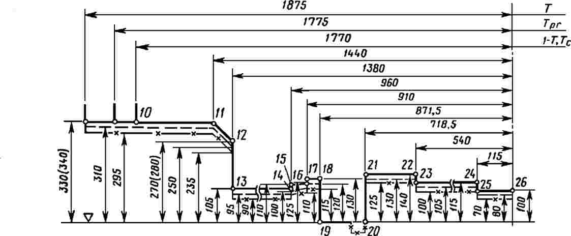
Note: For the rolling stock which is intend to be used on track of 1 520 mm, able to pass over marshalling humps and rail brakes.
Appendix C
Special provisions for on track machines (OTM)
C.1 Strength of vehicle structure
The requirements of the clause 4.2.2.4 of this TSI are complemented as follow:
The machine frame shall be able to withstand either the static loads of the specification referenced in Annex J-1, index 7 or the static loads according to the specification referenced in Annex J-1, index 102 without exceeding the permissible values given there in.
The corresponding structural category of the specification referenced in Annex J-1, index 102 is as follows:
|
— |
for machines not permitted to be loose shunted or hump shunted: F-II; |
|
— |
for all other machines: F-I. |
The acceleration in x-direction according to the specification referenced in Annex J-1, index 7, Table 13 or to the specification referenced in Annex J-1, index 102, Table 10 shall be ± 3 g.
C.2 Lifting and jacking
The machine body shall incorporate lifting points by which the whole machine is capable of being safely lifted or jacked. The location of the lifting and jacking points shall be defined.
To facilitate the work during repair or inspection or when on-tracking the machines, the machines shall be provided on both long sides with at least two lifting points, at which the machines can be lifted in empty or loaded condition.
To allow positioning of jacking devices, clearances shall be provided under the lifting points which shall not be blocked by the presence of non-removable parts. The load cases shall be consistent with the ones chosen in Appendix C.1 of this TSI and shall apply for lifting and jacking under workshop and servicing operations.
C.3 Running dynamic behaviour
The running characteristics are permitted to be determined by running tests or by reference to a similar type approved machine as detailed in clause 4.2.3.4.2 of this TSI or by simulation.
The following additional deviations from the specification referenced in Annex J-1, index 16 apply:
|
— |
The test shall always be taken as the simplified method for this type of machines |
|
— |
when running tests according to the specification referenced in Annex J-1, index 16 are done with wheel profile in new condition, these are valid for a maximum distance of 50 000 km. After 50 000 km it is necessary to:
|
|
— |
in general, stationary tests to determine the parameters of characteristic running gear in accordance with to the specification referenced in Annex J-1, index 16, clause 5.4.3.2 are not necessary; |
|
— |
if the required test speed cannot be obtained by the machine itself, the machine shall be hauled for the tests. |
|
— |
when test zone 3 (as described in Table 9 of to the specification referenced in Annex J-1, index 16) is used it is sufficient to have a minimum of 25 conformant track sections. |
Running behaviour can be proven by simulation of the tests described in to the specification referenced in Annex J-1, index 16 (with the exceptions as specified above) when there is a validated model of representative track and operating conditions of the machine.
A model of a machine for simulation of running characteristics shall be validated by comparing the model results against the results of running tests when the same input of track characteristic is used.
A validated model is a simulation model that has been verified by an actual running test that excites the suspension sufficiently and where there is a close correlation between the results of the running test and the predictions from the simulation model over the same test track.
Appendix D
On-board energy measurement system
1. Requirements for on-board energy measuring system (EMS) — System requirements
The functions of the system shall be:
|
— |
Energy measurement function (EMF), measuring the voltage and current, calculating the energy and producing energy data. |
|
— |
Data handling system (DHS), producing compiled energy billing data sets for energy billing purposes, by merging data from the EMF with time data and geographical position, and storing it to be sent to on-ground data collection system (DCS) by a communication system. |
|
— |
On-board location function, giving geographical position of the traction unit. |
Where data coming from the on-board location function is not necessary for billing purposes in the Member State concerned, it is permissible to not install the components dedicated to that function. In any case, any such EMS system shall be produced with consideration of the possible future inclusion of a location function.
The functions above may be performed by individual devices or may be combined in one or more integrated assemblies.
The abovementioned functions and their data flow diagram are illustrated in the figure below.
Figure D-1

The EMS shall measure energy supplied by the power supply systems for which the traction unit is designed and shall fulfil the following requirements:
|
— |
all active and reactive energy taken from and returned to the OCL is measured; |
|
— |
the EMS rated current and voltage shall be matched to the traction unit rated current and voltage; |
|
— |
it shall continue to function correctly when changing between traction energy supply systems; |
|
— |
the EMS shall be protected from non-authorised access; |
|
— |
loss of the power supply to the EMS shall not affect data stored in the EMS. |
It is permissible to access the data in the EMS for other purposes (e.g. feedback to the driver in connection with the efficient operation of the train) provided that it can be demonstrated that the integrity of EMS functions and data are not compromised by this arrangement.
2. Energy measuring function (EMF)
2.1. Metrological requirements
EMF is subject to metrological control, which shall be executed in accordance with the following:
|
(1) |
Accuracy of EMF for active energy measurement shall comply with clauses 4.2.4.1 to 4.2.4.4 of the specification referenced in Annex J-1, index 103 |
|
(2) |
Each device containing one or more functions of EMF shall indicate:
|
The accuracy class shall be verified by testing.
2.2. Other requirements
The measured energy values produced by EMF shall have a time reference period of 5 minutes defined by the UTC clock time at the end of each time reference period; originating from the time stamp 00:00:00.
It is permitted to use a shorter measuring period if the data can be aggregated on-board into 5 minutes time reference period.
3. Data handling system (DHS)
The DHS shall compile the data without corrupting them.
The DHS shall use, as a time reference, the same source of clock as in the EMF.
The DHS shall incorporate data storage with a memory capacity sufficient to store the compiled data of at least 60 days' continuous work.
The DHS shall have a capability to be interrogated locally by authorised personnel on board the train using appropriate equipment (e.g. laptop computer) in order to provide an opportunity for audit, and an alternative method of recovering data.
The DHS shall produce CEBD (compiled energy billing data sets) by merging the following data for each time reference period:
|
— |
unique EMS identification number, consisting of the European vehicle number (EVN) followed by one additional digit uniquely identifying each EMS on-board the traction unit, and no dividers included; |
|
— |
end time of each period, defined as year, month, day, hour, minute and second; |
|
— |
the location data at the end of each period; |
|
— |
consumed/regenerated active and reactive (if appropriate) energy in each period, in units of Wh (active energy) and varh (reactive energy) or their decimal-multiples. |
4. Location function
The location function shall provide location data to the DHS which originates from an external source.
The data from the location function shall be synchronised in accordance with UTC clock time and time reference period with the on-board EMF.
The location function shall provide the position expressed in latitude and longitude using decimal degrees with five decimal places. Positive values shall be used for North and East; negative values shall be used for South and West.
In open air the location function shall have an accuracy of 250 m or less.
5. On-board to ground communication
The specification related to interface protocols and transferred data format are an open point.
6. Particular assessment procedures
6.1. Energy measurement system
Where assessment methods set out in the standard series referenced in Annex J-1, index 103, 104 and 105 are referenced below, only those aspects necessary for the assessment of the requirements above in this Appendix D shall be undertaken in relation to the EMS which is a part of the EC verification activity for the rolling stock subsystem
6.1.1.
The accuracy of the each device containing one or more functions of EMF shall be assessed by testing each function, under reference conditions, using the relevant method as described in clause 5.4.3.4.1, 5.4.3.4.2 and 5.4.4.3.1 of the specification referenced in Annex J-1, index 103. The input quantity and power factor range when testing shall correspond to the values set out in Table 3 of the specification referenced in Annex J-1, index 103.
The accuracy of the complete EMF shall be assessed by calculation, using the method described in clause 4.2.4.2 of the specification referenced in Annex J-1, index 103.
The effects of temperature on accuracy of the each device containing one or more functions of EMF shall be assessed by testing each function, under reference conditions (except for temperature), using the relevant method as described in clause 5.4.3.4.3.1, and 5.4.4.3.2.1 of the specification referenced in Annex J-1, index 103.
The mean temperature coefficient of each device containing one or more functions of EMF shall be assessed by testing each function, under reference conditions (except for temperature), using the relevant method as described in clause 5.4.3.4.3.2 and 5.4.4.3.2.2 of the specification referenced in Annex J-1, index 103.
6.1.2
The compiling and handling of data within the DHS shall be assessed by testing using the method as described in clause 5.4.8.3.1, 5.4.8.5.1, 5.4.8.5.2 and 5.4.8.6 of the specification referenced in Annex J-1, index 104.
6.1.3
The correct functioning of the EMS shall be assessed by testing using the method as described in clause 5.3.2.2, 5.3.2.3, 5.3.2.4 and 5.5.3.2 of the specification referenced in Annex J-1, index 105.
Appendix E
Anthropometric measurements of the driver
The following data represents the ‘state of the art’ and shall be used.
Note: they will be subject of an EN standard currently under drafting process.
|
— |
Principal anthropometric measurements of the shortest and tallest driving staff: The dimensions given in Appendix E of the UIC 651 (4th edition, July 2002) shall be taken into consideration. |
|
— |
Additional anthropometric dimensions of the shortest and tallest driving staff: The dimensions given in Appendix G of the UIC 651 (4th edition, July 2002) shall be taken into consideration. |
Appendix F
Front visibility
The following data represents the ‘state of the art’ and shall be used.
Note: they will be subject of an EN standard currently under drafting process.
F.1. General
The design of the cab shall support the drivers' view of all external information that form part of the driving task as well as protecting the driver from external sources of visual interference. This shall include the following:
|
— |
Flicker at the lower edge of the windscreen, which can cause fatigue, shall be reduced |
|
— |
Protection shall be provided from the sun and glare of headlights from oncoming trains, without reducing the drivers' view of external signs, signals and other visual information |
|
— |
Location of cab equipment shall not block or distort the drivers view of external information |
|
— |
The dimension, location, shape and finishes (including maintenance) of the windows shall not inhibit the drivers external view and shall support the driving task |
|
— |
The location, type and quality of windscreen cleaning and clearance devices shall ensure that the driver is able to maintain a clear external view in most weather and operating conditions, and shall not inhibit the drivers external view. |
|
— |
The driver's cab shall be designed in such a way that the driver is facing forwards when driving. |
|
— |
The driver's cab shall be designed to allow the driver at his seated driving position a clear and unobstructed line of sight in order to distinguish fixed signals set to both the left and right of the track, as defined in Appendix D of the UIC 651(4th edition, July 2002). |
Note: the position of the seat in the Appendix D mentionned here above has to be considered as an example; the TSI does not impose the position of the seat (left, central or right) in the cab; the TSI does not impose the standing driving position on all types of units.
The rules expressed in the Appendix above govern the conditions of visibility for each running direction along straight track and in curves with a radius of 300 m and more. They apply to the position(s) of the driver.
Notes:
|
— |
in case of cab fitted with 2 driver's seats (option with 2 driving positions), they apply to the 2 seated positions. |
|
— |
for locomotives with central cab and for OTMs, the clause 4.2.9.1.3.1 of the TSI specify particular conditions. |
F.2. Reference position of vehicle in relation to track:
The clause 3.2.1 of the UIC 651(4th edition, July 2002) shall apply.
The supplies and payload shall be considered as defined in the specification referenced in Annex J-1, index 13 and clause 4.2.2.10 of this TSI.
F.3. Reference position for the eyes of crew members
The clause 3.2.2 of the UIC 651(4th edition, July 2002) shall apply.
The distance from the driver's eyes in seating posture to the windscreen shall be higher than or equal to 500 mm.
F.4. Conditions of visibility
The clause 3.3 of the UIC 651(4th edition, July 2002) shall apply.
Note: the clause 3.3.1 of the UIC 651 refers for the standing position to its clause 2.7.2, specifying a minimum distance of 1.8 meters between floor and top edge of the front window.
Appendix G
Servicing
Connections for the toilet discharge system on rolling stock:
Figure G1
Evacuation nozzle (Inner part)

General tolerances +/– 0,1
Material: stainless steel
Figure G2
Optional flushing connection for the toilet tank (Inner part)

General tolerances +/– 0,1
Material: stainless steel
Appendix H
Assessment of the rolling stock subsystem
H.1 Scope
This Appendix indicates the assessment of conformity of the rolling stock subsystem.
H.2 Characteristics and modules
The sub-system characteristics to be assessed in the different phases of design, development and production are marked by X in Table H.1. A cross in column 4 of Table H.1 indicates that the relevant characteristics shall be verified by testing each single subsystem.
Table H.1
Assessment of the rolling stock subsystem
|
1 |
2 |
3 |
4 |
5 |
|
|
Characteristics to be assessed, as specified in clause 4.2 of this TSI |
Design and development phase |
Production phase |
Particular assessment procedure |
||
|
Design review |
Type Test |
Routine Test |
|||
|
Element of the Rolling Stock sub-system |
Clause |
|
|
|
Clause |
|
Structure and mechanical parts |
4.2.2 |
|
|||
|
Inner coupling |
4.2.2.2.2 |
X |
n.a. |
n.a. |
— |
|
End coupling |
4.2.2.2.3 |
X |
n.a. |
n.a. |
— |
|
IC automatic centre buffer coupler |
5.3.1 |
X |
X |
X |
— |
|
IC manual end coupling |
5.3.2 |
X |
X |
X |
— |
|
Rescue coupling |
4.2.2.2.4 |
X |
X |
n.a. |
— |
|
IC rescue coupling |
5.3.3 |
X |
X |
X |
|
|
Staff access for coupling and uncoupling |
4.2.2.2.5 |
X |
X |
n.a. |
— |
|
Gangways |
4.2.2.3 |
X |
X |
n.a. |
— |
|
Strength of vehicle structure |
4.2.2.4 |
X |
X |
n.a. |
— |
|
Passive safety |
4.2.2.5 |
X |
X |
n.a. |
— |
|
Lifting and jacking |
4.2.2.6 |
X |
X |
n.a. |
— |
|
Fixing of devices to carbody structure |
4.2.2.7 |
X |
n.a. |
n.a. |
— |
|
Staff and freight access doors |
4.2.2.8 |
X |
X |
n.a. |
— |
|
Mechanical characteristics of glass |
4.2.2.9 |
X |
n.a. |
n.a. |
— |
|
Load conditions and weighted mass |
4.2.2.10 |
X |
X |
X |
6.2.3.1 |
|
Track interaction and gauging |
4.2.3 |
|
|||
|
Gauging |
4.2.3.1 |
X |
n.a. |
n.a. |
— |
|
Wheel load |
4.2.3.2.2 |
X |
X |
n.a |
6.2.3.2 |
|
Rolling Stock characteristics for compatibility with train detection systems |
4.2.3.3.1 |
X |
X |
X |
— |
|
Axle bearing condition monitoring |
4.2.3.3.2 |
X |
X |
n.a. |
— |
|
Safety against derailment running on twisted track |
4.2.3.4.1 |
X |
X |
n.a. |
6.2.3.3 |
|
Running dynamic behaviour requirements |
4.2.3.4.2 (a) |
X |
X |
n.a. |
6.2.3.4 |
|
Active systems — safety requirement |
4.2.3.4.2 (b) |
X |
n.a. |
n.a. |
6.2.3.5 |
|
Limit values for running safety |
4.2.3.4.2.1 |
X |
X |
n.a. |
6.2.3.4 |
|
Track loading limit values |
4.2.3.4.2.2 |
X |
X |
n.a. |
6.2.3.4 |
|
Equivalent conicity |
4.2.3.4.3 |
X |
n.a. |
n.a. |
— |
|
Design values for new wheel profiles |
4.2.3.4.3.1 |
X |
n.a. |
n.a. |
6.2.3.6 |
|
In-service values of wheelset equivalent conicity |
4.2.3.4.3.2 |
X |
|
|
— |
|
Structural design of bogie frame |
4.2.3.5.1 |
X |
X. |
n.a. |
— |
|
Mechanical and geometrical characteristics of wheelsets |
4.2.3.5.2.1 |
X |
X |
X |
6.2.3.7 |
|
Mechanical and geometrical characteristics of wheels |
4.2.3.5.2.2 |
X |
X |
X |
— |
|
Wheels (IC) |
5.3.2 |
X |
X |
X |
6.1.3.1 |
|
Variable gauge wheelsets |
4.2.3.5.2.3 |
open |
open |
open |
Open |
|
Minimum curve radius |
4.2.3.6 |
X |
n.a. |
n.a. |
— |
|
Life guards |
4.2.3.7 |
X |
n.a. |
n.a. |
— |
|
Braking |
4.2.4 |
|
|||
|
Functional requirements |
4.2.4.2.1 |
X |
X |
n.a |
— |
|
Safety requirements |
4.2.4.2.2 |
X |
n.a |
n.a |
6.2.3.5 |
|
Type of brake system |
4.2.4.3 |
X |
X |
n.a |
— |
|
Brake command |
4.2.4.4 |
|
|||
|
Emergency braking |
4.2.4.4.1 |
X |
X |
X |
— |
|
Service braking |
4.2.4.4.2 |
X |
X |
X |
— |
|
Direct braking command |
4.2.4.4.3 |
X |
X |
X |
— |
|
Dynamic braking command |
4.2.4.4.4 |
X |
X |
n.a |
— |
|
Parking braking command |
4.2.4.4.5 |
X |
X |
X |
— |
|
Braking performance |
4.2.4.5 |
|
|||
|
General requirements |
4.2.4.5.1 |
X |
n.a |
n.a |
— |
|
Emergency braking |
4.2.4.5.2 |
X |
X |
X |
6.2.3.8 |
|
Service braking |
4.2.4.5.3 |
X |
X |
X |
6.2.3.9 |
|
Calculations related to thermal capacity |
4.2.4.5.4 |
X |
n.a |
n.a |
— |
|
Parking brake |
4.2.4.5.5 |
X |
n.a |
n.a |
— |
|
Limit of wheel rail adhesion profile |
4.2.4.6.1 |
X |
n.a |
n.a |
— |
|
Wheel slide protection system |
4.2.4.6.2 |
X |
X |
n.a |
6.2.3.10 |
|
Wheel slide protection system (IC) |
5.3.3 |
X |
X |
X |
6.1.3.2 |
|
Interface with traction — Braking systems linked to traction (electric, hydro-dynamic) |
4.2.4.7 |
X |
X |
X |
— |
|
Braking system independent of adhesion conditions |
4.2.4.8 |
|
|||
|
General |
4.2.4.8.1. |
X |
n.a |
n.a |
— |
|
Magnetic track brake |
4.2.4.8.2. |
X |
X |
n.a |
— |
|
Eddy current track brake |
4.2.4.8.3 |
open |
Open |
Open |
Open |
|
Brake state and fault indication |
4.2.4.9 |
X |
X |
X |
— |
|
Brake requirements for rescue purposes |
4.2.4.10 |
X |
X |
n.a |
— |
|
Passenger related items |
4.2.5 |
|
|||
|
Sanitary systems |
4.2.5.1 |
X |
n.a |
n.a |
6.2.3.11 |
|
Public address system: audible communication system |
4.2.5.2 |
X |
X |
X |
— |
|
Passenger alarm |
4.2.5.3 |
X |
X |
X |
— |
|
Passenger alarm — safety requir. |
4.2.5.3 |
X |
n.a |
n.a |
6.2.3.5 |
|
Communication devices for passengers |
4.2.5.4 |
X |
X |
X |
— |
|
Exterior doors: access to and egress from Rolling Stock |
4.2.5.5 |
X |
X |
X |
— |
|
Exterior doors — safety requir. |
4.2.5.5 |
X |
n.a |
n.a |
6.2.3.5 |
|
Exterior door system construction |
4.2.5.6 |
X |
n.a |
n.a |
— |
|
inter-unit doors |
4.2.5.7 |
X |
X |
n.a |
— |
|
Internal air quality |
4.2.5.8 |
X |
n.a |
n.a |
6.2.3.12 |
|
Body side windows |
4.2.5.9 |
X |
|
|
— |
|
Environmental conditions and aerodynamic effects |
4.2.6 |
|
|||
|
Environmental conditions |
4.2.6.1 |
|
|||
|
Temperature |
4.2.6.1.1 |
X |
n.a. X (1) |
n.a. |
— |
|
Snow, ice and hail |
4.2.6.1.2 |
X |
n.a. X (1) |
n.a. |
— |
|
Aerodynamic effects |
4.2.6.2 |
|
|||
|
Slipstream effects on passengers on platform and on workers trackside |
4.2.6.2.1 |
X |
X |
n.a. |
6.2.3.13 |
|
Head pressure pulse |
4.2.6.2.2 |
X |
X |
n.a. |
6.2.3.14 |
|
Maximum pressure variations in tunnels |
4.2.6.2.3 |
X |
X |
n.a. |
6.2.3.15 |
|
Cross wind |
4.2.6.2.4 |
X |
n.a |
n.a. |
6.2.3.16 |
|
External lights & visible and audible warning devices |
4.2.7 |
|
|||
|
External front and rear lights |
4.2.7.1 |
|
|||
|
Head lights IC |
4.2.7.1.1 5.3.6 |
X |
X |
n.a |
— 6.1.3.3 |
|
Marker lights IC |
4.2.7.1.2 5.3.7 |
X |
X |
n.a |
— 6.1. 3.4 |
|
Tail lights IC |
4.2.7.1.3 5.3.8 |
X |
X |
n.a |
— 6.1.3.5 |
|
Lamp controls |
4.2.7.1.4 |
X |
X |
n.a |
— |
|
Horn |
4.2.7.2 |
|
|||
|
General — warning sound IC |
4.2.7.2.1 5.3.9 |
X |
X |
n.a |
— 6.1.3.6 |
|
Warning horn sound pressure levels |
4.2.7.2.2 5.3.9 |
X |
X |
n.a |
6.2.3.17 6.1.3.6 |
|
Protection |
4.2.7.2.3 |
X |
n.a |
n.a |
— |
|
Control |
4.2.7.2.4 |
X |
X |
n.a |
— |
|
Traction and electrical equipment |
4.2.8 |
|
|||
|
Traction performance |
4.2.8.1 |
|
|||
|
General |
4.2.8.1.1 |
|
|||
|
Requirements on performance |
4.2.8.1.2 |
X |
n.a |
n.a |
— |
|
Power supply |
4.2.8.2 |
|
|||
|
General |
4.2.8.2.1 |
X |
n.a |
n.a |
— |
|
Operation within range of voltages and frequencies |
4.2.8.2.2 |
X |
X |
n.a |
— |
|
Regenerative brake with energy to the overhead contact line |
4.2.8.2.3 |
X |
X |
n.a |
— |
|
Maximum power and current from the overhead contact line |
4.2.8.2.4 |
X |
X |
n.a |
6.2.3.18 |
|
Maximum current at standstill for DC systems |
4.2.8.2.5 |
X |
X |
n.a |
— |
|
Power factor |
4.2.8.2.6 |
X |
X |
n.a |
6.2.3.19 |
|
System energy disturbances |
4.2.8.2.7 |
X |
X |
n.a |
— |
|
Energy consumption measuring function |
4.2.8.2.8 |
X |
X |
n.a |
— |
|
Requirements linked to pantograph |
4.2.8.2.9 |
X |
X |
n.a |
6.2.3.20 & 21 |
|
Pantograph (IC) |
5.3.10 |
X |
X |
X |
6.1.3.7 |
|
Contact strips (IC) |
5.3.11 |
X |
X |
X |
6.1.3.8 |
|
Electrical protection of the train IC Main circuit breaker |
4.2.8.2.10 5.3.12 |
X |
X |
n.a |
— |
|
Diesel and other thermal traction system |
4.2.8.3 |
— |
— |
— |
Other Directive |
|
Protection against electrical hazards |
4.2.8.4 |
X |
X |
n.a |
— |
|
Cab and operation |
4.2.9 |
|
|||
|
Driver's Cab |
4.2.9.1 |
X |
n.a |
n.a |
— |
|
General |
4.2.9.1.1 |
X |
n.a |
n.a |
— |
|
Access and egress |
4.2.9.1.2 |
X |
n.a |
n.a |
— |
|
Access and egress in operating conditions |
4.2.9.1.2.1 |
X |
n.a |
n.a |
— |
|
Driver's cab emergency exit |
4.2.9.1.2.2 |
X |
n.a |
n.a |
— |
|
External visibility |
4.2.9.1.3 |
X |
n.a |
n.a |
— |
|
Front visibility |
4.2.9.1.3.1 |
X |
n.a |
n.a |
— |
|
Rear and side view |
4.2.9.1.3.2 |
X |
n.a |
n.a |
— |
|
Interior layout |
4.2.9.1.4 |
X |
n.a |
n.a |
— |
|
Driver's seat IC |
4.2.9.1.5 5.3.13 |
X X |
n.a X |
n.a X |
— |
|
Driver's desk- Ergonomics |
4.2.9.1.6 |
X |
n.a |
n.a |
— |
|
Climate control and air quality |
4.2.9.1.7 |
X |
X |
n.a |
6.2.3.12 |
|
Internal lighting |
4.2.9.1.8 |
X |
X |
n.a |
— |
|
Windscreen-Mechanical characteristics |
4.2.9.2.1 |
X |
X |
n.a |
6.2.3.22 |
|
Windscreen-Optical characteristics |
4.2.9.2.2 |
X |
X |
n.a |
6.2.3.22 |
|
Windscreen-Equipment |
4.2.9.2.3 |
X |
X |
n.a |
— |
|
Driver machine interface |
4.2.9.3 |
|
|||
|
Driver's activity control function |
4.2.9.3.1 |
X |
X |
X |
— |
|
Speed indication |
4.2.9.3.2 |
— |
— |
— |
— |
|
Driver display unit and screens |
4.2.9.3.3 |
X |
X |
n.a |
— |
|
Controls and indicators |
4.2.9.3.4 |
X |
X |
n.a |
— |
|
Labelling |
4.2.9.3.5 |
X |
n.a |
n.a |
— |
|
Radio remote control function by staff for shubting operation |
4.2.9.3.6 |
X |
X |
n.a |
— |
|
Onboard tools and portable equipment |
4.2.9.4 |
X |
n.a |
n.a |
— |
|
Storage facility for staff personal effects |
4.2.9.5 |
X |
n.a |
n.a |
— |
|
Recording device |
4.2.9.6 |
X |
X |
X |
— |
|
Fire safety and evacuation |
4.2.10 |
|
|||
|
General and categorisation |
4.2.10.1 |
X |
n.a |
n.a |
— |
|
Mesures to prevent fire |
4.2.10.2 |
X |
X |
n.a |
— |
|
Mesures to detect/control fire |
4.2.10.3 |
X |
X |
n.a |
— |
|
Requirements related to emergencies |
4.2.10.4 |
X |
X |
n.a |
— |
|
Requirements related to evacuation |
4.2.10.5 |
X |
X |
n.a |
— |
|
Servicing |
4.2.11 |
|
|||
|
Cleaning of driver's cab windscreen |
4.2.11.2 |
X |
X |
n.a |
— |
|
Connection to toilet discharge system IC |
4.2.11.3 5.3.14 |
X |
n.a |
n.a |
— |
|
Water refilling equipment |
4.2.11.4 |
X |
n.a |
n.a |
— |
|
Interface for water refilling IC |
4.2.11.5 5.3.15 |
X |
n.a |
n.a |
— |
|
Special requirements for stabling of trains |
4.2.11.6 |
X |
X |
n.a |
— |
|
Refuelling equipment |
4.2.11.7 |
X |
n.a |
n.a |
— |
|
Train interior cleaning — power supply |
4.2.11.8 |
X |
n.a |
n.a |
— |
|
Documentation for operation and maintenance |
4.2.12 |
|
|||
|
General |
4.2.12.1 |
X |
n.a |
n.a |
— |
|
General documentation |
4.2.12.2 |
X |
n.a |
n.a |
— |
|
Documentation related to maintenance |
4.2.12.3 |
X |
n.a |
n.a |
— |
|
The maintenance design justification file |
4.2.12.3.1 |
X |
n.a |
n.a |
— |
|
The Maintenance description file |
4.2.12.3.2 |
X |
n.a |
n.a |
— |
|
Operating documentation |
4.2.12.4 |
X |
n.a |
n.a |
— |
|
Lifting diagram and instructions |
4.2.12.4 |
X |
n.a |
n.a |
— |
|
Rescue related descriptions |
4.2.12.5 |
X |
n.a |
n.a |
— |
(1) Type test if and as defined by the Applicant.
Appendix I
Aspects for which the technical specification is not available (open points)
Open points that relate to technical compatibility between the vehicle and the network:
|
Element of the Rolling Stock sub-system |
Clause of this TSI |
Technical aspect not covered by this TSI |
Comments |
|
Compatibility with train detection systems |
4.2.3.3.1 |
See specification referenced in Annex J-2, index 1. |
Open points also identified in the TSI CCS. |
|
Running dynamic behaviour for 1 520 mm track gauge system |
4.2.3.4.2 4.2.3.4.3 |
Running dynamic behaviour. Equivalent conicity. |
Normative documents referred to in the TSI are based on experience gained on the 1 435 mm system. |
|
Braking system independent of adhesion conditions |
4.2.4.8.3 |
Eddy current track brake |
Equipment not mandatory. Compatibility with concerned network to be checked. |
|
Aerodynamic effects for 1 520 mm, 1 524 mm and 1 668 mm track gauge systems |
4.2.6.2 |
Limit values and conformity assessment |
Normative documents referred to in the TSI are based on experience gained on the 1 435 mm system. |
|
Aerodynamic effect on ballasted track for RST of design speed ≥ 190 km/h |
4.2.6.2.5 |
Limit value and conformity assessment in order to limit risks induced by the projection of ballast |
Ongoing work within CEN. Open point also in TSI INF. |
Open points that do not relate to technical compatibility between the vehicle and the network:
|
Element of the Rolling Stock sub-system |
Clause of this TSI |
Technical aspect not covered by this TSI |
Comments |
|
Passive Safety |
4.2.2.5 |
Application of scenarios 1 and 2 to locomotives with centre couplers and traction effort higher than 300 kN. |
If no technical solution available, possible restrictions at the level of operation. |
|
Variable gauge wheelsets |
4.2.3.5.2.3 |
Conformity assessment |
Design option. |
|
On-board energy measurement system |
4.2.8.2.8 and Appendix D |
On-board to ground communication: specification related to interface protocols and transferred data format. |
Description of on-board to ground communication shall be provided in the technical documentation. The standard series EN 61375-2-6 should be used. |
|
Fire Containment and Control Systems |
4.2.10.3.4 |
Conformity assessment of FCCS other than full partitions. |
Assessment procedure of efficiency for controlling fire and smoke developed by CEN according to a request for standard issued by ERA. |
Appendix J
Technical specifications referred to in this TSI
J.1 Standards or normative documents
|
|
TSI |
Normative document |
||
|
Index No |
Characteristics to be assessed |
Point |
Document No |
Mandatory points |
|
1 |
Inner coupling for articulated units |
4.2.2.2.2 |
EN 12663-1:2010 |
6.5.3, 6.7.5 |
|
2 |
End coupling — manual UIC type — pipes interface |
4.2.2.2.3 |
EN 15807:2012 |
relevant cl. (1) |
|
3 |
End coupling — manual UIC type — end cocks |
4.2.2.2.3 |
EN 14601:2005 +A1:2010 |
relevant cl. (1) |
|
4 |
End coupling — manual UIC type — lateral location of brake pipe and cocks |
4.2.2.2.3 |
UIC 648:Sept 2001 |
relevant cl. (1) |
|
5 |
Rescue coupling — interface with recovery unit |
4.2.2.2.4 |
UIC 648:Sept 2001 |
relevant cl. (1) |
|
6 |
Staff access for coupling and uncoupling — space for shunting staff |
4.2.2.2.5 |
EN 16116-1:2013 |
6.2 |
|
7 |
Strength of vehicle structure — general categorisation of rolling stock method of verification |
4.2.2.4 Appendix C C |
EN 12663-1:2010 |
relevant cl. (1) 5.2 9.2 6.1 – 6.5 |
|
8 |
Passive safety — general categorisation scenarios obstacle deflector |
4.2.2.5 |
EN 15227:2008 +A1:2011 |
Except Annex A 4–table 1 5–table 2, 6 5-table 3, 6.5 |
|
9 |
Lifting and jacking — geometry of permanent and removable points |
4.2.2.6 |
EN 16404:2014 |
5.3, 5.4 |
|
10 |
Lifting and jacking — marking |
4.2.2.6 |
EN 15877-2:2013 |
4.5.17 |
|
11 |
Lifting and jacking — strength method of verification |
4.2.2.6 |
EN 12663-1:2010 |
6.3.2, 6.3.3, 9.2 |
|
12 |
Fixing of devices to carbody structure |
4.2.2.7 |
EN 12663-1:2010 |
6.5.2 |
|
13 |
Load conditions and weighed mass — load conditions hypothesis of load conditions |
4.2.2.10 |
EN 15663:2009 /AC:2010 |
2.1 relevant cl. (1) |
|
14 |
Gauging — method, reference contours verification of pantograph gauge |
4.2.3.1 |
EN 15273-2:2013 |
relevant cl. (1) A.3.12 |
|
15 |
Axle bearing condition monitoring — zone visible to track side equipment |
4.2.3.3.2.2 |
EN 15437-1:2009 |
5.1, 5.2 |
|
16 |
Running dynamic behaviour |
4.2.3.4.2 Appendix C |
EN 14363:2005 |
relevant cl. (1) |
|
17 |
Running dynamic behaviour — limit values for running safety |
4.2.3.4.2.1 |
EN 14363:2005 |
5.3.2.2 |
|
18 |
Running dynamic behaviour — for rolling stock with a cant deficiency > 165 mm |
4.2.3.4.2.1 |
EN 15686:2010 |
relevant cl. (1) |
|
19 |
Running dynamic behaviour — track loading limit values |
4.2.3.4.2.2 |
EN 14363:2005 |
5.3.2.3 |
|
20 |
Structural design of the bogie frame |
4.2.3.5.1 |
EN 13749:2011 |
6.2, Annex C |
|
21 |
Structural design of the bogie frame — body to bogie connection |
4.2.3.5.1 |
EN 12663-1:2010 |
relevant cl. (1) |
|
22 |
Braking — type of brake system, UIC brake system |
4.2.4.3 |
EN 14198:2004 |
5.4 |
|
23 |
Braking performance — calculation — general |
4.2.4.5.1 |
EN 14531-1:2005 or EN 14531-6:2009 |
relevant cl. (1) |
|
24 |
Braking performance — friction coefficient |
4.2.4.5.1 |
EN 14531-1:2005 |
5.3.1.4 |
|
25 |
Emergency braking performance — response time/delay time brake weight percentage |
4.2.4.5.2 |
EN 14531-1:2005 |
5.3.3 5.12 |
|
26 |
Emergency braking performance — calculation |
4.2.4.5.2 |
EN 14531-1:2005 or EN 14531-6:2009 |
relevant cl. (1) |
|
27 |
Emergency braking performance — friction coefficient |
4.2.4.5.2 |
EN 14531-1:2005 |
5.3.1.4 |
|
28 |
Service braking performance — calculation |
4.2.4.5.3 |
EN 14531-1:2005 or EN 14531-6:2009 |
relevant cl. (1) |
|
29 |
Parking brake performance — calculation |
4.2.4.5.5 |
EN 14531-1:2005 or EN 14531-6:2009 |
relevant cl. (1) |
|
30 |
Wheel slide protection system — design verification method wheel rotation monitoring system |
4.2.4.6.2 |
EN 15595:2009 |
4 5, 6 4.2.4.3 |
|
31 |
Magnetic track brake |
4.2.4.8.2 |
UIC 541-06:Jan 1992 |
Appendix 3 |
|
32 |
Door obstacle detection — sensitivity maximum force |
4.2.5.5.3 |
FprEN 14752:2014 |
5.2.1.4.1 5.2.1.4.2.2 |
|
33 |
Door emergency opening — manual force to open the door |
4.2.5.5.9 |
FprEN 14752:2014 |
5.5.1.5 |
|
34 |
Environmental conditions — temperature |
4.2.6.1.1 |
EN 50125-1:2014 |
4.3 |
|
35 |
Environmental conditions — snow, ice and hail conditions |
4.2.6.1.2 |
EN 50125-1:2014 |
4.7 |
|
36 |
Environmental conditions — obstacle deflector |
4.2.6.1.2 |
EN 15227:2008 +A1:2011 |
relevant cl. (1) |
|
37 |
Aerodynamic effects — crosswind method of verification |
4.2.6.2.4. |
EN 14067-6:2010 |
5 |
|
38 |
Head lights — colour dimmed headlamp luminous intensity full-beam headlamp luminous intensity alignment |
4.2.7.1.1 |
EN 15153-1:2013 |
5.3.3 5.3.4 Table 2 first line 5.3.4 Table 2 first line 5.3.5 |
|
39 |
Marker lights — colour spectral radiation distribution luminous intensity |
4.2.7.1.2 |
EN 15153-1:2013 |
5.4.3.1 Table 4 5.4.3.2 5.4.4 Table 6 |
|
40 |
Tail lights — colour luminous intensity |
4.2.7.1.3 |
EN 15153-1:2013 |
5.5.3 Table 7 5.5.4 Table 8 |
|
41 |
Warning horn sound pressure levels |
4.2.7.2.2 |
EN 15153-2:2013 |
5.2.2 |
|
42 |
Regenerative brake with energy to the overhead contac tline |
4.2.8.2.3 |
EN 50388:2012 |
12.1.1 |
|
43 |
Maximum power and current from the overhead contact line — automatic regulation of current |
4.2.8.2.4 |
EN 50388:2012 |
7.2 |
|
44 |
Power factor — verification method |
4.2.8.2.6 |
EN 50388:2012 |
6 |
|
45 |
System energy disturbances for AC systems — harmonics and dynamic effects compatibility study |
4.2.8.2.7 |
EN 50388:2012 |
10.1 10.3 Table 5 Annex D 10.4 |
|
46 |
Working range in height of pantograph (IC level) — characteristics |
4.2.8.2.9.1.2 |
EN 50206-1:2010 |
4.2, 6.2.3 |
|
47 |
Pantograph head geometry |
4.2.8.2.9.2 |
EN 50367:2012 |
5.3.2.2 |
|
48 |
Pantograph head geometry — type 1600 mm |
4.2.8.2.9.2.1 |
EN 50367:2012 |
Annex A.2 Figure A.6 |
|
49 |
Pantograph head geometry — type 1950 mm |
4.2.8.2.9.2.2 |
EN 50367:2012 |
Annex A.2 Figure A.7 |
|
50 |
Pantograph current capacity (IC level) |
4.2.8.2.9.3 |
EN 50206-1:2010 |
6.13.2 |
|
51 |
Pantograph lowering (RST level) — time to lower the pantograph ADD |
4.2.8.2.9.10 |
EN 50206-1:2010 |
4.7 4.8 |
|
52 |
Pantograph lowering (RST level) — dynamic insulating distance |
4.2.8.2.9.10 |
EN 50119:2009 |
Table 2 |
|
53 |
Electrical protection of the train — coordination of protection |
4.2.8.2.10 |
EN 50388:2012 |
11 |
|
54 |
Protection against electrical hazard |
4.2.8.4 |
EN 50153:2002 |
relevant cl. (1) |
|
55 |
Windscreen — mechanical characteristics |
4.2.9.2.1 |
EN 15152:2007 |
4.2.7, 4.2.9 |
|
56 |
Windscreen — primary/secondary images optical distorsion haze luminous transmittance chromaticity |
4.2.9.2.2 |
EN 15152:2007 |
4.2.2 4.2.3 4.2.4 4.2.5 4.2.6 |
|
57 |
Recording device — functional requirements recording performance integrity data integrity safeguard level of protection |
4.2.9.6 |
EN/IEC 62625-1:2013 |
4.2.1, 4.2.2, 4.2.3, 4.2.4 4.3.1.2.2 4.3.1. 4 4.3.1.5 4.3.1.7 |
|
58 |
Measures to prevent fire — material requirements |
4.2.10.2.1 |
EN 45545-2:2013 |
relevant cl. (1) |
|
59 |
Specific measures for flammable liquids |
4.2.10.2.2 |
EN 45545-2:2013 |
Table 5 |
|
60 |
Fire spreading protection measures for passenger rolling stock — partition test |
4.2.10.3.4 |
EN 1363-1:2012 |
relevant cl. (1) |
|
61 |
Fire spreading protection measures for passenger rolling stock — partition test |
4.2.10.3.5 |
EN 1363-1:2012 |
relevant cl. (1) |
|
62 |
Emergency lighting — lighting level |
4.2.10.4.1 |
EN 13272:2012 |
5.3 |
|
63 |
Running capability |
4.2.10.4.4 |
EN 50553:2012 |
relevant cl. (1) |
|
64 |
Interface for water filling |
4.2.11.5 |
EN 16362:2013 |
4.1.2 figure 1 |
|
65 |
Special requirements for stabling of trains — local extranla auxiliary power supply |
4.2.11.6 |
EN/IEC 60309-2:1999 |
relevant cl. (1) |
|
66 |
Automatic centre buffer coupler — type 10 |
5.3.1 |
EN 16019:2014 |
relevant cl. (1) |
|
67 |
Manual end coupling — UIC type |
5.3.2 |
EN 15551:2009 |
relevant cl. (1) |
|
68 |
Manual end coupling — UIC type |
5.3.2 |
EN 15566:2009 |
relevant cl. (1) |
|
69 |
Rescue coupler |
5.3.3 |
EN 15020:2006 +A1:2010 |
relevant cl. (1) |
|
70 |
Main circuit breaker — coordination of protection |
5.3.12 |
EN 50388:2012 |
11 |
|
71 |
Wheels — verification method decision criteria further verification method thermomechanical behaviour |
6.1.3.1 |
EN 13979-1:2003 +A2:2011 |
7.2.1, 7.2.2 7.2.3 7.3 6 |
|
72 |
Wheel slide protection — method of verification test programme |
6.1.3.2 |
EN 15595:2009 |
5 only 6.2.3 of 6.2 |
|
73 |
Head lamps — colour luminous intensity |
6.1.3.3 |
EN 15153-1:2013 |
6.3 6.4 |
|
74 |
Marker lamps — colour luminous intensity |
6.1.3.4 |
EN 15153-1:2013 |
6.3 6.4 |
|
75 |
Tail lamps — colour luminous intensity |
6.1.3.5 |
EN 15153-1:2013 |
6.3 6.4 |
|
76 |
Horn — sounding sound pressure level |
6.1.3.6 |
EN 15153-2:2013 |
6 6 |
|
77 |
Pantograph — static contact force |
6.1.3.7 |
EN 50367:2012 |
7.2 |
|
78 |
Pantograph — limit value |
6.1.3.7 |
EN 50119:2009 |
5.1.2 |
|
79 |
Pantograph — verification method |
6.1.3.7 |
EN 50206-1:2010 |
6.3.1 |
|
80 |
Pantograph — dynamic behaviour |
6.1.3.7 |
EN 50318:2002 |
relevant cl. (1) |
|
81 |
Pantograph — interaction characteristics |
6.1.3.7 |
EN 50317:2012 |
relevant cl. (1) |
|
82 |
Contact strips — verification method |
6.1.3.8 |
EN 50405:2006 |
5.2.2, 5.2.3, 5.2.4, 5.2.6, 5.2.7 |
|
83 |
Safety against derailment running on twisted track |
6.2.3.3 |
EN 14363:2005 |
4.1 |
|
84 |
Running dynamic behaviour — method of verification assessment of criteria conditions of assessment |
6.2.3.4 |
EN 14363:2005 |
5 relevant cl. (1) relevant cl. (1) |
|
85 |
Equivalent conicity — rail section definitions |
6.2.3.6 |
EN 13674-1:2011 |
relevant cl. (1) |
|
86 |
Equivalent conicity — wheel profile definitions |
6.2.3.6 |
EN 13715:2006 |
relevant cl. (1) |
|
87 |
Wheelset — assembly |
6.2.3.7 |
EN 13260:2009 +A1:2010 +A2:2012 |
3.2.1 |
|
88 |
Wheelset — axles, method of verification decision criteria |
6.2.3.7 |
EN 13103:2009 +A1:2010 +A2:2012 |
4, 5, 6 7 |
|
89 |
Wheelset — axles, method of verification decision criteria |
6.2.3.7 |
EN 13104:2009 +A1:2010 |
4, 5, 6 7 |
|
90 |
Axle boxes/bearings |
6.2.3.7 |
EN 12082:2007 |
6 |
|
91 |
Emergency braking performance |
6.2.3.8 |
EN 14531-1:2005 |
5.11.3 |
|
92 |
Service braking performance |
6.2.3.9 |
EN 14531-1:2005 |
5.11.3 |
|
93 |
Wheel slide protection, method of verification of performance |
6.2.3.10 |
EN 15595:2009 |
6.4 |
|
94 |
Slipstream effect — meteorological conditions, sensors, sensor accuracy, selection of valid data and processing of the data |
6.2.3.13 |
EN 14067-4:2005 +A1:2009 |
8.5.2 |
|
95 |
Head pressure pulse — method of verification CFD Moving model |
6.2.3.14 |
EN 14067-4:2005 +A1:2009 |
5.5.2 5.3 5.4.3 |
|
96 |
Maximum pressure variations — distance xp between the entrance portal and the measuring position, the definitions of ΔpFr, ΔpN, ΔpT, the minimum tunnel length |
6.2.3.15 |
EN 14067-5:2006 +A1:2010 |
relevant cl. (1) |
|
97 |
Horn — sound pressure level |
6.2.3.17 |
EN 15153-2:2013 |
5 |
|
98 |
Maximum power and current from the overhead contact line — method of verification |
6.2.3.18 |
EN 50388:2012 |
15.3 |
|
99 |
Power factor — method of verification |
6.2.3.19 |
EN 50388:2012 |
15.2 |
|
100 |
Current collection dynamic behaviour — dynamic tests |
6.2.3.20 |
EN 50317:2012 |
relevant cl. (1) |
|
101 |
Windscreen — characteristics |
6.2.3.22 |
EN 15152:2007 |
6.2.1 to 6.2.7 |
|
102 |
Structural strength |
Annex C.1 |
EN 12663-2:2010 |
5.2.1-5.2.4 |
|
103 |
On-board energy measurement system |
Annex D |
EN 50463-2:2012 |
relevant cl. (1) |
|
104 |
On-board energy measurement system |
Annex D |
EN 50463-3:2012 |
relevant cl. (1) |
|
105 |
On-board energy measurement system |
Annex D |
EN 50463-5:2012 |
relevant cl. (1) |
J.2 Technical documents (available on ERA website)
|
|
TSI |
ERA technical document |
||
|
Index No |
Characteristics to be assessed |
Point |
Mandatory ref Document No |
Points |
|
1 |
Interface between control-command signalling trackside and other subsytems |
4.2.3.3.1 |
ERA/ERTMS/033281 rev 2.0 |
3.1 & 3.2 |
|
2 |
Rolling stock dynamic behaviour |
4.2.3.4 |
ERA/TD/2012-17/INT rev 3.0 |
All |
(1) Clauses of the standard that are in direct relationship to the requirement expressed in the clause of the TSI indicated in column 3.
|
12.12.2014 |
EN |
Official Journal of the European Union |
L 356/394 |
COMMISSION REGULATION (EU) No 1303/2014
of 18 November 2014
concerning the technical specification for interoperability relating to ‘safety in railway tunnels’ of the rail system of the European Union
(Text with EEA relevance)
THE EUROPEAN COMMISSION,
Having regard to the Treaty on the Functioning of the European Union,
Having regard to Directive 2008/57/EC of the European Parliament and of the Council of 17 June 2008 on the interoperability of the rail system within the Community (1), and in particular Article 6(1), second subparagraph, thereof,
Whereas:
|
(1) |
Article 12 of Regulation (EC) No 881/2004 of the European Parliament and of the Council (2) requires the European Railway Agency (‘the Agency’) to ensure that the technical specifications for interoperability (the ‘TSIs’) are adapted to technical progress, market trends and social requirements and to propose to the Commission any amendments to the TSIs which it considers necessary. |
|
(2) |
By Decision C(2010)2576 of 29 April 2010, the Commission gave the Agency a mandate to develop and review the TSI's with a view to extending their scope to the whole rail system in the Union. Under the terms of that mandate, the Agency was requested to extend accordingly the scope of the TSI relating to ‘safety in railway tunnels’. |
|
(3) |
On 21 December 2012, the Agency issued a recommendation on the revised TSI relating to ‘safety in railway tunnels’. |
|
(4) |
In order to follow technological evolution and encourage modernisation, innovative solutions should be promoted and their implementation should, under certain conditions, be allowed. Where an innovative solution is proposed, the manufacturer or his authorised representative should state how they deviate from or how they complement to the relevant section of the TSI, and the innovative solution should be assessed by the Commission. If this assessment is positive, the Agency should define the appropriate functional and interface specifications of the innovative solution and develop the relevant assessment methods. |
|
(5) |
In accordance with Article 17(3) of Directive 2008/57/EC, Member States are to notify to the Commission and other Member States the technical rules, the conformity assessment and verification procedures to be used for specific cases, and the bodies responsible for carrying out these procedures. |
|
(6) |
Rolling stock currently operates under existing national, bilateral, multinational or international agreements. These agreements should not hinder current and future progress towards interoperability. The Member States should therefore notify such agreements to the Commission. |
|
(7) |
This Regulation should apply to tunnels irrespective of their traffic volume. |
|
(8) |
Some Member States already have safety rules in place which require a higher level of safety than that mandated in this TSI. This Regulation should allow Member States keeping such rules only concerning the infrastructure, energy and operation subsystems. Such existing rules are to be considered as national safety rules within the meaning of Article 8 of Directive 2004/49/EC of the European Parliament and of the Council (3). In addition, in accordance with Article 4 of this Directive, Member States shall ensure that railway safety is generally maintained and, where reasonably practicable, continuously improved, taking into consideration the development of Union legislation and technical and scientific progress and giving priority to the prevention of serious accidents. However, no additional measures should be prescribed for rolling stock. |
|
(9) |
Member States are competent to define the role and responsibility of the rescue services. For tunnels falling within the scope of application of this Regulation, Member States should arrange rescue access in coordination with the rescue services. It is important to specify measures in the field of rescue which are based on the assumption that rescue services intervening in a tunnel accident shall protect lives, not material values such as vehicles or structures. |
|
(10) |
Commission Decision 2008/163/EC (4) concerning a TSI relating to ‘safety in railway tunnels’ should hereby be repealed. |
|
(11) |
In order to prevent unnecessary additional costs and administrative burden, Decision 2008/163/EC should continue to apply after its repeal to the subsystems and projects referred to in Article 9(1)(a) of Directive 2008/57/EC. |
|
(12) |
The measures provided for in this Regulation are consistent with the opinion of the Committee established in accordance with Article 29(1) of Directive 2008/57/EC, |
HAS ADOPTED THIS REGULATION:
Article 1
The technical specification for interoperability (TSI) relating to the ‘safety in railway tunnels’ of the rail system of the entire European Union, as set out in the Annex, is hereby adopted.
Article 2
The TSI shall apply to the control-command and signalling, infrastructure, energy, operation, as well as rolling stock subsystems as described in Annex II to Directive 2008/57/EC.
The TSI shall apply to these subsystems in accordance with Section 7 of the Annex.
Article 3
The technical and geographical scope of this Regulation is set out in Sections 1.1 and 1.2 of the Annex.
Article 4
1. With regard to specific cases listed in Section 7.3 of the Annex to this Regulation, the conditions to be met for the verification of the interoperability pursuant to Article 17(2) of Directive 2008/57/EC shall be those laid down by national rules in force in the Member State which authorise the placing in service of the subsystems covered by this Regulation.
2. Within six months of the entry into force of this Regulation, each Member State shall notify the other Member States and the Commission of:
|
(a) |
the national rules referred to in paragraph 1; |
|
(b) |
the conformity assessment and verification procedures to be carried out to apply the national rules referred to in paragraph 1; |
|
(c) |
the bodies designated in accordance with Article 17(3) of Directive 2008/57/EC to carry out the conformity assessment and verification procedures with respect to the specific cases set out in Section 7.3 of the Annex. |
Article 5
1. Member States shall notify to the Commission the following types of agreement within six months of the entry into force of this Regulation:
|
(a) |
national agreements between the Member States and railway undertakings or infrastructure managers, agreed on either a permanent or a temporary basis and required by the very specific or local nature of the intended transport service; |
|
(b) |
bilateral or multilateral agreements between railway undertakings, infrastructure managers or safety authorities which deliver significant levels of local or regional interoperability; |
|
(c) |
international agreements between one or more Member States and at least one third country, or between railway undertakings or infrastructure managers of Member States and at least one railway undertaking or infrastructure manager of a third country, which deliver significant levels of local or regional interoperability. |
2. The agreements which have already been notified under Commission Decision 2006/920/EC (5), 2008/231/EC (6), 2011/314/EU (7) or 2012/757/EU (8) shall not be notified again.
3. Member States shall forthwith notify to the Commission any future agreements or modifications of the existing and already notified agreements.
Article 6
In accordance with Article 9(3) of Directive 2008/57/EC, each Member State shall communicate to the Commission within one year of the entry into force of this Regulation the list of projects being implemented within its territory and that are at an advanced stage of development.
Article 7
Each Member State, acting in accordance with Chapter 7 of the Annex to this Regulation, shall update the national implementation plans for the TSI, established in accordance with Article 4 of Decision 2006/920/EC, Article 4 of Decision 2008/231/EC and Article 5 of Decision 2011/314/EU.
Each Member State shall forward its updated implementation plan to the other Member States and the Commission by 1 July 2015 at the latest.
Article 8
1. In order to keep pace with technological progress, innovative solutions may be required which do not comply with the specifications set out in the Annex and/or for which the assessment methods set out in the Annex cannot be applied. In that case, new specifications and/or new assessment methods associated with those innovative solutions may be developed according to the provisions of paragraphs 2 to 5.
2. Innovative solutions may be related to the subsystems referred to in Article 2, their parts and their interoperability constituents.
3. If an innovative solution is proposed, the manufacturer or his authorised representative established within the Union shall declare how it deviates from or complements to the provisions of the relevant TSIs and shall submit the deviations to the Commission for analysis. The Commission may request the opinion of the Agency on the proposed innovative solution.
4. The Commission shall deliver an opinion on the innovative solution proposed. If this opinion is positive, the appropriate functional and interface specifications and the assessment method, which need to be included in the relevant TSIs in order to allow the use of this innovative solution, shall be developed and subsequently integrated into the relevant TSIs during the revision process pursuant to Article 6 of Directive 2008/57/EC. If the opinion is negative, the innovative solution proposed cannot be applied.
5. Pending the review of the relevant TSIs, a positive opinion delivered by the Commission shall be considered as an acceptable means of compliance with the essential requirements of Directive 2008/57/EC and may be used for the assessment of the subsystem.
Article 9
Decision 2008/163/EC is repealed with effect from 1 January 2015.
It shall however continue to apply to:
|
(a) |
subsystems authorised in accordance with that Decision; |
|
(b) |
projects for new, renewed or upgraded subsystems which, at the time of publication of this Regulation, are at an advanced stage of development or are the subject of a contract which is being carried out. |
Article 10
This Regulation shall enter into force on the twentieth day following that of its publication in the Official Journal of the European Union.
It shall apply from 1 January 2015.
This Regulation shall be binding in its entirety and directly applicable in all Member States.
Done at Brussels, 18 November 2014.
For the Commission
The President
Jean-Claude JUNCKER
(1) OJ L 191, 18.7.2008, p. 1.
(2) Regulation (EC) No 881/2004 of the European Parliament and of the Council of 29 April 2004 establishing a European Railway Agency (Agency Regulation) (OJ L 164, 30.4.2004, p. 1).
(3) Directive 2004/49/EC of the European Parliament and of the Council of 29 April 2004 on safety on the Community's railways and amending Council Directive 95/18/EC on the licensing of railway undertakings and Directive 2001/14/EC on the allocation of railway infrastructure capacity and the levying of charges for the use of railway infrastructure and safety certification (OJ L 164, 30.4.2004, p. 44).
(4) Commission Decision 2008/163/EC of 20 December 2007 concerning the technical specification of interoperability relating to ‘safety in railway tunnels’ in the trans-European conventional and high-speed rail system (OJ L 64, 7.3.2008, p. 1).
(5) Commission Decision 2006/920/EC of 11 August 2006 concerning the technical specification of interoperability relating to the subsystem Traffic Operation and Management of the trans-European conventional rail system (OJ L 359, 18.12.2006, p. 1).
(6) Commission Decision 2008/231/EC of 1 February 2008 concerning the technical specification of interoperability relating to the operation subsystem of the trans-European high-speed rail system adopted referred to in Article 6(1) of Council Directive 96/48/EC and repealing Commission Decision 2002/734/EC of 30 May 2002 (OJ L 84, 26.3.2008, p. 1).
(7) Commission Decision 2011/314/EU of 12 May 2011 concerning the technical specification for interoperability relating to the operation and traffic management subsystem of the trans-European conventional rail system (OJ L 144, 31.5.2011, p. 1).
(8) Commission Decision 2012/757/EU of 14 November 2012 concerning the technical specification for interoperability relating to the operation and traffic management subsystem of the rail system in the European Union and amending Decision 2007/756/EC (OJ L 345, 15.12.2012, p. 1).
ANNEX
|
1. |
Introduction | 400 |
|
1.1. |
Technical scope | 400 |
|
1.1.1. |
Scope related to tunnels | 400 |
|
1.1.2. |
Scope related to rolling stock | 400 |
|
1.1.3. |
Scope related to operational aspects | 400 |
|
1.1.4. |
Risk scope, risks that are not covered by this TSI | 400 |
|
1.2. |
Geographical scope | 401 |
|
2. |
Definition of aspect/scope | 401 |
|
2.1. |
General | 401 |
|
2.2. |
The risk scenarios | 402 |
|
2.2.1. |
‘Hot’ incidents: Fire, explosion followed by fire, emission of toxic smoke or gases. | 402 |
|
2.2.2. |
‘Cold’ incidents: collision, derailment | 403 |
|
2.2.3. |
Prolonged stop | 403 |
|
2.2.4. |
Exclusions | 403 |
|
2.3. |
The role of emergency response services | 403 |
|
2.4. |
Definitions | 403 |
|
3. |
Essential requirements | 404 |
|
4. |
Characterisation of the subsystem | 405 |
|
4.1. |
Introduction | 405 |
|
4.2. |
Functional and technical specifications of the subsystems | 405 |
|
4.2.1. |
Subsystem Infrastructure | 405 |
|
4.2.2. |
Subsystem Energy | 409 |
|
4.2.3. |
Subsystem rolling stock | 410 |
|
4.3. |
Functional and technical specifications of the interfaces | 411 |
|
4.3.1. |
Interfaces with the Control-Command-Signalling subsystem | 411 |
|
4.3.2. |
Interfaces with the Traffic Management and Operation subsystem | 412 |
|
4.4. |
Operating rules | 412 |
|
4.4.1. |
Emergency rule | 412 |
|
4.4.2. |
Tunnel emergency plan | 412 |
|
4.4.3. |
Exercises | 413 |
|
4.4.4. |
Isolation and Earthing procedures | 413 |
|
4.4.5. |
Provision of on-train safety and emergency information to passengers | 413 |
|
4.4.6. |
Operational rules related to trains running in tunnels | 413 |
|
4.5. |
Maintenance rules | 414 |
|
4.5.1. |
Infrastructure | 414 |
|
4.5.2. |
Maintenance of rolling stock | 414 |
|
4.6. |
Professional qualifications | 414 |
|
4.6.1. |
Tunnel specific competence of the train crew and other staff | 414 |
|
4.7. |
Health and safety conditions | 414 |
|
4.7.1. |
Self-rescue device | 414 |
|
4.8. |
Infrastructure and Rolling stock registers | 414 |
|
4.8.1. |
Register of infrastructure | 414 |
|
4.8.2. |
Rolling Stock Register | 415 |
|
5. |
Interoperability constituents | 415 |
|
6. |
Assessment of conformity and/or suitability for use of the constituents and verification of the subsystem | 415 |
|
6.1. |
Interoperability constituents | 415 |
|
6.2. |
Subsystems | 415 |
|
6.2.1. |
EC verification (general) | 415 |
|
6.2.2. |
Procedures for EC verification of a subsystem (modules) | 415 |
|
6.2.3. |
Existing solutions | 415 |
|
6.2.4. |
Innovative solutions | 416 |
|
6.2.5. |
Assessment of maintenance | 416 |
|
6.2.6. |
Assessment of operational rules | 416 |
|
6.2.7. |
Additional requirements for assessment of specifications concerning the IM | 416 |
|
6.2.8. |
Additional requirements for assessment of specifications concerning the RU | 417 |
|
7. |
Implementation | 417 |
|
7.1. |
Application of this TSI to new subsystems | 417 |
|
7.1.1. |
General | 417 |
|
7.1.2. |
New rolling stock | 417 |
|
7.1.3. |
New Infrastructure | 417 |
|
7.2. |
Application of this TSI to subsystems already in service | 417 |
|
7.2.1. |
Upgrade or renewal of rolling stock | 417 |
|
7.2.2. |
Upgrade and renewal measures for tunnels | 418 |
|
7.2.3. |
Operation subsystem | 418 |
|
7.2.4. |
Operation of new rolling stock in existing tunnels | 418 |
|
7.3. |
Specific cases | 418 |
|
7.3.1. |
General | 418 |
|
7.3.2. |
Operational rules related to trains running in tunnels (clause 4.4.6) | 418 |
|
Appendix A: |
Standards or Normative Documents Referred to in this TSI | 419 |
|
Appendix B: |
Assessment of the Subsystems | 420 |
1. INTRODUCTION
1.1. Technical scope
|
(a) |
This TSI concerns the following subsystems as defined in Directive 2008/57/EC: control-command and signalling (‘CCS’), infrastructure (‘INF’), energy (‘ENE’), operation (‘OPE’), and rolling stock (locomotives and passenger units ‘LOC&PAS’). |
|
(b) |
The purpose of this TSI is to define a coherent set of tunnel specific measures for the infrastructure, energy, rolling stock, control-command and signalling and operation subsystems, thus delivering an optimal level of safety in tunnels in the most cost-efficient way. |
|
(c) |
It shall permit free movement of vehicles which are in compliance with this TSI to run under harmonised safety conditions in railway tunnels. |
|
(d) |
Only measures, designed to reduce specific tunnel risks, are prescribed in the present TSI. Risks related to pure railway operation, such as derailment and collision with other trains, are addressed by general railway safety measures. |
|
(e) |
The existing safety level shall not be reduced in a country as stipulated in Directive 2004/49/EC Art 4.1. Member States can retain more stringent requirements, as long as these requirements do not prevent the operation of TSI compliant trains. |
|
(f) |
Member States can prescribe new and more stringent requirements for specific tunnels in accordance with Directive 2004/49/EC Art 8; such requirements shall be notified to the Commission before they are introduced. Such higher requirements must be based on a risk analysis and must be justified by a particular risk situation. They shall be the result of a consultation of the Infrastructure Manager and of the relevant authorities for emergency response, and they shall be subject to a cost-benefit assessment. |
1.1.1. Scope related to tunnels
|
(a) |
This TSI applies to new, renewed and upgraded tunnels which are located on the European Union rail network, and which are in accordance with the definition in clause 2.4 of this TSI. |
|
(b) |
Stations that are in tunnels shall be in conformity with the national rules on fire safety. When they are used as safe areas, they shall comply only with the specifications for clauses 4.2.1.5.1, 4.2.1.5.2 and 4.2.1.5.3 of this TSI. When they are used as fire fighting points, they shall comply only with the specifications of clauses 4.2.1.7 (c) and 4.2.1.7 (e) of this TSI. |
1.1.2. Scope related to rolling stock
|
(a) |
This TSI applies to rolling stock which is in the scope of the LOC&PAS TSI. |
|
(b) |
Rolling stock categorised ‘A’ or ‘B’ according to the previous SRT TSI (Decision 2008/163/EC) shall retain its category in this TSI as defined in clause 4.2.3. |
1.1.3. Scope related to operational aspects
This TSI applies to the operation of all units of rolling stock which are running in tunnels described in clause 1.1.1.
1.1.3.1. Operation of freight trains
When each vehicle of a freight train or dangerous goods train as defined in clause 2.4 complies with the structural TSIs which apply to it (LOC&PAS, SRT, NOI, CCS, WAG) and when the dangerous goods wagon(s) comply with Annex II of Directive 2008/68/EC, the freight train or dangerous goods train operated according to the requirements of the OPE TSI shall be allowed to circulate in all tunnels of the European Union rail system.
1.1.4. Risk scope, risks that are not covered by this TSI
|
(a) |
This TSI covers only specific risks to the safety of passengers and on-board staff in tunnels for the subsystems above. It also covers risks for people in the neighbourhood of a tunnel where collapse of the structure could have catastrophic consequences. |
|
(b) |
Where a risk analysis comes to the conclusion that other tunnel incidents might be of relevance, specific measures to deal with these scenarios shall be defined. |
|
(c) |
Risks not covered by this TSI are as follows:
|
1.2. Geographical scope
The geographical scope of this TSI is the network of the whole rail system, composed of:
|
— |
The trans-European conventional rail system network (TEN) as described in Annex I section 1.1 ‘Network’ of Directive 2008/57/EC |
|
— |
The trans-European high-speed rail system network (TEN) as described in Annex I section 2.1 ‘Network’ of Directive 2008/57/EC |
|
— |
Other parts of the network of the whole rail system, following the extension of scope described in Annex I section 4 of Directive 2008/57/EC, |
and excludes the cases referred to in Article 1(3) of Directive 2008/57/EC.
2. DEFINITION OF ASPECT/SCOPE
2.1. General
|
(a) |
The line of defence for the promotion of safety in tunnels comprises four successive layers: Prevention, mitigation, evacuation and rescue. |
|
(b) |
The largest contribution is in the area of prevention followed by mitigation and so on. |
|
(c) |
The layers of safety combine to produce a low level of residual risk. 
|
|
(d) |
A major feature of railways is their inherent ability to prevent accidents through the traffic running on a guide-way and generally being controlled and regulated using a signalling system. |
2.2. The risk scenarios
|
(a) |
This TSI provides measures which could prevent or mitigate the difficulty of evacuation or rescue operations following a tunnel-specific railway incident. 
|
|
(b) |
Relevant measures have been identified, which will control or significantly reduce the risks arising from the tunnel-specific incident scenarios identified above. |
|
(c) |
They have been developed, in the categories prevention/mitigation/evacuation/rescue; however they do not appear under these headings in this TSI but under the headings of the concerned subsystems. |
|
(d) |
The measures prescribed can be considered as a response to the following three types of incident. |
2.2.1. ‘Hot’ incidents: Fire, explosion followed by fire, emission of toxic smoke or gases.
|
(a) |
The main danger is fire. Fire is understood as a combination of heat, flames and smoke. |
|
(b) |
The fire starts on a train. The fire is detected, either by on-board fire detectors, or by persons on-board. The driver is notified of a problem, either that there is a fire by an automatic notification or that there is a problem in general by passengers using the passenger alarm. The driver is instructed to act appropriately depending on the local circumstances. Ventilation is shut down to prevent smoke distribution. For rolling stock of category B, the passengers in the affected area will move to a non-affected area of the train where they are protected from fire and fumes Whenever possible the train leaves the tunnel. Passengers are evacuated, directed by the train crew, or by self-rescue, to a safe area in the open air. If appropriate, the train may stop at a fire fighting point inside the tunnel. Passengers are evacuated, directed by the train crew, or by self-rescue, to a safe area. If a fire extinguishing system can extinguish the fire, the incident will become a ‘cold’ incident. |
|
(c) |
The fire starts in the tunnel. If fire starts in a tunnel or in a technical room, the driver is instructed to act appropriately depending on the local circumstances in compliance with the tunnel-specific incident scenarios, described in the Emergency Plan. |
2.2.2. ‘Cold’ incidents: collision, derailment
|
(a) |
The tunnel specific measures concentrate on access/egress facilities to support evacuation and the intervention of the emergency response services. |
|
(b) |
The difference compared to the hot incidents is that there is no time constraint due to the presence of a hostile environment created by a fire. |
2.2.3. Prolonged stop
|
(a) |
Prolonged stop (an unplanned stop in a tunnel, without the occurrence of a hot or cold incident, for longer than 10 minutes) is not by itself a threat to passengers and staff. |
|
(b) |
However it may lead to panic and to spontaneous, uncontrolled evacuation that exposes people to dangers present in a tunnel environment. |
2.2.4. Exclusions
The scenarios that have not been dealt with are listed in clause 1.1.4.
2.3. The role of emergency response services
|
(a) |
The definition of the role of the emergency response services is a matter for the relevant national legislation. |
|
(b) |
The measures specified in this TSI for rescue are based on the assumption that the emergency response services intervening in a tunnel incident shall protect lives as a priority. |
|
(c) |
It is assumed that they are expected to:
|
|
(d) |
No demands on time or performance requirements are included in this TSI. |
|
(e) |
Considering that incidents in railway tunnels involving multiple fatalities are rare, it is implicit that there might be events, with an extremely low probability, for which even well-equipped emergency response services would be restricted, such as a major fire involving a freight train. |
|
(f) |
If the expectations of the emergency response services expressed in emergency plans go beyond the assumptions described above, then additional measures or tunnel equipment can be provided. |
2.4. Definitions
For the purpose of this TSI the following definitions are used:
|
(a) |
Railway tunnel: A railway tunnel is an excavation or a construction around the track provided to allow the railway to pass for example higher land, buildings or water. The length of a tunnel is defined as the length of the fully enclosed section, measured at rail level. A tunnel in the context of this TSI is 0.1 km or longer. Where certain requirements apply only to longer tunnels, thresholds are mentioned in the relevant clauses. |
|
(b) |
Safe area: a safe area is a temporary survivable space, inside or outside the tunnel, for passengers and staff to find refuge after they have evacuated from a train. |
|
(c) |
Fire fighting point: a fire fighting point is a defined location, inside or outside the tunnel, where fire fighting equipment can be used by rescue services and where passengers and staff can evacuate from a train. |
|
(d) |
Technical rooms: Technical rooms are enclosed spaces with doors for access/egress inside or outside the tunnel with safety installations which are necessary for at least one of the following functions: self-rescue, evacuation, emergency communication, rescue and fire fighting, signalling and communication equipment, and traction power supply. |
|
(e) |
Freight train: A freight train is a train composed of one or more locomotive(s) and one or more wagon(s). A freight train including at least one wagon carrying dangerous goods is a dangerous goods train. |
|
(f) |
All definitions related to rolling stock are defined in the LOC&PAS TSI and the WAG TSI. |
3. ESSENTIAL REQUIREMENTS
The following table indicates basic parameters of this TSI and their correspondence to the essential requirements as set out and numbered in Annex III to Directive 2008/57/EC.
|
Element of the infrastructure sub-system |
Ref. Clause |
Safety |
Reliability Availability |
Health |
Environmental protection |
Technical compatibility |
|
Prevent unauthorised access to emergency exits and technical rooms |
4.2.1.1 |
2.1.1 |
|
|
|
|
|
Fire resistance of tunnel structures |
4.2.1.2 |
1.1.4 2.1.1 |
|
|
|
|
|
Fire reaction of building material |
4.2.1.3 |
1.1.4 2.1.1 |
|
1.3.2 |
1.4.2 |
|
|
Fire detection |
4.2.1.4 |
1.1.4 2.1.1 |
|
|
|
|
|
Evacuation facilities |
4.2.1.5 |
1.1.5 2.1.1 |
|
|
|
|
|
Escape walkways |
4.2.1.6 |
2.1.1 |
|
|
|
|
|
Fire fighting points |
4.2.1.7 |
2.1.1 |
|
|
|
1.5 |
|
Emergency communication |
4.2.1.8 |
2.1.1 |
|
|
|
|
|
Element of the energy sub-system |
Ref. Clause |
Safety |
Reliability Availability |
Health |
Environmental protection |
Technical compatibility |
|
Segmentation of overhead line or conductor rails |
4.2.2.1 |
2.2.1 |
|
|
|
|
|
Overhead line or conductor rail earthing |
4.2.2.2 |
2.2.1 |
|
|
|
|
|
Electricity supply |
4.2.2.3 |
2.2.1 |
|
|
|
|
|
Requirements for electrical cables in tunnels |
4.2.2.4 |
2.2.1 1.1.4 |
|
1.3.2 |
1.4.2 |
|
|
Reliability of electrical installations |
4.2.2.5 |
2.2.1 |
|
|
|
|
|
Element of the rolling stock sub-system |
Ref. Clause |
Safety |
Reliability Availability |
Health |
Environmental protection |
Technical compatibility |
|
Measures to prevent fire |
4.2.3.1 |
1.1.4 2.4.1 |
|
1.3.2 |
1.4.2 |
|
|
Measures to detect and control fire |
4.2.3.2 |
1.1.4 2.4.1 |
|
|
|
|
|
Requirements related to emergencies |
4.2.3.3 |
2.4.1 |
2.4.2 |
|
|
1.5 2.4.3 |
|
Requirements related to evacuation |
4.2.3.4 |
2.4.1 |
|
|
|
|
4. CHARACTERISATION OF THE SUBSYSTEM
4.1. Introduction
|
(a) |
The European Union rail system, to which Directive 2008/57/EC applies and of which the subsystems are parts, has been developed to become an integrated system for which the consistency must be verified. |
|
(b) |
This consistency has been checked in relation to the development of the specifications within this TSI, its interfaces with respect to the systems in which it is integrated and also the operating rules for the railway. |
|
(c) |
Taking account of all the applicable essential requirements, the basic parameters related to safety in railway tunnels are set out for the subsystems infrastructure, energy and rolling stock in section 4.2 of this TSI. The operational requirements and responsibilities are set out in the OPE TSI and in section 4.4 of this TSI. |
4.2. Functional and technical specifications of the subsystems
In the light of the essential requirements in Chapter 3, the functional and technical specifications of those aspects specific to tunnel safety in the above-mentioned subsystems are as follows:
4.2.1. Subsystem Infrastructure
4.2.1.1. Prevent unauthorised access to emergency exits and technical rooms
This specification applies to all tunnels.
|
(a) |
Unauthorised access to technical rooms shall be prevented. |
|
(b) |
Where emergency exits are locked for security purposes, it shall always be possible to open them from inside. |
4.2.1.2. Fire resistance of tunnel structures
This specification applies to all tunnels.
|
(a) |
In the event of fire, the integrity of the tunnel lining shall be maintained for a period of time that is sufficiently long to permit self-rescue, evacuation of passengers and staff and intervention of the emergency response services. That period of time shall be in accordance with the evacuation scenarios considered and reported in the emergency plan. |
|
(b) |
In the cases of immersed tunnels and tunnels which can cause the collapse of important neighbouring structures, the main structure of the tunnel shall withstand the temperature of the fire for a period of time that is sufficient to allow evacuation of the endangered tunnel zones and neighbouring structures. This period of time shall be reported in the emergency plan. |
4.2.1.3. Fire reaction of building material
This specification applies to all tunnels.
|
(a) |
This specification applies to construction products and building elements inside tunnels. |
|
(b) |
Tunnel building material shall fulfil the requirements of classification A2 of Commission Decision 2000/147/EC. Non-structural panels and other equipment shall fulfil the requirements of classification B of Commission Decision 2000/147/EC. |
|
(c) |
Materials that would not contribute significantly to a fire load shall be listed. They are allowed to not comply with the above. |
4.2.1.4. Fire detection in technical rooms
This specification applies to all tunnels of more than 1 km in length.
Technical rooms shall be equipped with detectors which alert the infrastructure manager in case of fire.
4.2.1.5. Evacuation facilities
4.2.1.5.1 Safe area
This specification applies to all tunnels of more than 1 km in length.
|
(a) |
A safe area shall allow the evacuation of trains that use the tunnel. It shall have a capacity corresponding to the maximum capacity of the trains planned to be operated on the line where the tunnel is located. |
|
(b) |
The safe area shall maintain survivable conditions for passengers and staff during the time needed for the complete evacuation from the safe area to a final place of safety. |
|
(c) |
In case of underground/undersea safe areas, the provisions shall allow people to move from the safe area to the surface without having to re-enter the affected tunnel tube. |
|
(d) |
The lay-out of an underground safe area and its equipment shall take into account the control of smoke, in particular to protect people who use the self-evacuation facilities. |
4.2.1.5.2 Access to the safe area
This specification applies to all tunnels of more than 1 km in length.
|
(a) |
Safe areas shall be accessible for people who commence self-evacuation from the train as well as for the emergency response services. |
|
(b) |
One of the following solutions shall be selected for access points from a train to the safe area:
|
|
(c) |
Doors giving access from the escape walkway to the safe area shall have a minimum clear opening of 1,4 m wide and 2,0 m high. Alternatively it is permitted to use multiple doors next to each other which are less wide as long as the flow capacity of people is demonstrated to be equivalent or higher. |
|
(d) |
After passing the doors, the clear width shall continue to be at least 1,5 m wide and 2,25 m high. |
|
(e) |
The way in which the emergency response services access the safe area shall be described in the emergency plan. |
4.2.1.5.3 Communication means in safe areas
This specification applies to all tunnels of more than 1 km in length.
Communication shall be possible, either by mobile phone or by fixed connection from underground safe areas to the control centre of the Infrastructure Manager.
4.2.1.5.4 Emergency lighting on escape routes
This specification applies to all tunnels of more than 0,5 km in length.
|
(a) |
Emergency lighting shall be provided to guide passengers and staff to a safe area in the event of an emergency. |
|
(b) |
Illumination shall comply with the following requirements:
|
|
(c) |
Autonomy and reliability: an alternative power supply shall be available for an appropriate period of time after failure of the main power supply. The time required shall be consistent with the evacuation scenarios and reported in the Emergency Plan. |
|
(d) |
If the emergency light is switched off under normal operating conditions, it shall be possible to switch it on by both of the following means:
|
4.2.1.5.5 Escape signage
This specification applies to all tunnels.
|
(a) |
The escape signage indicates the emergency exits, the distance and the direction to a safe area. |
|
(b) |
All signs shall be designed according to the requirements of Directive 92/58/EEC of 24 June 1992 concerning the provision of health and/or safety signs at work and to the specification referenced in appendix A, index 1. |
|
(c) |
Escape signs shall be installed on sidewalls along escape walkways. |
|
(d) |
The maximum distance between escape signs shall be 50 m. |
|
(e) |
Signs shall be provided in the tunnel to indicate the position of emergency equipment, where such equipment is present. |
|
(f) |
All doors leading to emergency exits or cross-passage shall be marked. |
4.2.1.6. Escape walkways
This specification applies to all tunnels of more than 0,5 km in length.
|
(a) |
Walkways shall be constructed in a single track tunnel tube on at least one side of the track and in a multiple track tunnel tube on both sides of the tunnel tube. In tunnel tubes with more than two tracks, access to a walkway shall be possible from each track.
|
|
(b) |
Continuous handrails shall be installed between 0.8 m and 1.1 m above the walkway providing a route to a safe area.
|
4.2.1.7. Fire fighting points
This specification applies to all tunnels of more than 1 km in length.
|
(a) |
For the purpose of this clause, two or more consecutive tunnels will be considered as a single tunnel unless both of the following conditions are met:
|
|
(b) |
Fire fighting points shall be created
|
|
(c) |
Requirements for all fire fighting points:
|
|
(d) |
Requirements for fire fighting points outside the portals of the tunnel In addition to the requirements in 4.2.1.7 (c), fire fighting points outside the portals of the tunnel shall comply with the following requirements:
|
|
(e) |
Requirements for fire fighting points inside the tunnel In addition to the requirements in 4.2.1.7 (c), fire fighting points inside the tunnel shall comply with the following requirements
|
4.2.1.8. Emergency communication
This specification applies to all tunnels of more than 1 km in length.
|
(a) |
Radio communication between the train and the infrastructure manager control centre shall be provided in each tunnel with GSM-R. |
|
(b) |
Radio continuity shall be provided for permitting the emergency response services to communicate with their on-site command facilities. The system shall allow the emergency response services to use their own communication equipment. |
4.2.2. Subsystem Energy
This section applies to the infrastructure part of the subsystem Energy.
4.2.2.1. Segmentation of overhead line or conductor rails
This specification applies to tunnels of more than 5 km in length.
|
(a) |
The traction energy supply system in tunnels shall be divided into sections, each not exceeding 5 km. This specification applies only if the signalling system permits the presence of more than one train in the tunnel on each track simultaneously. |
|
(b) |
Remote control and switching of each ‘switching section’ shall be provided. |
|
(c) |
A means of communication and lighting shall be provided at the switching location to enable safe manual operation and maintenance of the switching equipment. |
4.2.2.2. Overhead line or conductor rail earthing
This specification applies to all tunnels of more than 1 km length.
|
(a) |
Earthing devices shall be provided at tunnel access points and, if the earthing procedures allow the earthing of a single section, close to the separation points between sections. These shall be either portable devices or manually or remotely controlled fixed installations. |
|
(b) |
Communication and lighting means necessary for earthing operations shall be provided. |
|
(c) |
Procedures and responsibilities for earthing shall be defined between the Infrastructure Manager and the emergency response services, based on the emergency scenarios considered within the emergency plan. |
4.2.2.3. Electricity supply
This specification applies to all tunnels of more than 1 km length.
The electricity power distribution system in the tunnel shall be suitable for the emergency response services equipment in accordance with the emergency plan for the tunnel. Some national emergency response services groups may be self-sufficient in relation to power supply. In this case, the option of not providing power supply facilities for the use of such groups may be appropriate. Such a decision, however, must be described in the emergency plan.
4.2.2.4. Requirements for electrical cables in tunnels
This specification applies to all tunnels of more than 1 km length.
In case of fire, exposed cables shall have the characteristics of low flammability, low fire spread, low toxicity and low smoke density. These requirements are fulfilled when the cables fulfil as a minimum the requirements of classification B2CA, s1a, a1, as per Commission Decision 2006/751/EC.
4.2.2.5. Reliability of electrical installations
This specification applies to all tunnels of more than 1 km length.
|
(a) |
Electrical installations relevant for safety (Fire detection, emergency lighting, emergency communication and any other system identified by the Infrastructure Manager or contracting entity as vital to the safety of passengers in the tunnel) shall be protected against damage arising from mechanical impact, heat or fire. |
|
(b) |
The distribution system shall be designed to enable the system to tolerate unavoidable damage by (for example) energizing alternative links. |
|
(c) |
Autonomy and reliability: an alternative power supply shall be available for an appropriate period of time after failure of the main power supply. The time required shall be consistent with the evacuation scenarios considered and included in the emergency plan. |
4.2.3. Subsystem rolling stock
|
(a) |
In the context of this TSI the subsystem rolling stock is subdivided into the following categories.
|
|
(b) |
The rolling stock category shall be recorded in the technical file and will remain valid regardless of future revisions of this TSI. |
4.2.3.1. Measures to prevent fire
This section is applicable to all categories of rolling stock.
4.2.3.1.1 Material requirements
Requirements are set out in the LOC&PAS TSI clause 4.2.10.2.1. These requirements shall also apply to the on-board CCS equipment.
4.2.3.1.2 Specific measures for flammable liquids
Requirements are set out in the LOC&PAS TSI clause 4.2.10.2.2.
4.2.3.1.3 Hot axle box detection
Requirements are set out in the LOC&PAS TSI clause 4.2.10.2.3.
4.2.3.2. Measures to detect and control fire
4.2.3.2.1 Portable fire extinguishers
Requirements are set out in the LOC&PAS TSI clause 4.2.10.3.1.
4.2.3.2.2 Fire detection systems
Requirements are set out in the LOC&PAS TSI clause 4.2.10.3.2.
4.2.3.2.3 Automatic fire fighting system for freight diesel units
Requirements are set out in the LOC&PAS TSI clause 4.2.10.3.3.
4.2.3.2.4 Fire containment and control systems for passenger rolling stock
Requirements are set out in the LOC&PAS TSI clause 4.2.10.3.4.
4.2.3.2.5 Fire containment and control systems for freight locomotives and freight self-propelling units
Requirements are set out in the LOC&PAS TSI clause 4.2.10.3.5.
4.2.3.3. Requirements related to emergencies
4.2.3.3.1. Emergency lighting system in the train
Requirements are set out in the LOC&PAS TSI clause 4.2.10.4.1.
4.2.3.3.2 Smoke control
Requirements are set out in the LOC&PAS TSI clause 4.2.10.4.2.
4.2.3.3.3. Passenger alarm and communication means
Requirements are set out in the LOC&PAS TSI clause 4.2.10.4.3.
4.2.3.3.4 Running capability
Requirements are set out in the LOC&PAS TSI clause 4.2.10.4.4.
4.2.3.4. Requirements related to evacuation
4.2.3.4.1 Passenger emergency exits
Requirements are set out in the LOC&PAS TSI clause 4.2.10.5.1.
4.2.3.4.2 Driver's cab emergency exits
Requirements are set out in the LOC&PAS TSI clause 4.2.10.5.2.
4.3. Functional and technical specifications of the interfaces
4.3.1. Interfaces with the Control-Command-Signalling subsystem
|
Interface with the CCS subsystem |
|||
|
SRT TSI |
|
CCS TSI |
|
|
Parameter |
Clause |
Parameter |
Clause |
|
Radio communication |
4.2.1.8 (a) |
Mobile communication functions for railways GSM-R |
4.2.4 |
|
Material characteristics |
4.2.2.4 (a) |
Essential requirements |
Chapter 3 |
|
Material characteristics |
4.2.3.1.1 |
Essential requirements |
Chapter 3 |
4.3.2. Interfaces with the Traffic Management and Operation subsystem
|
Interface with the OPE subsystem |
|||
|
SRT TSI |
|
OPE TSI |
|
|
Parameter |
Clause |
Parameter |
Clause |
|
Emergency rule |
4.4.1 |
Ensuring that the train is in running order |
4.2.2.7 |
|
Train departure |
4.2.3.3 |
||
|
Degraded Operation |
4.2.3.6 |
||
|
Tunnel emergency plan |
4.4.2 |
Managing an emergency situation |
4.2.3.7 |
|
Exercises |
4.4.3 |
||
|
Provision of on-train safety and emergency information to passengers |
4.4.5 |
||
|
Tunnel specific competence of the train crew and other staff |
4.6.1 |
Professional competency |
4.6.1 |
|
Specific elements for train crew and auxiliary staff |
4.6.3.2.3 |
||
4.4. Operating rules
|
(a) |
Operating rules are developed within the procedures described in the Infrastructure Manager safety management system. These rules take into account the documentation related to operation which forms a part of the technical file as required in Article 18(3) and set out in Annex VI of Directive 2008/57/EC. |
The following operating rules do not form any part of the assessment of the structural subsystems.
4.4.1. Emergency rule
These rules apply to all tunnels.
In light of the essential requirements in Chapter 3, the operating rules specific to tunnel safety are:
|
(a) |
The operational rule is to monitor the train condition before entering a tunnel in order to detect any defect detrimental to its running behaviour and to take appropriate action. |
|
(b) |
In the case of an incident outside the tunnel, the operational rule is to stop a train with a defect that could be detrimental to its running behaviour before entering a tunnel. |
|
(c) |
In the case of an incident inside the tunnel the operational rule is to drive the train out of a tunnel, or to the next fire fighting point. |
4.4.2. Tunnel emergency plan
These rules apply to tunnels of > 1 km.
|
(a) |
An emergency plan shall be developed under the direction of the Infrastructure Manager(s), in cooperation with the emergency response services and the relevant authorities for each tunnel. Railway Undertakings intending to use the tunnel shall be involved in the development or adaptation of the Emergency Plan. Station managers shall be equally involved if one or more stations in a tunnel are used as a safe area or a fire fighting point. |
|
(b) |
The emergency plan shall be consistent with the self-rescue, evacuation, fire-fighting and rescue facilities available. |
|
(c) |
Detailed tunnel-specific incident scenarios adapted to the local tunnel conditions shall be developed for the emergency plan. |
4.4.3. Exercises
These rules apply to tunnels of > 1 km.
|
(a) |
Prior to the opening of a single tunnel or a series of tunnels, a full-scale exercise comprising evacuation and rescue procedures, involving all categories of personnel defined within the emergency plan, shall take place. |
|
(b) |
The emergency plan shall define how all organisations involved can be familiarised with the infrastructure and how often visits to the tunnel and table top or other exercises have to take place. |
4.4.4. Isolation and Earthing procedures
These rules apply to all tunnels.
|
(a) |
If disconnection of the traction power supply is required, the infrastructure manager shall make sure that relevant sections of the catenary or the conductor rail have been disconnected, and inform the emergency response services before they enter the tunnel or a section of the tunnel. |
|
(b) |
It is the responsibility of the infrastructure manager to disconnect the traction power supply. |
|
(c) |
The responsibility and procedure for earthing shall be defined in the emergency plan. Provision shall be made for isolation of the section in which the incident has taken place. |
4.4.5. Provision of on-train safety and emergency information to passengers
|
(a) |
Railway undertakings shall inform passengers of on board emergency and safety procedures related to tunnels. |
|
(b) |
When such information is in written or spoken form, it shall be presented in the language of the country the train is running in as a minimum, plus English. |
|
(c) |
An operating rule shall be in place describing how the train crew ensures the complete evacuation of the train when this is necessary, including those people with hearing impairments that may be in closed areas. |
4.4.6. Operational rules related to trains running in tunnels
|
(a) |
Vehicles in conformity with the TSI as defined in clause 4.2.3 shall be permitted to operate in tunnels in accordance with the following principles:
|
|
(b) |
Operation of Category A rolling stock is permitted on lines where the distance between fire fighting points, or the length of tunnels exceeds 5 km, in the case where there are no passengers on board. |
|
(c) |
Operational rules shall be put in place to avoid panic and spontaneous, uncontrolled evacuation in the case of a prolonged stop of a train in a tunnel without the occurrence of a hot or cold incident. |
4.5. Maintenance rules
4.5.1. Infrastructure
Before placing a tunnel into service a maintenance file shall be prepared setting out at least:
|
(1) |
Identification of elements which are subject to wear, failure, ageing or other forms of deterioration or degradation, |
|
(2) |
Specification of the limits of use of the elements under (1) and a description of the measures to be taken to prevent these limits being exceeded, |
|
(3) |
Identification of those elements which are relevant to emergency situations and their management, |
|
(4) |
Necessary periodic checks and servicing activities to ensure the proper functioning of the parts and systems under (3). |
4.5.2. Maintenance of rolling stock
The maintenance requirements for rolling stock are set out in the LOC&PAS TSI.
4.6. Professional qualifications
The professional qualifications of staff required for operations specific to tunnel safety within the subsystems covered by this TSI and in accordance with the operating rules in clause 4.4 of this TSI are as follows:
4.6.1. Tunnel specific competence of the train crew and other staff
|
(a) |
All professional staff driving and accompanying a train, as well as staff that authorise train movements, shall have the knowledge and ability to apply that knowledge to manage degraded situations in the event of an incident. |
|
(b) |
For staff undertaking the tasks of accompanying trains, the general requirements are specified in the OPE TSI. |
|
(c) |
Train crew as defined in the OPE TSI shall have knowledge of the appropriate safety behaviour in tunnels and in particular be able to evacuate the people on board a train, when the train is stopped in a tunnel. |
|
(d) |
This involves in particular instructing the passengers to go to the next coach or to exit the train, and to lead them outside the train to a safe area. |
|
(e) |
Auxiliary train staff (e.g. catering, cleaning), who do not form part of the train crew as defined above shall, in addition to their basic instruction, be trained to support the actions of the train crew. |
|
(f) |
Professional training of engineers and managers responsible for maintaining and operating the subsystems shall include the subject of safety in railway tunnels. |
4.7. Health and safety conditions
The health and safety conditions of staff required for operations specific to tunnel safety for the subsystems concerned by this TSI and for the implementation of the TSI are as follows:
4.7.1. Self-rescue device
Manned traction units of freight trains shall be equipped with a self-rescue device for the driver and other persons on board, satisfying the specifications of either the specification referenced in appendix A, index 2 or the specification referenced in appendix A, index 3. The RU shall choose one of the two solutions defined in these specifications.
4.8. Infrastructure and Rolling stock registers
4.8.1. Register of infrastructure
The characteristics of the infrastructure that must be recorded in the ‘register of railway infrastructure’ are listed in the Commission Implementing Decision 2011/633/EU of 15 September 2011 on the common specifications of the register of railway infrastructure.
4.8.2. Rolling Stock Register
The characteristics of the rolling stock that must be recorded in the ‘European register of authorised types of vehicles’ are listed in the Commission Implementing Decision 2011/665/EU of 4 October 2011 on the European register of authorized types of railway vehicles.
5. INTEROPERABILITY CONSTITUENTS
There are no interoperability constituents defined in the SRT TSI.
6. ASSESSMENT OF CONFORMITY AND/OR SUITABILITY FOR USE OF THE CONSTITUENTS AND VERIFICATION OF THE SUBSYSTEM
6.1. Interoperability constituents
Not applicable, since no interoperability constituents have been defined in the SRT TSI.
6.2. Subsystems
6.2.1. EC verification (general)
|
(a) |
The EC verification of a Subsystem shall be performed according to one or a combination of the following modules as defined in Decision 2010/713/EU: — Module SB: EC-type examination — Module SD: EC verification based on quality management system of the production process — Module SF: EC verification based on product verification — Module SG: EC verification based on unit verification — Module SH1: EC verification based on full quality management system plus design examination |
|
(b) |
The approval process and the contents of the assessment shall be defined between the applicant and a Notified Body according to the requirements defined in this TSI and in conformance with the rules set out in section 7 of this TSI. |
6.2.2. Procedures for EC verification of a subsystem (modules)
|
(a) |
The applicant shall choose one of the modules or module combinations indicated in the following table. Assessment procedures
|
|
(b) |
The characteristics of the subsystem to be assessed during the relevant phases are indicated in appendix B. |
6.2.3. Existing solutions
|
(a) |
If an existing solution is already assessed for an application under comparable conditions and is in service, then the following process applies: |
|
(b) |
The applicant shall demonstrate that the results of tests and verifications for the previous assessment of the application are in conformity with the requirements of this TSI. In this case the previous type assessment of the subsystem related characteristics shall remain valid in the new application. |
6.2.4. Innovative solutions
|
(a) |
Innovative solutions are technical solutions which do meet the functional requirements and spirit of this TSI, but are not fully in compliance with it. |
|
(b) |
If an innovative solution is proposed, the manufacturer or his authorised representative established within the European Union shall apply the procedure described in Article 8. |
6.2.5. Assessment of maintenance
|
(a) |
According to Article 18(3) of Directive 2008/57/EC, a notified body shall be responsible for compiling the technical file, containing the documentation requested for operation and maintenance. |
|
(b) |
The notified body shall verify only that the documentation requested for operation and maintenance, as defined in clause 4.5 of this TSI, is provided. The notified body is not required to verify the information contained in the documentation provided. |
6.2.6. Assessment of operational rules
In conformity with Articles 10 and 11 of Directive 2004/49/EC, Railway Undertakings and Infrastructure Managers shall demonstrate compliance with the requirements of this TSI within their safety management system when applying for any new or amended safety certificate or safety authorisation. Compliance with operation rules of this TSI does not require assessment by a Notified Body.
6.2.7. Additional requirements for assessment of specifications concerning the IM
6.2.7.1. Prevent unauthorised access to emergency exits and equipment rooms
The assessment shall confirm that:
|
(a) |
Emergency exit doors to the surface and doors to technical rooms are provided with suitable locks |
|
(b) |
The locks provided are consistent with the overall strategy for security for the tunnel and adjacent infrastructure |
|
(c) |
Emergency exits are not lockable from the inside and shall be able to be opened by evacuating persons |
|
(d) |
Access arrangements are in place for the emergency response services |
6.2.7.2. Fire resistance of tunnel structures
The Notified Body shall assess conformity with the fire protection requirements for structures, defined in 4.2.1.2, by using the results of calculations and/or tests made by the applicant, or by an equivalent method.
|
(1) |
To demonstrate that the integrity of the tunnel lining is maintained during a period of time that is sufficiently long to permit self-rescue, evacuation of passengers and staff and intervention of the emergency response services, demonstration that the tunnel lining can withstand a temperature of 450 °C at ceiling level during that same period of time is sufficient. |
|
(2) |
Evaluation of the resistance of immersed tunnels or tunnels which can cause the collapse of important neighbouring structures shall be carried out according to a suitable ‘temperature-time curve’ chosen by the applicant. |
This verification is not needed for rock tunnels without additional support.
6.2.7.3. Fire reaction of building material
For the assessment of 4.2.1.3 (c), the Notified Body shall only check that the list of material that would not contribute significantly to a fire is present.
6.2.7.4. Facilities for self-rescue, rescue and evacuation in the event of an incident
|
(a) |
The Notified Body shall check that the solution adopted is clearly identified by a statement in the technical file and is in conformity with the requirements of clause 4.2.1.5. For assessing the evolution of the conditions in the safe area during an incident, the Notified Body shall verify that doors and structures separating the safe area from the tunnel can withstand the elevation of temperature in the closest tube. |
|
(b) |
In the case where clause 4.2.1.2 (b) applies, doors giving access to the safe areas can be assessed according to a different curve to that selected according to clause 6.2.7.2 (2) above. |
6.2.7.5. Access and equipment for emergency response services
The Notified Body shall confirm, by verification of the technical file and also considering evidence of consultation with the emergency response services, that the corresponding requirements in section 4.2.1 and 4.4 have been met:
6.2.7.6. Reliability of electrical installations
The Notified Body shall confirm only that a failure mode assessment complying with the functional requirements of 4.2.2.5 has been carried out.
6.2.8. Additional requirements for assessment of specifications concerning the RU
6.2.8.1. Self-rescue device
The conformity assessment is described in the specifications referenced in Appendix A, indexes 2, 3, 4.
7. IMPLEMENTATION
This section defines the implementation strategy for the SRT TSI.
|
(a) |
This TSI does not require modifications of subsystems which are already in service unless they are upgraded or renewed. |
|
(b) |
If not defined otherwise in section 7.3 ‘Specific Cases’, all new TSI compliant category B rolling stock is deemed to achieve a higher fire and tunnel safety level than non-TSI compliant rolling stock. This assumption is used to justify the safe operation of new TSI-compliant rolling stock in old non-TSI compliant tunnels. Therefore, all TSI compliant category B trains are deemed to be suitable for safe integration in accordance with Article 15(1) of Directive 2008/57/EC with all non-TSI compliant tunnels within the geographical scope of this TSI. |
|
(c) |
Notwithstanding the above, measures over and above those set out in this TSI may be necessary to achieve the desired tunnel safety level. Such measures may only be imposed on the subsystems Infrastructure, Energy and Operations and shall not restrict the authorisation or use of TSI compliant rolling stock. |
7.1. Application of this TSI to new subsystems
7.1.1. General
|
(a) |
This TSI is applicable to all subsystems in its scope which are placed into service after the date of application of this TSI, except when defined otherwise in the sections below. |
|
(b) |
The application of this TSI to on-track machines is voluntary. Where on-track machines are not assessed and declared to be in conformity with this TSI, they shall be subject to national rules. In the latter case Articles 24 and 25 of Directive 2008/57/EC apply. |
7.1.2. New rolling stock
For new rolling stock, the implementation rules set out in clause 7.1.1 of the LOC&PAS TSI shall be applied.
7.1.3. New Infrastructure
This TSI is applicable to all new Infrastructure in its scope.
7.2. Application of this TSI to subsystems already in service
7.2.1. Upgrade or renewal of rolling stock
In case of renewal or upgrade of existing rolling stock, the implementation rules as set out in the clause 7.1.2 of LOC&PAS TSI shall be applied.
7.2.2. Upgrade and renewal measures for tunnels
Taking into consideration Directive 2008/57/EC, Article 20(1), any modification of the basic parameters of the structural subsystems as set out in this TSI is deemed to affect the overall safety level of the infrastructure subsystem concerned. Therefore, Member States shall decide to which extent this TSI needs to be applied to the project. If not defined otherwise in section 7.3 ‘Specific Cases’, the result of renewal or upgrade works shall ensure that compatibility of the fixed installations with TSI compliant rolling stock is maintained or improved.
7.2.3. Operation subsystem
|
(a) |
Operational aspects and their implementation are set out in the OPE TSI. |
|
(b) |
When commissioning an upgraded or renewed tunnel, the requirements for new tunnels in this TSI apply. |
7.2.4. Operation of new rolling stock in existing tunnels
|
(a) |
The category of new rolling stock intended to be operated in existing tunnels shall be selected according to clause 4.4.6 (a). |
|
(b) |
However, a Member State may allow operation of new rolling stock of category A in existing tunnels longer than 5 km under the condition that the operation of such new rolling stock offers an equivalent or improved level of fire safety compared to the operation of previous rolling stock. The equivalent or improved level of safety to passengers and staff shall be demonstrated using the Common Safety Method on risk assessment. |
7.3. Specific cases
7.3.1. General
|
(a) |
The specific cases, as listed in the following clause, describe special provisions that are needed and authorised on particular networks of each Member State. |
|
(b) |
These specific cases are classified as ‘T’ cases: ‘temporary’ cases: it is planned that they can be included in the target system in the future. Consequently they will be re-examined in the course of future revisions of this TSI. |
|
(c) |
Any specific case applicable to rolling stock within the scope of this TSI in detailed in the LOC&PAS TSI. |
7.3.2. Operational rules related to trains running in tunnels (clause 4.4.6)
(a) Specific case Italy (‘T’)
Additional prescriptions for rolling stock intended to be operated in existing Italian tunnels are detailed in the LOC&PAS TSI, clause 7.3.2.20.
(b) Specific case Channel Tunnel (‘T’)
Additional prescriptions for passenger rolling stock intended to be operated in the Channel Tunnel are detailed in the LOC&PAS TSI, clause 7.3.2.21.
Appendix A
Standards or Normative Documents Referred to in this TSI
|
|
TSI |
|
|
|
Index N° |
Characteristics to be assessed |
Clause |
Normative document |
|
1 |
Design of escape signage |
4.2.1.5.5 |
ISO 3864-1:2011 |
|
2 |
Specification and assessment of self-rescue device |
4.7.1 6.2.8.1 |
EN 402:2003 |
|
3 |
Specification and assessment of self-rescue device |
4.7.1 6.2.8.1 |
EN 403:2004 |
|
4 |
Assessment of self-rescue device |
6.2.8.1 |
EN 13794:2002 |
Appendix B
Assessment of the Subsystems
For rolling stock, the sub-system characteristics that must be assessed in the different phases of design, development and production are specified in the LOC&PAS TSI.
For infrastructure and energy, the sub-system characteristics that must be assessed in the different phases of design, development and production are marked by X in the following table.
|
Characteristics to be assessed |
New line or upgrading/renewal project |
Particular assessment procedures |
|||
|
Design review |
Assembly before putting into service |
||||
|
1 |
2 |
3 |
|||
|
X |
X |
6.2.7.1 |
||
|
X |
|
6.2.7.2 |
||
|
X |
|
6.2.7.3 |
||
|
X |
X |
|
||
|
X |
|
6.2.7.4 |
||
|
X |
|
|
||
|
X |
|
|
||
|
X |
|
|
||
|
X |
X |
|
||
|
X |
X |
|
||
|
X |
|
|
||
|
X |
|
|
||
|
X |
|
|
||
|
12.12.2014 |
EN |
Official Journal of the European Union |
L 356/421 |
COMMISSION REGULATION (EU) No 1304/2014
of 26 November 2014
on the technical specification for interoperability relating to the subsystem ‘rolling stock — noise’ amending Decision 2008/232/EC and repealing Decision 2011/229/EU
(Text with EEA relevance)
THE EUROPEAN COMMISSION,
Having regard to the Treaty on the Functioning of the European Union,
Having regard to Directive 2008/57/EC of the European Parliament and of the Council of 17 June 2008 on the interoperability of the rail system within the Community, and in particular Article 6(1) thereof (1),
Whereas:
|
(1) |
Article 12 of Regulation (EC) No 881/2004 of the European Parliament and of the Council (2) requires the European Railway Agency (the Agency) to ensure that the technical specifications for interoperability (TSIs) are adapted to technical progress, market trends and social requirements, and to propose to the Commission any amendments to the TSIs which it considers necessary. |
|
(2) |
By Decision C(2010) 2576 of 29 April 2010, the Commission gave the Agency a mandate to develop and review the TSIs with a view to extending their scope to the whole rail system in the Union, and to carry out a study on the pertinence of merging the noise requirements for high-speed and conventional rolling stock (‘HS’ and ‘CR’ RST). The conclusion of the study ERA/REP/13-2011/INT was that one TSI should cover both CR and HS RST. In consequence, noise requirements for CR and HS RST should be merged. |
|
(3) |
Section 7.2 of the Annex to Commission Decision 2011/229/EU (3) provides for a comprehensive review and updating by the Agency of the TSI relating to noise based on which a report and, if necessary, a proposal should be submitted to the Commission. |
|
(4) |
On 3 September 2013 the Agency submitted recommendation ERA/REC/07-2013/REC on the adoption of the TSI relating to noise. |
|
(5) |
In order to adapt to technological progress and encourage modernisation, innovative solutions should be promoted and their implementation should, under certain conditions, be accepted. Where an innovative solution is proposed, the manufacturer or his authorised representative should state in what way it deviates from or how it complements the relevant provision of the TSI. The innovative solution should be assessed by the Commission. If this assessment is positive, the Agency should develop the appropriate functional and interface specifications of the innovative solution, as well as the relevant assessment methods. |
|
(6) |
In a mid-term, an analysis should be made with a view to reducing noise emitted by existing vehicles while taking into account the competitiveness of the rail sector. It concerns especially freight wagons and is important in order to increase acceptance of rail freight traffic among the citizens. |
|
(7) |
In accordance with Article 17(3) of Directive 2008/57/EC, Member States are to notify the Commission and the other Member States the conformity assessment and verification procedures to be used for specific cases as well as the bodies responsible for carrying out those procedures. |
|
(8) |
Rolling stock currently operates under existing national, bilateral, multilateral or international agreements. It is important that those agreements do not hinder current and future progress towards interoperability. The Member States should therefore notify such agreements to the Commission. |
|
(9) |
Decision 2011/229/EU should therefore be repealed. |
|
(10) |
Commission Decision 2008/232/EC (4) should be amended accordingly as regards the limits for stationary noise, the interior noise levels and the boundary characteristics linked to exterior noise. |
|
(11) |
The measures provided for in this Regulation are in accordance with the opinion of the Committee established in accordance with Article 29(1) of Directive 2008/57/EC, |
HAS ADOPTED THIS REGULATION:
Article 1
This Regulation lays down the technical specification for interoperability (TSI) relating to the ‘rolling stock — noise’ subsystem of the rail system in the Union, as set out in the Annex.
Article 2
The TSI shall apply to the rolling stock which falls within the scope of Commission Regulation (EU) No 1302/2014 (5) and Commission Regulation (EU) No 321/2013 (6).
Article 3
Within six months of the entry into force of this Regulation, Member States shall notify the Commission of all agreements containing requirements relating to noise emission limits, provided they were not already notified under Commission Decisions 2006/66/EC (7) or 2011/229/EU.
The agreements to be notified shall be:
|
(a) |
national agreements between the Member States and railway undertakings or infrastructure managers, agreed on either a permanent or a temporary basis and necessitated by the specific or local nature of the intended transport service; |
|
(b) |
bilateral or multilateral agreements between railway undertakings, infrastructure managers or safety authorities which deliver significant levels of local or regional interoperability; |
|
(c) |
international agreements between one or more Member States and at least one third country, or between railway undertakings or infrastructure managers of Member States and at least one railway undertaking or infrastructure manager of a third country which deliver significant levels of local or regional interoperability. |
Article 4
The procedures for assessment of conformity, suitability for use and EC verification set out in Section 6 of the Annex to this Regulation shall be based on the modules defined in Commission Decision 2010/713/EU (8).
Article 5
1. With regard to the specific cases listed in Section 7.3.2 of the Annex, the conditions to be met for the verification of interoperability in accordance with Article 17(2) of Directive 2008/57/EC shall be the applicable technical rules in use in the Member State which authorises the placing in service of the subsystems covered by this Regulation.
2. Within six months of the entry into force of this Regulation, each Member State shall inform the Commission and the Member States about:
|
(a) |
the technical rules referred to in paragraph 1; |
|
(b) |
the conformity assessment and verification procedures to be carried out in application of the technical rules referred to in paragraph 1; |
|
(c) |
the bodies designated in accordance with Article 17(3) of Directive 2008/57/EC in order to carry out the conformity assessment and verification procedures with respect to the specific cases set out in Section 7.3.2 of the Annex to this Regulation. |
Article 6
Compliance with the lower exposure action values set out in Article 3 of Directive 2003/10/EC of the European Parliament and of the Council (9) shall be ensured by compliance with the driver's cabin interior noise level, as set out in point 4.2.4 of the Annex to this Regulation as well as by appropriate operational conditions to be defined by the railway undertaking.
Article 7
1. In order to adapt to technological progress, innovative solutions may be proposed by the manufacturer or its authorised representative which do not comply with the specifications set out in the Annex and/or for which the assessment methods set out in the Annex cannot be applied.
2. Innovative solutions may be related to the rolling stock subsystem, its parts and its interoperability constituents.
3. Where an innovative solution is proposed, the manufacturer or his authorised representative established within the Union shall state in what way it deviates from or how it complements the relevant provisions of this TSI and shall submit the deviations to the Commission for analysis. The Commission may request the opinion of the Agency on the proposed innovative solution.
4. The Commission shall deliver an opinion on the proposed innovative solution. If this opinion is positive, the appropriate functional and interface specifications and the assessment method, which need to be included in the TSI in order to allow the use of this innovative solution, shall be developed by the Agency and subsequently integrated into the TSI during the revision process pursuant to Article 6 of Directive 2008/57/EC. If the opinion is negative, the proposed innovative solution shall not be used.
5. Pending the review of the TSI, a positive opinion delivered by the Commission shall be considered as an acceptable means of compliance with the essential requirements of Directive 2008/57/EC and may therefore be used for the assessment of the subsystem.
Article 8
The declaration of verification and/or conformity to type of a new vehicle established in accordance with Decision 2011/229/EU shall be considered valid:
|
— |
for locomotives, EMUs, DMUs and coaches until the type or design certificate needs to be renewed as stated in Decision 2011/291/EU for cases where the latter decision was applied, or until 31 May 2017 for other cases, |
|
— |
for wagons until 13 April 2016. |
The declaration of verification and/or conformity to type of a new vehicle established in accordance with Decision 2008/232/EC shall be considered valid until the type or design certificate needs to be renewed as stated in this Decision.
Article 9
1. Decision 2011/229/EU is repealed with effect from 1 January 2015.
2. In the Annex to Decision 2008/232/EC, points 4.2.6.5, 4.2.7.6 and 7.3.2.15 are deleted with effect from 1 January 2015.
3. The provisions referred to in paragraphs 1 and 2 shall however continue to apply in relation to projects authorised in accordance with the TSI annexed to those Decisions and, unless the applicant requests to apply this Regulation, to projects relating to new vehicles and to the renewal or upgrading of existing vehicles which are at an advanced stage of development, are the subject of a contract in force on the date of publication of this Regulation or cases referred to in Article 8 of this Regulation.
Article 10
This Regulation shall enter into force on the twentieth day following that of its publication in the Official Journal of the European Union.
It shall apply from 1 January 2015. However, an authorisation for placing into service may be granted in application of the TSI as set out in the Annex to this Regulation, before 1 January 2015.
This Regulation shall be binding in its entirety and directly applicable in the Member States in accordance with the Treaties.
Done at Brussels, 26 November 2014.
For the Commission
The President
Jean-Claude JUNCKER
(1) OJ L 191, 18.7.2008, p. 1.
(2) Regulation (EC) No 881/2004 of the European Parliament and of the Council of 29 April 2004 establishing a European Railway Agency (Agency Regulation) (OJ L 220, 21.6.2004, p. 3).
(3) Commission Decision 2011/229/EU of 4 April 2011 concerning the technical specifications of interoperability relating to the subsystem ‘rolling stock — noise’ of the trans-European conventional rail system (OJ L 99, 13.4.2011, p. 1).
(4) Commission Decision 2008/232/EC of 21 February 2008 concerning a technical specification for interoperability relating to the rolling stock sub-system of the trans-European high-speed rail system (OJ L 84, 26.3.2008, p. 132).
(5) Commission Regulation (EU) No 1302/2014 of 18 November 2014 concerning a technical specification for interoperability relating to the ‘rolling stock — locomotives and passenger rolling stock’ subsystem of the rail system in the European Union (See page 228 of this Official Journal).
(6) Commission Regulation (EU) No 321/2013 of 13 March 2013 concerning the technical specification for interoperability relating to the subsystem ‘rolling stock — freight wagons’ of the rail system in the European Union and repealing Decision 2006/861/EC (OJ L 104, 12.4.2013, p. 1).
(7) Commission Decision 2006/66/EC of 23 December 2005 concerning the technical specification for interoperability relating to the subsystem rolling stock — noise of the trans-European conventional rail system (OJ L 37, 8.2.2006, p. 1).
(8) Commission Decision 2010/713/EU of 9 November 2010 on modules for the procedures for assessment of conformity, suitability for use and EC verification to be used in the technical specifications for interoperability adopted under Directive 2008/57/EC of the European Parliament and of the Council (OJ L 319, 4.12.2010, p. 1).
(9) Directive 2003/10/EC of the European Parliament and of the Council of 6 February 2003 on the minimum health and safety requirements regarding the exposure of workers to the risks arising from physical agents (noise) (Seventeenth individual Directive within the meaning of Article 16(1) of Directive 89/391/EEC) (OJ L 42, 15.2.2003, p. 38).
ANNEX
TABLE OF CONTENTS
|
1. |
INTRODUCTION | 426 |
|
1.1. |
Technical scope | 426 |
|
1.2. |
Geographical scope | 426 |
|
2. |
DEFINITION OF THE SUBSYSTEM | 426 |
|
3. |
ESSENTIAL REQUIREMENTS | 426 |
|
4. |
CHARACTERISATION OF THE SUBSYSTEM | 427 |
|
4.1. |
Introduction | 427 |
|
4.2. |
Functional and technical specifications of the subsystems | 427 |
|
4.2.1. |
Limits for stationary noise | 427 |
|
4.2.2. |
Limits for starting noise | 428 |
|
4.2.3. |
Limits for pass-by noise | 428 |
|
4.2.4. |
Limits for the driver's cab interior noise | 429 |
|
4.3. |
Functional and technical specifications of the interfaces | 429 |
|
4.4. |
Operating rules | 430 |
|
4.5. |
Maintenance rules | 430 |
|
4.6. |
Professional qualifications | 430 |
|
4.7. |
Health and safety conditions | 430 |
|
4.8. |
European register of authorised types of vehicles | 430 |
|
5. |
INTEROPERABILITY CONSTITUENTS | 430 |
|
6. |
CONFORMITY ASSESSMENT AND EC VERIFICATION | 430 |
|
6.1. |
Interoperability constituents | 430 |
|
6.2. |
Subsystem rolling stock regarding noise emitted by rolling stock | 430 |
|
6.2.1. |
Modules | 430 |
|
6.2.2. |
EC verification procedures | 431 |
|
6.2.3. |
Simplified evaluation | 433 |
|
7. |
IMPLEMENTATION | 434 |
|
7.1. |
Application of this TSI to new subsystems | 434 |
|
7.2. |
Application of this TSI to renewed and upgraded subsystems | 434 |
|
7.3. |
Specific cases | 434 |
|
7.3.1. |
Introduction | 434 |
|
7.3.2. |
List of specific cases | 435 |
1. INTRODUCTION
In general Technical Specifications for Interoperability (TSI) lay down for each subsystem (or part of it) the optimal level of harmonised specifications in order to ensure the interoperability of the rail system. Therefore TSIs harmonise only the specifications concerning parameters which are critical to interoperability (basic parameters). The specifications of the TSIs must meet the essential requirements as set out in Annex III of Directive 2008/57/EC.
In line with the proportionality principle this TSI sets out the optimal level of harmonisation related to specifications on the rolling stock subsystem as defined in Section 1.1 intended to limit the noise emission of the rail system within the Union.
1.1. Technical scope
This TSI applies to all rolling stock within the scope of Regulation (EU) No 1302/2014 (LOC&PAS TSI) and Regulation (EU) No 321/2013 (WAG TSI).
1.2. Geographical scope
The geographical scope of this TSI corresponds to the scopes defined in Section 1.2 of Regulation (EU) No 1302/2014 and in Section 1.2 of Regulation (EU) No 321/2013, each for their rolling stock (RST) concerned.
2. DEFINITION OF THE SUBSYSTEM
A ‘unit’ means the rolling stock which is subject to the application of this TSI, and therefore subject to the ‘EC’ verification procedure. Chapter 2 of Regulation (EU) No 1302/2014 and Chapter 2 of Regulation (EU) No 321/2013 describe what a unit can consist of.
The requirements of this TSI apply to the following categories of rolling stock set out in Section 1.2 in Annex I of Directive 2008/57/EC:
|
(a) |
Self-propelling thermal or electric trains. This category is further defined in Chapter 2 of Regulation (EU) No 1302/2014 and shall be referred to in this TSI as multiple units, EMU (electrified) or DMU (diesel). |
|
(b) |
Thermal or electric traction units. This category is further defined in Chapter 2 of Regulation (EU) No 1302/2014 and shall be referred to in this TSI as locomotives. Power units that form part of a ‘self-propelling thermal or electric train’ and railcars are not included in this category and belong to the category under point (a). |
|
(c) |
Passenger carriages and other related cars. This category is further defined in Chapter 2 of Regulation (EU) No 1302/2014 and shall be referred to in this TSI as coaches. |
|
(d) |
Freight wagons, including vehicles designed to carry lorries. This category is further defined in Chapter 2 of Regulation (EU) No 321/2013 and shall be referred to in this TSI as wagons. |
|
(e) |
Mobile railway infrastructure construction and maintenance equipment. This category is further defined in Chapter 2 of Regulation (EU) No 1302/2014 and consists of on-track machines (referred to in this TSI as OTMs) and infrastructure inspection vehicles, which belong to the categories in points (a), (b) or (d) depending on their design. |
3. ESSENTIAL REQUIREMENTS
All basic parameters set out in this TSI must be linked with at least one of the essential requirements as set out in Annex III of Directive 2008/57/EC. Table 1 indicates the allocation.
Table 1
Basic parameters and their link to the essential requirements
|
Point |
Basic parameter |
Essential requirements |
||||
|
Safety |
Reliability availability |
Health |
Environm. protection |
Technical compat. |
||
|
4.2.1 |
Limits for stationary noise |
|
|
|
1.4.4 |
|
|
4.2.2 |
Limits for starting noise |
|
|
|
1.4.4 |
|
|
4.2.3 |
Limits for pass-by noise |
|
|
|
1.4.4 |
|
|
4.2.4 |
Limits for driver's cab interior noise |
|
|
|
1.4.4 |
|
4. CHARACTERISATION OF THE SUBSYSTEM
4.1. Introduction
This Chapter sets out the optimal level of harmonisation related to specifications on the rolling stock subsystem intended to limit the noise emission of the Union rail system and to achieve interoperability.
4.2. Functional and technical specifications of the subsystems
The following parameters have been identified as critical for the interoperability (basic parameters):
|
(a) |
‘stationary noise’; |
|
(b) |
‘starting noise’; |
|
(c) |
‘pass-by noise’; |
|
(d) |
‘driver's cab interior noise’. |
The corresponding functional and technical specifications allocated to the different categories of rolling stock are set out in this section. In case of units equipped with both thermal and electric power the relevant limit values under all normal operation modes shall be respected. If one of these operation modes foresees the use of both thermal and electric power at the same time the less restrictive limit value applies. In accordance with Articles 5(5) and 2(l) of Directive 2008/57/EC, provision may be made for specific cases. Such provisions are indicated in Section 7.3.
The assessment procedures for the requirements in this section are defined in the indicated points and sub points of Chapter 6.
4.2.1. Limits for stationary noise
The limit values for the following sound pressure levels under normal vehicle conditions concerning the stationary noise allocated to the categories of the rolling stock subsystem are set out in Table 2:
|
(a) |
the A-weighted equivalent continuous sound pressure level of the unit (LpAeq,T[unit]); |
|
(b) |
the A-weighted equivalent continuous sound pressure level at the nearest measuring position i considering the main air compressor (Li pAeq,T); and |
|
(c) |
the AF-weighted sound pressure level at the nearest measuring position i considering impulsive noise of the exhaust valve of the air dryer (Li pAFmax). |
The limit values are defined at a distance of 7,5 m from the centre of the track and 1,2 m above top of rail.
Table 2
Limit values for stationary noise
|
Category of the rolling stock subsystem |
LpAeq,T [unit] [dB] |
Li pAeq,T [dB] |
Li pAFmax [dB] |
|
Electric locomotives and OTMs with electric traction |
70 |
75 |
85 |
|
Diesel locomotives and OTMs with diesel traction |
71 |
78 |
|
|
EMUs |
65 |
68 |
|
|
DMUs |
72 |
76 |
|
|
Coaches |
64 |
68 |
|
|
Wagons |
65 |
n.a. |
n.a. |
The demonstration of conformity is described in point 6.2.2.1.
4.2.2. Limits for starting noise
The limit values for the AF-weighted maximum sound pressure level (LpAF,max) concerning the starting noise allocated to the categories of the rolling stock subsystem are set out in Table 3. The limit values are defined at a distance of 7,5 m from the centre of the track and 1,2 m above top of rail.
Table 3
Limit values for starting noise
|
Category of the rolling stock subsystem |
LpAF,max [dB] |
|
Electric locomotives with total tractive power P < 4 500 kW |
81 |
|
Electric locomotives with total tractive power P ≥ 4 500 kW OTMs with electric traction |
84 |
|
Diesel locomotives P < 2 000 kW at the engine output shaft |
85 |
|
Diesel locomotives P ≥ 2 000 kW at the engine output shaft OTMs with diesel traction |
87 |
|
EMUs with a maximum speed vmax < 250 km/h |
80 |
|
EMUs with a maximum speed vmax ≥ 250 km/h |
83 |
|
DMUs P < 560 kW/engine at the engine output shaft |
82 |
|
DMUs P ≥ 560 kW/engine at the engine output shaft |
83 |
The demonstration of conformity is described in point 6.2.2.2.
4.2.3. Limits for pass-by noise
The limit values for the A-weighted equivalent continuous sound pressure level at a speed of 80 km/h (LpAeq,Tp,(80 km/h)) and, if applicable, at 250 km/h (LpAeq,Tp,(250 km/h)) concerning the pass-by noise allocated to the categories of the rolling stock subsystem are set out in Table 4. The limit values are defined at a distance of 7,5 m from the centre of the track and 1,2 m above top of rail.
Measurements at speeds higher than or equal to 250 km/h shall also be made at the ‘additional measurement position’ with a height of 3,5 m above top of rail in accordance with Chapter 6 of EN ISO 3095:2013 and assessed against the applicable limit values of Table 4.
Table 4
Limit values for pass-by noise
|
Category of the rolling stock subsystem |
LpAeq,Tp (80 km/h) [dB] |
LpAeq,Tp (250 km/h) [dB] |
|
Electric locomotives and OTMs with electric traction |
84 |
99 |
|
Diesel locomotives and OTMs with diesel traction |
85 |
n.a. |
|
EMUs |
80 |
95 |
|
DMUs |
81 |
96 |
|
Coaches |
79 |
n.a. |
|
Wagons (normalised to APL = 0,225) (1) |
83 |
n.a. |
The demonstration of conformity is described in point 6.2.2.3.
4.2.4. Limits for the driver's cab interior noise
The limit values for the A-weighted equivalent continuous sound pressure level (LpAeq,T) concerning the noise within the driver's cab of electric and diesel locomotives, OTMs, EMUs, DMUs and coaches fitted with a cab are set out in Table 5. The limit values are defined in the vicinity of the driver's ear.
Table 5
Limit values for driver's cab interior noise
|
Noise within the driver's cab |
LpAeq,T [dB] |
|
At standstill with horns sounding |
95 |
|
At maximum speed vmax if vmax < 250 km/h |
78 |
|
At maximum speed vmax if 250 km/h ≤ vmax < 350 km/h |
80 |
The demonstration of conformity is described in point 6.2.2.4.
4.3. Functional and technical specifications of the interfaces
This TSI has the following interfaces with the rolling stock subsystem:
Interface with subsystems of points (a), (b), (c) and (e) of Chapter 2 (dealt with in Regulation (EU) No 1302/2014) with regard to:
|
— |
stationary noise, |
|
— |
starting noise (not applicable to coaches), |
|
— |
pass-by noise, |
|
— |
interior noise within the driver's cab, where applicable. |
Interface with subsystems of point (d) of Chapter 2 (dealt with in Regulation (EU) No 321/2013) with regard to:
|
— |
pass-by noise, |
|
— |
stationary noise. |
4.4. Operating rules
Requirements concerning the operating rules for the subsystem rolling stock are set out in Section 4.4 of Regulation (EU) No 1302/2014 and in Section 4.4 of Regulation (EU) No 321/2013.
4.5. Maintenance rules
Requirements concerning the maintenance rules for the subsystem rolling stock are set out in Section 4.5 of Regulation (EU) No 1302/2014 and in Section 4.5 of Regulation (EU) No 321/2013.
4.6. Professional qualifications
Not applicable.
4.7. Health and safety conditions
See Article 6 of this Regulation.
4.8. European register of authorised types of vehicles
The data of the rolling stock that must be recorded in the ‘European register of authorised types of vehicles (ERATV)’ are set out in Decision 2011/665/EU.
5. INTEROPERABILITY CONSTITUENTS
There is no interoperability constituent specified in this TSI.
6. CONFORMITY ASSESSMENT AND EC VERIFICATION
6.1. Interoperability constituents
Not applicable.
6.2. Subsystem rolling stock regarding noise emitted by rolling stock
6.2.1. Modules
The EC verification shall be performed in accordance with the module(s) described in Table 6.
Table 6
Modules for EC verification of subsystems
|
SB |
EC-Type Examination |
|
SD |
EC verification based on quality management system of the production process |
|
SF |
EC verification based on product verification |
|
SH1 |
EC verification based on full quality management system plus design examination |
These modules are specified in detail in Decision 2010/713/EU.
6.2.2. EC verification procedures
The applicant shall choose one of the following assessment procedures consisting of one or more modules for the EC verification of the subsystem:
|
— |
(SB+SD), |
|
— |
(SB+SF), |
|
— |
(SH1). |
Within the application of the chosen module or module combination the subsystem shall be assessed against the requirements defined in Section 4.2. If necessary, additional requirements concerning the assessment are given in the following points.
6.2.2.1.
The demonstration of conformity with the limit values on stationary noise as set out in point 4.2.1 shall be carried out in accordance with Sections 5.1, 5.2, 5.3, 5.4, 5.5 (without clause 5.5.2), 5.7 and clause 5.8.1 of EN ISO 3095:2013.
For the assessment of the main air compressor noise at the nearest measuring position i, the Li pAeq,T indicator shall be used with T representative of one operating cycle as defined in Section 5.7 of EN ISO 3095:2013. Only the train systems that are required for the air compressor to run under normal operating conditions shall be used for this. The train systems which are not needed for the operation of the compressor may be switched off to prevent contribution to the noise measurement. The demonstration of conformity with the limit values shall be carried out under the conditions solely necessary for operation of the main air compressor at the lowest rpm.
For the assessment of the impulsive noise sources at the nearest measuring position i, the Li pAFmax indicator shall be used. The relevant noise source is the exhaust from the valves of the air dryer.
6.2.2.2.
The demonstration of conformity with the limit values on starting noise as set out in point 4.2.2 shall be carried out in accordance with Chapter 7 (without clause 7.5.1.2) of EN ISO 3095:2013. The maximum level method referring to Section 7.5 of EN ISO 3095:2013 shall apply. Deviating from clause 7.5.3 of EN ISO 3095:2013 the train shall accelerate from standstill up to 30 km/h and then maintain the speed.
In addition the noise shall be measured at a distance of 7,5 m from the centre of the track and a height of 1,2 m above top of rail. The ‘averaged level method’ and the ‘maximum level method’ in accordance with Section 7.6 and 7.5 respectively of EN ISO 3095:2013 shall apply and the train shall accelerate from standstill up to 40 km/h and then maintain the speed. The measured values are not assessed against any limit value and shall be recorded in the technical file and communicated to the Agency.
For OTMs the starting procedure shall be performed without additional trailer loads.
6.2.2.3.
The demonstration of conformity with the limit values on pass-by noise as set out in point 4.2.3 shall be carried out in accordance with points 6.2.2.3.1 and 6.2.2.3.2.
6.2.2.3.1. Test track conditions
The tests shall be performed on a reference track as defined in Section 6.2 of EN ISO 3095:2013.
However, it is permitted to carry out the test on a track that does not comply with the reference track conditions in terms of acoustic rail roughness level and track decay rates as long as the noise levels measured in accordance with point 6.2.2.3.2 do not exceed the limit values set out in point 4.2.3.
The acoustic rail roughness and the decay rates of the test track shall be determined in any case. If the track on which the tests are performed does meet the reference track conditions, the measured noise levels shall be marked ‘comparable’, otherwise they shall be marked ‘non-comparable’. It shall be recorded in the technical file whether the measured noise levels are ‘comparable’ or ‘non-comparable’.
The measured acoustic rail roughness values of the test track remain valid during a period starting 3 months before and ending 3 months after this measurement, provided that during this period no track maintenance has been performed which influences the rail acoustic roughness.
The measured track decay rate values of the test track shall remain valid during a period starting 1 year before and ending 1 year after this measurement, provided that during this period no track maintenance has been performed which influences the track decay rates.
Confirmation shall be provided in the technical file that the track data related to the type's pass-by noise measurement were valid during the day(s) of testing, e.g. by providing the date of last maintenance having an impact on noise.
Furthermore, it is permitted to carry out tests at speeds equal to or higher than 250 km/h on slab tracks. In this case the limit values shall be 2 dB higher than those set out in point 4.2.3.
6.2.2.3.2. Procedure
The tests shall be carried out in accordance with the provision in Sections 6.1, 6.3, 6.4, 6.5, 6.6 and 6.7 (without 6.7.2) of EN ISO 3095:2013. Any comparison against limit values shall be carried out with results rounded to the nearest integer decibel. Any normalisation shall be performed before rounding. The detailed assessment procedure is set out in points 6.2.2.3.2.1, 6.2.2.3.2.2 and 6.2.2.3.2.3.
6.2.2.3.2.1. EMU, DMUs, locomotives and coaches
For EMU, DMUs, locomotives and coaches three classes of maximum operational speed are distinguished:
|
(1) |
If the maximum operational speed of the unit is lower than or equal to 80 km/h, the pass-by noise shall be measured at its maximum speed vmax. This value shall not exceed the limit value LpAeq,Tp(80 km/h) as set out in point 4.2.3. |
|
(2) |
If the maximum operational speed vmax of the unit is higher than 80 km/h and lower than 250 km/h, the pass-by noise shall be measured at 80 km/h and at its maximum speed. Both measured pass-by noise values LpAeq,Tp(vtest) shall be normalised to the reference speed of 80 km/h LpAeq,Tp(80 km/h) using formula (1). The normalised value shall not exceed the limit value LpAeq,Tp(80 km/h) as set out in point 4.2.3. Formula (1):LpAeq,Tp(80 km/h) = LpAeq,Tp(vtest) – 30 * log (vtest/80 km/h) Vtest = Actual speed during the measurement |
|
(3) |
If the maximum operational speed vmax of the unit is equal to or higher than 250 km/h, the pass-by noise shall be measured at 80 km/h and at its maximum speed with an upper test speed limit of 320 km/h. The measured pass-by noise value LpAeq,Tp(vtest) at 80 km/h shall be normalised to the reference speed of 80 km/h LpAeq,Tp(80 km/h) using formula (1). The normalised value shall not exceed the limit value LpAeq,Tp(80 km/h) as set out in point 4.2.3. The measured pass-by noise value at maximum speed LpAeq,Tp(vtest) shall be normalised to the reference speed of 250 km/h LpAeq,Tp(250 km/h) using formula (2). The normalised value shall not exceed the limit value LpAeq,Tp(250 km/h) as set out in point 4.2.3. Formula (2):LpAeq,Tp(250 km/h) = LpAeq,Tp(vtest) – 50 * log(vtest/250 km/h) Vtest = Actual speed during the measurement |
6.2.2.3.2.2. Wagons
For wagons two classes of maximum operational speed are distinguished:
|
(1) |
If the maximum operational speed vmax of the unit is lower than or equal to 80 km/h, the pass-by noise shall be measured at its maximum speed. The measured pass-by noise value LpAeq,Tp(vtest) shall be normalised to a reference APL of 0,225 m-1 LpAeq,Tp (APLref) using formula (3). This value shall not exceed the limit value LpAeq,Tp(80 km/h) as set out in point 4.2.3. Formula (3):LpAeq,Tp (APLref) = LpAeq,Tp(vtest) – 10 * log(APLwag/0,225 m-1) APLwag = Number of axles divided by the length over the buffers [m-1] Vtest = Actual speed during the measurement |
|
(2) |
If the maximum operational speed vmax of the unit is higher than 80 km/h, the pass-by noise shall be measured at 80 km/h and at its maximum speed. Both measured pass-by noise values LpAeq,Tp(vtest) shall be normalised to the reference speed of 80 km/h and to a reference APL of 0,225 m-1 LpAeq,Tp(APL ref, 80 km/h) using formula (4). The normalised value shall not exceed the limit value LpAeq,Tp(80 km/h) as set out in point 4.2.3. Formula (4):LpAeq,Tp (APLref, 80 km/h) = LpAeq,Tp(vtest) – 10 * log(APLwag/0,225 m-1) — 30 * log(vtest/80 km/h) APLwag = Number of axles divided by the length over the buffers [m-1] Vtest = Actual speed during the measurement |
6.2.2.3.2.3. OTMs
For OTMs the same assessment procedure as set out in 6.2.2.3.2.1 applies. The measuring procedure shall be performed without additional trailer loads.
OTMs are deemed to comply with the pass-by noise level requirements in point 4.2.3 without measuring when they are:
|
— |
solely braked by either composite brake blocks or disc brakes, and |
|
— |
equipped with composite scrubbers, if scrubber blocks are fitted. |
6.2.2.4.
The demonstration of conformity with the limit values on the driver's cab interior noise as set out in point 4.2.4 shall be carried out in accordance with EN 15892:2011. For OTMs the measuring procedure shall be performed without additional trailer loads.
6.2.3. Simplified evaluation
Instead of the test procedures as set out in point 6.2.2, it is permitted to substitute some or all of the tests by a simplified evaluation. The simplified evaluation consists of acoustically comparing the unit under assessment to an existing type (further referred to as the reference type) with documented noise characteristics.
The simplified evaluation may be used for each of the applicable basic parameters ‘stationary noise’, ‘starting noise’, ‘pass-by noise’ and ‘driver's cab interior noise’ autonomously and shall consist of providing evidence that the effects of the differences of the unit under assessment do not result in exceeding the limit values set out in Section 4.2.
For the units under simplified evaluation, the proof of conformity shall include a detailed description of the noise relevant changes compared to the reference type. From this description, a simplified evaluation shall be performed. The estimated noise values shall include the uncertainties of the applied evaluation method. The simplified evaluation can either be a calculation and/or simplified measurement.
A unit certified on the basis of the simplified evaluation method shall not be used as a reference unit for a further evaluation.
If the simplified evaluation is applied for pass-by noise, the reference-type shall comply with at least one of the following:
|
— |
Chapter 4 and for which the pass-by noise results are marked ‘comparable’ |
|
— |
Chapter 4 of Decision 2011/229/EU and for which the pass-by noise results are marked ‘comparable’ |
|
— |
Chapter 4 of Decision 2006/66/EC |
|
— |
Chapter 4 of Decision 2008/232/EC. |
In case of a wagon whose parameters remain, compared to the reference type, within the permitted range of Table 7 it is deemed without further verification that the unit complies with the limit values on pass-by noise as set out in point 4.2.3.
Table 7
Permitted variation of wagons for the exemption from verification
|
Parameter |
Permitted variation (compared to the reference unit) |
|
Max. unit speed |
Any speed up to 160 km/h |
|
Type of wheel |
Only if equally or less noisy (acoustic characterisation i. a. w. Annex E of EN 13979-1:2011) |
|
Tare weight |
Only within the range of +20 %/- 5 % |
|
Brake block |
Only if variation does not result in higher noise emission. |
7. IMPLEMENTATION
7.1. Application of this TSI to new subsystems
See Article 8 of this Regulation.
7.2. Application of this TSI to renewed and upgraded subsystems
If a Member State considers that in accordance with Article 20(1) of Directive 2008/57/EC a new authorisation for placing in service is necessary, the applicant shall demonstrate that the noise levels of renewed or upgraded units remain below the limits set out in the TSI which was applicable when the unit in question was first authorised. If no TSI existed at the time of the first authorisation, it shall be demonstrated that the noise levels of renewed or upgraded units are either not increased or remain below the limits set out in Decision 2006/66/EC or Decision 2002/735/EC.
The demonstration shall be limited to the basic parameters affected by the renewal/upgrade.
If the simplified evaluation is applied, the original unit may represent the reference unit in accordance with the provisions of point 6.2.3.
The replacement of a whole unit or (a) vehicle(s) within a unit (e.g. a replacement after a severe damage) does not require a conformity assessment against this TSI, as long as the unit or the vehicle(s) are identical to the ones they replace.
If, during renewal or upgrading of a wagon, a wagon is being equipped with composite brake blocks and no noise sources are added to the wagon under assessment, then it shall be assumed that the requirements of point 4.2.3 are met without further testing.
7.3. Specific cases
7.3.1. Introduction
The specific cases, as listed in point 7.3.2, are classified as
(a) ‘P’ cases: ‘permanent’ cases;
(b) ‘T’ cases: ‘temporary’ cases.
7.3.2. List of specific cases
7.3.2.1.
Specific case Estonia, Finland, Latvia and Lithuania
(‘P’) For units from third countries with 1 520mm wheel set gauge the application of national technical rules instead of the requirements in this TSI is permitted.
7.3.2.2.
|
(a) |
Specific case Finland (‘T’) For coaches and wagons equipped with a diesel generator for electrical power supply higher than 100 kW and intended to operate solely on the railway network of Finland the limit value for stationary noise LpAeq,T [unit] in Table 2 may be raised up to 72 dB. Decision 2011/229/EU may continue to be applied for freight wagons to be used only on the territory of Finland and until the relevant technical solution in relation to Nordic winter conditions is found, but in any case not later than until 31 December 2017. This shall not prevent freight wagons from other Member States to operate on the Finnish network. |
|
(b) |
Specific case UK for Great Britain (‘P’) For DMUs intended to operate solely on the railway network of Great Britain the limit value for stationary noise LpAeq,T [unit] in Table 2 may be raised up to 77 dB. This specific case does not apply to DMUs intended to operate solely on the High Speed 1 railway network. |
|
(c) |
Specific case UK for Great Britain (‘T’) For units intended to operate solely on the railway network of Great Britain the limit values Li pAeq,T in Table 2 considering the main air compressor do not apply. The measured values shall be submitted to the NSA UK. This specific case does not apply to units intended to operate solely on the High Speed 1 railway network. |
7.3.2.3.
|
(a) |
Specific case Sweden (‘T’) For locomotives with total tractive power of more than 6 000 kW and a maximum axle load of more than 25 t the limit values for starting noise LpAF,max in Table 3 may be raised up to 89 dB. |
|
(b) |
Specific case UK for Great Britain (‘P’) For units specified in Table 8 intended to operate solely on the railway network of Great Britain the limit value for starting noise LpAF,max in Table 3 may be raised up to the values set out in Table 8. Table 8 Limit values for starting noise regarding a specific case UK for Great Britain
This specific case does not apply to units intended to operate solely on the High Speed 1 railway network. |
7.3.2.4.
|
(a) |
Specific case Sweden (‘T’) For locomotives with total tractive power of more than 6 000 kW and a maximum axle load of more than 25 t the limit values for pass-by noise LpAeq,Tp (80 km/h) in Table 4 may be raised up to 85 dB. |
(1) APL: the number of axles divided by the length over the buffers (m-1)
Appendix A
Open points
This TSI does not contain any open points
Appendix B
Standards referred to in this TSI
|
TSI |
Standard |
||
|
Characteristics to be assessed |
References to mandatory standards |
Chapter |
|
|
Stationary noise |
4.2.1 |
— |
— |
|
6.2.2.1 |
EN ISO 3095:2013 |
5 |
|
|
Starting noise |
4.2.2 |
— |
— |
|
6.2.2.2 |
EN ISO 3095:2013 |
7 |
|
|
Pass-by noise |
4.2.3 |
EN ISO 3095:2013 |
6 |
|
6.2.2.3 |
EN ISO 3095:2013 |
6 |
|
|
Driver's cab interior noise |
4.2.4 |
— |
— |
|
6.2.2.4 |
EN 15892:2011 |
all |
|
|
Simplified evaluation |
6.2.3 |
EN 13979-1:2011 |
Annex E |
Appendix C
Assessment of the rolling stock subsystem
|
Characteristics to be assessed, as specified in Section 4.2 |
|
|
Particular assessment procedure |
||
|
Design review |
Type Test |
Routine Test |
|||
|
Element of the rolling stock sub-system |
Point |
Point |
|||
|
Stationary noise |
4.2.1 |
X (1) |
X |
n.a. |
6.2.2.1 |
|
Starting noise |
4.2.2 |
X (1) |
X |
n.a. |
6.2.2.2 |
|
Pass-by noise |
4.2.3 |
X (1) |
X |
n.a. |
6.2.2.3 |
|
Driver's cab interior noise |
4.2.4 |
X (1) |
X |
n.a. |
6.2.2.4 |
(1) Only if the simplified evaluation in accordance with point 6.2.3 is applied.
|
12.12.2014 |
EN |
Official Journal of the European Union |
L 356/438 |
COMMISSION REGULATION (EU) No 1305/2014
of 11 December 2014
on the technical specification for interoperability relating to the telematics applications for freight subsystem of the rail system in the European Union and repealing the Regulation (EC) No 62/2006
(Text with EEA relevance)
THE EUROPEAN COMMISSION,
Having regard to the Treaty on the Functioning of the European Union,
Having regard to Directive 2008/57/EC of the European Parliament and of the Council of 17 June 2008 on the interoperability of the rail system within the Community (1), and in particular Article 6(1) thereof,
Whereas:
|
(1) |
Pursuant to Article 2(e) of Directive 2008/57/EC, the rail system is subdivided into structural and functional subsystems. Each of the subsystems should be covered by a technical specification for interoperability (TSI). |
|
(2) |
Commission Regulation (EC) No 62/2006 (2) has established the technical specifications for interoperability relating to the telematics applications for freight subsystem of the trans-European rail system. |
|
(3) |
The European Railway Agency (the Agency) received a mandate in 2010 to review the technical specifications for interoperability (TSI) for the ‘telematics applications for freight’ (TAF) subsystem in accordance with Article 6(1) of Directive 2008/57/EC. |
|
(4) |
On 10 December 2013, the Agency issued a recommendation ERA/REC/106 — 2013/REC to update Annex A to Regulation (EC) No 62/2006. |
|
(5) |
The TSI TAF should not require the use of specific technologies or technical solutions except where this is necessary for the interoperability of the European rail system. |
|
(6) |
The rail sector representative bodies have defined the Master plan for the implementation of the TSI TAF. This Master plan indicates the stages required to move from a fragmented national approach to a seamless information exchange across the European rail system. |
|
(7) |
The TSI TAF is based on the best available expert knowledge. Technological and operational developments could however make further amendments to this TSI TAF necessary. A Change Control Management process should therefore be devised to consolidate and update the requirements of the TSI TAF. |
|
(8) |
All players, especially small freight operators not members of European railway sector representative bodies, should be informed of their obligations in relation with the TSI TAF. |
|
(9) |
Regulation (EC) No 62/2006 should therefore be repealed. |
|
(10) |
The measures provided for in this Regulation are in accordance with the opinion of the Committee established in accordance with Article 29(1) of Directive 2008/57/EC, |
HAS ADOPTED THIS REGULATION:
Article 1
Subject matter
The technical specification for interoperability (TSI) relating to the ‘telematics applications for freight’ subsystem of the European rail system as set out in the Annex, is hereby adopted.
Article 2
Scope
1. The TSI shall apply to the subsystem ‘telematics applications’ of the rail system in the European Union as defined in Section 2.6(b) of Annex II to Directive 2008/57/EC.
2. The TSI shall apply to the following networks:
|
(a) |
the trans-European conventional rail system network as defined in Annex I, Section 1.1 of Directive 2008/57/EC; |
|
(b) |
the trans-European high-speed rail system network as defined in Annex I, Section 2.1 of Directive 2008/57/EC; |
|
(c) |
other parts of the network of the rail system in the Union. |
The TSI shall not apply to the cases referred to in Article 1(3) of Directive 2008/57/EC.
3. The TSI shall apply to networks with the following nominal track gauges: 1 435 mm, 1 520 mm, 1 524 mm, 1 600 mm and 1 668 mm
Article 3
Update and reporting on technical documents
The Agency shall make available via its website the Location codes and Company codes as referred to in point 4.2.11.1 (items b and d) and the technical documents referred to in Section 7.2 of the Annex and shall report to the Commission on their progress.
The Commission shall inform the Member States about this progress through the Committee established in accordance with Article 29(1) of Directive 2008/57/EC.
Article 4
Compliance with networks in non-EU countries
With regard to railway freight services operated from or to third countries, compliance with the requirements of the TSI set out in the Annex is subject to the availability of information from entities outside the European Union unless bilateral agreements provide information exchange compatible with that TSI.
Article 5
Implementation
1. The Agency shall assess and oversee the implementation of this Regulation to determine whether the agreed objectives and deadlines have been achieved and shall provide an assessment report to the TAF steering committee referred to in Section 7.1.4 of the Annex.
2. The TAF steering committee shall assess the implementation of this Regulation, based on the assessment report provided by the Agency, and shall take the appropriate decisions for further actions to be taken by the sector.
3. Member States shall ensure that all railway undertakings, infrastructure managers operating and wagon keepers registered on their territory are informed of this Regulation and shall designate a National Contact Point for the follow-up of its implementation as described in Appendix III.
4. Member States shall send to the Commission a report on the implementation of this Regulation by 31 December 2018. This report shall be discussed in the Committee established in accordance with Article 29(1) of Directive 2008/57/EC. Where appropriate, the TSI set out in the Annex to this Regulation shall be adapted.
Article 6
Repeal
Regulation (EC) No 62/2006 is repealed from the entry into force of this Regulation.
Article 7
Entry into force and application
This Regulation shall enter into force on the twentieth day following that of its publication in the Official Journal of the European Union.
It shall apply from 1 January 2015.
This Regulation shall be binding in its entirety and directly applicable in all Member States.
Done at Brussels, 11 December 2014.
For the Commission
The President
Jean-Claude JUNCKER
(1) OJ L 191, 18.7.2008, p. 1.
(2) Commission Regulation (EC) No 62/2006 of 23 December 2005 concerning the technical specification for interoperability relating to the telematic applications for freight subsystem of the trans-European conventional rail system (OJ L 13, 18.1.2006, p. 1).
ANNEX
TABLE OF CONTENTS
|
1. |
INTRODUCTION | 443 |
|
1.1. |
Abbreviations | 443 |
|
1.2. |
Reference Documents | 444 |
|
1.3. |
Technical scope | 445 |
|
1.4. |
Geographical Scope | 445 |
|
1.5. |
Content of this TAF TSI. | 445 |
|
2. |
DEFINITION OF SUBSYSTEM AND SCOPE | 446 |
|
2.1. |
Function within the scope of the TSI | 446 |
|
2.2. |
Functions outside the scope of the TSI | 446 |
|
2.3. |
Overview of the subsystem description | 446 |
|
2.3.1. |
Involved Entities | 446 |
|
2.3.2. |
Considered Processes | 448 |
|
2.3.3. |
General remarks | 449 |
|
3. |
ESSENTIAL REQUIREMENTS | 450 |
|
3.1. |
Compliance with the essential requirements | 450 |
|
3.2. |
Essential requirements aspects | 450 |
|
3.3. |
Aspects relating to general requirements | 451 |
|
3.3.1. |
Safety | 451 |
|
3.3.2. |
Reliability and availability | 451 |
|
3.3.3. |
Health | 451 |
|
3.3.4. |
Environmental protection | 451 |
|
3.3.5. |
Technical compatibility | 451 |
|
3.4. |
Aspects relating specifically to the Telematics Applications Subsystem for Freight | 451 |
|
3.4.1. |
Technical compatibility | 451 |
|
3.4.2. |
Reliability and availability | 451 |
|
3.4.3. |
Health | 452 |
|
3.4.4. |
Safety | 452 |
|
4. |
CHARACTERISATION OF THE SUBSYSTEM | 452 |
|
4.1. |
Introduction | 452 |
|
4.2. |
Functional and technical specifications of the subsystem | 452 |
|
4.2.1. |
Consignment Note data | 453 |
|
4.2.2. |
Path Request | 454 |
|
4.2.3. |
Train Preparation | 455 |
|
4.2.4. |
Train Running Forecast | 456 |
|
4.2.5. |
Service Disruption Information | 457 |
|
4.2.6. |
Shipment ETI/ETA | 458 |
|
4.2.7. |
Wagon Movement | 459 |
|
4.2.8. |
Interchange Reporting | 460 |
|
4.2.9. |
Data Exchange for Quality Improvement | 461 |
|
4.2.10. |
The Main Reference Data | 462 |
|
4.2.11. |
Various Reference Files and Databases | 463 |
|
4.2.12. |
Networking & Communication | 466 |
|
4.3. |
Functional and technical specifications of the interfaces | 468 |
|
4.3.1. |
Interfaces with the TSI Infrastructure | 468 |
|
4.3.2. |
Interfaces with the TSI Control/Command and Signalling | 468 |
|
4.3.3. |
Interfaces with the rolling stock subsystem | 468 |
|
4.3.4. |
Interfaces with the TSI operation and traffic management | 468 |
|
4.3.5. |
Interfaces with the Telematics Applications for Passenger Services | 469 |
|
4.4. |
Operating rules | 469 |
|
4.4.1. |
Data quality | 469 |
|
4.4.2. |
Operating the central repository | 471 |
|
4.5. |
Maintenance rules | 471 |
|
4.6. |
Professional qualifications | 471 |
|
4.7. |
Health and safety conditions | 471 |
|
5. |
INTEROPERABILITY CONSTITUENTS | 471 |
|
5.1. |
Definition | 471 |
|
5.2. |
List of Constituents | 471 |
|
5.3. |
Constituents' Performances and Specifications | 472 |
|
6. |
ASSESSMENT OF CONFORMITY AND/OR SUITABILITY FOR USE OF THE CONSTITUENTS AND VERIFICATION OF THE SUBSYSTEM | 472 |
|
6.1. |
Interoperability Constituents | 472 |
|
6.1.1. |
Assessment Procedures | 472 |
|
6.1.2. |
Module | 472 |
|
6.1.3. |
Subsystem Telematics Applications for Freight | 472 |
|
7. |
IMPLEMENTATION | 473 |
|
7.1. |
Modalities of Application of this TSI | 473 |
|
7.1.1. |
Introduction | 473 |
|
7.1.2. |
Phase one — detailed IT specifications and master plan | 473 |
|
7.1.3. |
Phases 2 and 3 — Development and deployment | 473 |
|
7.1.4. |
Governance, roles and responsibilities | 473 |
|
7.2. |
Change Management | 475 |
|
7.2.1. |
Change Management Process | 475 |
|
7.2.2. |
Specific Change Management Process for documents listed in Appendix I to this Regulation | 475 |
|
Appendix I: |
List of technical documents | 476 |
|
Appendix II: |
Glossary | 477 |
|
Appendix III: |
Tasks to be undertaken by the TAF/TAP National Contact Point (NCP) | 488 |
1. INTRODUCTION
1.1. Abbreviations
Table 1
Abbreviations
|
Abbreviation |
Definition |
|
ANSI |
American National Standards Institute |
|
CI |
Common Interface |
|
CR |
Change Request |
|
EC |
European Commission |
|
ERA |
European Railway Agency (also referred to as Agency) |
|
ERTMS |
European Rail Traffic Management System |
|
ETCS |
European Train Control System |
|
IM |
Infrastructure Manager |
|
ISO |
International Organisation for Standardisation |
|
LAN |
Local Area Network |
|
LCL |
Less than Container Loads |
|
LRU |
Lead Railway Undertaking |
|
ONC |
Open Network Computing |
|
OTIF |
Intergovernmental Organisation for International Carriage by Rail |
|
PVC |
Permanent Virtual Circuit |
|
RISC |
Rail Interoperability and Safety Committee |
|
RU |
Railway Undertaking |
|
TAF |
Telematics Applications for Freight |
|
TAP |
Telematics Applications for Passengers |
|
TCP/IP |
Transmission Control Protocol/Internet Protocol |
|
TEN |
Trans European Network |
|
TSI |
Technical Specification for Interoperability |
|
WK |
Wagon Keepers |
|
WP |
Working Party organised by ERA |
1.2. Reference Documents
Table 2
Reference documents
|
Ref. No |
Document Reference |
Title |
Last Issue |
|
(1) |
Directive 2008/57/EC |
Directive 2008/57/EC of the European Parliament and of the Council of 17 June 2008 on the interoperability of the rail system within the Community (OJ L 191, 18.7.2008, p. 1). |
17.6.2008 |
|
(2) |
TAP TSI Regulation (EU) No 454/2011 |
Commission Regulation (EU) No 454/2011 of 5 May 2011 on the technical specification for interoperability relating to the subsystem ‘telematics applications for passenger services’ of the trans-European rail system (OJ L 123, 12.5.2011, p. 11). |
5.5.2011 |
|
(3) |
Directive 2012/34/EU |
Directive 2012/34/EU of the European Parliament and of the Council of 21 November 2012 establishing a single European railway area (OJ L 343, 14.12.2012, p. 32). |
21.11.2012 |
|
(4) |
ERA-TD-105 |
TAF TSI — ANNEX D.2: APPENDIX F — TAF TSI DATA AND MESSAGE MODEL. |
22.3.2013 |
|
(5) |
TAF TSI Regulation No 62/2006 |
Commission Regulation (EC) No 62/2006 of 23 December 2005 on the technical specification for interoperability relating to the telematics applications for freight subsystem of the trans-European conventional rail system (OJ L 13, 18.1.2006, p. 1). |
18.1.2006 |
|
(6) |
Commission Regulation (EU) No 280/2013 |
Commission Regulation (EU) No 280/2013 of 22 March 2013 amending Regulation (EC) No 62/2006 concerning the technical specification for interoperability relating to the telematics applications for freight subsystem of the trans-European conventional rail system (OJ L 84, 23.3.2013, p. 17). |
22.3.2013 |
|
(7) |
Commission Regulation (EU) No 328/2012 |
Commission Regulation (EU) No 328/2012 of 17 April 2012 amending Regulation (EC) No 62/2006 concerning the technical specification for interoperability relating to the telematic applications for freight subsystem of the trans-European conventional rail system (OJ L 106, 18.4.2012, p. 14). |
17.4.2012 |
|
(8) |
C(2010)2576 final |
Commission Decision of 29 April 2010 concerning a mandate to the European Railway Agency to develop and review Technical Specifications for Interoperability with a view to extending their scope to the whole rail system in the European Union. |
29.4.2010 |
|
(9) |
Directive 2004/49/EC |
Directive 2004/49/EC of the European Parliament and of the Council of 29 April 2004 on safety on the Community's railways and amending Council Directive 95/18/EC on the licensing of railway undertakings and Directive 2001/14/EC on the allocation of railway infrastructure capacity and the levying of charges for the use of railway infrastructure and safety certification (Railway Safety Directive) (OJ L 164, 30.4.2004, p. 44). |
28.11.2009 |
|
(10) |
Directive 2001/13/EC |
Directive 2001/13/EC of the European Parliament and of the Council of 26 February 2001 amending Council Directive 95/18/EC on the licensing of railway undertakings (OJ L 75, 15.3.2001, p. 26). |
26.2.2001 |
1.3. Technical scope
This Technical Specification for Interoperability (hereinafter referred to as the TAF TSI) concerns the element ‘applications for freight services’ of the subsystem ‘telematics applications’ included in the functional area of the list in Annex II to Directive 2008/57/EC (1).
The purpose of this TAF TSI is to ensure the efficient interchange of information by setting the technical framework, to achieve a transport process that is as economically viable as possible. It covers the applications for freight services and the management of connections with other modes of transport which means that it concentrates on the transport services of an RU in addition to the pure operation of trains. Safety aspects are only considered as far as the existence of data elements; values will have no impact on the safe operation of a train and compliance with TAF TSI requirements cannot be regarded as compliance with safety requirements.
TAF TSI also has an impact on the conditions of use of rail transport by users. In this respect the term users means not only infrastructure managers or railway undertakings but also all other service providers such as wagon companies, intermodal operators and even customers.
The technical scope of this TSI is further defined in Article 2(1) and 2(3) of this Regulation.
1.4. Geographical Scope
The geographical scope of this TSI is the network of the whole rail system, composed of:
|
— |
the trans-European conventional rail system network (TEN) as described in Annex I Section 1.1 ‘Network’ of Directive 2008/57/EC (1), |
|
— |
the trans-European high-speed rail system network (TEN) as described in Annex I Section 2.1 ‘Network’ of Directive 2008/57/EC (1), |
|
— |
other parts of the network of the whole rail system, following the extension of scope as described in Annex I Section 4 of Directive 2008/57/EC (1). |
The cases referred to in Article 1(3) of Directive 2008/57/EC (1) are excluded.
1.5. Content of this TAF TSI
The content of this TAF TSI is in accordance with Article 5 of Directive 2008/57/EC (1).
This TSI also comprises, in Chapter 4 the characterisation of the subsystem, the operating and maintenance requirements specific to the scope indicated in paragraphs 1.1 (Technical scope) and 1.2 (Geographical Scope).
2. DEFINITION OF SUBSYSTEM AND SCOPE
2.1. Function within the scope of the TSI
The subsystem Telematics Applications for Freight is defined in Annex II of the Directive 2008/57/EC (1), Section 2.5 (b).
It includes in particular:
|
— |
applications for freight services, including information systems (real-time monitoring of freight and trains), |
|
— |
marshalling and allocation systems, whereby under allocation systems is understood train composition, |
|
— |
reservation systems, whereby here is understood the train path reservation, |
|
— |
management of connections with other modes of transport and production of electronic accompanying documents. |
2.2. Functions outside the scope of the TSI
Payment and invoicing systems for customers are not within the scope of this TSI, nor are such systems for payment and invoicing between various service providers such as railway undertakings or infrastructure managers. The system design behind the data exchange in accordance with Chapter 4.2 (Functional and technical specifications of the subsystem), however, provides the information needed as a basis for payment resulting from the transport services.
The long term planning of the timetables is outside the scope of this Telematics Applications TSI. Nevertheless at some points there will be reference to the outcome of the long term planning in so far as there is a relationship with the efficient interchange of information required for the operation of trains.
2.3. Overview of the subsystem description
2.3.1. Involved Entities
This TSI takes into account the present service providers and the various possible service providers of the future involved in freight transport such as (this list is not exhaustive):
|
— |
Wagons |
|
— |
Locomotives |
|
— |
Drivers |
|
— |
Switching and Hump shunting |
|
— |
Slot selling |
|
— |
Shipment management |
|
— |
Train composition |
|
— |
Train Operation |
|
— |
Train monitoring |
|
— |
Train controlling |
|
— |
Shipment monitoring |
|
— |
Inspections & Repair of Wagon and/or Locomotive |
|
— |
Customs clearance |
|
— |
Operating Intermodal Terminals |
|
— |
Haulage management |
Some specific service providers are defined explicitly in Directives 2012/34/EU (3), 2008/57/EC (1) and 2004/49/EC (9). Since these directives have to be taken into account, this TSI considers in particular the definition of:
|
|
Infrastructure Manager (IM) (Directive 2012/34/EU (3)) means any body or firm responsible in particular for establishing, managing and maintaining railway infrastructure, including traffic management and control-command and signalling; the functions of the infrastructure manager on a network or part of a network may be allocated to different bodies or firms. Where the infrastructure manager, in its legal form, organisation or decision-making functions, is not independent of any railway undertaking, the functions referred to in Sections 2 and 3 of Chapter IV shall be performed respectively by a charging body and by an allocation body that are independent in their legal form, organisation and decision-making from any railway undertaking; Based on this definition, this TSI regards an IM as the service provider for the allocation of paths, for controlling/monitoring the trains and for train/path related reporting. |
|
|
Applicant (Directive 2012/34/EU (3)) means a railway undertaking or an international grouping of railway undertakings or other persons or legal entities, such as competent authorities under Regulation (EC) No 1370/2007 and shippers, freight forwarders and combined transport operators, with a public-service or commercial interest in procuring infrastructure capacity; |
|
|
Railway Undertaking (Directive 2004/49/EC (9)) means railway undertaking as defined in Directive 2001/14/EC, and any other public or private undertaking, the activity of which is to provide transport of goods and/or passengers by rail on the basis that the undertaking must ensure traction; this also includes undertakings which provide traction only;. Based on this definition, this TSI regards the RU as the service provider for operating trains. |
Regarding the allocation of a train path for running a train Article 38 of the Directive 2012/34/EU (3) also has to be taken into account:
Infrastructure capacity shall be allocated by an infrastructure manager. Once allocated to an applicant, it shall not be transferred by the recipient to another undertaking or service.
Any trading in infrastructure capacity shall be prohibited and shall lead to exclusion from the further allocation of capacity.
The use of capacity by a railway undertaking when carrying out the business of an applicant which is not a railway undertaking shall not be considered as a transfer.
In relation to the communication scenarios between infrastructure managers and applicants in the execution mode of a transport, only the IM and the RU have to be considered and not all types of applicants, which may be relevant for the planning mode. In the execution mode a defined IM — RU relationship is always given, for which the message exchange and the information storage is specified in this TSI. The definition of an applicant and the resulting path allocation possibilities remain uninfluenced.
Various services have to be provided for a freight transport. One for example is the provision of wagons. This service can be related to a fleet manager. If this service for a transport is one of the services offered by the RU, the RU acts also as fleet manager. A fleet manager again can manage his own wagons and/or wagons from another keeper (another service provider for freight wagons). The needs for this kind of service provider are taken into account independent of whether the legal entity of the fleet manager is an RU or not.
This TSI does not create new legal entities and does not oblige an RU to involve external service providers for services which the RU itself offers but it does name, where necessary, a service by the name of a related service provider. If the service is offered by an RU, the RU acts as the service provider for that service.
When taking into account the needs of a customer, one of the services is to organise and manage the transport line according to the commitment to the customer. This service is provided by the Lead Railway Undertaking (Lead RU or LRU). The LRU is the single point of contact for the customer. If more than one railway undertaking is involved in the transport chain, the LRU is also responsible for the co-ordination with the other railway undertakings.
This service can also be undertaken by a forwarder or by any other entity.
The involvement of an RU as LRU can differ from one type of transport flow to another. In the Intermodal business the managing of capacity in block trains and the preparing of waybills is done by an Intermodal service integrator, who could then be customer for the LRU.
The main point, however, is that the RUs and the IMs and all other Service Providers (in the sense as defined in this Annex) must work together, either through cooperation and/or open access, as well as through efficient interchange of information, to deliver seamless services to the customer.
2.3.2. Considered Processes
This TSI for the railway freight transport industry is limited in accordance with Directive 2008/57/EC (1) to IMs and RUs/LRUs with reference to their direct customers. Under contractual agreement the LRU shall provide information to the Customer in particular:
|
— |
Path information. |
|
— |
Train Running Information on agreed reporting points, including at least departure, interchange/handover and arrival points of the contracted transport. |
|
— |
Estimated Time of Arrival (ETA) to the final destination including yards and intermodal terminals. |
|
— |
Service Disruption. When the Lead RU learns about a service disruption, it shall deliver to the Customer in due time. |
For the delivery of this information, the respective TAF compliant messages are defined in Chapter 4.
In the operation of freight services, the activity of an LRU, regarding a consignment, starts with the receipt of the consignment note from its customer and, for example, for wagon loads with the release time of the wagons. The LRU creates a preliminary trip plan (based on experience and/or contract) for the transport journey. If the LRU intends to have the wagon load in a train under Open Access mode (the LRU operates the train for the complete journey), the preliminary trip plan is per se the final one. If the LRU intends to put the wagon load in a train which involves the cooperation of other RUs, he first has to find out which RUs he should address and at what time an interchange between two successive RUs can occur. The LRU then prepares the preliminary consignment orders individually for each RU as subsets of the full consignment note. The consignment orders are specified in Chapter 4.2.1 (Consignment Note data).
The addressed RUs check the availability of the resources for the operation of the wagons and the availability of the train path. The responses from the various RUs enable the LRU to refine the trip plan or to start the interrogation anew — perhaps even with other RUs — until the trip plan finally fits customer requirements.
The RUs/LRUs must in general have, at minimum, the capability of,
|
— |
DEFINING: services in terms of price and transit times, wagon supply (where applicable), wagon/Intermodal unit information (location, status and the wagon/Intermodal unit related estimated time of arrival ‘ETA’), where shipments can be loaded on empty wagons, containers etc., |
|
— |
DELIVERING: the service that has been defined in a reliable, seamless manner through the use of common business processes and linked systems. There must be a capability for RUs, IMs and other service providers and stakeholders such as customs to exchange information electronically, |
|
— |
MEASURING: the quality of the service delivered compared to what was defined. i.e. billing accuracy against price quoted, actual transit times against commitments, wagon ordered against supplied, ETAs against actual arrival times, |
|
— |
OPERATING: in a productive manner in terms of utilisation: train, infrastructure and fleet capacity through the use of business processes, systems and data exchange required to support wagon/Intermodal unit and train scheduling. |
The RUs/LRUs as an applicant must also provide (through contracts with IMs) the required train path and must operate the train within their journey section. For the train path they may use already booked paths (in planning mode) or they have to request an ad hoc train path from the infrastructure manager(s) (IMs) relevant for the journey section(s) over which the RU operates the train. In Appendix I an example is given for the path request scenario.
The path ownership is also important for the communication during the train running between IM and RU. The communication must always be based on train and path number, whereby the IM communicates with the RU, who has booked the train path on his infrastructure (see also Appendix I).
If an RU provides the complete journey A — F (Open Access by RU, no other RUs are involved), then each IM involved communicates directly with this RU only. This ‘open access’ by the RU can be realised by booking the train path via ‘One Stop Shop’ or in sections with each IM directly. The TSI takes both cases into account as it is shown in Chapter 4.2.2.1: Path Request, Preliminary remarks.
The dialogue process between RUs and IMs for establishing a train path for a freight train is defined in Chapter 4.2.2 (Path Request). This function refers to Article 48(1) of Directive 2012/34/EU (3). The dialogue process excludes obtaining the licence for an RU providing services in accordance with Directive 2001/13/EC (10), the certification according to Directive 2012/34/EU (3) and access rights according to Directive 2012/34/EU (3).
In Chapter 4.2.3 (Train Preparation) the information exchange relating to the train composition and the train departure procedure is defined. The data exchange during the running of a train in the case of normal operation is given in Chapter 4.2.4 (Train Running Forecast) and for exceptions the messages are defined in Chapter 4.2.5 (Service Disruption Information). All these messages are exchanged between RU and IM and based on trains.
For a customer the most important information is the estimated time of arrival (ETA) for his shipment. From the information exchange between LRU and IM (in case of Open Access) an ETA can be calculated. In the case of cooperation mode with various RUs, the ETA and also the estimated times of interchange (ETIs) can be determined from the message exchange between RUs and IMs and provided to the LRU by the RUs, (Chapter 4.2.6 Shipment ETI/ETA).
Also based on the information exchange between IM and RU, the LRU knows for example:
|
— |
when the wagons departed from or arrived at a yard or at defined locations (Chapter 4.2.7 Wagon Movement), |
|
— |
when the responsibility for the wagons was transferred from one RU to the next RU in the transport chain (Chapter 4.2.8 Interchange Reporting). |
Based not only on the data exchange between IM and RU, but also from the data exchange between RUs and LRU, various statistics may be evaluated
|
— |
for — in the medium term — planning the production process in greater detail, and |
|
— |
for — in the long term — carrying out strategic planning exercises and capacity studies (e.g. network analyses, definition of siding and marshalling yards, rolling stock planning), but above all |
|
— |
for improving the quality of the transport service and productivity (Chapter 4.2.9 Data Exchange for Quality Improvement). |
The handling of empty wagons takes on particular relevance when considering interoperable wagons. In principle there is no difference in the handling of loaded or empty wagons. The transport of empty wagons is also based on consignment orders, whereby the fleet manager for these empty wagons must be considered as a customer.
2.3.3. General remarks
An information system is only as good as the reliability of the data within it. Therefore the data that plays a decisive role in the forwarding of a consignment, a wagon or a container must be accurate and captured economically — which means that the data should be entered into the system only once.
Based on this, the applications and messages of this TSI avoid the multiple manual data input by access to already stored data e.g. the rolling stock reference data. The requirements regarding the rolling stock reference data are defined in Chapter 4.2.10 (The Main Reference Data). The specified Rolling Stock Reference Databases must allow easy access to the technical data. The contents of the databases must be accessible, based on structured access rights depending on privilege, to all IMs, RUs and Fleet managers, in particular for purposes of fleet management and rolling stock maintenance. They must contain all transport critical technical data such as:
|
— |
Identification of rolling stock, |
|
— |
Technical/design data, |
|
— |
Assessment of compatibility with the infrastructure, |
|
— |
Assessment of relevant loading characteristics, |
|
— |
Brake relevant characteristics, |
|
— |
Maintenance data, |
|
— |
Environmental characteristics. |
In the Intermodal transport business at various points (called Gateways) a wagon is not only connected to another train, but also the Intermodal unit may be moved from one wagon to another. As a consequence it is not sufficient to work with only a trip plan for wagons and therefore a trip plan for the Intermodal units must also be drawn up.
In Chapter 4.2.11 (Various Reference Files) some reference files and various databases are listed, among them, the Wagon and Intermodal Unit Operational Database. This database contains the operational status data of the rolling stock, the weight and dangerous goods information, information related to Intermodal units and the location information.
The TSI for Telematics Applications subsystem for freight services defines the required information, which has to be exchanged between the different partners involved in a transport chain, and permits a standard mandatory data exchange process to be installed. It shows also the architecture strategy for such a communication platform. This is outlined in Chapter 4.2.12 (Networking & Communication) which takes into account:
|
— |
the interface to the subsystem Operation and Traffic Management referred to in Article 5(3) of Directive 2008/57/EC (1), |
|
— |
the requirements for the content of the Network Statement, which are set out in Directive 2012/34/EU (3), Article 27 and Annex IV, |
|
— |
the information available on the freight wagon rolling stock and the requirements regarding maintenance from the Rolling Stock TSI. |
There is no direct data transmission from the subsystem Telematics Applications for Freight Services into the train, to the driver or to parts of the Control Command and Signalling subsystem and the physical transmission network is a completely different one from the network used by the Command Control and Signalling subsystem. The ERTMS/ETCS system is using GSM-R. In this open Network the ETCS specifications clarify that safety is achieved with the appropriate management of open networks hazards in the EURORADIO protocol.
The interfaces to the structural subsystems Rolling Stock and Control Command are only given via the Rolling Stock Reference Databases (Chapter 4.2.10.2: The Rolling Stock Reference Databases), which are under the control of the keepers. The interfaces to the subsystems Infrastructure, Control Command and Energy are given with the path definition (Chapter 4.2.2.3: Path Details message) from the IM, where infrastructure related values for the train are specified, and with the information provided by the IMs regarding restrictions in the infrastructure (Chapter 4.2.2 Path Request and Chapter 4.2.3 Train Preparation).
3. ESSENTIAL REQUIREMENTS
3.1. Compliance with the essential requirements
According to Article 4(1) of Directive 2008/57/EC (1), the Trans-European Rail System, subsystems and their interoperability constituents must meet the essential requirements set out in general terms in Annex III of that Directive.
In the scope of the present TSI, the fulfilment of relevant essential requirements listed in Chapter 3 will be ensured for the subsystem by the compliance with the specifications described in Chapter 4: Characterisation of the subsystem.
3.2. Essential requirements aspects
The essential requirements concern:
|
— |
Safety, |
|
— |
Reliability and Availability, |
|
— |
Health, |
|
— |
Environmental protection, |
|
— |
Technical compatibility. |
According to Directive 2008/57/EC (1), the essential requirements may be generally applicable to the whole Trans-European Rail System or be specific to each subsystem and its constituents.
3.3. Aspects relating to general requirements
The relevance of the general requirements to the Telematics Applications Subsystem for Freight is determined as follows:
3.3.1. Safety
The essential requirements 1.1.1, 1.1.2, 1.1.3, 1.1.4 and 1.1.5 of Annex III to Directive 2008/57/EC (1) are not relevant to the Telematics Applications subsystem.
3.3.2. Reliability and availability
‘The monitoring and maintenance of fixed or movable components that are involved in train movements must be organised, carried out and quantified in such a manner as to maintain their operation under the intended conditions.’
This essential requirement is met by the following chapters:
|
— |
Chapter 4.2.10: The Main Reference Data, |
|
— |
Chapter 4.2.11: Various Reference Files and Databases, |
|
— |
Chapter 4.2.12: Networking & Communication. |
3.3.3. Health
The essential requirements 1.3.1 and 1.3.2 of Annex III to Directive 2008/57/EC (1) are not relevant to the Telematics Applications subsystem.
3.3.4. Environmental protection
The essential requirements 1.4.1, 1.4.2, 1.4.3, 1.4.4 and 1.4.5 of Annex III to Directive 2008/57/EC (1) are not relevant to the Telematics Applications subsystem.
3.3.5. Technical compatibility
The essential requirement 1.5 of Annex III to Directive 2008/57/EC (1) is not relevant to the Telematics Applications subsystem.
3.4. Aspects relating specifically to the Telematics Applications Subsystem for Freight
3.4.1. Technical compatibility
Essential requirement 2.7.1 of Annex III to Directive 2008/57/EC (1):
‘The essential requirements for Telematics Applications guarantee a minimum quality of service for passengers and carriers of goods, particularly in terms of technical compatibility.
Steps must be taken to ensure:
|
— |
that the databases, software and data communication protocols are developed in a manner allowing maximum data interchange between different applications and operators, excluding confidential commercial data, |
|
— |
easy access to the information for users.’ |
This essential requirement is specially met by the following chapters:
|
— |
Chapter 4.2.10: The Main Reference Data, |
|
— |
Chapter 4.2.11: Various Reference Files and Databases, |
|
— |
Chapter 4.2.12: Networking & Communication. |
3.4.2. Reliability and availability
Essential requirement 2.7.2 of Annex III to Directive 2008/57/EC (1):
‘The methods of use, management, updating and maintenance of these databases, software and data communication protocols must guarantee the efficiency of these systems and the quality of the service.’
This requirement is specially met by the following chapters:
|
— |
Chapter 4.2.10: The Main Reference Data, |
|
— |
Chapter 4.2.11: Various Reference Files and Databases, |
|
— |
Chapter 4.2.12: Networking & Communication. |
This essential requirement, especially the method of use to guarantee the efficiency of these Telematics applications and the quality of the service, is the foundations for the complete TSI and not restricted to the Chapters 4.2.10, 4.2.11 and 4.2.12.
3.4.3. Health
Essential requirement 2.7.3 of Annex III to Directive 2008/57/EC (1):
‘The interfaces between these systems and users must comply with the minimum rules on ergonomics and health protection.’
This TSI does not specify any additional requirements to existing national and European rules related to minimum rules on ergonomics and health protection of an interface between these Telematics applications and users.
3.4.4. Safety
Essential requirement 2.7.4 of Annex III to Directive 2008/57/EC (1):
‘Suitable levels of integrity and dependability must be provided for the storage or transmission of safety-related information.’
This requirement is met by the following chapters:
|
— |
Chapter 4.2.10: The Main Reference Data, |
|
— |
Chapter 4.2.11: Various Reference Files and Databases, |
|
— |
Chapter 4.2.12: Networking & Communication. |
4. CHARACTERISATION OF THE SUBSYSTEM
4.1. Introduction
The rail system, to which Directive 2008/57/EC applies and of which the Telematics Applications Subsystem is a part, is an integrated system whose consistency must be verified. This consistency must be checked in particular with regard to the specifications of the subsystem, its interfaces vis-à-vis the system in which it is integrated, as well as the operating and maintenance rules.
Taking into account all the applicable essential requirements, the Telematics Application Subsystem for Freight is characterised by:
4.2. Functional and technical specifications of the subsystem
In light of the essential requirements in Chapter 3 (Essential requirements), the functional and technical specifications of the subsystem cover the following parameters:
|
— |
Consignment Note data, |
|
— |
Path Request, |
|
— |
Train Preparation, |
|
— |
Train Running Forecast, |
|
— |
Service Disruption Information, |
|
— |
Wagon/Intermodal unit ETI/ETA, |
|
— |
Wagon Movement, |
|
— |
Interchange Reporting, |
|
— |
Data Exchange for Quality Improvement, |
|
— |
The Main Reference Data, |
|
— |
Various Reference Files and Databases, |
|
— |
Networking & Communication. |
The detailed data specifications are defined in the complete Data Catalogue. The mandatory formats of the messages and the data of this Catalogue are defined in the document ‘TAF TSI — Annex D.2: Appendix F — TAF TSI Data and Message Model’ listed Appendix I. In addition, other existing standards may be used for the same purpose if there is a specific agreement between the parties involved to allow the use of these standards in particular on the territories of EU Member States having a border with third countries.
General remarks on the message structure
The messages are structured into two data sets:
— Control data: defined through the mandatory message header of the messages of the catalogue.
— Information data: defined by the mandatory/optional content of each message and mandatory/optional data set in the catalogue.
If a message or a data element is defined as optional in this Regulation, the involved parties decide on using it. The application of these messages and data elements must be part of a contractual agreement. If in the data catalogue optional elements are mandatory under certain conditions this has to be specified in the data catalogue.
4.2.1. Consignment Note data
4.2.1.1.
The Consignment Note has to be sent by the Customer to the Lead RU. It must show all the information needed to carry a consignment from the consignor to the consignee according to ‘Uniform Rules Concerning the Contract of International Carriage of Goods by Rail (CIM)’, ‘Uniform Rules concerning Contracts of Use of Vehicles in International Rail Traffic (CUV) and valid national rules’. The LRU must supplement additional information. A subset of the consignment note data including the additional ones, are described in Appendix I, TAF TSI — ANNEX D.2: APPENDIX A (WAGON/ILU TRIP PLANNING) and Appendix I, TAF TSI — Annex D.2: Appendix F — TAF TSI Data and Message Model (4))) listed in the table in Appendix I of this Regulation.
In the case of Open Access the Lead RU contracting with the customer has all the information after the supplement of the data available. No message exchange is needed with other RUs. These data are also the basis for a path request on short notice, if this is required for the execution of the consignment note.
The following messages are for the case of non-Open Access. The content of these messages may also be the basis for the path requests on short notice, if required for the execution of the consignment note.
4.2.1.2.
The consignment order is primarily a subset of the Consignment Note information. It must be forwarded to the RUs involved in the transport chain by the LRUs. The content of the Consignment order must show the relevant information which is needed for an RU to effect transportation during its responsibility until handover to next RU. Therefore the content is dependent on the role to be performed by the railway undertaking: Origin-, Transit- or Delivery RU.
The mandatory data structure of the consignment order and detailed formats of this message are listed in the ‘Consignment Order Message’ in in the document ‘TAF TSI — Annex D.2: Appendix F — TAF TSI Data and Message Model’ listed in Appendix I
The main contents of these consignment orders are:
|
— |
Consignor and consignee information, |
|
— |
Routing information, |
|
— |
Consignment identification, |
|
— |
Wagon information, |
|
— |
Place and time information. |
Selected data of the consignment note data must also be accessible for all partners (e.g. IM, Keeper, etc.) in the transport chain including customers. These are especially per wagon:
|
— |
Load weight (Gross weight of the load), |
|
— |
CN/HS Number, |
|
— |
Dangerous goods information, |
|
— |
Transportation unit. |
Exceptionally a paper version can be used only if this information cannot be sent using the messages defined above.
4.2.2. Path Request
4.2.2.1.
The Path defines the requested, accepted and actual data to be stored concerning the path and the characteristics of the train for each segment of that path. The following description presents the information which must be available to the infrastructure manager. This information must be updated whenever a change occurs. The information of the annual path therefore needs to allow the retrieval of the data for short term amendments. In particular, the Customer, in case he is impacted, must be informed by LRU.
Path Request on short notice
Due to exceptions during the train running or due to transport demands on a short time basis, a railway undertaking must have the possibility to get an ad hoc path on the network.
In the first case, immediate actions have to be started, whereby the actual train composition based on the train composition list is known.
In the second case, the railway undertaking must provide the infrastructure manager with all necessary data concerning when and where the train is required to run together with the physical characteristics in so far as they interact with the infrastructure.
The basic parameter ‘Short notice Path Requests’ should be handled between the RU and the infrastructure manager (IM). In this basic parameter the term IM can refer to IMs and if applicable to Allocation Bodies (see Directive 2012/34/EU (3)).
These requirements are valid for all Short Notice Path Requests.
This Basic Parameter (BP) does not include Traffic Management issues. The time limit between Short Term paths and Traffic Management path changes is subject to Local Agreements.
The Railway Undertaking (RU) must provide the Infrastructure Manager (IM) with all necessary data concerning when and where the train is required to run together with the physical characteristics in so far as they interact with the infrastructure.
Each infrastructure manager is responsible for the suitability of a path on their infrastructure, and the railway undertaking is obliged to check the train characteristics against the values given in the details of the contracted path.
Without prejudice to the conditions for the usage of a path in the Network Statements or to the responsibilities in case of any restrictions in the infrastructure explained in the TSI Operation and Traffic Management, the RU must know before preparing the train, whether there are any restrictions on the line segments or stations (nodes) affecting its train composition described in the path contract.
The Path agreement for a train movement at short notice is based on a dialogue between RUs and IMs. Requests for infrastructure capacity may be made by applicants. In order to use such infrastructure capacity, applicants shall appoint a railway undertaking to conclude an agreement with the infrastructure manager in accordance Directive 2012/34/EU (3). The dialogue will involve all RUs and IMs involved in moving the train along the desired path but maybe with different contribution to the path finding process.
4.2.2.2.
This message is sent to the infrastructure manager (IM) by the RU in order to request a path.
The definition of the mandatory structure of this message and the elements to be followed are described in the document ‘TAF TSI — Annex D.2: Appendix F — TAF TSI Data and Message Model’ listed in Appendix I.
4.2.2.3.
The IM sends this message to the requesting RU in response to their path request.
The definition of the mandatory structure of Path Details message and the elements to be followed are described in the document ‘TAF TSI — Annex D.2: Appendix F — TAF TSI Data and Message Model’ listed in Appendix I.
4.2.2.4.
The requesting RU uses this message to book/confirm the path proposed by the IM.
The definition of the mandatory structure of Path Confirmed message and the elements to be followed are described in the document ‘TAF TSI — Annex D.2: Appendix F — TAF TSI Data and Message Model’ listed in Appendix I.
4.2.2.5.
The requesting RU uses this message to reject the path details proposed by the relevant infrastructure manager.
The definition of the mandatory structure of Path Details Refused message and the elements to be followed are described in the document ‘TAF TSI — Annex D.2: Appendix F — TAF TSI Data and Message Model’ listed in Appendix I.
4.2.2.6.
This message is used by an RU to cancel all or part of a path that has been booked.
The definition of the mandatory structure of Path Cancelled message and the elements to be followed are described in the document ‘TAF TSI — Annex D.2: Appendix F — TAF TSI Data and Message Model’ listed in Appendix I.
4.2.2.7.
The IM sends this message to the contracted RU in the event that the RU's booked path is no longer available,
The definition of the mandatory structure of Path Not Available message and the elements to be followed are described in the document ‘TAF TSI — Annex D.2: Appendix F — TAF TSI Data and Message Model’ listed in Appendix I.
4.2.2.8.
This message is sent from the recipient of the message to the originator of the message in order to acknowledge that its legacy system has received the message within a specified time interval.
The definition of the mandatory structure of Receipt Confirmation message and the elements to be followed are described in the document ‘TAF TSI — Annex D.2: Appendix F — TAF TSI Data and Message Model’ listed in Appendix I.
4.2.3. Train Preparation
4.2.3.1.
This basic parameter describes the messages which must be exchanged during the train preparation phase until the start of the train.
Train preparation includes compatibility check between the train and the route. This check is done by the RU on basis of information provided by concerned IMs on infrastructure description and infrastructure restrictions.
During train preparation the RU must send the train composition to the next RUs. According to contractual agreements this message must also be sent from the RU to the IM(s) with whom it has contracted a path section.
If the train composition is changed at a location, this message must be exchanged once more with information updated by the RU responsible.
For the preparation of the train, the RU must have access to the infrastructure restriction notices, to the technical wagon data (Rolling Stock Reference Databases, Chapter 4.2.10.2: The Rolling Stock Reference Databases), to the information on dangerous goods and to the current, updated information status on the wagons (Chapter 4.2.11.2: Other Databases: The Wagon and Intermodal Unit Operational Database). This applies to all wagons on the train. At the end the RU must send the train composition to the next RUs. This message must also be sent from the RU to the IM(s) with whom it has booked a path section, when requested by the Conventional Rail TSI Operation and Traffic Management or by the contract(s) between RU and IM(s).
If the train composition is changed at a location, this message must be exchanged once more with information updated by the RU responsible.
At each point, e.g. origin and interchange point, where the responsibility changes on the RU side, the start procedure dialogue between IM and RU ‘Train ready — Train Running Information’ is obligatory.
4.2.3.2.
This message must be sent from the RU to the next RU, defining the composition of the train. According to network statement this message is also to be sent from the RU to the IM(s). Whenever there is a change in the composition during the journey of a train, the RU that makes the change has to update this message to LRU, which informs all parties involved.
The definition of the mandatory structure of Train Composition message and the elements to be followed are described in the document ‘TAF TSI — Annex D.2: Appendix F — TAF TSI Data and Message Model’ listed in Appendix I.
Minimum elements to be delivered for the message exchange between RU and IM for the purpose Train Composition are defined in Chapter 4.2.2.7.2 of Decision 2012/757/EU, OPE TSI.
4.2.3.3.
The railway undertaking shall send a ‘train ready’ message to the infrastructure manager every time a train is ready to start after train preparation, unless under national rules the infrastructure manager accepts the timetable as a ‘train ready’ message.
The definition of the mandatory structure of Train Ready message and the elements to be followed are described in the document ‘TAF TSI — Annex D.2: Appendix F — TAF TSI Data and Message Model’ listed in Appendix I. In addition, other existing standards may be used for the same purpose if the parties involved have concluded a specific agreement allowing these standards to be used
4.2.4. Train Running Forecast
4.2.4.1.
This basic parameter lays down the train running information and train running forecast. It must prescribe how the dialogue between infrastructure manager and railway undertaking, are to be maintained in order to exchange train running information and train running forecasts.
This basic parameter lays down how the infrastructure manager must, at the appropriate time, send train running information to the railway undertaking and the subsequent neighbouring infrastructure manager involved in the operation of the train.
The train running information serves to provide details of the current status of the train at contractually agreed reporting points.
The train running forecast is used to provide information about the estimated time at contractually agreed forecast points. This message shall be sent from the infrastructure manager to the railway undertaking and the neighbouring infrastructure manager involved in the run.
Contractual agreements shall specify Reporting Points for the train's movement.
This information exchange between RUs and IMs always takes place between the IM in charge and the RU, who has booked the path on which the train is actually running.
Under contractual agreement the LRU will provide Customer the Train Running Forecast and Train Running Information. The reporting points will be agreed by both parties within the contract.
4.2.4.2.
This message must be issued by the IM to the RU, who is running the train, for handover points, interchange points and for the train destination as described in Chapter 4.2.4.1 (Train Running Forecast, General Remarks).
In addition, the message must be issued by the IM to the RU for other reporting points according the RU/IM contracts (e.g. for handling point or station).
A train running forecast can also be sent before the train starts running. For additional delays occurring between two Reporting Points, a threshold has to be contractually defined between the railway undertaking and the infrastructure manager to which an initial or a new forecast has to be sent. If the extend of delay is not known, the infrastructure manager has to send a ‘service disruption message’ (see Section 4.2.5 Service disruption information).
The train running forecast message must give the forecast time for agreed forecast point.
The definition of the mandatory structure of Train Running Forecast message and the elements to be followed are described in the document ‘TAF TSI — Annex D.2: Appendix F — TAF TSI Data and Message Model’ listed in Appendix I.
4.2.4.3.
This message must be issued by the IM to the RU running the train upon:
|
— |
Departure from departure point, arrival at destination, |
|
— |
Arrival and departure at handover points, interchange points and at agreed reporting points based on contract (e.g. handling points). |
If the cause for the delay (first assumption) is provided it must be sent in the separate Train Delay Cause Message.
The definition of the mandatory structure of Train Running Information message and Train Delay Cause Message and the elements to be followed are described in the document ‘TAF TSI — Annex D.2: Appendix F — TAF TSI Data and Message Model’ listed in Appendix I.
4.2.5. Service Disruption Information
4.2.5.1.
This basic parameter lays down how service disruption information is handled between the railway undertaking and the infrastructure manager.
When the RU learns about a service disruption during the train running operation for which it is responsible, it must immediately inform the IM concerned (this may be done orally by the RU). If train running is interrupted, the infrastructure manager shall send a ‘train running interrupted’ message to the contracted RU and the next neighbouring IM involved in the train run.
If the length of the delay is known, the infrastructure manager must send a train running forecast message instead
4.2.5.2.
If the train is interrupted the IM issues this message to the next neighbouring IM involved in the train run and to the RU.
The definition of the mandatory structure of Train Running Interruption message and the elements to be followed are described in the document ‘TAF TSI — Annex D.2: Appendix F — TAF TSI Data and Message Model’ listed in Appendix I.
4.2.6. Shipment ETI/ETA
4.2.6.1.
Chapter 4.2.2 (Path Request) has mainly described the communication between the RU and the IM. The individual monitoring of wagons or Intermodal units is not covered by this information exchange. This is done on the RU/LRU level based on the train related messages and is described in the following Chapters 4.2.6 (Shipment ETI/ETA) to 4.2.8 (Interchange Reporting).
The wagon or Intermodal unit related information exchange and updating are essentially supported by storage of ‘trip plans’ and ‘wagon movements’ (Chapter 4.2.11.2: Other Databases).
As already mentioned in Chapter 2.3.2 (Considered processes), for a customer the most important information is always the estimated time of arrival (ETA) for its shipment. The wagon related ETA as well as the ETI is also the basic information in the communication between LRU and RU. This information is the main instrument for the LRU to monitor the physical transport of a shipment and to check it against the commitment to the customer.
The forecasted times in the train related messages are all related to an arrival of a train at a certain point, which may be a handover point, interchange point, the train destination or another reporting point. These are all Train Estimated Times of Arrivals (TETA). For the various wagons or Intermodal units in the train, such a TETA may have different meanings. A TETA for an interchange point, for example, may be an estimated time of interchange (ETI) for some wagons or Intermodal units. For other wagons remaining in the train for further transportation by the same RU, the TETA might have no relevance. It is the task of the RU receiving the TETA information to identify and process that information, store it as a wagon movement in the Wagon and Intermodal Unit Operational Database and communicate it to the LRU, if the train is not running in Open Access mode. This is now considered in the following chapters.
Under contractual agreement the LRU will provide Customer the estimated time of arrival (ETA) and estimated time of interchange (ETI) at shipment level. The level of detail will be agreed by both parties within the contract.
For intermodal transport, the data messages containing the identifiers of the loading units (e.g. containers, swap-bodies, semi-trailers) will use either a BIC- or an ILU-Code according to ISO 6346 and EN 13044 respectively.
4.2.6.2.
The ETI/ETA calculation is based on the information from the infrastructure manager in charge, which sends, within the Train Running Forecast message, the Train Estimated Time of Arrival (TETA) for defined reporting points (in any case for handover, interchange, or arrival points including Intermodal terminals) on the agreed train path e.g. for the handover point from one IM to the next IM (in this case TETA is equal to ETH).
For the interchange points or for other defined reporting points on the agreed train path, the RU must calculate for the next RU in the transport shipment chain, the estimated time of interchange (ETI) for the wagons and/or Intermodal units.
As an RU may have wagons with different journeys and from various LRUs within the train, the interchange point for the ETI calculation for the wagons may be different. (The pictorial representation of these scenarios and examples are given in the document ‘TAF TSI — Annex A.5: Figures and Sequence Diagrams of the TAF TSI messages’ Chapter 1.4, listed in Appendix I and the sequence diagram based on example 1 for the interchange point C is shown in the document ‘TAF TSI — Annex A.5: Figures and Sequence Diagrams of the TAF TSI messages’ Chapter 5, listed in Appendix I).
The next RU, based upon the ETI input of the preceding RU, calculates for its part the wagon related ETI for the next interchange point. These steps are effected by each succeeding RU. When the last RU (e.g. RU n) in the transport chain of a wagon receives the ETI from his preceding RU (e.g. RU n-1) for the interchange of the wagon between RU n-1 and RU n, the last RU (RU n) must calculate the estimated time of arrival of the wagons at the final destination. This is to cater for the placement of the wagons according to the consignment order and in line with the commitment of the LRU to his customer. This is the ETA for the Wagon and must be sent to the LRU. It must be electronically stored along with wagon movement. The LRU must provide his relevant data to the customer according to contractual conditions.
Remark on Intermodal units: For the Intermodal units on a wagon, the wagon ETIs are also ETIs for the Intermodal units. Regarding the ETAs for Intermodal units it should be noticed, that the RU is not in the position to calculate such an ETA beyond the rail transportation part. Therefore the RU can only deliver ETIs related to the Intermodal terminal.
The Lead RU is responsible for the comparison of the ETA with the commitment to the customer.
Deviations of the ETA against the commitment to the customer must be handled in accordance with the contract and may lead to an alert management process by the LRU. For the transmission of information on the result of this process is foreseen the Alert message.
As a basis for the Alert management process the LRU must have the possibility for a wagon related enquiry on deviations. This enquiry of an LRU and the response from an RU is also specified below.
4.2.6.3.
The purpose of this message is to send ETI or updated ETI from one RU to the next in the transport chain. The last RU in the transport chain of the wagons sends the ETA or updated ETA to the LRU. The definition of the mandatory structure of Wagon ETI/ETA message and the elements to be followed are described in the document ‘TAF TSI — Annex D.2: Appendix F — TAF TSI Data and Message Model’ listed in Appendix I.
4.2.6.4.
Following the comparison between ETA and commitment to the customer, the LRU may send an Alert message to the RUs involved. The definition of the mandatory structure of Alert message and the elements to be followed are described in the document ‘TAF TSI — Annex D.2: Appendix F — TAF TSI Data and Message Model’ listed in Appendix I.
Remark: In case of Open Access the calculation of ETI and ETA is an RU internal process. In this case the RU is the lead RU itself.
4.2.7. Wagon Movement
4.2.7.1.
For the reporting of the movement of a wagon, data included in these messages must be stored and electronically accessible. They must be also exchanged within message on contractual base to authorised parties.
|
— |
Wagon Release notice |
|
— |
Wagon Departure notice |
|
— |
Wagon Yard arrival |
|
— |
Wagon Yard departure |
|
— |
Wagon Exceptions message |
|
— |
Wagon Arrival notice |
|
— |
Wagon Delivery notice |
|
— |
Wagon Interchange reporting, will be described separately in Chapter 4.2.8: Interchange Reporting |
Under contractual agreement the LRU must provide to the Customer the wagon movement information using the messages described below.
4.2.7.2.
The Lead RU is not necessarily the first RU in the transport chain. In this case the LRU must tell the RU in charge that the wagon is ready for pull at the customer sidings (Place of departure according to the LRU commitment) at the given release time (date and time of departure).
These events must be stored in the Wagon and Intermodal Unit Operational Database. The definition of the mandatory structure of Wagon Release Notice message and the elements to be followed are described in the document ‘TAF TSI — Annex D.2: Appendix F — TAF TSI Data and Message Model’ listed in Appendix I.
4.2.7.3.
The RU must inform the LRU of the actual Date and Time that the wagon has been pulled from the place of departure.
These events must be stored in the Wagon and Intermodal Unit Operational Database. With this message exchange the responsibility for the wagon changes from customer to the RU. The definition of the mandatory structure of Wagon Departure Notice message and the elements to be followed are described in the document ‘TAF TSI — Annex D.2: Appendix F — TAF TSI Data and Message Model’ listed in Appendix I.
4.2.7.4.
The RU must inform the LRU, that the wagon has arrived at its yard. This message can be based on a ‘Train running information’ message from Chapter 4.2.4 (Train Running Forecast). This event must be stored in the Wagon and Intermodal Unit Operational Database. The definition of the mandatory structure of Wagon Yard Arrival message and the elements to be followed are described in the document ‘TAF TSI — Annex D.2: Appendix F — TAF TSI Data and Message Model’ listed in Appendix I.
4.2.7.5.
The RU must inform the LRU, that the wagon has left its yard. This message can be based on a ‘Train running information’ message from Chapter 4.2.4 (Train Running Forecast). This event must be stored in the Wagon and Intermodal Unit Operational Database. The definition of the mandatory structure of Wagon Yard Departure message and the elements to be followed are described in the document ‘TAF TSI — Annex D.2: Appendix F — TAF TSI Data and Message Model’ listed in Appendix I.
4.2.7.6.
The RU must inform the LRU if something unexpected occurs to the wagon, which might have an impact for the ETI/ETA, or requires any additional action. This message requires in most of the cases also a new ETI/ETA calculation. If the LRU decides to have a new ETI/ETA, it sends a message back to the RU, which has sent this message together with the indication ‘ETI/ETA requested’ (message: Wagon Exception message New ETI/ETA Request). The new ETI/ETA calculation must follow the procedure of Chapter 4.2.6 (Shipment ETI/ETA).
This information must be stored in the Wagon and Intermodal Unit Operational Database. The definition of the mandatory structure of Wagon Exception message and the elements to be followed are described in the document ‘TAF TSI — Annex D.2: Appendix F — TAF TSI Data and Message Model’ listed in Appendix I.
4.2.7.7.
The last RU in a wagon or Intermodal unit transport chain must inform the LRU that the wagon has arrived at its yard (RU location). The definition of the mandatory structure of Wagon Arrival Notice message and the elements to be followed are described in the document ‘TAF TSI — Annex D.2: Appendix F — TAF TSI Data and Message Model’ listed in Appendix I.
4.2.7.8.
The last RU in a wagon transport chain must inform the LRU that the wagon has been placed at the consignee's sidings.
Remark: In the case of Open Access the described wagon movement is a RU (LRU) internal process. Nevertheless all calculations and data storage must be executed by it as the LRU having a contract with and a commitment to the customer.
The sequence diagram for these messages based on example 1 for the ETI calculation for the wagons 1 and 2 (see Chapter 4.2.6.2 ETI/ETA calculation) is integrated in the diagram for interchange reporting in the document ‘TAF TSI — Annex A.5:Figures and Sequence Diagrams of the TAF TSI messages’ Chapter 6, listed in Appendix I.
4.2.8. Interchange Reporting
4.2.8.1.
The interchange reporting describes the messages attached to the transfer of responsibility for a wagon between two railway undertakings, which occurs at interchange points. It also commands the new RU to make an ETI calculation and to follow the process as described in Chapter 4.2.6 (Shipment ETI/ETA).
The following messages must be exchanged:
|
— |
Wagon Interchange Notice, |
|
— |
Wagon Interchange Sub Notice, |
|
— |
Wagon Received At Interchange, |
|
— |
Wagon Refused At Interchange. |
The information data of these messages must be stored in the Wagon and Intermodal Unit Operational Database. In case of any deviation a new ETI/ETA must be generated and communicated according to the process described in Chapter 4.2.6: Shipment ETI/ETA. The sequence diagram for these messages is shown in connection with the wagon movement messages in the document TAF TSI — Annex A.5:Figures and Sequence Diagrams of the TAF TSI messages' listed in Appendix I.
The wagon interchange notices and the wagon interchange notices/sub as well as the wagon received messages may be transferred as a list for various wagons, especially if these wagons are all within one train. In this case all the wagons may be listed within one message transfer.
In the case of Open Access there are no interchange points. At a handling point the responsibility for the wagons does not change. Therefore there is no special message exchange needed. But derived from the Running Information of the train at this reporting point, the wagon or Intermodal unit related information — regarding location and date/time of arrival and departure — must be processed and stored in the Wagon and Intermodal Unit Operational Database.
Under contractual agreement the LRU must provide to the Customer the interchange reporting information using the messages described below.
The definition of the mandatory structure of these messages is given in the document ‘TAF TSI — Annex D.2: Appendix F — TAF TSI Data and Message Model’ listed in Appendix I.
4.2.8.2.
With the ‘Wagon Interchange Notice’ message a railway undertaking (RU 1) asks the next railway undertaking (RU 2) in the transport chain whether it accepts the responsibility for a wagon. With the ‘Wagon Interchange Notice/Sub’ message the RU 2 informs its IM, that it has accepted the responsibility. The definition of the mandatory structure of Wagon Interchange Notice message and the elements to be followed are described in the document ‘TAF TSI — Annex D.2: Appendix F — TAF TSI Data and Message Model’ listed in Appendix I.
4.2.8.3.
With the ‘Wagon Interchange Notice/Sub’ message the RU 2 informs the IM, that it has taken over the responsibility of a particular wagon. The definition of the mandatory structure of Wagon Interchange Sub Notice message and the elements to be followed are described in the document ‘TAF TSI — Annex D.2: Appendix F — TAF TSI Data and Message Model’ listed in Appendix I.
4.2.8.4.
With the ‘Wagon Received at Interchange’ message the RU 2 informs RU 1 that it accepts the responsibility for the wagon. The definition of the mandatory structure of Wagon Received at Interchange message and elements to be followed are described in the document ‘TAF TSI — Annex D.2: Appendix F — TAF TSI Data and Message Model’ listed in Appendix I.
4.2.8.5.
With the ‘Wagon Refused at Interchange’ message the RU 2 informs RU 1 that it is not willing to take over the responsibility for the wagon. The definition of the mandatory structure of Wagon Refused at Interchange message and elements to be followed are described in the document ‘TAF TSI — Annex D.2: Appendix F — TAF TSI Data and Message Model’ listed in Appendix I.
4.2.9. Data Exchange for Quality Improvement
To be competitive the European Railway Industry must deliver higher service quality to its customers (see also Annex III, Article 2.7.1 to the Directive 2008/57/EC (1)). A measurement process is an essential post trip process to support quality improvements. In addition to measuring the service quality delivered to the customer, LRUs, RUs and IMs must measure the quality of the service components that in total make up the product delivered to the customer. The process involves the IMs and the RUs (especially if they are Lead RUs) selecting an individual quality parameter, a route or location and a measurement period in which actual results are to be measured against predetermined criteria and which normally have been set out in a contract. The results of the measurement process must clearly show the achievement level against the target which has been agreed upon between the contracting parties.
4.2.10. The Main Reference Data
4.2.10.1.
The Infrastructure Data (the Network Statements and the infrastructure restriction notices ) and Rolling Stock Data (in the Rolling Stock Reference Databases and in the Wagon and Intermodal Unit Operational Database) are the most important data for the operation of freight trains on the European network. Both types of data together allow an assessment of the compatibility of the rolling stock with the infrastructure, help to avoid multiple data input, which increase especially the data quality, and they give a clear picture on all available installations and equipment at any time for fast decisions during the operation.
4.2.10.2.
The keeper of a rolling stock is responsible for the storage of the rolling stock data within a Rolling Stock Reference Database.
The Information that must be included in the individual Rolling Stock Reference Databases is described in detail in Appendix I, Appendix C. They must contain all items for:
|
— |
Identification of rolling stock, |
|
— |
Assessment of the compatibility with the infrastructure, |
|
— |
Assessment of relevant loading characteristics, |
|
— |
Brake relevant characteristics, |
|
— |
Maintenance data, |
|
— |
Environmental characteristics. |
The Rolling Stock Reference Databases must allow easy access (a single common access provided via the common interface) to the technical data to minimise the volume of data transmitted for each operation. Contents of the Databases must be accessible, based on structured access rights depending on privilege to all Service Providers (IMs, RUs, Logistic providers and Fleet managers) in particular for purposes of fleet management and rolling stock maintenance.
The entries in the Rolling Stock Reference Database can be grouped as follows:
|
— |
Administrative data, related to certification and registration items such as reference to the EC registration file, id of the notified body, etc.; this may include historical data related to ownership, rental, etc. Additionally, according to Commission Regulation EU 445/2011, article 5, the Wagon Keepers may store the ECM certification identification number in the individual Rolling Stock Reference Databases. The following steps have to be taken into account:
The keeper is obliged to ensure that these data are available and the processes behind have been conducted. |
|
— |
Design data, which shall include all constitutive (physical) elements of the rolling stock, including characteristics related to the environment, and all information that is expected to remain valid throughout the life of the rolling stock — this part may contain a history of major modifications, major maintenance, overhaul, etc. |
4.2.10.3.
Beside the reference data for rolling stock, the data representing the actual status of the rolling stock is the most important data for operational purposes.
This data shall include temporary data, such as restrictions, current and projected maintenance actions, km and fault counters, etc.; and all data that could be considered as ‘status’ (temporary speed restrictions, brake isolated, needs for repair and fault description, etc.).
For use of the operational rolling stock data three different entities must be considered taking into account the different parties responsible for rolling stock during transport operation:
|
— |
Railway Undertaking as Duty holder during its transport control, |
|
— |
Keeper of rolling stock, and |
|
— |
User (Hirer) of rolling stock. |
For all three different parties the operational rolling stock data must be accessible by the authorised user, down to his predefined authorised level, using the single key given by the wagon id (wagon number).
The operational rolling stock data is a part of the Wagon and Intermodal Unit Operational Database as described in Chapter 4.2.11.2 Other Databases.
4.2.11. Various Reference Files and Databases
4.2.11.1.
For the operation of freight trains on the European network the following reference files must be available and accessible to all service providers (IMs, RUs, logistic providers and fleet managers). The data must represent the actual status at all times. Where a reference file is in common use with the TAP TSI (2), the development and changes must be in line with TAP TSI (2), in order to achieve optimum synergies.
Locally stored and administrated:
|
(a) |
Reference File of the emergency services, correlated to type of hazardous goods. |
Centrally stored and administrated:
|
(b) |
Reference File of the Coding for all IMs, RUs, Service provider companies; |
|
(c) |
Reference File of the Coding for Freight Transport Customers; |
|
(d) |
Reference File of the Coding of Locations (Primary and subsidiary), |
The European Railway Agency will save a copy of the Reference File for the Locations Codes and Company Codes. On individual request and without prejudice to intellectual property rights, this data shall be available for public consultation.
Other code lists are defined in the document ‘TAF TSI — Annex D.2: Appendix F — TAF TSI Data and Message Model’ listed in Appendix I.
4.2.11.2.
To allow for the tracking of train and wagon movements, the following databases, updated at each relevant event in real time, must be installed. Authorised entities such as keepers and fleet managers must have access to the data relevant to fulfil their functions, according to bilateral agreements.
|
— |
Wagon and Intermodal Unit Operational Database, |
|
— |
Trip plan for wagon/Intermodal unit. |
These databases must be accessible via the Common Interface (4.2.12.1: General Architecture and 4.2.12.6: Common Interface).
For intermodal transport, the data messages containing the identifiers of the loading units (e.g. containers, swap-bodies, semi-trailers) will use either a BIC- or an ILU-Code according to ISO 6346 and EN 13044 respectively.
Wagon and Intermodal unit Operational Database
The communication between the Lead RU and RUs in the cooperation mode is based on wagon and/or Intermodal unit numbers. Therefore an RU, which communicates with the IMs at train level, must break down this information into wagon and Intermodal unit related one. This wagon and Intermodal unit related information must be stored in the Wagon and Intermodal Unit Operational Database. The information on train movement leads to new entries/updates in the Wagon and Intermodal Unit Operational Database for customer information. The movement part for a wagon or Intermodal unit in the database is set up at the latest when receiving the release time for the wagons or Intermodal unit from the customer. This release time is the first movement entry for a wagon into the Wagon and Intermodal Unit Operational Database related to an actual transport journey. The messages for the wagon movement are defined in the Chapters 4.2.8 (Wagon Movement) and 4.2.9 (Interchange Reporting). This database must be accessible via the Common Interface (4.2.12.1: General Architecture and 4.2.12.6: Common Interface).
The Wagon and Intermodal Unit Operational Database is the most important one for the tracking of wagons and therefore for the communication between the RUs involved and the Lead RU. This database shows the movement of a wagon and of an Intermodal unit from departure through to final delivery at customer sidings with ETIs and actual times at different locations until the final delivery time ETA. The database also shows the different status of the rolling stock such as:
|
— |
Status: loading of the rolling stock This status is required for the information exchange between the RU and the IMs and to other railway undertakings involved in the transport journey. |
|
— |
Status: loaded wagon on journey This status is required for the information exchange between the IM and the RU, with other infrastructure managers and with other railway undertakings involved in the transport journey. |
|
— |
Status: empty wagon on journey This status is required for the information exchange between the IM and the RU, with other infrastructure managers and railway undertakings involved in the transport journey. |
|
— |
Status: unloading of rolling stock This status is required for the information exchange between the RU at destination and the Lead RU for the transport. |
|
— |
Status: empty wagon under fleet management control This status is required to get the information about availability of a vehicle of defined characteristics. |
Wagon Trip Plan Databases
Trains may be composed of wagons from various Customers. For each wagon the Lead RU (RU acting as Service Integrator) must establish and update a trip plan which corresponds to the train path at train level. New train paths for a train — e.g. in case of service interruptions — lead to revised trip plans for the wagons concerned. The creation time for the trip plan is the receipt of the consignment note from the customer.
The Wagon Trip Plans must be stored by each LRU in a database. These databases must be accessible via the Common Interface (4.2.14.1: General Architecture and 4.2.12.6: Common Interface).
Remark:
In addition to the mandatory databases mentioned above, at each IM side a train database may be installed.
This infrastructure manager train database corresponds to the movement part of the Wagon and Intermodal Unit Operational Database. The main data entry is the train related data of the train composition message from the RU. All train events result in an update of this train related database. An alternative storage possibility for these data is the path database (Chapter 4.2.2: Path Request). These databases must be accessible via the Common Interface (4.2.12.1: General Architecture and 4.2.12.6: Common Interface).
4.2.11.3.
Under the following points are listed additional requirements which must be supported by the various databases.
These are:
|
1. |
Authentication A database must support the authentication of users of the systems before they can gain access to the database. |
|
2. |
Security A database must support the security aspects in the meaning of controlling access to the database. The possible encryption of the database contents itself is not required. |
|
3. |
Consistency A database selected shall support the ACID principle (Atomicity, Consistency, Isolation and Durability). |
|
4. |
Access Control A database must allow access to the data to users or systems that have been granted permission. The access control shall be supported down to a single attribute of a data record. The database shall support configurable, role based access control for insertion, update or deletion of data records. |
|
5. |
Tracing A database must support logging all actions applied to the database to allow for tracing the detail of the data entry (Who, What, When did the contents change). |
|
6. |
Lock strategy A database must implement a locking strategy which allows access to the data even when other users are currently editing records. |
|
7. |
Multiple access A database must support that data can be accessed simultaneously by several users and systems. |
|
8. |
Reliability The reliability of a database must support the required availability. |
|
9. |
Availability A database must have an availability on demand of at least 99,9 %. |
|
10. |
Maintainability A maintainability of the database must support the required availability. |
|
11. |
Safety Databases themselves are not safety-related. Hence safety aspects are not relevant. This is not to be confused with the fact that the data — e.g. wrong or not actual data — may have impact on the safe operation of a train. |
|
12. |
Compatibility A database must support a data manipulation language that is widely accepted, such as SQL or XQL. |
|
13. |
Import facility A database shall provide a facility that allows the import of formatted data that can be used to fill the database instead of manual input. |
|
14. |
Export facility A database shall provide a facility that allows to export the contents of the complete database or its part as formatted data. |
|
15. |
Mandatory Fields A database must support mandatory fields that are required to be filled before the relevant record is accepted as input to the database. |
|
16. |
Plausibility Checks A database must support configurable plausibility checks before accepting the insertion, update or deletion of data records. |
|
17. |
Response times A database must have response times that allow users to insert, update or delete data records in a timely manner. |
|
18. |
Performance aspects The reference files and databases shall support in a cost effective manner the queries necessary to allow the effective operation of all relevant train runs and wagon movements that are covered by the provisions of this TSI. |
|
19. |
Capacity aspects A database shall support the storage of the relevant data for all freight wagons respectively the network. It shall be possible to extend the capacity by simple means (i.e. by adding more storage capacity and computers). The extension of the capacity shall not require replacement of the subsystem. |
|
20. |
Historical data A database shall support the management of historical data in the meaning of making of data available that has been already transferred into an archive. |
|
21. |
Back-up strategy A back-up strategy shall be in place to ensure that the complete database contents for up to a 24 hour period can be recovered. |
|
22. |
Commercial aspects A database system used shall be available commercially off-the-shelf (COTS-product) or be available in the public domain (Open Source). |
Remarks:
The above requirements must be handled by a standard Database Management System (DBMS).
The usage of the various databases is embedded into various work flows described here before. The general workflow is a request/response mechanism, where an interested party requests information from the database through the Common Interface (4.2.12.1: General Architecture and 4.2.12.6: Common Interface). The DBMS responds to this request either by providing the requested data or by responding that no data can be made available (no such data exists or access is refused due to access control).
4.2.12. Networking & Communication
4.2.12.1.
This subsystem will see, over time, the growth and interaction of a large and complex Telematics rail interoperability community with hundreds of participating players (RUs, IMs, etc.), which will compete and/or cooperate in serving the market's needs.
The Network & Communication infrastructure supporting such rail interoperability community will be based on a common Information Exchange Architecture, known and adopted by all participating players.
The proposed Information Exchange Architecture:
|
— |
is designed to reconcile heterogeneous information models by semantically transforming the data that is exchanged between the systems and by reconciling the business process and application-level protocol differences, |
|
— |
has minimum impact on the existing IT architectures implemented by every actor, |
|
— |
safeguards IT investments made already. |
The Information Exchange Architectures favours a mostly Peer-to-Peer type of interaction between all players, while it guarantees the overall integrity and consistency of the rail interoperability community by providing a set of centralised services.
A Peer-to-Peer interaction model allows the best cost distribution between the different players, based on actual usage and it will present, in general, lesser scalability problems. A pictorial representation on the general architecture is given in the document ‘TAF TSI — Annex A.5 Figures and Sequence Diagrams of the TAF TSI messages’, Chapter 1.5, listed in Appendix I.
4.2.12.2.
Networking in this case means the method and philosophy of communication and does not mean the physical network.
Rail interoperability is based on a common Information Exchange Architecture, known and adopted by all participants, thus encouraging and lowering barriers for new entrants, especially customers.
The security issue will therefore be addressed not by the network (VPN, tunnelling, etc.), but by exchanging and managing inherently secure messages. A VPN network is therefore not required (the administration of a large VPN network will be complex and costly to manage), thus avoiding problems with responsibilities and ownership allocation. Tunnelling is not considered as a necessary means for achieving the appropriate security level.
In any case if some players already have or want to implement various degrees of security on selected partitions of the network, they can do so.
Over the public Internet network it is possible to implement a hybrid Peer to Peer model with a common interface at each actor's node and a central certificate authority.
Afterwards, a Peer to Peer communication is performed between involved players.
The peer-to-peer communication is based on technical standards for the common Interface described in the document ‘TAF TSI — Annex D.2: Appendix F — TAF TSI Data and Message Model’ listed in Appendix I.
4.2.12.3.
To achieve a high level of security, all messages must be self-contained, which means that the information in the message is secured and the receiver can verify the authenticity of the message. This may be solved by using an encryption and signing scheme similar to email encryption.
4.2.12.4.
Either asymmetric encryption or a hybrid solution based on symmetric encryption with public key protection must be used, due to the fact that sharing a common secret key among many players will fail at some point. A higher level of security is easier to achieve if every actor takes responsibility for its own pair of keys, even though a high level of integrity of the central repository (the key server) is required.
4.2.12.5.
The Central Repository must be able to handle:
|
— |
metadata — structured data describing the content of messages, |
|
— |
Public Key Infrastructure (PKI), |
|
— |
Certification Authority (CA), |
The management of the central repository should be under the responsibility of a non-commercial co-European organisation. Where the Central Repository is in use in conjunction with the TAP TSI (2), development and changes must be in line with TAP TSI (2) in order to achieve optimum synergies.
4.2.12.6.
A Common Interface is mandatory for each actor in order to join the rail interoperability community.
A Common Interface has to be able to handle:
|
— |
message formatting of outgoing messages according to the metadata, |
|
— |
signing and encryption of outgoing messages, |
|
— |
addressing of the outgoing messages, |
|
— |
authenticity verification of the incoming messages, |
|
— |
decryption of incoming messages, |
|
— |
conformity checks of incoming messages according to metadata, |
|
— |
handling the single common access to various databases. |
Each instance of a Common Interface will have access to all the data required according the TSI within each Wagon keeper, LRU, RU, IM, etc., whether the relevant Databases are central or individual (see also document ‘TAF TSI — Annex A.5: Figures and Sequence Diagrams of the TAF TSI messages’, Chapter 1.6, listed in Appendix I).
Where a Common Interface is in common use with the TAP TSI (2), the development and changes must be in line with TAP TSI (2), in order to achieve optimum synergies. Based on the results of authenticity verification of incoming messages, a minimum level of message acknowledgement can be implemented:
|
(i) |
positive send ACK; |
|
(ii) |
negative send NACK. |
A common interface uses the information in the central repository in order to manage the above tasks.
An actor may implement a local ‘mirror’ of the central repository to shorten response times.
4.3. Functional and technical specifications of the interfaces
In light of the essential requirements in Chapter 3, the functional and technical specifications of the interfaces are as follows:
4.3.1. Interfaces with the TSI Infrastructure
The infrastructure subsystem includes traffic management, tracking, and navigation systems: technical installations for data processing and telecommunications intended for long-distance passenger services and freight services on the network in order to guarantee the safe and harmonious operation of the network and efficient traffic management.
The subsystem Telematics Applications for Freight uses the data required for operational purposes as given by the path contract, possibly completed by infrastructure restriction data, as provided by the IM. Thus no direct interface exists between this TSI and the TSI for infrastructure.
4.3.2. Interfaces with the TSI Control/Command and Signalling
The only connection to control command and signalling is via the
|
— |
Path contract, where within the line segment description the relevant information about usable command control and signalling equipment is given, and |
|
— |
various Rolling Sock Reference Databases, where the command control and signalling equipment of the rolling stock must be stored. |
4.3.3. Interfaces with the rolling stock subsystem
The subsystem Telematics Applications for freight identifies the technical and operational data, which must be available for the rolling stock.
The rolling stock TSI specifies the characteristics of a wagon. If the characteristics changes for a wagon, this must be updated in the Rolling Stock Reference Databases within the normal maintenance process for the database. Thus no direct interface exists between this TSI and the TSI for rolling stock.
4.3.4. Interfaces with the TSI operation and traffic management
The subsystem Operation and Traffic Management specifies the procedures and related equipment enabling a coherent operation of the different structural subsystems, both during normal and degraded operation, including in particular train driving, traffic planning and management.
The subsystem Telematics Applications for Freight mainly specifies applications for freight services including real-time monitoring of freight and trains and the management of connections with other modes of transport.
In order to ensure consistency between both TSIs, the following procedure applies.
When the specifications of the TSI Operation and Traffic Management related to the requirements of this TSI will be written and/or will become subject to amendments, then the body in charge of this TSI must be consulted.
In the case that the specifications of this TSI related to operational requirements specified in the TSI Operation and Traffic Management should be subject to any amendment, the body in charge of the TSI Operation and Traffic Management must be consulted.
4.3.5. Interfaces with the Telematics Applications for Passenger Services
|
Interface |
Reference Telematics Applications for Freight TSI |
Reference Telematics Applications for passengers TSI |
||||
|
Train ready |
|
|
||||
|
Train running forecast |
|
|
||||
|
Train running information |
|
|
||||
|
Train running interrupted to RU |
|
|
||||
|
Handling of short term timetable data |
|
|
||||
|
Common Interface |
|
|
||||
|
Central Repository |
|
|
||||
|
Reference Files |
|
|
4.4. Operating rules
In light of the essential requirements in Chapter 3, the operating rules specific to the subsystem concerned by this TSI are as follows:
4.4.1. Data quality
For data quality assurance purposes, the originator of any TSI message will be responsible for the correctness of the data content of the message at the time when the message is sent. Where the source data for data quality assurance purposes is available from the databases provided as part of the TSI, the data contained within those databases must be used for data quality assurance.
Where the source data for data quality assurance purposes is not provided from the databases provided as part of this TSI, the originator of the message must make the data quality assurance check from their own resources.
Data quality assurance will include comparison with data from databases provided as part of this TSI as described above plus, where applicable, logic checks to assure the timeliness and continuity of data and messages.
Data are of high quality if they are fit for their intended uses, which means they
|
— |
are Error free: accessible, accurate, timely, complete, consistent with other sources, etc., and |
|
— |
possess desired features: relevant, comprehensive, proper level of detail, easy-to-read, easy-to-interpret, etc. |
The data quality is mainly characterised by:
|
— |
Accuracy, |
|
— |
Completeness, |
|
— |
Consistency, |
|
— |
Timeliness. |
Accuracy:
The information (data) required needs to be captured as economically as possible. This is only feasible if the primary data is only recorded, if possible, on one single occasion for the whole transport. Therefore the primary data should be introduced into the system as close as possible to its source, so that it can be fully integrated into any later processing operation.
Completeness:
Before sending out messages the completeness and syntax must be checked using the metadata. This also avoids unnecessary information traffic on the network.
All incoming messages must also be checked for completeness using the metadata.
Consistency:
Business rules must be implemented in order to guarantee consistency. Double entry should be avoided and the owner of the data should be clearly identified.
The type of implementation of these business rules depends on the complexity of the rule. For simple rules, database constraints and triggers are sufficient. In case of more complex rules which require data from various tables, validation procedures must be implemented which check the consistency of the data version before interface data are generated and the new data version becomes operational. It must be guaranteed that transferred data are validated against the defined business rules.
Timeliness:
The provision of information right in time is an important point. As far as the triggering for data storage or for message sending is event driven directly from the IT system the timeliness is not a problem if the system is designed in well manner according the needs of the business processes. But in most of the cases the initiation of sending a message is done by an operator or at least is based on additional input from an operator (for example the sending of the train composition or the actualising of train or wagon related data). To fulfil the timeliness requirements the updating of the data must be done as soon as possible also to guarantee, that the messages will have the actual data content when sending out automatically by the system.
Data quality Metrics
For the completeness (Per cent of data fields having values entered into them) of mandatory data and for the consistency of data (Per cent of matching values across tables/files/records) a percentage of 100 % must be reached.
For the Timeliness of data (Per cent of data available within a specified threshold time frame) a percentage of 98 % must be reached. As far as threshold values are not defined in this TSI, these values must be specified in the contracts between the involved parties.
The required accuracy (Per cent of stored values that are correct when compared to the actual value) must be above 90 %. The exact value and the criteria must been set out in the contracts between the involved parties.
4.4.2. Operating the central repository
The functions of the central repository are defined in Chapter 4.2.12.5 Central Repository. For the purpose of data quality assurance, the entity operating the central repository shall be responsible for the updating and the quality of the metadata and also for the administration of the access control. Regarding the quality of the metadata in terms of completeness, consistency, timeliness and accuracy shall enable appropriate functioning for the purposes of this TSI.
4.5. Maintenance rules
In light of the essential requirements in Chapter 3, the maintenance rules specific to the subsystem concerned by this TSI are as follows:
The quality of the transport service must be guaranteed even if the data processing equipment were to break down in full or in part. It is therefore, advisable to install duplex systems or computers with a particularly high degree of reliability, and for which the uninterrupted operation during maintenance is ensured.
The maintenance aspects regarding the various databases are mentioned in Chapter 4.2.11.3 (Additional Requirements on the Databases), points 10 and 21.
4.6. Professional qualifications
The professional qualifications of staff required for the operation and maintenance of the subsystem and for implementing the TSI are as follows:
The implementation of this TSI does not require a complete new system in hardware and software with new staff. The realisation of the requirements of the TSI leads only to changes, upgrades or functional enlargements of the operation as it is already done by the existing staff. Therefore, there are no additional requirements to the existing national and European rules on professional qualifications.
If necessary, an add-on training of staff should not just consist of showing them how to operate equipment. The member of staff must know and understand his specific role to be played in the overall transportation process. Staff must in particular be aware of the requirement to maintain a high working performance level, since this is a decisive factor for the reliability of the information to be processed at a subsequent stage.
The professional qualifications needed for the composition and operation of trains are defined in the TSI Operation and Traffic Management.
4.7. Health and safety conditions
The health and safety conditions of staff required for the operation and maintenance of the subsystem concerned (or the technical scope as defined in paragraph 1.1) and for the implementation of the TSI are as follows:
There are no additional requirements to existing national and European rules on health and safety.
5. INTEROPERABILITY CONSTITUENTS
5.1. Definition
According to Article 2(f) of Directive 2008/57/EC (1):
Interoperability constituents are ‘any elementary component, group of components, subassembly or complete assembly of equipment incorporated or intended to be incorporated into a subsystem, upon which the interoperability of the rail system depends directly or indirectly. The concept of a “constituent” covers both tangible objects and intangible objects such as software’.
5.2. List of Constituents
The interoperability constituents are covered by the relevant provisions of Directive 2008/57/EC (1).
There are no interoperability constituents determined as far as the subsystem Telematics Applications for Freight is concerned.
For the fulfilment of the requirements of this TSI only standard IT equipment is needed, without any specific aspects for interoperability in the railway environment. This is valid for hardware components and for the standard software used like operating system and databases. The application software is individual on each user's side and can be adapted and improved according the individual actual functionality and needs. The proposed ‘application integration architecture’ assumes that applications might not have the same internal information model. Application integration is defined as the process of making independently designed application systems work together.
5.3. Constituents' Performances and Specifications
See Chapter 5.2, not relevant for the TSI ‘Telematics Applications for Freight’.
6. ASSESSMENT OF CONFORMITY AND/OR SUITABILITY FOR USE OF THE CONSTITUENTS AND VERIFICATION OF THE SUBSYSTEM
6.1. Interoperability Constituents
6.1.1. Assessment Procedures
The assessment procedure for conformity or suitability for use of interoperability constituents must be based on European specifications or specifications approved in accordance with Directive 2008/57/EC (1).
In the case of suitability for use, these specifications will indicate all the parameters to be measured, monitored or observed, and will describe the related testing methods and measuring procedures, whether in a test-bench simulation or tests in a real railway environment.
Procedures for assessing conformity and/or suitability for use:
List of specifications, description of the testing methods:
Not relevant for the TSI Telematics Applications for Freight.
6.1.2. Module
At the request of the manufacturer or his representative established in the Community, the procedure is carried out by a notified body in accordance with the provisions of the pertinent modules of Commission Decision 2010/713/EU as set out, amended and supplemented in the Appendix to this TSI.
The modules should be combined and used selectively according to the particular constituent.
Not relevant for the TSI Telematics Applications for Freight.
6.1.3. Subsystem Telematics Applications for Freight
At the request of the awarding authority or its representative established in the Community, the notified body carries out EC verification in accordance with Annex VI to Directive 2008/57/EC (1).
According to Annex II of the Directive 2008/57/EC (1), the subsystems are broken down into structural and functional areas.
The conformity assessment is obligatory for TSIs in the structural area. The Subsystem Telematics Application for Freight belongs to the functional area and this TSI does not determine any modules for conformity assessment.
However the central repository and a common interface at each actor's node are the backbone of the application integration. The exchange information model is held in the centralised application integration repository, which holds the interface metadata in one physical location. The metadata contains information about the communication content (what is in the data being sent), the touch point identities of the senders and receivers, and the interaction process mechanics application-level business protocols.
The following points are highlighted:
|
— |
The central repository also contains the certification authority (Open CA PKI). This is mainly an administration act, which is physically implemented. Wrong entries become obvious immediately. No assessment procedure needed. |
|
— |
The central repository contains the message metadata (according to document ‘TAF TSI — Annex D.2: Appendix F — TAF TSI Data and Message Model’, listed in Appendix I) as the basis for message exchange in a heterogeneous information environment. The metadata must be administrated and updated in the central repository. Any incompatibility in the message structure or content of the messages for sending or receiving data will be recognised immediately and the transfer will be refused. No assessment procedure needed. |
|
— |
The common interface at each actor's node contains mainly the local ‘mirror’ of the central repository for shortening the response time and reducing the load on the repository. It must be ensured, that the data versions in the central repository and in the common interface are always the same. Therefore the data update must be done on the central level and new versions must be downloaded from there. No assessment procedure needed. |
7. IMPLEMENTATION
7.1. Modalities of Application of this TSI
7.1.1. Introduction
This TSI concerns the subsystem telematics applications for freight services. This subsystem is functional according to Annex II to Directive 2008/57/EC (1). The application of this TSI therefore does not rely on the notion of new, renewed or upgraded subsystem, as is customary in the case of TSIs related to structural subsystems, except where it is specified in the TSI.
The TSI is implemented in phases:
|
— |
phase one: detailed IT specifications and master plan; |
|
— |
phase two: development; |
|
— |
phase three: deployment. |
7.1.2. Phase one — detailed IT specifications and master plan
The functional requirement specifications which shall be used as basis for above technical architecture during the development and deployment of the computerised system are in the appendices A to F listed in Appendix I to this Regulation.
The mandatory master plan from-concept-to-delivery of the computerised system, based on the Strategic European Deployment Plan (SEDP) prepared by the rail sector, includes the core architecture components of the system and the identification of the major activities which shall be executed.
7.1.3. Phases 2 and 3 — Development and deployment
Railway undertakings, infrastructures managers and wagon keepers shall develop and deploy the TAF computerised system in accordance with the provisions of this chapter.
7.1.4. Governance, roles and responsibilities
The development and deployment shall be put under a governance structure with following players.
The Steering Committee
The Steering Committee shall have following roles and responsibilities:
The Steering Committee shall provide for the strategic management structure to efficiently manage and coordinate the work for implementing the TAF-TSI. This shall involve setting the policy, the strategic direction and prioritisation. In doing so, the steering committee shall also take into account the interests of small undertakings, new entrants, and railway undertakings providing specific services.
The Steering Committee shall monitor the implementation progress. It shall regularly report to the European Commission about the progress achieved compared with the master plan, at least four times a year. The Steering Committee shall make the necessary steps to adjust above development in the case of a deviation from the master plan.
|
1. |
The Steering Committee shall be composed of:
|
|
2. |
This Steering Committee shall be co-chaired by (a) the Commission and (b) a person nominated by the rail sector representative bodies. The Commission assisted by the members of the steering committee shall draft the rules of procedure of this Steering Committee, on which the steering committee shall agree. |
|
3. |
The members of the Steering Committee may propose to the Steering Committee that other organisations be included as observers where there are sound technical and organisational reasons for doing so. |
The Stakeholders
The railway undertakings, infrastructure managers and wagon keepers shall set up an efficient project governance structure which enables the TAF system to be efficient developed and deployed.
Above stakeholders shall:
|
— |
provide the necessary efforts and resources needed for the implementation of this Regulation, |
|
— |
comply with the principles of access to the TAF TSI common components which shall be available to all market participants at a unified, transparent and lowest possible service cost structure, |
|
— |
ensure that all market participants have access to all data exchanged required for fulfilling their legal obligations and for the performance of their functions in accordance with the TAF TSI functional requirements, |
|
— |
protect the confidentiality of customer relationships, |
|
— |
set-up a mechanism which will enable ‘late comers’ to join the TAF development and to profit from achieved TAF developments related to the common components in a way which is satisfactory both for above stakeholders and for the ‘new comers’ in particular with view to fair cost sharing, |
|
— |
report of progress with implementation plans to the TAF Steering Committee. This reporting includes also — where appropriate — deviations from the master plan. |
The Representative Bodies
The Representative Bodies from the railway sector acting on a European level as defined in Article 3(2) of Regulation (EC) No 881/2004 of the European Parliament and of the Council (1) shall have following roles and responsibilities:
|
— |
represent their individual stakeholder members at the TAF-TSI Steering Committee, |
|
— |
raise awareness of their members on their obligations related to the implementation of the present regulation, |
|
— |
ensure current and complete access for all above stakeholders to status information on the work of the Steering Committee and any other groups in order to safeguard each representative's interests in the implementation of TAF-TSI in a timely manner, |
|
— |
ensure the efficient information flow from their individual stakeholder members to the TAF Steering Committee so that the stakeholders' interest is duly taken into account for decisions affecting the TAF development and deployment, |
|
— |
ensure the efficient information flow from the TAF Steering Committee to their individual stakeholder members so that the stakeholders are duly informed about decisions affecting the TAF development and deployment. |
7.2. Change Management
7.2.1. Change Management Process
Change management procedures shall be designed to ensure that the costs and benefits of change are properly analysed and that changes are implemented in a controlled way. These procedures shall be defined, put in place, supported and managed by the European Railway Agency and shall include:
|
— |
the identification of the technical constraints underpinning the change, |
|
— |
a statement of who takes responsibility for the change implementation procedures, |
|
— |
the procedure for validating the changes to be implemented, |
|
— |
the policy for change management, release, migration and roll-out, |
|
— |
the definition of the responsibilities for the management of the detailed specifications and for both its quality assurance and configuration management. |
The Change Control Board (CCB) shall be composed of the European Railway Agency, rail sector representative bodies and national safety authorities. Such an affiliation of the parties shall ensure a perspective on the changes that are to be made and an overall assessment of their implications. The Commission may add further parties to the CCB if their participation is seen to be necessary. The CCB ultimately shall be brought under the aegis of the European Railway Agency.
7.2.2. Specific Change Management Process for documents listed in Appendix I to this Regulation
The change control management for the documents listed in Appendix I to this Regulation shall be established by the European Railway Agency in accordance with the following criteria:
|
1. |
The change requests affecting the documents are submitted either via the National Safety Authorities (NSA) or via the representative bodies from the railway sector acting on a European level as defined in Article 3(2) of Regulation 881/2004/EC, or via the TAF TSI Steering Committee. The Commission may add further submitting parties if their contribution is seen to be necessary. |
|
2. |
The European Railway Agency shall gather and store the change requests. |
|
3. |
The European Railway Agency shall present change requests to the dedicated ERA working party, which will evaluate them and prepare a proposal accompanied by an economic evaluation, where appropriate. |
|
4. |
Afterwards the European Railway Agency shall present the change request and the associated proposal to the change control board that will or will not validate or postpone the change request. |
|
5. |
If the change request is not validated, the European Railway Agency shall send back to the requester either the reason for the rejection or a request for additional information about the draft change request. |
|
6. |
The document shall be amended on the basis of validated change requests. |
|
7. |
The European Railway Agency shall submit to the Commission a recommendation to update the documents listed in Appendix I together with the draft new version of the document, the change requests and their economic evaluation. |
|
8. |
The European Railway Agency shall make the draft new version of the document and the validated change requests available on its web site. |
|
9. |
Once the update of the documents listed in Appendix I is published in the Official Journal of the European Union, the European Railway Agency shall make the new version of the document available on its web site. Where change control management affects elements which are in common use within the TAP TSI (2), the changes shall be made so as to remain as close as possible to the implemented TAP TSI (2) in order to achieve optimum synergies. |
(1) Regulation (EC) No 881/2004 of the European Parliament and of the Council of 29 April 2004 establishing a European Railway Agency ( OJ L 164, 30.4.2004, p. 1)
Appendix I
List of technical documents
|
No |
Reference |
Title |
Version |
Date |
|
1 |
ERA-TD-100 |
TAF TSI — ANNEX A.5:FIGURES AND SEQUENCE DIAGRAMS OF THE TAF TSI MESSAGES |
2.0 |
17.10.2013 |
|
2 |
ERA-TD-101 |
TAF TSI — Annex D.2: Appendix A (Wagon/ILU Trip Planning) |
2.0 |
17.10.2013 |
|
3 |
ERA-TD-102 |
TAF TSI — Annex D.2: Appendix B — Wagon and Intermodal Unit Operating Database (WIMO) |
2.0 |
17.10.2013 |
|
4 |
ERA-TD-103 |
TAF TSI — Annex D.2: Appendix C — Reference Files |
2.0 |
17.10.2013 |
|
5 |
ERA-TD-104 |
TAF TSI — Annex D.2: Appendix E — Common Interface |
2.0 |
17.10.2013 |
|
6 |
ERA-TD-105 |
TAF TSI — Annex D.2: Appendix F — TAF TSI Data and Message Model |
2.0 |
17.10.2013 |
Appendix II
Glossary
|
Term |
Description |
||||||||||||||||||||||||||||||||||||||||||||||||||
|
ACID |
Atomicity, Consistence, Isolation, Durability These are the four primary attributes ensured to any transaction: Atomicity. In a transaction involving two or more discrete pieces of information, either all of the pieces are committed or none are. Consistency. A transaction either creates a new and valid state of data, or, if any failure occurs, returns all data to its state before the transaction was started. Isolation. A transaction in process and not yet committed must remain isolated from any other transaction. Durability. Committed data is saved by the system such that, even in the event of a failure and system restart, the data is available in its correct state. The ACID concept is described in ISO/IEC 10026-1:1992 Section 4. Each of these attributes can be measured against a benchmark. In general, however, a transaction manager or monitor is designed to realise the ACID concept. In a distributed system, one way to achieve ACID is to use a two-phase commit (2PC), which ensures that all involved sites must commit to transaction completion or none do, and the transaction is rolled back. |
||||||||||||||||||||||||||||||||||||||||||||||||||
|
Allocation body |
see IM. |
||||||||||||||||||||||||||||||||||||||||||||||||||
|
Applicant |
means a railway undertaking or an international grouping of railway undertakings or other persons or legal entities, such as competent authorities under Regulation (EC) No 1370/2007 and shippers, freight forwarders and combined transport operators, with a public-service or commercial interest in procuring infrastructure capacity (Directive 2012/34/EU (3)). For Allocation body: see IM definition. |
||||||||||||||||||||||||||||||||||||||||||||||||||
|
Block train |
A specific form of a direct train with only as much wagons as needed, running between two transhipment points without intermediate marshalling. |
||||||||||||||||||||||||||||||||||||||||||||||||||
|
Booking |
The process of making a reservation for space on a means of transport for the movement of goods. |
||||||||||||||||||||||||||||||||||||||||||||||||||
|
CA |
Certification Authority |
||||||||||||||||||||||||||||||||||||||||||||||||||
|
CN-code |
8-digit Code list for products used by customs. |
||||||||||||||||||||||||||||||||||||||||||||||||||
|
Combined road — rail transport |
Intermodal transport where the major part of the European journey is by rail and any initial and/or final legs carried out by road are as short as possible. |
||||||||||||||||||||||||||||||||||||||||||||||||||
|
Consignee |
Party by whom the goods are to be received. Synonym: Goods receiver |
||||||||||||||||||||||||||||||||||||||||||||||||||
|
Consignment |
Freight sent under a single contract of carriage. In combined transport, this term may be used for statistical purposes, to measure loading units or road vehicles. |
||||||||||||||||||||||||||||||||||||||||||||||||||
|
Consignment note |
A document which evidence a contract for the transportation by a carrier of one consignment from a named place of acceptance to a named place of delivery. It contains details of the consignment to be carried. |
||||||||||||||||||||||||||||||||||||||||||||||||||
|
Consignor |
Party which, by contract with a Service Integrator, consigns or sends goods with the carrier, or has them conveyed by him. Synonyms: Shipper, Goods sender. |
||||||||||||||||||||||||||||||||||||||||||||||||||
|
Cooperation mode |
Mode of train operation where various RU cooperate under the leadership of one RU (LRU). Each involved RU contracts the needed path for the transport journey on its own. |
||||||||||||||||||||||||||||||||||||||||||||||||||
|
COTS-product |
Commercially off-the-shelf products |
||||||||||||||||||||||||||||||||||||||||||||||||||
|
Customer |
is the entity which has issued the consignment note to the Lead RU. |
||||||||||||||||||||||||||||||||||||||||||||||||||
|
Departure date/time, actual |
Date (and time) of departure of means of transport. |
||||||||||||||||||||||||||||||||||||||||||||||||||
|
Direct train |
A train with related wagons which runs between two transhipment points (initial source — final destination) without intermediate marshalling. |
||||||||||||||||||||||||||||||||||||||||||||||||||
|
Duty holder |
Any individual or legal entity responsible for the risk which he imports onto the network, i.e. the RU. |
||||||||||||||||||||||||||||||||||||||||||||||||||
|
Encryption |
Encoding of messages Decryption: converting encrypted data back into original form |
||||||||||||||||||||||||||||||||||||||||||||||||||
|
Essential requirements |
Essential requirements means all the conditions set out in Annex III of the Directive 2001/16/EC of the European Parliament and of the Council (1) which must be met by the Trans-European conventional rail system, the subsystems, and the interoperability constituents including interfaces. |
||||||||||||||||||||||||||||||||||||||||||||||||||
|
ETA |
Estimated Time of Arrival. |
||||||||||||||||||||||||||||||||||||||||||||||||||
|
ETH |
Estimated Time of Handover of a train from one IM to another. |
||||||||||||||||||||||||||||||||||||||||||||||||||
|
ETI |
Estimated Time of Interchange of wagons from one RU to another. |
||||||||||||||||||||||||||||||||||||||||||||||||||
|
Forecast Time |
Best estimate of arrival, departure or passing time of a train. |
||||||||||||||||||||||||||||||||||||||||||||||||||
|
FTP |
File Transfer Protocol A protocol to transfer files between computer systems in the network TCP/IP. |
||||||||||||||||||||||||||||||||||||||||||||||||||
|
Gateway |
Station within the journey of a train with Intermodal units, where the load changes the wagons. |
||||||||||||||||||||||||||||||||||||||||||||||||||
|
GGP |
Gateway to Gateway Protocol See also IP |
||||||||||||||||||||||||||||||||||||||||||||||||||
|
Gross weight of load |
Booked/actual total weight (mass) of goods, including packing but excluding the carrier's equipment. |
||||||||||||||||||||||||||||||||||||||||||||||||||
|
Handling point |
Station where the RU may change the train composition, but where it remains responsible for the wagons, no change of responsibility. |
||||||||||||||||||||||||||||||||||||||||||||||||||
|
Handover point |
Point where the responsibility changes from one IM to another. |
||||||||||||||||||||||||||||||||||||||||||||||||||
|
Haulage |
Transport by road |
||||||||||||||||||||||||||||||||||||||||||||||||||
|
Hirer |
Any individual or other legal entity designated as such by the keeper/owner of a wagon. |
||||||||||||||||||||||||||||||||||||||||||||||||||
|
HS code |
6-digit Code list for products used by customs, identically to the first 6 digits of the CN Code. |
||||||||||||||||||||||||||||||||||||||||||||||||||
|
HTTP |
Hypertext Transfer Protocol The client/server protocol used on connect to servers on the Web. |
||||||||||||||||||||||||||||||||||||||||||||||||||
|
ICMP |
Internet Control Message Protocol (ICMP) Occasionally a gateway (see GGP) or destination host (see IP) will communicate with a source host, for example, to report an error in datagram processing. For such purposes this protocol, the Internet Control Message Protocol (ICMP), is used. ICMP, uses the basic support of IP as if it were a higher level protocol, however, ICMP is actually an integral part of IP, and must be implemented by every IP module. ICMP messages are sent in several situations: for example, when a datagram cannot reach its destination, when the gateway does not have the buffering capacity to forward a datagram, and when the gateway can direct the host to send traffic on a shorter route. The Internet Protocol is not designed to be absolutely reliable. The purpose of these control messages is to provide feedback about problems in the communication environment, not to make IP reliable. There are still no guarantees that a datagram will be delivered or a control message will be returned. Some datagrams may still be undelivered without any report of their loss. The higher level protocols that use IP must implement their own reliability procedures if reliable communication is required. The ICMP messages typically report errors in the processing of datagrams. To avoid the infinite regress of messages about messages etc., no ICMP messages are sent about ICMP messages. Also ICMP messages are only sent about errors in handling fragment zero of fragmented datagrams. (Fragment zero has the fragment offset equal zero). |
||||||||||||||||||||||||||||||||||||||||||||||||||
|
IM |
Infrastructure Manager means some body or firm responsible in particular for establishing, managing and maintaining railway infrastructure, including traffic management and control-command and signalling; the functions of the infrastructure manager on a network or part of a network may be allocated to different bodies or firms. Where the infrastructure manager, in its legal form, organisation or decision-making functions, is not independent of any railway undertaking, the functions referred to in Sections 2 and 3 of Chapter IV shall be performed respectively by a charging body and by an allocation body that are independent in their legal form, organisation and decision-making from any railway undertaking. (Directive 2012/34/EU (3)). |
||||||||||||||||||||||||||||||||||||||||||||||||||
|
Infrastructure manager (IM) |
See IM |
||||||||||||||||||||||||||||||||||||||||||||||||||
|
Interchange |
The Transfer of control from one railway company to another for practical operational and safety reasons. Examples are:
|
||||||||||||||||||||||||||||||||||||||||||||||||||
|
Interchange point |
Location where the transfer of responsibility for the wagons of a train goes from one RU to another RU. Regarding a train running, the train is taken over from one RU by the other RU, which owns now the path for the next journey section. |
||||||||||||||||||||||||||||||||||||||||||||||||||
|
Intermediate point |
Location which defines the start or end point of a journey section. This may be e. g. an interchange, handover or handling point. |
||||||||||||||||||||||||||||||||||||||||||||||||||
|
Intermodal operator |
Any entity which concludes a multimodal transport contract and assumes the whole responsibility for the transport of intermodal loading units. |
||||||||||||||||||||||||||||||||||||||||||||||||||
|
Intermodal Service Integrator |
Any body or undertaking, which has the contract with customers for the transport of Intermodal units. He is preparing waybills, managing capacity on block trains etc. |
||||||||||||||||||||||||||||||||||||||||||||||||||
|
Intermodal terminal |
Location which provides the space, equipment and operational environment under which the loading units (freight containers, swap bodies, semi-trailers or trailers) transfer takes place. |
||||||||||||||||||||||||||||||||||||||||||||||||||
|
Intermodal transport |
The movement of goods in one and the same loading unit or vehicle which uses successively several modes of transport without handling of the goods themselves in changing modes. |
||||||||||||||||||||||||||||||||||||||||||||||||||
|
Intermodal Unit |
A Load Unit which can be transported by different modes e.g. container, swap body, semi-trailer, trailer. |
||||||||||||||||||||||||||||||||||||||||||||||||||
|
Internet |
|
||||||||||||||||||||||||||||||||||||||||||||||||||
|
Interoperability constituent |
means any elementary component, group of components, subassembly or complete assembly of equipment incorporated or intended to be incorporated into a subsystem upon which the interoperability of the Trans-European conventional rail system depends directly or indirectly. The concept of a constituent covers both tangible objects and intangible objects such as software. |
||||||||||||||||||||||||||||||||||||||||||||||||||
|
IP |
The Internet Protocol The Internet Protocol (IP) is used for host-to-host datagram service in a system of interconnected networks. The network connecting devices are called Gateways. These gateways communicate between themselves for control purposes via a Gateway to Gateway Protocol (GGP). |
||||||||||||||||||||||||||||||||||||||||||||||||||
|
Journey |
A ‘journey’ denotes the spatial forwarding of a loaded or empty wagon from the forwarding station to the destination station. |
||||||||||||||||||||||||||||||||||||||||||||||||||
|
Journey section |
Is the part of the journey which takes place on one infrastructure sector of an infrastructure manager or Part of the journey from the entry handover point to the exit handover point of the infrastructure of one infrastructure manager. |
||||||||||||||||||||||||||||||||||||||||||||||||||
|
Keeper |
The person, who being the owner or having the right to dispose of it, exploits a vehicle economically in a permanent manner as a means of transport and is registered as such in the Rolling Stock Register. |
||||||||||||||||||||||||||||||||||||||||||||||||||
|
Lead Railway Undertaking |
Responsible RU, which organises and manages the transport line according to the customer's commitment. It is the single point of contact for the customer. If more than one Railway Undertaking is involved in the transport chain, the LRU is responsible for the co-ordination of the various Railway Undertakings. A customer may be especially for Intermodal transport an Intermodal service integrator. |
||||||||||||||||||||||||||||||||||||||||||||||||||
|
Loco ID |
Unique identification number of a traction unit |
||||||||||||||||||||||||||||||||||||||||||||||||||
|
LRU |
See Lead Railway Undertaking |
||||||||||||||||||||||||||||||||||||||||||||||||||
|
MAY |
This word, or the adjective ‘OPTIONAL’, means that an item is truly optional. One vendor may choose to include the item because a particular marketplace requires it or because the vendor feels that it enhances the product while another vendor may omit the same item. An implementation which does not include a particular option MUST be prepared to interoperate with another implementation which does include the option, though perhaps with reduced functionality. In the same vein an implementation which does include a particular option. MUST be prepared to interoperate with another implementation which does not include the option (except, of course, for the feature the option provides). |
||||||||||||||||||||||||||||||||||||||||||||||||||
|
Metadata |
Simply put, is data about data. It describes data, software services, and other components contained in the enterprise information systems. Examples of the types of metadata include standard data definitions, location and routing information, and synchronisation management for distributing shared data. |
||||||||||||||||||||||||||||||||||||||||||||||||||
|
MUST |
This word, or the terms ‘REQUIRED’ or ‘SHALL’, mean that the definition is an absolute requirement of the specification. |
||||||||||||||||||||||||||||||||||||||||||||||||||
|
MUST NOT |
This phrase, or the phrase ‘SHALL NOT’, means that the definition is an absolute prohibition of the specification. |
||||||||||||||||||||||||||||||||||||||||||||||||||
|
NFS |
The Network File System (NFS) is a distributed file system protocol. The Network File System (NFS) protocol provides transparent remote access to shared file systems across networks. The NFS protocol is designed to be machine, operating system, network architecture, and security mechanism, and transport protocol independent. This independence is achieved through the use of Remote Procedure Call (RPC) primitives built on top of an external Data Representation (XDR). |
||||||||||||||||||||||||||||||||||||||||||||||||||
|
Notified bodies |
The bodies which are responsible for assessing the conformity or suitability for use of the interoperability constituents or for appraising the EC procedure for verification of the subsystems. (Directive 91/440/EC (2)). |
||||||||||||||||||||||||||||||||||||||||||||||||||
|
One Stop Shop (OSS) |
An international partnership between rail Infrastructure Managers providing a single point of contact for rail customers for the purposes of:
|
||||||||||||||||||||||||||||||||||||||||||||||||||
|
Open Access mode |
Mode of train operation where only one RU is involved, which runs the train on various infrastructures. This RU contracts the needed paths with all involved IMs. |
||||||||||||||||||||||||||||||||||||||||||||||||||
|
OSI |
Open Systems Interconnection Describes a communication protocol of open systems based on the OSI reference model. Open systems are capable of communicating independent of proprietary solutions. |
||||||||||||||||||||||||||||||||||||||||||||||||||
|
OSI reference model |
Standard description of how messages should be transmitted between any two points in a network. The OSI model defines 7 layers of functions that take place at each end of a communication. These layers are the only internationally accepted framework of standards for communication. |
||||||||||||||||||||||||||||||||||||||||||||||||||
|
OSS |
One Stop Shop |
||||||||||||||||||||||||||||||||||||||||||||||||||
|
Path |
Path means the infrastructure capacity needed to run a train between two places over a given time-period (Route defined in time and space). |
||||||||||||||||||||||||||||||||||||||||||||||||||
|
Path assembly |
Joining up of individual train paths to extend path in terms of time and space. |
||||||||||||||||||||||||||||||||||||||||||||||||||
|
Path number |
Number of the defined train path |
||||||||||||||||||||||||||||||||||||||||||||||||||
|
Peer-to-Peer |
The term ‘peer-to-peer’ refers to a class of systems and applications that employ distributed resources to perform a critical function in a decentralised manner. The resources encompass computing power, data (storage and content), network bandwidth, and presence (computers, human, and other resources). The critical function can be distributed computing, data/content sharing, communication and collaboration, or platform services. Decentralisation may apply to algorithms, data, and metadata, or to all of them. This does not preclude retaining centralisation in some parts of the systems and applications if it meets their requirements. |
||||||||||||||||||||||||||||||||||||||||||||||||||
|
PKI |
Public key infrastructure |
||||||||||||||||||||||||||||||||||||||||||||||||||
|
Place of delivery |
Place where the delivery happens (departure rail station to be given). a place where responsibility for the wagon is changed. |
||||||||||||||||||||||||||||||||||||||||||||||||||
|
Place of departure |
Place from which a means of transport is scheduled to depart or has departed. |
||||||||||||||||||||||||||||||||||||||||||||||||||
|
Place of destination |
Place at which the means of transport is due to arrive or has arrived. Synonym: Place of arrival |
||||||||||||||||||||||||||||||||||||||||||||||||||
|
Pre-departure Period |
is the delta time before the scheduled time of departure. The pre-departure period starts at scheduled time of departure minus delta time and ends at the scheduled time of departure. |
||||||||||||||||||||||||||||||||||||||||||||||||||
|
Primary data |
Basic data as reference data input for messages or as the basis for functionality and calculation of derived data. |
||||||||||||||||||||||||||||||||||||||||||||||||||
|
Put into Service |
A procedure dependent on the technical approval of a wagon and a contract for use with a RU which allows commercial operation of the wagon. |
||||||||||||||||||||||||||||||||||||||||||||||||||
|
Railway Undertaking (RU) |
Railway undertaking (Directive 2004/49/EC) (9): means railway undertaking as defined in Directive 2001/14/EC, and any other public or private undertaking, the activity of which is to provide transport of goods and/or passengers by rail on the basis that the undertaking must ensure traction; this also includes undertakings which provide traction only. |
||||||||||||||||||||||||||||||||||||||||||||||||||
|
RAMS |
See Reliability, Availability, Maintainability, Safety. |
||||||||||||||||||||||||||||||||||||||||||||||||||
|
RARP |
Reverse Address Resolution Protocol (RARP) |
||||||||||||||||||||||||||||||||||||||||||||||||||
|
Release date/time |
Date/time when the goods are expected to be released or were released by the customer. |
||||||||||||||||||||||||||||||||||||||||||||||||||
|
Release time for wagons |
Date and time when the wagons are ready to be pulled from the named place on the customer siding. |
||||||||||||||||||||||||||||||||||||||||||||||||||
|
Reliability, Availability, Maintainability, Safety (RAMS) |
Reliability— The ability to start and continue to operate under designated operating conditions for a designated period expressed mathematically; Availability— The time in operation compared to the time out of service expressed mathematically; Maintainability— The ability of a system to be put back into service after a failure expressed mathematically; Safety— The probability of a hazardous event being initiated by the system expressed mathematically. |
||||||||||||||||||||||||||||||||||||||||||||||||||
|
Reporting point |
Location on the train journey, where the responsible IM has to issue a ‘train running forecast message’ with TETA to the path contracted RU. |
||||||||||||||||||||||||||||||||||||||||||||||||||
|
Repository |
A repository is similar to a database and data dictionary, however it usually encompasses a comprehensive information management system environment. It must include not only descriptions of data structures (i.e. entities and elements), but also metadata of interest to the enterprise, data screens, reports, programs, and systems. Typically it includes and internal set of software tools, a DBMS, a metamodel, populated metadata, and loading and retrieval software for accessing repository data. |
||||||||||||||||||||||||||||||||||||||||||||||||||
|
RIV |
Regulations governing the reciprocal use of wagons in international traffic. Regulations governing the reciprocal use of loading tackle, container and pallets in international traffic. |
||||||||||||||||||||||||||||||||||||||||||||||||||
|
Route |
The geographical way to be taken from a starting point to a point of destination. |
||||||||||||||||||||||||||||||||||||||||||||||||||
|
Route section |
A part of a route |
||||||||||||||||||||||||||||||||||||||||||||||||||
|
RPC |
Remote Procedure Call The RPC protocol is specified in the Remote Procedure Call Protocol Specification Version 2 (RFC1831). |
||||||||||||||||||||||||||||||||||||||||||||||||||
|
RU |
See Railway Undertaking |
||||||||||||||||||||||||||||||||||||||||||||||||||
|
Scheduled time of departure |
Date and Time of departure for which the path is requested. |
||||||||||||||||||||||||||||||||||||||||||||||||||
|
Scheduled Timetable |
Chronologically defined occupation of rail infrastructure for a train movement on open line or in stations. Changes to the timetables will be supplied by the IM s at least 2 days before the commencement of the day when the train departs from its origin. This timetable applies to a specific day. Known in some countries as the Operational Timetable. |
||||||||||||||||||||||||||||||||||||||||||||||||||
|
Service Provider |
Responsible carrier for this specific transport stage. Party who receives and handles the booking. |
||||||||||||||||||||||||||||||||||||||||||||||||||
|
Shipment |
A package of goods from one consignor to one consignee, which is loaded in one or more complete intermodal loading units or which is loaded on one or more complete wagons. e.g.:
|
||||||||||||||||||||||||||||||||||||||||||||||||||
|
Short notice path request |
Individual request for a path according Directive 2001/14/EC Article 23 due to additional transport demands or operational needs. |
||||||||||||||||||||||||||||||||||||||||||||||||||
|
SHOULD |
This word, or the adjective ‘RECOMMENDED’, mean that there may exist valid reasons in particular circumstances to ignore a particular item, but the full implications must be understood and carefully weighed before choosing a different course. |
||||||||||||||||||||||||||||||||||||||||||||||||||
|
SHOULD NOT |
This phrase, or the phrase ‘NOT RECOMMENDED’ mean that there may exist valid reasons in particular circumstances when the particular behaviour is acceptable or even useful, but the full implications should be understood and the case carefully weighed before implementing any behaviour described with this label. |
||||||||||||||||||||||||||||||||||||||||||||||||||
|
SMTP |
Simple Mail Transfer Protocol |
||||||||||||||||||||||||||||||||||||||||||||||||||
|
SNMP |
Simple Network Management Protocol |
||||||||||||||||||||||||||||||||||||||||||||||||||
|
SQL |
Structured Query Language A language devised by IBM, then standardised by ANSI and ISO, which is used for creating, managing and retrieving data in relational databases. |
||||||||||||||||||||||||||||||||||||||||||||||||||
|
Stakeholders |
Any person or organisation with a reasonable interest in train service delivery e.g.:
For Intermodal in addition:
|
||||||||||||||||||||||||||||||||||||||||||||||||||
|
TCP |
Transmission Control Protocol (TCP) |
||||||||||||||||||||||||||||||||||||||||||||||||||
|
Technical Specification for Interoperability |
means the specifications by which a subsystem or part subsystem is covered in order to meet the essential requirements and ensure the interoperability of the Trans-European conventional rail system. |
||||||||||||||||||||||||||||||||||||||||||||||||||
|
TETA |
See Train Estimated Time of Arrival |
||||||||||||||||||||||||||||||||||||||||||||||||||
|
Tracing |
Activity at request of finding and reconstructing the transport history of a given consignment, vehicle, equipment, package or cargo. |
||||||||||||||||||||||||||||||||||||||||||||||||||
|
Tracking |
Activity of systematically monitoring and recording the present location and status of a given consignment, vehicle, equipment, package or cargo. |
||||||||||||||||||||||||||||||||||||||||||||||||||
|
Train Estimated Time of Arrival |
Estimated Time of Arrival of a train at a specific point, e.g. handover point, interchange point, destination of the train. |
||||||||||||||||||||||||||||||||||||||||||||||||||
|
Train path |
Train route defined in time and space. |
||||||||||||||||||||||||||||||||||||||||||||||||||
|
Train Path/Slot |
A definition of a train's route in terms of time and the locations (marker points) at which it will originate and terminate along with details of those locations en-route at which it will either pass or call. The detail might also include any activities that the train will perform en-route for example train crew, locomotive or other consist changes. |
||||||||||||||||||||||||||||||||||||||||||||||||||
|
Trans-European rail network |
Rail network as described in Annex 1 to the Directive 2001/16/EC of the European Parliament and of the Council (1). |
||||||||||||||||||||||||||||||||||||||||||||||||||
|
Transhipment |
The operation of moving intermodal loading units from one means of transport to another. |
||||||||||||||||||||||||||||||||||||||||||||||||||
|
Trip plan |
For wagon or Intermodal unit shows the planned reference trip of the wagon/Intermodal unity. |
||||||||||||||||||||||||||||||||||||||||||||||||||
|
TSI |
See Technical Specification for Interoperability |
||||||||||||||||||||||||||||||||||||||||||||||||||
|
Tunnelling |
A process whereby private IP packets are encapsulated within a public IP packet. |
||||||||||||||||||||||||||||||||||||||||||||||||||
|
UDP |
User Datagram Protocol Simple Traversal of User Datagram Protocol (UDP) through Network Address Translators (NATs) (STUN) is a lightweight protocol that allows applications to discover the presence and types of NATs and firewalls between them and the public Internet. It also provides the ability for applications to determine the public Internet Protocol (IP) addresses allocated to them by the NAT. STUN works with many existing NATs, and does not require any special behaviour from them. As a result, it allows a wide variety of applications to work through existing NAT infrastructure. |
||||||||||||||||||||||||||||||||||||||||||||||||||
|
UIC |
UIC is the international railway union. |
||||||||||||||||||||||||||||||||||||||||||||||||||
|
UITP |
UITP is the International Union for Public Transport. |
||||||||||||||||||||||||||||||||||||||||||||||||||
|
UNIFE |
UNIFE is an organisation that takes care of the interests of the suppliers to the railway sector. Currently approximately 100 suppliers and subcontractors are directly represented and about 1 000 indirectly through national organisations. |
||||||||||||||||||||||||||||||||||||||||||||||||||
|
Unit capacity used |
Code to indicate to which extent the equipment is loaded or empty. (e.g. full, empty, LCL). |
||||||||||||||||||||||||||||||||||||||||||||||||||
|
Unit Load |
A number of individual packages bonded, palletised or strapped together to form a single unit for more efficient handling by mechanical equipment. |
||||||||||||||||||||||||||||||||||||||||||||||||||
|
Unit train |
A freight train dispatched with only one consignment note and only one type of goods and composed of uniform wagons running from a consignor to a consignee without intermediate marshalling. |
||||||||||||||||||||||||||||||||||||||||||||||||||
|
VPN |
Virtual Private Network The term Virtual Private Network has been used to describe almost any type of remote connectivity system, such as the public telephone network and Frame Relay PVCs. With the introduction of the Internet, VPN has become synonymous with remote IP-based data networking. Simply put, a VPN consists of two or more private networks that communicate securely over a public network. VPN can exist between an individual machine and a private network (client-to-server) or a remote LAN and a private network (server-to-server). The private networks are able to connect by tunnelling. A VPN commonly uses the internet as an underlying transport network, but encrypts the data being sent between a VPN client and VPN gateway to ensure that it cannot be read even if intercepted in transit. |
||||||||||||||||||||||||||||||||||||||||||||||||||
|
Wagon load |
A unit load whereas the unit is a wagon. |
||||||||||||||||||||||||||||||||||||||||||||||||||
|
Consignment order |
A subset of the consignment note which shows the relevant information for a RU, needed to carry on the transportation during its responsibility until handover to a next RU. Instruction for the transportation of a wagon consignment. |
||||||||||||||||||||||||||||||||||||||||||||||||||
|
Waybill |
The document made out by the carrier or on behalf of the carrier evidencing the contract for the transport of cargo. |
||||||||||||||||||||||||||||||||||||||||||||||||||
|
Web |
World wide Web: An internet service that links documents by providing hypertext links from server to server so a user can jump from document to related document no matter where it is stored on the internet. |
||||||||||||||||||||||||||||||||||||||||||||||||||
|
XDR |
External Data Representation The XDR protocol is specified in External Data Representation Standard (RFC1832). XDR is a standard for the description and encoding of data. It is useful for transferring data between different computer architectures,. XDR fits into the ISO presentation layer, and is roughly analogous in purpose to X.409, ISO Abstract Syntax Notation. The major difference between these two is that XDR uses implicit typing, while X.409 uses explicit typing. XDR uses a language to describe data formats. The language can only be used only to describe data; it is not a programming language. This language allows one to describe intricate data formats in a concise manner. The alternative of using graphical representations (itself an informal language) quickly becomes incomprehensible when faced with complexity. The XDR language itself is similar to the C language. Protocols such as ONC RPC (Remote Procedure Call) and the NFS (Network File System) use XDR to describe the format of their data. The XDR standard makes the following assumption: that bytes (or octets) are portable, where a byte is defined to be 8 bits of data. A given hardware device should encode the bytes onto the various media in such a way that other hardware devices may decode the bytes without loss of meaning. |
||||||||||||||||||||||||||||||||||||||||||||||||||
|
XML-RPC |
XML-RPC is an Extensible Mark-up Language-Remote Procedure Calling protocol that works over the Internet. It defines an XML format for messages that are transferred between clients and servers using HTTP. An XML-RPC message encodes either a procedure to be invoked by the server, along with the parameters to use in the invocation, or the result of an invocation. Procedure parameters and results can be scalars, numbers, strings, dates, etc.; they can also be complex record and list structures. This document specifies a how to use the Blocks Extensible Exchange Protocol (BEEP) to transfer messages encoded in the XML-RPC format between clients and servers. |
||||||||||||||||||||||||||||||||||||||||||||||||||
|
XQL |
Extended Structured Query Language |
(1) Directive 2001/16/EC of the European Parliament and of the Council of 19 March 2001 on the interoperability of the trans-European conventional rail system (OJ L 100, 20.4.2001, p. 1).
(2) Council Directive 91/440/EEC of 29 July 1991 on the development of the Community's railways (Official Journal L 237, 24.8.1991, p. 25).
Appendix III
Tasks to be undertaken by the TAF/TAP National Contact Point (NCP)
|
(1) |
Act as point of contact between ERA, the TAF/TAP Steering Committee and railway players (Infrastructure Managers, Railway Undertakings, Wagon Keepers, Station Managers, Ticket Vendors, Intermodal Operators, Rail Freight Customers and relevant associations) in the Member State in order to ensure that the railway players are engaged with TAF and TAP and are aware of general developments and decisions of the Steering Committee. |
|
(2) |
Communicate the concerns and issues of the railway players in the Member State to the TAF/TAP Steering Committee via the co-chairs. |
|
(3) |
Liaise with the Member State Railway Interoperability and Safety Committee (RISC) member ensuring that the RISC member is briefed on national issues relating to TAF/TAP prior to each RISC meeting and ensuring that RISC decisions relating to TAF/TAP are communicated appropriately to affected railway players. |
|
(4) |
The Member State ensures that all licensed Railway Undertakings and other railway players (Infrastructure Managers, Railway Undertakings, Wagon Keepers, Station Managers, Intermodal Operators, Rail Freight Customers and relevant associations) are contacted and provided with NCP details and advised to make contact with the NCP if contact is not already established. |
|
(5) |
To the extent that railway players in the Member State are known, make them aware of their obligations under the TAF and TAP regulations and that they must comply with them. |
|
(6) |
Work with the Member State to ensure that an entity is appointed to be responsible for populating the Central Reference Domain with primary location codes. The identity of the appointed entity shall be reported to DG MOVE for appropriate distribution. |
|
(7) |
Facilitate information sharing between the Member States' railway players (Infrastructure Managers, Railway Undertakings, Wagon Keepers, Station Managers, Ticket Vendors, Intermodal Operators, Rail Freight Customers and relevant associations) in the Member State. |
DECISIONS
|
12.12.2014 |
EN |
Official Journal of the European Union |
L 356/489 |
COMMISSION IMPLEMENTING DECISION
of 26 November 2014
on the common specifications of the register of railway infrastructure and repealing Implementing Decision 2011/633/EU
(notified under document C(2014) 8784)
(Text with EEA relevance)
(2014/880/EU)
THE EUROPEAN COMMISSION,
Having regard to the Treaty on the Functioning of the European Union,
Having regard to Directive 2008/57/EC of the European Parliament and of the Council of 17 June 2008 on the interoperability of the rail system within the Community (1), and in particular Article 35(2) thereof,
Whereas:
|
(1) |
On the basis of Article 35 of Directive 2008/57/EC, the Commission adopted Implementing Decision 2011/633/EU (2). |
|
(2) |
On the basis of a recommendation of the European Railway Agency (the Agency), complementary common specifications are needed to make data of the registers easily accessible. These registers should be made available for consultation via a computerised common user interface set up and managed by the Agency. Member States, with the help of the Agency, should cooperate to ensure that the registers are operational, contain all the data and are interconnected. |
|
(3) |
Implementing Decision 2011/633/EU should therefore be repealed. |
|
(4) |
The measures provided for in this Decision are in accordance with the opinion of the Committee established in accordance with Article 29(1) of Directive 2008/57/EC. |
HAS ADOPTED THIS DECISION:
Article 1
1. The common specifications for the register of railway infrastructure as referred to in Article 35 of Directive 2008/57/EC are set out in the Annex to this Decision.
2. The registers of infrastructure of Member States shall be made available for consultation via a common user interface set up and managed by the Agency.
3. The common user interface referred to in paragraph 2 shall be a web-based application facilitating access to the data contained in the registers of infrastructure. It shall be operational not later than 15 days after the date of application referred to in Article 8.
Article 2
1. Each Member State shall ensure that its register of infrastructure is computerised and fulfils the requirements of the common specifications referred to in Article 1 not later than eight months after the date of application.
2. Member States shall ensure that their registers of infrastructure are interconnected and connected to the common user interface eight months after that interface becomes operational at the latest.
Article 3
The Agency shall publish a guide on the application of the common specifications for the register of infrastructure not later than 15 days after the date of application and shall keep it up to date. This application guide shall provide, if appropriate, a reference to the relevant provisions of the Technical Specifications of Interoperability (TSIs) for each parameter.
Article 4
When progress in the development of TSIs or in the implementation of the registers of infrastructure so requires, the Agency shall recommend updates of the common specifications.
Article 5
1. Member States shall ensure that the necessary data are collected and inserted in their registers of infrastructure in accordance with paragraphs 2 to 6. They shall ensure that these data are reliable and up to date.
2. Data relating to infrastructures for freight corridors defined in the Annex to Regulation (EU) No 913/2010 of the European Parliament and of the Council (3) in the version in force on 1 January 2013 shall be collected and inserted in the register of infrastructure not later than 9 months after the date of application.
3. Data relating to infrastructures placed in service after the entry into force of Directive 2008/57/EC and by the date of application of this Decision at the latest, other than the data referred to in paragraph 2, shall be collected and inserted in the national register of infrastructure not later than nine months after this date.
4. Data relating to infrastructures placed in service before the entry into force of Directive 2008/57/EC, other than the data referred to in paragraph 2, shall be collected and inserted in the register of infrastructure in accordance with the national implementation plan referred to in Article 6(1) by 16 March 2017 at the latest.
5. Data relating to private sidings placed in service before the entry into force of Directive 2008/57/EC shall be collected and inserted in the register of infrastructure in accordance with the national implementation plan referred to in Article 6(1) by 16 March 2019 at the latest.
6. Data relating to network not covered by TSIs shall be collected and inserted in the register of infrastructure in accordance with the national implementation plan referred to in Article 6(1) by 16 March 2019 at the latest.
7. Data relating to infrastructures placed in service after the entry into force of this Decision shall be inserted in the register of infrastructure as soon as the infrastructures are placed into service and as soon as the common user interface becomes operational.
Article 6
1. Each Member State shall draft a national plan and a timetable for the implementation of the obligations referred to in Article 5. It shall notify any delays or difficulties to fulfil the provisions of art 5 and the Commission shall grant, where appropriate, an extension to the deadline foreseen. The national implementation plan shall be submitted to the Commission not later than six months after the date of application.
2. Each Member State shall nominate an entity in charge of setting up and maintaining its register of infrastructure and notify the Commission thereof not later than three months after the date of application.
These entities shall send to the Agency three months after the date of their notification and henceforth every four months, a progress report on the implementation of the register of infrastructure.
3. The Agency shall coordinate, monitor and support the implementation of the registers of infrastructure. It shall set up a group composed of representatives of the entities in charge of setting up and maintaining the registers of infrastructure and coordinate its works. The Agency shall regularly report to the Commission on progress in implementing this Decision.
Article 7
Commission implementing Decision 2011/633/EU is repealed with effect from the date of application set out in Article 8.
Article 8
This Decision shall apply from 1 January 2015.
Article 9
This Decision is addressed to the Member States and to the European Railway Agency.
Done at Brussels, 26 November 2014.
For the Commission
Violeta BULC
Member of the Commission
(1) OJ L 191, 18.7.2008, p. 1.
(2) Commission Implementing Decision 2011/633/EU of 15 September 2011 on the common specifications of the register of railway infrastructure (OJ L 256, 1.10.2011, p. 1).
(3) Regulation (EU) No 913/2010 of the European Parliament and the Council of 22 September 2010 concerning a European rail network for competitive freight (OJ L 276, 20.10.2010, p. 22).
ANNEX
1. INTRODUCTION
1.1. Technical scope
1.1.1. This specification concerns data about the following subsystems of the Union rail system:
|
(a) |
the infrastructure structural subsystem, |
|
(b) |
the energy structural subsystem, and |
|
(c) |
the trackside control-command and signalling subsystem. |
1.1.2. These subsystems are included in the list of subsystems in Annex II (1) to Directive 2008/57/EC.
1.2. Geographical scope
The geographical scope of this specification is the European Union rail system as determined by Directive 2008/57/EC. It excludes the cases referred to in Article 1(3) of Directive 2008/57/EC.
2. PURPOSE
2.1. General
The main purpose of the register of infrastructure provided for in article 35 of Directive 2008/57/EC (RINF) is to provide transparency on the characteristics of the network. The information provided by the RINF is used for planning purposes in designing new trains, for assisting the assessment of compatibility of trains with routes before the start of operation and for use as a reference database. Therefore the RINF supports the processes described hereafter.
2.2. Designing Rolling Stock subsystems
Parameters from the RINF shall be used to identify infrastructure characteristics for the intended use of the rolling stock.
2.3. Ensuring technical compatibility for fixed installations
2.3.1. The notified body checks the conformity of the subsystems with the applicable TSI(s). Verification of interfaces for technical compatibility with the network into which a subsystem is incorporated may be ensured by consulting the RINF.
2.3.2. The body designated by each Member State checks the conformity of the subsystems when national rules apply and the RINF may be consulted to verify the interfaces for technical compatibility in these cases.
2.4. Monitoring progress of interoperability of the European Union railway network
Transparency about the progress of interoperability shall be ensured to monitor regularly the development of a European Union interoperable network.
2.5. Ascertaining route compatibility for proposed train service
2.5.1. Compatibility with the route for the proposed train service is checked before the railway undertaking procures access to the network from the infrastructure manager. The railway undertaking must be sure that the route intended to be used is capable of supporting its train.
2.5.2. The railway undertaking chooses vehicles considering any restrictions on the authorisation for placing in service and a possible route for the train intended to run:
|
(a) |
all vehicles in the train must comply with the requirements applicable on the routes over which the train will run and |
|
(b) |
the train as a combination of vehicles must comply with the technical constraints of the route concerned. |
3. COMMON FEATURES
The features set out in this Annex are common to all registers of infrastructure of the Member States.
3.1. Definitions
For the purpose of these specifications:
|
(a) |
‘section of line’ (SoL) means the part of line between adjacent operational points and may consist of several tracks; |
|
(b) |
‘operational point’(OP) means any location for train service operations, where train services may begin and end or change route and where passenger or freight services may be provided; ‘operational point’ means also any location at boundaries between Member States or infrastructure managers; |
|
(c) |
‘running track’ means any track used for train service movements; passing loops and meeting loops on plain line or track connections only required for train operation are not published; |
|
(d) |
‘siding’ means any track within an operational point, which is not used for operational routing of a train. |
3.2. Railway network structure for the RINF
3.2.1. For the purpose of the RINF, each Member State shall subdivide its railway network into sections of line and operational points.
3.2.2. Items to be published for ‘section of line’ related to infrastructure, energy and track-side control-command and signalling subsystems shall be assigned to the infrastructure element ‘running track’.
3.2.3. Items to be published for ‘operational point’ related to infrastructure subsystem shall be assigned to the infrastructure elements ‘running track’ and ‘siding’.
3.3. Items for the RINF
3.3.1. Items and format of items shall be published in accordance with the Table.
3.3.2. The RINF Application Guide referred to in Article 3 shall define the specific format and the governance process of the data listed in the Table presented as:
|
(a) |
a single or multiple selection from a predefined list, |
|
(b) |
a CharacterString or the predefined CharacterString or |
|
(c) |
a number indicated inside square brackets |
3.3.3. All parameters of the RINF are mandatory unless otherwise specified in the Table. Any information relevant to the parameters is provided in the Table.
Table
Items for the Register of Infrastructure
|
Number |
Title |
Data presentation |
Definition |
Further information |
||||||||||||||||||
|
1 |
MEMBER STATE |
|
||||||||||||||||||||
|
1.1 |
SECTION OF LINE |
|
||||||||||||||||||||
|
1.1.0.0.0 |
Generic information |
|
||||||||||||||||||||
|
1.1.0.0.0.1 |
IM's code |
[NNNN] |
Infrastructure manager means anybody or undertaking that is responsible in particular for establishing and maintaining railway infrastructure or a part thereof. |
|
||||||||||||||||||
|
1.1.0.0.0.2 |
National line identification |
CharacterString |
Unique line identification or unique line number within Member State. |
|
||||||||||||||||||
|
1.1.0.0.0.3 |
Operational point at start of section of line |
Predefined CharacterString |
Unique OP ID at start of section of line (kilometres increasing from start OP to the end OP). |
|
||||||||||||||||||
|
1.1.0.0.0.4 |
Operational point at end of section of line |
Predefined CharacterString |
Unique OP ID at end of section of line (kilometres increasing from start OP to the end OP) |
|
||||||||||||||||||
|
1.1.0.0.0.5 |
Length of section of line |
Predefined CharacterString |
Length between operational points at start and end of section of line. |
|
||||||||||||||||||
|
1.1.0.0.0.6 |
Nature of Section of Line |
Single selection from the predefined list: Regular SoL/Link |
Kind of Section of Line expressing size of presented data which depends on fact whether it connects OPs generated by division of a big node into several OPs or not. |
|
||||||||||||||||||
|
1.1.1 |
RUNNING TRACK |
|
||||||||||||||||||||
|
1.1.1.0.0 |
Generic information |
|
||||||||||||||||||||
|
1.1.1.0.0.1 |
Identification of track |
CharacterString |
Unique track identification or unique track number within section of line |
|
||||||||||||||||||
|
1.1.1.0.0.2 |
Normal running direction |
Single selection from the predefined list: N/O/B |
The normal running direction is:
|
N— same direction as in SoL O— opposite direction to as in SoL B— both directions N and O |
||||||||||||||||||
|
1.1.1.1 |
Infrastructure subsystem |
Parameters of this group are not mandatory if ‘Link’ is selected for 1.1.0.0.0.6 |
||||||||||||||||||||
|
1.1.1.1.1 |
Declarations of verification for track |
|
||||||||||||||||||||
|
1.1.1.1.1.1 |
EC declaration of verification for track (INF) |
Predefined CharacterString: [CC/RRRRRRRRRRRRRR/YYYY/NNNNNN] |
Unique number for EC declarations following format requirements specified in the ‘Document about practical arrangements for transmitting interoperability documents’ (1) |
Indicate if an EC Declaration was issued: Y/N In case of Y, provide data. |
||||||||||||||||||
|
1.1.1.1.1.2 |
EI declaration of demonstration (2) for track (INF) |
Predefined CharacterString: [CC/RRRRRRRRRRRRRR/YYYY/NNNNNN] |
Unique number for EI declarations following the same format requirements as specified in the ‘Document about practical arrangements for transmitting interoperability documents’. |
Indicate if an EI Declaration was issued: Y/N In case of Y, provide data. |
||||||||||||||||||
|
1.1.1.1.2 |
Performance parameters |
|
||||||||||||||||||||
|
1.1.1.1.2.1 |
TEN classification of track |
Single selection from the predefined list: Part of the TEN-T Comprehensive Network/Part of the TEN-T Core Freight Network/Part of the TEN-T Core Passenger Network/Off-TEN |
Indication of the part of the trans-European network the line belongs to. |
|
||||||||||||||||||
|
1.1.1.1.2.2 |
Category of line |
Single selection from the predefined list |
Classification of a line according to the INF TSI |
Indicate if track is included in technical scope of the TSI: Y/N In case of Y, provide data. |
||||||||||||||||||
|
1.1.1.1.2.3 |
Part of a Railway Freight Corridor |
Single selection from the predefined list: Rhine-Alpine RFC (RFC 1)/North Sea-Mediterranean RFC (RFC 2)/Scandinavian — Mediterranean RFC (RFC 3)/Atlantic RFC (RFC 4)/Baltic-Adriatic RFC (RFC 5)/Mediterranean RFC (RFC 6)/Orient-EastMed RFC (RFC 7)/North Sea-Baltic RFC (RFC 8)/Czech-Slovak RFC (RFC 9) |
Indication whether the line is designated to a Railway Freight Corridor |
Indicate if track is designated to a RFC: Y/N In case of Y, provide data |
||||||||||||||||||
|
1.1.1.1.2.4 |
Load capability |
Single selection from the predefined list |
A combination of the line category and speed at the weakest point of the track |
|
||||||||||||||||||
|
1.1.1.1.2.5 |
Maximum permitted speed |
[NNN] |
Nominal maximum operational speed on the line as a result of INF, ENE and CCS subsystem characteristics expressed in kilometres/hour. |
|
||||||||||||||||||
|
1.1.1.1.2.6 |
Temperature range |
Single selection from the predefined list:
|
Temperature range for unrestricted access to the line according European standard. |
|
||||||||||||||||||
|
1.1.1.1.2.7 |
Maximum altitude |
[+/–][NNNN] |
Highest point of the section of line above sea level in reference to Normal Amsterdam's Peil (NAP). |
|
||||||||||||||||||
|
1.1.1.1.2.8 |
Existence of severe climatic conditions |
Single selection from the predefined list: Y/N |
Climatic conditions on the line are severe or normal according European standard. |
|
||||||||||||||||||
|
1.1.1.1.3 |
Line layout |
|
||||||||||||||||||||
|
1.1.1.1.3.1 |
Interoperable gauge |
Single selection from the predefined list: GA/GB,/GC/G1/DE3/S/IRL1/none |
Gauges GA, GB, GC, G1, DE3, S, IRL1 as defined in European standard. |
|
||||||||||||||||||
|
1.1.1.1.3.2 |
Multinational gauges |
Single selection from the predefined list: G2/GB1/GB2/none |
Multilateral gauge or international gauge other than GA, GB, GC, G1, DE3, S, IRL1 as defined in European standard. |
Mandatory if the answer selected in 1.1.1.1.3.1 is ‘none’ |
||||||||||||||||||
|
1.1.1.1.3.3 |
National gauges |
Single selection from the predefined list |
Domestic gauge as defined in European standard or other local gauge. |
Mandatory if the answer selected in 1.1.1.1.3.2 is ‘none’. |
||||||||||||||||||
|
1.1.1.1.3.4 |
Standard combined transport profile number for swap bodies |
Single selection from the predefined list |
Coding for combined transport with swap bodies as defined in UIC Code. |
Indicate if the track belongs to route for combined transport: Y/N In case of Y, provide data. |
||||||||||||||||||
|
1.1.1.1.3.5 |
Standard combined transport profile number for semi-trailers |
Single selection from the predefined list |
Coding for combined transport for semi-trailers as defined in UIC Code. |
Indicate if the track belongs to route for combined transport: Y/N In case of Y, provide data. |
||||||||||||||||||
|
1.1.1.1.3.6 |
Gradient profile |
Predefined CharacterString: [± NN.N] ([NNN.NNN] repeated as many times as necessary |
Sequence of gradient values and locations of change in gradient |
|
||||||||||||||||||
|
1.1.1.1.3.7 |
Minimum radius of horizontal curve |
[NNNNN] |
Radius of the smallest horizontal curve of the track in metres. |
|
||||||||||||||||||
|
1.1.1.1.4 |
Track parameters |
|
||||||||||||||||||||
|
1.1.1.1.4.1 |
Nominal track gauge |
Single selection from the predefined list 750/1 000/1 435/1 520/1 524/1 600/1 668/other |
A single value expressed in millimetres that identifies the track gauge. |
|
||||||||||||||||||
|
1.1.1.1.4.2 |
Cant deficiency |
[+/–] [NNN] |
Maximum cant deficiency expressed in millimetres defined as difference between the applied cant and a higher equilibrium cant the line has been designed for. |
|
||||||||||||||||||
|
1.1.1.1.4.3 |
Rail inclination |
[NN] |
An angle defining the inclination of the head of a rail relative to the running surface |
|
||||||||||||||||||
|
1.1.1.1.4.4 |
Existence of ballast |
Single selection from the predefined list: Y/N |
Specifies whether track construction is with sleepers embedded in ballast or not. |
Mandatory if the permitted speed of the track (parameter 1.1.1.1.2.5) is greater than or equal to 200 km/h. |
||||||||||||||||||
|
1.1.1.1.5 |
Switches and crossings |
|
||||||||||||||||||||
|
1.1.1.1.5.1 |
TSI compliance of in service values for switches and crossings |
Single selection from the predefined list: Y/N |
Switches and crossings are maintained to in service limit dimension as specified in TSI. |
|
||||||||||||||||||
|
1.1.1.1.5.2 |
Minimum wheel diameter for fixed obtuse crossings |
[NNN] |
Maximum unguided length of fixed obtuse crossings is based on a minimum wheel diameter in service expressed in millimetres. |
|
||||||||||||||||||
|
1.1.1.1.6 |
Track resistance to applied loads |
|
||||||||||||||||||||
|
1.1.1.1.6.1 |
Maximum train deceleration |
[N.N] |
Limit for longitudinal track resistance given as a maximum allowed train deceleration and expressed in metres per square second. |
Indicate if track is included in geographical scope of the TSI: Y/N In case of Y, provide data. |
||||||||||||||||||
|
1.1.1.1.6.2 |
Use of eddy current brakes |
Single selection from the predefined list: Allowed/allowed under conditions/allowed only for emergency brake/allowed under conditions only for emergency brake/not allowed |
Indication of limitations on the use of eddy current brakes. |
|
||||||||||||||||||
|
1.1.1.1.6.3 |
Use of magnetic brakes |
Single selection from the predefined list: Allowed/ allowed under conditions/ allowed under conditions only for emergency brake/ allowed only for emergency brake/ not allowed |
Indication of limitations on the use of magnetic brakes. |
|
||||||||||||||||||
|
1.1.1.1.7 |
Health, safety and environment |
|
||||||||||||||||||||
|
1.1.1.1.7.1 |
Use of flange lubrication forbidden |
Single selection from the predefined list: Y/N |
Indication whether the use of on-board device for flange lubrication is forbidden. |
|
||||||||||||||||||
|
1.1.1.1.7.2 |
Existence of level crossings |
Single selection from the predefined list: Y/N |
Indication whether level crossings exist on the section of line. |
|
||||||||||||||||||
|
1.1.1.1.7.3 |
Acceleration allowed at level crossing |
[N.N] |
Limit for acceleration of train if stopping close to a level crossing expressed in metres per square second. |
Indicate if ‘Y’: is selected in parameter 1.1.1.1.7.2: Y/N In case of Y, provide data. |
||||||||||||||||||
|
1.1.1.1.8 |
Tunnel |
|
||||||||||||||||||||
|
1.1.1.1.8.1 |
IM's code |
[NNNN] |
Infrastructure Manager means any body or undertaking that is responsible in particular for establishing and maintaining railway infrastructure or a part thereof. |
|
||||||||||||||||||
|
1.1.1.1.8.2 |
Tunnel identification |
CharacterString |
Unique tunnel identification or unique number within Member State |
|
||||||||||||||||||
|
1.1.1.1.8.3 |
Start of tunnel |
Predefined CharacterString: [Latitude (NN.NNNN) + Longitude(± NN.NNNN) + km(NNN.NNN)] |
Geographical coordinates in decimal degrees and km of the line at the beginning of a tunnel. |
|
||||||||||||||||||
|
1.1.1.1.8.4 |
End of tunnel |
Predefined CharacterString: [Latitude (NN.NNNN) + Longitude(± NN.NNNN) + km(NNN.NNN)] |
Geographical coordinates in decimal degrees and km of the line at the end of a tunnel. |
|
||||||||||||||||||
|
1.1.1.1.8.5 |
EC declaration of verification for tunnel (SRT) |
Predefined CharacterString: [CC/RRRRRRRRRRRRRR/YYYY/NNNNNN] |
Unique number for EC declarations following format requirements specified in the ‘Document about practical arrangements for transmitting interoperability documents’ (1) |
Indicate if an EC Declaration was issued: Y/N In case of Y, provide data. |
||||||||||||||||||
|
1.1.1.1.8.6 |
EI declaration of demonstration (2) for tunnel (SRT) |
Predefined CharacterString: [CC/RRRRRRRRRRRRRR/YYYY/NNNNNN] |
Unique number for EI declarations following the same format requirements as specified in the ‘Document about practical arrangements for transmitting interoperability documents’. |
Indicate if an EI Declaration was issued: Y/N In case of Y, provide data. |
||||||||||||||||||
|
1.1.1.1.8.7 |
Length of tunnel |
[NNNNN] |
Length of a tunnel in metres from entrance portal to exit portal. |
Mandatory only if the length of the tunnel is 100M or more |
||||||||||||||||||
|
1.1.1.1.8.8 |
Cross section area |
[NNN] |
Smallest cross section area in square metres of the tunnel |
|
||||||||||||||||||
|
1.1.1.1.8.9 |
Existence of emergency plan |
Single selection from predefined list: Y/N |
Indication whether emergency plan exists. |
|
||||||||||||||||||
|
1.1.1.1.8.10 |
Fire category of rolling stock required |
Single selection from the predefined list: A/B/none |
Categorisation on how a passenger train with a fire on board will continue to operate for a defined time period. |
Indicate if the tunnel is less than 1 km: Y/N In case of N, provide data. |
||||||||||||||||||
|
1.1.1.1.8.11 |
National fire category of rolling stock required |
CharacterString |
Categorisation on how a passenger train with a fire on board will continue to operate for a defined time period. |
Mandatory only if ‘none’ is selected for parameter 1.1.1.1.8.10 Indicate if respective national rules exist: Y/N In case of Y, provide data. |
||||||||||||||||||
|
1.1.1.2 |
Energy subsystem |
Parameters of this group are not mandatory if ‘Link’ is selected for 1.1.0.0.0.6, |
||||||||||||||||||||
|
1.1.1.2.1 |
Declarations of verification for track |
|
||||||||||||||||||||
|
1.1.1.2.1.1 |
EC declaration of verification for track (ENE) |
Predefined CharacterString: [CC/RRRRRRRRRRRRRR/YYYY/NNNNNN] |
Unique number for EC declarations following format requirements specified in the ‘Document about practical arrangements for transmitting interoperability documents’ (1) |
Indicate if an EC Declaration was issued: Y/N In case of Y, provide data. |
||||||||||||||||||
|
1.1.1.2.1.2 |
EI declaration of demonstration (2) for track (ENE) |
Predefined CharacterString: [CC/RRRRRRRRRRRRRR/YYYY/NNNNNN] |
Unique number for EI declarations following the same format requirements as specified in the ‘Document about practical arrangements for transmitting interoperability documents’. |
Indicate if an EI Declaration was issued: Y/N In case of Y, provide data. |
||||||||||||||||||
|
1.1.1.2.2 |
Contact line system |
|
||||||||||||||||||||
|
1.1.1.2.2.1.1 |
Type of contact line system |
Single selection from the predefined list: Overhead contact line (OCL) Third Rail Fourth Rail Not electrified |
Indication of the type of the contact line system. |
|
||||||||||||||||||
|
1.1.1.2.2.1.2 |
Energy supply system (Voltage and frequency) |
Single selection from the predefined list:
|
Indication of the traction supply system (nominal voltage and frequency) |
Indicate if ‘not electrified’ is selected in parameter 1.1.1.2.2.1.1: Y/N In case of N, provide data. |
||||||||||||||||||
|
1.1.1.2.2.2 |
Maximum train current |
[NNNN] |
Indication of the maximum allowable train current expressed in amperes. |
Indicate if ‘not electrified’ is selected in parameter 1.1.1.2.2.1.1: Y/N In case of N, provide data. |
||||||||||||||||||
|
1.1.1.2.2.3 |
Maximum current at standstill per pantograph |
[NNN] |
Indication of the maximum allowable train current at standstill for DC systems expressed in amperes. |
Indicate if ‘Overhead contact line (OCL)’ is selected for 1.1.1.2.2.1.1 and if the supply system is selected in parameter 1.1.1.2.2.1.2 is a DC system: Y/N In case of Y, provide data. |
||||||||||||||||||
|
1.1.1.2.2.4 |
Permission for regenerative braking |
Single selection from the predefined list: Y/N |
Indication whether regenerative braking is permitted or not. |
Indicate if ‘not electrified’ is selected in parameter 1.1.1.2.2.1.1: Y/N In case of N, provide data. |
||||||||||||||||||
|
1.1.1.2.2.5 |
Maximum contact wire height |
[N.NN] |
Indication of the maximum contact wire height expressed in metres. |
Indicate if ‘Overhead contact line (OCL)’ is selected in parameter 1.1.1.2.2.1.1: Y/N In case of Y, provide data. |
||||||||||||||||||
|
1.1.1.2.2.6 |
Minimum contact wire height |
[N.NN] |
Indication of the minimum contact wire height expressed in metres. |
Indicate if ‘Overhead contact line (OCL)’ is selected in parameter 1.1.1.2.2.1.1: Y/N In case of Y, provide data. |
||||||||||||||||||
|
1.1.1.2.3 |
Pantograph |
|
||||||||||||||||||||
|
1.1.1.2.3.1 |
Accepted TSI compliant pantograph heads |
Single selection from the predefined list:
|
Indication of TSI compliant pantograph heads which are allowed to be used. |
Indicate if ‘Overhead contact line (OCL)’ is selected in parameter 1.1.1.2.2.1.1: Y/N In case of Y, provide data. |
||||||||||||||||||
|
1.1.1.2.3.2 |
Accepted other pantograph heads |
Single selection from the predefined list |
Indication of pantograph heads which are allowed to be used |
Indicate if ‘Overhead contact line (OCL)’ is selected in parameter 1.1.1.2.2.1.1: Y/N In case of Y, provide data. |
||||||||||||||||||
|
1.1.1.2.3.3 |
Requirements for number of raised pantographs and spacing between them, at the given speed |
Predefined CharacterString: [N] [NNN] [NNN] |
Indication of maximum number of raised pantographs per train allowed and minimum spacing centre line to centre line of adjacent pantograph heads, expressed in metres, at the given speed. |
Indicate if ‘Overhead contact line (OCL)’ is selected in parameter 1.1.1.2.2.1.1: Y/N In case of Y, provide data. |
||||||||||||||||||
|
1.1.1.2.3.4 |
Permitted contact strip material |
Single selection from the predefined list |
Indication of which contact strip materials are permitted to be used. |
Indicate if ‘Overhead contact line (OCL)’ is selected in parameter 1.1.1.2.2.1.1: Y/N In case of Y, provide data. |
||||||||||||||||||
|
1.1.1.2.4 |
OCL separation sections |
|
||||||||||||||||||||
|
1.1.1.2.4.1.1 |
Phase separation |
Single selection from predefined list: Y/N |
Indication of existence of phase separation and required information. |
Indicate if ‘Overhead contact line (OCL)’ is selected in parameter 1.1.1.2.2.1.1: Y/N In case of Y, provide data. |
||||||||||||||||||
|
1.1.1.2.4.1.2 |
Information on phase separation |
Predefined CharacterString: length [NNN] + switch off breaker [Y/N] + lower pantograph [Y/N] |
Indication of required several information on phase separation |
Indicate if ‘Y’ is selected in parameter 1.1.1.2.4.1.1: Y/N In case of Y, provide data. |
||||||||||||||||||
|
1.1.1.2.4.2.1 |
System separation |
Single selection from predefined list: Y/N |
Indication of existence of system separation |
Indicate if ‘Overhead contact line (OCL)’ is selected in 1.1.1.2.2.1.1: Y/N In case of Y, provide data. |
||||||||||||||||||
|
1.1.1.2.4.2.2 |
Information on system separation |
Predefined CharacterString: length [NNN] + switch off breaker [Y/N] + lower pantograph [Y/N] + change supply system [Y/N] |
Indication of required several information on system separation |
Indicate if ‘Y’ is selected in parameter 1.1.1.2.4.2.1.: Y/N; In case of Y, provide data. |
||||||||||||||||||
|
1.1.1.2.5 |
Requirements for rolling stock |
|
||||||||||||||||||||
|
1.1.1.2.5.1 |
Current or power limitation on board required |
Single selection from predefined list: Y/N |
Indication of whether an on board current or power limitation function on vehicles is required. |
Indicate if ‘not electrified’ is selected in parameter 1.1.1.2.2.1.1: Y/N In case of N, provide data. |
||||||||||||||||||
|
1.1.1.2.5.2 |
Contact force permitted |
CharacterString |
Indication of contact force allowed expressed in newtons. |
Indicate if ‘not electrified’ is selected in parameter 1.1.1.2.2.1.1: Y/N In case of N, provide data. The force is either given as a value of the static force and of the maximum force expressed in newtons, or as a formula for function of the speed. |
||||||||||||||||||
|
1.1.1.2.5.3 |
Automatic dropping device required |
Single selection from predefined list: Y/N |
Indication of whether an automatic dropping device (ADD) required on the vehicle. |
Indicate if ‘not electrified’ is selected in parameter 1.1.1.2.2.1.1: Y/N In case of N, provide data. |
||||||||||||||||||
|
1.1.1.3 |
Control — command and signalling subsystem |
Parameters of this group are not mandatory if ‘Link’ is selected for 1.1.0.0.0.6, |
||||||||||||||||||||
|
1.1.1.3.1 |
Declarations of verification for track |
|
||||||||||||||||||||
|
1.1.1.3.1.1 |
EC declaration of verification for track (CCS) |
Predefined CharacterString: [CC/RRRRRRRRRRRRRR/YYYY/NNNNNN] |
Unique number for EC declarations following format requirements specified in the ‘Document about practical arrangements for transmitting interoperability documents’ (1) |
Indicate if an EC Declaration was issued: Y/N In case of Y, provide data. |
||||||||||||||||||
|
1.1.1.3.2 |
TSI compliant train protection system (ETCS) |
|
||||||||||||||||||||
|
1.1.1.3.2.1 |
ETCS level |
Single selection from the predefined list: N/1/2/3 |
ERTMS/ETCS application level related to the track side equipment. |
|
||||||||||||||||||
|
1.1.1.3.2.2 |
ETCS baseline |
Single selection from the predefined list: prebaseline 2/baseline 2/baseline 3 |
ETCS baseline installed lineside. |
Indicate if ‘N’ is selected in parameter 1.1.1.3.2.1: Y/N In case of N, provide data |
||||||||||||||||||
|
1.1.1.3.2.3 |
ETCS infill necessary for line access |
Single selection from the predefined list: Y/N |
Indication whether infill is required to access the line for safety reasons. |
Indicate if ‘N’ is selected in parameter 1.1.1.3.2.1: Y/N In case of N, provide data |
||||||||||||||||||
|
1.1.1.3.2.4 |
ETCS infill installed line-side |
Single selection from the predefined list: None/Loop/GSM-R/Loop & GSM-R |
Information about installed trackside equipment capable to transmit infill information by loop or GSM-R for level 1 installations. |
Indicate if ‘N’ is selected in parameter 1.1.1.3.2.1: Y/N In case of N, provide data |
||||||||||||||||||
|
1.1.1.3.2.5 |
ETCS national application implemented |
Single selection from the predefined list: Y/N |
Indication whether data for national applications is transmitted between track and train. |
Indicate if ‘N’ is selected in parameter 1.1.1.3.2.1: Y/N In case of N, provide data |
||||||||||||||||||
|
1.1.1.3.2.6 |
Existence of operating restrictions or conditions |
Single selection from the predefined list: Y/N |
Indication whether restrictions or conditions due to partial compliance with the CCS TSI exist. |
Indicate if ‘N’ is selected in parameter 1.1.1.3.2.1: Y/N In case of N, provide data |
||||||||||||||||||
|
1.1.1.3.2.7 |
Optional ETCS functions |
CharacterString |
Optional ETCS functions which might improve operation on the line. |
Indicate if ‘N’ is selected in parameter 1.1.1.3.2.1: Y/N In case of N, provide data |
||||||||||||||||||
|
1.1.1.3.3 |
TSI compliant radio (GSM-R) |
|
||||||||||||||||||||
|
1.1.1.3.3.1 |
GSM-R version |
Single selection from the predefined list: none/previous version to Baseline 0/Baseline 0 r3/Baseline 0 r4 |
GSM-R FRS and SRS version number installed lineside. |
|
||||||||||||||||||
|
1.1.1.3.3.2 |
Advised number of active GSM-R mobiles (EDOR) on board for ETCS level 2 |
Single selection from the predefined list: 0/1/2 |
Number of mobiles for ETCS data transmission (EDOR) advised for a smooth running of the train. This relates to the RBC handling of communication sessions. Not safety critical and no matter of interoperability. |
Indicate if ‘none’ is selected in parameter 1.1.1.3.3.1 and if ERTMS level 2 is installed: Y/N In case of N, provide data |
||||||||||||||||||
|
1.1.1.3.3.3 |
Optional GSM-R functions |
Single selection from the predefined list: |
Use of optional GSM-R functions which might improve operation on the line. They are for information only and not for network access criteria. |
Indicate if ‘none’ is selected in parameter 1.1.1.3.3.1: Y/N In case of N, provide data |
||||||||||||||||||
|
1.1.1.3.4 |
Train detection systems fully compliant with the TSI |
|
||||||||||||||||||||
|
1.1.1.3.4.1 |
Existence of train detection system fully compliant with the TSI: |
Single selection from the predefined list: Y/N |
Indication if there is any train detection system installed and fully compliant with the CCS TSI requirements. |
|
||||||||||||||||||
|
1.1.1.3.5 |
Train protection legacy systems |
|
||||||||||||||||||||
|
1.1.1.3.5.1 |
Existence of other train protection, control and warning systems installed |
Single selection from the predefined list: Y/N |
Indication if other train protection, control and warning systems in normal operation are installed lineside. |
Only mandatory if the selected option is ‘N’ for 1.1.1.3.2.1 |
||||||||||||||||||
|
1.1.1.3.5.2 |
Need for more than one train protection, control and warning system required on-board |
Single selection from the predefined list: Y/N |
Indication whether more than one train protection, control and warning system is required to be on-board and active simultaneously. |
Only mandatory if the selected option is ‘N’ for 1.1.1.3.2.1 |
||||||||||||||||||
|
1.1.1.3.6 |
Other radio systems |
|
||||||||||||||||||||
|
1.1.1.3.6.1 |
Other radio systems installed |
Single selection from the predefined list: Y/N |
Indication if other radio systems in normal operation are installed line-side. |
Only mandatory if the selected option is ‘none’ in parameter 1.1.1.3.3.1: Y/N In case of N, provide data |
||||||||||||||||||
|
1.1.1.3.7 |
Train detection systems not fully compliant with the TSI |
|
||||||||||||||||||||
|
1.1.1.3.7.1 |
Type of train detection system |
Single selection from the predefined list: track circuit/wheel detector/loop |
Indication of types of train detection systems installed. |
|
||||||||||||||||||
|
1.1.1.3.7.2.1 |
TSI compliance of maximum permitted distance between two consecutive axles |
Single selection from the predefined list: TSI compliant/TSI not compliant |
Indication whether required distance is compliant with the TSI. |
|
||||||||||||||||||
|
1.1.1.3.7.2.2 |
Maximum permitted distance between two consecutive axles in case of TSI non-compliance |
[NNNNN] |
Indication of maximum permitted distance between two consecutive axles in case of TSI non-compliance, given in millimetres. |
Indicate if ‘TSI not compliant’ is selected in parameter 1.1.1.3.7.2.1: Y/N In case of Y, provide data |
||||||||||||||||||
|
1.1.1.3.7.3 |
Minimum permitted distance between two consecutive axles |
[NNNN] |
Indication of distance given in millimetres. |
Indicate if ‘wheel detector’ is selected in parameter 1.1.1.3.7.1: Y/N In case of Y, provide data |
||||||||||||||||||
|
1.1.1.3.7.4 |
Minimum permitted distance between first and last axle |
[NNNNN] |
Indication of distance given in millimetres. |
Indicate if ‘track circuit’ is selected in parameter 1.1.1.3.7.1: Y/N In case of Y, provide data |
||||||||||||||||||
|
1.1.1.3.7.5 |
Maximum distance between end of train and first axle |
[NNNN] |
Indication of maximum distance between end of train and first axle given in millimetres applicable for both sides (front and rear) of a vehicle or train. |
Indicate if ‘wheel detector’ or ‘track circuit’ is selected in parameter 1.1.1.3.7.1: Y/N In case of Y, provide data |
||||||||||||||||||
|
1.1.1.3.7.6 |
Minimum permitted width of the rim |
[NNN] |
Indication of width given in millimetres. |
Indicate if ‘wheel detector’ is selected in parameter 1.1.1.3.7.1: Y/N In case of Y, provide data |
||||||||||||||||||
|
1.1.1.3.7.7 |
Minimum permitted wheel diameter |
[NNN] |
Indication of wheel diameter given in millimetres. |
Indicate if ‘wheel detector’ is selected in parameter 1.1.1.3.7.1: Y/N In case of Y, provide data |
||||||||||||||||||
|
1.1.1.3.7.8 |
Minimum permitted thickness of the flange |
[NN.N] |
Indication of flange thickness given in millimetres. |
Indicate if ‘wheel detector’ is selected in parameter 1.1.1.3.7.1: Y/N In case of Y, provide data |
||||||||||||||||||
|
1.1.1.3.7.9 |
Minimum permitted height of the flange |
[NN.N] |
Indication of height of flange given in millimetres. |
Indicate if ‘wheel detector’ is selected in parameter 1.1.1.3.7.1: Y/N In case of Y, provide data |
||||||||||||||||||
|
1.1.1.3.7.10 |
Maximum permitted height of the flange |
[NN.N] |
Indication of height of flange given in millimetres. |
Indicate if ‘wheel detector’ is selected in parameter 1.1.1.3.7.1: Y/N In case of Y, provide data |
||||||||||||||||||
|
1.1.1.3.7.11 |
Minimum permitted axle load |
[N.N] |
Indication of load given in tons. |
Indicate if ‘wheel detector’ or ‘track circuit’ is selected in parameter 1.1.1.3.7.1: Y/N In case of Y, provide data |
||||||||||||||||||
|
1.1.1.3.7.12 |
TSI compliance of rules for metal-free space around wheels |
Single selection from the predefined list: TSI compliant/not TSI compliant |
Indication whether rules are compliant with the TSI. |
Indicate if ‘wheel detector’ is selected in parameter 1.1.1.3.7.1: Y/N In case of Y, provide data |
||||||||||||||||||
|
1.1.1.3.7.13 |
TSI compliance of rules for vehicle metal construction |
Single selection from the predefined list: TSI compliant/not TSI compliant |
Indication whether rules are compliant with the TSI. |
Indicate if ‘loop’ is selected in parameter 1.1.1.3.7.1: Y/N In case of Y, provide data |
||||||||||||||||||
|
1.1.1.3.7.14 |
TSI compliance of ferromagnetic characteristics of wheel material required |
Single selection from the predefined list: TSI compliant/not TSI compliant |
Indication whether rules are compliant with the TSI. |
Indicate if ‘wheel detector’ is selected in parameter 1.1.1.3.7.1: Y/N In case of Y, provide data |
||||||||||||||||||
|
1.1.1.3.7.15.1 |
TSI compliance of maximum permitted impedance between opposite wheels of a wheelset |
Single selection from the predefined list: TSI compliant/not TSI compliant |
Indication whether rules are compliant with the TSI. |
Indicate if ‘track circuit’ is selected in parameter 1.1.1.3.7.1: Y/N In case of Y, provide data |
||||||||||||||||||
|
1.1.1.3.7.15.2 |
Maximum permitted impedance between opposite wheels of a wheelset when not TSI compliant |
[N.NNN] |
The value of maximum permitted impedance given in ohm in case of TSI non-compliance |
Indicate if ‘TSI not compliant’ is selected in parameter 1.1.1.3.7.15.1: Y/N In case of Y, provide data |
||||||||||||||||||
|
1.1.1.3.7.16 |
TSI compliance of sanding |
Single selection from predefined list: TSI compliant/not TSI compliant |
Indication whether rules are compliant with the TSI or not |
Indicate if ‘track circuit’ in parameter 1.1.1.3.7.1 and ‘Y’ in parameter 1.1.1.3.7.18: are selected: Y/N In case of Y, provide data |
||||||||||||||||||
|
1.1.1.3.7.17 |
Maximum sanding output |
[NNNNN] |
Maximum value of sanding output for 30s given in grams accepted on the track |
Indicate if ‘TSI not compliant’ is selected in parameter 1.1.1.3.7.16: Y/N In case of Y, provide data |
||||||||||||||||||
|
1.1.1.3.7.18 |
Sanding override by driver required |
Single selection from the predefined list: Y/N |
Indication whether possibility to activate/deactivate sanding devices by driver, according to instructions from the Infrastructure Manager, is required or not. |
Indicate if ‘track circuit’ is selected in parameter 1.1.1.3.7.1: Y/N In case of Y, provide data |
||||||||||||||||||
|
1.1.1.3.7.19 |
TSI Compliance of rules on sand characteristics |
Single selection from the predefined list: TSI compliant/not TSI compliant |
Indication whether rules are compliant with the TSI. |
Indicate if ‘track circuit’ is selected in parameter 1.1.1.3.7.1: Y/N In case of Y, provide data |
||||||||||||||||||
|
1.1.1.3.7.20 |
Existence of rules on on-board flange lubrication |
Single selection from the predefined list: Y/N |
Indication whether rules for activation or deactivation of flange lubrication exist. |
Indicate if ‘track circuit’ is selected in parameter 1.1.1.3.7.1: Y/N In case of Y, provide data |
||||||||||||||||||
|
1.1.1.3.7.21 |
TSI compliance of rules on the use of composite brake blocks |
Single selection from the predefined list: TSI compliant/not TSI compliant |
Indication whether rules are compliant with the TSI. |
Indicate if ‘track circuit’ is selected in parameter 1.1.1.3.7.1: Y/N In case of Y, provide data |
||||||||||||||||||
|
1.1.1.3.7.22 |
TSI compliance of rules on shunt assisting devices |
Single selection from the predefined list: TSI compliant/not TSI compliant |
Indication whether rules are compliant with the TSI. |
Indicate if ‘track circuit’ is selected in parameter 1.1.1.3.7.1: Y/N In case of Y, provide data |
||||||||||||||||||
|
1.1.1.3.7.23 |
TSI compliance of rules on combination of RST characteristics influencing shunting impedance |
Single selection from the predefined list: TSI compliant/not TSI compliant |
Indication whether rules are compliant with the TSI. |
Indicate if ‘track circuit’ is selected in parameter 1.1.1.3.7.1: Y/N In case of Y, provide data |
||||||||||||||||||
|
1.1.1.3.8 |
Transitions between systems |
|
||||||||||||||||||||
|
1.1.1.3.8.1 |
Existence of switch over between different protection, control and warning systems |
Single selection from the predefined list: Y/N |
Indication whether a switch over between different systems whilst running exist |
Indicate if at least two different systems exist: Y/N In case of Y, provide data |
||||||||||||||||||
|
1.1.1.3.8.2 |
Existence of switch over between different radio systems |
Single selection from the predefined list: Y/N |
Indication whether a switch over between different radio systems and no communication system whilst running exist |
Indicate if at least two different radio systems exist: Y/N In case of Y, provide data |
||||||||||||||||||
|
1.1.1.3.9 |
Parameters related to electromagnetic interferences |
|
||||||||||||||||||||
|
1.1.1.3.9.1 |
Existence and TSI compliance of rules for magnetic fields emitted by a vehicle |
Single selection from the predefined list: none/TSI compliant/not TSI compliant |
Indication whether rules exist and are compliant with the TSI. |
Indicate if ‘wheel detector’ is selected in parameter 1.1.1.3.7.1: Y/N In case of Y, provide data |
||||||||||||||||||
|
1.1.1.3.9.2 |
Existence and TSI compliance of limits in harmonics in the traction current of vehicles |
Single selection from the predefined list: none/TSI compliant/not TSI compliant |
Indication whether rules exist and are compliant with the TSI. |
Indicate if ‘wheel detector’ or ‘track circuit’ is selected in parameter 1.1.1.3.7.1: Y/N In case of Y, provide data |
||||||||||||||||||
|
1.1.1.3.10 |
Line-side system for degraded situation |
|
||||||||||||||||||||
|
1.1.1.3.10.1 |
ETCS level for degraded situation |
Single selection from the predefined list: none/1/2/3 |
ERTMS/ETCS application level for degraded situation related to the track side equipment. |
Indicate if ‘N’ is selected in parameter 1.1.1.3.2.1: Y/N In case of N, provide data |
||||||||||||||||||
|
1.1.1.3.10.2 |
Other train protection, control and warning systems for degraded situation |
Single selection from the predefined list: Y/N |
Indication of existence of other system than ETCS for degraded situation. |
Mandatory if ‘none’ is selected in parameter 1.1.1.3.10.1: |
||||||||||||||||||
|
1.1.1.3.11 |
Brake related parameters |
|
||||||||||||||||||||
|
1.1.1.3.11.1 |
Maximum braking distance requested |
[NNNN] |
The maximum value of the braking distance [in metres] of a train shall be given for the maximum line speed. |
|
||||||||||||||||||
|
1.1.1.3.12 |
Other CCS related parameters |
|
||||||||||||||||||||
|
1.1.1.3.12.1 |
Tilting supported |
Single selection from the predefined list: Y/N |
Indication whether tilting functions are supported by ETCS. |
Indicate if ‘N’ is selected in parameter 1.1.1.3.2.1: Y/N In case of N, provide data |
||||||||||||||||||
|
1.2 |
OPERATIONAL POINT |
|
||||||||||||||||||||
|
1.2.0.0.0 |
Generic information |
|
||||||||||||||||||||
|
1.2.0.0.0.1 |
Name of operational point |
CharacterString |
Name normally related to the town or village or to traffic control purpose |
|
||||||||||||||||||
|
1.2.0.0.0.2 |
Unique OP ID |
Predefined CharacterString: [AA+AAAAA] |
Code composed of country code and alphanumeric OP code. |
|
||||||||||||||||||
|
1.2.0.0.0.3 |
OP TAF TAP primary code |
Predefined CharacterString: [AANNNNN] |
Primary code developed for TAF/TAP. |
|
||||||||||||||||||
|
1.2.0.0.0.4 |
Type of operational point |
Single selection from the predefined list |
Type of facility in relation to the dominating operational functions. |
|
||||||||||||||||||
|
1.2.0.0.0.5 |
Geographical location of operational point |
Predefined CharacterString: [Latitude (NN.NNNN) + Longitude(± NN.NNNN)] |
Geographical coordinates in decimal degrees normally given for the centre of the OP. |
|
||||||||||||||||||
|
1.2.0.0.0.6 |
Railway location of operational point |
Predefined CharacterString: [NNNN.NNN] + [CharacterString] |
Kilometre related to line identification defining the location of the OP. This will normally be in the centre of the OP. |
|
||||||||||||||||||
|
1.2.1 |
RUNNING TRACK |
|
||||||||||||||||||||
|
1.2.1.0.0 |
Generic information |
|
||||||||||||||||||||
|
1.2.1.0.0.1 |
IM's code |
[NNNN] |
Infrastructure manager means any body or undertaking that is responsible in particular for establishing and maintaining railway infrastructure or a part thereof. |
|
||||||||||||||||||
|
1.2.1.0.0.2 |
Identification of track |
CharacterString |
Unique track identification or unique track number within OP |
|
||||||||||||||||||
|
1.2.1.0.1 |
Declarations of verification for track |
|
||||||||||||||||||||
|
1.2.1.0.1.1 |
EC declaration of verification for track (INF) |
Predefined CharacterString: [CC/RRRRRRRRRRRRRR/YYYY/NNNNNN] |
Unique number for EC declarations following format requirements specified in the ‘Document about practical arrangements for transmitting interoperability documents’ (1) |
Indicate if an EC Declaration was issued: Y/N In case of Y, provide data. |
||||||||||||||||||
|
1.2.1.0.1.2 |
EI declaration of demonstration (2) for track (INF) |
Predefined CharacterString: [CC/RRRRRRRRRRRRRR/YYYY/NNNNNN] |
Unique number for EI declarations following the same format requirements as specified in the ‘Document about practical arrangements for transmitting interoperability documents’. |
Indicate if an EI Declaration was issued: Y/N In case of Y, provide data. |
||||||||||||||||||
|
1.2.1.0.2 |
Performance parameters |
|
||||||||||||||||||||
|
1.2.1.0.2.1 |
TEN classification of track |
Single selection from the predefined list: Part of the TEN-T Comprehensive Network/Part of the TEN-T Core Freight Network/Part of the TEN-T Core Passenger Network/Off-TEN |
Indication of the part of the trans-European network the track belongs to. |
|
||||||||||||||||||
|
1.2.1.0.2.2 |
Category of line: |
Single selection from the predefined list |
Classification of a line according to the INF TSI. |
Indicate if track is included in technical scope of the TSI: Y/N In case of Y, provide data. |
||||||||||||||||||
|
1.2.1.0.2.3 |
Part of a Railway Freight Corridor |
Single selection from the predefined list |
Indication whether the line is designated to a Railway Freight Corridor |
Indicate if track is designated to a RFC: Y/N In case of Y, provide data |
||||||||||||||||||
|
1.2.1.0.3 |
Line layout |
|
||||||||||||||||||||
|
1.2.1.0.3.1 |
Interoperable gauge |
Single selection from the predefined list: GA/GB/GC/G1/DE3/S/IRL1/none |
Gauges GA, GB, GC, G1, DE3, S, IRL1 as defined in European standard. |
|
||||||||||||||||||
|
1.2.1.0.3.2 |
Multinational gauges: |
Single selection from the predefined list: G2/GB1/GB2/none |
Multilateral gauge or international gauge other than GA, GB, GC, G1, DE3, S, IRL1 as defined in European standard. |
Only mandatory if ‘none’ is selected in 1.1.1.1.3.1 |
||||||||||||||||||
|
1.2.1.0.3.3 |
National gauges |
Single selection from the predefined list |
Domestic gauge as defined in European standard or other local gauge. |
Only mandatory if ‘none’ is selected in 1.1.1.1.3.2 is |
||||||||||||||||||
|
1.2.1.0.4 |
Track parameters |
|
||||||||||||||||||||
|
1.2.1.0.4.1 |
Nominal track gauge |
Single selection from the predefined list: 750/1 000/1 435/1 520/1 524/1 600/1 668/other |
A single value expressed in millimetres that identifies the track gauge. |
|
||||||||||||||||||
|
1.2.1.0.5 |
Tunnel |
|
||||||||||||||||||||
|
1.2.1.0.5.1 |
IM's code |
[NNNN] |
Infrastructure manager means any body or undertaking that is responsible in particular for establishing and maintaining railway infrastructure or a part thereof. |
|
||||||||||||||||||
|
1.2.1.0.5.2 |
Tunnel identification |
CharacterString |
Unique tunnel identification or unique tunnel number within MS |
|
||||||||||||||||||
|
1.2.1.0.5.3 |
EC declaration of verification for tunnel (SRT) |
CharacterString: [CC/RRRRRRRRRRRRRR/YYYY/NNNNNN] |
Unique number for EC declarations following format requirements specified in the ‘Document about practical arrangements for transmitting interoperability documents’ (1) |
Indicate if an EC Declaration was issued: Y/N In case of Y, provide data. |
||||||||||||||||||
|
1.2.1.0.5.4 |
EI declaration of demonstration (2) for tunnel (SRT) |
Predefined CharacterString: [CC/RRRRRRRRRRRRRR/YYYY/NNNNNN] |
Unique number for EI declarations following the same format requirements as specified in the ‘Document about practical arrangements for transmitting interoperability documents’. |
Indicate if an EI Declaration was issued: Y/N In case of Y, provide data. |
||||||||||||||||||
|
1.2.1.0.5.5 |
Length of tunnel |
[NNNNN] |
Length of a tunnel in metres from entrance portal to exit portal. |
Only mandatory if the length of the tunnel is 100 metres or more |
||||||||||||||||||
|
1.2.1.0.5.6 |
Existence of emergency plan |
Single selection from the predefined list: Y/N |
Indication whether emergency plan exists. |
|
||||||||||||||||||
|
1.2.1.0.5.7 |
Fire category of rolling stock required |
Single selection from the predefined list: A/B/none |
Categorisation how a passenger train with a fire on board will continue to operate for a defined time period |
Indicate if the length of the tunnel is 1 km or more: Y/N In case of Y, provide data. |
||||||||||||||||||
|
1.2.1.0.5.8 |
National fire category of rolling stock required |
CharacterString |
Categorisation how a passenger train with a fire on board will continue to operate for a defined time period — according to national rules if they exist |
Indicate if respective national rules exist: Y/N In case of Y, provide data. |
||||||||||||||||||
|
1.2.1.0.6 |
Platform |
|
||||||||||||||||||||
|
1.2.1.0.6.1 |
IM's code |
[NNNN] |
Infrastructure manager means any body or undertaking that is responsible in particular for establishing and maintaining railway infrastructure or a part thereof. |
|
||||||||||||||||||
|
1.2.1.0.6.2 |
Identification of platform |
CharacterString |
Unique platform identification or unique platform number within OP |
|
||||||||||||||||||
|
1.2.1.0.6.3 |
TEN Classification of platform |
Single selection from the predefined list: Part of the TEN-T Comprehensive Network/Part of the TEN-T Core Freight Network/Part of the TEN-T Core Passenger Network/Off-TEN |
Indicates the part of the trans-European network the platform belongs to. |
|
||||||||||||||||||
|
1.2.1.0.6.4 |
Usable length of platform |
[NNNN] |
The maximum continuous length (expressed in metres) of that part of platform in front of which a train is intended to remain stationary in normal operating conditions for passengers to board and alight from the train, making appropriate allowance for stopping tolerances. |
|
||||||||||||||||||
|
1.2.1.0.6.5 |
Height of platform |
Single selection from the predefined list: 250/280/550/760/300-380/200/580/680/685/730/840/900/915/920/960/1 100/other |
Distance between the upper surface of platform and running surface of the neighbouring track. It is the nominal value expressed in millimetres. |
|
||||||||||||||||||
|
1.2.1.0.6.6 |
Existence of platform assistance for starting train |
Single selection from the predefined list; Y/N |
Indication of existence of equipment or staff supporting the train crew in starting the train. |
|
||||||||||||||||||
|
1.2.1.0.6.7 |
Range of use of the platform boarding aid |
[NNNN] |
Information of the train access level for which the boarding aid can be used. |
|
||||||||||||||||||
|
1.2.2 |
SIDING |
|
||||||||||||||||||||
|
1.2.2.0.0 |
Generic information |
|
||||||||||||||||||||
|
1.2.2.0.0.1 |
IM's code |
[NNNN] |
Infrastructure manager means any body or undertaking that is responsible in particular for establishing and maintaining railway infrastructure or a part thereof. |
|
||||||||||||||||||
|
1.2.2.0.0.2 |
Identification of siding |
CharacterString |
Unique siding identification or unique siding number within OP |
|
||||||||||||||||||
|
1.2.2.0.0.3 |
TEN Classification of siding |
Single selection from the predefined list: Part of the TEN-T Comprehensive Network/Part of the TEN-T Core Freight Network/Part of the TEN-T Core Passenger Network/Off-TEN |
Indicates the part of the trans-European network the siding belongs to. |
|
||||||||||||||||||
|
1.2.2.0.1 |
Declaration of verification for siding |
|
||||||||||||||||||||
|
1.2.2.0.1.1 |
EC declaration of verification for siding (INF) |
Predefined CharacterString: [CC/RRRRRRRRRRRRRR/YYYY/NNNNNN] |
Unique number for EC declarations following format requirements specified in the ‘Document about practical arrangements for transmitting interoperability documents’ (1) |
Indicate if an EC Declaration was issued: Y/N In case of Y, provide data. |
||||||||||||||||||
|
1.2.2.0.1.2 |
EI declaration of demonstration (2) for siding (INF) |
Predefined CharacterString: [CC/RRRRRRRRRRRRRR/YYYY/NNNNNN] |
Unique number for EI declarations following the same format requirements as specified in the ‘Document about practical arrangements for transmitting interoperability documents’. |
Indicate if an EI Declaration was issued: Y/N In case of Y, provide data. |
||||||||||||||||||
|
1.2.2.0.2 |
Performance parameter |
|
||||||||||||||||||||
|
1.2.2.0.2.1 |
Usable length of siding |
[NNNN] |
Total length of the siding/stabling track expressed in metres where trains can be parked safely. |
|
||||||||||||||||||
|
1.2.2.0.3 |
Line layout |
|
||||||||||||||||||||
|
1.2.2.0.3.1 |
Gradient for stabling tracks |
[N.N] |
Maximum value of the gradient expressed in millimetres per metre. |
Mandatory only if it is above TSI value |
||||||||||||||||||
|
1.2.2.0.3.2 |
Minimum radius of horizontal curve |
[NNN] |
Radius of the smallest horizontal curve, expressed in metres. |
Mandatory only if it is below TSI value |
||||||||||||||||||
|
1.2.2.0.3.3 |
Minimum radius of vertical curve |
[NNN+NNN] |
Radius of the smallest vertical curve expressed in metres. |
Mandatory only if it is below TSI values |
||||||||||||||||||
|
1.2.2.0.4 |
Fixed installations for servicing trains |
|
||||||||||||||||||||
|
1.2.2.0.4.1 |
Existence of toilet discharge |
Single selection from the predefined list: Y/N |
Indication whether exists an installation of toilet discharge (fixed installation for servicing trains) as defined in INF TSIs. |
|
||||||||||||||||||
|
1.2.2.0.4.2 |
Existence of external cleaning facilities |
Single selection from the predefined list: Y/N |
Indication whether exists an installation of external cleaning facility (fixed installation for servicing trains) as defined in INF TSIs. |
|
||||||||||||||||||
|
1.2.2.0.4.3 |
Existence of water restocking |
Single selection from the predefined list: Y/N |
Indication whether exists an installation of water restocking (fixed installation for servicing trains) as defined in INF TSIs. |
|
||||||||||||||||||
|
1.2.2.0.4.4 |
Existence of refuelling |
Single selection from the predefined list: Y/N |
Indication whether exists an installation of refuelling (fixed installation for servicing trains) as defined in INF TSIs. |
|
||||||||||||||||||
|
1.2.2.0.4.5 |
Existence of sand restocking |
Single selection from the predefined list: Y/N |
Indication whether an installation of sand restocking exists (fixed installation for servicing trains). |
|
||||||||||||||||||
|
1.2.2.0.4.6 |
Existence of electric shore supply |
Single selection from the predefined list: Y/N |
Indication whether exists an installation of electric shore supply (fixed installation for servicing trains). |
|
||||||||||||||||||
|
1.2.2.0.5 |
Tunnel |
|
||||||||||||||||||||
|
1.2.2.0.5.1 |
IM's code |
[NNNN] |
Infrastructure manager means any body or undertaking that is responsible in particular for establishing and maintaining railway infrastructure or a part thereof. |
|
||||||||||||||||||
|
1.2.2.0.5.2 |
Tunnel identification |
CharacterString |
Unique tunnel identification or unique number within Member State |
|
||||||||||||||||||
|
1.2.2.0.5.3 |
EC declaration of verification for tunnel (SRT) |
Predefined CharacterString: [CC/RRRRRRRRRRRRRR/YYYY/NNNNNN] |
Unique number for EC declarations following format requirements specified in the ‘Document about practical arrangements for transmitting interoperability documents’ (1) |
Indicate if an EC Declaration was issued: Y/N In case of Y, provide data. |
||||||||||||||||||
|
1.2.2.0.5.4 |
EI declaration of demonstration (2) for tunnel (SRT) |
Predefined CharacterString: [CC/RRRRRRRRRRRRRR/YYYY/NNNNNN] |
Unique number for EI declarations following the same format requirements as specified in the ‘Document about practical arrangements for transmitting interoperability documents’. |
Indicate if an EI Declaration was issued: Y/N In case of Y, provide data. |
||||||||||||||||||
|
1.2.2.0.5.5 |
Length of tunnel |
[NNNNN] |
Length of a tunnel in metres from entrance portal to exit portal. |
Mandatory only if the length of the tunnel is 100 metres or more |
||||||||||||||||||
|
1.2.2.0.5.6 |
Existence of emergency plan |
Single selection from the predefined list: Y/N |
Indication whether emergency plan exists. |
|
||||||||||||||||||
|
1.2.2.0.5.7 |
Fire category of rolling stock required |
Single selection from the predefined list: A/B/none |
Categorisation how a passenger train with a fire on board will continue to operate for a defined time period. |
Indicate if the length of the tunnel is 1km or more: Y/N In case of Y, provide data. |
||||||||||||||||||
|
1.2.2.0.5.8 |
National fire category of rolling stock required |
CharacterString |
Categorisation how a passenger train with a fire on board will continue to operate for a defined time period — according to national rules if they exist. |
Only mandatory if ‘none’ is selected in parameter 1.1.1.1.8.10 Indicate if respective national rules exist: Y/N In case of Y, provide data. |
||||||||||||||||||
4. HIGH LEVEL SYSTEM OVERVIEW
4.1. RINF system
The architecture of the RINF system is presented in the Figure.
Figure
RINF system

4.2. Administration of the Common User Interface
The common user interface (CUI) shall be a web based application set up, managed and maintained by the Agency.
The Agency shall make available to the NREs the following files and documents to be used for the setting up of the registers of infrastructure and connecting them with the common user interface (CUI);
|
— |
User manual; |
|
— |
Specification of the structure of the files for the transmission of data. |
The Agency shall make available to the RINF users an Application Guide describing the way the registers of infrastructure of each Member States are to be connected to the CUI and the functionalities and utilities provided by the CUI. Where appropriate, this guide will be updated.
4.3. Minimum required functionality of the CUI
The CUI shall provide at least the following functionalities:
|
— |
User Management: the CUI administrator must be able to manage users' access rights. |
|
— |
Information Auditing: the CUI administrator must be able to view the logs of all user activity performed on the CUI as a list of the activities that have been performed by CUI users within a particular timeframe. |
|
— |
Connectivity and Authentication: the registered CUI users must be able to connect to the CUI via internet and use its functionalities according to their rights. |
|
— |
Search for RINF data including OPs and/or SoLs with particular RINF characteristics. |
|
— |
Select an OP or a SoL and view its RINF details: the CUI users must be able to define a geographical area using the map interface and the CUI provides the available RINF data requested by the users for this area. |
|
— |
View RINF information for a specified subset of lines and OPs in a defined area via a map interface. |
|
— |
Visual Representation of RINF items on digital map: the users, through the CUI, must be able to navigate, select an item depicted on the map and retrieve any relevant RINF information. |
|
— |
Validation, Upload & Reception of the full RINF data sets provided by a national register entity. |
4.4. Operating mode
The RINF system provides two main interfaces via the CUI:
|
— |
One is used by the register of infrastructure of each Member State in order to provide/upload copies of their full RINF data; |
|
— |
The other is used by CUI users in order to connect to the RINF system and retrieve RINF information. |
The CUI central database will be fed with copies of the full sets of RINF data maintained at the register of infrastructure of each Member State. In particular, NREs shall undertake the responsibility to create files that encapsulate the full set of RINF data available in their register of infrastructure following the specifications of the Table of this Annex. They shall make regular updates, at least every three months, of items that are in their register of infrastructure. One update should coincide with the annual publication of the Network Statement.
Then NREs shall upload the files to the CUI through a dedicated interface provided for this operation. A specific module will facilitate the validation and uploading of data provided by NREs.
The CUI central database shall make data sent by NREs publicly available without any modification.
The basic functionality of the CUI shall allow users to searches and retrieves RINF data.
The CUI shall retain the complete historical record of all the data made available by NREs. Those records shall be stored for 2 years from the date of withdrawal of the data.
The Agency, as administrator of the CUI, shall provide access to users upon request.
Answers to the queries initiated by the CUI users shall be provided within 24 hours from the moment the query was initiated.
4.5. Availability
The Common User Interface shall be available 7 days a week, from 02:00 GMT — 21:00 GMT, depending on daylight savings time. The unavailability of the system shall be minimal during maintenance.
In the case of failure outside the normal working hours of the Agency, the actions to restore the service shall start the next Agency working day.
5. APPLICATION GUIDE FOR THE COMMON SPECIFICATIONS
The application guide for the common specifications referred to in Article 3 of this Decision shall be made publicly available by the Agency on its website. It shall contain:
|
(a) |
items and their corresponding data as specified as section 3.3 and in the Table. For each field, at least its format, limit of value, conditions under which parameter is applicable and mandatory, railway technical rules for parameters values, reference to TSIs and other technical documents related to items of the register of infrastructure as set out in the Table of this Decision; |
|
(b) |
detailed definitions and specifications for concepts and parameters; |
|
(c) |
presentation of provisions for modelling the network for the purpose of RINF and collecting data with relevant explanations and examples; |
|
(d) |
procedures for validation and submission of RINF data from registers of infrastructure of the Member States to the CUI. |
The Application Guide shall provide explanations on the specifications referred to in the Annex to this Decision which are necessary for the proper development of the RINF system.
(1) ERA/INF/10-2009/INT (version 0.1 dated on 28.9.2009) available on ERA website.
(2) Existing infrastructure declaration as defined in Commission Recommendation 2011/622/EU of 20 September 2011 on the procedure demonstrating the level of compliance of existing railway lines with the basic parameters of the technical specifications for interoperability (OJ L 243, 21.9.2011, p. 23).
RECOMMENDATIONS
|
12.12.2014 |
EN |
Official Journal of the European Union |
L 356/520 |
COMMISSION RECOMMENDATION
of 18 November 2014
on the procedure for demonstrating the level of compliance of existing railway lines with the basic parameters of the technical specifications for interoperability
(2014/881/EU)
THE EUROPEAN COMMISSION,
Having regard to the Treaty on the Functioning of the European Union, and in particular Article 292 thereof,
Having regard to Directive 2008/57/EC of the European Parliament and of the Council of 17 June 2008 on the interoperability of the rail system within the Community (1), and in particular Article 30(1) thereof,
Whereas:
|
(1) |
According to Section 7.3.4 of the Annex to Commission Regulation (EU) No 1299/2014 (2) (INF TSI) and Section 7.3.4 of the Annex to Commission Regulation (EU) No 1301/2014 (3) (ENE TSI), for the existing railway lines that are not subject to any project involving renewal or upgrading, demonstrating the level of compliance of these lines with the basic parameters of the technical specifications for interoperability (TSIs) is voluntary. Similarly, for existing lines which are subject to projects which do not imply an ‘EC’ verification procedure, demonstrating the level of compliance of these lines with the basic parameters of the technical specifications for interoperability (TSIs) should also be voluntary. |
|
(2) |
The infrastructure manager should be able, on a voluntary basis, to complete the register of infrastructure with information on the level of compliance of the existing line with the basic parameters of the TSIs. A standard procedure to be used when demonstrating the level of compliance with the basic parameters of the TSIs should be recommended. |
|
(3) |
The Annex to Commission Recommendation 2011/622/EU (4) refers to previous versions of the INF and ENE TSIs and should therefore be updated. |
|
(4) |
For the sake of clarity and simplification, it is preferable to replace Recommendation 2011/622/EU by this Commission Recommendation. |
|
(5) |
After consulting the Committee referred to in Article 29 of Directive 2008/57/EC, |
HAS ADOPTED THIS RECOMMENDATION:
|
1. |
The procedure set out in the Annex should be used for demonstrating the level of compliance of the existing railway lines with the basic parameters of technical specifications for interoperability. |
|
2. |
This Recommendation replaces Recommendation 2011/622/EU. |
Done at Brussels, 18 November 2014.
For the Commission
Violeta BULC
Member of the Commission
(1) OJ L 191, 18.7.2008, p. 1.
(2) Commission Regulation (EU) No 1299/2014 of 18 November 2014 on the technical specifications for interoperability relating to the ‘infrastructure’ subsystem of the rail system in the European Union (See page 1 of this Official Journal).
(3) Commission Regulation (EU) No 1301/2014 of 18 November 2014 on the technical specifications for interoperability relating to the ‘energy’ subsystem of the rail system in the Union (See page 179 of this Official Journal).
(4) Commission Recommendation 2011/622/EU of 20 September 2011 on the procedure demonstrating the level of compliance of existing railway lines with the basic parameters of the technical specifications for interoperability (OJ L 243, 21.9.2011, p. 23).
ANNEX
1. Introduction
1.1. Technical Scope
This procedure relates to the following subsystems of the European Union rail system:
|
(a) |
the infrastructure structural subsystem; and |
|
(b) |
the energy structural subsystem. |
They are included in the list of subsystems in Annex II (1) to Directive 2008/57/EC.
1.2. Geographical Scope
The geographical scope of this procedure is the EU rail system as defined by Directive 2008/57/EC.
1.3. Definitions
For the purpose of this procedure:
|
(a) |
‘EI’ means existing infrastructure (fixed installations) that are not subject to the ‘EC’ verification procedure; |
|
(b) |
‘EI demonstration of compliance’ means the verification of whether the basic parameters of a subsystem and/or an element of existing lines comply with the requirements of the relevant TSIs; |
|
(c) |
‘EI certificate of demonstration’ is the document issued by an independent assessor as a result of the EI demonstration of compliance; |
|
(d) |
‘EI declaration of demonstration’ is the document issued by an applicant after receiving the EI certificate of demonstration. |
2. Procedure for demonstrating compliance with the technical specifications for Interoperability for existing lines
2.1. Purpose
The following procedure may be applied for demonstrating the compliance of existing fixed installations with the TSIs without being subject to the ‘EC’ verification procedure.
This procedure is not mandatory, but may be used on a voluntary basis.
2.2. Procedure for demonstrating the level of compliance with the basic parameters of the TSI
2.2.1. The procedure for demonstrating the level of compliance with the basic parameters of the TSI is the EI demonstration of compliance procedure. Under this procedure, the applicant fulfils the obligations laid down in points 2.2.2, 2.2.3, 2.2.5.2 and 2.2.5.3, and ensures and declares on his sole responsibility that the subsystem concerned, which has been subject to the provisions of point 2.2.4, satisfies the requirements of the relevant TSI(s).
2.2.2. The applicant lodges an application for the EI demonstration of compliance of the subsystem with an independent assessor of his choice.
The application includes:
|
(a) |
the name and address of the applicant and, if the application is lodged by the authorised representative, also his name and address; and |
|
(b) |
the technical documentation. |
2.2.3. Technical documentation
2.2.3.1. The applicant compiles the technical documentation and makes it available to the independent assessor referred to in point 2.2.4. The documentation should make it possible to demonstrate the level of compliance of the existing subsystems with the basic parameters of the relevant TSI(s).
2.2.3.2. The technical documentation contains, wherever applicable, the following elements:
|
(a) |
a general description of the existing subsystem; |
|
(b) |
the documents necessary for compiling the technical file; |
|
(c) |
a list of the harmonised standards and/or other relevant technical specifications the references of which have been published in the Official Journal of the European Union and/or national technical specifications which are notified under Article 17(3) of Directive 2008/57/EC, applied in full or in part, and descriptions of the solutions adopted to meet the requirements of the relevant TSI(s) if those harmonised or national standards have not been applied. If harmonised or national standards have been partly applied, the technical documentation specifies the parts that have been applied; |
|
(d) |
the conditions for using the subsystem (restrictions on running time or distance, wear limits, etc.); |
|
(e) |
descriptions and explanations necessary for understanding the operation and maintenance of the subsystem; |
|
(f) |
the conditions for maintenance and technical documentation regarding the maintenance of the subsystem; |
|
(g) |
any technical requirements specified in the relevant TSI(s) that have to be taken into account during maintenance or operation of the subsystem; |
|
(h) |
any other appropriate technical evidence, demonstrating that previous checks or tests have been successfully performed, under comparable conditions, by competent bodies. |
2.2.3.3. The applicant keeps the technical documentation at the disposal of the relevant national authorities throughout the service life of the subsystem.
2.2.4. Procedure for demonstrating the level of compliance with the basic parameters of the TSI.
2.2.4.1. The independent assessor chosen by the applicant takes into account evidence of examinations, checks or tests that have been performed by other bodies or by the applicant.
2.2.4.2. The evidence gathered by the independent assessor should be suitable and sufficient to demonstrate the level of compliance with the requirements of the relevant TSI(s) and that all required and appropriate checks and tests have been carried out.
2.2.4.3. If the existing subsystem meets the requirements of the relevant TSI(s), the independent assessor may issue an EI certificate of demonstration.
2.2.5. EI declaration of demonstration
2.2.5.1. The applicant draws up a written EI declaration of demonstration for the subsystem and keeps it throughout the service life of the subsystem. The EI declaration of demonstration identifies the subsystem for which it has been drawn up.
2.2.5.2. The EI declaration of demonstration and the accompanying documents are drafted in accordance with Chapter 2.5 of this procedure.
2.2.5.3. A copy of the EI declaration of demonstration is made available to the relevant authorities upon request.
2.2.6. Technical file
2.2.6.1. The independent assessor is responsible for compiling the technical file that accompanies the EI declaration of demonstration.
2.2.6.2. The technical file accompanying the EI declaration of demonstration is lodged with the applicant.
2.2.6.3. The applicant keeps a copy of the technical file throughout the service life of the subsystem; a copy of the technical file is sent to any other Member State which so requests.
2.3. Characteristics to be assessed
The characteristics to be assessed when applying the procedure for demonstrating the level of compliance with the basic parameters of the TSI are set out in:
|
— |
Table 1 for the infrastructure subsystem, and |
|
— |
Table 2 for the energy subsystem. |
Table 1
Assessment of the infrastructure subsystem for the EI demonstration of compliance
|
Characteristics to be assessed (INF TSI) |
Existing line not subject to EC verification |
Particular assessment procedures |
|
1 |
2 |
|
|
Structure gauge (4.2.3.1) |
X |
6.2.4.1 |
|
Distance between track centres (4.2.3.2) |
X |
6.2.4.2 |
|
Maximum gradients (4.2.3.3) |
X |
|
|
Minimum radius of horizontal curve (4.2.3.4) |
X |
6.2.4.4 |
|
Minimum radius of vertical curve (4.2.3.5) |
X |
6.2.4.4 |
|
Nominal track gauge (4.2.4.1) |
X |
6.2.4.3 |
|
Cant (4.2.4.2) |
X |
6.2.4.4 |
|
Cant deficiency (4.2.4.3) |
X |
6.2.4.4 6.2.4.5 |
|
Abrupt change of cant deficiency (4.2.4.4) |
X |
6.2.4.4 |
|
Equivalent conicity (4.2.4.5) |
X |
6.2.4.6 |
|
Railhead profile for plain line (4.2.4.6) |
n.a |
6.2.4.7 |
|
Rail inclination (4.2.4.7) |
X |
|
|
Design geometry of switches and crossings (4.2.5.1) |
X |
6.2.4.8 |
|
Use of swing nose crossings (4.2.5.2) |
X |
6.2.4.8 |
|
Maximum unguided length of fixed obtuse crossings (4.2.5.3) |
X |
6.2.4.8 |
|
Track resistance to vertical loads (4.2.6.1) |
X |
6.2.5 |
|
Longitudinal track resistance (4.2.6.2) |
X |
6.2.5 |
|
Lateral track resistance (4.2.6.3) |
X |
6.2.5 |
|
Resistance of new bridges to traffic loads (4.2.7.1) |
n.a. |
|
|
Equivalent vertical loading for new earthworks and earth pressure effects (4.2.7.2) |
n.a. |
|
|
Resistance of new structures over or adjacent to tracks (4.2.7.3) |
n.a |
|
|
Resistance of existing bridges and earthworks to traffic loads (4.2.7.4) |
X |
6.2.4.10 |
|
The immediate action limit for alignment (4.2.8.1) |
n.a. |
|
|
The immediate action limit for longitudinal level (4.2.8.2) |
n.a. |
|
|
The immediate action limit for track twist (4.2.8.3) |
n.a. |
|
|
The immediate action limit of track gauge as an isolated defect (4.2.8.4) |
n.a. |
|
|
The immediate action limit for cant (4.2.8.5) |
n.a |
|
|
The immediate action limit for switches and crossings (4.2.8.6) |
n.a. |
|
|
Usable length of platforms (4.2.9.1) |
X |
|
|
Platform height (4.2.9.2) |
X |
|
|
Platform offset (4.2.9.3) |
X |
6.2.4.11 |
|
Track layout along platforms (4.2.9.4) |
X |
|
|
Maximum pressure variation in tunnels (4.2.10.1) |
X |
6.2.4.12 |
|
Effect of crosswinds (4.2.10.2) |
X |
6.2.4.13 |
|
Ballast pick-up (4.2.10.3) |
Open point |
|
|
Location markers (4.2.11.1) |
X |
|
|
Equivalent conicity in service (4.2.11.2) |
n.a. |
|
|
Toilet discharge (4.2.12.2) |
X |
6.2.4.14 |
|
Train external cleaning facilities (4.2.12.3) |
X |
6.2.4.14 |
|
Water restocking (4.2.12.4) |
X |
6.2.4.14 |
|
Refuelling (4.2.12.5) |
X |
6.2.4.14 |
|
Electric shore supply (4.2.12.6) |
X |
6.2.4.14 |
|
Application of Interoperability Constituents |
n.a. |
|
Table 2
Assessment of the energy subsystem for the EI demonstration of compliance
|
Characteristics to be assessed (ENE TSI) |
Existing line not subject to EC verification |
Particular assessment procedures |
|
1 |
2 |
|
|
Voltage and frequency (4.2.3) |
X |
|
|
Parameters relating to supply system performance (4.2.4) |
X |
6.2.4.1 |
|
Current capacity, DC systems, trains at standstill (4.2.5) |
X |
6.1.4.2 |
|
Regenerative braking (4.2.6) |
X |
6.2.4.2 |
|
Electrical protection coordination arrangements (4.2.7) |
X |
6.2.4.3 |
|
Harmonics and dynamic effects for AC traction power supply systems (4.2.8) |
X |
6.2.4.4 |
|
Geometry of the overhead contact line (4.2.9) |
X |
|
|
Pantograph gauge (4.2.10) |
X |
|
|
Mean contact force (4.2.11) |
X |
|
|
Dynamic behaviour and quality of current collection (4.2.12) |
X |
6.1.4.1, 6.2.4.5 |
|
Pantograph spacing for overhead contact line design (4.2.13) |
X |
|
|
Contact wire material (4.2.14) |
X |
|
|
Phase separation sections (4.2.15) |
X |
|
|
System separation sections (4.2.16) |
X |
|
|
Protective provisions against electric shock (4.2.18) |
X |
6.2.4.6 |
|
Maintenance rules (4.5) |
X |
6.2.4.7 |
2.4. Requirements for the independent assessor
2.4.1. An independent assessor selected by the applicant carries out the EI demonstration of compliance of existing lines. An independent assessor may be an external entity or an internal part of the Infrastructure Manager.
2.4.2. With respect to railway infrastructure, an independent assessor has:
|
(a) |
proper technical training; |
|
(b) |
a satisfactory knowledge of the requirements relating to the assessment and sufficient practice in performing the tests involved in this; and |
|
(c) |
the capacity to draw up EI certificates of demonstration and technical documents constituting the formal record of the assessments conducted. |
2.4.3. An independent assessor who is internal to the Infrastructure Manager should meet the following requirements:
|
(a) |
the assessor and its personnel are organisationally identifiable and have reporting methods which ensure their impartiality; |
|
(b) |
neither the assessor nor its personnel may be held responsible for the operation or maintenance of the products they assess nor may they engage in any activity that could conflict with their independence of judgment or integrity in relation to their assessment activities; |
2.5. Declaration of demonstration
2.5.1. The EI declaration of demonstration and accompanying documents are dated and signed.
2.5.2. That declaration is written in the same language as the technical file and contains the following:
|
(a) |
the references to the procedure demonstrating compliance with Technical Specifications for Interoperability for existing lines; |
|
(b) |
the trade name and full address of the applicant or its authorised representative established within the EU (if the representative is used, the trade name of the applicant must also be given); |
|
(c) |
a brief description of the subsystem; |
|
(d) |
the name and address of the independent assessor which conducted the EI demonstration of compliance; |
|
(e) |
references of the documents contained in the technical file; |
|
(f) |
all the applicable temporary or definitive provisions to be complied with by the subsystems and in particular, any operating restrictions or conditions; |
|
(g) |
if temporary, the period of validity of the EI declaration of demonstration; |
|
(h) |
the identity of the signatory. |


