ISSN 1725-2555
doi:10.3000/17252555.L_2010.255.eng
Official Journal
of the European Union
L 255

English edition
Legislation
Volume 53
29 September 2010
|
ISSN 1725-2555 doi:10.3000/17252555.L_2010.255.eng |
||
|
Official Journal of the European Union |
L 255 |
|
|
|
||
|
English edition |
Legislation |
Volume 53 |
|
Contents |
|
II Non-legislative acts |
page |
|
|
|
ACTS ADOPTED BY BODIES CREATED BY INTERNATIONAL AGREEMENTS |
|
|
|
* |
|
EN |
Acts whose titles are printed in light type are those relating to day-to-day management of agricultural matters, and are generally valid for a limited period. The titles of all other Acts are printed in bold type and preceded by an asterisk. |
II Non-legislative acts
ACTS ADOPTED BY BODIES CREATED BY INTERNATIONAL AGREEMENTS
|
29.9.2010 |
EN |
Official Journal of the European Union |
L 255/1 |
Only the original UN/ECE texts have legal effect under international public law. The status and date of entry into force of this Regulation should be checked in the latest version of the UN/ECE status document TRANS/WP.29/343, available at:
http://www.unece.org/trans/main/wp29/wp29wgs/wp29gen/wp29fdocstts.html
Regulation No 107 of the Economic Commission for Europe of the United Nations (UN/ECE) — Uniform provisions concerning the approval of category M2 or M3 vehicles with regard to their general construction
Incorporating all valid text up to:
03 series of amendments — Date of entry into force: 11 August 2010
CONTENTS
REGULATION
|
1. |
Scope |
|
2. |
Definitions |
|
3. |
Application for approval |
|
4. |
Approval |
|
5. |
Requirements |
|
6. |
Modification and extension of approval of a vehicle type |
|
7. |
Conformity of production |
|
8. |
Penalties for non-conformity of production |
|
9. |
Production definitely discontinued |
|
10. |
Transitional provisions |
|
11. |
Names and addresses of technical services conducting approval tests, and of administrative departments |
|
12. |
(Reserved) |
ANNEXES
|
Annex 1 — |
ECE Type-approval documentation |
|
Part I — |
Model information document |
|
Part II — |
Type-approval certificate |
|
Annex 2 — |
Arrangements of approval marks |
|
Annex 3 — |
Requirements to be met by all vehicles: |
|
Appendix — |
Verification of static tilting limit by means of calculation |
|
Annex 4 — |
Explanatory diagrams |
|
Annex 5 — |
(Reserved) |
|
Annex 6 — |
Guidelines for measuring the closing forces of power operated doors |
|
Annex 7 — |
Alternative requirements for vehicles of Classes A and B |
|
Annex 8 — |
Requirements for technical devices facilitating access for passengers with reduced mobility |
|
Annex 9 — |
(Reserved) |
|
Annex 10 — |
Type approval for separate technical units and type approval of a vehicle fitted with a bodywork already approved as a separate technical unit |
|
Annex 11 — |
Masses and dimensions |
|
Annex 12 — |
Additional safety prescriptions for trolleybuses |
1. SCOPE
|
1.1. |
This Regulation applies to every single-deck, double-deck, rigid or articulated vehicle of category M2 or M3 (1). |
|
1.2. |
However, the requirements of this Regulation do not apply to the following vehicles:
|
|
1.3. |
The requirements of this Regulation apply to the following vehicles only to the extent that they are compatible with their intended use and function:
|
|
1.4. |
Pending the addition of appropriate provisions, nothing in this Regulation shall prevent a Contracting Party from specifying requirements for vehicles to be registered in its territory for the fitting and technical requirements for audible and/or visual route and/or destination display equipment, whether fitted internally or externally. |
2. DEFINITIONS
For the purpose of this Regulation:
|
2.1. |
‘Vehicle’ means a vehicle of category M2 or M3 within the scope defined by paragraph 1 above.
|
|
2.2. |
‘Definition of type(s)’
|
|
2.3. |
‘Approval of a vehicle or a separate technical unit’ means the approval of a vehicle type, or of a bodywork type as defined in paragraph 2.2 with regard to the constructional features specified in this Regulation; |
|
2.4. |
‘Superstructure’ means the part of the bodywork which contributes to the strength of the vehicle in the event of a roll-over accident; |
|
2.5. |
‘Service door’ means a door intended for use by passengers in normal circumstances with the driver seated: |
|
2.6. |
‘Double door’ means a door affording two, or the equivalent of two, access passages; |
|
2.7. |
‘Sliding door’ means a door which can be opened or closed only by sliding it along one or more rectilinear or approximately rectilinear rails. |
|
2.8. |
‘Emergency door’ means a door intended for use by passengers as an exit only exceptionally, and in particular in an emergency; |
|
2.9. |
‘Emergency window’ means a window, not necessarily glazed, intended for use as an exit by passengers in an emergency only. |
|
2.10. |
‘Double or multiple window’ means an emergency window which, when divided into two or more parts by imaginary vertical line(s) (or plane(s)), exhibits two or more parts respectively, each of which complies as to dimensions and access with the requirements applicable to a normal emergency window; |
|
2.11. |
‘Escape hatch’ means an opening in the roof or the floor intended for use as an emergency exit by passengers in an emergency only; |
|
2.12. |
‘Emergency exit’ means an emergency door, emergency window or escape hatch. |
|
2.13. |
‘Exit’ means a service door, intercommunication staircase, half-staircase or emergency exit; |
|
2.14. |
‘Floor or deck’ means that part of the bodywork whose upper surface supports standing passengers, the feet of seated passengers and the driver and any crew member, and may support the seat mountings; |
|
2.15. |
‘Gangway’ means the space providing access by passengers from any seat or row of seats or each special area for wheelchair users to any other seat or row of seats or each special area for wheelchair users or to any access passage from or to any service door or intercommunication staircase and any area for standing passengers; it does not include:
|
|
2.16. |
‘Access passage’ means the space extending inwards into the vehicle from the service door up to the outermost edge of the upper step (edge of the gangway), intercommunication staircase or half-staircase. Where there is no step at the door, the space to be considered as access passage shall be that which is measured according to Annex 3, paragraph 7.7.1 up to a distance of 300 mm from the starting position of the inner face of the test gauge. |
|
2.17. |
‘Driver’s compartment’ means the space intended for driver’s exclusive use except in the case of an emergency and containing the driver’s seat, the steering wheel, controls, instruments and other devices necessary for driving or operating the vehicle. |
|
2.18. |
‘Mass of the vehicle in running order’ means the mass of the unladen vehicle with bodywork, and with coupling device in the case of a towing vehicle, in running order, or the mass of the chassis with cab if the manufacturer does not fit the bodywork and/or coupling device (including coolant, oils, 90 per cent fuel, 100 per cent other liquids except used waters, tools, spare wheel and driver (75 kg), and, for buses and coaches, the mass of the crew member (75 kg) if there is a crew seat in the vehicle. |
|
2.19. |
‘Technically permissible maximum laden mass (M)’ means the maximum mass of the vehicle based on its construction and performance, stated by the manufacturer. The technically permissible maximum laden mass is used to determine the vehicle category. |
|
2.20. |
‘Passenger’ means a person, other than the driver or a member of the crew; |
|
2.21. |
‘Passenger with reduced mobility’ means all passengers who have a difficulty when using public transport, such as disabled people (including people with sensory and intellectual impairments, and wheelchair users, people with limb impairments, people of small stature, people with heavy luggage, elderly people, pregnant women, people with shopping trolleys, and people with children (including children seated in pushchairs). |
|
2.22. |
‘Wheelchair user’ means a person who due to infirmity or disability uses a wheelchair for mobility. |
|
2.23. |
‘Member of the crew’ means a person assigned to operate as a co-driver or the possible assistant. |
|
2.24. |
‘Passenger compartment’ means a space intended for passengers’ use excluding any space occupied by fixed appliances such as bars, kitchenettes, toilets or baggage/goods compartments. |
|
2.25. |
‘Power-operated service door’ means a service door which is operated exclusively by energy other than muscular energy and the opening and closing of which, if not automatically operated, is remotely controlled by the driver or a member of the crew. |
|
2.26. |
‘Automatically operated service-door’ means a power-operated service door which can be opened (other than by means of emergency controls) only after a control is operated by a passenger and after activation of the controls by the driver, and which closes again automatically. |
|
2.27. |
‘Starting prevention device’ means a device which prevents the vehicle being driven away from rest when a door is not fully closed; |
|
2.28. |
‘Driver operated service door’ means a service door which normally is opened and closed by the driver. |
|
2.29. |
‘Priority seat’ means a seat with additional space for a passenger with reduced mobility and marked accordingly. |
|
2.30. |
‘Boarding device’ means a device to facilitate wheelchair access to vehicles, such as lifts, ramps, etc. |
|
2.31. |
‘Kneeling system’ means a system which lowers and lifts totally or partially the body of a vehicle relative to the normal position of travel. |
|
2.32. |
‘Lift’ means a device or system with a platform that can be raised and lowered to provide passenger access between the floor of a passenger compartment and the ground or kerb. |
|
2.33. |
‘Ramp’ means a device to bridge the gap between the floor of a passenger compartment and the ground or kerb. In its position for use, it includes any surface that may move as part of the ramp deployment or be available for use only when the ramp is in its deployed position and over which a wheelchair is intended to travel. |
|
2.34. |
‘Portable ramp’ means a ramp that may be detached from the vehicle structure and capable of being deployed by a driver or crew member. |
|
2.35. |
‘Demountable seat’ means a seat that can be easily detached from the vehicle. |
|
2.36. |
‘Front’ and ‘rear’ means the front or rear of the vehicle according to the normal direction of travel and the terms; ‘forward’, ‘foremost’, ‘rearward’ and ‘rearmost’ etc. shall be construed accordingly. |
|
2.37. |
‘Intercommunication staircase’ means a staircase which allows communication between the upper and lower decks. |
|
2.38. |
‘Separate compartment’ means a space in the vehicle which may be occupied by passengers or crew when the vehicle is in use and which is separated from any other passenger or crew space, except where any partition allows passengers to see into the next passenger space, and is connected by a gangway without doors. |
|
2.39. |
‘Half staircase’ is a staircase from the upper deck which terminates in an emergency door. |
|
2.40. |
‘Service-door lighting’ means a lighting device(s) of the vehicle designed to illuminate the exterior vicinity of service doors and wheels. |
3. APPLICATION FOR APPROVAL
|
3.1. |
The application for approval of:
with regard to its constructional features shall be submitted by the responsible manufacturer or by his duly accredited representative. |
|
3.2. |
In the case of an application for approval of a vehicle made by assembling a chassis with type-approved bodywork, the term manufacturer refers to the assembler. |
|
3.3. |
A model for the information document relating to the constructional features is given in Annex 1 — Part 1. 3.3.1. Appendix 1: or a vehicle type, 3.3.2. Appendix 2: for a bodywork type, 3.3.3. Appendix 3: for a vehicle type fitted with bodywork already approved as a separate technical unit. |
|
3.4. |
A vehicle(s) or a bodywork(s) representative of the type to be approved shall be submitted to the technical service responsible for conducting the type-approval tests. |
4. APPROVAL
|
4.1. |
If the vehicle or bodywork submitted for approval pursuant to this Regulation meets the requirements of paragraph 5, approval of that vehicle or bodywork type shall be granted. |
|
4.2. |
An approval number shall be assigned to each vehicle type approved. Its first two digits (at present 03, corresponding to the 03 series of amendments) shall indicate the series of amendments incorporating the most recent major technical amendment made to the Regulation at the time of issue of the approval. The same Contracting Party shall not assign the same number to another vehicle or bodywork type within the meaning of paragraph 2.2. |
|
4.3. |
Notice of approval or of extension of approval of a vehicle or bodywork type pursuant to this Regulation shall be communicated to the Contracting Parties to the Agreement applying this Regulation by means of a form conforming to the model in Annex 1 to this Regulation. |
|
4.4. |
There shall be affixed, conspicuously and in a readily accessible place specified on the approval form, to every vehicle or bodywork conforming to a vehicle or bodywork type approved under this Regulation, an international approval mark consisting of:
|
|
4.5. |
If the vehicle conforms to a vehicle type approved, under one or more other Regulations annexed to the Agreement, in the country which has granted approval under this Regulation, the symbol prescribed in paragraph 4.4.1 need not be repeated; in such a case, the Regulation and approval numbers and the additional symbols of all the Regulations under which approval has been granted in the country which has granted approval under this Regulation shall be placed in vertical columns to the right of the symbol prescribed in paragraph 4.4.1. |
|
4.6. |
The approval mark shall be clearly legible and be indelible. |
|
4.7. |
The approval mark shall be placed close to or on the vehicle or bodywork data plate affixed by the manufacturer. |
|
4.8. |
Annex 2 to this Regulation gives examples of arrangements of approval marks. |
5. REQUIREMENTS
|
5.1. |
All vehicles shall comply with the provisions set out in Annex 3 to this Regulation. Bodywork approved separately shall comply with Annex 10. The approval of a vehicle incorporating a bodywork approved in accordance with Annex 10 shall be completed in accordance with that annex. |
|
5.2. |
Vehicles of Class I shall be accessible for people with reduced mobility, including at least one wheelchair user, according to the technical provisions laid down in Annex 8. |
|
5.3. |
Contracting Parties shall be free to choose the most appropriate solution to achieve improved accessibility in vehicles other than those of Class I. However, if vehicles other than those of Class I are equipped with features or devices for people with reduced mobility and/or wheelchair users, those features or devices shall comply with the relevant requirements of Annex 8. |
|
5.4. |
Nothing in this Regulation shall prevent the national authorities of a Contracting Party from specifying that certain types of operation are reserved for vehicles which are equipped for the transport of passengers with reduced mobility in accordance with Annex 8. |
|
5.5. |
Unless otherwise stated, all measurements shall be made when the vehicle is at its mass in running order and it is standing on a smooth and horizontal ground surface and in the normal condition for travel. If a kneeling system is fitted, it shall be set so the vehicle is at its normal ride height for travel. In the case of approval of bodywork as a separate technical unit the position of the body relative to the flat horizontal surface shall be specified by the manufacturer. |
|
5.6. |
Wherever there is a requirement in this Regulation for a surface in the vehicle to be horizontal or at a specific angle when the vehicle is at its mass in running order, in the case of a vehicle with mechanical suspension, the surface may exceed this slope or possess a slope when the vehicle is at its mass in running order, provided that this requirement is met when the vehicle is in the loading condition declared by the manufacturer. If a kneeling system is fitted to the vehicle, it shall not be in operation. |
6. MODIFICATION AND EXTENSION OF APPROVAL OF A VEHICLE OR BODYWORK TYPE
|
6.1. |
Every modification of the vehicle or bodywork type shall be notified to the administrative department which approved the vehicle type. That department may then either:
|
|
6.2. |
Confirmation or refusal of approval, specifying the modifications, shall be communicated by the procedure specified in paragraph 4.3 to the Contracting Parties to the Agreement which apply this Regulation. |
|
6.3. |
The competent authority issuing the extension of approval shall assign a series number for such an extension and inform thereof the other Contracting Parties to the 1958 Agreement applying this Regulation by means of a communication form conforming to the model in Annex 1, Appendix 2 to this Regulation. |
7. CONFORMITY OF PRODUCTION
The conformity of production procedures shall comply with those set out in the Agreement, Appendix 2 (E/ECE/324-E/ECE/TRANS/505/Rev.2), with the following requirements:
|
7.1. |
Vehicles and bodyworks approved to this Regulation shall be so manufactured as to conform to the type approved by meeting the requirements set forth in paragraph 5 above. |
|
7.2. |
The competent authority which has granted type-approval may at any time verify the conformity control methods applicable to each production facility. The normal frequency of these verifications shall be once per two years. |
8. PENALTIES FOR NON-CONFORMITY OF PRODUCTION
|
8.1. |
The approval granted in respect of a vehicle or bodywork type pursuant to this Regulation may be withdrawn if the requirement laid down in paragraph 5 above is not complied with. |
|
8.2. |
If a Contracting Party to the Agreement applying this Regulation withdraws an approval it has previously granted, it shall forthwith notify the other Contracting Parties applying this Regulation, by means of a communication form conforming to the model in Annex 1, Appendix 2 to this Regulation. |
9. PRODUCTION DEFINITELY DISCONTINUED
If the holder of the approval completely ceases to manufacture a type of vehicle or bodywork under this Regulation, he shall so inform the authority which granted the approval. Upon receiving the relevant communication, that authority shall inform thereof the other Parties to the 1958 Agreement applying this Regulation by means of a communication form conforming to the model in Annex 1, part 1 to this Regulation.
10. TRANSITIONAL PROVISIONS
|
10.1. |
As from the official date of entry into force of the 02 series of amendments, no Contracting Party applying this Regulation shall refuse to grant ECE approval under this Regulation as amended by the 02 series of amendments. |
|
10.2. |
No Contracting Party applying this Regulation shall refuse national type approval of a vehicle type approved to the 02 series of amendments to this Regulation. |
|
10.3. |
As from 1 April 2008, Contracting Parties applying this Regulation shall grant approvals only if the vehicle type to be approved meets the requirements of this Regulation as amended by the 02 series of amendments. |
|
10.4. |
As from 12 August 2010, Contracting Parties applying this Regulation may refuse first national registration (first entry into service) of a vehicle which does not meet the requirements of the 02 series of amendments to this Regulation. |
|
10.5. |
As from the date mentioned in paragraph 10.3, Contracting Parties applying this Regulation shall no longer grant new approvals in accordance with Regulation No 36 or Regulation No 52. |
|
10.6. |
As from the official date of entry into force of Supplement 5 to the 02 series of amendments, no Contracting Party applying this Regulation shall refuse to grant approval under this Regulation as amended by Supplement 5 to the 02 series of amendments. |
|
10.7. |
As from 12 months after the date of entry into force of Supplement 5 to the 02 series of amendments, Contracting Parties applying this Regulation shall grant approvals only if the vehicle type to be approved meets the requirements of this Regulation as amended by Supplement 5 to the 02 series of amendments. |
|
10.8. |
As from 24 months after the date of entry into force of Supplement 5 to the 02 series of amendments, Contracting Parties applying this Regulation may refuse first national registration (first entry into service) of a vehicle which does not meet the requirements of Supplement 5 to the 02 series of amendments to this Regulation. |
|
10.9. |
As from the official date of entry into force of the 03 series of amendments, no Contracting Party applying this Regulation shall refuse to grant ECE approval under this Regulation as amended by the 03 series of amendments. |
|
10.10. |
No Contracting Party applying this Regulation shall refuse national or regional type approval of a vehicle type approved to the 03 series of amendments to this Regulation. |
|
10.11. |
As from 31 December 2012, Contracting Parties applying this Regulation shall grant ECE approvals only if the vehicle type to be approved meets the requirements of this Regulation as amended by the 03 series of amendments. |
|
10.12. |
As from 31 December 2013, Contracting Parties applying this Regulation may refuse to grant national or regional approvals and may refuse first national or regional registration (first entry into service) of a vehicle which does not meet the requirements of the 03 series of amendments to this Regulation. |
11. NAMES AND ADDRESSES OF TECHNICAL SERVICES CONDUCTING APPROVAL TESTS, AND ADMINISTRATIVE DEPARTMENTS
The Contracting Parties to the Agreement which apply this Regulation shall communicate to the Secretariat of the United Nations the names and addresses of the technical services responsible for conducting approval tests and of the administrative departments which grant approval and to which forms certifying approval or extension or refusal or withdrawal of approval, issued in other countries, are to be sent.
12. (Reserved)
(1) As defined in Annex 7 to the Consolidated Resolution on the Construction of Vehicles (R.E.3) (TRANS/WP.29/78/Rev.1/Amend.2, as last amended by Amend.4).
(2) The use of these vehicles may be subject to rules established by national administrations.
(3) 1 for Germany, 2 for France, 3 for Italy, 4 for the Netherlands, 5 for Sweden, 6 for Belgium, 7 for Hungary, 8 for the Czech Republic, 9 for Spain, 10 for Serbia, 11 for the United Kingdom, 12 for Austria, 13 for Luxembourg, 14 for Switzerland, 15 (vacant), 16 for Norway, 17 for Finland, 18 for Denmark, 19 for Romania, 20 for Poland, 21 for Portugal, 22 for the Russian Federation, 23 for Greece, 24 for Ireland, 25 for Croatia, 26 for Slovenia, 27 for Slovakia, 28 for Belarus, 29 for Estonia, 30 (vacant), 31 for Bosnia and Herzegovina, 32 for Latvia, 33 (vacant), 34 for Bulgaria, 35 (vacant), 36 for Lithuania, 37 for Turkey, 38 (vacant), 39 for Azerbaijan, 40 for The former Yugoslav Republic of Macedonia, 41 (vacant), 42 for the European Community (Approvals are granted by its Member States using their respective ECE symbol), 43 for Japan, 44 (vacant), 45 for Australia, 46 for Ukraine, 47 for South Africa, 48 for New Zealand, 49 for Cyprus, 50 for Malta, 51 for the Republic of Korea, 52 for Malaysia, 53 for Thailand, 54 and 55 (vacant), 56 for Montenegro, 57 (vacant) and 58 for Tunisia. Subsequent numbers shall be assigned to other countries in the chronological order in which they ratify or accede to the Agreement Concerning the Adoption of Uniform Technical Prescriptions for Wheeled Vehicles, Equipment and Parts which can be Fitted and/or be Used on Wheeled Vehicles and the Conditions for Reciprocal Recognition of Approvals Granted on the Basis of these Prescriptions, and the numbers thus assigned shall be communicated by the Secretary-General of the United Nations to the Contracting Parties to the Agreement.
ANNEX 1
ECE TYPE-APPROVAL DOCUMENTATION
Part 1
Model information documents
Appendix 1
MODEL INFORMATION DOCUMENT
pursuant to Regulation No 07 relating to type-approval of category M2 or M3 vehicles with regard to their general construction
The following information, if applicable, must be supplied in triplicate and include a list of contents. Any drawings must be supplied in appropriate scale and in sufficient detail on size A4 or on a folder of A4 format. Photographs, if any, must show sufficient detail.
If the systems, components or separate technical units have electronic controls, information concerning their performance must be supplied.
1. GENERAL
|
1.1. |
Make (trade name of manufacturer): |
|
1.2. |
Type: |
|
1.2.1. |
Chassis: |
|
1.2.2. |
Bodywork/complete vehicle: |
|
1.3. |
Means of identification of type, if marked on the vehicle (b): |
|
1.3.1. |
Chassis: |
|
1.3.2. |
Bodywork/complete vehicle: |
|
1.3.3. |
Location of that marking |
|
1.3.3.1. |
Chassis: |
|
1.3.3.2. |
Bodywork/complete vehicle: |
|
1.4. |
Category of vehicle (c): |
|
1.5. |
Name and address of manufacturer: |
|
1.6. |
Address(es) of assembly plant(s): |
2. GENERAL CONSTRUCTION CHARACTERISTICS OF THE VEHICLE
|
2.1. |
Photographs and/or drawings of a representative vehicle: |
|
2.2. |
Dimensional drawing of the whole vehicle: |
|
2.3. |
Number of axles and wheels: |
|
2.3.1. |
Number and position of axles with double wheels: |
|
2.3.2. |
Number and position of steered axles: |
|
2.4. |
Chassis (if any) (overall drawing): |
|
2.5. |
Material used for the side-members (d): |
|
2.6. |
Position and arrangement of the engine: |
|
2.7. |
Driving cab (forward, or normal) (z): |
|
2.8. |
Hand of drive: |
|
2.8.1. |
Vehicle is equipped to be driven in right/left (1) hand traffic. |
|
2.9. |
Specify if the motor vehicle is intended to tow trailers and if the trailer is a semi-, drawbar or centre-axle trailer. |
3. MASSES AND DIMENSIONS (e) (in kg and mm) (refer to drawing where applicable)
|
3.1. |
Wheel base(s) (fully loaded) (f): |
|
3.2. |
Range of vehicle dimensions (overall) |
|
3.2.1. |
For chassis with bodywork |
|
3.2.1.1. |
Length (j): |
|
3.2.1.2. |
Width (k): |
|
3.2.1.3. |
Height (in running order) (l) (for suspension adjustable for height, indicate normal running position): |
|
3.2.1.4. |
Front overhang (m): |
|
3.2.1.5. |
Rear overhang (n): |
|
3.3. |
Position of centre of gravity of the vehicle at its technically permissible maximum laden mass in the longitudinal, transverse and vertical directions. |
|
3.4. |
Mass of the vehicle with bodywork, and in the case of a towing vehicle of a category other than M1, with coupling device, if fitted by the manufacturer, in running order, or the mass of the chassis or chassis with cab, without bodywork and/or coupling device if the manufacturer does not fit the bodywork and/or coupling device (including liquids, tools, spare wheel and driver, and, for buses and coaches, a crew member if there is a crew seat in the vehicle) (o) (maximum and minimum for each variant): |
|
3.4.1. |
Distribution of this mass among the axles and, in the case of a semi-trailer or centre axle trailer, load on the coupling point (maximum and minimum for each variant): |
|
3.5. |
Technically permissible maximum laden mass stated by the manufacturer (y) (maximum and minimum for each variant): |
|
3.5.1. |
Distribution of this mass among the axles (maximum and minimum for each variant): |
|
3.6. |
Technically permissible maximum load/mass on each axle: |
|
3.7. |
Technically permissible maximum mass on the coupling point: |
|
3.7.1. |
of the motor vehicle: |
4. BODYWORK
|
4.1. |
Type of bodywork: single deck/double-deck/articulated/low floor (1) |
|
4.2. |
Materials used and methods of construction: |
5. SPECIAL PROVISIONS FOR VEHICLES USED FOR THE CARRIAGE OF PASSENGERS COMPRISING MORE THAN EIGHT SEATS IN ADDITION TO THE DRIVER’S SEAT
|
5.1. |
Class of vehicle (Class I, Class II, Class III, Class A, Class B): |
|
5.2. |
Area for passengers (m2): |
|
5.2.1. |
Total (So): |
|
5.2.2. |
Upper deck (Soa): (1) |
|
5.2.3. |
Lower deck (Sob): (1) |
|
5.2.4. |
For standing passengers (S1): |
|
5.3. |
Number of passengers (seated and standing): |
|
5.3.1. |
Total (N): (2) (3) |
|
5.3.2. |
Upper deck (Na): (1) (2) (3) |
|
5.3.3. |
Lower deck (Nb): (1) (2) (3) |
|
5.4. |
Number of passengers (seated): (2) |
|
5.4.1. |
Total (A): (2) (3) |
|
5.4.2. |
Upper deck (Aa): (1) (2) (3) |
|
5.4.3. |
Lower deck (Ab): (1) (2) (3) |
|
5.5. |
Crew seat: yes/no (1) |
|
5.6. |
Number of service doors: |
|
5.7. |
Number of emergency exits (doors, windows, escape hatches, intercommunication staircase and half staircase): |
|
5.7.1. |
Total: |
|
5.7.2. |
Upper deck: (1) |
|
5.7.3. |
Lower deck: (1) |
|
5.8. |
Volume of baggage compartments (m3): |
|
5.9. |
Area for baggage transportation on the roof (m2): |
|
5.10. |
Technical devices facilitating the access to vehicles (e.g. ramp, lifting platform, kneeling system), if fitted: |
|
5.11. |
Strength of superstructure: |
|
5.11.1. |
Regulation No 66 type-approval number, if applicable: |
Explanatory notes:
|
(1) |
Delete where not applicable (there are cases where nothing needs to be deleted when more than one entry is applicable). |
|
(2) |
In the case of an articulated vehicle, specify the number of seats in each rigid section. |
|
(3) |
If the vehicle is equipped to carry wheelchairs, indicate here the maximum number to be carried. If passenger capacity is dependent on the number of wheelchairs to be carried, indicate permissible combinations of seated, standing and wheelchair passengers. |
|
(b) |
If the means of identification of type contains characters not relevant to describe the vehicle, component or separate technical unit types covered by this information document, such characters shall be represented in the documentation by the symbol ‘?’ (e.g. ABC??123??). |
|
(c) |
As defined in Annex 7 to the Consolidated Resolution of Construction of Vehicles (R.E.3). (TRANS/WP.29/78/Rev.1/Amend.2, as last amended by Amend.4) |
|
(d) |
If possible, designation according to Euro norm, otherwise give:
|
|
(e) |
Where there is one version with a normal cab and another with a sleeper cab, both sets of masses and dimensions are to be stated. |
|
(f) |
ISO Standard 612 – 1978, term No 6.4. |
|
(j) |
Annex 11, paragraph 2.2.1. |
|
(k) |
Annex 11, paragraph 2.2.2. |
|
(l) |
Annex 11, paragraph 2.2.3. |
|
(m) |
ISO Standard 612 – 1978, Term No 6.6. |
|
(n) |
ISO Standard 612 – 1978, Term No 6.7. |
|
(o) |
The mass of the driver and, if applicable, of the crew member is assessed at 75 kg (subdivided into 68 kg occupant mass and 7 kg luggage mass according to ISO Standard 2416 — 1992), the fuel tank is filled to 90 per cent and the other liquid containing systems (except those for used water) to 100 per cent of the capacity specified by the manufacturer. |
|
(y) |
For trailer or a semi-trailer, which exert a significant vertical load on the coupling device or the fifth wheel, this load, divided by standard acceleration of gravity, is included in the maximum technically permissible mass. |
|
(z) |
Forward control means a configuration in which more than half of the engine length is rearward of the foremost point of the windshield base and the steering wheel hub in the forward quarter of the vehicle length. |
Appendix 2
MODEL INFORMATION DOCUMENT
relating to Regulation No 107 relating to type-approval of bodywork for category M2 or M3 vehicles with regard to their general construction
The following information, if applicable, must be supplied in triplicate and include a list of contents. Any drawings must be supplied in appropriate scale and in sufficient detail on size A4 or on a folder of A4 format. Photographs, if any, must show sufficient detail.
If the systems, components or separate technical units have electronic controls, information concerning their performance must be supplied.
1. GENERAL
|
1.1. |
Make (trade name of manufacturer): |
|
1.2. |
Type: |
|
1.3. |
Means of identification of type, if marked on the vehicle (b): |
|
1.3.1. |
Bodywork/complete vehicle: |
|
1.3.2. |
Location of that marking: |
|
1.3.3. |
Bodywork/complete vehicle: |
|
1.4. |
In the case of components and separate technical units, location and method of affixing of the ECE type-approval mark. |
|
1.5. |
Address(es) of assembly plant(s): |
2. GENERAL CONSTRUCTION CHARACTERISTICS OF THE VEHICLE
|
2.1. |
Photographs and/or drawings of a representative vehicle: |
|
2.2. |
Dimensional drawing of the whole vehicle: |
|
2.3. |
Number of axles and wheels: |
|
2.4. |
Chassis (if any) (overall drawing): |
|
2.5. |
Material used for the side-members (d): |
|
2.6. |
Position and arrangement of the engine: |
|
2.7. |
Driving cab (forward control or bonneted) (z): |
|
2.8. |
Hand of drive: |
3. MASSES AND DIMENSIONS (e) (in kg and mm) (refer to drawing where applicable)
|
3.1. |
Wheel base(s) (fully loaded) (f): |
|
3.2. |
Range of vehicle dimensions (overall) |
|
3.2.1. |
For bodywork approved without chassis: |
|
3.2.1.1. |
Length (j): |
|
3.2.1.2. |
Width (k): |
|
3.2.1.3. |
Height (in running order) (l) (for suspensions adjustable for height, indicate normal running position): |
4. BODYWORK
|
4.1. |
Type of bodywork: single deck/double-deck/articulated/low floor (1) |
|
4.2. |
Materials used and methods of construction: |
5. SPECIAL PROVISIONS FOR VEHICLES USED FOR THE CARRIAGE OF PASSENGERS COMPRISING MORE THAN EIGHT SEATS IN ADDITION TO THE DRIVER’S SEAT
|
5.1. |
Class of vehicle (Class I, Class II, Class III, Class A, Class B): |
|
5.1.1. |
Chassis types where the type-approved body can be installed (manufacturer(s) and vehicle(s) types): |
|
5.2. |
Area for passengers (m2): |
|
5.2.1. |
Total (So): |
|
5.2.1.1. |
Upper deck (Soa): (1) |
|
5.2.1.2. |
Lower deck (Sob): (1) |
|
5.2.2. |
For standing passengers (S1): |
|
5.3. |
Number of passengers (seated and standing): |
|
5.3.1. |
Total (N) (2) (3): |
|
5.3.2. |
Upper deck (Na) (1) (2) (3): |
|
5.3.3. |
Lower deck (Nb) (1) (2) (3): |
|
5.4. |
Number of passenger seats (2): |
|
5.4.1. |
Total (A) (2) (3): |
|
5.4.2. |
Upper deck (Aa) (1) (2) (3): |
|
5.4.3. |
Lower deck (Ab) (1) (2) (3): |
|
5.5. |
Number of service doors: |
|
5.6. |
Number of emergency exits (doors, windows, escape hatches, intercommunication staircase and half staircase): |
|
5.6.1. |
Total: |
|
5.6.2. |
Upper deck (1): |
|
5.6.3. |
Lower deck (1): |
|
5.7. |
Volume of baggage compartments (m3): |
|
5.8. |
Area for baggage transportation on the roof (m2): |
|
5.9. |
Technical devices facilitating the access to vehicles (e.g. ramp, lifting platform, kneeling system), if fitted: |
|
5.10. |
Strength of superstructure: |
|
5.10.1. |
Regulation No 66 type-approval number, if applicable: |
|
5.11. |
Points of this Regulation to be accomplished and demonstrated for this separate technical unit: |
Explanatory notes: See Appendix 1
Appendix 3
MODEL INFORMATION DOCUMENT
pursuant to Regulation No 107 relating to type-approval of a M2 or M3 vehicle where the bodywork has previously obtained the type-approval as a separate technical unit, with respect to its general construction
The following information, if applicable, must be supplied in triplicate and include a list of contents. Any drawings must be supplied in appropriate scale and in sufficient detail on size A4 or on a folder of A4 format. Photographs, if any, must show sufficient detail.
If the systems, components or separate technical units have electronic controls, information concerning their performance must be supplied.
1. GENERAL
|
1.1. |
Make (trade name of manufacturer): |
|
1.2. |
Type: |
|
1.2.1. |
Chassis: |
|
1.2.2. |
Bodywork/complete vehicle: |
|
1.3. |
Means of identification of type, if marked on the vehicle (b): |
|
1.3.1. |
Chassis: |
|
1.3.2. |
Bodywork/complete vehicle: |
|
1.3.3. |
Location of marking: |
|
1.3.3.1. |
Chassis: |
|
1.3.3.2. |
Bodywork/complete vehicle: |
|
1.4. |
Category of vehicle (c): |
|
1.5. |
Name and address of manufacturer: |
|
1.6. |
Address(es) of assembly plant(s): |
2. GENERAL CONSTRUCTION CHARACTERISTICS OF THE VEHICLE
|
2.1. |
Photographs and/or drawings of a representative vehicle: |
|
2.2. |
Dimensional drawing of the whole vehicle: |
|
2.3. |
Number of axles and wheels: |
|
2.3.1. |
Number and position of axles with double wheels. |
|
2.4. |
Chassis (if any) (overall drawing): |
|
2.5. |
Material used for the side members (d): |
|
2.6. |
Position and arrangement of the engine: |
|
2.7. |
Hand of drive: |
|
2.7.1. |
Vehicle is equipped to be driven in right/left (1) hand traffic. |
3. MASSES AND DIMENSIONS (e) (in kg and mm)
(Refer to drawing where applicable)
|
3.1. |
Wheel base(s) (fully loaded) (f): |
|
3.2. |
Range of vehicle dimensions (overall) |
|
3.2.1. |
For chassis with bodywork |
|
3.2.1.1. |
Length (j): |
|
3.2.1.2. |
Width (k): |
|
3.2.1.2.1. |
Maximum width: |
|
3.2.1.3. |
Height (in running order) (l) (for suspensions adjustable for height, indicate normal running position): |
|
3.3. |
Mass of the vehicle with bodywork and, in the case of a towing vehicle of a category other than M1, with coupling device, if fitted by the manufacturer, in running order, or the mass of the chassis or chassis with cab, without bodywork and/or coupling device if the manufacturer does not fit the bodywork and/or coupling device (including liquids, tools, spare wheel and driver, and, for buses and coaches, a crew member if there is a crew seat in the vehicle): (o) (maximum and minimum for each variant). |
|
3.3.1. |
Distribution of this mass among the axles and, in the case of a semi-trailer or centre axle trailer, load on the coupling point (maximum and minimum for each variant): |
|
3.4. |
Technically permissible maximum laden mass stated by the manufacturer (y) (maximum and minimum): |
|
3.4.1. |
Distribution of this mass among the axles and, in the case of a semi-trailer or centre-axle trailer, load on the coupling point (maximum and minimum): |
|
3.5. |
Technically permissible maximum mass/load on each axle: |
4. STRENGTH OF SUPERSTRUCTURE:
|
4.1. |
Regulation No 66 type-approval number, if applicable: |
Explanatory notes: See Appendix 1
Part 2
Appendix 1
COMMUNICATION
(Maximum format: A4 (210 × 297 mm))

Addendum to type-approval certificate No …
concerning the type-approval of a vehicle with regard to Regulation No 107
1. Additional information
|
1.1. |
Category of vehicle (M2, M3) (1): |
|
1.2. |
Bodywork concept (single/double-deck, articulated, low-floor) (1) |
|
1.3. |
Technically permissible maximum mass (kg): |
|
1.4. |
Length (overall): … mm |
|
1.5. |
Width (overall): … mm |
|
1.6. |
Height (overall): … mm |
|
1.7. |
Number of passengers (seated and standing):
|
|
1.8. |
Volume of baggage compartments (m3): |
|
1.9. |
Area for baggage transportation on the roof (m2): |
|
1.10. |
Technical devices facilitating access to vehicles (ramp, lifting platform, kneeling-system): |
|
1.11. |
Position of centre of gravity of the laden vehicle in the longitudinal, transverse and vertical directions: |
|
1.12. |
Superstructure strength type-approval number, if required: |
2. Remarks:
Appendix 2
COMMUNICATION
(Maximum format: A4 (210 × 297 mm))

Addendum to type-approval certificate No …
concerning the type-approval of a bodywork as a separate technical unit with regard to Regulation No 107
1. Additional information
|
1.1. |
Category of vehicle where the body can be installed (M2, M3): (2) |
|
1.2. |
Bodywork concept (single/double-deck, articulated, low-floor): (2) |
|
1.3. |
Chassis type(s) where the body can be installed: |
|
1.4. |
Number of passengers (seated and standing):
|
|
1.5. |
Volume of baggage compartments (m3): |
|
1.6. |
Area for baggage transportation on the roof (m2): |
|
1.7. |
Technical devices facilitating access to vehicles (ramp, lifting platform, kneeling-system): |
|
1.8. |
Strength of superstructure |
|
1.8.1. |
type-approval number, if required: |
2. Remarks:
3. Points accomplished and demonstrated for this separate technical unit:
Footnotes: see Part 2, Appendix 1.
Appendix 3
COMMUNICATION
(Maximum format: A4 (210 × 297 mm))

Addendum to type-approval certificate No …
concerning the type-approval for a vehicle type fitted with a bodywork already approved as a separate technical unit with regard to Regulation No 107
1. Additional information
|
1.1. |
Category of vehicle (M2, M3) (2): |
|
1.2. |
Technically permissible maximum mass (kg): |
|
1.3. |
Position of centre of gravity of the laden vehicle in the longitudinal, transverse and vertical directions: |
|
1.4. |
Superstructure strength |
|
1.4.1. |
type-approval number, if required: |
2. Remarks:
Footnotes: see Part 2, Appendix 1.
(1) Delete where not applicable.
(2) In the case of an articulated vehicle, specify the number of seats in each rigid section.
(3) If the vehicle is equipped to carry wheelchairs, indicate here the maximum number to be carried. If passenger capacity is dependant on the number of wheelchairs to be carried, indicate permissible combinations of seated, standing and wheelchair passengers.
ANNEX 2
ARRANGEMENTS OF APPROVAL MARKS
MODEL A
(See paragraph 4.4 of this Regulation)

MODEL B
(See paragraph 4.5 of this Regulation)

MODEL C
(See paragraph 4.4.3 of this Regulation)

(1) This number is given merely as an example.
ANNEX 3
REQUIREMENTS TO BE MET BY ALL VEHICLES
1.-6. (reserved)
7. REQUIREMENTS
7.1. General
7.1.1. If the driver’s compartment is without a roof, the driver should have some special protection against strong wind, sudden dust, heavy rain, etc.
7.2. Masses and dimensions
7.2.1. The vehicles shall comply with the requirements of Annex 11.
7.2.2. Area available for passengers.
7.2.2.1. The total surface area S0 available for passengers is calculated by deducting from the total area of the floor of the vehicle:
|
7.2.2.1.1. |
the area of the driver’s compartment; |
|
7.2.2.1.2. |
the area of steps at doors and the area of any other step with a depth of less than 300 mm and the area swept by the door and its mechanism when it is operated; |
|
7.2.2.1.3. |
the area of any part over which the vertical clearance is less than 1 350 mm measured from the floor disregarding permitted intrusion specified in paragraphs 7.7.8.6.3 and 7.7.8.6.4. In the case of vehicles of Class A or B, this dimension may be reduced to 1 200 mm; |
|
7.2.2.1.4. |
the area of any part of the vehicle to which access by passengers is prevented as defined in paragraph 7.9.4; |
|
7.2.2.1.5. |
the area of any space reserved solely for the carriage of goods or baggage and from which passengers are excluded. |
|
7.2.2.1.6. |
the area required to provide a clear working area at serveries; |
|
7.2.2.1.7. |
the floor area occupied by any staircase, half staircase, intercommunication staircase or the surface of any step. |
7.2.2.2. The surface area S1 available for standing passengers (only in the case of vehicles of Class A, I and II, in which the carriage of standing passengers is allowed) is calculated by deducting from S0:
|
7.2.2.2.1. |
the area of all parts of the floor in which the slope exceeds the maximum permissible values as determined in paragraph 7.7.6; |
|
7.2.2.2.2. |
the area of all parts which are not accessible to a standing passenger when all the seats are occupied, with the exception of folding seats; |
|
7.2.2.2.3. |
the area of all parts where the clear height above the floor is less than the gangway height specified in paragraph 7.7.5.1 (handholds shall not be taken into account in this connection); |
|
7.2.2.2.4. |
the area forward of a transverse vertical plane passing through the centre of the seating surface of the driver’s seat (in its rearmost position). |
|
7.2.2.2.5. |
the area 300 mm in front of all seats other than folding seats, except in the case of a sideways-facing seat, in which case this dimension may be reduced to 225 mm. In the case of variable seating arrangements, of any seat when considered to be in use, see paragraph 7.2.2.4. |
|
7.2.2.2.6. |
any surface not being excluded by the provisions in paragraphs 7.2.2.2.1 to 7.2.2.2.5 above, on which it is not possible to place a rectangle of 400 mm × 300 mm; |
|
7.2.2.2.7. |
in vehicles of Class II, the area in which standing is not allowed. |
|
7.2.2.2.8. |
in double-deck vehicles, any area of the upper deck. |
|
7.2.2.2.9. |
the surface of the wheelchair space(s) when considered occupied by a wheelchair user(s), see paragraph 7.2.2.4. |
|
7.2.2.2.10. |
the surface of any wheelchair space(s) dedicated solely for the use of wheelchair user(s). |
7.2.2.3. There shall be on the vehicle a number (P) of seating places, other than folding seats, which conform to the requirements of paragraph 7.7.8. If the vehicle is of Class I, II or A the number of seating places on each deck shall be at least equal to the number of square metres of floor on that deck available for passengers and crew (if any) rounded down to the nearest whole number; this number may, in vehicles of Class I, excluding the upper deck, be reduced by 10 per cent.
7.2.2.4. In the case of a vehicle equipped with a variable seating capacity the area available for standing passengers (S1) and the provisions of paragraph 3.3.1 of Annex 11 shall be determined for each of the following conditions as applicable;
|
7.2.2.4.1. |
with all possible seats occupied followed by the remaining area for standing passengers and, if space remains, any wheelchair spaces occupied; |
|
7.2.2.4.2. |
with all possible standing areas occupied followed by the remaining seats available for seated passengers and, if space remains, any wheelchair spaces occupied; |
|
7.2.2.4.3. |
with all possible wheelchair spaces occupied followed by the remaining area for standing passengers and then the remaining seats available for use occupied. |
7.2.3. Marking of vehicles.
7.2.3.1. Space shall be provided in the driver’s area, in a position clearly visible to the driver in his seating position, for the markings provided for in paragraph 3.3 of Annex 11.
|
7.2.3.1.1. |
the maximum number of seating places the vehicle is designed to carry; |
|
7.2.3.1.2. |
the maximum number of standing places, if any, the vehicle is designed to carry; |
|
7.2.3.1.3. |
the maximum number of wheelchairs which the vehicle is designed to carry, if any. |
7.2.3.2. (Reserved).
7.2.3.3. (Reserved)
|
7.2.3.3.1. |
the mass of baggage which may be carried when the vehicle is loaded with the maximum numbers of passengers and crew and the vehicle is not exceeding the technically permissible maximum mass, or the permissible mass of any axle. This shall include the mass of baggage:
|
7.3. Strength of the superstructure.
7.3.1. All single-deck Class II and III vehicles shall have superstructures which comply with the requirements of Regulation No 66.
7.4. Stability Test
7.4.1. The stability of a vehicle shall be such that the point at which overturning occurs would not be passed if the surface on which the vehicle stands were tilted to both sides in turn to an angle of 28 degrees from the horizontal.
7.4.2. For the purposes of the above test, the vehicle shall be at its mass in running order as described in paragraph 2.18 of this Regulation, with the addition of:
|
7.4.2.1. |
Loads equal to Q (as defined in paragraph 3.2.3.2.1 of Annex 11) shall be placed on each passenger seat (of the upper deck only in the case of double-deck vehicles). If a single deck vehicle is intended for standees or with a crew member who is not seated, the centre of gravity of the loads Q or 75 kg representing them, shall be uniformly distributed over the standee or crew area respectively, at a height of 875 mm. If a double deck vehicle is intended to be used with a crew member who is not seated, the centre of gravity of the mass of 75 kg representing the crew member shall be placed in the upper deck gangway at a height of 875 mm. Where a vehicle is equipped to carry luggage on the roof, a uniformly distributed mass (BX) of not less than that declared by the manufacturer in accordance with paragraph 3.2.3.2.1 of Annex 11, representing such baggage shall be secured to the roof. The other baggage compartments shall not contain any baggage. |
|
7.4.2.2. |
If the vehicle has a variable seating capacity, standing capacity or is designed to carry one or more wheelchairs, in respect of any area of the passenger compartment in which such variations occur, the loads in paragraph 7.4.2.1 shall be the greater of:
|
7.4.3. The height of any step used to prevent a wheel of the vehicle from slipping sideways on a tilt test rig shall not be greater than two-thirds of the distance between the surface upon which the vehicle stands before it is tilted and that part of the rim of that wheel which is nearest to the surface when the vehicle is loaded in accordance with paragraph 7.4.2.
7.4.4. During the test, no parts of vehicle which are not intended to come into contact in normal use shall not do so, nor shall any part become damaged or deranged.
7.4.5. Alternatively, a calculation method can be used to show that the vehicle will not overturn under the conditions described in paragraphs 7.4.1 and 7.4.2. Such a calculation shall take into account the following parameters:
|
7.4.5.1. |
masses and dimensions; |
|
7.4.5.2. |
height of centre of gravity; |
|
7.4.5.3. |
spring rates; |
|
7.4.5.4. |
vertical and horizontal tyre rates; |
|
7.4.5.5. |
characteristics of the control of air pressure in the air springs; |
|
7.4.5.6. |
position of the centre of moments; |
|
7.4.5.7. |
torsion resistance of the body. The method of calculation is described in Appendix 1 to this Annex. |
7.5. Protection against fire risks
7.5.1. Engine compartment
7.5.1.1. No flammable sound-proofing material or material liable to become impregnated with fuel, lubricant or other combustible material shall be used in the engine compartment unless the material is covered by an impermeable sheet.
7.5.1.2. Precautions shall be taken, either by a suitable layout of the engine compartment or by the provision of drainage orifices, to avoid, so far as possible, the accumulation of fuel, lubricating oil or any other combustible material in any part of the engine compartment.
7.5.1.3. A partition of heat-resisting material shall be fitted between the engine compartment or any other source of heat (such as a device designed to absorb the energy liberated when a vehicle is descending a long gradient, e.g. a retarder, or a device for heating the interior of the body other, however, than a device functioning by warm water circulation) and the rest of the vehicle. All fixings, clips, gaskets, etc., used in conjunction with the partition shall be fire resistant.
7.5.1.4. A heating device operating other than by hot water may be provided in the passenger compartment if it is encased in material designed to resist the temperatures generated by the device, emits no toxic fumes and is positioned such that no passenger is likely to come into contact with any hot surface.
7.5.1.5. In the case of vehicles having the engine located to the rear of the driver’s compartment, the compartment shall be equipped with an alarm system providing the driver with both an acoustic and a visual signal in the event of excess temperature in the engine compartment and each compartment where a combustion heater is located.
|
7.5.1.5.1. |
The alarm system shall be designed so as to detect a temperature in the engine compartment, and each compartment where a combustion heater is located in excess of the temperature occurring during normal operation. |
|
7.5.1.5.2. |
Paragraph 7.5.1.5.1 is considered to be satisfied if the following areas of the engine compartment, and each compartment where a combustion heater is located, are monitored regarding excess temperature:
|
|
7.5.1.5.3. |
The alarm system shall be operational whenever the engine start device is operated, until such time as the engine stop device is operated, regardless of the vehicle’s attitude. |
7.5.2. Electrical equipment and wiring
7.5.2.1. All cables shall be well insulated and all cables and electrical equipment shall be able to withstand the temperature and humidity conditions to which they are exposed. In the engine compartment, particular attention shall be paid to their suitability to withstand the environmental temperature and the effects of all likely contaminants.
7.5.2.2. No cable used in an electrical circuit shall carry a current in excess of that acceptable for such a cable in the light of its mode of installation and the maximum ambient temperature.
7.5.2.3. Every electrical circuit feeding an item of equipment other than the starter, the ignition circuit (positive ignition), the glow-plugs, the engine-stopping device, the charging circuit and the battery earth connection shall include a fuse or a circuit breaker. Circuits feeding other equipments may, however, be protected by a common fuse or a common circuit-breaker, provided that their sum rated capacity does not exceed the capacity of a fuse or of a circuit-breaker. In the case of multiplexing, the manufacturer shall give all the relevant technical information at the request of the technical service responsible for conducting the tests.
7.5.2.4. All cables shall be well protected and shall be held securely in position in such a way that they cannot be damaged by cutting, abrasion or chafing.
7.5.2.5. Where the voltage exceeds 100 volts RMS (root mean square) in one or more electrical circuits in a vehicle, a manually-operated isolating switch which is capable of disconnecting all such circuits from the main electrical supply shall be connected in each pole of that supply which is not electrically connected to earth, and shall be located inside the vehicle in a position readily accessible to the driver, provided that no such isolating switch shall be capable of disconnecting any electrical circuit supplying the mandatory external vehicle lights. This paragraph does not apply to high tension ignition circuits nor to self-contained circuits within a unit of equipment in the vehicle.
7.5.2.6. All electrical cables shall be so located that no part can make contact with any fuel line or any part of the exhaust system, or be subjected to excessive heat, unless suitable special insulation and protection is provided, as for example to a solenoid-operated exhaust valve.
7.5.3. Batteries
7.5.3.1. All batteries shall be well secured and easily accessible.
7.5.3.2. The battery compartment shall be separated from the passenger compartment and driver’s compartment and ventilated to outside air.
7.5.3.3. The battery terminals shall be protected against the risk of short circuit.
7.5.4. Fire extinguishers and first-aid equipment
7.5.4.1. Space shall be provided for the fitting of one or more fire extinguishers, one being near the driver’s seat. In vehicles of Class A or B the space shall be not less than 8 dm3 and in Class I, II or III not less than 15 dm3. In the case of a double-deck vehicle, an additional extinguisher space shall be provided on the upper deck.
7.5.4.2. Space shall be provided for the fitting of one or more first-aid kits. The space provided shall be not less than 7 dm3, the minimum dimension shall not be less than 80 mm.
7.5.4.3. Fire extinguishers and first aid kits may be secured against theft or vandalism (e.g. in an internal locker or behind breakable glass), provided that the locations of these items are clearly marked and means are provided for persons to extract them easily in an emergency.
7.5.5. Materials
No flammable material shall be permitted within 100 mm of the exhaust system component, any high voltage electrical equipment or any other significant source of heat unless the material is effectively shielded. Where necessary, shielding shall be provided to prevent grease or other flammable materials coming into contact with exhaust system or other significant heat sources. For the purposes of this paragraph, a flammable material is considered to be one which is not designed to withstand the temperatures likely to be encountered in that location.
7.6. Exits
7.6.1. Number of exits
7.6.1.1. The minimum number of doors in a vehicle shall be two, either two service doors or one service door and one emergency door. Every double-deck vehicle shall have two doors on the lower deck (see also paragraph 7.6.2.2). The minimum number of service doors required is as follows:
|
Number of passengers |
Number of service doors |
||
|
CLASS I and A |
CLASS II |
CLASS III and B |
|
|
9 - 45 |
1 |
1 |
1 |
|
46 - 70 |
2 |
1 |
1 |
|
71 - 100 |
3 (2 in the case of a double-deck vehicle) |
2 |
1 |
|
> 100 |
4 |
3 |
1 |
7.6.1.2. The minimum number of service doors in each rigid section of an articulated vehicle shall be one except that this minimum number shall be two in the case of front section of an articulated vehicle of Class I.
7.6.1.3. For the purpose of this requirement, service doors equipped with a power-operated control system shall not be deemed to be emergency doors unless they can be readily opened by hand, once the control prescribed in paragraph 7.6.5.1 has been actuated, if necessary.
7.6.1.4. The minimum number of emergency exits shall be such that the total number of exits in a separate compartment is as follows:
|
Number of passengers and crew to be accommodated in each compartment |
Minimum total number of exits |
|
1 - 8 |
2 |
|
9 - 16 |
3 |
|
17 - 30 |
4 |
|
31 - 45 |
5 |
|
46 - 60 |
6 |
|
61 - 75 |
7 |
|
76 - 90 |
8 |
|
91 - 110 |
9 |
|
111 - 130 |
10 |
|
> 130 |
11 |
The number of exits for each separate deck (in the case of a double-deck vehicle) and each separate compartment must be determined separately. Toilet compartments or galleys are not considered to be separate compartments for the purposes of defining the number of emergency exits. Escape hatches can only count as one of the above-mentioned number of emergency exits.
7.6.1.5. Each rigid section of an articulated vehicle shall be treated as a separate vehicle for the purpose of determining the minimum number and the position of exits. The connecting passage between them shall not be considered as an exit. Toilet compartments or galleys are not considered to be separate compartments for the purposes of defining the number of emergency exits. The number of passengers shall be determined for each rigid section. The plane, which contains the horizontal axis of the hinge between conjoined rigid sections of the vehicle, and perpendicular to the longitudinal axis of a vehicle, when it moves straight, shall be considered as the border between sections.
7.6.1.6. A double service door shall count as two doors and a double or multiple window as two emergency windows.
7.6.1.7. If the driver’s compartment does not provide access to the passenger compartment by means of a passageway complying with one of the conditions described in paragraph 7.7.5.1.1, the following conditions shall be met:
|
7.6.1.7.1. |
The driver’s compartment shall have two exits, which shall not both be in the same lateral wall; when one of the exits is a window, it shall comply with the requirements set out in paragraphs 7.6.3.1 and 7.6.8 for emergency windows. |
|
7.6.1.7.2. |
One or two seats are permitted alongside the driver for additional people, in which case both of the exits referred to in paragraph 7.6.1.7.1 shall be doors. The driver’s door shall be accepted as the emergency door for the occupants of those seats, provided that it is possible to move a test gauge from the occupants’ seats to the exterior of the vehicle through the driver’s door (see Annex 4, figure 27). Verification of the access to the driver’s door shall be subject to the requirements of paragraph 7.7.3.2, by using the test gauge having a dimension of 600 × 400 mm, as described in paragraph 7.7.3.3. The door provided for the passengers shall be in the side of the vehicle opposite to that containing the driver’s door and shall be accepted as the emergency door for the driver. Up to five additional seats may be fitted in a compartment incorporating the driver’s compartment, provided that the additional seats and the space for these seats comply with all requirements of this Regulation and at least one door giving access to the passenger compartment complies with the requirements of paragraph 7.6.3 for emergency doors. |
|
7.6.1.7.3. |
In the circumstances described in paragraphs 7.6.1.7.1 and 7.6.1.7.2, the exits provided for the driver’s compartment shall not count as one of the doors required by paragraphs 7.6.1.1 to 7.6.1.2, nor as one of the exits required by paragraph 7.6.1.4, except in the case mentioned in paragraphs 7.6.1.7.1 and 7.6.1.7.2. Paragraphs from 7.6.3 to 7.6.7, 7.7.1, 7.7.2 and 7.7.7 shall not apply to such exits. |
7.6.1.8. If the driver’s compartment and any seats adjacent to it are accessible from the main passenger compartment by means of a passageway complying with one of the conditions described in paragraph 7.7.5.1.1, no external exit is required from the driver’s compartment.
7.6.1.9. If a driver’s door or other exit from the compartment is provided in the circumstances described in paragraph 7.6.1.8 it may only count as an exit for passengers provided:
|
7.6.1.9.1. |
it satisfies the requirements relating to the dimensions of emergency door indicated in paragraph 7.6.3.1; |
|
7.6.1.9.2. |
it fulfils the requirements indicated in paragraph 7.6.1.7.2; |
|
7.6.1.9.3. |
the space reserved for the driver’s seat shall communicate with the main passengers’ compartment through an appropriate passage; such requirement shall be deemed to be fulfilled if the test gauge described in paragraph 7.7.5.1 can move unobstructed from the gangway, until the front end of the gauge reaches the vertical plane tangential to the foremost point of the driver’s seat back (this seat being situated in its rearmost longitudinal position) and, from this plane, the panel described in paragraph 7.6.1.7.2 could be moved to the emergency door in the direction established by such paragraph (see Annex 4, figure 28) with seat and steering wheel adjustment in their mid position. |
7.6.1.10. Paragraphs 7.6.1.8 and 7.6.1.9 do not preclude there being a door or other barrier between the driver’s seat and the passenger compartment provided that this barrier can be released quickly by the driver in an emergency. A driver’s door in a compartment protected by such a barrier shall not be counted as an exit for passengers.
7.6.1.11. Escape hatches, additional to the emergency doors and windows, shall be fitted in vehicles of Class II, III and B (in the upper deck roof in the case of double-deck vehicles). They may also be fitted in the case of Class I and A vehicles. The minimum number of hatches shall be:
|
Number of passengers (in the upper deck in the case of double-deck vehicles) |
Number of hatches |
|
not exceeding 50 |
1 |
|
exceeding 50 |
2 |
7.6.1.12. Each intercommunication staircase shall be considered to be an exit from the upper deck of a double-deck vehicle.
7.6.1.13. All persons accommodated in the lower deck of a double-deck vehicle must in an emergency situation, have access to the exterior of the vehicle without having to enter the upper deck.
7.6.1.14. The upper deck gangway of a double-deck vehicle shall be connected by one or more intercommunication staircases to the access passageway of a service door or to the lower deck gangway within 3 m of a service door:
|
7.6.1.14.1. |
two, or at least one and-one-half staircase, shall be provided in Class I and Class II vehicles if more than 50 passengers are carried on the upper deck; |
|
7.6.1.14.2. |
Two, or at least one and one-half, staircases are to be provided in Class III vehicles if more than 30 passengers are carried on the upper deck. |
7.6.1.15. In the case of a vehicle without a roof, the exits on the deck without a roof shall be such as to fulfil those prescriptions that are not incompatible with the absence of the roof.
7.6.2. Siting of exits
Vehicles having a capacity exceeding 22 passenger seats shall meet the requirements shown below. Vehicles having a capacity not exceeding 22 passengers may meet either the requirements shown below or those contained in Annex 7, paragraph 1.2.
7.6.2.1. The service door(s) shall be situated on the side of the vehicle that is nearer to the side of the road corresponding to the direction of traffic in the country in which the vehicle is to be licensed for operation and at least one of them shall be in the forward half of the vehicle. This does not preclude:
|
7.6.2.1.1. |
the provision of a specially designed door in the rear or side faces of a vehicle for use in place of a service door by wheelchair passengers, or |
|
7.6.2.1.2. |
the provision of an additional service door in the rear face of a vehicle principally for loading/unloading of goods or luggage, but which could be used by passengers where circumstances so require, or |
|
7.6.2.1.3. |
the provision of one or more additional service doors on the opposite side of the vehicles in the case of vehicles designed for use in circumstances which require loading/unloading on both sides. Examples of such circumstances include vehicles for airside use at airports, vehicles for use on multimodal transport systems using island platforms, or vehicles which cross borders to countries which do not drive on the same side of the road as the country in which the vehicle is to be licensed for operation. Vehicles so equipped shall be provided with control(s) which allow the driver to inhibit normal operation of the doors which are not currently in use, or |
|
7.6.2.1.4. |
the provision of a service door in the rear face of a Class A or B vehicle. |
7.6.2.2. Two of the doors referred to in paragraph 7.6.1.1 shall be separated such that the distance between transverse vertical planes through their centres of area is not less than:
|
7.6.2.2.1. |
In the case of a single deck vehicle, 40 per cent of the overall length of the passenger compartment measured parallel to the longitudinal axis of the vehicle. In the case of an articulated vehicle, this requirement shall be fulfilled if two doors of the different sections are separated such that the distance between the doors is not less than 40 per cent of the overall length of the combined passenger compartment (all sections). If one of these two doors forms part of a double door this distance shall be measured between the two doors which are furthest apart. |
|
7.6.2.2.2. |
In the case of a double-deck vehicle, two of the doors referred to in paragraph 7.6.1.1 shall be separated such that the distance between transverse vertical planes through their centres of area is not less than either 25 per cent of the overall length of the vehicle or 40 per cent of the overall length of the passenger compartment on the lower deck; this shall not apply if the two doors are on different sides of the vehicle. If one of these two doors forms part of a double door, this distance shall be measured between the two doors which are furthest apart. |
7.6.2.3. The exits (on each deck in the case of a double-deck vehicle) shall be placed in such a way that their number on each of the two sides of the vehicle is substantially the same. (This shall not imply the need to provide additional exits over and above the number specified in paragraph 7.6.1). Any exits in excess of the required minimum number need not be substantially balanced on each of the two sides.
7.6.2.4. At least one exit shall be situated either in the rear face or in the front face of the vehicle respectively. For Class I vehicles and for vehicles with a rear part permanently closed off from the passenger compartment, this provision is fulfilled if an escape hatch is fitted. For double-deck vehicles, this requirement shall apply only to the upper deck.
7.6.2.5. The exits on the same side of the vehicle shall be suitably spaced out along the length of the vehicle.
7.6.2.6. A door shall, provided that it is not a service door, be permitted in the rear face of the vehicle.
7.6.2.7. If escape hatches are fitted, they shall be positioned as follows: if there is only one hatch, it shall be situated in the middle third of the passenger compartment, if there are two hatches, they shall be separated by a distance of at least 2 m measured between the nearest edges of the apertures in a line parallel to the longitudinal axis of the vehicle.
7.6.3. Minimum dimensions of exits
7.6.3.1. Vehicles of Class I, II or III shall meet the following requirements:
|
7.6.3.1.1. |
A service door shall have an aperture creating an access in accordance with the requirements shown in paragraph 7.7.1 of this Annex. |
|
7.6.3.1.2. |
An emergency door shall have a door aperture with a minimum height of 1 250 mm and a minimum width of 550 mm. |
|
7.6.3.1.3. |
An emergency window shall have a minimum area of 400 000 mm2. It shall be possible to inscribe in this area a rectangle measuring 500 mm × 700 mm. |
|
7.6.3.1.4. |
In the case of an emergency window situated in the rear face of the vehicle, either it shall meet the requirements shown in paragraph 7.6.3.1.3, or it shall be possible to inscribe in the aperture of this emergency window a rectangle 350 mm high and 1 550 mm wide, the corners of which may be rounded to a radius of curvature not exceeding 250 mm. |
|
7.6.3.1.5. |
An escape hatch shall have a hatch aperture with a minimum area of 400 000 mm2. It shall be possible to inscribe in this area a rectangle measuring 500 mm × 700 mm. |
7.6.3.2. Vehicles of Class A or B may meet either the requirements shown in paragraph 7.6.3.1 (Class A meeting Class I requirements and Class B meeting Class II and III requirements) or those contained in Annex 7, paragraph 1.1.
7.6.4. Technical requirements for all service doors
7.6.4.1. Every service door shall be capable of being easily opened from inside and from outside the vehicle when the vehicle is stationary (but not necessarily when the vehicle is moving). However, this requirement shall not be construed as precluding the possibility of locking the door from the outside, provided that the door can always be opened from the inside.
7.6.4.2. Every control or device for opening a door from the outside shall be between 1 000 mm and 1 500 mm from the ground and not more than 500 mm from the door. In vehicles of Class I, II and III every control or device for opening a door from the inside shall be between 1 000 mm and 1 500 mm from the upper surface of the floor or step nearest the control and be not more than 500 mm from the door. This shall not apply to controls located within the driver’s area.
7.6.4.3. Every one-piece manually-operated service door which is hinged or pivoted shall be so hinged or pivoted that if the open door comes into contact with a stationary object while the vehicle is moving forwards it tends to close.
7.6.4.4. If a manually-operated service door is fitted with a slam lock it shall be of the two-stage type.
7.6.4.5. On the inside of a service door there shall not be any device intended to cover the inside steps when the door is closed. This does not exclude the presence in the step well, when the door is closed, of the door operating mechanism and other equipment attached to the inside of the door which does not form an extension of the floor on which passengers may stand. This mechanism and equipment should not be dangerous for the passengers.
7.6.4.6. If the direct view is not adequate, optical or other devices shall be installed to enable the driver to detect from his seat the presence of a passenger in the immediate interior and exterior vicinity of every side service door which is not an automatically operated service door.
In the case of double-deck vehicles of Class I, this requirement also applies to the interior of all service doors and to the immediate vicinity of each intercommunication staircase on the upper deck.
In the case of a service door in the rear face of the vehicle not exceeding 22 passengers, this requirement is satisfied if the driver is able to detect the presence of a person 1,3 m tall standing 1 m behind the vehicle.
Driving mirrors may be used to meet the requirements of this paragraph provided that the field of view required for driving is still met.
In the case of doors situated behind the articulated section of an articulated vehicle, mirrors shall not be deemed to be a sufficient optical device.
7.6.4.7. Every door which opens towards the interior of the vehicle and its mechanism shall be so constructed that its movement is not likely to cause injury to passengers in normal conditions of use. Where necessary, appropriate protection devices shall be fitted.
7.6.4.8. If a service door is located adjacent to a door to a toilet or other internal compartment the service door shall be proofed against unintentional operation. However, this requirement shall not apply if the door is locked automatically when the vehicle is moving at a speed exceeding 5 km/h.
7.6.4.9. In the case of vehicles having a capacity not exceeding 22 passengers, the service doors of which are in the rear face of the vehicle, the leaves shall not be capable of being opened more than 115° nor less than 85° and, when open, shall be capable of being held automatically in that position. This does not preclude the ability to override that stop and open the door beyond that angle when it is safe to do so; for example, to enable reversing against a high platform for loading or to open the doors through 270° to allow a clear loading area behind the vehicle.
7.6.4.10. The service door in any open position shall not obstruct the use of, or required access to, any mandatory exit.
7.6.5. Additional technical requirements for power-operated service doors
7.6.5.1. In the event of an emergency, every power-operated service door shall be capable, when the vehicle is stationary or driving at a speed less than or equal to 5 km/h, of being opened from inside and, when not locked, from outside by controls which, whether or not the power supply is operating:
|
7.6.5.1.1. |
override all other door controls; |
|
7.6.5.1.2. |
in the case of interior controls, are placed on, or within 300 mm of, the door, at a height (except in the case of interior controls for the door referred to in Annex 8, paragraph 3.9.1) of not less than 1 600 mm above the first step; |
|
7.6.5.1.3. |
can be easily seen and clearly identified when approaching the door and when standing in front of the door and, if additional to the normal opening controls, be clearly marked for emergency use; |
|
7.6.5.1.4. |
can be operated by one person when standing immediately in front of the door; |
|
7.6.5.1.5. |
cause the door to open to a width that the gauge as defined in paragraph 7.7.1.1 can pass through within 8 seconds after the operation of the control, or enable the door to be easily opened by hand to a width that the gauge as defined in paragraph 7.7.1.1 can pass through within 8 seconds after the operation of the control; |
|
7.6.5.1.6. |
may be protected by a device which can be easily removed or broken to gain access to the emergency control; the operation of the emergency control, or the removal of a protective cover over the control, shall be indicated to the driver both audibly and visually, and |
|
7.6.5.1.7. |
in the case of a driver-operated door which does not comply with the requirements of paragraph 7.6.5.6.2, shall be such that after they have been operated to open the door and returned to their normal position, the door will not close again until the driver subsequently operates a closing control. |
|
7.6.5.1.8. |
The doors shall be prevented from opening if the vehicle moves at a speed higher than 5 km/h. |
7.6.5.2. A device may be provided which is operated by the driver from the driving seat to deactivate the outside emergency controls in order to lock the service doors from outside. In this case, the outside emergency controls shall be reactivated automatically either by the starting of the engine or before the vehicle reaches a speed of 20km/h. Subsequently, deactivation of the outside emergency controls shall not occur automatically, but shall require a further action by the driver.
7.6.5.3. Every driver-operated service door shall be capable of operation by the driver when in the driving seat using controls which, except in the case of a foot control, are clearly and distinctively marked.
7.6.5.4. Every power-operated service door shall activate a visual tell-tale, which shall be plainly visible to the driver when seated in the normal driving position in any normal ambient lighting condition, to warn that a door is not fully closed. This tell-tale shall signal whenever the rigid structure of the door is between the fully open position and a point 30 mm from the fully closed position. One tell-tale may serve for one or more doors. However, no such tell-tale shall be fitted in respect of a front service door which does not comply with the requirements of paragraphs 7.6.5.6.1.1 and 7.6.5.6.1.2.
7.6.5.5. Where controls are provided for the driver to open and close a power-operated service door, they shall be such that the driver is able to reverse the movement of the door at any time during the closing or opening process.
7.6.5.6. The construction and control system of every power-operated service door shall be such that a passenger is unlikely to be injured by the door or trapped in the door as it closes.
|
7.6.5.6.1. |
This requirement shall be considered satisfied if the following two requirements are met:
|
|
7.6.5.6.2. |
In the case of a front service door the requirement of paragraph 7.6.5.6 shall be considered satisfied if the door:
|
7.6.5.7. Where a power-operated service door is held closed only by the continued application of the power supply there shall be provided a visual warning device to inform the driver of any failure in the power supply to the doors.
7.6.5.8. A starting prevention device, if fitted, shall be effective only at speeds of less than 5 km/h and shall be incapable of operation above that speed.
7.6.5.9. If the vehicle is not fitted with a starting prevention device, an audible warning to the driver shall be activated if the vehicle is driven away from rest when any power-operated service door is not fully closed. This audible warning shall be activated at a speed exceeding 5 km/h for doors complying with the requirements of paragraph 7.6.5.6.1.2.3.
7.6.6. Additional technical requirements for automatically operated service doors
7.6.6.1. Activation of the opening controls.
|
7.6.6.1.1. |
Except as provided in paragraph 7.6.5.1, the opening controls of every automatically operated service door shall be capable of being activated and deactivated only by the driver from his seat. |
|
7.6.6.1.2. |
Activation and deactivation may be either direct, by means of a switch, or indirect, for example by opening and closing the front service door. |
|
7.6.6.1.3. |
Activation of the opening controls by the driver shall be indicated inside and, where a door is to be opened from outside, also on the outside of the vehicle; the indicator (e.g. illuminated push-button, illuminated sign) shall be on or adjacent to the door to which it relates. |
|
7.6.6.1.4. |
In the case of direct actuation by means of a switch the functional state of the system shall be clearly indicated to the driver, by, for example, the position of the switch or an indicator lamp or an illuminated switch. The switch shall be specially marked and arranged in such a way that it cannot be confused with other controls. |
7.6.6.2. Opening of automatically operated service doors.
|
7.6.6.2.1. |
After activation of the opening controls by the driver it shall be possible for passengers to open the door as follows:
|
|
7.6.6.2.2. |
The pressing of the push-buttons mentioned in paragraph 7.6.6.2.1.1, and the use of the means of communication with the driver mentioned in paragraph 7.7.9.1, may send a signal which is stored and which, after the activation of the opening controls by the driver, effects the opening of the door. |
7.6.6.3. Closing of automatically operated service doors.
|
7.6.6.3.1. |
When an automatically operated service door has opened it shall close again automatically after a time interval has elapsed. If a passenger enters or leaves the vehicle during this time interval, a safety device (e.g. a footboard contact, light barrier, one-way gate) shall ensure that the time until the door closes is sufficiently extended. |
|
7.6.6.3.2. |
If the passenger enters or leaves the vehicle while the door is closing, the closing process shall be interrupted automatically and the door shall return to the open position. The reversal may be actuated by one of the safety devices referred to in paragraph 7.6.6.3.1 or by any other device. |
|
7.6.6.3.3. |
A door that has closed automatically in accordance with paragraph 7.6.6.3.1 shall be capable of being opened again by a passenger in accordance with paragraph 7.6.6.2; this shall not apply if the driver has deactivated the opening controls. |
|
7.6.6.3.4. |
After deactivation of the opening controls of the automatically operated service doors by the driver, open doors shall close in accordance with paragraphs 7.6.6.3.1 and 7.6.6.3.2. |
7.6.6.4. Inhibition of the automatic closing process on doors marked for special service, e.g. for passengers with prams, passengers with reduced mobility, etc.
|
7.6.6.4.1. |
The driver shall be able to inhibit the automatic closing process by actuation of a special control. A passenger shall also be able to inhibit the automatic closing process directly by pressing a special push-button. |
|
7.6.6.4.2. |
The inhibition of the automatic closing process shall be indicated to the driver, e.g. by a visual tell-tale. |
|
7.6.6.4.3. |
Re-establishment of the automatic closing process shall in any case be capable of being done by the driver. |
|
7.6.6.4.4. |
Paragraph 7.6.6.3 shall apply to the subsequent closing of the door. |
7.6.7. Technical requirements for emergency doors
7.6.7.1. Emergency doors shall be capable of being easily opened from inside and from outside when the vehicle is stationary. However, this requirement shall not be construed as precluding the possibility of locking the door from the outside, provided that the door can always be opened from the inside by the use of the normal opening mechanism.
7.6.7.2. Emergency doors, during their use as such, shall not be of the power-operated type unless, once one of the controls prescribed in paragraph 7.6.5.1 has been actuated and returned to its normal position, the doors do not close again until the driver subsequently operates a closing control. Activation of one of the controls prescribed in paragraph 7.6.5.1 shall cause the door to open to a width that the gauge as defined in paragraph 7.7.2.1 can pass through within a maximum of 8 seconds after the operation of the control, or enable the door to be easily opened by hand to a width that the gauge can pass through within a maximum of 8 seconds after the operation of the control. In addition emergency doors shall not be of the sliding type except in the case of vehicles having a capacity not exceeding 22 passengers. For these vehicles a sliding door, which has been shown to be capable of being opened without the use of tools after a frontal barrier collision test in accordance with Regulation No 33, can be accepted as an emergency door.
7.6.7.3. Every control or device for opening an emergency door (on the lower deck in the case of a double deck vehicle) from the outside shall be between 1 000 mm and 1 500 mm from the ground and not more than 500 mm from the door. In vehicles of Classes I, II and III every control or device for opening an emergency door from the inside shall be between 1 000 mm and 1 500 mm from the upper surface of the floor or step nearest to the control and be not more than 500 mm from the door. This shall not apply to controls located within the driver’s area.
Alternatively, the control referred to in paragraph 7.6.7.2 for opening a power-operated door may be placed according to paragraph 7.6.5.1.2.
7.6.7.4. Hinged emergency doors fitted to the side of the vehicle shall be hinged at their forward edge and shall open outwards. Check straps, chains or other restraining devices shall be permitted, provided that they do not prevent the door from opening to, and remaining open at, an angle of at least 100 degrees. If a means is provided sufficient to give free passage to the emergency door access gauge, the 100 degrees minimum angle requirement shall not apply.
7.6.7.5. Emergency doors shall be proofed against unintentional operation. However, this requirement shall not apply if the emergency door is locked automatically when the vehicle is moving at a speed exceeding 5 km/h.
7.6.7.6. All emergency doors shall be provided with an audible device to warn the driver when they are not securely closed. The warning device shall be operated by movement of the door catch or handle and not by movement of the door itself.
7.6.8. Technical requirements for emergency windows
7.6.8.1. Every hinged or ejectable emergency window shall open outwards. Ejectable types shall not become totally detached from the vehicle when operated. The operation of ejectable windows shall be such that inadvertent ejection is effectively prevented.
7.6.8.2. Every emergency window shall:
|
7.6.8.2.1. |
either be capable of being easily and instantaneously operated from inside and from outside the vehicle by means of a device recognised as satisfactory, or |
|
7.6.8.2.2. |
be made of readily-breakable safety glass. This latter provision precludes the possibility of using panes of laminated glass or of plastic material. A device shall be provided adjacent to each emergency window, readily available to persons inside the vehicle, to ensure that each window can be broken. The device for breaking the glass for the emergency windows at the rear of the vehicle shall be positioned either centrally above or below the emergency window or, alternatively, a device shall be positioned adjacent to each end of the window. |
7.6.8.3. Every emergency window which can be locked from the outside shall be so constructed as to be capable of being opened at all times from inside the vehicle.
7.6.8.4. If the emergency window is of a type horizontally hinged at the top edge, an appropriate device shall be provided to hold it fully open. Every hinged emergency window shall operate so as not to obstruct clear passage from inside or outside the vehicle.
7.6.8.5. The height of the lower edge of an emergency window fitted in the side of the vehicle from the general level of the floor immediately below it (excluding any local variations such as the presence of a wheel or transmission housing) shall be not more than 1 200 mm nor less than 650 mm in the case of a hinged emergency window, or 500 mm in the case of a window made of breakable glass.
However, in the case of a hinged emergency window, the height of the lower edge may be reduced to a minimum of 500 mm provided that the window aperture is equipped with a guard up to a height of 650 mm to prevent the possibility of passengers falling out of the vehicle. Where the window aperture is equipped with a guard, the size of the window aperture above the guard shall not be less than the minimum size prescribed for an emergency window.
7.6.8.6. Every hinged emergency window which is not clearly visible from the driver’s seat shall be fitted with an audible warning device to warn the driver when it is not completely closed. The window lock, and not the movement of the window itself, shall actuate this device.
7.6.9. Technical requirements for escape hatches
7.6.9.1. Every escape hatch shall operate so as not to obstruct the clear passage from inside or outside the vehicle.
7.6.9.2. Roof escape hatches shall be ejectable, hinged or made of readily-breakable safety glass. Floor hatches shall be either hinged or ejectable and shall be fitted with an audible warning device to warn the driver when it is not securely closed. The floor escape hatch lock, and not the movement of the hatch itself, shall actuate this device. Floor escape hatches shall be proofed against unintentional operation. However this requirement shall not apply if the floor hatch is locked automatically when the vehicle is moving at a speed exceeding 5 km/h.
7.6.9.3. Ejectable types shall not become totally detached from the vehicle when operated such that the hatch is not a danger to other road users. The operation of ejectable escape hatches shall be such that inadvertent operation is effectively prevented. Floor ejectable hatches shall eject only into the passenger compartment.
7.6.9.4. Hinged escape hatches shall hinge along the edge towards the front or rear of the vehicle and shall hinge through an angle of at least 100 degrees. Hinged floor escape hatches shall hinge into the passenger compartment.
7.6.9.5. Escape hatches shall be capable of being easily opened or removed from the inside and from the outside. However, this requirement shall not be construed as precluding the possibility of locking the escape hatch for the purpose of securing the vehicle when unattended, provided that the escape hatch can always be opened or removed from the inside by the use of the normal opening or removal mechanism. In the case of a readily-breakable hatch, a device shall be provided adjacent to the hatch, readily available to persons inside the vehicle, to ensure that the hatch can be broken.
7.6.10. Technical requirements for retractable steps
Retractable steps if fitted shall comply with the following requirements:
|
7.6.10.1. |
the operation of retractable steps may be synchronised with that of the corresponding service or emergency door; |
|
7.6.10.2. |
when the door is closed no part of the retractable step shall project more than 10 mm beyond the adjacent line of the body work; |
|
7.6.10.3. |
when the door is open and the retractable step is in the extended position, the surface area shall conform to the requirements of paragraph 7.7.7 of this Annex; |
|
7.6.10.4. |
in the case of a power-operated step, it shall not be possible for the vehicle to move from rest, under its own power, when the step is in the extended position. In the case of a manually operated step, an audible indication shall alert the driver when the step is not fully retracted. |
|
7.6.10.5. |
a power-operated step shall not be capable of being extended when the vehicle is in motion. If the device to operate the step fails, the step shall retract and remain in the retracted position. However, the operation of the corresponding door shall not be hindered in the event of such a failure or by the step being damaged or obstructed. |
|
7.6.10.6. |
when a passenger is standing on a power-operated retractable step, the corresponding door shall be incapable of being closed. Compliance with this requirement shall be checked by placing a mass of 15 kg, representing a small child, at the centre of the step. This requirement shall not apply to any door within the driver’s direct field of view. |
|
7.6.10.7. |
(Reserved) |
|
7.6.10.8. |
the corners of retractable steps facing forwards or rearwards shall be rounded to a radius of not less than 5 mm; the edges shall be rounded to a radius of not less than 2,5 mm; |
|
7.6.10.9. |
when the passenger door is open, the retractable step shall be securely held in the extended position. When a mass of 136 kg is placed in the centre of a single step or a mass of 272 kg is placed in the centre of a double step the deflection at any point on the step, measured relative to the body of vehicle, shall not exceed 10 mm. |
7.6.11. Markings
7.6.11.1. Each emergency exit and any other exit that meets the prescriptions for an emergency exit shall be marked, inside and outside the vehicle, by an inscription reading ‘Emergency Exit’ and supplemented, where appropriate, by one of the relevant pictograms described in ISO standard 7010:2003.
7.6.11.2. The emergency controls of service doors and of all emergency exits shall be marked as such inside and outside the vehicle either by a representative symbol or by a clearly-worded inscription.
7.6.11.3. Clear instructions concerning the method of operation shall be placed on or close to every emergency control of an exit.
7.6.11.4. The language in which any textual markings intended to comply with paragraphs 7.6.11.1 to 7.6.11.3 are to be inscribed shall be determined by the approving authority bearing in mind the country/countries in which the applicant intends to market the vehicle in liaison if necessary with the competent authorities of the country/countries concerned. If the authority of the country/countries where the vehicle is to be registered has the language changed, this change shall imply no new type-approval process.
7.6.12. Service-door lighting
7.6.12.1. Service-door lighting may be provided to illuminate the flat, horizontal portion of the ground defined in paragraph 7.6.12.2.2 so as to aid passengers boarding and alighting the vehicle and to enable the presence of a passenger within this portion of the ground to be detected by the driver from his seat.
7.6.12.2. Service-door lighting, if fitted, shall:
|
7.6.12.2.1. |
be of white colour; |
|
7.6.12.2.2. |
illuminate a flat, horizontal portion of the ground having a width of 2 m measured from a plane parallel to the median longitudinal vertical plane of the vehicle which passes through the outermost point of the closed service door and over a length extending from a transverse plane which passes through the foremost edge of the closed service door to a transverse plane passing through the centre line of the foremost wheels situated to the rear of the service door, or, in the case where there are no such wheels, to a transverse plane passing through the rear of the vehicle; |
|
7.6.12.2.3. |
have limited dazzle outside a zone on the ground having a maximum width of 5 m measured from the side of the vehicle and a maximum length limited by a transverse plane passing through the front of the vehicle and a transverse plane passing through the rear of the vehicle; |
|
7.6.12.2.4. |
if the lower edge of the lighting device is less than 2 m from the ground, not project more than 50 mm beyond the overall width of the vehicle measured without this device and have radii of curvature of not less than 2,5 mm; |
|
7.6.12.2.5. |
be activated and deactivated manually by a separate switch, and |
|
7.6.12.2.6. |
be installed so that the device can only be switched on when a service door is operated and the vehicle speed does not exceed 5 km/h and is switched off automatically before the vehicle reaches a speed exceeding 5 km/h. |
7.7. Interior arrangements
7.7.1. Access to service doors (see Annex 4, figure l)
7.7.1.1. The free space extending inwards into the vehicle from the side wall in which the door is mounted shall permit the free passage of one test gauge having the dimensions of either test gauge 1 or test gauge 2 specified in Annex 4, figure 1.
The test gauge shall be maintained parallel with the door aperture as it is moved from the starting position, where the plane of the face nearest to the interior of the vehicle is tangential to the outermost edge of the aperture, to the position where it touches the first step, after which it shall be kept at right angles to the probable direction of motion of a person using the entrance.
7.7.1.2. (Reserved)
7.7.1.3. When the centre line of this test gauge has traversed a distance of 300 mm from its starting position and the test gauge is touching the surface of the step or floor, it shall be retained in that position.
7.7.1.4. The cylindrical figure (see Annex 4, figure 6) used for testing the gangway clearance shall then be moved starting from the gangway, in the probable direction of motion of a person leaving the vehicle, until its centre line has reached the vertical plane which contains the top edge of the uppermost step, or until a plane tangential to the upper cylinder touches the dual panel, whichever occurs first, and retained in that position (see Annex 4, figure 2).
7.7.1.5. Between the cylindrical figure, at the position set out in paragraph 7.7.1.4, and the dual panel, at the position set out in paragraph 7.7.1.3, there shall be a free space whose upper and lower limits are shown in Annex 4, figure 2. This free space shall permit the free passage of a vertical panel whose form and dimensions are the same as the cylindrical form (paragraph 7.7.5.1), central section and a thickness of no more than 20 mm. This panel shall be moved, from the cylindrical form tangential position, until its external side is in contact with the dual panel interior side, touching the plane or planes defined by the step upper edges, in the probable direction of motion of a person using the entrance (see Annex 4, figure 2).
7.7.1.6. The free passage clearance for this figure shall not include any space extending to 300 mm in front of any uncompressed seat cushion of a forward or rearward facing seat, or 225 mm in the case of sideways-facing seats, and to the height of the top of the seat cushion (see Annex 4, figure 25).
7.7.1.7. In the case of folding seats, this space shall be determined with the seat in the position of use.
7.7.1.8. However, one or more folding seat(s) for use by the crew may obstruct the access passage to a service door when in the position of use provided that:
|
7.7.1.8.1. |
it is clearly indicated, both in the vehicle itself and on the communication form (see Annex 1), that the seat is for the use of crew only, |
|
7.7.1.8.2. |
when the seat is not in use it folds automatically as necessary to enable the requirements of paragraphs 7.7.1.1 or 7.7.1.2 and 7.7.1.3, 7.7.1.4 and 7.7.1.5 to be met; |
|
7.7.1.8.3. |
the door is not considered to be a mandatory exit for the purpose of paragraph 7.6.1.4, |
|
7.7.1.8.4. |
when the seat is in the position of use, and when it is in the folded position, no part of it shall be forward of a vertical plane passing through the centre of the seating surface of the driver’s seat in its rearmost position and through the centre of the exterior rear-view mirror mounted on the opposite side of the vehicle. |
7.7.1.9. In the case of vehicles having a capacity not exceeding 22 passengers a doorway and the route by which passengers gain access to it shall be considered unobstructed if they have:
|
7.7.1.9.1. |
measured parallel with the longitudinal axis of the vehicle, there is a clearance of not less than 220 mm at any point and 550 mm at any point being more than 500 mm above the floor or steps (Annex 4, figure 3). |
|
7.7.1.9.2. |
measured perpendicular to the longitudinal axis of the vehicle, there is a clearance of not less than 300 mm at any point and 550 mm at any point being more than 1 200 mm above the floor or steps or less than 300 mm below the ceiling (Annex 4, figure 4). |
7.7.1.10. The service door and emergency door dimensions in paragraph 7.6.3.1 and the requirements of paragraphs 7.7.1.1 to 7.7.1.7, 7.7.2.1 to 7.7.2.3, 7.7.5.1 and 7.7.8.5 shall not apply to a vehicle of Class B with a technically permissible maximum mass not exceeding 3,5 tonnes and up to 12 passenger seats in which each seat has unobstructed access to at least two doors.
7.7.1.11. The maximum slope of the floor in the access passage shall not exceed 5 per cent.
7.7.1.12. The surface of access passages shall be slip-resistant.
7.7.2. Access to emergency doors (see Annex 4, figure 5)
The following requirements shall not apply to driver’s doors used as emergency exits in vehicles having a capacity not exceeding 22 passengers.
7.7.2.1. Except as provided for in paragraph 7.7.2.4, the free space between the gangway and the emergency door aperture shall permit the free passage of a vertical cylinder 300 mm in diameter and 700 mm high from the floor and supporting a second vertical cylinder 550 mm in diameter, the aggregate height of the assembly being 1 400 mm.
The diameter of the upper cylinder may be reduced at the top to 400 mm when a chamfer not exceeding 30 degrees from the horizontal is included.
7.7.2.2. The base of the first cylinder shall be within the projection of the second cylinder.
7.7.2.3. Where folding seats are installed alongside this passage, the free space for the cylinder shall be required to be determined when the seat is in the position for use.
7.7.2.4. As an alternative to the dual cylinder, the gauging device described in paragraph 7.7.5.1 may be used (see Annex 4, figure 6).
7.7.3. Access to emergency windows
7.7.3.1. It shall be possible to move a test gauge from the gangway to the exterior of the vehicle through every emergency window.
7.7.3.2. The direction of motion of the test gauge shall be in the direction in which a passenger evacuating the vehicle would be expected to move. The test gauge shall be kept perpendicular to that direction of motion.
7.7.3.3. The test gauge shall be in the form of a thin plate having a size of 600 mm × 400 mm with corners radiused by 200 mm. However, in the case of an emergency window in the rear face of the vehicle, the test gauge may alternatively have a size of 1 400 mm × 350 mm with corners radiused by 175 mm.
7.7.4. Access to escape hatches
7.7.4.1. Escape hatches in the roof
|
7.7.4.1.1. |
Except in the case of Class I and A vehicles, at least one escape hatch shall be located such that a four-sided truncated pyramid having a side angle of 20 degrees and a height of 1 600 mm touches part of a seat or equivalent support. The axis of the pyramid shall be vertical and its smaller section shall contact the aperture area of the escape hatch. Supports may be foldable or movable provided they can be locked in their position of use. This position shall be taken for verification. |
|
7.7.4.1.2. |
When the structural thickness of the roof is more than 150 mm, the smaller section of the pyramid shall contact the aperture area of the escape hatch at the level of the outside surface of the roof. |
7.7.4.2. Escape hatches in the floor.
In the case of an escape hatch fitted in the floor, the hatch shall give direct and free access to the exterior of the vehicle and be fitted where there is a clear space above the hatch equivalent to the height of the gangway. Any heat source or moving components shall be at least 500 mm from any part of the hatch aperture.
It shall be possible to move a test gauge in the form of a thin plate having dimensions 600 mm × 400 mm with corners radiused by 200 mm in a horizontal position from a height above the floor of the vehicle of 1 m to the ground.
7.7.5. Gangways (see Annex 4, figure 6)
7.7.5.1. The gangway(s) of a vehicle shall be so designed and constructed as to permit the free passage of a gauging device consisting of two co-axial cylinders with an inverted truncated cone interposed between them, the gauging device having the dimensions shown in Annex 4, figure 6.
The gauging device may come into contact with strap hangers, if fitted, or other flexible objects such as seat belt components and move them away.
|
7.7.5.1.1. |
If there is no exit forward of a seat or row of seats |
|
7.7.5.1.1.1. |
In the case of forward-facing seats, the front edge of the cylindrical gauge defined in paragraph 7.7.5.1 shall reach at least until the transverse vertical plane tangential to the foremost point of the foremost front row seat back and be retained in that position. From this plane, it must be possible to move the panel shown in Annex 4, figure 7, in such a way that starting from the contact position with the cylindrical gauge, the panel side facing the exterior of the vehicle is displaced forwards a distance of 660 mm. |
|
7.7.5.1.1.2. |
In the case of sideways facing seats, the forward part of the cylindrical gauge must reach at least the transversal plane which coincides with a vertical plane passing through the centre of the forward seat (Annex 4, figure 7). |
|
7.7.5.1.1.3. |
In the case of rearward facing seats, the forward part of the cylindrical gauge shall reach at least the transverse vertical plane tangential to the face of the seat cushions of the forward row or seat (Annex 4, figure 7). |
7.7.5.2. (Reserved)
7.7.5.3. On vehicles of Class III the seats on one side or on both sides of the gangway may be movable laterally, it being then possible to reduce the width of the gangway to a figure corresponding to a lower cylinder diameter of 220 mm, on condition that the operation of a control on each seat, readily accessible to a person standing in the gangway, shall be sufficient to cause the seat to return easily and, if possible, automatically, even when it is loaded, to the position corresponding to a minimum width of 300 mm.
7.7.5.4. On articulated vehicles, the gauging device defined in paragraph 7.7.5.1 shall be able to pass unobstructed through the articulated section on any deck where the two sections permit through passage by passengers. No part of the soft covering of that section, including parts of bellows, shall project into the gangway.
7.7.5.5. Steps may be fitted in the gangways. The width of such steps shall not be less than the width of the gangway at the top of the steps.
7.7.5.6. Folding seats allowing passengers to sit in the gangway shall not be permitted. Folding seats shall, however, be permitted in other areas of the vehicle so long as they do not obstruct the passage down the gangway of the gangway test gauge when in the open (seating) position.
7.7.5.7. Laterally-sliding seats which in one position encroach on the gangway shall not be permitted except on vehicles of Class III and subject to the conditions prescribed in paragraph 7.7.5.3.
7.7.5.8. In the case of vehicles to which paragraph 7.7.1.9 applies, a gangway shall not be necessary provided the access dimensions specified in that paragraph are respected.
7.7.5.9. The surface of gangways shall be slip-resistant.
7.7.6. Slope of gangway
The slope of the gangway shall not exceed:
|
7.7.6.1. |
in the longitudinal direction:
|
|
7.7.6.2. |
In the transversal direction, 5 per cent for all classes. |
7.7.7. Steps (see Annex 4, figure 8)
7.7.7.1. The maximum and minimum height, and the minimum depth, of steps for passengers at service and emergency doors, and within the vehicle, are specified in Annex 4, figure 8.
|
7.7.7.1.1. |
Any transition from a sunken gangway to a seating area shall not be considered to be a step. However, the vertical distance between the gangway surface and the floor of the seating area shall not exceed 350 mm. |
7.7.7.2. The height of a step shall be measured at the centre of its width at the outer edge, the tyre equipment and pressure being as specified by the manufacturer for the technically permissible maximum laden mass (M).
7.7.7.3. The height of the first step in relation to the ground shall be measured with the vehicle on level ground, at its mass in running order as defined in paragraph 2.18 of this Regulation, and the tyre equipment and pressure being as specified by the manufacturer for the technically permissible maximum laden mass (M) declared in accordance with paragraph 2.19 of this Regulation.
7.7.7.4. Where there is more than one step, each step may extend into the area of the vertical projection of the next step by up to 100 mm and the projection over the tread below shall leave a free surface of at least 200 mm (see Annex 4, figure 8) with all step nosings being designed such as to minimize the risk of tripping. All step nosings shall contrast visually with their immediate surroundings.
7.7.7.5. The width and shape of every step shall be such that a rectangle as indicated in the table below can be placed on that step with not more that 5 per cent of the area of the appropriate rectangle overhanging the step. At a double doorway each half of the doorway shall fulfil this requirement.
|
Number of passengers |
> 22 |
≤ 22 |
|
|
Area |
First step (mm) |
400 × 300 |
400 × 200 |
|
Other steps (mm) |
400 × 200 |
400 × 200 |
|
7.7.7.6. All steps shall have a slip-resistant surface.
7.7.7.7. The maximum slope of the step in any direction shall not exceed 5 per cent.
7.7.8. Passenger seats (including folding seats) and space for seated passengers
7.7.8.1. Minimum seat width (see Annex 4, figure 9)
|
7.7.8.1.1. |
The minimum width of the seat cushion, dimension ‘F’ (Annex 4, figure 9), measured from a vertical plane passing through the centre of that seating position, shall be:
|
|
7.7.8.1.2. |
The minimum width of the available space for each seating position, dimension ‘G’ (Annex 4, figure 9), measured from a vertical plane passing through the centre of that seating position at height between 270 mm and 650 mm above the uncompressed seat cushion, shall be not less than:
|
|
7.7.8.1.3. |
For vehicles 2,35 m in width or less, the width of the available space for each seating position, measured from a vertical plane passing through the centre of that seating position at heights between 270 mm and 650 mm above the uncompressed seat cushion shall be 200 mm (see Annex 4, figure 9A). In case of compliance with this paragraph the requirements of paragraph 7.7.8.1.2 shall not apply. |
|
7.7.8.1.4. |
For vehicles having a capacity not exceeding 22 passengers, in the case of seats adjacent to the wall of the vehicle, the available space does not include, in its upper part, a triangular area 20 mm wide by 100 mm high (see Annex 4, figure 10). In addition, the space needed for safety belts and their anchorages and for the sun visor should be considered as exempted. |
|
7.7.8.1.5. |
In measuring the gangway width, no account shall be taken of whether or not the available space defined above protrudes into the gangway. |
7.7.8.2. Minimum depth of seat cushion (dimension K, see Annex 4, figure 11)
The minimum depth of a seat cushion shall be:
|
7.7.8.2.1. |
350 mm in vehicles of Classes I, A or B, and |
|
7.7.8.2.2. |
400 mm in vehicles of Class II or Class III. |
7.7.8.3. Height of seat cushion (dimension H, see Annex 4, figure 11a)
The height of the uncompressed seat cushion relative to the floor shall be such that the distance from the floor to a horizontal plane tangential to the front upper surface of the seat cushion is between 400 mm and 500 mm: this height may however be reduced to not less than 350 mm at the wheel arches (taking into account the allowances permitted in paragraph 7.7.8.5.2) and at the engine/transmission compartment.
7.7.8.4. Seat spacing (see Annex 4, figure 12)
|
7.7.8.4.1. |
In the case of seats facing in the same direction, the distance between the front of a seat squab and the back of the squab of the seat preceding it (dimension H), shall, when measured horizontally and at all heights above the floor between the level of the top surface of the seat cushion and a point 620 mm above the floor, not be less than:
|
||||||
|
7.7.8.4.2. |
All measurements shall be taken, with the seat cushion and squab uncompressed, in a vertical plane passing through the centreline of the individual seating place. |
|
7.7.8.4.3. |
Where transverse seats face one another the minimum distance between the front faces of the seat squabs of facing seats, as measured across the highest points of the seat cushions, shall be not less than 1 300 mm. |
|
7.7.8.4.4. |
Measurements shall be taken with reclining passenger seats and adjustable driving seats with their seat backs and other seat adjustments in the normal position of use specified by the manufacturer. |
|
7.7.8.4.5. |
Measurements shall be taken with any folding table fitted to a seat back in the folded (stowed) position. |
|
7.7.8.4.6. |
Seats which are mounted on a track or other system which permits the operator or the user to easily vary the interior configuration of the vehicle shall be measured in the normal position of use specified by the manufacturer in the application for approval. |
7.7.8.5. Space for seated passengers (see Annex 4, figure 13)
|
7.7.8.5.1. |
For a seat behind a partition or other rigid structure other than a seat, a minimum clear space in front of each required passenger seating space (as defined in paragraph 7.7.8.6) shall be provided as shown in Annex 4, figure 13. A partition whose contour corresponds approximately to that of the inclined seat back may intrude into this space. In the case of seats alongside the driver’s seat in vehicles of Class A or B, intrusion of the dashboard, instrument panel, gear change control, windscreen, sun visor, seat belts and seat belt anchorages shall be allowed. |
|
7.7.8.5.2. |
For a seat behind a seat and/or a seat facing the gangway, a minimum clear foot space of at least 300 mm depth and a width according to paragraph 7.7.8.1.1, shall be provided as shown in Annex 4, figure 11b. The local presence in this space of seat legs, passenger footrests and of intrusions as provided by paragraph 7.7.8.6 shall be permitted provided that adequate space remains for the passengers’ feet. This foot space may partly be situated in and/or above the gangway but shall not create any obstruction when measuring the minimum gangway-width in accordance with paragraph 7.7.5. In the case of seats alongside the driver’s seat in vehicles of Class A or B, intrusion of the seat belts and seat belt anchorages shall be allowed. |
|
7.7.8.5.3. |
The minimum number of priority seats complying with the requirements of Annex 8, paragraph 3.2 shall be four in Class I, two in Class II and one in Class A. A seat that folds out of the way when not in use shall not be designated as a priority seat. |
7.7.8.6. Free height over seating positions
|
7.7.8.6.1. |
In the case of single deck vehicles, over each seating position and, except in the case of the seat(s) alongside the driver in a vehicle of Class A or B, its associated foot space, there shall be measured a free space with a height of not less than 900 mm measured from the highest point of the uncompressed seat cushion and at least 1 350 mm from the mean level of the floor in the foot space. In the case of vehicles to which paragraph 7.7.1.10 applies, and also for the seat(s) alongside the driver in a vehicle of Class A or B, these dimensions may be reduced to 1 200 mm measured from the floor and 800 mm measured from the highest point of the uncompressed seat cushion. In the case of double-deck vehicles, each seating position shall have a free height of not less than 900 mm measured from the highest point of the uncompressed seat cushion. This free height shall extend over the vertical projection of the whole area of the seat and the associated foot space. In the case of the upper deck, this free height may be reduced to 850 mm. |
|
7.7.8.6.2. |
This free space shall be extended over the zone defined:
|
|
7.7.8.6.3. |
From the edges of the free space defined by paragraphs 7.7.8.6.1 and 7.7.8.6.2, the following zones may be excluded:
|
|
7.7.8.6.4. |
In the free space defined by paragraphs 7.7.8.6.1, 7.7.8.6.2 and 7.7.8.6.3, the following additional intrusions shall be permitted:
|
7.7.9. Communication with the driver
7.7.9.1. On vehicles of Classes I, II and A, a means shall be provided to enable passengers to signal that the driver should stop the vehicle. The controls for all such communication devices shall be capable of being operated with the palm of the hand. There shall be appropriate communication devices distributed adequately and evenly throughout the vehicle and no more than 1 500 mm from the floor; this does not exclude the possibility of installing higher additional communication devices. Controls shall contrast visually with their immediate surroundings. Activation of the control shall also be indicated to the passengers by means of one or more illuminated signs. The sign shall display the words ‘bus stopping’ or equivalent, and/or a suitable pictogram and shall remain illuminated until the service door(s) open. Articulated vehicles shall have such signs in each rigid section of the vehicle. Double-deck vehicles shall have them on each deck. The provisions of paragraph 7.6.11.4 apply to any textual markings used.
7.7.9.2. Communication with the crew compartment
If a crew compartment is fitted without access to the driver or passenger compartments, a means of communication between the driver and this crew compartment shall be provided.
7.7.9.3. Communication with the toilet compartment
Toilet compartments shall be fitted with a means of summoning assistance in an emergency.
7.7.10. Hot drink machines and cooking equipment
7.7.10.1. Hot drink machines and cooking equipment shall be so installed or guarded that no hot food or drink is likely to be spilled on any passenger due to emergency braking or cornering forces.
7.7.10.2. On vehicles fitted with hot-drink machines or cooking equipment, all passenger seats shall have adequate provision for setting down hot food or drink whilst the vehicle is in motion.
7.7.11. Doors to interior compartments
Every door to a toilet or other interior compartment:
|
7.7.11.1. |
shall be self-closing, and shall not be fitted with any device to hold it open if, when open, it could obstruct passengers in an emergency, |
|
7.7.11.2. |
shall, when open, not conceal any handle, control device for opening or obligatory marking associated with any service door, emergency door, emergency exit, fire extinguisher or first aid kit; |
|
7.7.11.3. |
shall be provided with a means to enable the door to be opened from outside the compartment in an emergency, |
|
7.7.11.4. |
shall not be capable of being locked from the outside unless it can always be opened from the inside. |
7.7.12. Intercommunication staircase of a double-deck vehicle (see Annex 4, figure 1)
7.7.12.1. The minimum width of any intercommunication staircase shall be so designed as to permit the free passage of the single door access template as defined in figure 1 of Annex 4. The panel shall be moved starting from the gangway of the lower deck up to the last step, in the probable direction of motion of a person using the staircase.
7.7.12.2. Intercommunication staircases shall be so designed, that, during heavy braking of the vehicle moving in the forward direction, there is no danger of a passenger being projected downwards.
This requirement is considered to be fulfilled if at least one of the following conditions is met:
|
7.7.12.2.1. |
no part of the staircase is forward descending; |
|
7.7.12.2.2. |
the staircase is equipped with guards or a similar provision; |
|
7.7.12.2.3. |
there is an automatic device in the upper part of the staircase which prevents the use of the staircase when the vehicle is in motion; this device shall be easily operable in an emergency. |
7.7.12.3. It shall be verified, by use of the cylinder of paragraph 7.7.5.1, that access conditions from the gangways (upper and lower) to the staircase are adequate.
7.7.13. Driver’s compartment
7.7.13.1. The driver shall be protected from standing passengers and from passengers seated immediately behind the driver’s compartment who may be projected into the driver’s compartment in the event of braking or cornering. This requirement shall be deemed to be satisfied if:
|
7.7.13.1.1. |
The rear of the driver’s compartment is enclosed by a partition; or |
|
7.7.13.1.2. |
In the case of passenger seats located immediately behind the driver’s compartment either a guard or, in the case of a vehicle of Class A or B, a safety-belt is fitted. For vehicles having an area available for standing passengers immediately behind the driver’s compartment, the option of fitting a safety-belt shall not apply. Where fitted, a guard shall comply with the requirements specified in paragraphs 7.7.13.1.2.1 to 7.7.13.1.2.3 (see Annex 4, figure 30).
|
7.7.13.2. The driver’s compartment shall be protected from objects liable to roll into it from the passenger area immediately behind the compartment in the case of heavy braking. This requirement shall be deemed to be satisfied when a ball of 50 mm diameter cannot roll into the driver’s compartment from the passenger area immediately behind the compartment.
7.7.13.3. The driver shall be protected from the sun and from the effects of glare and reflections caused by artificial interior lighting. Any lighting likely to affect adversely and significantly the driver’s vision shall be capable of being operated only while the vehicle is at rest.
7.7.13.4. The vehicle shall be provided with devices allowing defrosting and demisting of the windscreen.
7.7.14. Driver’s seat
7.7.14.1. The driver’s seat shall be independent of other seats.
7.7.14.2. The seat back shall either be curved or the driver’s area shall be provided with armrests positioned in such a way that the driver is neither constrained during vehicle manoeuvring operations, nor becomes unbalanced by transverse accelerations which can occur in service.
7.7.14.3. The minimum width of the seat cushion, (dimension F, see annex 4, figure 9) measured from a vertical plane passing through the centre of the seat, shall be:
|
7.7.14.3.1. |
200 mm in the case of Class A or B; |
|
7.7.14.3.2. |
225 mm in the case of Class I, II or III. |
7.7.14.4. The minimum depth of the seat cushion, (dimension K, see annex 4, figure 11a) measured from a vertical plane passing through the centre of the seat, shall be:
|
7.7.14.4.1. |
350 mm in the case of Class A or B; |
|
7.7.14.4.2. |
400 mm in the case of Class I, II or III. |
7.7.14.5. The minimum overall width of the seat back measured up to a height of 250 mm above the horizontal plane tangential to the uppermost surface of the uncompressed seat cushion shall be 450 mm.
7.7.14.6. The distance between armrests shall ensure a free space for the driver, as defined in paragraph 7.7.14.2, of not less than 450 mm.
7.7.14.7. The seat shall be adjustable in its longitudinal and vertical positions and in its seat back inclination. It shall lock automatically in the selected position and, if fitted with a swivelling mechanism, it shall lock automatically when in the driving position. The seat shall be equipped with a suspension system.
|
7.7.14.7.1. |
The suspension system and the vertical position adjustment are not mandatory for vehicle of Class A or B. |
7.8. Artificial interior lighting
7.8.1. Internal electrical lighting shall be provided for the illumination of:
|
7.8.1.1. |
all passenger compartments, crew compartments, toilet compartments and the articulated section of an articulated vehicle; |
|
7.8.1.2. |
any step or steps; |
|
7.8.1.3. |
the access to any exits and the area immediately around the service door(s) including, when in use, any boarding device fitted; |
|
7.8.1.4. |
the internal markings and internal controls of all exits; |
|
7.8.1.5. |
all places where there are obstacles. |
|
7.8.1.6. |
In the case of a double-decked vehicle without a roof, at least one lighting device shall be provided as near as practicable to the top of every staircase leading to the upper deck. |
7.8.2. There shall be at least two internal lighting circuits such that failure of one will not affect the other. A circuit serving only permanent entry and exit lighting can be considered as one of these circuits.
7.8.3. (Reserved)
7.8.4. Individual lights for each of the items in paragraph 7.8.1 are not required providing adequate illumination can be maintained during normal use.
7.8.5. Control of the mandatory interior lighting shall be by manual switches under the control of the driver or automatically controlled.
7.9. Articulated section of articulated vehicles
7.9.1. The articulated section that interconnects rigid portions of the vehicle shall be so designed and constructed as to allow at least one rotary movement about at least one horizontal axis, and at least one vertical axis.
7.9.2. When the articulated vehicle at its mass in running order is stationary on a horizontal level surface, there shall not be between the floor of either of the rigid sections and the floor of the rotating base or of the element replacing that base an uncovered gap of a width exceeding:
7.9.2.1. 10 mm when all the wheels of the vehicle are on the same plane, or
7.9.2.2. 20 mm when the wheels of the axle adjacent to the articulated section are resting on a surface which is 150 mm higher than the surface on which the wheels of the other axles are resting.
7.9.3. The difference in level between the floor of the rigid portions and the floor of the rotating base, measured at the joint, shall not exceed:
|
7.9.3.1. |
20 mm in the conditions described in paragraph 7.9.2.1, or |
|
7.9.3.2. |
30 mm in the conditions described in paragraph 7.9.2.2. |
7.9.4. On articulated vehicles means shall be provided to physically prevent access by passengers to any part of the articulated section where:
|
7.9.4.1. |
the floor has an uncovered gap not complying with the requirements of paragraph 7.9.2; |
|
7.9.4.2. |
the floor cannot carry the mass of the passengers; |
|
7.9.4.3. |
the movements of the walls constitute a danger to passengers. |
7.10. Direction-holding of articulated vehicles
When an articulated vehicle is moving in a straight line, the longitudinal median planes of its rigid portion shall coincide and form a continuous plane without any deflection.
7.11. Handrails and handholds
7.11.1. General requirements
7.11.1.1. Handrails and handholds shall be of adequate strength.
7.11.1.2. They shall be so designed and installed as to present no risk of injury to passengers.
7.11.1.3. Handrails and handholds shall be of a section enabling passengers to grasp them easily and firmly. Every handrail shall provide a length of at least 100 mm to accommodate a hand. No dimension of the section shall be smaller than 20 mm or greater than 45 mm except in the case of handrails on doors and seats and, in the case of a vehicle of Class II, III or B, in access passages. In these cases handrails having a minimum dimension of 15 mm shall be permitted provided that one other dimension is of at least 25 mm. Handrails shall not have sharp bends.
7.11.1.4. The clearance between a hand-rail or hand-hold, along the majority of its length, and the adjacent part of the vehicle body or walls shall be at least 40 mm. However, in the case of a handrail on a door or a seat, or in the access passage of a vehicle of Class II, III or B, a minimum clearance of 35 mm shall be permitted.
7.11.1.5. The surface of every handrail, handhold or stanchion shall contrast visually with their immediate surroundings and be slip-resistant.
7.11.2. Additional requirements for handrails and handholds for vehicles designed to carry standing passengers
7.11.2.1. Handrails and/or handholds shall be provided in sufficient number for each point of the floor area intended, in conformity with paragraph 7.2.2 for standing passengers. For this purpose, strap hangers, if fitted, may be counted as handholds, provided that they are held in their position by suitable means. This requirement shall be deemed to be fulfilled if, for all possible sites of the testing device shown in Annex 4, figure 20 hereto, at least two handrails or handholds can be reached by the device’s moveable arm. The testing device may be freely turned about its vertical axis.
7.11.2.2. When applying the procedure described in paragraph 7.11.2.1, only such hand-rails and handholds shall be considered which are not less than 800 mm and not more than 1 950 mm above the floor.
7.11.2.3. For every position that can be occupied by a standing passenger, at least one of the two required handrails or handholds shall be not more than 1 500 mm above the level of the floor at that position. This does not apply to an area adjacent to a door where the door or its mechanism in open position would prevent the use of this handhold. Also, exception may be given in the middle of large platforms, but the sum of these exceptions shall not exceed 20 per cent of the total standing area.
7.11.2.4. Areas which can be occupied by standing passengers and are not separated by seats from the side walls or rear wall of the vehicle shall be provided with horizontal handrails parallel to the walls and installed at a height of between 800 mm and 1 500 mm above the floor.
7.11.3. Handrails and handholds for service doors
7.11.3.1. Door apertures shall be fitted with handrails and/or handholds on each side. In the case of double doors this requirement can be fulfilled by fitting one central stanchion or one central handrail.
7.11.3.2. Handrails and/or handholds to be provided for service doors shall be such that they include a grasping point available to a person standing on the ground adjacent to the service door or on any of the successive steps. Such points shall be situated, vertically, between 800 mm and 1 100 mm above the ground or above the surface of each step, and horizontally:
|
7.11.3.2.1. |
for the position appropriate to a person standing on the ground, not more than 400 mm inwards from the outer edge of the first step; and |
|
7.11.3.2.2. |
for the position appropriate to a particular step, not outwards from the outer edge of the step considered, and not more than 600 mm inwards from that same edge. |
7.11.4. (Reserved)
7.11.5. Handrails and handholds for intercommunication staircases in double-deck vehicles.
7.11.5.1. Suitable handrails or handholds shall be provided at each side of all intercommunication staircases. These shall be positioned between 800 mm and 1 100 mm above the tread edge of each step.
7.11.5.2. The handrails and/or handholds to be provided shall be such that they include a grasping point available to a person standing on the lower or upper deck adjacent to the intercommunication staircase, and at any of the successive steps. Such points shall be situated vertically between 800 mm and 1 100 mm above the lower deck or each above the surface of each step, and,
|
7.11.5.2.1. |
for the position appropriate to a person standing on the lower deck, not more than 400 mm inwards from the outer edge of the first step, and |
|
7.11.5.2.2. |
for the position appropriate to a particular step, not outwards from the outer edge of the step considered, and not more than 600 mm inwards from the same edge. |
7.12. Guarding of step wells and exposed seats
7.12.1. Where any seated passenger is likely to be thrown forward into a step well as a result of heavy braking, either a guard or, in the case of a vehicle of Class A or B, a safety-belt shall be fitted. Where fitted, the guard shall have a minimum height from the floor on which the passenger’s feet rest of 800 mm and shall extend inwards from the wall of the vehicle at least as far as 100 mm beyond the longitudinal centre line of any seating position where the passenger is at risk or to the riser of the innermost step; whichever is the lesser dimension.
7.12.2. On the upper deck of a double-deck vehicle, the intercommunication staircase well shall be protected by an enclosed guard having a minimum height of 800 mm measured from the floor. The lower edge of the guard shall not be more than 100 mm from the floor.
7.12.3. The front windscreen ahead of passengers occupying upper deck front seats of a double-deck vehicle must be provided with a padded guard. The higher edge of that protection shall be situated vertically between 800 mm and 900 mm above the floor where the passenger’s feet rest.
7.12.4. The riser of each step in an intercommunication staircase of a double-deck vehicle shall be closed.
7.13. Baggage racks and occupant protection
The occupants of the vehicle shall be protected from objects liable to fall from baggage racks under braking or cornering forces. If baggage compartments are fitted, they must be designed in such a way that baggage is prevented from falling in the event of sudden braking.
7.14. Trap doors, if fitted
7.14.1. Every trap door, that is not an escape hatch, on the floor of a vehicle shall be so fitted and secured that it cannot be dislodged or opened without the use of tools or keys and no lifting or securing device shall project by more than 8 mm above floor level. Edges of projections shall be rounded.
7.15. Visual Entertainment
7.15.1. Forms of visual entertainment for passengers, for example television monitors or videos, shall be located out of the driver’s view when the driver is seated in his normal driving position. This shall not preclude any television monitor or similar device used as part of the driver’s control or guidance of the vehicle, for example to monitor service doors.
7.16. Trolleybuses
7.16.1 Trolleybuses shall meet the provisions of Annex 12.
7.17. Passenger protection in vehicles without a roof
Every vehicle without a roof shall have:
|
7.17.1. |
a continuous front panel over the full width of that part of the vehicle that does not have a roof, with a height of not less than 1 400 mm from the general level of the floor adjacent to the front panel; |
|
7.17.2. |
a continuous protection around the side and rear of that part of the vehicle that does not have a roof, with a height of not less than 1 100 mm at the sides and 1 200 mm at the rear of the vehicle, measured from the general level of the floor adjacent to the panels. The protection shall consist of continuous side and rear panels with a height of not less than 700 mm from the general level of the floor adjacent to the panels, combined with one or more continuous guard rail(s) that fulfils the following characteristics:
|
7.18. Vision and communication aid
In the case of a vehicle without a roof, the driver shall be provided with a visual means, such as a mirror, periscope or video camera/monitor, to enable the behaviour of passengers in the area without a roof to be observed. In addition, an intercommunication system shall be provided to enable the driver to communicate with these passengers.
Appendix
Verification of static tilting limit by means of calculation
1. A vehicle may be shown to meet the requirement specified in paragraph 7.4 of Annex 3 by a calculation method approved by the technical service for conducting the tests.
2. The technical service responsible for conducting the tests may require tests to be carried out on parts of the vehicle to verify the assumptions made in the calculation.
3. Preparations for calculation.
|
3.1. |
The vehicle shall be represented by a spatial system. |
|
3.2. |
Due to the location of the centre of gravity of the body of the vehicle and the different spring rates of the vehicle suspension and tyres, axles do not generally lift simultaneously on one side of the vehicle as a result of lateral acceleration. Therefore, lateral tilting of the body over each axle has to be ascertained on the supposition that the wheels of the other axle(s) remain on the ground. |
|
3.3. |
To simplify matters, it shall be assumed that the centre of gravity of the unsprung masses lies in the longitudinal plane of the vehicle on the line passing through the centre of the wheel rotation axle. The small shifting of the roll centre due to deflection of the axle can be neglected. The air suspension control should not be taken into account. |
|
3.4. |
The following parameters, at least, shall be taken into account: vehicle data such as wheel base, tread width and sprung/unsprung masses, location of the centre of gravity of the vehicle, deflection and rebound and the spring rate of the vehicle suspension, considering also non-linearity, horizontal and vertical spring rate of the tyres, torsion of the superstructure, location of the roll centre of the axles. |
4. Validity of the calculation method.
|
4.1. |
The validity of the calculation method shall be established to the satisfaction of the technical service, e.g. on the basis of a comparative test with a similar vehicle. |
ANNEX 4
EXPLANATORY DIAGRAMS
Figure 1
Access to service doors
(see Annex 3, paragraph 7.7.1)
|
Test gauge 1 |
Test gauge 2 |
|
|
|
Figure 2
Access to service doors
(see Annex 3, paragraph 7.7.1.4)

Figure 3
Determination of unobstructed access to door
(see Annex 3, paragraph 7.7.1.9.1)

Figure 4
Determination of unobstructed access to door
(see Annex 3, paragraph 7.7.1.9.2)

Figure 5
Access to emergency doors
(see Annex 3, paragraph 7.7.2)

Figure 6
Gangways
(see Annex 3, paragraph 7.7.5)

Figure 7
Forward limitation of the gangway
(see Annex 3, paragraph 7.7.5.1.1.1)

Figure 8
Steps for passengers
(see Annex 3, paragraph 7.7.7)

Figure 9
Width of passenger seats
(see Annex 3, paragraph 7.7.8.1)

Figure 9A
Width of passenger seats
(see Annex 3, paragraph 7.7.8.1.3)

Figure 10
Permitted intrusion at shoulder height
Transversal section of the minimum available space at shoulder height for a seat adjacent to the wall of the vehicle
(see Annex 3, paragraph 7.7.8.1.4)

Figure 11a
Seat-cushion depth and height
(see Annex 3, paragraphs 7.7.8.2 and 7.7.8.3)

Figure 11b
Space for feet of seated passengers behind a seat or at a seat facing the gangway
(see Annex 3, paragraph 7.7.8.5.2)

Figure 12
Seat spacing
(see Annex 3, paragraph 7.7.8.4)

Figure 13
Space for seated passengers behind a partition or other rigid structure other than a seat
(see Annex 3, paragraph 7.7.8.5.1)

Figure 14
Permitted intrusion into space above seat
Transversal section of the minimum free space above a seating place adjacent to the wall of the vehicle
(see Annex 3, paragraph 7.7.8.6.3.1)

Figure 15
Permitted intrusion above a seating position
(see Annex 3, paragraph 7.7.8.6.3.2)

Figure 16
Permitted intrusion in lower part of passenger space
(see Annex 3, paragraph 7.7.8.6.3.3)

Figure 17
Permitted intrusion at rear corner seats
View of the prescribed area of the seat (two side seats at the rear)
(see Annex 3, paragraph 7.7.8.6.3.4)

Figure 18
Permitted intrusion of a wheel arch not extending beyond the vertical centre line of the side seat
(see Annex 3, paragraph 7.7.8.6.4.2.1)

Figure 19
Permitted intrusion of a wheel arch extending beyond the vertical centre line of the side seat
(see Annex 3, paragraph 7.7.8.6.4.2.2)

Figure 20
Testing device for siting of handholds
(see Annex 3, paragraph 7.11.2.1)
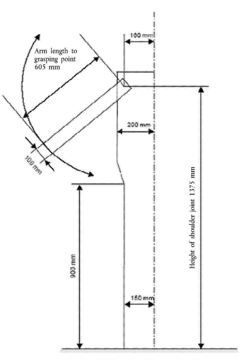
Figure 21
Reference wheelchair
(see Annex 8, paragraph 3.6.4)

Figure 22
Minimum clear space for the wheelchair user at the wheelchair space
(see Annex 8, paragraph 3.6.1)

Figure 23
Accessibility symbols
(see Annex 8, paragraphs 3.2.8 and 3.6.6)
Figure 23A
Pictogram for wheelchair users

Figure 23B
Pictogram for passengers with reduced mobility other than wheelchair users

Figure 24
(Reserved)
Figure 25
Passenger foot space
(see Annex 3, paragraph 7.7.1.6)

Figure 26
Roof escape hatch access
(see Annex 3, paragraph 7.7.4.1.1)

Figure 27
Access to driver’s door
(See Annex 3, paragraph 7.6.1.7.2)

Figure 28
Access to driver’s door
(See Annex 3, paragraph 7.6.1.9.3)

Figure 29
Example of a backrest for a rearward-facing wheelchair
(see Annex 8, paragraph 3.8.6)

(1) For vehicles of Class A or B, the lower panel may be displaced horizontally relative to the upper panel provided that it is in the same direction.
(2) The height of the upper cylinder and herewith the, overall height may be reduced by 100 mm in any part of the gangway to the rear of:
|
(a) |
a transverse plane situated 1,5 m forward of the centre line of the rear axle (foremost rear axle in the case of vehicles with more than one rear axle), and |
|
(b) |
a transverse vertical plane situated at the rear edge of the service door or of the rearmost service door if there are more than one service door. |
(3) The diameter of the lower cylinder may be reduced from 450 mm to 400 mm in any part of the gangway to the rear of the most forward of the following two planes:
|
(a) |
a transverse vertical plane situated 1,5 m forward of the centre line of the rear axle (foremost rear axle in the case of vehicles with more than one rear axle); and |
|
(b) |
a transverse vertical plane situated at the rear edge of the rearmost service door in between the axles. |
For the purpose of the above, each rigid section of an articulated vehicle shall be considered separately.
(4) 220 mm in the case of laterally movable seats (see paragraph 7.7.5.3).
(5) The overall height of the gauging device may be reduced (by reducing the height of the lower cylinder):
|
(a) |
from 1 800 mm to 1 680 mm in any part of the gangway of the lower deck to the rear of a transverse vertical plane situated 1 500 mm forward to the centre of the rear axle (foremost rear axle in the case of vehicles with more than one rear axle), |
|
(b) |
from 1 800 mm to 1 770 mm in the case of a service door which is situated forward the front axle in any part of the gangway situated between two transverse vertical planes situated 800 mm forwards and behind the centre line of the front axle. |
(6) 230 mm for vehicles having a capacity not exceeding 22 passengers.
(7) 700 mm in the case of an emergency door.
1 500 mm in the case of an emergency door in the upper deck of a double-deck vehicle.
850 mm maximum in the case of an emergency door in the lower deck of a double-deck vehicle.
(8) 430 mm in the case of a vehicle with solely mechanical suspension.
(9) For at least one service door; 400 mm for other service doors.
(10) 300 mm in the case of steps at a door behind the rearmost axle.
(11) 250 mm in gangways for vehicles having a capacity not exceeding 22 passengers.
(12) 225 for Class III.
(13) 350 mm at wheel arches and engine compartment.
(14) 400 mm in vehicles of Classes II and III.
ANNEX 5
(Reserved)
ANNEX 6
Guidelines for measuring the closing forces of power-operated doors
(see Annex 3, paragraph 7.6.5.6.1.1)
and the reactive forces of power-operated ramps
(see Annex 8, paragraph 3.11.4.3.3)
1. GENERAL
The closing of a power-operated door and the operation of a power-operated ramp are dynamic processes. When a moving door or ramp hits an obstacle, the result is a dynamic reaction force, the history of which (in time) depends on several factors (for example, mass of the door or ramp, acceleration, dimensions).
2. DEFINITIONS
|
2.1. |
Closing or reactive force F(t) is a time function, measured at the outer edge of the door or ramp (see paragraph 3.2 below). |
|
2.2. |
Peak force FS is the maximum value of the closing or reactive force. |
|
2.3. |
Effective force FE is the average value of the closing or reactive force related to the pulse duration:
|
|
2.4. |
Pulse duration T is the time between the t1 and t2: T = t2 – t1 where,
|
|
2.5. |
The relation between the above parameters is shown in figure 1 below (as an example): Figure 1
|
|
2.6. |
Clamping or mean reactive force Fc is the arithmetical mean value of the effective forces, measured at the same measuring point subsequently more times:
|
3. MEASUREMENTS
|
3.1. |
Conditions of measurement:
|
|
3.2. |
Measurement points shall be:
|
|
3.3. |
At least three measurements shall be taken at each of the measuring points to determine the clamping or mean reactive force according to paragraph 2.6. |
|
3.4. |
The signal of the closing or reactive force shall be recorded by means of a low-pass filter with a limiting frequency of 100 Hz. Both the threshold of sensitivity and the fade-away threshold to limit the pulse duration shall be set at 50 N. |
|
3.5. |
The deviation of the reading from the rated value shall not be more than ± 3 per cent. |
4. MEASURING DEVICE
|
4.1. |
The measuring device shall consist of two parts: one handle and one measuring part which is a load cell (see figure 2). |
|
4.2. |
The load cell shall have the following characteristics:
|
ANNEX 7
Alternative requirements for vehicles of Classes A and B
1. Vehicles of Classes A and B shall comply with the requirements of Annex 3 with the exception that:
|
(a) |
in place of paragraph 7.6.3.1 of Annex 3, a vehicle may comply with paragraph 1.1 of this Annex; |
|
(b) |
in place of paragraph 7.6.2 of Annex 3, a vehicle may comply with paragraph 1.2 of this Annex. |
1.1. Minimum dimensions for exits
The several kinds of exits shall have the following minimum dimensions:
|
Aperture |
Dimensions |
Remarks |
||||
|
Service Door |
Entry height: Class
|
The service door entry height shall be measured as the vertical distance measured on a vertical plane of the horizontal projections of the mid point of the door aperture and the top surface of the lowest step. |
||||
|
Aperture Height |
The vertical height of the service door aperture shall be such as to permit the free passage of the dual panel referred to in paragraph 7.7.1.1 of Annex 3. The upper corners may be reduced with round-offs, with a radius of not more than 150 mm. |
|||||
|
Width:
|
For Class B vehicles where the service door aperture height lies between 1 400 mm and 1 500 mm a minimum single door aperture width of 750 mm shall apply. For all the vehicles the width of any service door may be reduced by 100 mm when the measurement is made at the level of the handholds and by 250 mm in cases where intruding wheel arches or the actuating mechanism for automatic or remote-control doors or the rake of the windscreen so require. |
|||||
|
Emergency door |
|
The width may be reduced to 300 mm in cases where intruding wheel arches so require, providing that the width of 550 mm is respected at the minimum height of 400 mm above the lowest part of the door aperture. The upper corners may be reduced with round-offs, with a radius of not more than 150 mm. |
||||
|
Emergency Window |
Aperture area: 4 000 cm2 |
A 5 per cent tolerance shall, however, be permitted in respect of this area for type-approvals issued for one year following the entry into force of this Regulation. It shall be possible to inscribe in this area a rectangle of 500 mm × 700 mm. |
|
1.1.1. |
A vehicle to which paragraph 7.7.1.10 of Annex 3 applies shall meet the requirements of paragraph 7.6.3.1 of Annex 3 or paragraph 1.1 of this Annex as regards emergency windows and escape hatches, and the following minimum requirements as regards service doors and emergency doors:
|
1.2. Siting of exits
|
1.2.1. |
The service door(s) shall be situated on the side of the vehicle that is nearer to the side of the road corresponding to the direction of the traffic in the country in which the vehicle is to be registered, or in the rear face of the vehicle. |
|
1.2.2. |
The exits shall be placed in such a way that there is at least one exit on each side of the vehicle. |
|
1.2.3. |
The forward half and the rearward half of the passenger space shall each contain at least one exit. |
|
1.2.4. |
At least one exit shall be situated either in the rear face or in the front face of the vehicle unless an escape hatch is fitted. |
ANNEX 8
Requirements for technical devices facilitating access for passengers of reduced mobility
1. GENERAL
This Annex contains the provisions which apply to a vehicle designed for easy access for passengers with reduced mobility and wheelchair users.
2. SCOPE
These requirements shall apply to vehicles permitting easier access for persons with reduced mobility.
3. REQUIREMENTS
3.1. Steps
The height of the first step from the ground of at least one service door shall not exceed 250 mm for vehicles of Class I and A and 320 mm for vehicles of Class II, III and B. In the case where only one service door meets this requirement there must be no barrier or sign which prevents that door from being used as both an entrance and an exit.
As an alternative for vehicles of Class I and A, the first step from the ground shall not exceed 270 mm in two door openings, one entrance and one exit.
A kneeling system and/or retractable step may be engaged.
The height of steps in an access passage at the above-mentioned door(s), and in the gangway, shall be not more than 200 mm for vehicles of Class I and A and 250 mm for vehicles of Class II, III and B.
The transition from a sunken gangway to a seating area shall not be considered to be a step.
3.2. Priority seats and space for passengers with reduced mobility
3.2.1. (Reserved)
3.2.2. There shall be adequate space for a guide dog under, or adjacent to, at least one of the priority seats. This space shall not form a part of the gangway.
3.2.3. Armrests shall be fitted on seats between the seating position and the gangway and shall be capable of being moved easily out of the way to permit clear access to the seat. In the case of seats facing each other one of the gangway seats may alternatively be fitted with a vertical stanchion. This stanchion shall be positioned so that the seat occupant is kept securely on the seat and easy access to the seat is possible.
3.2.4. The minimum width of a priority seat cushion, measured from a vertical plane passing through the centre of that seating position, shall be 220 mm on each side.
3.2.5. The height of the uncompressed seat cushion relative to the floor shall be such that the distance from the floor to a horizontal plane tangent to the front upper surface of the seat cushion is between 400 mm and 500 mm.
3.2.6. The foot space at priority seating positions shall extend forward of the seat from a vertical plane through the forward edge of the seat cushion. The foot space shall not have a slope in any direction of more than 8 per cent.
3.2.7. Each priority seating position shall have a free height of not less than 1 300 mm for vehicles of Class I and A and 900 mm for vehicles of Class II, measured from the highest point of the uncompressed seat cushion. This free height shall extend over the vertical projection of the whole of the seat and the associated foot space.
Intrusion of a seat back or other object into this space shall be permitted provided that a minimum clear vertical space extending 230 mm in front of the seat cushion is maintained. Where the priority seat is positioned facing a bulkhead more than 1 200 mm in height this space shall be 300 mm. From the edges of the free space defined above, intrusions are permitted in accordance with paragraphs 7.7.8.6.3.1 to 7.7.8.6.3.4 of Annex 3 as if reference to the clear space in paragraphs 7.7.8.6.1 and 7.7.8.6.2 of Annex 3 is a reference to the clear space defined above. The provisions of paragraph 7.7.8.1.4 of Annex 3 may apply. Intrusions of handholds or handrails as mentioned in paragraph 3.4.2 may protrude by a maximum of 100 mm from the sidewall into the clear space over the vertical projection of the foot space.
3.2.8. Vehicles fitted with a priority seat shall have pictogram(s) in accordance with Annex 4, figure 23B visible from the outside, both on the front nearside of the vehicle and adjacent to the relevant service door(s). A pictogram shall be placed internally adjacent to the priority seat.
3.3. Communication devices
3.3.1. Communication devices shall be placed adjacent to any priority seat and within any wheelchair area and shall be at a height between 700 mm and 1 200 mm above the floor.
3.3.2. Communication devices situated in the low floor area shall be at a height between 800 mm and 1 500 mm where there are no seats.
3.3.3. (Reserved)
3.3.4. If a vehicle is fitted with a ramp or lift, a means of communication with the driver shall be fitted outside, adjacent to the door, and at a height between 850 mm and 1 300 mm from the ground. This requirement shall not apply to a door situated in the direct field of vision of the driver.
3.4. Handrails to priority seating
3.4.1. A handrail at a height of between 800 mm and 900 mm above the floor level shall be provided between the priority seats as described in paragraph 7.7.8.5.3 of Annex 3 and at least one service door suitable for boarding and alighting. A break is permitted where it is necessary to gain access to a wheelchair space, a seat located at a wheel arch, a staircase, an access passage or a gangway. Any break in the handrail shall not exceed 1 050 mm and a vertical handrail shall be provided on at least one side of the break.
3.4.2. Handrails or handholds shall be placed adjacent to priority seating positions to facilitate entry and exit of the seat, and shall be designed in such a way as to allow the passenger to grasp them easily.
3.5. Floor slope
The slope of any gangway, access passage or floor area between any priority seat or wheelchair space and at least one entrance and one exit or a combined entrance and exit shall not exceed 8 per cent. Such sloping areas shall be provided with a slip-resistant surface.
3.6. Wheelchair accommodation provisions
3.6.1. For each wheelchair user provided for in the passenger compartment there shall be a special area at least 750 mm wide and 1 300 mm long. The longitudinal plane of the special area shall be parallel to the longitudinal plane of the vehicle and the floor surface of the special area shall be slip resistant and the maximum slope in any direction shall not exceed 5 per cent. In the case of a rearward facing wheelchair complying with the requirements specified in paragraph 3.8.4, the slope in the longitudinal direction shall not exceed 8 per cent provided that this slope inclines upwards from the front end to the rear end of the special area.
In the case of a wheelchair space designed for a forward facing wheelchair, the top of preceding seat-backs may intrude into the wheelchair space if a clear space is provided as shown in Annex 4, Figure 22.
3.6.2. There shall be at least one doorway through which wheelchair users can pass. In the case of vehicles of Class I, at least one wheelchair access door shall be a service door. The wheelchair access door shall bear a boarding device complying with the provisions of paragraph 3.11.3 (a lift) or 3.11.4 (a ramp).
3.6.3. A door for wheelchair access, that is not a service door, shall have a minimum height of 1 400 mm. The minimum width of all doors providing wheelchair access to the vehicle shall be 900 mm which may be reduced by 100 mm when the measurement is made at the level of handholds.
3.6.4. It shall be possible for a wheelchair user to move freely and easily from the outside of the vehicle through at least one of the doors for wheelchair access into the special area(s) with the reference wheelchair, the dimensions of which are shown in Annex 4, figure 21.
3.6.4.1. By ‘moving freely and easily’, it is meant that there exists:
|
(a) |
sufficient space available for the wheelchair user to manoeuvre without the assistance of a person; |
|
(b) |
there are no steps, gaps or stanchions which could be an obstacle to the free movement of the wheelchair user. |
3.6.4.2. For the application of the above provisions, the test shall be performed, in the case of vehicles of Class I and A fitted with more than one wheelchair space, for each wheelchair space with all other wheelchair spaces occupied by the reference wheelchair.
3.6.5. In vehicles of Class I and A fitted with a ramp for wheelchair access, it shall be possible for a reference wheelchair having the dimensions shown in Annex 4, figure 21 to enter and exit a vehicle with the wheelchair moving in a forward direction.
3.6.6. Vehicles fitted with a wheelchair space shall have pictogram(s) in accordance with Annex 4, figure 23A visible from the outside, both on the front nearside of the vehicle and adjacent to the relevant service door(s).
One of these pictograms shall be placed internally adjacent to each wheelchair space indicating whether the wheelchair is to be positioned facing the front or the rear of the vehicle.
3.7. Seats and standing passengers in the wheelchair space
3.7.1. Folding seats may be fitted in a wheelchair space. However, such seats when folded and out of use shall not intrude into the wheelchair space.
3.7.2. A vehicle may be equipped with demountable seats fitted in the wheelchair space provided that such seats may be easily removed by the driver or a crew member.
3.7.3. For vehicles of Class I, II and A, where the foot space of any seat, or part of a folding seat when in use, intrudes into a wheelchair space, those seats shall have signs fixed on or adjacent to them with the following text, equivalent text or pictogram:
‘Please give up this space for a wheelchair user’.
The provisions of paragraph 7.6.11.4 of Annex 3 apply to any textual markings used.
3.7.4. In vehicles where any wheelchair space is designated for use exclusively by a wheelchair user as provided for in paragraph 7.2.2.2.10 of Annex 3, those spaces shall be clearly marked with the following text, equivalent text or pictogram:
‘Area designated for use exclusively by a wheelchair user’
The provisions of paragraph 7.6.11.4 of Annex 3 apply to any textual markings used.
3.8. Stability of wheelchairs
3.8.1. In vehicles required to have occupant restraint systems fitted, the wheelchair space shall be designed for the wheelchair user to travel facing forwards and shall be fitted with restraint systems complying with either the requirements specified in paragraph 3.8.2 or those specified in paragraph 3.8.3.
In vehicles not required to have occupant restraint systems fitted, the wheelchair space shall be fitted with restraint systems complying with the requirements specified in paragraph 3.8.2 or 3.8.3, or shall comply with the requirements specified in paragraph 3.8.4.
3.8.2. Forward-facing wheelchair — static test requirements
3.8.2.1. Each wheelchair space shall be provided with a restraint system capable of restraining the wheelchair and the wheelchair user.
3.8.2.2. This restraint system and its anchorages shall be designed to withstand forces equivalent to the ones required for the passenger seats and occupant restraint systems.
3.8.2.3. A static test shall be carried out in accordance with the following requirements:
|
3.8.2.3.1. |
the forces referred hereto shall be applied in forward and rearward directions, separately and on the restraint system itself; |
|
3.8.2.3.2. |
the force shall be maintained for a period of not less than 0,2 seconds; |
|
3.8.2.3.3. |
the restraint system shall be capable of withstanding the test. Permanent deformation, including partial rupture or breakage of the restraint system shall not constitute failure if the required force is sustained for the specified time. Where applicable, the locking device enabling the wheelchair to leave the vehicle shall be operable by hand after removal of the traction force. |
3.8.2.4. In forward direction in the case of a separate wheelchair and wheelchair user restraint system
3.8.2.4.1. For category M2:
|
3.8.2.4.1.1. |
1 110 ± 20 daN in the case of a lap belt. The force shall be applied on the wheelchair user restraint system in the horizontal plane of the vehicle and towards the front of the vehicle if the restraint system is not attached to the floor of the vehicle. If the restraint system is attached to the floor, the force shall be applied in an angle of 45 ± 10 degrees to the horizontal plane of the vehicle and towards the front of the vehicle; |
|
3.8.2.4.1.2. |
675 ± 20 daN in the horizontal plane of the vehicle and towards the front of the vehicle on the lap portion of the belt and 675 ± 20 daN in the horizontal plane of the vehicle and towards the front of the vehicle on the torso portion of the belt in the case of 3-point belt; |
|
3.8.2.4.1.3. |
1 715 ± 20 daN in an angle of 45 ± 10 degrees to the horizontal plane of the vehicle and towards the front of the vehicle on the wheelchair restraint system; |
|
3.8.2.4.1.4. |
the forces shall be applied simultaneously. |
3.8.2.4.2. For category M3:
|
3.8.2.4.2.1. |
740 ± 20 daN in the case of a lap belt. The force shall be applied on the wheelchair user restraint system in the horizontal plane of the vehicle and towards the front of the vehicle if the restraint system is not attached to the floor of the vehicle. If the restraint system is attached to the floor, the force shall be applied in an angle 45 ± 10 degrees to the horizontal plane of the vehicle and towards the front of the vehicle; |
|
3.8.2.4.2.2. |
450 ± 20 daN in the horizontal plane of the vehicle and towards the front of the vehicle on the lap portion of the belt and 450 ± 20 daN in the horizontal plane of the vehicle and towards the front of the vehicle on the torso portion of the belt in the case of 3-point belt; |
|
3.8.2.4.2.3. |
1 130 ± 20 daN in an angle of 45 ± 10 degrees to the horizontal plane of the vehicle and towards the front of the vehicle on the wheelchair restraint system; |
|
3.8.2.4.2.4. |
the forces shall be applied simultaneously. |
3.8.2.5. In forward direction in the case of a combined wheelchair and wheelchair user restraint system.
3.8.2.5.1. For category M2;
|
3.8.2.5.1.1. |
1 110 ± 20 daN in an angle of 45 ± 10 degrees to the horizontal plane of the vehicle and towards the front of the vehicle on the wheelchair user restraint system in the case of a lap belt; |
|
3.8.2.5.1.2. |
675 ± 20 daN in an angle of 45 ± 10 degrees to the horizontal plane of the vehicle and towards the front of the vehicle on the lap portion of the belt and 675 ± 20 daN in the horizontal plane of the vehicle and towards the front of the vehicle on the torso portion of the belt in the case of 3-point belt; |
|
3.8.2.5.1.3. |
1 715 ± 20 daN in an angle of 45 ± 10 degrees to the horizontal plane of the vehicle and towards the front of the vehicle on the wheelchair restraint system; |
|
3.8.2.5.1.4. |
the forces shall be applied simultaneously. |
3.8.2.5.2. For category M3:
|
3.8.2.5.2.1. |
740 ± 20 daN in an angle of 45 ± 10 degrees to the horizontal plane of the vehicle and towards the front of the vehicle on the wheelchair user restraint system in the case of a lap belt; |
|
3.8.2.5.2.2. |
450 ± 20 daN in an angle of 45 ± 10 degrees to the horizontal plane of the vehicle and towards the front of the vehicle on the lap portion of the belt and 450 ± 20 daN in the horizontal plane of the vehicle and towards the front of the vehicle on the torso portion of the belt in the case of 3-point belt; |
|
3.8.2.5.2.3. |
1 130 ± 20 daN in an angle of 45 ± 10 degrees to the horizontal plane of the vehicle and towards the front of the vehicle on the wheelchair restraint system; |
|
3.8.2.5.2.4. |
the forces shall be applied simultaneously. |
3.8.2.6. In rearward direction:
|
3.8.2.6.1. |
810 ± 20 daN in an angle of 45 ± 10 degrees to the horizontal plane of the vehicle and towards the rear of the vehicle on the wheelchair restraint system. |
3.8.2.7. In every case the forces shall be applied to the wheelchair user restraint system by means of a traction device appropriate to the belt type as specified in Regulation No 14.
3.8.3. Forward-facing wheelchair — hybrid test requirements
3.8.3.1. A wheelchair space shall be fitted with a wheelchair restraint system suitable for general wheelchair application and shall allow the carriage of a wheelchair and a wheelchair user facing the front of the vehicle;
3.8.3.2. A wheelchair space shall be fitted with a wheelchair user restraint system which shall comprise of a minimum of two anchorage points and a pelvic restraint (lap belt) designed and constructed of components intended to perform in a similar manner to those of a seat belt conforming to Regulation No 16;
3.8.3.3. Any restraint system fitted to a wheelchair space shall be capable of being easily released in the case of an emergency;
3.8.3.4. Any wheelchair restraint system shall either:
|
3.8.3.4.1. |
meet the dynamic test requirements described in paragraph 3.8.3.8 and be securely attached to vehicle anchorages meeting the static test requirements in paragraph 3.8.3.6; or |
|
3.8.3.4.2. |
be securely attached to vehicle anchorages such that the combination of restraint and anchorages meets the requirements of paragraph 3.8.3.8. |
3.8.3.5. Any wheelchair user restraint shall either:
|
3.8.3.5.1. |
meet the dynamic test requirements described in paragraph 3.8.3.9 and be securely attached to vehicle anchorages meeting the static test requirements in paragraph 3.8.3.6; or |
|
3.8.3.5.2. |
be securely attached to vehicle anchorages such that the combination of restraint and anchorages meets the dynamic test requirements described in paragraph 3.8.3.9 when attached to anchorages set up as described in paragraph 3.8.3.6.7. |
3.8.3.6. A static test shall be carried out on the anchorage points for both the wheelchair restraint system and the wheelchair user restraint in accordance with the following requirements:
|
3.8.3.6.1. |
the forces specified in paragraph 3.8.3.7 shall be applied by means of a device reproducing the geometry of the wheelchair restraint system; |
|
3.8.3.6.2. |
the forces specified in paragraph 3.8.3.7.3 shall be applied by means of a device reproducing the geometry of the wheelchair user restraint and by means of a traction device specified in Regulation No 14. |
|
3.8.3.6.3. |
the forces in paragraph 3.8.3.6.1 and paragraph 3.8.3.6.2 shall be applied simultaneously in the forward direction and at an angle of 10 ± 5 degrees above the horizontal plane; |
|
3.8.3.6.4. |
the forces in paragraph 3.8.3.6.1 shall be applied in the rearward direction and at an angle of 10 ± 5 degrees above the horizontal plane; |
|
3.8.3.6.5. |
the forces shall be applied as rapidly as possible through the central vertical axis of the wheelchair space; and |
|
3.8.3.6.6. |
the force shall be maintained for a period of not less than 0,2 seconds. |
|
3.8.3.6.7. |
the test shall be carried out on a representative section of the vehicle structure together with any fitting provided in the vehicle which is likely to contribute to the strength or rigidity of the structure. |
3.8.3.7. The forces specified in paragraph 3.8.3.6 are:
|
3.8.3.7.1. |
in the case of anchorages provided for a wheelchair restraint system fitted to a category M2 vehicle:
|
|
3.8.3.7.2. |
in the case of anchorages provided for a wheelchair restraint system fitted to a category M3 vehicle
|
|
3.8.3.7.3. |
in the case of anchorages provided for a wheelchair user restraint system the forces shall be in accordance with the requirements of Regulation No 14. The forces shall be applied by means of a traction device as appropriate to the belt type as specified in Regulation No 14. |
3.8.3.8. A wheelchair restraint system shall be subject to a dynamic test carried out in accordance with the following requirements:
|
3.8.3.8.1. |
a representative wheelchair test trolley of mass 85 kg shall, from a speed of between 48 km/h to 50 km/h to rest, be subject to a deceleration-time pulse:
|
|
3.8.3.8.2. |
a representative wheelchair test trolley of mass 85 kg shall, from a speed of between 48 km/h to 50 km/h to rest, be subject to a deceleration-time pulse:
|
|
3.8.3.8.3. |
the test in paragraph 3.8.3.8.2 shall not apply if the same restraints are used for the forward and rearward direction or if an equivalent test has been conducted; |
|
3.8.3.8.4. |
for the above test, the wheelchair restraint system shall be attached to either:
|
3.8.3.9. A wheelchair user restraint shall comply with the test requirements specified in Regulation No 16 or an equivalent test to the deceleration-time pulse in paragraph 3.8.3.8.1. A seat belt approved to Regulation No 16 and so marked shall be deemed to comply.
3.8.3.10. A test in paragraph 3.8.3.6, 3.8.3.8 or 3.8.3.9 shall be deemed to have failed unless the following requirements are met:
|
3.8.3.10.1. |
no part of the system shall have failed, or shall have become detached from its anchorage or from the vehicle during the test; |
|
3.8.3.10.2. |
mechanisms to release the wheelchair and user shall be capable of release after completion of the test; |
|
3.8.3.10.3. |
in the test in paragraph 3.8.3.8 the wheelchair shall not move more than 200 mm in the longitudinal plane of the vehicle during the test; |
|
3.8.3.10.4. |
no part of the system shall be deformed to such an extent after completion of the test that, because of sharp edges or other protrusions, the part is capable of causing injury. |
3.8.3.11. Its operating instructions shall be clearly displayed adjacent to it.
3.8.4. Rearward facing wheelchair — static test requirements
3.8.4.1. Vehicles not required to have occupant restraint systems fitted may, as an alternative to the provisions of paragraph 3.8.2 or 3.8.3, be provided with a wheelchair space designed for the wheelchair user to travel unrestrained with the wheelchair facing rearwards against a support or backrest, in accordance with the following provisions:
|
3.8.4.1.1. |
one of the longitudinal sides of the space for a wheelchair shall rest against a side or wall of the vehicle or a partition; |
|
3.8.4.1.2. |
a support or backrest perpendicular to the longitudinal axis of the vehicle shall be provided in the forward end of the wheelchair space; |
|
3.8.4.1.3. |
the support or backrest shall be designed for the wheels or the back of the wheelchair to rest against the support or backrest in order to avoid the wheelchair from tipping over and shall comply with the provisions of paragraph 3.8.5; |
|
3.8.4.1.4. |
a handrail or handhold shall be fitted to the side or wall of the vehicle or a partition in such a way to allow the wheelchair user to grasp it easily. This handrail shall not extend over the vertical projection of the wheelchair space, except by not more than 90 mm and only at a height not less than 850 mm above the floor of the wheelchair space; |
|
3.8.4.1.5. |
a retractable handrail or any equivalent rigid device shall be fitted on the opposite side of the wheelchair space in order to restrict any lateral shift of the wheelchair and to allow the wheelchair user to grasp it easily; |
|
3.8.4.1.6. |
a sign shall be fixed adjacent to the wheelchair area with the following text: ‘This space is reserved for a wheelchair. The wheelchair must be placed facing rearwards resting against the support or backrest with the brakes on’. The provisions of paragraph 7.6.11.4 of Annex 3 apply to any textual markings used. |
3.8.5. Backrest and support requirements
3.8.5.1. A backrest fitted to a wheelchair space in accordance with paragraph 3.8.4 shall be fitted perpendicular to the longitudinal axis of the vehicle and shall be capable of bearing a load of 250 ± 20 daN applied to the centre of the padded surface of the backrest, at a height of not less than 600 mm and of not more than 800 mm measured vertically from the floor of the wheelchair space, for a minimum of 1,5 seconds by means of a block 200 mm × 200 mm in the horizontal plane of the vehicle towards the front of the vehicle. The backrest shall not deflect more than 100 mm or suffer permanent deformation or damage.
3.8.5.2. A support fitted to a wheelchair space in accordance with paragraph 3.8.4 shall be fitted perpendicular to the longitudinal axis of the vehicle and shall be capable of withstanding a force of 250 ± 20 daN applied to the centre of the support, for a minimum of 1,5 seconds in the horizontal plane of the vehicle towards the front of the vehicle in the middle of the support. The support shall not deflect more than 100 mm or suffer permanent deformation or damage.
3.8.6. Example of a backrest meeting the requirements of paragraph 3.8.4.1.3 (See Annex 4, figure 29).
3.8.6.1. The bottom edge of a backrest shall be at a height of not less than 350 mm and of not more than 480 mm measured vertically from the floor of the wheelchair space.
3.8.6.2. The top edge of a backrest shall be at a height of not less than 1 300 mm measured vertically from the floor of the wheelchair space.
3.8.6.3. A backrest shall have a width of:
|
3.8.6.3.1. |
not less than 270 mm and of not more than 420 mm up to a height of 830 mm measured vertically from the floor of the wheelchair space, and |
|
3.8.6.3.2. |
not less than 270 mm and of not more than 300 mm at heights exceeding 830 mm measured vertically from the floor of the wheelchair space. |
3.8.6.4. A backrest shall be fitted at an angle of not less than four degrees and of not more than eight degrees to the vertical with the bottom edge of the backrest positioned closer to the rear of the vehicle than the top edge.
3.8.6.5. The padded surface of a backrest shall form a single and continuous plane.
3.8.6.6. The padded surface of a backrest shall pass through any point on an imaginary vertical plane situated to the rear of the front end of the wheelchair space and situated not less than 100 mm and not more than 120 mm from the front end of the wheelchair space measured horizontally and not less than 830 mm and not more than 870 mm from the floor of the wheelchair space measured vertically.
3.9. Door controls
3.9.1. If a door referred to in paragraph 3.6 is fitted with opening controls for use under normal circumstances, these controls shall:
|
3.9.1.1. |
in the case of exterior controls, be on or adjacent to that door at a height between 850 mm and 1 300 mm from the ground and be not more than 900 mm from the door, and |
|
3.9.1.2. |
in the case of interior controls in vehicles of Class I, II and III, be on or adjacent to that door at a height of between 850 mm and 1 300 mm from the upper surface of the floor nearest the control and be not more than 900 mm in any direction from the door aperture. |
3.10. (Reserved)
3.11. Provisions for boarding devices
3.11.1. General requirements:
3.11.1.1. The controls actuating the boarding devices shall be clearly marked as such. The extended or lowered position of the boarding device shall be indicated by a tell-tale to the driver.
3.11.1.2. In the event of the failure of a safety device, lifts, ramps and kneeling systems shall be incapable of operation, unless they can be safely operated by manual effort. The type and location of the emergency operating mechanism shall be clearly marked. In the event of power failure, lifts and ramps must be capable of manual operation.
3.11.1.3. Access to one of the service or emergency doors on the vehicle may be obstructed by a boarding device providing the following two conditions are satisfied from both inside and outside the vehicle.
3.11.1.3.1. The boarding device does not obstruct the handle or other device for opening the door.
3.11.1.3.2. The boarding device can be readily moved to leave the doorway clear for use in an emergency.
3.11.2. Kneeling system
3.11.2.1. A switch shall be required to enable operation of the kneeling system.
3.11.2.2. Any control which initiates the lowering or raising of any part or the whole of the bodywork relative to the road surface must be clearly identified and be under the direct control of the driver.
3.11.2.3. The lowering process shall be capable of being stopped and immediately reversed by a control both within the reach of the driver, whilst seated in the cab, and also adjacent to any other operating controls provided for the operation of the kneeling system.
3.11.2.4. Any kneeling system that is fitted to a vehicle shall not allow the vehicle to be driven at a speed of more than 5 km/h when the vehicle is lower than the normal height of travel.
3.11.3. Lift
3.11.3.1. General provisions
3.11.3.1.1. Lifts shall only be capable of operation when the vehicle is at standstill. Any movement of the platform shall be prevented unless a device preventing the wheelchair from rolling off has been activated or has automatically come into operation.
3.11.3.1.2. The lift platform shall not be less than 800 mm wide, and not less than 1 200 mm long and shall be capable of operating when carrying a mass of at least 300 kg.
3.11.3.2. Additional technical requirements for power-operated lifts
3.11.3.2.1. The operating control shall be designed in such a way that, if released, it automatically returns to the off position. As it does so the movement of the lift shall immediately be stopped and it shall be possible to initiate a movement in either direction.
3.11.3.2.2. A safety device (e.g. reversing mechanism) shall protect areas not visible to the operator, where the movement of the lift might trap or crush objects.
3.11.3.2.3. In the event of one of these safety devices coming into operation, the movement of the lift shall immediately be stopped and movement in the opposite direction initiated.
3.11.3.3. Operation of power operated lifts
3.11.3.3.1. Where the lift is at a service door situated within the direct field of vision of the driver of the vehicle, the lift may be operated by the driver when in the driver’s seat.
3.11.3.3.2. In all others cases, the controls shall be adjacent to the lift. They shall be capable of being activated and deactivated only by the driver from his seat.
3.11.3.4. Manually operated lift
3.11.3.4.1. The lift shall be designed for operation by controls adjacent to the lift.
3.11.3.4.2. The lift shall be so designed that excessive forces are not required to operate it.
3.11.4. Ramp
3.11.4.1. General provisions
3.11.4.1.1. The ramp shall only be capable of operation when the vehicle is at standstill.
3.11.4.1.2. Edges on the outside shall be rounded to a radius of no less than 2,5 mm. Corners on the outside shall be rounded to a radius of not less than 5 mm.
3.11.4.1.3. The useable surface of a ramp shall be at least 800 mm wide. The slope of the ramp, when extended or folded out on to a kerb of 150 mm in height, should not exceed 12 per cent. The slope of the ramp, when extended or folded out to the ground, should not exceed 36 per cent. A kneeling system may be used to achieve this test.
3.11.4.1.4. Any ramp which when ready for use exceeds 1 200 mm in length shall be fitted with a device to prevent the wheelchair rolling off the sides.
3.11.4.1.5. Any ramp shall be capable of operating safely with a load of 300 kg.
3.11.4.1.6. The outer edge of ramp surfaces available for use by a wheelchair shall be clearly marked with a band of colour 45 mm to 55 mm in width which contrasts visually with the remainder of the ramp surface. The band of colour shall extend along the outermost edge and along both edges parallel to the direction of travel of the wheelchair.
Marking of any trip hazard or where part of the ramp surface also forms part of the step is permissible.
3.11.4.1.7. A portable ramp must be secure when in its position for use. A portable ramp must be provided with a suitable position where it can be safely stowed and where it is readily available for use.
3.11.4.2. Modes of operation
3.11.4.2.1. Deployment and stowage of the ramp may be either manual or power-operated.
3.11.4.3. Additional technical requirements for power-operated ramps
3.11.4.3.1. Deployment and stowage of the ramp shall be indicated by flashing yellow lights and an audible signal.
3.11.4.3.2. Deployment and stowage of the ramp that may create a risk of injury shall be protected by a safety device(s).
3.11.4.3.3. These safety devices shall stop the movement of the ramp when the ramp is subject to a mean reactive force not exceeding 150 N. The peak force may be higher than 150 N for a short time provided that it does not exceed 300 N. The reactive force may be measured by any method to the satisfaction of the competent authority. Guidelines for measuring the reactive forces are given in Annex 6 to this Regulation.
3.11.4.3.4. The horizontal movement of a ramp shall be interrupted when a mass of 15 kg is placed upon it.
3.11.4.4. Operation of power-operated ramps
3.11.4.4.1. Where the driver has adequate view of the ramp sufficient to monitor its deployment and use, to ensure the safety of passengers, the ramp may be operated by the driver when in the driver’s seat. This requirement may be met by a suitable indirect vision device(s).
3.11.4.4.2. In all others cases, the controls shall be adjacent to the ramp. They shall be capable of being activated and deactivated only by the driver from his seat.
3.11.4.5. Operation of manually-operated ramp
3.11.4.5.1. The ramp shall be so designed that excessive forces are not required to operate the ramp.
ANNEX 9
(Reserved)
ANNEX 10
Type-approval for a separate technical unit and type-approval of a vehicle fitted with a bodywork already approved as a separate technical unit
1. SEPARATE TECHNICAL UNIT TYPE-APPROVAL
|
1.1. |
In order to be granted separate technical unit type-approval to this Regulation for a vehicle bodywork, the manufacturer must demonstrate to the satisfaction of the Approval Authority the accomplishment of the conditions declared by the manufacturer. The remaining conditions to this Regulation must be accomplished and demonstrated according to paragraph 2. |
|
1.2. |
Approval may be granted subject to conditions to be met by the completed vehicle (such as, for example, characteristics of suitable chassis, restriction on use or installation), these restrictions being recorded on the approval certificate. |
|
1.3. |
Any such conditions must be communicated to the purchaser of the vehicle bodywork or the next stage builder of the vehicle in an appropriate form. |
2. TYPE-APPROVAL OF A VEHICLE FITTED WITH A BODYWORK ALREADY APPROVED AS A SEPARATE TECHNICAL UNIT
|
2.1. |
In order to be granted type-approval to this Regulation for a vehicle fitted with a bodywork which has already been granted approval as a separate technical unit, the manufacturer must demonstrate to the satisfaction of the Approval Authority compliance with the requirements of this Regulation that would not have already been accomplished and demonstrated according to paragraph 1, considering any previous type-approval as uncompleted vehicle. |
|
2.2. |
Any requirements established according to paragraph 1.2 must be fulfilled. |
ANNEX 11
MASSES AND DIMENSIONS
1. This Annex applies to the masses and dimensions of vehicles of categories M2 and M3 in so far as they are necessary for the approval of a vehicle in respect of its general construction.
2. DEFINITIONS
For the purposes of this Annex:
|
2.1. |
‘Group of axles’ means axles being part of a bogie. A two-axle group is called a tandem and a tri-axle group a tri-axle bogie. By convention, a solo axle is considered as a group of one axle. |
|
2.2. |
‘Vehicle dimensions’ means the dimensions of the vehicle based on its construction, as stated by the manufacturer.
|
|
2.3. |
‘Technically permissible maximum mass on the axle (m)’ means the mass corresponding to the maximum permissible static vertical load exerted by the axle on the road surface, based on the construction of the vehicle and of the axle and as stated by the vehicle manufacturer. |
|
2.4. |
‘Technically permissible maximum mass on a group of axles (μ)’ means the mass corresponding to the maximum permissible static vertical load exerted by the group of axles on the road surface, based on both the construction of the vehicle and of the group of axles and as stated by the vehicle manufacturer. |
|
2.5. |
‘Towable mass’ means the total load exerted on the road surface by the axle(s) of the towed vehicle(s). |
|
2.6. |
‘Technically permissible maximum towable mass (TM)’ means the maximum towable mass stated by the manufacturer. |
|
2.7. |
‘Technically permissible maximum mass on the coupling point of a vehicle’ means the mass corresponding to the maximum permissible static vertical load on the coupling point based on the construction of the vehicle and/or coupling device and as stated by the manufacturer. By definition, this mass does not include the mass of the coupling device of the vehicle. |
|
2.8. |
‘Technically permissible maximum laden mass of the combination (MC)’ means the total mass of a combination of vehicle and trailer(s) as stated by the manufacturer. |
|
2.9. |
‘Axle-lift device’ means a device permanently fitted to a vehicle for the purpose of reducing or increasing the load on the axle(s), according to the loading conditions of the vehicle:
in order to reduce the wear on the tyres when the vehicle is not fully laden, and/or make starting (moving off) on slippery ground easier for vehicles or vehicle combinations, by increasing the load on the driving axle. |
3. REQUIREMENTS
3.1. Measurement of the mass of the vehicle in running order and of its distribution among the axles
The mass of the vehicle in running order and its distribution on the axles are measured on the vehicle(s) submitted in accordance with paragraph 3.4 of this Regulation placed in a stationary position with their wheels set straight ahead. If the measured masses differ by no more than 3 per cent from the masses stated by the manufacturer for the corresponding technical configurations within the type, or by no more than 5 per cent if the vehicle is of category M2 not exceeding 3 500 kg, the masses in running order and their distribution among the axles as stated by the manufacturer are used for the purpose of the requirements below. Otherwise the measured masses shall be used and the technical service may then, if necessary, carry out additional measurements on vehicle(s) other than those submitted in accordance with paragraph 3.4 of this Regulation.
3.2. Mass distribution calculations
3.2.1. Calculation procedure
|
3.2.1.1. |
For the purpose of the mass distribution calculations hereafter laid down, the manufacturer shall provide the technical service in charge of the tests, with the information (in tabular or any other appropriate form) necessary to identify for each technical configuration within the vehicle type the corresponding technically permissible maximum laden mass of the vehicle, the technically permissible maximum masses on the axles and groups of axles, the technically permissible maximum towable mass, and the technically permissible maximum laden mass of the combination. |
|
3.2.1.2. |
Suitable calculations shall be carried out in order to make sure that the following requirements are fulfilled for each technical configuration within the type. For this purpose, the calculations may be limited to the worst cases. |
|
3.2.1.3. |
In the following requirements, the notations M, mi, μj TM, and MC respectively designate the following parameters, for which the requirements of paragraph 3.2 shall be fulfilled:
|
|
3.2.1.4. |
In the case of a solo axle, designated ‘i’ as an axle and ‘j’ as a group of axles, mi = μj by definition. |
|
3.2.1.5. |
In the case of vehicles fitted with loadable axles, the calculations required by paragraph 3.2.1.2 shall be carried out with the suspension of the axles loaded in the normal running configuration. In the case of vehicles fitted with retractable axles, the calculations required by paragraph 3.2.1.2 shall be carried out with the axles lowered. |
|
3.2.1.6. |
For groups of axles, the manufacturer shall indicate the laws of distribution among the axles of the total mass applied to the group (for instance by stating the distribution formulae or producing distribution graphs). |
3.2.2. Loading limitations
|
3.2.2.1. |
The sum of the masses mi shall not be less than the mass M. |
|
3.2.2.2. |
For each group of axles designated ‘j’, the sum of the masses mi on its axles shall not be less than the mass μj. In addition, each of the masses mi shall not be less than the part of μj applying on the axle ‘i’ as determined by the mass distribution laws for that group of axles. |
|
3.2.2.3. |
The sum of the masses μj shall not be less than the mass M. |
|
3.2.2.4. |
MC shall not exceed M + TM. |
3.2.3. Loading conditions
|
3.2.3.1. |
The mass of the vehicle in running order, plus the mass Q multiplied by the number of seated and standing passengers, plus the masses WP, B and BX as defined in paragraph 3.2.3.2.1, plus the technical permissible maximum mass on the coupling point, if a coupling is fitted by the manufacturer, shall not exceed the mass M. |
|
3.2.3.2. |
When the vehicle in running order is laden as described in paragraph 3.2.3.2.1, the mass corresponding to the load on each axle shall not exceed the mass mi on each axle, and the mass corresponding to the load on each solo axle or group of axles shall not exceed the mass μj on that group of axles. Moreover, the mass corresponding to the load on the driving axle or the sum of masses, corresponding to the loads on the driving axles shall be at least 25 per cent of M. |
|
3.2.3.2.1. |
The vehicle in running order is loaded with: a mass corresponding to the number P of seated passengers, of mass Q; a mass corresponding to the number SP of standing passengers, of mass Q uniformly distributed over the surface available for standing passengers S1; where appropriate, a mass WP uniformly distributed over each wheelchair space; a mass equal to B (kg) uniformly distributed in the baggage compartments; a mass equal to BX (kg) uniformly distributed over the surface area of the roof equipped for the carriage of baggage, where: P is the number of seated passengers. S1 is the area for standing passengers. In the case of vehicles of Classes III or B, S1 = 0. SP, declared by the manufacturer, shall not exceed the value S1/SSp, where SSp is the conventional space provided for one standing passenger specified in the table below. WP (kg), is the number of wheelchair spaces multiplied by 250 kg representing the mass of a wheelchair and user. B (kg), declared by the manufacturer, shall have a numeric value not less than 100 × V. This shall include baggage compartments or racks that may be attached to the outside of the vehicle. V is the total volume of baggage compartments in m3. When approving a vehicle of Class I or A, the volume of baggage compartments accessible only from the outside of the vehicle shall be disregarded. BX, declared by the manufacturer, shall have a numeric value not less than 75 kg/m2. Double deck vehicles shall not be equipped for the carriage of baggage on the roof and therefore BX for double deck vehicles shall be zero. Q and SSp have values laid down in the following table:
|
|
3.2.3.2.2. |
In the case of a vehicle equipped with a variable seating capacity, area available for standing passengers (S1) and/or equipped for the carriage of wheelchairs, the requirements of paragraphs 3.2.3.1 and 3.2.3.2 shall be determined for each of the following conditions as applicable:
|
|
3.2.3.3. |
When the vehicle is in running order or laden as specified in paragraph 3.2.3.2.1, the mass corresponding to the load on the front axle or group of axles shall not be less than the percentage of the mass of the vehicle in running order or of the technically permissible maximum laden mass ‘M’ laid down in the following table:
|
||||||||||||||||||
|
3.2.3.4. |
Where a vehicle is to be approved to more than one class, paragraphs 3.2.3.1 and 3.2.3.2 shall apply to each class. |
3.3. Marking of vehicles
3.3.1. The vehicle shall be clearly marked on the inside in a position visible to the driver in his seating position:
|
3.3.1.1. |
In letters or pictograms not less that 10 mm high and numbers not less than 12 mm high, with:
|
|
3.3.1.2. |
In letters or pictograms not less than 10 mm high and numbers not less than 12 mm high, with:
|
3.3.2. Space shall be provided adjacent to the above markings allowing the vehicle to be marked, in letters or pictograms not less than 10 mm high and numbers not less than 12 mm high, with the mass of baggage B and BX which may be carried when the vehicle is loaded with the maximum number of passengers and crew and the vehicle is not exceeding the maximum laden mass, or the maximum mass of any axle or group of axles at which the vehicle can be put into service in the Contracting Party where it is to be registered. Contracting Parties that require the marking of this mass shall, in agreement with the manufacturer, determine the mass of baggage to be marked and take the necessary measures to ensure that vehicles are so marked prior to their registration.
3.4. Manoeuvrability
3.4.1. Any vehicle must be able to manoeuvre on either side for a complete circular trajectory of 360° inside an area defined by two concentric circles, the outer circle having a radius of 12,50 m and the inner circle having a radius of 5,30 m, without any of the vehicle’s outermost points (with the exception of the protruding parts excluded from the measurement of the vehicle width) projecting outside the circumferences of the circles. For vehicles with axle-lift devices, this requirement also applies with the retractable axle(s) in the lifted position or loadable axle(s) in the unladen condition.
|
3.4.1.1. |
The requirements of paragraph 3.4.1 shall be verified with the outermost front point of the vehicle guided along the contour of the outer circle (see figure A). |
3.4.2. With the vehicle stationary, a vertical plane tangential to the side of the vehicle and facing outwards from the circle shall be established by marking a line on the ground. In the case of an articulated vehicle, the two rigid portions shall be aligned with the plane. When the vehicle moves from a straight line approach into the circular area described in paragraph 3.4.1, no part of it shall move outside of that vertical plane by more than 0,60 m (see figures B and C).
Figure A
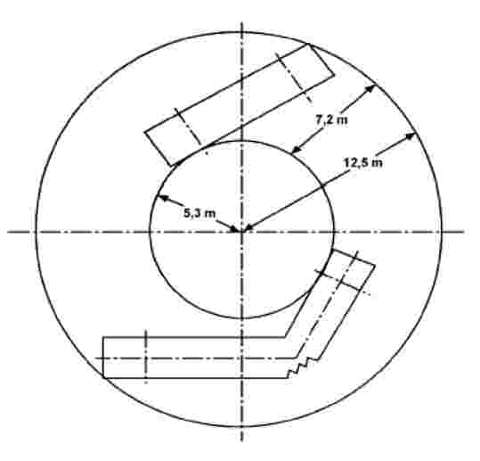
Figure B

Figure C

3.4.3. The requirements of paragraphs 3.4.1 and 3.4.2 may also be verified, at the request of the manufacturer, with an appropriate equivalent calculation or geometric demonstration.
3.4.4. In the case of incomplete vehicles, the manufacturer shall declare the maximum permissible dimensions for which the vehicle is to be checked against the requirements of paragraphs 3.4.1 and 3.4.2.
(1) Including 3 kg for hand baggage.
(2) This figure is reduced to 20 % for 3 axle vehicles of Classes II and III having two steered axles.
ANNEX 12
Additional safety prescriptions for trolleybuses
1. DEFINITIONS AND OPERATING PARAMETERS
For the purpose of this Annex:
1.1. ‘Line voltage’ means the voltage provided to the vehicle from the external power supply.
Trolleybuses shall be designed to operate at a rated line voltage of either:
|
(a) |
600 V (a working range of 400 to 720 V); or |
|
(b) |
750 V (a working range of 500 to 900 V). |
1.2. The electrical circuits of a trolleybus are classified as:
|
1.2.1. |
‘high voltage circuits’ means circuits energised at line voltage; |
|
1.2.2. |
‘low voltage circuits’ means circuits energised at a nominal voltage of 12 V, 24 V or 42 V. |
|
1.2.3. |
‘three phase circuits’ means circuits supplied with a three-phase voltage not exceeding 400 V AC. |
1.3. Rated climatic conditions
Trolleybuses shall be designed to operate reliably under the following environmental conditions:
|
1.3.1. |
a temperature range of minus – 40 °С to plus 40 °С; |
|
1.3.2. |
a relative humidity of 98 per cent at temperatures up to 25 °С; |
|
1.3.3. |
an atmospheric pressure range of 866 kPa to 1 066 kPa; |
|
1.3.4. |
an altitude range from sea level to a maximum of 1 000 m above the sea level. |
1.4. ‘Self-extinguishing material’ means a material that does not continue to burn when the ignition source is removed.
2. POWER COLLECTION
|
2.1. |
Electrical power shall be obtained from the contact wires by means of one or more power collection devices, normally comprising two trolley booms. (A single trolley boom or a pantograph may be used in guided applications). A trolley boom shall consist of a roof mounting (trolley base), a pole, an electrical power collector (trolley head) and a replaceable contact surface insert. Trolley booms shall be mounted so that they can turn in both horizontal and vertical directions. |
|
2.2. |
Poles shall be made of an insulated material or of metal covered with insulating material and shall be resistant to mechanical shocks. |
|
2.3. |
Power collectors shall be designed to maintain adequate positive contact with the contact wires when the wires are located at between 4 and 6 metres above the ground and, in the case of trolley booms, to allow the longitudinal axis of the trolleybus to deviate at least 4,0 metres to either side of the mean axis of the contact wires. |
|
2.4. |
If the power collector becomes accidentally detached from the contact wire (de-wired), the upper end of the power collector(s) shall not be raised higher than 7,2 metres above the road, or 1 metre maximum above the contact wires at the time of de-wiring, nor lower than 0,5 metres above the roof of the trolleybus. |
|
2.5. |
Each trolley boom shall be equipped with a device which retracts the boom automatically if the pole unwires. |
|
2.6. |
The trolley head, if dismounted from its normal position on the pole, shall be remain attached to the pole and must not fall down. |
|
2.7. |
The insulation resistance between the electric power collector and the roof mounting/trolley base shall be at least 10 МΩ: |
|
2.8. |
Power collectors may be equipped with remote control from the driver’s compartment, at least for retraction. |
|
2.9. |
Provision shall be made to enable the driver to replace, if necessary, contact surface inserts while the vehicle is in operation on the road. |
3. TRACTION AND AUXILIARY EQUIPMENT
|
3.1. |
Electrical components installed on the trolleybus shall be protected against over-voltage and short-circuit current. The protection shall preferably be assured by circuit breakers that are reset automatically, remotely or manually. |
|
3.2. |
Electrical components shall be protected against commutation or atmospheric over-voltage. |
|
3.3. |
Circuit breakers shall provide interruption of particular damaged circuits. |
|
3.4. |
If any circuit includes a single-pole circuit breaker, it shall be installed in the positive wire of the circuit. |
|
3.5. |
All electrical circuits and circuit branches shall be of dual wiring. The trolleybus body can be used for current earth return only for low voltage circuits. |
|
3.6. |
Battery cases, covers and trays shall be made of non-flammable or self-extinguishing materials. |
|
3.7. |
Electrical components energized at the line voltage shall have additional insulation from the vehicle. |
|
3.8. |
Electrical components, with the exception of traction resistors, shall be protected against penetration of moisture and dust into the body and onto insulated and current conducting parts. |
|
3.9. |
Within the rated climate conditions, with the trolleybus dry and clean, the insulation resistance of electrical circuits, when all rotating machines and apparatus are switched on, shall not be less than:
|
|
3.10. |
Wiring and apparatus:
|
|
3.11. |
Electrical machines, apparatus, devices and wiring shall withstand mechanical loads, applied to mounting points, as follows:
|
4. ELECTRICAL SAFETY OF PASSENGERS AND CREW
|
4.1. |
At the rated climate conditions, with the trolleybus dry and clean and connected to both positive and negative power supply via the power collection devices, the earth leakage current from the body shall not be higher than 0,2 mA. |
|
4.2. |
The trolleybus must be equipped with an onboard device for permanent monitoring of leakage current or voltage between the chassis and the road surface. The device shall disconnect the high voltage circuits from the contact system if the leakage current exceeds 3 mA at a line voltage of 600 V DC, or if the leakage voltage exceeds 40 V. |
|
4.3. |
Stanchions and handrails at doorways shall be made of insulating material or covered with mechanically durable insulation or insulated from the trolleybus body. The insulation resistance shall at least be 1,0 MΩ over a contact area of 100 ± 5 cm2. |
|
4.4. |
The first steps shall be made of insulating material or covered with mechanically durable insulation. The insulation resistance shall at least be 1,0 MΩ over a contact area of 300 ± 5 cm2. |
|
4.5. |
Door panels shall be made of insulating material or insulated from the trolleybus body. The insulation resistance shall be at least 1,0 MΩ over a contact area on the panel of 300 ± 5 cm2. |
|
4.6. |
The external body panels adjacent to the door apertures shall be covered with insulating material. The insulated area shall extend in width at least 50 cm each side of the door apertures and in height at least 200 cm from the roadway. The insulation resistance in respect to the trolleybus body shall not be less than 1,0 MΩ over a contact area of 200 ± 5 cm2. |
|
4.7. |
If the trolleybus is equipped with double-insulated converters, paragraphs 4.3 to 4.6 need not be applied. |
5. THE DRIVER’S COMPARTMENT
|
5.1. |
In the driver’s compartment, there should not be any high voltage equipment accessible by the driver. |
|
5.2. |
As a minimum, the instrument panel shall include:
|


