ISSN 1725-2555
doi:10.3000/17252555.L_2010.027.eng
Official Journal
of the European Union
L 27

English edition
Legislation
Volume 53
30 January 2010
|
ISSN 1725-2555 doi:10.3000/17252555.L_2010.027.eng |
||
|
Official Journal of the European Union |
L 27 |
|
|
|
||
|
English edition |
Legislation |
Volume 53 |
|
Contents |
|
IV Acts adopted before 1 December 2009 under the EC Treaty, the EU Treaty and the Euratom Treaty |
page |
|
|
* |
Regulation (EC) No 66/2010 of the European Parliament and of the Council of 25 November 2009 on the EU Ecolabel ( 1 ) |
|
|
|
* |
||
|
|
* |
Directive 2009/144/EC of the European Parliament and of the Council of 30 November 2009 on certain components and characteristics of wheeled agricultural or forestry tractors ( 1 ) |
|
|
|
|
|
(1) Text with EEA relevance |
|
EN |
Acts whose titles are printed in light type are those relating to day-to-day management of agricultural matters, and are generally valid for a limited period. The titles of all other Acts are printed in bold type and preceded by an asterisk. |
IV Acts adopted before 1 December 2009 under the EC Treaty, the EU Treaty and the Euratom Treaty
|
30.1.2010 |
EN |
Official Journal of the European Union |
L 27/1 |
REGULATION (EC) No 66/2010 OF THE EUROPEAN PARLIAMENT AND OF THE COUNCIL
of 25 November 2009
on the EU Ecolabel
(Text with EEA relevance)
THE EUROPEAN PARLIAMENT AND THE COUNCIL OF THE EUROPEAN UNION,
Having regard to the Treaty establishing the European Community, and in particular Article 175(1) thereof,
Having regard to the proposal from the Commission,
Having regard to the opinion of the European Economic and Social Committee (1),
Having regard to the opinion of the Committee of the Regions (2),
Acting in accordance with the procedure laid down in Article 251 of the Treaty (3),
Whereas:
|
(1) |
The aim of Regulation (EC) No 1980/2000 of the European Parliament and of the Council of 17 July 2000 on a revised Community eco-label award scheme (4) was to establish a voluntary ecolabel award scheme intended to promote products with a reduced environmental impact during their entire life cycle and to provide consumers with accurate, non-deceptive, science-based information on the environmental impact of products. |
|
(2) |
The experience gained during the implementation of Regulation (EC) No 1980/2000 has shown the need to amend that ecolabel scheme in order to increase its effectiveness and streamline its operation. |
|
(3) |
The amended scheme (hereinafter ‘the EU Ecolabel scheme’) should be implemented in compliance with the provisions of the Treaties, including, in particular, the precautionary principle as laid down in Article 174(2) of the EC Treaty. |
|
(4) |
It is necessary to ensure coordination between the EU Ecolabel scheme and the establishment of the requirements in the context of Directive 2009/125/EC of the European Parliament and of the Council of 21 October 2009 establishing a framework for the setting of ecodesign requirements for energy related products (5). |
|
(5) |
The EU Ecolabel scheme is part of the sustainable consumption and production policy of the Community, which aims at reducing the negative impact of consumption and production on the environment, health, climate and natural resources. The scheme is intended to promote those products which have a high level of environmental performance through the use of the EU Ecolabel. To this effect, it is appropriate to require that the criteria with which products must comply in order to bear the EU Ecolabel be based on the best environmental performance achieved by products on the Community market. Those criteria should be simple to understand and to use and should be based on scientific evidence, taking into consideration the latest technological developments. Those criteria should be market oriented and limited to the most significant environmental impacts of products during their whole life cycle. |
|
(6) |
In order to avoid the proliferation of environmental labelling schemes and to encourage higher environmental performance in all sectors for which environmental impact is a factor in consumer choice, the possibility of using the EU Ecolabel should be extended. However, for food and feed product groups, a study should be undertaken to ensure that criteria are feasible and that added value can be guaranteed. For food and feed products, as well as unprocessed agricultural products that lie within the scope of Council Regulation (EC) No 834/2007 of 28 June 2007 on organic production and labelling of organic products (6), the option that only those products certified as organic would be eligible for award of the EU Ecolabel should be considered, to avoid confusion for consumers. |
|
(7) |
The EU Ecolabel should aim at substituting hazardous substances by safer substances, wherever technically possible. |
|
(8) |
For the acceptance by the general public of the EU Ecolabel scheme, it is essential that environmental non-governmental organisations (NGOs) and consumer organisations play an important role and be actively involved in the development and setting of EU Ecolabel criteria. |
|
(9) |
It is desirable that any interested party may lead the development or revision of EU Ecolabel criteria provided that common procedural rules are followed and that the process is coordinated by the Commission. In order to ensure the overall coherence of the Community's action, it is also appropriate to require that the latest strategic objectives of the Community in the field of the environment, such as Environment Action Programmes, Sustainable Development Strategies and Climate Change Programmes, be taken into account in the development or revision of EU Ecolabel criteria. |
|
(10) |
In order to simplify the EU Ecolabel scheme and to reduce the administrative burden associated with the use of the EU Ecolabel, the assessment and verification procedures should be streamlined. |
|
(11) |
It is appropriate to provide for the conditions under which the EU Ecolabel may be used and, in order to ensure compliance with those conditions, to require competent bodies to undertake verifications and to prohibit the use of the EU Ecolabel where the conditions for use have not been complied with. It is also appropriate to require Member States to lay down the rules on penalties applicable to infringements of this Regulation and to ensure that they are implemented. |
|
(12) |
In order to increase the use of the EU Ecolabel and in order to encourage those whose products meet the EU Ecolabel criteria, the costs of using the EU Ecolabel should be reduced. |
|
(13) |
It is necessary to inform the public and to raise public awareness of the EU Ecolabel through promotion actions, information and education campaigns, at local, national and Community levels, in order to make consumers aware of the meaning of the EU Ecolabel and to enable them to make informed choices. It is also necessary in order to make the scheme more attractive to producers and retailers. |
|
(14) |
Member States should consider guidelines when they establish their national Green Public Procurement Action Plans and could consider the setting of targets for public purchasing of environmental friendly products. |
|
(15) |
In order to facilitate the marketing of products bearing environmental labels at national and Community levels, to limit additional work for companies, in particular SMEs, and to avoid confusing consumers, it is also necessary to enhance the coherence and promote harmonisation between the EU Ecolabel scheme and national ecolabelling schemes in the Community. |
|
(16) |
In order to ensure a harmonised application of the awarding system and of the market surveillance and control of the use of the EU Ecolabel throughout the Community, competent bodies should exchange information and experiences. |
|
(17) |
The measures necessary for the implementation of this Regulation should be adopted in accordance with Council Decision 1999/468/EC of 28 June 1999 laying down the procedures for the exercise of implementing powers conferred on the Commission (7). |
|
(18) |
In particular, the Commission should be empowered to adopt the criteria with which products must comply in order to bear the EU Ecolabel and to amend the Annexes to this Regulation. Since those measures are of general scope and are designed to amend non-essential elements of this Regulation, inter alia by supplementing it with new non-essential elements, they must be adopted in accordance with the regulatory procedure with scrutiny provided for in Article 5a of Decision 1999/468/EC. |
|
(19) |
For reasons of clarity and legal certainty, Regulation (EC) No 1980/2000 should therefore be replaced by this Regulation. |
|
(20) |
Appropriate transitional provisions should be provided to ensure a smooth transition between Regulation (EC) No 1980/2000 and this Regulation, |
HAVE ADOPTED THIS REGULATION:
Article 1
Subject matter
This Regulation lays down rules for the establishment and application of the voluntary EU Ecolabel scheme.
Article 2
Scope
1. This Regulation shall apply to any goods or services which are supplied for distribution, consumption or use on the Community market whether in return for payment or free of charge (hereinafter ‘products’).
2. This Regulation shall apply neither to medicinal products for human use, as defined in Directive 2001/83/EC of the European Parliament and of the Council of 6 November 2001 on the Community code relating to medicinal products for human use (8), or for veterinary use, as defined in Directive 2001/82/EC of the European Parliament and of the Council of 6 November 2001 on the Community code relating to veterinary medicinal products (9), nor to any type of medical device.
Article 3
Definitions
For the purposes of this Regulation, the following definitions shall apply:
|
1. |
‘product group’ means a set of products that serve similar purposes and are similar in terms of use, or have similar functional properties, and are similar in terms of consumer perception; |
|
2. |
‘operator’ means any producer, manufacturer, importer, service provider, wholesaler or retailer; |
|
3. |
‘environmental impact’ means any change to the environment resulting wholly or partially from a product during its life cycle; |
|
4. |
‘environmental performance’ means the result of a manufacturer's management of those characteristics of a product that cause environmental impact; |
|
5. |
‘verification’ means a procedure to certify that a product complies with specified EU Ecolabel criteria. |
Article 4
Competent bodies
1. Each Member State shall designate the body or bodies, within government ministries or outside, responsible for carrying out the tasks provided for in this Regulation (‘the competent body’ or ‘the competent bodies’) and ensure that they are operational. Where more than one competent body is designated, the Member State shall determine those bodies’ respective powers and the coordination requirements applicable to them.
2. The composition of the competent bodies shall be such as to guarantee their independence and neutrality and their rules of procedure shall be such as to ensure transparency in the conduct of their activities as well as the involvement of all interested parties.
3. Member States shall ensure that competent bodies meet the requirements laid down in Annex V.
4. Competent bodies shall ensure that the verification process is carried out in a consistent, neutral and reliable manner by a party independent from the operator being verified, based on international, European or national standards and procedures concerning bodies operating product-certification schemes.
Article 5
European Union Ecolabelling Board
1. The Commission shall establish a European Union Ecolabelling Board (EUEB) consisting of the representatives of the competent bodies of all the Member States, as referred to in Article 4, and of other interested parties. The EUEB shall elect its president according to its rules of procedure. It shall contribute to the development and revision of EU Ecolabel criteria and to any review of the implementation of the EU Ecolabel scheme. It shall also provide the Commission with advice and assistance in these areas and, in particular, issue recommendations on minimum environmental performance requirements.
2. The Commission shall ensure that, in the conduct of its activities, the EUEB observes a balanced participation of all relevant interested parties in respect of each product group, such as competent bodies, producers, manufacturers, importers, service providers, wholesalers, retailers, notably SMEs, and environmental protection groups and consumer organisations.
Article 6
General requirements for EU Ecolabel criteria
1. EU Ecolabel criteria shall be based on the environmental performance of products, taking into account the latest strategic objectives of the Community in the field of the environment.
2. EU Ecolabel criteria shall set out the environmental requirements that a product must fulfil in order to bear the EU Ecolabel.
3. EU Ecolabel criteria shall be determined on a scientific basis considering the whole life cycle of products. In determining such criteria, the following shall be considered:
|
(a) |
the most significant environmental impacts, in particular the impact on climate change, the impact on nature and biodiversity, energy and resource consumption, generation of waste, emissions to all environmental media, pollution through physical effects and use and release of hazardous substances; |
|
(b) |
the substitution of hazardous substances by safer substances, as such or via the use of alternative materials or designs, wherever it is technically feasible; |
|
(c) |
the potential to reduce environmental impacts due to durability and reusability of products; |
|
(d) |
the net environmental balance between the environmental benefits and burdens, including health and safety aspects, at the various life stages of the products; |
|
(e) |
where appropriate, social and ethical aspects, e.g. by making reference to related international conventions and agreements such as relevant ILO standards and codes of conduct; |
|
(f) |
criteria established for other environmental labels, particularly officially recognised, nationally or regionally, EN ISO 14024 type I environmental labels, where they exist for that product group so as to enhance synergies; |
|
(g) |
as far as possible the principle of reducing animal testing. |
4. EU Ecolabel criteria shall include requirements intended to ensure that the products bearing the EU Ecolabel function adequately in accordance with their intended use.
5. Before developing EU Ecolabel criteria for food and feed products, as defined in Regulation (EC) No 178/2002 of the European Parliament and of the Council of 28 January 2002 laying down the general principles and requirements of food law, establishing the European Food Safety Authority and laying down procedures in matters of food safety (10), the Commission shall undertake a study, by 31 December 2011 at the latest, exploring the feasibility of establishing reliable criteria covering environmental performance during the whole life cycle of such products, including the products of fishing and aquaculture. The study should pay particular attention to the impact of any EU Ecolabel criteria on food and feed products, as well as unprocessed agricultural products that lie within the scope of Regulation (EC) No 834/2007. The study should consider the option that only those products certified as organic would be eligible for award of the EU Ecolabel, to avoid confusion for consumers.
The Commission shall decide, taking into account the outcome of the study and the opinion of the EUEB, for which group of food and feed, if any, the development of EU Ecolabel criteria is feasible, in accordance with the regulatory procedure with scrutiny referred to in Article 16(2).
6. The EU Ecolabel may not be awarded to goods containing substances or preparations/mixtures meeting the criteria for classification as toxic, hazardous to the environment, carcinogenic, mutagenic or toxic for reproduction (CMR), in accordance with Regulation (EC) No 1272/2008 of the European Parliament and of the Council of 16 December 2008 on classification, labelling and packaging of substances and mixtures (11), nor to goods containing substances referred to in Article 57 of Regulation (EC) No 1907/2006 of the European Parliament and of the Council of 18 December 2006 concerning the Registration, Evaluation, Authorisation and Restriction of Chemicals (REACH), establishing a European Chemicals Agency (12).
7. For specific categories of goods containing substances referred to in paragraph 6, and only in the event that it is not technically feasible to substitute them as such, or via the use of alternative materials or designs, or in the case of products which have a significantly higher overall environment performance compared with other goods of the same category, the Commission may adopt measures to grant derogations from paragraph 6. No derogation shall be given concerning substances that meet the criteria of Article 57 of Regulation (EC) No 1907/2006 and that are identified according to the procedure described in Article 59(1) of that Regulation, present in mixtures, in an article or in any homogeneous part of a complex article in concentrations higher than 0,1 % (weight by weight). Those measures, designed to amend non-essential elements of this Regulation, shall be adopted in accordance with the regulatory procedure with scrutiny referred to in Article 16(2).
Article 7
Development and revision of EU Ecolabel criteria
1. Following consultation of the EUEB, the Commission, Member States, competent bodies and other stakeholders may initiate and lead the development or revision of EU Ecolabel criteria. Where such other stakeholders are put in charge of leading the development of criteria, they must demonstrate expertise in the product area, as well as the ability to lead the process with neutrality and in line with the aims of this Regulation. In this regard, consortiums consisting of more than one interest group shall be favoured.
The party which initiates and leads the development or revision of EU Ecolabel criteria shall, in accordance with the procedure set out in Part A of Annex I, produce the following documents:
|
(a) |
a preliminary report; |
|
(b) |
a proposal for draft criteria; |
|
(c) |
a technical report in support of the proposal for draft criteria; |
|
(d) |
a final report; |
|
(e) |
a manual for potential users of the EU Ecolabel and competent bodies; |
|
(f) |
a manual for authorities awarding public contracts. |
Those documents shall be submitted to the Commission and to the EUEB.
2. Where criteria have already been developed under another ecolabel scheme complying with the requirements of EN ISO 14024 type I environmental labels for a product group for which no EU Ecolabel criteria have been established, any Member State in which the other ecolabel scheme is recognised may, after consulting the Commission and the EUEB, propose those criteria for development under the EU Ecolabel scheme.
In such cases, the shortened criteria development procedure laid down in Part B of Annex I may apply provided that the proposed criteria have been developed in line with Part A of Annex I. Either the Commission or the Member State which, according to the first subparagraph, has proposed the shortened criteria development procedure shall lead that procedure.
3. Where a non-substantial revision of the criteria is necessary, the shortened revision procedure laid down in Part C of Annex I may apply.
4. By 19 February 2011, the EUEB and the Commission shall agree on a working plan including a strategy and a non-exhaustive list of product groups. This plan will consider other Community action (e.g. in the field of green public procurement) and may be updated according to the latest strategic objectives of the Community in the field of the environment. This plan shall be regularly updated.
Article 8
Establishment of EU Ecolabel criteria
1. Draft EU Ecolabel criteria shall be developed in accordance with the procedure laid down in Annex I and taking into account the working plan.
2. The Commission shall, no later than nine months after consulting the EUEB, adopt measures to establish specific EU Ecolabel criteria for each product group. These measures shall be published in the Official Journal of the European Union.
In its final proposal, the Commission shall take into account the comments of the EUEB and shall clearly highlight, document and provide explanations for the reasoning behind any changes in its final proposal compared to the proposal for draft criteria following the consultation of the EUEB.
Those measures, designed to amend non-essential elements of this Regulation, by supplementing it, shall be adopted in accordance with the regulatory procedure with scrutiny referred to in Article 16(2).
3. In the measures referred to in paragraph 2 the Commission shall:
|
(a) |
establish requirements for assessing the compliance of specific products with EU Ecolabel criteria (‘assessment requirements’); |
|
(b) |
specify, for each product group, three key environmental characteristics that may be displayed in the optional label with text box described in Annex II; |
|
(c) |
specify, for each product group, the relevant period of validity of the criteria and of the assessment requirements; |
|
(d) |
specify the degree of product variability allowed during the period of validity referred to in point (c). |
4. When establishing EU Ecolabel criteria, care shall be taken not to introduce measures whose implementation may impose disproportionate administrative and economic burdens on SMEs.
Article 9
Award of the EU Ecolabel and terms and conditions of its use
1. Any operator who wishes to use the EU Ecolabel shall apply to the competent bodies referred to in Article 4 in accordance with the following rules:
|
(a) |
where a product originates in a single Member State, the application shall be presented to a competent body of that Member State; |
|
(b) |
where a product originates in the same form in several Member States, the application may be presented to a competent body in one of those Member States; |
|
(c) |
where a product originates outside the Community, the application shall be presented to a competent body in any of the Member States in which the product is to be or has been placed on the market. |
2. The EU Ecolabel shall have the form depicted in Annex II.
The EU Ecolabel may only be used in connection with products complying with the EU Ecolabel criteria applicable to the products concerned and for which the EU Ecolabel has been awarded.
3. Applications shall specify the full contact details of the operator, as well as the product group in question and shall contain a full description of the product as well as all other information requested by the competent body.
Applications shall include all relevant documentation, as specified in the relevant Commission measure establishing EU Ecolabel criteria for the product group in question.
4. The competent body to which an application is made shall charge fees according to Annex III. The use of the EU Ecolabel shall be conditional upon the fees having been paid in due time.
5. Within two months of receipt of an application, the competent body concerned shall check whether the documentation is complete and shall notify the operator. The competent body may reject the application if the operator fails to complete the documentation within six months after such notification.
Provided that the documentation is complete and the competent body has verified that the product complies with the EU Ecolabel criteria and assessment requirements published according to Article 8, the competent body shall assign a registration number to the product.
Operators shall meet the costs of testing and assessment of conformity with EU Ecolabel criteria. Operators may be charged for travel and accommodation costs where an on-site verification is needed outside the Member State in which the competent body is based.
6. Where EU Ecolabel criteria require production facilities to meet certain requirements, they shall be met in all facilities in which the product bearing the EU Ecolabel is manufactured. Where appropriate, the competent body shall undertake on-site verifications or assign an authorised agent for that purpose.
7. Competent bodies shall preferentially recognise tests which are accredited according to ISO 17025 and verifications performed by bodies which are accredited under the EN 45011 standard or an equivalent international standard. Competent bodies shall collaborate in order to ensure the effective and consistent implementation of the assessment and verification procedures, notably through the working group referred to in Article 13.
8. The competent body shall conclude a contract with each operator, covering the terms of use of the EU Ecolabel (including provisions for the authorisation and withdrawal of the EU Ecolabel, notably following the revision of criteria). To that end a standard contract shall be used in accordance with the template in Annex IV.
9. The operator may place the EU Ecolabel on the product only after conclusion of the contract. The operator shall also place the registration number on the product bearing the EU Ecolabel.
10. The competent body which has awarded the EU Ecolabel to a product shall notify the Commission thereof. The Commission shall establish a common register and update it regularly. That register shall be publicly available on a website dedicated to the EU Ecolabel.
11. The EU Ecolabel may be used on the products for which the EU Ecolabel has been awarded and on their associated promotional material.
12. The award of the EU Ecolabel shall be without prejudice to environmental or other regulatory requirements of Community or national law applicable to the various life stages of the product.
13. The right to use the EU Ecolabel shall not extend to the use of the EU Ecolabel as a component of a trademark.
Article 10
Market surveillance and control of the use of the EU Ecolabel
1. Any false or misleading advertising or use of any label or logo which leads to confusion with the EU Ecolabel shall be prohibited.
2. The competent body shall, in respect of products to which it has awarded the EU Ecolabel, verify that the product complies with the EU Ecolabel criteria and assessment requirements published under Article 8, on a regular basis. The competent body shall, as appropriate, also undertake such verifications upon complaint. These verifications may take the form of random spot-checks.
The competent body which has awarded the EU Ecolabel to the product shall inform the user of the EU Ecolabel of any complaints made concerning the product bearing the EU Ecolabel, and may request the user to reply to those complaints. The competent body may withhold the identity of the complainant from the user.
3. The user of the EU Ecolabel shall allow the competent body which has awarded the EU Ecolabel to the product to undertake all necessary investigations to monitor its on-going compliance with the product group criteria and Article 9.
4. The user of the EU Ecolabel shall, upon request by the competent body which has awarded the EU Ecolabel to the product, grant access to the premises on which the product concerned is produced.
The request may be made at any reasonable time and without notice.
5. Where, after giving the user of the EU Ecolabel the opportunity to submit observations, any competent body which finds that a product bearing the EU Ecolabel does not comply with the relevant product group criteria or that the EU Ecolabel is not used in accordance with Article 9, it shall either prohibit the use of the EU Ecolabel on that product, or, in the event that the EU Ecolabel has been awarded by another competent body, it shall inform that competent body. The user of the EU Ecolabel shall not be entitled to repayment of the fees referred to in Article 9(4), either in whole or in part.
The competent body shall without delay inform all other competent bodies and the Commission of that prohibition.
6. The competent body which has awarded the EU Ecolabel to the product shall not disclose, or use for any purpose unconnected with the award for use of the EU Ecolabel, information to which it has gained access in the course of assessing the compliance by a user of the EU Ecolabel with the rules on use of the EU Ecolabel set out in Article 9.
It shall take all reasonable steps to secure the protection of the documents provided to it against falsification and misappropriation.
Article 11
Ecolabelling schemes in the Member States
1. Where EU Ecolabel criteria for a given product group have been published, other nationally or regionally officially recognised EN ISO 14024 type I ecolabelling schemes which do not cover that product group at the time of publication may be extended to that product group only where the criteria developed under those schemes are at least as strict as the EU Ecolabel criteria.
2. In order to harmonise the criteria of European ecolabelling schemes (EN ISO 14024 type I), EU Ecolabel criteria shall also take into account existing criteria developed in officially recognised ecolabelling schemes in the Member States.
Article 12
Promotion of the EU Ecolabel
1. Member States and the Commission shall, in cooperation with the EUEB, agree on a specific action plan to promote the use of the EU Ecolabel by:
|
(a) |
awareness-raising actions and information and public education campaigns for consumers, producers, manufacturers, wholesalers, service providers, public purchasers, traders, retailers and the general public, |
|
(b) |
encouraging the uptake of the scheme, especially for SMEs, |
thus supporting the development of the scheme.
2. Promotion of the EU Ecolabel may be undertaken via the EU Ecolabel website providing basic information and promotional materials on the EU Ecolabel, and information on where to purchase EU Ecolabel products, in all Community languages.
3. Member States shall encourage the use of the ‘Manual for authorities awarding public contracts’, as specified in Annex I, Part A, point 5. For this purpose, Member States shall consider, for example, the setting of targets for the purchasing of products meeting the criteria specified in that Manual.
Article 13
Exchange of information and experiences
1. In order to foster consistent implementation of this Regulation, competent bodies shall regularly exchange information and experiences, in particular on the application of Articles 9 and 10.
2. The Commission shall set up a working group of competent bodies for this purpose. The working group shall meet at least twice a year. Travel expenses shall be borne by the Commission. The working group shall elect its chair and adopt its rules of procedure.
Article 14
Report
By 19 February 2015, the Commission shall submit to the European Parliament and the Council a report on the implementation of the EU Ecolabel scheme. The report shall also identify elements for a possible review of the scheme.
Article 15
Amendment of Annexes
The Commission may amend the Annexes, including modifying the maximum fees provided for in Annex III taking into account the need for fees to cover the costs of running the scheme.
Those measures, designed to amend non-essential elements of this Regulation, shall be adopted in accordance with the regulatory procedure with scrutiny referred to in Article 16(2).
Article 16
Committee procedure
1. The Commission shall be assisted by a Committee.
2. Where reference is made to this paragraph, Article 5a(1) to (4) and Article 7 of Decision 1999/468/EC shall apply, having regard to the provisions of Article 8 thereof.
Article 17
Penalties
Member States shall lay down the rules on penalties applicable to infringements of the provisions of this Regulation and shall take all measures necessary to ensure that they are implemented. The penalties provided for must be effective, proportionate and dissuasive. The Member States shall notify those provisions to the Commission without delay and shall notify it without delay of any subsequent amendment affecting them.
Article 18
Repeal
Regulation (EC) No 1980/2000 is hereby repealed.
Article 19
Transitional provisions
Regulation (EC) No 1980/2000 shall continue to apply to contracts concluded under Article 9 thereof until the date of expiry specified in those contracts, except for its provisions concerning fees.
Article 9(4) of and Annex III to this Regulation shall apply to such contracts.
Article 20
Entry into force
This Regulation shall enter into force on the twentieth day following its publication in the Official Journal of the European Union.
This Regulation shall be binding in its entirety and directly applicable in all Member States.
Done at Strasbourg, 25 November 2009.
For the European Parliament
The President
J. BUZEK
For the Council
The President
Å. TORSTENSSON
(1) OJ C 120, 28.5.2009, p. 56.
(2) OJ C 218, 11.9.2009, p. 50.
(3) Opinion of the European Parliament of 2 April 2009 (not yet published in the Official Journal) and Council Decision of 26 October 2009.
(4) OJ L 237, 21.9.2000, p. 1.
(5) OJ L 285, 31.10.2009, p. 10.
(6) OJ L 189, 20.7.2007, p. 1.
(7) OJ L 184, 17.7.1999, p. 23.
(8) OJ L 311, 28.11.2001, p. 67.
(9) OJ L 311, 28.11.2001, p. 1.
(11) OJ L 353, 31.12.2008, p. 1.
(12) OJ L 396, 30.12.2006, p. 1.
ANNEX I
PROCEDURE FOR THE DEVELOPMENT AND REVISION OF EU ECOLABEL CRITERIA
A. Standard procedure
The following documents must be drawn up:
1. Preliminary report
The preliminary report must contain the following elements:
|
— |
Quantitative indication of the potential environmental benefits related to the product group, including consideration of the benefits from other similar European and national or regional EN ISO 14024 type I ecolabelling schemes, |
|
— |
Reasoning for choice and scope of product group, |
|
— |
Consideration of any possible trade issues, |
|
— |
Analysis of other environmental labels' criteria, |
|
— |
Current laws and ongoing legislative initiatives related to the product group sector, |
|
— |
Analysis of the possibilities of substitution of hazardous substances by safer substances, as such or via the use of alternative materials or designs, wherever technically feasible, in particular with regard to substances of very high concern as referred to in Article 57 of Regulation (EC) No 1907/2006, |
|
— |
Intra-community market data for the sector, including volumes and turnover, |
|
— |
Current and future potential for market penetration of the products bearing the EU Ecolabel, |
|
— |
Extent and overall relevance of the environmental impacts associated with the product group, based on new or existing life cycle assessment studies. Other scientific evidence may also be used. Critical and controversial issues shall be reported in detail and evaluated, |
|
— |
References of data and information collected and used for issuing the report. |
The preliminary report shall be made available on the Commission's dedicated EU Ecolabel website for comment and reference during the development of the criteria.
Where criteria are to be developed for food and feed product groups, the preliminary report must, with reference to the study undertaken according to Article 6(5), demonstrate the following:
|
— |
there is a real added environmental value in developing EU Ecolabel criteria for the chosen product, |
|
— |
the EU Ecolabel has considered the whole life cycle of the product, and |
|
— |
the use of the EU Ecolabel on the chosen product will not cause confusion when compared with other food labels. |
2. Proposal for draft criteria and associated technical report
Following the publication of the preliminary report, a proposal for draft criteria and a technical report in support of the proposal shall be established.
The draft criteria shall comply with the following requirements:
|
— |
they shall be based on the best products available on the Community market in terms of environmental performance throughout the life cycle, and they shall correspond indicatively to the best 10-20 % of the products available on the Community market in terms of environmental performance at the moment of their adoption, |
|
— |
in order to allow for the necessary flexibility the exact percentage shall be defined on a case-by-case basis and in each case with the aim of promoting the most environmentally friendly products and ensuring that consumers are provided with sufficient choice, |
|
— |
they shall take into consideration the net environmental balance between the environmental benefits and burdens, including health and safety aspects; where appropriate, social and ethical aspects shall be considered, e.g. by making reference to related international conventions and agreements such as relevant ILO standards and codes of conduct, |
|
— |
they shall be based on the most significant environmental impacts of the product, be expressed as far as reasonably possible via technical key environmental performance indicators of the product, and be suitable for assessment according to the rules of this Regulation, |
|
— |
they shall be based on sound data and information which are representative as far as possible of the entire Community market, |
|
— |
they shall be based on life cycle data and quantitative environmental impacts, where applicable in compliance with the European Reference Life Cycle Data Systems (ELCD), |
|
— |
they shall take into consideration the views of all interested parties involved in the consultation process, |
|
— |
they shall guarantee harmonisation with existing legislation applicable to the product group when considering definitions, test methods and technical and administrative documentation, |
|
— |
they shall take into account relevant Community policies and work done on other related product groups. |
The proposal for draft criteria shall be written in a way that is easily accessible to those wishing to use them. It shall provide justification for each criterion and explain the environmental benefits related to each criterion. It shall highlight the criteria corresponding to the key environmental characteristics.
The technical report shall include at least the following elements:
|
— |
the scientific explanations of each requirement and criterion, |
|
— |
a quantitative indication of the overall environmental performance that the criteria are expected to achieve in their totality, when compared to that of the average products on the market, |
|
— |
an estimation of the expected environmental/economic/social impacts of the criteria as a whole, |
|
— |
the relevant test methods for assessment of the different criteria, |
|
— |
an estimation of testing costs, |
|
— |
for each criterion, information about all tests, reports and other documentation that shall be produced by users on request from a competent body in accordance with Article 10(3). |
The proposal for draft criteria and the technical report shall be made available for public consultation on the Commission's dedicated EU Ecolabel website for comment. The party leading the product group development shall distribute the proposal and the report to all interested parties.
At least two open working group meetings shall be held on the draft criteria, to which all interested parties, such as competent bodies, industry (including SMEs), trade unions, retailers, importers, environmental and consumer organisations, shall be invited. The Commission shall also participate in those meetings.
The proposal for draft criteria and the technical report shall be made available at least one month before the first working group meeting. Any subsequent proposal for draft criteria shall be made available at least one month before subsequent meetings. The reasoning behind any changes to the criteria in subsequent drafts shall be fully explained and documented with reference to discussions in the open working groups meetings and comments received in public consultation.
Responses shall be given to all comments received during the criteria development process, indicating whether they are accepted or rejected and why.
3. Final report and draft criteria
The final report shall contain the following elements:
Clear responses to all comments and proposals, indicating whether they are accepted or rejected and why. European Union and non-European Union interested parties shall be treated on an equal footing.
It shall also include the following elements:
|
— |
a one-page summary of the level of support for the draft criteria by the competent bodies, |
|
— |
a summary list of all documents circulated in the course of the criteria development work, together with an indication of the date of circulation of each document and to whom each document has been circulated, and a copy of the documents in question, |
|
— |
a list of the interested parties involved in the work or which have been consulted or have expressed an opinion, together with their contact information, |
|
— |
an executive summary, |
|
— |
three key environmental characteristics for the product group that may be displayed in the optional label with text box described in Annex II, |
|
— |
a proposal for a marketing and communication strategy for the product group. |
Any observations received on the final report shall be taken into consideration, and information on the follow-up to the comments shall be provided on request.
4. Manual for potential users of the EU Ecolabel and competent bodies
A manual shall be established in order to assist potential users of the EU Ecolabel and competent bodies in assessing the compliance of products with the criteria.
5. Manual for authorities awarding public contracts
A manual providing guidance for the use of EU Ecolabel criteria to authorities awarding public contracts shall be established.
The Commission will provide templates translated into all official Community languages for the manual for potential users and competent bodies and for the manual for authorities awarding public contracts.
B. Shortened procedure where criteria have been developed by other EN ISO 14024 type I ecolabelling schemes
A single report shall be submitted to the Commission. This report shall include a section demonstrating that the technical and consultation requirements set out in Part A have been met, along with a proposal for draft criteria, a manual for potential users of the EU Ecolabel and competent bodies, and a manual for authorities awarding public contracts.
If the Commission is satisfied that the report and criteria meet the requirements set out in Part A, the report and the proposal for draft criteria shall be made available for public consultation on the Commission's dedicated EU Ecolabel website for a period of two months for comment.
Responses shall be given to all comments received during the public consultation period, indicating whether each comment is accepted or rejected and why.
Subject to any changes made during the public consultation period, and if no Member State requests an open working group meeting, the Commission may adopt the criteria pursuant to Article 8.
Upon request from any Member State, an open working group meeting shall be held on the draft criteria, in which all interested parties, such as competent bodies, industry (including SMEs), trade unions, retailers, importers, environmental and consumer organisations, shall participate. The Commission shall also participate in that meeting.
Subject to any changes made during the public consultation period or during the working group meeting, the Commission may adopt the criteria pursuant to Article 8.
C. Shortened procedure for non-substantial revision of the criteria
The Commission shall produce a report containing the following:
|
— |
a justification explaining why there is no need for a full revision of the criteria and why a simple updating of the criteria and their stringency levels is sufficient, |
|
— |
a technical section updating the previous market data used for the setting of the criteria, |
|
— |
a proposal for draft revised criteria, |
|
— |
a quantitative indication of the overall environmental performance that the revised criteria are expected to achieve in their totality, when compared to that of the average products on the market, |
|
— |
a revised manual for potential users of the EU Ecolabel and competent bodies, and |
|
— |
a revised manual for authorities awarding public contracts. |
The report and the proposal for draft criteria shall be made available for public consultation on the Commission's dedicated EU Ecolabel website for a period of two months for comment.
Responses shall be given to all comments received during the public consultation period, indicating whether each comment is accepted or rejected and why.
Subject to any changes made during the public consultation period, and if no Member State requests an open working group meeting, the Commission may adopt the criteria pursuant to Article 8.
Upon request from any Member State, an open working group meeting shall be held on the draft revised criteria, in which all interested parties, such as competent bodies, industry (including SMEs), trade unions, retailers, importers, environmental and consumer organisations, shall participate. The Commission shall also participate in that meeting.
Subject to any changes made during the public consultation period or during the working group meeting, the Commission may adopt the criteria pursuant to Article 8.
ANNEX II
FORM OF THE EU ECOLABEL
The EU Ecolabel shall take the following form:
Label:

Optional label with text box (the possibility for the operator to use this text box and the text used shall be that specified in the relevant product group criteria):

The EU Ecolabel registration number shall also appear on the product. It shall take the following form:
![]()
Where xxxx refers to the country of registration, yyy refers to the product group and zzzzz refers to the number given by the competent body.
The label, the optional label with text box and the registration number shall be printed either in two colours (Pantone 347 green for the leaves and stem of the flower, the ‘Є’ symbol, the web address and the EU acronym and Pantone 279 for all other elements, text and borders), or in black on white, or in white on black.
ANNEX III
FEES
1. Application fee
The competent body to which an application is made shall charge a fee according to the real administrative costs of processing the application. This fee shall be no lower than EUR 200 and no higher than EUR 1 200.
In the case of small and medium enterprises (1) and operators in developing countries, the maximum application fee shall be no higher than EUR 600.
In the case of micro-enterprises (1) the maximum application fee shall be EUR 350.
The application fee shall be reduced by 20 % for applicants registered under the Community eco-management and audit scheme (EMAS) and/or certified under the standard ISO 14001. This reduction is subject to the condition that the applicant explicitly commits, in its environmental policy, to ensure full compliance of its ecolabelled products with the EU Ecolabel criteria throughout the period of validity of the contract and that this commitment is appropriately incorporated into the detailed environmental objectives. ISO 14001 certified applicants shall demonstrate annually the implementation of this commitment. EMAS registered applicants shall forward a copy of their annually verified environmental statement.
2. Annual fee
The competent body may require each applicant who has been awarded an EU Ecolabel to pay an annual fee of up to EUR 1 500 for the use of the label.
In the case of small and medium enterprises and operators in developing countries, the maximum annual fee shall be no higher than EUR 750.
In the case of micro-enterprises the maximum annual fee shall be EUR 350.
The period covered by the annual fee will begin with the date of the award of the EU Ecolabel to the applicant.
(1) SMEs and micro-enterprises as defined by Commission Recommendation 2003/361/EC of 6 May 2003 (OJ L 124, 20.5.2003, p. 36).
ANNEX IV
STANDARD CONTRACT COVERING THE TERMS OF USE OF THE EU ECOLABEL
PREAMBLE
The competent body … (full title) hereinafter called ‘the competent body’,
registered at … (full address), which for the purposes of the signature of this contract is represented by … (name of person responsible), … (full name of holder), in his capacity as producer, manufacturer, importer, service provider, wholesaler or retailer whose official registered address is … (full address), hereafter called ‘the holder’, represented by … (name of person responsible), have agreed the following with regard to the use of the EU Ecolabel, pursuant to Regulation (EC) No 66/2010 of the European Parliament and of the Council of 25 November 2009 on the EU Ecolabel (1), hereinafter ‘the EU Ecolabel Regulation’:
1. USE OF THE EU ECOLABEL
1.1. The competent body grants the holder the right to use the EU Ecolabel for his products as described in the annexed product specifications, which conform to the relevant product group criteria in force for the period …, adopted by the Commission of the European Communities on … (date), published in the Official Journal of the European Union of … (full reference), and annexed to this contract.
1.2. The EU Ecolabel shall be used only in the forms stipulated in Annex II to the EU Ecolabel Regulation.
1.3. The holder shall ensure that the product to be labelled complies throughout the duration of this contract with all the terms of use and provisions set out in Article 9 of the EU Ecolabel Regulation, at all times. No new application will be required for modifications in the characteristics of the products which do not affect compliance with the criteria. The holder shall however inform the competent body of such modifications by registered letter. The competent body may carry out appropriate verifications.
1.4. The contract may be extended to a wider range of products than those initially foreseen, subject to agreement by the competent body, and subject to the condition that they belong to the same product group and that they also comply with its criteria. The competent body may verify that these conditions are met. The Annex detailing the product specifications shall be modified accordingly.
1.5. The holder shall not advertise or make any statement or use any label or logo in a way which is false or misleading or which results in confusion with, or calls into question the integrity of, the EU Ecolabel.
1.6. The holder shall be responsible under this contract for the manner in which the EU Ecolabel is used in relation to his product, especially in the context of advertising.
1.7. The competent body, including its agents authorised for such purpose, may undertake all necessary investigations to monitor the ongoing compliance by the holder with both the product group criteria and the terms of use and provisions of this contract in accordance with the rules laid down in Article 10 of the EU Ecolabel Regulation.
2. SUSPENSION AND WITHDRAWAL
2.1. In the event that the holder becomes aware that he is failing to meet the terms of use or provisions contained in Article 1 of this contract, the holder shall notify the competent body and refrain from using the EU Ecolabel until those terms for use or provisions have been fulfilled and the competent body has been notified thereof.
2.2. Where the competent body considers that the holder has contravened any of the terms of use or provisions of this contract, the competent body shall be entitled to suspend or withdraw its authorisation to the holder to use the EU Ecolabel, and to take such measures as are necessary to prevent the holder from using it further, including such measures as are provided for in Articles 10 and 17 of the EU Ecolabel Regulation.
3. LIMITATION OF LIABILITY AND INDEMNITY
3.1. The holder shall not include the EU Ecolabel as part of any guarantee or warranty in relation to the product referred to in Article 1.1 of this contract.
3.2. The competent body, including its authorised agents, shall not be liable for any loss or damage sustained by the holder arising out of the award and/or use of the EU Ecolabel.
3.3. The competent body, including its authorised agents, shall not be liable for any loss or damage sustained by a third party and arising out of the award and/or use, including advertising, of the EU Ecolabel.
3.4. The holder shall indemnify and keep indemnified the competent body and its authorised agents against any loss, damage or liability sustained by the competent body, or its authorised agents, as a result of a breach of this contract by the holder or as a result of reliance by the competent body on information or documentation provided by the holder, including any claims by a third party.
4. FEES
4.1. The amount of application fee and annual fee shall be defined in accordance with Annex III of the EU Ecolabel Regulation.
4.2. Use of the EU Ecolabel is conditional upon all relevant fees having been paid in due time.
5. CONTRACT DURATION AND APPLICABLE LAW
5.1. Except as provided for in Article 5.2, 5.3 and 5.4, this contract shall run from the date on which it is signed until (…) or until expiry of the product group criteria, whichever is sooner.
5.2. Where the holder has contravened any of the terms of use or provisions of this contract within the meaning of Article 2.2, the competent body shall be entitled to treat this as a breach of contract entitling the competent body, in addition to the provisions in Article 2.2, to terminate the contract, by registered letter to the holder, at an earlier date than that set out in Article 5.1, within (a time period to be determined by the competent body).
5.3. The holder may terminate the contract by giving the competent body three months' notice by registered letter.
5.4. If the product group criteria as stated in Article 1.1 are extended without amendments for any period, and if no written notice of termination from the competent body has been given at least three months before the expiry of the product group criteria and of this contract, the competent body shall inform the holder at least three months in advance that the contract shall be automatically renewed for as long as the product group criteria remain in force.
5.5. After the termination of this contract the holder may not use the EU Ecolabel in relation to the product specified in Article 1.1 and in the Annex to this contract, either as labelling or for advertising purposes. The EU Ecolabel may nevertheless, for a period of six months after the termination, be displayed on stock held by the holder or others and manufactured before the termination. This latter provision shall not apply if the contract has been terminated for the reasons set out in Article 5.2.
5.6. Any dispute between the competent body and the holder or any claim by one party against the other based on this contract which has not been settled by amicable agreement between the contracting parties, shall be subject to the applicable law determined in accordance with Regulation (EC) No 593/2008 of the European Parliament and of the Council of 17 June 2008 on the law applicable to contractual obligations (Rome I) (2) and Regulation (EC) No 864/2007 of the European Parliament and of the Council of 11 July 2007 on the law applicable to non-contractual obligations (Rome II (3)).
The following Annexes shall form part of this contract:
|
— |
a copy of Regulation (EC) No 66/2010 of the European Parliament and of the Council of 25 November 2009 on the EU Ecolabel, in (the relevant Community language(s)), |
|
— |
product specifications, which shall at least include details of the names, and/or the manufacturer's internal reference numbers, the manufacturing sites, and the related EU Ecolabel registration number or numbers, |
|
— |
a copy of Commission Decision (… on product group criteria), |
Done at … date …
…
(Competent body)
Designated person …
…
(Legally binding signature)
…
(Holder)
Designated person …
…
(Legally binding signature)
ANNEX V
REQUIREMENTS RELATING TO COMPETENT BODIES
1. A competent body shall be independent of the organisation or the product it assesses.
A body belonging to a business association or professional federation representing undertakings involved in the design, manufacturing, provision, assembly, use or maintenance of products which it assesses, may, on condition that its independence and the absence of any conflict of interest are demonstrated, be designated as a competent body.
2. A competent body, its top-level management and the personnel responsible for carrying out the conformity assessment tasks shall not be the designer, manufacturer, supplier, installer, purchaser, owner, user or maintainer of the products which they assess, nor the authorised representative of any of those parties. This shall not preclude the use of assessed products that are necessary for the operations of the competent body or the use of such products for personal purposes.
A competent body, its top-level management and the personnel responsible for carrying out the conformity assessment tasks shall not be directly involved in the design, manufacture or construction, the marketing, installation, use or maintenance of those products, or represent the parties engaged in those activities. They shall not engage in any activity that may conflict with their independence of judgment or integrity in relation to conformity assessment activities for which they are designated. This shall in particular apply to consultancy services.
Competent bodies shall ensure that the activities of their subsidiaries or subcontractors do not affect the confidentiality, objectivity or impartiality of their conformity assessment activities.
3. Competent bodies and their personnel shall carry out the conformity assessment activities with the highest degree of professional integrity and the requisite technical competence in the specific field and shall be free from all pressures and inducements, particularly financial, which might influence their judgment or the results of their conformity assessment activities, especially as regards persons or groups of persons with an interest in the results of those activities.
4. A competent body shall be capable of carrying out all the conformity assessment tasks assigned to it by this Regulation, whether those tasks are carried out by the competent body itself or on its behalf and under its responsibility.
At all times and for each conformity assessment procedure and each kind or category of products in relation to which it has been designated, a competent body shall have at its disposal the necessary:
|
(a) |
technical knowledge and sufficient and appropriate experience to perform the conformity assessment tasks; |
|
(b) |
descriptions of procedures in accordance with which conformity assessment is carried out, ensuring the transparency and the ability of reproduction of those procedures. It shall have appropriate policies and procedures in place that distinguish between tasks it carries out as a competent body and other activities; |
|
(c) |
procedures for the performance of activities which take due account of the size of an undertaking, the sector in which it operates, its structure, the degree of complexity of the product technology in question and the mass or serial nature of the production process. |
It shall have the means necessary to perform the technical and administrative tasks connected with the conformity assessment activities in an appropriate manner and shall have access to all necessary equipment or facilities.
5. The personnel responsible for carrying out conformity assessment activities shall have the following:
|
(a) |
sound knowledge covering all the conformity assessment activities in relation to which the competent body has been designated; |
|
(b) |
the ability to draw up certificates, records and reports demonstrating that assessments have been carried out. |
6. The impartiality of the competent bodies, of their top level management and of the assessment personnel shall be guaranteed.
The remuneration of the top-level management and assessment personnel of a competent body shall not depend on the number of assessments carried out or on the results of those assessments.
7. Competent bodies shall participate in, or ensure that their assessment personnel are informed of, the relevant standardisation activities and the activities of the working group of competent bodies referred to in Article 13 of this Regulation and apply as general guidance the administrative decisions and documents produced as a result of the work of that group.
|
30.1.2010 |
EN |
Official Journal of the European Union |
L 27/20 |
REGULATION (EC) No 67/2010 OF THE EUROPEAN PARLIAMENT AND OF THE COUNCIL
of 30 November 2009
laying down general rules for the granting of Community financial aid in the field of trans-European networks
(codified version)
THE EUROPEAN PARLIAMENT AND THE COUNCIL OF THE EUROPEAN UNION,
Having regard to the Treaty establishing the European Community, and in particular Article 156 thereof,
Having regard to the proposal from the Commission,
Having regard to the opinion of the European Economic and Social Committee (1),
After consulting the Committee of the Regions,
Acting in accordance with the procedure laid down in Article 251 of the Treaty (2),
Whereas:
|
(1) |
Council Regulation (EC) No 2236/95 of 18 September 1995 laying down general rules for the granting of Community financial aid in the field of trans-European networks (3) has been substantially amended several times (4). In the interests of clarity and rationality the said Regulation should be codified. |
|
(2) |
Article 155 of the Treaty provides that the Community shall establish a series of guidelines covering the objectives, priorities and broad lines of measures envisaged in the sphere of trans-European networks and that it may support projects of common interest supported by Member States in the sphere of trans-European networks. Under that Article Community aid may be granted to projects of common interest which are identified in the framework of the guidelines. |
|
(3) |
General rules should be laid down for the Community financing of trans-European networks, thereby permitting implementation of Article 155. |
|
(4) |
Involvement of private capital funding trans-European networks should be increased and the partnership between the public and private sectors developed. |
|
(5) |
Community aid may take the form in particular of feasibility studies, loan guarantees or interest rate subsidies. These subsidies and guarantees relate in particular to financial support from the European Investment Bank or other public or private financial bodies. In certain duly justified cases direct grants to investments may be considered. |
|
(6) |
Loan guarantees should be granted on a commercial basis by the European Investment Fund or by other financial organisations. Community financial aid may cover all or part of the premiums paid by the beneficiaries of these guarantees. |
|
(7) |
Community aid is chiefly intended to overcome any financial obstacles which may arise during the start-up phase of a project. |
|
(8) |
It is necessary to set a limit for Community aid in relation to the total cost of investment. However, a higher rate of Community aid to promote completion of the cross-border connections for the priority projects should be provided. |
|
(9) |
The establishment of public-private partnerships (or of other forms of cooperation between the public and private sectors) demands a firm financial commitment from institutional investors which is sufficiently attractive to raise private capital. Granting Community financial aid on a multiannual basis would remove the uncertainties which are slowing down project development. Measures should therefore be taken to grant financial support to the projects selected on the basis of a multiannual legal commitment. |
|
(10) |
Community aid should be granted to projects on the basis of how much they contribute to the objectives of Article 154 of the Treaty and the other objectives and priorities covered by the guidelines referred to in Article 155 of the Treaty. Account should also be taken of other aspects such as the stimulative effect on public and private finance, the direct and indirect socio-economic effects of projects, in particular on employment, and the consequences for the environment. |
|
(11) |
It is appropriate to allow risk capital participation in investment funds with a priority focus on providing risk capital for trans-European network projects up to 1 % of the overall amount for the period 2000 to 2006 in order to gain experience with this form of financing. This limit may be increased up to 2 % following a review of the functioning of this instrument. It is also appropriate to examine its possible future extension. |
|
(12) |
It is desirable, in order to increase transparency and to meet expectations for projects or groups of projects having important financial needs for a long period, that indicative multiannual programmes in specific sectors or fields should be drawn up. Those programmes should indicate the total and annual amount of support which could be allocated for a given period to such project or groups of projects, and which should serve as a reference for the annual decisions to grant financial aid within the yearly budgetary appropriations, when they conform to the relevant indicative multiannual programmes. However, the annual amounts indicated in these programmes do not amount to budgetary commitments. |
|
(13) |
The Commission must carefully evaluate the potential economic viability of the projects, with the help of cost/benefit analyses and other appropriate criteria, as well as their financial profitability. |
|
(14) |
Community financial support under Article 155 (1), first subparagraph, third indent, of the Treaty must be compatible with Community policies, in particular on networks and as regards environmental protection, competition and the award of public contracts. Environmental protection should include an environmental impact assessment. |
|
(15) |
It is necessary to clarify the respective powers and responsibilities of Member States and the Commission with regard to financial control. |
|
(16) |
The Commission must ensure proper coordination of all Community activities, especially between financing under trans-European networks, and that of the Structural and Cohesion Funds, of the European Investment Fund and of the European Investment Bank, affecting trans-European networks. |
|
(17) |
Provision should be made for suitable methods of evaluation, follow-up and control of Community aid. |
|
(18) |
There should be suitable information, publicity and transparency regarding the activities financed. |
|
(19) |
Given the importance of the trans-European networks, it is appropriate to include in this Regulation a financial framework within the meaning of point 33 of the Interinstitutional Agreement of 6 May 1999 between the European Parliament, the Council and the Commission on budgetary discipline and improvement of the budgetary procedure (5), of EUR 4 874 880 000 for its implementation for the period 2000 to 2006. |
|
(20) |
It is appropriate that the Council examines whether to continue or to amend the measures under this Regulation in the light of the comprehensive report submitted by the Commission before the end of 2006. |
|
(21) |
The measures necessary for the implementation of this Regulation should be adopted in accordance with Council Decision 1999/468/EC of 28 June 1999 laying down the procedures for the exercise of implementing powers conferred on the Commission (6), |
HAVE ADOPTED THIS REGULATION:
Article 1
Definition and Scope
This Regulation defines the conditions and procedures for granting Community aid under Article 155 (1), first subparagraph, third indent, of the Treaty to projects of common interest in the field of trans-European networks for telecommunications infrastructures and to the projects of common interest in the field of trans-European networks for transport and energy infrastructures which are referred to in Article 20, third paragraph, of Regulation (EC) No 680/2007 of the European Parliament and of the Council of 20 June 2007 laying down general rules for the granting of Community financial aid in the field of the trans-European transport and energy networks (7).
Article 2
Eligibility
Community aid may be granted only to projects of common interest (hereinafter referred to as ’projects’) identified within the framework of the guidelines referred to in Article 155 (1), first subparagraph, first indent, of the Treaty.
Parts of projects shall also be eligible in so far as they form technically and financially independent units.
Article 3
Forms of aid
1. Community aid for projects may take one or several of the following forms:
|
(a) |
co-financing of studies related to projects, including preparatory, feasibility and evaluation studies, and other technical support measures for these studies. Community participation may in general not exceed 50 % of the total cost of a study. In exceptional, duly substantiated cases, at the initiative of the Commission and with the consent of the Member States concerned, Community participation may exceed the limit of 50 %; |
|
(b) |
subsidies of the interest on loans granted by the European Investment Bank or other public or private financial bodies. As a general rule, the duration of the subsidy shall not exceed five years; |
|
(c) |
contributions towards premiums for loan guarantees from the European Investment Fund or other financial institutions; |
|
(d) |
direct grants to investments in duly justified cases; |
|
(e) |
risk-capital participation for investment funds or comparable financial undertakings with a priority focus on providing risk capital for trans-European network projects and involving substantial private-sector investment; such risk-capital participation shall not exceed 1 % of the budgetary resources under Article 19. In accordance with the procedure referred to in Article 18(2), this limit may be increased up to 2 % as from 2003 in the light of a review, to be presented to the European Parliament and the Council by the Commission, of the functioning of this instrument. The participation may be made directly into the fund or comparable financial undertaking or into an appropriate co-investment vehicle managed by the same fund managers. Further modalities of implementation of this risk-capital participation are laid down in Annex I. |
2. The Community aid referred to in paragraph 1 shall be combined where appropriate, in order to maximise the stimulus provided by the budgetary resources deployed, which shall be used in the most economical way.
3. The forms of Community aid referred to in paragraph 1 shall be used selectively to take account of the specific characteristics of the various types of network involved and to ensure that such aid does not cause distortions of competition between undertakings in the sector concerned.
4. The funding for transport infrastructure projects throughout the period referred to in Article 19 should be used in such a way that at least 55 % is devoted to railways (including combined transport) and a maximum of 25 % to roads.
5. The Commission shall specifically promote recourse to private sources of financing for projects funded under this Regulation where the multiplier effect of Community financial instruments can be maximised in public-private partnerships. Each case shall be examined individually by the Commission, with account taken where appropriate of a possible alternative financed solely with public resources. The support of each Member State concerned shall be required for each project in accordance with the Treaty.
Article 4
Conditions for Community aid
1. Community aid shall be granted, in principle, only if achievement of a project meets financial obstacles.
2. Community aid shall not exceed the minimum considered necessary for the launch of a project.
3. Regardless of the form of intervention chosen, the total amount of Community aid under this Regulation shall not exceed 10 % of the total investment cost. However, the total amount of Community aid may exceptionally reach 20 % of the total investment cost in the following cases:
|
(a) |
projects concerning satellite positioning and navigation systems, as provided for in Article 17 of Decision No 1692/96/EC of the European Parliament and of the Council of 23 July 1996 on Community guidelines for the development of the trans-European transport network (8); |
|
(b) |
priority projects on the energy networks; |
|
(c) |
sections of the projects of European interest, provided that the projects are started before 2010, identified in Annex III to Decision No 1692/96/EC with the aim of eliminating bottlenecks and/or filling in missing sections, if such sections are cross border or cross natural barriers, and contribute to the integration of the internal market in an enlarged Community, promote safety, ensure the interoperability of the national networks and/or strongly contribute to the reduction of imbalances between modes of transport, in favour of the most environment-friendly modes. This rate shall be differentiated according to the benefits to other countries, in particular neighbouring Member States. |
In the case of projects of common interest identified in Annex I to Decision No 1336/97/EC of the European Parliament and of the Council of 17 June 1997 on a series of guidelines for trans-European telecommunications networks (9), the total amount of Community aid granted under this Regulation may reach 30 % of the total investment cost.
4. The financial resources provided for under this Regulation shall not, in principle, be assigned to projects or stages of projects which benefit from other sources of Community funding.
5. In the case of projects referred to in paragraph 3, within the limits of this Regulation, the legal commitment shall be multiannual and the budgetary commitments shall be met in annual instalments.
Article 5
Community indicative multiannual programme
1. Without prejudice to the application of Article 6 and in order to improve the efficiency of the Community's action, the Commission may, in accordance with the procedure referred to in Article 18(2), elaborate by sector an indicative multiannual programme (hereinafter referred to as ’programme’) on the basis of the guidelines referred to in Article 155 (1) of the Treaty. The programme will be based on applications for financial aid under Article 8 and reflect, inter alia, information provided by Member States, in particular the information set out in Article 9.
2. The programme shall be composed exclusively of projects of common interest and/or coherent groups of projects of common interest, as previously identified within the framework of the guidelines referred to in Article 155(1) of the Treaty, in specific fields having substantial financial needs over a long period.
3. For each project or group of projects the programme will establish the indicative amounts for the granting of financial aid subject to the annual decisions of the budgetary authority. No more than 75 % of the budgetary resources under Article 19 shall be used for the purposes of indicative multiannual programmes.
4. The programme shall serve as a reference for the annual decisions allocating Community aid for projects within the annual budgetary appropriations. The Commission shall regularly inform the Committee referred to in Article 18(1) of the progress of programmes and any decisions taken by the Commission in allocating Community aid for those projects. The supporting documents accompanying the Commission's preliminary draft budget shall include a report concerning progress in the implementation of each multiannual indicative programme in accordance with Council Regulation (EC, Euratom) No 1605/2002 of 25 June 2002 on the Financial Regulation applicable to the general budget of the European Communities (10).
The programme must be reviewed, at least at mid-term or in the light of the effective progress of the projects or groups of projects, and if necessary revised, in accordance with the procedure referred to in Article 18(2).
The programme shall also give an indication of other sources of financing for the projects concerned, in particular from other Community instruments and the European Investment Bank.
5. If substantial changes in the implementation of the projects or groups of projects take place, the Member State concerned shall inform the Commission without delay.
Modifications to the indicative global amounts established by the programme for the projects, which may be necessary following these changes, shall be decided in accordance with the procedure referred to in Article 18(2).
Article 6
Project selection criteria
1. Projects shall be assisted according to their degree of contribution to the objectives set out in Article 154 of the Treaty and to the other objectives and priorities defined in the guidelines referred to in Article 155 (1) of the Treaty.
2. In its implementation of this Regulation, the Commission shall ensure the conformity of its decisions on granting Community aid with the priorities laid down in the guidelines for the different sectors established pursuant to Article 155(1) of the Treaty. This shall include their conformity with any requirements which may be laid down in those guidelines in terms of a percentage of total Community aid.
3. Community aid shall be assigned to projects that are potentially economically viable and for which the financial profitability at the time of application is deemed insufficient.
4. The decision to grant Community aid should also take account of:
|
(a) |
the maturity of the project; |
|
(b) |
the stimulative effect of community intervention on public and private finance; |
|
(c) |
the soundness of the financial package; |
|
(d) |
direct or indirect socio-economic effects, in particular on employment; |
|
(e) |
the environmental consequences. |
5. Especially in the case of cross-border projects, coordination of the timing of different parts of the project shall also be taken into account.
Article 7
Compatibility
The projects financed under this Regulation shall comply with Community law and Community policies, in particular in relation to environmental protection, competition and the award of public contracts.
Article 8
Submission of applications for financial aid
Applications for financial aid shall be submitted to the Commission by the Member States concerned or, with the agreement of the Member State(s), by the public or private undertakings or bodies directly concerned.
The Commission shall establish the agreement of the Member States concerned.
Article 9
Information required for the assessment and identification of applications
1. Each application for financial aid shall include all the information necessary for the examination of the project according to Articles 4, 6 and 7, and in particular:
|
(a) |
if the application concerns a project:
|
|
(b) |
if the application relates to a study, the study's objective and purpose and the methods and techniques envisaged; |
|
(c) |
a provisional timetable of work; |
|
(d) |
a description of the control measures to be operated by the Member State concerned over the use of the funds requested. |
2. Applicants shall supply the Commission with any relevant additional information which it requires, such as the parameters, guidelines and hypotheses on which the cost/benefit analysis is based.
3. The Commission may seek any specialist advice it requires in order to assess an application, including the opinion of the European Investment Bank.
Article 10
Grant of financial aid
In accordance with Article 274 of the Treaty, the Commission shall decide to grant financial aid under this Regulation according to its assessment of the application in accordance with the selection criteria. In the case of projects identified in the relevant indicative multiannual programme established pursuant to Article 5, the Commission shall take the annual decisions to grant aid within the indicative financial amounts provided for in that programme. In the case of other projects, measures shall be adopted in accordance with the procedure referred to in Article 18(2). The Commission shall notify its decision directly to the beneficiaries and to the Member States.
Article 11
Financial provisions
1. Community aid may cover only project-related expenditure incurred by the beneficiaries or by third parties responsible for the implementation of a project.
2. Expenditure incurred before the date on which the Commission received the application for financial aid shall not be covered.
3. Decisions to grant financial aid taken by the Commission under Article 10 shall be binding as commitments to incur expenditure authorised by the Budget.
4. As a general rule, payments shall be made in the form of advances, intermediate payments and a final payment. The advance, which shall not normally exceed 50 % of the first annual tranche, shall be paid once the application for aid has been approved. Intermediate payments shall be made on the basis of requests for payment, taking account of the progress made in implementing the project or study and, if necessary, taking account of revised financial plans in a rigorous and transparent manner.
5. The payments must take account of the fact the infrastructure projects will be implemented over a period of years and that provision must therefore be made for multiannual financing.
6. The Commission shall make the final payment after approval of the final report on the project or study, submitted by the beneficiary and itemising all the expenditure actually incurred.
7. In accordance with the procedure referred to in Article 18(2), the Commission shall establish a framework for the procedures, timetable and amounts for payments of interest rate subsidies, guarantee premium subsidies and support in the form of risk capital participation, for investment funds or comparable financial undertakings with a priority focus on providing risk capital for trans-European network projects.
Article 12
Financial control
1. In order to guarantee successful completion of projects financed under this Regulation, Member States and the Commission, each in its field of competence, shall take the necessary measures to:
|
(a) |
verify on a regular basis that projects and studies financed by the Community have been properly carried out; |
|
(b) |
prevent irregularities and take action against them; |
|
(c) |
recover any amounts lost as a result of irregularity, including interest on account of late repayment, in accordance with the rules adopted by the Commission. Except where the Member State and/or the implementing public authority provide proof that they were not responsible for the irregularity, the Member State shall be liable in the alternative for reimbursement of any sums unduly paid. |
2. Member States shall inform the Commission of the measures taken for these purposes and, in particular, shall notify the Commission of the description of the management and control systems established to ensure the efficient implementation of projects and studies.
3. Member States shall make available to the Commission any appropriate national reports on the control of projects.
4. Without prejudice to any control measures carried out by the Member States in accordance with national laws, regulations and administrative provisions and without prejudice to Article 246 of the Treaty and control measures carried out in accordance with Article 279 of the Treaty, Commission officials or agents may carry out spot checks, including sample checks, in respect of projects financed under this Regulation and may examine the control systems and measures established by the national authorities, which shall inform the Commission of measures taken to that end.
5. Before carrying out an on-the-spot check, the Commission shall give notice to the Member State concerned with a view to obtaining all the assistance necessary. If the Commission carries out on-the-spot checks without giving notice, it shall be subject to agreements reached in accordance with provisions of Regulation (EC, Euratom) No 1605/2002. Officials or agents of the Member State concerned may take part in such checks.
The Commission may require the Member State concerned to carry out an on-the-spot check to verify the correctness of payment applications. Commission officials or agents may take part in such checks, and must do so if the Member State concerned so requests.
The Commission shall ensure that any checks that it carries out are performed in a coordinated manner so as to avoid repeating checks in respect of the same subject matter during the same period. The Member State concerned and the Commission shall immediately exchange any relevant information concerning the results of the checks carried out.
6. In the case of Community aid granted to public or private undertakings or bodies directly concerned, the control measures shall be carried out by the Commission in cooperation with the Member States as appropriate.
7. The responsible bodies and authorities and public or private undertakings or bodies directly concerned shall keep available for the Commission all the supporting documents regarding expenditure on any project for a period of five years following the last payment in respect of the project.
Article 13
Reduction, suspension and cancellation of aid
1. If the implementation of an operation appears not to justify, in whole or in part, the financial aid allocated to it, the Commission shall conduct an appropriate examination of the case, in particular requesting the Member State, or the authorities or bodies designated by it to carry out the operation, to submit their comments within a specified period of time.
2. Following the examination referred to in paragraph 1, the Commission may reduce, suspend or cancel aid in respect of the operation in question if the examination reveals an irregularity or a failure to comply with one of the conditions laid down in the decision granting the aid, and in particular any significant change affecting the nature of, or conditions for carrying out, the project for which the Commission's approval was not sought.
Any undue cumulation shall give rise to the recovery of sums unduly paid.
3. Except in cases duly justified to the Commission, aid granted to projects which have not started within two years following the date of their expected start, as indicated in the decision granting aid, will be cancelled by the Commission.
4. Any sum to be recovered for want of due entitlement shall be repaid to the Commission.
5. If, 10 years after the financial aid was awarded, the operation in question has not been completed, the Commission may demand reimbursement of the aid paid, with due regard to the principle of proportionality, taking into account all relevant factors.
Article 14
Coordination
The Commission shall be responsible for coordination and coherence between the projects and the programmes referred to in Article 5 (1) undertaken under this Regulation and projects undertaken with the help of contributions from the Community budget, the European Investment Bank, the European Investment Fund and other Community financial instruments.
Article 15
Appraisal, monitoring and evaluation
1. The Member States and the Commission shall ensure that the implementation of projects under this Regulation is subject to effective monitoring and evaluation. Projects may be adapted according to monitoring and evaluation results.
2. In order to ensure that Community aid is used efficiently, the Commission and the Member States concerned shall systematically monitor progress with projects, where appropriate with the cooperation of the European Investment Bank or other appropriate bodies.
3. On receipt of an application for aid, and before approving it, the Commission shall carry out an appraisal in order to assess the project's conformity with the conditions and criteria laid down in Articles 4 and 6. Where necessary, the Commission shall invite the European Investment Bank or other appropriate bodies to contribute to this appraisal.
4. The Commission and the Member States shall assess the manner in which the projects and the programmes have been carried out and evaluate the impact of their implementation, in order to assess whether the original objectives can be, or have been, achieved. This evaluation shall, inter alia, cover the impact of projects on the environment, regard being had to the Community laws in force. The Commission may, after consultation of the Member State concerned, also require the beneficiary to provide a specific evaluation on projects or groups of projects supported under this Regulation, or to provide it with the information and the assistance required to evaluate such projects.
5. Monitoring shall be carried out, where appropriate, by reference to physical and financial indicators. The indicators shall relate to the specific character of the project and its objectives. They shall be arranged in such a way as to show:
|
(a) |
the stage of the project reached in relation to the plan and the operational objectives originally laid down; |
|
(b) |
the progress achieved on the management side and any related problems. |
6. In vetting individual applications for aid, the Commission shall take into account the findings of appraisals and evaluations made in accordance with this Article.
7. Procedures for evaluation and monitoring, as provided in paragraphs 4 and 5, shall be established in the Decisions approving the projects and/or in the contractual provisions relating to the financial aid.
Article 16
Information and publicity
1. The Commission shall submit an annual report on the activities carried out under this Regulation to the European Parliament, the Council, the European Economic and Social Committee and to the Committee of the Regions for their appraisal. This report shall contain an evaluation of the results achieved with Community aid in different fields of application, in terms of original objectives, as well as a chapter on the substance and implementation of current multiannual programmes, especially an account of the revisions provided for in the second subparagraph of Article 5(4).
2. Beneficiaries shall ensure that suitable publicity is given to aid granted under this Regulation in order to inform the public of the role played by the Community in the implementation of the projects.
They shall consult the Commission on how this should be done.
Article 17
Implementation
The Commission shall be responsible for the implementation of this Regulation.
Article 18
Committee
1. The Commission shall be assisted by a committee (hereinafter referred to as ‘the Committee’).
The European Investment Bank shall appoint a representative to the Committee who shall not vote.
2. Where reference is made to this paragraph, Articles 5 and 7 of Decision 1999/468/EC shall apply, having regard to the provisions of Article 8 thereof.
The period laid down in Article 5(6) of Decision 1999/468/EC shall be set at three months.
Article 19
Funding
The financial framework for the implementation of this Regulation for the period 2000 to 2006 shall be EUR 4 874 880 000.
The annual appropriations shall be authorised by the budgetary authority within the limits of the financial perspective.
The allocation of funds shall be linked to the qualitative and quantitative level of implementation.
Article 20
Revision clause
Before the end of 2006 the Commission shall submit to the European Parliament and the Council a comprehensive report on the experience gained with the mechanisms under this Regulation for granting Community aid, in particular the mechanisms and provisions laid down in Article 3.
The European Parliament and the Council, acting in accordance with the procedure laid down in the first paragraph of Article 156 of the Treaty, shall examine whether and under which conditions the measures provided for in this Regulation will be continued or amended after the end of the period referred to in Article 19.
Article 21
Repeal
Regulation (EC) No 2236/95 is repealed.
References to the repealed Regulation shall be construed as references to this Regulation and shall be read in accordance with the correlation table in Annex III.
Article 22
Entry into force
This Regulation shall enter into force on the twentieth day following its publication in the Official Journal of the European Union.
This Regulation shall be binding in its entirety and directly applicable in all Member States.
Done at Brussels, 30 November 2009.
For the European Parliament
The President
J. BUZEK
For the Council
The President
B. ASK
(1) Opinion of 10 June 2009 (not yet published in the Official Journal).
(2) Opinion of the European Parliament of 24 November 2009 (not yet published in the Official Journal) and Council Decision of 26 November 2009.
(3) OJ L 228, 23.9.1995, p. 1.
(4) See Annex II.
(5) OJ C 172, 18.6.1999, p. 1.
(6) OJ L 184, 17.7.1999, p. 23.
(7) OJ L 162, 22.6.2007, p. 1.
(9) OJ L 183, 11.7.1997, p. 12.
(10) OJ L 248, 16.9.2002, p. 1.
(11) OJ L 175, 5.7.1985, p. 40.
ANNEX I
Implementation modalities referred to in Article 3 (1)(e)
1. Conditions for a Community contribution to risk capital
Applications for financial aid under Article 3 (1)(e) shall include the following information, satisfactory to the Committee referred to in Article 18(1), as a basis for decisions to grant aid:
|
— |
an information memorandum containing the main provisions of the statutory documentation of the fund including its legal and management structure, |
|
— |
its detailed investment guidelines including information on target projects, |
|
— |
information on the involvement of private investors, |
|
— |
information on geographical coverage, |
|
— |
information on the financial viability of the fund, |
|
— |
information on the rights of the investors to take remedial action in the event that the undertakings given to them are not honoured by the fund, |
|
— |
information on the exit policies of the fund and arrangements for the termination of the fund, |
|
— |
rights of representation in the committees of investors. |
Before the decision to grant aid, the intermediary investment fund or other comparable financial institution must undertake to invest not less than a sum equivalent to two and a half times the Community contribution, into projects previously identified as projects of common interest in accordance with Article 155(1), first subparagraph, first indent, of the Treaty.
Community aid for investment funds or comparable financial undertakings, if granted in the form of a risk-capital participation, shall be granted, in principle, only if the Community contribution ranks pari passu in terms of risk with other investors in the fund.
Recipient investment funds or comparable financial undertakings have to follow sound financial principles.
2. Limits for intervention and maximum investment
Contributions under Article 3 (1)(e) R shall not exceed 1 % of the overall amount for the period referred to in Article 19. However this limit may be increased in accordance with the said Article 3 (1)(e).
Community aid under Article 3 (1)(e) shall not exceed 20 % of the total capital of an investment fund or comparable financial undertaking.
3. Management of the Community contribution
The management of the Community contribution will be ensured by the European Investment Fund (EIF). The detailed terms and conditions for implementing Community aid under Article 3 (1)(e), including its monitoring and control, shall be laid down in a Cooperation Agreement between the Commission and the EIF, taking into account the provisions laid down in this Annex.
4. Other provisions
The provisions applying to appraisal, monitoring and evaluation as specified in this Regulation shall apply in full to Article 3 (1)(e), including the provisions on conditions for Community aid, on financial control and the reduction, suspension and cancellation of aid. This shall, inter alia, be ensured by appropriate provisions in the Cooperation Agreement between the Commission and the EIF and appropriate agreements with investee funds or comparable financial undertakings stipulating the necessary controls at the level of individual projects of common interest. Appropriate arrangements will be made to allow the Court of Auditors to exercise its mission in particular in order to verify the regularity of payments made.
Payments under Article 3 (1)(e) shall be governed by Article 11(7), notwithstanding Article 11(6). After the end of the investment period or earlier as the case may be, any balances resulting from a return of invested capital or distribution of profits and capital gains and any and all other distributions due to investors shall be returned to the Community budget.
All decisions to provide risk-capital participations under Article 3 (1)(e) shall be submitted to the Committee referred to in Article 18(1).
The Commission will report regularly to the said Committee on the implementation of risk capital participations under Article 3 (1)(e).
Before the end of 2006, the Commission shall in the framework of Article 15 provide an evaluation of actions carried out under Article 3 (1)(e), in particular on its utilisation, its effects on the implementation of the trans-European network projects supported and the involvement of private investors in the projects financed.
ANNEX II
Repealed Regulation with its amendments
|
Council Regulation (EC) No 2236/95 |
|
|
Regulation (EC) No 1655/1999 of the European Parliament and of the Council |
|
|
Regulation (EC) No 788/2004 of the European Parliament and of the Council |
only Article 1 |
|
Regulation (EC) No 807/2004 of the European Parliament and of the Council |
|
|
Regulation (EC) No 1159/2005 of the European Parliament and of the Council |
|
ANNEX III
Correlation Table
|
Regulation (EC) No 2236/95 |
This Regulation |
|
Article 1 |
Article 1 |
|
Article 2(1) |
Article 2 |
|
Article 4(1)(a) to (e) |
Article 3(1)(a) to (e) |
|
Article 4(1)(f) |
Article 3(2) |
|
Article 4(2) |
Article 3(3) |
|
Article 4(3) |
Article 3(4) |
|
Article 4(4) |
Article 3(5) |
|
Article 5 |
Article 4 |
|
Article 5a |
Article 5 |
|
Article 6(1) |
Article 6(1) |
|
Article 6(1a) |
Article 6(2) |
|
Article 6(2) |
Article 6(3) |
|
Article 6(3), introductory wording |
Article 6(4), introductory wording |
|
Article 6(3), first indent |
Article 6(4)(a) |
|
Article 6(3), second indent |
Article 6(4)(b) |
|
Article 6(3), third indent |
Article 6(4)(c) |
|
Article 6(3), fourth indent |
Article 6(4)(d) |
|
Article 6(3), fifth indent |
Article 6(4)(e) |
|
Article 6(4) |
Article 6(5) |
|
Article 7 |
Article 7 |
|
Article 8, first sentence |
Article 8, first paragraph |
|
Article 8, second sentence |
Article 8, second paragraph |
|
Article 9(1), introductory wording |
Article 9(1), introductory wording |
|
Article 9(1)(a), introductory wording |
Article 9(1)(a), introductory wording |
|
Article 9(1)(a), first indent |
Article 9(1)(a)(i) |
|
Article 9(1)(a), second indent |
Article 9(1)(a)(ii) |
|
Article 9(1)(a), third indent |
Article 9(1)(a)(iii) |
|
Article 9(1)(a), fourth indent |
Article 9(1)(a)(iv) |
|
Article 9(1)(a), fifth indent |
Article 9(1)(a)(v) |
|
Article 9(1)(a), sixth indent |
Article 9(1)(a)(vi) |
|
Article 9(1)(a), seventh indent |
Article 9(1)(a)(vii) |
|
Article 9(1)(a), eighth indent |
Article 9(1)(a)(viii) |
|
Article 9(1)(b), (c) and (d) |
Article 9(1)(b), (c) and (d) |
|
Article 9 (2) and (3) |
Article 9(2) and (3) |
|
Articles 10 and 11 |
Articles 10 and 11 |
|
Article 12(1), introductory wording |
Article 12(1), introductory wording |
|
Article 12(1), first indent |
Article 12(1)(a) |
|
Article 12(1), second indent |
Article 12(1)(b) |
|
Article 12(1), third indent |
Article 12(1)(c) |
|
Article 12(2) to (7) |
Article 12(2) to (7) |
|
Article 13(1) and (2) |
Article 13(1) and (2) |
|
Article 13(2a) |
Article 13(3) |
|
Article 13(3) |
Article 13(4) |
|
Article 13(4) |
Article 13(5) |
|
Article 14 |
Article 14 |
|
Article 15(1) to (4) |
Article 15(1) to (4) |
|
Article 15(5), introductory wording |
Article 15(5), introductory wording |
|
Article 15(5), first indent |
Article 15(5)(a) |
|
Article 15(5), second indent |
Article 15(5)(b) |
|
Article 15(6) and (7) |
Article 15(6) and (7) |
|
Article 16(1) |
Article 16(1) |
|
Article 16(2), first sentence |
Article 16(2), first subparagraph |
|
Article 16(2), second sentence |
Article 16(2), second subparagraph |
|
Article 17(1) |
Article 17 |
|
Article 17(2), first sentence |
Article 18(1), first subparagraph |
|
Article 17(2), second sentence |
Article 18(1), second subparagraph |
|
Article 17(3) |
Article 18(2) |
|
Article 17(4) |
— |
|
Article 18 |
Article 19 |
|
Article 19, first sentence |
Article 20, first paragraph |
|
Article 19, second sentence |
Article 20, second paragraph |
|
— |
Article 21 |
|
Article 20 |
Article 22 |
|
Annex |
Annex I |
|
— |
Annex II |
|
— |
Annex III |
|
30.1.2010 |
EN |
Official Journal of the European Union |
L 27/33 |
DIRECTIVE 2009/144/EC OF THE EUROPEAN PARLIAMENT AND OF THE COUNCIL
of 30 November 2009
on certain components and characteristics of wheeled agricultural or forestry tractors
(codified version)
(Text with EEA relevance)
THE EUROPEAN PARLIAMENT AND THE COUNCIL OF THE EUROPEAN UNION,
Having regard to the Treaty establishing the European Community, and in particular Article 95 thereof,
Having regard to the proposal from the Commission,
Having regard to the opinion of the European Economic and Social Committee (1),
Acting in accordance with the procedure laid down in Article 251 of the Treaty (2),
Whereas:
|
(1) |
Council Directive 89/173/EEC of 21 December 1988 on the approximation of the laws of the Member States relating to certain components and characteristics of wheeled agricultural or forestry tractors (3) has been substantially amended several times (4). In the interests of clarity and rationality, the said Directive should be codified. |
|
(2) |
Directive 89/173/EEC is one of the separate Directives of the EC type-approval system provided for in Council Directive 74/150/EEC, as replaced by Directive 2003/37/EC of the European Parliament and of the Council of 26 May 2003 on type-approval of agricultural or forestry tractors, their trailers and interchangeable towed machinery, together with their systems, components and separate technical units (5), and lays down technical prescriptions concerning the design and construction of agricultural or forestry tractors as regards certain components and characteristics. Those technical prescriptions concern the approximation of the laws of the Member States to enable the EC type-approval procedure provided for in Directive 2003/37/EC to be applied in respect of each type of tractor. Consequently, the provisions laid down in Directive 2003/37/EC relating to agricultural and forestry tractors, their trailers and interchangeable towed machinery, together with their systems, components and separate technical units, apply to this Directive. |
|
(3) |
The technical requirements which tractors must fulfil in pursuance of national laws concern, inter alia, their dimensions and masses, speed governors, the protection of their drive components, projections and wheels, brake control for towed vehicles, windscreens and other glazing, the mechanical coupling between tractor and towed vehicle and the location and method of affixing statutory plates and markings to the body of the tractor. |
|
(4) |
It is desirable to take into account the technical requirements adopted by the United Nations Economic Commission for Europe (UNECE) in its corresponding regulations annexed to the Agreement of the United Nations Economic Commission for Europe concerning the adoption of uniform technical prescriptions for wheeled vehicles, equipment and parts which can be fitted to and/or used on wheeled vehicles and the conditions for reciprocal recognition of approvals granted on the basis of these prescriptions (6). |
|
(5) |
This Directive is without prejudice to the obligations of the Member States relating to the time-limits for transposition into national law and application of the Directives set out in Annex VII, Part B, |
HAVE ADOPTED THIS DIRECTIVE:
Article 1
1. For the purposes of this Directive ‘tractor’ (agricultural or forestry) means any motor vehicle fitted with wheels or endless tracks and having at least two axles, the main function of which lies in its tractive power and which is specially designed to tow, push, carry or power certain tools, machinery or trailers intended for agricultural or forestry use. It may be equipped to carry a load and passengers.
2. This Directive shall apply only to tractors defined in paragraph 1 which are fitted with pneumatic tyres and have a maximum design speed of between 6 and 40 km/h.
Article 2
1. With respect to tractors which comply with the requirements laid down in this Directive, Member States shall not, on grounds relating to the subject-matter of this Directive:
|
(a) |
refuse to grant EC type-approval or to grant national type-approval; |
|
(b) |
refuse the registration or prohibit the sale, entry into service or use of such a tractor. |
By way of derogation from the provisions of the first subparagraph relating to the use of the tractor, Member States may, for reasons concerning towable mass(es), continue to apply their national provisions reflecting in particular the special requirements relating to the nature of the land relief on their territory, within the limits of the towable masses listed in point 2.2 of Annex I in so far as this does not involve alterations to the tractor or a further supplementary national type-approval.
2. With respect to tractors which do not comply with the requirements laid down in this Directive, and on grounds relating to the subject-matter of this Directive, Member States:
|
(a) |
shall not grant EC type-approval; |
|
(b) |
may refuse to grant national type-approval. |
3. With respect to new tractors which do not comply with the requirements laid down in this Directive, and on grounds relating to the subject-matter of this Directive, Member States:
|
(a) |
shall consider certificates of conformity which accompany new tractors in accordance with the provisions of Directive 2003/37/EC to be no longer valid for the purposes of Article 7(1) of that Directive; |
|
(b) |
may refuse the registration, sale or entry into service of those new tractors. |
Article 3
1. Each Member State shall grant EC component type-approval for any type of windscreen or other glass pane and/or of mechanical coupling which satisfies the construction and testing requirements laid down in Annexes III and/or IV.
2. The Member State which has granted EC component type-approval shall take the measures required in order to verify, in so far as is necessary and if need be in cooperation with the competent authorities in the other Member States, that production models conform to the approved type. Such verification shall be limited to spot checks.
Article 4
Member States shall, for each type of windscreen or other glass pane or of mechanical coupling which they approve pursuant to Article 3, issue to the manufacturer of the tractor, windscreen or mechanical coupling, or to his authorised representative, an EC component type-approval mark conforming to the examples shown in Annex III or Annex IV.
Member States shall take all appropriate measures to prevent the use of marks liable to create confusion between the type of equipment which has been granted EC component type-approval pursuant to Article 3 and equipment of other types.
Article 5
No Member State may prohibit the placing on the market of windscreens and other glass panes or mechanical couplings on grounds relating to their construction if they bear the EC component type-approval mark.
Nevertheless, a Member State may prohibit the placing on the market of windscreens and other glass panes or mechanical couplings bearing the EC component type-approval mark which do not conform to the approved type.
That Member State shall forthwith inform the other Member States and the Commission of the measures taken, specifying the reasons for its decision.
Article 6
The competent authorities of each Member State shall, within one month, send to the competent authorities of the other Member States a copy of the component type-approval certificates, models of which are shown in Annex III or Annex IV, completed for each type of windscreen and other glass pane or mechanical coupling which they approve or refuse to approve.
Article 7
1. If the Member State which has granted EC component type-approval finds that a number of windscreens and other glass panes or mechanical couplings bearing the same EC component type-approval mark do not conform to the type which it has approved, it shall take the necessary measures to ensure that production models conform to the approved type.
The competent authorities of that Member State shall advise those of the other Member States of the measures taken, which may if necessary extend, where there is a serious and repeated failure to conform, to withdrawal of the EC component type-approval.
Those authorities shall take the same measures if they are informed by the competent authorities of another Member State of such failure to conform.
2. The competent authorities of the Member States shall inform each other within one month of any withdrawal of EC component type-approval and of the reasons for such a measure.
Article 8
Any decision taken pursuant to the provisions adopted in implementation of this Directive to refuse or withdraw EC component type-approval for a windscreen or mechanical coupling, or to prohibit their placing on the market or use, shall set out in detail the reasons on which it is based.
Such decisions shall be notified to the party concerned, who shall at the same time be informed of the remedies available to him under the laws in force in the Member States and of the time-limits allowed for the exercise of such remedies.
Article 9
The amendments necessary to adapt to technical progress the requirements of Annexes I to VI shall be adopted in accordance with the procedure referred to in Article 20(3) of Directive 2003/37/EC.
Article 10
Member States shall communicate to the Commission the texts of the main provisions of national law which they adopt in the field covered by this Directive.
Article 11
Directive 89/173/EEC, as amended by the acts listed in Annex VII, Part A, is repealed, without prejudice to the obligations of the Member States relating to the time-limits for transposition into national law and application of the Directives set out in Annex VII, Part B.
References to the repealed Directive shall be construed as references to this Directive and shall be read in accordance with the correlation table set out in Annex VIII.
Article 12
This Directive shall enter into force on the twentieth day following its publication in the Official Journal of the European Union.
It shall apply from 1 June 2010.
Article 13
This Directive is addressed to the Member States.
Done at Brussels, 30 November 2009.
For the European Parliament
The President
J. BUZEK
For the Council
The President
B. ASK
(1) OJ C 182, 4.8.2009, p. 76.
(2) Opinion of the European Parliament of 24 March 2009 (not yet published in the Official Journal) and Council Decision of 26 November 2009.
(4) See Annex VII, part A.
(6) Published as Annex I to Council Decision 97/836/EC (OJ L 346, 17.12.1997, p. 78).
LIST OF ANNEXES
|
ANNEX I: |
Dimensions and towable masses |
|
Appendix: |
Annex to the EC type-approval certificate |
|
ANNEX II: |
Speed governor and protection of drive components, projections and wheels |
|
Appendix: |
Annex to the EC type-approval certificate |
|
ANNEX III A: |
Windscreen and other glazing — Equipment requirements, definitions, application for component type-approval, component type-approval, markings, general specifications, tests and conformity of production |
|
Appendix: |
Examples of component type-approval marks |
|
ANNEX III B: |
Communication on EC component type-approval, refusal of EC component type-approval, extension of EC component type-approval and withdrawal of component type-approval |
|
Appendix 1: |
Toughened-glass windscreens |
|
Appendix 2: |
Uniformly toughened-glass panes other than windscreens |
|
Appendix 3: |
Laminated-glass windscreens |
|
Appendix 4: |
Laminated-glass panes other than windscreens |
|
Appendix 5: |
Glass-plastic windscreens |
|
Appendix 6: |
Glass-plastic panes other than windscreens |
|
Appendix 7: |
Double-glazed units |
|
Appendix 8: |
Contents of the list of windscreens |
|
ANNEX III C: |
General test conditions |
|
ANNEX III D: |
Toughened-glass windscreens |
|
ANNEX III E: |
Uniformly toughened-glass panes other than windscreens |
|
ANNEX III F: |
Ordinary laminated-glass windscreens |
|
ANNEX III G: |
Laminated-glass panes other than windscreens |
|
ANNEX III H: |
Treated laminated-glass windscreens |
|
ANNEX III I: |
Safety-glass panes faced with plastic material on the inside |
|
ANNEX III J: |
Glass-plastic windscreens |
|
ANNEX III K: |
Glass-plastic panes other than windscreens |
|
ANNEX III L: |
Double-glazed units |
|
ANNEX III M: |
Grouping of windscreens for component type-approval testing |
|
ANNEX III N: |
Measurement of the heights of segment and position of the points of impact |
|
ANNEX III O: |
Checks on conformity of production |
|
ANNEX III P: |
Annex to the EC type-approval certificate |
|
ANNEX IV: |
Mechanical couplings between tractor and towed vehicle and the vertical load on the coupling point |
|
Appendix 1: |
Drawings of mechanical coupling components |
|
Appendix 2: |
Dynamic test method |
|
Appendix 3: |
Coupling device static test method |
|
Appendix 4: |
Component type-approval mark |
|
Appendix 5: |
Model EC component type-approval certificate |
|
Appendix 6: |
Conditions for granting EC type-approval |
|
Appendix 7: |
Annex to the EC type-approval certificate |
|
ANNEX V: |
Location and method of affixing statutory plates and inscriptions on the body of the tractor |
|
Appendix: |
Annex to the EC type-approval certificate |
|
ANNEX VI: |
Brake control of towed vehicles and brake coupling between the tractor and towed vehicles |
|
Appendix: |
Annex to the EC type-approval certificate |
|
ANNEX VII: |
Part A: Repealed Directive with list of its successive amendments |
|
Part B: List of time-limits for transposition into national law and application |
|
|
ANNEX VIII: |
Correlation Table |
ANNEX I
Dimensions and towable masses
1. DEFINITIONS
1.1. ‘Length’ means:
|
— |
the length of the tractor measured between the vertical planes at right angles to the longitudinal axis of the tractor and passing the outermost points thereof, but excluding:
|
1.2. ‘Width’ means:
|
— |
the width of the tractor measured between the vertical planes parallel to the longitudinal axis of the tractor and passing through the outermost points thereof, but excluding:
|
1.3. ‘Height’ means:
|
— |
the vertical distance between the ground and the point on the tractor the greatest distance from the ground, excluding the aerial. When this height is determined, the tractor must be fitted with new tyres having the greatest rolling radius specified by their manufacturer. |
1.4. ‘Permissible towable mass’ means:
|
— |
the mass which a type of tractor may tow. It may, for example, consist of one or more trailers towed or agricultural or forestry implements. A distinction is drawn between the technically permissible towable mass stated by the manufacturer and the authorised towable mass as laid down in point 2.2 below. |
1.5. ‘Towing device’ means:
a component on the tractor designed to provide a mechanical link between a tractor and towed vehicle.
1.6. ‘Unladen mass of tractor in running order (mt)’ means:
the mass defined in point 2.1.1 of Annex I to Directive 2003/37/EC.
1.7. ‘Technically permissable towable mass(es)’ means:
|
— |
unbraked towable mass, |
|
— |
independently braked towable mass (as defined in point 1.12 of Annex I to Council Directive 76/432/EEC (1)), |
|
— |
inertia braked towable mass (as defined in point 1.14 of Annex I to Directive 76/432/EEC), |
|
— |
towable mass fitted with hydraulic or pneumatic braking: such braking may be of the continuous, semi-continuous or independent power-operated type (as defined in points 1.9, 1.10 and 1.11, respectively, of Annex I to Directive 76/432/EEC). |
2. REQUIREMENTS
2.1. Dimensions
The maximum dimensions of a tractor are as follows:
2.1.1. length: 12 m;
2.1.2. width: 2,55 m (ignoring any bulging of the part of the tyres that is in contact with the ground);
2.1.3. height: 4 m.
2.1.4. The measurements intended to check these dimensions are carried out as follows:
|
— |
with the tractor unladen and in running order as indicated in point 1.6, |
|
— |
on a flat horizontal surface, |
|
— |
with the tractor stationary and the engine switched off, |
|
— |
with the new tyres at the normal pressure recommended by the manufacturer, |
|
— |
with doors and windows closed, |
|
— |
with the steering wheel in the straight-ahead position, |
|
— |
without any agricultural or forestry implement attached to the tractor. |
2.2. Permissible towable mass
The permissible towable mass must not exceed:
2.2.1.1. the technically permissible towable mass as defined in point 1.7, recommended by the tractor manufacturer;
2.2.1.2. the towable mass laid down for the towing device pursuant to the EC component type-approval.
2.2.2. Where a Member State applies Article 2(2), towable mass(es) must be specified on the tractor's registration certificate.
(1) Council Directive of 6 April 1976 on the approximation of the laws of the Member States relating to the braking devices of wheeled agricultural or forestry tractors (OJ L 122, 8.5.1976, p. 1).
Appendix
MODEL
ANNEX TO THE EC TYPE-APPROVAL CERTIFICATE FOR A TYPE OF TRACTOR WITH REGARD TO DIMENSIONS AND TOWABLE MASSES
(Article 4(2) of Directive 2003/37/EC of the European Parliament and of the Council of 26 May 2003 on type-approval of agricultural or forestry tractors, their trailers and interchangeable towed machinery, together with their systems, components and separate technical units)
EC type-approval No: …
Component(s) or characteristic(s):
Dimensions:
1.1.1. length: … m
1.1.2. width: … m
1.1.3. height: … m
Towable masses:
1.2.1. unbraked towable mass: … kg
1.2.2. independently braked towable mass: … kg
1.2.3. inertia-braked towable mass: … kg
1.2.4. towable mass fitted with an assisted braking system (hydraulic or pneumatic): … kg
2. Make of tractor or business name of manufacturer:
…
3. Type and where appropriate commercial name of tractor:
…
4. Manufacturer's name and address: …
…
5. If applicable, name and address of manufacturer's authorised representative:
…
…
6. Date of submission of tractor for EC type-approval:
…
7. Technical service conducting the type-approval tests:
…
…
8. Date of report issued by that service:
…
9. Number of report issued by that service:
…
10. EC type-approval for dimensions and towable masses is granted/refused (1):
11. Place: …
12. Date: …
13. Signature: …
14. The following documents, bearing the EC type-approval number indicated above, are attached to this certificate:
… dimensioned drawings;
… drawing or photograph of the tractor.
The data must be supplied to the competent authorities of the other Member States if they so request.
15. Remarks:
…
…
(1) Delete where appropriate.
ANNEX II
Speed governor and protection of drive components, projections and wheels
1. SPEED GOVERNOR
1.1. If a speed governor is fitted as standard by the manufacturer, it must be installed and designed in such a way that the tractor complies with Directive 2009/60/EC (1) on maximum design speed.
2. PROTECTION OF DRIVE COMPONENTS, PROJECTIONS AND WHEELS
2.1. General
2.1.1. Drive components, projections and wheels on tractors must be designed, fitted and protected in such a way as to prevent accidents to persons under normal conditions of use.
2.1.2. The requirements of point 2.1.1 are regarded as being fulfilled if the requirements set out in point 2.3 have been complied with. Solutions other than those described in point 2.3 are authorised if the manufacturer provides proof that they are at least equivalent to the requirements of point 2.3.
2.1.3. Protective devices must be firmly attached to the tractor. ‘Firmly attached’ means that removal of such devices should be possible only with the aid of tools.
2.1.4. Cowls, lids and hoods which could cause injury if they are slammed shut must be made in such a way as to preclude their shutting accidentally (e.g. by means of safety devices or suitable mounting or design).
2.1.5. A single protective device may protect a number of dangerous points. However, if adjustment, maintenance or interference suppression devices — which can be actuated only when the engine is running — are fitted beneath a single protective device, then further protective devices must be fitted.
2.1.6. Securing devices (e.g. spring clips or flaps)
|
— |
to secure quick-release mounting components (e.g. socket pins), and such components of |
|
— |
protective devices which open without the aid of tools (e.g. engine cowl) |
must be firmly attached either to the tractor mounting or to the protective device.
2.2. Definitions
‘Protective device’ means a device intended to protect dangerous parts. Within the meaning of this Directive, protective devices include shields, covers or guards.
2.2.1.1. ‘Shield’ means a protective device located immediately in front of a dangerous part and which, either on its own or with other parts of the machine, protects on all sides against contact with the dangerous part.
2.2.1.2. ‘Hood or cowl’ means a protective device located in front of the dangerous part and which protects against contact with the dangerous part on the covered side.
2.2.1.3. ‘Guard’ means a protective device which, by means of a rail, grille or similar device, provides the necessary safety distance preventing contact with the dangerous part.
‘Dangerous part’ means any point which, owing to the arrangements or design of the fixed or movable part of a tractor, involves a risk of injury. The dangerous parts are, in particular, pinching, shearing, cutting, piercing, penetrating, snatching, entry and attack points.
2.2.2.1. ‘Pinching point’ means any dangerous point where parts move in relation to each other or to fixed parts in such a way as may cause persons or certain parts of their bodies to be pinched.
2.2.2.2. ‘Shear point’ means any dangerous point where parts move along each other or along other parts in such a way as may cause persons or certain parts of their bodies to be pinched or shorn.
2.2.2.3. ‘Cutting, piercing or penetration point’ means any dangerous point where parts, either moving or fixed, sharp-edged, pointed or blunt, may injure persons or certain parts of their bodies.
2.2.2.4. ‘Snatching point’ means any dangerous point where sharp-edged projections, teeth, pins, screws and bolts, grease nipples, shafts, shaft ends and other parts move in such a way that persons, certain parts of their bodies or clothing may be snatched and pulled along.
2.2.2.5. ‘Entry or attack point’ means any dangerous point whose parts, by moving, narrow an aperture in which persons, certain parts of their bodies or clothes may be caught.
2.2.3. ‘Reach’ means the maximum distance which can be reached by persons or certain parts of their bodies upwards, downwards, inwards, above, around or across without the aid of any object (Figure 1).
2.2.4. ‘Safety distance’ means the distance corresponding to the reach or to the body dimension plus a safety margin (Figure 1).
2.2.5. ‘Control’ means any device whose direct actuation enables the state or operation of the tractor or of any equipment linked to it to be altered.
2.2.6. ‘Normal operation’ means the use of the tractor for the purpose intended by the manufacturer and by an operator familiar with the tractor characteristics and complying with the information for operation, service and safe practices, as specified by the manufacturer in the operator's manual and by signs on the tractor.
2.2.7. ‘Inadvertent contact’ means unplanned contact between a person and a hazard location resulting from the person's action during normal operation and service of the tractor.
2.3. Safety distances for avoiding contact with dangerous parts
2.3.1. The safety distance is measured from those points which may be reached to actuate, service and inspect the tractor, and also from ground level. ‘Servicing and inspecting the tractor’ solely means work normally carried out by the driver himself in accordance with the instructions for use. In determining the safety distances the basic principle is that the tractor is in the state for which it has been designed and that no means has been used in order to reach the dangerous part.
Safety distances are set out in points 2.3.2.1 to 2.3.2.5. In certain specific areas or for certain specific component parts an appropriate safety level is provided if the tractor corresponds to the requirements set out in points 2.3.2.6 to 2.3.2.14.
Protection of dangerous points
2.3.2.1. Upwards
The upward safety margin is 2 500 mm (see Figure 1) in the case of persons standing upright.

2.3.2.2. Downwards, above
The safety margin for reaching above a barrier is:
|
a |
= |
from ground level up to the dangerous point; |
|
b |
= |
height of barrier or protective device; |
|
c |
= |
horizontal distance between dangerous point and barrier (see Figure 2). |
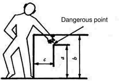
When reaching both downwards and above the safety distances set out in Table 1 must be maintained.
Table 1
|
(mm) |
||||||||
|
a: Distance from ground of dangerous point |
Height between barrier and protective device b |
|||||||
|
2 400 |
2 200 |
2 000 |
1 800 |
1 600 |
1 400 |
1 200 |
1 000 |
|
|
Horizontal distance c from dangerous point |
||||||||
|
2 400 |
— |
100 |
100 |
100 |
100 |
100 |
100 |
100 |
|
2 200 |
— |
250 |
350 |
400 |
500 |
500 |
600 |
600 |
|
2 000 |
— |
— |
350 |
500 |
600 |
700 |
900 |
1 100 |
|
1 800 |
— |
— |
— |
600 |
900 |
900 |
1 000 |
1 100 |
|
1 600 |
— |
— |
— |
500 |
900 |
900 |
1 000 |
1 300 |
|
1 400 |
— |
— |
— |
100 |
800 |
900 |
1 000 |
1 300 |
|
1 200 |
— |
— |
— |
— |
500 |
900 |
1 000 |
1 400 |
|
1 000 |
— |
— |
— |
— |
300 |
900 |
1 000 |
1 400 |
|
800 |
— |
— |
— |
— |
— |
600 |
900 |
1 300 |
|
600 |
— |
— |
— |
— |
— |
— |
500 |
1 200 |
|
400 |
— |
— |
— |
— |
— |
— |
300 |
1 200 |
|
200 |
— |
— |
— |
— |
— |
— |
200 |
1 100 |
2.3.2.3. Reach around
The safety margin shown in Table 2 below must, at the minimum, be maintained if the part of the body concerned is not to reach a dangerous point. In applying the safety margin it is assumed that the main body joint concerned is pushed firmly against the edge of the protective device. The safety margins are not considered to have been maintained until one is satisfied that part of the body may quite definitely not advance or penetrate further.
Table 2
|
Part of the body |
Safety distance |
Figure |
|
Hand From the first knuckle to the fingertips |
≥ 120 |
|
|
Hand From the wrist to the fingertips |
≥ 230 |
|
|
Limb |
Safety distance |
Illustration |
|
Arm From the elbow to the fingertips |
≥ 550 |
|
|
Arm From the shoulder to the fingertips |
≥ 850 |
|
2.3.2.4. Penetration and reach across
If penetration is possible into or across openings and up to dangerous parts, the minimum safety distances set out in Tables 3 and 4 must be maintained.
Parts which move in relation to one another or moving parts set alongside fixed parts are not regarded as risk factors provided they are no more than 8 mm apart.
Table 3
Safety distances for elongated and parallel openings
a is the smaller dimension of the aperture.
b is the safety distance from danger point
|
Fingertip |
Finger |
Hand to ball of thumb |
Arm to armpit |
— |
|
|
|
|
|
|
|
|
|
4 < a ≤ 8 |
8 < a ≤ 12 |
12 < a ≤ 20 |
20 < a ≤ 30 |
30 < a ≤ 135 maximum |
> 135 |
|
b ≥ 15 |
b ≥ 80 |
b ≥ 120 |
b ≥ 200 |
b ≥ 850 |
— |
Table 4
Safety distances for square or circular apertures
a is the aperture/diameter or length of side.
b is the safety distance from danger point.
|
Fingertip |
Finger |
Hand to thumb root |
Arm to armpit |
— |
|
|
|
|
|
|
|
|
|
4 < a ≤ 8 |
8 < a ≤ 12 |
12 < a ≤ 25 |
25 < a ≤ 40 |
40 < a ≤ 250 maximum |
250 |
|
b ≥ 15 |
b ≥ 80 |
b ≥ 120 |
b ≥ 200 |
b ≥ 850 |
— |
2.3.2.5. Safety distances at pinching points
A pinching point is not considered dangerous for the part of the body shown if the safety distances are not less than those set out in Table 5, and if it is ensured that the adjacent, wider part of the body cannot be introduced.
Table 5
|
Limb |
Body |
Leg |
Foot |
Arm |
Hand, joint, first |
Finger |
|
Safety distances |
500 |
180 |
120 |
100 |
25 |
|
|
Illustration |
|
|
|
|
|
|
2.3.2.6. Controls
The gap between two pedals and the holes through which controls pass are not regarded as being pinching or shearing points.
2.3.2.7. Rear three-point coupling
2.3.2.7.1. Behind a plane passing through the median plane of the pivot points of the lifting rods in a three-point coupling system a minimum safety margin of 25 mm must be maintained between the moving parts for each point or of the lifting device's travel — but not for the extreme upper and lower positions 0,1 n, together with a distance of 25 mm or a minimum angle of 30° for the parts in shear which cause a change in angularity (see Figure 3). Travel n′, reduced by 0,1 n at both its upper and lower ends is defined as follows (see Figure 4). Where the lower links are directly activated by the lifting mechanism, the reference plane is determined by the median transverse vertical plane of those links.


2.3.2.7.2. For travel n of the hydraulic lifting unit, lower position A of the coupling point of the lower link is limited by dimension ‘14’ in accordance with ISO Standard 730, Part 1, of December 1994 while upper position B is limited by the maximum hydraulic travel. Travel n′ corresponds to travel n reduced upwards and downwards by 0,1 n, and constitutes the vertical distance between A′ and B′.
2.3.2.7.3. Moreover, within travel n′ a minimum safety margin of 25 mm in relation to the adjacent parts must be maintained around the profile of the lifting rods.
2.3.2.7.4. If, in the case of a three-point coupling, coupling devices are used which do not require the presence of an operator between the tractor and the implement carried (for example, in the case of a quick coupling), the provisions of point 2.3.2.7.3 do not apply.
2.3.2.7.5. The operating manual should contain specific information on the dangerous points located at the front of the plane defined in the first sentence of point 2.3.2.7.1.
2.3.2.8. Front three-point coupling
2.3.2.8.1. At each point of the lifting unit’s travel n — but not for the extreme upper and lower reaches 0,1 n — a minimum safety margin of 25 mm must be maintained between the moving parts together with a minimum angle of 30° or a safety margin of 25 mm in the case of the change of angularity caused by the parts in shear with each other. Travel n′ reduced by 0,1 n at both its upper and lower ends, is defined as follows (see also Figure 4).
2.3.2.8.2. For travel n of the hydraulic lifting unit, the extreme lower position A of the coupling point of the lower link is limited by dimension ‘14’ in accordance with ISO Standard 8759, Part 2, of March 1998 while extreme upper position B is limited by the maximum hydraulic travel. Travel n′ is reduced upwards and downwards by 0,1 n and the vertical distance between A′ and B′.
2.3.2.8.3. If, for the lower links of a front three-point coupling, coupling devices (such as a rapid-action coupling) are used which do not require the presence of a person between the tractor and the implement attached during coupling, the requirements under 2.3.2.8.1 do not apply within the reach of a radius of 250 mm from the points at which the lower links are coupled to the tractor. However, a minimum safety margin of 25 mm from neighbouring parts within the defined travel n′ must in any case be maintained around the outside of the travel rods/cylinders.
2.3.2.9. Driving seat and environment
When he is in a sitting position, all pinching or shearing points must be out of range of the driver's hands or feet. This requirement is considered to have been met if the following conditions are fulfilled:
2.3.2.9.1. The driver's seat is at the mid-point in its longitudinal and vertical adjustment range. The driver's reach limit is divided into zones A and B. A central spherical point of these zones is 60 mm in front of and 580 mm above the seat index point (see Figure 5). Zone A consists of a sphere having a diameter of 550 mm while zone B is located between that sphere and a sphere having a radius of 1 000 mm.

2.3.2.9.2. A safety distance of 120 mm in zone A and 25 mm in zone B is maintained near the pinching and shearing points, whilst a minimum angle of 30° is maintained in the case of shearing parts causing a change in angularity.
2.3.2.9.3. In zone A, only the pinching and shearing points caused by parts set in motion by an outside energy source must be taken into account.
2.3.2.9.4. If a dangerous point is due to the presence of structural parts adjacent to the seat, a safety distance of a least 25 mm is maintained between that structural part and the seat. There is no dangerous point between the seat backrest and the adjacent structural parts located behind that backrest if the adjacent structural parts are smooth and the seat backrest itself is rounded in the surrounding area and has no sharp points.
2.3.2.10. Passenger seat (if any)
2.3.2.10.1. If parts may constitute a danger for the feet, provision must be made for protective devices within a hemispherical radius of 800 mm starting from the forward edge of the seat cushion and pointing downwards.
2.3.2.10.2. As described in point 2.3.2.9 (see Figure 6) the dangerous points in zones A and B must be protected within a sphere whose centre is 670 mm above the centre of the front edge of the passenger seat.

Narrow-track tractors (tractors with a track as defined in the second indent of Article 1 of Council Directive 87/402/EEC (2)).
2.3.2.11.1. In the case of narrow-track tractors, the requirements of point 2.3.2.9 do not apply to the zone situated below a plane inclined at 45° to the rear and transverse to the direction of travel, and passing through a point located 230 mm behind the seat index point (see Figure 7). If there are any dangerous points in this zone, corresponding warnings must be affixed to the tractor.
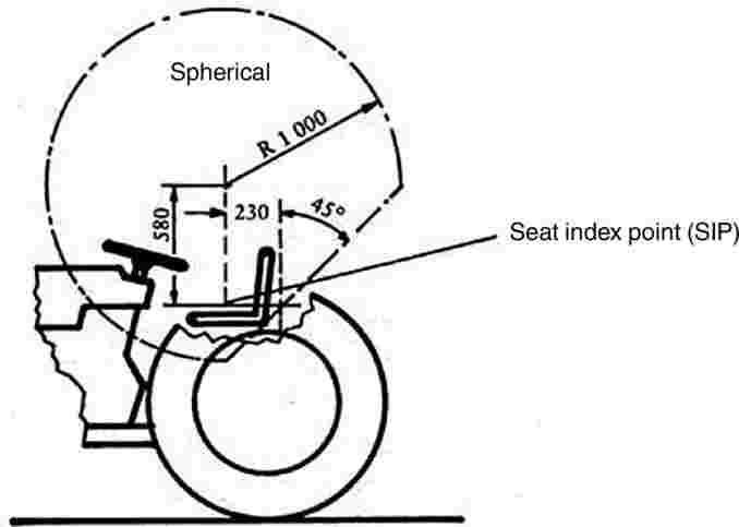
2.3.2.11.2. Sections II.1 and II.2 of Annex I to Council Directive 80/720/EEC (3) apply to access to the driver's seat.
2.3.2.11.3. Section I.6 of Annex I to Directive 80/720/EEC applies to control devices.
2.3.2.11.4. In front of a reference plane which passes at right angles to the longitudinal axis of the vehicle and through the centre of the load-free pedal (clutch and/or service brake), very hot exhaust components must be protected if located within 300 mm in the upper zone (700 mm above ground level) and within 150 mm in the lower zone (see Figure 8). Laterally, the area to be protected is limited by the external outline of the tractor and the external outline of the exhaust system.
Very hot exhaust system components passing beneath the entry step must be covered in their vertical projection or otherwise thermally protected.
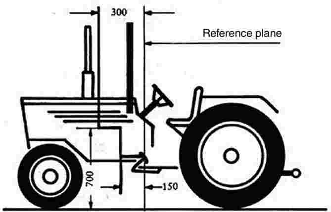
2.3.2.12. Layout and marking of flexible hydraulic hoses
2.3.2.12.1. Flexible hydraulic hoses must be arranged in such a way as to prevent mechanical and thermal damage.
2.3.2.12.2. Flexible hydraulic hoses must be clearly identifiable and indelibly marked with the following information:
|
— |
the flexible hose manufacturer's mark, |
|
— |
manufacturing date (year and month of manufacture), |
|
— |
maximum permissible dynamic excess pressure in operation. |
2.3.2.12.3. Flexible hydraulic hoses in the vicinity of the driver's or the passenger's seat must be arranged or protected in such a way that in the event of their failure there can be no danger to any person.
2.3.2.13. Steering and swing axle
Parts moving in relation to each other or to fixed parts must be protected if they lie within the zone defined in points 2.3.2.9 and 2.3.2.10.
When articulated steering is fitted, there must be indelible and clear markings within the articulation range on both sides of the tractor, indicating by means of an illustrative sign or in words that remaining within the unprotected range of articulation is not permitted. The corresponding indications must be included in the operating manual.
2.3.2.14. Transmission shafts fixed on the tractor
Transmission shafts (for example, for four-wheel drive) which can only rotate while the tractor is in motion must be protected if they are located within the zone defined in points 2.3.2.9 and 2.3.2.10.
2.3.2.15. Clearance zone around the drive wheels
2.3.2.15.1. The clearance zones of the wheel guards must meet the following requirements.
2.3.2.15.2. ‘Clearance zone’ means the space which must remain clear around the tyres of the drive wheels in relation to the adjacent parts of the vehicle.
The clearance zone of the drive wheels, when fitted with largest-size tyres, must correspond to the dimensions set out in the following Figure 9 and Table 6.
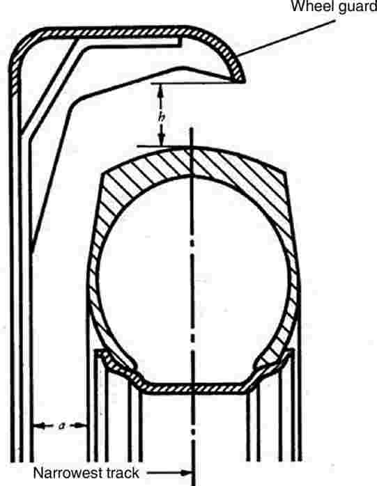
Table 6
|
Standard tractors |
Narrow track tractors |
||
|
a |
h |
a |
h |
|
mm |
mm |
mm |
mm |
|
40 |
60 |
15 |
30 |
A clearance zone smaller than that illustrated in Figure 9 and Table 6 is permissible in addition to the zones referred to in points 2.3.2.9 and 2.3.2.10 in the case of narrow-track tractors where wheel guards are also used to scrape off earth stuck to the wheels.
2.3.2.16. Hot surfaces
Hot surfaces which can be reached by the operator during normal operation of the tractor shall be covered or insulated. This applies to hot surfaces which are near to steps, handrails, handholds and integral tractor parts used as boarding means and which may be inadvertently touched.
2.3.2.17. Battery terminal cover
Non-earthed terminals must be protected against unintentional short-circuiting.
2.4. Method of determining the seat index point
2.4.1. General
The method and device used in defining the index point for any type of upholstered seat are described below.
2.4.2. Definitions
Seat index point (SIP):
Point situated in the vertical median longitudinal plane of the SIP locating device represented in Figure 10 which is placed on the driving seat in accordance with points 2.4.4 and 2.4.6.
The seat index point is established in relation to the vehicle and does not move as a function of the seat adjustments and/or oscillations.
2.4.3. Device for determining the seat index point (SIP)
The device for determining the SIP must be as shown in Figure 10. The mass of that device is 6 ± 1 kg and its underside must be flat and polished.
2.4.4. Seat setting for determination of index point (SIP)
Where a seat and its suspension can be regulated, the seat is regulated as follows before the index point is determined:
|
(a) |
all of the adjustments — back/forth, height and rake — must be in their mid-position. If this is not the case, the closest adjustment either above or below the mid-position should be used; |
|
(b) |
adjustable suspension must be adjusted in such a way that the suspension is at mid-travel with the locating device in position and loaded. The suspension may be locked mechanically in that position while the index point (SIP) is determined; |
|
(c) |
non-adjustable suspension may be locked in the vertical position that is achieved with the locating device in place and loaded; |
|
(d) |
if the adjustments mentioned above conflict with the manufacturer's specific instructions, these must be followed in such a way as to obtain the setting recommended for a 75 kg driver. |
NB: A 75 kg driver offers an approximation of the locating device in position on the seat and loaded with a mass of 65 kg.
2.4.5. Determination of the three reference axes x′, y′, and z′ for the SIP
The coordinates must be established as follows:
|
(a) |
location, on one side of the seat mounting, of the attachment hole that is in the most rear position; |
|
(b) |
if the axis of this hole is parallel to the pivot axis defined on the device, it is taken as axis y′ (pointing from left to right in relation to a seated driver — see Figure 11); |
|
(c) |
if the axis of this hole is parallel to the vertical plane passing through the centre line of the seat, the straight line is taken as axis y′ which runs parallel to the pivot axis referred to and passes through the point of intersection between the supporting plane of the seat and the hole axis referred to above (see Figure 12); |
|
(d) |
in all other cases, axis y′ is established in accordance with the parameters relating to the seat being measured; |
|
(e) |
axes x′ and z′ are defined as intersections of the horizontal and vertical planes passing through y′ with the vertical plane through the seat centre line. Axes x′ and z′ point forwards and upwards (see Figures 11 and 12). |
2.4.6. Method of determining the seat index point (SIP)
The seat index point (SIP) is determined by using the device shown in Figure 10 and by proceeding in the following manner:
|
(a) |
the seat is covered with a piece of cloth in order to facilitate correct positioning of the device; |
|
(b) |
the device is positioned on the seat cushion (without additional mass) by pushing it rearwards against the backrest; |
|
(c) |
masses are added to bring the total mass of the device from 6 ± 1 kg to 26 ± 1 kg. The centre of vertical force must be 40 mm ahead of the seat index point mark on the horizontal part of the device (see Figure 10); |
|
(d) |
a horizontal force of about 100 N is applied twice to the device on the seat index point, as set out in figure 10; |
|
(e) |
other masses are added to bring the total mass of the device from 26 ± 1 kg to 65 ± 1 kg. The centre of the vertical force of the masses added must be 40 mm ahead of the seat index point mark on the horizontal part of the device (see Figure 10); |
|
(f) |
on both sides of the seat in two vertical planes, equidistant from the median longitudinal line of the seat, the coordinates, as defined in point 2.4.5, of the intersections of those planes on the axis of the seat index point marked by the device must be measured to ±1 mm. The arithmetical mean values of the measurements taken in the two planes are recorded as SIP coordinates; |
|
(g) |
the conditions resulting from the method of determination, and which diverge from the procedure set out in this Annex, or which may be the source of errors as regards their results, may be noted, as may their causes. |
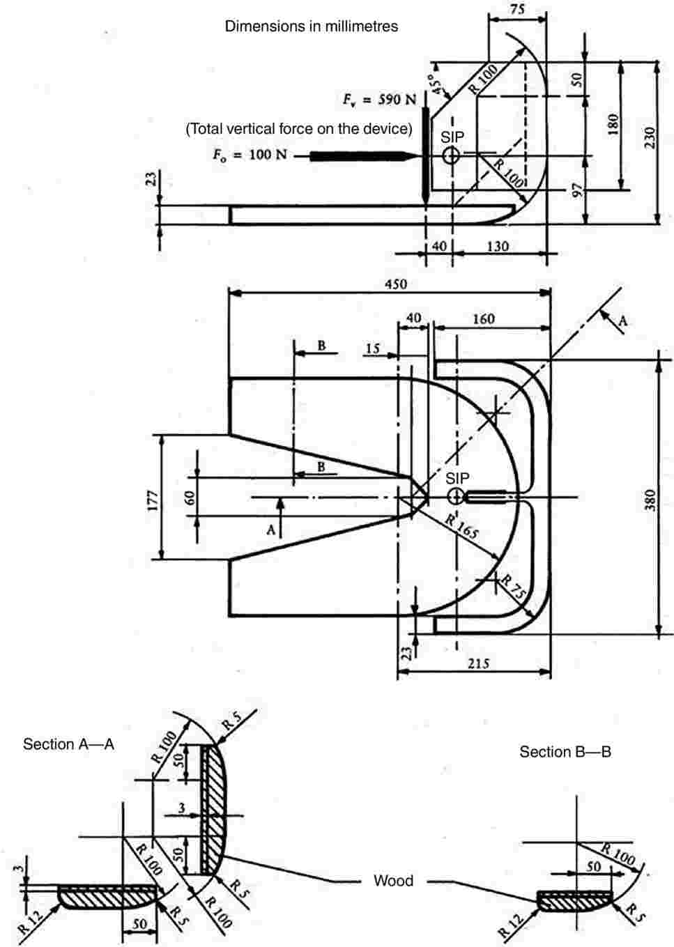


(1) Directive 2009/60/EC of the European Parliament and of the Council of 13 July 2009 on the maximum design speed of and load platforms for wheeled agricultural or forestry tractors (Codified version) (OJ L 198, 30.7.2009, p. 15).
(2) Council Directive 87/402/EEC of 25 June 1987 on roll- over protection structures mounted in front of the driver's seat on narrow-track wheeled agricultural and forestry tractors (OJ L 220, 8.8.1987, p. 1).
(3) Council Directive 80/720/EEC of 24 June 1980 on the approximation of the laws of the Member States relating to the operating space, access to the driving position and the doors and windows of wheeled agricultural or forestry tractors (OJ L 194, 28.7.1980, p. 1).
Appendix
MODEL
ANNEX TO THE EC TYPE-APPROVAL CERTIFICATE FOR A TYPE OF TRACTOR WITH REGARD TO THE SPEED GOVERNOR AND PROTECTION OF THE DRIVE COMPONENTS, PROJECTIONS AND WHEELS
(Article 4(2) of Directive 2003/37/EC of the European Parliament and of the Council of 26 May 2003 on type-approval of agricultural or forestry tractors, their trailers and interchangeable towed machinery, together with their systems, components and separate technical units)
EC type-approval No: …
Component(s) or characteristic(s):
1.1. speed governor (where present)
1.2. protection of the drive units, projection and wheels
2. Make of tractor (or business name of manufacturer):
…
…
3. Type and where appropriate commercial name of tractor:
…
…
4. Manufacturer's name and address:
…
…
5. If applicable, name and address of manufacturer's authorised representative:
…
…
6. Description of component(s) and/or characteristic(s) mentioned under 1 above:
…
7. Date of submission of tractor for EC type-approval:
…
8. Technical service conducting the type-approval tests:
…
…
9. Date of report issued by that service:
…
10. Number of report issued by that service:
…
11. EC type-approval for the speed governor and protection of the drive components, projections and wheels is granted/refused (1):
12. Place: …
13. Date: …
14. Signature: …
15. The following documents, bearing the EC type-approval number indicated above, are attached to this certificate:
… dimensioned drawings;
… drawing or photograph of the relevant parts of the tractor.
The data must be supplied to the competent authorities of the other Member States if they so request.
16. Remarks:
…
…
(1) Delete where appropriate.
ANNEX III A
Windscreen and other glazing Equipment requirements, definitions, application for component type-approval, component type-approval, markings, general specifications, tests and conformity of production
1. EQUIPMENT REQUIREMENTS
Agricultural and forestry tractors may be equipped as chosen by their manufacturer with:
1.1.1. windscreens and glass panes other than windscreens covered by the provisions of this Annex;
1.1.2. windscreens covered by the requirements for glass panes other than windscreens in this Annex, with the exception of the requirements of point 9.1.4.2 of Annex III C to this Directive (glass panes with a regular light transmittance of less than 70 %).
1.1.3. rigid plastic glazing is permitted for non-windscreen applications as approved in Council Directive 92/22/EEC (1) or in UNECE Regulation No 43, Annex 14.
2. DEFINITIONS
For the purposes of this Directive:
2.1. ‘toughened-glass pane’ means a glass pane consisting of a single layer of glass which has been subjected to special treatment to increase its mechanical strength and condition its fragmentations after shattering;
‘laminated-glass pane’ means a glass pane consisting of two or more layers of glass held together by one or more interlayers of plastic material; it may be:
2.2.1. ‘ordinary’, where none of the layers of glass of which it is composed have been treated, or
2.2.2. ‘treated’, where at least one of the layers of glass of which it is composed has been specially treated to increase its mechanical strength and to condition its fragmentation after shattering;
2.3. ‘safety glazing coated with plastic material’ means a glass pane as defined in point 2.1 or 2.2 with a layer of plastic material on its inner surface;
2.4. ‘glass-plastic safety glazing’ means a pane of laminated glass having one layer of glass and one or more layers of plastic material at least one of which acts as interlayer. The plastic layers shall be on the inner face when the glazing is fitted on the tractor;
‘group of windscreens’ means a group comprising windscreens of differing sizes and shapes subjected to an examination of their mechanical properties, their mode of fragmentation and their behaviour in environmental resistance tests;
2.5.1. ‘flat windscreen’ means a windscreen exhibiting no nominal curvature resulting in a height of segment exceeding 10 mm per linear metre;
2.5.2. ‘curved windscreen’ means a windscreen exhibiting nominal curvature resulting in a height of segment exceeding 10 mm per linear metre;
2.6. ‘double window’ means a set of two panes installed separately in the same opening on the tractor;
‘double glazing’ means a unit composed of two panes permanently assembled in the factory and separated by a uniform gap;
2.7.1. ‘symmetrical double glazing’ means double glazing in which the two constituent panes are of the same type (toughened or laminated glass, etc.), and exhibit identical principal and secondary characteristics;
2.7.2. ‘asymmetrical double glazing’ means double glazing in which the two constituent panes are of a different type (toughened or laminated glass, etc.) or exhibit different principal and/or secondary characteristics;
2.8. ‘principal characteristic’ means a characteristic which appreciably modifies the optical and/or mechanical properties of a pane of glass in a way not without significance to the function which the glass pane is to perform in a tractor. This term also covers the trade name or mark;
2.9. ‘secondary characteristic’ means a characteristic capable of modifying the optical and/or mechanical properties of a pane of glass in a way which is of significance to the function which the glass pane is intended to perform in a tractor. The extent of such modification is assessed in relation to the indices of difficulty;
2.10. ‘indices of difficulty’ covers a two-stage grading system applying to the variations observed in practice in each secondary characteristic. A change from index ‘1’ to index ‘2’ indicates the need for additional tests;
2.11. ‘developed area of a windscreen’ means the minimum rectangular area of glass from which a windscreen can be manufactured;
‘rake angle of a windscreen’ means the angle included between a vertical line and a straight line passing through the top and bottom extremities of the windscreen, both lines lying in a vertical plane along the longitudinal axis of the tractor.
2.12.1. Measurement of the rake angle is performed on an unladen tractor standing on level ground.
2.12.2. Tractors equipped with hydropneumatic, hydraulic or pneumatic suspension or with a device for automatic adjustment of ground clearance according to load are tested in the normal running conditions specified by the manufacturer;
2.13. ‘height of segment, h’ means the maximum distance, measured at right angles approximately to the glass pane, separating the inner surface of the pane from a pane passing through the ends of the pane (see Annex III N, Figure 1);
‘type of glass pane’ means a glass pane, as defined in points 2.1 to 2.4, not exhibiting any essential differences in respect, in particular, of the principal and secondary characteristics mentioned in Annexes III D to III L.
2.14.1. Although a change in the principal characteristics implies that the product is of a new type, it is recognised that in certain cases a change in shape and dimension does not necessarily require a complete set of tests to be carried out. For certain of the tests prescribed in the individual Annexes, glass panes may be grouped together if it is evident that they have similar principal characteristics.
2.14.2. Glass panes exhibiting differences only as regards their secondary characteristics may be deemed to be of the same type; certain tests may, however, be carried out on samples of such panes if the performance of those tests is explicitly stipulated in the test conditions;
2.15. ‘curvature, r’ means the approximate value of the smallest radius of arc of the windscreen as measured in the area of maximum curvature.
3. APPLICATION FOR COMPONENT TYPE-APPROVAL
3.1. The application for EC component type-approval for a type of glass pane is submitted by the manufacturer of the safety-glass pane or by his duly accredited representative for each type of safety glass. The application may be made in one Member State only.
For each type of safety glass, the application is accompanied by the undermentioned documents in triplicate and by the following particulars:
a technical description comprising all principal and secondary characteristics; and,
3.2.1.1. in the case of glazing other than windscreens, drawings in a format not exceeding A4 or folded to that format, showing:
|
— |
the maximum area, |
|
— |
the smallest angle between two adjacent sides of the glass pane, and |
|
— |
the maximum height of segment, if any; |
In the case of windscreens:
3.2.1.2.1. a list of the models of windscreen for which component type-approval is sought, giving the name of the tractor manufacturers and the type(s) of tractor;
drawings on a scale 1:10 and diagrams of the windscreens and their installation in the tractor in sufficient detail to show:
3.2.1.2.2.1. the position of the windscreen relative to the R point as defined in point 1.2 of Annex I to Directive 2008/2/EC (2);
3.2.1.2.2.2. the rake angle of the windscreen;
3.2.1.2.2.3. the position and size of the zone in which the optical qualities are verified and, where appropriate, the area subjected to differential toughening;
3.2.1.2.2.4. the developed area of the windscreen;
3.2.1.2.2.5. the maximum height of segment of the windscreen; and
3.2.1.2.2.6. the curvature of the windscreen (for windscreen-grouping purposes only);
3.2.1.3. in the case of double glazing, drawings in a format not exceeding A4 or folded to that format, showing, in addition to the information referred to in point 3.2.1.1:
|
— |
the type of each constituent glass pane, |
|
— |
the type of bonding (organic, glass-glass or glass-metal), |
|
— |
the nominal thickness of the gap between the two glass panes. |
3.3. In addition, the applicant must submit a sufficient number of test pieces and samples of the finished glass panes of the models considered, the number being if necessary determined by agreement with the technical service responsible for conducting the tests.
3.4. The competent authority must verify the existence of satisfactory arrangements for ensuring effective control of conformity of production before component type-approval is granted.
4. MARKINGS
4.1. Every safety-glass pane, including the samples and test-pieces submitted for component type-approval, must bear the trade name or mark of the manufacturer. The marking must be clearly legible and indelible.
5. COMPONENT TYPE-APPROVAL
5.1. If the samples submitted for component type-approval meet the requirements of points 5 to 7 below, approval of the pertinent type of safety-glass pane is granted.
5.2. A component type-approval number is assigned to each type as defined in Annexes III E, III G, III K and III L, or, in the case of windscreens, to each group approved. Its first two digits (at present 00 for Directive 89/173/EEC in its original form) indicate the series of amendments incorporating the most recent major technical amendments made to Directive 89/173/EEC as replaced by this Directive at the time of issue of the approval. A Member State may not assign the same number to another type or group of safety-glass panes.
Component type-approval or extension or refusal of approval for a type of safety-glass pane pursuant to this Directive is communicated to the Member States by means of a notice prepared in accordance with the model set out in Annex III B to this Directive and its Appendices.
5.3.1. In the case of windscreens, the EC component type-approval notice must be accompanied by a document listing every windscreen model in the approved group, together with the characteristics of the group, in accordance with Appendix 8 to Annex III B.
In addition to the marking specified in point 4.1, an EC component type-approval mark must be affixed conspicuously to all safety-glass panes and double-glazed units conforming to a type approved under this Directive. Any special component type-approval mark assigned to each pane of a double-glazed unit may also be affixed.
This component type-approval mark consists of:
5.4.1. a rectangle surrounding the lower-case letter ‘e’ followed by the distinguishing number of the country which has granted the approval (3);
5.4.2. the component type-approval number to the right of the rectangle prescribed in point 5.4.1.
The following additional symbols are affixed near the above EC type-approval mark:
5.5.1. in the case of a windscreen:
|
I |
: |
for toughened glass (I/P if faced) (4), |
|
II |
: |
for ordinary laminated glass (II/P if faced) (4), |
|
III |
: |
for treated laminated glass (III/P if faced) (4), |
|
IV |
: |
for glass-plastic glazing; |
|
V |
: |
in the case of a glass pane other than a windscreen covered by the provisions of point 9.1.4.2 of Annex III C; |
|
VI |
: |
in the case of a double-glazed unit; |
|
T |
: |
in the case of windscreens which comply with the requirements for glass panes other than windscreens, except those coming under the provisions of point 9.1.4.2 of Annex III C (glass panes with a regular light transmittance of less than 70 %). However, in the case of windscreens complying with the requirements for glass panes other than windscreens, the symbol ‘T’ may only be marked after the head-form test defined in point 3.3.2 of Annex III G, the height of drop being 4,0 m + 25/ – 0 mm. |
5.6. The EC component type-approval mark and the symbol must be clearly legible and indelible.
5.7. The Appendix to this Annex gives examples of component type-approval marks.
6. GENERAL REQUIREMENTS
6.1. All glass panes, and particularly those intended for the manufacture of windscreens, must be of sufficient quality to reduce the risk of bodily injury as far as possible in the event of the glass shattering. The glass must be sufficiently resistant to the incidents likely to occur in normal traffic, and to atmospheric and temperature conditions, chemical action, combustion and abrasion.
6.2. Safety glass must in addition be sufficiently transparent, must not cause any noticeable distortions of objects as seen through the windscreen, and must not give rise to any confusion between the colours used in road-traffic signs and signals. In the event of the windscreen shattering, the driver must still be able to see the road clearly enough to be able to brake and stop his tractor safely.
7. PARTICULAR REQUIREMENTS
All types of safety glass must, depending on the category to which they belong, comply with the following particular requirements:
7.1. as regards toughened-glass windscreens, the requirements contained in Annex III D;
7.2. as regards uniformly toughened glass panes other than windscreens, the requirements contained in Annex III E;
7.3. as regards ordinary laminated-glass windscreens, the requirements contained in Annex III F;
7.4. as regards ordinary laminated-glass panes other than windscreens, the requirements contained in Annex III G;
7.5. as regards treated laminated-glass windscreens, the requirements contained in Annex III H;
7.6. as regards safety-glass panes faced with plastic material, in addition to the relevant requirements listed above, the requirements contained in Annex III I;
7.7. as regards glass-plastic windscreens, the requirements contained in Annex III J;
7.8. as regards glass-plastic panes other than windscreens, the requirements contained in Annex III K;
7.9. as regards double-glazed units, the requirements contained in Annex III L.
8. TESTS
The following tests are prescribed:
8.1.1. Fragmentation
The purpose of this test is:
8.1.1.1. to verify that the fragments and splinters produced by fracture of the pane of glass are such as to minimise the risk of injury, and
8.1.1.2. in the case of windscreens, to check residual visibility after shattering.
8.1.2. Mechanical strength
8.1.2.1. Ball-impact test
This test takes two forms, one using a 227 g ball and the other a 2 260 g ball.
8.1.2.1.1. 227-g-ball test: the purpose of this test is to assess the adhesion of the interlayer in laminated glass and the mechanical strength of uniformly toughened glass.
8.1.2.1.2. 2 260-g-ball test: the purpose of this test is to assess the ball-penetration resistance of laminated glass.
8.1.2.2. Headform test
The purpose of this test is to verify the glass pane's compliance with requirements relating to the limitation of injury in the event of impact of the head against the windscreen, laminated glass or glass-plastic panes other than windscreens, and also double-glazed units used as side windows.
8.1.3. Resistance to the environment
8.1.3.1. Abrasion test
The purpose of this test is to determine whether the resistance of a safety-glass pane to abrasion exceeds a specified value.
8.1.3.2. High-temperature test
The purpose of this test is to verify that no bubbles or other defects occur in the interlayer in a laminated glass or glass-plastic pane when the latter is exposed to high temperatures over an extended period of time.
8.1.3.3. Resistance-to-radiation test
The purpose of this test is to determine whether the light transmittance of laminated-glass, glass-plastic or plastic-coated glass panes exposed to radiation over an extended period of time is significantly reduced thereby or whether the glazing is significantly discoloured.
8.1.3.4. Resistance-to-humidity test
The purpose of this test is to determine whether a laminated-glass, glass-plastic or plastic-coated glass pane will withstand, without significant deterioration, the effects of prolonged exposure to atmosphere humidity.
8.1.3.5. Resistance to temperature change
The purpose of this test is to determine whether the plastic material(s) used in safety glazing as defined in points 2.3 and 2.4 will withstand, without significant deterioration, the effects of prolonged exposure to extreme temperatures.
8.1.4. Optical qualities
8.1.4.1. Light-transmission test
The purpose of this test is to determine whether the regular transmittance of safety-glass panes exceeds a specified value.
8.1.4.2. Optical-distortion test
The purpose of this test is to verify that the distortion of objects as seen through the windscreen is not such as to be likely to confuse the driver.
8.1.4.3. Secondary-image-separation test
The purpose of this test is to verify that the angular separation of the secondary image from the primary image does not exceed a specified value.
8.1.4.4. Identification-of-colours test
The purpose of this test is to verify that there is no risk of confusion of colours as seen through a windscreen.
8.1.5. Fire-resistance test
The purpose of this test is to verify that the inner face of a safety-glass pane as defined in points 2.3 and 2.4 has a sufficiently low burn rate.
8.1.6. Resistance to chemical agents
The purpose of this test is to determine that the inner face of a safety-glass pane as defined in points 2.3 and 2.4 will withstand the effects of exposure to chemicals likely to be present or used within the tractor (e.g. cleaning compounds) without deterioration.
8.2. Tests prescribed for glass panes of the categories defined in points 2.1 to 2.4
8.2.1. Safety-glass panes are subject to the tests listed in the following table:
|
|
Windscreens |
Glass panes other than windscreens |
||||||||
|
Toughened glass |
Ordinary laminated glass |
Treated laminated glass |
Glass-plastic |
Toughened glass |
Laminated glass |
Glass-plastic |
||||
|
I |
I/P |
II |
II/P |
III |
III/P |
IV |
||||
|
Fragmentation |
D/2 |
D/2 |
— |
— |
H/4 |
H/4 |
— |
E/2 |
— |
— |
|
Mechanical strength: |
|
|
|
|
|
|
|
|
|
|
|
227 g ball |
— |
— |
F/4.3. |
F/4.3. |
F/4.3. |
F/4.3. |
F/4.3. |
E/3.1. |
G/4 |
G/4 |
|
2 260 g ball |
— |
— |
F/4.2. |
F/4.2. |
F/4.2. |
F/4.2. |
— |
— |
— |
— |
|
Headform test (5) |
D/3 |
D/3 |
F/3 |
F/3 |
F/3 |
F/3 |
J/3 |
— |
G/3 (7) |
K/3 (7) |
|
Abrasion: |
|
|
|
|
|
|
|
|
|
|
|
outer face |
— |
— |
F/5.1. |
F/5.1. |
F/5.1. |
F/5.1. |
F/5.1. |
— |
F/5.1. |
F/5.1. |
|
inner face |
— |
I/2 |
— |
I/2 |
— |
I/2 |
I/2 |
I/2 (6) |
I/2 (6) |
I/2 |
|
High temperature |
— |
— |
C/5 |
C/5 |
C/5 |
C/5 |
C/5 |
— |
C/5 |
C/5 |
|
Radiation |
— |
C/6 |
C/6 |
C/6 |
C/6 |
C/6 |
C/6 |
— |
C/6 |
C/6 |
|
Humidity |
— |
C/7 |
C/7 |
C/7 |
C/7 |
C/7 |
C/7 |
C/7 (6) |
C/7 |
C/7 |
|
Light transmission |
C/9.1. |
C/9.1. |
C/9.1. |
C/9.1. |
C/9.1. |
C/9.1. |
C/9.1. |
C/9.1. |
C/9.1. |
C/9.1. |
|
Optical distortion |
C/9.2. |
C/9.2. |
C/9.2. |
C/9.2. |
C/9.2. |
C/9.2. |
C/9.2. |
— |
— |
— |
|
Secondary image |
C/9.3. |
C/9.3. |
C/9.3. |
C/9.3. |
C/9.3. |
C/9.3. |
C/9.3. |
— |
— |
— |
|
Identification of colours |
C/9.4. |
C/9.4. |
C/9.4. |
C/9.4. |
C/9.4. |
C/9.4. |
C/9.4. |
— |
— |
— |
|
Resistance to temperature changes |
— |
C/8 |
— |
C/8 |
— |
C/8 |
C/8 |
C/8 (6) |
C/8 (6) |
C/8 |
|
Fire resistance |
— |
C/10 |
— |
C/10 |
— |
C/10 |
C/10 |
C/10 (6) |
C/10 (6) |
C/10 |
|
Resistance to chemicals |
— |
C/11 |
— |
C/11 |
— |
C/11 |
C/11 |
C/11 (6) |
C/11 (6) |
C/11 |
|
NB: A reference such as K/3 in the table indicates Annex III K and point 3 of that Annex, where the relevant test is described and the acceptance requirements specified. |
||||||||||
8.2.2. A safety-glass pane is granted component type-approval if it meets all the requirements prescribed in the relevant provisions referred to in the above table.
9. MODIFICATION OR EXTENSION OF APPROVAL FOR A TYPE OF SAFETY-GLASS PANE
All modifications to a type of safety-glass pane, or, in the case of windscreens, all additions of windscreens to a group, must be notified to the administrative department which approved the type of safety-glass pane. The department may then either:
9.1.1. consider that the modifications made are unlikely to have an appreciable adverse effect and, in the case of windscreens, that the new type comes within the approved group of windscreens, and that at all events the safety-glass pane still complies with the requirements, or
9.1.2. require a further test report from the technical service responsible for conducting the tests.
9.2. Communication
9.2.1. Confirmation, refusal or extension of component type-approval are communicated to the Member States in accordance with the procedure specified in point 5.3.
9.2.2. The competent authority which has granted an extension of component type-approval must place a serial number on each communication relating to the extension.
10. CONFORMITY OF PRODUCTION
10.1. Safety glazing granted type-approval under this and the following Annexes must be so manufactured as to conform to the approved type and meet the requirements set out in points 6, 7 and 8.
10.2. To verify that the requirements of point 10.1 have been met, constant checks must be carried out on production.
The holder of the component type-approval must in particular:
10.3.1. ensure that procedures exist for controlling the quality of the product,
10.3.2. have access to the equipment necessary for checking conformity to each approved type,
10.3.3. record data of test results and make the ancillary documents (8) available for a period to be determined in agreement with the administrative department,
10.3.4. analyse the results of each type of test to verify and ensure consistency of the product characteristics, allowing for the permissible variations in industrial production,
10.3.5. ensure that, for each type of product, at least the tests prescribed in Annex III O are carried out, and
10.3.6. ensure that where any samples or test-pieces show non-conformity with the type of test concerned, further samples are taken and tested.
All necessary steps must be taken to re-establish conformity in the production concerned.
The competent authority may at any time verify the methods for checking conformity applicable to each production unit (see point 1.3 of Annex III O).
10.4.1. At every inspection, the test data and production records must be presented to the inspector.
10.4.2. The inspector may take samples at random to be tested in the manufacturer's laboratory. The minimum number of samples may be determined in the light of the results of the manufacturer's own checks.
10.4.3. Where the quality standard appears unsatisfactory or where it appears necessary to verify the validity of the tests carried out under point 10.4.2, the inspector may select samples to be sent to the technical service which conducted the component type-approval test.
10.4.4. The competent authority may carry out any test prescribed in this Directive.
10.4.5. The normal frequency of inspection is two per year. If unsatisfactory results are found during any of these inspections, the competent authority must ensure that all necessary steps are taken to re-establish the conformity of production as quickly as possible.
11. PENALTIES FOR NON-CONFORMITY OF PRODUCTION
11.1. Component type-approval granted in respect of a type of safety-glass pane pursuant to this Directive may be withdrawn if the requirement laid down in point 10.1 is not complied with.
11.2. If a Member State withdraws an approval it has previously granted, it must forthwith notify the other Member States thereof by means of a copy of the component type-approval certificate with ‘COMPONENT TYPE-APPROVAL WITHDRAWN’ added in large letters at the bottom of the certificate, and signed and dated.
12. PRODUCTION DEFINITELY DISCONTINUED
If the holder of component type-approval completely ceases to manufacture a type of safety-glass pane approved in accordance with this Directive, he must inform thereof the authority which granted the approval. That authority must in turn notify the other Member States thereof, by means of a copy of the compound type-approval notice conforming to the model shown in Annex III B.
13. NAMES AND ADDRESSES OF THE TECHNICAL SERVICES RESPONSIBLE FOR CONDUCTING COMPONENT TYPE-APPROVAL TESTS AND OF THE ADMINISTRATIVE DEPARTMENTS GRANTING SUCH APPROVAL
Each Member State must communicate to the other Member States and the Commission the names and addresses of the technical services responsible for conducting component type-approval tests and of the administrative departments granting EC component type-approval, to which the component type-approval certificate and certificates indicating refusal or withdrawal of component type-approval issued in the other Member States are to be sent.
(1) Council Directive 92/22/EEC of 31 March 1992 on safety glazing and glazing materials on motor vehicles and their trailers (OJ L 129, 14.5.1992, p. 11).
(2) Directive 2008/2/EC of the European Parliament and of the Council of 15 January 2008 on the field of vision and windscreen wipers for wheeled agricultural or forestry tractors (Codified version) (OJ L 24, 29.1.2008, p. 30).
(3) 1 for Germany, 2 for France, 3 for Italy, 4 for the Netherlands, 5 for Sweden, 6 for Belgium, 7 for Hungary, 8 for the Czech Republic, 9 for Spain, 11 for the United Kingdom, 12 for Austria, 13 for Luxembourg, 17 for Finland, 18 for Denmark, 19 for Romania, 20 for Poland, 21 for Portugal, 23 for Greece, 24 for Ireland, 26 for Slovenia, 27 for Slovakia, 29 for Estonia, 32 for Latvia, 34 for Bulgaria, 36 for Lithuania, 49 for Cyprus and 50 for Malta.
(4) As defined in point 2.3.
(5) Furthermore this test must be carried out on double-glazed units pursuant to point 3 of Annex III L.
(6) If coated on the inner side with plastic material.
(7) This list must be performed with a drop of 4 m + 25/ – 0 mm instead of 1,5 m + 25/ – 0 mm when the panes are used as tractor windscreens.
NB: A reference such as K/3 in the table indicates Annex III K and point 3 of that Annex, where the relevant test is described and the acceptance requirements specified.
(8) Fragmentation test results must be recorded even if no photographic print is required.
Appendix
EXAMPLES OF COMPONENT TYPE-APPROVAL MARKS
(See point 5.5 of Annex III A)
Toughened-glass windscreens:
The above component type-approval mark, affixed to a toughened-glass windscreen, shows that the component concerned was approved in France (e 2) pursuant to this Directive under component type-approval number 001247.
Toughened-glass windscreens faced with plastic material:

The above component type-approval mark affixed to a toughened-glass windscreen faced with plastic material shows that the component concerned was approved in France (e 2) pursuant to this Directive under component type-approval number 001247.
Ordinary laminated-glass windscreens:

The above component type-approval mark affixed to an ordinary laminated-glass windscreen shows that the component concerned was approved in France (e 2) pursuant to this Directive under component type-approval number 001247.
Ordinary laminated-glass windscreens faced with plastic material:

The above component type-approval mark affixed to an ordinary laminated-glass windscreen faced with plastic material shows that the component concerned was approved in France (e 2) pursuant to this Directive under component type-approval number 001247.
Treated laminated-glass windscreens:
The above component type-approval mark affixed to a treated laminated-glass windscreen shows that the component concerned was approved in France (e 2) pursuant to this Directive under component type-approval number 001247.
Glass-plastic windscreens:
The above component type-approval mark affixed to a glass-plastic windscreen shows that the component concerned was approved in France (e 2) pursuant to this Directive under component type-approval number 001247.
Glass panes other than windscreens having a regular light transmittance of less than 70 %:

The above component type-approval mark affixed to a glass pane other than a windscreen to which the requirements of point 9.1.4.2 of Annex III C are applicable shows that the component concerned was approved in France (e 2) pursuant to this Directive under component type-approval number 001247.
Double-glazed units having a regular light transmittance of less than 70 %:

The above component type-approval mark affixed to a double-glazed unit shows that the component concerned was approved in France (e 2) pursuant to this Directive under component type-approval number 001247.
Glass panes other than windscreens to be used as windscreens for tractors:

The above component type-approval mark affixed to a glass pane shows that the component concerned intended to be used as a windscreen on a tractor was approved in France (e 2) pursuant to this Directive under component type-approval number 001247.
Glass panes other than windscreens having a regular light transmittance of 70 % more:

The above component type-approval mark affixed to a glass pane other than a windscreen to which the requirements of point 9.1.4.1 of Annex III C are applicable shows that the component concerned was approved in France (e 2) pursuant to this Directive under component type-approval number 001247.
ANNEX III B
(Maximum format: A4 (210 × 297 mm))
Communication on
|
— |
EC component type-approval, |
|
— |
refusal of component type-approval, |
|
— |
extension of component type-approval, |
|
— |
withdrawal of component type-approval (1) for a type of safety-glass pane pursuant to Directive 2009/144/EC |
EC component type-approval No: … Extension No …
1. Category of safety-glass pane:
…
2. Description of glass pane (see Appendices 1, 2, 3, 4, 5, 6, 7 (1)) and, in the case of windscreens, the list conforming with Appendix 8:
…
…
3. Trade name or mark:
…
4. Manufacturer's name and address:
…
…
5. Name and address of manufacturer's representative where applicable:
…
6. Submitted for component type-approval on:
…
7. Technical service responsible for conducting component type-approval tests:
…
8. Date of test report:
…
9. Number of test report:
…
10. Component type-approval granted/refused/extended/withdrawn (1):
…
11. Grounds for extending type-approval:
…
…
…
12. Remarks:
…
…
…
13. Place: …
14. Date: …
15. Signature: …
16. A list is attached of the documents comprising the component type-approval file lodged with the administrative department granting the approval; these documents are available on request.
(1) Delete where appropriate.
Appendix 1
TOUGHENED-GLASS WINDSCREENS
(Principal and secondary characteristics as defined in Annex III D or III I)
Component type-approval No: … Extension No: …
Principal characteristics
|
— |
Shape category: … |
|
— |
Thickness category: … |
|
— |
Nominal thickness of the windscreen: … |
|
— |
Nature and type of plastic coating(s): … |
|
— |
Thickness of plastic coating(s): … |
Secondary characteristics
|
— |
Nature of the material (plate, float, sheet glass): |
|
— |
Colouring of glass: … |
|
— |
Colouring of plastic coating(s): … |
|
— |
Conductors incorporated (yes/no): |
|
— |
Anti-glare strips incorporated (yes/no): |
Remarks:
…
…
…
…
…
Documents attached: list of windscreen (see Appendix 8).
Appendix 2
UNIFORMLY TOUGHENED-GLASS PANES OTHER THAN WINDSCREENS
(Principal and secondary characteristics as defined in Annex III E or III I)
Component type-approval No: … Extension No: …
Principal characteristics
|
— |
Other than windscreens (yes/no): |
|
— |
Windscreen for tractor(s): … |
|
— |
Shape category: … |
|
— |
Nature of toughening process: … |
|
— |
Thickness category: … |
|
— |
Nature and type of plastic coating(s): … |
Secondary characteristics
|
— |
Nature of the material (plate, float, sheet glass): … |
|
— |
Colouring of glass: … |
|
— |
Colouring of plastic coating(s): … |
|
— |
Conductors incorporated (yes/no): |
|
— |
Anti-glare strips incorporated (yes/no): |
Approved criteria
|
— |
Greatest area (flat glass): … |
|
— |
Smallest angle: … |
|
— |
Greatest developed area (curved glass): … |
|
— |
Greatest height of segment: … |
Remarks:
…
…
…
…
…
Documents attached: list of windscreen (if applicable) (see Appendix 8).
Appendix 3
LAMINATED-GLASS WINDSCREENS
(ordinary, treated or plastic-coated)
(Principal and secondary characteristics as defined in Annex III F, III H or III I)
Component type-approval No: … Extension No: …
Principal characteristics
|
— |
Number of layers of glass: … |
|
— |
Number of layers of interlayer: … |
|
— |
Nominal thickness of the windscreen: … |
|
— |
Nominal thickness of interlayer(s): … |
|
— |
Special treatment of glass: … |
|
— |
Nature and type of interlayer(s): … |
|
— |
Nature and type of plastic coating(s): … |
Secondary characteristics
|
— |
Nature of the material (plate, float, sheet glass):… |
|
— |
Colouring of glass (colourless/tinted): … |
|
— |
Colouring of plastic coating(s) (total/partial): … |
|
— |
Conductors incorporated (yes/no): |
|
— |
Anti-glare strips incorporated (yes/no): |
Remarks:
…
…
…
…
…
Documents attached: list of windscreen (see Appendix 8).
Appendix 4
LAMINATED-GLASS PANES OTHER THAN WINDSCREENS
(Principal and secondary characteristics as defined in Annex III G or III I)
Component type-approval No: … Extension No: …
Principal characteristics
|
— |
Other than windscreens (yes/no): |
|
— |
Windscreen for tractor(s): … |
|
— |
Number of layers of glass: … |
|
— |
Number of layers of interlayer: … |
|
— |
Thickness category: … |
|
— |
Nominal thickness of interlayer(s): … |
|
— |
Special treatment of glass: … |
|
— |
Nature and type of interlayer(s): … |
|
— |
Nature and type of plastic coating(s): … |
|
— |
Thickness of plastic coating(s): … |
Secondary characteristics
|
— |
Nature of the material (plate, float, sheet glass): … |
|
— |
Colouring of interlayer (total/partial): … |
|
— |
Colouring of glass: … |
|
— |
Colouring of plastic coating(s): … |
|
— |
Conductors incorporated (yes/no): |
|
— |
Anti-glare strips incorporated (yes/no): |
Remarks:
…
…
…
…
…
Documents attached: list of windscreen (if applicable) (see Appendix 8).
Appendix 5
GLASS-PLASTIC WINDSCREENS
(Principal and secondary characteristics as defined in Annex III J)
Component type-approval No: … Extension No: …
Principal characteristics
|
— |
Shape category: … |
|
— |
Number of layers of plastic: … |
|
— |
Nominal thickness of glass: … |
|
— |
Treatment of the glass (yes/no): |
|
— |
Nominal thickness of the windscreen: … |
|
— |
Nominal thickness of the layer(s) of plastic acting as interlayer: … |
|
— |
Nature and type of layer(s) of plastic acting as interlayer: … |
|
— |
Nature and type of the outer layer of plastic: … |
Secondary characteristics
|
— |
Nature of the material (plate, float, sheet glass): … |
|
— |
Colouring of glass: … |
|
— |
Colouring of the layer(s) of plastic (total/partial): … |
|
— |
Conductors incorporated (yes/no): |
|
— |
Anti-glare strips incorporated (yes/no): |
Remarks:
…
…
…
…
…
Documents attached: list of windscreen (see Appendix 8).
Appendix 6
GLASS-PLASTIC PANES OTHER THAN WINDSCREENS
(Principal and secondary characteristics as defined in Annex III K)
Component type-approval No: … Extension No: …
Principal characteristics
|
— |
Other than windscreens (yes/no): |
|
— |
Windscreen for tractor(s): … |
|
— |
Number of layers of plastic: … |
|
— |
Thickness of the glass component: … |
|
— |
Treatment of the glass component (yes/no): |
|
— |
Nominal thickness of the pane: … |
|
— |
Nominal thickness of the layer(s) of plastic acting as interlayer: … |
|
— |
Nature and type of layer(s) of plastic acting as interlayer: … |
|
— |
Nature and type of the outer layer of plastic: … |
Secondary characteristics
|
— |
Nature of the material (plate, float, sheet glass): … |
|
— |
Colouring of glass (colourless/tinted): … |
|
— |
Colouring of the layer(s) of plastic (total/partial): … |
|
— |
Conductors incorporated (yes/no): |
|
— |
Anti-glare strips incorporated (yes/no): |
Remarks:
…
…
…
…
…
Documents attached: list of windscreen (if applicable) (see Appendix 8).
Appendix 7
DOUBLE-GLAZED UNITS
(Principal and secondary characteristics as defined in Annex III L)
Component type-approval No: … Extension No: …
Principal characteristics
|
— |
Composition of double-glazed units (symmetrical/asymmetrical): … |
|
— |
Nominal thickness of the gap: … |
|
— |
Method of assembly: … |
|
— |
Type of each glass as defined in Annexes III E, III G. III I, III K: … |
Document attached
One form for the two panes of a symmetrical double-glazed unit in accordance with the Annex under which the panes have been tested or approved.
One form for each glass pane of an asymmetrical double-glazed unit in accordance with the Annexes under which these panes have been tested or approved.
Remarks:
…
…
…
…
…
Appendix 8
CONTENTS OF THE LIST OF WINDSCREENS (1)
For each of the windscreens covered by this component type-approval, at least the following particulars shall be provided:
|
— |
Tractor manufacturer: … |
|
— |
Type of tractor: … |
|
— |
Developed area (F): … |
|
— |
Height of segment (h): … |
|
— |
Curvature (r): … |
|
— |
Installation angle (a): … |
|
— |
Index point coordinates (A, B, C) relative to the centre of the upper edge of the windscreen: … |
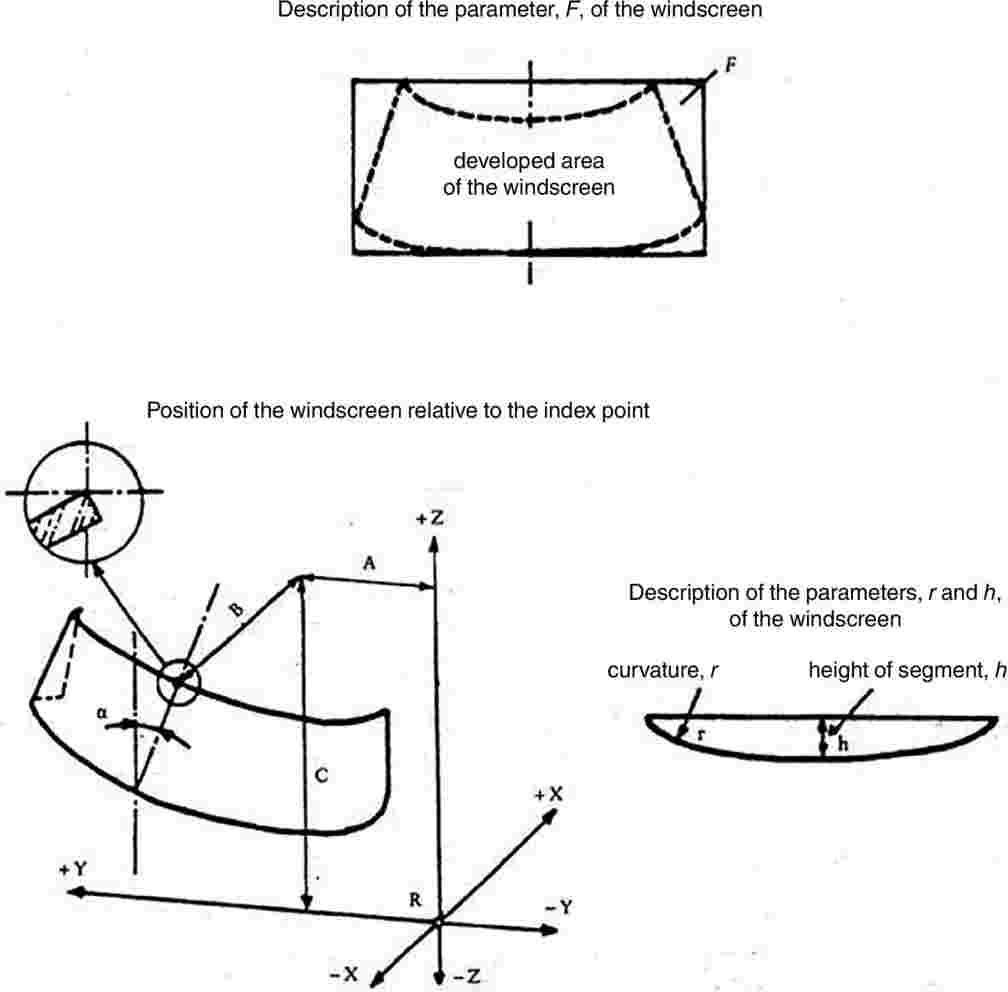
(1) This list must be attached to Appendices 1, 2 (if applicable), 3 and 5 to this Annex.
ANNEX III C
General test conditions
1. FRAGMENTATION TESTS
1.1. The pane of glass to be tested must not be rigidly secured; it may however be fastened on an identical glass pane by means of adhesive tape applied all round the edge.
1.2. To obtain fragmentation, a hammer of about 75 g or some other appliance giving equivalent results is used. The radius of curvature of the point is 0,2 ± 0,05 mm.
1.3. One test must be carried out at each prescribed point of impact.
1.4. An examination must be made of the fragments on photographic contact paper, exposure commencing not more than 10 seconds and terminating not more than three minutes after impact. Only the darkest lines, representing the initial fracture, are taken into consideration. The laboratory must keep photographic reproductions of the fragmentation obtained.
2. BALL-IMPACT TESTS
2.1. 227-g-ball test
2.1.1. Apparatus
2.1.1.1. Hardened-steel ball with a mass of 227 ± 2 g and a diameter of approximately 38 mm.
2.1.1.2. Device for dropping the ball freely from a height to be specified, or a device for giving the ball a velocity equivalent to that obtained by the free fall. When a device to project the ball is used, the tolerance on velocity must be ±1 % of the velocity equivalent to that obtained by the free fall.
2.1.1.3. Supporting fixture, such as that shown in Figure 1, composed of steel frames, with machined borders 15 mm wide, fitting one over the other and faced with rubber gaskets about 3 mm thick and 15 mm wide and of hardness 50 IRHD.
The lower frame rests on a steel box about 150 mm high. The test-piece is held in place by the upper frame, the mass of which is about 3 kg. The supporting frame is welded on to a sheet of steel about 12 mm thick resting on the floor with an interposed sheet of rubber about 3 mm thick and of hardness 50 IRHD.

2.1.2. Test conditions
|
— |
Temperature: 20 ± 5 °C. |
|
— |
Pressure: 860 to 1 060 mbar. |
|
— |
Relative humidity: 60 ± 20 %. |
2.1.3. Test piece
The test piece must be a flat square of side 300 + 10/– 0 mm.
2.1.4. Procedure
Condition the test piece at the specified temperature for at least four hours immediately preceding the test.
Place the test piece in the fixture (2.1.1.3). The plane of the test piece must be perpendicular, within 3°, to the incident direction of the ball.
The point of impact must be within 25 mm of the geometric centre of the test piece for a drop height of 6 m or less, and within 50 mm of the centre of the test piece for a drop height greater than 6 m. The ball must strike that face of the test piece which represents the outside face of the safety-glass pane when mounted on the vehicle. The ball is allowed to make only one impact.
2.2. 2 260-g-ball test
2.2.1. Apparatus
2.2.1.1. Hardened-steel ball with a mass of 2 260 ± 20 g and a diameter of approximately 82 mm.
2.2.1.2. Device for dropping the ball freely from a height to be specified, or a device for giving the ball a velocity equivalent to that obtained by the free fall. When a device to project the ball is used, the tolerance on velocity must be ±1 % of the velocity equivalent to that obtained by the free fall.
2.2.1.3. The supporting fixture is as shown in Figure 1 and identical with that described in point 2.1.1.3.
2.2.2. Test conditions
|
— |
Temperature: 20 ± 5 °C. |
|
— |
Pressure: 860 to 1 060 mbar. |
|
— |
Relative humidity: 60 ± 20 %. |
2.2.3. Test piece
The test piece must be a flat square of side 300 + 10/– 0 mm or cut out from the flattest part of a windscreen or other curved pane of safety glass.
Alternatively, the whole windscreen or other curved pane of safety glass may be tested. In this case care must be taken to ensure adequate contact between the safety-glass pane and the support.
2.2.4. Procedure
Condition the test piece at the specified temperature for at least four hours immediately preceding the test.
Place the test piece in the fixture (2.1.1.3). The plane of the test piece must be perpendicular, within 3°, to the incident direction of the ball.
In the case of glass-plastic glazing the test piece is clamped to the support.
The point of impact must be within 25 mm of the geometric centre of the test piece. The ball must strike that face of the test piece which represents the inward face of the safety-glass pane when the latter is mounted on the vehicle. The ball is allowed to make only one impact.
3. HEADFORM TEST
3.1. Apparatus
3.1.1. Headform weight with a spherical or semi-spherical headform made of laminated hardwood covered with replaceable felt and with or without a cross-beam made of wood. There is a neck-shaped intermediate piece between the spherical part and the cross-beam and a mounting rod on the other side of the cross-beam.
The dimensions are in accordance with Figure 2.
The total mass of the apparatus is 10 ± 0,2 kg.
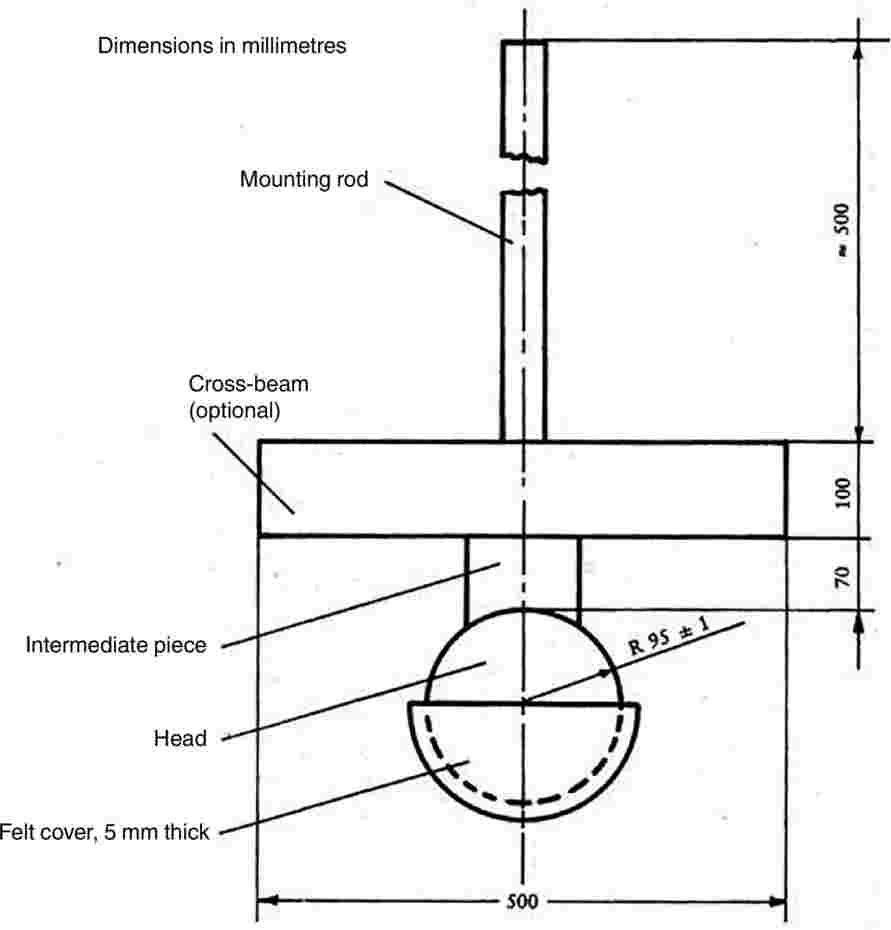
3.1.2. Device for dropping the headform weight freely from a height to be specified, or device for giving the weight a velocity equivalent to that obtained by the free fall.
When a device to project the headform weight is used, the tolerance on velocity must be ±1 % of the velocity equivalent to that obtained by the free fall.
3.1.3. Supporting fixture, as shown in Figure 3, for testing flat test pieces. The fixture is composed of two steel frames, with machined borders 50 mm wide, fitting one over the other and faced with rubber gaskets about 3 mm thick and 15 ± 1 mm wide and a hardness 70 IRHD.
The upper frame is held pressed against the lower frame by at least eight bolts.
3.2. Test conditions
3.2.1. Temperature: 20 ± 5 °C.
3.2.2. Pressure: 860 to 1 060 mbar.
3.2.3. Relative humidity: 60 ± 20 %.

3.3. Procedure
3.3.1. Test on a flat test piece
The flat test piece, having a length of 1 100 + 5/– 2 mm and a width of 500 + 5/– 2 mm is kept at a constant temperature of 20 ± 5 °C for at least four hours immediately preceding the test. Fix the test piece in the supporting frames (3.1.3); tighten the bolts so as to ensure that the movement of the test piece during the test does not exceed 2 mm. The plane of the test piece must be substantially perpendicular to the incident direction of the weight. The weight must strike the test piece within 40 mm of its geometric centre on that face which represents the inward face of the safety-glass pane when the latter is mounted on the vehicle, and be allowed to make only one impact.
The impact surface of the felt cover is to be replaced after 12 tests.
3.3.2. Tests on a complete windscreen (used only for a drop height of less than or equal to 1,5 m)
Place the windscreen freely on a support with an interposed strip of rubber of hardness 70 IRHD and thickness about 3 mm, the width of contact over the whole perimeter being about 15 mm. The support consists of a rigid piece corresponding to the shape of the windscreen so that the headform weight strikes the internal surface. If necessary, the windscreen is clamped to the support by appropriate means. The support must rest on a rigid stand with an interposed sheet of rubber of hardness 70 IRHD and thickness about 3 mm.
The surface of the windscreen must be substantially perpendicular to the incident direction of the headform weight.
The headform weight must strike the windscreen at a point within 40 mm of its geometric centre on that face which represents the inward face of the safety glass pane when the latter is mounted on the vehicle, and be allowed to make only one impact.
The impact surface of the felt cover is to be replaced after 12 tests.
4. ABRASION TEST
4.1. Apparatus
4.1.1. Abrading instrument (1), shown diagrammatically in Figure 4 and consisting of:
|
— |
a horizontal turntable, with centre clamp, which revolves counter-clockwise at 65 to 75 rev/min, and
|
|
— |
two weighted parallel arms each carrying a special abrasive wheel freely relating on a ball-bearing horizontal spindle; each wheel rests on the test specimen under the pressure exerted by a mass of 500 g. |
The turntable of the abrading instrument must rotate regularly, substantially in one plane (the deviation from this plane must not be greater than ±0,05 mm at a distance of 1,6 mm from turntable periphery). The wheels must be mounted in such a way that when they are in contact with the rotating test piece they rotate in opposite directions so as to exert, twice during each rotation of the test piece, a compressive and abrasive action along curved lines over an annular area of about 30 cm2.
4.1.2. Abrasive wheels (2), each 45 to 50 mm in diameter and 12,5 mm thick, composed of a special finely screened abrasive embedded in a medium-hard rubber. The wheels must have a hardness of 72 ± 5 IRHD, as measured at four points equally spaced on the centre line of the abrading surface, the pressure being applied vertically along a diameter of the wheel and the readings being taken 10 seconds after full application of the pressure.
The abrasive wheels must be prepared for use by very slow rotation against a sheet of flat glass to ensure that their surface is completely even.
4.1.3. Light source consisting of an incandescent lamp with its filament contained within a parallelepiped measuring 1,5 mm × 1,5 mm × 3 mm. The voltage at the lamp filament must be such that the colour temperature is 2 856 K ± 50 K. The voltage must be stabilised within ± 1/1 000. The instrument used to check the voltage must be of appropriate accuracy.
4.1.4. Optical system consisting of a lens with a focal length, ƒ, of at least 500 mm and corrected for chromatic aberrations. The full aperture of the lens must not exceed ƒ/20. The distance between the lens and the light source is adjusted in order to obtain a light beam which is substantially parallel. A diaphragm is inserted to limit the diameter of the light beam to 7 mm ± 1 mm. This diaphragm must be situated at a distance of 100 ± 50 mm from the lens on the side remote from the light source.
4.1.5. Equipment for measuring scattered light (see Figure 5), consisting of a photoelectric cell with an integrating sphere 200 to 250 mm in diameter. The sphere is equipped with entrance and exit ports for the light. The entrance port must be circular and have a diameter at least twice that of the light beam. The exit port of the sphere is provided with either a light trap or a reflectance standard, according to the procedure as described in point 4.4.3 below. The light trap absorbs all the light when no test piece is inserted in the light beam.
The axis of the light beam must pass through the centre of the entrance and exit ports. The diameter, b, of the light-exit port must be equal to 2a · tan 4°, where a is the diameter of the sphere.
The photoelectric cell must be mounted in such a way that it cannot be reached by light coming directly from the entrance port or from the reflectance standard.
The surfaces of the interior of the integrating sphere and the reflectance standard must be of substantially equal reflectance and matt and non-selective. The output of the photoelectric cell must be linear within ±2 % over the range of luminous intensities used.
The design of the instrument must be such that there is no galvanometer deflection when the sphere is dark. The whole apparatus must be checked at regular intervals by means of calibration standards of defined haze. If haze measurements are made using equipment or methods differing from those defined above, the results must be corrected, if necessary, to bring them into agreement with those obtained by the apparatus described above.

4.2. Test conditions
4.2.1. Temperature: 20 ± 5 °C.
4.2.2. Pressure: 860 to 1 060 mbar.
4.2.3. Relative humidity: 60 ± 20 %.
4.3. Test pieces
The test pieces must be flat squares whose sides measure 100 mm having both surfaces substantially plane and parallel and if necessary having a fixing hole 6,4 + 0,2/– 0 mm in diameter drilled in the centre.
4.4. Procedure
The abrasion test is carried out on that surface of the test piece which represents the outside face of the safety-glass pane when the latter is mounted on the vehicle and also on the inward face in the case of a glass pane with a plastic coating.
4.4.1. Immediately before and after the abrasion, clean the test pieces in the following manner:
|
(a) |
wipe with a linen cloth under clean running water; |
|
(b) |
rinse with distilled or demineralised water; |
|
(c) |
blow dry with oxygen or nitrogen; |
|
(d) |
remove possible traces of water by dabbing softly with a damp linen cloth. If necessary, dry by pressing lightly between two linen cloths. |
Any treatment with ultrasonic equipment must be avoided. After cleaning, the test pieces must be handled only by their edges and stored to prevent damage to, or contamination of, their surfaces.
4.4.2. Condition the test pieces for a minimum time of 48 hours at a temperature of 20 ± 5 °C and a relative humidity of 60 ± 20 %.
4.4.3. Immediately place the test piece against the entrance port of the integrating sphere. The angle between the normal (perpendicular) to the surface of the test piece and the axis of the beam must not exceed 8°.
Take four readings as indicated in the following table:
|
Reading |
With test piece |
With light trap |
With reflectance standard |
Quantity represented |
|
T1 |
No |
No |
Yes |
Incident light |
|
T2 |
Yes |
No |
Yes |
Total light transmitted by test piece |
|
T3 |
No |
Yes |
No |
Light scattered by instrument |
|
T4 |
Yes |
Yes |
No |
Light scattered by instrument and test piece |
Repeat readings T1, T2, T3 and T4 with other specified positions of the test piece to determine uniformity.
Calculate the total transmittance Tt = T2/T1.
Calculate the diffuse transmittance Td as follows:
Td = (T4 – T3(T2/T1))/T1
Calculate the percentage haze, or light, or both, scattered, as follows:
(Td/Tt) × 100 %
Measure the initial haze of the test piece at a minimum of four equally spaced points in the unabraded area in accordance with the formula above. Average the results for each test piece. In lieu of the four measurements, an average value may be obtained by rotating the piece uniformly at 3 rev/sec or more.
For each safety-glass pane, carry out three tests with the same kind. Use the haze as a measure of the subsurface abrasion, after the test piece has been subjected to the abrasion test.
Measure the light scattered by the abraded track at a minimum of four equally spaced points along the track in accordance with the formula above. Average the results for each test piece. In lieu of the four measurements, an average value may be obtained by rotating the piece uniformly at 3 rev/sec or more.
4.5. The abrasion test is to be carried out only at the discretion of the laboratory conducting the test with due regard to the information already at its disposal. Except for glass-plastic materials, in the case of changes in the interlayer or material thickness, for example, further testing is normally not necessary.
4.6. Indices of difficulty of the secondary characteristics
No secondary characteristics are involved.
5. HIGH-TEMPERATURE TEST
5.1. Procedure
Heat to 100 °C three test samples or three test pieces of at least 300 mm × 300 mm taken by the laboratory from three windscreens or three glass panes other than windscreens, as appropriate, one of whose dimensions corresponds to the upper edge of the pane.
Maintain this temperature for a period of two hours, then allow the test sample(s) to cool to room temperature. If the safety-glass pane has both external surfaces of inorganic material, the test may be carried out by immersing the test sample vertically in boiling water for the specified period of time, care being taken to avoid undue thermal shock. If specimens are cut from windscreens, one edge of each such test specimen shall be part of an edge of the windscreen.
5.2. Indices of difficulty of the secondary characteristics
|
|
Colourless |
Tinted |
|
Colouring of the interlayer: |
1 |
2 |
The other secondary characteristics are not involved.
5.3. Interpretation of results
5.3.1. The test for resistance to high temperature is considered to give a positive result if bubbles or other defects are not formed more than 15 mm from an uncut edge or 25 mm from a cut edge of the test piece or sample or more than 10 mm from any cracks which may occur during the test.
A set of test pieces or samples submitted for component type-approval are considered satisfactory from the point of view of the high-temperature resistance test if either of the following conditions is fulfilled:
5.3.2.1. all the tests give a satisfactory result, or
5.3.2.2. one test having given an unsatisfactory result, a further series of tests carried out on a new set of test pieces or samples gives satisfactory results.
6. RESISTANCE-TO-RADIATION TEST
6.1. Test method
6.1.1. Apparatus
6.1.1.1. Radiation source consisting of a medium-pressure mercury-vapour arc lamp with a tubular quartz bulb of ozone-free type; the bulb axis is vertical. The nominal dimensions of the lamp are 360 mm in length by 9,5 mm in diameter. The arc length is 300 ± 4 mm. The lamp must be operated at 750 ± 50 W.
Any other source of radiation which produces the same effects as the lamp specified above may be used. To check that the effects of another source are the same, a comparison is made by measuring the amount of energy emitted within a wavelength range of 300 to 450 nm, all other wavelengths being removed by the use of suitable filters. The alternative source is then used with these filters.
In the case of safety-glass panes for which there is no satisfactory correlation between this test and the conditions of use it will be necessary to review the test conditions.
6.1.1.2. Power supply transformer and capacitor capable of supplying to the lamp (6.1.1.1) a starting peak-voltage of 1 100 V minimum and an operating voltage of 500 ± 50 V.
6.1.1.3. Device for mounting and rotating the test specimens at 1 to 5 rev/min about the centrally located radiation source in order to ensure even exposure.
6.1.2. Test pieces
6.1.2.1. The size of the test pieces is 76 mm × 300 mm.
6.1.2.2. The test pieces are cut by the laboratory from the upper part of the panes in such a way that:
|
— |
in the case of glass panes other than windscreens the upper edge of the test pieces coincides with the upper edge of the panes, |
|
— |
in the case of windscreens the upper edge of the test pieces coincides with the upper limit of the zone in which regular transmittance is to be checked and determined in accordance with point 9.1.2.2 of this Annex. |
6.1.3. Procedure
Check the regular light transmittance, determined in accordance with points 9.1.1 to 9.1.2 of this Annex, of three test samples before exposure. Protect a portion of each sample from the radiation, and then place the sample in the test apparatus 230 mm from and parallel lengthwise to the lamp axis. Maintain the temperature of the samples at 45 ± 5 °C throughout the test. That face of each test sample which would constitute a grazed exterior part of the tractor must face the lamp. For the type of lamp specified in point 6.1.1.1 the exposure time is 100 hours.
After exposure, measure the regular light transmittance again in the exposed area of each sample.
6.1.4. Each test piece or sample (three in total) is subjected, in accordance with the procedure above, to radiation such that the radiation on each point of the test piece or sample produces on the interlayer used the same effect as that which would be produced by solar radiation of 1 400 W/m2 for 100 hours.
6.2. Indices of difficulty of the secondary characteristics
|
|
Colourless |
Tinted |
|
Colouring of glass |
2 |
1 |
|
Colouring of interlayer |
1 |
2 |
The other secondary characteristics are not involved.
6.3. Interpretation of results
The test for resistance to radiation is deemed to have given a positive result if the following conditions are fulfilled:
the total light transmittance measured in accordance with points 9.1.1 to 9.1.2 of this Annex does not fall below 95 % of the original value before irradiation and, in any case does not fall below:
6.3.1.1.1. 70 % in the case of glass panes other than windscreens which must meet the requirements concerning the driver's field of vision in all directions;
6.3.1.1.2. 75 % in the case of windscreens, within the zone in which regular transmittance is to be checked, as defined in point 9.1.2.2 below.
6.3.1.2. The test piece or sample may however show a slight coloration after irradiation when examined against a white background, but no other defect may be apparent.
A set of test pieces or samples submitted for component type-approval is considered satisfactory from the point of view of the resistance to radiation test if one of the following conditions is fulfilled:
6.3.2.1. all tests give a satisfactory result, or
6.3.2.2. one test having given an unsatisfactory result, a further series of tests carried out on a new set of test pieces or samples gives satisfactory results.
7. RESISTANCE-TO-HUMIDITY TEST
7.1. Procedure
Keep three test samples or three test pieces at least 300 mm × 300 mm square vertically for two weeks in a closed container in which the temperature is maintained at 50 ± 2 °C and the relative humidity at 95 % ± 4 % (3).
Test pieces are prepared in such a way that:
|
— |
one edge of each test piece is part of an original edge of the windscreen, |
|
— |
should several test pieces be tested at the same time, adequate spacing must be provided between them. |
Precautions must be taken to prevent condensation from the walls or ceiling of the test chamber from falling on the test specimens.
7.2. Indices of difficulty of the secondary characteristics
|
|
Colourless |
Tinted |
|
Colouring of interlayer |
1 |
2 |
The other secondary characteristics are not involved.
7.3. Interpretation of results
7.3.1. Safety-glass panes are deemed to be satisfactory from the point of view of resistance to humidity if no significant change is observed more than 10 mm from the uncut edges or more than 15 mm from the cut edges, following a stay of two hours in the ambient atmosphere by ordinary and treated laminated glass, and of 48 hours in the ambient atmosphere by plastic-coated glass panes and plastic glazing.
A set of test pieces or samples submitted for component type-approval is considered satisfactory from the point of view of the resistance to humidity test if one of the following conditions is fulfilled:
7.3.2.1. all the tests give a satisfactory result;
7.3.2.2. one test having given an unsatisfactory result, a further series of tests carried out on a new set of samples gives satisfactory results.
8. TESTING OF RESISTANCE TO CHANGES IN TEMPERATURE
8.1. Test method
Two 300 × 300 mm test pieces are placed in an enclosed chamber for six hours at a temperature of –40 ± 5 °C; they are then placed in the ambient air at a temperature of 23 ±°C for an hour, or until the test piece has reached a stable temperature. They are then placed in an air flow at a temperature of 72 ± 2 °C for three hours. The test pieces are then examined after they have been returned to the ambient air at 23 ± 2 °C and cooled to that temperature.
8.2. Index of difficulty of the secondary characteristics
|
|
Colourless |
Tinted |
|
Colouring of plastic interlayer or coating |
1 |
2 |
No other secondary characteristics are involved.
8.3. Interpretation of results
The test of resistance to changes in temperature is considered to have given a positive result if the test pieces display no cracking, opacification, exfoliation or other obvious deterioration.
9. OPTICAL QUALITIES
9.1. Light transmission test
9.1.1. Apparatus
9.1.1.1. Light source consisting of an incandescent lamp having its filament contained within a parallelepiped measuring 1,5 mm × 1,5 mm × 3 mm. The voltage at the lamp filament must be such that the colour temperature is 2 856 K ± 50 K. This voltage is stabilised within ± 1/1 000. The instrument used to check the voltage must be of appropriate accuracy.
9.1.1.2. Optical system consisting of a lens with a focal length of at least 500 mm and corrected for chromatic aberrations. The full aperture of the lens must not exceed f/20. The distance between the lens and the light source must be so adjusted as to obtain a light beam which is substantially parallel.
A diaphragm is inserted to limit the diameter of the light beam to 7 ± 1 mm. This diaphragm is situated at a distance of 100 ± 50 mm from the lens on the side remote from the light source. The point of measurement is taken at the centre of the light beam.
9.1.1.3. Measuring equipment. The receiver must have a relative spectral sensitivity in substantial agreement with the relative spectral luminous efficiency for the CIE (Commission Internationale de L'Éclairage) standard photometric observer for photoptic vision. The sensitive surface of the receiver is covered with a diffusing medium and must have at least twice the cross-section of the light beam emitted by the optical system. If an integrating sphere is used, the aperture of the sphere must have a cross-sectional area at least twice that of the parallel portion of the beam.
The linearity of the receiver and the associated indicated instrument must be better than 2 % of the effective part of the scale. The receiver must be situated at the axis of the light beam.
9.1.2. Procedure
So adjust the instrument indicating the response of the receiver that it indicates 100 divisions when the safety-glass pane is not inserted in the light path. When no light is falling on the receiver, the instrument must read zero.
Place the safety-glass pane at a distance from the receiver equal to approximately five times the diameter of the receiver. Insert the safety-glass pane between the diaphragm and the receiver and adjust its orientation in such a way that the angle of incidence of the light beam is equal to 0° ± 5°. The regular transmittance is measured on the safety-glass pane, and for every point measured the number of divisions, n, shown on the indicating instrument, is read. The regular transmittance τr is equal to n/100.
9.1.2.1. In the case of windscreens, alternative test methods may be applied using either a test sample cut from the flattest part of a windscreen or a specially prepared flat square with material and thickness characteristics identical to those of the actual windscreen, the measurements being taken normal (perpendicular) to the glass pane.
9.1.2.2. The test is carried out in the zone I specified in point 9.2.5.2 of this Annex.
9.1.2.3. In the case of tractors for which it is not possible to determine zone I as defined in point 9.2.5.2, the test is carried out in zone I′ as defined in point 9.2.5.3 of this Annex.
9.1.3. Indices of difficulty of the secondary characteristics
|
|
Colourless |
Tinted |
|
Colouring of the glass |
1 |
2 |
|
Colouring of the interlayer (in the case of laminated windscreens) |
1 |
2 |
|
|
not included |
included |
|
Shade and/or obscuration bands |
1 |
2 |
The other secondary characteristics are not involved.
9.1.4. Interpretation of results
9.1.4.1. The regular transmittance measured according to point 9.1.2 in the case of windscreens must not be less than 75 %, and in the case of windows other than windscreens not less than 70 %.
9.1.4.2. In the case of windows situated at points which are not essential to the driver's field of vision (glazed roof, for example) the regular transmittance factor of the light from the pane may be less than 70 %. Windows having a regular light transmittance factor of less than 70 % must be marked with an appropriate symbol.
9.2. Optical-distortion test
9.2.1. Scope
The method specified is a projection method which permits evaluation of the optical distortion of a safety-glass pane.
9.2.1.1. Definitions
9.2.1.1.1. Optical deviation: the angle between the true and the apparent direction of a point viewed through the safety-glass pane, the magnitude of the angle being a function of the angle of incidence of the line of sight, the thickness and inclination of the glass pane, and the radius of curvature at the point of incidence.
9.2.1.1.2. Optical distortion in a direction MM′: the algebraic difference in angular deviation Δα measured between two points M and M′ on the surface of the safety-glass pane, the distance between the two points being such that their projections in a plane at right angles to the direction of vision are separated by a given distance Δx (see Figure 6).
Anti-clockwise deviation is to be regarded as positive and clockwise deviation as negative.
9.2.1.1.3. Optical distortion at a point M: the optical distortion maximum for all directions MM′ from the point M.
9.2.1.2. Apparatus
This method entails the projection of an appropriate slide (raster) on to the display screen through the safety-glass pane being tested. The change caused in the shape of the projected image by the insertion of the safety-glass pane in the line of light provides a measure of the distortion. The apparatus comprises the following items, arranged as shown in Figure 9.

|
Notes: |
Δα = α1 – α2, |
i.e. the optical distortion in the direction MM′. |
|
|
Δx = MC |
i.e. the distance between two straight lines parallel to the direction of vision and passing through the points M and M′. |

9.2.1.2.1. Projector, of good quality, with a high-intensity point light source, having for example the following characteristics:
|
— |
focal length at least 90 mm, |
|
— |
aperture approximately 1/2,5, |
|
— |
150 W quartz halogen lamp (if used without a filter), |
|
— |
250 W quartz halogen lamp (if a green filter is used). |

The projector is shown schematically in Figure 7. A diaphragm of 8 mm diameter is positioned approximately 10 mm from the front lens.
9.2.1.2.2. Slides (rasters) consisting, for example, of an array of bright circular shapes on a dark background (see Figure 8). The slide must be of sufficiently high quality and contrast to enable measurement to be carried out with an error of less than 5 %. In the absence of the safety-glass pane to be examined, the dimensions of the circular shapes must be such that when the circular shapes are projected they form an array of circles of diameter ((R1 + R2)/R1) Δx where Δx = 4 mm (see Figures 6 and 9).

9.2.1.2.3. Support stand, preferably one permitting vertical and horizontal scanning, as well as rotation of the safety-glass pane.
9.2.1.2.4. Checking template, for measuring changes in dimensions where a rapid assessment is required. A suitable design is shown in Figure 10.
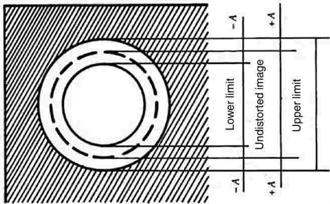
9.2.1.3. Procedure
9.2.1.3.1. General
Mount the safety-glass pane on the support stand (9.2.1.2.3) at the designated rake angle. Project the test image through the area being examined. Rotate the safety-glass pane or move it either horizontally or vertically in order to examine the whole of the specified area.
9.2.1.3.2. Assessment using a checking template
Where a rapid assessment with a possible margin of error of up to 20 % is sufficient, calculate the value of A (see Figure 10) from the limit value ΔαL for the change in deviation and the value of R 2, the distance from the safety-glass pane to the display screen:
A = 0,145 ΔαL· R2
The relationship between the change in diameter of the projected image Δd and the change in angular deviation Δα is given by:
Δd = 0,29 Δα · R2
where:
|
Δd |
is expressed in millimetres, |
|
A |
is expressed in millimetres, |
|
ΔαL |
is expressed in minutes of arc, |
|
Δα |
is expressed in minutes of arc, and |
|
R2 |
is expressed in metres. |
9.2.1.3.3. Measurement using a photoelectric device
Where a precise measurement with a possible margin of error of less than 10 % of the limit value is required, measure Δd on the projection axis, the value of the spot width being taken at the point where the luminance is 0,5 times the maximum spot luminance value.
9.2.1.4. Expression of results
Evaluate the optical distortion of the safety-glass panes by measuring Δd at any point of the surface and in all directions in order to find Δd max.
9.2.1.5. Alternative method
In addition, a strioscopic technique is permitted as an alternative to the projection techniques, provided that the accuracy of the measurements given in points 9.2.1.3.2 and 9.2.1.3.3 is maintained.
9.2.1.6. The distance Δx must be 4 mm.
9.2.1.7. The windscreen must be mounted at the same rake angle as on the tractor.
9.2.1.8. The projection axis in the horizontal plane must be maintained approximately normal to the trace of the windscreen in that plane.
The measurements are performed in zone I as defined in point 9.2.5.2 of this Annex.
9.2.2.1. In the case of tractors for which it is not possible to determine zone I as defined in point 9.2.5.2 of this Annex, the test is carried out in zone I′, as defined in point 9.2.5.3 of this Annex.
9.2.2.2. Tractor type
The test must be repeated if the windscreen is to be mounted on a tractor of a type which has a different forward field of vision from that of the tractor type for which the windscreen has already been approved.
9.2.3. Indices of difficulty of the secondary characteristics
9.2.3.1. Nature of the material
|
Polished (plate) glass |
Float glass |
Sheet glass |
|
1 |
1 |
2 |
9.2.3.2. Other secondary characteristics
No other secondary characteristics are involved.
9.2.4. Number of samples
Four samples must be submitted for testing.
9.2.5. Definition of the zone of vision of tractor windscreens
The zone of vision is defined on the basis of:
9.2.5.1.1. the reference point as defined in point 1.2 of Annex I to Directive 2008/2/EC. This point is designated as O below;
9.2.5.1.2. the straight line OQ which is the horizontal straight line passing through the reference point and perpendicular to the median longitudinal plane of the tractor;
9.2.5.2. zone I is the windscreen zone determined by the intersection of the windscreen with the four planes defined below:
|
P1 |
— |
a vertical plane passing through O and forming an angle of 15° to the left of the median longitudinal plane of the tractor, |
|
P2 |
— |
a vertical plane symmetrical to P1 about the median longitudinal plane of the tractor. If this is not possible (in the absence of a symmetrical median longitudinal plane, for instance) P2 is the plane symmetrical to P1 about the longitudinal plane of the tractor passing through the reference point, |
|
P3 |
— |
a plane passing through the straight line OQ and forming an angle of 10° above the horizontal plane, |
|
P4 |
— |
a plane passing through the straight line OQ and forming an angle of 8° below the horizontal plane. |
9.2.5.3. In the case of tractors for which it is not possible to determine zone I, as defined in point 9.2.5.2 of this Annex, zone I′ consists of the whole surface of the windscreen.
9.2.6. Interpretation of results
A type of windscreen is considered satisfactory as regards optical distortion if, in the four samples submitted for testing, optical distortion does not exceed a maximum value of 2′ of an arc in either zone I or zone I′.
9.2.6.1. No measurement must be performed within a 100 mm-wide peripheral zone.
9.2.6.2. In the case of divided windscreens, no measurement is performed within a band 35 mm in width, starting from the edge of the pane, which may be adjacent to the screen divider.
9.3. Secondary-image separation test
9.3.1. Scope
Two test methods are recognised:
|
— |
target test, and |
|
— |
collimation telescope test. |
These test methods may be used for component type-approval, quality-control or product-evaluation purposes, as appropriate.
9.3.1.1. Target test
9.3.1.1.1. Apparatus
This method involves viewing an illuminated target through the safety-glass pane. The target may be designed in such a way that the test can be carried out on a simple go/no go basis.
The target must preferably be of one of the following types:
|
(a) |
an illuminated ring target whose outer diameter, D, subtends an angle of η minutes of arc at a point situated at x metres (Figure 11a); or |
|
(b) |
an illuminated ring and spot target whose dimensions are such that the distance, D, from a point on the edge of the spot to the nearest point on the inside of the circle subtends an angle of η minutes of arc at a point situated at x metres (Figure 11b); |
where:
|
η |
is the limit value of secondary-image separation, |
|
x |
is the distance from the safety-glass pane to the target (not less than 7 m), |
|
D |
is given by the formula: |
D = x · tan η
The illuminated target consists of a light box, approximately 300 mm × 300 mm × 150 mm, whose front is most conveniently constructed of glass masked with opaque black paper or coated with matt black paint. The box is illuminated by a suitable light source. The inside of the box is coated with matt white paint. It may be convenient to use other forms of target, such as that shown in Figure 14. It is also acceptable to replace the target system by a projection system and to view the resulting images on a screen.
9.3.1.1.2. Procedure
Mount the safety-glass pane at the specified rake angle on a suitable stand in such a way that the observation is carried out in the horizontal plane passing through the centre of the target.
The light box must be viewed, in a dark or semi-dark room, through each part of the area being examined, in order to detect the presence of any secondary image associated with the illuminated target. Rotate the safety-glass pane as necessary to ensure that the correct direction of view is maintained. A monocular may be used for viewing.
9.3.1.1.3. Expression of results
Determine whether:
|
— |
when target (a) (see Figure 11a) is used, the primary and secondary image of the circle separate, i.e. whether the limit value of η is exceeded, or |
|
— |
when target (b) (see Figure 11b) is used, the secondary image of the spot shifts beyond the point of tangency with the inside edge of the circle, i.e. whether the limit value of η is exceeded. |
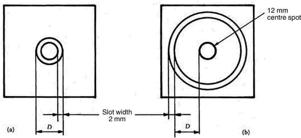
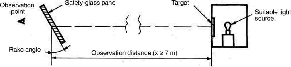

9.3.1.2. Collimation telescope test
If necessary, the procedure described in this point is applied.
9.3.1.2.1. Apparatus
The apparatus comprises a collimator and a telescope and may be set up in accordance with Figure 13. However, any equivalent optical system may be used.
9.3.1.2.2. Procedure
The collimation telescope forms at infinity the image of a polar-coordinate system with a bright point at its centre (see Figure 14). In the focal plane of the observation telescope, a small opaque spot with a diameter slightly larger than that of the projected bright point is placed on the optical axis, thus obscuring the bright point.
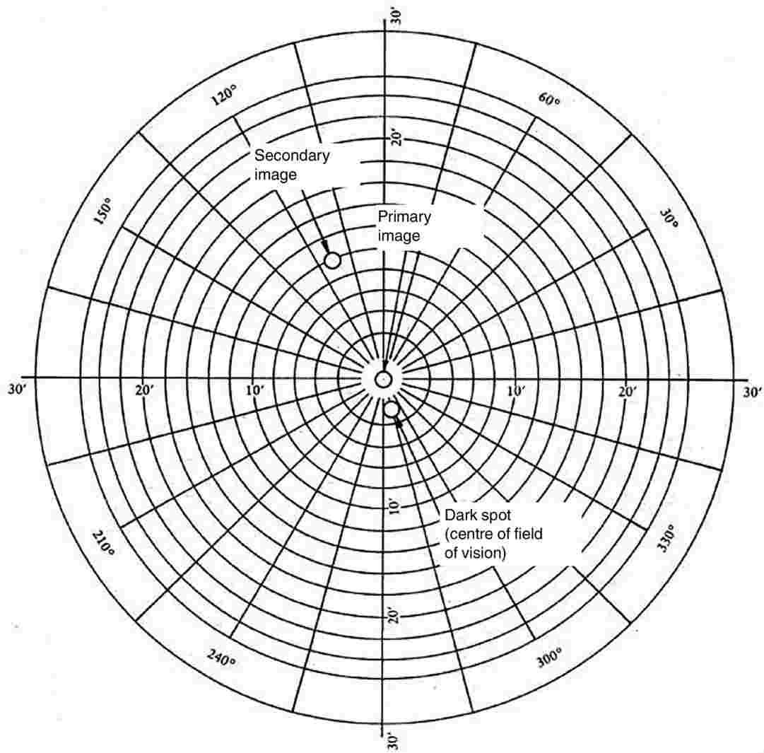
When a test piece which exhibits a secondary image is placed between the telescope and the collimator, a second, less bright point appears at a certain distance from the centre of the polar-coordinate system. The secondary-image separation can be read out as the distance between the points seen through the observation telescope (see Figure 14). (The distance between the dark spot and the bright point at the centre of the polar-coordinate system represents the optical deviation.)
9.3.1.2.3. Expression of results
The safety-glass pane is first examined by a simple scanning technique to establish the area giving the strongest secondary image. That area is then examined by the collimator telescope system at the appropriate angle of incidence. The maximum secondary-image separation is measured.
9.3.1.3. The direction of observation in the horizontal plane must be maintained approximately normal to the trace of the windscreen in that plane.
The measurements are performed according to tractor category in the zones defined in point 9.2.2.
9.3.2.1. Tractor type
The test must be repeated if the windscreen is to be mounted on a tractor of a type which has a forward field of vision different from that of the tractor for which the windscreen has already been approved.
9.3.3. Indices of difficulty of the secondary characteristics
9.3.3.1. Nature of the material
|
Polished (plate) glass |
Float glass |
Sheet glass |
|
1 |
1 |
2 |
9.3.3.2. Other secondary characteristics
No other secondary characteristics are involved.
9.3.4. Number of samples
Four samples must be submitted for testing.
9.3.5. Interpretation of results
A type of windscreen is considered satisfactory as regards secondary-image separation if, in the four samples submitted for testing, separation of the primary and secondary image does not exceed a maximum value of 15′ of an arc.
9.3.5.1. No measurement must be carried out in a 100 mm-wide peripheral zone.
9.3.5.2. In the case of divided windscreens no measurement may be performed within a band 35 mm in width, starting from the edge of the pane, which may be adjacent to the screen divider.
9.4. Identification of colours test
When a windscreen is tinted in the zones defined in point 9.2.5.2 or point 9.2.5.3, four windscreens are tested for identifiability of the following colours:
|
— |
white, |
|
— |
selective yellow, |
|
— |
red, |
|
— |
green, |
|
— |
blue, |
|
— |
amber. |
10. FIRE-RESISTANCE TEST
10.1. Purpose and scope of application
This method enables the horizontal burning rate of materials used in the occupant compartment of tractors after exposure to a small flame to be determined. This method permits testing of materials and components of a tractor's interior equipment individually or in combination up to a thickness of 15 mm. It is used to judge the uniformity of production lots of such materials with respect to their burning behaviour. Because of the many differences between the real-world situation (application and orientation within a tractor; conditions of use; ignition source, etc.) and the precise test conditions prescribed herein, this method cannot be considered as suitable for evaluation of all true in-tractor burning characteristics.
10.2. Definitions
10.2.1. Burning rate: the quotient of the burnt distance measured according to this method and the time taken to burn that distance.
It is expressed in millimetres per minute.
10.2.2. Composite material: a material composed of several layers of similar or different materials intimately held together at their surface by cementing, bonding, cladding, welding, etc. When different materials are connected together intermittently (for example, by sewing, high-frequency welding, riveting), then in order to permit the preparation of individual samples in accordance with point 10.5 such materials are not considered as composite materials.
10.2.3. Exposed side: the side which is facing towards the occupant compartment (passenger compartment) when the material is mounted in the tractor.
10.3. Principle
A sample is held horizontally in a U-shaped holder and is exposed to the action of a defined low-energy flame for 15 seconds in a combustion chamber, the flame acting on the free end of the sample. The test determines whether and when the flame is extinguished or the time which the flame requires to proceed over a measured distance.
10.4. Apparatus
10.4.1. Combustion chamber (Figure 15), preferably of stainless steel, having the dimensions given in Figure 16. The front of the chamber contains a flame-resistant observation window, which may cover the entire front and which can be constructed as an access panel.
The bottom of the chamber has vent holes, and the top has a vent slot all around. The combustion chamber is placed on four feet, 10 mm high.
The chamber may have a hole at one end for the introduction of the sample holder containing the sample; in the opposite end, a hole is provided for the gas supply line. Melted material is caught in a pan (see Figure 17) which is placed on the bottom of the chamber between vent holes without covering any vent hole area.
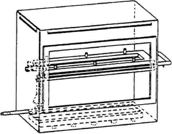
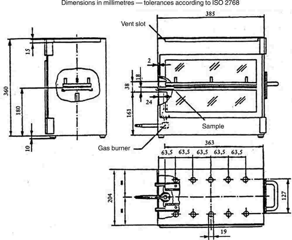

10.4.2. Sample holder, consisting of two U-shaped metal plates or frames of corrosion-proof material. Dimensions are given in Figure 18.
The lower plate is equipped with pins and the upper one with corresponding holes, in order to ensure a consistent holding of the sample. The pins also serve as measuring points at the beginning and end of the burning distance.
A support is provided in the form of heat-resistant wires 0,25 mm in diameter spanning the frame at 25 mm intervals over the bottom U-shaped frame (see Figure 19).


The plane of the lower side of samples must be 178 mm above the floor plate. The distance of the front edge of the sample holder from the end of the chamber must be 22 mm; the distance of the longitudinal sides of the sample holder from the sides of the chamber must be 50 mm (all inside dimensions). (See Figures 15 and 16.)
10.4.3. Gas burner. The small ignition source is provided by a Bunsen burner having an inside diameter of 9,5 mm. It is so located in the test cabinet that the centre of its nozzle is 19 mm below the centre of the bottom edge of the open end of the sample (see Figure 16).
10.4.4. Test gas. The gas supplied to the burner must have a calorific value of about 38 MJ/m3 (for example natural gas).
10.4.5. Metal comb, at least 110 mm in length, with seven or eight smooth rounded teeth per 25 mm.
10.4.6. Stop-watch, accurate to 0,5 second.
10.4.7. Fume cupboard. The combustion chamber may be placed in a fume cupboard assembly provided that the latter's internal volume is at least 20 times, but not more than 110 times, greater than the volume of the combustion chamber and provided that no single height, width, or length dimension of the fume cupboard is greater than 2,5 times either of the other two dimensions.
Before the test, the vertical velocity of the air through the fume cupboard is measured 100 mm forward of and to the rear of the ultimate site of the combustion chamber. It must be between 0,10 and 0,30 m/s in order to avoid possible discomfort to the operator from combustion products. It is possible to use a fume cupboard with natural ventilation and an appropriate air velocity.
10.5. Samples
10.5.1. Shape and dimensions
The shape and dimensions of samples are given in Figure 20. The thickness of the sample corresponds to the thickness of the product to be tested. It must not be more than 13 mm. When sample taking so permits, the sample must have a constant section over its entire length. When the shape and dimensions of a product do not permit taking a sample of the given size, the following minimum dimensions must be observed:
|
(a) |
for samples having a width of 3 to 60 mm, the length must be 356 mm. In this case the material is tested over the product's width; |
|
(b) |
for samples having a width of 60 to 100 mm, the length must be at least 138 mm. In this case the potential burning distance corresponds to the length of the sample, the measurement starting at the first measuring point; |
|
(c) |
samples less than 60 mm wide and less than 356 mm long, and samples 60 to 100 mm wide and less than 138 mm long, cannot be tested according to the present method, nor can samples less than 3 mm wide. |
10.5.2. Sampling
At least five samples are to be taken from the material under test. In materials having burning rates differing according to the direction of the material (this being established by preliminary tests) the five (or more) samples are to be taken and placed in the test apparatus in such a way that the highest burning rate will be measured. When the material is supplied in set widths, a length of at least 500 mm covering the entire width is cut. From the piece so cut, the samples are to be taken at not less than 100 mm from the edge of the material and at points equidistant from each other.
Samples are to be taken in the same way from finished products when the shape of the product so permits. If the thickness of the product is over 13 mm it must be reduced to 13 mm by a mechanical process applied to the side which does not face the passenger compartment.
Composite materials (see point 10.2.2) are to be tested as if they were homogeneous.
In the case of materials comprising superimposed layers of different composition which are not composite materials, all the layers of material included within a depth of 13 mm from the surface facing towards the passenger compartment are to be tested individually.

10.5.3. Conditioning
The samples are to be conditioned for at least 24 hours, but no more than 7 days, at a temperature of 23 ± 2 °C and a relative humidity of 50 ± 5 %, and maintained under these conditions until immediately prior to testing.
10.6. Procedure
10.6.1. Place samples with napped or tufted surfaces on a flat surface, and comb twice against the nap using the comb (10.4.5).
10.6.2. Place the sample in the sample holder (10.4.2) so that the exposed side faces downwards, towards the flame.
10.6.3. Adjust the gas flame to a height of 30 mm using the mark in the chamber, the air intake of the burner being closed. The flame must burn for at least one minute, for stabilisation, before the first test is started.
10.6.4. Push the sample holder into the combustion chamber so that the end of the sample is exposed to the flame, and after 15 seconds cut off the gas flow.
10.6.5. Measurement of burning time starts at the moment when the foot of the flame passes the first measuring point. Observe the flame propagation on the side (upper or lower) which burns faster.
10.6.6. Measurement of burning time is completed when the flame has come to the last measuring point or when the flame is extinguished before reaching that point. If the flame does not reach the last measuring point, measure the burnt distance up to the point where the flame was extinguished. Burnt distance is the part of the sample destroyed, on the surface or inside, by burning.
10.6.7. If the sample does not ignite or does not continue burning after the burner has been extinguished, or the flame goes out before reaching the first measuring point, so that no burning time is measured, note in the test report that the burning is 0 mm/minute.
10.6.8. When running a series of tests or performing repeat tests, make sure before starting a test that the temperature of the combustion chamber and sample-holder does not exceed 30 °C.
10.7. Calculation
The burning rate, B, in millimetres per minute, is given by the formula:
B = (s/t) × 60
where:
|
s |
is the burnt distance, in millimetres, |
|
t |
is the time, in seconds, taken to burn the distance s. |
10.8. Indices of difficulty of the secondary characteristics
No secondary characteristics are involved.
10.9. Interpretation of results
Plastic-coated (2.3) and plastic safety glazing (2.4) are considered satisfactory from the point of view of burning behaviour (fire resistance) if the burn rate does not exceed 250 mm/minute.
11. TESTING OF RESISTANCE TO CHEMICAL AGENTS
11.1. Chemical agents to be used
11.1.1. Non-abrasive soapy solution: 1 % by weight of potassium oleate in de-ionised water.
11.1.2. Window-cleaning product: aqueous solution of isopropanol and dipropylene glycol monomethyl ether, each at a concentration of 5 % to 10 % by weight, and of ammonium hydroxyde at a concentration of 1 % to 5 % by weight.
11.1.3. Non-dilute denatured alcohol: one part by volume of methyl alcohol in 10 parts by volume of ethyl alcohol.
11.1.4. Reference gasoline mixture of 50 % by volume of toluene, 30 % by volume of 2,2,4-trimethylpentane, 15 % by volume of 2,4,4-trimethyl-1-pentane and 5 % by volume of ethyl alcohol.
11.1.5. Reference kerosene: mixture of 50 % by volume of n-octane and 50 % by volume of n-decane.
11.2. Test method
Two 180 × 25 mm test pieces are each to be tested with chemical agents as provided for in point 11.1, a new test piece being used for each test and product. After each test the pieces are to be cleaned in accordance with the manufacturer's instruction, and then conditioned for 48 hours at a temperature of 23 ± 2 °C and a relative humidity of 50 ± 5 %. These conditions are to be maintained during the tests. The test pieces are to be completely immersed in the test liquid for one minute, withdrawn and then immediately dried with a (clean) absorbent cotton cloth.
11.3. Indices of difficulty of the secondary characteristics
|
|
Colourless |
Tinted |
|
Colouring of the plastic interlayer, or coating |
1 |
2 |
No secondary characteristic is involved.
11.4. Interpretation of the results
11.4.1. The test for resistance to chemical agents is considered to be positive if the test pieces display no softening, stickiness, surface cracking or apparent loss of transparency.
A series of test pieces submitted for component type-approval is considered satisfactory as regards resistance to chemical agents if one of the following conditions has been met:
11.4.2.1. all the tests give satisfactory results;
11.4.2.2. a test having given an unsatisfactory result, a further series of tests must be carried out on a new set of test pieces and give satisfactory results.
(1) A suitable abrading instrument is supplied by Teledyne Taber (United States of America).
(2) Suitable abrasive wheels may be obtained from Teledyne Taber (United States of America).
(3) These test conditions exclude any condensation on the test pieces.
ANNEX III D
Toughened-glass windscreens
1. DEFINITION OF TYPE
Toughened-glass windscreens are deemed to belong to different types if they differ in at least one of the following principal or secondary characteristics.
1.1. The principal characteristics are as follows:
1.1.1. the trade name or mark;
the shape and dimensions.
Toughened-glass windscreens are considered as belonging to one or other of two groups for the purposes of the fragmentation and mechanical-properties tests, i.e.:
1.1.2.1. flat windscreens, and
1.1.2.2. curved windscreens;
1.1.3. the thickness category in which the nominal thickness ‘e’ lies (a manufacturing tolerance of ±0,2 mm being allowed):
|
|
e ≤ 4,5 mm |
||
|
4,5 mm < |
e ≤ 5,5 mm |
||
|
5,5 mm < |
e ≤ 6,5 mm |
||
|
6,5 mm < |
e |
1.2. The secondary characteristics are as follows:
1.2.1. nature of the material (polished (plate) glass, float glass, sheet glass),
1.2.2. colouring (colourless or tinted),
1.2.3. the incorporation or absence of conductors,
1.2.4. the incorporation or absence of obscuration bands.
2. FRAGMENTATION TEST
2.1. Indices of difficulty of the secondary characteristics
2.1.1. Only the nature of the material is involved.
2.1.2. Float glass and sheet glass are considered to have the same index of difficulty.
2.1.3. The fragmentation tests must be repeated on transition from polished (plate) glass to float glass or sheet glass, and vice versa.
2.1.4. The tests must be repeated if obscuration bands other than painted bands are used.
2.2. Number of samples
Six samples from the smallest-developed-area series and six samples from the largest-developed-area series, selected as prescribed in Annex III M, are to be tested.
2.3. Different zones of glass
A toughened-glass windscreen must comprise two main zones, FI and FII. It may also comprise an intermediate zone, FIII.
These zones are as defined below:
2.3.1. zone FI: peripheral zone of fine fragmentation, at least 7 cm wide, all round the edge of the windscreen and including an outer strip 2 cm wide not subjected to assessment;
zone FII: visibility zone of varying fragmentation, always including a rectangular part at least 20 cm high and 50 cm long.
2.3.2.1. The centre of the rectangle is inside a circle having a radius of 10 cm centred on the projection of the reference point.
2.3.2.2. In the case of tractors for which it is not possible to determine the reference point, the position of the visibility zone must be indicated in the test report.
2.3.2.3. The height of the above rectangle may be reduced to 15 cm for windscreens which are less than 44 cm high;
2.3.3. zone FIII: intermediate zone, not more than 5 cm wide, between zones FI and FII.
2.4. Test method
The method used is that described in point 1 of Annex III C.
2.5. Points of impact (see Annex III N, Figure 2)
2.5.1. The points of impact are selected as follows:
point 1: in the central part of zone FII in an area of high or low stress;
point 2: in zone FIII, as near as possible to the vertical plane of symmetry of zone FII;
points 3 and 3′: 3 cm from the edges of one median of the sample; when there is a tong mark, one of the breakage points shall be near the edge bearing the tong mark and the other near the opposite edge;
point 4: at the place where the radius of curvature is smallest on the longest median;
point 5: 3 cm from the edge of the sample at the place where the radius of curvature of the edge is smallest, either to the left or to the right.
2.5.2. A fragmentation test is performed at each of the points 1, 2, 3, 3′, 4 and 5.
2.6. Interpretation of results
A test is deemed to have given a satisfactory result if fragmentation satisfies all the conditions given in points 2.6.1.1, 2.6.1.2 and 2.6.1.3 below.
2.6.1.1. Zone FI
2.6.1.1.1. The number of fragments in any 5 × 5 cm square is not less than 40 nor more than 350; however, in the case of a count of less than 40, if the number of fragments in any 10 × 10 cm square containing the 5 × 5 cm square is not less than 160, this is acceptable.
2.6.1.1.2. For the purposes of the above rule, a fragment extending across a side of a square counts as half a fragment.
2.6.1.1.3. Fragmentation is not checked in a strip 2 cm wide round the edge of the samples, this strip representing the frame of the glass, nor within a radius of 7,5 cm from the point of impact.
2.6.1.1.4. A maximum of three fragments of an area exceeding 3 cm2 is allowed. No two of these fragments must be contained within the same 10 cm diameter circle.
2.6.1.1.5. Elongated fragments may be permitted provided that their ends are not knife-edged and that their length does not exceed 7,5 cm, except in the case provided for in point 2.6.2.2 below. If these elongated fragments extend to the edge of the glass, they must not form an angle of more than 45° with it.
2.6.1.2. Zone FII
2.6.1.2.1. The residual visibility after shattering is checked in the rectangular area defined in point 2.3.2. In that rectangle the aggregate surface area of the fragments of more than 2 cm2 must represent not less than 15 % of the area of the rectangle; however, in the case of windscreens less than 44 cm high, or whose angle of installation is less than 15° from the vertical, the visibility percentage must be equal to 10 % at least of the surface of the corresponding rectangle.
2.6.1.2.2. No fragment must have an area of more than 16 cm2 except in the case provided for in point 2.6.2.2.
2.6.1.2.3. Within a radius of 10 cm from the point of impact, but only in that part of the circle which is included in zone FII, three fragments having an area of more than 16 cm2 but less than 25 cm2 are allowed.
Fragments must be substantially regular in shape and free from points of the type described in point 2.6.1.2.4.1. However, not more than 10 irregular fragments are allowed in any 50 × 20 cm rectangle and not more than 25 over the whole surface of the windscreen.
No such fragment must present a point more than 35 mm long measured in accordance with point 2.6.1.2.4.1.
2.6.1.2.4.1. A fragment is considered as an irregular fragment if it cannot be inscribed in a circle of 40 mm in diameter, if it has at least one point more than 15 mm long when measured from the top of the point to the section whose width is equal to the glazing thickness, and if it has one or more points having a top angle smaller than 40°.
2.6.1.2.5. Fragments of elongated shape are allowed in zone FII as a whole, provided they do not exceed 10 cm in length, except in the case provided for in point 2.6.2.2.
2.6.1.3. Zone FIII
Fragmentation in this zone must have characteristics intermediate between those of the fragmentations respectively allowed for the two neighbouring zones (FI and FII).
A windscreen submitted for component type-approval is considered satisfactory from the point of view of fragmentation if at least one of the following conditions is fulfilled:
2.6.2.1. when all the tests carried out using the points of impact defined in point 2.5.1 have given a satisfactory result;
2.6.2.2. when one test among all those carried out using the points of impact prescribed in point 2.5.1 has given an unsatisfactory result, taking account of deviations which do not exceed the following limits:
zone FI: not more than five fragments between 7,5 and 15 cm long;
zone FII: not more than three fragments of between 16 and 20 cm2 in area located outside the circle having a radius of 10 cm centred on the point of impact;
zone FIII: not more than four fragments between 10 and 17,5 cm long,
and is repeated on a new sample, which either conforms to the requirements of point 2.6.1 or presents deviations within the above specified limits.
2.6.2.3. when two tests among all the tests carried out using the points of impact prescribed in point 2.5.1 have given an unsatisfactory result for deviations not exceeding the limits specified in point 2.6.2.2 and a further series of tests carried out on a new set of samples conforms to the requirements of point 2.6.1, or not more than two samples of the new set present deviations within the above specified limits of point 2.6.2.2.
2.6.3. If the abovementioned deviations are found, they must be noted in the test report and photographs of the relevant parts of the windscreen attached to the report.
3. HEADFORM TEST
3.1. Indices of difficulty of the secondary characteristics
No secondary characteristic is involved.
3.2. Number of samples
3.2.1. For each group of toughened-glass windscreens, four samples having approximately the smallest developed area and four samples having approximately the largest developed area, all eight samples being of the same types as those selected for the fragmentation tests (see point 2.2) are subjected to testing.
3.2.2. Alternatively, at the discretion of the laboratory conducting the tests, for each category of windscreen thickness, six test pieces of the dimension (1 100 × 500 mm) + 5/– 2 mm are subjected to testing.
3.3. Test method
3.3.1. The method used is that described in point 3 of Annex III C.
3.3.2. The height of drop is 1,50 m + 0/– 5 mm.
3.4. Interpretation of results
3.4.1. The test is deemed to have given a satisfactory result if the windscreen or the test piece is fractured.
A set of samples submitted for component type-approval is considered satisfactory from the point of view of the headform test if either of the two following conditions is fulfilled:
3.4.2.1. all the tests have given a satisfactory result;
3.4.2.2. a test having given an unsatisfactory result, a further series of tests must be carried out on a new set of samples and give satisfactory results.
4. OPTICAL QUALITIES
The requirements concerning optical qualities set out in point 9 of Annex III C apply to every type of windscreen.
ANNEX III E
Uniformly toughened glass panes other than windscreens (1)
1. DEFINITION OF TYPE
Uniformly toughened glass panes are deemed to belong to different types if they differ in at least one of the following principal or secondary characteristics.
1.1. The principal characteristics are as follows:
1.1.1. the trade name or mark;
1.1.2. the nature of the toughening process (thermal or chemical);
the shape category; two categories are distinguished:
1.1.3.1. flat glass panes,
1.1.3.2. flat and curved glass panes;
1.1.4. the thickness category in which the nominal thickness ‘e’ lies (a manufacturing tolerance of ±0,2 mm being allowed):
|
|
e ≤ 3,5 mm |
||
|
3,5 mm < |
e ≤ 4,5 mm |
||
|
4,5 mm < |
e ≤ 6,5 mm |
||
|
6,5 mm < |
e |
1.2. The secondary characteristics are as follows:
1.2.1. nature of the material (polished (plate) glass, float glass, sheet glass),
1.2.2. colouring (colourless or tinted),
1.2.3. the incorporation or absence of conductors.
2. FRAGMENTATION TEST
2.1. Indices of difficulty of the secondary characteristics
|
Material |
Index of difficulty |
|
Plate glass |
2 |
|
Float glass |
1 |
|
Sheet glass |
1 |
No other secondary characteristics are involved.
2.2. Selection of samples
Samples of each shape category and of each thickness category difficult to produce are selected according to the following criteria for testing:
in the case of flat glass panes, two sets of samples are provided, corresponding to:
2.2.1.1.1. the largest developed area,
2.2.1.1.2. the smallest angle between two adjacent sides;
in the case of flat and curved glass panes, three sets of samples are provided, corresponding to:
2.2.1.2.1. the largest developed area,
2.2.1.2.2. the smallest angle between two adjacent sides,
2.2.1.2.3. the largest height of segment.
2.2.2. Tests carried out on samples corresponding to the largest area, S, are considered to be applicable to any other area smaller than S + 5 %.
2.2.3. If the samples submitted present an angle, γ, smaller than 30°, the tests are considered as applicable to all glass panes produced having an angle greater than γ – 5°.
If the samples submitted present an angle, γ, greater than or equal to 30°, the tests are considered as applicable to all glass panes produced having an angle equal to or greater than 30°.
2.2.4. If the height of segment, h, of the samples submitted is greater than 100 mm, the tests are considered as applicable to all glass panes produced having a height of segment smaller than h + 30 mm.
If the height of segment of the samples submitted is less than or equal to 100 mm, the tests are considered as applicable to all glass panes having a height of segment less than or equal to 100 mm.
2.3. Number of samples per set
The number of samples in each group shall be as follows, according to the shape category defined in point 1.1.3 above:
|
Kind of glass pane |
Number of samples |
|
Flat (two sets) |
4 |
|
Flat and curved (three sets) |
5 |
2.4. Test method
2.4.1. The method used is that described in point 1 of Annex III C.
2.5. Points of impact (see Annex III N, Figure 3)
2.5.1. For flat glass panes and curved glass panes the points of impact represented respectively in Annex III N, Figures 3 (a) and 3 (b) on the one hand, and in Annex III N, Figure 3 (c) on the other hand, are as follows:
point 1: 3 cm from the edges of the glass pane in the part where the radius of curvature of the edge is smallest;
point 2: 3 cm from the edge of one of the medians, the side (if any) of the glass pane bearing tong marks being selected;
point 3: in the geometric centre of the glass;
point 4: for curved glass panes only; this point is selected on the largest median in that part of the pane where the radius of curvature is smallest.
2.5.2. Only one test is carried out at each prescribed point of impact.
2.6. Interpretation of results
A test is deemed to have given a satisfactory result if fragmentation satisfies the following conditions:
2.6.1.1. the number of fragments in any 5 × 5 cm2 square is not less than 40 or more than 400, or, in the case of glazing not more than 3,5 mm thick, 450.
2.6.1.2. For the purpose of the above rule, a fragment extending across a side of a square counts as half a fragment.
2.6.1.3. Fragmentation is not checked in a strip 2 cm wide round the edge of the samples, this strip representing the frame of the glass; nor within a radius of 7,5 cm from the point of impact.
2.6.1.4. Fragments of an area exceeding 3 cm2 are not allowed except in the parts defined in point 2.6.1.3.
2.6.1.5. A few fragments of elongated shape are allowed, provided that:
|
— |
their ends are not knife-edged, |
|
— |
if they extend to the edge of the glass pane they do not form an angle of more than 45° with it, |
and if, except in the case provided for in point 2.6.2.2 below, their length does not exceed 7,5 cm.
A set of samples submitted for component type-approval is considered satisfactory from the point of view of fragmentation if at least one of the following conditions is fulfilled:
2.6.2.1. when all tests carried out using the points of impact prescribed in point 2.5.1 have given a satisfactory result;
2.6.2.2. when one test among all those carried out using the points of impact prescribed in point 2.5.1. has given an unsatisfactory result, taking account of deviations which do not exceed the following limits:
|
— |
not more than five fragments between 6 and 7,5 cm long, |
|
— |
not more than five fragments between 7,5 and 10 cm long, |
and is repeated on a new sample which either conforms to the requirements of point 2.6.1 or presents deviations within the above specified limits.
2.6.2.3. When two tests among all the tests carried out using the points of impact prescribed in point 2.5.1 have given an unsatisfactory result, taking account of deviations not exceeding the limits specified in point 2.6.2.2, and a further series of tests carried out on a new set of samples conforms to the prescriptions of point 2.6.1. or not more than two samples of the new set present deviations within the above specified limits of point 2.6.2.2.
2.6.3. If the abovementioned deviations are found, they must be noted in the test report and photographs of the relevant parts of the glass pane attached to the report.
3. MECHANICAL STRENGTH TEST
3.1. 227-g-ball test
3.1.1. Indices of difficulty of the secondary characteristics
|
Material |
Index of difficulty |
Colouring |
Index of difficulty |
|
Polished glass |
2 |
colourless |
1 |
|
Float glass |
1 |
tinted |
2 |
|
Sheet glass |
1 |
|
|
The other secondary characteristic (namely, incorporation or absence of conductors) is not involved.
3.1.2. Number of test pieces
Six test pieces are subjected to testing for each thickness category defined in point 1.1.4 above.
3.1.3. Test method
3.1.3.1. The test method used is that described in point 2.1 of Annex III C.
3.1.3.2. The height of drop (from the underface of the ball to the upper surface of the test piece) is indicated in the following table, according to thickness of the glass pane:
|
Nominal thickness of glass pane (e) |
Height of drop |
|
e ≤ 3,5 mm |
2,0 m + 5 / – 0 mm |
|
3,5 mm < e |
2,5 m + 5 / – 0 mm |
3.1.4. Interpretation of results
3.1.4.1. The test is deemed to have given a satisfactory result if the test piece does not break.
A set of test pieces submitted for component type-approval is considered satisfactory from the point of view of mechanical strength if at least one of the following conditions is fulfilled:
3.1.4.2.1. when not more than one test has given an unsatisfactory result,
3.1.4.2.2. when two tests having given unsatisfactory results, a further series of tests carried out on a new set of six test pieces gives satisfactory results.
4. OPTICAL QUALITIES
4.1. Light transmittance
The requirements concerning regular light transmittance set out in point 9.1 of Annex III C apply to uniformly toughened glass panes or parts of glass panes located at places which are essential to the driver's vision.
(1) This type of uniformly toughened-glass pane can also be used for windscreens for tractors.
ANNEX III F
Ordinary laminated-glass windscreens
1. DEFINITION OF TYPE
Ordinary laminated-glass windscreens are deemed to belong to different types if they differ in at least one of the following principal or secondary characteristics.
1.1. The principal characteristics are as follows:
1.1.1. the trade name or mark;
1.1.2. the shape and dimensions.
Ordinary laminated-glass windscreens are deemed to belong to one group for the purposes of tests of mechanical properties and of resistance to the environment;
1.1.3. the number of layers of glass;
1.1.4. the nominal thickness ‘e’ of the windscreen, a manufacturing tolerance of 0,2 n mm (n being the number of layers of glass in the windscreen) above or below the nominal value being allowed;
1.1.5. the nominal thickness of the interlayer or interlayers;
1.1.6. the nature and type of the interlayer or interlayers (e.g. PVB or other plastic-material interlayer or interlayers).
1.2 The secondary characteristics are as follows:
1.2.1. the nature of the material (polished (plate) glass, float glass, sheet glass),
1.2.2. the colouring (total or partial) of the interlayer or interlayers (colourless or tinted),
1.2.3. the colouring of the glass (colourless or tinted),
1.2.4. the incorporation or absence of conductors,
1.2.5. the incorporation or absence of obscuration bands.
2. GENERAL
2.1. In the case of ordinary laminated-glass windscreens, tests other than headform tests (point 3.2) and tests of optical qualities are conducted on flat test pieces which are either cut from actual windscreens or are specially made for the purpose. In either case the test pieces must in all respects be rigorously representative of the production windscreens for which component type-approval is sought.
2.2. Before each test, the test pieces must be stored for not less than four hours at a temperature of 23 ± 2 °C. The tests must take place as soon as possible after the test pieces have been taken out of the receptacle in which they were stored.
3. HEADFORM TEST
3.1. Indices of difficulty of the secondary characteristics
No secondary characteristic is involved.
3.2. Headform test on a complete windscreen
3.2.1. Number of samples
Four samples from the smallest-developed-area series and four samples from the largest-developed-area series, selected in accordance with the provisions of Annex III M, are tested.
3.2.2. Test method
3.2.2.1. The method used is that described in point 3.3.2 of Annex III C.
3.2.2.2. The drop height is 1,5 m + 0/– 5 mm.
3.2.3. Interpretation of results
This test is deemed to have given a satisfactory result if the following conditions are fulfilled:
3.2.3.1.1. the sample breaks displaying numerous circular cracks centred approximately on the point of impact, the cracks nearest to the point of impact being not more than 80 mm from it;
3.2.3.1.2. the layers of glass must remain adhering to the plastic-material interlayer. One or more partial separations from the interlayer with a distance of less than 4 mm in breadth, on either side of the crack, are permitted outside a circle of 60 mm in diameter centred on the point of impact.
On the impact side:
3.2.3.1.3.1. the interlayer must not be laid bare over an area of more than 20 cm2,
3.2.3.1.3.2. a tear in the interlayer up to a length of 35 mm is allowed.
A set of samples submitted for approval is considered satisfactory from the point of view of the headform test if one of the following two conditions is met:
3.2.3.2.1. all the tests give satisfactory results, or
3.2.3.2.2. one test having given an unsatisfactory result, a further series of tests carried out on a new set of samples gives satisfactory results.
3.3. Headform test on flat test pieces
3.3.1. Number of test pieces
Six flat test pieces measuring (1 100 mm × 500 mm) + 5/– 2 mm are subjected to testing.
3.3.2. Test method
3.3.2.1. The method used is that described in point 3.3.1 of Annex III C.
3.3.2.2. The height of drop is 4 m + 25/– 0 mm.
3.3.3. Interpretation of results
This test is deemed to have given a satisfactory result if the following conditions are fulfilled:
3.3.3.1.1. the test piece yields and breaks, displaying numerous circular cracks centred approximately on the point of impact;
3.3.3.1.2. tears in the interlayer are allowed provided that the manikin's head does not pass through the test piece;
3.3.3.1.3. no large fragments of glass become detached from the interlayer;
a set of test pieces submitted for approval is considered satisfactory from the point of view of the headform test if one of the following two conditions is met:
3.3.3.2.1. all the tests give satisfactory results, or
3.3.3.2.2. a test having given an unsatisfactory result, a further series of tests must be carried out on a new set of test pieces and give satisfactory results.
4. MECHANICAL STRENGTH TEST
4.1. Indices of difficulty of the secondary characteristics
No secondary characteristic is involved.
4.2. 2 260-g-ball test
4.2.1. Number of test pieces
Six square test pieces of 300 mm + 10/– 0 mm side are subjected to testing.
4.2.2. Test method
4.2.2.1. The method used is that described in point 2.2 of Annex III C.
4.2.2.2. The height of drop (from the underface of the ball to the upper face of the test piece) is 4 m + 25/– 0 mm.
4.2.3. Interpretation of results
4.2.3.1. The test is deemed to have given a satisfactory result if the ball does not pass through the glazing within five seconds from the moment of impact.
A set of test pieces submitted for component type-approval is considered satisfactory from the point of view of the 2 260-g-ball test if one of the following two conditions is met:
4.2.3.2.1. all the tests give satisfactory results, or
4.2.3.2.2. one test having given an unsatisfactory result, a further series of tests must be carried out on a new set of test pieces and give satisfactory results.
4.3. 227-g-ball test
4.3.1. Indices of difficulty of the secondary characteristics
No secondary characteristic is involved.
4.3.2. Number of test pieces
20 square test pieces of 300 mm + 10/– 0 mm side are subjected to testing.
4.3.3. Test method
4.3.3.1. The method used is that described in point 2.1 of Annex III C. 10 specimens are tested at a temperature of +40 ± 2 °C and 10 at a temperature of –20 ± 2 °C.
4.3.3.2. The height of drop for the various thickness categories and the mass of the detached fragments are given in the table below:
|
|
+40 °C |
–20 °C |
||
|
Thickness of test piece |
Height of fall |
Maximum permitted mass of the fragments |
Height of fall |
Maximum permitted mass of the fragments |
|
mm |
m (1) |
g |
m (1) |
g |
|
e ≤ 4,5 |
9 |
12 |
8,5 |
12 |
|
4,5 < e ≤ 5,5 |
10 |
15 |
9 |
15 |
|
5,5 < e ≤ 6,5 |
11 |
20 |
9,5 |
20 |
|
e > 6,5 |
12 |
25 |
10 |
25 |
4.3.4. Interpretation of results
4.3.4.1. the test is considered to have given a satisfactory result if the following conditions are met:
|
— |
the ball does not pass through the test piece, |
|
— |
the test piece does not break into several pieces, |
|
— |
if the interlayer is not torn, the weight of fragments detached from the side of the glass opposite to the point of impact must not exceed the appropriate values specified in point 4.3.3.2. |
A set of test pieces submitted for component type-approval is considered satisfactory from the point of view of the 227-g-ball test if one of the following conditions is met:
4.3.4.2.1. not less than eight tests at each test temperature give a satisfactory result, or
4.3.4.2.2. more than two tests at each test temperature having given an unsatisfactory result, a further series of tests must be carried out on a new set of test pieces and give satisfactory results.
5. TEST OF RESISTANCE TO THE ENVIRONMENT
5.1. Test of resistance to abrasion
5.1.1. Indices of difficulty and test method
The requirements of point 4 of Annex III C apply, the test being continued for 1 000 cycles.
5.1.2. Interpretation of results
The safety-glass pane is considered satisfactory with respect to abrasion resistance if the light scatter as a result of abrasion of the test piece does not exceed 2 %.
5.2. Test of resistance to high temperature
The requirements of point 5 of Annex III C apply.
5.3. Resistance-to-radiation test
5.3.1. General requirement
This test is performed only if the laboratory deems it useful in the light of the information in its possession concerning the interlayer.
5.3.2. The requirements of point 6 of Annex III C apply.
5.4. Resistance-to-humidity test
The requirements of point 7 of Annex III C apply.
6. OPTICAL QUALITIES
The requirements concerning optical qualities set out in point 9 of Annex III C apply to every type of windscreen.
(1) A tolerance of + 25/– 0 mm is allowed in height of fall.
ANNEX III G
Laminated-glass panes other than windscreens (1)
1. DEFINITION OF TYPE
Laminated-glass panes other than windscreens are deemed to belong to different types if they differ in at least one of the following principal or secondary characteristics.
1.1. The principal characteristics are as follows:
1.1.1. the trade name or mark;
1.1.2. the thickness category of the pane in which the nominal thickness ‘e’ lies, a manufacturing tolerance of ±0,2n mm, (n being the number of layers of glass in the pane) being allowed:
|
|
e ≤ 5,5 mm, |
||
|
5,5 mm < |
e ≤ 6,5 mm, |
||
|
6,5 mm < |
e |
1.1.3. the nominal thickness of the interlayer or interlayers;
1.1.4. the nature and type of the interlayer or interlayers, e.g. PVB or other plastic-material interlayer or interlayers;
1.1.5. any special treatment which one of the layers of glass may have undergone.
1.2. The secondary characteristics are as follows:
1.2.1. the nature of the material (polished (plate) glass, float glass, sheet glass),
1.2.2. the colouring (total or partial) of the interlayer or interlayers (colourless or tinted),
1.2.3. the colouring of the glass (colourless or tinted).
2. GENERAL
2.1. In the case of laminated-glass panes other than windscreens, the tests are conducted on flat test pieces which are either cut from actual glass panes or are specially made. In either case the test pieces must in all respects be rigorously representative of the glass panes for the production of which component type-approval is sought.
2.2. Before each test, the test pieces of laminated glass must be stored for not less than 4 hours at a temperature of 23 ± 2 °C. The tests are performed on the test pieces as soon as the pieces have been taken out of the receptacle in which they were stored.
2.3. The provisions of this Annex are considered to be met if the glazing submitted for component type-approval is of the same composition as a windscreen already approved under the provisions of Annex III F, III H or III I.
3. HEADFORM TEST
3.1. Indices of difficulty of the secondary characteristics
No secondary characteristic is involved.
3.2. Number of test pieces
Six flat test pieces measuring 1 100 × 500 mm (+ 25/– 0 mm) are subjected to testing.
3.3. Test method
3.3.1. The method used is that described in point 3 of Annex III C.
3.3.2. The height of drop is 1,50 m + 0/– 5 mm. This is increased to 4 m + 25/– 0 mm for glass panes used as tractor windscreens.
3.4. Interpretation of results
This test is deemed to have given a satisfactory result if the following conditions are met:
3.4.1.1. the test piece yields and breaks, displaying numerous circular cracks centred approximately on the point of impact;
3.4.1.2. tears in the interlayer are allowed, but the manikin's head must not pass through;
3.4.1.3. no large fragments of glass become detached from the interlayer.
A set of test pieces subjected to component type-approval testing is considered satisfactory from the point of view of the headform test if one of the following two conditions is met:
3.4.2.1. all the tests give satisfactory results, or
3.4.2.2. a test having given an unsatisfactory result, a further series of tests must be carried out on a new set of test pieces and give satisfactory results.
4. MECHANICAL STRENGTH TEST — 227-g-BALL TEST
4.1. Indices of difficulty of the secondary characteristics
No secondary characteristic is involved.
4.2. Number of test pieces
Four flat square test pieces of side 300 mm (+ 10/– 0 mm) must be subjected to tests.
4.3. Test method
4.3.1. The method used is that described in point 2.1 of Annex III C.
4.3.2. The height of drop (from the underface of the ball to the upper face of the test piece) is as indicated in the following table as a function of nominal thickness:
|
Nominal thickness |
Height of drop |
|
|
e ≤ 5,5 mm |
5 m |
+25 mm/–0 mm |
|
5,5 mm ≤ e ≤ 6,5 mm |
6 m |
|
|
6,5 mm ≤ e |
7 m |
|
4.4. Interpretation of results
4.4.1. The test is considered to have given a satisfactory result if the following conditions are met:
|
— |
the ball does not pass through the test piece, |
|
— |
the test piece does not break into several fragments, |
|
— |
the total weight of the few fragments which may be produced on the side opposite to the point of impact does not exceed 15 g. |
A set of test pieces subjected to component type-approval testing is considered satisfactory from the point of view of mechanical strength if one of the following conditions is met:
4.4.2.1. all the tests have given a satisfactory result, or
4.4.2.2. not more than two tests having given an unsatisfactory result, a further series of tests must be carried out on a new set of test pieces and give satisfactory results.
5. TEST OF RESISTANCE TO THE ENVIRONMENT
5.1. Test of resistance to abrasion
5.1.1. Indices of difficulty and test method
The requirements of point 4 of Annex III C apply, the test being continued for 1 000 cycles.
5.1.2. Interpretation of results
The safety-glass pane is considered satisfactory from the point of view of abrasion resistance if the light scatter as a result of abrasion of the test piece does not exceed 2 %.
5.2. Test of resistance to high temperature
The requirements of point 5 of Annex III C apply.
5.3. Resistance-to-radiation test
5.3.1. General requirement
This test is performed only if the laboratory deems it useful in the light of the information in its possession concerning the interlayer.
5.3.2. The requirements of point 6 of Annex III C apply.
5.4. Resistance-to-humidity test
5.4.1. The requirements of point 7 of Annex III C apply.
6. OPTICAL QUALITIES
6.1. Light transmittance
The provisions concerning the regular light transmittance set out in point 9.1 of Annex III C apply to glass panes other than windscreens, or parts of glass panes located at places which are essential to the driver's vision.
(1) This type of laminated glass pane can also be used for windscreens for tractors.
ANNEX III H
Treated laminated-glass windscreens
1. DEFINITION OF TYPE
Treated laminated-glass windscreens are deemed to belong to different types if they differ in at least one of the following principal or secondary characteristics.
1.1. The principal characteristics are as follows:
1.1.1. the trade name or mark;
1.1.2. the shape and dimensions.
Treated laminated-glass windscreens are deemed to belong to one group for the purposes of the fragmentation, mechanical properties and resistance to the environment tests;
1.1.3. the number of layers of glass;
1.1.4. the nominal thickness ‘e’ of the windscreen, a manufacturing tolerance of 0,2 n mm, (n being the number of layers of glass in the windscreen) above and below the nominal value being allowed;
1.1.5. any special treatment which one or more layers of glass may have undergone;
1.1.6. the nominal thickness of the interlayer or interlayers;
1.1.7. the nature and type of the interlayer or interlayers (e.g. PVB or other plastic-material interlayer or interlayers).
1.2. The secondary characteristics are as follows:
1.2.1. the nature of the material (polished (plate) glass, float glass, sheet glass),
1.2.2. the colouring (total or partial) of the interlayer or interlayers (colourless or tinted),
1.2.3. the colouring of the glass (colourless or tinted),
1.2.4. the incorporation or absence of conductors,
1.2.5. the incorporation or absence of obscuration bands.
2. GENERAL
2.1. In the case of treated laminated-glass windscreens, tests other than the headform test on a complete windscreen and tests of optical qualities are conducted on samples and/or flat test pieces which are specially made for the purpose. However, the test pieces must in all respects be rigorously representative of the production windscreens for which component type-approval is sought.
2.2. Before each test, the test pieces or samples must be stored for not less than 4 hours at a temperature of 23 ± 2 °C. The tests must take place as soon as possible after the test pieces or samples have been taken out of the receptacle in which they were stored.
3. TESTS PRESCRIBED
Treated laminated-glass windscreens are to be subjected to:
3.1. the tests prescribed in Annex III F for ordinary laminated-glass windscreens,
3.2. the fragmentation test described in point 4 below.
4. FRAGMENTATION TEST
4.1. Indices of difficulty of the secondary characteristics
|
Material |
Index of difficulty |
|
Plate glass |
2 |
|
Float glass |
1 |
|
Sheet glass |
1 |
4.2. Number of test pieces or samples
One test piece measuring 1 100 × 500 mm (+ 5/– 2 mm) or one sample for each point of impact is subjected to testing.
4.3. Test method
The method used is that described in point 1 of Annex III C.
4.4. Impact point or points
The glass pane is struck on each of the outer treated sheets in the centre of the test piece or sample.
4.5. Interpretation of results
For each point of impact the fragmentation test is considered to have given a satisfactory result if the total surface of fragments having a surface area of more than 2 cm2 comprised in a rectangle as defined in point 2.3.2 of Annex III D represents not less than 15 % of the surface of that rectangle.
In the case of a sample:
4.5.1.1.1. the centre of the rectangle is situated within a circle having a radius of 10 cm centred on the projection of the reference point as defined in point 1.2 of Annex I to Directive 2008/2/EC.
4.5.1.1.2. In the case of tractors for which it is not possible to determine the reference point, the position of the visibility zone must be indicated in the test report.
4.5.1.1.3. The height of the rectangle may be reduced to 15 cm for windscreens which are less than 44 cm high or whose angle of installation is less than 15° from the vertical; the percentage of visibility must be equal to 10 % at least of the area of the corresponding rectangle.
4.5.1.2. In the case of a test piece, the centre of the rectangle must be situated on the greater axis of the test piece at 450 mm from one of its edges.
The test piece(s) or sample(s) submitted for component type-approval are considered satisfactory from the point of view of fragmentation if either of the following conditions is met:
4.5.2.1. the test gives a satisfactory result for each point of impact, or
4.5.2.2. the test having been repeated on a new set of four test pieces for each point of impact for which it had originally given an unsatisfactory result, the four new tests performed at the same impact points must all give a satisfactory result.
ANNEX III I
Safety-glass panes faced with plastic material on the inside
1. Safety glazing materials, as defined in Annexes III D to III H, if coated on the inner face with a layer of plastic material, must conform not only to the requirements of the appropriate Annexes but also to the following requirements.
2. TEST OF RESISTANCE TO ABRASION
2.1. Indices of difficulty and test method
The plastic coating is to be subjected to a test for 100 cycles in accordance with the requirements specified in point 4 of Annex III C.
2.2. Interpretation of results
The plastic coating is considered satisfactory with respect to abrasion resistance if the light scatter as a result of abrasion of the test piece does not exceed 4 %.
3. RESISTANCE-TO-HUMIDITY TEST
3.1. In the case of plastic-coated toughened safety glazing material a resistance-to-humidity test is to be performed.
3.2. The requirements of point 7 of Annex III C apply.
4. TEST OF RESISTANCE TO TEMPERATURE CHANGES
The requirements of point 8 of Annex III C apply.
5. FIRE-RESISTANCE TEST
The requirements of point 10 of Annex III C apply.
6. TEST OF RESISTANCE TO CHEMICALS
The requirements of point 11 of Annex III C apply.
ANNEX III J
Glass-plastic windscreens
1. DEFINITION OF TYPE
Glass-plastic windscreens are considered to belong to different types if they differ in at least one of the following principal or secondary characteristics.
1.1. The principal characteristics are as follows:
1.1.1. the trade name or mark;
1.1.2. the shape and dimensions.
Glass-plastic windscreens are deemed to belong to a group for the purposes of tests of mechanical strength, resistance to the environment, resistance to temperature changes and resistance to chemical agents;
1.1.3. the number of plastic layers;
1.1.4. the nominal thickness ‘e’ of the windscreen, a manufacturing tolerance of ±0,2 mm being allowed;
1.1.5. the nominal thickness of the layer of glass;
1.1.6. the nominal thickness of the layer(s) of plastic acting as interlayer(s);
1.1.7. the nature and type of the layer(s) of plastic acting as interlayer(s) (e. g. PVB or other material) and of the plastic layer situated on the inner face;
1.1.8. any special treatment the glass pane may have undergone.
1.2. The secondary characteristics are as follows:
1.2.1. the nature of the material (plate glass, float glass, sheet glass),
1.2.2. the colouring (total or partial) of any layer(s) of plastic (colourless or tinted),
1.2.3. the colouring of the glass (colourless or tinted),
1.2.4. the incorporation or absence of conductors,
1.2.5. the incorporation or absence of obscuration bands.
2. GENERAL
2.1. In the case of glass-plastic windscreens, tests other than headform tests (3.2) and tests of optical qualities are conducted on flat test pieces which are either cut from actual windscreens or are specially made for the purpose. In either case the test pieces must in all respects be rigorously representative of the production windscreens for which component type-approval is sought.
2.2. Before each test, the test pieces must be stored for not less than 4 hours at a temperature of 23 ± 2 °C. The tests must take place as soon as possible after the test pieces have been taken out of the receptacle in which they were stored.
3. HEADFORM TEST
3.1. Indices of difficulty of the secondary characteristics
No secondary characteristic is involved.
3.2. Headform test on a complete windscreen
3.2.1. Number of samples
Four samples from the series having the smallest developed area and four samples from the series having the largest developed area, selected in accordance with the provisions of Annex III M, are tested.
3.2.2. Test method
3.2.2.1. The method used is that described in point 3.3.2 of Annex III C.
3.2.2.2. The height of drop is 1,50 m + 0/– 5 mm.
3.2.3. Interpretation of results
This test is considered to have given a satisfactory result if the following conditions are met:
3.2.3.1.1. the layer of glass breaks, displaying numerous circular cracks centred approximately on the point of impact, the cracks nearest to the point of impact being not more than 80 mm from it;
3.2.3.1.2. the layer of glass remains adhering to the plastic material interlayer. One or more partial separations from the interlayer not more than 4 mm in breadth may be allowed on either side of the crack outside a circle 60 mm in diameter centred on the point of impact;
3.2.3.1.3. a tear in the interlayer of a length up to 35 mm is allowed on the impact side.
A set of test pieces submitted for component type-approval is considered satisfactory with respect to the headform test if one of the following two conditions is met:
3.2.3.2.1. all the tests give satisfactory results, or
3.2.3.2.2. a test having given an unsatisfactory result, a further series of tests must be carried out on a new set of test pieces and give satisfactory results.
3.3. Headform test on flat test pieces
3.3.1. Number of test pieces
Six flat test pieces measuring 1 100 × 500 mm (+ 5/– 2 mm) are subjected to testing.
3.3.2. Test method
3.3.2.1. The method used is that described in point 3.3.1 of Annex III C.
3.3.2.2. The height of drop is 4 m + 25/– 0 mm.
3.3.3. Interpretation of results
This test is considered to have given a satisfactory result if the following conditions are met:
3.3.3.1.1. the layer of glass yields and breaks, displaying numerous circular cracks centred approximately on the point of impact;
3.3.3.1.2. tears in the interlayer are allowed, but the manikin's head must not pass through;
3.3.3.1.3. no large fragment of glass becomes detached from the interlayer.
A set of test pieces submitted for component type-approval is considered satisfactory with respect to the headform test if one of the following conditions is met:
3.3.3.2.1. all the tests give satisfactory results, or
3.3.3.2.2. a test having given an unsatisfactory result, a further series of tests must be carried out on a new set of test pieces and give satisfactory results.
4. MECHANICAL STRENGTH TEST
4.1. Indices of difficulty, test method and interpretation of results
The requirements of point 4 of Annex III F apply.
4.2. However, the third requirement set out in point 4.3.4.1 of Annex III F is not relevant.
5. TEST OF RESISTANCE TO THE ENVIRONMENT
5.1. Test of resistance to abrasion
5.1.1. Test of resistance to abrasion on the outer face
5.1.1.1. The requirements of point 5.1 of Annex III F apply.
5.1.2. Test of resistance to abrasion on the inner face
5.1.2.1. The requirements of point 2 of Annex III I apply.
5.2. Test of resistance to high temperature
The requirements of point 5 of Annex III C apply.
5.3. Resistance-to-radiation test
The requirements of point 6 of Annex III C apply.
5.4. Resistance-to-humidity test
The requirements of point 7 of Annex III C apply.
5.5. Test of resistance to temperature changes
The requirements of point 8 of Annex III C apply.
6. OPTICAL QUALITIES
The requirements concerning optical qualities set out in point 9 of Annex III C apply to each type of windscreen.
7. FIRE-RESISTANCE TEST
The requirements of point 10 of Annex III C apply.
8. TEST OF RESISTANCE TO CHEMICALS
The requirements of point 11 of Annex III C apply.
ANNEX III K
Glass-plastic panes other than windscreens (1)
1. DEFINITION OF TYPE
Glass-plastic panes other than windscreens are considered to belong to different types if they differ in at least one of the following principal or secondary characteristics.
1.1. The principal characteristics are as follows:
1.1.1. the trade name or mark;
1.1.2. the thickness category applicable to the nominal thickness ‘e’, a manufacturing tolerance of ±0,2 mm being allowed:
|
e ≤ 3,5 mm |
||
|
3,5 mm < e ≤ 4,5 mm |
||
|
4,5 mm < e |
1.1.3. the nominal thickness of the layer(s) of plastic material acting as interlayer(s);
1.1.4. the nominal thickness of the glass pane;
1.1.5. the type of the layer(s) of plastic material acting as interlayer(s) (e.g. PVB or other material) and of the plastic layer on the inner face;
1.1.6. any special treatment which the layer of glass may have undergone.
1.2. The secondary characteristics are as follows:
1.2.1. the nature of the material (plate glass, float glass, sheet glass),
1.2.2. the colouring (total or partial) of any layer(s) of plastic (colourless or tinted),
1.2.3. the colouring of the glass (colourless or tinted).
2. GENERAL
2.1. In the case of glass-plastic panes other than windscreens the tests are conducted on flat test pieces which are either cut from normal glass panes or are specially made. In either case the test pieces must in all respects be rigorously representative of the production glass panes for which component type-approval is sought.
2.2. Before each test, the test pieces of glass-plastic panes must be stored for not less than 4 hours at a temperature of 23 ± 2 °C. The tests must take place as soon as possible after the test pieces have been taken out of the receptacle in which they were stored.
2.3. The provisions of this Annex are considered to be met if the glass pane submitted for component type-approval has the same composition as that of a windscreen already approved under the provisions of Annex III J.
3. HEADFORM TEST
3.1. Indices of difficulty of the secondary characteristics
No secondary characteristic is involved.
3.2. Number of test pieces
Six flat test pieces measuring 1 100 × 500 mm (+ 5/– 2 mm) are subjected to testing.
3.3. Test method
3.3.1. The method used is that described in point 3 of Annex III C.
3.3.2. The height of drop is 1,50 m + 0/– 5 mm. (This height is increased to 4 m + 25/– 0 mm for glass panes used as tractor windscreens.)
3.4. Interpretation of results
This test is considered to have given a satisfactory result if the following conditions are met:
3.4.1.1. the layer of glass breaks, displaying numerous cracks;
3.4.1.2. tears in the interlayer are allowed, provided that the manikin's head does not pass through the test piece;
3.4.1.3. no large fragment of glass becomes detached from the interlayer.
A set of test pieces submitted for component type-approval is considered satisfactory with respect to the headform test if one of the following conditions is met:
3.4.2.1. all the tests give satisfactory results, or
3.4.2.2. a test having given an unsatisfactory result, a further series of tests must be carried out on a new set of test pieces and give satisfactory results.
4. MECHANICAL STRENGTH TEST — 227-g-BALL TEST
4.1. The provisions of point 4 of Annex III G apply, with the exception of the table in point 4.3.2, which is replaced by:
|
Nominal thickness |
Height of drop |
|
|
e ≤ 3,5 mm |
5 m |
+ 25/– 0 mm |
|
3,5 mm < e ≤ 4,5 mm |
6 m |
|
|
e > 4,5 mm |
7 m |
|
4.2. However, the requirement in the third indent of point 4.4.1 of Annex III G is not relevant.
5. TEST OF RESISTANCE TO THE ENVIRONMENT
5.1. Test of resistance to abrasion
5.1.1. Test of resistance to abrasion on the outer face
The requirements of point 5.1 of Annex III G apply.
5.1.2. Test of resistance to abrasion on the inner face
The requirements of point 2.1 of Annex III I apply.
5.2. Test of resistance to high temperature
The requirements of point 5 of Annex III C apply.
5.3. Resistance-to-radiation test
The requirements of point 6 of Annex III C apply.
5.4. Resistance-to-humidity test
The requirements of point 7 of Annex III C apply.
5.5. Test of resistance to temperature changes
The requirements of point 8 of Annex III C apply.
6. OPTICAL QUALITIES
The requirements concerning the regular light transmittance set out in point 9.1 of Annex III C apply to glass panes or parts of glass panes located at places which are essential to the driver's vision.
7. FIRE-RESISTANCE TEST
The requirements of point 10 of Annex III C apply.
8. TEST RESISTANCE TO CHEMICALS
The requirements of point 11 of Annex III C apply.
(1) This type of glass-plastic pane can also be used for windscreens for tractors.
ANNEX III L
Double-glazed units
1. DEFINITION OF TYPE
Double-glazed units are considered to belong to different types if they differ in at least one of the following principal or secondary characteristics.
1.1. The principal characteristics are as follows:
1.1.1. the trade name or mark;
1.1.2. the composition of the double-glazed unit (symmetrical, asymmetrical);
1.1.3. the type of each component glass pane as defined in point 1 of Annex III E, III G or III K;
1.1.4. the nominal width of the gap between the two glass panes;
1.1.5. the type of sealing (organic, or glass to glass/glass to metal).
1.2. The secondary characteristics are:
1.2.1. The secondary characteristics of each component glass pane, as defined in point 1.2 of Annex III E, III G or III K.
2. GENERAL
2.1. Each component glass pane forming the double-glazed unit must either be type-approved or subjected to the requirements set out in the relevant Annex (III E, III G or III K).
2.2. Tests carried out on double-glazed units having a nominal width of gap ‘e’ are considered to be applicable to all double-glazed units having the same characteristics and a nominal width of gap ‘e’±3 mm. However, the applicant for component type-approval may submit for the tests the sample having the smallest gap and the sample having the largest gap.
2.3. In the case of double-glazed units having at least one laminated-glass pane or one glass-plastic pane, the test pieces are stored for at least 4 hours prior to the test at a temperature of 23 ± 2 °C. The tests must take place immediately after the test pieces are taken out of the receptacle in which they were stored.
3. HEADFORM TEST
3.1. Index of difficulty of the secondary characteristics
No secondary characteristic is involved.
3.2. Number of test pieces
Six test pieces measuring 1 100 mm × 500 mm (+ 5/– 2 mm) subjected to testing for each thickness category of the component panes and each gap thickness as defined in point 1.1.4 above.
3.3. Test method
3.3.1. The method used is that described in point 3 of Annex III C.
3.3.2. The height of drop is 1,5 m (+ 0/– 5 mm).
3.3.3. In the case of asymmetrical double-glazing three tests on each side shall be carried out.
3.4. Interpretation of results
3.4.1. Double glazing comprising two panes of uniformly toughened glass.
The test is considered to have given a satisfactory result if both components break.
Double glazing comprising two panes of laminated glass other than windscreens.
The test is considered to have given a satisfactory result if the following conditions are fulfilled:
3.4.2.1. both components of the test piece yield and break, displaying numerous circular cracks centred approximately on the point of impact;
3.4.2.2. tears in the interlayers are allowed but the manikin's head must not pass through;
3.4.2.3. no large fragments of glass become detached from the interlayer.
Double glazing consisting of a uniformly toughened glass pane and of a laminated-glass pane or glass-plastic pane other than windscreens.
This test is considered to have given a satisfactory result if the following conditions are met:
3.4.3.1. the toughened-glass pane breaks;
3.4.3.2. the laminated-glass pane or glass-plastic pane yields and breaks, displaying numerous circular cracks centred approximately on the point of impact;
3.4.3.3. tears in the interlayer(s) are allowed provided that the manikin's head does not pass through the test piece;
3.4.3.4. no large fragment of glass becomes detached from the interlayer.
A set of test pieces submitted for component type-approval are considered satisfactory with respect to behaviour under head impact if one of the following two conditions is met:
3.4.4.1. all the tests give satisfactory results;
3.4.4.2. a test having given an unsatisfactory result, a further series of tests must be carried out on a new set of test pieces and give satisfactory results.
4. OPTICAL QUALITIES
The requirements concerning the regular light transmittance set out in point 9.1 of Annex III C apply to double-glazed units or parts of double-glazed units located at places which are essential to the driver's vision.
ANNEX III M
Grouping of windscreens for component type-approval testing
The features taken into account are:
1.1. the developed area of the windscreen;
1.2. the height of segment;
1.3. the curvature.
2. A group is made up of a thickness class.
3. Classification is performed in ascending order of developed area. The five largest and the five smallest developed areas are selected, and numbered as follows:
|
1 |
for the largest |
1 |
for the smallest |
|
2 |
for the next smallest after 1 |
2 |
for the next largest after 1 |
|
3 |
for the next smallest after 2 |
3 |
for the next largest after 2 |
|
4 |
for the next smallest after 3 |
4 |
for the next largest after 3 |
|
5 |
for the next smallest after 4 |
5 |
for the next largest after 4 |
4. Within each of the two series defined in point 3 above, the heights of segment are indicated as follows:
|
1 |
for the greatest height of segment, |
|
2 |
for the next smallest, |
|
3 |
for the next smallest, etc. |
5. Within each of the two series defined in point 3 above, the radii of curvature are indicated as follows:
|
1 |
for the smallest radius of curvature, |
|
2 |
for the next greatest, |
|
3 |
for the next greatest, etc. |
The numbers awarded to each windscreen in the two series defined in point 3 above are added together.
6.1. That windscreen among the five largest which has the smallest total and that windscreen among the five smallest which has the smallest total are selected for the full tests defined in Annex III D, III F, III H, III I or III J.
6.2. The other windscreens in the same series are tested to verify the optical qualities defined in point 9 of Annex III C.
7. A few windscreens having significantly different parameters of shape and/or radius of curvature from the extremes of the selected group may also be tested if the technical service conducting the tests considers that the parameters in question are likely to have appreciable adverse effects.
8. The limits of the group are determined by developed area of windscreen. Where a windscreen submitted for component type-approval has a developed area outside the approved limits and/or has a significantly greater height of segment or a significantly smaller radius of curvature, it is considered to be of a new type and subjected to additional tests if the technical service deems such tests technically necessary, having regard to the information already in its possession concerning the product and the material used.
Should any other windscreen model subsequently be manufactured by the holder of component type-approval in a thickness class already approved:
9.1. it must be ascertained whether that model can be included among the five largest or the five smallest selected for component type-approval of the group in question;
9.2. numbering by the procedures defined in points 3, 4 and 5 above is performed again;
if the sum of the numbers awarded to the windscreen newly incorporated among the five largest or the five smallest windscreens:
is found to be the smallest, the following tests are performed:
toughened-glass windscreen:
9.3.1.1.1. fragmentation,
9.3.1.1.2. headform impact,
9.3.1.1.3. optical distortion,
9.3.1.1.4. secondary-image separation,
9.3.1.1.5. light transmission;
laminated-glass or glass-plastic windscreen:
9.3.1.2.1. headform impact,
9.3.1.2.2. optical distortion,
9.3.1.2.3. secondary-image separation,
9.3.1.2.4. light transmission;
9.3.1.3. Treated laminated-glass windscreen: the tests specified in points 9.3.1.1.1, 9.3.1.1.2 and 9.3.1.2;
9.3.1.4. Plastic-faced windscreen: the tests specified in point 9.3.1.1 or 9.3.1.2 as appropriate;
9.3.2. is found not to be the smallest, only the tests prescribed for verifying the optical qualities defined in point 9 of Annex III C are performed.
ANNEX III N
Measurement of the heights of segment and position of the points of impact

For a glass pane with a single curve, the height of segment will be h1 maximum.
For a glass pane with a double curve, the height of segment will be h1 + h2 maximum.
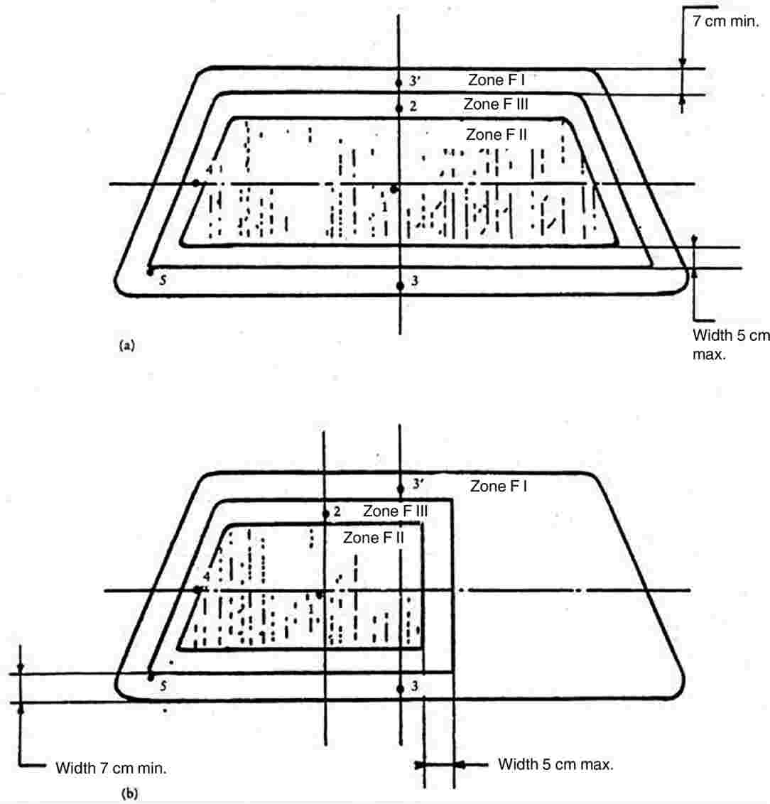

The points ‘2’ shown in Figures 3 (a), 3 (b) and 3 (c) are examples of the sites for point ‘2’ prescribed in point 2.5 of Annex III E.
ANNEX III O
Checks on conformity of production
1. DEFINITIONS
For the purposes of this Annex:
1.1. ‘type of product’ means all glass panes having the same principal characteristics;
1.2. ‘thickness class’ means all glass panes having the thickness of component parts within the permitted tolerances;
1.3. ‘production unit’ means all production facilities of one or several types of glass panes established in the same place; it may include several production lines;
1.4. ‘shift’ means a period of production carried out by the same production line during daily working hours;
1.5. ‘production run’ means a continuous period of production of the same type of product in the same shift;
1.6. ‘Ps’ means the number of glass panes of the same type of product produced by the same shift;
1.7. ‘Pr’ means the number of glass panes of the same type of product produced during a production run.
2. TESTS
The glass panes are subjected to the following tests:
2.1. Toughened-glass windscreens
2.1.1. Fragmentation test in accordance with the requirements of point 2 of Annex III D.
2.1.2. Light transmission measurement in accordance with the requirements of point 9.1 of Annex III C.
2.1.3. Optical distortion test in accordance with the requirements of point 9.2 of Annex III C.
2.1.4. Secondary image separation test in accordance with the requirements of point 9.3 of Annex III C.
2.2. Uniformly toughened glass panes
2.2.1. Fragmentation test in accordance with the requirements of point 2 of Annex III E.
2.2.2. Light transmission measurement in accordance with the requirements of point 9.1 of Annex III C.
In the case of glass panes used as windscreens:
2.2.3.1. Optical distortion test in accordance with the requirements of point 9.2 of Annex III C.
2.2.3.2. Secondary image separation test in accordance with the requirements of point 9.3 of Annex III C.
2.3. Ordinary laminated-glass windscreens and glass-plastic windscreens
2.3.1. Headform test in accordance with the requirements of point 3 of Annex III F.
2.3.2. 2 260-g-ball test in accordance with the requirements of point 4.2 of Annex III F and point 2.2 of Annex III C.
2.3.3. Test of resistance to high temperature in accordance with the requirements of point 5 of Annex III C.
2.3.4. Light transmission measurement in accordance with the requirements of point 9.1 of Annex III C.
2.3.5. Optical distortion test in accordance with the requirements of point 9.2 of Annex III C.
2.3.6. Secondary image separation test in accordance with the requirements of point 9.3 of Annex III C.
In the case of glass-plastic windscreens only:
2.3.7.1. Test of resistance to abrasion in accordance with the requirements of point 2.1 of Annex III I.
2.3.7.2. Resistance-to-humidity test in accordance with the requirements of point 3 of Annex III I.
2.3.7.3. Test of resistance to chemicals in accordance with the requirements of point 11 of Annex III C.
2.4. Ordinary laminated-glass and glass-plastic panes other than windscreens
2.4.1. 227-g-ball impact test in accordance with the requirements of point 4 of Annex III G.
2.4.2. Test of resistance to high temperature in accordance with the requirements of point 5 of Annex III C.
2.4.3. Light transmission measurement in accordance with the requirements of point 9.1 of Annex III C.
In the case of glass-plastic panes only:
2.4.4.1. Test of resistance to abrasion in accordance with the requirements of point 2.1 of Annex III I.
2.4.4.2. Resistance-to-humidity test in accordance with the requirements of point 3 of Annex III I.
2.4.4.3. Test of resistance to chemicals in accordance with the requirements of point 11 of Annex III C.
2.4.5. The above provisions are considered to be met if the corresponding tests have been carried out on a windscreen of the same composition.
2.5. Treated laminated-glass windscreens
2.5.1. In addition to the tests described in point 2.3, a fragmentation test is to be carried out in accordance with the requirements of point 4 of Annex III H.
2.6. Glass panes faced with plastic material
In addition to the tests prescribed in the various points of this Annex, the following tests are to be carried out:
2.6.1. Tests of resistance to abrasion in accordance with the requirements of point 2.1 of Annex III I.
2.6.2. Resistance-to-humidity test in accordance with the requirements of point 3 of Annex III I.
2.6.3. Test of resistance to chemicals in accordance with the requirements of point 11 of Annex III C.
2.7. Double-glazed units
The tests to be performed are those specified in this Annex for each glass pane composing the double-glazed unit, with the same frequency and the same requirements.
3. FREQUENCY OF TESTS AND RESULTS
3.1. Fragmentation
3.1.1. Tests
3.1.1.1. A first series of tests consisting of a break at each impact point specified by this Directive is to be carried out with photographic prints at the beginning of the production of each new type of glass pane to determine the most severe break point.
However, for toughened-glass windscreens, this first series of tests is to be carried out only if the annual production of this type of glass pane exceeds 200 units.
3.1.1.2. During the production run the check test is to be carried out using the break point as determined in point 3.1.1.1.
3.1.1.3. A check is to be carried out at the beginning of each production run or following a change of colour.
3.1.1.4. During the production run the check tests are to be carried out at the following minimum frequency:
|
Toughened-glass windscreens |
Toughened-glass panes other than windscreens |
Treated laminated-glass windscreens |
||
|
Ps ≤ 200: |
one break per production run |
Pr ≤ 500: |
one per shift |
0,1 % per type |
|
Ps > 200: |
one break every four hours of production |
Pr > 500: |
two per shift |
|
3.1.1.5. A check test is to be carried out at the end of the production run on one of the last glass panes manufactured.
3.1.1.6. for Pr < 20, only one fragmentation test per production run need be carried out.
3.1.2. Results
All results must be recorded, including the results without photographic print.
In addition, a photographic contact print must be made once per shift, except for Pr ≤ 500. In this last case only one photographic contact print is made per production run.
3.2. Headform impact test
3.2.1. Tests
The check is to be carried out on samples corresponding to at least 0,5 % of the daily production of laminated-glass windscreens of one production line. A maximum of 15 windscreens per day are tested.
The choice of samples must be representative of the production of the various types of windscreen.
With the agreement of the administrative service, these tests may be replaced by the 2 260-g-ball impact test (see point 3.3. below). Behaviour under head impact must in any event be checked on at least two samples for each thickness class per year.
3.2.2. Results
All results must be recorded.
3.3. 2 260-g-ball impact test
3.3.1. Tests
The minimum frequency for the check is one complete test per month for each thickness class.
3.3.2. Results
All results must be recorded.
3.4. 227-g-ball impact test
3.4.1. Tests
The test pieces are to be cut from samples. However, for practical reasons, the tests may be carried out on finished products, or on parts of them.
The check is to be carried out on a sampling corresponding to at least 0,5 % of the production of one shift with a maximum of 10 samples per day.
3.4.2. Results
All results must be recorded.
3.5. High temperature
3.5.1. Tests
The test pieces are to be cut from samples. However, for practical reasons, the tests may be carried out on finished products or on parts of them. These are selected so that all interlayers are tested proportionately to their use.
The check is to be carried out on at least three samples per colour of interlayer taken from the daily production.
3.5.2. Results
All results must be recorded.
3.6. Light transmission
3.6.1. Tests
Representative samples of tinted finished products are to be submitted to this test.
The check is to be carried out at least at the beginning of every production run if there is any change in the characteristics of the glass pane affecting the results of the test.
Glass panes having a regular light transmission measured during component type-approval of not less than 80 % in the case of windscreens and not less than 75 % in the case of glass panes other than windscreens, and glass panes of category V are exempted from this test.
Alternatively, for toughened-glass panes, a certificate of compliance with the above requirements may be submitted by the glass supplier.
3.6.2. Results
The value of light transmission is to be recorded. In addition, for windscreens with shade bands or obscuration bands, it must be verified, from the drawings referred to in point 3.2.1.2.2.3 of Annex III A, that such bands are outside zone I′.
3.7. Optical distortion and secondary-image separation
3.7.1. Tests
Every windscreen is to be inspected for visual defects. In addition, using the methods specified or any method giving similar results, measurements are to be made in the various areas of vision at the following minimum frequencies:
|
— |
either where Ps ≤ 200, one sample per shift, |
|
— |
or where Ps > 200, two samples per shift, |
|
— |
or 1 % of the whole production, the samples chosen being representative for all production. |
3.7.2. Results
All results must be recorded.
3.8. Resistance to abrasion
3.8.1. Tests
Plastic-faced and glass-plastic panes only are to be subjected to this test. There must be at least one check per month and per type of plastic material facing or interlayer.
3.8.2. Results
The measurement of the light scatter is to be recorded.
3.9. Resistance to humidity
3.9.1. Tests
Plastic-faced and glass-plastic panes only are to be subjected to this test. There must be at least one check per month and per type of plastic material facing or interlayer.
3.9.2. Results
All results must be recorded.
3.10. Resistance to chemicals
3.10.1. Tests
Plastic-faced and glass-plastics panes only are to be subjected to this test. There must be at least one check per month and per type of plastic material facing or interlayer.
3.10.2. Results
All results must be recorded.
ANNEX III P
MODEL
Annex to the EC type-approval certificate for a tractor in respect of the windscreen and other glass panes
(Article 4(2) of Directive 2003/37/EC of the European Parliament and of the Council of 26 May 2003 on type-approval of agricultural or forestry tractors, their trailers and interchangeable towed machinery, together with their systems, components and separate technical units)
EC type-approval No: … Extension No: …
1. Make (name of undertaking) of tractor:
…
2. Type and where appropriate commercial name of tractor:
…
3. Name and address of manufacturer:
…
4. Name and address of manufacturer's authorised representative (if any): …
…
5. Description of type of windscreen and other glass panes (toughened, laminated, plastic, glass-plastic flat, curved, etc.):
…
6. EC component type-approval number of the windscreen and other panes:
…
7. Date on which tractor was submitted for EC type-approval:
…
8. Technical service responsible for type-approval:
…
9. Date of report issued by that service:
…
10. Number of report issued by that service:
…
11. EC component type-approval for the windscreen and other glass panes is granted/refused (1):
12. Place: …
13. Date: …
14. Signature: …
15. The following documents, bearing the EC type-approval number given above, are attached to this document:
… dimensioned drawings;
… sketch or photograph of the windscreen and other glass panes in the tractor cab.
These data must be supplied to the competent authorities of the other Member States at their specific request.
16. Remarks:
…
…
…
…
…
(1) Delete where appropriate.
ANNEX IV
Mechanical couplings between tractor and towed vehicle and vertical load on the coupling point
1. DEFINITIONS
1.1. ‘Mechanical coupling between tractor and towed vehicle’ means the components installed on the tractor and on the towed vehicle in order to provide the mechanical coupling between those vehicles.
Only mechanical coupling components for tractors are covered in this Directive.
Among the various types of mechanical coupling components for tractors a basic distinction is made between:
|
— |
clevis type (see Figures 1 and 2 of Appendix 1), |
|
— |
towing hook (see Figure 1 – ‘Hitch-hook dimensions’ in ISO 6489-1:2001), |
|
— |
tractor drawbar (see Figure 3 of Appendix 1). |
‘Type of mechanical coupling between tractor and towed vehicle’ means parts which do not differ from one another in such essential respects as:
1.2.1. nature of mechanical coupling component,
1.2.2. drawbar rings (40 mm and/or 50 mm diameter),
1.2.3. external shape, dimensions or mode of operation (e.g. automatic or non-automatic),
1.2.4. material,
1.2.5. value of D as defined in Appendix 2 for the test performed using the dynamic method or the trailer mass as defined in Appendix 3 for tests performed using the static method, and also the vertical load on the coupling point S.
1.3. ‘Reference centre of mechanical coupling’ means the point on the pin axis which is equidistant from the wings in the case of a fork and the point resulting from the intersection of the plane of symmetry of the hook with the generatrix of the concave part of the hook at the level of contact with the ring when this is in the traction position.
1.4. ‘Height above ground of mechanical coupling (h)’ means the distance between the horizontal plane through the reference centre of the mechanical coupling and the horizontal plane on which the wheels of the tractor are resting.
1.5. ‘Projection of mechanical coupling (c)’ means the distance between the reference centre of the mechanical coupling component and the vertical plane passing through the axle on which the rear wheels of the tractor are mounted.
1.6. ‘Vertical load on the coupling point (S)’ means the load transmitted, under static conditions on the reference centre of the mechanical coupling.
1.7. ‘Automatic’ means a mechanical coupling component which closes and secures itself when the sliding mechanism for the drawbar rings is actuated, without further action.
1.8. ‘Wheelbase of tractor (l)’ means the distance between the vertical planes perpendicular to the median longitudinal plane of the tractor passing through the axles of the tractor.
1.9. ‘Weight on the front axle of the unladen tractor (ma)’ means that part of the weight of the tractor which, under static conditions, is transmitted on the ground by the front axle of the tractor.
2. GENERAL REQUIREMENTS
2.1. The mechanical coupling components may be designed to function automatically or non-automatically.
2.2. The mechanical coupling components on the tractor must conform to the dimensional and strength requirements in point 3.1 and point 3.2 and the requirements for the vertical load on the coupling point in point 3.3.
2.3. The mechanical coupling components must be so designed and made that in normal use they will continue to function satisfactorily and retain the characteristics prescribed by this Directive.
2.4. All parts of mechanical coupling components must be made of materials of a quality sufficient to withstand the tests referred to in point 3.2. and must have durable strength characteristics.
2.5. All the couplings and their locks must be easy to engage and release and must be so designed that under normal operating conditions no accidental de-coupling is possible.
In automatic coupling components the locked position must be secured in a form-locking manner by two independently functioning safety devices. However, the latter may be released using the same control device.
2.6. The drawbar ring must be capable of tilting horizontally at least 60° on both sides of the longitudinal axis of a non-built-in coupling device. In addition, vertical mobility of 20° upwards and downwards is required at all times. (See also Appendix 1.)
The angles of articulation must not be attained at the same time.
2.7. The jaw must permit the drawbar rings to swivel axially at least 90° to the right or left around the longitudinal axis of the coupling with a fixed braking momentum of between 30 and 150 Nm.
The towing hook must allow the drawbar ring to swivel axially at least 20° to the right or left around the longitudinal axis of the hook.
2.8. Provided at least one mechanical coupling has received EC component type-approval, other types of mechanical link or coupling used in the Member States shall be authorised for a period of 10 years dating from the entry into force of Directive 89/173/EEC without invalidating the EC type-approval of the tractor, on condition that the mounting thereof does not affect the partial approvals.
2.9. In order to prevent unintentional uncoupling from the hitch ring, the distance between the towing hook tip and the keeper (clamping device) shall not exceed 10 mm at the maximum design load.
3. SPECIAL REQUIREMENTS
3.1. Dimensions
The dimensions of the mechanical coupling components on the tractor must comply with Appendix 1, Figures 1, 2 and 3. Any dimensions may be chosen if not shown in these figures.
3.2. Strength
3.2.1. For the purposes of checking their strength the mechanical coupling components must undergo a dynamic test under the conditions set out in Appendix 2 or a static test under the conditions set out in Appendix 3.
3.2.2. The test must not cause any permanent deformation, breaks or tears.
3.3. Vertical load on the coupling point (S)
3.3.1. The maximum static vertical load is laid down by the manufacturer. In no case, however, must it exceed 3 tonnes.
Conditions of acceptance:
3.3.2.1. The permissible static vertical load must not exceed the technically permissible static vertical load recommended by the manufacturer of the tractor nor the static vertical load laid down for the towing device pursuant to EC component type-approval.
3.3.2.2. The requirements of point 2 of Annex I to Directive 2009/63/EC (1) must be complied with, but the maximum load on the rear axle must not be exceeded.
3.4. Height above the ground of the coupling device (h)
(see figure below).
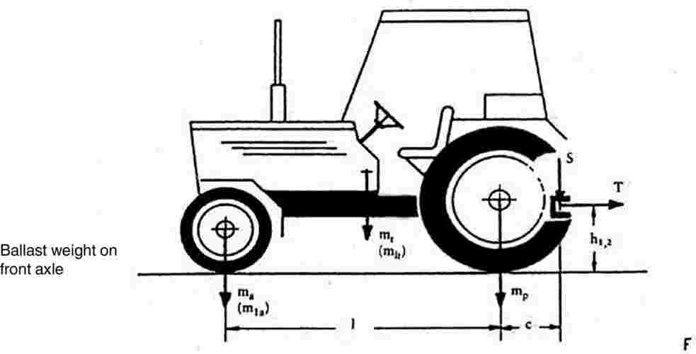
3.4.1. All tractors with a loaded mass exceeding 2,5 tonnes must be fitted with a trailer coupling having a ground clearance satisfying one of the following relations:
![]()
or
![]()
where:
|
mt |
: |
mass of the tractor (see Annex I, point 1.6), |
|
mlt |
: |
mass of the tractor (see Annex I, point 1.6) with ballast weight on the front axle, |
|
ma |
: |
weight on the front axle of the unladen tractor (see Annex IV, point 1.9), |
|
mla |
: |
weight on the front axle of the tractor (see Annex IV, point 1.9) with ballast weight on the front axle, |
|
l |
: |
tractor wheelbase (see Annex IV, point 1.8), |
|
S |
: |
vertical load on the coupling point (see Annex IV, point 1.6), |
|
c |
: |
distance between the reference centre of the mechanical coupling and the vertical plane passing through the axle of the rear wheels of the tractor (see Annex IV, point 1.5). |
4. APPLICATION FOR EC COMPONENT TYPE-APPROVAL
4.1. An application for EC component type-approval for a tractor with respect to the coupling device must be submitted by the manufacturer of the device or by his authorised representative.
4.2. For each type of mechanical coupling component the application must be accompanied by the following documents and particulars:
|
— |
scale drawings of the coupling device (three copies). These drawings must in particular show the required dimensions in detail as well as the measurements for mounting the device, |
|
— |
a short technical description of the coupling device specifying the type of construction and the material used, |
|
— |
a statement of the value of D as referred to in Appendix 2 for the dynamic test or the value of T (traction force) as referred to in Appendix 3 for the static test, and also the vertical load on the coupling point S, |
|
— |
one or more sample devices as required by the technical service. |
5. INSCRIPTIONS
Every mechanical coupling component conforming to the type for which EC component type-approval has been granted must bear the following inscriptions:
5.1.1. trade name or mark;
5.1.2. EC component type-approval mark conforming to the model in Appendix 4;
5.1.3. where the strength is checked in accordance with Appendix 2 (dynamic test):
permissible value of D,
static vertical load value of S;
5.1.4. where the strength is checked in accordance with Appendix 3 (static test):
towable mass and vertical load on the coupling point, S.
5.2. The data must be clearly visible, easily legible and durable.
6. INSTRUCTIONS FOR USE
All mechanical couplings must be accompanied by the manufacturer's instructions for use. These instructions must include the EC component type-approved number and also the values of D or T depending on which test was performed on the coupling.
(1) Directive 2009/63/EC of the European Parliament and of the Council of 13 July 2009 on certain parts and characteristics of wheeled agricultural or forestry tractors (Codified version) (OJ L 214, 19.8.2009, p. 23).
Appendix 1
DRAWINGS OF MECHANICAL COUPLING COMPONENTS
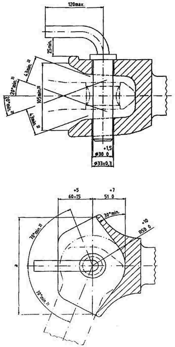
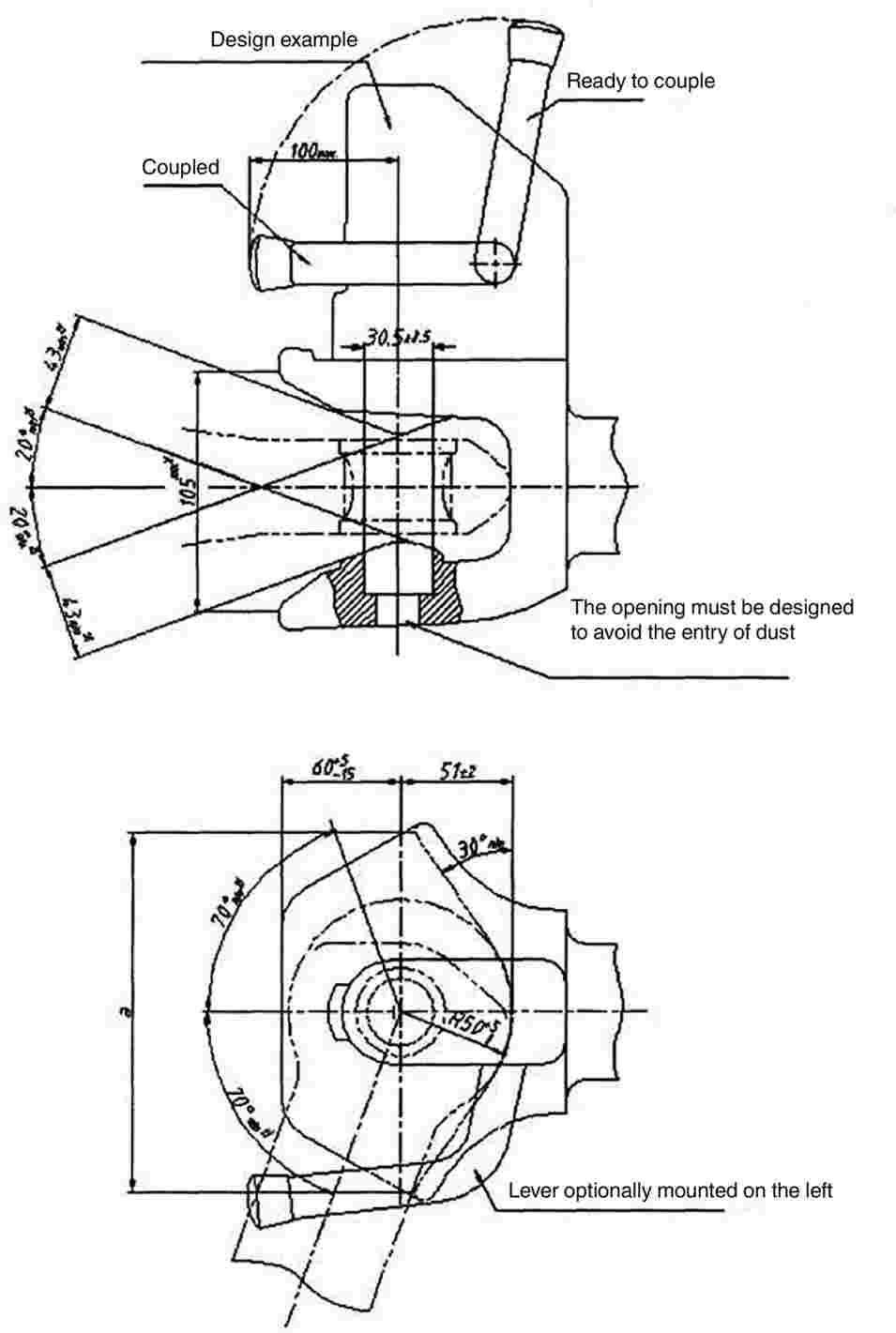


Appendix 2
DYNAMIC TEST METHOD
1. TEST PROCEDURE
The strength of the mechanical coupling is to be established by alternating traction on a test bed.
This method describes the fatigue test to be used on the complete mechanical coupling device, i.e. when fitted with all the parts needed for its installation the mechanical coupling is mounted and tested on a test bed.
The alternating forces are applied as far as possible sinusoidally (alternating and/or rising) with a load cycle depending on the material involved. No tears or breaks may occur during the test.
2. TEST CRITERIA
The horizontal force components in the longitudinal axis of the vehicle together with the vertical force components form the basis of the test loads.
In so far as they are of secondary importance, horizontal force components at right angles to the longitudinal axis of the vehicle and also moments are not to be taken into consideration.
The horizontal force components in the longitudinal axis of the vehicle are represented by a mathematically established representative force, the value D.
The following equation is applied to the mechanical coupling:
D = g · (MT · MR)/(MT + MR)
Where:
|
MT |
= |
the technically permissible total mass of the tractor, |
|
MR |
= |
the technically permissible total mass of the towed vehicles, |
|
g |
= |
9,81 m/s2. |
The vertical force components at right angles to the track are expressed by the static vertical load S.
The technically permissible loads are given by the manufacturer.
3. TEST PROCEDURE
3.1. General requirements
The test force is applied to the mechanical coupling device being tested by means of an appropriate standard drawbar ring beneath an angle formed by the position of the vertical test load Fv vis-à-vis the horizontal test load Fh in the direction of the median longitudinal plane passing from top front to bottom rear.
The test force is applied at the usual point of contact between the mechanical coupling device and the drawbar ring.
The play between the coupling device and the ring must be kept to a minimum.
In principle the test force is applied in an alternating manner around the zero point. With an alternating test force the resulting load is equal to zero.
Should the design of the coupling device (e.g. excessive play, towing hook) make it impossible to carry out the test with an alternating test load, the test load may also be applied on a rising basis in the direction of traction or pressure, whichever is the greater.
Where the test is carried out with a rising force curve, the test load is equal to the upper (highest) load, and the lower (smallest) load should not exceed 5 % of the upper load.
Care should be taken in the alternating force test to ensure that by suitable mounting of the test apparatus and choice of power conduction system no additional moments or forces arising at right angles to the test force are introduced; the angular error for the direction of force in the alternating force test should not exceed ±1,5°; and for the rising force test the angle is set in the upper load position.
The test frequency must not exceed 30 Hz.
For components made of steel or steel casting the load cycle amounts to 2 · 106. The subsequent tear test is carried out using the colour penetration method or similar method.
If springs and/or dampers are incorporated into the coupling parts, they are not to be removed during the test but may be replaced if, during the test, they are subject to strain under conditions which would not obtain during normal operation (e.g. heat action) and become damaged. Their behaviour before, during and after the test must be described in the test report.
3.2. Test forces
The test force consists in geometrical terms of the horizontal and vertical test components as follows:

where:
|
Fh |
= |
±0,6 · D in the case of alternating force, or |
|
Fh |
= |
1,0 · D in the case of rising force (traction or pressure), |
|
Fv |
= |
g · 1,5 · S |
|
S |
= |
static drawbar load (vertical force components on the track). |
Appendix 3
COUPLING DEVICE
STATIC TEST METHOD
1. TEST SPECIFICATIONS
1.1. General
1.1.1. Subject to a check on its construction characteristics, the towing device must undergo static tests in accordance with the requirements of points 1.2, 1.3 and 1.4.
1.2. Test preparation
The tests must be carried out on a special machine, with the towing device and any structure coupling it to the body of the tractor attached to a rigid structure by means of the same components used to mount it on the tractor.
1.3. Test instruments
The instruments used to record loads applied and movements must have the following degree of accuracy:
|
— |
loads applied ±50 daN, |
|
— |
movements ±0,01 mm. |
1.4. Test procedure
The coupling device must first be subjected to a pre-traction load which does not exceed 15 % of the traction test load defined in point 1.4.2.
1.4.1.1. The operation described in point 1.4.1 must be repeated at least twice, starting with a zero load, which is gradually increased until the value prescribed in point 1.4.1 is reached, and then decreased to 500 daN; the settling load must be maintained for at least 60 seconds.
The data recorded for plotting the load/deformation curve under traction, or the graph of that curve provided by the printer linked to the traction machine, must be based on the application of increasing loads only, starting from 500 daN, in relation to the reference centre of the coupling device.
There must be no breaks for values up to and including the traction test load which is established as 1,5 times the technically permissible trailer mass; in addition, the load/deformation curve must show a smooth progression, without irregularities, in the interval between 500 daN and 1/3 of the maximum traction load.
1.4.2.1. Permanent deformation is recorded on the load/deformation curve in relation to the load of 500 daN after the test load has been brought back to that value.
1.4.2.2. The permanent deformation value recorded must not exceed 25 % of the maximum elastic deformation occurring.
1.5. The test referred to in point 1.4.2 must be preceded by a test in which an initial load of three times the maximum permissible vertical load recommended by the manufacturer is applied in a gradually increasing manner, starting from an initial load of 500 daN, to the reference centre of the coupling device.
During the test, deformation of the coupling device must not exceed 10 % of the maximum elastic deformation occurring.
The check is carried out after removing the vertical load and returning to the initial load of 500 daN.
Appendix 4
COMPONENT TYPE-APPROVAL MARK
The EC component type-approval mark consists of:
|
— |
a rectangle surrounding the lower-case letter ‘e’ followed by the distinguishing code (letter(s) or number) of the Member State which has granted the component type-approval: 1 for Germany; 2 for France; 3 for Italy; 4 for the Netherlands; 5 for Sweden; 6 for Belgium; 7 for Hungary; 8 for the Czech Republic; 9 for Spain; 11 for the United Kingdom; 12 for Austria; 13 for Luxembourg; 17 for Finland; 18 for Denmark; 19 for Romania; 20 for Poland; 21 for Portugal; 23 for Greece; 24 for Ireland; 26 for Slovenia; 27 for Slovakia; 29 for Estonia; 32 for Latvia; 34 for Bulgaria; 36 for Lithuania; 49 for Cyprus and 50 for Malta, |
|
— |
an EC component type-approval number, which corresponds to the number of the EC component type-approval certificate issued for the type of coupling device in question as regards its strength and dimensions, placed in any convenient position near the rectangle, |
|
— |
by the capital letter ‘D’ or ‘S’ according to which test was performed on the mechanical coupling (dynamic test = D and static test = S) above the rectangle surrounding the lower-case letter ‘e’. |
Example of an EC component type-approval mark

The coupling bearing the EC component type-approval mark shown above is a device for which EC component type-approval was granted in Germany (e 1) under the number 88-563 and on which a dynamic strength test (D) was performed.
Appendix 5
MODEL EC COMPONENT TYPE-APPROVAL CERTIFICATE
NOTIFICATION CONCERNING THE GRANTING, REFUSAL, WITHDRAWAL OR EXTENSION OF EC COMPONENT TYPE-APPROVAL WITH REGARD TO THE STRENGTH AND DIMENSIONS AND VERTICAL LOAD ON THE COUPLING POINT OF A TYPE OF COUPLING DEVICE (CLEVIS TYPE, TOWING HOOK TRACTOR AND DRAWBAR)
EC component type-approval No:
…
… extension (1)
1. Trade name or mark:
…
…
2. Type of coupling device (clevis type, towing hook, tractor drawbar) (2):
…
3. Name and address of manufacturer of coupling device:
…
…
4. If applicable, name and address of authorised representative of manufacturer of coupling device:
…
The coupling device was subjected to a dynamic/static (2) test and approved for the following values:
5.1. Dynamic test:
value of D:
… (kN)
vertical load on the coupling point:
… (daN)
5.2. Static test:
towable mass:
… (kg)
vertical load on the coupling point:
… (daN)
6. Submitted for EC component type-approval on:
…
7. Technical service responsible for carrying out the tests:
…
8. Date and number of test report:
…
9. EC component type-approval in respect of the mechanical coupling is granted/refused (2):
…
10. Place: …
11. Date: …
12. The following documents, bearing the component type-approval number shown above, are attached to this certificate (e.g. test report, drawings, etc.). This information is to be made available to the competent services of the other Member States only by express request:
…
…
13. Remarks:
…
14. Signature: …
(1) If applicable, state whether this is the first, second, etc., extension of the original EC component type-approval.
(2) Delete where appropriate.
Appendix 6
CONDITIONS FOR GRANTING EC TYPE-APPROVAL
1. The application for EC type-approval of a tractor, with regard to the strength and dimensions of a coupling device, is submitted by the tractor manufacturer or by his authorised representative.
2. A tractor representative of the tractor type to be approved, on which a coupling device, duly approved, is mounted is submitted to the technical services responsible for conducting the type-approval tests.
3. The technical service responsible for conducting the type-approval tests checks whether the approved type of coupling device is suitable for mounting on the type of tractor for which type-approval is requested. In particular, it ascertains that the attachment of the coupling device corresponds to that which was tested when the EC component type-approval was granted.
4. The holder of the EC type-approval may ask for its extension for other types of coupling device.
The competent authorities grant such extension on the following conditions:
5.1. the new type of coupling device has received EC component type-approval;
5.2. it is suitable for mounting on the type of tractor for which the extension of the EC type-approval is requested;
5.3. the attachment of the coupling device on the tractor corresponds to that which was presented when EC component type-approval was granted.
6. A certificate, of which a model is shown in Appendix 5, is annexed to the EC type-approval certificate for each type-approval or type-approval extension which has been granted or refused.
7. If the application for EC type-approval for a type of tractor is made at the same time as the request for EC component type-approval for a type of coupling device on a tractor for which EC type-approval is requested, then points 2 and 3 are unnecessary.
Appendix 7
MODEL
ANNEX TO THE EC TYPE-APPROVAL CERTIFICATE FOR A TRACTOR TYPE WITH REGARD TO THE COUPLING DEVICE AND THE STRENGTH OF ITS ATTACHMENT TO THE TRACTOR
(Article 4(2) of Directive 2003/37/EC of the European Parliament and of the Council of 26 May 2003 on type-approval of agricultural or forestry tractors, their trailers and interchangeable towed machinery, together with their systems, components and separate technical units)
EC type-approval No: …
… extension (1)
1. Trade name or mark of tractor:
…
2. Tractor type and trade name:
…
3. Name and address of tractor manufacturer:
…
…
4. If applicable, name and address of manufacturer's authorised representative:
…
…
5. Trade name or mark of coupling device:
…
…
6. Type(s) of coupling device(s):
…
7. EC mark and EC component type-approval number:
…
8. Extension of EC type-approval to the following type(s) of coupling:
…
…
9. Permissible static vertical load on the coupling point:
… daN
10. Tractor submitted for EC type-approval testing on:
…
11. Technical service responsible for EC type-approval tests:
…
12. Date of test report issued by that technical service:
…
13. Number of test report issued by that service:
…
14. EC type-approval with regard to the coupling device and the strength of its attachment to the tractor has been granted/refused (2).
15. The extension of the EC type-approval with regard to the coupling device and the strength of its attachment to the tractor has been granted/refused (2):
…
16. Place: …
17. Date: …
18. Signature: …
(1) If applicable, state whether this is the first, second, etc., extension of the original EC type-approval.
(2) Delete where appropriate.
ANNEX V
Location and method of affixing statutory plates and inscriptions on the body of the tractor
1. GENERAL
1.1. All agricultural or forestry tractors must be provided with the plate and inscriptions described in the following points. The plate and inscriptions are attached either by the manufacturer or by his authorised representative.
2. MANUFACTURER'S PLATE
A manufacturer's plate, modelled on that shown in the Appendix hereto, must be firmly attached in a conspicuous and readily accessible position on a part normally not subject to replacement in use. It must show clearly and indelibly the following information in the order listed.
2.1.1. Name of manufacturer.
2.1.2. Type of tractor (and version if necessary).
2.1.3. EC type-approval number:
The EC type-approval number consists of the lower-case letter ‘e’ followed by the distinguishing code (letter(s) or number) of the Member State which has granted the EC type-approval:
1 for Germany; 2 for France; 3 for Italy; 4 for the Netherlands; 5 for Sweden; 6 for Belgium; 7 for Hungary; 8 for the Czech Republic; 9 for Spain; 11 for the United Kingdom; 12 for Austria; 13 for Luxembourg; 17 for Finland; 18 for Denmark; 19 for Romania; 20 for Poland; 21 for Portugal; 23 for Greece; 24 for Ireland; 26 for Slovenia; 27 for Slovakia; 29 for Estonia; 32 for Latvia; 34 for Bulgaria; 36 for Lithuania; 49 for Cyprus and 50 for Malta,
and the type-approval number which corresponds to the number of the type-approval certificate issued for the type of vehicle.
An asterisk is placed between the letter ‘e’ followed by the distinguishing code of the country granting EC type-approval and the type-approval number.
2.1.4. Tractor identification number.
2.1.5. Minimum and maximum values for the maximum permitted laden mass of the tractor, depending on the possible types of tyre which may be fitted.
2.1.6. Maximum permitted vehicle mass bearing on each tractor axle, according to the possible types of tyre which may be fitted; this information must be listed in order from front to rear.
2.1.7. Technically permissible towable mass(es): as referred to in point 1.7 of Annex I.
2.1.8. Member States may require, for tractors placed on their markets, that the country of final assembly also be indicated in addition to the name of the manufacturer where the final assembly was carried out elsewhere than in the manufacturer's country, but not in a Member State of the Community.
2.2. The manufacturer may give additional information below or to the side of the prescribed inscriptions, outside a clearly marked rectangle enclosing only the information prescribed in points 2.1.1 to 2.1.7 (see example of manufacturer's plate).
3. TRACTOR IDENTIFICATION NUMBER
The tractor identification number is a fixed combination of characters assigned to each tractor by the manufacturer. Its purpose is to ensure that every tractor, and in particular its type, can be clearly identified over a period of 30 years through the intermediary of the manufacturer, without a need for further reference.
The identification number shall comply with the following requirements:
It must be marked on the manufacturer's plate, and also on the chassis, or other similar structure.
3.1.1. It must wherever possible be entered on a single line.
3.1.2. It must be marked on the chassis or other similar structure, on the front right-hand side of the vehicle.
3.1.3. It must be placed in a clearly visible and accessible position by a method such as hammering or stamping, in such a way that it cannot be obliterated or deteriorate.
4. CHARACTERS
4.1. Roman letters and arabic numerals must be used for all of the markings provided for in points 2 and 3. However, the roman letters used in the markings provided for in points 2.1.1 and 3 must be capital letters.
For the tractor identification number:
4.2.1. use of the letters ‘I’‘O’ and ‘Q’ and dashes, asterisks and other special signs is not permitted;
the minimum height of the letters and figures should be as follows:
4.2.2.1. 7 mm for characters marked directly on the chassis, frame or other similar structure of the tractor,
4 mm for characters marked on the manufacturer's plate.
Example of manufacturer's plate
The following example in no way prejudices the data which may actually be entered on the manufacturer's plate: it is given solely for information purposes.
|
STELLA TRAKTOR WERKE |
||||||||
|
Type: 846 E |
||||||||
|
EC number: e * 1* 1 792 |
||||||||
|
Identification number: GBS18041947 |
||||||||
|
Total permissible mass (1): 4 820 to 6 310 kg Permissible front axle load (1): 2 390 to 3 200 kg Permissible rear axle road (1): 3 130 to 4 260 kg |
||||||||
|
Permissible towable mass:
|
(1) Depending on the tyres
Appendix
MODEL
Annex to the EC type-approval certificate for a tractor type with regard to the position and the method of affixing statutory plates and inscriptions on the body of the tractor
(Article 4(2) of Directive 2003/37/EC of the European Parliament and of the Council of 26 May 2003 on type-approval of agricultural or forestry tractors, their trailers and interchangeable towed machinery, together with their systems, components and separate technical units)
EC type-approval number: …
1. Make of tractor or business name of manufacturer:
…
2. Type and, if appropriate, trade name of tractor:
…
3. Manufacturer's name and address:
…
4. If applicable, name and address of manufacturer's authorised representative:
…
5. Date of submission of tractor for EC type-approval:
…
6. Technical service conducting the type-approval tests:
…
7. Date of report issued by that service:
…
8. Number of report issued by that service:
…
9. EC type-approval for the location and method of affixing statutory plates and inscriptions on the body of the tractor is granted/refused (1).
10. Place: …
11. Date: …
12. Signature: …
13. The following documents bearing the EC type-approval number indicated above are attached to this certificate:
… dimensioned drawings;
… sketch or photograph of the location and method of affixing statutory plates and inscriptions on the body of the tractor.
The data must be supplied to the competent authorities of the other Member States if they so request.
14. Remarks: …
…
…
…
(1) Delete where appropriate.
ANNEX VI
BRAKE CONTROL OF TOWED VEHICLES AND BRAKE COUPLING BETWEEN THE TRACTOR AND TOWED VEHICLES
1. Where a tractor includes a trailer brake control, the control must be either hand- or foot-operated and it must be possible to moderate and operate it from the driver's seat, but it must not be affected by any operation of other controls.
Where the tractor is fitted with a pneumatic or hydraulic coupling system located between the tractor and the towed mass, only one single control should be fitted for the service braking of the vehicle combination.
2. The braking systems used may be systems the characteristics of which are as defined in Annex I to Directive 76/432/EEC relating to the braking devices of wheeled agricultural or forestry tractors.
The fitting must be designed and effected in such a way as to ensure that the operation of the tractor is not adversely affected in the event of the failure or the poor operation of the towed vehicle's breaking device or in the case of a breach in the coupling.
Where the coupling between the tractor and the towed vehicle(s) is hydraulic or pneumatic it must also comply with one or other of the following conditions.
3.1. Hydraulic coupling:
The hydraulic coupling must be of a single conduit type.
It must comply with standard ISO 5676 of 1983, the projecting section being on the tractor.
Operation of the control must permit zero pressure to be delivered to the coupling head in the rest position; the working pressure must be no less than 10 and no more that 15 MPa.
It must not be possible to disconnect the source of power from the engine.
3.2. Pneumatic coupling:
The coupling between the tractor and the towed vehicle(s) of a dual-conduit type: an automatic conduit and a direct braking conduit operates by an increase in pressure.
The coupling head must comply with standard ISO 1728 of 1980.
Operation of the control must permit a working pressure of no less than 0,65 and no more than 0,8 MPa to be delivered to the coupling head.
Appendix
MODEL
ANNEX TO THE EC TYPE-APPROVAL CERTIFICATE FOR A TRACTOR TYPE WITH REGARD TO THE BRAKE CONTROL OF THE TOWED VEHICLE
(Article 4(2) of Directive 2003/37/EC of the European Parliament and of the Council of 26 May 2003 on type-approval of agricultural or forestry tractors, their trailers and interchangeable towed machinery, together with their systems, components and separate technical units)
EC type-approval No: …
1. Make of tractor (or business name of manufacturer):
…
…
2. Type and where appropriate commercial name of tractor:
…
3. Manufacturer's name and address:
…
4. If applicable, name and address of manufacturer's authorised representative:
…
5. Description of component(s) and/or characteristic(s) of the brake control of the towed vehicle:
…
6. Date of submission of tractor for EC type-approval:
…
7. Technical service conducting the type-approval tests:
…
8. Date of report issued by that service:
…
9. Number of report issued by that service:
…
10. EC type-approval for the brake control of the towed vehicle is granted/refused (1):
11. Place: …
12. Date: …
13. Signature: …
14. The following documents bearing the EC type-approval number indicated above are attached to this certificate:
… sketch or photograph of the relevant parts of the tractor.
These data must be supplied to the competent authorities of the other Member States if they so request.
15. Remarks:
…
…
(1) Delete where appropriate.
ANNEX VII
PART A
Repealed Directive with list of its successive amendments
(referred to in Article 10)
|
Council Directive 89/173/EEC |
|
|
1994 Act of Accession, Annex I, Point XI.C.II.7 |
|
|
Directive 97/54/EC of the European Parliament and of the Council |
only as regards the reference to Directive 89/173/EEC in Article 1, first indent |
|
Commission Directive 2000/1/EC |
|
|
2003 Act of Accession, Annex II, Point I.A.33 |
|
|
Commission Directive 2006/26/EC |
only as regards the reference to Directive 89/173/EEC in Article 4 and Annex IV |
|
Council Directive 2006/96/EC |
only as regards the reference to Directive 89/173/EEC in Article 1 and point A.31 of the Annex |
PART B
List of time-limits for transposition into national law and application
(referred to in Article 10)
|
Directive |
Time-limit for transposition |
Date of application |
|
89/173/EEC |
31 December 1989 |
— |
|
97/54/EC |
22 September 1998 |
23 September 1998 |
|
2000/1/EC |
30 June 2000 |
— |
|
2006/26/EC |
31 December 2006 (1) |
— |
|
2006/96/EC |
1 January 2007 |
— |
(1) In compliance with Article 5 of Directive 2006/26/EC:
|
‘1. |
With effect from 1 January 2007, with respect to vehicles which comply with the requirements laid down respectively in Directives 74/151/EEC, 78/933/EEC, 77/311/EEC and 89/173/EEC as amended by this Directive, Member States shall not, on grounds relating to the subject-matter of the Directive concerned:
|
|
2. |
With effect from 1 July 2007, with respect to vehicles which do not comply with the requirements laid down respectively in Directives 74/151/EEC, 78/933/EEC, 77/311/EEC and 89/173/EEC as amended by this Directive, and on grounds relating to the subject-matter of the Directive concerned, Member States:
|
|
3. |
With effect from 1 July 2009, with respect to vehicles which do not comply with the requirements laid down respectively in Directives 74/151/EEC, 78/933/EEC, 77/311/EEC and 89/173/EEC as amended by this Directive, and on grounds relating to the subject-matter of the Directive concerned, Member States:
|
ANNEX VIII
CORRELATION TABLE
|
Directive 89/173/EEC |
Directive 2006/26/EC |
This Directive |
|
Article 1 |
|
Article 1 |
|
Article 2(1), introductory wording |
Article 5(1), introductory wording |
Article 2(1), first subparagraph, introductory wording |
|
Article 2(1), first to sixth indents |
|
— |
|
Article 2(1), final wording |
|
— |
|
|
Article 5(1), points a and b |
Article 2(1), first subparagraph, points a and b |
|
Article 2(2) |
|
Article 2(1), second subparagraph |
|
— |
Article 5(2) |
Article 2(2) |
|
— |
Article 5(3) |
Article 2(3) |
|
Articles 3 and 4 |
|
Articles 3 and 4 |
|
Article 5(1) |
|
Article 5, first paragraph |
|
Article 5(2) |
|
Article 5, second and third paragraphs |
|
Articles 6 to 9 |
|
Articles 6 to 9 |
|
Article 10(1) |
|
— |
|
Article 10(2) |
|
Article 10 |
|
— |
|
Articles 11 and 12 |
|
Article 11 |
|
Article 13 |
|
Annexes I to VI |
|
Annexes I to VI |
|
— |
|
Annex VII |
|
— |
|
Annex VIII |