ISSN 1725-2555
Official Journal
of the European Union
L 70

English edition
Legislation
Volume 50
9 March 2007
|
ISSN 1725-2555 |
||
|
Official Journal of the European Union |
L 70 |
|
|
|
||
|
English edition |
Legislation |
Volume 50 |
|
Contents |
|
page |
|
|
|
* |
|
|
|
Corrigenda |
|
|
|
* |
||
|
|
* |
||
|
|
* |
||
|
|
* |
|
EN |
Acts whose titles are printed in light type are those relating to day-to-day management of agricultural matters, and are generally valid for a limited period. The titles of all other Acts are printed in bold type and preceded by an asterisk. |
|
9.3.2007 |
EN |
Official Journal of the European Union |
L 70/1 |
NOTICE TO READERS
|
BG |
: |
Настоящият брой на Официален вестник е публикуван на испански, чешки, датски, немски, естонски, гръцки, английски, френски, италиански, латвийски, литовски, унгарски, малтийски, нидерландски, полски, португалски, словашки, словенски, фински и шведски език. Поправката, включена в него, се отнася до актове, публикувани преди разширяването на Европейския съюз от 1 януари 2007 г. |
|
ES |
: |
El presente Diario Oficial se publica en español, checo, danés, alemán, estonio, griego, inglés, francés, italiano, letón, lituano, húngaro, maltés, neerlandés, polaco, portugués, eslovaco, esloveno, finés y sueco. Las correcciones de errores que contiene se refieren a los actos publicados con anterioridad a la ampliación de la Unión Europea del 1 de enero de 2007. |
|
CS |
: |
Tento Úřední věstník se vydává ve španělštině, češtině, dánštině, němčině, estonštině, řečtině, angličtině, francouzštině, italštině, lotyštině, litevštině, maďarštině, maltštině, nizozemštině, polštině, portugalštině, slovenštině, slovinštině, finštině a švédštině. Oprava zde uvedená se vztahuje na akty uveřejněné před rozšířením Evropské unie dne 1. ledna 2007. |
|
DA |
: |
Denne EU-Tidende offentliggøres på dansk, engelsk, estisk, finsk, fransk, græsk, italiensk, lettisk, litauisk, maltesisk, nederlandsk, polsk, portugisisk, slovakisk, slovensk, spansk, svensk, tjekkisk, tysk og ungarsk. Berigtigelserne heri henviser til retsakter, som blev offentliggjort før udvidelsen af Den Europæiske Union den 1. januar 2007. |
|
DE |
: |
Dieses Amtsblatt wird in Spanisch, Tschechisch, Dänisch, Deutsch, Estnisch, Griechisch, Englisch, Französisch, Italienisch, Lettisch, Litauisch, Ungarisch, Maltesisch, Niederländisch, Polnisch, Portugiesisch, Slowakisch, Slowenisch, Finnisch und Schwedisch veröffentlicht. Die darin enthaltenen Berichtigungen beziehen sich auf Rechtsakte, die vor der Erweiterung der Europäischen Union am 1. Januar 2007 veröffentlicht wurden. |
|
ET |
: |
Käesolev Euroopa Liidu Teataja ilmub hispaania, tšehhi, taani, saksa, eesti, kreeka, inglise, prantsuse, itaalia, läti, leedu, ungari, malta, hollandi, poola, portugali, slovaki, slovneeni, soome ja rootsi keeles. Selle parandustega viidatakse aktidele, mis on avaldatud enne Euroopa Liidu laienemist 1. jaanuaril 2007. |
|
EL |
: |
Η παρούσα Επίσημη Εφημερίδα δημοσιεύεται στην ισπανική, τσεχική, δανική, γερμανική, εσθονική, ελληνική, αγγλική, γαλλική, ιταλική, λεττονική, λιθουανική, ουγγρική, μαλτέζικη, ολλανδική, πολωνική, πορτογαλική, σλοβακική, σλοβενική, φινλανδική και σουηδική γλώσσα. Τα διορθωτικά που περιλαμβάνει αναφέρονται σε πράξεις που δημοσιεύθηκαν πριν από τη διεύρυνση της Ευρωπαϊκής Ένωσης την 1η Ιανουαρίου 2007. |
|
EN |
: |
This Official Journal is published in Spanish, Czech, Danish, German, Estonian, Greek, English, French, Italian, Latvian, Lithuanian, Hungarian, Maltese, Dutch, Polish, Portuguese, Slovak, Slovenian, Finnish and Swedish. The corrigenda contained herein refer to acts published prior to enlargement of the European Union on 1 January 2007. |
|
FR |
: |
Le présent Journal officiel est publié dans les langues espagnole, tchèque, danoise, allemande, estonienne, grecque, anglaise, française, italienne, lettone, lituanienne, hongroise, maltaise, néerlandaise, polonaise, portugaise, slovaque, slovène, finnoise et suédoise. Les rectificatifs qu'il contient se rapportent à des actes publiés antérieurement à l'élargissement de l'Union européenne du 1er janvier 2007. |
|
IT |
: |
La presente Gazzetta ufficiale è pubblicata nelle lingue spagnola, ceca, danese, tedesca, estone, greca, inglese, francese, italiana, lettone, lituana, ungherese, maltese, olandese, polacca, portoghese, slovacca, slovena, finlandese e svedese. Le rettifiche che essa contiene si riferiscono ad atti pubblicati anteriormente all'allargamento dell'Unione europea del 1o gennaio 2007. |
|
LV |
: |
Šis Oficiālais Vēstnesis publicēts spāņu, čehu, dāņu, vācu, igauņu, grieķu, angļu, franču, itāļu, latviešu, lietuviešu, ungāru, maltiešu, holandiešu, poļu, portugāļu, slovāku, slovēņu, somu un zviedru valodā. Šeit minētie labojumi attiecas uz tiesību aktiem, kas publicēti pirms Eiropas Savienības paplašināšanās 2007. gada 1. janvārī. |
|
LT |
: |
Šis Oficialusis leidinys išleistas ispanų, čekų, danų, vokiečių, estų, graikų, anglų, prancūzų, italų, latvių, lietuvių, vengrų, maltiečių, olandų, lenkų, portugalų, slovakų, slovėnų, suomių ir švedų kalbomis. Čia išspausdintas teisės aktų, paskelbtų iki Europos Sąjungos plėtros 2007 m. sausio 1 d., klaidų ištaisymas. |
|
HU |
: |
Ez a Hivatalos Lap spanyol, cseh, dán, német, észt, görög, angol, francia, olasz, lett, litván, magyar, máltai, holland, lengyel, portugál, szlovák, szlovén, finn és svéd nyelven jelenik meg. Az itt megjelent helyesbítések elsősorban a 2007. január 1-jei európai uniós bővítéssel kapcsolatos jogszabályokra vonatkoznak. |
|
MT |
: |
Dan il-Ġurnal Uffiċjali hu ppubblikat fil-ligwa Spanjola, Ċeka, Daniża, Ġermaniża, Estonjana, Griega, Ingliża, Franċiża, Taljana, Latvjana, Litwana, Ungeriża, Maltija, Olandiża, Pollakka, Portugiża, Slovakka, Slovena, Finlandiża u Żvediża. Il-corrigenda li tinstab hawnhekk tirreferi għal atti ppubblikati qabel it-tkabbir ta' l-Unjoni Ewropea fl-1 ta' Jannar 2007. |
|
NL |
: |
Dit Publicatieblad wordt uitgegeven in de Spaanse, de Tsjechische, de Deense, de Duitse, de Estse, de Griekse, de Engelse, de Franse, de Italiaanse, de Letse, de Litouwse, de Hongaarse, de Maltese, de Nederlandse, de Poolse, de Portugese, de Slowaakse, de Sloveense, de Finse en de Zweedse taal. De rectificaties in dit Publicatieblad hebben betrekking op besluiten die vóór de uitbreiding van de Europese Unie op 1 januari 2007 zijn gepubliceerd. |
|
PL |
: |
Niniejszy Dziennik Urzędowy jest wydawany w językach: hiszpańskim, czeskim, duńskim, niemieckim, estońskim, greckim, angielskim, francuskim, włoskim, łotewskim, litewskim, węgierskim, maltańskim, niderlandzkim, polskim, portugalskim, słowackim, słoweńskim, fińskim i szwedzkim. Sprostowania zawierają odniesienia do aktów opublikowanych przed rozszerzeniem Unii Europejskiej dnia 1 stycznia 2007 r. |
|
PT |
: |
O presente Jornal Oficial é publicado nas línguas espanhola, checa, dinamarquesa, alemã, estónia, grega, inglesa, francesa, italiana, letã, lituana, húngara, maltesa, neerlandesa, polaca, portuguesa, eslovaca, eslovena, finlandesa e sueca. As rectificações publicadas neste Jornal Oficial referem-se a actos publicados antes do alargamento da União Europeia de 1 de Janeiro de 2007. |
|
RO |
: |
Prezentul Jurnal Oficial este publicat în limbile spaniolă, cehă, daneză, germană, estonă, greacă, engleză, franceză, italiană, letonă, lituaniană, maghiară, malteză, olandeză, polonă, portugheză, slovacă, slovenă, finlandeză şi suedeză. Rectificările conţinute în acest Jurnal Oficial se referă la acte publicate anterior extinderii Uniunii Europene din 1 ianuarie 2007. |
|
SK |
: |
Tento úradný vestník vychádza v španielskom, českom, dánskom, nemeckom, estónskom, gréckom, anglickom, francúzskom, talianskom, lotyšskom, litovskom, maďarskom, maltskom, holandskom, poľskom, portugalskom, slovenskom, slovinskom, fínskom a švédskom jazyku. Korigendá, ktoré obsahuje, odkazujú na akty uverejnené pred rozšírením Európskej únie 1. januára 2007. |
|
SL |
: |
Ta Uradni list je objavljen v španskem, češkem, danskem, nemškem, estonskem, grškem, angleškem, francoskem, italijanskem, latvijskem, litovskem, madžarskem, malteškem, nizozemskem, poljskem, portugalskem, slovaškem, slovenskem, finskem in švedskem jeziku. Vsebovani popravki se nanašajo na akte objavljene pred širitvijo Evropske unije 1. januarja 2007. |
|
FI |
: |
Tämä virallinen lehti on julkaistu espanjan, tšekin, tanskan, saksan, viron, kreikan, englannin, ranskan, italian, latvian, liettuan, unkarin, maltan, hollannin, puolan, portugalin, slovakin, sloveenin, suomen ja ruotsin kielellä. Lehden sisältämät oikaisut liittyvät ennen Euroopan unionin laajentumista 1. tammikuuta 2007 julkaistuihin säädöksiin. |
|
SV |
: |
Denna utgåva av Europeiska unionens officiella tidning publiceras på spanska, tjeckiska, danska, tyska, estniska, grekiska, engelska, franska, italienska, lettiska, litauiska, ungerska, maltesiska, nederländska, polska, portugisiska, slovakiska, slovenska, finska och svenska. Rättelserna som den innehåller avser rättsakter som publicerades före utvidgningen av Europeiska unionen den 1 januari 2007. |
Corrigenda
|
9.3.2007 |
EN |
Official Journal of the European Union |
L 70/3 |
Corrigendum to Regulation No 49 of the Economic Commission for Europe of the United Nations (UN/ECE) — Uniform provisions concerning the approval of compression-ignition (C.I.) and natural gas (NG) engines as well as positive-ignition (P.I.) engines fuelled with liquefied petroleum gas (LPG) and vehicles equipped with C.I. and NG engines and P.I. engines fuelled with lpg, with regard to the emissions of pollutants by the engine
( Official Journal of the European Union L 375 of 27 December 2006 )
Regulation No 49 should read as follows:
Regulation No 49 of the Economic Commission for Europe of the United Nations (UN/ECE) — Uniform provisions concerning the approval of compression-ignition (C.I.) and natural gas (NG) engines as well as positive-ignition (P.I.) engines fuelled with liquefied petroleum gas (LPG) and vehicles equipped with c.i. and ng engines and P.I. engines fuelled with lpg, with regard to the emissions of pollutants by the engine
Revision 3
Incorporating:
01 series of amendments — Date of entry into force: 14 May 1990
02 series of amendments — Date of entry into force: 30 December 1992
Corrigendum 1 to the 02 series of amendments subject of depositary notification
C.N.232.1992.TREATIES-32 dated 11 September 1992
Corrigendum 2 to the 02 series of amendments subject of depositary notification
C.N.353.1995.TREATIES-72 dated 13 November 1995
Corrigendum 1 to Revision 2 (Erratum — English only)
Supplement 1 to the 02 series of amendments — Date of entry into force: 18 May 1996
Supplement 2 to the 02 series of amendments — Date of entry into force: 28 August 1996
Corrigendum 1 to Supplement 1 to the 02 series of amendments subject of depositary notification
C.N.426.1997.TREATIES-96 dated 21 November 1997
Corrigendum 2 to Supplement 1 to the 02 series of amendments subject of depositary notification
C.N.272.1999.TREATIES-2 dated 12 April 1999
Corrigendum 1 to Supplement 2 to the 02 series of amendments subject of depositary notification
C.N.271.1999.TREATIES-1 dated 12 April 1999
03 series of amendments — Date of entry into force: 27 December 2001
04 series of amendments — Date of entry into force: 31 January 2003
1. SCOPE
This Regulation applies to the emission of gaseous and particulate pollutants from C.I. and NG engines and P.I. engines fuelled with LPG, used for driving motor vehicles having a design speed exceeding 25 km/h of categories (1) (2) M1 having a total mass exceeding 3,5 tonnes, M2, M3, N1, N2 and N3.
2. DEFINITIONS AND ABBREVIATIONS
For the purposes of this Regulation:
2.1. ‘test cycle’ means a sequence of test points each with a defined speed and torque to be followed by the engine under steady state (ESC test) or transient operating conditions (ETC, ELR test);
2.2. ‘approval of an engine (engine family)’ means the approval of an engine type (engine family) with regard to the level of the emission of gaseous and particulate pollutants;
2.3. ‘diesel engine’ means an engine which works on the compression-ignition principle;
‘gas engine’ means an engine, which is fuelled with natural gas (NG) or liquid petroleum gas (LPG);
2.4. ‘engine type’ means a category of engines which do not differ in such essential respects as engine characteristics as defined in annex 1 to this Regulation;
2.5. ‘engine family’ means a manufacturers grouping of engines which, through their design as defined in annex 1, appendix 2 to this Regulation, have similar exhaust emission characteristics; all members of the family must comply with the applicable emission limit values;
2.6. ‘parent engine’ means an engine selected from an engine family in such a way that its emissions characteristics will be representative for that engine family;
2.7. ‘gaseous pollutants’ means carbon monoxide, hydrocarbons (assuming a ratio of CH1,85 for diesel, CH2,525 for LPG and an assumed molecule CH3O0,5 for ethanol-fuelled diesel engines), non-methane hydrocarbons (assuming a ratio of CH1,85 for diesel fuel, CH2,525 for LPG and CH2,93 for NG), methane (assuming a ratio of CH4 for NG) and oxides of nitrogen, the last-named being expressed in nitrogen dioxide (NO2) equivalent;
‘particulate pollutants’ means any material collected on a specified filter medium after diluting the exhaust with clean filtered air so that the temperature does not exceed 325 K (52 °C);
2.8. ‘smoke’ means particles suspended in the exhaust stream of a diesel engine which absorb, reflect, or refract light;
2.9. ‘net power’ means the power in ECE kW obtained on the test bench at the end of the crankshaft, or its equivalent, measured in accordance with the method of measuring power as set out in Regulation No 24.
2.10. ‘declared maximum power (Pmax)’ means the maximum power in ECE kW (net power) as declared by the manufacturer in his application for approval;
2.11. ‘per cent load’ means the fraction of the maximum available torque at an engine speed;
2.12. ‘ESC test’ means a test cycle consisting of 13 steady state modes to be applied in accordance with paragraph 5.2. of this Regulation;
2.13. ‘ELR test’ means a test cycle consisting of a sequence of load steps at constant engine speeds to be applied in accordance with paragraph 5.2. of this Regulation;
2.14. ‘ETC test’ means a test cycle consisting of 1 800 second-by-second transient modes to be applied in accordance with paragraph 5.2. of this Regulation;
2.15. ‘engine operating speed range’ means the engine speed range, most frequently used during engine field operation, which lies between the low and high speeds, as set out in annex 4 to this Regulation;
2.16. ‘low speed (nlo)’ means the lowest engine speed where 50 per cent of the declared maximum power occurs;
2.17. ‘high speed (nhi)’ means the highest engine speed where 70 per cent of the declared maximum power occurs;
2.18. ‘engine speeds A, B and C’ means the test speeds within the engine operating speed range to be used for the ESC test and the ELR test, as set out in annex 4, appendix 1 to this Regulation;
2.19. ‘control area’ means the area between the engine speeds A and C and between 25 to 100 per cent load;
2.20. ‘reference speed (nref)’ means the 100 per cent speed value to be used for denormalizing the relative speed values of the ETC test, as set out in annex 4, appendix 2 to this Regulation;
2.21. ‘opacimeter’ means an instrument designed to measure the opacity of smoke particles by means of the light extinction principle;
2.22. ‘NG gas range’ means one of the H or L range as defined in European Standard EN 437, dated November 1993;
2.23. ‘self adaptability’ means any engine device allowing the air/fuel ratio to be kept constant;
2.24. ‘recalibration’ means a fine-tuning of a NG engine in order to provide the same performance (power, fuel consumption) in a different range of natural gas;
2.25. ‘Wobbe Index (lower Wl; or upper Wu)’ means the ratio of the corresponding calorific value of a gas per unit volume and the square root of its relative density under the same reference conditions:

2.26. ‘λ-shift factor (Sλ)’ means an expression that describes the required flexibility of the engine management system regarding a change of the excess-air ratio λ if the engine is fuelled with a gas composition different from pure methane (see annex 8 for the calculation of Sλ).
2.27. ‘EEV’ means Enhanced Environmentally Friendly Vehicle which is a type of vehicle propelled by an engine complying with the permissive emission limit values given in row C of the Tables in paragraph 5.2.1. of this Regulation;
2.28. ‘Defeat Device’ means a device which measures, senses or responds to operating variables (e.g. vehicle speed, engine speed, gear used, temperature, intake pressure or any other parameter) for the purpose of activating, modulating, delaying or deactivating the operation of any component or function of the emission control system such that the effectiveness of the emission control system is reduced under conditions encountered during normal vehicle use unless the use of such a device is substantially included in the applied emission certification test procedures.
2.29. ‘Auxiliary control device’ means a system, function or control strategy installed to an engine or on a vehicle, that is used to protect the engine and/or its ancillary equipment against operating conditions that could result in damage or failure, or is used to facilitate engine starting. An auxiliary control device may also be a strategy or measure that has been satisfactorily demonstrated not to be a defeat device.
2.30. ‘Irrational emission control strategy’ means any strategy or measure that, when the vehicle is operated under normal conditions of use, reduces the effectiveness of the emission control system to a level below that expected on the applicable emission test procedures.

2.31. Symbols and Abbreviations
2.31.1. Symbols for Test Parameters
|
Symbol |
Unit |
Term |
|
AP |
m2 |
Cross sectional area of the isokinetic sampling probe |
|
AT |
m2 |
Cross sectional area of the exhaust pipe |
|
CEE |
— |
Ethane efficiency |
|
CEM |
— |
Methane efficiency |
|
C1 |
— |
Carbon 1 equivalent hydrocarbon |
|
conc |
ppm/vol% |
Subscript denoting concentration |
|
D0 |
m3/s |
Intercept of PDP calibration function |
|
DF |
— |
Dilution factor |
|
D |
— |
Bessel function constant |
|
E |
— |
Bessel function constant |
|
EZ |
g/kWh |
Interpolated NOx emission of the control point |
|
fa |
— |
Laboratory atmospheric factor |
|
fc |
s–1 |
Bessel filter cut-off frequency |
|
FFH |
— |
Fuel specific factor for the calculation of wet concentration for dry concentration |
|
FS |
— |
Stoichiometric factor |
|
GAIRW |
kg/h |
Intake air mass flow rate on wet basis |
|
GAIRD |
kg/h |
Intake air mass flow rate on dry basis |
|
GDILW |
kg/h |
Dilution air mass flow rate on wet basis |
|
GEDFW |
kg/h |
Equivalent diluted exhaust gas mass flow rate on wet basis |
|
GEXHW |
kg/h |
Exhaust gas mass flow rate on wet basis |
|
GFUEL |
kg/h |
Fuel mass flow rate |
|
GTOTW |
kg/h |
Diluted exhaust gas mass flow rate on wet basis |
|
H |
MJ/m3 |
Calorific value |
|
HREF |
g/kg |
Reference value of absolute humidity (10,71 g/kg) |
|
Ha |
g/kg |
Absolute humidity of the intake air |
|
Hd |
g/kg |
Absolute humidity of the dilution air |
|
HTCRAT |
mol/mol |
Hydrogen-to-Carbon ratio |
|
I |
— |
Subscript denoting an individual mode |
|
K |
— |
Bessel constant |
|
K |
m–1 |
Light absorption coefficient |
|
KH,D |
— |
Humidity correction factor for NOx for diesel engines |
|
KH,G |
— |
Humidity correction factor for NOx for gas engines |
|
KV |
|
CFV calibration function |
|
KW,a |
— |
Dry to wet correction factor for the intake air |
|
KW,d |
— |
Dry to wet correction factor for the dilution air |
|
KW,e |
— |
Dry to wet correction factor for the diluted exhaust gas |
|
KW,r |
— |
Dry to wet correction factor for the raw exhaust gas |
|
L |
% |
Percent torque related to the maximum torque for the test engine |
|
La |
m |
Effective optical path length |
|
M |
|
Slope of PDP calibration function |
|
Mass |
g/h or g |
Subscript denoting emissions mass flow (rate) |
|
MDIL |
kg |
Mass of the dilution air sample passed through the particulate sampling filters |
|
Md |
mg |
Particulate sample mass of the dilution air collected |
|
Mf |
mg |
Particulate sample mass collected |
|
Mf,p |
mg |
Particulate sample mass collected on primary filter |
|
Mf,b |
mg |
Particulate sample mass collected on back-up filter |
|
MSAM |
kg |
Mass of the diluted exhaust sample passed through the particulate sampling filters |
|
MSEC |
kg |
Mass of secondary dilution air |
|
MTOTW |
kg |
Total CVS mass over the cycle on wet basis |
|
MTOTW,i |
kg |
Instantaneous CVS mass on wet basis |
|
N |
% |
Opacity |
|
NP |
— |
Total revolutions of PDP over the cycle |
|
NP,i |
— |
Revolutions of PDP during a time interval |
|
N |
min–1 |
Engine speed |
|
nP |
s–1 |
PDP speed |
|
nhi |
min–1 |
High engine speed |
|
nlo |
min–1 |
Low engine speed |
|
nref |
min–1 |
Reference engine speed for ETC test |
|
pa |
kPa |
Saturation vapour pressure of the engine intake air |
|
pA |
kPa |
Absolute pressure |
|
pB |
kPa |
Total atmospheric pressure |
|
pd |
kPa |
Saturation vapour pressure of the dilution air |
|
ps |
kPa |
Dry atmospheric pressure |
|
p1 |
kPa |
Pressure depression at pump inlet |
|
P(a) |
kW |
Power absorbed by auxiliaries to be fitted for test |
|
P(b) |
kW |
Power absorbed by auxiliaries to be removed for test |
|
P(n) |
kW |
Net power non-corrected |
|
P(m) |
kW |
Power measured on test bed |
|
Ω |
— |
Bessel constant |
|
Qs |
m3/s |
CVS volume flow rate |
|
q |
— |
Dilution ratio |
|
r |
— |
Ratio of cross sectional areas of isokinetic probe and exhaust pipe |
|
Ra |
% |
Relative humidity of the intake air |
|
Rd |
% |
Relative humidity of the dilution air |
|
Rf |
— |
FID response factor |
|
ρ |
kg/m3 |
Density |
|
S |
kW |
Dynamometer setting |
|
Si |
m–1 |
Instantaneous smoke value |
|
Sλ |
— |
λ-shift factor |
|
T |
K |
Absolute temperature |
|
Ta |
K |
Absolute temperature of the intake air |
|
t |
s |
Measuring time |
|
te |
s |
Electrical response time |
|
tf |
s |
Filter response time for Bessel function |
|
tp |
s |
Physical response time |
|
Δt |
s |
Time interval between successive smoke data (= 1/sampling rate) |
|
Δti |
s |
Time interval for instantaneous CFV flow |
|
τ |
% |
Smoke transmittance |
|
V0 |
m3/rev |
PDP volume flow rate at actual conditions |
|
W |
— |
Wobbe index |
|
Wact |
kWh |
Actual cycle work of ETC |
|
Wref |
kWh |
Reference cycle work of ETC |
|
WF |
— |
Weighting factor |
|
WFE |
— |
Effective weighting factor |
|
X0 |
m3/rev |
Calibration function of PDP volume flow rate |
|
Yi |
m–1 |
1 s Bessel averaged smoke value |
2.31.2. Symbols for the Chemical Components
|
CH4 |
Methane |
|
C2H6 |
Ethane |
|
C2H5OH |
Ethanol |
|
C3H8 |
Propane |
|
CO |
Carbon monoxide |
|
DOP |
Di-octylphtalate |
|
CO2 |
Carbon dioxide |
|
HC |
Hydrocarbons |
|
NMHC |
Non-methane hydrocarbons |
|
NOx |
Oxides of nitrogen |
|
NO |
Nitric oxide |
|
NO2 |
Nitrogen dioxide |
|
PT |
Particulates |
2.31.3. Abbreviations
|
CFV |
Critical flow venturi |
|
CLD |
Chemiluminescent detector |
|
ELR |
European Load Response Test |
|
ESC |
European Steady State Cycle |
|
ETC |
European Transient Cycle |
|
FID |
Flame Ionisation Detector |
|
GC |
Gas Chromatograph |
|
HCLD |
Heated Chemiluminescent Detector |
|
HFID |
Heated Flame Ionisation Detector |
|
LPG |
Liquefied Petroleum Gas |
|
NDIR |
Non-Dispersive Infrared Analyser |
|
NG |
Natural Gas |
|
NMC |
Non-Methane Cutter |
3. APPLICATION FOR APPROVAL
3.1. Application for approval of an engine as a separate technical unit
3.1.1. The application for approval of an engine type with regard to the level of the emission of gaseous and particulate pollutants is submitted by the engine manufacturer or by his duly accredited representative.
3.1.2. It shall be accompanied by the necessary documents in triplicate. It will at least include the essential characteristics of the engine as referred to in annex 1 to this Regulation.
3.1.3. An engine conforming to the ‘engine type’ characteristics described in annex 1 shall be submitted to the technical service responsible for conducting the approval tests defined in paragraph 5.
3.2. Application for approval of a vehicle type in respect of its engine
3.2.1. The application for approval of a vehicle type with regard to emission of gaseous and particulate pollutants by its engine is submitted by the vehicle manufacturer or his duly accredited representative.
It shall be accompanied by the necessary documents in triplicate. It will at least include:
3.2.2.1. The essential characteristics of the engine as referred to in annex 1;
3.2.2.2. A description of the engine related components as referred to in annex 1;
3.2.2.3. A copy of the type approval communication form (annex 2A) for the engine type installed.
3.3. Application for approval for a vehicle type with an approved engine
3.3.1. The application for approval of a vehicle with regard to emission of gaseous and particulate pollutants by its approved diesel engine or engine family and with regard to the level of the emission of gaseous pollutants by its approved gas engine or engine family must be submitted by the vehicle manufacturer or a duly accredited representative.
It must be accompanied by the necessary documents in triplicate and the following particulars:
3.3.2.1. a description of the vehicle type and of engine-related vehicle parts comprising the particulars referred to in annex 1, as applicable, and a copy of the approval communication form (annex 2a) for the engine or engine family, if applicable, as a separate technical unit which is installed in the vehicle type.
4. APPROVAL
4.1. Universal fuel approval
A universal fuel approval is granted subject to the following requirements:
4.1.1. In the case of diesel fuel: if pursuant to paragraphs 3.1., 3.2. or 3.3. of this Regulation, the engine or vehicle meets the requirements of paragraphs 5, 6 and 7 below on the reference fuel specified in annex 5 of this Regulation, approval of that type of engine or vehicle must be granted.
In the case of natural gas the parent engine should demonstrate its capability to adapt to any fuel composition that may occur across the market. In the case of natural gas there are generally two types of fuel, high calorific fuel (H-gas) and low calorific fuel (L-gas), but with a significant spread within both ranges; they differ significantly in their energy content expressed by the Wobbe Index and in their λ-shift factor (Sλ). The formulae for the calculation of the Wobbe index and Sλ are given in paragraphs 2.25. and 2.26. Natural gases with a λ-shift factor between 0,89 and 1,08 (0,89 ≤ Sλ ≤ 1,08) are considered to belong to H-range, while natural gases with a λ-shift factor between 1,08 and 1,19 (1,08 ≤ Sλ ≤ 1,19) are considered to belong to L-range. The composition of the reference fuels reflects the extreme variations of Sλ.
The parent engine must meet the requirements of this Regulation on the reference fuels GR (fuel 1) and G25 (fuel 2), as specified in annex 6, without any readjustment to the fuelling between the two tests. However, one adaptation run over one ETC cycle without measurement is permitted after the change of the fuel. Before testing, the parent engine must be run-in using the procedure given in paragraph 3 of appendix 2 to annex 4.
4.1.2.1. On the manufacturer's request the engine may be tested on a third fuel (fuel 3) if the λ-shift factor (Sλ) lies between 0,89 (i.e. the lower range of GR) and 1,19 (i.e. the upper range of G25), for example when fuel 3 is a market fuel. The results of this test may be used as a basis for the evaluation of the conformity of production.
In the case of an engine fuelled with natural gas which is self-adaptive for the range of H-gases on the one hand and the range of L-gases on the other hand, and which switches between the H-range and the L-range by means of a switch, the parent engine must be tested at each position of the switch on the reference fuel relevant for the respective position as specified in annex 6 for each range. The fuels are GR (fuel 1) and G23 (fuel 3) for the H-range of gases and G25 (fuel 2) and G23 (fuel 3) for the L-range of gases. The parent engine must meet the requirements of this Regulation at both positions of the switch without any readjustment to the fuelling between the two tests at the respective position of the switch. However, one adaptation run over one ETC cycle without measurement is permitted after the change of the fuel. Before testing the parent engine must be run-in using the procedure given in paragraph 3 of appendix 2 to annex 4.
4.1.3.1. On the manufacturer's request the engine may be tested on a third fuel instead of G23 (fuel 3) if the λ-shift factor (Sλ) lies between 0,89 (i.e the lower range of GR) and 1,19 (i.e. the upper range of G25), for example when fuel 3 is a market fuel. The results of this test may be used as a basis for the evaluation of the conformity of the production.
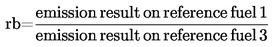
4.1.4. In the case of natural gas engines, the ratio of emission results ‘r’ shall be determined for each pollutant as follows:

or,

and,
In the case of LPG the parent engine should demonstrate its capability to adapt to any fuel composition that may occur across the market. In the case of LPG there are variations in C3/C4 composition. These variations are reflected in the reference fuels. The parent engine should meet the emission requirements on the reference fuels A and B as specified in annex 7 without any readjustment to the fuelling between the two tests. However, one adaptation run over one ETC cycle without measurement is permitted, after the change of the fuel. Before testing the parent engine must be run-in using the procedure defined in paragraph 3 of appendix 2 to annex 4.
4.1.5.1. The ratio of emission results ‘r’ must be determined for each pollutant as follows:

4.2. Granting of a fuel range restricted approval
Fuel range restricted approval is granted subject to the following requirements:
Exhaust emissions approval of an engine running on natural gas and laid out for operation on either the range of H-gases or on the range of L-gases.
The parent engine must be tested on the relevant reference fuel as specified in annex 6 for the relevant range. The fuels are GR (fuel 1) and G23 (fuel 3) for the H-range of gases and G25 (fuel 2) and G23 (fuel 3) for the L-range of gases. The parent engine must meet the requirements of this Regulation without any readjustment to the fuelling between the two tests. However, one adaptation run over one ETC cycle without measurement is permitted after the change of the fuel. Before testing the parent engine must be run-in using the procedure defined in paragraph 3 of appendix 2 to annex 4.
4.2.1.1. On the manufacturer's request the engine may be tested on a third fuel instead of G23 (fuel 3) if the λ-shift factor (Sλ) lies between 0,89 (i.e. the lower range of GR) and 1,19 (i.e. the upper range of G25), for example when fuel 3 is a market fuel. The results of this test may be used as a basis for the evaluation of the conformity of the production.
4.2.1.2. The ratio of emission results ‘r’ must be determined for each pollutant as follows:

or,

and,

4.2.1.3. Upon delivery to the customer the engine must bear a label (see paragraph 4.11.) stating for which range of gases the engine is approved.
Exhaust emissions approval of an engine running on natural gas or LPG and laid out for operation on one specific fuel composition.
4.2.2.1. The parent engine must meet the emission requirements on the reference fuels GR and G25 in the case of natural gas, or the reference fuels A and B in the case of LPG, as specified in annex 7.
Between the tests fine-tuning of the fuelling system is allowed. This fine-tuning will consist of a recalibration of the fuelling database, without any alteration to either the basic control strategy or the basic structure of the database. If necessary the exchange of parts that are directly related to the amount of fuel flow (such as injector nozzles) is allowed.
4.2.2.2. On the manufacturer's request the engine may be tested on the reference fuels GR and G23, or on the reference fuels G25 and G23, in which case the approval is only valid for the H-range or the L-range of gases respectively.
4.2.2.3. Upon delivery to the customer the engine must bear a label (see paragraph 4.11.) stating for which fuel composition the engine has been calibrated.
APPROVAL OF NG-FUELLED ENGINES
|
|
Para. 4.1. Granting of a universal fuel approval |
Number of test runs |
Calculation of ‘r’ |
Para. 4.2. Granting of a fuel restricted approval |
Number of test runs |
Calculation of ‘r’ |
|
Refer to para. 4.1.2. NG-engine adaptable to any fuel composition |
GR (1) and G25 (2) at manufacturer's request engine may be tested on an additional market fuel (3), if Sλ = 0,89 – 1,19 |
2 (max. 3) |
and, if tested with an additional fuel
and
|
|
|
|
|
Refer to para. 4.1.3. NG-engine which is self adaptive by a switch |
GR (1) and G23 (3) for H and G25 (2) and G23 (3) for L at manufacturer's request engine may be tested on a market fuel (3) instead of G23, if Sλ = 0,89 – 1,19 |
2 for the H-range, and 2 for the L-range at respective position of switch 4 |
and
|
|
|
|
|
Refer to para. 4.2.1. NG-engine laid out for operation on either H-range gas or L-range gas |
|
|
|
GR (1) and G23 (3) for H or G25 (2) and G23 (3) for L at manufacturer's request engine may be tested on a market fuel (3) instead of G23, if Sλ = 0,89 – 1,19 |
2 for the H-range or 2 for the L-range 2 |
for the H-range or
for the L-range |
|
Refer to para. 4.2.2. NG-engine laid out for operation on one specific fuel composition |
|
|
|
GR (1) and G25 (2), fine-tuning between the tests allowed at manufacturer's request engine may be tested on GR (1) and G23 (3) for H or G25 (2) and G23 (3) for L |
2 or 2 for the H-range or 2 for the L-range 2 |
|
APPROVAL OF LPG-FUELLED ENGINES
|
|
Para. 4.1. Granting of a universal fuel approval |
Number of test runs |
Calculation of ‘r’ |
Para. 4.2. Granting of a fuel restricted approval |
Number of test runs |
Calculation of ‘r’ |
|
refer to para. 4.1.5 LPG-engine adaptable to any fuel composition |
fuel A and fuel B |
2 |
|
|
|
|
|
refer to para. 4.2.2 LPG-engine laid out for operation on one specific fuel composition |
|
|
|
fuel A and fuel B, fine-tuning between the tests allowed |
2 |
|
4.3. Exhaust emissions approval of a member of a family
4.3.1. With the exception of the case mentioned in paragraph 4.3.2., the approval of a parent engine must be extended to all family members without further testing, for any fuel composition within the range for which the parent engine has been approved (in the case of engines described in paragraph 4.2.2) or the same range of fuels (in the case of engines described in either paragraphs 4.1. or 4.2) for which the parent engine has been approved.
4.3.2. Secondary test engine
In case of an application for approval of an engine, or a vehicle in respect of its engine, that engine belonging to an engine family, if the approval authority determines that, with regard to the selected parent engine the submitted application does not fully represent the engine family defined in the Regulation, appendix 1, an alternative and, if necessary, an additional reference test engine may be selected by the approval authority and tested.
4.4. An approval number shall be assigned to each type approved. Its first two digits (at present 04, corresponding to 04 series of amendments) shall indicate the series of amendments incorporating the most recent major technical amendments made to the Regulation at the time of issue of the approval. The same Contracting Party shall not assign the same number to another engine type or vehicle type.
4.5. Notice of approval or of extension or of refusal of approval or production definitely discontinued of an engine type or vehicle type pursuant to this Regulation shall be communicated to the Parties to the 1958 Agreement which apply this Regulation, by means of a form conforming to the model in annexes 2A or 2B, as applicable, to this Regulation. Values measured during the type test shall also be shown.
There shall be affixed, conspicuously and in a readily accessible place to every engine conforming to an engine type approved under this Regulation, or to every vehicle conforming to a vehicle type approved under this Regulation, an international approval mark consisting of:
4.6.1. a circle surrounding the letter ‘E’ followed by the distinguishing number of the country which has granted approval (3);
4.6.2. the number of this Regulation, followed by the letter ‘R’, a dash and the approval number to the right of the circle prescribed in paragraph 4.4.1.
However, the approval mark must contain an additional character after the letter ‘R’, the purpose of which is to distinguish the emission limit values for which the approval has been granted. For those approvals issued to indicate compliance with the limits contained in Row A of the relevant table(s) in paragraph 5.2.1., the letter ‘R’ will be followed by the Roman number ‘I’. For those approvals issued to indicate compliance with the limits contained in Row B1 of the relevant table(s) in paragraph 5.2.1., the letter ‘R’ will be followed by the Roman number ‘II’. For those approvals issued to indicate compliance with the limits contained in Row B2 of the relevant table(s) in paragraph 5.2.1., the letter ‘R’ will be followed by the Roman number ‘III’. For those approvals issued to indicate compliance with the limits contained in Row C of the relevant table(s) in paragraph 5.2.1., the letter ‘R’ will be followed by the Roman number ‘IV’.
For NG fuelled engines the approval mark must contain a suffix after the national symbol, the purpose of which is to distinguish which range of gases the approval has been granted. This mark will be as follows;
4.6.3.1.1. H in case of the engine being approved and calibrated for the H-range of gases;
4.6.3.1.2. L in case of the engine being approved and calibrated for the L-range of gases;
4.6.3.1.3. HL in case of the engine being approved and calibrated for both the H-range and L-range of gases;
4.6.3.1.4. Ht in case of the engine being approved and calibrated for a specific gas composition in the H-range of gases and transformable to another specific gas in the H-range of gases by fine tuning of the engine fuelling;
4.6.3.1.5. Lt in case of the engine being approved and calibrated for a specific gas composition in the L-range of gases and transformable to another specific gas in the L-range of gases after fine tuning of the engine fuelling;
4.6.3.1.6. HLt in the case of the engine being approved and calibrated for a specific gas composition in either the H-range or the L-range of gases and transformable to another specific gas in either the H-range or the L-range of gases by fine tuning of the engine fuelling.
4.7. If the vehicle or engine conforms to an approved type under one or more other Regulations annexed to the Agreement, in the country which has granted approval under this Regulation, the symbol prescribed in paragraph 4.6.1. need not be repeated. In such a case, the Regulation and approval numbers and the additional symbols of all the Regulations under which approval has been granted under this Regulation shall be placed in vertical columns to the right of the symbol prescribed in paragraph 4.6.1.
4.8. The approval mark shall be placed close to or on the data plate affixed by the manufacturer to the approved type.
4.9. Annex 3 to this Regulation gives examples of arrangements of approval marks.
The engine approved as a technical unit must bear, in addition to the approved mark:
4.10.1. the trademark or trade name of the manufacturer of the engine;
4.10.2. the manufacturer's commercial description.
4.11. Labels
In the case of NG and LPG fuelled engines with a fuel range restricted type approval, the following labels are applicable:
4.11.1. Content
The following information must be given:
In the case of paragraph 4.2.1.3, the label shall state ‘ONLY FOR USE WITH NATURAL GAS RANGE H’. If applicable, ‘H’ is replaced by ‘L’.
In the case of paragraph 4.2.2.3, the label shall state ‘ONLY FOR USE WITH NATURAL GAS SPECIFICATION …’ or ‘ONLY FOR USE WITH LIQUEFIED PETROLEUM GAS SPECIFICATION …’, as applicable. All the information in the relevant table(s) in Annex 6 or 7 shall be given with the individual constituents and limits specified by the engine manufacturer.
The letters and figures must be at least 4 mm in height.
Note: If lack of space prevents such labelling, a simplified code may be used. In this event, explanatory notes containing all the above information must be easily accessible to any person filling the fuel tank or performing maintenance or repair on the engine and its accessories, as well as to the authorities concerned. The site and content of these explanatory notes will be determined by agreement between the manufacturer and the approval authority.
4.11.2. Properties
Labels must be durable for the useful life of the engine. Labels must be clearly legible and their letters and figures must be indelible. Additionally, labels must be attached in such a manner that their fixing is durable for the useful life of the engine, and the labels cannot be removed without destroying or defacing them.
4.11.3. Placing
Labels must be secured to an engine part necessary for normal engine operation and not normally requiring replacement during engine life. Additionally, these labels must be located so as to be readily visible to the average person after the engine has been completed with all the auxiliaries necessary for engine operation.
4.12. In case of an application for type-approval for a vehicle type in respect of its engine, the marking specified in paragraph 4.11. must also be placed close to fuel filling aperture.
4.13. In case of an application for type-approval for a vehicle type with an approved engine, the marking specified in paragraph 4.11. must also be placed close to the fuel filling aperture.
5. SPECIFICATIONS AND TESTS
5.1. General
5.1.1. Emission control equipment
5.1.1.1. The components liable to affect the emission of gaseous and particulate pollutants from diesel engines and the emission of gaseous pollutants from gas engines shall be so designed, constructed, assembled and installed as to enable the engine, in normal use, to comply with the provisions of this Regulation.
5.1.2. Functions of emission control equipment
5.1.2.1. The use of a defeat device and/or an irrational emission control strategy is forbidden.
An auxiliary control device may be installed to an engine, or on a vehicle, provided that the device:
5.1.2.2.1. operates only outside the conditions specified in paragraph 5.1.2.4., or
5.1.2.2.2. is activated only temporarily under the conditions specified in paragraph 5.1.2.4. for such purposes as engine damage protection, air-handling device protection, smoke management, cold start or warming-up, or
5.1.2.2.3. is activated only by on-board signals for purposes such as operational safety and limp-home strategies;
5.1.2.3. An engine control device, function, system or measure that operates during the conditions specified in paragraph 5.1.2.4. and which results in the use of a different or modified engine control strategy to that normally employed during the applicable emission test cycles will be permitted if, in complying with the requirements of paragraphs 5.1.3. and/or 5.1.4., it is fully demonstrated that the measure does not reduce the effectiveness of the emission control system. In all other cases, such devices shall be considered to be a defeat device.
5.1.2.4. For the purposes of paragraph 5.1.2.2., the defined conditions of use under steady state and transient conditions are:
|
(i) |
an altitude not exceeding 1 000 metres (or equivalent atmospheric pressure of 90 kPa), |
|
(ii) |
an ambient temperature within the range 283 to 303 K (10 to 30 °C), |
|
(iii) |
engine coolant temperature within the range 343 to 368 K (70 to 95 °C). |
5.1.3. Special requirements for electronic emission control systems
5.1.3.1. Documentation requirements
The manufacturer shall provide a documentation package that gives access to the basic design of the system and the means by which it controls its output variables, whether that control is direct or indirect.
The documentation shall be made available in two parts:
|
(a) |
The formal documentation package, which shall be supplied to the technical service at the time of submission of the type-approval application, shall include a full description of the system. This documentation may be brief, provided that it exhibits evidence that all outputs permitted by a matrix obtained from the range of control of the individual unit inputs have been identified. This information shall be attached to the documentation required in paragraph 3 of this Regulation. |
|
(b) |
Additional material that shows the parameters that are modified by any auxiliary control device and the boundary conditions under which the device operates. The additional material shall include a description of the fuel system control logic, timing strategies and switch points during all modes of operation. The additional material shall also contain a justification for the use of any auxiliary control device and include additional material and test data to demonstrate the effect on exhaust emissions of any auxiliary control device installed to the engine or on the vehicle. This additional material shall remain strictly confidential and be retained by the manufacturer, but be made open for inspection at the time of type-approval or at any time during the validity of the type-approval. |
To verify whether any strategy or measure should be considered a defeat device or an irrational emission control strategy according to the definitions given in paragraphs 2.28. and 2.30., the type-approval authority and/or the technical service may additionally request a NOx screening test using the ETC which may be carried out in combination with either the type-approval test or the procedures for checking the conformity of production.
5.1.4.1. As an alternative to the requirements of appendix 4 to annex 4 to this Regulation, the emissions of NOx during the ETC screening test may be sampled using the raw exhaust gas and the technical prescriptions of ISO FDIS 16 183, dated 15 September 2001, shall be followed.
5.1.4.2. In verifying whether any strategy or measure should be considered a defeat device or an irrational emission control strategy according to the definitions given in paragraphs 2.28. and 2.30., an additional margin of 10 per cent, related to the appropriate NOx limit value, shall be accepted.
For approval to row A of the tables in paragraph 5.2.1., the emissions must be determined on the ESC and ELR tests with conventional diesel engines including those fitted with electronic fuel injection equipment, exhaust gas recirculation (EGR), and/or oxidation catalysts. Diesel engines fitted with advanced exhaust after-treatment systems including deNOx catalysts and/or particulate traps, must additionally be tested on the ETC test.
For approval testing to either row B1 or B2 or row C of the tables in paragraph 5.2.1. the emissions must be determined on the ESC, ELR and ETC tests.
For gas engines, the gaseous emissions must be determined on the ETC test.
The ESC and ELR test procedures are described in annex 4, appendix 1, the ETC test procedure in annex 4, Appendices 2 and 3.
The emissions of gaseous pollutants and particulate pollutants, by the engine submitted for testing, if applicable, must be measured by the method described in annex 4. Annex 4, appendix 4 describes the recommended analytical systems for the gaseous and particulate pollutants and the recommended particulate sampling systems. Other systems or analysers may be approved by the technical service if it is found that they yield equivalent results. For a single laboratory, equivalency is defined as the test results to fall within ± 5 per cent of the test results of one of the reference systems described herein. For particulate emissions only the full-flow dilution system is recognized as the reference system. For introduction of a new system into the Regulation, the determination of equivalency must be based upon the calculation of repeatability and reproducibility by an inter-laboratory test, as described in ISO 5725.
5.2.1. Limit Values
The specific mass of the carbon monoxide, of the total hydrocarbons, of the oxides of nitrogen and of the particulates, as determined on the ESC test, and of the smoke opacity, as determined on the ELR test, must not exceed the amounts shown in Table 1.
For diesel engines that are additionally tested on the ETC test, and specifically for gas engines, the specific masses of the carbon monoxide, of the non-methane hydrocarbons, of the methane (where applicable), of the oxides of nitrogen and of the particulates (where applicable) must not exceed the amounts shown in Table 2.
Table 1
Limit values — ESC and ELR tests
|
Row |
Mass of carbon monoxide (CO) g/kWh |
Mass of hydrocarbons (HC) g/kWh |
Mass of nitrogen oxides (NOx) g/kWh |
Mass of particulates (PT) g/kWh |
Smoke m–1 |
|
A (2000) |
2,1 |
0,66 |
5,0 |
0,10 0,13 (4) |
0,8 |
|
B1 (2005) |
1,5 |
0,46 |
3,5 |
0,02 |
0,5 |
|
B2 (2008) |
1,5 |
0,46 |
2,0 |
0,02 |
0,5 |
|
C (EEV) |
1,5 |
0,25 |
2,0 |
0,02 |
0,15 |
Table 2
Limit values — ETC tests (6)
|
Row |
Mass of carbon monoxide (CO) g/kWh |
Mass of non-methane hydrocarbons (NMHC) g/kWh |
Mass of methane (CH4) (7) g/kWh |
Mass of nitrogen oxides (NOx) g/kWh |
Mass of particulates (PT) (8) g/kWh |
|
A (2000) |
5,45 |
0,78 |
1,6 |
5,0 |
0,16 0,21 (5) |
|
B1 (2005) |
4,0 |
0,55 |
1,1 |
3,5 |
0,03 |
|
B2 (2008) |
4,0 |
0,55 |
1,1 |
2,0 |
0,03 |
|
C (EEV) |
3,0 |
0,40 |
0,65 |
2,0 |
0,02 |
5.2.2. Hydrocarbon measurement for diesel and gas fuelled engines
5.2.2.1. A manufacturer may choose to measure the mass of total hydrocarbons (THC) on the ETC test instead of measuring the mass of non-methane hydrocarbons. In this case, the limit for the mass of total hydrocarbons is the same as shown in table 2 for the mass of non-methane hydrocarbons.
5.2.3. Specific requirements for diesel engines
5.2.3.1. The specific mass of the oxides of nitrogen measured at the random check points within the control area of the ESC test must not exceed by more than 10 per cent the values interpolated from the adjacent test modes (reference annex 4, appendix 1 paragraphs 4.6.2. and 4.6.3.).
5.2.3.2. The smoke value on the random test speed of the ELR must not exceed the highest smoke value of the two adjacent test speeds by more than 20 per cent, or by more than 5 per cent of the limit value, whichever is greater.
6. INSTALLATION ON THE VEHICLE
The engine installation on the vehicle shall comply with the following characteristics in respect to the type approval of the engine:
6.1.1. Intake depression shall not exceed that specified for the type approved engine in annex 2A.
6.1.2. Exhaust back-pressure shall not exceed that specified for the type approved engine in annex 2A.
6.1.3. Power absorbed by the auxiliaries needed for operating the engine must not exceed that specified for the type-approved engine in annex 2A.
7. ENGINE FAMILY
7.1. Parameters defining the engine family
The engine family, as determined by the engine manufacturer, may be defined by basic characteristics, which must be common to engines within the family. In some cases there may be interaction of parameters. These effects must also be taken into consideration to ensure that only engines with similar exhaust emission characteristics are included within an engine family.
In order that engines may be considered to belong to the same engine family, the following list of basic parameters must be common:
7.1.1. Combustion cycle:
|
— |
2 cycle |
|
— |
4 cycle |
7.1.2. Cooling medium:
|
— |
air |
|
— |
water |
|
— |
oil |
7.1.3. For gas engines and engines with after-treatment
|
— |
Number of cylinders |
(other diesel engines with fewer cylinders than the parent engine may be considered to belong to the same engine family provided the fuelling system meters fuel for each individual cylinder).
7.1.4. Individual cylinder displacement:
|
— |
engines to be within a total spread of 15 per cent |
7.1.5. Method of air aspiration:
|
— |
naturally aspirated |
|
— |
pressure charged |
|
— |
pressure charged with charge air cooler |
7.1.6. Combustion chamber type/design:
|
— |
pre-chamber |
|
— |
swirl chamber |
|
— |
open chamber |
7.1.7. Valve and porting — configuration, size and number:
|
— |
cylinder head |
|
— |
cylinder wall |
|
— |
crankcase |
7.1.8. Fuel injection system (diesel engines):
|
— |
pump-line-injector |
|
— |
in-line pump |
|
— |
distributor pump |
|
— |
single element |
|
— |
unit injector |
7.1.9. Fuelling system (gas engines):
|
— |
mixing unit |
|
— |
gas induction/injection (single point, multi-point) |
|
— |
liquid injection (single point, multi-point) |
7.1.10. Ignition system (gas engines)
7.1.11. Miscellaneous features:
|
— |
exhaust gas recirculation |
|
— |
water injection/emulsion |
|
— |
secondary air injection |
|
— |
charge cooling system |
7.1.12. Exhaust after treatment:
|
— |
3-way-catalyst |
|
— |
oxidation catalyst |
|
— |
reduction catalyst |
|
— |
thermal reactor |
|
— |
particulate trap |
7.2. Choice of the parent engine
7.2.1. Diesel engines
The parent engine of the family must be selected using the primary criteria of the highest fuel delivery per stroke at the declared maximum torque speed. In the event that two or more engines share this primary criteria, the parent engine must be selected using the secondary criteria of highest fuel delivery per stroke at rated speed. Under certain circumstances, the approval authority may conclude that the worst case emission rate of the family can best be characterised by testing a second engine. Thus, the approval authority may select an additional engine for test based upon features, which indicate that it may have the highest emission level of the engines within that family.
If engines within the family incorporate other variable features, which could be considered to affect exhaust emissions, these features must also be identified and taken into account in the selection of the parent engine.
7.2.2. Gas engines
The parent engine of the family must be selected using the primary criteria of the largest displacement. In the event that two or more engines share this primary criteria, the parent engine must be selected using the secondary criteria in the following order:
|
— |
the highest fuel delivery per stroke at the speed of declared rated power; |
|
— |
the most advanced spark timing; |
|
— |
the lowest EGR rate; |
|
— |
no air pump or lowest actual air flow pump. |
Under certain circumstances, the approval authority may conclude that the worst case emission rate of the family can best be characterised by testing a second engine. Thus, the approval authority may select an additional engine for test based upon features, which indicate that it may have the highest emission level of the engines within that family.
8. CONFORMITY OF PRODUCTION
The conformity of production procedures shall comply with those set out in the Agreement, appendix 2 (E/ECE/324-E/ECE/TRANS/505/Rev.2), with the following requirements:
8.1. Every engine or vehicle bearing an approval mark as prescribed under this Regulation shall be so manufactured as to conform, with regard to the description as given in the approval form and its annexes, to the approved type.
8.2. As a general rule, conformity of production with regard to limitation of emissions is checked based on the description given in the communication form and its annexes.
If emissions of pollutants are to be measured and an engine approval has had one or several extensions, the tests will be carried out on the engine(s) described in the information package relating to the relevant extension.
Conformity of the engine subjected to a pollutant test:
After submission of the engine to the authorities, the manufacturer must not carry out any adjustment to the engines selected.
8.3.1.1. Three engines are randomly taken in the series. Engines that are subject to testing only on the ESC and ELR tests or only on the ETC test for approval to row A of the tables in paragraph 5.2.1. are subject to those applicable tests for the checking of production conformity. With the agreement of the authority, all other engines approved to row A, B1 or B2, or C of the tables in paragraph 5.2.1. are subjected to testing either on the ESC and ELR cycles or on the ETC cycle for the checking of the production conformity. The limit values are given in paragraph 5.2.1. of the Regulation.
8.3.1.2. The tests are carried out according to appendix 1 to this Regulation, where the competent authority is satisfied with the production standard deviation given by the manufacturer.
The tests are carried out according to appendix 2 to this Regulation, where the competent authority is not satisfied with the production standard deviation given by the manufacturer.
At the manufacturer's request, the tests may be carried out in accordance with appendix 3 to this Regulation.
8.3.1.3. On the basis of a test of the engine by sampling, the production of a series is regarded as conforming where a pass decision is reached for all the pollutants and non conforming where a fail decision is reached for one pollutant, in accordance with the test criteria applied in the appropriate appendix.
When a pass decision has been reached for one pollutant, this decision may not be changed by any additional tests made in order to reach a decision for the other pollutants.
If no pass decision is reached for all the pollutants and if no fail decision is reached for one pollutant, a test is carried out on another engine (see figure 2).
If no decision is reached, the manufacturer may at any time decide to stop testing. In that case a fail decision is recorded.
The tests will be carried out on newly manufactured engines. Gas fuelled engines must be run-in using the procedure defined in paragraph 3 of appendix 2 to annex 4.
8.3.2.1. However, at the request of the manufacturer, the tests may be carried out on diesel or gas engines which have been run-in more than the period referred to in paragraph 8.4.2.2., up to a maximum of 100 hours. In this case, the running-in procedure will be conducted by the manufacturer who must undertake not to make any adjustments to those engines.
8.3.2.2. When the manufacturer asks to conduct a running-in procedure in accordance with paragraph 8.4.2.2.1., it may be carried out on:
|
— |
all the engines that are tested, |
or,
|
— |
the first engine tested, with the determination of an evolution coefficient as follows:
|
It may be less than one.
The subsequent test engines will not be subjected to the running-in procedure, but their zero hour emissions will be modified by the evolution coefficient.
In this case, the values to be taken will be:
|
— |
the values at ‘x’ hours for the first engine, |
|
— |
the values at zero hour multiplied by the evolution coefficient for the other engines. |
8.3.2.3. For diesel and LPG fuelled engines, all these tests may be conducted with commercial fuel. However, at the manufacturer's request, the reference fuels described in annexes 5 or 7 may be used. This implies tests, as described in paragraph 4. of this Regulation, with at least two of the reference fuels for each gas engine.
8.3.2.4. For NG fuelled engines, all these tests may be conducted with commercial fuel in the following way:
|
(i) |
for H marked engines with a commercial fuel within the H range (0,89 ≤ Sλ ≤ 1,00); |
|
(ii) |
for L marked engines with a commercial fuel within the L range (1,00 ≤ Sλ ≤ 1,19); |
|
(iii) |
for HL marked engines with a commercial fuel within the extreme range of the λ-shift factor (0,89 ≤ Sλ ≤ 1,19). |
However, at the manufacturer's request, the reference fuels described in annex 6 may be used. This implies tests, as described in paragraph 4. of this Regulation.
8.3.2.5. In the case of dispute caused by the non-compliance of gas fuelled engines when using a commercial fuel, the tests must be performed with a reference fuel on which the parent engine has been tested, or with the possible additional fuel 3 as referred to in paragraphs 4.1.3.1. and 4.2.1.1., on which the parent engine may have been tested. Then, the result has to be converted by a calculation applying the relevant factor(s) ‘r’, ‘ra’ or ‘rb’ as described in paragraphs 4.1.3.2., 4.1.5.1. and 4.2.1.2. If r, ra or rb are less than 1 no correction must take place. The measured results and the calculated results must demonstrate that the engine meets the limit values with all relevant fuels (fuels 1, 2 and, if applicable, fuel 3 in the case of natural gas engines and fuels A and B in the case of LPG engines).
8.3.2.6. Tests for conformity of production of a gas fuelled engine laid out for operation on one specific fuel composition must be performed on the fuel for which the engine has been calibrated.

9. PENALTIES FOR NON-CONFORMITY OF PRODUCTION
9.1. The approval granted in respect of an engine or vehicle type pursuant to this Regulation may be withdrawn if the requirements laid down in paragraph 8.1. are not complied with, or if the engine(s) or vehicle(s) taken fail to pass the tests prescribed in paragraph 8.3.
9.2. If a Contracting Party to the 1958 Agreement applying this Regulation withdraws an approval it has previously granted, it shall forthwith so notify the other Contracting Parties applying this Regulation by means of a communication form conforming to the model in annexes 2A or 2B to this Regulation.
10. MODIFICATION AND EXTENSION OF APPROVAL OF THE APPROVED TYPE
Every modification of the approved type shall be notified to the administrative department which approved the type. The department may then either:
10.1.1. Consider that the modifications made are unlikely to have an appreciable adverse effect and that in any case the modified type still complies with the requirement; or
10.1.2. Require a further test report from the technical service conducting the tests.
10.2. Confirmation or refusal of approval, specifying the alterations, shall be communicated by the procedure specified in paragraph 4.5. to the Parties to the Agreement applying this Regulation.
10.3. The competent authority issuing the extension of approval shall assign a series number for such an extension and inform thereof the other Parties to the 1958 Agreement applying this Regulation by means of a communication form conforming to the model in annexes 2A or 2B to this Regulation.
11. PRODUCTION DEFINITELY DISCONTINUED
If the holder of the approval completely ceases to manufacture the type approved in accordance with this Regulation, he shall so inform the authority which granted the approval. Upon receiving the relevant communication that authority shall inform thereof the other Parties to the 1958 Agreement which apply this Regulation by means of a communication form conforming to the model in annexes 2A or 2B to this Regulation.
12. TRANSITIONAL PROVISIONS
12.1. General
12.1.1. As from the official date of entry into force of the 04 series of amendments, no Contracting Party applying this Regulation must refuse to grant ECE approval under this Regulation as amended by the 04 series of amendments.
12.1.2. As from the date of entry into force of the 04 series of amendments, Contracting Parties applying this Regulation must grant ECE approvals only if the engine meets the requirements of this Regulation as amended by the 04 series of amendments.
The engine must be subject to the relevant tests set out in paragraph 5.2. to this Regulation and must, in accordance with paragraphs 12.2.1., 12.2.2. and 12.2.3. below, satisfy the relevant emission limits detailed in paragraph 5.2.1. of this Regulation.
12.2. New type approvals
12.2.1. Subject to the provisions of paragraph 12.4.1., Contracting Parties applying this Regulation must, from the date of entry into force of the 04 series of amendments to this Regulation, grant an ECE approval to an engine only if that engine satisfies the relevant emission limits of Rows A, B1, B2 or C in the tables to paragraph 5.2.1. of this Regulation.
12.2.2. Subject to the provisions of paragraph 12.4.1., Contracting Parties applying this Regulation must, from 1 October 2005, grant an ECE approval to an engine only if that engine satisfies the relevant emission limits of Rows B1, B2 or C in the tables to paragraph 5.2.1. of this Regulation.
12.2.3. Subject to the provisions of paragraph 12.4.1., Contracting Parties applying this Regulation must, from 1 October 2008, grant an ECE approval to an engine only if that engine satisfies the relevant emission limits of Rows B2 or C in the tables to paragraph 5.2.1. of this Regulation.
12.3. Limit of validity of old type approvals
12.3.1. With the exception of the provisions of paragraphs 12.3.2. and 12.3.3., as from the official date of entry into force of the 04 series of amendments, type approvals granted to this Regulation as amended by the 03 series of amendments must cease to be valid, unless the Contracting Party which granted the approval notifies the other Contracting Parties applying this Regulation that the engine type approved meets the requirements of this Regulation as amended by the 04 series of amendments, in accordance with paragraph 12.2.1. above.
12.3.2. Extension of type-approval
12.3.2.1. Paragraphs 12.3.2.2. and 12.3.2.3. below shall only be applicable to new compression-ignition engines and new vehicles propelled by a compression-ignition engine that have been approved to the requirements of row A of the tables in paragraph 5.2.1. of this Regulation.
12.3.2.2. As an alternative to paragraphs 5.1.3. and 5.1.4., the manufacturer may present to the technical service the results of a NOx screening test using the ETC on the engine conforming to the characteristics of the parent engine described in annex 1, and taking into account the provisions of paragraphs 5.1.4.1. and 5.1.4.2. The manufacturer shall also provide a written statement that the engine does not employ any defeat device or irrational emission control strategy as defined in paragraph 2. of this Regulation.
12.3.2.3. The manufacturer shall also provide a written statement that the results of the NOx screening test and the declaration for the parent engine, as referred to in paragraph 5.1.4., are also applicable to all engine types within the engine family described in annex 1.
12.3.3. Gas engines
As from the 1 October 2003, type approvals granted to gas engines to this Regulation as amended by the 03 series of amendments must cease to be valid, unless the Contracting Party which granted the approval notifies the other Contracting Parties applying this Regulation that the engine type approved meets the requirements of this Regulation as amended by the 04 series of amendments, in accordance with paragraph 12.2.1. above.
12.3.4. As from 1 October 2006, type approvals granted to this Regulation as amended by the 04 series of amendments must cease to be valid, unless the Contracting Party which granted the approval notifies the other Contracting Parties applying this Regulation that the engine type approved meets the requirements of this Regulation as amended by the 04 series of amendments, in accordance with paragraph 12.2.2. above.
12.3.5. As from 1 October 2009, type approvals granted to this Regulation as amended by the 04 series of amendments must cease to be valid, unless the Contracting Party which granted the approval notifies the other Contracting Parties applying this Regulation that the engine type approved meets the requirements of this Regulation as amended by the 04 series of amendments, in accordance with paragraph 12.2.3. above.
12.4. Replacement parts for vehicles in use
12.4.1. Contracting Parties applying this Regulation may continue to grant approvals to those engines which comply with the requirements of this Regulation as amended by any previous series of amendments, or to any level of the Regulation as amended by the 04 series of amendments, provided that the engine is intended as a replacement for a vehicle in-use and for which that earlier standard was applicable at the date of that vehicle's entry into service.
13. NAMES AND ADDRESSES OF TECHNICAL SERVICES RESPONSIBLE FOR CONDUCTING APPROVAL TESTS AND OF ADMINISTRATIVE DEPARTMENTS
The Parties to the 1958 Agreement applying this Regulation shall communicate to the United Nations secretariat the names and addresses of the technical services responsible for conducting approval tests and the administrative departments which grant approval and to which forms certifying approval or extension or refusal or withdrawal of approval, issued in other countries, are to be sent.
Appendix 1
PROCEDURE FOR PRODUCTION CONFORMITY TESTING WHEN STANDARD DEVIATION IS SATISFACTORY
1. This appendix describes the procedure to be used to verify production conformity for the emissions of pollutants when the manufacturer's production standard deviation is satisfactory.
2. With a minimum sample size of three engines, the sampling procedure is set so that the probability of a lot passing a test with 40 per cent of the engines defective is 0,95 (producer's risk = 5 per cent), while the probability of a lot being accepted with 65 per cent of the engines defective is 0,10 (consumer's risk = 10 per cent).
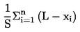
3. The following procedure is used for each of the pollutants given in paragraph 5.2.1. of the Regulation (see Figure 2):
Let:
|
L |
= |
the natural logarithm of the limit value for the pollutant; |
|
xi |
= |
the natural logarithm of the measurement for the i-th engine of the sample; |
|
s |
= |
an estimate of the production standard deviation (after taking the natural logarithm of the measurements); |
|
n |
= |
the current sample number. |
4. For each sample the sum of the standardised deviations to the limit is calculated using the following formula:
5. Then:
|
— |
if the test statistic result is greater than the pass decision number for the sample size given in table 3, a pass decision is reached for the pollutant; |
|
— |
if the test statistic result is less than the fail decision number for the sample size given in table 3, a fail decision is reached for the pollutant; |
|
— |
otherwise, an additional engine is tested according to paragraph 8.3.1. of the Regulation and the calculation procedure is applied to the sample increased by one more unit. |
Table 3
Pass and Fail decision numbers of appendix 1 Sampling Plan
Minimum sample size: 3
|
Cumulative number of engines tested (sample size) |
Pass decision number An |
Fail decision number Bn |
|
3 |
3,327 |
–4,724 |
|
4 |
3,261 |
–4,790 |
|
5 |
3,195 |
–4,856 |
|
6 |
3,129 |
–4,922 |
|
7 |
3,063 |
–4,988 |
|
8 |
2,997 |
–5,054 |
|
9 |
2,931 |
–5,120 |
|
10 |
2,865 |
–5,185 |
|
11 |
2,799 |
–5,251 |
|
12 |
2,733 |
–5,317 |
|
13 |
2,667 |
–5,383 |
|
14 |
2,601 |
–5,449 |
|
15 |
2,535 |
–5,515 |
|
16 |
2,469 |
–5,581 |
|
17 |
2,403 |
–5,647 |
|
18 |
2,337 |
–5,713 |
|
19 |
2,271 |
–5,779 |
|
20 |
2,205 |
–5,845 |
|
21 |
2,139 |
–5,911 |
|
22 |
2,073 |
–5,977 |
|
23 |
2,007 |
–6,043 |
|
24 |
1,941 |
–6,109 |
|
25 |
1,875 |
–6,175 |
|
26 |
1,809 |
–6,241 |
|
27 |
1,743 |
–6,307 |
|
28 |
1,677 |
–6,373 |
|
29 |
1,611 |
–6,439 |
|
30 |
1,545 |
–6,505 |
|
31 |
1,479 |
–6,571 |
|
32 |
–2,112 |
–2,112 |
Appendix 2
PROCEDURE FOR PRODUCTION CONFORMITY TESTING WHEN STANDARD DEVIATION IS UNSATISFACTORY OR UNAVAILABLE
1. This appendix describes the procedure to be used to verify production conformity for the emissions of pollutants when the manufacturer's production standard deviation is either unsatisfactory or unavailable.
2. With a minimum sample size of three engines, the sampling procedure is set so that the probability of a lot passing a test with 40 per cent of the engines defective is 0,95 (producer's risk = 5 per cent), while the probability of a lot being accepted with 65 per cent of the engines defective is 0,10 (consumer's risk = 10 per cent).
3. The values of the pollutants given in paragraph 5.2.1. of the Regulation are considered to be log normally distributed and should be transformed by taking their natural logarithms.
Let m0 and m denote the minimum and maximum sample size respectively (m0 = 3 and m = 32) and let n denote the current sample number.
4. If the natural logarithms of the values measured in the series are x1, x2, …, xi and L is the natural logarithm of the limit value for the pollutant, then, define
|
and, |
di = xi – L |
|
|
|
|
|
5. Table 4 shows values of the pass (An) and fail (Bn) decision numbers against current sample number. The test statistic result is the ratio  and must be used to determine whether the series has passed or failed as follows:
For m0 ≤ n ≤ m:
|
— |
pass the series if |
|
— |
fail the series if |
|
— |
take another measurement if |
6. Remarks:
The following recursive formulae are useful for calculating successive values of the test statistic:


Table 4
Pass and Fail decision numbers of appendix 2 Sampling Plan
Minimum sample size: 3
|
Cumulative number of engines tested (sample size) |
Pass decision number An |
Fail decision number Bn |
|
3 |
–0,80381 |
16,64743 |
|
4 |
–0,76339 |
7,68627 |
|
5 |
–0,72982 |
4,67136 |
|
6 |
–0,69962 |
3,25573 |
|
7 |
–0,67129 |
2,45431 |
|
8 |
–0,64406 |
1,94369 |
|
9 |
–0,61750 |
1,59105 |
|
10 |
–0,59135 |
1,33295 |
|
11 |
–0,56542 |
1,13566 |
|
12 |
–0,53960 |
0,97970 |
|
13 |
–0,51379 |
0,85307 |
|
14 |
–0,48791 |
0,74801 |
|
15 |
–0,46191 |
0,65928 |
|
16 |
–0,43573 |
0,58321 |
|
17 |
–0,40933 |
0,51718 |
|
18 |
–0,38266 |
0,45922 |
|
19 |
–0,35570 |
0,40788 |
|
20 |
–0,32840 |
0,36203 |
|
21 |
–0,30072 |
0,32078 |
|
22 |
–0,27263 |
0,28343 |
|
23 |
–0,24410 |
0,24943 |
|
24 |
–0,21509 |
0,21831 |
|
25 |
–0,18557 |
0,18970 |
|
26 |
–0,15550 |
0,16328 |
|
27 |
–0,12483 |
0,13880 |
|
28 |
–0,09354 |
0,11603 |
|
29 |
–0,06159 |
0,09480 |
|
30 |
–0,02892 |
0,07493 |
|
31 |
–0,00449 |
0,05629 |
|
32 |
0,03876 |
0,03876 |
Appendix 3
PROCEDURE FOR PRODUCTION CONFORMITY TESTING AT MANUFACTURER'S REQUEST
1. This appendix describes the procedure to be used to verify, at the manufacturer's request, production conformity for the emissions of pollutants.
2. With a minimum sample size of three engines, the sampling procedure is set so that the probability of a lot passing a test with 30 per cent of the engines defective is 0,90 (producer's risk = 10 per cent), while the probability of a lot being accepted with 65 per cent of the engines defective is 0,10 (consumer's risk = 10 per cent).
3. The following procedure is used for each of the pollutants given in paragraph 5.2.1. of the Regulation (see figure 2):
Let:
|
L |
= |
the limit value for the pollutant, |
|
xi |
= |
the value of the measurement for the i-th engine of the sample, |
|
n |
= |
the current sample number. |
4. Calculate for the sample the test statistic quantifying the number of non-conforming engines, i.e. xi ≥ L:
5. Then:
|
— |
if the test statistic is less than or equal to the pass decision number for the sample size given in table 5, a pass decision is reached for the pollutant; |
|
— |
if the test statistic is greater than or equal to the fail decision number for the sample size given in table 5, a fail decision is reached for the pollutant; |
|
— |
otherwise, an additional engine is tested according to paragraph 8.3.1. of the Regulation and the calculation procedure is applied to the sample increased by one more unit. |
In table 5 the pass and fail decision numbers are calculated by means of the International Standard ISO 8422:1991.
Table 5
Pass and Fail decision numbers of appendix 3 Sampling Plan
Minimum sample size: 3
|
Cumulative number of engines tested (sample size) |
Pass decision number |
Fail decision number |
|
3 |
— |
3 |
|
4 |
0 |
4 |
|
5 |
0 |
4 |
|
6 |
1 |
5 |
|
7 |
1 |
5 |
|
8 |
2 |
6 |
|
9 |
2 |
6 |
|
10 |
3 |
7 |
|
11 |
3 |
7 |
|
12 |
4 |
8 |
|
13 |
4 |
8 |
|
14 |
5 |
9 |
|
15 |
5 |
9 |
|
16 |
6 |
10 |
|
17 |
6 |
10 |
|
18 |
7 |
11 |
|
19 |
8 |
9 |
ANNEX 1
ESSENTIAL CHARACTERISTICS OF THE (PARENT) ENGINE AND INFORMATION CONCERNING THE CONDUCT OF TEST (9)
1. DESCRIPTION OF ENGINE
1.1. Manufacturer: …
1.2. Manufacturer's engine code: …
1.3. Cycle: four stroke/two stroke (10)
Number and arrangement of cylinders: …
1.4.1. Bore: … mm
1.4.2. Stroke: … mm
1.4.3. Firing order: …
1.5. Engine capacity: … cm3
1.6. Volumetric compression ratio (11): …
1.7. Drawing(s) of combustion chamber and piston crown: …
1.8. Minimum cross-sectional area of inlet and outlet ports: … cm2
1.9. Idling speed: … min–1
1.10. Maximum net power: … kW at … min–1
1.11. Maximum permitted engine speed: … min–1
1.12. Maximum net torque: … Nm at … min–1
1.13. Combustion system: compression ignition/positive ignition (10)
1.14. Fuel: Diesel/LPG/NG-H/NG-L/NG-HL/Ethanol (9)
Cooling system
Liquid
1.15.1.1. Nature of liquid: …
1.15.1.2. Circulating pump(s): yes/no (10)
1.15.1.3. Characteristics or make(s) and type(s) (if applicable): …
1.15.1.4. Drive ratio(s) (if applicable): …
Air
1.15.2.1. Blower: yes/no (10)
1.15.2.2. Characteristics or make(s) and type(s) (if applicable): …
1.15.2.3. Drive ratio(s) (if applicable): …
Temperature permitted by the manufacturer
1.16.1. Liquid cooling: Maximum temperature at outlet: … K
1.16.2. Air cooling: … Reference point: …
Maximum temperature at reference point: … K
1.16.3. Maximum temperature of the air at the outlet of the intake intercooler (if applicable) … K
1.16.4. Maximum exhaust temperature at the point in the exhaust pipe(s) adjacent to the outer flange(s) of the exhaust manifold(s)
or turbocharger(s): … K
1.16.5. Fuel temperature: min. … K, max. … K
for diesel engines at injection pump inlet, for gas fuelled engines at pressure regulator final stage.
1.16.6. Fuel pressure: min. … kPa, max. … kPa
at pressure regulator final stage, NG fuelled gas engines only.
1.16.7. Lubricant temperature: min. … K, max. … K
Pressure charger: yes/no (10)
1.17.1. Make: …
1.17.2. Type: …
1.17.3. Description of the system
(e.g. max. charge pressure, wastegate, if applicable): …
1.17.4. Intercooler: yes/no (10)
1.18. Intake system
Maximum allowable intake depression at rated engine speed and at 100 per cent load as specified in and under the operating conditions
of Regulation No 24 … kPa
1.19. Exhaust system
Maximum allowable exhaust back pressure at rated engine speed and at 100 per cent load as specified in and under the operating conditions
of Regulation No 24 … kPa
Exhaust system volume: … dm3
2. MEASURES TAKEN AGAINST AIR POLLUTION
2.1. Device for recycling crankcase gases (description and drawings): …
…
Additional anti-pollution devices (if any, and if not covered by another heading)
Catalytic converter: yes/no (10)
2.2.1.1. Make(s): …
2.2.1.2. Type(s): …
2.2.1.3. Number of catalytic converters and elements: …
2.2.1.4. Dimensions, shape and volume of the catalytic converter(s): …
2.2.1.5. Type of catalytic action: …
2.2.1.6. Total charge of precious metals: …
2.2.1.7. Relative concentration: …
2.2.1.8. Substrate (structure and material): …
2.2.1.9. Cell density: …
2.2.1.10. Type of casing for the catalytic converter(s): …
2.2.1.11. Location of the catalytic converter(s) (place and reference distance in the exhaust line): …
…
Oxygen sensor: yes/no (10)
2.2.2.1. Make(s): …
2.2.2.2. Type: …
2.2.2.3. Location: …
Air injection: yes/no (10)
2.2.3.1. Type (pulse air, air pump, etc.): …
EGR: yes/no (10)
2.2.4.1. Characteristics (flow rate, etc.): …
Particulate trap: yes/no (10)
2.2.5.1. Dimensions, shape and capacity of the particulate trap: …
2.2.5.2. Type and design of the particulate trap: …
2.2.5.3. Location (reference distance in the exhaust line): …
2.2.5.4. Method or system of regeneration, description and/or drawing: …
Other systems: yes/no (10)
2.2.6.1. Description and operation: …
3. FUEL FEED
Diesel engines
3.1.1. Feed pump
Pressure (11): … kPa or characteristic diagram (10): …
Injection system
Pump
3.1.2.1.1. Make(s): …
3.1.2.1.2. Type(s): …
3.1.2.1.3. Delivery: … mm3 (11) per stroke at engine speed of … min–1 at full injection, or characteristic diagram (10) (11): …
…
Mention the method used: On engine/on pump bench (10)
If boost control is supplied, state the characteristic fuel delivery and boost pressure versus engine speed.
Injection advance
3.1.2.1.4.1. Injection advance curve (11): …
3.1.2.1.4.2. Static injection timing (11): …
Injection piping
3.1.2.2.1. Length: … mm
3.1.2.2.2. Internal diameter: … mm
Injector(s)
3.1.2.3.1. Make(s): …
3.1.2.3.2. Type(s): …
3.1.2.3.3. ‘Opening pressure’: … kPa (11)
or characteristic diagram (10) (11): …
Governor
3.1.2.4.1. Make(s): …
3.1.2.4.2. Type(s): …
3.1.2.4.3. Speed at which cut-off starts under full load: … min–1
3.1.2.4.4. Maximum no-load speed: … min–1
3.1.2.4.5. Idling speed: … min–1
Cold start system
3.1.3.1. Make(s): …
3.1.3.2. Type(s): …
3.1.3.3. Description: …
Auxiliary starting aid: …
3.1.3.4.1. Make: …
3.1.3.4.2. Type: …
Gas fuelled engines (12)
3.2.1. Fuel: Natural gas/LPG (10)
Pressure regulator(s) or vaporiser/pressure regulator(s) (11)
3.2.2.1. Make(s): …
3.2.2.2. Type(s): …
3.2.2.3. Number of pressure reduction stages: …
3.2.2.4. Pressure in final stage: min … kPa, max. … kPa
3.2.2.5. Number of main adjustment points: …
3.2.2.6. Number of idle adjustment points: …
3.2.2.7. Approval number according to Reg. No: …
Fuelling system: mixing unit/gas injection/liquid injection/direct injection (10)
3.2.3.1. Mixture strength regulation: …
3.2.3.2. System description and/or diagram and drawings: …
3.2.3.3. Approval number according to Regulation No …
Mixing unit
3.2.4.1. Number: …
3.2.4.2. Make(s): …
3.2.4.3. Type(s): …
3.2.4.4. Location: …
3.2.4.5. Adjustment possibilities: …
3.2.4.6. Approval number according to Regulation No …
Inlet manifold injection
3.2.5.1. Injection: single point/multi-point (10)
3.2.5.2. Injection: continuous/simultaneously timed/sequentially timed (10)
Injection equipment
3.2.5.3.1. Make(s): …
3.2.5.3.2. Type(s): …
3.2.5.3.3. Adjustment possibilities: …
3.2.5.3.4. Approval number according to Regulation No …
Supply pump (if applicable): …
3.2.5.4.1. Make(s): …
3.2.5.4.2. Type(s): …
3.2.5.4.3. Approval number according to Regulation No …
Injector(s): …
3.2.5.5.1. Make(s): …
3.2.5.5.2. Type(s): …
3.2.5.5.3. Approval number according to Regulation No …
Direct injection
Injection pump/pressure regulator (10)
3.2.6.1.1. Make(s): …
3.2.6.1.2. Type(s): …
3.2.6.1.3. Injection timing: …
3.2.6.1.4. Approval number according to Regulation No …
Injector(s)
3.2.6.2.1. Make(s): …
3.2.6.2.2. Type(s): …
3.2.6.2.3. Opening pressure or characteristic diagram (11): …
3.2.6.2.4. Approval number according to Regulation No …
Electronic control unit (ECU)
3.2.7.1. Make(s): …
3.2.7.2. Type(s): …
3.2.7.3. Adjustment possibilities: …
NG fuel-specific equipment
Variant 1 (only in the case of approvals of engines for several specific fuel compositions)
3.2.8.1.1. Fuel composition:
|
methane (CH4): |
basis: … %mole |
min … %mole |
max … %mole |
|
ethane (C2H6): |
basis: … %mole |
min … %mole |
max … %mole |
|
propane (C3H8): |
basis: … %mole |
min … %mole |
max … %mole |
|
butane (C4H10): |
basis: … %mole |
min … %mole |
max … %mole |
|
C5/C5+: |
basis: … %mole |
min … %mole |
max … %mole |
|
oxygen (O2): |
basis: … %mole |
min … %mole |
max … %mole |
|
inert (N2, He etc): |
basis: … %mole |
min … %mole |
max … %mole |
Injector(s)
3.2.8.1.2.1. Make(s):
3.2.8.1.2.2. Type(s):
3.2.8.1.3. Others (if applicable)
3.2.8.2. Variant 2 (only in the case of approvals for several specific fuel compositions)
4. VALVE TIMING
4.1. Maximum lift of valves and angles of opening and closing in relation to dead centres or equivalent data …
4.2. Reference and/or setting ranges (10): …
5. IGNITION SYSTEM (SPARK IGNITION ENGINES ONLY)
5.1. Ignition system type:
common coil and plugs/individual coil and plugs/coil on plug/other (specify) (10)
Ignition control unit
5.2.1. Make(s): …
5.2.2. Type(s): …
5.3. Ignition advance curve/advance map (10) (11): …
5.4. Ignition timing (11): … degrees before TDC at a speed of … min–1 and a MAP of … kPa
Spark plugs
5.5.1. Make(s): …
5.5.2. Type(s): …
5.5.3. Gap setting: … mm
Ignition coil(s)
5.6.1. Make(s): …
5.6.2. Type(s): …
6. ENGINE-DRIVEN EQUIPMENT
The engine must be submitted for testing with the auxiliaries needed for operating the engine (e.g. fan, water pump, etc.), as specified in and under the operating conditions of Regulation No 24.
6.1. Auxiliaries to be fitted for the test
If it is impossible or inappropriate to install the auxiliaries on the test bench, the power absorbed by them must be determined and subtracted from the measured engine power over the whole operating area of the test cycle(s).
6.2. Auxiliaries to be removed for the test
Auxiliaries needed only for the operation of the vehicle (e.g. air compressor, air-conditioning system etc.) must be removed for the test. Where the auxiliaries cannot be removed, the power absorbed by them may be determined and added to the measured engine power over the whole operating area of the test cycle(s).
7. ADDITIONAL INFORMATION ON TEST CONDITIONS
Lubricant used
7.1.1. Make: …
7.1.2. Type: …
(State percentage of oil in mixture if lubricant and fuel are mixed): …
Engine-driven equipment (if applicable)
The power absorbed by the auxiliaries needs only be determined,
|
— |
if auxiliaries needed for operating the engine, are not fitted to the engine and/or |
|
— |
if auxiliaries not needed for operating the engine, are fitted to the engine. |
7.2.1. Enumeration and identifying details: …
7.2.2. Power absorbed at various indicated engine speeds:
|
Equipment |
Power absorbed (kW) at various engine speeds |
||||||
|
Idle |
Low Speed |
High Speed |
Speed A (13) |
Speed B (13) |
Speed C (13) |
Ref. Speed (14) |
|
|
P(a) Auxiliaries needed for operating the engine (to be subtracted from measured engine power) see item 6.1. |
|
|
|
|
|
|
|
|
P(b) Auxiliaries not needed for operating the engine (to be added to measured engine power) see item 6.2. |
|
|
|
|
|
|
|
8. ENGINE PERFORMANCE
8.1. Engine speeds (15)
Low speed (nlo): … min–1
High speed (nhi): … min–1
for ESC and ELR Cycles
Idle: … min–1
Speed A: … min–1
Speed B: … min–1
Speed C: … min–1
for ETC cycle
Reference speed: … min–1
8.2. Engine power (measured in accordance with the provisions of Regulation No 24) in kW
|
|
Engine speed |
||||||||
|
Idle |
Speed A (13) |
Speed B (13) |
Speed C (13) |
Ref. Speed (14) |
|||||
|
P(m) Power measured on test bed |
|
|
|
|
|
||||
|
P(a) Power absorbed by auxiliaries to be fitted for test (item 6.1)
|
0 |
0 |
0 |
0 |
0 |
||||
|
P(b) Power absorbed by auxiliaries to be removed for test (item 6.2)
|
0 |
0 |
0 |
0 |
0 |
||||
|
P(n) Net engine power = P(m) – P(a) + P(b) |
|
|
|
|
|
||||
Dynamometer settings (kW)
The dynamometer settings for the ESC and ELR tests and for the reference cycle of the ETC test must be based upon the net engine power P(n) of paragraph 8.2. It is recommended to install the engine on the test bed in the net condition. In this case, P(m) and P(n) are identical. If it is impossible or inappropriate to operate the engine under net conditions, the dynamometer settings must be corrected to net conditions using the above formula.
8.3.1. ESC and ELR Tests
The dynamometer settings must be calculated according to the formula in annex 4, appendix 1, paragraph 1.2.
|
Per cent load |
Engine speed |
|||
|
Idle |
Speed A |
Speed B |
Speed C |
|
|
10 |
— |
|
|
|
|
25 |
— |
|
|
|
|
50 |
— |
|
|
|
|
75 |
— |
|
|
|
|
100 |
|
|
|
|
8.3.2. ETC Test
If the engine is not tested under net conditions, the correction formula for converting the measured power or measured cycle work, as determined according to annex 4, appendix 2, paragraph 2., to net power or net cycle work must be submitted by the engine manufacturer for the whole operating area of the cycle, and approved by the Technical Service.
ANNEX 1
Appendix 1
CHARACTERISTICS OF THE ENGINE-RELATED VEHICLE PARTS
1. Intake system depression at rated engine speed and
at 100 per cent load: … kPa
2. Exhaust system back pressure at rated engine speed and
at 100 per cent load: … kPa
3. Volume of exhaust system: … cm3
4. Power absorbed by the auxiliaries needed for operating the engine as specified in and under the operation conditions of Regulation No 24
|
Equipment |
Power absorbed (kW) at various engine speeds |
||||||
|
Idle |
Low Speed |
High Speed |
Speed A (16) |
Speed B (16) |
Speed C (16) |
Ref. Speed (17) |
|
|
P(a) Auxiliaries needed for operating the engine (to be subtracted from measured engine power) see annex 1, item 6.1. |
|
|
|
|
|
|
|
ANNEX 1
Appendix 2
ESSENTIAL CHARACTERISTICS OF THE ENGINE FAMILY
1. COMMON PARAMETERS
1.1. Combustion cycle: …
1.2. Cooling medium: …
1.3. Number of cylinders (18): …
1.4. Individual cylinder displacement: …
1.5. Method of air aspiration: …
1.6. Combustion chamber type/design: …
1.7. Valve and porting — configuration, size and number: …
…
1.8. Fuel system: …
1.9. Ignition system (gas engines): …
1.10. Miscellaneous features:
|
— |
charge cooling system (18): … |
|
— |
exhaust gas recirculation (18): … |
|
— |
water injection/emulsion (18): … |
|
— |
air injection (18): … |
1.11. Exhaust after-treatment (18): …
Proof of identical (or lowest for the parent engine) ratio:
system capacity/fuel delivery per stroke, pursuant to diagram number(s): …
2. ENGINE FAMILY LISTING
Name of diesel engine family: …
2.1.1. Specification of engines within this family:
|
|
|
|
|
|
Parent Engine |
|
Engine Type |
|
|
|
|
|
|
No of cylinders |
|
|
|
|
|
|
Rated speed (min–1) |
|
|
|
|
|
|
Fuel delivery per stroke (mm3) |
|
|
|
|
|
|
Rated net power (kW) |
|
|
|
|
|
|
Maximum torque speed (min–1) |
|
|
|
|
|
|
Fuel delivery per stroke (mm3) |
|
|
|
|
|
|
Maximum torque (Nm) |
|
|
|
|
|
|
Low idle speed (min–1) |
|
|
|
|
|
|
Cylinder displacement (in % of parent engine) |
|
|
|
|
100 |
Name of gas engine family: …
2.2.1. Specification of engines within this family:
|
|
|
|
|
|
Parent Engine |
|
Engine Type |
|
|
|
|
|
|
No of cylinders |
|
|
|
|
|
|
Rated speed (min–1) |
|
|
|
|
|
|
Fuel delivery per stroke (mm3) |
|
|
|
|
|
|
Rated net power (kW) |
|
|
|
|
|
|
Maximum torque speed (min–1) |
|
|
|
|
|
|
Fuel delivery per stroke (mm3) |
|
|
|
|
|
|
Maximum torque (Nm) |
|
|
|
|
|
|
Low idle speed (min–1) |
|
|
|
|
|
|
Cylinder displacement (in % of parent engine) |
|
|
|
|
100 |
|
Spark timing |
|
|
|
|
|
|
EGR flow |
|
|
|
|
|
|
Air pump yes/no |
|
|
|
|
|
|
Air pump actual flow |
|
|
|
|
|
ANNEX 1
Appendix 3
ESSENTIAL CHARACTERISTICS OF THE ENGINE TYPE WITHIN THE FAMILY (19)
1. DESCRIPTION OF ENGINE
1.1. Manufacturer: …
1.2. Manufacturer's engine code: …
1.3. Cycle: four stroke/two stroke (20)
Number and arrangement of cylinders: …
1.4.1. Bore: … mm
1.4.2. Stroke: … mm
1.4.3. Firing order: …
1.5. Engine capacity: … cm3
1.6. Volumetric compression ratio (21): …
1.7. Drawing(s) of combustion chamber and piston crown: …
…
1.8. Minimum cross-sectional area of inlet and outlet ports: … cm2
1.9. Idling speed: … min–1
1.10. Maximum net power: … kW at … min–1
1.11. Maximum permitted engine speed: … min–1
1.12. Maximum net torque: … Nm at … min–1
1.13. Combustion system: compression ignition/positive ignition (20)
1.14. Fuel: Diesel/LPG/NG-H/NG-L/NG-HL/Ethanol (19)
Cooling system
Liquid
1.15.1.1. Nature of liquid: …
1.15.1.2. Circulating pump(s): yes/no (20)
1.15.1.3. Characteristics or make(s) and type(s) (if applicable): …
…
1.15.1.4. Drive ratio(s) (if applicable): …
Air
1.15.2.1. Blower: yes/no (20)
1.15.2.2. Characteristics or make(s) and type(s) (if applicable): …
…
1.15.2.3. Drive ratio(s) (if applicable): …
Temperature permitted by the manufacturer
1.16.1. Liquid cooling: Maximum temperature at outlet: … K
1.16.2. Air cooling: Reference point: …
Maximum temperature at reference point: … K
1.16.3. Maximum temperature of the air at the outlet of the intake intercooler (if applicable): … K
1.16.4. Maximum exhaust temperature at the point in the exhaust pipe(s) adjacent to the outer flange(s) of the exhaust manifold(s) or turbocharger(s): … K
1.16.5. Fuel temperature: min. … K, max. … K
for diesel engines at injection pump inlet, for gas fuelled engines at pressure regulator final stage
1.16.6. Fuel pressure: min. … kPa, max. … kPa
at pressure regulator final stage, NG fuelled gas engines only
1.16.7. Lubricant temperature: min. … K, max … K
Pressure charger: yes/no (20)
1.17.1. Make: …
1.17.2. Type: …
1.17.3. Description of the system (e.g. max. charge pressure, wastegate, if applicable): …
1.17.4. Intercooler: yes/no (20)
1.18. Intake system
Maximum allowable intake depression at rated engine speed and at 100 per cent load as specified in and under the operating conditions of Regulation No 24: … kPa
1.19. Exhaust system
Maximum allowable exhaust back pressure at rated engine speed and at 100 per cent load as specified in and under the operating conditions of Regulation No 24: … kPa
Exhaust system volume: … cm3
2. MEASURES TAKEN AGAINST AIR POLLUTION
2.1. Device for recycling crankcase gases (description and drawings): …
Additional anti-pollution devices (if any, and if not covered by another heading)
Catalytic converter: yes/no (20)
2.2.1.1. Number of catalytic converters and elements: …
2.2.1.2. Dimensions, shape and volume of the catalytic converter(s): …
…
2.2.1.3. Type of catalytic action: …
2.2.1.4. Total charge of precious metals: …
2.2.1.5. Relative concentration: …
2.2.1.6. Substrate (structure and material): …
2.2.1.7. Cell density: …
2.2.1.8. Type of casing for the catalytic converter(s): …
2.2.1.9. Location of the catalytic converter(s) (place and reference distance in the exhaust line): …
…
Oxygen sensor: yes/no (20)
2.2.2.1. Type: …
Air injection: yes/no (20)
2.2.3.1. Type (pulse air, air pump, etc.): …
EGR: yes/no (20)
2.2.4.1. Characteristics (flow rate etc.): …
Particulate trap: yes/no (20)
2.2.5.1. Dimensions, shape and capacity of the particulate trap: …
…
2.2.5.2. Type and design of the particulate trap: …
2.2.5.3. Location (reference distance in the exhaust line): …
2.2.5.4. Method or system of regeneration, description and/or drawing: …
…
Other systems: yes/no (20)
2.2.6.1. Description and operation: …
3. FUEL FEED
Diesel engines
3.1.1. Feed pump
Pressure (21): … kPa or characteristic diagram (20): …
…
Injection system
Pump
3.1.2.1.1. Make(s): …
3.1.2.1.2. Type(s): …
3.1.2.1.3. Delivery: … mm3 (21) per stroke at engine speed of … min–1 at full injection, or characteristic diagram (20) (21): …
…
Mention the method used: On engine/on pump bench (20)
If boost control is supplied, state the characteristic fuel delivery and boost pressure versus engine speed.
Injection advance
3.1.2.1.4.1. Injection advance curve (21): …
3.1.2.1.4.2. Static injection timing (21): …
Injection piping
3.1.2.2.1. Length: … mm
3.1.2.2.2. Internal diameter: … mm
Injector(s)
3.1.2.3.1. Make(s): …
3.1.2.3.2. Type(s): …
3.1.2.3.3. ‘Opening pressure’: … kPa (21)
or characteristic diagram (20) (21): …
Governor
3.1.2.4.1. Make(s): …
3.1.2.4.2. Type(s): …
3.1.2.4.3. Speed at which cut-off starts under full load: … min–1
3.1.2.4.4. Maximum no-load speed: … min–1
3.1.2.4.5. Idling speed: … min–1
Cold start system
3.1.3.1. Make(s): …
3.1.3.2. Type(s): …
3.1.3.3. Description: …
Auxiliary starting aid: …
3.1.3.4.1. Make: …
3.1.3.4.2. Type: …
Gas fuelled engines
3.2.1. Fuel: Natural gas/LPG (20)
Pressure regulator(s) or vaporiser/pressure regulator(s) (20)
3.2.2.1. Make(s): …
3.2.2.2. Type(s): …
3.2.2.3. Number of pressure reduction stages: …
3.2.2.4. Pressure in final stage: min. … kPa, max. … kPa
3.2.2.5. Number of main adjustment points: …
3.2.2.6. Number of idle adjustment points: …
3.2.2.7. Approval number: …
Fuelling system: mixing unit/gas injection/liquid injection/direct injection (20)
3.2.3.1. Mixture strength regulation: …
3.2.3.2. System description and/or diagram and drawings: …
…
3.2.3.3. Approval number: …
Mixing unit
3.2.4.1. Number: …
3.2.4.2. Make(s): …
3.2.4.3. Type(s): …
3.2.4.4. Location: …
3.2.4.5. Adjustment possibilities: …
3.2.4.6. Approval number: …
Inlet manifold injection
3.2.5.1. Injection: single point/multi-point (20)
3.2.5.2. Injection: continuous/simultaneously timed/sequentially timed (20)
Injection equipment
3.2.5.3.1. Make(s): …
3.2.5.3.2. Type(s): …
3.2.5.3.3. Adjustment possibilities: …
3.2.5.3.4. Approval number: …
Supply pump (if applicable): …
3.2.5.4.1. Make(s): …
3.2.5.4.2. Type(s): …
3.2.5.4.3. Approval number: …
Injector(s): …
3.2.5.5.1. Make(s): …
3.2.5.5.2. Type(s): …
3.2.5.5.3. Approval number: …
Direct injection
Injection pump/pressure regulator (20)
3.2.6.1.1. Make(s): …
3.2.6.1.2. Type(s): …
3.2.6.1.3. Injection timing: …
3.2.6.1.4. Approval number: …
Injector(s)
3.2.6.2.1. Make(s): …
3.2.6.2.2. Type(s): …
3.2.6.2.3. Opening pressure or characteristic diagram (21): …
…
3.2.6.2.4. Approval number: …
Electronic control unit (ECU)
3.2.7.1. Make(s): …
3.2.7.2. Type(s): …
3.2.7.3. Adjustment possibilities: …
NG fuel-specific equipment
Variant 1 (only in the case of approvals of engines for several specific fuel compositions)
3.2.8.1.1. Fuel composition:
|
methane (CH4): |
basis: … %mole |
min. … %mole |
max. … %mole |
|
ethane (C2H6): |
basis: … %mole |
min. … %mole |
max. … %mole |
|
propane (C3H8): |
basis: … %mole |
min. … %mole |
max. … %mole |
|
butane (C4H10): |
basis: … %mole |
min. … %mole |
max. … %mole |
|
C5/C5+: |
basis: … %mole |
min. … %mole |
max. … %mole |
|
oxygen (O2): |
basis: … %mole |
min. … %mole |
max. … %mole |
|
inert (N2, He etc): |
basis: … %mole |
min. … %mole |
max. … %mole |
Injector(s)
3.2.8.1.2.1. Make(s): …
3.2.8.1.2.2. Type(s): …
3.2.8.1.3. Others (if applicable)
3.2.8.2. Variant 2 (only in the case of approvals for several specific fuel compositions)
4. VALVE TIMING
4.1. Maximum lift of valves and angles of opening and closing in relation to dead centres of equivalent data: …
…
4.2. Reference and/or setting ranges (20): …
…
5. IGNITION SYSTEM (SPARK IGNITION ENGINES ONLY)
5.1. Ignition system type: common coil and plugs/individual coil and plugs/coil on plug/other (specify) (20)
Ignition control unit
5.2.1. Make(s): …
5.2.2. Type(s): …
5.3. Ignition advance curve/advance map (20) (21): …
…
5.4. Ignition timing (21): … degrees before TDC at a speed of … min–1 and a MAP of … kPa
Spark plugs
5.5.1. Make(s): …
5.5.2. Type(s): …
5.5.3. Gap setting: … mm
Ignition coil(s)
5.6.1. Make(s): …
5.6.2. Type(s): …
ANNEX 2A


ANNEX 2B


ANNEX 3
ARRANGEMENTS OF APPROVAL MARKS
(See paragraph 4.6. of this Regulation)
APPROVAL ‘I’ (Row A).
(See paragraph 4.6.3. of this Regulation)
Model A
Engines approved to Row A emission limits and operating on diesel or liquefied petroleum gas (LPG) fuel.

Model B
Engines approved to Row A emission limits and operating on natural gas (NG) fuel. The suffix after the national symbol indicates the fuel qualification determined in accordance with paragraph 4.6.3.1. of this Regulation.

The above approval marks affixed to an engine/vehicle show that the engine/vehicle type concerned has been approved in the United Kingdom (E11) pursuant to Regulation No 49 and under approval number 042439. This approval indicates that the approval was given in accordance with the requirements of Regulation No 49 with the 04 series of amendments incorporated and satisfying the relevant limits detailed in paragraph 5.2.1. of this Regulation.
APPROVAL ‘II’ (Row B1).
(See paragraph 4.6.3. of this Regulation)
Model C
Engines approved to Row B1 emission limits and operating on diesel or liquefied petroleum gas (LPG) fuel.

Model D
Engines approved to Row B1 emission limits and operating on natural gas (NG) fuel. The suffix after the national symbol indicates the fuel qualification determined in accordance with paragraph 4.6.3.1. of this Regulation.

The above approval mark affixed to an engine/vehicle shows that the engine/vehicle type concerned has been approved in the United Kingdom (E11) pursuant to Regulation No 49 and under approval number 042439. This approval indicates that the approval was given in accordance with the requirements of Regulation No 49 with the 04 series of amendments incorporated and satisfying the relevant limits detailed in paragraph 5.2.1. of this Regulation.
APPROVAL ‘III’ (Row B2).
(See paragraph 4.6.3. of this Regulation)
Model E
Engines approved to Row B2 emission limits and operating on diesel or liquefied petroleum gas (LPG) fuel.

Model F
Engines approved to Row B2 emission limits and operating on natural gas (NG) fuel. The suffix after the national symbol indicates the fuel qualification determined in accordance with paragraph 4.6.3.1. of this Regulation.

The above approval mark affixed to an engine/vehicle shows that the engine/vehicle type concerned has been approved in the United Kingdom (E11) pursuant to Regulation No 49 and under approval number 042439. This approval indicates that the approval was given in accordance with the requirements of Regulation No 49 with the 04 series of amendments incorporated and satisfying the relevant limits detailed in paragraph 5.2.1. of this Regulation.
APPROVAL ‘IV’ (Row C).
(See paragraph 4.6.3. of this Regulation)
Model G
Engines approved to Row C emission limits and operating on diesel or liquefied petroleum gas (LPG) fuel.

Model H
Engines approved to Row C emission limits and operating on natural gas (NG) fuel. The suffix after the national symbol indicates the fuel qualification determined in accordance with paragraph 4.6.3.1. of this Regulation.

The above approval mark affixed to an engine/vehicle shows that the engine/vehicle type concerned has been approved in the United Kingdom (E11) pursuant to Regulation No 49 and under approval number 042439. This approval indicates that the approval was given in accordance with the requirements of Regulation No 49 with the 04 series of amendments incorporated and satisfying the relevant limits detailed in paragraph 5.2.1. of this Regulation.
ENGINE/VEHICLE APPROVED TO ONE OR MORE REGULATIONS
(See paragraph 4.7. of this Regulation)
Model I

The above approval mark affixed to an engine/vehicle shows that the engine/vehicle type concerned has been approved in the United Kingdom (E11) pursuant to Regulation No 49 (emission level IV) and Regulation No 24 (22). The first two digits of the approval numbers indicate that, at the dates when the respective approvals were given, Regulation No 49 included the 04 series of amendments, and Regulation No 24 the 03 series of amendments.
ANNEX 4
TEST PROCEDURE
1. INTRODUCTION
This annex describes the methods of determining emissions of gaseous components, particulates and smoke from the engines to be tested. Three test cycles are described that must be applied according to the provisions of the Regulation, paragraph 5.2:
1.1.1. the ESC which consists of a steady state 13-mode cycle,
1.1.2. the ELR which consists of transient load steps at different speeds, which are integral parts of one test procedure, and are run concurrently;
1.1.3. the ETC which consists of a second-by-second sequence of transient modes.
1.2. The test must be carried out with the engine mounted on a test bench and connected to a dynamometer.
1.3. Measurement principle
The emissions to be measured from the exhaust of the engine include the gaseous components (carbon monoxide, total hydrocarbons for diesel engines on the ESC test only; non-methane hydrocarbons for diesel and gas engines on the ETC test only; methane for gas engines on the ETC test only and oxides of nitrogen), the particulates (diesel engines, gas engines at stage C only) and smoke (diesel engines on the ELR test only). Additionally, carbon dioxide is often used as a tracer gas for determining the dilution ratio of partial and full flow dilution systems. Good engineering practice recommends the general measurement of carbon dioxide as an excellent tool for the detection of measurement problems during the test run.
1.3.1. ESC test
During a prescribed sequence of warmed-up engine operating conditions the amounts of the above exhaust emissions must be examined continuously by taking a sample from the raw exhaust gas. The test cycle consists of a number of speed and power modes, which cover the typical operating range of diesel engines. During each mode the concentration of each gaseous pollutant, exhaust flow and power output must be determined, and the measured values weighted. The particulate sample must be diluted with conditioned ambient air. One sample over the complete test procedure must be taken, and collected on suitable filters. The grams of each pollutant emitted per kilowatt-hour (kWh) must be calculated as described in appendix 1 to this annex. Additionally, NOx must be measured at three test points within the control area selected by the Technical Service (23) and the measured values compared to the values calculated from those modes of the test cycle enveloping the selected test points. The NOx control check ensures the effectiveness of the emission control of the engine within the typical engine operating range.
1.3.2. ELR test
During a prescribed load response test, the smoke of a warmed-up engine must be determined by means of an opacimeter. The test consists of loading the engine at constant speed from 10 per cent to 100 per cent load at three different engine speeds. Additionally, a fourth load step selected by the Technical Service (23) must be run, and the value compared to the values of the previous load steps. The smoke peak must be determined using an averaging algorithm, as described in appendix 1 to this annex.
1.3.3. ETC test
During a prescribed transient cycle of warmed-up engine operating conditions, which is based closely on road-type-specific driving patterns of heavy-duty engines installed in trucks and buses, the above pollutants must be examined after diluting the total exhaust gas with conditioned ambient air. Using the engine torque and speed feedback signals of the engine dynamometer, the power must be integrated with respect to time of the cycle resulting in the work produced by the engine over the cycle. The concentration of NOx and HC must be determined over the cycle by integration of the analyser signal. The concentration of CO, CO2, and NMHC may be determined by integration of the analyser signal or by bag sampling. For particulates, a proportional sample must be collected on suitable filters. The diluted exhaust gas flow rate must be determined over the cycle to calculate the mass emission values of the pollutants. The mass emission values must be related to the engine work to get the grams of each pollutant emitted per kilowatt-hour (kWh), as described in appendix 2 to this annex.
2. TEST CONDITIONS
2.1. Engine test conditions
2.1.1. The absolute temperature (Ta) of the engine air at the inlet to the engine expressed in Kelvins, and the dry atmospheric pressure (ps), expressed in kPa must be measured and the parameter F must be determined according to the following provisions:
|
(a) |
for diesel engines: Naturally aspirated and mechanically supercharged engines: 
Turbocharged engines with or without cooling of the intake air: 
|
|
(b) |
for gas engines: 
|
2.1.2. Test validity
For a test to be recognised as valid, the parameter F must be such that:
0,96 ≤ F ≤ 1,06
2.2. Engines with charge air cooling
The charge air temperature must be recorded and must be, at the speed of the declared maximum power and full load, within ± 5 K of the maximum charge air temperature specified in annex 1, appendix 1, paragraph 1.16.3. The temperature of the cooling medium must be at least 293 K (20 °C).
If a test shop system or external blower is used, the charge air temperature must be within ± 5 K of the maximum charge air temperature specified in annex 1, paragraph 1.16.3. at the speed of the declared maximum power and full load. The setting of the charge air cooler for meeting the above conditions must be used for the whole test cycle.
2.3. Engine air intake system
An engine air intake system must be used presenting an air intake restriction within ± 100 Pa of the upper limit of the engine operating at the speed at the declared maximum power and full load.
2.4. Engine exhaust system
An exhaust system must be used presenting an exhaust back pressure within ±1 000 Pa of the upper limit of the engine operating at the speed of declared maximum power and full load and a volume within ± 40 per cent of that specified by the manufacturer. A test shop system may be used, provided it represents actual engine operating conditions. The exhaust system must conform to the requirements for exhaust gas sampling, as set out in annex 4, appendix 4, paragraph 3.4. and in annex 4, appendix 6, paragraph 2.2.1., EP and paragraph 2.3.1., EP.
If the engine is equipped with an exhaust after-treatment device, the exhaust pipe must have the same diameter as found in-use for at least 4 pipe diameters upstream to the inlet of the beginning of the expansion paragraph containing the after-treatment device. The distance from the exhaust manifold flange or turbocharger outlet to the exhaust after-treatment device must be the same as in the vehicle configuration or within the distance specifications of the manufacturer. The exhaust back-pressure or restriction must follow the same criteria as above, and may be set with a valve. The after-treatment container may be removed during dummy tests and during engine mapping, and replaced with an equivalent container having an inactive catalyst support.
2.5. Cooling system
An engine cooling system with sufficient capacity to maintain the engine at normal operating temperatures prescribed by the manufacturer must be used.
2.6. Lubricating oil
Specifications of the lubricating oil used for the test must be recorded and presented with the results of the test, as specified in annex 1, paragraph 7.1.
2.7. Fuel
The fuel must be the reference fuel specified in annexes 5, 6 or 7.
The fuel temperature and measuring point must be specified by the manufacturer within the limits given in annex 1, paragraph 1.16.5. The fuel temperature must not be lower than 306 K (33 °C). If not specified, it must be 311 K ± 5 K (38 °C ± 5 °C) at the inlet to the fuel supply.
For NG and LPG fuelled engines, the fuel temperature and measuring point must be within the limits given in annex 1, paragraph 1.16.5. or in annex 1, appendix 3, paragraph 1.16.5. in cases where the engine is not a parent engine.
2.8. Testing of exhaust after-treatment systems
If the engine is equipped with an exhaust after-treatment system, the emissions measured on the test cycle(s) must be representative of the emissions in the field. If this cannot be achieved with one single test cycle (e.g. for particulate filters with periodic regeneration), several test cycles must be conducted and the test results averaged and/or weighted. The exact procedure must be agreed by the engine manufacturer and the Technical Service based upon good engineering judgement.
ANNEX 4
Appendix 1
ESC AND ELR TEST CYCLES
1. ENGINE AND DYNAMOMETER SETTINGS
1.1. Determination of engine speeds A, B and C
The engine speeds A, B and C must be declared by the manufacturer in accordance with the following provisions:
The high speed nhi must be determined by calculating 70 per cent of the declared maximum net power P(n), as determined in annex 1, appendix 1, paragraph 8.2. The highest engine speed where this power value occurs on the power curve is defined as nhi.
The low speed nlo must be determined by calculating 50 per cent of the declared maximum net power P(n), as determined in annex 1, appendix 1, paragraph 8.2. The lowest engine speed where this power value occurs on the power curve is defined as nlo.
The engine speeds A, B and C must be calculated as follows:
|
Speed A |
= |
nlo + 25 % (nhi – nlo) |
|
Speed B |
= |
nlo + 50 % (nhi – nlo) |
|
Speed C |
= |
nlo + 75 % (nhi – nlo) |
The engine speeds A, B and C may be verified by either of the following methods:
|
(a) |
Additional test points must be measured during engine power approval according to Regulation No 24 for an accurate determination of nhi and nlo. The maximum power, nhi and nlo must be determined from the power curve, and engine speeds A, B and C must be calculated according to the above provisions. |
|
(b) |
The engine must be mapped along the full load curve, from maximum no load speed to idle speed, using at least 5 measurement points per 1 000 min–1 intervals and measurement points within ± 50 min–1 of the speed at declared maximum power. The maximum power, nhi and nlo must be determined from this mapping curve, and engine speeds A, B and C must be calculated according to the above provisions. |
If the measured engine speeds A, B and C are within ± 3 per cent of the engine speeds as declared by the manufacturer, the declared engine speeds must be used for the emissions test. If the tolerance is exceeded for any of the engine speeds, the measured engine speeds must be used for the emissions test.
1.2. Determination of dynamometer settings
The torque curve at full load must be determined by experimentation to calculate the torque values for the specified test modes under net conditions, as specified in annex 1, appendix 1, paragraph 8.2. The power absorbed by engine-driven equipment, if applicable, must be taken into account. The dynamometer setting for each test mode except idle must be calculated using the formula:

if tested under net conditions

if not tested under net conditions
where:
|
s |
= |
dynamometer setting, kW |
|
P(n) |
= |
net engine power as indicated in annex 1, appendix 1, paragraph 8.2., kW |
|
L |
= |
per cent load as indicated in paragraph 2.7.1., |
|
P(a) |
= |
power absorbed by auxiliaries to be fitted as indicated in annex 1, appendix 1, paragraph 6.1. |
|
P(b) |
= |
power absorbed by auxiliaries to be removed as indicated in annex 1, appendix 1, paragraph 6.2. |
2. ESC TEST RUN
At the manufacturers request, a dummy test may be run for conditioning of the engine and exhaust system before the measurement cycle.
2.1. Preparation of the sampling filters
At least one hour before the test, each filter (pair) must be placed in a closed, but unsealed petri dish and placed in a weighing chamber for stabilisation. At the end of the stabilisation period, each filter (pair) must be weighed and the tare weight must be recorded. The filter (pair) must then be stored in a closed petri dish or sealed filter holder until needed for testing. If the filter (pair) is not used within eight hours of its removal from the weighing chamber, it must be conditioned and reweighed before use.
2.2. Installation of the measuring equipment
The instrumentation and sample probes must be installed as required. When using a full flow dilution system for exhaust gas dilution, the tailpipe must be connected to the system.
2.3. Starting the dilution system and the engine
The dilution system and the engine must be started and warmed up until all temperatures and pressures have stabilised at maximum power according to the recommendation of the manufacturer and good engineering practice.
2.4. Starting the particulate sampling system
The particulate sampling system must be started and running on by-pass. The particulate background level of the dilution air may be determined by passing dilution air through the particulate filters. If filtered dilution air is used, one measurement may be done prior to or after the test. If the dilution air is not filtered, measurements at the beginning and at the end of the cycle, may be done, and the values averaged.
2.5. Adjustment of the dilution ratio
The dilution air must be set such that the temperature of the diluted exhaust gas measured immediately prior to the primary filter must not exceed 325 K (52 °C) at any mode. The dilution ratio (q) must not be less than 4.
For systems that use CO2 or NOx concentration measurement for dilution ratio control, the CO2 or NOx content of the dilution air must be measured at the beginning and at the end of each test. The pre- and post test background CO2 or NOx concentration measurements of the dilution air must be within 100 ppm or 5 ppm of each other, respectively.
2.6. Checking the analysers
The emission analysers must be set at zero and spanned.
2.7. Test cycle
2.7.1. The following 13-mode cycle must be followed in dynamometer operation on the test engine:
|
Mode Number |
Engine Speed |
Percent Load |
Weighting Factor |
Mode Length |
|
1 |
idle |
— |
0,15 |
4 minutes |
|
2 |
A |
100 |
0,08 |
2 minutes |
|
3 |
B |
50 |
0,10 |
2 minutes |
|
4 |
B |
75 |
0,10 |
2 minutes |
|
5 |
A |
50 |
0,05 |
2 minutes |
|
6 |
A |
75 |
0,05 |
2 minutes |
|
7 |
A |
25 |
0,05 |
2 minutes |
|
8 |
B |
100 |
0,09 |
2 minutes |
|
9 |
B |
25 |
0,10 |
2 minutes |
|
10 |
C |
100 |
0,08 |
2 minutes |
|
11 |
C |
25 |
0,05 |
2 minutes |
|
12 |
C |
75 |
0,05 |
2 minutes |
|
13 |
C |
50 |
0,05 |
2 minutes |
2.7.2. Test sequence
The test sequence must be started. The test must be performed in the order of the mode numbers as set out in paragraph 2.7.1.
The engine must be operated for the prescribed time in each mode, completing engine speed and load changes in the first 20 seconds. The specified speed must be held to within ± 50 min–1 and the specified torque must be held to within ± 2 per cent of the maximum torque at the test speed.
At the manufacturers request, the test sequence may be repeated a sufficient number of times for sampling more particulate mass on the filter. The manufacturer must supply a detailed description of the data evaluation and calculation procedures. The gaseous emissions must only be determined on the first cycle.
2.7.3. Analyser response
The output of the analysers must be recorded on a strip chart recorder or measured with an equivalent data acquisition system with the exhaust gas flowing through the analysers throughout the test cycle.
2.7.4. Particulate sampling
One pair of filters (primary and back-up filters, see annex 4, appendix 4) must be used for the complete test procedure. The modal weighting factors specified in the test cycle procedure must be taken into account by taking a sample proportional to the exhaust mass flow during each individual mode of the cycle. This can be achieved by adjusting sample flow rate, sampling time, and/or dilution ratio, accordingly, so that the criterion for the effective weighting factors in paragraph 5.6. is met.
The sampling time per mode must be at least 4 seconds per 0,01 weighting factor. Sampling must be conducted as late as possible within each mode. Particulate sampling must be completed no earlier than 5 seconds before the end of each mode.
2.7.5. Engine conditions
The engine speed and load, intake air temperature and depression, exhaust temperature and back pressure, fuel flow and air or exhaust flow, charge air temperature, fuel temperature and humidity must be recorded during each mode, with the speed and load requirements (see paragraph 2.7.2) being met during the time of particulate sampling, but in any case during the last minute of each mode.
Any additional data required for calculation must be recorded (see paragraphs 4 and 5).
2.7.6. NOx check within the control area
The NOx check within the control area must be performed immediately upon completion of mode 13. The engine must be conditioned at mode 13 for a period of three minutes before the start of the measurements. Three measurements must be made at different locations within the control area, selected by the Technical Service (24). The time for each measurement must be 2 minutes.
The measurement procedure is identical to the NOx measurement on the 13-mode cycle, and must be carried out in accordance with paragraphs 2.7.3., 2.7.5., and 4.1. of this appendix, and annex 4, appendix 4, paragraph 3.
The calculation must be carried out in accordance with paragraph 4.
2.7.7. Rechecking the analysers
After the emission test a zero gas and the same span gas must be used for rechecking. The test will be considered acceptable if the difference between the pre-test and post-test results is less than 2 per cent of the span gas value.
3. ELR TEST RUN
3.1. Installation of the measuring equipment
The opacimeter and sample probes, if applicable, must be installed after the exhaust silencer or any after-treatment device, if fitted, according to the general installation procedures specified by the instrument manufacturer. Additionally, the requirements of paragraph 10 of ISO 11614 must be observed, where appropriate.
Prior to any zero and full scale checks, the opacimeter must be warmed up and stabilised according to the instrument manufacturer's recommendations. If the opacimeter is equipped with a purge air system to prevent sooting of the meter optics, this system must also be activated and adjusted according to the manufacturer's recommendations.
3.2. Checking of the opacimeter
The zero and full scale checks must be made in the opacity readout mode, since the opacity scale offers two truly definable calibration points, namely 0 per cent opacity and 100 per cent opacity. The light absorption coefficient is then correctly calculated based upon the measured opacity and the LA, as submitted by the opacimeter manufacturer, when the instrument is returned to the k readout mode for testing.
With no blockage of the opacimeter light beam, the readout must be adjusted to 0,0 % ± 1,0 % opacity. With the light being prevented from reaching the receiver, the readout must be adjusted to 100,0 % ± 1,0 % opacity.
3.3. Test cycle
3.3.1. Conditioning of the engine
Warming up of the engine and the system must be at maximum power in order to stabilise the engine parameters according to the recommendation of the manufacturer. The preconditioning phase should also protect the actual measurement against the influence of deposits in the exhaust system from a former test.
When the engine is stabilised, the cycle must be started within 20 ± 2 s after the preconditioning phase. At the manufacturers request, a dummy test may be run for additional conditioning before the measurement cycle.
3.3.2. Test sequence
The test consists of a sequence of three load steps at each of the three engine speeds A (cycle 1), B (cycle 2) and C (cycle 3) determined in accordance with annex 4, paragraph 1.1., followed by cycle 4 at a speed within the control area and a load between 10 per cent and 100 per cent, selected by the Technical Service (24). The following sequence must be followed in dynamometer operation on the test engine, as shown in Figure 3.

|
(a) |
The engine must be operated at engine speed A and 10 per cent load for 20 ± 2 s. The specified speed must be held to within ± 20 min–1 and the specified torque must be held to within ± 2 per cent of the maximum torque at the test speed. |
|
(b) |
At the end of the previous segment, the speed control lever must be moved rapidly to, and held in, the wide open position for 10 ± 1 s. The necessary dynamometer load must be applied to keep the engine speed within ± 150 min–1 during the first 3 s, and within ± 20 min–1 during the rest of the segment. |
|
(c) |
The sequence described in (a) and (b) must be repeated two times. |
|
(d) |
Upon completion of the third load step, the engine must be adjusted to engine speed B and 10 per cent load within 20 ± 2 s. |
|
(e) |
The sequence (a) to (c) must be run with the engine operating at engine speed B. |
|
(f) |
Upon completion of the third load step, the engine must be adjusted to engine speed C and 10 per cent load within 20 ± 2 s. |
|
(g) |
The sequence (a) to (c) must be run with the engine operating at engine speed C. |
|
(h) |
Upon completion of the third load step, the engine must be adjusted to the selected engine speed and any load above 10 per cent within 20 ± 2 s. |
|
(i) |
The sequence (a) to (c) must be run with the engine operating at the selected engine speed. |
3.4. Cycle validation
The relative standard deviations of the mean smoke values at each test speed (SVA, SVB, SVC, as calculated in accordance with paragraph 6.3.3. of this appendix from the three successive load steps at each test speed) must be lower than 15 per cent of the mean value, or 10 per cent of the limit value shown in Table 1 of the Regulation, whichever is greater. If the difference is greater, the sequence must be repeated until 3 successive load steps meet the validation criteria.
3.5. Rechecking of the opacimeter
The post-test opacimeter zero drift value must not exceed ± 5,0 per cent of the limit value shown in Table 1 of the Regulation.
4. CALCULATION OF THE GASEOUS EMISSIONS
4.1. Data evaluation
For the evaluation of the gaseous emissions, the chart reading of the last 30 seconds of each mode must be averaged, and the average concentrations (conc) of HC, CO and NOx during each mode must be determined from the average chart readings and the corresponding calibration data. A different type of recording can be used if it ensures an equivalent data acquisition.
For the NOx check within the control area, the above requirements apply for NOx, only.
The exhaust gas flow GEXHW or the diluted exhaust gas flow GTOTW, if used optionally, must be determined in accordance with annex 4, appendix 4, paragraph 2.3.
4.2. Dry/Wet correction
The measured concentration must be converted to a wet basis according to the following formulae, if not already measured on a wet basis.
conc (wet) = KW × conc (dry)
For the raw exhaust gas:

and

For the diluted exhaust gas:

or

|
For the dilution air: |
For the intake air: (if different from the dilution air) |
|
KW,d = 1 – KW1 |
KW,a = 1 – KW2 |
|
|
|
|
|
|
where:
|
Ha, Hd |
= |
g water per kg dry air |
|
Rd, Ra |
= |
relative humidity of the dilution/intake air, % |
|
pd, pa |
= |
saturation vapour pressure of the dilution/intake air, kPa |
|
pB |
= |
total barometric pressure, kPa |
4.3. Nox Correction for humidity and temperature
As the NOx emission depends on ambient air conditions, the NOx concentration must be corrected for ambient air temperature and humidity with the factors given in the following formulae:
![]()
with:
|
A |
= |
0,309 GFUEL/GAIRD – 0,0266 |
|
B |
= |
–0,209 GFUEL/GAIRD + 0,00954 |
|
Ta |
= |
temperature of the air, K |
|
Ha |
= |
humidity of the intake air, g water per kg dry air in which: 
|
|
Ra |
= |
relative humidity of the intake air, % |
|
pa |
= |
saturation vapour pressure of the intake air, kPa |
|
pB |
= |
total barometric pressure, kPa |
4.4. Calculation of the emission mass flow rates
The emission mass flow rates (g/h) for each mode must be calculated as follows, assuming the exhaust gas density to be 1,293 kg/m3 at 273 K (0 °C) and 101,3 kPa:
|
(1) |
= |
NOx mass |
= |
0,001587 × NOx conc × KH,D × GEXHW |
|
(2) |
= |
COmass |
= |
0,000966 × COconc × GEXHW |
|
(3) |
= |
HCmass |
= |
0,000479 × HCconc × GEXHW |
where NOx conc, COconc, HCconc (25) are the average concentrations (ppm) in the raw exhaust gas, as determined in paragraph 4.1.
If, optionally, the gaseous emissions are determined with a full flow dilution system, the following formulae must be applied:
|
(1) |
= |
NOx mass |
= |
0,001587 × NOx conc × KH,D × GTOTW |
|
(2) |
= |
COmass |
= |
0,000966 × COconc × GTOTW |
|
(3) |
= |
HCmass |
= |
0,000479 × HCconc × GTOTW |
where NOx conc, COconc, HCconc (25) are the average background corrected concentrations (ppm) of each mode in the diluted exhaust gas, as determined in annex 4, appendix 2, paragraph 4.3.1.1.
4.5. Calculation of the specific emissions
The emissions (g/kWh) must be calculated for all individual components in the following way:


The weighting factors (WF) used in the above calculation are according to paragraph 2.7.1.
4.6. Calculation of the area control values
For the three control points selected according to paragraph 2.7.6., the NOx emission must be measured and calculated according to paragraph 4.6.1. and also determined by interpolation from the modes of the test cycle closest to the respective control point acording to paragraph 4.6.2. The measured values are then compared to the interpolated values according to paragraph 4.6.3.
4.6.1. Calculation of the specific emission
The NOx emission for each of the control points (Z) must be calculated as follows:
|
NOx mass,Z |
= |
0,001587 × NOx conc,Z × KH,D × GEXHW |
|
NOx,Z |
= |
NOx mass,Z / P(n)Z |
4.6.2. Determination of the emission value from the test cycle
The NOx emission for each of the control points must be interpolated from the four closest modes of the test cycle that envelop the selected control point Z as shown in Figure 4. For these modes (R, S, T, U), the following definitions apply:
Speed(R) = Speed(T) = nRT
Speed(S) = Speed(U) = nSU
Per cent load(R) = Per cent load(S)
Per cent load(T) = Per cent load(U).
The NOx emission of the selected control point Z must be calculated as follows:
|
EZ |
= |
ERS + (ETU – ERS) · (MZ – MRS) / (MTU – MRS) |
and:
|
ETU |
= |
ET + (EU – ET) · (nZ – nRT) / (nSU – nRT) |
|
ERS |
= |
ER + (ES – ER) · (nZ – nRT) / (nSU – nRT) |
|
MTU |
= |
MT + (MU – MT) · (nZ – nRT) / (nSU – nRT) |
|
MRS |
= |
MR + (MS – MR) · (nZ – nRT) / (nSU – nRT) |
where:
|
ER, ES, ET, EU |
= |
specific NOx emission of the enveloping modes calculated in accordance with paragraph 4.6.1. |
|
MR, MS, MT, MU |
= |
engine torque of the enveloping modes |

4.6.3. Comparison of NOx emission values
The measured specific NOx emission of the control point Z (NOx,Z) is compared to the interpolated value (EZ) as follows:
NOx,diff = 100 × (NOx,z – Ez) / Ez
5. CALCULATION OF THE PARTICULATE EMISSION
5.1. Data evaluation
For the evaluation of the particulates, the total sample masses (MSAM,i) through the filters must be recorded for each mode.
The filters must be returned to the weighing chamber and conditioned for at least one hour, but not more than 80 hours, and then weighed. The gross weight of the filters must be recorded and the tare weight (see paragraph 1 of this appendix) subtracted. The particulate mass Mf is the sum of the particulate masses collected on the primary and back-up filters.
If background correction is to be applied, the dilution air mass (MDIL) through the filters and the particulate mass (Md) must be recorded. If more than one measurement was made, the quotient Md/MDIL must be calculated for each single measurement and the values averaged.
5.2. Partial flow dilution system
The final reported test results of the particulate emission must be determined through the following steps. Since various types of dilution rate control may be used, different calculation methods for GEDFW apply. All calculations must be based upon the average values of the individual modes during the sampling period.
5.2.1. Isokinetic systems
GEDFW,i = GEXHW,i × qI

where r corresponds to the ratio of the cross sectional areas of the isokinetic probe and the exhaust pipe:

5.2.2. Systems with measurement of CO2 or NOx concentration
GEDFW,i = GEXHW,i × qi

where:
|
concE |
= |
wet concentration of the tracer gas in the raw exhaust |
|
concD |
= |
wet concentration of the tracer gas in the diluted exhaust |
|
concA |
= |
wet concentration of the tracer gas in the dilution air |
Concentrations measured on a dry basis must be converted to a wet basis according to paragraph 4.2. of this appendix.
5.2.3. Systems with CO2 measurement and carbon balance method (26)

where:
|
CO2D |
= |
CO2 concentration of the diluted exhaust |
|
CO2A |
= |
CO2 concentration of the dilution air |
(concentrations in Vol % on wet basis)
This equation is based upon the carbon balance assumption (carbon atoms supplied to the engine are emitted as CO2) and determined through the following steps:
GEDFW,i = GEXHW,i × qi
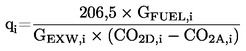
and,
5.2.4. Systems with flow measurement
GEDFW,i = GEXHW,i × qi

5.3. Full flow dilution system
The reported test results of the particulate emission must be determined through the following steps. All calculations must be based upon the average values of the individual modes during the sampling period.
GEDFW,i = GTOTW,i
5.4. Calculation of the particulate mass flow rate
The particulate mass flow rate must be calculated as follows:

where:


i = 1,…n
determined over the test cycle by summation of the average values of the individual modes during the sampling period.
The particulate mass flow rate may be background corrected as follows:

If more than one measurement is made, (Md/MDIL) must be replaced with the average value of (Md/MDIL).
DFi = 13,4 / (conc CO2 + (conc CO + conc HC) × 10–4)) for the individual modes
or,
DFi = 13,4 / concCO2 for the individual modes
5.5. Calculation of the specific emission
The particulate emission must be calculated in the following way:

5.6. Effective weighting factor
The effective weighting factor WFE,i for each mode must be calculated in the following way:

The value of the effective weighting factors must be within ± 0,003 (0,005 for the idle mode) of the weighting factors listed in paragraph 2.7.1.
6. CALCULATION OF THE SMOKE VALUES
6.1. Bessel algorithm
The Bessel algorithm must be used to compute the 1 s average values from the instantaneous smoke readings, converted in accordance with paragraph 6.3.1. The algorithm emulates a low pass second order filter, and its use requires iterative calculations to determine the coefficients. These coefficients are a function of the response time of the opacimeter system and the sampling rate. Therefore, paragraph 6.1.1. must be repeated whenever the system response time and/or sampling rate changes.
6.1.1. Calculation of filter response time and Bessel constants
The required Bessel response time (tf) is a function of the physical and electrical response times of the opacimeter system, as specified in annex 4, appendix 4, paragraph 5.2.4., and must be calculated by the following equation:

where:
|
tp |
= |
physical response time, s |
|
te |
= |
electrical response time, s |
The calculations for estimating the filter cut-off frequency (fc) are based on a step input of 0 to 1 in ≤ 0.01s (see annex 8). The response time is defined as the time between when the Bessel output reaches 10 per cent (t10) and when it reaches 90 per cent (t90) of this step function. This must be obtained by iterating on fc until t90 – t10 ≈ tf. The first iteration for fc is given by the following formula:
fc = π / (10 × tf)
The Bessel constants E and K must be calculated by the following equations:

K = 2 × E × (D × Ω2 – 1) – 1
where:
|
D |
= |
0,618034 |
|
Δt |
= |
1 / sampling rate |
|
Ω |
= |
1 / [tan(π × Δt × fc)] |
6.1.2. Calculation of the Bessel Algorithm
Using the values of E and K, the 1 s Bessel averaged response to a step input Si must be calculated as follows:
|
Yi |
= |
Yi–1 + E × (Si + 2 × Si–1 + Si–2 – 4 × Yi–2) + K × (Yi–1 – Yi–2) |
where:
Si–2 = Si–1 = 0
Si = 1
Yi–2 = Yi–1 = 0
The times t10 and t90 must be interpolated. The difference in time between t90 and t10 defines the response time tf for that value of fc. If this response time is not close enough to the required response time, iteration must be continued until the actual response time is within 1 per cent of the required response as follows:

6.2. Data evaluation
The smoke measurement values must be sampled with a minimum rate of 20 Hz.
6.3. Determination of smoke
6.3.1. Data conversion
Since the basic measurement unit of all opacimeters is transmittance, the smoke values must be converted from transmittance (τ) to the light absorption coefficient (k) as follows:

and: N = 100 – τ
where:
|
k |
= |
light absorption coefficient, m–1 |
|
LA |
= |
effective optical path length, as submitted by instrument manufacturer, m |
|
N |
= |
opacity, % |
|
τ |
= |
transmittance, % |
The conversion must be applied, before any further data processing is made.
6.3.2. Calculation of Bessel averaged smoke
The proper cut-off frequency fc is the one that produces the required filter response time tf. Once this frequency has been determined through the iterative process of paragraph 6.1.1., the proper Bessel algorithm constants E and K must be calculated. The Bessel algorithm must then be applied to the instantaneous smoke trace (k-value), as described in paragraph 6.1.2:
|
Yi |
= |
Yi–1 + E × (Si + 2 × Si–1 + Si–2 – 4 × Yi–2) + K × (Yi–1 – Yi–2) |
The Bessel algorithm is recursive in nature. Thus, it needs some initial input values of Si–1 and Si–2 and initial output values Yi–1 and Yi–2 to get the algorithm started. These may be assumed to be 0.
For each load step of the three speeds A, B and C, the maximum 1s value Ymax must be selected from the individual Yi values of each smoke trace.
6.3.3. Final result
The mean smoke values (SV) from each cycle (test speed) must be calculated as follows:
|
For test speed A: |
= |
SVA |
= |
(Ymax1,A + Ymax2,A + Ymax3,A) / 3 |
|
For test speed B: |
= |
SVB |
= |
(Ymax1,B + Ymax2,B + Ymax3,B) / 3 |
|
For test speed C: |
= |
SVC |
= |
(Ymax1,C + Ymax2,C + Ymax3,C) / 3 |
where:
|
Ymax1, Ymax2, Ymax3 |
= |
highest 1 s Bessel averaged smoke value at each of the three load steps |
The final value must be calculated as follows:
|
SV |
= |
(0,43 × SVA) + (0,56 × SVB) + (0,01 × SVC) |
ANNEX 4
Appendix 2
ETC TEST CYCLE
1. ENGINE MAPPING PROCEDURE
1.1. Determination of the mapping speed range
For generating the ETC on the test cell, the engine needs to be mapped prior to the test cycle for determining the speed vs. torque curve. The minimum and maximum mapping speeds are defined as follows:
|
Minimum mapping speed |
= |
idle speed |
|
Maximum mapping speed |
= |
nhi × 1,02 or speed where full load torque drops off to zero, whichever is lower |
1.2. Performing the engine power map
The engine must be warmed up at maximum power in order to stabilise the engine parameters according to the recommendation of the manufacturer and good engineering practice. When the engine is stabilised, the engine map must be performed as follows:
The engine must be unloaded and operated at idle speed.
The engine must be operated at full load setting of the injection pump at minimum mapping speed.
The engine speed must be increased at an average rate of 8 ± 1 min–1/s from minimum to maximum mapping speed. Engine speed and torque points must be recorded at a sample rate of a least one point per second.
1.3. Mapping curve generation
All data points recorded under paragraph 1.2. must be connected using linear interpolation between points. The resulting torque curve is the mapping curve and must be used to convert the normalised torque values of the engine cycle into actual torque values for the test cycle, as described in paragraph 2.
1.4. Alternate mapping
If a manufacturer believes that the above mapping techniques are unsafe or unrepresentative for any given engine, alternate mapping techniques may be used. These alternate techniques must satisfy the intent of the specified mapping procedures to determine the maximum available torque at all engine speeds achieved during the test cycles. Deviations from the mapping techniques specified in this paragraph for reasons of safety or representativeness must be approved by the Technical Service along with the justification for their use. In no case, however, must descending continual sweeps of engine speed be used for governed or turbocharged engines.
1.5. Replicate tests
An engine need not be mapped before each and every test cycle. An engine must be remapped prior to a test cycle if:
|
— |
an unreasonable amount of time has transpired since the last map, as determined by engineering judgement, or, |
|
— |
physical changes or recalibrations have been made to the engine, which may potentially affect engine performance. |
2. GENERATION OF THE REFERENCE TEST CYCLE
The transient test cycle is described in appendix 3 to this annex. The normalised values for torque and speed must be changed to the actual values, as follows, resulting in the reference cycle.
2.1. Actual speed
The speed must be unnormalised using the following equation:

The reference speed (nref) corresponds to the 100 per cent speed values specified in the engine dynamometer schedule of appendix 3. It is defined as follows (see Figure 1 of the Regulation):
nref = nlo + 95 % × (nhi – nlo)
where nhi and nlo are either specified according to the Regulation, paragraph 2 or determined according to annex 4, appendix 1, paragraph 1.1.
2.2. Actual torque
The torque is normalised to the maximum torque at the respective speed. The torque values of the reference cycle must be unnormalised, using the mapping curve determined according to section 1.3, as follows:

for the respective actual speed as determined in paragraph 2.1.
The negative torque values of the motoring points (‘m’) must take on, for purposes of reference cycle generation, unnormalised values determined in either of the following ways:
|
— |
negative 40 per cent of the positive torque available at the associated speed point; |
|
— |
mapping of the negative torque required to motor the engine from minimum to maximum mapping speed; |
|
— |
determination of the negative torque required to motor the engine at idle and reference speeds and linear interpolation between these two points. |
2.3. Example of the unnormalisation procedure
As an example, the following test point must be unnormalised:
|
% speed |
= |
43 |
|
% torque |
= |
82 |
Given the following values:
|
reference speed |
= |
2 200 min–1 |
|
idle speed |
= |
600 min–1 |
results in,
|
actual speed |
= |
|
|
actual torque |
= |
|
where the maximum torque observed from the mapping curve at 1 288 min–1 is 700 Nm.
3. EMISSIONS TEST RUN
At the manufacturers request, a dummy test may be run for conditioning of the engine and exhaust system before the measurement cycle.
NG and LPG fuelled engines must be run-in using the ETC test. The engine must be run over a minimum of two ETC cycles and until the CO emission measured over one ETC cycle does not exceed by more than 10 per cent the CO emission measured over the previous ETC cycle.
3.1. Preparation of the sampling filters (if applicable)
At least one hour before the test, each filter (pair) must be placed in a closed, but unsealed petri dish and placed in a weighing chamber for stabilisation. At the end of the stabilisation period, each filter (pair) must be weighed and the tare weight must be recorded. The filter (pair) must then be stored in a closed petri dish or sealed filter holder until needed for testing. If the filter (pair) is not used within eight hours of its removal from the weighing chamber, it must be conditioned and reweighed before use.
3.2. Installation of the measuring equipment
The instrumentation and sample probes must be installed as required. The tailpipe must be connected to the full flow dilution system.
3.3. Starting the dilution system and the engine
The dilution system and the engine must be started and warmed up until all temperatures and pressures have stabilised at maximum power according to the recommendation of the manufacturer and good engineering practice.
3.4. Starting the particulate sampling system (if applicable)
The particulate sampling system must be started and running on by-pass. The particulate background level of the dilution air may be determined by passing dilution air through the particulate filters. If filtered dilution air is used, one measurement may be done prior to or after the test. If the dilution air is not filtered, measurements at the beginning and at the end of the cycle, may be done, and the values averaged.
3.5. Adjustment of the full flow dilution system
The total diluted exhaust gas flow must be set to eliminate water condensation in the system, and to obtain a maximum filter face temperature of 325 K (52 °C) or less (see annex 4, appendix 6, paragraph 2.3.1., DT).
3.6. Checking the analysers
The emission analysers must be set at zero and spanned. If sample bags are used, they must be evacuated.
3.7. Engine starting procedure
The stabilised engine must be started according to the manufacturer's recommended starting procedure in the owner's manual, using either a production starter motor or the dynamometer. Optionally, the test may start directly from the engine preconditioning phase without shutting the engine off, when the engine has reached the idle speed.
3.8. Test cycle
3.8.1. Test sequence
The test sequence must be started, if the engine has reached idle speed. The test must be performed according to the reference cycle as set out in paragraph 2 of this appendix. Engine speed and torque command set points must be issued at 5 Hz (10 Hz recommended) or greater. Feedback engine speed and torque must be recorded at least once every second during the test cycle, and the signals may be electronically filtered.
3.8.2. Analyser response
At the start of the engine or test sequence, if the cycle is started directly from the preconditioning, the measuring equipment must be started, simultaneously:
|
— |
start collecting or analysing dilution air; |
|
— |
start collecting or analysing diluted exhaust gas; |
|
— |
start measuring the amount of diluted exhaust gas (CVS) and the required temperatures and pressures; |
|
— |
start recording the feedback data of speed and torque of the dynamometer. |
HC and NOx must be measured continuously in the dilution tunnel with a frequency of 2 Hz. The average concentrations must be determined by integrating the analyser signals over the test cycle. The system response time must be no greater than 20 s, and must be coordinated with CVS flow fluctuations and sampling time/test cycle offsets, if necessary. CO, CO2, NMHC and CH4 must be determined by integration or by analysing the concentrations in the sample bag, collected over the cycle. The concentrations of the gaseous pollutants in the dilution air must be determined by integration or by collecting into the background bag. All other values must be recorded with a minimum of one measurement per second (1 Hz).
3.8.3. Particulate sampling (if applicable)
At the start of the engine or test sequence, if the cycle is started directly from the preconditioning, the particulate sampling system must be switched from by-pass to collecting particulates.
If no flow compensation is used, the sample pump(s) must be adjusted so that the flow rate through the particulate sample probe or transfer tube is maintained at a value within ± 5 per cent of the set flow rate. If flow compensation (i.e., proportional control of sample flow) is used, it must be demonstrated that the ratio of main tunnel flow to particulate sample flow does not change by more than ± 5 per cent of its set value (except for the first 10 seconds of sampling).
Note: For double dilution operation, sample flow is the net difference between the flow rate through the sample filters and the secondary dilution air flow rate.
The average temperature and pressure at the gas meter(s) or flow instrumentation inlet must be recorded. If the set flow rate cannot be maintained over the complete cycle (within ± 5 per cent) because of high particulate loading on the filter, the test must be voided. The test must be rerun using a lower flow rate and/or a larger diameter filter.
3.8.4. Engine stalling
If the engine stalls anywhere during the test cycle, the engine must be preconditioned and restarted, and the test repeated. If a malfunction occurs in any of the required test equipment during the test cycle, the test must be voided.
3.8.5. Operations after test
At the completion of the test, the measurement of the diluted exhaust gas volume, the gas flow into the collecting bags and the particulate sample pump must be stopped. For an integrating analyser system, sampling must continue until system response times have elapsed.
The concentrations of the collecting bags, if used, must be analysed as soon as possible and in any case not later than 20 minutes after the end of the test cycle.
After the emission test, a zero gas and the same span gas must be used for re-checking the analysers. The test will be considered acceptable if the difference between the pre-test and post-test results is less than 2 per cent of the span gas value.
For diesel engines only, the particulate filters must be returned to the weighing chamber no later than one hour after completion of the test and must be conditioned in a closed, but unsealed petri dish for at least one hour, but not more than 80 hours before weighing.
3.9. Verification of the test run
3.9.1. Data shift
To minimise the biasing effect of the time lag between the feedback and reference cycle values, the entire engine speed and torque feedback signal sequence may be advanced or delayed in time with respect to the reference speed and torque sequence. If the feedback signals are shifted, both speed and torque must be shifted the same amount in the same direction.
3.9.2. Calculation of the cycle work
The actual cycle work Wact (kWh) must be calculated using each pair of engine feedback speed and torque values recorded. This must be done after any feedback data shift has occurred, if this option is selected. The actual cycle work Wact is used for comparison to the reference cycle work Wref and for calculating the brake specific emissions (see paragraphs 4.4. and 5.2). The same methodology must be used for integrating both reference and actual engine power. If values are to be determined between adjacent reference or adjacent measured values, linear interpolation must be used.
In integrating the reference and actual cycle work, all negative torque values must be set equal to zero and included. If integration is performed at a frequency of less than 5 Hertz, and if, during a given time segment, the torque value changes from positive to negative or negative to positive, the negative portion must be computed and set equal to zero. The positive portion must be included in the integrated value.
Wact must be between –15 % and +5 % of Wref.
3.9.3. Validation statistics of the test cycle
Linear regressions of the feedback values on the reference values must be performed for speed, torque and power. This must be done after any feedback data shift has occurred, if this option is selected. The method of least squares must be used, with the best fit equation having the form:
y = mx + b
where:
|
y |
= |
feedback (actual) value of speed (min–1), torque (Nm), or power (kW) |
|
m |
= |
slope of the regression line |
|
x |
= |
reference value of speed (min–1), torque (Nm), or power (kW) |
|
b |
= |
y intercept of the regression line |
The standard error of estimate (SE) of y on x and the coefficient of determination (r2) must be calculated for each regression line.
It is recommended that this analysis be performed at 1 Hertz. All negative reference torque values and the associated feedback values must be deleted from the calculation of cycle torque and power validation statistics. For a test to be considered valid, the criteria of table 6 must be met.
Table 6
Regression line tolerances
|
|
Speed |
Torque |
Power |
|
Standard error of estimate (SE) of Y on X |
max 100 min–1 |
max 13 % (15 %) of power map maximum engine torque |
max 8 % (15 %) of power map maximum engine power |
|
Slope of the regression line, m |
0,95 to 1,03 |
0,83 – 1,03 |
0,89 – 1,03 (0,83 – 1,03) |
|
Coefficient of determination, r2 |
min 0,9700 (min 0,9500) |
min 0,8800 (min 0,7500) |
min 0,9100 (min 0,7500) |
|
Y intercept of the regression line, b |
± 50 min–1 |
± 20 Nm or ± 2 % (± 20 Nm or ± 3 %) of max torque whichever is greater |
± 4 kW or ± 2 % (± 4 Kw or ± 3 %) of max power whichever is greater |
The figures shown in brackets may be used for the type-approval testing of gas engines until 1 October 2005.
Table 7
Permitted Point Deletions From Regression Analysis
|
Condition |
Points to be deleted |
|
Full load and torque feedback ≠ torque reference |
Torque and/or power |
|
No load, not an idle point, and torque feedback > torque reference |
Torque and/or power |
|
No load/closed throttle, idle point and speed > reference idle speed |
Speed and/or power |
4. CALCULATION OF THE GASEOUS EMISSIONS
4.1. Determination of the diluted exhaust gas flow
The total diluted exhaust gas flow over the cycle (kg/test) must be calculated from the measurement values over the cycle and the corresponding calibration data of the flow measurement device (V0 for PDP or KV for CFV, as determined in annex 4, appendix 5, paragraph 2.). The following formulae must be applied, if the temperature of the diluted exhaust is kept constant over the cycle by using a heat exchanger (± 6 K for a PDP-CVS, ± 11 K for a CFV-CVS, see annex 4, appendix 6, paragraph 2.3.).
For the PDP-CVS system
|
MTOTW |
= |
1,293 × V0 × NP × (pB – p1) × 273 / (101,3 × T) |
where:
|
MTOTW |
= |
mass of the diluted exhaust gas on wet basis over the cycle, kg |
|
V0 |
= |
volume of gas pumped per revolution under test conditions, m3/rev |
|
NP |
= |
total revolutions of pump per test |
|
pB |
= |
atmospheric pressure in the test cell, kPa |
|
p1 |
= |
pressure depression below atmospheric at pump inlet, kPa |
|
T |
= |
average temperature of the diluted exhaust gas at pump inlet over the cycle, K |
For the CFV-CVS system
MTOTW = 1,293 × t × Kv × pA / T0,5
where:
|
MTOTW |
= |
mass of the diluted exhaust gas on wet basis over the cycle, kg |
|
t |
= |
cycle time, s |
|
KV |
= |
calibration coefficient of the critical flow venturi for standard conditions, |
|
pA |
= |
absolute pressure at venturi inlet, kPa |
|
T |
= |
absolute temperature at venturi inlet, K |
If a system with flow compensation is used (i.e. without heat exchanger), the instantaneous mass emissions must be calculated and integrated over the cycle. In this case, the instantaneous mass of the diluted exhaust gas must be calculated as follows.
For the PDP-CVS system:
MTOTW,i = 1,293 × V0 × NP,i × (pB – p1) × 273 / (101,3 ≅ T)
where:
|
MTOTW,i |
= |
instantaneous mass of the diluted exhaust gas on wet basis, kg |
|
NP,i |
= |
total revolutions of pump per time interval |
For the CFV-CVS system:
|
MTOTW,i |
= |
1,293 × Δti × KV × pA / T0,5 |
where:
|
MTOTW,i |
= |
instantaneous mass of the diluted exhaust gas on wet basis, kg |
|
Δti |
= |
time interval, s |
If the total sample mass of particulates (MSAM) and gaseous pollutants exceeds 0,5 per cent of the total CVS flow (MTOTW), the CVS flow must be corrected for MSAM or the particulate sample flow must be returned to the CVS prior to the flow measuring device (PDP or CFV).
4.2. NOx correction for humidity
As the NOx emission depends on ambient air conditions, the NOx concentration must be corrected for ambient air humidity with the factors given in the following formulae.
|
(a) |
for diesel engines: |
|
(b) |
for gas engines: |
where:
|
Ha |
= |
humidity of the intake air, grams of water per kg of dry air, |
in which:

|
Ra |
= |
relative humidity of the intake air, % |
|
pa |
= |
saturation vapour pressure of the intake air, kPa |
|
pB |
= |
total barometric pressure, kPa |
4.3. Calculation of the emission mass flow
4.3.1. Systems with constant mass flow
For systems with heat exchanger, the mass of the pollutants (g/test) must be determined from the following equations:
|
(1) |
NOx mass |
= |
0,001587 · NOx conc · KH,D · MTOTW |
(diesel engines) |
|
(2) |
NOx mass |
= |
0,001587 · NOx conc · KH,G · MTOTW |
(gas engines) |
|
(3) |
COmass |
= |
0,000966 · COconc · MTOTW |
|
|
(4) |
HCmass |
= |
0,000479 · HCconc · MTOTW′ |
(diesel engines) |
|
(5) |
HCmass |
= |
0,000502 · HCconc · MTOTW′ |
(LPG fuelled engines) |
|
(6) |
HCmass |
= |
0,000552 · HCconc · MTOTW′ |
(NG fuelled engines) |
|
(7) |
NMHCmass |
= |
0,000479 · NMHCconc · MTOTW′ |
(diesel engines) |
|
(8) |
NMHCmass |
= |
0,000502 · NMHCconc · MTOTW′ |
(LPG fuelled engines) |
|
(9) |
NMHCmass |
= |
0,000516 × NMHCconc × MTOTW′ |
(NG fuelled engines) |
|
(10) |
CH4 mass |
= |
0,000552 × CH4 conc × MTOTW |
(NG fuelled engines) |
where:
NOx conc, COconc, HCconc (27), NMHCconc, CH4 conc = average background corrected concentrations over the cycle from integration (mandatory for NOx and HC) or bag measurement, ppm
|
MTOTW |
= |
total mass of diluted exhaust gas over the cycle as determined in paragraph 4.1., kg |
|
KH,D |
= |
humidity correction factor for diesel engines as determined in paragraph 4.2., based on cycle averaged intake air humidity |
|
KH,G |
= |
humidity correction factor for gas engines as determined in paragraph 4.2., based on cycle averaged intake air humidity |
Concentrations measured on a dry basis must be converted to a wet basis in accordance with annex 4, appendix 1, paragraph 4.2.
The determination of NMHCconc and CH4 conc depends on the method used (see annex 4, appendix 4, paragraph 3.3.4.). Both concentrations must be determined as follows, whereby CH4 is subtracted from HC for the determination of NMHCconc:
|
(a) |
GC method NMHCconc = HCconc – CH4 conc CH4 conc = as measured |
|
(b) |
NMC method 

|
where:
|
HC(w/Cutter) |
= |
HC concentration with the sample gas flowing through the NMC |
|
HC(w/o Cutter) |
= |
HC concentration with the sample gas bypassing the NMC |
|
CEM |
= |
methane efficiency as determined per annex 4, appendix 5, paragraph 1.8.4.1. |
|
CEE |
= |
ethane efficiency as determined per annex 4, appendix 5, paragraph 1.8.4.2. |
4.3.1.1. Determination of the background corrected concentrations
The average background concentration of the gaseous pollutants in the dilution air must be subtracted from measured concentrations to get the net concentrations of the pollutants. The average values of the background concentrations can be determined by the sample bag method or by continuous measurement with integration. The following formula must be used.
conc = conce – concd · (1 – (1/DF))
where:
|
conc |
= |
concentration of the respective pollutant in the diluted exhaust gas, corrected by the amount of the respective pollutant contained in the dilution air, ppm |
|
conce |
= |
concentration of the respective pollutant measured in the diluted exhaust gas, ppm |
|
concd |
= |
concentration of the respective pollutant measured in the dilution air, ppm |
|
DF |
= |
dilution factor |
The dilution factor shall be calculated as follows:
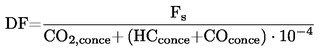
where:
|
CO2,conce |
= |
concentration of CO2 in the diluted exhaust gas, % vol |
|
HCconce |
= |
concentration of HC in the diluted exhaust gas, ppm C1 |
|
COconce |
= |
concentration of CO in the diluted exhaust gas, ppm |
|
FS |
= |
stoichiometric factor |
Concentrations measured on dry basis must be converted to a wet basis in accordance with annex 4, appendix 1, paragraph 4.2.
The stoichiometric factor must be calculated as follows:

where:
|
x, y |
= |
fuel composition CxHy |
Alternatively, if the fuel composition is not known, the following stoichiometric factors may be used:
|
FS (diesel) |
= |
13,4 |
|
FS (LPG) |
= |
11,6 |
|
FS (NG) |
= |
9,5 |
4.3.2. Systems with flow compensation
For systems without heat exchanger, the mass of the pollutants (g/test) must be determined by calculating the instantaneous mass emissions and integrating the instantaneous values over the cycle. Also, the background correction must be applied directly to the instantaneous concentration value. The following formulae must be applied:
|
(1) |
= |
NOx mass |
= |
|
|
(2) |
= |
NOx mass |
= |
|
|
(3) |
= |
COmass |
= |
|
|
(4) |
= |
HCmass |
= |
|
|
(5) |
= |
HCmass |
= |
|
|
(6) |
= |
HCmass |
= |
|
|
(7) |
= |
NMHCmass |
= |
|
|
(8) |
= |
NMHCmass |
= |
|
|
(9) |
= |
NMHCmass |
= |
|
|
(10) |
= |
CH4 mass |
= |
|
where:
|
conce |
= |
concentration of the respective pollutant measured in the diluted exhaust gas, ppm |
|
concd |
= |
concentration of the respective pollutant measured in the dilution air, ppm |
|
MTOTW,i |
= |
instantaneous mass of the diluted exhaust gas (see paragraph 4.1.), kg |
|
MTOTW |
= |
total mass of diluted exhaust gas over the cycle (see paragraph 4.1.), kg |
|
KH,D |
= |
humidity correction factor for diesel engines as determined in paragraph 4.2., based on cycle averaged intake air humidity |
|
KH,G |
= |
humidity correction factor for gas engines as determined in paragraph 4.2., based on cycle averaged intake air humidity |
|
DF |
= |
dilution factor as determined in paragraph 4.3.1.1. |
4.4. Calculation of the specific emissions
The emissions (g/kWh) must be calculated for the individual components, as required according to paragraphs 5.2.1. and 5.2.2. for the respective engine technology, in the following way:
|
|
= |
NOx mass / Wact |
(diesel and gas engines) |
|
|
= |
COmass / Wact |
(diesel and gas engines) |
|
|
= |
HCmass / Wact |
(diesel and gas engines) |
|
|
= |
NMHCmass / Wact |
(diesel and gas engines) |
|
|
= |
CH4 mass / Wact |
(NG fuelled gas engines) |
where:
|
Wact |
= |
actual cycle work as determined in paragraph 3.9.2., kWh. |
5. CALCULATION OF THE PARTICULATE EMISSION (IF APPLICABLE)
5.1. Calculation of the mass flow
The particulate mass (g/test) must be calculated as follows:

where:
|
Mf |
= |
particulate mass sampled over the cycle, mg |
|
MTOTW |
= |
total mass of diluted exhaust gas over the cycle as determined in paragraph 4.1., kg |
|
MSAM |
= |
mass of diluted exhaust gas taken from the dilution tunnel for collecting particulates, kg |
and,
|
Mf |
= |
Mf,p + Mf,b, if weighed separately, mg |
|
Mf,p |
= |
particulate mass collected on the primary filter, mg |
|
Mf,b |
= |
particulate mass collected on the back-up filter, mg |
If a double dilution system is used, the mass of the secondary dilution air must be subtracted from the total mass of the double diluted exhaust gas sampled through the particulate filters.
MSAM = MTOT – MSEC
where:
|
MTOT |
= |
mass of double diluted exhaust gas through particulate filter, kg |
|
MSEC |
= |
mass of secondary dilution air, kg |
If the particulate background level of the dilution air is determined in accordance with paragraph 3.4., the particulate mass may be background corrected. In this case, the particulate mass (g/test) must be calculated as follows:

where:
|
Mf, MSAM, MTOTW |
= |
see above |
|
MDIL |
= |
mass of primary dilution air sampled by background particulate sampler, kg |
|
Md |
= |
mass of the collected background particulates of the primary dilution air, mg |
|
DF |
= |
dilution factor as determined in paragraph 4.3.1.1. |
5.2. Calculation of the specific emission
The particulate emission (g/kWh) must be calculated in the following way:

where:
Wact = actual cycle work as determined in paragraph 3.9.2., kWh.
ANNEX 4
Appendix 3
ETC ENGINE DYNAMOMETER SCHEDULE
|
Time |
Norm. Speed |
Norm. Torque |
|
s |
% |
% |
|
1 |
0 |
0 |
|
2 |
0 |
0 |
|
3 |
0 |
0 |
|
4 |
0 |
0 |
|
5 |
0 |
0 |
|
6 |
0 |
0 |
|
7 |
0 |
0 |
|
8 |
0 |
0 |
|
9 |
0 |
0 |
|
10 |
0 |
0 |
|
11 |
0 |
0 |
|
12 |
0 |
0 |
|
13 |
0 |
0 |
|
14 |
0 |
0 |
|
15 |
0 |
0 |
|
16 |
0,1 |
1,5 |
|
17 |
23,1 |
21,5 |
|
18 |
12,6 |
28,5 |
|
19 |
21,8 |
71 |
|
20 |
19,7 |
76,8 |
|
21 |
54,6 |
80,9 |
|
22 |
71,3 |
4,9 |
|
23 |
55,9 |
18,1 |
|
24 |
72 |
85,4 |
|
25 |
86,7 |
61,8 |
|
26 |
51,7 |
0 |
|
27 |
53,4 |
48,9 |
|
28 |
34,2 |
87,6 |
|
29 |
45,5 |
92,7 |
|
30 |
54,6 |
99,5 |
|
31 |
64,5 |
96,8 |
|
32 |
71,7 |
85,4 |
|
33 |
79,4 |
54,8 |
|
34 |
89,7 |
99,4 |
|
35 |
57,4 |
0 |
|
36 |
59,7 |
30,6 |
|
37 |
90,1 |
‘m’ |
|
38 |
82,9 |
‘m’ |
|
39 |
51,3 |
‘m’ |
|
40 |
28,5 |
‘m’ |
|
41 |
29,3 |
‘m’ |
|
42 |
26,7 |
‘m’ |
|
43 |
20,4 |
‘m’ |
|
44 |
14,1 |
0 |
|
45 |
6,5 |
0 |
|
46 |
0 |
0 |
|
47 |
0 |
0 |
|
48 |
0 |
0 |
|
49 |
0 |
0 |
|
50 |
0 |
0 |
|
51 |
0 |
0 |
|
52 |
0 |
0 |
|
53 |
0 |
0 |
|
54 |
0 |
0 |
|
55 |
0 |
0 |
|
56 |
0 |
0 |
|
57 |
0 |
0 |
|
58 |
0 |
0 |
|
59 |
0 |
0 |
|
60 |
0 |
0 |
|
61 |
0 |
0 |
|
62 |
25,5 |
11,1 |
|
63 |
28,5 |
20,9 |
|
64 |
32 |
73,9 |
|
65 |
4 |
82,3 |
|
66 |
34,5 |
80,4 |
|
67 |
64,1 |
86 |
|
68 |
58 |
0 |
|
69 |
50,3 |
83,4 |
|
70 |
66,4 |
99,1 |
|
71 |
81,4 |
99,6 |
|
72 |
88,7 |
73,4 |
|
73 |
52,5 |
0 |
|
74 |
46,4 |
58,5 |
|
75 |
48,6 |
90,9 |
|
76 |
55,2 |
99,4 |
|
77 |
62,3 |
99 |
|
78 |
68,4 |
91,5 |
|
79 |
74,5 |
73,7 |
|
80 |
38 |
0 |
|
81 |
41,8 |
89,6 |
|
82 |
47,1 |
99,2 |
|
83 |
52,5 |
99,8 |
|
84 |
56,9 |
80,8 |
|
85 |
58,3 |
11,8 |
|
86 |
56,2 |
‘m’ |
|
87 |
52 |
‘m’ |
|
88 |
43,3 |
‘m’ |
|
89 |
36,1 |
‘m’ |
|
90 |
27,6 |
‘m’ |
|
91 |
21,1 |
‘m’ |
|
92 |
8 |
0 |
|
93 |
0 |
0 |
|
94 |
0 |
0 |
|
95 |
0 |
0 |
|
96 |
0 |
0 |
|
97 |
0 |
0 |
|
98 |
0 |
0 |
|
99 |
0 |
0 |
|
100 |
0 |
0 |
|
101 |
0 |
0 |
|
102 |
0 |
0 |
|
103 |
0 |
0 |
|
104 |
0 |
0 |
|
105 |
0 |
0 |
|
106 |
0 |
0 |
|
107 |
0 |
0 |
|
108 |
11,6 |
14,8 |
|
109 |
0 |
0 |
|
110 |
27,2 |
74,8 |
|
111 |
17 |
76,9 |
|
112 |
36 |
78 |
|
113 |
59,7 |
86 |
|
114 |
80,8 |
17,9 |
|
115 |
49,7 |
0 |
|
116 |
65,6 |
86 |
|
117 |
78,6 |
72,2 |
|
118 |
64,9 |
‘m’ |
|
119 |
44,3 |
‘m’ |
|
120 |
51,4 |
83,4 |
|
121 |
58,1 |
97 |
|
122 |
69,3 |
99,3 |
|
123 |
72 |
20,8 |
|
124 |
72,1 |
‘m’ |
|
125 |
65,3 |
‘m’ |
|
126 |
64 |
‘m’ |
|
127 |
59,7 |
‘m’ |
|
128 |
52,8 |
‘m’ |
|
129 |
45,9 |
‘m’ |
|
130 |
38,7 |
‘m’ |
|
131 |
32,4 |
‘m’ |
|
132 |
27 |
‘m’ |
|
133 |
21,7 |
‘m’ |
|
134 |
19,1 |
0,4 |
|
135 |
34,7 |
14 |
|
136 |
16,4 |
48,6 |
|
137 |
0 |
11,2 |
|
138 |
1,2 |
2,1 |
|
139 |
30,1 |
19,3 |
|
140 |
30 |
73,9 |
|
141 |
54,4 |
74,4 |
|
142 |
77,2 |
55,6 |
|
143 |
58,1 |
0 |
|
144 |
45 |
82,1 |
|
145 |
68,7 |
98,1 |
|
146 |
85,7 |
67,2 |
|
147 |
60,2 |
0 |
|
148 |
59,4 |
98 |
|
149 |
72,7 |
99,6 |
|
150 |
79,9 |
45 |
|
151 |
44,3 |
0 |
|
152 |
41,5 |
84,4 |
|
153 |
56,2 |
98,2 |
|
154 |
65,7 |
99,1 |
|
155 |
74,4 |
84,7 |
|
156 |
54,4 |
0 |
|
157 |
47,9 |
89,7 |
|
158 |
54,5 |
99,5 |
|
159 |
62,7 |
96,8 |
|
160 |
62,3 |
0 |
|
161 |
46,2 |
54,2 |
|
162 |
44,3 |
83,2 |
|
163 |
48,2 |
13,3 |
|
164 |
51 |
‘m’ |
|
165 |
50 |
‘m’ |
|
166 |
49,2 |
‘m’ |
|
167 |
49,3 |
‘m’ |
|
168 |
49,9 |
‘m’ |
|
169 |
51,6 |
‘m’ |
|
170 |
49,7 |
‘m’ |
|
171 |
48,5 |
‘m’ |
|
172 |
50,3 |
72,5 |
|
173 |
51,1 |
84,5 |
|
174 |
54,6 |
64,8 |
|
175 |
56,6 |
76,5 |
|
176 |
58 |
‘m’ |
|
177 |
53,6 |
‘m’ |
|
178 |
40,8 |
‘m’ |
|
179 |
32,9 |
‘m’ |
|
180 |
26,3 |
‘m’ |
|
181 |
20,9 |
‘m’ |
|
182 |
10 |
0 |
|
183 |
0 |
0 |
|
184 |
0 |
0 |
|
185 |
0 |
0 |
|
186 |
0 |
0 |
|
187 |
0 |
0 |
|
188 |
0 |
0 |
|
189 |
0 |
0 |
|
190 |
0 |
0 |
|
191 |
0 |
0 |
|
192 |
0 |
0 |
|
193 |
0 |
0 |
|
194 |
0 |
0 |
|
195 |
0 |
0 |
|
196 |
0 |
0 |
|
197 |
0 |
0 |
|
198 |
0 |
0 |
|
199 |
0 |
0 |
|
200 |
0 |
0 |
|
201 |
0 |
0 |
|
202 |
0 |
0 |
|
203 |
0 |
0 |
|
204 |
0 |
0 |
|
205 |
0 |
0 |
|
206 |
0 |
0 |
|
207 |
0 |
0 |
|
208 |
0 |
0 |
|
209 |
0 |
0 |
|
210 |
0 |
0 |
|
211 |
0 |
0 |
|
212 |
0 |
0 |
|
213 |
0 |
0 |
|
214 |
0 |
0 |
|
215 |
0 |
0 |
|
216 |
0 |
0 |
|
217 |
0 |
0 |
|
218 |
0 |
0 |
|
219 |
0 |
0 |
|
220 |
0 |
0 |
|
221 |
0 |
0 |
|
222 |
0 |
0 |
|
223 |
0 |
0 |
|
224 |
0 |
0 |
|
225 |
21,2 |
62,7 |
|
226 |
30,8 |
75,1 |
|
227 |
5,9 |
82,7 |
|
228 |
34,6 |
80,3 |
|
229 |
59,9 |
87 |
|
230 |
84,3 |
86,2 |
|
231 |
68,7 |
‘m’ |
|
232 |
43,6 |
‘m’ |
|
233 |
41,5 |
85,4 |
|
234 |
49,9 |
94,3 |
|
235 |
60,8 |
99 |
|
236 |
70,2 |
99,4 |
|
237 |
81,1 |
92,4 |
|
238 |
49,2 |
0 |
|
239 |
56 |
86,2 |
|
240 |
56,2 |
99,3 |
|
241 |
61,7 |
99 |
|
242 |
69,2 |
99,3 |
|
243 |
74,1 |
99,8 |
|
244 |
72,4 |
8,4 |
|
245 |
71,3 |
0 |
|
246 |
71,2 |
9,1 |
|
247 |
67,1 |
‘m’ |
|
248 |
65,5 |
‘m’ |
|
249 |
64,4 |
‘m’ |
|
250 |
62,9 |
25,6 |
|
251 |
62,2 |
35,6 |
|
252 |
62,9 |
24,4 |
|
253 |
58,8 |
‘m’ |
|
254 |
56,9 |
‘m’ |
|
255 |
54,5 |
‘m’ |
|
256 |
51,7 |
17 |
|
257 |
56,2 |
78,7 |
|
258 |
59,5 |
94,7 |
|
259 |
65,5 |
99,1 |
|
260 |
71,2 |
99,5 |
|
261 |
76,6 |
99,9 |
|
262 |
79 |
0 |
|
263 |
52,9 |
97,5 |
|
264 |
53,1 |
99,7 |
|
265 |
59 |
99,1 |
|
266 |
62,2 |
99 |
|
267 |
65 |
99,1 |
|
268 |
69 |
83,1 |
|
269 |
69,9 |
28,4 |
|
270 |
70,6 |
12,5 |
|
271 |
68,9 |
8,4 |
|
272 |
69,8 |
9,1 |
|
273 |
69,6 |
7 |
|
274 |
65,7 |
‘m’ |
|
275 |
67,1 |
‘m’ |
|
276 |
66,7 |
‘m’ |
|
277 |
65,6 |
‘m’ |
|
278 |
64,5 |
‘m’ |
|
279 |
62,9 |
‘m’ |
|
280 |
59,3 |
‘m’ |
|
281 |
54,1 |
‘m’ |
|
282 |
51,3 |
‘m’ |
|
283 |
47,9 |
‘m’ |
|
284 |
43,6 |
‘m’ |
|
285 |
39,4 |
‘m’ |
|
286 |
34,7 |
‘m’ |
|
287 |
29,8 |
‘m’ |
|
288 |
20,9 |
73,4 |
|
289 |
36,9 |
‘m’ |
|
290 |
35,5 |
‘m’ |
|
291 |
20,9 |
‘m’ |
|
292 |
49,7 |
11,9 |
|
293 |
42,5 |
‘m’ |
|
294 |
32 |
‘m’ |
|
295 |
23,6 |
‘m’ |
|
296 |
19,1 |
0 |
|
297 |
15,7 |
73,5 |
|
298 |
25,1 |
76,8 |
|
299 |
34,5 |
81,4 |
|
300 |
44,1 |
87,4 |
|
301 |
52,8 |
98,6 |
|
302 |
63,6 |
99 |
|
303 |
73,6 |
99,7 |
|
304 |
62,2 |
‘m’ |
|
305 |
29,2 |
‘m’ |
|
306 |
46,4 |
22 |
|
307 |
47,3 |
13,8 |
|
308 |
47,2 |
12,5 |
|
309 |
47,9 |
11,5 |
|
310 |
47,8 |
35,5 |
|
311 |
49,2 |
83,3 |
|
312 |
52,7 |
96,4 |
|
313 |
57,4 |
99,2 |
|
314 |
61,8 |
99 |
|
315 |
66,4 |
60,9 |
|
316 |
65,8 |
‘m’ |
|
317 |
59 |
‘m’ |
|
318 |
50,7 |
‘m’ |
|
319 |
41,8 |
‘m’ |
|
320 |
34,7 |
‘m’ |
|
321 |
28,7 |
‘m’ |
|
322 |
25,2 |
‘m’ |
|
323 |
43 |
24,8 |
|
324 |
38,7 |
0 |
|
325 |
48,1 |
31,9 |
|
326 |
40,3 |
61 |
|
327 |
42,4 |
52,1 |
|
328 |
46,4 |
47,7 |
|
329 |
46,9 |
30,7 |
|
330 |
46,1 |
23,1 |
|
331 |
45,7 |
23,2 |
|
332 |
45,5 |
31,9 |
|
333 |
46,4 |
73,6 |
|
334 |
51,3 |
60,7 |
|
335 |
51,3 |
51,1 |
|
336 |
53,2 |
46,8 |
|
337 |
53,9 |
50 |
|
338 |
53,4 |
52,1 |
|
339 |
53,8 |
45,7 |
|
340 |
50,6 |
22,1 |
|
341 |
47,8 |
26 |
|
342 |
41,6 |
17,8 |
|
343 |
38,7 |
29,8 |
|
344 |
35,9 |
71,6 |
|
345 |
34,6 |
47,3 |
|
346 |
34,8 |
80,3 |
|
347 |
35,9 |
87,2 |
|
348 |
38,8 |
90,8 |
|
349 |
41,5 |
94,7 |
|
350 |
47,1 |
99,2 |
|
351 |
53,1 |
99,7 |
|
352 |
46,4 |
0 |
|
353 |
42,5 |
0,7 |
|
354 |
43,6 |
58,6 |
|
355 |
47,1 |
87,5 |
|
356 |
54,1 |
99,5 |
|
357 |
62,9 |
99 |
|
358 |
72,6 |
99,6 |
|
359 |
82,4 |
99,5 |
|
360 |
88 |
99,4 |
|
361 |
46,4 |
0 |
|
362 |
53,4 |
95,2 |
|
363 |
58,4 |
99,2 |
|
364 |
61,5 |
99 |
|
365 |
64,8 |
99 |
|
366 |
68,1 |
99,2 |
|
367 |
73,4 |
99,7 |
|
368 |
73,3 |
29,8 |
|
369 |
73,5 |
14,6 |
|
370 |
68,3 |
0 |
|
371 |
45,4 |
49,9 |
|
372 |
47,2 |
75,7 |
|
373 |
44,5 |
9 |
|
374 |
47,8 |
10,3 |
|
375 |
46,8 |
15,9 |
|
376 |
46,9 |
12,7 |
|
377 |
46,8 |
8,9 |
|
378 |
46,1 |
6,2 |
|
379 |
46,1 |
‘m’ |
|
380 |
45,5 |
‘m’ |
|
381 |
44,7 |
‘m’ |
|
382 |
43,8 |
‘m’ |
|
383 |
41 |
‘m’ |
|
384 |
41,1 |
6,4 |
|
385 |
38 |
6,3 |
|
386 |
35,9 |
0,3 |
|
387 |
33,5 |
0 |
|
388 |
53,1 |
48,9 |
|
389 |
48,3 |
‘m’ |
|
390 |
49,9 |
‘m’ |
|
391 |
48 |
‘m’ |
|
392 |
45,3 |
‘m’ |
|
393 |
41,6 |
3,1 |
|
394 |
44,3 |
79 |
|
395 |
44,3 |
89,5 |
|
396 |
43,4 |
98,8 |
|
397 |
44,3 |
98,9 |
|
398 |
43 |
98,8 |
|
399 |
42,2 |
98,8 |
|
400 |
42,7 |
98,8 |
|
401 |
45 |
99 |
|
402 |
43,6 |
98,9 |
|
403 |
42,2 |
98,8 |
|
404 |
44,8 |
99 |
|
405 |
43,4 |
98,8 |
|
406 |
45 |
99 |
|
407 |
42,2 |
54,3 |
|
408 |
61,2 |
31,9 |
|
409 |
56,3 |
72,3 |
|
410 |
59,7 |
99,1 |
|
411 |
62,3 |
99 |
|
412 |
67,9 |
99,2 |
|
413 |
69,5 |
99,3 |
|
414 |
73,1 |
99,7 |
|
415 |
77,7 |
99,8 |
|
416 |
79,7 |
99,7 |
|
417 |
82,5 |
99,5 |
|
418 |
85,3 |
99,4 |
|
419 |
86,6 |
99,4 |
|
420 |
89,4 |
99,4 |
|
421 |
62,2 |
0 |
|
422 |
52,7 |
96,4 |
|
423 |
50,2 |
99,8 |
|
424 |
49,3 |
99,6 |
|
425 |
52,2 |
99,8 |
|
426 |
51,3 |
100 |
|
427 |
51,3 |
100 |
|
428 |
51,1 |
100 |
|
429 |
51,1 |
100 |
|
430 |
51,8 |
99,9 |
|
431 |
51,3 |
100 |
|
432 |
51,1 |
100 |
|
433 |
51,3 |
100 |
|
434 |
52,3 |
99,8 |
|
435 |
52,9 |
99,7 |
|
436 |
53,8 |
99,6 |
|
437 |
51,7 |
99,9 |
|
438 |
53,5 |
99,6 |
|
439 |
52 |
99,8 |
|
440 |
51,7 |
99,9 |
|
441 |
53,2 |
99,7 |
|
442 |
54,2 |
99,5 |
|
443 |
55,2 |
99,4 |
|
444 |
53,8 |
99,6 |
|
445 |
53,1 |
99,7 |
|
446 |
55 |
99,4 |
|
447 |
57 |
99,2 |
|
448 |
61,5 |
99 |
|
449 |
59,4 |
5,7 |
|
450 |
59 |
0 |
|
451 |
57,3 |
59,8 |
|
452 |
64,1 |
99 |
|
453 |
70,9 |
90,5 |
|
454 |
58 |
0 |
|
455 |
41,5 |
59,8 |
|
456 |
44,1 |
92,6 |
|
457 |
46,8 |
99,2 |
|
458 |
47,2 |
99,3 |
|
459 |
51 |
100 |
|
460 |
53,2 |
99,7 |
|
461 |
53,1 |
99,7 |
|
462 |
55,9 |
53,1 |
|
463 |
53,9 |
13,9 |
|
464 |
52,5 |
‘m’ |
|
465 |
51,7 |
‘m’ |
|
466 |
51,5 |
52,2 |
|
467 |
52,8 |
80 |
|
468 |
54,9 |
95 |
|
469 |
57,3 |
99,2 |
|
470 |
60,7 |
99,1 |
|
471 |
62,4 |
‘m’ |
|
472 |
60,1 |
‘m’ |
|
473 |
53,2 |
‘m’ |
|
474 |
44 |
‘m’ |
|
475 |
35,2 |
‘m’ |
|
476 |
30,5 |
‘m’ |
|
477 |
26,5 |
‘m’ |
|
478 |
22,5 |
‘m’ |
|
479 |
20,4 |
‘m’ |
|
480 |
19,1 |
‘m’ |
|
481 |
19,1 |
‘m’ |
|
482 |
13,4 |
‘m’ |
|
483 |
6,7 |
‘m’ |
|
484 |
3,2 |
‘m’ |
|
485 |
14,3 |
63,8 |
|
486 |
34,1 |
0 |
|
487 |
23,9 |
75,7 |
|
488 |
31,7 |
79,2 |
|
489 |
32,1 |
19,4 |
|
490 |
35,9 |
5,8 |
|
491 |
36,6 |
0,8 |
|
492 |
38,7 |
‘m’ |
|
493 |
38,4 |
‘m’ |
|
494 |
39,4 |
‘m’ |
|
495 |
39,7 |
‘m’ |
|
496 |
40,5 |
‘m’ |
|
497 |
40,8 |
‘m’ |
|
498 |
39,7 |
‘m’ |
|
499 |
39,2 |
‘m’ |
|
500 |
38,7 |
‘m’ |
|
501 |
32,7 |
‘m’ |
|
502 |
30,1 |
‘m’ |
|
503 |
21,9 |
‘m’ |
|
504 |
12,8 |
0 |
|
505 |
0 |
0 |
|
506 |
0 |
0 |
|
507 |
0 |
0 |
|
508 |
0 |
0 |
|
509 |
0 |
0 |
|
510 |
0 |
0 |
|
511 |
0 |
0 |
|
512 |
0 |
0 |
|
513 |
0 |
0 |
|
514 |
30,5 |
25,6 |
|
515 |
19,7 |
56,9 |
|
516 |
16,3 |
45,1 |
|
517 |
27,2 |
4,6 |
|
518 |
21,7 |
1,3 |
|
519 |
29,7 |
28,6 |
|
520 |
36,6 |
73,7 |
|
521 |
61,3 |
59,5 |
|
522 |
40,8 |
0 |
|
523 |
36,6 |
27,8 |
|
524 |
39,4 |
80,4 |
|
525 |
51,3 |
88,9 |
|
526 |
58,5 |
11,1 |
|
527 |
60,7 |
‘m’ |
|
528 |
54,5 |
‘m’ |
|
529 |
51,3 |
‘m’ |
|
530 |
45,5 |
‘m’ |
|
531 |
40,8 |
‘m’ |
|
532 |
38,9 |
‘m’ |
|
533 |
36,6 |
‘m’ |
|
534 |
36,1 |
72,7 |
|
535 |
44,8 |
78,9 |
|
536 |
51,6 |
91,1 |
|
537 |
59,1 |
99,1 |
|
538 |
66 |
99,1 |
|
539 |
75,1 |
99,9 |
|
540 |
81 |
8 |
|
541 |
39,1 |
0 |
|
542 |
53,8 |
89,7 |
|
543 |
59,7 |
99,1 |
|
544 |
64,8 |
99 |
|
545 |
70,6 |
96,1 |
|
546 |
72,6 |
19,6 |
|
547 |
72 |
6,3 |
|
548 |
68,9 |
0,1 |
|
549 |
67,7 |
‘m’ |
|
550 |
66,8 |
‘m’ |
|
551 |
64,3 |
16,9 |
|
552 |
64,9 |
7 |
|
553 |
63,6 |
12,5 |
|
554 |
63 |
7,7 |
|
555 |
64,4 |
38,2 |
|
556 |
63 |
11,8 |
|
557 |
63,6 |
0 |
|
558 |
63,3 |
5 |
|
559 |
60,1 |
9,1 |
|
560 |
61 |
8,4 |
|
561 |
59,7 |
0,9 |
|
562 |
58,7 |
‘m’ |
|
563 |
56 |
‘m’ |
|
564 |
53,9 |
‘m’ |
|
565 |
52,1 |
‘m’ |
|
566 |
49,9 |
‘m’ |
|
567 |
46,4 |
‘m’ |
|
568 |
43,6 |
‘m’ |
|
569 |
40,8 |
‘m’ |
|
570 |
37,5 |
‘m’ |
|
571 |
27,8 |
‘m’ |
|
572 |
17,1 |
0,6 |
|
573 |
12,2 |
0,9 |
|
574 |
11,5 |
1,1 |
|
575 |
8,7 |
0,5 |
|
576 |
8 |
0,9 |
|
577 |
5,3 |
0,2 |
|
578 |
4 |
0 |
|
579 |
3,9 |
0 |
|
580 |
0 |
0 |
|
581 |
0 |
0 |
|
582 |
0 |
0 |
|
583 |
0 |
0 |
|
584 |
0 |
0 |
|
585 |
0 |
0 |
|
586 |
0 |
0 |
|
587 |
8,7 |
22,8 |
|
588 |
16,2 |
49,4 |
|
589 |
23,6 |
56 |
|
590 |
21,1 |
56,1 |
|
591 |
23,6 |
56 |
|
592 |
46,2 |
68,8 |
|
593 |
68,4 |
61,2 |
|
594 |
58,7 |
‘m’ |
|
595 |
31,6 |
‘m’ |
|
596 |
19,9 |
8,8 |
|
597 |
32,9 |
70,2 |
|
598 |
43 |
79 |
|
599 |
57,4 |
98,9 |
|
600 |
72,1 |
73,8 |
|
601 |
53 |
0 |
|
602 |
48,1 |
86 |
|
603 |
56,2 |
99 |
|
604 |
65,4 |
98,9 |
|
605 |
72,9 |
99,7 |
|
606 |
67,5 |
‘m’ |
|
607 |
39 |
‘m’ |
|
608 |
41,9 |
38,1 |
|
609 |
44,1 |
80,4 |
|
610 |
46,8 |
99,4 |
|
611 |
48,7 |
99,9 |
|
612 |
50,5 |
99,7 |
|
613 |
52,5 |
90,3 |
|
614 |
51 |
1,8 |
|
615 |
50 |
‘m’ |
|
616 |
49,1 |
‘m’ |
|
617 |
47 |
‘m’ |
|
618 |
43,1 |
‘m’ |
|
619 |
39,2 |
‘m’ |
|
620 |
40,6 |
0,5 |
|
621 |
41,8 |
53,4 |
|
622 |
44,4 |
65,1 |
|
623 |
48,1 |
67,8 |
|
624 |
53,8 |
99,2 |
|
625 |
58,6 |
98,9 |
|
626 |
63,6 |
98,8 |
|
627 |
68,5 |
99,2 |
|
628 |
72,2 |
89,4 |
|
629 |
77,1 |
0 |
|
630 |
57,8 |
79,1 |
|
631 |
60,3 |
98,8 |
|
632 |
61,9 |
98,8 |
|
633 |
63,8 |
98,8 |
|
634 |
64,7 |
98,9 |
|
635 |
65,4 |
46,5 |
|
636 |
65,7 |
44,5 |
|
637 |
65,6 |
3,5 |
|
638 |
49,1 |
0 |
|
639 |
50,4 |
73,1 |
|
640 |
50,5 |
‘m’ |
|
641 |
51 |
‘m’ |
|
642 |
49,4 |
‘m’ |
|
643 |
49,2 |
‘m’ |
|
644 |
48,6 |
‘m’ |
|
645 |
47,5 |
‘m’ |
|
646 |
46,5 |
‘m’ |
|
647 |
46 |
11,3 |
|
648 |
45,6 |
42,8 |
|
649 |
47,1 |
83 |
|
650 |
46,2 |
99,3 |
|
651 |
47,9 |
99,7 |
|
652 |
49,5 |
99,9 |
|
653 |
50,6 |
99,7 |
|
654 |
51 |
99,6 |
|
655 |
53 |
99,3 |
|
656 |
54,9 |
99,1 |
|
657 |
55,7 |
99 |
|
658 |
56 |
99 |
|
659 |
56,1 |
9,3 |
|
660 |
55,6 |
‘m’ |
|
661 |
55,4 |
‘m’ |
|
662 |
54,9 |
51,3 |
|
663 |
54,9 |
59,8 |
|
664 |
54 |
39,3 |
|
665 |
53,8 |
‘m’ |
|
666 |
52 |
‘m’ |
|
667 |
50,4 |
‘m’ |
|
668 |
50,6 |
0 |
|
669 |
49,3 |
41,7 |
|
670 |
50 |
73,2 |
|
671 |
50,4 |
99,7 |
|
672 |
51,9 |
99,5 |
|
673 |
53,6 |
99,3 |
|
674 |
54,6 |
99,1 |
|
675 |
56 |
99 |
|
676 |
55,8 |
99 |
|
677 |
58,4 |
98,9 |
|
678 |
59,9 |
98,8 |
|
679 |
60,9 |
98,8 |
|
680 |
63 |
98,8 |
|
681 |
64,3 |
98,9 |
|
682 |
64,8 |
64 |
|
683 |
65,9 |
46,5 |
|
684 |
66,2 |
28,7 |
|
685 |
65,2 |
1,8 |
|
686 |
65 |
6,8 |
|
687 |
63,6 |
53,6 |
|
688 |
62,4 |
82,5 |
|
689 |
61,8 |
98,8 |
|
690 |
59,8 |
98,8 |
|
691 |
59,2 |
98,8 |
|
692 |
59,7 |
98,8 |
|
693 |
61,2 |
98,8 |
|
694 |
62,2 |
49,4 |
|
695 |
62,8 |
37,2 |
|
696 |
63,5 |
46,3 |
|
697 |
64,7 |
72,3 |
|
698 |
64,7 |
72,3 |
|
699 |
65,4 |
77,4 |
|
700 |
66,1 |
69,3 |
|
701 |
64,3 |
‘m’ |
|
702 |
64,3 |
‘m’ |
|
703 |
63 |
‘m’ |
|
704 |
62,2 |
‘m’ |
|
705 |
61,6 |
‘m’ |
|
706 |
62,4 |
‘m’ |
|
707 |
62,2 |
‘m’ |
|
708 |
61 |
‘m’ |
|
709 |
58,7 |
‘m’ |
|
710 |
55,5 |
‘m’ |
|
711 |
51,7 |
‘m’ |
|
712 |
49,2 |
‘m’ |
|
713 |
48,8 |
40,4 |
|
714 |
47,9 |
‘m’ |
|
715 |
46,2 |
‘m’ |
|
716 |
45,6 |
9,8 |
|
717 |
45,6 |
34,5 |
|
718 |
45,5 |
37,1 |
|
719 |
43,8 |
‘m’ |
|
720 |
41,9 |
‘m’ |
|
721 |
41,3 |
‘m’ |
|
722 |
41,4 |
‘m’ |
|
723 |
41,2 |
‘m’ |
|
724 |
41,8 |
‘m’ |
|
725 |
41,8 |
‘m’ |
|
726 |
43,2 |
17,4 |
|
727 |
45 |
29 |
|
728 |
44,2 |
‘m’ |
|
729 |
43,9 |
‘m’ |
|
730 |
38 |
10,7 |
|
731 |
56,8 |
‘m’ |
|
732 |
57,1 |
‘m’ |
|
733 |
52 |
‘m’ |
|
734 |
44,4 |
‘m’ |
|
735 |
40,2 |
‘m’ |
|
736 |
39,2 |
16,5 |
|
737 |
38,9 |
73,2 |
|
738 |
39,9 |
89,8 |
|
739 |
42,3 |
98,6 |
|
740 |
43,7 |
98,8 |
|
741 |
45,5 |
99,1 |
|
742 |
45,6 |
99,2 |
|
743 |
48,1 |
99,7 |
|
744 |
49 |
100 |
|
745 |
49,8 |
99,9 |
|
746 |
49,8 |
99,9 |
|
747 |
51,9 |
99,5 |
|
748 |
52,3 |
99,4 |
|
749 |
53,3 |
99,3 |
|
750 |
52,9 |
99,3 |
|
751 |
54,3 |
99,2 |
|
752 |
55,5 |
99,1 |
|
753 |
56,7 |
99 |
|
754 |
61,7 |
98,8 |
|
755 |
64,3 |
47,4 |
|
756 |
64,7 |
1,8 |
|
757 |
66,2 |
‘m’ |
|
758 |
49,1 |
‘m’ |
|
759 |
52,1 |
46 |
|
760 |
52,6 |
61 |
|
761 |
52,9 |
0 |
|
762 |
52,3 |
20,4 |
|
763 |
54,2 |
56,7 |
|
764 |
55,4 |
59,8 |
|
765 |
56,1 |
49,2 |
|
766 |
56,8 |
33,7 |
|
767 |
57,2 |
96 |
|
768 |
58,6 |
98,9 |
|
769 |
59,5 |
98,8 |
|
770 |
61,2 |
98,8 |
|
771 |
62,1 |
98,8 |
|
772 |
62,7 |
98,8 |
|
773 |
62,8 |
98,8 |
|
774 |
64 |
98,9 |
|
775 |
63,2 |
46,3 |
|
776 |
62,4 |
‘m’ |
|
777 |
60,3 |
‘m’ |
|
778 |
58,7 |
‘m’ |
|
779 |
57,2 |
‘m’ |
|
780 |
56,1 |
‘m’ |
|
781 |
56 |
9,3 |
|
782 |
55,2 |
26,3 |
|
783 |
54,8 |
42,8 |
|
784 |
55,7 |
47,1 |
|
785 |
56,6 |
52,4 |
|
786 |
58 |
50,3 |
|
787 |
58,6 |
20,6 |
|
788 |
58,7 |
‘m’ |
|
789 |
59,3 |
‘m’ |
|
790 |
58,6 |
‘m’ |
|
791 |
60,5 |
9,7 |
|
792 |
59,2 |
9,6 |
|
793 |
59,9 |
9,6 |
|
794 |
59,6 |
9,6 |
|
795 |
59,9 |
6,2 |
|
796 |
59,9 |
9,6 |
|
797 |
60,5 |
13,1 |
|
798 |
60,3 |
20,7 |
|
799 |
59,9 |
31 |
|
800 |
60,5 |
42 |
|
801 |
61,5 |
52,5 |
|
802 |
60,9 |
51,4 |
|
803 |
61,2 |
57,7 |
|
804 |
62,8 |
98,8 |
|
805 |
63,4 |
96,1 |
|
806 |
64,6 |
45,4 |
|
807 |
64,1 |
5 |
|
808 |
63 |
3,2 |
|
809 |
62,7 |
14,9 |
|
810 |
63,5 |
35,8 |
|
811 |
64,1 |
73,3 |
|
812 |
64,3 |
37,4 |
|
813 |
64,1 |
21 |
|
814 |
63,7 |
21 |
|
815 |
62,9 |
18 |
|
816 |
62,4 |
32,7 |
|
817 |
61,7 |
46,2 |
|
818 |
59,8 |
45,1 |
|
819 |
57,4 |
43,9 |
|
820 |
54,8 |
42,8 |
|
821 |
54,3 |
65,2 |
|
822 |
52,9 |
62,1 |
|
823 |
52,4 |
30,6 |
|
824 |
50,4 |
‘m’ |
|
825 |
48,6 |
‘m’ |
|
826 |
47,9 |
‘m’ |
|
827 |
46,8 |
‘m’ |
|
828 |
46,9 |
9,4 |
|
829 |
49,5 |
41,7 |
|
830 |
50,5 |
37,8 |
|
831 |
52,3 |
20,4 |
|
832 |
54,1 |
30,7 |
|
833 |
56,3 |
41,8 |
|
834 |
58,7 |
26,5 |
|
835 |
57,3 |
‘m’ |
|
836 |
59 |
‘m’ |
|
837 |
59,8 |
‘m’ |
|
838 |
60,3 |
‘m’ |
|
839 |
61,2 |
‘m’ |
|
840 |
61,8 |
‘m’ |
|
841 |
62,5 |
‘m’ |
|
842 |
62,4 |
‘m’ |
|
843 |
61,5 |
‘m’ |
|
844 |
63,7 |
‘m’ |
|
845 |
61,9 |
‘m’ |
|
846 |
61,6 |
29,7 |
|
847 |
60,3 |
‘m’ |
|
848 |
59,2 |
‘m’ |
|
849 |
57,3 |
‘m’ |
|
850 |
52,3 |
‘m’ |
|
851 |
49,3 |
‘m’ |
|
852 |
47,3 |
‘m’ |
|
853 |
46,3 |
38,8 |
|
854 |
46,8 |
35,1 |
|
855 |
46,6 |
‘m’ |
|
856 |
44,3 |
‘m’ |
|
857 |
43,1 |
‘m’ |
|
858 |
42,4 |
2,1 |
|
859 |
41,8 |
2,4 |
|
860 |
43,8 |
68,8 |
|
861 |
44,6 |
89,2 |
|
862 |
46 |
99,2 |
|
863 |
46,9 |
99,4 |
|
864 |
47,9 |
99,7 |
|
865 |
50,2 |
99,8 |
|
866 |
51,2 |
99,6 |
|
867 |
52,3 |
99,4 |
|
868 |
53 |
99,3 |
|
869 |
54,2 |
99,2 |
|
870 |
55,5 |
99,1 |
|
871 |
56,7 |
99 |
|
872 |
57,3 |
98,9 |
|
873 |
58 |
98,9 |
|
874 |
60,5 |
31,1 |
|
875 |
60,2 |
‘m’ |
|
876 |
60,3 |
‘m’ |
|
877 |
60,5 |
6,3 |
|
878 |
61,4 |
19,3 |
|
879 |
60,3 |
1,2 |
|
880 |
60,5 |
2,9 |
|
881 |
61,2 |
34,1 |
|
882 |
61,6 |
13,2 |
|
883 |
61,5 |
16,4 |
|
884 |
61,2 |
16,4 |
|
885 |
61,3 |
‘m’ |
|
886 |
63,1 |
‘m’ |
|
887 |
63,2 |
4,8 |
|
888 |
62,3 |
22,3 |
|
889 |
62 |
38,5 |
|
890 |
61,6 |
29,6 |
|
891 |
61,6 |
26,6 |
|
892 |
61,8 |
28,1 |
|
893 |
62 |
29,6 |
|
894 |
62 |
16,3 |
|
895 |
61,1 |
‘m’ |
|
896 |
61,2 |
‘m’ |
|
897 |
60,7 |
19,2 |
|
898 |
60,7 |
32,5 |
|
899 |
60,9 |
17,8 |
|
900 |
60,1 |
19,2 |
|
901 |
59,3 |
38,2 |
|
902 |
59,9 |
45 |
|
903 |
59,4 |
32,4 |
|
904 |
59,2 |
23,5 |
|
905 |
59,5 |
40,8 |
|
906 |
58,3 |
‘m’ |
|
907 |
58,2 |
‘m’ |
|
908 |
57,6 |
‘m’ |
|
909 |
57,1 |
‘m’ |
|
910 |
57 |
0,6 |
|
911 |
57 |
26,3 |
|
912 |
56,5 |
29,2 |
|
913 |
56,3 |
20,5 |
|
914 |
56,1 |
‘m’ |
|
915 |
55,2 |
‘m’ |
|
916 |
54,7 |
17,5 |
|
917 |
55,2 |
29,2 |
|
918 |
55,2 |
29,2 |
|
919 |
55,9 |
16 |
|
920 |
55,9 |
26,3 |
|
921 |
56,1 |
36,5 |
|
922 |
55,8 |
19 |
|
923 |
55,9 |
9,2 |
|
924 |
55,8 |
21,9 |
|
925 |
56,4 |
42,8 |
|
926 |
56,4 |
38 |
|
927 |
56,4 |
11 |
|
928 |
56,4 |
35,1 |
|
929 |
54 |
7,3 |
|
930 |
53,4 |
5,4 |
|
931 |
52,3 |
27,6 |
|
932 |
52,1 |
32 |
|
933 |
52,3 |
33,4 |
|
934 |
52,2 |
34,9 |
|
935 |
52,8 |
60,1 |
|
936 |
53,7 |
69,7 |
|
937 |
54 |
70,7 |
|
938 |
55,1 |
71,7 |
|
939 |
55,2 |
46 |
|
940 |
54,7 |
12,6 |
|
941 |
52,5 |
0 |
|
942 |
51,8 |
24,7 |
|
943 |
51,4 |
43,9 |
|
944 |
50,9 |
71,1 |
|
945 |
51,2 |
76,8 |
|
946 |
50,3 |
87,5 |
|
947 |
50,2 |
99,8 |
|
948 |
50,9 |
100 |
|
949 |
49,9 |
99,7 |
|
950 |
50,9 |
100 |
|
951 |
49,8 |
99,7 |
|
952 |
50,4 |
99,8 |
|
953 |
50,4 |
99,8 |
|
954 |
49,7 |
99,7 |
|
955 |
51 |
100 |
|
956 |
50,3 |
99,8 |
|
957 |
50,2 |
99,8 |
|
958 |
49,9 |
99,7 |
|
959 |
50,9 |
100 |
|
960 |
50 |
99,7 |
|
961 |
50,2 |
99,8 |
|
962 |
50,2 |
99,8 |
|
963 |
49,9 |
99,7 |
|
964 |
50,4 |
99,8 |
|
965 |
50,2 |
99,8 |
|
966 |
50,3 |
99,8 |
|
967 |
49,9 |
99,7 |
|
968 |
51,1 |
100 |
|
969 |
50,6 |
99,9 |
|
970 |
49,9 |
99,7 |
|
971 |
49,6 |
99,6 |
|
972 |
49,4 |
99,6 |
|
973 |
49 |
99,5 |
|
974 |
49,8 |
99,7 |
|
975 |
50,9 |
100 |
|
976 |
50,4 |
99,8 |
|
977 |
49,8 |
99,7 |
|
978 |
49,1 |
99,5 |
|
979 |
50,4 |
99,8 |
|
980 |
49,8 |
99,7 |
|
981 |
49,3 |
99,5 |
|
982 |
49,1 |
99,5 |
|
983 |
49,9 |
99,7 |
|
984 |
49,1 |
99,5 |
|
985 |
50,4 |
99,8 |
|
986 |
50,9 |
100 |
|
987 |
51,4 |
99,9 |
|
988 |
51,5 |
99,9 |
|
989 |
52,2 |
99,7 |
|
990 |
52,8 |
74,1 |
|
991 |
53,3 |
46 |
|
992 |
53,6 |
36,4 |
|
993 |
53,4 |
33,5 |
|
994 |
53,9 |
58,9 |
|
995 |
55,2 |
73,8 |
|
996 |
55,8 |
52,4 |
|
997 |
55,7 |
9,2 |
|
998 |
55,8 |
2,2 |
|
999 |
56,4 |
33,6 |
|
1 000 |
55,4 |
‘m’ |
|
1 001 |
55,2 |
‘m’ |
|
1 002 |
55,8 |
26,3 |
|
1 003 |
55,8 |
23,3 |
|
1 004 |
56,4 |
50,2 |
|
1 005 |
57,6 |
68,3 |
|
1 006 |
58,8 |
90,2 |
|
1 007 |
59,9 |
98,9 |
|
1 008 |
62,3 |
98,8 |
|
1 009 |
63,1 |
74,4 |
|
1 010 |
63,7 |
49,4 |
|
1 011 |
63,3 |
9,8 |
|
1 012 |
48 |
0 |
|
1 013 |
47,9 |
73,5 |
|
1 014 |
49,9 |
99,7 |
|
1 015 |
49,9 |
48,8 |
|
1 016 |
49,6 |
2,3 |
|
1 017 |
49,9 |
‘m’ |
|
1 018 |
49,3 |
‘m’ |
|
1 019 |
49,7 |
47,5 |
|
1 020 |
49,1 |
‘m’ |
|
1 021 |
49,4 |
‘m’ |
|
1 022 |
48,3 |
‘m’ |
|
1 023 |
49,4 |
‘m’ |
|
1 024 |
48,5 |
‘m’ |
|
1 025 |
48,7 |
‘m’ |
|
1 026 |
48,7 |
‘m’ |
|
1 027 |
49,1 |
‘m’ |
|
1 028 |
49 |
‘m’ |
|
1 029 |
49,8 |
‘m’ |
|
1 030 |
48,7 |
‘m’ |
|
1 031 |
48,5 |
‘m’ |
|
1 032 |
49,3 |
31,3 |
|
1 033 |
49,7 |
45,3 |
|
1 034 |
48,3 |
44,5 |
|
1 035 |
49,8 |
61 |
|
1 036 |
49,4 |
64,3 |
|
1 037 |
49,8 |
64,4 |
|
1 038 |
50,5 |
65,6 |
|
1 039 |
50,3 |
64,5 |
|
1 040 |
51,2 |
82,9 |
|
1 041 |
50,5 |
86 |
|
1 042 |
50,6 |
89 |
|
1 043 |
50,4 |
81,4 |
|
1 044 |
49,9 |
49,9 |
|
1 045 |
49,1 |
20,1 |
|
1 046 |
47,9 |
24 |
|
1 047 |
48,1 |
36,2 |
|
1 048 |
47,5 |
34,5 |
|
1 049 |
46,9 |
30,3 |
|
1 050 |
47,7 |
53,5 |
|
1 051 |
46,9 |
61,6 |
|
1 052 |
46,5 |
73,6 |
|
1 053 |
48 |
84,6 |
|
1 054 |
47,2 |
87,7 |
|
1 055 |
48,7 |
80 |
|
1 056 |
48,7 |
50,4 |
|
1 057 |
47,8 |
38,6 |
|
1 058 |
48,8 |
63,1 |
|
1 059 |
47,4 |
5 |
|
1 060 |
47,3 |
47,4 |
|
1 061 |
47,3 |
49,8 |
|
1 062 |
46,9 |
23,9 |
|
1 063 |
46,7 |
44,6 |
|
1 064 |
46,8 |
65,2 |
|
1 065 |
46,9 |
60,4 |
|
1 066 |
46,7 |
61,5 |
|
1 067 |
45,5 |
‘m’ |
|
1 068 |
45,5 |
‘m’ |
|
1 069 |
44,2 |
‘m’ |
|
1 070 |
43 |
‘m’ |
|
1 071 |
42,5 |
‘m’ |
|
1 072 |
41 |
‘m’ |
|
1 073 |
39,9 |
‘m’ |
|
1 074 |
39,9 |
38,2 |
|
1 075 |
40,1 |
48,1 |
|
1 076 |
39,9 |
48 |
|
1 077 |
39,4 |
59,3 |
|
1 078 |
43,8 |
19,8 |
|
1 079 |
52,9 |
0 |
|
1 080 |
52,8 |
88,9 |
|
1 081 |
53,4 |
99,5 |
|
1 082 |
54,7 |
99,3 |
|
1 083 |
56,3 |
99,1 |
|
1 084 |
57,5 |
99 |
|
1 085 |
59 |
98,9 |
|
1 086 |
59,8 |
98,9 |
|
1 087 |
60,1 |
98,9 |
|
1 088 |
61,8 |
48,3 |
|
1 089 |
61,8 |
55,6 |
|
1 090 |
61,7 |
59,8 |
|
1 091 |
62 |
55,6 |
|
1 092 |
62,3 |
29,6 |
|
1 093 |
62 |
19,3 |
|
1 094 |
61,3 |
7,9 |
|
1 095 |
61,1 |
19,2 |
|
1 096 |
61,2 |
43 |
|
1 097 |
61,1 |
59,7 |
|
1 098 |
61,1 |
98,8 |
|
1 099 |
61,3 |
98,8 |
|
1 100 |
61,3 |
26,6 |
|
1 101 |
60,4 |
‘m’ |
|
1 102 |
58,8 |
‘m’ |
|
1 103 |
57,7 |
‘m’ |
|
1 104 |
56 |
‘m’ |
|
1 105 |
54,7 |
‘m’ |
|
1 106 |
53,3 |
‘m’ |
|
1 107 |
52,6 |
23,2 |
|
1 108 |
53,4 |
84,2 |
|
1 109 |
53,9 |
99,4 |
|
1 110 |
54,9 |
99,3 |
|
1 111 |
55,8 |
99,2 |
|
1 112 |
57,1 |
99 |
|
1 113 |
56,5 |
99,1 |
|
1 114 |
58,9 |
98,9 |
|
1 115 |
58,7 |
98,9 |
|
1 116 |
59,8 |
98,9 |
|
1 117 |
61 |
98,8 |
|
1 118 |
60,7 |
19,2 |
|
1 119 |
59,4 |
‘m’ |
|
1 120 |
57,9 |
‘m’ |
|
1 121 |
57,6 |
‘m’ |
|
1 122 |
56,3 |
‘m’ |
|
1 123 |
55 |
‘m’ |
|
1 124 |
53,7 |
‘m’ |
|
1 125 |
52,1 |
‘m’ |
|
1 126 |
51,1 |
‘m’ |
|
1 127 |
49,7 |
25,8 |
|
1 128 |
49,1 |
46,1 |
|
1 129 |
48,7 |
46,9 |
|
1 130 |
48,2 |
46,7 |
|
1 131 |
48 |
70 |
|
1 132 |
48 |
70 |
|
1 133 |
47,2 |
67,6 |
|
1 134 |
47,3 |
67,6 |
|
1 135 |
46,6 |
74,7 |
|
1 136 |
47,4 |
13 |
|
1 137 |
46,3 |
‘m’ |
|
1 138 |
45,4 |
‘m’ |
|
1 139 |
45,5 |
24,8 |
|
1 140 |
44,8 |
73,8 |
|
1 141 |
46,6 |
99 |
|
1 142 |
46,3 |
98,9 |
|
1 143 |
48,5 |
99,4 |
|
1 144 |
49,9 |
99,7 |
|
1 145 |
49,1 |
99,5 |
|
1 146 |
49,1 |
99,5 |
|
1 147 |
51 |
100 |
|
1 148 |
51,5 |
99,9 |
|
1 149 |
50,9 |
100 |
|
1 150 |
51,6 |
99,9 |
|
1 151 |
52,1 |
99,7 |
|
1 152 |
50,9 |
100 |
|
1 153 |
52,2 |
99,7 |
|
1 154 |
51,5 |
98,3 |
|
1 155 |
51,5 |
47,2 |
|
1 156 |
50,8 |
78,4 |
|
1 157 |
50,3 |
83 |
|
1 158 |
50,3 |
31,7 |
|
1 159 |
49,3 |
31,3 |
|
1 160 |
48,8 |
21,5 |
|
1 161 |
47,8 |
59,4 |
|
1 162 |
48,1 |
77,1 |
|
1 163 |
48,4 |
87,6 |
|
1 164 |
49,6 |
87,5 |
|
1 165 |
51 |
81,4 |
|
1 166 |
51,6 |
66,7 |
|
1 167 |
53,3 |
63,2 |
|
1 168 |
55,2 |
62 |
|
1 169 |
55,7 |
43,9 |
|
1 170 |
56,4 |
30,7 |
|
1 171 |
56,8 |
23,4 |
|
1 172 |
57 |
‘m’ |
|
1 173 |
57,6 |
‘m’ |
|
1 174 |
56,9 |
‘m’ |
|
1 175 |
56,4 |
4 |
|
1 176 |
57 |
23,4 |
|
1 177 |
56,4 |
41,7 |
|
1 178 |
57 |
49,2 |
|
1 179 |
57,7 |
56,6 |
|
1 180 |
58,6 |
56,6 |
|
1 181 |
58,9 |
64 |
|
1 182 |
59,4 |
68,2 |
|
1 183 |
58,8 |
71,4 |
|
1 184 |
60,1 |
71,3 |
|
1 185 |
60,6 |
79,1 |
|
1 186 |
60,7 |
83,3 |
|
1 187 |
60,7 |
77,1 |
|
1 188 |
60 |
73,5 |
|
1 189 |
60,2 |
55,5 |
|
1 190 |
59,7 |
54,4 |
|
1 191 |
59,8 |
73,3 |
|
1 192 |
59,8 |
77,9 |
|
1 193 |
59,8 |
73,9 |
|
1 194 |
60 |
76,5 |
|
1 195 |
59,5 |
82,3 |
|
1 196 |
59,9 |
82,8 |
|
1 197 |
59,8 |
65,8 |
|
1 198 |
59 |
48,6 |
|
1 199 |
58,9 |
62,2 |
|
1 200 |
59,1 |
70,4 |
|
1 201 |
58,9 |
62,1 |
|
1 202 |
58,4 |
67,4 |
|
1 203 |
58,7 |
58,9 |
|
1 204 |
58,3 |
57,7 |
|
1 205 |
57,5 |
57,8 |
|
1 206 |
57,2 |
57,6 |
|
1 207 |
57,1 |
42,6 |
|
1 208 |
57 |
70,1 |
|
1 209 |
56,4 |
59,6 |
|
1 210 |
56,7 |
39 |
|
1 211 |
55,9 |
68,1 |
|
1 212 |
56,3 |
79,1 |
|
1 213 |
56,7 |
89,7 |
|
1 214 |
56 |
89,4 |
|
1 215 |
56 |
93,1 |
|
1 216 |
56,4 |
93,1 |
|
1 217 |
56,7 |
94,4 |
|
1 218 |
56,9 |
94,8 |
|
1 219 |
57 |
94,1 |
|
1 220 |
57,7 |
94,3 |
|
1 221 |
57,5 |
93,7 |
|
1 222 |
58,4 |
93,2 |
|
1 223 |
58,7 |
93,2 |
|
1 224 |
58,2 |
93,7 |
|
1 225 |
58,5 |
93,1 |
|
1 226 |
58,8 |
86,2 |
|
1 227 |
59 |
72,9 |
|
1 228 |
58,2 |
59,9 |
|
1 229 |
57,6 |
8,5 |
|
1 230 |
57,1 |
47,6 |
|
1 231 |
57,2 |
74,4 |
|
1 232 |
57 |
79,1 |
|
1 233 |
56,7 |
67,2 |
|
1 234 |
56,8 |
69,1 |
|
1 235 |
56,9 |
71,3 |
|
1 236 |
57 |
77,3 |
|
1 237 |
57,4 |
78,2 |
|
1 238 |
57,3 |
70,6 |
|
1 239 |
57,7 |
64 |
|
1 240 |
57,5 |
55,6 |
|
1 241 |
58,6 |
49,6 |
|
1 242 |
58,2 |
41,1 |
|
1 243 |
58,8 |
40,6 |
|
1 244 |
58,3 |
21,1 |
|
1 245 |
58,7 |
24,9 |
|
1 246 |
59,1 |
24,8 |
|
1 247 |
58,6 |
‘m’ |
|
1 248 |
58,8 |
‘m’ |
|
1 249 |
58,8 |
‘m’ |
|
1 250 |
58,7 |
‘m’ |
|
1 251 |
59,1 |
‘m’ |
|
1 252 |
59,1 |
‘m’ |
|
1 253 |
59,4 |
‘m’ |
|
1 254 |
60,6 |
2,6 |
|
1 255 |
59,6 |
‘m’ |
|
1 256 |
60,1 |
‘m’ |
|
1 257 |
60,6 |
‘m’ |
|
1 258 |
59,6 |
4,1 |
|
1 259 |
60,7 |
7,1 |
|
1 260 |
60,5 |
‘m’ |
|
1 261 |
59,7 |
‘m’ |
|
1 262 |
59,6 |
‘m’ |
|
1 263 |
59,8 |
‘m’ |
|
1 264 |
59,6 |
4,9 |
|
1 265 |
60,1 |
5,9 |
|
1 266 |
59,9 |
6,1 |
|
1 267 |
59,7 |
‘m’ |
|
1 268 |
59,6 |
‘m’ |
|
1 269 |
59,7 |
22 |
|
1 270 |
59,8 |
10,3 |
|
1 271 |
59,9 |
10 |
|
1 272 |
60,6 |
6,2 |
|
1 273 |
60,5 |
7,3 |
|
1 274 |
60,2 |
14,8 |
|
1 275 |
60,6 |
8,2 |
|
1 276 |
60,6 |
5,5 |
|
1 277 |
61 |
14,3 |
|
1 278 |
61 |
12 |
|
1 279 |
61,3 |
34,2 |
|
1 280 |
61,2 |
17,1 |
|
1 281 |
61,5 |
15,7 |
|
1 282 |
61 |
9,5 |
|
1 283 |
61,1 |
9,2 |
|
1 284 |
60,5 |
4,3 |
|
1 285 |
60,2 |
7,8 |
|
1 286 |
60,2 |
5,9 |
|
1 287 |
60,2 |
5,3 |
|
1 288 |
59,9 |
4,6 |
|
1 289 |
59,4 |
21,5 |
|
1 290 |
59,6 |
15,8 |
|
1 291 |
59,3 |
10,1 |
|
1 292 |
58,9 |
9,4 |
|
1 293 |
58,8 |
9 |
|
1 294 |
58,9 |
35,4 |
|
1 295 |
58,9 |
30,7 |
|
1 296 |
58,9 |
25,9 |
|
1 297 |
58,7 |
22,9 |
|
1 298 |
58,7 |
24,4 |
|
1 299 |
59,3 |
61 |
|
1 300 |
60,1 |
56 |
|
1 301 |
60,5 |
50,6 |
|
1 302 |
59,5 |
16,2 |
|
1 303 |
59,7 |
50 |
|
1 304 |
59,7 |
31,4 |
|
1 305 |
60,1 |
43,1 |
|
1 306 |
60,8 |
38,4 |
|
1 307 |
60,9 |
40,2 |
|
1 308 |
61,3 |
49,7 |
|
1 309 |
61,8 |
45,9 |
|
1 310 |
62 |
45,9 |
|
1 311 |
62,2 |
45,8 |
|
1 312 |
62,6 |
46,8 |
|
1 313 |
62,7 |
44,3 |
|
1 314 |
62,9 |
44,4 |
|
1 315 |
63,1 |
43,7 |
|
1 316 |
63,5 |
46,1 |
|
1 317 |
63,6 |
40,7 |
|
1 318 |
64,3 |
49,5 |
|
1 319 |
63,7 |
27 |
|
1 320 |
63,8 |
15 |
|
1 321 |
63,6 |
18,7 |
|
1 322 |
63,4 |
8,4 |
|
1 323 |
63,2 |
8,7 |
|
1 324 |
63,3 |
21,6 |
|
1 325 |
62,9 |
19,7 |
|
1 326 |
63 |
22,1 |
|
1 327 |
63,1 |
20,3 |
|
1 328 |
61,8 |
19,1 |
|
1 329 |
61,6 |
17,1 |
|
1 330 |
61 |
0 |
|
1 331 |
61,2 |
22 |
|
1 332 |
60,8 |
40,3 |
|
1 333 |
61,1 |
34,3 |
|
1 334 |
60,7 |
16,1 |
|
1 335 |
60,6 |
16,6 |
|
1 336 |
60,5 |
18,5 |
|
1 337 |
60,6 |
29,8 |
|
1 338 |
60,9 |
19,5 |
|
1 339 |
60,9 |
22,3 |
|
1 340 |
61,4 |
35,8 |
|
1 341 |
61,3 |
42,9 |
|
1 342 |
61,5 |
31 |
|
1 343 |
61,3 |
19,2 |
|
1 344 |
61 |
9,3 |
|
1 345 |
60,8 |
44,2 |
|
1 346 |
60,9 |
55,3 |
|
1 347 |
61,2 |
56 |
|
1 348 |
60,9 |
60,1 |
|
1 349 |
60,7 |
59,1 |
|
1 350 |
60,9 |
56,8 |
|
1 351 |
60,7 |
58,1 |
|
1 352 |
59,6 |
78,4 |
|
1 353 |
59,6 |
84,6 |
|
1 354 |
59,4 |
66,6 |
|
1 355 |
59,3 |
75,5 |
|
1 356 |
58,9 |
49,6 |
|
1 357 |
59,1 |
75,8 |
|
1 358 |
59 |
77,6 |
|
1 359 |
59 |
67,8 |
|
1 360 |
59 |
56,7 |
|
1 361 |
58,8 |
54,2 |
|
1 362 |
58,9 |
59,6 |
|
1 363 |
58,9 |
60,8 |
|
1 364 |
59,3 |
56,1 |
|
1 365 |
58,9 |
48,5 |
|
1 366 |
59,3 |
42,9 |
|
1 367 |
59,4 |
41,4 |
|
1 368 |
59,6 |
38,9 |
|
1 369 |
59,4 |
32,9 |
|
1 370 |
59,3 |
30,6 |
|
1 371 |
59,4 |
30 |
|
1 372 |
59,4 |
25,3 |
|
1 373 |
58,8 |
18,6 |
|
1 374 |
59,1 |
18 |
|
1 375 |
58,5 |
10,6 |
|
1 376 |
58,8 |
10,5 |
|
1 377 |
58,5 |
8,2 |
|
1 378 |
58,7 |
13,7 |
|
1 379 |
59,1 |
7,8 |
|
1 380 |
59,1 |
6 |
|
1 381 |
59,1 |
6 |
|
1 382 |
59,4 |
13,1 |
|
1 383 |
59,7 |
22,3 |
|
1 384 |
60,7 |
10,5 |
|
1 385 |
59,8 |
9,8 |
|
1 386 |
60,2 |
8,8 |
|
1 387 |
59,9 |
8,7 |
|
1 388 |
61 |
9,1 |
|
1 389 |
60,6 |
28,2 |
|
1 390 |
60,6 |
22 |
|
1 391 |
59,6 |
23,2 |
|
1 392 |
59,6 |
19 |
|
1 393 |
60,6 |
38,4 |
|
1 394 |
59,8 |
41,6 |
|
1 395 |
60 |
47,3 |
|
1 396 |
60,5 |
55,4 |
|
1 397 |
60,9 |
58,7 |
|
1 398 |
61,3 |
37,9 |
|
1 399 |
61,2 |
38,3 |
|
1 400 |
61,4 |
58,7 |
|
1 401 |
61,3 |
51,3 |
|
1 402 |
61,4 |
71,1 |
|
1 403 |
61,1 |
51 |
|
1 404 |
61,5 |
56,6 |
|
1 405 |
61 |
60,6 |
|
1 406 |
61,1 |
75,4 |
|
1 407 |
61,4 |
69,4 |
|
1 408 |
61,6 |
69,9 |
|
1 409 |
61,7 |
59,6 |
|
1 410 |
61,8 |
54,8 |
|
1 411 |
61,6 |
53,6 |
|
1 412 |
61,3 |
53,5 |
|
1 413 |
61,3 |
52,9 |
|
1 414 |
61,2 |
54,1 |
|
1 415 |
61,3 |
53,2 |
|
1 416 |
61,2 |
52,2 |
|
1 417 |
61,2 |
52,3 |
|
1 418 |
61 |
48 |
|
1 419 |
60,9 |
41,5 |
|
1 420 |
61 |
32,2 |
|
1 421 |
60,7 |
22 |
|
1 422 |
60,7 |
23,3 |
|
1 423 |
60,8 |
38,8 |
|
1 424 |
61 |
40,7 |
|
1 425 |
61 |
30,6 |
|
1 426 |
61,3 |
62,6 |
|
1 427 |
61,7 |
55,9 |
|
1 428 |
62,3 |
43,4 |
|
1 429 |
62,3 |
37,4 |
|
1 430 |
62,3 |
35,7 |
|
1 431 |
62,8 |
34,4 |
|
1 432 |
62,8 |
31,5 |
|
1 433 |
62,9 |
31,7 |
|
1 434 |
62,9 |
29,9 |
|
1 435 |
62,8 |
29,4 |
|
1 436 |
62,7 |
28,7 |
|
1 437 |
61,5 |
14,7 |
|
1 438 |
61,9 |
17,2 |
|
1 439 |
61,5 |
6,1 |
|
1 440 |
61 |
9,9 |
|
1 441 |
60,9 |
4,8 |
|
1 442 |
60,6 |
11,1 |
|
1 443 |
60,3 |
6,9 |
|
1 444 |
60,8 |
7 |
|
1 445 |
60,2 |
9,2 |
|
1 446 |
60,5 |
21,7 |
|
1 447 |
60,2 |
22,4 |
|
1 448 |
60,7 |
31,6 |
|
1 449 |
60,9 |
28,9 |
|
1 450 |
59,6 |
21,7 |
|
1 451 |
60,2 |
18 |
|
1 452 |
59,5 |
16,7 |
|
1 453 |
59,8 |
15,7 |
|
1 454 |
59,6 |
15,7 |
|
1 455 |
59,3 |
15,7 |
|
1 456 |
59 |
7,5 |
|
1 457 |
58,8 |
7,1 |
|
1 458 |
58,7 |
16,5 |
|
1 459 |
59,2 |
50,7 |
|
1 460 |
59,7 |
60,2 |
|
1 461 |
60,4 |
44 |
|
1 462 |
60,2 |
35,3 |
|
1 463 |
60,4 |
17,1 |
|
1 464 |
59,9 |
13,5 |
|
1 465 |
59,9 |
12,8 |
|
1 466 |
59,6 |
14,8 |
|
1 467 |
59,4 |
15,9 |
|
1 468 |
59,4 |
22 |
|
1 469 |
60,4 |
38,4 |
|
1 470 |
59,5 |
38,8 |
|
1 471 |
59,3 |
31,9 |
|
1 472 |
60,9 |
40,8 |
|
1 473 |
60,7 |
39 |
|
1 474 |
60,9 |
30,1 |
|
1 475 |
61 |
29,3 |
|
1 476 |
60,6 |
28,4 |
|
1 477 |
60,9 |
36,3 |
|
1 478 |
60,8 |
30,5 |
|
1 479 |
60,7 |
26,7 |
|
1 480 |
60,1 |
4,7 |
|
1 481 |
59,9 |
0 |
|
1 482 |
60,4 |
36,2 |
|
1 483 |
60,7 |
32,5 |
|
1 484 |
59,9 |
3,1 |
|
1 485 |
59,7 |
‘m’ |
|
1 486 |
59,5 |
‘m’ |
|
1 487 |
59,2 |
‘m’ |
|
1 488 |
58,8 |
0,6 |
|
1 489 |
58,7 |
‘m’ |
|
1 490 |
58,7 |
‘m’ |
|
1 491 |
57,9 |
‘m’ |
|
1 492 |
58,2 |
‘m’ |
|
1 493 |
57,6 |
‘m’ |
|
1 494 |
58,3 |
9,5 |
|
1 495 |
57,2 |
6 |
|
1 496 |
57,4 |
27,3 |
|
1 497 |
58,3 |
59,9 |
|
1 498 |
58,3 |
7,3 |
|
1 499 |
58,8 |
21,7 |
|
1 500 |
58,8 |
38,9 |
|
1 501 |
59,4 |
26,2 |
|
1 502 |
59,1 |
25,5 |
|
1 503 |
59,1 |
26 |
|
1 504 |
59 |
39,1 |
|
1 505 |
59,5 |
52,3 |
|
1 506 |
59,4 |
31 |
|
1 507 |
59,4 |
27 |
|
1 508 |
59,4 |
29,8 |
|
1 509 |
59,4 |
23,1 |
|
1 510 |
58,9 |
16 |
|
1 511 |
59 |
31,5 |
|
1 512 |
58,8 |
25,9 |
|
1 513 |
58,9 |
40,2 |
|
1 514 |
58,8 |
28,4 |
|
1 515 |
58,9 |
38,9 |
|
1 516 |
59,1 |
35,3 |
|
1 517 |
58,8 |
30,3 |
|
1 518 |
59 |
19 |
|
1 519 |
58,7 |
3 |
|
1 520 |
57,9 |
0 |
|
1 521 |
58 |
2,4 |
|
1 522 |
57,1 |
‘m’ |
|
1 523 |
56,7 |
‘m’ |
|
1 524 |
56,7 |
5,3 |
|
1 525 |
56,6 |
2,1 |
|
1 526 |
56,8 |
‘m’ |
|
1 527 |
56,3 |
‘m’ |
|
1 528 |
56,3 |
‘m’ |
|
1 529 |
56 |
‘m’ |
|
1 530 |
56,7 |
‘m’ |
|
1 531 |
56,6 |
3,8 |
|
1 532 |
56,9 |
‘m’ |
|
1 533 |
56,9 |
‘m’ |
|
1 534 |
57,4 |
‘m’ |
|
1 535 |
57,4 |
‘m’ |
|
1 536 |
58,3 |
13,9 |
|
1 537 |
58,5 |
‘m’ |
|
1 538 |
59,1 |
‘m’ |
|
1 539 |
59,4 |
‘m’ |
|
1 540 |
59,6 |
‘m’ |
|
1 541 |
59,5 |
‘m’ |
|
1 542 |
59,6 |
0,5 |
|
1 543 |
59,3 |
9,2 |
|
1 544 |
59,4 |
11,2 |
|
1 545 |
59,1 |
26,8 |
|
1 546 |
59 |
11,7 |
|
1 547 |
58,8 |
6,4 |
|
1 548 |
58,7 |
5 |
|
1 549 |
57,5 |
‘m’ |
|
1 550 |
57,4 |
‘m’ |
|
1 551 |
57,1 |
1,1 |
|
1 552 |
57,1 |
0 |
|
1 553 |
57 |
4,5 |
|
1 554 |
57,1 |
3,7 |
|
1 555 |
57,3 |
3,3 |
|
1 556 |
57,3 |
16,8 |
|
1 557 |
58,2 |
29,3 |
|
1 558 |
58,7 |
12,5 |
|
1 559 |
58,3 |
12,2 |
|
1 560 |
58,6 |
12,7 |
|
1 561 |
59 |
13,6 |
|
1 562 |
59,8 |
21,9 |
|
1 563 |
59,3 |
20,9 |
|
1 564 |
59,7 |
19,2 |
|
1 565 |
60,1 |
15,9 |
|
1 566 |
60,7 |
16,7 |
|
1 567 |
60,7 |
18,1 |
|
1 568 |
60,7 |
40,6 |
|
1 569 |
60,7 |
59,7 |
|
1 570 |
61,1 |
66,8 |
|
1 571 |
61,1 |
58,8 |
|
1 572 |
60,8 |
64,7 |
|
1 573 |
60,1 |
63,6 |
|
1 574 |
60,7 |
83,2 |
|
1 575 |
60,4 |
82,2 |
|
1 576 |
60 |
80,5 |
|
1 577 |
59,9 |
78,7 |
|
1 578 |
60,8 |
67,9 |
|
1 579 |
60,4 |
57,7 |
|
1 580 |
60,2 |
60,6 |
|
1 581 |
59,6 |
72,7 |
|
1 582 |
59,9 |
73,6 |
|
1 583 |
59,8 |
74,1 |
|
1 584 |
59,6 |
84,6 |
|
1 585 |
59,4 |
76,1 |
|
1 586 |
60,1 |
76,9 |
|
1 587 |
59,5 |
84,6 |
|
1 588 |
59,8 |
77,5 |
|
1 589 |
60,6 |
67,9 |
|
1 590 |
59,3 |
47,3 |
|
1 591 |
59,3 |
43,1 |
|
1 592 |
59,4 |
38,3 |
|
1 593 |
58,7 |
38,2 |
|
1 594 |
58,8 |
39,2 |
|
1 595 |
59,1 |
67,9 |
|
1 596 |
59,7 |
60,5 |
|
1 597 |
59,5 |
32,9 |
|
1 598 |
59,6 |
20 |
|
1 599 |
59,6 |
34,4 |
|
1 600 |
59,4 |
23,9 |
|
1 601 |
59,6 |
15,7 |
|
1 602 |
59,9 |
41 |
|
1 603 |
60,5 |
26,3 |
|
1 604 |
59,6 |
14 |
|
1 605 |
59,7 |
21,2 |
|
1 606 |
60,9 |
19,6 |
|
1 607 |
60,1 |
34,3 |
|
1 608 |
59,9 |
27 |
|
1 609 |
60,8 |
25,6 |
|
1 610 |
60,6 |
26,3 |
|
1 611 |
60,9 |
26,1 |
|
1 612 |
61,1 |
38 |
|
1 613 |
61,2 |
31,6 |
|
1 614 |
61,4 |
30,6 |
|
1 615 |
61,7 |
29,6 |
|
1 616 |
61,5 |
28,8 |
|
1 617 |
61,7 |
27,8 |
|
1 618 |
62,2 |
20,3 |
|
1 619 |
61,4 |
19,6 |
|
1 620 |
61,8 |
19,7 |
|
1 621 |
61,8 |
18,7 |
|
1 622 |
61,6 |
17,7 |
|
1 623 |
61,7 |
8,7 |
|
1 624 |
61,7 |
1,4 |
|
1 625 |
61,7 |
5,9 |
|
1 626 |
61,2 |
8,1 |
|
1 627 |
61,9 |
45,8 |
|
1 628 |
61,4 |
31,5 |
|
1 629 |
61,7 |
22,3 |
|
1 630 |
62,4 |
21,7 |
|
1 631 |
62,8 |
21,9 |
|
1 632 |
62,2 |
22,2 |
|
1 633 |
62,5 |
31 |
|
1 634 |
62,3 |
31,3 |
|
1 635 |
62,6 |
31,7 |
|
1 636 |
62,3 |
22,8 |
|
1 637 |
62,7 |
12,6 |
|
1 638 |
62,2 |
15,2 |
|
1 639 |
61,9 |
32,6 |
|
1 640 |
62,5 |
23,1 |
|
1 641 |
61,7 |
19,4 |
|
1 642 |
61,7 |
10,8 |
|
1 643 |
61,6 |
10,2 |
|
1 644 |
61,4 |
‘m’ |
|
1 645 |
60,8 |
‘m’ |
|
1 646 |
60,7 |
‘m’ |
|
1 647 |
61 |
12,4 |
|
1 648 |
60,4 |
5,3 |
|
1 649 |
61 |
13,1 |
|
1 650 |
60,7 |
29,6 |
|
1 651 |
60,5 |
28,9 |
|
1 652 |
60,8 |
27,1 |
|
1 653 |
61,2 |
27,3 |
|
1 654 |
60,9 |
20,6 |
|
1 655 |
61,1 |
13,9 |
|
1 656 |
60,7 |
13,4 |
|
1 657 |
61,3 |
26,1 |
|
1 658 |
60,9 |
23,7 |
|
1 659 |
61,4 |
32,1 |
|
1 660 |
61,7 |
33,5 |
|
1 661 |
61,8 |
34,1 |
|
1 662 |
61,7 |
17 |
|
1 663 |
61,7 |
2,5 |
|
1 664 |
61,5 |
5,9 |
|
1 665 |
61,3 |
14,9 |
|
1 666 |
61,5 |
17,2 |
|
1 667 |
61,1 |
‘m’ |
|
1 668 |
61,4 |
‘m’ |
|
1 669 |
61,4 |
8,8 |
|
1 670 |
61,3 |
8,8 |
|
1 671 |
61 |
18 |
|
1 672 |
61,5 |
13 |
|
1 673 |
61 |
3,7 |
|
1 674 |
60,9 |
3,1 |
|
1 675 |
60,9 |
4,7 |
|
1 676 |
60,6 |
4,1 |
|
1 677 |
60,6 |
6,7 |
|
1 678 |
60,6 |
12,8 |
|
1 679 |
60,7 |
11,9 |
|
1 680 |
60,6 |
12,4 |
|
1 681 |
60,1 |
12,4 |
|
1 682 |
60,5 |
12 |
|
1 683 |
60,4 |
11,8 |
|
1 684 |
59,9 |
12,4 |
|
1 685 |
59,6 |
12,4 |
|
1 686 |
59,6 |
9,1 |
|
1 687 |
59,9 |
0 |
|
1 688 |
59,9 |
20,4 |
|
1 689 |
59,8 |
4,4 |
|
1 690 |
59,4 |
3,1 |
|
1 691 |
59,5 |
26,3 |
|
1 692 |
59,6 |
20,1 |
|
1 693 |
59,4 |
35 |
|
1 694 |
60,9 |
22,1 |
|
1 695 |
60,5 |
12,2 |
|
1 696 |
60,1 |
11 |
|
1 697 |
60,1 |
8,2 |
|
1 698 |
60,5 |
6,7 |
|
1 699 |
60 |
5,1 |
|
1 700 |
60 |
5,1 |
|
1 701 |
60 |
9 |
|
1 702 |
60,1 |
5,7 |
|
1 703 |
59,9 |
8,5 |
|
1 704 |
59,4 |
6 |
|
1 705 |
59,5 |
5,5 |
|
1 706 |
59,5 |
14,2 |
|
1 707 |
59,5 |
6,2 |
|
1 708 |
59,4 |
10,3 |
|
1 709 |
59,6 |
13,8 |
|
1 710 |
59,5 |
13,9 |
|
1 711 |
60,1 |
18,9 |
|
1 712 |
59,4 |
13,1 |
|
1 713 |
59,8 |
5,4 |
|
1 714 |
59,9 |
2,9 |
|
1 715 |
60,1 |
7,1 |
|
1 716 |
59,6 |
12 |
|
1 717 |
59,6 |
4,9 |
|
1 718 |
59,4 |
22,7 |
|
1 719 |
59,6 |
22 |
|
1 720 |
60,1 |
17,4 |
|
1 721 |
60,2 |
16,6 |
|
1 722 |
59,4 |
28,6 |
|
1 723 |
60,3 |
22,4 |
|
1 724 |
59,9 |
20 |
|
1 725 |
60,2 |
18,6 |
|
1 726 |
60,3 |
11,9 |
|
1 727 |
60,4 |
11,6 |
|
1 728 |
60,6 |
10,6 |
|
1 729 |
60,8 |
16 |
|
1 730 |
60,9 |
17 |
|
1 731 |
60,9 |
16,1 |
|
1 732 |
60,7 |
11,4 |
|
1 733 |
60,9 |
11,3 |
|
1 734 |
61,1 |
11,2 |
|
1 735 |
61,1 |
25,6 |
|
1 736 |
61 |
14,6 |
|
1 737 |
61 |
10,4 |
|
1 738 |
60,6 |
‘m’ |
|
1 739 |
60,9 |
‘m’ |
|
1 740 |
60,8 |
4,8 |
|
1 741 |
59,9 |
‘m’ |
|
1 742 |
59,8 |
‘m’ |
|
1 743 |
59,1 |
‘m’ |
|
1 744 |
58,8 |
‘m’ |
|
1 745 |
58,8 |
‘m’ |
|
1 746 |
58,2 |
‘m’ |
|
1 747 |
58,5 |
14,3 |
|
1 748 |
57,5 |
4,4 |
|
1 749 |
57,9 |
0 |
|
1 750 |
57,8 |
20,9 |
|
1 751 |
58,3 |
9,2 |
|
1 752 |
57,8 |
8,2 |
|
1 753 |
57,5 |
15,3 |
|
1 754 |
58,4 |
38 |
|
1 755 |
58,1 |
15,4 |
|
1 756 |
58,8 |
11,8 |
|
1 757 |
58,3 |
8,1 |
|
1 758 |
58,3 |
5,5 |
|
1 759 |
59 |
4,1 |
|
1 760 |
58,2 |
4,9 |
|
1 761 |
57,9 |
10,1 |
|
1 762 |
58,5 |
7,5 |
|
1 763 |
57,4 |
7 |
|
1 764 |
58,2 |
6,7 |
|
1 765 |
58,2 |
6,6 |
|
1 766 |
57,3 |
17,3 |
|
1 767 |
58 |
11,4 |
|
1 768 |
57,5 |
47,4 |
|
1 769 |
57,4 |
28,8 |
|
1 770 |
58,8 |
24,3 |
|
1 771 |
57,7 |
25,5 |
|
1 772 |
58,4 |
35,5 |
|
1 773 |
58,4 |
29,3 |
|
1 774 |
59 |
33,8 |
|
1 775 |
59 |
18,7 |
|
1 776 |
58,8 |
9,8 |
|
1 777 |
58,8 |
23,9 |
|
1 778 |
59,1 |
48,2 |
|
1 779 |
59,4 |
37,2 |
|
1 780 |
59,6 |
29,1 |
|
1 781 |
50 |
25 |
|
1 782 |
40 |
20 |
|
1 783 |
30 |
15 |
|
1 784 |
20 |
10 |
|
1 785 |
10 |
5 |
|
1 786 |
0 |
0 |
|
1 787 |
0 |
0 |
|
1 788 |
0 |
0 |
|
1 789 |
0 |
0 |
|
1 790 |
0 |
0 |
|
1 791 |
0 |
0 |
|
1 792 |
0 |
0 |
|
1 793 |
0 |
0 |
|
1 794 |
0 |
0 |
|
1 795 |
0 |
0 |
|
1 796 |
0 |
0 |
|
1 797 |
0 |
0 |
|
1 798 |
0 |
0 |
|
1 799 |
0 |
0 |
|
1 800 |
0 |
0 |
|
‘m’ = motoring. |
||
A graphical display of the ETC dynamometer schedule is shown in Figure 5.

ANNEX 4
Appendix 4
MEASUREMENT AND SAMPLING PROCEDURES
1. INTRODUCTION
Gaseous components, particulates, and smoke emitted by the engine submitted for testing must be measured by the methods described in annex 4, appendix 6. The respective paragraphs of annex 4, appendix 6 describe the recommended analytical systems for the gaseous emissions (paragraph 1.), the recommended particulate dilution and sampling systems (paragraph 2.), and the recommended opacimeters for smoke measurement (paragraph 3.).
For the ESC, the gaseous components must be determined in the raw exhaust gas. Optionally, they may be determined in the diluted exhaust gas, if a full flow dilution system is used for particulate determination. Particulates must be determined with either a partial flow or a full flow dilution system.
For the ETC, only a full flow dilution system must be used for determining gaseous and particulate emissions, and is considered the reference system. However, partial flow dilution systems may be approved by the Technical Service, if their equivalency according to paragraph 6.2. to the Regulation is proven, and if a detailed description of the data evaluation and calculation procedures is submitted to the Technical Service.
2. DYNAMOMETER AND TEST CELL EQUIPMENT
The following equipment must be used for emission tests of engines on engine dynamometers.
2.1. Engine dynamometer
An engine dynamometer must be used with adequate characteristics to perform the test cycles described in appendices 1 and 2 to this annex. The speed measuring system must have an accuracy of ± 2 per cent of reading. The torque measuring system must have an accuracy of ± 3 per cent of reading in the range > 20 per cent of full scale, and an accuracy of ± 0,6 per cent of full scale in the range ≤ 20 per cent of full scale.
2.2. Other instruments
Measuring instruments for fuel consumption, air consumption, temperature of coolant and lubricant, exhaust gas pressure and intake manifold depression, exhaust gas temperature, air intake temperature, atmospheric pressure, humidity and fuel temperature must be used, as required. These instruments must satisfy the requirements given in table 8:
Table 8
Accuracy of measuring instruments
|
Measuring instrument |
Accuracy |
|
Fuel Consumption |
± 2 % of Engine's Maximum Value |
|
Air Consumption |
± 2 % of Engine's Maximum Value |
|
Temperatures ≤ 600 K (327 °C) |
± 2 K Absolute |
|
Temperatures ≥ 600 K (327 °C) |
± 1 % of Reading |
|
Atmospheric Pressure |
± 0,1 kPa Absolute |
|
Exhaust Gas Pressure |
± 0,2 kPa Absolute |
|
Intake Depression |
± 0,05 kPa Absolute |
|
Other Pressures |
± 0,1 kPa Absolute |
|
Relative Humidity |
± 3 % Absolute |
|
Absolute Humidity |
± 5 % of Reading |
2.3. Exhaust gas flow
For calculation of the emissions in the raw exhaust, it is necessary to know the exhaust gas flow (see paragraph 4.4. of appendix 1). For the determination of the exhaust flow either of the following methods may be used:
Direct measurement of the exhaust flow by flow nozzle or equivalent metering system;
Measurement of the air flow and the fuel flow by suitable metering systems and calculation of the exhaust flow by the following equation:
|
GEXHW = GAIRW + GFUEL |
(for wet exhaust mass) |
The accuracy of exhaust flow determination must be ± 2,5 per cent of reading or better.
2.4. Diluted exhaust gas flow
For calculation of the emissions in the diluted exhaust using a full flow dilution system (mandatory for the ETC), it is necessary to know the diluted exhaust gas flow (see paragraph 4.3. of appendix 2). The total mass flow rate of the diluted exhaust (GTOTW) or the total mass of the diluted exhaust gas over the cycle (MTOTW) must be measured with a PDP or CFV (annex 4, appendix 6, paragraph 2.3.1.). The accuracy must be ± 2 per cent of reading or better, and must be determined according to the provisions of annex 4, appendix 5, paragraph 2.4.
3. DETERMINATION OF THE GASEOUS COMPONENTS
3.1. General analyser specifications
The analysers must have a measuring range appropriate for the accuracy required to measure the concentrations of the exhaust gas components (paragraph 3.1.1). It is recommended that the analysers be operated such that the measured concentration falls between 15 per cent and 100 per cent of full scale.
If read-out systems (computers, data loggers) can provide sufficient accuracy and resolution below 15 per cent of full scale, measurements below 15 per cent of full scale are also acceptable. In this case, additional calibrations of at least 4 non-zero nominally equally spaced points are to be made to ensure the accuracy of the calibration curves according to annex 4, appendix 5, paragraph 1.5.5.2.
The electromagnetic compatibility (EMC) of the equipment must be on a level as to minimise additional errors.
3.1.1. Measurement error
The total measurement error, including the cross sensitivity to other gases (see annex 4, appendix 5, paragraph 1.9.), must not exceed ± 5 per cent of the reading or ± 3,5 per cent of full scale, whichever is smaller. For concentrations of less than 100 ppm the measurement error must not exceed ± 4 ppm.
3.1.2. Repeatability
The repeatability, defined as 2.5 times the standard deviation of 10 repetitive responses to a given calibration or span gas, has to be not greater than ± 1 per cent of full scale concentration for each range used above 155 ppm (or ppm C) or ± 2 per cent of each range used below 155 ppm (or ppm C).
3.1.3. Noise
The analyser peak-to-peak response to zero and calibration or span gases over any 10 seconds period must not exceed 2 per cent of full scale on all ranges used.
3.1.4. Zero drift
The zero drift during a one hour period must be less than 2 per cent of full scale on the lowest range used. The zero response is defined as the mean response, including noise, to a zero gas during a 30 seconds time interval.
3.1.5. Span drift
The span drift during a one hour period must be less than 2 per cent of full scale on the lowest range used. Span is defined as the difference between the span response and the zero response. The span response is defined as the mean response, including noise, to a span gas during a 30 seconds time interval.
3.2. Gas drying
The optional gas drying device must have a minimal effect on the concentration of the measured gases. Chemical dryers are not an acceptable method of removing water from the sample.
3.3. Analysers
Paragraphs 3.3.1. to 3.3.4. describe the measurement principles to be used. A detailed description of the measurement systems is given in annex 4, appendix 6. The gases to be measured must be analysed with the following instruments. For non-linear analysers, the use of linearising circuits is permitted.
3.3.1. Carbon monoxide (CO) analysis
The carbon monoxide analyser must be of the Non-Dispersive Infra-Red (NDIR) absorption type.
3.3.2. Carbon dioxide (CO2) analysis
The carbon dioxide analyser must be of the Non-Dispersive Infra-Red (NDIR) absorption type.
3.3.3. Hydrocarbon (HC) analysis
For diesel and LPG fuelled gas engines, the hydrocarbon analyser must be of the Heated Flame Ionisation Detector (HFID) type with detector, valves, pipework, etc. heated so as to maintain a gas temperature of 463 K ± 10 K (190 ± 10 °C). For NG fuelled gas engines, the hydrocarbon analyser may be of the non heated Flame Ionisation Detector (FID) type depending upon the method used (see annex 4, appendix 6, paragraph 1.3.).
3.3.4. Non-methane hydrocarbon (NMHC) analysis (NG fuelled gas engines only)
Non-methane hydrocarbons must be determined by either of the following methods:
3.3.4.1. Gas chromatographic (GC) method
Non-methane hydrocarbons must be determined by subtraction of the methane analysed with a Gas Chromatograph (GC) conditioned at 423 K (150 °C) from the hydrocarbons measured according to paragraph 3.3.3.
3.3.4.2. Non-methane cutter (NMC) method
The determination of the non-methane fraction must be performed with a heated NMC operated in line with an FID as per paragraph 3.3.3. by subtraction of the methane from the hydrocarbons.
3.3.5. Oxides of nitrogen (NOx) analysis
The oxides of nitrogen analyser must be of the Chemi-Luminescent Detector (CLD) or Heated Chemi-Luminescent Detector (HCLD) type with a NO2/NO converter, if measured on a dry basis. If measured on a wet basis, a HCLD with converter maintained above 328 K (55 °C) must be used, provided the water quench check (see annex 4, appendix 5, paragraph 1.9.2.2.) is satisfied.
3.4. Sampling of gaseous emissions
3.4.1. Raw exhaust gas (ESC only)
The gaseous emissions sampling probes must be fitted at least 0,5 m or 3 times the diameter of the exhaust pipe — whichever is the larger — upstream of the exit of the exhaust gas system as far as applicable and sufficiently close to the engine as to ensure an exhaust gas temperature of at least 343 K (70 °C) at the probe.
In the case of a multi-cylinder engine with a branched exhaust manifold, the inlet of the probe must be located sufficiently far downstream so as to ensure that the sample is representative of the average exhaust emissions from all cylinders. In multi-cylinder engines having distinct groups of manifolds, such as in a ‘V-engine’ configuration, it is permissible to acquire a sample from each group individually and calculate an average exhaust emission. Other methods which have been shown to correlate with the above methods may be used. For exhaust emission calculation the total exhaust mass flow must be used.
If the engine is equipped with an exhaust after-treatment system, the exhaust sample must be taken downstream of the exhaust after-treatment system.
3.4.2. Diluted exhaust gas (mandatory for ETC, optional for ESC)
The exhaust pipe between the engine and the full flow dilution system must conform to the requirements of annex 4, appendix 6, paragraph 2.3.1., EP.
The gaseous emissions sample probe(s) must be installed in the dilution tunnel at a point where the dilution air and exhaust gas are well mixed, and in close proximity to the particulates sampling probe.
For the ETC, sampling can generally be done in two ways:
|
— |
the pollutants are sampled into a sampling bag over the cycle and measured after completion of the test; |
|
— |
the pollutants are sampled continuously and integrated over the cycle; this method is mandatory for HC and NOx. |
4. DETERMINATION OF THE PARTICULATES
The determination of the particulates requires a dilution system. Dilution may be accomplished by a partial flow dilution system (ESC only) or a full flow dilution system (mandatory for ETC). The flow capacity of the dilution system must be large enough to completely eliminate water condensation in the dilution and sampling systems, and maintain the temperature of the diluted exhaust gas at or below 325 K (52 °C) immediately upstream of the filter holders. Dehumidifying the dilution air before entering the dilution system is permitted, and especially useful if dilution air humidity is high. The temperature of the dilution air must be 298 K ± 5 K (25 °C ± 5 °C). If the ambient temperature is below 293 K (20 °C), dilution air pre-heating above the upper temperature limit of 303 K (30 °C) is recommended. However, the dilution air temperature must not exceed 325 K (52 °C) prior to the introduction of the exhaust in the dilution tunnel.
The partial flow dilution system has to be designed to split the exhaust stream into two fractions, the smaller one being diluted with air and subsequently used for particulate measurement. For this it is essential that the dilution ratio be determined very accurately. Different splitting methods can be applied, whereby the type of splitting used dictates to a significant degree the sampling hardware and procedures to be used (annex 4, appendix 6, paragraph 2.2.). The particulate sampling probe must be installed in close proximity to the gaseous emissions sampling probe, and the installation must comply with the provisions of paragraph 3.4.1.
To determine the mass of the particulates, a particulate sampling system, particulate sampling filters, a microgram balance, and a temperature and humidity controlled weighing chamber, are required.
For particulate sampling, the single filter method must be applied which uses one pair of filters (see paragraph 4.1.3) for the whole test cycle. For the ESC, considerable attention must be paid to sampling times and flows during the sampling phase of the test.
4.1. Particulate sampling filters
4.1.1. Filter specification
Fluorocarbon coated glass fibre filters or fluorocarbon based membrane filters are required. All filter types must have a 0,3 µm DOP (di-octylphthalate) collection efficiency of at least 95 per cent at a gas face velocity between 35 and 80 cm/s.
4.1.2. Filter size
Particulate filters must have a minimum diameter of 47 mm (37 mm stain diameter). Larger diameter filters are acceptable (paragraph 4.1.5).
4.1.3. Primary and back-up Filters
The diluted exhaust must be sampled by a pair of filters placed in series (one primary and one back-up filter) during the test sequence. The back-up filter must be located no more than 100 mm downstream of, and must not be in contact with the primary filter. The filters may be weighed separately or as a pair with the filters placed stain side to stain side.
4.1.4. Filter face velocity
A gas face velocity through the filter of 35 to 80 cm/s must be achieved. The pressure drop increase between the beginning and the end of the test must be no more than 25 kPa.
4.1.5. Filter loading
The recommended minimum filter loading must be 0,5 mg/1 075 mm2 stain area. For the most common filter sizes the values are shown in table 9.
Table 9
Recommended filter loadings
|
Filter Diameter (mm) |
Recommended Stain |
Recommended Minimum |
|
47 |
37 |
0,5 |
|
70 |
60 |
1,3 |
|
90 |
80 |
2,3 |
|
110 |
100 |
3,6 |
4.2. Weighing chamber and analytical balance specifications
4.2.1. Weighing chamber conditions
The temperature of the chamber (or room) in which the particulate filters are conditioned and weighed must be maintained to within 295 K ± 3 K (22 °C ± 3 °C) during all filter conditioning and weighing. The humidity must be maintained to a dew point of 282,5 K ± 3 K (9,5 °C ± 3 °C) and a relative humidity of 45 % ± 8 %.
4.2.2. Reference filter weighing
The chamber (or room) environment must be free of any ambient contaminants (such as dust) that would settle on the particulate filters during their stabilisation. Disturbances to weighing room specifications as outlined in paragraph 4.2.1. will be allowed if the duration of the disturbances does not exceed 30 minutes. The weighing room should meet the required specifications prior to personal entrance into the weighing room. At least two unused reference filters or reference filter pairs must be weighed within 4 hours of, but preferably at the same time as the sample filter (pair) weighings. They must be the same size and material as the sample filters.
If the average weight of the reference filters (reference filter pairs) changes between sample filter weighings by more than ± 5 per cent (± 7,5 per cent for the filter pair respectively) of the recommended minimum filter loading (paragraph 4.1.5.), then all sample filters must be discarded and the emissions test repeated.
If the weighing room stability criteria outlined in paragraph 4.2.1. is not met, but the reference filter (pair) weighings meet the above criteria, the engine manufacturer has the option of accepting the sample filter weights or voiding the tests, fixing the weighing room control system and rerunning the test.
4.2.3. Analytical balance
The analytical balance used to determine the weights of all filters must have a precision (standard deviation) of 20 µg and a resolution of 10 µg (1 digit = 10 µg). For filters less than 70 mm diameter, the precision and resolution must be 2 µg and 1 µg, respectively.
4.2.4. Elimination of static electricity effects
To eliminate the effects of static electricity, the filters should be neutralised prior to weighing, e.g. by a Polonium neutraliser or a device of similar effect.
4.3. Additional specifications for particulate measurement
All parts of the dilution system and the sampling system from the exhaust pipe up to the filter holder, which are in contact with raw and diluted exhaust gas, must be designed to minimise deposition or alteration of the particulates. All parts must be made of electrically conductive materials that do not react with exhaust gas components, and must be electrically grounded to prevent electrostatic effects.
5. DETERMINATION OF SMOKE OPACITY
This paragraph provides specifications for the required and optional test equipment to be used for the ELR test. The smoke must be measured with an opacimeter having an opacity and a light absorption coefficient readout mode. The opacity readout mode must only be used for calibration and checking of the opacimeter. The smoke values of the test cycle must be measured in the light absorption coefficient readout mode.
5.1. General requirements
The ELR requires the use of a smoke measurement and data processing system which includes three functional units. These units may be integrated into a single component or provided as a system of interconnected components. The three functional units are:
|
— |
An opacimeter meeting the specifications of annex 4, appendix 6, paragraph 3. |
|
— |
A data processing unit capable of performing the functions described in annex 4, appendix 1, paragraph 6. |
|
— |
A printer and/or electronic storage medium to record and output the required smoke values specified in annex 4, appendix 1, paragraph 6.3. |
5.2. Specific requirements
5.2.1. Linearity
The linearity must be within ± 2 per cent opacity.
5.2.2. Zero drift
The zero drift during a one hour period must not exceed ± 1 per cent opacity.
5.2.3. Opacimeter display and range
For display in opacity, the range must be 0-100 per cent opacity, and the readability 0,1 per cent opacity. For display in light absorption coefficient, the range must be 0-30 m–1 light absorption coefficient, and the readability 0,01 m–1 light absorption coefficient.
5.2.4. Instrument response time
The physical response time of the opacimeter must not exceed 0,2 s. The physical response time is the difference between the times when the output of a rapid response receiver reaches 10 and 90 per cent of the full deviation when the opacity of the gas being measured is changed in less than 0,1 s.
The electrical response time of the opacimeter must not exceed 0,05 s. The electrical response time is the difference between the times when the opacimeter output reaches 10 and 90 per cent of the full scale when the light source is interrupted or completely extinguished in less than 0,01 s.
5.2.5. Neutral density filters
Any neutral density filter used in conjunction with opacimeter calibration, linearity measurements, or setting span must have its value known to within 1,0 per cent opacity. The filter's nominal value must be checked for accuracy at least yearly using a reference traceable to a national or international standard.
Neutral density filters are precision devices and can easily be damaged during use. Handling should be minimised and, when required, should be done with care to avoid scratching or soiling of the filter.
ANNEX 4
Appendix 5
CALIBRATION PROCEDURE
1. CALIBRATION OF THE ANALYTICAL INSTRUMENTS
1.1. Introduction
Each analyser must be calibrated as often as necessary to fulfil the accuracy requirements of this Regulation. The calibration method that must be used is described in this paragraph for the analysers indicated in annex 4, appendix 4, paragraph 3. and annex 4, appendix 6, paragraph 1.
1.2. Calibration gases
The shelf life of all calibration gases must be respected.
The expiration date of the calibration gases stated by the manufacturer must be recorded.
1.2.1. Pure gases
The required purity of the gases is defined by the contamination limits given below. The following gases must be available for operation:
Purified nitrogen
(Contamination ≤ 1 ppm C1, ≤1 ppm CO, ≤ 400 ppm CO2, ≤ 0,1 ppm NO)
Purified oxygen
(Purity > 99,5 % vol O2)
Hydrogen-helium mixture
(40 ± 2 % hydrogen, balance helium)
(Contamination ≤ 1 ppm C1, ≤ 400 ppm CO2)
Purified synthetic air
(Contamination ≤ 1 ppm C1, ≤ 1 ppm CO, ≤ 400 ppm CO2, ≤ 0,1 ppm NO)
(Oxygen content between 18-21 % vol.)
Purified propane or CO for the CVS verification
1.2.2. Calibration and span gases
Mixtures of gases having the following chemical compositions must be available:
|
C3H8 |
and purified synthetic air (see paragraph 1.2.1); |
|
CO |
and purified nitrogen; |
|
NOx |
and purified nitrogen (the amount of NO2 contained in this calibration gas must not exceed 5 % of the NO content); |
|
CO2 |
and purified nitrogen |
|
CH4 |
and purified synthetic air |
|
C2H6 |
and purified synthetic air |
Note: Other gas combinations are allowed provided the gases do not react with one another.
The true concentration of a calibration and span gas must be within ± 2 per cent of the nominal value. All concentrations of calibration gas must be given on a volume basis (volume percent or volume ppm).
The gases used for calibration and span may also be obtained by means of a gas divider, diluting with purified N2 or with purified synthetic air. The accuracy of the mixing device must be such that the concentration of the diluted calibration gases may be determined to within ± 2 per cent.
1.3. Operating procedure for analysers and sampling system
The operating procedure for analysers must follow the start-up and operating instructions of the instrument manufacturer. The minimum requirements given in paragraphs 1.4. to 1.9. must be included.
1.4. Leakage test
A system leakage test must be performed. The probe must be disconnected from the exhaust system and the end plugged. The analyser pump must be switched on. After an initial stabilisation period all flow meters should read zero. If not, the sampling lines must be checked and the fault corrected.
The maximum allowable leakage rate on the vacuum side must be 0,5 per cent of the in-use flow rate for the portion of the system being checked. The analyser flows and bypass flows may be used to estimate the in-use flow rates.
Another method is the introduction of a concentration step change at the beginning of the sampling line by switching from zero to span gas. If after an adequate period of time the reading shows a lower concentration compared to the introduced concentration, this points to calibration or leakage problems.
1.5. Calibration procedure
1.5.1. Instrument assembly
The instrument assembly must be calibrated and calibration curves checked against standard gases. The same gas flow rates must be used as when sampling exhaust.
1.5.2. Warming-up time
The warming-up time should be according to the recommendations of the manufacturer. If not specified, a minimum of two hours is recommended for warming up the analysers.
1.5.3. NDIR and HFID analyser
The NDIR analyser must be tuned, as necessary, and the combustion flame of the HFID analyser must be optimised (paragraph 1.8.1).
1.5.4. Calibration
Each normally used operating range must be calibrated.
Using purified synthetic air (or nitrogen), the CO, CO2, NOx and HC analysers must be set at zero.
The appropriate calibration gases must be introduced to the analysers, the values recorded, and the calibration curve established according to paragraph 1.5.5.
The zero setting must be rechecked and the calibration procedure repeated, if necessary.
1.5.5. Establishment of the calibration curve
1.5.5.1. General guidelines
The analyser calibration curve must be established by at least five calibration points (excluding zero) spaced as uniformly as possible. The highest nominal concentration must be equal to or higher than 90 per cent of full scale.
The calibration curve must be calculated by the method of least squares. If the resulting polynomial degree is greater than 3, the number of calibration points (zero included) must be at least equal to this polynomial degree plus 2.
The calibration curve must not differ by more than ± 2 per cent from the nominal value of each calibration point and by more than ± 1 per cent of full scale at zero.
From the calibration curve and the calibration points, it is possible to verify that the calibration has been carried out correctly. The different characteristic parameters of the analyser must be indicated, particularly:
|
— |
the measuring range; |
|
— |
the sensitivity; |
|
— |
the date of carrying out the calibration. |
1.5.5.2. Calibration below 15 per cent of Full Scale
The analyser calibration curve must be established by at least 4 additional calibration points (excluding zero) spaced nominally equally below 15 per cent of full scale.
The calibration curve is calculated by the method of least squares.
The calibration curve must not differ by more than ± 4 per cent from the nominal value of each calibration point and by more than ± 1 per cent of full scale at zero.
1.5.5.3. Alternative methods
If it can be shown that alternative technology (e.g. computer, electronically controlled range switch, etc.) can give equivalent accuracy, then these alternatives may be used.
1.6. Verification of the calibration
Each normally used operating range must be checked prior to each analysis in accordance with the following procedure.
The calibration must be checked by using a zero gas and a span gas whose nominal value is more than 80 per cent of full scale of the measuring range.
If, for the two points considered, the value found does not differ by more than ± 4 per cent of full scale from the declared reference value, the adjustment parameters may be modified. Should this not be the case, a new calibration curve must be established in accordance with paragraph 1.5.5.
1.7. Efficiency test of the NOx converter
The efficiency of the converter used for the conversion of NO2 into NO must be tested as given in paragraphs 1.7.1. to 1.7.8. (Figure 6).

1.7.1. Test set-up
Using the test set-up as shown in Figure 6 (see also annex 4, appendix 4, paragraph 3.3.5.) and the procedure below, the efficiency of converters can be tested by means of an ozonator.
1.7.2. Calibration
The CLD and the HCLD must be calibrated in the most common operating range following the manufacturer's specifications using zero and span gas (the NO content of which must amount to about 80 per cent of the operating range and the NO2 concentration of the gas mixture to less than 5 per cent of the NO concentration). The NOx analyser must be in the NO mode so that the span gas does not pass through the converter. The indicated concentration has to be recorded.
1.7.3. Calculation
The efficiency of the NOx converter is calculated as follows:

where:
|
a |
is the NOx concentration according to paragraph 1.7.6 |
|
b |
is the NOx concentration according to paragraph 1.7.7 |
|
c |
is the NO concentration according to paragraph 1.7.4 |
|
d |
is the NO concentration according to paragraph 1.7.5 |
1.7.4. Adding of oxygen
Via a T-fitting, oxygen or zero air is added continuously to the gas flow until the concentration indicated is about 20 per cent less than the indicated calibration concentration given in paragraph 1.7.2. (The analyser is in the NO mode). The indicated concentration c must be recorded. The ozonator is kept deactivated throughout the process.
1.7.5. Activation of the ozonator
The ozonator is now activated to generate enough ozone to bring the NO concentration down to about 20 per cent (minimum 10 per cent) of the calibration concentration given in paragraph 1.7.2. The indicated concentration d must be recorded (The analyser is in the NO mode).
1.7.6. NOx mode
The NO analyser is then switched to the NOx mode so that the gas mixture (consisting of NO, NO2, O2 and N2) now passes through the converter. The indicated concentration a must be recorded. (The analyser is in the NOx mode).
1.7.7. Deactivation of the ozonator
The ozonator is now deactivated. The mixture of gases described in paragraph 1.7.6. passes through the converter into the detector. The indicated concentration b must be recorded. (The analyser is in the NOx mode).
1.7.8. NO mode
Switched to NO mode with the ozonator deactivated, the flow of oxygen or synthetic air is also shut off. The NOx reading of the analyser must not deviate by more than ± 5 per cent from the value measured according to paragraph 1.7.2. (The analyser is in the NO mode).
1.7.9. Test interval
The efficiency of the converter must be tested prior to each calibration of the NOx analyser.
1.7.10. Efficiency requirement
The efficiency of the converter must not be less than 90 per cent, but a higher efficiency of 95 per cent is strongly recommended.
Note: If, with the analyser in the most common range, the ozonator cannot give a reduction from 80 per cent to 20 per cent according to paragraph 1.7.5., then the highest range which will give the reduction must be used.
1.8. Adjustment of the FID
1.8.1. Optimisation of the detector response
The FID must be adjusted as specified by the instrument manufacturer. A propane in air span gas should be used to optimise the response on the most common operating range.
With the fuel and air flow rates set at the manufacturer's recommendations, a 350 ± 75 ppm C span gas must be introduced to the analyser. The response at a given fuel flow must be determined from the difference between the span gas response and the zero gas response. The fuel flow must be incrementally adjusted above and below the manufacturer's specification. The span and zero response at these fuel flows must be recorded. The difference between the span and zero response must be plotted and the fuel flow adjusted to the rich side of the curve.
1.8.2. Hydrocarbon response factors
The analyser must be calibrated using propane in air and purified synthetic air, according to paragraph 1.5.
Response factors must be determined when introducing an analyser into service and after major service intervals. The response factor (Rf) for a particular hydrocarbon species is the ratio of the FID C1 reading to the gas concentration in the cylinder expressed by ppm C1.
The concentration of the test gas must be at a level to give a response of approximately 80 per cent of full scale. The concentration must be known to an accuracy of ± 2 per cent in reference to a gravimetric standard expressed in volume. In addition, the gas cylinder must be preconditioned for 24 hours at a temperature of 298 K ± 5 K (25 °C ± 5 °C).
The test gases to be used and the recommended relative response factor ranges are as follows:
|
Methane and purified synthetic air |
1,00 ≤ Rf ≤ 1,15 (diesel and LPG engines) |
|
Methane and purified synthetic air |
1,00 ≤ Rf ≤ 1,07 (NG engines) |
|
Propylene and purified synthetic air |
0,90 ≤ Rf ≤ 1,1 |
|
Toluene and purified synthetic air |
0,90 ≤ Rf ≤ 1,10 |
These values are relative to the response factor (Rf) of 1,00 for propane and purified synthetic air.
1.8.3. Oxygen interference check
The oxygen interference check must be determined when introducing an analyser into service and after major service intervals.
The response factor is defined and must be determined as described in paragraph 1.8.2. The test gas to be used and the recommended relative response factor range are as follows:
|
Propane and nitrogen |
0,95 ≤ Rf ≤ 1,05 |
This value is relative to the response factor (Rf) of 1,00 for propane and purified synthetic air.
The FID burner air oxygen concentration must be within ± 1 mole % of the oxygen concentration of the burner air used in the latest oxygen interference check. If the difference is greater, the oxygen interference must be checked and the analyser adjusted, if necessary.
1.8.4. Efficiency of the non-methane cutter (NMC, for NG fuelled gas engines only)
The NMC is used for the removal of the non-methane hydrocarbons from the sample gas by oxidising all hydrocarbons except methane. Ideally, the conversion for methane is 0 %, and for the other hydrocarbons represented by ethane is 100 %. For the accurate measurement of NMHC, the two efficiencies must be determined and used for the calculation of the NMHC emission mass flow rate (see annex 4, appendix 2, paragraph 4.3.).
1.8.4.1. Methane efficiency
Methane calibration gas must be flown through the FID with and without bypassing the NMC and the two concentrations recorded. The efficiency must be determined as follows:
where:
|
concw |
= |
HC concentration with CH4 flowing through the NMC |
|
concw/o |
= |
HC concentration with CH4 bypassing the NMC |
1.8.4.2. Ethane efficiency
Ethane calibration gas must be flown through the FID with and without bypassing the NMC and the two concentrations recorded. The efficiency must be determined as follows:

where:
|
concw |
= |
HC concentration with C2H6 flowing through the NMC |
|
concw/o |
= |
HC concentration with C2H6 bypassing the NMC |
1.9. Interference effects with CO, CO2, and NOx analysers
Gases present in the exhaust other than the one being analysed can interfere with the reading in several ways. Positive interference occurs in NDIR instruments where the interfering gas gives the same effect as the gas being measured, but to a lesser degree. Negative interference occurs in NDIR instruments by the interfering gas broadening the absorption band of the measured gas, and in CLD instruments by the interfering gas quenching the radiation. The interference checks in paragraphs 1.9.1. and 1.9.2. must be performed prior to an analyser's initial use and after major service intervals.
1.9.1. CO Analyser interference check
Water and CO2 can interfere with the CO analyser performance. Therefore, a CO2 span gas having a concentration of 80 to 100 per cent of full scale of the maximum operating range used during testing must be bubbled through water at room temperature and the analyser response recorded. The analyser response must not be more than 1 per cent of full scale for ranges equal to or above 300 ppm or more than 3 ppm for ranges below 300 ppm.
1.9.2. NOx analyser quench checks
The two gases of concern for CLD (and HCLD) analysers are CO2 and water vapour. Quench responses to these gases are proportional to their concentrations, and therefore require test techniques to determine the quench at the highest expected concentrations experienced during testing.
1.9.2.1. CO2 quench check
A CO2 span gas having a concentration of 80 to 100 per cent of full scale of the maximum operating range must be passed through the NDIR analyser and the CO2 value recorded as A. It must then be diluted approximately 50 per cent with NO span gas and passed through the NDIR and (H)CLD, with the CO2 and NO values recorded as B and C, respectively. The CO2 must then be shut off and only the NO span gas be passed through the (H)CLD and the NO value recorded as D.
The quench, which must not be greater than 3 per cent of full scale, must be calculated as follows:

where:
|
A |
is the undiluted CO2 concentration measured with NDIR in per cent |
|
B |
is the diluted CO2 concentration measured with NDIR in per cent |
|
C |
is the diluted NO concentration measured with (H)CLD in ppm |
|
D |
is the undiluted NO concentration measured with (H)CLD in ppm |
Alternative methods of diluting and quantifying of CO2 and NO span gas values such as dynamic mixing/blending can be used.
1.9.2.2. Water quench check
This check applies to wet gas concentration measurements only. Calculation of water quench must consider dilution of the NO span gas with water vapour and scaling of water vapour concentration of the mixture to that expected during testing.
A NO span gas having a concentration of 80 to 100 per cent of full scale of the normal operating range must be passed through the (H)CLD and the NO value recorded as D. The NO span gas must then be bubbled through water at room temperature and passed through the (H)CLD and the NO value recorded as C. The analyser's absolute operating pressure and the water temperature must be determined and recorded as E and F, respectively. The mixture's saturation vapour pressure that corresponds to the bubbler water temperature F must be determined and recorded as G. The water vapour concentration (H, in %) of the mixture must be calculated as follows:
H = 100 × (G / E)
The expected diluted NO span gas (in water vapour) concentration (De) must be calculated as follows:
De = D × (1 – H / 100)
For diesel exhaust, the maximum exhaust water vapour concentration (Hm, in %) expected during testing must be estimated, under the assumption of a fuel atom H/C ratio of 1.8:1. from the undiluted CO2 span gas concentration (A, as measured in paragraph 1.9.2.1) as follows:
Hm = 0,9 × A
The water quench, which must not be greater than 3 per cent, must be calculated as follows:
% Quench = 100 × ((De – C) / De) × (Hm / H)
where:
|
De |
is the expected diluted NO concentration in ppm |
|
C |
is the diluted NO concentration in ppm |
|
Hm |
is the maximum water vapour concentration in % |
|
H |
is the actual water vapour concentration in % |
Note: It is important that the NO span gas contains minimal NO2 concentration for this check, since absorption of NO2 in water has not been accounted for in the quench calculations.
1.10. Calibration intervals
The analysers must be calibrated according to paragraph 1.5. at least every 3 months or whenever a system repair or change is made that could influence calibration.
2. CALIBRATION OF THE CVS-SYSTEM
2.1. General
The CVS system must be calibrated by using an accurate flowmeter traceable to national or international standards and a restricting device. The flow through the system must be measured at different restriction settings, and the control parameters of the system must be measured and related to the flow.
Various types of flowmeters may be used, e. g. calibrated venturi, calibrated laminar flowmeter, calibrated turbinemeter.
2.2. Calibration of the positive displacement pump (PDP)
All parameters related to the pump must be simultaneously measured with the parameters related to the flowmeter which is connected in series with the pump. The calculated flow rate (in m3/min at pump inlet, absolute pressure and temperature) must be plotted versus a correlation function which is the value of a specific combination of pump parameters. The linear equation which relates the pump flow and the correlation function must then be determined. If a CVS has a multiple speed drive, the calibration must be performed for each range used. Temperature stability must be maintained during calibration.
2.2.1. Data analysis
The air flow rate (Qs) at each restriction setting (minimum 6 settings) must be calculated in standard m3/min from the flowmeter data using the manufacturer's prescribed method. The air flow rate must then be converted to pump flow (V0) in m3/rev at absolute pump inlet temperature and pressure as follows:

where:
|
Qs |
= |
air flow rate at standard conditions (101,3 kPa, 273 K), m3/s |
|
T |
= |
temperature at pump inlet, K |
|
pA |
= |
absolute pressure at pump inlet (pB – p1), kPa |
|
n |
= |
pump speed, rev/s |
To account for the interaction of pressure variations at the pump and the pump slip rate, the correlation function (X0) between pump speed, pressure differential from pump inlet to pump outlet and absolute pump outlet pressure must be calculated as follows:

where:
|
ΔpP |
= |
pressure differential from pump inlet to pump outlet, kPa |
|
pA |
= |
absolute outlet pressure at pump outlet, kPa |
A linear least-square fit must be performed to generate the calibration equation as follows:
V0 = D0 – m × (X0)
D0 and m are the intercept and slope constants, respectively, describing the regression lines.
For a CVS system with multiple speeds, the calibration curves generated for the different pump flow ranges must be approximately parallel, and the intercept values (D0) must increase as the pump flow range decreases.
The calculated values from the equation must be within ± 0,5 per cent of the measured value of V0. Values of m will vary from one pump to another. Particulate influx over time will cause the pump slip to decrease, as reflected by lower values for m. Therefore, calibration must be performed at pump start-up, after major maintenance, and if the total system verification (paragraph 2.4) indicates a change of the slip rate.
2.3. Calibration of the critical flow venturi (CFV)
Calibration of the CFV is based upon the flow equation for a critical venturi. Gas flow is a function of inlet pressure and temperature, as shown below:
where:
|
Kv |
= |
calibration coefficient |
|
pA |
= |
absolute pressure at venturi inlet, kPa |
|
T |
= |
temperature at venturi inlet, K |
2.3.1. Data Analysis
The air flow rate (Qs) at each restriction setting (minimum 8 settings) must be calculated in standard m3/min from the flowmeter data using the manufacturer's prescribed method. The calibration coefficient must be calculated from the calibration data for each setting as follows:

where:
|
Qs |
= |
air flow rate at standard conditions (101,3 kPa, 273 K), m3/s |
|
T |
= |
temperature at the venturi inlet, K |
|
pA |
= |
absolute pressure at venturi inlet, kPa |
To determine the range of critical flow, Kv must be plotted as a function of venturi inlet pressure. For critical (choked) flow, Kv will have a relatively constant value. As pressure decreases (vacuum increases), the venturi becomes unchoked and Kv decreases, which indicates that the CFV is operated outside the permissible range.
For a minimum of eight points in the region of critical flow, the average Kv and the standard deviation must be calculated. The standard deviation must not exceed ± 0,3 per cent of the average Kv.
2.4. Total system verification
The total accuracy of the CVS sampling system and analytical system must be determined by introducing a known mass of a pollutant gas into the system while it is being operated in the normal manner. The pollutant is analysed, and the mass calculated according to annex 4, appendix 2, paragraph 4.3., except in the case of propane where a factor of 0,000472 is used in place of 0,000479 for HC. Either of the following two techniques must be used.
2.4.1. Metering with a critical flow orifice
A known quantity of pure gas (carbon monoxide or propane) must be fed into the CVS system through a calibrated critical orifice. If the inlet pressure is high enough, the flow rate, which is adjusted by means of the critical flow orifice, is independent of the orifice outlet pressure (≡ critical flow). The CVS system must be operated as in a normal exhaust emission test for about 5 to 10 minutes. A gas sample must be analysed with the usual equipment (sampling bag or integrating method), and the mass of the gas calculated. The mass so determined must be within ± 3 per cent of the known mass of the gas injected.
2.4.2. Metering by means of a gravimetric technique
The weight of a small cylinder filled with carbon monoxide or propane must be determined with a precision of ± 0,01 gram. For about 5 to 10 minutes, the CVS system must be operated as in a normal exhaust emission test, while carbon monoxide or propane is injected into the system. The quantity of pure gas discharged must be determined by means of differential weighing. A gas sample must be analysed with the usual equipment (sampling bag or integrating method), and the mass of the gas calculated. The mass so determined must be within ± 3 per cent of the known mass of the gas injected.
3. CALIBRATION OF THE PARTICULATE MEASURING SYSTEM
3.1. Introduction
Each component must be calibrated as often as necessary to fulfil the accuracy requirements of this Regulation. The calibration method to be used is described in this paragraph for the components indicated in annex 4, appendix 4, paragraph 4. and annex 4, appendix 6, paragraph 2.
3.2. Flow measurement
The calibration of gas flow meters or flow measurement instrumentation must be traceable to international and/or national standards. The maximum error of the measured value must be within ± 2 per cent of reading.
If the gas flow is determined by differential flow measurement, the maximum error of the difference must be such that the accuracy of GEDF is within ± 4 per cent (see also annex 4, appendix 6, paragraph 2.2.1., EGA). It can be calculated by taking the root mean square of the errors of each instrument.
3.3. Checking the partial flow conditions
The range of the exhaust gas velocity and the pressure oscillations must be checked and adjusted according to the requirements of annex 4, appendix 6, paragraph 2.2.1., EP, if applicable.
3.4. Calibration intervals
The flow measurement instrumentation must be calibrated at least every 3 months or whenever a system repair or change is made that could influence calibration.
4. CALIBRATION OF THE SMOKE MEASUREMENT EQUIPMENT
4.1. Introduction
The opacimeter must be calibrated as often as necessary to fulfil the accuracy requirements of this Regulation. The calibration method to be used is described in this paragraph for the components indicated in annex 4, appendix 4, paragraph 5. and annex 4, appendix 6, paragraph 3.
4.2. Calibration procedure
4.2.1. Warming-up time
The opacimeter must be warmed up and stabilised according to the manufacturer's recommendations. If the opacimeter is equipped with a purge air system to prevent sooting of the instrument optics, this system should also be activated and adjusted according to the manufacturer's recommendations.
4.2.2. Establishment of the linearity response
The linearity of the opacimeter must be checked in the opacity readout mode as per the manufacturer's recommendations. Three neutral density filters of known transmittance, which must meet the requirements of annex 4, appendix 4, paragraph 5.2.5., must be introduced to the opacimeter and the value recorded. The neutral density filters must have nominal opacities of approximately 10 %, 20 % and 40 %.
The linearity must not differ by more than ± 2 per cent opacity from the nominal value of the neutral density filter. Any non-linearity exceeding the above value must be corrected prior to the test.
4.3. Calibration intervals
The opacimeter must be calibrated according to paragraph 4.2.2. at least every 3 months or whenever a system repair or change is made that could influence calibration.
ANNEX 4
Appendix 6
ANALYTICAL AND SAMPLING SYSTEMS
1. DETERMINATION OF THE GASEOUS EMISSIONS
1.1. Introduction
Paragraph 1.2. and figures 7 and 8 contain detailed descriptions of the recommended sampling and analysing systems. Since various configurations can produce equivalent results, exact conformance with figures 7 and 8 is not required. Additional components such as instruments, valves, solenoids, pumps, and switches may be used to provide additional information and coordinate the functions of the component systems. Other components which are not needed to maintain the accuracy on some systems, may be excluded if their exclusion is based upon good engineering judgement.

1.2. Description of the analytical system
An analytical system for the determination of the gaseous emissions in the raw (Figure 7, ESC only) or diluted (Figure 8. ETC and ESC) exhaust gas is described based on the use of:
HFID analyser for the measurement of hydrocarbons;
NDIR analysers for the measurement of carbon monoxide and carbon dioxide;
HCLD or equivalent analyser for the measurement of the oxides of nitrogen;
The sample for all components may be taken with one sampling probe or with two sampling probes located in close proximity and internally split to the different analysers. Care must be taken that no condensation of exhaust components (including water and sulphuric acid) occurs at any point of the analytical system.

1.2.1. Components of figures 7 and 8
|
EP |
Exhaust pipe |
|
SP1 |
Exhaust gas sampling probe (Figure 7 only) |
A stainless steel straight closed end multi-hole probe is recommended. The inside diameter must not be greater than the inside diameter of the sampling line. The wall thickness of the probe must not be greater than 1 mm. There must be a minimum of 3 holes in 3 different radial planes sized to sample approximately the same flow. The probe must extend across at least 80 per cent of the diameter of the exhaust pipe. One or two sampling probes may be used.
|
SP2 |
Diluted exhaust gas HC sampling probe (Figure 8 only) |
The probe must:
|
— |
be defined as the first 254 mm to 762 mm of the heated sampling line HSL1; |
|
— |
have a 5 mm minimum inside diameter; |
|
— |
be installed in the dilution tunnel DT (see paragraph 2.3., Figure 20) at a point where the dilution air and exhaust gas are well mixed (i.e. approximately 10 tunnel diameters downstream of the point where the exhaust enters the dilution tunnel); |
|
— |
be sufficiently distant (radially) from other probes and the tunnel wall so as to be free from the influence of any wakes or eddies; |
|
— |
be heated so as to increase the gas stream temperature to 463 K ± 10 K (190 °C ± 10 °C) at the exit of the probe. |
|
SP3 |
Diluted exhaust gas CO, CO2, NOx sampling probe (Figure 8 only) |
The probe must:
|
— |
be in the same plane as SP2; |
|
— |
be sufficiently distant (radially) from other probes and the tunnel wall so as to be free from the influence of any wakes or eddies; |
|
— |
be heated and insulated over its entire length to a minimum temperature of 328 K (55 °C) to prevent water condensation. |
|
HSL1 |
Heated sampling line |
The sampling line provides a gas sample from a single probe to the split point(s) and the HC analyser.
The sampling line must:
|
— |
have a 5 mm minimum and a 13,5 mm maximum inside diameter; |
|
— |
be made of stainless steel or PTFE. |
|
— |
maintain a wall temperature of 463 K ± 10 K (190 °C ± 10 °C) as measured at every separately controlled heated section, if the temperature of the exhaust gas at the sampling probe is equal to or below 463 K (190 °C); |
|
— |
maintain a wall temperature greater than 453 K (180 °C), if the temperature of the exhaust gas at the sampling probe is above 463 K (190 °C); |
|
— |
maintain a gas temperature of 463 K ± 10 K (190 °C ± 10 °C) immediately before the heated filter F2 and the HFID; |
|
HSL2 |
Heated NOx sampling line |
The sampling line must:
|
— |
maintain a wall temperature of 328 K to 473 K (55 °C to 200 °C), up to the converter C when using a cooling bath B, and up to the analyser when a cooling bath B is not used. |
|
— |
be made of stainless steel or PTFE. |
|
SL |
Sampling line for CO and CO2 |
The line must be made of PTFE or stainless steel. It may be heated or unheated.
|
BK |
Background bag (optional; Figure 8 only) |
For the sampling of the background concentrations
|
BG |
Sample bag (optional; Figure 8 CO and CO2 only) |
For the sampling of the sample concentrations.
|
F1 |
Heated pre-filter (optional) |
The temperature must be the same as HSL1.
|
F2 |
Heated filter |
The filter must extract any solid particles from the gas sample prior to the analyser. The temperature must be the same as HSL1. The filter must be changed as needed.
|
P |
Heated sampling pump |
The pump must be heated to the temperature of HSL1.
|
HC |
Heated flame ionisation detector (HFID) for the determination of the hydrocarbons. |
The temperature must be kept at 453 K to 473 K (180 °C to 200 °C).
|
CO, CO2 |
NDIR analysers for the determination of carbon monoxide and carbon dioxide (optional for the determination of the dilution ratio for PT measurement). |
|
NO |
CLD or HCLD analyser for the determination of the oxides of nitrogen. |
If a HCLD is used it must be kept at a temperature of 328 K to 473 K (55 °C to 200 °C).
|
C |
Converter |
A converter must be used for the catalytic reduction of NO2 to NO prior to analysis in the CLD or HCLD.
|
B |
Cooling bath (optional) |
To cool and condense water from the exhaust sample. The bath must be maintained at a temperature of 273 K to 277 K (0 °C to 4 °C) by ice or refrigeration. It is optional if the analyser is free from water vapour interference as determined in annex 4, appendix 5, paragraphs 1.9.1. and 1.9.2. If water is removed by condensation, the sample gas temperature or dew point must be monitored either within the water trap or downstream. The sample gas temperature or dew point must not exceed 280 K (7 °C). Chemical dryers are not allowed for removing water from the sample.
|
T1, T2, T3 |
Temperature sensor |
To monitor the temperature of the gas stream.
|
T4 |
Temperature sensor |
To monitor the temperature of the NO2 - NO converter.
|
T5 |
Temperature sensor |
To monitor the temperature of the cooling bath.
|
G1, G2, G3 |
Pressure gauge |
To measure the pressure in the sampling lines.
|
R1, R2 |
Pressure regulator |
To control the pressure of the air and the fuel, respectively, for the HFID.
|
R3, R4, R5 |
Pressure regulator |
To control the pressure in the sampling lines and the flow to the analysers.
|
FL1, FL2, FL3 |
Flowmeter |
To monitor the sample by-pass flow rate.
|
FL4 to FL6 |
Flowmeter (optional) |
To monitor the flow rate through the analysers.
|
V1 to V5 |
Selector valve |
Suitable valving for selecting sample, span gas or zero gas flow to the analysers.
|
V6, V7 |
Solenoid valve |
To by-pass the NO2-NO converter.
|
V8 |
Needle valve |
To balance the flow through the NO2-NO converter C and the by-pass.
|
V9, V10 |
Needle valve |
To regulate the flows to the analysers.
|
V11, V12 |
Toggle valve (optional) |
To drain the condensate from the bath B.
1.3. NMHC analysis (NG fuelled gas engines only)
1.3.1. Gas chromatographic method (GC, Figure 9)
When using the GC method, a small measured volume of a sample is injected onto an analytical column through which it is swept by an inert carrier gas. The column separates various components according to their boiling points so that they elute from the column at different times. They then pass through a detector which gives an electrical signal that depends on their concentration. Since it is not a continuous analysis technique, it can only be used in conjunction with the bag sampling method as described in annex 4, appendix 4, paragraph 3.4.2.
For NMHC an automated GC with a FID must be used. The exhaust gas must be sampled into a sampling bag from which a part must be taken and injected into the GC. The sample is separated into two parts (CH4/Air/CO and NMHC/CO2/H2O) on the Porapak column. The molecular sieve column separates CH4 from the air and CO before passing it to the FID where its concentration is measured. A complete cycle from injection of one sample to injection of a second can be made in 30 s. To determine NMHC, the CH4 concentration must be subtracted from the total HC concentration (see annex 4, appendix 2, paragraph 4.3.1.).
Figure 9 shows a typical GC assembled to routinely determine CH4. Other GC methods can also be used based on good engineering judgement.

Components of Figure 9
|
PC |
Porapak column |
Porapak N, 180/300 µm (50/80 mesh), 610 mm length × 2,16 mm ID must be used and conditioned at least 12 h at 423 K (150 °C) with carrier gas prior to initial use.
|
MSC |
Molecular sieve column |
Type 13X, 250/350 µm (45/60 mesh), 1 220 mm length × 2,16 mm ID must be used and conditioned at least 12 h at 423 K (150 °C) with carrier gas prior to initial use.
|
OV |
Oven |
To maintain columns and valves at stable temperature for analyser operation, and to condition the columns at 423 K (150 °C).
|
SLP |
Sample loop |
A sufficient length of stainless steel tubing to obtain approximately 1 cm3 volume.
|
P |
Pump |
To bring the sample to the gas chromatograph.
|
D |
Dryer |
A dryer containing molecular sieve must be used to remove water and other contaminants which might be present in the carrier gas.
|
HC |
Flame ionisation detector (FID) to measure the concentration of methane. |
|
V1 |
Sample injection valve |
To inject the sample taken from the sampling bag via SL of Figure 8. It must be low dead volume, gas tight, and heatable to 423 K (150 °C).
|
V3 |
Selector valve |
To select span gas, sample, or no flow.
|
V2, V4, V5, V6, V7, V8 |
Needle valve |
To set the flows in the system.
|
R1, R2, R3 |
Pressure regulator |
To control the flows of the fuel (= carrier gas), the sample, and the air, respectively.
|
FC |
Flow capillary |
To control the rate of air flow to the FID
|
G1, G2, G3 |
Pressure gauge |
To control the flows of the fuel (= carrier gas), the sample, and the air, respectively.
|
F1, F2, F3, F4, F5 |
Filter |
Sintered metal filters to prevent grit from entering the pump or the instrument.
|
FL1 |
Flowmeter |
To measure the sample bypass flow rate.
1.3.2. Non-methane cutter method (NMC, Figure 10)
The cutter oxidises all hydrocarbons except CH4 to CO2 and H2O, so that by passing the sample through the NMC only CH4 is detected by the FID. If bag sampling is used, a flow diverter system must be installed at SL (see paragraph 1.2., Figure 8) with which the flow can be alternatively passed through or around the cutter according to the upper part of Figure 10. For NMHC measurement, both values (HC and CH4) must be observed on the FID and recorded. If the integration method is used, an NMC in line with a second FID must be installed parallel to the regular FID into HSL1 (see paragraph 1.2., Figure 8) according to the lower part of Figure 10. For NMHC measurement, the values of the two FID's (HC and CH4) must be observed and recorded.
The cutter must be characterised at or above 600 K (327 °C) prior to test work with respect to its catalytic effect on CH4 and C2H6 at H2O values representative of exhaust stream conditions. The dew point and O2 level of the sampled exhaust stream must be known. The relative response of the FID to CH4 must be recorded (see annex 4, appendix 5, paragraph 1.8.2.).

Components of Figure 10
|
NMC |
Non-methane cutter |
To oxidise all hydrocarbons except methane.
|
HC |
Heated flame ionisation detector (HFID) |
To measure the HC and CH4 concentrations. The temperature must be kept at 453 K to 473 K (180 °C to 200 °C).
|
V1 |
Selector valve |
To select sample, zero and span gas. V1 is identical with V2 of Figure 8.
|
V2, V3 |
Solenoid valve |
To by-pass the NMC
|
V4 |
Needle valve |
To balance the flow through the NMC and the by-pass.
|
R1 |
Pressure regulator |
To control the pressure in the sampling line and the flow to the HFID. R1 is identical with R3 of Figure 8.
|
FL1 |
Flowmeter |
To measure the sample by-pass flow rate. FL1 is identical with FL1 of Figure 8.
2. EXHAUST GAS DILUTION AND DETERMINATION OF THE PARTICULATES
2.1. Introduction
Paragraphs 2.2., 2.3. and 2.4. and figures 11 to 22 contain detailed descriptions of the recommended dilution and sampling systems. Since various configurations can produce equivalent results, exact conformance with these figures is not required. Additional components such as instruments, valves, solenoids, pumps, and switches may be used to provide additional information and coordinate the functions of the component systems. Other components which are not needed to maintain the accuracy on some systems, may be excluded if their exclusion is based upon good engineering judgement.
2.2. Partial flow dilution system
A dilution system is described in figures 11 to 19 based upon the dilution of a part of the exhaust stream. Splitting of the exhaust stream and the following dilution process may be done by different dilution system types. For subsequent collection of the particulates, the entire dilute exhaust gas or only a portion of the dilute exhaust gas is passed to the particulate sampling system (paragraph 2.4., Figure 21). The first method is referred to as total sampling type, the second method as fractional sampling type.
The calculation of the dilution ratio depends upon the type of system used. The following types are recommended:
Isokinetic systems (Figures 11, 12)
With these systems, the flow into the transfer tube is matched to the bulk exhaust flow in terms of gas velocity and/or pressure, thus requiring an undisturbed and uniform exhaust flow at the sampling probe. This is usually achieved by using a resonator and a straight approach tube upstream of the sampling point. The split ratio is then calculated from easily measurable values like tube diameters. It should be noted that isokinesis is only used for matching the flow conditions and not for matching the size distribution. The latter is typically not necessary, as the particles are sufficiently small as to follow the fluid streamlines.
Flow controlled systems with concentration measurement (Figures 13 to 17)
With these systems, a sample is taken from the bulk exhaust stream by adjusting the dilution air flow and the total dilute exhaust flow. The dilution ratio is determined from the concentrations of tracer gases, such as CO2 or NOx, naturally occurring in the engine exhaust. The concentrations in the dilute exhaust gas and in the dilution air are measured, whereas the concentration in the raw exhaust gas can be either measured directly or determined from fuel flow and the carbon balance equation, if the fuel composition is known. The systems may be controlled by the calculated dilution ratio (Figures 13, 14) or by the flow into the transfer tube (Figures 12, 13, 14).
Flow controlled systems with flow measurement (Figures 18, 19)
With these systems, a sample is taken from the bulk exhaust stream by setting the dilution air flow and the total dilute exhaust flow. The dilution ratio is determined from the difference of the two flow rates. Accurate calibration of the flow meters relative to one another is required, since the relative magnitude of the two flow rates can lead to significant errors at higher dilution ratios (of 15 and above). Flow control is very straightforward by keeping the dilute exhaust flow rate constant and varying the dilution air flow rate, if needed.
When using partial flow dilution systems, attention must be paid to avoiding the potential problems of loss of particulates in the transfer tube, ensuring that a representative sample is taken from the engine exhaust, and determination of the split ratio. The systems described pay attention to these critical areas.

Raw exhaust gas is transferred from the exhaust pipe EP to the dilution tunnel DT through the transfer tube TT by the isokinetic sampling probe ISP. The differential pressure of the exhaust gas between exhaust pipe and inlet to the probe is measured with the pressure transducer DPT. This signal is transmitted to the flow controller FC1 that controls the suction blower SB to maintain a differential pressure of zero at the tip of the probe. Under these conditions, exhaust gas velocities in EP and ISP are identical, and the flow through ISP and TT is a constant fraction (split) of the exhaust gas flow. The split ratio is determined from the cross sectional areas of EP and ISP. The dilution air flow rate is measured with the flow measurement device FM1. The dilution ratio is calculated from the dilution air flow rate and the split ratio.

Raw exhaust gas is transferred from the exhaust pipe EP to the dilution tunnel DT through the transfer tube TT by the isokinetic sampling probe ISP. The differential pressure of the exhaust gas between exhaust pipe and inlet to the probe is measured with the pressure transducer DPT. This signal is transmitted to the flow controller FC1 that controls the pressure blower PB to maintain a differential pressure of zero at the tip of the probe. This is done by taking a small fraction of the dilution air whose flow rate has already been measured with the flow measurement device FM1, and feeding it to TT by means of a pneumatic orifice. Under these conditions, exhaust gas velocities in EP and ISP are identical, and the flow through ISP and TT is a constant fraction (split) of the exhaust gas flow. The split ratio is determined from the cross sectional areas of EP and ISP. The dilution air is sucked through DT by the suction blower SB, and the flow rate is measured with FM1 at the inlet to DT. The dilution ratio is calculated from the dilution air flow rate and the split ratio.

Raw exhaust gas is transferred from the exhaust pipe EP to the dilution tunnel DT through the sampling probe SP and the transfer tube TT. The concentrations of a tracer gas (CO2 or NOx) are measured in the raw and diluted exhaust gas as well as in the dilution air with the exhaust gas analyser(s) EGA. These signals are transmitted to the flow controller FC2 that controls either the pressure blower PB or the suction blower SB to maintain the desired exhaust split and dilution ratio in DT. The dilution ratio is calculated from the tracer gas concentrations in the raw exhaust gas, the diluted exhaust gas, and the dilution air.

Raw exhaust gas is transferred from the exhaust pipe EP to the dilution tunnel DT through the sampling probe SP and the transfer tube TT. The CO2 concentrations are measured in the diluted exhaust gas and in the dilution air with the exhaust gas analyser(s) EGA. The CO2 and fuel flow GFUEL signals are transmitted either to the flow controller FC2, or to the flow controller FC3 of the particulate sampling system (see Figure 21). FC2 controls the pressure blower PB, FC3 the sampling pump P (see Figure 21), thereby adjusting the flows into and out of the system so as to maintain the desired exhaust split and dilution ratio in DT. The dilution ratio is calculated from the CO2 concentrations and GFUEL using the carbon balance assumption.

Raw exhaust gas is transferred from the exhaust pipe EP to the dilution tunnel DT through the sampling probe SP and the transfer tube TT due to the negative pressure created by the venturi VN in DT. The gas flow rate through TT depends on the momentum exchange at the venturi zone, and is therefore affected by the absolute temperature of the gas at the exit of TT. Consequently, the exhaust split for a given tunnel flow rate is not constant, and the dilution ratio at low load is slightly lower than at high load. The tracer gas concentrations (CO2 or NOx) are measured in the raw exhaust gas, the diluted exhaust gas, and the dilution air with the exhaust gas analyser(s) EGA, and the dilution ratio is calculated from the values so measured.
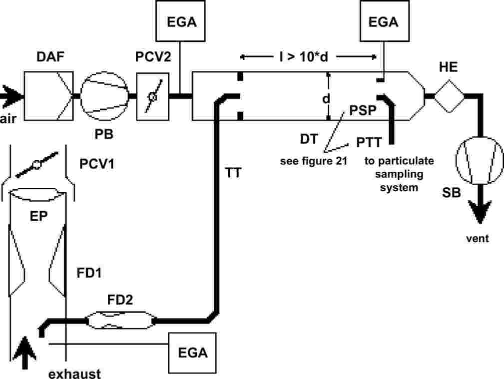
Raw exhaust gas is transferred from the exhaust pipe EP to the dilution tunnel DT through the sampling probe SP and the transfer tube TT by a flow divider that contains a set of orifices or venturis. The first one (FD1) is located in EP, the second one (FD2) in TT. Additionally, two pressure control valves (PCV1 and PCV2) are necessary to maintain a constant exhaust split by controlling the back-pressure in EP and the pressure in DT. PCV1 is located downstream of SP in EP, PCV2 between the pressure blower PB and DT. The tracer gas concentrations (CO2 or NOx) are measured in the raw exhaust gas, the diluted exhaust gas, and the dilution air with the exhaust gas analyser(s) EGA. They are necessary for checking the exhaust split, and may be used to adjust PCV1 and PCV2 for precise split control. The dilution ratio is calculated from the tracer gas concentrations.

Raw exhaust gas is transferred from the exhaust pipe EP to the dilution tunnel DT through the transfer tube TT by the flow divider FD3 that consists of a number of tubes of the same dimensions (same diameter, length and bend radius) installed in EP. The exhaust gas through one of these tubes is lead to DT, and the exhaust gas through the rest of the tubes is passed through the damping chamber DC. Thus, the exhaust split is determined by the total number of tubes. A constant split control requires a differential pressure of zero between DC and the outlet of TT, which is measured with the differential pressure transducer DPT. A differential pressure of zero is achieved by injecting fresh air into DT at the outlet of TT. The tracer gas concentrations (CO2 or NOx) are measured in the raw exhaust gas, the diluted exhaust gas, and the dilution air with the exhaust gas analyser(s) EGA. They are necessary for checking the exhaust split and may be used to control the injection air flow rate for precise split control. The dilution ratio is calculated from the tracer gas concentrations.

Raw exhaust gas is transferred from the exhaust pipe EP to the dilution tunnel DT through the sampling probe SP and the transfer tube TT. The total flow through the tunnel is adjusted with the flow controller FC3 and the sampling pump P of the particulate sampling system (see Figure 18). The dilution air flow is controlled by the flow controller FC2, which may use GEXHW, GAIRW, or GFUEL as command signals, for the desired exhaust split. The sample flow into DT is the difference of the total flow and the dilution air flow. The dilution air flow rate is measured with the flow measurement device FM1, the total flow rate with the flow measurement device FM3 of the particulate sampling system (see Figure 21). The dilution ratio is calculated from these two flow rates.

Raw exhaust gas is transferred from the exhaust pipe EP to the dilution tunnel DT through the sampling probe SP and the transfer tube TT. The exhaust split and the flow into DT is controlled by the flow controller FC2 that adjusts the flows (or speeds) of the pressure blower PB and the suction blower SB, accordingly. This is possible since the sample taken with the particulate sampling system is returned into DT. GEXHW, GAIRW, or GFUEL may be used as command signals for FC2. The dilution air flow rate is measured with the flow measurement device FM1, the total flow with the flow measurement device FM2. The dilution ratio is calculated from these two flow rates.
2.2.1. Components of Figures 11 to 19
|
EP |
Exhaust pipe |
The exhaust pipe may be insulated. To reduce the thermal inertia of the exhaust pipe a thickness to diameter ratio of 0,015 or less is recommended. The use of flexible sections must be limited to a length to diameter ratio of 12 or less. Bends must be minimised to reduce inertial deposition. If the system includes a test bed silencer the silencer may also be insulated.
For an isokinetic system, the exhaust pipe must be free of elbows, bends and sudden diameter changes for at least 6 pipe diameters upstream and 3 pipe diameters downstream of the tip of the probe. The gas velocity at the sampling zone must be higher than 10 m/s except at idle mode. Pressure oscillations of the exhaust gas must not exceed ± 500 Pa on the average. Any steps to reduce pressure oscillations beyond using a chassis-type exhaust system (including silencer and after-treatment devices) must not alter engine performance nor cause the deposition of particulates.
For systems without isokinetic probe, it is recommended to have a straight pipe of 6 pipe diameters upstream and 3 pipe diameters downstream of the tip of the probe.
|
SP |
Sampling probe (Figures 10, 14, 15, 16, 18, 19) |
The minimum inside diameter must be 4 mm. The minimum diameter ratio between exhaust pipe and probe must be 4. The probe must be an open tube facing upstream on the exhaust pipe centreline, or a multiple hole probe as described under SP1 in paragraph 1.2.1., Figure 5.
|
ISP |
Isokinetic sampling probe (Figures 11, 12) |
The isokinetic sampling probe must be installed facing upstream on the exhaust pipe centreline where the flow conditions in paragraph EP are met, and designed to provide a proportional sample of the raw exhaust gas. The minimum inside diameter must be 12 mm.
A control system is necessary for isokinetic exhaust splitting by maintaining a differential pressure of zero between EP and ISP. Under these conditions exhaust gas velocities in EP and ISP are identical and the mass flow through ISP is a constant fraction of the exhaust gas flow. ISP has to be connected to a differential pressure transducer DPT. The control to provide a differential pressure of zero between EP and ISP is done with the flow controller FC1.
|
FD1, FD2 |
Flow divider (Figure 16) |
A set of venturis or orifices is installed in the exhaust pipe EP and in the transfer tube TT, respectively, to provide a proportional sample of the raw exhaust gas. A control system consisting of two pressure control valves PCV1 and PCV2 is necessary for proportional splitting by controlling the pressures in EP and DT.
|
FD3 |
Flow divider (Figure 17) |
A set of tubes (multiple tube unit) is installed in the exhaust pipe EP to provide a proportional sample of the raw exhaust gas. One of the tubes feeds exhaust gas to the dilution tunnel DT, whereas the other tubes exit exhaust gas to a damping chamber DC. The tubes must have the same dimensions (same diameter, length, bend radius), so that the exhaust split depends on the total number of tubes. A control system is necessary for proportional splitting by maintaining a differential pressure of zero between the exit of the multiple tube unit into DC and the exit of TT. Under these conditions, exhaust gas velocities in EP and FD3 are proportional, and the flow TT is a constant fraction of the exhaust gas flow. The two points have to be connected to a differential pressure transducer DPT. The control to provide a differential pressure of zero is done with the flow controller FC1.
|
EGA |
Exhaust gas analyser (Figures 13, 14, 15, 16, 17) |
CO2 or NOx analysers may be used (with carbon balance method CO2 only). The analysers must be calibrated like the analysers for the measurement of the gaseous emissions. One or several analysers may be used to determine the concentration differences. The accuracy of the measuring systems has to be such that the accuracy of GEDFW,i is within ± 4 per cent.
|
TT |
Transfer tube (Figures 11 to 19) |
The transfer tube must be:
|
— |
As short as possible, but not more than 5 m in length. |
|
— |
Equal to or greater than the probe diameter, but not more than 25 mm in diameter. |
|
— |
Exiting on the centreline of the dilution tunnel and pointing downstream. |
If the tube is 1 meter or less in length, it must be insulated with material with a maximum thermal conductivity of 0,05 W/m × K with a radial insulation thickness corresponding to the diameter of the probe. If the tube is longer than 1 meter, it must be insulated and heated to a minimum wall temperature of 523 K (250 °C).
|
DPT |
Differential pressure transducer (Figures 11, 12, 17) |
The differential pressure transducer must have a range of ± 500 Pa or less.
|
FC1 |
Flow controller (Figures 11, 12, 17) |
For isokinetic systems (figures 11, 12), a flow controller is necessary to maintain a differential pressure of zero between EP and ISP. The adjustment can be done by:
|
(a) |
controlling the speed or flow of the suction blower SB and keeping the speed or flow of the pressure blower PB constant during each mode (Figure 11) or |
|
(b) |
adjusting the suction blower SB to a constant mass flow of the diluted exhaust gas and controlling the flow of the pressure blower PB, and therefore the exhaust sample flow in a region at the end of the transfer tube TT (Figure 12). |
In the case of a pressure controlled system the remaining error in the control loop must not exceed ± 3 Pa. The pressure oscillations in the dilution tunnel must not exceed ± 250 Pa on the average.
For a multi tube system (Figure 17), a flow controller is necessary for proportional exhaust splitting to maintain a differential pressure of zero between the exit of the multi tube unit and the exit of TT. The adjustment is done by controlling the injection air flow rate into DT at the exit of TT.
|
PCV1, PCV2 |
Pressure control valve (Figure 16) |
Two pressure control valves are necessary for the twin venturi/twin orifice system for proportional flow splitting by controlling the back-pressure of EP and the pressure in DT. The valves must be located downstream of SP in EP and between PB and DT.
|
DC |
Damping chamber (Figure 17) |
A damping chamber must be installed at the exit of the multiple tube unit to minimise the pressure oscillations in the exhaust pipe EP.
|
VN |
Venturi (Figure 15) |
A venturi is installed in the dilution tunnel DT to create a negative pressure in the region of the exit of the transfer tube TT. The gas flow rate through TT is determined by the momentum exchange at the venturi zone, and is basically proportional to the flow rate of the pressure blower PB leading to a constant dilution ratio. Since the momentum exchange is affected by the temperature at the exit of TT and the pressure difference between EP and DT, the actual dilution ratio is slightly lower at low load than at high load.
|
FC2 |
Flow controller (Figures 13, 14, 18, 19; optional) |
A flow controller may be used to control the flow of the pressure blower PB and/or the suction blower SB. It may be connected to the exhaust, intake air, or fuel flow signals and/or to the CO2 or NOx differential signals.
When using a pressurised air supply (Figure 18), FC2 directly controls the air flow.
|
FM1 |
Flow measurement device (Figures 11, 12, 18, 19) |
Gas meter or other flow instrumentation to measure the dilution air flow. FM1 is optional if the pressure blower PB is calibrated to measure the flow.
|
FM2 |
Flow measurement device (Figure 19) |
Gas meter or other flow instrumentation to measure the diluted exhaust gas flow. FM2 is optional if the suction blower SB is calibrated to measure the flow.
|
PB |
Pressure blower (Figures 11, 12, 13, 14, 15, 16, 19) |
To control the dilution air flow rate, PB may be connected to the flow controllers FC1 or FC2. PB is not required when using a butterfly valve. PB may be used to measure the dilution air flow, if calibrated.
|
SB |
Suction blower (Figures 11, 12, 13, 16, 17, 19) |
For fractional sampling systems only. SB may be used to measure the diluted exhaust gas flow, if calibrated.
|
DAF |
Dilution air filter (Figures 11 to 19) |
It is recommended that the dilution air be filtered and charcoal scrubbed to eliminate background hydrocarbons. At the engine manufacturers request the dilution air must be sampled according to good engineering practice to determine the background particulate levels, which can then be subtracted from the values measured in the diluted exhaust.
|
DT |
Dilution tunnel (Figures 11 to 19) |
The dilution tunnel:
|
— |
must be of a sufficient length to cause complete mixing of the exhaust and dilution air under turbulent flow conditions; |
|
— |
must be constructed of stainless steel with:
|
|
— |
must be at least 75 mm in diameter for the fractional sampling type; |
|
— |
is recommended to be at least 25 mm in diameter for the total sampling type; |
|
— |
may be heated to no greater than 325 K (52 °C) wall temperature by direct heating or by dilution air pre-heating, provided the air temperature does not exceed 325 K (52 °C) prior to the introduction of the exhaust in the dilution tunnel; |
|
— |
may be insulated. |
The engine exhaust must be thoroughly mixed with the dilution air. For fractional sampling systems, the mixing quality must be checked after introduction into service by means of a CO2-profile of the tunnel with the engine running (at least four equally spaced measuring points). If necessary, a mixing orifice may be used.
Note: If the ambient temperature in the vicinity of the dilution tunnel (DT) is below 293 K (20 °C), precautions should be taken to avoid particle losses onto the cool walls of the dilution tunnel. Therefore, heating and/or insulating the tunnel within the limits given above is recommended.
At high engine loads, the tunnel may be cooled by a non-aggressive means such as a circulating fan, as long as the temperature of the cooling medium is not below 293 K (20 °C).
|
HE |
Heat exchanger (Figures 16, 17) |
The heat exchanger must be of sufficient capacity to maintain the temperature at the inlet to the suction blower SB within ± 11 K of the average operating temperature observed during the test.
2.3. Full flow dilution system
A dilution system is described in Figure 20 based upon the dilution of the total exhaust using the CVS (Constant Volume Sampling) concept. The total volume of the mixture of exhaust and dilution air must be measured. Either a PDP or a CFV system may be used.
For subsequent collection of the particulates, a sample of the dilute exhaust gas is passed to the particulate sampling system (paragraph 2.4., Figures 21 and 22). If this is done directly, it is referred to as single dilution. If the sample is diluted once more in the secondary dilution tunnel, it is referred to as double dilution. This is useful, if the filter face temperature requirement cannot be met with single dilution. Although partly a dilution system, the double dilution system is described as a modification of a particulate sampling system in paragraph 2.4., Figure 22, since it shares most of the parts with a typical particulate sampling system.
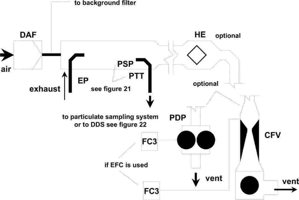
The total amount of raw exhaust gas is mixed in the dilution tunnel DT with the dilution air. The diluted exhaust gas flow rate is measured either with a Positive Displacement Pump PDP or with a Critical Flow Venturi CFV. A heat exchanger HE or electronic flow compensation EFC may be used for proportional particulate sampling and for flow determination. Since particulate mass determination is based on the total diluted exhaust gas flow, the dilution ratio is not required to be calculated.
2.3.1. Components of Figure 20
|
EP |
Exhaust pipe |
The exhaust pipe length from the exit of the engine exhaust manifold, turbocharger outlet or after-treatment device to the dilution tunnel must not exceed 10 m. If the exhaust pipe downstream of the engine exhaust manifold, turbocharger outlet or after-treatment device exceeds 4 m in length, then all tubing in excess of 4 m must be insulated, except for an in-line smokemeter, if used. The radial thickness of the insulation must be at least 25 mm. The thermal conductivity of the insulating material must have a value no greater than 0,1 W/mK measured at 673 K. To reduce the thermal inertia of the exhaust pipe a thickness to diameter ratio of 0,015 or less is recommended. The use of flexible sections must be limited to a length to diameter ratio of 12 or less.
|
PDP |
Positive displacement pump |
The PDP meters total diluted exhaust flow from the number of the pump revolutions and the pump displacement. The exhaust system back-pressure must not be artificially lowered by the PDP or dilution air inlet system. Static exhaust back-pressure measured with the PDP system operating must remain within ± 1,5 kPa of the static pressure measured without connection to the PDP at identical engine speed and load. The gas mixture temperature immediately ahead of the PDP must be within ± 6 K of the average operating temperature observed during the test, when no flow compensation is used. Flow compensation may only be used if the temperature at the inlet to the PDP does not exceed 323 K (50 °C)
|
CFV |
Critical flow venturi |
CFV measures total diluted exhaust flow by maintaining the flow at choked conditions (critical flow). Static exhaust back-pressure measured with the CFV system operating must remain within ± 1,5 kPa of the static pressure measured without connection to the CFV at identical engine speed and load. The gas mixture temperature immediately ahead of the CFV must be within ± 11 K of the average operating temperature observed during the test, when no flow compensation is used.
|
HE |
Heat exchanger (optional, if EFC is used) |
The heat exchanger must be of sufficient capacity to maintain the temperature within the limits required above.
|
EFC |
Electronic flow compensation (optional, if HE is used) |
If the temperature at the inlet to either the PDP or CFV is not kept within the limits stated above, a flow compensation system is required for continuous measurement of the flow rate and control of the proportional sampling in the particulate system. To that purpose, the continuously measured flow rate signals are used to correct the sample flow rate through the particulate filters of the particulate sampling system (see paragraph 2.4., Figures 21, 22), accordingly.
|
DT |
Dilution tunnel |
The dilution tunnel:
|
— |
must be small enough in diameter to cause turbulent flow (Reynolds Number greater than 4 000) and of sufficient length to cause complete mixing of the exhaust and dilution air; a mixing orifice may be used; |
|
— |
must be at least 460 mm in diameter with a single dilution system; |
|
— |
must be at least 210 mm in diameter with a double dilution system; |
|
— |
may be insulated. |
The engine exhaust must be directed downstream at the point where it is introduced into the dilution tunnel, and thoroughly mixed.
When using single dilution, a sample from the dilution tunnel is transferred to the particulate sampling system (paragraph 2.4., Figure 21). The flow capacity of the PDP or CFV must be sufficient to maintain the diluted exhaust at a temperature of less than or equal to 325 K (52 °C) immediately before the primary particulate filter.
When using double dilution, a sample from the dilution tunnel is transferred to the secondary dilution tunnel where it is further diluted, and then passed through the sampling filters (paragraph 2.4., Figure 22). The flow capacity of the PDP or CFV must be sufficient to maintain the diluted exhaust stream in the DT at a temperature of less than or equal to 464 K (191 °C) at the sampling zone. The secondary dilution system must provide sufficient secondary dilution air to maintain the doubly-diluted exhaust stream at a temperature of less than or equal to 325 K (52 °C) immediately before the primary particulate filter.
|
DAF |
Dilution air filter |
It is recommended that the dilution air be filtered and charcoal scrubbed to eliminate background hydrocarbons. At the engine manufacturers request the dilution air must be sampled according to good engineering practice to determine the background particulate levels, which can then be subtracted from the values measured in the diluted exhaust.
|
PSP |
Particulate sampling probe |
The probe is the leading paragraph of PTT and:
|
— |
must be installed facing upstream at a point where the dilution air and exhaust gas are well mixed, i.e. on the dilution tunnel (DT) centreline approximately 10 tunnel diameters downstream of the point where the exhaust enters the dilution tunnel; |
|
— |
must be of 12 mm minimum inside diameter; |
|
— |
may be heated to no greater than 325 K (52 °C) wall temperature by direct heating or by dilution air pre-heating, provided the air temperature does not exceed 325 K (52 °C) prior to the introduction of the exhaust in the dilution tunnel; |
|
— |
may be insulated. |
2.4. Particulate sampling system
The particulate sampling system is required for collecting the particulates on the particulate filter. In the case of total sampling partial flow dilution, which consists of passing the entire diluted exhaust sample through the filters, dilution (paragraph 2.2., Figures 14, 18) and sampling system usually form an integral unit. In the case of fractional sampling partial flow dilution or full flow dilution, which consists of passing through the filters only a portion of the diluted exhaust, the dilution (paragraph 2.2., Figures 11, 12, 13, 15, 16, 17, 19; paragraph 2.3., Figure 20) and sampling systems usually form different units.
In this Regulation, the double dilution system (Figure 22) of a full flow dilution system is considered as a specific modification of a typical particulate sampling system as shown in Figure 21. The double dilution system includes all important parts of the particulate sampling system, like filter holders and sampling pump, and additionally some dilution features, like a dilution air supply and a secondary dilution tunnel.
In order to avoid any impact on the control loops, it is recommended that the sample pump be running throughout the complete test procedure. For the single filter method, a bypass system must be used for passing the sample through the sampling filters at the desired times. Interference of the switching procedure on the control loops must be minimised.

A sample of the diluted exhaust gas is taken from the dilution tunnel DT of a partial flow or full flow dilution system through the particulate sampling probe PSP and the particulate transfer tube PTT by means of the sampling pump P. The sample is passed through the filter holder(s) FH that contain the particulate sampling filters. The sample flow rate is controlled by the flow controller FC3. If electronic flow compensation EFC (see Figure 20) is used, the diluted exhaust gas flow is used as command signal for FC3.

A sample of the diluted exhaust gas is transferred from the dilution tunnel DT of a full flow dilution system through the particulate sampling probe PSP and the particulate transfer tube PTT to the secondary dilution tunnel SDT, where it is diluted once more. The sample is then passed through the filter holder(s) FH that contain the particulate sampling filters. The dilution air flow rate is usually constant whereas the sample flow rate is controlled by the flow controller FC3. If electronic flow compensation EFC (see Figure 20) is used, the total diluted exhaust gas flow is used as command signal for FC3.
2.4.1. Components of Figures 21 and 22
|
PTT |
Particulate transfer tube (Figures 21, 22) |
The particulate transfer tube must not exceed 1 020 mm in length, and must be minimised in length whenever possible. Where applicable (i.e. for partial flow dilution fractional sampling systems and for full flow dilution systems), the length of the sampling probes (SP, ISP, PSP, respectively, see paragraphs 2.2. and 2.3.) must be included.
The dimensions are valid for:
|
— |
the partial flow dilution fractional sampling type and the full flow single dilution system from the tip of the probe (SP, ISP, PSP, respectively) to the filter holder; |
|
— |
the partial flow dilution total sampling type from the end of the dilution tunnel to the filter holder; |
|
— |
the full flow double dilution system from the tip of the probe (PSP) to the secondary dilution tunnel. |
The transfer tube:
|
— |
may be heated to no greater than 325K (52 °C) wall temperature by direct heating or by dilution air pre-heating, provided the air temperature does not exceed 325 K (52 °C) prior to the introduction of the exhaust in the dilution tunnel; |
|
— |
may be insulated. |
|
SDT |
Secondary dilution tunnel (Figure 22) |
The secondary dilution tunnel should have a minimum diameter of 75 mm, and should be of sufficient length so as to provide a residence time of at least 0,25 seconds for the doubly-diluted sample. The primary filter holder FH must be located within 300 mm of the exit of the SDT.
The secondary dilution tunnel:
|
— |
may be heated to no greater than 325 K (52 °C) wall temperature by direct heating or by dilution air pre-heating, provided the air temperature does not exceed 325 K (52 °C) prior to the introduction of the exhaust in the dilution tunnel; |
|
— |
may be insulated. |
|
FH |
Filter holder(s) (Figures 21, 22) |
For primary and back-up filters one filter housing or separate filter housings may be used. The requirements of annex 4, appendix 4, paragraph 4.1.3. must be met.
The filter holder(s):
|
— |
may be heated to no greater than 325 K (52 °C) wall temperature by direct heating or by dilution air pre-heating, provided the air temperature does not exceed 325 K (52 °C) prior to the introduction of the exhaust in the dilution tunnel; |
|
— |
may be insulated. |
|
P |
Sampling pump (Figures 21, 22) |
The particulate sampling pump must be located sufficiently distant from the tunnel so that the inlet gas temperature is maintained constant (± 3 K), if flow correction by FC3 is not used.
|
DP |
Dilution air pump (Figure 22) |
The dilution air pump must be located so that the secondary dilution air is supplied at a temperature of 298 K ± 5 K (25 °C ± 5 °C), if the dilution air is not preheated.
|
FC3 |
Flow controller (Figures 21, 22) |
A flow controller must be used to compensate the particulate sample flow rate for temperature and back pressure variations in the sample path, if no other means are available. The flow controller is required if electronic flow compensation EFC (see Figure 20) is used.
|
FM3 |
Flow measurement device (Figures 21, 22) |
The gas meter or flow instrumentation for the particulate sample flow must be located sufficiently distant from the sampling pump P so that the inlet gas temperature remains constant (± 3 K), if flow correction by FC3 is not used.
|
FM4 |
Flow measurement device (Figure 22) |
The gas meter or flow instrumentation for the dilution air flow must be located so that the inlet gas temperature remains at 298 K ± 5 K (25 °C ± 5 °C).
|
BV |
Ball valve (optional) |
The ball valve must have an inside diameter not less than the inside diameter of the particulate transfer tube PTT, and a switching time of less than 0,5 seconds.
Note: If the ambient temperature in the vicinity of PSP, PTT, SDT, and FH is below 293 K (20 °C), precautions should be taken to avoid particle losses onto the cool wall of these parts. Therefore, heating and/or insulating these parts within the limits given in the respective descriptions is recommended. It is also recommended that the filter face temperature during sampling be not below 293 K (20 °C).
At high engine loads, the above parts may be cooled by a non-aggressive means such as a circulating fan, as long as the temperature of the cooling medium is not below 293 K (20 °C).
3. DETERMINATION OF SMOKE OPACITY
3.1. Introduction
Paragraphs 3.2. and 3.3. and Figures 23 and 24 contain detailed descriptions of the recommended opacimeter systems. Since various configurations can produce equivalent results, exact conformance with Figures 23 and 24 is not required. Additional components such as instruments, valves, solenoids, pumps, and switches may be used to provide additional information and coordinate the functions of the component systems. Other components, which are not needed to maintain the accuracy on some systems, may be excluded if their exclusion is based upon good engineering judgement.
The principle of measurement is that light is transmitted through a specific length of the smoke to be measured and that proportion of the incident light which reaches a receiver is used to assess the light obscuration properties of the medium. The smoke measurement depends upon the design of the apparatus, and may be done in the exhaust pipe (full flow in-line opacimeter), at the end of the exhaust pipe (full flow end-of-line opacimeter) or by taking a sample from the exhaust pipe (partial flow opacimeter). For the determination of the light absorption coefficient from the opacity signal, the optical path length of the instrument must be supplied by the instrument manufacturer.
3.2. Full Flow Opacimeter
Two general types of full flow opacimeters may be used (Figure 23). With the in-line opacimeter, the opacity of the full exhaust plume within the exhaust pipe is measured. With this type of opacimeter, the effective optical path length is a function of the opacimeter design.
With the end-of-line opacimeter, the opacity of the full exhaust plume is measured as it exits the exhaust pipe. With this type of opacimeter, the effective optical path length is a function of the exhaust pipe design and the distance between the end of the exhaust pipe and the opacimeter.

3.2.1. Components of Figure 23
|
EP |
Exhaust Pipe |
With an in-line opacimeter, there must be no change in the exhaust pipe diameter within 3 exhaust pipe diameters before or after the measuring zone. If the diameter of the measuring zone is greater than the diameter of the exhaust pipe, a pipe gradually convergent before the measuring zone is recommended.
With an end-of-line opacimeter, the terminal 0,6 m of the exhaust pipe must be of circular cross section and be free from elbows and bends. The end of the exhaust pipe must be cut off squarely. The opacimeter must be mounted centrally to the plume within 25 ± 5 mm of the end of the exhaust pipe.
|
OPL |
Optical Path Length |
The length of the smoke obscured optical path between the opacimeter light source and the receiver, corrected as necessary for non-uniformity due to density gradients and fringe effect. The optical path length must be submitted by the instrument manufacturer taking into account any measures against sooting (e.g. purge air). If the optical path length is not available, it must be determined in accordance with ISO IDS 11614, paragraph 11.6.5. For the correct determination of the optical path length, a minimum exhaust gas velocity of 20 m/s is required.
|
LS |
Light source |
The light source must be an incandescent lamp with a colour temperature in the range of 2 800 to 3 250 K or a green light emitting diode (LED) with a spectral peak between 550 and 570 nm. The light source must be protected against sooting by means that do not influence the optical path length beyond the manufacturers specifications.
|
LD |
Light detector |
The detector must be a photocell or a photodiode (with a filter, if necessary). In the case of an incandescent light source, the receiver must have a peak spectral response similar to the phototopic curve of the human eye (maximum response) in the range of 550 to 570 nm, to less than 4 per cent of that maximum response below 430 nm and above 680 nm. The light detector must be protected against sooting by means that do not influence the optical path length beyond the manufacturers specifications.
|
CL |
Collimating lens |
The light output must be collimated to a beam with a maximum diameter of 30 mm. The rays of the light beam must be parallel within a tolerance of 3° of the optical axis.
|
T1 |
Temperature sensor (optional) |
The exhaust gas temperature may be monitored over the test.
3.3. Partial Flow Opacimeter
With the partial flow opacimeter (Figure 24), a representative exhaust sample is taken from the exhaust pipe and passed through a transfer line to the measuring chamber. With this type of opacimeter, the effective optical path length is a function of the opacimeter design. The response times referred to in the following paragraph apply to the minimum flow rate of the opacimeter, as specified by the instrument manufacturer.

3.3.1. Components of Figure 24
|
EP |
Exhaust pipe |
The exhaust pipe must be a straight pipe of at least 6 pipe diameters upstream and 3 pipe diameters downstream of the tip of the probe.
|
SP |
Sampling probe |
The sampling probe must be an open tube facing upstream on or about the exhaust pipe centreline. The clearance with the wall of the tailpipe must be at least 5 mm. The probe diameter must ensure a representative sampling and a sufficient flow through the opacimeter.
|
TT |
Transfer tube |
The transfer tube must:
|
— |
Be as short as possible and ensure an exhaust gas temperature of 373 ± 30 K (100 °C ± 30 °C) at the entrance to the measuring chamber. |
|
— |
Have a wall temperature sufficiently above the dew point of the exhaust gas to prevent condensation. |
|
— |
Be equal to the diameter of the sampling probe over the entire length. |
|
— |
Have a response time of less than 0,05 s at minimum instrument flow, as determined according to annex 4, appendix 4, paragraph 5.2.4. |
|
— |
Have no significant effect on the smoke peak. |
|
FM |
Flow measurement device |
Flow instrumentation to detect the correct flow into the measuring chamber. The minimum and maximum flow rates must be specified by the instrument manufacturer, and must be such that the response time requirement of TT and the optical path length specifications are met. The flow measurement device may be close to the sampling pump, P, if used.
|
MC |
Measuring chamber |
The measuring chamber must have a non-reflective internal surface, or equivalent optical environment. The impingement of stray light on the detector due to internal reflections of diffusion effects must be reduced to a minimum.
The pressure of the gas in the measuring chamber must not differ from the atmospheric pressure by more than 0,75 kPa. Where this is not possible by design, the opacimeter reading must be converted to atmospheric pressure.
The wall temperature of the measuring chamber must be set to within ± 5 K between 343 K (70 °C) and 373 K (100 °C), but in any case sufficiently above the dew point of the exhaust gas to prevent condensation. The measuring chamber must be equipped with appropriate devices for measuring the temperature.
|
OPL |
Optical path length |
The length of the smoke obscured optical path between the opacimeter light source and the receiver, corrected as necessary for non-uniformity due to density gradients and fringe effect. The optical path length must be submitted by the instrument manufacturer taking into account any measures against sooting (e.g. purge air). If the optical path length is not available, it must be determined in accordance with ISO IDS 11614, paragraph 11.6.5.
|
LS |
Light source |
The light source must be an incandescent lamp with a colour temperature in the range of 2 800 to 3 250 K or a green light emitting diode (LED) with a spectral peak between 550 and 570 nm. The light source must be protected against sooting by means that do not influence the optical path length beyond the manufacturers specifications.
|
LD |
Light detector |
The detector must be a photocell or a photodiode (with a filter, if necessary). In the case of an incandescent light source, the receiver must have a peak spectral response similar to the phototopic curve of the human eye (maximum response) in the range of 550 to 570 nm, to less than 4 per cent of that maximum response below 430 nm and above 680 nm. The light detector must be protected against sooting by means that do not influence the optical path length beyond the manufacturers specifications.
|
CL |
Collimating lens |
The light output must be collimated to a beam with a maximum diameter of 30 mm. The rays of the light beam must be parallel within a tolerance of 3° of the optical axis.
|
T1 |
Temperature sensor |
To monitor the exhaust gas temperature at the entrance to the measuring chamber.
|
P |
Sampling pump (optional) |
A sampling pump downstream of the measuring chamber may be used to transfer the sample gas through the measuring chamber.
ANNEX 5
TECHNICAL CHARACTERISTICS OF REFERENCE FUEL FOR C.I. ENGINES PRESCRIBED FOR APPROVAL TESTS AND TO VERIFY CONFORMITY OF PRODUCTION
1. DIESEL FUEL (28)
|
Parameter |
Unit |
Limits (28) |
Test Method (29) |
Publication |
|
|
Minimum |
Maximum |
||||
|
Cetane number (30) |
|
52 |
54 |
ISO 5165 |
1998 (31) |
|
Density at 15 °C |
kg/m3 |
833 |
837 |
ISO 3675 |
1995 |
|
Distillation: |
|
|
|
|
|
|
— 50 % point |
°C |
245 |
|
ISO 3405 |
1998 |
|
— 95 % point |
°C |
345 |
350 |
ISO 3405 |
1998 |
|
— final boiling point |
°C |
— |
370 |
ISO 3405 |
1998 |
|
Flash point |
°C |
55 |
— |
EN 27719 |
1993 |
|
CFPP |
°C |
— |
–5 |
EN 116 |
1981 |
|
Viscosity at 40 °C |
mm2/s |
2,5 |
3,5 |
EN-ISO 3104 |
1996 |
|
Polycyclic aromatic hydrocarbons |
% m/m |
3,0 |
6,0 |
IP 391 (*) |
1995 |
|
Sulphur content (32) |
mg/kg |
— |
300 |
pr. EN-ISO/DIS 14596 |
1998 (31) |
|
Copper corrosion |
|
— |
1 |
EN-ISO 2160 |
1995 |
|
Conradson carbon residue (10 % DR) |
% m/m |
— |
0,2 |
EN-ISO 10370 |
|
|
Ash content |
% m/m |
— |
0,01 |
EN-ISO 6245 |
1995 |
|
Water content |
% m/m |
— |
0,05 |
EN-ISO 12937 |
1995 |
|
Neutralisation (strong acid) number |
mg OH/g |
— |
0,02 |
ASTM D 974-95 |
1998 (31) |
|
Oxidation stability (33) |
mg/ml |
— |
0,025 |
EN-ISO 12205 |
1996 |
2. ETHANOL FOR DIESEL ENGINES (34)
|
Parameter |
Unit |
Limits (35) |
Test Method (36) |
|
|
Minimum |
Maximum |
|||
|
Alcohol, mass |
% m/m |
92,4 |
— |
ASTM D 5501 |
|
Other alcohol than ethanol contained in total alcohol, mass |
% m/m |
— |
2 |
ASTM D 5501 |
|
Density at 15 °C |
kg/m3 |
795 |
815 |
ASTM D 4052 |
|
Ash content |
% m/m |
|
0,001 |
ISO 6245 |
|
Flash point |
°C |
10 |
|
ISO 2719 |
|
Acidity, calculated as acetic acid |
% m/m |
— |
0,0025 |
ISO 1388-2 |
|
Neutralisation (strong acid) number |
KOH mg/1 |
— |
1 |
|
|
Colour |
According to scale |
— |
10 |
ASTM D 1209 |
|
Dry residue at 100 °C |
mg/kg |
|
15 |
ISO 759 |
|
Water content |
% m/m |
|
6,5 |
ISO 760 |
|
Aldehydes calculated as acetic acid |
% m/m |
|
0,0025 |
ISO 1388-4 |
|
Sulphur content |
mg/kg |
— |
10 |
ASTM D 5453 |
|
Esters, calculated as ethylacetate |
% m/m |
— |
0,1 |
ASTM D 1617 |
ANNEX 6
TECHNICAL CHARACTERISTICS OF REFERENCE N.G. FUEL PRESCRIBED FOR APPROVAL TESTS AND TO VERIFY CONFORMITY OF PRODUCTION
Type: NATURAL GAS (NG)
European market fuels are available in two ranges:
|
— |
the H range, whose extreme reference fuels are GR and G23; |
|
— |
the L range, whose extreme reference fuels are G23 and G25. |
The characteristics of GR, G23 and G25 reference fuels are summarised below:
Reference fuel GR
|
Characteristics |
Units |
Basis |
Limits |
Test Method |
|
|
Min. |
Max. |
||||
|
Composition: |
|
|
|
|
|
|
Methane |
% mole |
87 |
84 |
89 |
|
|
Ethane |
% mole |
13 |
11 |
15 |
|
|
Balance (37) |
% mole |
— |
— |
1 |
ISO 6974 |
|
Sulphur content |
mg/m3 (38) |
— |
— |
10 |
ISO 6326-5 |
Reference fuel G23
|
Characteristics |
Units |
Basis |
Limits |
Test Method |
|
|
Min. |
Max. |
||||
|
Composition: |
|
|
|
|
|
|
Methane |
% mole |
92,5 |
91,5 |
93,5 |
|
|
Balance (39) |
% mole |
— |
— |
1 |
ISO 6974 |
|
N2 |
% mole |
7,5 |
6,5 |
8,5 |
|
|
Sulphur content |
mg/m3 (40) |
— |
— |
10 |
ISO 6326-5 |
Reference fuel G25
|
Characteristics |
Units |
Basis |
Limits |
Test Method |
|
|
Min. |
Max. |
||||
|
Composition: |
|
|
|
|
|
|
Methane |
% mole |
86 |
84 |
88 |
|
|
Balance (41) |
% mole |
— |
— |
1 |
ISO 6974 |
|
N2 |
% mole |
14 |
12 |
16 |
|
|
Sulphur content |
mg/m3 (42) |
— |
— |
10 |
ISO 6326-5 |
ANNEX 7
TYPE: LIQUEFIED PETROLEUM GAS (LPG)
|
Parameter |
Unit |
Limits |
Fuel A |
Limits |
Fuel B |
Test Method |
|
Minimum |
Maximum |
Minimum |
Maximum |
|||
|
Motor Octane Number |
|
92,5 (43) |
|
92,5 |
|
EN 589 Annex B |
|
Composition: |
|
|
|
|
|
|
|
C3 content |
% vol |
48 |
52 |
83 |
87 |
|
|
C4 content |
% vol |
48 |
52 |
13 |
17 |
ISO 7941 |
|
Olefins |
% vol |
|
12 |
|
14 |
|
|
Evaporation Residue |
mg/kg |
|
50 |
|
50 |
NFM 41015 |
|
Total sulphur content |
ppm mass (43) |
|
50 |
|
50 |
EN 24260 |
|
Hydrogen sulphide |
— |
|
None |
|
None |
ISO 8819 |
|
Copper strip corrosion |
rating |
|
class 1 |
|
class 1 |
ISO 6251 (44) |
|
Water at 0 °C |
|
|
free |
|
free |
visual inspection |
ANNEX 8
EXAMPLE OF CALCULATION PROCEDURE
1. ESC TEST
1.1. Gaseous emissions
The measurement data for the calculation of the individual mode results are shown below. In this example, CO and NOx are measured on a dry basis, HC on a wet basis. The HC concentration is given in propane equivalent (C3) and has to be multiplied by 3 to result in the C1 equivalent. The calculation procedure is identical for the other modes.
|
P (kW) |
Ta (K) |
Ha (g/kg) |
GEXH (kg) |
GAIRW (kg) |
GFUEL (kg) |
HC (ppm) |
CO (ppm) |
NOx (ppm) |
|
82,9 |
294,8 |
7,81 |
563,38 |
545,29 |
18,09 |
6,3 |
41,2 |
495 |
Calculation of the dry to wet correction factor KW,r (annex 4, appendix 1, paragraph 4.2.):
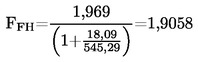 and
and ![]()

Calculation of the wet concentrations:
CO = 41,2 × 0,9239 = 38,1 ppm
NOx = 495 × 0,9239 = 457 ppm
Calculation of the NOx humidity correction factor KH,D (annex 4, appendix 1, paragraph 4.3.):
A = 0,309 × 18,09 / 541,06 – 0,0266 = –0,0163
B = –0,209 × 18,09 / 541,06 + 0,00954 = 0,0026

Calculation of the emission mass flow rates (annex 4, appendix 1, paragraph 4.4.):
NOx = 0,001587 × 457 × 0,9625 × 563,38 = 393,27 g/h
CO = 0,000966 × 38,1 × 563,38 = 20,735 g/h
HC = 0,000479 × 6,3 × 3 × 563,38 = 5,100 g/h
Calculation of the specific emissions (annex 4, appendix 1, paragraph 4.5.):
The following example calculation is given for CO; the calculation procedure is identical for the other components.
The emission mass flow rates of the individual modes are multiplied by the respective weighting factors, as indicated in annex 4, appendix 1, paragraph 2.7.1., and summed up to result in the mean emission mass flow rate over the cycle:
|
CO |
= |
(6,7 × 0,15) + (24,6 × 0,08) + (20,5 × 0,10) + (20,7 × 0,10) + (20,6 × 0,05) + (15,0 × 0,05) + (19,7 × 0,05) + (74,5 × 0,09) + (31,5 × 0,10) + (81,9 × 0,08) + (34,8 × 0,05) + (30,8 × 0,05) + (27,3 × 0,05) = 30,91 g/h |
The engine power of the individual modes is multiplied by the respective weighting factors, as indicated in annex 4, appendix 1, paragraph 2.7.1., and summed up to result in the mean cycle power:
|
P(n) |
= |
(0,1 × 0,15) + (96,8 × 0,08) + (55,2 × 0,10) + (82,9 × 0,10) + (46,8 × 0,05) + (70,1 × 0,05) + (23,0 × 0,05) + (114,3 × 0,09) + (27,0 × 0,10) + (122,0 × 0,08) + (28,6 × 0,05) + (87,4 × 0,05) + (57,9 × 0,05) = 60,006 kW |

Calculation of the specific NOx emission of the random point (annex 4, appendix 1, paragraph 4.6.1.):
Assume the following values have been determined on the random point:
|
nZ |
= 1 600 min–1 |
|
|
MZ |
= 495 Nm |
|
|
NOx mass,Z |
= 487,9 g/h |
(calculated according to the previous formulae) |
|
P(n)Z |
= 83 kW |
|
|
NOx,Z |
= 487,9 / 83 |
= 5,878 g/kWh |
Determination of the emission value from the test cycle (annex 4, appendix 1, paragraph 4.6.2.):
Assume the values of the four enveloping modes on the ESC to be as follows:
|
nRT |
nSU |
ER |
ES |
ET |
EU |
MR |
MS |
MT |
MU |
|
1 368 |
1 785 |
5,943 |
5,565 |
5,889 |
4,973 |
515 |
460 |
681 |
610 |
ETU = 5,889 + (4,973 – 5,889) × (1 600 – 1 368) / (1 785 – 1 368) = 5,377 g/kWh
ERS = 5,943 + (5,565 – 5,943) × (1 600 – 1 368) / (1 785 – 1 368) = 5,732 g/kWh
MTU = 681 + (601 – 681) × (1 600 – 1 368) / (1 785 – 1 368) = 641,3 Nm
MRS = 515 + (460 – 515) × (1 600 – 1 368) / (1 785 – 1 368) = 484,3 Nm
EZ = 5,732 + (5,377 – 5,732) × (495 – 484,3) / (641,3 – 484,3) = 5,708 g/kWh
Comparison of the NOx emission values (annex 4, appendix 1, paragraph 4.6.3.):
NOx diff = 100 × (5,878 – 5,708) / 5,708 = 2,98 %
1.2. Particulate Emissions
Particulate measurement is based on the principle of sampling the particulates over the complete cycle, but determining the sample and flow rates (MSAM and GEDF) during the individual modes. The calculation of GEDF depends on the system used. In the following examples, a system with CO2 measurement and carbon balance method and a system with flow measurement are used. When using a full flow dilution system, GEDF is directly measured by the CVS equipment.
Calculation of GEDF (annex 4, appendix 1, paragraphs 5.2.3. and 5.2.4.):
Assume the following measurement data of mode 4. The calculation procedure is identical for the other modes.
|
GEXH (kg/h) |
GFUEL (kg/h) |
GDILW (kg/h) |
GTOTW (kg/h) |
CO2D (%) |
CO2A (%) |
|
334,02 |
10,76 |
5,4435 |
6,0 |
0,657 |
0,040 |
|
a) |
carbon balance method 
|
|
b) |
flow measurement method |
GEDFW = 334,02 × 10,78 = 3 600,7 kg/h
Calculation of the mass flow rate (annex 4, appendix 1, paragraph 5.4.):
The GEDFW flow rates of the individual modes are multiplied by the respective weighting factors, as indicated in annex 4, appendix 1, paragraph 2.7.1., and summed up to result in the mean GEDF over the cycle. The total sample rate MSAM is summed up from the sample rates of the individual modes.
|
|
= |
(3 567 × 0,15) + (3 592 × 0,08) + (3 611 × 0,10) + (3 600 × 0,10) + (3 618 × 0,05) + (3 600 × 0,05) + (3 640 × 0,05) + (3 614 × 0,09) + (3 620 × 0,10) + (3 601 × 0,08) + (3 639 × 0,05) + (3 582 × 0,05) + (3 635 × 0,05) = 3 604,6 kg/h |
|
MSAM |
= |
0,226 + 0,122 + 0,151 + 0,152 + 0,076 + 0,076 + 0,076 + 0,136 + 0,151 + 0,121 + 0,076 + 0,076 + 0,075 = 1,515 kg |
Assume the particulate mass on the filters to be 2,5 mg, then

Background correction (optional)
Assume one background measurement with the following values. The calculation of the dilution factor DF is identical to paragraph 3.1. of this annex and not shown here.
Md = 0,1 mg; MDIL = 1,5 kg
Sum of DF = [(1–1 / 119,15) × 0,15] + [(1–1 / 8,89) × 0,08] + [(1–1 / 14,75) × 0,10] + [(1–1 / 10,10) × 0,10] + [(1–1 / 18,02) × 0,05] + [(1–1 / 12,33) × 0,05] + [(1–1 / 32,18) × 0,05] + [(1–1 / 6,94) × 0,09] + [(1–1 / 25,19) × 0,10] + [(1–1 / 6,12) × 0,08] + [(1–1 / 20,87) × 0,05] + [(1–1 / 8,77) × 0,05] + [(1–1 / 12,59) × 0,05] = 0,923

Calculation of the specific emission (annex 4, appendix 1, paragraph 5.5.):
|
P(n) |
= |
(0,1 × 0,15) + (96,8 × 0,08) + (55,2 × 0,10) + (82,9 × 0,10) + (46,8 × 0,05) + (70,1 × 0,05) + (23,0 × 0,05) + (114,3 × 0,09) + (27,0 × 0,10) + (122,0 × 0,08) + (28,6 × 0,05) + (87,4 × 0,05) + (57,9 × 0,05) = 60,006 kW |
 = 0,099 g/kWh, if background corrected
 = 0,095 g/kWh
Calculation of the specific weighting factor (annex 4, appendix 1, paragraph 5.6.):
Assume the values calculated for mode 4 above, then

This value is within the required value of 0,10 ± 0,003.
2. ELR TEST
Since Bessel filtering is a completely new averaging procedure in European exhaust legislation, an explanation of the Bessel filter, an example of the design of a Bessel algorithm, and an example of the calculation of the final smoke value is given below. The constants of the Bessel algorithm only depend on the design of the opacimeter and the sampling rate of the data acquisition system. It is recommended that the opacimeter manufacturer provide the final Bessel filter constants for different sampling rates and that the customer use these constants for designing the Bessel algorithm and for calculating the smoke values.
2.1. General remarks on the Bessel filter
Due to high frequency distortions, the raw opacity signal usually shows a highly scattered trace. To remove these high frequency distortions a Bessel filter is required for the ELR-Test. The Bessel filter itself is a recursive, second-order low-pass filter which guarantees the fastest signal rise without overshoot.
Assuming a real time raw exhaust plume in the exhaust tube, each opacimeter shows a delayed and differently measured opacity trace. The delay and the magnitude of the measured opacity trace is primarily dependent on the geometry of the measuring chamber of the opacimeter, including the exhaust sample lines, and on the time needed for processing the signal in the electronics of the opacimeter. The values that characterise these two effects are called the physical and the electrical response time which represent an individual filter for each type of opacimeter.
The goal of applying a Bessel filter is to guarantee a uniform overall filter characteristic of the whole opacimeter system, consisting of:
|
— |
physical response time of the opacimeter (tp) |
|
— |
electrical response time of the opacimeter (te) |
|
— |
filter response time of the applied Bessel filter (tF) |
The resulting overall response time of the system tAver is given by:

and must be equal for all kinds of opacimeters in order to give the same smoke value. Therefore, a Bessel filter has to be created in such a way, that the filter response time (tF) together with the physical (tp) and electrical response time (te) of the individual opacimeter must result in the required overall response time (tAver). Since tp and te are given values for each individual opacimeter, and tAver is defined to be 1,0 s in this Regulation, tF can be calculated as follows:

By definition, the filter response time tF is the rise time of a filtered output signal between 10 % and 90 % on a step input signal. Therefore the cut-off frequency of the Bessel filter has to be iterated in such a way, that the response time of the Bessel filter fits into the required rise time.

In figure (a), the traces of a step input signal and Bessel filtered output signal as well as the response time of the Bessel filter (tF) are shown.
Designing the final Bessel filter algorithm is a multi step process which requires several iteration cycles. The scheme of the iteration procedure is presented below.

2.2. Calculation of the Bessel algorithm
In this example a Bessel algorithm is designed in several steps according to the above iteration procedure which is based upon annex 4, appendix 1, paragraph 6.1.
For the opacimeter and the data acquisition system, the following characteristics are assumed:
|
— |
physical response time tp 0,15 s |
|
— |
electrical response time te 0,05 s |
|
— |
overall response time tAver 1,00 s (by definition in this Regulation) |
|
— |
sampling rate 150 Hz |
Step 1 Required Bessel filter response time tF:

Step 2 Estimation of cut-off frequency and calculation of Bessel constants E, K for first iteration:
fc = 3,1415 / (10 × 0,987421) = 0,318152 Hz
Δt = 1/150 = 0,006667 s
Ω = 1 / [tan (3,1415 × 0,006667 × 0,318152)] = 150,076644
![]()
K = 2 × 7,07948 × 10–5 × (0,618034 × 150,076644 – 1) – 1 = 0,970783
This gives the Bessel algorithm:
Yi = Yi –1 + 7,07948 × 10⁻⁵ × (Si + 2 × Si –1 + Si–2 – 4 × Yi–2) + 0,970783 × (Yi –1 – Yi–2)
where Si represents the values of the step input signal (either ‘0’ or ‘1’) and Yi represents the filtered values of the output signal.
Step 3 Application of Bessel filter on step input:
The Bessel filter response time tF is defined as the rise time of the filtered output signal between 10 % and 90 % on a step input signal. For determining the times of 10 % (t10) and 90 % (t90) of the output signal, a Bessel filter has to be applied to a step input using the above values of fc, E and K.
The index numbers, the time and the values of a step input signal and the resulting values of the filtered output signal for the first and the second iteration are shown in table B. The points adjacent to t10 and t90 are marked in bold numbers. In table B, first iteration, the 10 % value occurs between index number 30 and 31 and the 90 % value occurs between index number 191 and 192. For the calculation of tF,iter the exact t10 and t90 values are determined by linear interpolation between the adjacent measuring points, as follows:
t10 = tlower + Δt × (0,1 – outlower) / (outupper – outlower)
t90 = tlower + Δt × (0,9 – outlower) / (outupper – outlower)
where outupper and outlower, respectively, are the adjacent points of the Bessel filtered output signal, and tlower is the time of the adjacent time point, as indicated in table B.
t10 = 0,200000 + 0,006667 × (0,1 – 0,099208) / (0,104794 – 0,099208) = 0,200945 s
t90 = 1,273333 + 0,006667 × (0,9 – 0,899147) / (0,901168 – 0,899147) = 1,276147 s
Step 4 Filter response time of first iteration cycle:
tF,iter = 1,276147 – 0,200945 = 1,075202 s
Step 5 Deviation between required and obtained filter response time of first iteration cycle:
Δ = (1,075202 – 0,987421) / 0,987421 = 0,081641
Step 6 Checking the iteration criteria:
|Δ| ≤ 0,01 is required. Since 0,081641 > 0,01, the iteration criteria is not met and a further iteration cycle has to be started. For this iteration cycle, a new cut-off frequency is calculated from fc and Δ as follows:
fc,new = 0,318152 × (1 + 0,081641) = 0,344126 Hz
This new cut-off frequency is used in the second iteration cycle, starting at step 2 again. The iteration has to be repeated until the iteration criteria is met. The resulting values of the first and second iteration are summarised in table A.
Table A
Values of the first and second iteration
|
Parameter |
1. Iteration |
2. Iteration |
|
fc (Hz) |
0,318152 |
0,344126 |
|
E (–) |
7,07948 × 10⁻⁵ |
8,272777 × 10⁻⁵ |
|
K (–) |
0,970783 |
0,968410 |
|
t10 (s) |
0,200945 |
0,185523 |
|
t90 (s) |
1,276147 |
1,179562 |
|
tF,iter (s) |
1,075202 |
0,994039 |
|
Δ (–) |
0,081641 |
0,006657 |
|
fc,new (Hz) |
0,344126 |
0,346417 |
Step 7 Final Bessel algorithm:
As soon as the iteration criteria has been met, the final Bessel filter constants and the final Bessel algorithm are calculated according to step 2. In this example, the iteration criteria has been met after the second iteration (Δ = 0,006657 ≤ 0,01). The final algorithm is then used for determining the averaged smoke values (see next paragraph 2.3).
YI = Yi –1 + 8,272777 × 10⁻⁵ × (Si + 2 × Si –1 + Si–2 – 4 × Yi–2) + 0,968410 × (Yi –1 – Yi–2)
Table B
Values of step input signal and Bessel filtered output signal for the first and second iteration cycle
|
Index I [–] |
Time [s] |
Step Input Signal Si [–] |
Filtered Output Signal Yi [–] |
|
|
1. Iteration |
2. Iteration |
|||
|
–2 |
–0,013333 |
0 |
0,000000 |
0,000000 |
|
–1 |
–0,006667 |
0 |
0,000000 |
0,000000 |
|
0 |
0,000000 |
1 |
0,000071 |
0,000083 |
|
1 |
0,006667 |
1 |
0,000352 |
0,000411 |
|
2 |
0,013333 |
1 |
0,000908 |
0,001060 |
|
3 |
0,020000 |
1 |
0,001731 |
0,002019 |
|
4 |
0,026667 |
1 |
0,002813 |
0,003278 |
|
5 |
0,033333 |
1 |
0,004145 |
0,004828 |
|
~ |
~ |
~ |
~ |
~ |
|
24 |
0,160000 |
1 |
0,067877 |
0,077876 |
|
25 |
0,166667 |
1 |
0,072816 |
0,083476 |
|
26 |
0,173333 |
1 |
0,077874 |
0,089205 |
|
27 |
0,180000 |
1 |
0,083047 |
0,095056 |
|
28 |
0,186667 |
1 |
0,088331 |
0,101024 |
|
29 |
0,193333 |
1 |
0,093719 |
0,107102 |
|
30 |
0,200000 |
1 |
0,099208 |
0,113286 |
|
31 |
0,206667 |
1 |
0,104794 |
0,119570 |
|
32 |
0,213333 |
1 |
0,110471 |
0,125949 |
|
33 |
0,220000 |
1 |
0,116236 |
0,132418 |
|
34 |
0,226667 |
1 |
0,122085 |
0,138972 |
|
35 |
0,233333 |
1 |
0,128013 |
0,145605 |
|
36 |
0,240000 |
1 |
0,134016 |
0,152314 |
|
37 |
0,246667 |
1 |
0,140091 |
0,159094 |
|
~ |
~ |
~ |
~ |
~ |
|
175 |
1,166667 |
1 |
0,862416 |
0,895701 |
|
176 |
1,173333 |
1 |
0,864968 |
0,897941 |
|
177 |
1,180000 |
1 |
0,867484 |
0,900145 |
|
178 |
1,186667 |
1 |
0,869964 |
0,902312 |
|
179 |
1,193333 |
1 |
0,872410 |
0,904445 |
|
180 |
1,200000 |
1 |
0,874821 |
0,906542 |
|
181 |
1,206667 |
1 |
0,877197 |
0,908605 |
|
182 |
1,213333 |
1 |
0,879540 |
0,910633 |
|
183 |
1,220000 |
1 |
0,881849 |
0,912628 |
|
184 |
1,226667 |
1 |
0,884125 |
0,914589 |
|
185 |
1,233333 |
1 |
0,886367 |
0,916517 |
|
186 |
1,240000 |
1 |
0,888577 |
0,918412 |
|
187 |
1,246667 |
1 |
0,890755 |
0,920276 |
|
188 |
1,253333 |
1 |
0,892900 |
0,922107 |
|
189 |
1,260000 |
1 |
0,895014 |
0,923907 |
|
190 |
1,266667 |
1 |
0,897096 |
0,925676 |
|
191 |
1,273333 |
1 |
0,899147 |
0,927414 |
|
192 |
1,280000 |
1 |
0,901168 |
0,929121 |
|
193 |
1,286667 |
1 |
0,903158 |
0,930799 |
|
194 |
1,293333 |
1 |
0,905117 |
0,932448 |
|
195 |
1,300000 |
1 |
0,907047 |
0,934067 |
|
~ |
~ |
~ |
~ |
~ |
2.3. Calculation of the Smoke Values
In the scheme below the general procedure of determining the final smoke value is presented.

In figure b, the traces of the measured raw opacity signal, and of the unfiltered and filtered light absorption coefficients (k-value) of the first load step of an ELR-Test are shown, and the maximum value Ymax1,A (peak) of the filtered k trace is indicated. Correspondingly, table C contains the numerical values of index i, time (sampling rate of 150 Hz), raw opacity, unfiltered k and filtered k. Filtering was conducted using the constants of the Bessel algorithm designed in paragraph 2.2. of this annex. Due to the large amount of data, only those sections of the smoke trace around the beginning and the peak are tabled.
The peak value (i = 272) is calculated assuming the following data of table C. All other individual smoke values are calculated in the same way. For starting the algorithm, s–1, s–2, y–1 and y–2 are set to zero.

Calculation of the k-value (annex 4, appendix 1, paragraph 6.3.1.):
|
LA (m) |
0,430 |
|
Index I |
272 |
|
N (%) |
16,783 |
|
S271 (m–1) |
0,427392 |
|
S270 (m–1) |
0,427532 |
|
Y271 (m–1) |
0,542383 |
|
Y270 (m–1) |
0,542337 |

This value corresponds to S272 in the equation that follows.
Calculation of Bessel averaged smoke (annex 4, appendix 1, paragraph 6.3.2.):
In the following equation, the Bessel constants of the previous paragraph 2.2. are used. The actual unfiltered k-value, as calculated above, corresponds to S272 (Si). S271 (Si –1) and S270 (Si–2) are the two preceding unfiltered k-values, Y271 (Yi –1) and Y270 (Yi-2) are the two preceding filtered k-values.
|
Y272 |
= |
0,542383 + 8,272777 × 10–5 × (0,427252 + 2 × 0,427392 + 0,427532 – 4 × 0,542337) + 0,968410 × (0,542383 – 0,542337) = 0,542389 m–1 |
This value corresponds to Ymax1,A in the following equation.
Calculation of the final smoke value (annex 4, appendix 1, paragraph 6.3.3.):
From each smoke trace, the maximum filtered k-value is taken for the further calculation. Assume the following values:
|
Speed |
Ymax (m–1) |
||
|
Cycle 1 |
Cycle 2 |
Cycle 3 |
|
|
A |
0,5424 |
0,5435 |
0,5587 |
|
B |
0,5596 |
0,5400 |
0,5389 |
|
C |
0,4912 |
0,5207 |
0,5177 |
|
SVA |
= |
(0,5424 + 0,5435 + 0,5587) / 3 |
= |
0,5482 m–1 |
|
SVB |
= |
(0,5596 + 0,5400 + 0,5389) / 3 |
= |
0,5462 m–1 |
|
SVC |
= |
(0,4912 + 0,5207 + 0,5177) / 3 |
= |
0,5099 m–1 |
|
SV |
= |
(0,43 × 0,5482) + (0,56 × 0,5462) + (0,01 × 0,5099) |
= |
0,5467 m–1 |
Cycle validation (annex 4, appendix 1, paragraph 3.4.)
Before calculating SV, the cycle must be validated by calculating the relative standard deviations of the smoke of the three cycles for each speed.
|
Speed |
Mean SV (m–1) |
absolute standard deviation (m–1) |
relative standard deviation (%) |
|
A |
0,5482 |
0,0091 |
1,7 |
|
B |
0,5462 |
0,0116 |
2,1 |
|
C |
0,5099 |
0,0162 |
3,2 |
In this example, the validation criteria of 15 per cent is met for each speed.
Table C
Values of opacity N, unfiltered and filtered k-value at beginning of load step
|
Index i [–] |
Time [s] |
Opacity N [%] |
Unfiltered k-Value [m–1] |
Filtered k-Value [m–1] |
|
–2 |
0,000000 |
0,000000 |
0,000000 |
0,000000 |
|
–1 |
0,000000 |
0,000000 |
0,000000 |
0,000000 |
|
0 |
0,000000 |
0,000000 |
0,000000 |
0,000000 |
|
1 |
0,006667 |
0,020000 |
0,000465 |
0,000000 |
|
2 |
0,013333 |
0,020000 |
0,000465 |
0,000000 |
|
3 |
0,020000 |
0,020000 |
0,000465 |
0,000000 |
|
4 |
0,026667 |
0,020000 |
0,000465 |
0,000001 |
|
5 |
0,033333 |
0,020000 |
0,000465 |
0,000002 |
|
6 |
0,040000 |
0,020000 |
0,000465 |
0,000002 |
|
7 |
0,046667 |
0,020000 |
0,000465 |
0,000003 |
|
8 |
0,053333 |
0,020000 |
0,000465 |
0,000004 |
|
9 |
0,060000 |
0,020000 |
0,000465 |
0,000005 |
|
10 |
0,066667 |
0,020000 |
0,000465 |
0,000006 |
|
11 |
0,073333 |
0,020000 |
0,000465 |
0,000008 |
|
12 |
0,080000 |
0,020000 |
0,000465 |
0,000009 |
|
13 |
0,086667 |
0,020000 |
0,000465 |
0,000011 |
|
14 |
0,093333 |
0,020000 |
0,000465 |
0,000012 |
|
15 |
0,100000 |
0,192000 |
0,004469 |
0,000014 |
|
16 |
0,106667 |
0,212000 |
0,004935 |
0,000018 |
|
17 |
0,113333 |
0,212000 |
0,004935 |
0,000022 |
|
18 |
0,120000 |
0,212000 |
0,004935 |
0,000028 |
|
19 |
0,126667 |
0,343000 |
0,007990 |
0,000036 |
|
20 |
0,133333 |
0,566000 |
0,013200 |
0,000047 |
|
21 |
0,140000 |
0,889000 |
0,020767 |
0,000061 |
|
22 |
0,146667 |
0,929000 |
0,021706 |
0,000082 |
|
23 |
0,153333 |
0,929000 |
0,021706 |
0,000109 |
|
24 |
0,160000 |
1,263000 |
0,029559 |
0,000143 |
|
25 |
0,166667 |
1,455000 |
0,034086 |
0,000185 |
|
26 |
0,173333 |
1,697000 |
0,039804 |
0,000237 |
|
27 |
0,180000 |
2,030000 |
0,047695 |
0,000301 |
|
28 |
0,186667 |
2,081000 |
0,048906 |
0,000378 |
|
29 |
0,193333 |
2,081000 |
0,048906 |
0,000469 |
|
30 |
0,200000 |
2,424000 |
0,057067 |
0,000573 |
|
31 |
0,206667 |
2,475000 |
0,058282 |
0,000693 |
|
32 |
0,213333 |
2,475000 |
0,058282 |
0,000827 |
|
33 |
0,220000 |
2,808000 |
0,066237 |
0,000977 |
|
34 |
0,226667 |
3,010000 |
0,071075 |
0,001144 |
|
35 |
0,233333 |
3,253000 |
0,076909 |
0,001328 |
|
36 |
0,240000 |
3,606000 |
0,085410 |
0,001533 |
|
37 |
0,246667 |
3,960000 |
0,093966 |
0,001758 |
|
38 |
0,253333 |
4,455000 |
0,105983 |
0,002007 |
|
39 |
0,260000 |
4,818000 |
0,114836 |
0,002283 |
|
40 |
0,266667 |
5,020000 |
0,119776 |
0,002587 |
|
~ |
~ |
~ |
~ |
~ |
Table C (continued)
Values of opacity N, unfiltered and filtered k-value around Ymax1,A
(≡ peak value, indicated in bold number)
|
Index i [–] |
Time [s] |
Opacity N [%] |
Unfiltered k-Value [m–1] |
Filtered k-Value [m–1] |
|
~ |
~ |
~ |
~ |
~ |
|
259 |
1,726667 |
17,182000 |
0,438429 |
0,538856 |
|
260 |
1,733333 |
16,949000 |
0,431896 |
0,539423 |
|
261 |
1,740000 |
16,788000 |
0,427392 |
0,539936 |
|
262 |
1,746667 |
16,798000 |
0,427671 |
0,540396 |
|
263 |
1,753333 |
16,788000 |
0,427392 |
0,540805 |
|
264 |
1,760000 |
16,798000 |
0,427671 |
0,541163 |
|
265 |
1,766667 |
16,798000 |
0,427671 |
0,541473 |
|
266 |
1,773333 |
16,788000 |
0,427392 |
0,541735 |
|
267 |
1,780000 |
16,788000 |
0,427392 |
0,541951 |
|
268 |
1,786667 |
16,798000 |
0,427671 |
0,542123 |
|
269 |
1,793333 |
16,798000 |
0,427671 |
0,542251 |
|
270 |
1,800000 |
16,793000 |
0,427532 |
0,542337 |
|
271 |
1,806667 |
16,788000 |
0,427392 |
0,542383 |
|
272 |
1,813333 |
16,783000 |
0,427252 |
0,542389 |
|
273 |
1,820000 |
16,780000 |
0,427168 |
0,542357 |
|
274 |
1,826667 |
16,798000 |
0,427671 |
0,542288 |
|
275 |
1,833333 |
16,778000 |
0,427112 |
0,542183 |
|
276 |
1,840000 |
16,808000 |
0,427951 |
0,542043 |
|
277 |
1,846667 |
16,768000 |
0,426833 |
0,541870 |
|
278 |
1,853333 |
16,010000 |
0,405750 |
0,541662 |
|
279 |
1,860000 |
16,010000 |
0,405750 |
0,541418 |
|
280 |
1,866667 |
16,000000 |
0,405473 |
0,541136 |
|
281 |
1,873333 |
16,010000 |
0,405750 |
0,540819 |
|
282 |
1,880000 |
16,000000 |
0,405473 |
0,540466 |
|
283 |
1,886667 |
16,010000 |
0,405750 |
0,540080 |
|
284 |
1,893333 |
16,394000 |
0,416406 |
0,539663 |
|
285 |
1,900000 |
16,394000 |
0,416406 |
0,539216 |
|
286 |
1,906667 |
16,404000 |
0,416685 |
0,538744 |
|
287 |
1,913333 |
16,394000 |
0,416406 |
0,538245 |
|
288 |
1,920000 |
16,394000 |
0,416406 |
0,537722 |
|
289 |
1,926667 |
16,384000 |
0,416128 |
0,537175 |
|
290 |
1,933333 |
16,010000 |
0,405750 |
0,536604 |
|
291 |
1,940000 |
16,010000 |
0,405750 |
0,536009 |
|
292 |
1,946667 |
16,000000 |
0,405473 |
0,535389 |
|
293 |
1,953333 |
16,010000 |
0,405750 |
0,534745 |
|
294 |
1,960000 |
16,212000 |
0,411349 |
0,534079 |
|
295 |
1,966667 |
16,394000 |
0,416406 |
0,533394 |
|
296 |
1,973333 |
16,394000 |
0,416406 |
0,532691 |
|
297 |
1,980000 |
16,192000 |
0,410794 |
0,531971 |
|
298 |
1,986667 |
16,000000 |
0,405473 |
0,531233 |
|
299 |
1,993333 |
16,000000 |
0,405473 |
0,530477 |
|
300 |
2,000000 |
16,000000 |
0,405473 |
0,529704 |
|
~ |
~ |
~ |
~ |
~ |
3. ETC TEST
3.1. Gaseous emissions (diesel engine)
Assume the following test results for a PDP-CVS system
|
V0 |
(m3/rev) |
0,1776 |
|
Np |
(rev) |
23 073 |
|
pB |
(kPa) |
98,0 |
|
p1 |
(kPa) |
2,3 |
|
T |
(K) |
322,5 |
|
Ha |
(g/kg) |
12,8 |
|
NOx conce |
(ppm) |
53,7 |
|
NOx concd |
(ppm) |
0,4 |
|
COconce |
(ppm) |
38,9 |
|
COconcd |
(ppm) |
1,0 |
|
HCconce |
(ppm) without cutter |
9,00 |
|
HCconcd |
(ppm) without cutter |
3,02 |
|
HCconce |
(ppm) with cutter |
1,20 |
|
HCconcd |
(ppm) with cutter |
0,65 |
|
CO2, conce |
(%) |
0,723 |
|
Wact |
(kWh) |
62,72 |
Calculation of the diluted exhaust gas flow (annex 4, appendix 2, paragraph 4.1.):
|
MTOTW |
= 1,293 × 0,1776 × 23 073 × (98,0 – 2,3) × 273 / (101,3 × 322,5) = 4 237,2 kg |
Calculation of the NOx correction factor (annex 4, appendix 2, paragraph 4.2.):
![]()
Calculation of the NMHC concentration by NMC method (annex 4, appendix 2, paragraph 4.3.1.), assuming a methane efficiency of 0,04 and an ethane efficiency of 0,98:


Calculation of the background corrected concentrations (annex 4, appendix 2, paragraph 4.3.1.1.):
Assuming a diesel fuel of the composition C1H1,8
![]()

|
NOx conc |
= |
53,7 – 0,4 · (1 – (1 / 18,69)) |
= |
53,3 ppm |
|
COconc |
= |
38,9 – 1,0 · (1 – (1 / 18,69)) |
= |
37,9 ppm |
|
HCconc |
= |
9,00 – 3,02 · (1 – (1 / 18,69)) |
= |
6,14 ppm |
|
NMHCconc |
= |
7,91 – 2,39 · (1 – (1 / 18,69)) |
= |
5,65 ppm |
Calculation of the emissions mass flow (annex 4, appendix 2, paragraph 4.3.1.):
|
NOx mass |
= |
0,001587 · 53,3 · 1,039 · 4 237,2 |
= |
372,391 g |
|
COmass |
= |
0,000966 · 37,9 · 4 237,2 |
= |
155,129 g |
|
HCmass |
= |
0,000479 · 6,14 · 4 237,2 |
= |
12,462 g |
|
NMHCmass |
= |
0,000479 · 5,65 · 4 237,2 |
= |
11,467 g |
Calculation of the specific emissions (annex 4, appendix 2, paragraph 4.4.):


3.2. Particulate Emissions (Diesel Engine)
Assume the following test results for a PDP-CVS system with double dilution
|
MTOTW (kg) |
4 237,2 |
|
Mf,p (mg) |
3,030 |
|
Mf,b (mg) |
0,044 |
|
MTOT (kg) |
2,159 |
|
MSEC (kg) |
0,909 |
|
Md (mg) |
0,341 |
|
MDIL (kg) |
1,245 |
|
DF |
18,69 |
|
Wact (kWh) |
62,72 |
Calculation of the mass emission (annex 4, appendix 2, paragraph 5.1.):
Mf = 3,030 + 0,044 = 3,074 mg
MSAM = 2,159 – 0,909 = 1,250 kg

Calculation of the background corrected mass emission (annex 4, appendix 2, paragraph 5.1.):

Calculation of the specific emission (annex 4, appendix 2, paragraph 5.2):


3.3. Gaseous emissions (CNG engine)
Assume the following test results for a PDP-CVS system
|
MTOTW |
(kg) |
4 237,2 |
|
Ha |
(g/kg) |
12,8 |
|
NOx conce |
(ppm) |
17,2 |
|
NOx concd |
(ppm) |
0,4 |
|
COconce |
(ppm) |
44,3 |
|
COconcd |
(ppm) |
1,0 |
|
HCconce |
(ppm) without cutter |
27,0 |
|
HCconcd |
(ppm) without cutter |
2,02 |
|
HCconce |
(ppm) with cutter |
18,0 |
|
HCconcd |
(ppm) with cutter |
0,65 |
|
CH4 conce |
(ppm) |
18,0 |
|
CH4 concd |
(ppm) |
1,1 |
|
CO2,conce |
(%) |
0,723 |
|
Wact |
(kWh) |
62,72 |
Calculation of the NOx correction factor (annex 4, appendix 2, paragraph 4.2.):
![]()
Calculation of the NMHC concentration (annex 4, appendix 2, paragraph 4.3.1.):
|
a) |
GC method NMHCconce = 27,0 – 18,0 = 9,0 ppm |
|
b) |
NMC method |
Assuming a methane efficiency of 0,04 and an ethane efficiency of 0,98 (see annex 4, appendix 5, paragraph 1.8.4.)

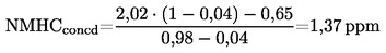
Calculation of the background corrected concentrations (annex 4, appendix 2, paragraph 4.3.1.1.):
Assuming a 100 % methane fuel of the composition C1H4
![]()

For NMHC with GC method, the background concentration is the difference between HCconcd and CH4 concd
|
NOx conc |
= 17,2 – 0,4 · (1 – (1/13,01)) = 16,8 ppm |
|
|
COconc |
= 44,3 – 1,0 · (1 – (1/13,01)) = 43,4 ppm |
|
|
NMHCconc |
= 8,4 – 1,37 · (1 – (1/13,01)) = 7,13 ppm |
(NMC method) |
|
NMHCconc |
= 9,0 – 0,92 · (1 – (1/13,01)) = 8,15 ppm |
(GC method) |
|
CH4 conc |
= 18,0 – 1,1 · (1 – (1/13,01)) = 17,0 ppm |
(GC method) |
Calculation of the emissions mass flow (annex 4, appendix 2, paragraph 4.3.1.):
|
NOx mass |
= 0,001587 · 16,8 · 1,074 · 4 237,2 = 121,330 g |
|
|
COmass |
= 0,000966 · 43,4 · 4 237,2 = 177,642 g |
|
|
NMHCmass |
= 0,000516 · 7,13 · 4 237,2 = 15,589 g |
(NMC method) |
|
NMHCmass |
= 0,000516 · 8,15 · 4 237,2 = 17,819 g |
(GC method) |
|
CH4 mass |
= 0,000552 · 17,0 · 4 237,2 = 39,762 g |
(GC method) |
Calculation of the specific emissions (annex 4, appendix 2, paragraph 4.4.):
|
|
= 121,330 / 62,72 |
= 1,93 g/kWh |
|
|
|
= 177,642 / 62,72 |
= 2,83 g/kWh |
|
|
|
= 15,589 / 62,72 |
= 0,249 g/kWh |
(NMC method) |
|
|
= 17,819 / 62,72 |
= 0,284 g/kWh |
(GC Method) |
|
|
= 39,762 / 62,72 |
= 0,634 g/kWh |
(GC method) |
4. λ-SHIFT FACTOR (Sλ)
4.1. Calculation of the λ-shift factor (Sλ) (45)

where:
|
Sλ |
= |
λ-shift factor; |
|
inert % |
= |
% by volume of inert gases in the fuel (i.e. N2, CO2, He, etc.); |
|
O2* |
= |
% by volume of original oxygen in the fuel; |
|
n and m |
= |
refer to average CnHm representing the fuel hydrocarbons, i.e: |


where:
|
CH4 |
= |
% by volume of methane in the fuel; |
|
C2 |
= |
% by volume of all C2 hydrocarbons (e.g.: C2H6, C2H4, etc.) in the fuel; |
|
C3 |
= |
% by volume of all C3 hydrocarbons (e.g.: C3H8, C3H6, etc.) in the fuel; |
|
C4 |
= |
% by volume of all C4 hydrocarbons (e.g.: C4H10, C4H8, etc.) in the fuel; |
|
C5 |
= |
% by volume of all C5 hydrocarbons (e.g.: C5H12, C5H10, etc.) in the fuel; |
|
diluent |
= |
% by volume of dilution gases in the fuel (i.e.: O2*, N2, CO2, He, etc.). |
4.2. Examples for the calculation of the λ-shift factor Sλ:
Example 1: G25: CH4 = 86 %, N2 = 14 % (by vol)


Example 2: GR: CH4 = 87 %, C2H6 = 13 % (by vol)


Example 3: USA: CH4 = 89 %, C2H6 = 4,5 %, C3H8 = 2,3 %, C6H14 = 0,2 %, O2 = 0.6 %, N2 = 4 %


ANNEX 9
SPECIFIC TECHNICAL REQUIREMENTS RELATING TO ETHANOL-FUELLED DIESEL ENGINES
In the case of ethanol-fuelled diesel engines, the following specific modifications to the appropriate paragraphs, equations and factors will apply to the test procedures defined in annex 4 to this Regulation.
In annex 4, appendix 1
4.2. Dry/wet correction

4.3. NOx correction for humidity and temperature
![]()
with:
|
A |
= |
0,181 GFUEL / GAIRD – 0,0266 |
|
B |
= |
–0,123 GFUEL / GAIRD + 0,00954 |
|
Ta |
= |
temperature of the air, K |
|
Ha |
= |
humidity of the intake air, g water per kg dry air |
4.4. Calculation of the emission mass flow rates
The emission mass flow rates (g/h) for each mode shall be calculated as follows, assuming the exhaust gas density to be 1 272 kg/m3 at 273 K (O°C) and 101,3 kPa:
|
(1) |
= |
NOx mass |
= |
0,001613 · NOx conc · KH,D · GEXHW |
|
(2) |
= |
COmass |
= |
0,000982 · COconc · GEXHW |
|
(3) |
= |
HCmass |
= |
0,000809 · HCconc · KH,D · GEXHW |
where NOx conc, COconc, HCconc (46) are the average concentrations (ppm) in the raw exhaust gas, as determined in paragraph 4.1.
If, optionally, the gaseous emissions are determined with a full flow dilution system, the following formulae must be applied:
|
(1) |
= |
NOx mass |
= |
0,001587 · NOx conc · KH,D · GTOTW |
|
(2) |
= |
COmass |
= |
0,000966 · COconc · GTOTW |
|
(3) |
= |
HCmass |
= |
0,000795 · HCconc · GTOTW |
where NOx conc, COconc, HCconc (46) are the average background corrected concentrations (ppm) of each mode in the diluted exhaust gas, as determined in annex 4, appendix 2, paragraph 4.3.1.1.
In annex 4, appendix 2
Paragraphs 3.1., 3.4., 3.8.3. and 5. of appendix 2 do not apply solely to diesel engines. They also apply to ethanol-fuelled diesel engines.
4.2. The conditions for the test should be arranged so that the air temperature and the humidity measured at the engine intake is set to standard conditions during the test run. The standard should be 6 ± 0,5 g water per kg dry air at a temperature interval of 298 ± 3 K. Within these limits no further NOx correction should be made. The test is void if these conditions are not met.
4.3. Calculation of the emission mass flow
4.3.1. Systems with constant mass flow
For systems with heat exchanger, the mass of the pollutants (g/test) must be determined from the following equations:
|
(1) |
= |
NOx mass |
= |
0,001587 · NOx conc · KH,D · MTOTW (ethanol fuelled engines) |
|
(2) |
= |
COmass |
= |
0,000966 · COconc · MTOTW (ethanol fuelled engines) |
|
(3) |
= |
HCmass |
= |
0,000794 · HCconc · MTOTW' (ethanol fuelled engines) |
where:
NOx conc, COconc, HCconc (46), NMHCconc = average background corrected concentrations over the cycle from integration (mandatory for NOx and HC) or bag measurement, ppm.
MTOTW = total mass of diluted exhaust gas over the cycle as determined in paragraph 4.1., kg.
4.3.1.1. Determination of the background corrected concentrations
The average background concentration of the gaseous pollutants in the dilution air must be subtracted from measured concentrations to get the net concentrations of the pollutants. The average values of the background concentrations can be determined by the sample bag method or by continuous measurement with integration. The following formula must be used.
conc = conce – concd × (1 – (1 / DF))
where:
|
conc |
= |
concentration of the respective pollutant in the diluted exhaust gas, corrected by the amount of the respective pollutant contained in the dilution air, ppm |
|
conce |
= |
concentration of the respective pollutant measured in the diluted exhaust gas, ppm |
|
concd |
= |
concentration of the respective pollutant measured in the dilution air, ppm |
|
DF |
= |
dilution factor |
The dilution factor must be calculated as follows:

where:
|
CO2,conce |
= |
concentration of CO2 in the diluted exhaust gas, % vol |
|
HCconce |
= |
concentration of HC in the diluted exhaust gas, ppm C1 |
|
COconce |
= |
concentration of CO in the diluted exhaust gas, ppm |
|
FS |
= |
stoichiometric factor |
Concentrations measured on dry basis must be converted to a wet basis in accordance with annex 4, appendix 1, paragraph 4.2.
The stoichiometric factor must, for the general fuel composition CHαOßNY, be calculated as follows:

Alternatively, if the fuel composition is not known, the following stoichiometric factors may be used:
FS (ethanol) = 12,3
4.3.2. Systems with flow compensation
For systems without heat exchanger, the mass of the pollutants (g/test) must be determined by calculating the instantaneous mass emissions and integrating the instantaneous values over the cycle. Also, the background correction must be applied directly to the instantaneous concentration value. The following formulae must be applied:
|
(1) |
= |
NOx mass |
= |
|
|
(2) |
= |
COmass |
= |
|
|
(3) |
= |
HCmass |
= |
|
where:
|
conce |
= |
concentration of the respective pollutant measured in the diluted exhaust gas, ppm |
|
concd |
= |
concentration of the respective pollutant measured in the dilution air, ppm |
|
MTOTW,I |
= |
instantaneous mass of the diluted exhaust gas (see paragraph 4.1.), kg |
|
MTOTW |
= |
total mass of diluted exhaust gas over the cycle (see paragraph 4.1.), kg |
|
DF |
= |
dilution factor as determined in paragraph 4.3.1.1. |
4.4. Calculation of the specific emissions
The emissions (g/kWh) must be calculated for all individual components in the following way:


where:
Wact = actual cycle work as determined in paragraph 3.9.2., kWh
(1) In conformity with annex 7 of the Consolidated Resolution on the Construction of Vehicles (R.E.3), (TRANS/WP.29/78/Rev.1/Amend.2).
(2) Engines used by category N1, N2 and M2 power-driven vehicles are not approved according to this Regulation, provided that such vehicles are approved according to Regulation No 83.
(3) 1 for Germany, 2 for France, 3 for Italy, 4 for the Netherlands, 5 for Sweden, 6 for Belgium, 7 for Hungary, 8 for the Czech Republic, 9 for Spain, 10 for Serbia and Montenegro, 11 for the United Kingdom, 12 for Austria, 13 for Luxembourg, 14 for Switzerland, 15 (vacant), 16 for Norway, 17 for Finland, 18 for Denmark, 19 for Romania, 20 for Poland, 21 for Portugal, 22 for the Russian Federation, 23 for Greece, 24 for Ireland, 25 for Croatia, 26 for Slovenia, 27 for Slovakia, 28 for Belarus, 29 for Estonia, 30 (vacant), 31 for Bosnia and Herzegovina, 32 for Latvia, 33 (vacant), 34 for Bulgaria, 35 (vacant), 36 for Lithuania, 37 for Turkey, 38 (vacant), 39 for Azerbaijan, 40 for The former Yugoslav Republic of Macedonia, 41 (vacant), 42 for the European Community (Approvals are granted by its Member States using their respective ECE symbol), 43 for Japan, 44 (vacant), 45 for Australia, 46 for Ukraine, 47 for South Africa, 48 for New Zealand, 49 for Cyprus, 50 for Malta and 51 for the Republic of Korea. Subsequent numbers shall be assigned to other countries in the chronological order in which they ratify or accede to the Agreement Concerning the Adoption of Uniform Technical Prescriptions for Wheeled Vehicles, Equipment and Parts which can be Fitted and/or be Used on Wheeled Vehicles and the Conditions for Reciprocal Recognition of Approvals Granted on the Basis of these Prescriptions, and the numbers thus assigned shall be communicated by the Secretary-General of the United Nations to the Contracting Parties to the Agreement.
(4) For engines having a swept volume of less than 0,75 dm3 per cylinder and a rated power speed of more than 3 000 min–1.
(5) For engines having a swept volume of less than 0,75 dm3 per cylinder and a rated power speed of more than 3 000 min–1.
(6) The conditions for verifying the acceptability of the ETC tests (see annex 4, appendix 2, paragraph 3.9.) when measuring the emissions of gas fuelled engines against the limit values applicable in row A must be re-examined and, where necessary, modified in accordance with the procedure laid down in Consolidated Resolution R.E.3.
(7) For NG engines only.
(8) Not applicable for gas fuelled engines at stage A and stages B1 and B2.
(9) In the case of non-conventional engines and systems, particulars equivalent to those referred to here must be supplied by the manufacturer.
(10) Strike out what does not apply.
(11) Specify the tolerance.
(12) In the case of systems laid out in a different manner, supply equivalent information (for paragraph 3.2).
(13) ESC test.
(14) ETC test only.
(15) Specify the tolerance; to be within ± 3 per cent of the values declared by the manufacturer.
(16) ESC test.
(17) ETC test only.
(18) If not applicable, mark ‘N/A’.
(19) To be submitted for each engine of the family.
(20) Strike out what does not apply.
(21) Specify the tolerance.
(22) The second Regulation number is given merely as an example.
(23) The test points must be selected using approved statistical methods of randomisation.
(24) The test points must be selected using approved statistical methods of randomisation.
(25) Based on C1 equivalent.
(26) The value is only valid for the reference fuel specified in the Regulation.
(27) Based on C1 equivalent.
(28) If it is required to calculate the thermal efficiency of an engine or vehicle, the calorific value of the fuel can be calculated from:
Specific energy (calorific value) (net) in MJ/kg = (46,423 – 8,792 d2 + 3,170 d) (1 – (x + y + s)) + 9,420 s – 2,499 x
where:
|
d |
= |
the density at 15 °C |
|
x |
= |
the proportion by mass of water (% divided by 100) |
|
y |
= |
the proportion by mass of ash (% divided by 100) |
|
s |
= |
the proportion by mass of sulphur (% divided by 100). |
(29) The values quoted in the specification are ‘true values’. In establishment of their limit values the terms of ISO 4259, Petroleum products - Determination and application of precision data in relation to methods of test, have been applied and in fixing a minimum value, a minimum difference of 2R above zero has been taken into account; in fixing a maximum and minimum value, the minimum difference is 4R (R - reproducibility). Notwithstanding this measure, which is necessary for statistical reasons, the manufacturer of a fuel should nevertheless aim at a zero value where the stipulated maximum value is 2R and at the mean value in the case of quotations of maximum and minimum limits. Should it be necessary to clarify the question as to whether a fuel meets the requirements of the specification, the terms of ISO 4259 should be applied.
(30) The range for cetane number is not in accordance with the requirement of a minimum range of 4R. However, in the case of dispute between fuel supplier and fuel user, the terms in ISO 4259 can be used to resolve such disputes provided replicate measurements, of sufficient number to achieve the necessary precision, are made in preference to single determinations.
(31) The month of publication will be completed in due course.
(32) The actual sulphur content of the fuel used for the test must be reported. In addition, the sulphur content of the reference fuel used to approve a vehicle or engine against the limit values set out in row B of the Table in paragraph 5.2.1. of this Regulation must have a maximum sulphur content of 50 ppm.
(33) Even though oxidation stability is controlled, it is likely that shelf life will be limited. Advice should be sought from the supplier as to storage conditions and life.
(34) Cetane improver, as specified by the engine manufacturer, may be added to the ethanol fuel. The maximum allowed amount is 10 % m/m.
(35) The values quoted in the specification are ‘true values’. In establishment of their limit values the terms of ISO 4259, Petroleum products – Determination and application of precision data in relation to methods of test, have been applied and in fixing a minimum value, a minimum difference of 2R above zero has been taken into account; in fixing a maximum and minimum value, the minimum difference is 4R (R – reproducibility). Notwithstanding this measure, which is necessary for statistical reasons, the manufacturer of a fuel should nevertheless aim at a zero value where the stipulated maximum value is 2R and at the mean value in the case of quotations of maximum and minimum limits. Should it be necessary to clarify the question as to whether a fuel meets the requirements of the specification, the terms of ISO 4259 should be applied.
(36) Equivalent ISO methods will be adopted when issued for all properties listed above.
(37) Inerts + C2+
(38) Value to be determined at standard conditions (293,2 K (20 °C) and 101,3 kPa).
(39) Inerts (different from N2) + C2/C2+.
(40) Value to be determined at standard conditions (293,2 K (20 °C) and 101,3 kPa).
(41) Inerts (different from N2) + C2/C2+.
(42) Value to be determined at standard conditions (293,2 K (20 °C) and 101,3 kPa).
(43) Value to be determined at standard conditions 293,2 K (20 °C) and 101,3 kPa.
(44) This method may not accurately determine the presence of corrosive materials if the sample contains corrosion inhibitors or other chemicals, which diminish the corrosivity of the sample to the copper strip. Therefore, the addition of such compounds for the sole purpose of biasing the test method is prohibited.
(45) Stoichiometric Air/Fuel ratios of automotive fuels: SAE J1829, June 1987.
John B. Heywood, Internal Combustion Engine Fundamentals, McGraw-Hill, 1988, Chapter 3.4. ‘Combustion stoichiometry’ (pages 68 to 72).
(46) Based on C1 equivalent.
|
9.3.2007 |
EN |
Official Journal of the European Union |
L 70/171 |
Corrigendum to Regulation No 83 of the Economic Commission for Europe of the United Nations (UN/ECE) — Uniform provisions concerning the approval of vehicles with regard to the emission of pollutants according to engine fuel requirements
( Official Journal of the European Union L 375 of 27 December 2006 )
Regulation No 83 should read as follows:
Regulation No 83 of the Economic Commission for Europe of the United Nations (UN/ECE) — Uniform provisions concerning the approval of vehicles with regard to the emission of pollutants according to engine fuel requirements
Revision 3
Incorporating all valid text up to:
Incorporating all valid text up to the 05 series of amendments — Date of entry into force: 29 March 2001
Supplement 1 to the 05 series of amendments — Date of entry into force: 12 September 2001
Supplement 2 to the 05 series of amendments — Date of entry into force: 21 February 2002
Corrigendum 1 to the 05 series of amendments subject of Depositary Notification C.N.111.2002.TREATIES-1 dated 8 February 2002
Corrigendum 2 to the 05 series of amendments subject of Depositary Notification C.N.883.2003.TREATIES-1 dated 2 September 2003
Supplement 3 to the 05 series of amendments — Date of entry into force: 27 February 2004
Supplement 4 to the 05 series of amendments — Date of entry into force: 12 August 2004
Corrigendum 3 to the 05 series of amendments subject of Depositary Notification C.N.1038.2004.TREATIES-1 dated 4 October 2004
Supplement 5 to the 05 series of amendments — Date of entry into force: 4 April 2005
1. SCOPE
This Regulation applies to (1):
1.1.1. Exhaust emissions at normal and low ambient temperature, evaporative emissions, emissions of crankcase gases, the durability of pollution control exhaust devices and on-board diagnostic (OBD) systems of motor vehicles equipped with positive-ignition (P.I.) engines which have at least 4 wheels.
1.1.2. Exhaust emissions, the durability of anti-pollution devices and on-board diagnostic (OBD) systems of vehicles of categories M1 and N1 equipped with compression-ignition (C.I.) engines which have at least 4 wheels and a maximum mass not exceeding 3 500 kg.
1.1.3. Exhaust emissions at normal and low ambient temperature, evaporative emissions, emissions of crankcase gases, the durability of pollution control exhaust devices and on-board diagnostic (OBD) systems of hybrid electric vehicles (HEV) equipped with positive-ignition (P.I.) engines and having at least four wheels.
1.1.4. Exhaust emissions, the durability of anti-pollution devices and on-board diagnostic (OBD) systems of hybrid electric vehicles (HEV) of categories M1 and N1 equipped with compression-ignition (C.I.) engines, having at least four wheels and a maximum mass not exceeding 3 500 kg.
1.1.5. It does not apply to:
|
— |
vehicles with a maximum mass of less than 400 kg and to vehicles having a maximum design speed of less than 50 km/h; |
|
— |
vehicles whose unladen mass is not more than 400 kg if they are intended for carrying passengers or 550 kg if they are intended for carrying goods and whose maximum engine power does not exceed 15 kW. |
1.1.6. At the request of the manufacturer, type approval pursuant to this Regulation may be extended from M1 or N1 vehicles equipped with compression-ignition engines which have already been typed approved to M2 and N2 vehicles having a reference mass not exceeding 2 840 kg and meeting the conditions of paragraph 7 (extension of approval).
1.1.7. Vehicles of category N1 equipped with compression-ignition engines or equipped with positive-ignition engines fuelled with NG or LPG are not subject to this Regulation provided they have been type-approved pursuant to Regulation No 49 as amended by the last series of amendments.
1.2. This Regulation does not apply to vehicles equipped with positive-ignition engines fuelled with NG or LPG used for driving motor vehicles of M1 category having a maximum mass exceeding 3 500 kg, M2, M3, N2, N3 to which Regulation No 49 is applicable.
2. DEFINITIONS
For the purposes of this Regulation:
‘Vehicle type’ means a category of power-driven vehicles that do not differ in such essential respects as:
2.1.1. the equivalent inertia determined in relation to the reference mass as prescribed in Annex 4, paragraph 5.1 and
2.1.2. the engine and vehicle characteristics as defined in Annex 1;
‘Reference mass’ means the ‘unladen mass’ of the vehicle increased by a uniform figure of 100 kg for test according to Annexes 4 and 8,
2.2.1. ‘Unladen mass’ means the mass of the vehicle in running order without driver, passengers or load, but with the fuel tank 90 per cent full and the usual set of tools and spare wheel on board, where applicable;
2.3. ‘Maximum mass’ means the technically permissible maximum mass declared by the vehicle manufacturer (this mass may be greater than the maximum mass authorised by the national administration);
2.4. ‘Gaseous pollutants’ means the exhaust gas emissions of carbon monoxide, oxides of nitrogen, expressed in nitrogen dioxide (NO2) equivalent and hydrocarbons assuming ratio of:
|
— |
C1H1,85 for petrol, |
|
— |
C1H1,86 for diesel, |
|
— |
C1H2,525 for LPG, |
|
— |
C1H4 for NG. |
2.5. ‘Particulate pollutants’ means components of the exhaust gas which are removed from the diluted exhaust gas at a maximum temperature of 325 K (52 °C) by means of the filters described in Annex 4;
2.6. ‘Exhaust emissions’ means:
|
— |
for positive-ignition (P.I.) engines, emissions of gaseous pollutants; |
|
— |
for compression-ignition (C.I.) engines, emissions of gaseous and particulate pollutants; |
‘Evaporative emissions’ means the hydrocarbon vapours lost from the fuel system of a motor vehicle other than those from exhaust emissions;
2.7.1. ‘Tank breathing losses’ are hydrocarbon emissions caused by temperature changes in the fuel tank (assuming a ratio of C1H2,33).
2.7.2. ‘Hot soak losses’ are hydrocarbon emissions arising from the fuel system of a stationary vehicle after a period of driving (assuming a ratio of C1H2,20);
2.8. ‘Engine crankcase’ means the spaces in or external to an engine which are connected to the oil sump by internal or external ducts through which gases and vapour can escape;
2.9. ‘Cold start device’ means a device that temporarily enriches the air/fuel mixture of the engine thus assisting the engine to start;
2.10. ‘Starting aid’ means a device which assists engine start up without enrichment of the air/fuel mixture of the engine, e.g. glow plug, injection timing change, etc.;
‘Engine capacity’ means:
2.11.1. For reciprocating piston engines, the nominal engine swept volume;
2.11.2. For rotary piston engines (Wankel), twice the nominal swept volume of a combustion chamber per piston;
2.12. ‘Pollution control devices’ means those components of a vehicle that control and/or limit exhaust and evaporative emissions.
2.13. ‘OBD’ means an on-board diagnostic system for emission control, which has the capability of identifying the likely area of malfunction by means of fault codes stored in computer memory;
2.14. ‘In-service test’ means the test and evaluation of conformity conducted in accordance with paragraph 8.2.1 of this Regulation;
2.15. ‘Properly maintained and used’ means, for the purpose of a test vehicle, that such a vehicle satisfies the criteria for acceptance of a selected vehicle laid down in paragraph 2 of Appendix 3 to this Regulation;
‘Defeat device’ means any element of design which senses temperature, vehicle speed, engine rotational speed, transmission gear, manifold vacuum or any other parameter for the purpose of activating, modulating, delaying or deactivating the operation of any part of the emission control system, that reduces the effectiveness of the emission control system under conditions which may reasonably be expected to be encountered in normal vehicle operation and use. Such an element of design may not be considered a defeat device if:
2.16.1. the need for the device is justified in terms of protecting the engine against damage or accident and for safe operation of the vehicle, or
2.16.2. the device does not function beyond the requirements of engine starting, or
2.16.3. conditions are substantially included in the Type I or Type VI test procedures.
2.17. ‘Family of vehicles’ means a group of vehicle types identified by a parent vehicle for the purpose of Annex 12;
2.18. ‘Fuel requirement by the engine’ means the type of fuel normally used by the engine:
|
— |
petrol, |
|
— |
LPG (liquefied petroleum gas), |
|
— |
NG (natural gas), |
|
— |
either petrol or LPG, |
|
— |
either petrol or NG, |
|
— |
diesel fuel; |
‘Approval of a vehicle’ means the approval of a vehicle type with regard to the limitation of the following conditions (2):
2.19.1. Limitation of exhaust emissions by the vehicle, evaporative emissions, crankcase emissions, durability of pollution control devices, cold start pollutant emissions and on-board diagnostics of vehicles fuelled with unleaded petrol, or which can be fuelled with either unleaded petrol and LPG or NG (Approval B);
2.19.2. Limitation of emissions of gaseous and particulate pollutants, durability of pollution control devices and on-board diagnostics of vehicles fuelled with diesel fuel (Approval C);
2.19.3. Limitation of emissions of gaseous pollutants by the engine, crankcase emissions, durability of pollution control devices, cold start emissions and on-board diagnostics of vehicles fuelled with LPG or NG (Approval D);
2.20. ‘Periodically regenerating system’ means an anti-pollution device (e.g. catalytic converter, particulate trap) that requires a periodical regeneration process in less than 4 000 km of normal vehicle operation. During cycles where regeneration occurs, emission standards can be exceeded. If a regeneration of an anti-pollution device occurs at least once per Type I test and that has already regenerated at least once during vehicle preparation cycle, it will be considered as a continuously regenerating system which does not require a special test procedure. Annex 13 does not apply to continuously regenerating systems.
At the request of the manufacturer, the test procedure specific to periodically regenerating systems will not apply to a regenerative device if the manufacturer provides data to the type approval authority that, during cycles where regeneration occurs, emissions remain below the standards given in paragraph 5.3.1.4. applied for the concerned vehicle category after agreement of the technical service.
Hybrid vehicles (HV)
2.21.1. General definition of hybrid vehicles (HV):
‘Hybrid vehicle (HV)’ means a vehicle with at least two different energy converters and two different energy storage systems (on vehicle) for the purpose of vehicle propulsion.
2.21.2. Definition of hybrid electric vehicles (HEV):
‘Hybrid electric vehicle (HEV)’ means a vehicle that, for the purpose of mechanical propulsion, draws energy from both of the following on-vehicle sources of stored energy/power:
|
— |
a consumable fuel, |
|
— |
an electrical energy/power storage device (e.g.: battery, capacitor, flywheel/generator etc.). |
2.22. ‘Mono-fuel vehicle’ means a vehicle that is designed primarily for permanent running on LPG or NG, but may also have a petrol system for emergency purposes for starting only, where the petrol tank does not contain more than 15 litres of petrol;
2.23. ‘Bi-fuel vehicle’ means a vehicle that can run part-time on petrol and also part-time on either LPG or NG.
3. APPLICATION FOR APPROVAL
The application for approval of a vehicle type with regard to exhaust emissions, crankcase emissions, evaporative emissions and durability of pollution control devices, as well as to its on-board diagnostic (OBD) system shall be submitted by the vehicle manufacturer or by his authorized representative.
Should the application concern an on-board diagnostic (OBD) system, it shall be accompanied by the additional information required in paragraph 4.2.11.2.7 of Annex 1, together with:
a declaration by the manufacturer of:
3.1.1.1.1. in the case of vehicles equipped with positive-ignition engines, the percentage of misfires out of a total number of firing events that would result in emissions exceeding the limits given in paragraph 3.3.2 of Annex 11, if that percentage of misfire had been present from the start of a Type I test as described in paragraph 5.3.1 of Annex 4;
3.1.1.1.2. in the case of vehicles equipped with positive-ignition engines, the percentage of misfires out of a total number of firing events that could lead to an exhaust catalyst, or catalysts, overheating prior to causing irreversible damage;
3.1.1.2. detailed written information fully describing the functional operation characteristics of the OBD system, including a listing of all relevant parts of the vehicle's emission control system, i.e. sensors, actuators and components, that are monitored by the OBD system;
3.1.1.3. a description of the malfunction indicator (MI) used by the OBD system to signal the presence of a fault to a driver of the vehicle;
copies of other type approvals with the relevant data to enable extensions of approvals;
3.1.1.4. if applicable, the particulars of the vehicle family as referred to in Annex 11, Appendix 2.
3.1.2. For the tests described in paragraph 3. of Annex 11, a vehicle representative of the vehicle type or vehicle family fitted with the OBD system to be approved shall be submitted to the technical service responsible for the type approval test. If the technical service determines that the submitted vehicle does not fully represent the vehicle type or vehicle family described in Annex 11, Appendix 2, an alternative and if necessary an additional vehicle shall be submitted for test in accordance with paragraph 3 of Annex 11.
A model of the information document relating to exhaust emissions, evaporative emissions, durability and the on-board diagnostic (OBD) system is given in Annex 1. The information mentioned under paragraph 4.2.11.2.7.6 of Annex 1 is to be included in Appendix 1 ‘OBD — RELATED INFORMATION’ to the type-approval communication given in Annex 2.
3.2.1. Where appropriate, copies of other type approvals with the relevant data to enable extensions of approvals and establishment of deterioration factors shall be submitted.
3.3. For the tests described in paragraph 5. of this Regulation a vehicle representative of the vehicle type to be approved shall be submitted to the technical service responsible for the approval tests.
4. APPROVAL
4.1. If the vehicle type submitted for approval following this amendment meets the requirements of paragraph 5. below, approval of that vehicle type shall be granted.
4.2. An approval number shall be assigned to each type approved.
Its first two digits shall indicate the series of amendments according to which the approval was granted. The same Contracting Party shall not assign the same number to another vehicle type.
Notice of approval or of extension or refusal of approval of a vehicle type pursuant to this Regulation shall be communicated to the Parties to the Agreement which apply this Regulation by means of a form conforming to the model in Annex 2 to this Regulation.
4.3.1. In the event of amendment to the present text, for example, if new limit values are prescribed, the Parties to the Agreement shall be informed which vehicle types already approved comply with the new provisions.
There shall be affixed, conspicuously and in a readily accessible place specified on the approval form, to every vehicle conforming to a vehicle type approved under this Regulation, an international approval mark consisting of:
4.4.1. a circle surrounding the letter ‘E’ followed by the distinguishing number of the country that has granted approval (3);
4.4.2. the number of this Regulation, followed by the letter ‘R’, a dash and the approval number to the right of the circle described in paragraph 4.4.1.
4.4.3. However, the approval mark shall contain an additional character after the letter ‘R’, the purpose of which is to distinguish the emission limit values for which the approval has been granted. For those approvals issued to indicate compliance with the limits for the Type I test detailed in Row A of the table in paragraph 5.3.1.4.1 of this Regulation, the letter ‘R’ will be followed by the roman number ‘I’. For those approvals issued to indicate compliance with the limits for the Type I test detailed in Row B in the table to paragraph 5.3.1.4.1 of this Regulation, the letter ‘R’ will be followed by the roman number ‘II’.
4.5. If the vehicle conforms to a vehicle type approved, under one or more other Regulations annexed to the Agreement, in the country which has granted approval under this Regulation, the symbol prescribed in paragraph 4.4.1 need not be repeated; in such a case, the Regulation and approval numbers and the additional symbols of all the Regulations under which approval has been granted in the country which has granted approval under this Regulation shall be placed in vertical columns to the right of the symbol prescribed in paragraph 4.4.1.
4.6. The approval mark shall be clearly legible and be indelible.
4.7. The approval mark shall be placed close to or on the vehicle data plate.
4.8. Annex 3 to this Regulation gives examples of arrangements of the approval mark.
5. SPECIFICATIONS AND TESTS
Note: As an alternative to the requirements of this paragraph, vehicle manufacturers whose world-wide annual production is less than 10 000 units may obtain approval on the basis of the corresponding technical requirements specified in: the California Code of Regulations, Title 13, Paragraphs 1960.1 (f) (2) or (g) (1) and (g) (2), 1960.1 (p) applicable to 1996 and later model-year vehicles, 1968.1, 1976 and 1975, applicable to 1995 and later model year light-duty vehicles (California Code of Regulations is published by Barclays Publishing).
5.1. General
5.1.1. The components liable to affect the emission of pollutants shall be so designed, constructed and assembled as to enable the vehicle, in normal use, despite the vibration to which they may be subjected, to comply with the provisions of this Regulation.
The technical measures taken by the manufacturer shall be such as to ensure that in conformity with the provisions of this Regulation, exhaust gas and evaporative emissions are effectively limited throughout the normal life of the vehicle and under normal conditions of use. This will include the security of those hoses and their joints and connections, used within the emission control systems, which shall be so constructed as to conform with the original design intent. For exhaust emissions, these provisions are deemed to be met if the provisions of paragraphs 5.3.1.4 and 8.2.3.1 respectively are complied with. For evaporative emissions, these conditions are deemed to be met if the provisions of paragraphs 5.3.1.4 and 8.2.3.1 respectively are complied with.
5.1.2.1. The use of a defeat device is prohibited.
5.1.3. Inlet orifices of petrol tanks
5.1.3.1. Subject to paragraph 5.1.3.2, the inlet orifice of the petrol tank shall be so designed as to prevent the tank from being filled from a petrol pump delivery nozzle which has an external diameter of 23,6 mm or greater.
Paragraph 5.1.3.1 shall not apply to a vehicle in respect of which both of the following conditions are satisfied, i.e.:
5.1.3.2.1. the vehicle is so designed and constructed that no device designed to control the emission of gaseous pollutants shall be adversely affected by leaded petrol, and;
5.1.3.2.2. the vehicle is conspicuously, legibly and indelibly marked with the symbol for unleaded petrol, specified in ISO 2575:1982, in a position immediately visible to a person filling the petrol tank. Additional markings are permitted.
Provision shall be made to prevent excess evaporative emissions and fuel spillage caused by a missing fuel filler cap.
This may be achieved by using one of the following:
5.1.4.1. an automatically opening and closing, non-removable fuel filler cap,
5.1.4.2. design features which avoid excess evaporative emissions in the case of a missing fuel filler cap,
5.1.4.3. any other provision which has the same effect. Examples may include, but are not limited to, a tethered filler cap, a chained filler cap or one utilising the same locking key for the filler cap as for the vehicle's ignition. In this case, the key shall be removable from the filler cap only in the locked condition.
5.1.5. Provisions for electronic system security
5.1.5.1. Any vehicle with an emission control computer shall include features to deter modification, except as authorised by the manufacturer. The manufacturer shall authorise modifications if these modifications are necessary for the diagnosis, servicing, inspection, retrofitting or repair of the vehicle. Any reprogrammable computer codes or operating parameters shall be resistant to tampering and afford a level of protection at least as good as the provisions in ISO DIS 15031-7, dated October 1998 (SAE J2 186 dated October 1996), provided that the security exchange is conducted using the protocols and diagnostic connector as prescribed in paragraph 6.5 of Annex II, Appendix 1. Any removable calibration memory chips shall be potted, encased in a sealed container or protected by electronic algorithms and shall not be changeable without the use of specialised tools and procedures.
5.1.5.2. Computer-coded engine operating parameters shall not be changeable without the use of specialised tools and procedures (e. g. soldered or potted computer components or sealed (or soldered) computer enclosures).
5.1.5.3. In the case of mechanical fuel-injection pumps fitted to compression-ignition engines, manufacturers shall take adequate steps to protect the maximum fuel delivery setting from tampering while a vehicle is in service.
5.1.5.4. Manufacturers may apply to the approval authority for an exemption to one of these requirements for those vehicles which are unlikely to require protection. The criteria that the approval authority will evaluate in considering an exemption will include, but are not limited to, the current availability of performance chips, the high-performance capability of the vehicle and the projected sales volume of the vehicle.
5.1.5.5. Manufacturers using programmable computer code systems (e.g. Electrical Erasable Programmable Read-Only Memory, EEPROM) shall deter unauthorised reprogramming. Manufacturers shall include enhanced tamper protection strategies and write protect features requiring electronic access to an off-site computer maintained by the manufacturer. Methods giving an adequate level of tamper protection will be approved by the authority.
5.1.6. It shall be possible to inspect the vehicle for roadworthiness test in order to determine its performance in relation to the data collected in accordance with paragraph 5.3.7 of this Regulation. If this inspection requires a special procedure, this shall be detailed in the service manual (or equivalent media). This special procedure shall not require the use of special equipment other than that provided with the vehicle.
5.2. Test procedure
Table 1 illustrates the various possibilities for type approval of a vehicle.
5.2.1. Positive ignition engine-powered vehicles and hybrid electric vehicles equipped with a positive-ignition engine shall be subject to the following tests:
|
— |
Type I (verifying the average exhaust emissions after a cold start) |
|
— |
Type II (carbon monoxide emission at idling speed) |
|
— |
Type III (emission of crankcase gases) |
|
— |
Type IV (evaporation emissions) |
|
— |
Type V (durability of anti-pollution devices) |
|
— |
Type VI (verifying the average low ambient temperature carbon monoxide and hydrocarbon exhaust emissions after a cold start |
|
— |
OBD-test. |
5.2.2. Positive ignition engine-powered vehicle and hybrid electric vehicles equipped with positive-ignition engine fuelled with LPG or NG (mono or bi-fuel) shall be subjected to the following tests (according to Table 1):
|
— |
Type I (verifying the average exhaust emissions after a cold start) |
|
— |
Type II (carbon monoxide emissions at idling speed) |
|
— |
Type III (emission of crankcase gases) |
|
— |
Type IV (evaporative emissions), where applicable |
|
— |
Type V (durability of anti-pollution devices) |
|
— |
Type VI (verifying the average low ambient temperature carbon monoxide and hydrocarbon exhaust emissions after a cold start), where applicable |
|
— |
OBD test, where applicable. |
5.2.3. Compression ignition engine-powered vehicles and hybrid electric vehicles equipped with a compression ignition engine shall be subject to the following tests:
|
— |
Type I (verifying the average exhaust emissions after a cold start) |
|
— |
Type V (durability of anti-pollution control devices) |
|
— |
and, where applicable, OBD test. |
Table 1
Different routes for type approval and extensions
|
Type-approval test |
Positive-ignition engined vehicles of categories M and N |
Compression-ignition engined vehicles of categories M1 and N1 |
||
|
petrol fuelled vehicle |
bi-fuel vehicle |
mono-fuel vehicle |
|
|
|
Type I |
Yes (maximum mass ≤ 3,5 t) |
Yes (test with both fuel types) (maximum mass ≤ 3,5 t) |
Yes (maximum mass ≤ 3,5 t) |
Yes (maximum mass ≤ 3,5 t) |
|
Type II |
Yes |
Yes (test with both fuel types) |
Yes |
— |
|
Type III |
Yes |
Yes (test only with petrol) |
Yes |
— |
|
Type IV |
Yes (maximum mass ≤ 3,5 t) |
Yes (test only with petrol) (maximum mass ≤ 3,5 t) |
— |
— |
|
Type V |
Yes (maximum mass ≤ 3,5 t) |
Yes (test only with petrol) (maximum mass ≤ 3,5 t) |
Yes (maximum mass ≤ 3,5 t) |
Yes (maximum mass ≤ 3,5 t) |
|
Type VI |
Yes (maximum mass ≤ 3,5 t) |
Yes (maximum mass ≤ 3,5 t) (test only with petrol) |
— |
— |
|
Extension |
Paragraph 7 |
Paragraph 7 |
Paragraph 7 |
Paragraph 7; M2 and N2 with a reference mass ≤ 2 840 kg |
|
On-board diagnostics |
Yes, in accordance with paragraph 11.1.5.1.1 or 11.1.5.3 |
Yes, in accordance with paragraph 11.1.5.1.2 or 11.1.5.3 |
Yes, in accordance with paragraph 11.1.5.1.2 or 11.1.5.3 |
Yes, in accordance with paragraph 11.1.5.2.1 or 11.1.5.2.2 or 11.1.5.2.3 or 11.1.5.3 |
5.3. Description of tests
5.3.1. Type I test (Simulating the average exhaust emissions after a cold start).
5.3.1.1. Figure 1 illustrates the routes for Type I test. This test shall be carried out on all vehicles referred to in paragraph 1, having a maximum mass not exceeding 3,5 tonnes.
The vehicle is placed on a chassis dynamometer equipped with a means of load and inertia simulation.
A test lasting a total of 19 minutes and 40 seconds, made up of two parts, One and Two, is performed without interruption. An unsampled period of not more than 20 seconds may, with the agreement of the manufacturer, be introduced between the end of Part One and the beginning of Part Two in order to facilitate adjustment of the test equipment.
5.3.1.2.1.1. Vehicles that are fuelled with LPG or NG shall be tested in the Type I test for variation in the composition of LPG or NG, as set out in Annex 12. Vehicles that can be fuelled either with petrol or LPG or NG shall be tested on both the fuels, tests on LPG or NG being performed for variation in the composition of LPG or NG, as set out in Annex 12.
5.3.1.2.1.2. Notwithstanding the requirement of paragraph 5.3.1.2.1.1, vehicles that can be fuelled with either petrol or a gaseous fuel, but where the petrol system is fitted for emergency purposes or starting only and which the petrol tank cannot contain more than 15 litres of petrol will be regarded for the test Type I as vehicles that can only run on a gaseous fuel.
5.3.1.2.2. Part One of the test is made up of four elementary urban cycles. Each elementary urban cycle comprises fifteen phases (idling, acceleration, steady speed, deceleration, etc.).
5.3.1.2.3. Part Two of the test is made up of one extra-urban cycle. The extra-urban cycle comprises 13 phases (idling, acceleration, steady speed, deceleration, etc.).
5.3.1.2.4. During the test, the exhaust gases are diluted and a proportional sample collected in one or more bags. The exhaust gases of the vehicle tested are diluted, sampled and analysed, following the procedure described below, and the total volume of the diluted exhaust is measured. Not only the carbon monoxide, hydrocarbon and nitrogen oxide emissions but also the particulate pollutant emissions from vehicles equipped with compression-ignition engines are recorded.
5.3.1.3. The test is carried out using the procedure described in Annex 4. The methods used to collect and analyse the gases and to remove and weigh the particulates shall be as prescribed.
Subject to the requirements of paragraph 5.3.1.5 the test shall be repeated three times. The results are multiplied by the appropriate deterioration factors obtained from paragraph 5.3.6 and, in the case of periodically regenerating systems as defined in paragraph 2.20, also must be multiplied by the factors Ki obtained from Annex 13. The resulting masses of gaseous emissions and, in the case of vehicles equipped with compression-ignition engines, the mass of particulates obtained in each test shall be less than the limits shown in the table below:
Limit Values
|
|
Reference mass (RW) (kg) |
Mass of carbon monoxide (CO) |
Mass of hydrocarbons (HC) |
Mass of oxides of nitrogen (NOx) |
Combined mass of hydrocarbons and oxides of nitrogen (HC + NOx) |
Mass of particulates (4) (PM) |
||||||
|
L1 (g/km) |
L2 (g/km) |
L3 (g/km) |
L2 + L3 (g/km) |
L4 (g/km) |
||||||||
|
Category |
Class |
|
Petrol |
Diesel |
Petrol |
Diesel |
Petrol |
Diesel |
Petrol |
Diesel |
Diesel |
|
|
A(2000) |
M (5) |
— |
All |
2,3 |
0,64 |
0,20 |
— |
0,15 |
0,50 |
— |
0,56 |
0,05 |
|
N1 (6) |
I |
RW ≤ 1 305 |
2,3 |
0,64 |
0,20 |
— |
0,15 |
0,50 |
— |
0,56 |
0,05 |
|
|
II |
1 305 < RW ≤ 1 760 |
4,17 |
0,80 |
0,25 |
— |
0,18 |
0,65 |
— |
0,72 |
0,07 |
||
|
III |
1 760 < RW |
5,22 |
0,95 |
0,29 |
— |
0,21 |
0,78 |
— |
0,86 |
0,10 |
||
|
B(2005) |
M (5) |
— |
All |
1,0 |
0,50 |
0,10 |
— |
0,08 |
0,25 |
— |
0,30 |
0,025 |
|
N1 (6) |
I |
RW ≤ 1 305 |
1,0 |
0,50 |
0,10 |
— |
0,08 |
0,25 |
— |
0,30 |
0,025 |
|
|
II |
1 305 < RW ≤ 1 760 |
1,81 |
0,63 |
0,13 |
— |
0,10 |
0,33 |
— |
0,39 |
0,04 |
||
|
III |
1 760 < RW |
2,27 |
0,74 |
0,16 |
— |
0,11 |
0,39 |
— |
0,46 |
0,06 |
||
5.3.1.4.1. Notwithstanding the requirements of paragraph 5.3.1.4, for each pollutant or combination of pollutants, one of the three resulting masses obtained may exceed, by not more than 10 per cent, the limit prescribed, provided the arithmetical mean of the three results is below the prescribed limit. Where the prescribed limits are exceeded for more than one pollutant, it is immaterial whether this occurs in the same test or in different tests.
5.3.1.4.2. When the tests are performed with gaseous fuels, the resulting mass of gaseous emissions shall be less than the limits for petrol-engined vehicles in the above table.
The number of tests prescribed in paragraph 5.3.1.4 is reduced in the conditions hereinafter defined, where V1 is the result of the first test and V2 the result of the second test for each pollutant or for the combined emission of two pollutants subject to limitation.
5.3.1.5.1. Only one test is performed if the result obtained for each pollutant or for the combined emission of two pollutants subject to limitation, is less than or equal to 0,70 L (i.e. V1 ≤ 0,70 L).
5.3.1.5.2. If the requirement of paragraph 5.3.1.5.1 is not satisfied, only two tests are performed if, for each pollutant or for the combined emission of two pollutants subject to limitation, the following requirements are met:
V1 ≤ 0,85 L and V1 + V2 ≤ 1,70 L and V2 ≤ L
5.3.2. Type II test (Carbon monoxide emission test at idling speed)
This test is carried out on all vehicles powered by positive-ignition engines having maximum mass exceeding 3,5 tonnes.
5.3.2.1.1. Vehicles that can be fuelled either with petrol or with LPG or NG shall be tested in the test Type II on both fuels.
Figure 1
Flow chart for Type I type approval
(see paragraph 5.3.1)

5.3.2.1.2. Notwithstanding the requirement of paragraph 5.3.2.1.1, vehicles that can be fuelled with either petrol or a gaseous fuel, but where the petrol system is fitted for emergency purposes or starting only and which the petrol tank cannot contain more than 15 litres of petrol will be regarded for the test Type II as vehicles that can only run on a gaseous fuel.
5.3.2.2. When tested in accordance with Annex 5, the carbon monoxide content by volume of the exhaust gases emitted with the engine idling shall not exceed 3,5 per cent at the setting specified by the manufacturer and shall not exceed 4,5 per cent within the range of adjustments specified in that annex.
5.3.3. Type III test (verifying emissions of crankcase gases)
This test shall be carried out on all vehicles referred to in paragraph 1. except those having compression-ignition engines.
5.3.3.1.1. Vehicles that can be fuelled either with petrol or with LPG or NG should be tested in the Type III test on petrol only.
5.3.3.1.2. Notwithstanding the requirement of paragraph 5.3.3.1.1, vehicles that can be fuelled with either petrol or a gaseous fuel, but where the petrol system is fitted for emergency purposes or starting only and which the petrol tank cannot contain more than 15 litres of petrol will be regarded for the test Type III as vehicles that can only run on a gaseous fuel.
5.3.3.2. When tested in accordance with Annex 6, the engine's crankcase ventilation system shall not permit the emission of any of the crankcase gases into the atmosphere.
5.3.4. Type IV test (Determination of evaporative emissions)
This test shall be carried out on all vehicles referred to in paragraph 1. except those vehicles having a compression-ignition engine, vehicles fuelled with LPG or NG and those vehicles with a maximum mass greater than 3 500 kg.
5.3.4.1.1. Vehicles that can be fuelled either with petrol or with LPG or with NG should be tested in the Type IV test on petrol only.
5.3.4.2. When tested in accordance with Annex 7, evaporative emissions shall be less than 2 g/test.
5.3.5. Type VI test (Verifying the average low ambient temperature carbon monoxide and hydrocarbon exhaust emissions after a cold start)
This test shall be carried out on all M1 and N1 Class I vehicles equipped with a positive-ignition engine, except vehicles designed to carry more than six occupants and vehicles whose maximum mass exceeds 2 500 kg.
5.3.5.1.1. The vehicle is placed on a chassis dynamometer equipped with a means of load an inertia simulation.
5.3.5.1.2. The test consists of the four elementary urban driving cycles of Part One of the Type I test. The Part One test is described in Annex 4, Appendix 1 and illustrated in figures 1/1, 1/2 and 1/3 of the Appendix. The low ambient temperature test lasting a total of 780 seconds shall be carried out without interruption and start at engine cranking.
5.3.5.1.3. The low ambient temperature test shall be carried out at an ambient test temperature of 266 K (–7 °C). Before the test is carried out, the test vehicles shall be conditioned in a uniform manner to ensure that the test results may be reproducible. The conditioning and other test procedures are carried out as described in Annex 8.
5.3.5.1.4. During the test, the exhaust gases are diluted and a proportional sample collected. The exhaust gases of the vehicle tested are diluted, sampled and analysed, following the procedure described in Annex 8, and the total volume of the diluted exhaust is measured. The diluted exhaust gases are analysed for carbon monoxide and hydrocarbons.
Subject to the requirements in paragraphs 5.3.5.2.2 and 5.3.5.3 the test shall be performed three times. The resulting mass of carbon monoxide and hydrocarbon emission shall be less than the limits shown in the table below:
|
Test temperature |
Carbon monoxide L1 (g/km) |
Hydrocarbons L2 (g/km) |
|
266 K (–7 °C) |
15 |
1,8 |
5.3.5.2.1. Notwithstanding the requirements of paragraph 5.3.5.2, for each pollutant, not more than one of the three results obtained may exceed the limit prescribed by not more than 10 per cent, provided the arithmetical mean value of the three results is below the prescribed limit. Where the prescribed limits are exceeded for more than one pollutant, it is immaterial whether this occurs in the same test or in different tests.
5.3.5.2.2. The number of tests prescribed in paragraph 5.3.5.2 may, at the request of the manufacturer, be increased to 10 if the arithmetical mean of the first three results is lower than 110 per cent of the limit. In this case, the requirement after testing is only that the arithmetical mean of all 10 results shall be less than the limit value.
The number of tests prescribed in paragraph 5.3.5.2 may be reduced according to paragraphs 5.3.5.3.1 and 5.3.5.3.2.
5.3.5.3.1. Only one test is performed if the result obtained for each pollutant of the first test is less than or equal to 0,70 L.
5.3.5.3.2. If the requirement of paragraph 5.3.5.3.1. is not satisfied, only two tests are performed if for each pollutant the result of the first test is less than or equal to 0,85 L and the sum of the first two results is less than or equal to 1,70 L and the result of the second test is less than or equal to L.
(V1 ≤ 0,85 L and V1 + V2 ≤ 1,70 L and V2 ≤ L)
5.3.6. Type V test (Durability of anti-pollution devices)
This test shall be carried out on all vehicles referred to in paragraph 1 to which the test specified in paragraph 5.3.1 applies. The test represents an ageing test of 80 000 kilometres driven in accordance with the programme described in Annex 9 on a test track, on the road or on a chassis dynamometer.
5.3.6.1.1. Vehicles that can be fuelled either with petrol or with LPG or NG should be tested in the Type V test on petrol only. In that case the deterioration factor found with unleaded petrol will also be taken for LPG or NG.
5.3.6.2. Notwithstanding the requirement of paragraph 5.3.6.1, a manufacturer may choose to have the deterioration factors from the following table used as an alternative to testing to paragraph 5.3.6.1.
|
Engine Category |
Deterioration factors |
||||
|
Pollutant |
CO |
HC |
NOx |
HC + NOx (7) |
Particulates |
|
Positive-ignition Engine |
1,2 |
1,2 |
1,2 |
— |
— |
|
Compression-ignition engine |
1,1 |
— |
1 |
1 |
1,2 |
At the request of the manufacturer, the technical service may carry out the Type I test before the Type V test has been completed using the deterioration factors in the table above. On completion of the Type V test, the technical service may then amend the type approval results recorded in Annex 2 by replacing the deterioration factors in the above table with those measured in the Type V test.
5.3.6.3. Deterioration factors are determined using either procedure in paragraph 5.3.6.1 or using the values in the table in paragraph 5.3.6.2. The factors are used to establish compliance with the requirements of paragraphs 5.3.1.4 and 8.2.3.1.
5.3.7. Emission data required for roadworthiness testing
5.3.7.1. This requirement applies to all vehicles powered by a positive-ignition engine for which type approval is sought in accordance with this amendment.
5.3.7.2. When tested in accordance with Annex 5 (Type II test) at normal idling speed:
|
(a) |
the carbon monoxide content by volume of the exhaust gases emitted shall be recorded, |
|
(b) |
the engine speed during the test shall be recorded, including any tolerances. |
5.3.7.3. When tested at ‘high idle’ speed (i. e. > 2 000 min–1)
|
(a) |
the carbon monoxide content by volume of the exhaust gases emitted shall be recorded, |
|
(b) |
the Lambda value (8) shall be recorded, |
|
(c) |
the engine speed during the test shall be recorded, including any tolerances. |
5.3.7.4. The engine oil temperature at the time of the test shall be measured and recorded.
5.3.7.5. The table in item 17 to Annex 2 shall be completed.
5.3.7.6. The manufacturer shall confirm the accuracy of the Lambda value recorded at the time of type approval in paragraph 5.3.7.3 as being representative of typical production vehicles within 24 months of the date of the granting of type approval by the competent authority. An assessment shall be made based on surveys and studies of production vehicles.
5.3.8. OBD — test
This test shall be carried out on all vehicles referred to in paragraph 1. The test procedure described in Annex 11, paragraph 3. shall be followed.
6. MODIFICATIONS OF THE VEHICLE TYPE
Every modification of the vehicle type shall be notified to the administrative department that approved the vehicle type. The department may then either:
6.1.1. consider that the modifications made are unlikely to have an appreciable adverse effect and that in any case the vehicle still complies with the requirement; or
6.1.2. require a further test report from the technical service responsible for conducting the tests.
6.2. Confirmation or refusal of approval, specifying the alterations, shall be communicated by the procedure specified in paragraph 4.3 above to the Parties to the Agreement which apply this Regulation.
6.3. The competent authority issuing the extension of approval shall assign a series number to the extension and inform thereof the other Parties to the 1958 Agreement applying this Regulation by means of a communication form conforming to the model in Annex 2 to this Regulation.
7. EXTENSION OF APPROVAL
In the case of modifications of the type approval pursuant to this Regulation, the following special provisions shall apply, if applicable.
7.1. Exhaust emission related extensions (Type I, Type II and Type VI tests)
7.1.1. Vehicle types of different reference masses
7.1.1.1. Approval granted to a vehicle type may be extended only to vehicle types of a reference mass requiring the use of the next two higher equivalent inertia categories or any lower equivalent inertia category.
7.1.1.2. In the case of vehicles of category N1 and vehicles of category M referred to in note 2 of paragraph 5.3.1.4, if the reference mass of the vehicle type for which extension of the approval is requested requires the use of equivalent inertia lower than that used for the vehicle type already approved, extension of the approval is granted if the masses of the pollutants obtained from the vehicle already approved are within the limits prescribed for the vehicle for which extension of the approval is requested.
7.1.2. Vehicle types with different overall gear ratios
Approval granted to a vehicle type may under the following conditions be extended to vehicle types which differ from the type approved only in respect of their transmission ratios:
7.1.2.1. For each of the transmission ratios used in the Type I and Type VI test, it is necessary to determine the proportion,

where, at an engine speed of 1 000 min–1, V1 is the speed of the vehicle type approved and V2 is the speed of the vehicle type for which extension of the approval is requested.
7.1.2.2. If, for each gear ratio, E ≤ 8 per cent, the extension is granted without repeating the Type I and Type VI tests.
7.1.2.3. If, for at least one gear ratio, E > 8 per cent and if for each gear ratio E ± 13 per cent the Type I and Type VI test shall be repeated, but may be performed in a laboratory chosen by the manufacturer subject to the approval of the technical service. The report of the tests shall be sent to the technical service responsible for the type approval tests.
7.1.3. Vehicle types of different reference masses and different overall transmission ratios
Approval granted to a vehicle type may be extended to vehicle types differing from the approved type only in respect of their reference mass and their overall transmission ratios, provided that all the conditions prescribed in paragraphs 7.1.1 and 7.1.2 are fulfilled.
Note: When a vehicle type has been approved in accordance with paragraphs 7.1.1 to 7.1.3, such approval may not be extended to other vehicle types.
7.2. Evaporative emissions (Type IV test)
Approval granted to a vehicle type equipped with a control system for evaporative emissions may be extended under the following conditions:
7.2.1.1. The basic principle of fuel/air metering (e.g. single point injection, carburetor) shall be the same.
7.2.1.2. The shape of the fuel tank and the material of the fuel tank and liquid fuel hoses shall be identical. The worst-case family with regard to the cross-paragraph and approximate hose length shall be tested. Whether non-identical vapour/liquid separators are acceptable is decided by the technical service responsible for the type approval tests. The fuel tank volume shall be within a range of ± 10 per cent. The setting of the tank relief valve shall be identical.
7.2.1.3. The method of storage of the fuel vapour shall be identical, i.e. trap form and volume, storage medium, air cleaner (if used for evaporative emission control), etc.
7.2.1.4. The carburetor bowl fuel volume shall be within a ± 10 millilitre range.
7.2.1.5. The method of purging of the stored vapour shall be identical (e.g. air flow, start point or purge volume over driving cycle).
7.2.1.6. The method of sealing and venting of the fuel metering system shall be identical.
7.2.2. Further notes:
|
(i) |
different engine sizes are allowed; |
|
(ii) |
different engine powers are allowed; |
|
(iii) |
automatic and manual gearboxes, two and four wheel transmissions are allowed; |
|
(iv) |
different body styles are allowed: |
|
(v) |
different wheel and tyre sizes are allowed. |
7.3. Durability of anti-pollution devices (Type V test)
Approval granted to a vehicle type may be extended to different vehicle types, provided that the engine/pollution control system combination is identical to that of the vehicle already approved. To this end, those vehicle types whose parameters described below are identical or remain within the limit values prescribed are considered to belong to the same engine/pollution control system combination.
|
— |
Engine: |
|
— |
number of cylinders, |
|
— |
engine capacity (± 15 per cent), |
|
— |
configuration of the cylinder block, |
|
— |
number of valves, |
|
— |
fuel system, |
|
— |
type of cooling system, |
|
— |
combustion process, |
|
— |
cylinder bore centre to centre dimensions. |
7.3.1.2. Pollution control system:
Catalytic converters:
|
— |
number of catalytic converters and elements, |
|
— |
size and shape of catalytic converters (volume of monolith ± 10 per cent), |
|
— |
type of catalytic activity (oxidising, three-way, …), |
|
— |
precious metal load (identical or higher), |
|
— |
precious metal ratio (± 15 per cent), |
|
— |
substrate (structure and material), |
|
— |
cell density, |
|
— |
type of casing for the catalytic converter(s), |
|
— |
location of catalytic converters (position and dimension in the exhaust system, that does not produce a temperature variation of more than 50 K at the inlet of the catalytic converter). |
This temperature variation shall be checked under stabilised conditions at a speed of 120 km/h and the load setting of Type I test.
Air injection: with or without type (pulsair, air pumps, …).
Exhaust gas recirculation (EGR): with or without.
7.3.1.3. Inertia category: the two inertia categories immediately above and any inertia category below.
7.3.1.4. The durability test may be achieved by using a vehicle, the body style, gear box (automatic or manual) and size of the wheels or tyres of which are different from those of the vehicle type for which the type approval is sought.
7.4. On-board diagnostics
7.4.1. Approval granted to a vehicle type with respect to the OBD system may be extended to different vehicle types belonging to the same vehicle-OBD family as described in Annex 11, Appendix 2. The engine emission control system shall be identical to that of the vehicle already approved and comply with the description of the OBD engine family given in Annex 11, Appendix 2, regardless of the following vehicle characteristics:
|
— |
engine accessories, |
|
— |
tyres, |
|
— |
equivalent inertia, |
|
— |
cooling system, |
|
— |
overall gear ratio, |
|
— |
transmission type, |
|
— |
type of bodywork. |
8. CONFORMITY OF PRODUCTION (COP)
8.1. Every vehicle bearing an approval mark as prescribed under this Regulation shall conform, with regard to components affecting the emission of gaseous and particulate pollutants by the engine, emissions from the crankcase and evaporative emissions, to the vehicle type approved. The conformity of production procedures shall comply with those set out in the 1958 Agreement, Appendix 2 (E/ECE/324-E/ECE/TRANS/505/Rev.2), with the following requirements.
As a general rule, conformity of production with regard to limitation of emissions from the vehicle (test Types I, II, III and IV) is checked based on the description given in the communication form and its annexes.
Conformity of in-service vehicles
With reference to type approvals granted for emissions, these measures shall also be appropriate for confirming the functionality of the emission control devices during the normal useful life of the vehicles under normal conditions of use (conformity of in-service vehicles properly maintained and used). For the purpose of this Regulation these measures shall be checked for a period of up to 5 years of age or 80 000 km, whichever is the sooner, and from 1 January 2005, for a period of up to five years of age or 100 000 km, whichever is the sooner.
Audit of in-service conformity by the administrative department is conducted on the basis of any relevant information that the manufacturer has, under procedures similar to those defined in Appendix 2 of the 1958 Agreement (E/ECE/324-E/ECE/TRANS/505/Rev.2).
Figures 4/1 and 4/2, in Appendix 4, illustrate the procedure for in-service conformity checking.
8.2.1.1. Parameters defining the in-service family
The in-service family may be defined by basic design parameters which must be common to vehicles within the family. Accordingly, those vehicle types which have in common, or within the stated tolerances, at least the parameters described below, can be considered as belonging to the same in-service family:
|
— |
combustion process (2-stroke, 4-stroke, rotary); |
|
— |
number of cylinders; |
|
— |
configuration of the cylinder block (in-line, V, radial, horizontally opposed, other). The inclination or orientation of the cylinders is not a criteria; |
|
— |
method of engine fuelling (e.g. indirect or direct injection); |
|
— |
type of cooling system (air, water, oil); |
|
— |
method of aspiration (naturally aspirated, pressure charged); |
|
— |
fuel for which the engine is designed (petrol, diesel, NG, LPG, etc). Bi-fuelled vehicles may be grouped with dedicated fuel vehicles providing one of the fuels is common; |
|
— |
type of catalytic converter (three-way catalyst or other(s)); |
|
— |
type of particulate trap (with or without); |
|
— |
exhaust gas recirculation (with or without); |
|
— |
engine cylinder capacity of the largest engine within the family minus 30 per cent. |
An audit of in-service conformity will be conducted by the administrative department on the basis of information supplied by the manufacturer. Such information must include, but is not limited to, the following:
8.2.1.2.1. The name and address of the manufacturer.
8.2.1.2.2. The name, address, telephone and fax numbers and e-mail address of his authorised representative within the areas covered by the manufacturer's information.
8.2.1.2.3. The model name(s) of the vehicles included in the manufacturer's information.
8.2.1.2.4. Where appropriate, the list of vehicle types covered within the manufacturer's information, i.e. the in-service family group in accordance with paragraph 8.2.1.1.
8.2.1.2.5. The vehicle identification number (VIN) codes applicable to these vehicle types within the in-service family (VIN prefix).
8.2.1.2.6. The numbers of the type approvals applicable to these vehicle types within the in-service family, including, where applicable, the numbers of all extensions and field fixes/recalls (re-works).
8.2.1.2.7. Details of extensions, field fixes/recalls to those type approvals for the vehicles covered within the manufacturer's information (if requested by the administrative department).
8.2.1.2.8. The period of time over which the manufacturer's information was collected.
8.2.1.2.9. The vehicle build period covered within the manufacturer's information (e.g. ’vehicles manufactured during the 2001 calendar year’).
The manufacturer's in-service conformity checking procedure, including:
8.2.1.2.10.1. Vehicle location method;
8.2.1.2.10.2. Vehicle selection and rejection criteria;
8.2.1.2.10.3. Test types and procedures used for the programme;
8.2.1.2.10.4. The manufacturer's acceptance/rejection criteria for the in-service family group;
8.2.1.2.10.5. Geographical area(s) within which the manufacturer has collected information;
8.2.1.2.10.6. Sample size and sampling plan used.
The results from the manufacturer's in-service conformity procedure, including:
8.2.1.2.11.1. Identification of the vehicles included in the programme (whether tested or not).
The identification will include:
|
— |
model name; |
|
— |
vehicle identification number (VIN); |
|
— |
vehicle registration number; |
|
— |
date of manufacture; |
|
— |
region of use (where known); |
|
— |
tyres fitted. |
8.2.1.2.11.2. The reason(s) for rejecting a vehicle from the sample.
8.2.1.2.11.3. Service history for each vehicle in the sample (including any re-works).
8.2.1.2.11.4. Repair history for each vehicle in the sample (where known).
8.2.1.2.11.5. Test data, including:
|
— |
date of test; |
|
— |
location of test; |
|
— |
distance indicated on vehicle odometer; |
|
— |
test fuel specifications (e.g. test reference fuel or market fuel); |
|
— |
test conditions (temperature, humidity, dynamometer inertia weight); |
|
— |
dynamometer settings (e.g. power setting); |
|
— |
test results (from at least three different vehicles per family). |
8.2.1.2.12. Records of indication from the OBD system.
8.2.2. The information gathered by the manufacturer must be sufficiently comprehensive to ensure that in-service performance can be assessed for normal conditions of use as defined in paragraph 8.2 and in a way representative of the manufacturer's geographic penetration.
For the purpose of this Regulation, the manufacturer shall not be obliged to carry out an audit of in-service conformity for a vehicle type if he can demonstrate to the satisfaction of the type-approval authority that the annual worldwide sales of that vehicle type are less than 10 000 per annum.
In the case of vehicles to be sold within the European Union, the manufacturer shall not be obliged to carry out an audit in-service conformity for a vehicle type if he can demonstrate to the satisfaction of the type-approval authority that the annual sales of that vehicle type is less than 5 000 per annum within the European Union.
If a Type I test is to be carried out and a vehicle type approval has one or several extensions, the tests will be carried out either on the vehicle described in the initial information package or on the vehicle described in the information package relating to the relevant extension.
Checking the conformity of the vehicle for a Type I test.
After selection by the authority, the manufacturer shall not undertake any adjustment to the vehicles selected.
For hybrid electric vehicles (HEV), the tests shall be carried out under the conditions determined in Annex 14:
|
— |
For OVC vehicles, the measurements of emissions of pollutants shall be carried out with the vehicle conditioned according to condition B of the Type I test for OVC hybrid vehicles. |
|
— |
For NOVC vehicles, the measurements of emissions of pollutants shall be carried out under the same conditions as in the Type I test for NOVC vehicles. |
Three vehicles are selected at random in the series and are tested as described in paragraph 5.3.1. The deterioration factors are used in the same way. The limit values are given in paragraph 5.3.1.4.
8.2.3.1.1.1. In the case of periodically regenerating systems as defined in paragraph 2.20, the results shall be multiplied by the factors Ki obtained by the procedure specified in Annex 13 at the time when type approval was granted.
At the request of the manufacturer, testing may be carried out immediately after a regeneration has been completed.
8.2.3.1.2. If the authority is satisfied with the production standard deviation given by the manufacturer in accordance with paragraph 8.2.1 above, the tests are carried out according to Appendix 1.
If the authority is not satisfied with the production standard deviation given by the manufacturer in accordance with paragraph 8.2.1 above, the tests are carried out according to Appendix 2.
8.2.3.1.3. The production of a series is deemed to conform or not to conform on the basis of a sampling test of the vehicles once a pass decision is reached for all the pollutants or a fail decision is reached for one pollutant, according to the test criteria applied in the appropriate Appendix.
When a pass decision has been reached for one pollutant, that decision will not be changed by any additional tests carried out to reach a decision for the other pollutants.
If no pass decision is reached for all the pollutants and no fail decision is reached for one pollutant, a test is carried out on another vehicle (see Figure 2 below).
Notwithstanding the requirements of paragraph 3.1.1 of Annex 4, the tests will be carried out on vehicles coming straight off the production line.
However, at the request of the manufacturer, the tests may be carried out on vehicles which have completed:
|
— |
a maximum of 3 000 km for vehicles equipped with a positive-ignition engine, |
|
— |
a maximum of 15 000 km for vehicles equipped with a compression-ignition engine. |
In both these cases, the running-in procedure will be conducted by the manufacturer, who shall undertake not to make any adjustments to these vehicles.
Figure 2

8.2.3.2.2. If the manufacturer wishes to run-in the vehicles, (‘x’ km, where x ≤ 3 000 km for vehicles equipped with a positive-ignition engine and x ≤ 15 000 km for vehicles equipped with a compression-ignition engine), the procedure will be as follows:
|
(a) |
the pollutant emissions (Type I) will be measured at zero and at ‘x’ km on the first tested vehicle, |
|
(b) |
the evolution coefficient of the emissions between zero and ‘x’ km will be calculated for each of the pollutants: Emissions ‘x’ km/Emissions zero km This may be less than 1, |
|
(c) |
the other vehicles will not be run-in, but their zero km emissions will be multiplied by the evolution coefficient. |
In this case, the values to be taken will be:
|
(i) |
the values at ’x’ km for the first vehicle, |
|
(ii) |
the values at zero km multiplied by the evolution coefficient for the other vehicles. |
8.2.3.2.3. All these tests may be conducted with commercial fuel. However, at the manufacturer's request, the reference fuels described in Annex 10 may be used.
|
(i) |
If a Type III test is to be carried out, it shall be conducted on all vehicles selected for the Type I COP test. The conditions laid down in paragraph 5.3.3.2 shall be complied with. For hybrid electric vehicles (HEV), the tests shall be carried out under the conditions determined in Annex 14, paragraph 5. |
|
(ii) |
If a Type IV test is to be carried out, it shall be conducted in accordance with paragraph 7 of Annex 7. |
8.2.4. When tested in accordance with Annex 7, the average evaporative emissions for all production vehicles of the type approved shall be less than the limit value in paragraph 5.3.4.2.
8.2.5. For routine end-of-production-line testing, the holder of the approval may demonstrate compliance by sampling vehicles which meet the requirements in paragraph 7 of Annex 7.
8.2.6. On-board diagnostics (OBD)
If a verification of the performance of the OBD system is to be carried out, it shall be conducted in accordance with the following:
8.2.6.1. When the approval authority determines that the quality of production seems unsatisfactory a vehicle is randomly taken from the series and subjected to the tests described in Annex 11, Appendix 1.
For hybrid electric vehicles (HEV), the tests shall be carried out under the conditions determined in Annex 14, paragraph 9.
8.2.6.2. The production is deemed to conform if this vehicle meets the requirements of the tests described in Annex 11, Appendix 1.
8.2.6.3. If the vehicle taken from the series does not satisfy the requirements of paragraph 8.2.6.1, a further random sample of four vehicles shall be taken from the series and subjected to the tests described in Annex 11, Appendix 1. The tests may be carried out on vehicles which have been run in for no more than 15 000 km.
8.2.6.4. The production is deemed to conform if at least 3 vehicles meet the requirements of the tests described in Annex 11, Appendix 1.
On the basis of the audit referred to in paragraph 8.2.1, the administrative department must either:
|
— |
decide that the in-service conformity of a vehicle type or a vehicle in-service family is satisfactory and not take any further action; |
|
— |
decide that the data provided by the manufacturer is insufficient to reach a decision and request additional information or test data from the manufacturer, or |
|
— |
decide that the in-service conformity of a vehicle type, or vehicle type(s) that is/are part of an in-service family, is unsatisfactory and proceed to have such vehicle type(s) tested in accordance with Appendix 3. |
In the case that the manufacturer has been permitted to not carry out an audit for a particular vehicle type in accordance with paragraph 8.2.2, the administrative department may proceed to have such vehicle types tested in accordance with Appendix 3.
8.2.7.1. Where Type I tests are considered necessary to check the conformity of emission control devices with the requirements for their performance while in service, such tests shall be carried out using a test procedure meeting the statistical criteria defined in Appendix 4.
8.2.7.2. The type approval authority, in co-operation with the manufacturer, shall select a sample of vehicles with sufficient mileage whose use under normal conditions can be reasonably assured. The manufacturer shall be consulted on the choice of the vehicles in the sample and be allowed to attend the confirmatory checks of the vehicles.
The manufacturer is authorised, under the supervision of the type approval authority, to carry out checks, even of a destructive nature, on those vehicles with emission levels in excess of the limit values with a view to establishing possible causes of deterioration which cannot be attributed to the manufacturer himself (e.g. use of leaded petrol before the test date). Where the results of the checks confirm such causes, those test results are excluded from the conformity check.
8.2.7.3.1. The test results shall also be excluded from the conformity check of vehicles within the sample:
|
(i) |
that been issued an approval certificate indicating compliance with the emission limits of category A in paragraph 5.3.1.4 of the 05 series of amendments to Regulation provided that those vehicles have been regularly operated on fuel having a sulphur level exceeding 150 mg/kg (petrol fuel) or 350 mg/kg (diesel fuel), or |
|
(ii) |
that have been issued with an approval certificate indicating compliance with the emission limits of category B in paragraph 5.3.1.4 of the 05 series of amendments to Regulation provided that those vehicles have been regularly operated on petrol or diesel fuel having a sulphur level exceeding 50 mg/kg. |
8.2.7.4. Where the type approval authority is not satisfied with the results of the tests in accordance with the criteria defined in Appendix 4, the remedial measures referred to in Appendix 2 of the 1958 Agreement (E/ECE/324-E/ECE/TRANS/505/Rev.2) are extended to vehicles in service belonging to the same vehicle type which are likely to be affected with the same defects in accordance with paragraph 6. of Appendix 3.
The plan of remedial measures presented by the manufacturer shall be approved by the type approval authority. The manufacturer is responsible for the execution of the remedial plan as approved.
The type approval authority shall notify its decision to all Parties to the Agreement within 30 days. The Parties to the Agreement may require the same plan of remedial measures be applied to all vehicles of the same type registered in their territory.
8.2.7.5. If a Party to the Agreement has established that a vehicle type does not conform to the applicable requirements of Appendix 3, it shall notify without delay the Party to the Agreement which granted the original type approval in accordance with the requirements of the Agreement.
Then, subject to the provision of the Agreement, the competent authority of the Party to the Agreement which granted the original type approval shall inform the manufacturer that a vehicle type fails to satisfy the requirements of these provisions and that certain measures are expected of the manufacturer. The manufacturer shall submit to the authority, within two months after this notification, a plan of measures to overcome the defects, the substance of which should correspond to the requirements of paragraphs 6.1 to 6.8 of Appendix 3. The competent authority which granted the original type approval shall, within two months, consult the manufacturer in order to secure agreement on a plan of measures and on carrying out the plan. If the competent authority which granted the original type approval establishes that no agreement can be reached, the relevant procedures to the Agreement shall be initiated.
9. PENALTIES FOR NON-CONFORMITY OF PRODUCTION
9.1. The approval granted in respect of a vehicle type pursuant to this amendment, may be withdrawn if the requirements laid down in paragraph 8.1 above are not complied with or if the vehicle or vehicles taken fail to pass the tests prescribed in paragraph 8.2 above.
9.2. If a Party to the Agreement which applies this Regulation withdraws an approval it has previously granted, it shall forthwith so notify the other Contracting Parties applying this Regulation, by means of a communication form conforming to the model in Annex 2 to this Regulation.
10. PRODUCTION DEFINITELY DISCONTINUED
If the holder of the approval completely ceases to manufacture a type of vehicle approved in accordance with this Regulation, he shall so inform the authority which granted the approval. Upon receiving the relevant communication, that authority shall inform thereof the other Parties to the 1958 Agreement applying this Regulation by means of copies of the communication form conforming to the model in Annex 2 to this Regulation.
11. TRANSITIONAL PROVISIONS
11.1. General
11.1.1. As from the official date of entry into force of the 05 series of amendments, no Contracting Party applying this Regulation shall refuse to grant approval under this Regulation as amended by the 05 series of amendments.
11.1.2. New type approvals
11.1.2.1. Subject to the provisions of paragraphs 11.1.4, 11.1.5 and 11.1.6, Contracting Parties applying this Regulation shall grant approvals only if the vehicle type to be approved meets the requirements of this Regulation as amended by the 05 series of amendments.
For vehicles of category M or vehicles of category N1 these requirements shall apply from the date of entry into force of the 05 series of amendments.
Vehicles shall satisfy the limits for the Type I test detailed in either Row A or Row B of the table in paragraph 5.3.1.4 of this Regulation.
11.1.2.2. Subject to the provisions of paragraphs 11.1.4, 11.1.5, 11.1.6 and 11.1.7, Contracting Parties applying this Regulation shall grant approvals only if the vehicle type to be approved meets the requirements of this Regulation as amended by the 05 series of amendments.
For vehicles of category M having a maximum mass less than or equal to 2 500 kg or vehicles of category N1 (Class I) these requirements shall apply from 1 January 2005.
For vehicles of category M having a maximum mass greater than 2 500 kg or vehicles of category N1 (Classes II or III) these requirements shall apply from 1 January 2006.
Vehicles shall satisfy the limits for the Type I test detailed in Row B of the table in paragraph 5.3.1.4 of this Regulation.
11.1.3. Limit of validity of existing type approvals
11.1.3.1. Subject to the provisions of paragraphs 11.1.4, 11.1.5 and 11.1.6, approvals granted to this Regulation, as amended by the 04 series of amendments, shall cease to be valid from the date of entry into force of the 05 series of amendments for vehicles of category M having a maximum mass less than or equal to 2 500 kg or vehicles of category N1 (Class I) and on 1 January 2002 for vehicles of category M having a maximum mass greater than 2 500 kg or vehicles of category N1 (Classes II or III), unless the Contracting Party which granted the approval notifies the other Contracting Parties applying this Regulation that the vehicle type approved meets the requirements of this Regulation as required by paragraph 11.1.2.1 above.
11.1.3.2. Subject to the provisions of paragraphs 11.1.4, 11.1.5, 11.1.6 and 11.1.7, approvals granted to this Regulation, as amended by the 05 series of amendments and to the limit values of Row A of the table in paragraph 5.3.1.4 of this Regulation, shall cease to be valid on 1 January 2006 for vehicles of category M having a maximum mass less than or equal to 2 500 kg or vehicles of category N1 (Class I) and on 1 January 2007 for vehicles of category M having a maximum mass greater than 2 500 kg or vehicles of category N1 (Classes II or III), unless the Contracting Party which granted the approval notifies the other Contracting Parties applying this Regulation that the vehicle type approved meets the requirements of this Regulation as required by paragraph 11.1.2.2 above.
11.1.4. Special provisions
11.1.4.1. Until 1 January 2003, vehicles of category M1, fitted with compression-ignition engines and having a maximum mass greater than 2 000 kg, which:
|
(i) |
are designed to carry more than six occupants (including the driver), or |
|
(ii) |
are off-road vehicles as defined in Annex 7 of the Consolidated Resolution on the Construction of Vehicles (R.E.3) (9) |
shall be considered, for the purposes of paragraphs 11.1.3.1 and 11.1.3.2 as vehicles in category N1.
11.1.4.2. In the case of vehicles equipped with direct-injection compression-ignition engines and designed to carry more than six occupants (including the driver), approvals granted in accordance with the provision of paragraph 5.3.1.4.1 of this Regulation, as amended by the 04 series of amendments, shall continue to be valid until 1 January 2002.
11.1.4.3. Type approval and conformity of production verification provisions, as specified in this Regulation as amended by the 04 series of amendments, remain applicable until the dates referred to in paragraphs 11.1.2.1 and 11.1.3.1.
11.1.4.4. As from 1 January 2002, the Type VI test defined in Annex 8 is applicable to new types of vehicle of category M1 and of category N1 Class 1 and which are equipped with a positive-ignition engine. This requirement shall not apply to such vehicles equipped to carry more than six occupants (including the driver) or to vehicles whose maximum mass exceeds 2 500 kg.
11.1.5. On-board diagnostic (OBD) system
Vehicles equipped with positive ignition engines
11.1.5.1.1. Vehicles of category M1 and N1 fuelled with petrol shall be equipped with on-board diagnostic systems, as specified in paragraph 3.1 to Annex 11 of this Regulation, on the dates shown in paragraph 11.1.2.
11.1.5.1.2. Vehicles of category M1, other than vehicles whose maximum mass exceeds 2 500 kg, and N1 class I, running permanently or part-time on either LPG or NG fuel shall be equipped with on-board diagnostic system from 1 October 2004 for new types and from 1 July 2005 for all types.
Vehicles of category M1 whose maximum mass exceeds 2 500 kg and N1 classes II and III, running permanently or part-time on either LPG or NG fuel shall be equipped with on-board diagnostic system from 1 January 2006 for new types and from 1 January 2007 for all types.
Vehicles equipped with compression-ignition engines
11.1.5.2.1. Vehicles of category M1, other than vehicles designed to carry more than six occupants (including the driver) or vehicles whose maximum mass exceeds 2 500 kg, shall be equipped with on-board diagnostic system from 1 October 2004 for new types and from 1 July 2005 for all types.
11.1.5.2.2. Vehicles of category M1 not covered by paragraph 11.1.5.2.1, except vehicles whose maximum mass exceeds 2 500 kg, and vehicles of category N1 class I, shall be equipped with on-board diagnostic system from 1 January 2005 for new types and from 1 January 2006 for all types.
11.1.5.2.3. Vehicles of category N1, classes II and III, and vehicles of category M1 whose maximum mass exceeds 2 500 kg, shall be equipped with on-board diagnostic system from 1 January 2006 for new types and from 1 January 2007 for all vehicles.
11.1.5.2.4. Where compression-ignition engined vehicles entering into service prior to the dates given in the paragraphs above are fitted with on-board diagnostic systems the provisions of paragraphs 6.5.3 to 6.5.3.6 of Annex 11, Appendix 1, are applicable.
Hybrid electric vehicles (HEV) shall comply with the requirements for on-board diagnostic systems as follows:
11.1.5.3.1. Hybrid electric vehicles (HEV) equipped with positive-ignition engines, hybrid electric vehicles (HEV) of category M1 equipped with compression-ignition engines and whose maximum mass does not exceed 2 500 kg, and hybrid electric vehicles (HEV) of category N1 (Class I) equipped with compression ignition engines, from 1 January 2005 for new types and from 1 January 2006 for all types.
11.1.5.3.2. Hybrid electric vehicles (HEV) of category N1 (Classes II and III), equipped with compression-ignition engines, and hybrid electric vehicles (HEV) of category M1 equipped with compression-ignition engines and whose maximum mass exceeds 2 500 kg, from 1 January 2006 for new types and from 1 January 2007 for all types.
11.1.5.4. Vehicles of other categories or vehicles of category M1 or N1 not cover by the above may be equipped with an on-board diagnostic system. In this case, they shall comply with the OBD provisions laid down in paragraphs 6.5.3 to 6.5.3.6 of Annex 11, Appendix 1.
11.1.6. Approvals to the Regulation as amended by the 04 series of amendments
11.1.6.1. By exception to the requirements of paragraphs 11.1.2 and 11.1.3 Contracting Parties may continue to approve vehicles and may continue to recognise the validity of existing approvals that indicate compliance with:
|
(i) |
the requirements of paragraph 5.3.1.4.1 of the 04 series of amendments to this Regulation provided that the vehicles are intended for export to, or for first use in, countries where the use of unleaded petrol is not widely available, and |
|
(ii) |
the requirements of paragraph 5.3.1.4.2 of the 04 series of amendments to this Regulation provided that the vehicles are intended for export to, or for first use in, countries where unleaded petrol having a maximum sulphur level of 50 mg/kg or less is not widely available, and |
|
(iii) |
the requirements of paragraph 5.3.1.4.3 of the 04 series of amendments to this Regulation provided that the vehicles are intended for export to, or for first use in, countries where diesel fuel having a maximum sulphur level of 350 mg/kg or less is not widely available. |
11.1.6.2. By way of derogation to the obligations of Contracting Parties to this Regulation, approvals granted to this Regulation, as amended by the 04 series of amendments, shall cease to be valid in the European Community from:
|
(i) |
1 January 2001 for vehicles of category M having a maximum mass less than or equal to 2 500 kg or vehicles of category N1 (Class I), and on |
|
(ii) |
1 January 2002 for vehicles of category M having a maximum mass greater than 2 500 kg or vehicles of category N1 (Classes II or III), |
unless the Contracting Party which granted the approval notifies the other Contracting Parties applying this Regulation that the vehicle type approved meets the requirements of this Regulation as required by paragraph 11.1.2.1 above.
11.1.7. Approvals to Regulation as amended by 05 series of amendments
11.1.7.1. By exception to the requirements of paragraphs 11.1.2.2 and 11.1.3.2 Contracting Parties may continue to approve vehicles and may continue to recognize the validity of approvals granted to vehicles to the requirements of paragraph 5.3.1.4 (concerning category A emissions) of the 05 series of amendments to this Regulation provided that the vehicles are intended for export to, or for first use in, countries where unleaded petrol or diesel fuels having maximum sulphur levels of 50 mg/kg or less are not widely available.
11.1.7.2. By way of derogation to the obligations of Contracting Parties to this Regulation, approvals granted indicating compliance with the emission limits of category A in paragraph 5.3.1.4 of the 05 series of amendments to this Regulation, shall cease to be valid in the European Community from:
|
(i) |
1 January 2006 for vehicles of category M having a maximum mass less than or equal to 2 500 kg or vehicles of category N1 (Class I), and on |
|
(ii) |
1 January 2007 for vehicles of category M having a maximum mass greater than 2 500 kg or vehicles of category N1 (Class II or III), |
unless the Contracting Party which has granted the approval notifies other Contracting Parties applying this Regulation that the vehicle type approved meets the requirements of this Regulation as required by paragraph 11.1.2.2 above.
12. NAMES AND ADDRESSES OF TECHNICAL SERVICES RESPONSIBLE FOR CONDUCTING APPROVAL TESTS, AND OF ADMINISTRATIVE DEPARTMENTS
The Parties to the 1958 Agreement which apply this Regulation shall communicate to the United Nations Secretariat the names and addresses of the technical services responsible for conducting approval tests and of the administrative departments which grant approval and to which forms certifying approval or extension or refusal or withdrawal of approval, issued in other countries, are to be sent.
Appendix 1
PROCEDURE FOR VERIFYING THE CONFORMITY OF PRODUCTION REQUIREMENTS IF THE PRODUCTION STANDARD DEVIATION GIVEN BY THE MANUFACTURER IS SATISFACTORY
1. This Appendix describes the procedure to be used to verify the production conformity for the Type I test when the manufacturer's production standard deviation is satisfactory.
2. With a minimum sample size of 3, the sampling procedure is set so that the probability of a lot passing a test with 40 per cent of the production defective is 0,95 (producer's risk = 5 per cent) while the probability of a lot being accepted with 65 per cent of the production defective is 0,1 (consumer's risk = 10 per cent).
3. For each of the pollutants given in paragraph 5.3.1.4. of this Regulation, the following procedure is used (see Figure 2 of this Regulation).
Taking:
|
— |
= |
L |
= |
the natural logarithm of the limit value for the pollutant, |
|
— |
= |
xi |
= |
the natural logarithm of the measurement for the i-th vehicle of the sample, |
|
— |
= |
s |
= |
an estimate of the production standard deviation (after taking the natural logarithm of the measurements), |
|
— |
= |
n |
= |
the current sample number. |
4. Compute for the sample the test statistic quantifying the sum of the standard deviations from the limit and defined as:

Then:
5.1. If the test statistic is greater than the pass decision number for the sample size given in Table (1/1 below), the pollutant is passed,
If the test statistic is less than the fail decision number for the sample size given in Table (1/1 below), the pollutant is failed; otherwise, an additional vehicle is tested and the calculation reapplied to the sample with a sample size one unit greater.
Table 1/1
|
Cumulative number of tested vehicles (current sample size) |
Pass decision threshold |
Fail decision threshold |
|
3 |
3,327 |
–4,724 |
|
4 |
3,261 |
–4,79 |
|
5 |
3,195 |
–4,856 |
|
6 |
3,129 |
–4,922 |
|
7 |
3,063 |
–4,988 |
|
8 |
2,997 |
–5,054 |
|
9 |
2,931 |
–5,12 |
|
10 |
2,865 |
–5,185 |
|
11 |
2,799 |
–5,251 |
|
12 |
2,733 |
–5,317 |
|
13 |
2,667 |
–5,383 |
|
14 |
2,601 |
–5,449 |
|
15 |
2,535 |
–5,515 |
|
16 |
2,469 |
–5,581 |
|
17 |
2,403 |
–5,647 |
|
18 |
2,337 |
–5,713 |
|
19 |
2,271 |
–5,779 |
|
20 |
2,205 |
–5,845 |
|
21 |
2,139 |
–5,911 |
|
22 |
2,073 |
–5,977 |
|
23 |
2,007 |
–6,043 |
|
24 |
1,941 |
–6,109 |
|
25 |
1,875 |
–6,175 |
|
26 |
1,809 |
–6,241 |
|
27 |
1,743 |
–6,307 |
|
28 |
1,677 |
–6,373 |
|
29 |
1,611 |
–6,439 |
|
30 |
1,545 |
–6,505 |
|
31 |
1,479 |
–6,571 |
|
32 |
–2,112 |
–2,112 |
Appendix 2
PROCEDURE FOR VERIFYING THE CONFORMITY OF PRODUCTION REQUIREMENTS IF THE PRODUCTION STANDARD DEVIATION GIVEN BY THE MANUFACTURER IS EITHER NOT SATISFACTORY OR NOT AVAILABLE
1. This Appendix describes the procedure to be used to verify the production conformity requirements for the Type I test when the manufacturer's evidence of production standard deviation is either not satisfactory or not available.
2. With a minimum sample size of 3, the sampling procedure is set so that the probability of a lot passing a test with 40 per cent of the production defective is 0,95 (producer's risk = 5 per cent) while the probability of a lot being accepted with 65 per cent of the production defective is 0,1 (consumer's risk = 10 per cent).
3. The measurements of the pollutants given in paragraph 5.3.1.4 of this Regulation are considered to be log normally distributed and shall first be transformed by taking their natural logarithms. Let m0 and m denote the minimum and maximum sample sizes respectively (m0 = 3 and m = 32) and let n denote the current sample number.
4. If the natural logarithms of the measurements in the series are x1, x2 …, xi and L is the natural logarithm of the limit value for the pollutant, then define:
d1 = x1 – L

and

5. Table 1/2 shows values of the pass (An) and fail (Bn) decision numbers against current sample number. The test statistic is the ratio  and shall be used to determine whether the series has passed or failed as follows:
For m0 ≤ n ≤ m
|
(i) |
Pass the series if
|
|
(ii) |
Fail the series if
|
|
(iii) |
Take another measurement if
|
6. Remarks
The following recursive formulae are useful for computing successive values of the test statistic:


Table 1/2
Minimum sample size = 3
|
Sample size (n) |
Pass decision threshold (An) |
Fail decision threshold (Bn) |
|
3 |
–0,80381 |
16,64743 |
|
4 |
–0,76339 |
7,68627 |
|
5 |
–0,72982 |
4,67136 |
|
6 |
–0,69962 |
3,25573 |
|
7 |
–0,67129 |
2,45431 |
|
8 |
–0,64406 |
1,94369 |
|
9 |
–0,61750 |
1,59105 |
|
10 |
–0,59135 |
1,33295 |
|
11 |
–0,56542 |
1,13566 |
|
12 |
–0,53960 |
0,97970 |
|
13 |
–0,51379 |
0,85307 |
|
14 |
–0,48791 |
0,74801 |
|
15 |
–0,46191 |
0,65928 |
|
16 |
–0,43573 |
0,58321 |
|
17 |
–0,40933 |
0,51718 |
|
18 |
–0,38266 |
0,45922 |
|
19 |
–0,35570 |
0,40788 |
|
20 |
–0,32840 |
0,36203 |
|
21 |
–0,30072 |
0,32078 |
|
22 |
–0,27263 |
0,28343 |
|
23 |
–0,24410 |
0,24943 |
|
24 |
–0,21509 |
0,21831 |
|
25 |
–0,18557 |
0,18970 |
|
26 |
–0,15550 |
0,16328 |
|
27 |
–0,12483 |
0,13880 |
|
28 |
–0,09354 |
0,11603 |
|
29 |
–0,06159 |
0,09480 |
|
30 |
–0,02892 |
0,07493 |
|
31 |
0,00449 |
0,05629 |
|
32 |
0,03876 |
0,03876 |
Appendix 3
IN-SERVICE CONFORMITY CHECK
1. INTRODUCTION
This Appendix sets out the criteria referred to in paragraph 8.2.7 of this Regulation regarding the selection of vehicles for testing and the procedures for the in-service conformity control.
2. SELECTION CRITERIA
The criteria for acceptance of a selected vehicle are defined in paragraphs 2.1 to 2.8 of this Appendix. Information is collected by vehicle examination and an interview with the owner/driver.
2.1. The vehicle shall belong to a vehicle type that is type approved under this Regulation and covered by a certificate of conformity in accordance with the 1958 Agreement. It shall be registered and used in a country of the Contracting Parties.
2.2. The vehicle shall have been in service for at least 15 000 km or 6 months, whichever is the later, and for no more than 80 000 km or 5 years, whichever is the sooner.
2.3. There shall be a maintenance record to show that the vehicle has been properly maintained, e.g. has been serviced in accordance with the manufacturer's recommendations.
2.4. The vehicle shall exhibit no indications of abuse (e.g. racing, overloading, misfuelling, or other misuse), or other factors (e.g. tampering) that could affect emission performance. In the case of vehicles fitted with an OBD system, the fault code and mileage information stored in the computer is taken into account. A vehicle shall not be selected for testing if the information stored in the computer shows that the vehicle has operated after a fault code was stored and a relatively prompt repair was not carried out.
2.5. There shall have been no unauthorised major repair to the engine or major repair of the vehicle.
2.6. The lead content and sulphur content of a fuel sample from the vehicle tank shall meet applicable standards and there shall be no evidence of misfuelling. Checks may be done in the exhaust, etc.
2.7. There shall be no indication of any problem that might jeopardise the safety of laboratory personnel.
2.8. All anti-pollution system components on the vehicle shall be in conformity with the applicable type approval.
3. DIAGNOSIS AND MAINTENANCE
Diagnosis and any normal maintenance necessary shall be performed on vehicles accepted for testing, prior to measuring exhaust emissions, in accordance with the procedure laid down in paragraphs 3.1 to 3.7 below.
3.1. The following checks shall be carried out: checks on air filter, all drive belts, all fluid levels, radiator cap, all vacuum hoses and electrical wiring related to the anti-pollution system for integrity; checks on ignition, fuel metering and anti-pollution device components for maladjustments and/or tampering. All discrepancies shall be recorded.
3.2. The OBD system shall be checked for proper functioning. Any malfunction indications in the OBD memory shall be recorded and the requisite repairs shall be carried out. If the OBD malfunction indicator registers a malfunction during a preconditioning cycle, the fault may be identified and repaired. The test may be re-run and the results of that repaired vehicle used.
3.3. The ignition system shall be checked and defective components replaced, for example spark plugs, cables, etc.
3.4. The compression shall be checked. If the result is unsatisfactory the vehicle is rejected.
3.5. The engine parameters shall be checked to the manufacturer's specifications and adjusted if necessary.
3.6. If the vehicle is within 800 km of a scheduled maintenance service, that service shall be performed according to the manufacturer's instructions. Regardless of odometer reading, the oil and air filter may be changed at the request of the manufacturer.
3.7. Upon acceptance of the vehicle, the fuel shall be replaced with appropriate emission test reference fuel, unless the manufacturer accepts the use of market fuel.
In the case of vehicles equipped with periodically regenerating systems as defined in paragraph 2.20, it shall be established that the vehicle is not approaching a regeneration period. (The manufacturer must be given the opportunity to confirm this.)
3.8.1. If this is the case, the vehicle must be driven until the end of the regeneration. If a regeneration occurs during emissions measurement, then a further test must be carried out to ensure that regeneration has been completed. A complete new test shall then be performed, and the first and second test results not taken into account.
3.8.2. As an alternative to paragraph 3.8.1, if the vehicle is approaching a regeneration the manufacturer may request that a specific conditioning cycle is used to ensure that regeneration (e.g. this may involve high speed, high load driving).
The manufacturer may request that testing may be carried out immediately after regeneration or after the conditioning cycle specified by the manufacturer and normal test preconditioning.
4. IN-SERVICE TESTING
4.1. When a check on vehicles is deemed necessary, emission tests in accordance with Annex 4 to this Regulation are performed on pre-conditioned vehicles selected in accordance with the requirements of paragraphs 2 and 3 of this Appendix.
4.2. Vehicles equipped with an OBD system may be checked for proper in-service functionality of the malfunction indication, etc., in relation to levels of emissions (e.g. the malfunction indication limits defined in Annex 11 to this Regulation) for the type approved specifications.
4.3. The OBD system may be checked, for example, for levels of emissions above the applicable limit values with no malfunction indication, systematic erroneous activation of the malfunction indication and identified faulty or deteriorated components in the OBD system.
4.4. If a component or system operates in a manner not covered by the particulars in the type approval certificate and/or information package for such vehicle types and such deviation has not been authorised under the 1958 Agreement, with no malfunction indication by the OBD, the component or system shall not be replaced prior to emission testing, unless it is determined that the component or system has been tampered with or abused in such a manner that the OBD does not detect the resulting malfunction.
5. EVALUATION OF RESULTS
5.1. The test results are submitted to the evaluation procedure in accordance with Appendix 4.
5.2. Test results shall not be multiplied by deterioration factors.
5.3. In the case of periodically regenerating systems as defined in paragraph 2.20, the results shall be multiplied by the factors Ki obtained at the time when type approval was granted.
6. PLAN OF REMEDIAL MEASURES
6.1. When more than one vehicle is found to be an outlying emitter that either,
|
— |
meets the conditions of paragraph 3.2.3 of Appendix 4 and where both the administrative department and the manufacturer agree that the excess emission is due to the same cause, or |
|
— |
meets the conditions of paragraph 3.2.4 of Appendix 4 where the administrative department has determined that the excess emission is due to the same cause, |
the administrative department must request the manufacturer to submit a plan of remedial measures to remedy the non-compliance.
6.2. The plan of remedial measures shall be filed with the type approval authority not later than 60 working days from the date of the notification referred to in paragraph 6.1 above. The type approval authority shall within 30 working days declare its approval or disapproval of the plan of remedial measures. However, where the manufacturer can demonstrate, to the satisfaction of the competent type approval authority, that further time is required to investigate the non-compliance in order to submit a plan of remedial measures, an extension is granted.
6.3. The remedial measures shall apply to all vehicles likely to be affected by the same defect. The need to amend the type approval documents shall be assessed.
6.4. The manufacturer shall provide a copy of all communications related to the plan of remedial measures, and shall also maintain a record of the recall campaign, and supply regular status reports to the type approval authority.
The plan of remedial measures shall include the requirements specified in paragraphs 6.5.1 to 6.5.11. The manufacturer shall assign a unique identifying name or number to the plan of remedial measures.
6.5.1. A description of each vehicle type included in the plan of remedial measures.
6.5.2. A description of the specific modifications, alterations, repairs, corrections, adjustments, or other changes to be made to bring the vehicles into conformity including a brief summary of the data and technical studies which support the manufacturer's decision as to the particular measures to be taken to correct the non-conformity.
6.5.3. A description of the method by which the manufacturer informs the vehicle owners.
6.5.4. A description of the proper maintenance or use, if any, which the manufacturer stipulates as a condition of eligibility for repair under the plan of remedial measures, and an explanation of the manufacturer's reasons for imposing any such condition. No maintenance or use conditions may be imposed unless it is demonstrably related to the non-conformity and the remedial measures.
6.5.5. A description of the procedure to be followed by vehicle owners to obtain correction of the non-conformity. This shall include a date after which the remedial measures may be taken, the estimated time for the workshop to perform the repairs and where they can be done. The repair shall be done expediently, within a reasonable time after delivery of the vehicle.
6.5.6. A copy of the information transmitted to the vehicle owner.
6.5.7. A brief description of the system which the manufacturer uses to assure an adequate supply of component or systems for fulfilling the remedial action. It shall be indicated when there will be an adequate supply of components or systems to initiate the campaign.
6.5.8. A copy of all instructions to be sent to those persons who are to perform the repair.
6.5.9. A description of the impact of the proposed remedial measures on the emissions, fuel consumption, derivability, and safety of each vehicle type, covered by the plan of remedial measures with data, technical studies, etc. which support these conclusions.
6.5.10. Any other information, reports or data the type approval authority may reasonably determine is necessary to evaluate the plan of remedial measures.
6.5.11. Where the plan of remedial measures includes a recall, a description of the method for recording the repair shall be submitted to the type approval authority. If a label is used, an example of it shall be submitted.
6.6. The manufacturer may be required to conduct reasonably designed and necessary tests on components and vehicles incorporating a proposed change, repair, or modification to demonstrate the effectiveness of the change, repair, or modification.
6.7. The manufacturer is responsible for keeping a record of every vehicle recalled and repaired and the workshop which performed the repair. The type approval authority shall have access to the record on request for a period of 5 years from the implementation of the plan of remedial measures.
6.8. The repair and/or modification or addition of new equipment shall be recorded in a certificate supplied by the manufacturer to the vehicle owner.
Appendix 4
STATISTICAL PROCEDURE FOR IN-SERVICE CONFORMITY TESTING
1. This Appendix describes the procedure to be used to verify the in-service conformity requirements for the Type I test.
2. Two different procedures are to be followed:
|
(i) |
One dealing with vehicles identified in the sample, due to an emission-related defect, causing outliers in the results (paragraph 3 below). |
|
(ii) |
The other deals with the total sample (paragraph 4 below). |
3. PROCEDURE TO BE FOLLOWED WITH OUTLYING EMITTERS IN THE SAMPLE (10)
3.1. With a minimum sample size of three and a maximum sample size as determined by the procedure of paragraph 4, a vehicle is taken at random from the sample and the emissions of the regulated pollutants are measured to determine if it is an outlying emitter.
A vehicle is said to be an outlying emitter when the conditions given in either paragraph 3.2.1 or paragraph 3.2.2 are met.
3.2.1. In the case of a vehicle that has been type-approved according to the limit values given in row A of the table in paragraph 5.3.1.4, an outlying emitter is a vehicle where the applicable limit value for any regulated pollutant is exceeded by a factor of 1,2.
3.2.2. In the case of a vehicle that has been type-approved according to the limit values given in row B of the table in paragraph 5.3.1.4, an outlying emitter is a vehicle where the applicable limit value for any regulated pollutant is exceeded by a factor of 1,5.
In the specific case of a vehicle with a measured emission for any regulated pollutant within the ‘intermediate zone’ (11).
3.2.3.1. If the vehicle meets the conditions of this paragraph, the cause of the excess emission must be determined and another vehicle is then taken at random from the sample.
Where more than one vehicle meets the condition of this paragraph, the administrative department and the manufacturer must determine if the excess emission from both vehicles is due to the same cause or not.
3.2.3.2.1. If the administrative department and the manufacturer both agree that the excess emission is due to the same cause, the sample is regarded as having failed and the plan of remedial measures outlined in paragraph 6 of Appendix 3 applies.
3.2.3.2.2. If the administrative department and the manufacturer can not agree on either the cause of the excess emission from an individual vehicle or whether the causes for more than one vehicle are the same, another vehicle is taken at random from the sample, unless the maximum sample size has already been reached.
3.2.3.3. When only one vehicle meeting the conditions of this paragraph has been found, or when more than one vehicle has been found and the administrative department and the manufacturer agree it is due to different causes, another vehicle is taken at random from the sample, unless the maximum sample size has already been reached.
3.2.3.4. If the maximum sample size is reached and not more than one vehicle meeting the requirements of this paragraph has been found where the excess emission is due to the same cause, the sample is regarded as having passed with regard to the requirements of paragraph 3 of this Appendix.
3.2.3.5. If, at any time, the initial sample has been exhausted, another vehicle is added to the initial sample and that vehicle is taken.
3.2.3.6. Whenever another vehicle is taken from the sample, the statistical procedure of paragraph 4 of this Appendix is applied to the increased sample.
In the specific case of a vehicle with a measured emission for any regulated pollutant within the ‘failure zone’ (12).
3.2.4.1. If the vehicle meets the conditions of this paragraph, the administrative department shall determine the cause of the excess emission and another vehicle is then taken at random from the sample.
3.2.4.2. Where more than one vehicle meets the condition of this paragraph, and the administrative department determines that the excess emission is due to the same cause, the manufacturer shall be informed that the sample is regarded as having failed, together with the reasons for that decision, and the plan of remedial measures outlined in paragraph 6 of Appendix 3 applies.
3.2.4.3. When only one vehicle meeting the conditions of this paragraph has been found, or when more than one vehicle has been found and the administrative department has determined that it is due to different causes, another vehicle is taken at random from the sample, unless the maximum sample size has already been reached.
3.2.4.4. If the maximum sample size is reached and not more than one vehicle meeting the requirements of this paragraph has been found where the excess emission is due to the same cause, the sample is regarded as having passed with regard to the requirements of paragraph 3 of this Appendix.
3.2.4.5. If, at any time, the initial sample has been exhausted, another vehicle is added to the initial sample and that vehicle is taken.
3.2.4.6. Whenever another vehicle is taken from the sample, the statistical procedure of paragraph 4 of this Appendix is applied to the increased sample.
3.2.5. Whenever a vehicle is not found to be an outlying emitter, another vehicle is taken at random from the sample.
4. PROCEDURE TO BE FOLLOWED WITHOUT SEPARATE EVALUATION OF OUTLYING EMITTERS IN THE SAMPLE
4.1. With a minimum sample size of three the sampling procedure is set so that the probability of a batch passing a test with 40 per cent of the production defective is 0,95 (producer's risk = 5 per cent) while the probability of a batch being accepted with 75 per cent of the production defective is 0,15 (consumer's risk = 15 per cent).
4.2. For each of the pollutants given in the table of paragraph 5.3.1.4 of this Regulation, the following procedure is used (see Figure 4/2 below).
where:
|
— |
= |
L |
= |
the limit value for the pollutant, |
|
— |
= |
xi |
= |
the value of the measurement for the i-th vehicle of the sample, |
|
— |
= |
n |
= |
the current sample number. |
4.3. The test statistic quantifying the number of non-conforming vehicles, i.e. xi > L, is computed for the sample.
Then:
|
(i) |
If the test statistic does not exceed the pass decision number for the sample size given in the following table, a pass decision is reached for the pollutant, |
|
(ii) |
If the test statistic equals or exceeds the fail decision number for the sample size given in the following table, a fail decision is reached for the pollutant, |
|
(iii) |
Otherwise, an additional vehicle is tested and the procedure is applied to the sample with one extra unit. |
In the following table the pass and fail decision numbers are computed in accordance with the International Standard ISO 8422:1991.
A sample is regarded as having passed the test when it has passed both the requirements of paragraphs 3 and 4 of this appendix.
Table 4/1
Table for acceptance/rejection sampling plan by attributes
|
Cumulative sample size (n) |
Pass decision number |
Fail decision number |
|
3 |
0 |
— |
|
4 |
1 |
— |
|
5 |
1 |
5 |
|
6 |
2 |
6 |
|
7 |
2 |
6 |
|
8 |
3 |
7 |
|
9 |
4 |
8 |
|
10 |
4 |
8 |
|
11 |
5 |
9 |
|
12 |
5 |
9 |
|
13 |
6 |
10 |
|
14 |
6 |
11 |
|
15 |
7 |
11 |
|
16 |
8 |
12 |
|
17 |
8 |
12 |
|
18 |
9 |
13 |
|
19 |
9 |
13 |
|
20 |
11 |
12 |
Figure 4/1
In-service conformity checking — audit procedure

Figure 4/2
In-service conformity testing — selection and test of vehicles

ANNEX 1
ENGINE AND VEHICLE CHARACTERISTICS AND INFORMATION CONCERNING THE CONDUCT OF TESTS
The following information, when applicable, shall be supplied in triplicate.
If there are drawings, they shall be to an appropriate scale and show sufficient detail; they shall be presented in A4 format or folded to that format. In the case of microprocessor-controlled functions, appropriate operating information shall be supplied.
1. GENERAL
1.1. Make (name of undertaking): …
1.2. Type and commercial description (mention any variants): …
Means of identification of type, if marked on the vehicle: …
1.3.1. Location of that mark: …
1.4. Category of vehicle: …
1.5. Name and address of manufacturer: …
1.6. Name and address of manufacturer's authorized representative where appropriate: …
2. GENERAL CONSTRUCTION CHARACTERISTICS OF THE VEHICLE
2.1. Photographs and/or drawings of a representative vehicle: …
2.2. Powered axles (number, position, interconnection): …
MASSES (kilograms) (refer to drawing where applicable) …
3.1. Mass of the vehicle with bodywork in running order, or mass of the chassis with cab if the manufacturer does not fit the bodywork (including coolant, oils, fuel, tools, spare wheel and driver): …
3.2. Technically permissible maximum laden mass as stated by the manufacturer: …
4. DESCRIPTION OF ENERGY CONVERTERS
Engine Manufacturer: …
4.1.1. Manufacturer's engine code (as marked on the engine, or other
means of identification): …
Internal combustion engine …
Specific engine information: …
4.2.1.1. Working principle: positive-ignition/compression-ignition, four-stroke/two-stroke (13)
Number, arrangement and firing order of cylinders: …
4.2.1.2.1. Bore (14): … mm
4.2.1.2.2. Stroke (14): … mm
4.2.1.3. Engine capacity (15) … cm3
4.2.1.4. Volumetric compression ratio (16) …
4.2.1.5. Drawings of combustion chamber and piston crown: …
4.2.1.6. Normal engine idling speed (16): …
4.2.1.7. High idle engine speed (16): …
4.2.1.8. Carbon monoxide content by volume in the exhaust gas with the engine idling (according to the manufacturer's specifications) (16) … per cent
4.2.1.9. Maximum net power (16): … kW at … min–1
4.2.2. Fuel: diesel/petrol/LPG/NG (13)
4.2.3. Research octane number (RON): …
4.2.4. Fuel feed
By carburettor(s): yes/no (13)
4.2.4.1.1. Make(s):
4.2.4.1.2. Type(s):
4.2.4.1.3. Number fitted: …
Adjustments (16): …
4.2.4.1.4.1. Jets:
4.2.4.1.4.2. Venturis:
4.2.4.1.4.3. Float-chamber level: …
4.2.4.1.4.4. Mass of float: …
4.2.4.1.4.5. Float needle: …
Cold start system: manual/automatic (13)
4.2.4.1.5.1. Operating principle: …
4.2.4.1.5.2. Operating limits/settings (13) (16):…
By fuel injection (compression-ignition only): yes/no (13)
4.2.4.2.1. System description: …
4.2.4.2.2. Working principle: direct-injection/pre-chamber/swirl chamber (13)
4.2.4.2.3. Injection pump
4.2.4.2.3.1. Make(s):
4.2.4.2.3.2. Type(s):
4.2.4.2.3.3. Maximum fuel delivery (13) (16): … mm3 stroke or cycle at a pump speed of (13) (16): … min–1 or characteristic diagram: …
4.2.4.2.3.4. Injection timing (16): …
4.2.4.2.3.5. Injection advance curve (16): …
4.2.4.2.3.6. Calibration procedure: test bench/engine (13)
4.2.4.2.4. Governor
4.2.4.2.4.1. Type: …
Cut-off point: …
4.2.4.2.4.2.1. Cut-off point under load: … min–1
4.2.4.2.4.2.2. Cut-off point without load: … min–1
4.2.4.2.4.3. Idling speed: … min–1
4.2.4.2.5. Injector(s):
4.2.4.2.5.1. Make(s):
4.2.4.2.5.2. Type(s):
4.2.4.2.5.3. Opening pressure (16): … kPa or characteristic diagram: …
4.2.4.2.6. Cold start system
4.2.4.2.6.1. Make(s):
4.2.4.2.6.2. Type(s):
4.2.4.2.6.3. Description: …
4.2.4.2.7. Auxiliary starting aid
4.2.4.2.7.1. Make(s):
4.2.4.2.7.2. Type(s):
4.2.4.2.7.3. Description: …
By fuel injection (positive-ignition only): yes/no (13)
4.2.4.3.1. System description: …
4.2.4.3.2. Working principle: intake manifold (single/multi-point)/direct injection/other (specify)
|
Control unit — type (or No): |
information to be given in the case of continuous injection; in the case of other systems, equivalent details |
|
Fuel regulator — type: |
|
|
Air-flow sensor — type: |
|
|
Fuel distributor — type: |
|
|
Pressure regulator — type: |
|
|
Micro-switch — type: |
|
|
Idle adjusting screw — type: |
|
|
Throttle housing — type: |
|
|
Water temperature sensor — type: |
|
|
Air temperature sensor — type: |
|
|
Air temperature switch — type: |
Electromagnetic interference protection. Description and/or drawing (13): …
…
…
4.2.4.3.3. Make(s):
4.2.4.3.4. Type(s):
4.2.4.3.5. Injectors: Opening pressure (13) (16): … kPa or characteristic diagram: …
4.2.4.3.6. Injection timing: …
Cold start system: …
4.2.4.3.7.1. Operating principle(s): …
4.2.4.3.7.2. Operating limits/settings (13) (16): …
Feed pump …
4.2.4.4.1. Pressure (13) (16): … kPa or characteristic diagram: …
Ignition …
4.2.5.1. Make(s): …
4.2.5.2. Type(s): …
4.2.5.3. Working principle: …
4.2.5.4. Ignition advance curve (16): …
4.2.5.5. Static ignition timing (16): … degrees before TDC …
4.2.5.6. Contact-point gap (16): …
4.2.5.7. Dwell-angle (16): …
Spark plugs …
4.2.5.8.1. Make: …
4.2.5.8.2. Type: …
4.2.5.8.3. Spark plug gap setting: … mm
Ignition coil …
4.2.5.9.1. Make: …
4.2.5.9.2. Type: …
Ignition condenser …
4.2.5.10.1. Make: …
4.2.5.10.2. Type: …
4.2.6. Cooling system: liquid/air (13)
Intake system: …
Pressure charger: yes/no (13)
4.2.7.1.1. Make(s): …
4.2.7.1.2. Type(s): …
4.2.7.1.3. Description of the system (maximum charge pressure: … kPa, waste-gate) …
4.2.7.2. Inter-cooler: yes/no (13)
Description and drawings of inlet pipes and their accessories (plenum chamber, heating device, additional air intakes, etc.): …
4.2.7.3.1. Intake manifold description (drawings and/or photographs): …
Air filter, drawings: …, or
4.2.7.3.2.1. Make(s): …
4.2.7.3.2.2. Type(s): …
Intake silencer, drawings: …, or
4.2.7.3.3.1. Make(s): …
4.2.7.3.3.2. Type(s): …
Exhaust system …
4.2.8.1. Description and drawings of the exhaust system: …
Valve timing or equivalent data: …
4.2.9.1. Maximum lift of valves, angles of opening and closing, or timing details of alternative distribution systems, in relation to dead centres: …
4.2.9.2. Reference and/or setting ranges (13) (16): …
Lubricant used: …
4.2.10.1. Make: …
4.2.10.2. Type: …
Measures taken against air pollution: …
4.2.11.1. Device for recycling crankcase gases (description and drawings): …
Additional pollution control devices (if any, and if not covered by another heading: …
Catalytic converter: yes/no (13)
4.2.11.2.1.1. Number of catalytic converters and elements: …
4.2.11.2.1.2. Dimensions and shape of the catalytic converter(s) (volume, …): …
4.2.11.2.1.3. Type of catalytic action: …
4.2.11.2.1.4. Total charge of precious metal: …
4.2.11.2.1.5. Relative concentration: …
4.2.11.2.1.6. Substrate (structure and material): …
4.2.11.2.1.7. Cell density: …
4.2.11.2.1.8. Type of casing for catalytic converter(s): …
4.2.11.2.1.9. Positioning of the catalytic converter(s) (place and reference distances in the exhaust system): …
Regeneration systems/method of exhaust after-treatment systems, description: …
4.2.11.2.1.10.1. The number of Type I operating cycles, or equivalent engine test bench cycles, between two cycles where regenerative phases occur under the conditions equivalent to Type I test (Distance ‘D’ in figure 1 in Annex 13): …
…
4.2.11.2.1.10.2. Description of method employed to determine the number of cycles between two cycles where regenerative phases occur: ….
4.2.11.2.1.10.3. Parameters to determine the level of loading required before regeneration occurs (i.e. temperature, pressure etc.): …
4.2.11.2.1.10.4. Description of method used to load system in the test procedure described in paragraph 3.1, Annex 13: …
Oxygen sensor: type …
4.2.11.2.1.11.1. Location of oxygen sensor: …
4.2.11.2.1.11.2. Control range of oxygen sensor (16): …
Air injection: yes/no (13)
4.2.11.2.2.1. Type (pulse air, air pump, …): …
Exhaust gas recirculation (EGR): yes/no (13)
4.2.11.2.3.1. Characteristics (flow, …): …
4.2.11.2.4. Evaporative emission control system. Complete detailed description of the devices and their state of tune:
Drawing of the evaporative control system: …
Drawing of the carbon canister: …
Drawing of the fuel tank with indication of capacity and material: …
Particulate trap: yes/no (13)
4.2.11.2.5.1. Dimensions and shape of the particulate trap (capacity):
4.2.11.2.5.2. Type of particulate trap and design: …
4.2.11.2.5.3. Location of the particulate trap (reference distances in the exhaust system): …
Regeneration system/method. Description and drawing: …
4.2.11.2.5.4.1. The number of Type I operating cycles, or equivalent engine test bench cycle, between two cycles where regeneration phases occur under the conditions equivalent to Type I test (Distance ‘D’ in figure 1 in Annex 13): …
…
4.2.11.2.5.4.2. Description of method employed to determine the number of cycles between two cycles where regenerative phases occur: …
4.2.11.2.5.4.3. Parameters to determine the level of loading required before regeneration occurs (i.e. temperature, pressure, etc.): …
4.2.11.2.5.4.4. Description of method used to load system in the test procedure described in paragraph 3.1, Annex 13: …
4.2.11.2.6. Other systems (description and working principle): …
4.2.11.2.7. On-board-diagnostic (OBD) system
4.2.11.2.7.1. Written description and/or drawing of the malfunction indicator (MI): …
4.2.11.2.7.2. List and purpose of all components monitored by the OBD system: …
4.2.11.2.7.3. Written description (general working principles) for:
4.2.11.2.7.3.1. Positive-ignition engines
4.2.11.2.7.3.1.1. Catalyst monitoring: …
4.2.11.2.7.3.1.2. Misfire detection: …
4.2.11.2.7.3.1.3. Oxygen sensor monitoring: …
4.2.11.2.7.3.1.4. Other components monitored by the OBD system: …
4.2.11.2.7.3.2. Compression-ignition engines
4.2.11.2.7.3.2.1. Catalyst monitoring: …
4.2.11.2.7.3.2.2. Particulate trap monitoring: …
4.2.11.2.7.3.2.3. Electronic fuelling system monitoring: …
4.2.11.2.7.3.2.4. Other components monitored by the OBD system: …
4.2.11.2.7.4. Criteria for MI activation (fixed number of driving cycles or statistical method): …
4.2.11.2.7.5. List of all OBD output codes and formats used (with explanation of each): …
The following additional information must be provided by the vehicle manufacturer for the purposes of enabling the manufacture of OBD-compatible replacement or service parts and diagnostic tools and test equipment, unless such information is covered by intellectual property rights or constitutes specific know-how of the manufacturer or the OEM supplier(s).
4.2.11.2.7.6.1. A description of the type and number of the pre-conditioning cycles used for the original type approval of the vehicle.
4.2.11.2.7.6.2. A description of the type of the OBD demonstration cycle used for the original type-approval of the vehicle for the component monitored by the OBD system.
4.2.11.2.7.6.3. A comprehensive document describing all sensed components with the strategy for fault detection and MI activation (fixed number of driving cycles or statistical method), including a list of relevant secondary sensed parameters for each component monitored by the OBD system. A list of all OBD output codes and format used (with an explanation of each) associated with individual emission related power-train components and individual non-emission related components, where monitoring of the component is used to determine MI activation. In particular, a comprehensive explanation for the data given in service $05 Test ID $21 to FF and the data given in service $06 must be provided. In the case of vehicle types that use a communication link in accordance with ISO 15765-4 ‘Road vehicles — Diagnostics on Controller Area Network (CAN) — Part 4: Requirements for emissions-related systems’, a comprehensive explanation for the data given in service $06 Test ID $00 to FF, for each OBD monitor ID supported, must be provided.
4.2.11.2.7.6.4. The information required by this paragraph may, for example, be defined by completing a table as follows, which shall be attached to this annex:
|
Component |
Fault code |
Monitoring strategy |
Fault detection criteria |
MI activation criteria |
Secondary parameters |
Preconditioning |
Demonstration test |
|
Catalyst |
P0420 |
Oxygen sensor 1 and 2 signals |
Difference between sensor 1 and sensor 2 signals |
3rd cycle |
Engine speed, engine load, A/F mode, catalyst temperature |
Two Type I cycles |
Type I |
LPG fuelling system: yes/no (13)
4.2.12.1. Approval number: …
4.2.12.2. Electronic engine management control unit for LPG fuelling
4.2.12.2.1. Make(s):
4.2.12.2.2. Type(s):
4.2.12.2.3. Emission-related adjustment possibilities: …
Further documentation: …
4.2.12.3.1. Description of the safeguarding of the catalyst at switch-over from petrol to LPG or back: …
4.2.12.3.2. System layout (electrical connections, vacuum connections, compensation hoses, etc.): …
4.2.12.3.3. Drawing of the symbol: …
NG fuelling system: yes/no (13)
4.2.13.1. Approval number: …
4.2.13.2. Electronic engine management control unit for NG fuelling
4.2.13.2.1. Make(s):
4.2.13.2.2. Type(s):
4.2.13.2.3. Emission-related adjustment possibilities: …
Further documentation: …
4.2.13.3.1. Description of the safeguarding of the catalyst at switch-over from petrol to LPG or back:
4.2.13.3.2. System layout (electrical connections, vacuum connections, compensation hoses, etc.):
4.2.13.3.3. Drawing of the symbol: …
|
Hybrid Electric Vehicle: |
yes/no (13) |
|
Category of Hybrid Electric vehicle |
Off Vehicle Charging/Not Off |
|
Vehicle Charging (13) |
… |
|
Operating mode switch: |
with/without (13) |
|
Selectable modes |
… |
|
Pure electric: |
yes/no (13) |
|
Pure fuel consuming: |
yes/no (13) |
|
Hybrid modes: |
yes/no (13) (if yes, short description) |
Description of the energy storage device: (battery, capacitor, flywheel/generator …) …
4.3.3.1. Make: …
4.3.3.2. Type: …
4.3.3.3. Identification number: …
4.3.3.4. Kind of electrochemical couple: …
4.3.3.5. Energy: … (for battery: voltage and capacity Ah in 2 h, for capacitor: J, …) …
4.3.3.6. Charger: on board/external/without (13)
Electric machines (describe each type of electric machine separately)
4.3.4.1. Make: …
4.3.4.2. Type: …
Primary use: traction motor/generator
4.3.4.3.1. When used as traction motor: monomotor/multimotors (number): …
4.3.4.4. Maximum power: … kW
Working principle: …
4.3.4.5.1. direct current/alternating current/number of phases: …
4.3.4.5.2. separate excitation/series/compound (13)
4.3.4.5.3. synchronous/asynchronous (13)
Control unit …
4.3.5.1. Make: …
4.3.5.2. Type: …
4.3.5.3. Identification number: …
Power controller …
4.3.6.1. Make: …
4.3.6.2. Type: …
4.3.6.3. Identification number: …
4.3.7. Vehicle electric range … km (according Annex 7 of Regulation No 101): …
4.3.8. Manufacturer's recommendation for preconditioning: …
5. TRANSMISSION
Clutch (type): …
5.1.1. Maximum torque conversion: …
Gearbox: …
5.2.1. Type: …
5.2.2. Location relative to the engine: …
5.2.3. Method of control: …
5.3. Gear ratios …
|
Index |
Gearbox ratios |
Final drive ratios |
Total ratios |
|
Maximum for CVT (17) |
|
|
|
|
1 |
|
|
|
|
2 |
|
|
|
|
3 |
|
|
|
|
4, 5, others |
|
|
|
|
Minimum for CVT (17) |
|
|
|
|
Reverse |
|
|
|
6. SUSPENSION
Tyres and wheels …
…
…
…
Tyre/wheel combination(s) (for tyres indicate size designation, minimum load-capacity index, minimum speed category symbol; for wheels, indicate rim size(s) and off-set(s): …
6.1.1.1. Axles
6.1.1.1.1. Axle 1: …
6.1.1.1.2. Axle 2: …
6.1.1.1.3. Axle 3: …
6.1.1.1.4. Axle 4: … etc.
Upper and lower limit of rolling circumference: …
6.1.2.1. Axles
6.1.2.1.1. Axle 1: …
6.1.2.1.2. Axle 2: …
6.1.2.1.3. Axle 3: …
6.1.2.1.4. Axle 4: … etc.
6.1.3. Tyre pressure(s) recommended by the manufacturer:
kPa
7. BODYWORK
7.1. Number of seats: …
ANNEX 2


ANNEX 2
Appendix 1
OBD — RELATED INFORMATION
As noted in item 4.2.11.2.7.6 of the information document in Annex 1 of this Regulation, the information in this appendix is provided by the vehicle manufacturer for the purposes of enabling the manufacture of OBD-compatible replacement or service parts and diagnostic tools and test equipment. Such information need not be supplied by the vehicle manufacturer if it is covered by intellectual property rights or constitutes specific know-how of the manufacturer or the OEM supplier(s).
Upon request, this appendix will be made available to any interested component, diagnostic tools or test equipment manufacturer, on a non-discriminatory basis.
1. A description of the type and number of the pre-conditioning cycles used for the original type approval of the vehicle.
2. A description of the type of the OBD demonstration cycle used for the original type approval of the vehicle for the component monitored by the OBD system.
3. A comprehensive document describing all sensed components with the strategy for fault detection and MI activation (fixed number of driving cycles or statistical method), including a list of relevant secondary sensed parameters for each component monitored by the OBD system. A list of all OBD output codes and format used (with an explanation of each) associated with individual emission related power-train components and individual non-emission related components, where monitoring of the component is used to determine MI activation. In particular, a comprehensive explanation for the data given in service $05 Test ID $21 to FF and the data given in service $06 must be provided. In the case of vehicle types that use a communication link in accordance with ISO 15765-4 ‘Road vehicles – Diagnostics on Controller Area Network (CAN) – Part 4: Requirements for emissions-related systems’, a comprehensive explanation for the data given in service $06 Test ID $00 to FF, for each OBD monitor ID supported, must be provided.
This information may be defined in the form of a table, as follows:
|
Component |
Fault code |
Monitoring strategy |
Fault detection criteria |
MI activation criteria |
Secondary parameters |
Preconditioning |
Demonstration test |
|
Catalyst |
P0420 |
Oxygen sensor 1 and 2 signals |
Difference between sensor 1 and sensor 2 signals |
3rd cycle |
Engine speed, engine load, A/F mode, catalyst temperature |
Two Type I cycles |
Type I |
ANNEX 3
ARRANGEMENTS OF THE APPROVAL MARK
Approval B (Row A) (18)
Vehicles approved to the emission levels of gaseous pollutants required for feeding the engine with petrol (unleaded) or with unleaded petrol and either LPG or NG.

The above approval mark affixed to a vehicle in conformity with paragraph 4 of this Regulation shows that the vehicle type concerned has been approved in the United Kingdom (E11), pursuant to Regulation No 83 under approval number 052439. This approval indicates that the approval was given in accordance with the requirements of Regulation No 83 with the 05 series of amendments incorporated and satisfying the limits for the Type I test detailed in Row A (2000) of the table in paragraph 5.3.1.4 of this Regulation.
Approval B (Row B) (18)
Vehicles approved to the emission levels of gaseous pollutants required for feeding the engine with petrol (unleaded) or with either unleaded petrol or LPG or NG.

The above approval mark affixed to a vehicle in conformity with paragraph 4 of this Regulation shows that the vehicle type concerned has been approved in the United Kingdom (E11), pursuant to Regulation No 83 under approval number 052439. This approval indicates that the approval was given in accordance with the requirements of Regulation No 83 with the 05 series of amendments incorporated and satisfying the limits for the Type I test detailed in Row B (2005) of the table in paragraph 5.3.1.4 of this Regulation.
Approval C (Row A) (18)
Vehicles approved to the emission levels of gaseous pollutants required for feeding the engine with diesel fuel.

The above approval mark affixed to a vehicle in conformity with paragraph 4 of this Regulation shows that the vehicle type concerned has been approved in the United Kingdom (E11), pursuant to Regulation No 83 under approval number 052439. This approval indicates that the approval was given in accordance with the requirements of Regulation No 83 with the 05 series of amendments incorporated and satisfying the limits for the Type I test detailed in Row A (2000) of the table in paragraph 5.3.1.4 of this Regulation.
Approval C (Row B) (18)
Vehicles approved to the emission levels of gaseous pollutants required for feeding the engine with diesel fuel.

The above approval mark affixed to a vehicle in conformity with paragraph 4 of this Regulation shows that the vehicle type concerned has been approved in the United Kingdom (E11), pursuant to Regulation No 83 under approval number 052439. This approval indicates that the approval was given in accordance with the requirements of Regulation No 83 with the 05 series of amendments incorporated and satisfying the limits for the Type I test detailed in Row B (2005) of the table in paragraph 5.3.1.4 of this Regulation.
Approval D (Row A) (18)
Vehicles approved to the emission levels of gaseous pollutants required for feeding the engine with LPG or NG.

The above approval mark affixed to a vehicle in conformity with paragraph 4 of this Regulation shows that the vehicle type concerned has been approved in the United Kingdom (E11), pursuant to Regulation No 83 under approval number 052439. This approval indicates that the approval was given in accordance with the requirements of Regulation No 83 with the 05 series of amendments incorporated and satisfying the limits for the Type I test detailed in Row A (2000) of the table in paragraph 5.3.1.4 of this Regulation.
Approval D (Row B) (18)
Vehicles approved to the emission levels of gaseous pollutants required for feeding the engine with LPG or NG.

The above approval mark affixed to a vehicle in conformity with paragraph 4 of this Regulation shows that the vehicle type concerned has been approved in the United Kingdom (E11), pursuant to Regulation No 83 under approval number 052439. This approval indicates that the approval was given in accordance with the requirements of Regulation No 83 with the 05 series of amendments incorporated and satisfying the limits for the Type I test detailed in Row B (2005) of the table in paragraph 5.3.1.4 of this Regulation.
ANNEX 4
TYPE I TEST
(Verifying exhaust emissions after a cold start)
1. INTRODUCTION
This annex describes the procedure for the Type I test defined in paragraph 5.3.1 of this Regulation. When the reference fuel to be used is LPG or NG, the provisions of Annex 12 shall apply additionally. When the vehicle is equipped with a periodically regenerating system as defined in paragraph 2.20, the provisions of Annex 13 shall apply.
2. OPERATING CYCLE ON THE CHASSIS DYNAMOMETER
2.1. Description of the cycle
The operating cycle on the chassis dynamometer shall be that indicated in the Appendix 1 to this annex.
2.2. General conditions under which the cycle is carried out
Preliminary testing cycles should be carried out if necessary to determine how best to actuate the accelerator and brake controls so as to achieve a cycle approximating to the theoretical cycle within the prescribed limits.
2.3. Use of the gearbox
2.3.1. If the maximum speed which can be attained in first gear is below 15 km/h, the second, third and fourth gears shall be used for the urban cycle (Part One) and the second, third, fourth and fifth gears for the extra-urban cycle (Part Two). The second, third and fourth gears may also be used for the urban cycle (Part One) and the second, third, fourth and fifth gears for the extra-urban cycle (Part Two) when the manufacturer's instructions recommend starting in second gear on level ground, or when first gear is therein defined as a gear reserved for cross-country driving, crawling or towing.
Vehicles which do not attain the acceleration and maximum speed values required in the operating cycle shall be operated with the accelerator control fully depressed until they once again reach the required operating curve. Deviations from the operating cycle shall be recorded in the test report.
2.3.2. Vehicles equipped with semi-automatic-shift gearboxes shall be tested by using the gears normally employed for driving, and the gear shift is used in accordance with the manufacturer's instructions.
2.3.3. Vehicles equipped with automatic-shift gearboxes shall be tested with the highest gear (‘Drive’) engaged. The accelerator shall be used in such a way as to obtain the steadiest acceleration possible, enabling the various gears to be engaged in the normal order. Furthermore, the gear-change points shown in Appendix 1 to this annex shall not apply; acceleration shall continue throughout the period represented by the straight line connecting the end of each period of idling with the beginning of the next following period of steady speed. The tolerances given in paragraph 2.4 below shall apply.
2.3.4. Vehicles equipped with an overdrive which the driver can actuate shall be tested with the overdrive out of action for the urban cycle (Part One) and with the overdrive in action for the extra-urban cycle (Part Two).
2.3.5. At the request of the manufacturer, for a vehicle type where the idle speed of the engine is higher than the engine speed that would occur during operations 5, 12 and 24 of the elementary urban cycle (Part One), the clutch may be disengaged during the previous operation.
2.4. Tolerances
2.4.1. A tolerance of ± 2 km/h shall be allowed between the indicated speed and the theoretical speed during acceleration, during steady speed, and during deceleration when the vehicle's brakes are used. If the vehicle decelerates more rapidly without the use of the brakes, only the provisions of paragraph 6.5.3 below shall apply. Speed tolerances greater than those prescribed shall be accepted during phase changes provided that the tolerances are never exceeded for more than 0,5 s on any one occasion.
2.4.2. The time tolerances shall be ± 1,0 s. The above tolerances shall apply equally at the beginning and at the end of each gear-changing period (19) urban cycle (Part One) and for the operations Nos 3, 5 and 7 of the extra-urban cycle (Part Two).
2.4.3. The speed and time tolerances shall be combined as indicated in Appendix 1 to this annex.
3. VEHICLE AND FUEL
3.1. Test vehicle
3.1.1. The vehicle shall be presented in good mechanical condition. It shall have been run-in and driven at least 3 000 km before the test.
3.1.2. The exhaust device shall not exhibit any leak likely to reduce the quantity of gas collected, which quantity shall be that emerging from the engine.
3.1.3. The tightness of the intake system may be checked to ensure that carburation is not affected by an accidental intake of air.
3.1.4. The settings of the engine and of the vehicle's controls shall be those prescribed by the manufacturer. This requirement also applies, in particular, to the settings for idling (rotation speed and carbon monoxide content of the exhaust gases), for the cold start device and for the exhaust gas cleaning system.
3.1.5. The vehicle to be tested, or an equivalent vehicle, shall be fitted, if necessary, with a device to permit the measurement of the characteristic parameters necessary for chassis dynamometer setting, in conformity with paragraph 4.1.1 of this annex.
3.1.6. The technical service responsible for the tests may verify that the vehicle's performance conforms to that stated by the manufacturer, that it can be used for normal driving and, more particularly, that it is capable of starting when cold and when hot.
3.2. Fuel
When testing a vehicle against the emission limit values given in row A of the table in paragraph 5.3.1.4 of this Regulation, the appropriate reference fuel must comply with the specifications given in paragraph 1 of Annex 10 or, in the case of gaseous reference fuels, either paragraph 1.1.1 or paragraph 1.2 of Annex 10a.
When testing a vehicle against the emission limit values given in row B of the table in paragraph 5.3.1.4 of this Regulation, the appropriate reference fuel must comply with the specifications given in paragraph 2 of Annex 10 or, in the case of gaseous reference fuels, either paragraph 1.1.2 or paragraph 1.2 of Annex 10a.
3.2.1. Vehicles that are fuelled either with petrol or with LPG or NG shall be tested according to Annex 12 with the appropriate reference fuel(s) as defined in Annex 10a.
4. TEST EQUIPMENT
4.1. Chassis dynamometer
4.1.1. The dynamometer shall be capable of simulating road load within one of the following classifications:
|
— |
dynamometer with fixed load curve, i.e. a dynamometer whose physical characteristics provide a fixed load curve shape, |
|
— |
dynamometer with adjustable load curve, i.e. a dynamometer with at least two road load parameters that can be adjusted to shape the load curve. |
4.1.2. The setting of the dynamometer shall not be affected by the lapse of time. It shall not produce any vibrations perceptible to the vehicle and likely to impair the vehicle's normal operations.
4.1.3. It shall be equipped with means to simulate inertia and load. These simulators are connected to the front roller in the case of a two-roller dynamometer.
4.1.4. Accuracy
4.1.4.1. It shall be possible to measure and read the indicated load to an accuracy of ± 5 per cent.
4.1.4.2. In the case of a dynamometer with a fixed load curve, the accuracy of the load setting at 80 km/h shall be ± 5 per cent. In the case of a dynamometer with adjustable load curve, the accuracy of matching dynamometer load to road load shall be ± 5 per cent at 120, 100, 80, 60, and 40 km/h and ± 10 per cent at 20 km/h. Below this, dynamometer absorption shall be positive.
4.1.4.3. The total inertia of the rotating parts (including the simulated inertia where applicable) shall be known and shall be within ± 20 kg of the inertia class for the test.
4.1.4.4. The speed of the vehicle shall be measured by the speed of rotation of the roller (the front roller in the case of a two-roller dynamometer). It shall be measured with an accuracy of ± 1 km/h at speeds above 10 km/h.
4.1.4.5. The distance actually driven by the vehicle shall be measured by the movement of rotation of the roller (the front roller in the case of a two-roller dynamometer).
4.1.5. Load and inertia setting
4.1.5.1. Dynamometer with fixed load curve: the load simulator shall be adjusted to absorb the power exerted on the driving wheels at a steady speed of 80 km/h and the absorbed power at 50 km/h shall be noted. The means by which this load is determined and set are described in Appendix 3 to this annex.
4.1.5.2. Dynamometer with adjustable load curve: the load simulator shall be adjusted in order to absorb the power exerted on the driving wheels at steady speeds of 120, 100, 80, 60 and 40 and 20 km/h. The means by which these loads are determined and set are described in Appendix 3 to this annex.
4.1.5.3. Inertia
Dynamometers with electric inertia simulation shall be demonstrated to be equivalent to mechanical inertia systems. The means by which equivalence is established are described in Appendix 4 to this annex.
4.2. Exhaust gas-sampling system
4.2.1. The exhaust gas sampling system shall be able to measure the actual quantities of pollutants emitted in the exhaust gases to be measured. The system that shall be used is the constant volume sampler (CVS) system. This requires that the vehicle exhaust be continuously diluted with ambient air under controlled conditions. In the constant volume sampler concept of measuring mass emissions, two conditions shall be satisfied, the total volume of the mixture of exhaust and dilution air shall be measured and a continuously proportional sample of the volume shall be collected for analysis. The quantities of pollutants are determined from the sample concentrations, corrected for the pollutant content of the ambient air and the totalised flow over the test period.
The particulate pollutant emission level is determined by using suitable filters to collect the particulates from a proportional part flow throughout the test and determining the quantity thereof gravimetrically in accordance with paragraph 4.3.1.1.
4.2.2. The flow through the system shall be sufficient to eliminate water condensation at all conditions which may occur during a test, as defined in Appendix 5 to this annex.
4.2.3. Appendix 5 gives examples of three types of constant volume sampler system which satisfy the requirements of this annex.
4.2.4. The gas and air mixture shall be homogeneous at point S2 of the sampling probe.
4.2.5. The probe shall extract a true sample of the diluted exhaust gases.
4.2.6. The system shall be free of gas leaks. The design and materials shall be such that the system does not influence the pollutant concentration in the diluted exhaust gas. Should any component (heat exchanger, blower, etc.) change the concentration of any pollutant gas in the diluted gas, the sampling for that pollutant shall be carried out before that component if the problem cannot be corrected.
4.2.7. If the vehicle being tested is equipped with an exhaust pipe comprising several branches, the connecting tubes shall be connected as near as possible to the vehicle without adversely affecting his operation.
4.2.8. Static pressure variations at the exhaust(s) of the vehicle shall remain within ± 1,25 kPa of the static pressure variations measured during the dynamometer driving cycle and with no connection to the exhaust(s). Sampling systems capable of maintaining the static pressure to within ± 0,25 kPa are used if a written request from a manufacturer to the administration granting the approval substantiates the need for the closer tolerance. The back-pressure shall be measured in the exhaust pipe as near as possible to its end or in an extension having the same diameter.
4.2.9. The various valves used to direct the exhaust gases shall be of a quick-adjustment, quick-acting type.
4.2.10. The gas samples are collected in sample bags of adequate capacity. These bags shall be made of such materials as will not change the pollutant gas by more than ± 2 per cent after 20 minutes of storage.
4.3. Analytical equipment
4.3.1. Provisions
4.3.1.1. Pollutant gases shall be analysed with the following instruments:
Carbon monoxide (CO) and carbon dioxide (CO2) analysis:
Analysers shall be of the non-dispersive infra-red (NDIR) absorption type.
Hydrocarbons (HC) analysis — spark-ignition engines:
The analyser shall be of the flame ionisation (FID) type calibrated with propane gas expressed equivalent to carbon atoms (C1).
Hydrocarbons (HC) analysis — compression-ignition engines:
he analyser shall be of the flame ionisation type with detector, valves, pipework, etc., heated to 463 K (190 °C) ± 10 K (HFID). It shall be calibrated with propane gas expressed equivalent to carbon atoms (C1).
Nitrogen oxide (NOx) analysis:
The analyser shall be either of the chemi-luminescent (CLA) or of the non-dispersive ultra-violet resonance absorption (NDUVR) type, both with an NOx-NO converter.
Particulates — Gravimetric determination of the particulates collected:
These particulates shall in each case be collected by two series-mounted filters in the sample gas flow. The quantity of particulates collected by each pair of filters shall be as follows:
 →
→ 
where:
|
Vep |
= |
flow through filters |
|
Vmix |
= |
flow through tunnel |
|
M |
= |
particulate mass (g/km) |
|
Mlimit |
= |
limit mass of particulates (limit mass in force, g/km) |
|
m |
= |
mass of particulates collected by filters (g) |
|
d |
= |
distance corresponding to the operating cycle (km) |
The particulates sample rate (Vep/Vmix) shall be adjusted so that for M = Mlimit, 1 ≤ m ≤ 5 mg (when 47 mm diameter filters are used).
The filter surface shall consist of a material that is hydrophobic and inert towards the components of the exhaust gas (fluorocarbon coated glass fibre filters or equivalent).
4.3.1.2. Accuracy
The analysers shall have a measuring range compatible with the accuracy required to measure the concentrations of the exhaust gas sample pollutants.
Measurement error shall not exceed ± 2 per cent (intrinsic error of analyser) disregarding the true value for the calibration gases.
For concentrations of less than 100 ppm the measurement error shall not exceed ± 2 ppm.
The ambient air sample shall be measured on the same analyser with an appropriate range.
The microgram balance used to determine the weight of all filters shall have accuracy of 5 μg (standard deviation) and readability of 1 μg.
4.3.1.3. Ice-trap
No gas drying device shall be used before the analysers unless shown to have no effect on the pollutant content of the gas stream.
4.3.2. Particular requirements for compression-ignition engines
A heated sample line for a continuous HC-analysis with the flame ionisation detector (HFID), including recorder (R) shall be used. The average concentration of the measured hydrocarbons shall be determined by integration. Throughout the test, the temperature of the heated sample line shall be controlled at 463 K (190 °C) ± 10 K. The heated sampling line shall be fitted with a heated filter (FH) 99 per cent efficient with particles ≥ 0,3 μm, to extract any solid particles from the continuous flow of gas required for analysis.
The sampling system response time (from the probe to the analyser inlet) shall be no more than four seconds.
The HFID shall be used with a constant flow (heat exchanger) system to ensure a representative sample, unless compensation for varying CFV or CFO flow is made.
The particulate sampling unit shall consist of a dilution tunnel, a sampling probe, a filter unit, a partial-flow pump, and flow rate regulators and measuring units. The particulate-sampling part flow is drawn through two series-mounted filters. The sampling probe for the test gas flow for particulates shall be so arranged within the dilution tract that a representative sample gas flow can be taken from the homogeneous air/exhaust mixture and an air/exhaust gas mixture temperature of 325 K (52 °C) is not exceeded immediately before the particulate filter. The temperature of the gas flow in the flow metre may not fluctuate by more than ± 3 K, nor may the mass flow rate fluctuate by more than ± 5 per cent. Should the volume of flow change unacceptably as a result of excessive filter loading, the test shall be stopped. When it is repeated, the rate of flow shall be decreased and/or a larger filter used. The filters shall be removed from the chamber no earlier than an hour before the test begins.
The necessary particle filters shall be conditioned (as regards temperature and humidity) in an open dish which has been protected against dust ingress for at least 8 and for not more than 56 hours before the test in an air-conditioned chamber. After this conditioning the uncontaminated filters will be weighed and stored until they are used. If the filters are not used within one hour of their removal from the weighing chamber they shall be re-weighed.
The one-hour limit may be replaced by an eight-hour limit if one or both of the following conditions are met;
a stabilised filter is placed and kept in a sealed filter holder assembly with the ends plugged, or;
a stabilised filter is placed in a sealed filter holder assembly which is then immediately placed in a sample line through which there is no flow.
4.3.3. Calibration
Each analyser shall be calibrated as often as necessary and in any case in the month before type approval testing and at least once every six months for verifying conformity of production.
The calibration method to be used is described in Appendix 6 to this annex for the analysers referred to in paragraph 4.3.1 above.
4.4. Volume measurement
4.4.1. The method of measuring total dilute exhaust volume incorporated in the constant volume sampler shall be such that measurement is accurate to ± 2 per cent.
4.4.2. Constant volume sampler calibration
The constant volume sampler system volume measurement device shall be calibrated by a method sufficient to ensure the prescribed accuracy and at a frequency sufficient to maintain such accuracy.
An example of a calibration procedure which will give the required accuracy is given in Appendix 6 to this annex. The method shall utilise a flow metering device which is dynamic and suitable for the high flow-rate encountered in constant volume sampler testing. The device shall be of certified accuracy traceable to an approved national or international standard.
4.5. Gases
4.5.1. Pure gases
The following pure gases shall be available, if necessary, for calibration and operation:
|
— |
purified nitrogen (purity: ± 1 ppm C, ± 1 ppm CO, ± 400 ppm CO2, ± 0,1 ppm NO), |
|
— |
purified synthetic air (purity: ± 1 ppm C, ± 1 ppm CO, ± 400 ppm CO2, ± 0,1 ppm NO); oxygen content between 18 and 21 per cent volume, |
|
— |
purified oxygen (purity > 99,5 per cent vol. O2), |
|
— |
purified hydrogen (and mixture containing helium): (purity ± 1 ppm C, ± 400 ppm CO2), |
|
— |
carbon monoxide (minimum purity 99,5 per cent), |
|
— |
propane (minimum purity 99,5 per cent). |
4.5.2. Calibration and span gases
Mixtures of gases having the following chemical compositions shall be available:
|
— |
C8H8 and purified synthetic air (see paragraph 4.5.1 of this annex), |
|
— |
CO and purified nitrogen, |
|
— |
CO2 and purified nitrogen, |
|
— |
NO and purified nitrogen. (The amount of NO2 contained in this calibration gas shall not exceed 5 per cent of the NO content.) |
The true concentration of a calibration gas shall be within ± 2 per cent of the stated figure.
The concentrations specified in Appendix 6 to this annex may also be obtained by means of a gas divider, diluting with purified N2 or with purified synthetic air. The accuracy of the mixing device shall be such that the concentrations of the diluted calibration gases may be determined to within ± 2 per cent.
4.6. Additional equipment
4.6.1. Temperatures
The temperatures indicated in Appendix 8 shall be measured with an accuracy of ± 1,5 K.
4.6.2. Pressure
The atmospheric pressure shall be measurable to within ± 0,1 kPa.
4.6.3. Absolute humidity
The absolute humidity (H) shall be measurable to within ± 5 per cent.
The exhaust gas-sampling system shall be verified by the method described in paragraph 3 of Appendix 7 to this annex.
The maximum permissible deviation between the quantity of gas introduced and the quantity of gas measured is 5 per cent.
5. PREPARING THE TEST
5.1. Adjustment of inertia simulators to the vehicle's translatory inertias
An inertia simulator shall be used enabling a total inertia of the rotating masses to be obtained proportional to the reference mass within the following limits:
|
Reference mass of vehicle RW (kg) |
Equivalent inertia I (kg) |
|
RW ≤ 480 |
455 |
|
480 < RW ≤ 540 |
510 |
|
540 < RW ≤ 595 |
570 |
|
595 < RW ≤ 650 |
625 |
|
650 < RW ≤ 710 |
680 |
|
710 < RW ≤ 765 |
740 |
|
765 < RW ≤ 850 |
800 |
|
850 < RW ≤ 965 |
910 |
|
965 < RW ≤ 1 080 |
1 020 |
|
1 080 < RW ≤ 1 190 |
1 130 |
|
1 190 < RW ≤ 1 305 |
1 250 |
|
1 305 < RW ≤ 1 420 |
1 360 |
|
1 420 < RW ≤ 1 530 |
1 470 |
|
1 530 < RW ≤ 1 640 |
1 590 |
|
1 640 < RW ≤ 1 760 |
1 700 |
|
1 760 < RW ≤ 1 870 |
1 810 |
|
1 870 < RW ≤ 1 980 |
1 930 |
|
1 980 < RW ≤ 2 100 |
2 040 |
|
2 100 < RW ≤ 2 210 |
2 150 |
|
2 210 < RW ≤ 2 380 |
2 270 |
|
2 380 < RW ≤ 2 610 |
2 270 |
|
2 610 < RW |
2 270 |
If the corresponding equivalent inertia is not available on the dynamometer, the larger value closest to the vehicle reference mass will be used.
5.2. Setting of dynamometer
The load shall be adjusted according to methods described in paragraph 4.1.5 above.
The method used and the values obtained (equivalent inertia — characteristic adjustment parameter) shall be recorded in the test report.
5.3. Conditioning of vehicle
For compression-ignition engined vehicles for the purpose of measuring particulates, at most 36 hours and at least 6 hours before testing, the Part Two cycle described in Appendix 1 to this annex shall be used. Three consecutive cycles shall be driven. The dynamometer setting shall be indicated in paragraphs 5.1 and 5.2 above.
At the request of the manufacturer, vehicles fitted with positive-ignition engines may be preconditioned with one Part One and two Part Two driving cycles.
After this preconditioning, specific for compression-ignition engines, and before testing, compression-ignition and positive-ignition engined vehicles shall be kept in a room in which the temperature remains relatively constant between 293 and 303 K (20 and 30 °C). This conditioning shall be carried out for at least six hours and continue until the engine oil temperature and coolant, if any, are within ± 2 K of the temperature of the room.
5.3.1.1. If the manufacturer so requests, the test shall be carried out not later than 30 hours after the vehicle has been run at its normal temperature.
5.3.1.2. For positive-ignition engined vehicles fuelled with LPG or NG or so equipped that they can be fuelled with either petrol or LPG or NG, between the tests on the first gaseous reference fuel and the second gaseous reference fuel, the vehicle shall be preconditioned before the test on the second reference fuel. This preconditioning is done on the second reference fuel by driving a preconditioning cycle consisting of one Part One (urban part) and two times Part Two (extra-urban part) of the test cycle described in Appendix 1 to this annex. On the manufacturer's request and with the agreement of the technical service this preconditioning may be extended. The dynamometer setting shall be the one indicated in paragraphs 5.1 and 5.2 of this annex.
5.3.2. The tyre pressures shall be the same as that specified by the manufacturer and used for the preliminary road test for brake adjustment. The tyre pressure may be increased by up to 50 per cent from the manufacturer's recommended setting in the case of a two-roller dynamometer. The actual pressure used shall be recorded in the test report.
6. PROCEDURE FOR BENCH TESTS
6.1. Special conditions for carrying out the cycle
6.1.1. During the test, the test cell temperature must be between 293 K and 303 K (20 °C and 30 °C). The absolute humidity (H) of either the air in the test cell or the intake air of the engine shall be such that:
5,5 ≤ H ≤ 12,2 (g H2O/kg dry air)
6.1.2. The vehicle shall be approximately horizontal during the test so as to avoid any abnormal distribution of the fuel.
6.1.3. A current of air of variable speed shall be blown over the vehicle. The blower speed shall be such that, within the operating range of 10 km/h to at least 50 km/h, the linear velocity of the air at the blower outlet is within ± 5 km/h of the corresponding roller speed. The final selection of the blower shall have the following characteristics:
|
— |
area: at least 0,2 m2 |
|
— |
height of the lower edge above ground: approximately 20 cm |
|
— |
distance from the front of the vehicle: approximately 30 cm. |
As an alternative the blower speed shall be fixed at an air speed of at least 6 m/s (21,6 km/h).
For special vehicles (e. g. vans, off-road), the height of the cooling fan can also be modified at the request of the manufacturer.
6.1.4. During the test the speed is recorded against time or collected by the data-acquisition system so that the correctness of the cycles performed can be assessed.
6.2. Starting-up the engine
6.2.1. The engine shall be started up by means of the devices provided for this purpose according to the manufacturer's instructions, as incorporated in the drivers' handbook of production vehicles.
6.2.2. The first cycle starts on the initiation of the engine start-up procedure.
6.2.3. In the case of the use of LPG or NG as a fuel it is permissible that the engine is started on petrol and switched to LPG or NG after a predetermined period of time which cannot be changed by the driver.
6.3. Idling
6.3.1. Manual-shift or semi-automatic gearbox, see Appendix 1 to this annex, tables 1.2 and 1.3.
6.3.2. Automatic-shift gearbox
After initial engagement the selector shall not be operated at any time during the test except in the case specified in paragraph 6.4.3 below or if the selector can actuate the overdrive, if any.
6.4. Accelerations
6.4.1. Accelerations shall be so performed that the rate of acceleration is as constant as possible throughout the operation.
6.4.2. If an acceleration cannot be carried out in the prescribed time, the extra time required shall be deducted from the time allowed for changing gear, if possible, but otherwise from the subsequent steady-speed period.
6.4.3. Automatic-shift gearboxes
If an acceleration cannot be carried out in the prescribed time, the gear selector shall operate in accordance with requirements for manual-shift gearboxes.
6.5. Decelerations
6.5.1. All decelerations of the elementary urban cycle (Part One) shall be effected by removing the foot completely from the accelerator, the clutch remaining engaged. The clutch shall be disengaged, without use of the gear lever, at the higher of the following speeds: 10 km/h or the speed corresponding to the engine idle speed.
All decelerations of the extra-urban cycle (Part Two) shall be effected by removing the foot completely from the accelerator, the clutch remaining engaged. The clutch shall be disengaged, without use of the gear lever, at a speed of 50 km/h for the last deceleration.
6.5.2. If the period of deceleration is longer than that prescribed for the corresponding phase, the vehicle's brakes shall be used to enable the timing of the cycle to be complied with.
6.5.3. If the period of deceleration is shorter than that prescribed for the corresponding phase, the timing of the theoretical cycle shall be restored by constant speed or idling period merging into the following operation.
6.5.4. At the end of the deceleration period (halt of the vehicle on the rollers) of the elementary urban cycle (Part One) the gears shall be placed in neutral and the clutch engaged.
6.6. Steady speeds
6.6.1. ‘Pumping’ or the closing of the throttle shall be avoided when passing from acceleration to the following steady speed.
6.6.2. Periods of constant speed shall be achieved by keeping the accelerator position fixed.
7. PROCEDURE FOR SAMPLING AND ANALYSIS
7.1. Sampling
Sampling shall begin (BS) before or at the initiation of the engine start up procedure and end on conclusion of the final idling period in the extra-urban cycle (Part Two, end of sampling (ES) or, in the case of test Type VI, on conclusion of the final idling period of the last elementary urban cycle (Part One).
7.2. Analysis
7.2.1. The exhaust gases contained in the bag shall be analysed as soon as possible and in any event not later than 20 minutes after the end of the test cycle. The spent particulate filters shall be taken to the chamber no later than one hour after conclusion of the test on the exhaust gases and shall there be conditioned for between 2 and 36 hours and then be weighed.
7.2.2. Prior to each sample analysis, the analyser range to be used for each pollutant shall be set to zero with the appropriate zero gas.
7.2.3. The analysers shall then be set to the calibration curves by means of span gases of nominal concentrations of 70 to 100 per cent of the range.
7.2.4. The analysers' zeros shall then be rechecked. If the reading differs by more than 2 per cent of the range from that set in paragraph 7.2.2 above, the procedure shall be repeated.
7.2.5. The samples shall then be analysed.
7.2.6. After the analysis, zero and span points shall be rechecked using the same gases. If these rechecks are within ± 2 per cent of those in paragraph 7.2.3 above, the analysis shall be considered acceptable.
7.2.7. At all points in this paragraph, the flow-rates and pressures of the various gases shall be the same as those used during calibration of the analysers.
7.2.8. The figure adopted for the content of the gases in each of the pollutants measured shall be that read off after stabilisation of the measuring device. Hydrocarbon mass emissions of compression-ignition engines shall be calculated from the integrated HFID reading, corrected for varying flow if necessary, as shown in Appendix 5 to this annex.
8. DETERMINATION OF THE QUANTITY OF GASEOUS AND PARTICULATE POLLUTANTS EMITTED
8.1. The volume considered
The volume to be considered shall be corrected to conform to the conditions of 101,33 kPa and 273,2 K.
8.2. Total mass of gaseous and particulate pollutants emitted
The mass M of each pollutant emitted by the vehicle during the test shall be determined by obtaining the product of the volumetric concentration and the volume of the gas in question, with due regard for the following densities under above-mentioned reference conditions:
|
d = 1,25 g/l |
||
|
|
||
|
d = 0,619 g/l |
||
|
d = 0,619 g/l |
||
|
d = 0,649 g/l |
||
|
d = 0,714 g/l |
||
|
d = 2,05 g/l |
The mass m of particulate pollutant emissions from the vehicle during the test shall be defined by weighing the mass of particulates collected by the two filters, m1 by the first filter, m2 by the second filter:
|
m = m1, |
||
|
m = m1 + m2, |
||
|
the test is cancelled. |
Appendix 8 to this annex gives calculations, followed by examples, used to determine the mass emissions of gaseous and particulate pollutants.
ANNEX 4
Appendix 1
BREAKDOWN OF THE OPERATING CYCLE USED FOR THE TYPE I TEST
1. OPERATING CYCLE
The operating cycle, made up of a Part One (urban cycle) and Part Two (extra-urban cycle), is illustrated in Figure 1/1.
2. ELEMENTARY URBAN CYCLE (Part One)
(See figure 1/2 and table 1.2.)
2.1. Breakdown by phases:
|
|
Time (s) |
Per cent |
|
|
Idling |
60 |
30,8 |
35,4 |
|
Idling, vehicle moving, clutch engaged on one combination |
9 |
4,6 |
|
|
Gear-changing |
8 |
4,1 |
|
|
Accelerations |
36 |
18,5 |
|
|
Steady-speed periods |
57 |
29,2 |
|
|
Decelerations |
25 |
12,8 |
|
|
|
195 |
100 |
|
2.2. Breakdown by use of gears:
|
|
Time (s) |
Per cent |
|
|
Idling |
60 |
30,8 |
35,4 |
|
Idling, vehicle moving, clutch engaged on one combination |
9 |
4,6 |
|
|
Gear-changing |
8 |
4,1 |
|
|
First gear |
24 |
12,3 |
|
|
Second gear |
53 |
27,2 |
|
|
Third gear |
41 |
21 |
|
|
|
195 |
100 |
|
2.3. General information:
|
19 km/h |
||
|
195 s |
||
|
1,013 km |
||
|
4,052 km |
Table 1.2
Elementary urban operating cycle on the chassis dynamometer (Part One)
|
No of operation |
Operation |
Phase |
Acceleration (m/s2) |
Speed (km/h) |
Duration of each |
Cumulative time (s) |
Gear to be used in the case of a manual gearbox |
|
|
Operation (s) |
Phase (s) |
|||||||
|
1 |
Idling |
1 |
|
|
11 |
11 |
11 |
6 s PM + 5 s K1 (20) |
|
2 |
Acceleration |
2 |
1,04 |
0-15 |
4 |
4 |
15 |
1 |
|
3 |
Steady speed |
3 |
|
15 |
9 |
8 |
23 |
1 |
|
4 |
Deceleration |
4 |
–0,69 |
15-10 |
2 |
5 |
25 |
1 |
|
5 |
Deceleration, clutch disengaged |
|
–0,92 |
10-0 |
3 |
|
28 |
K1 (20) |
|
6 |
Idling |
5 |
|
|
21 |
21 |
49 |
16 s PM + 5 s K1 (20) |
|
7 |
Acceleration |
6 |
0,83 |
0-15 |
5 |
12 |
54 |
1 |
|
8 |
Gear change |
|
|
|
2 |
|
56 |
|
|
9 |
Acceleration |
|
0,94 |
15-32 |
5 |
|
61 |
2 |
|
10 |
Steady speed |
7 |
|
32 |
24 |
24 |
85 |
2 |
|
11 |
Deceleration |
8 |
–0,75 |
32-10 |
8 |
11 |
93 |
2 |
|
12 |
Deceleration, clutch disengaged |
|
–0,92 |
10-0 |
3 |
|
96 |
K2 (20) |
|
13 |
Idling |
9 |
0-15 |
0-15 |
21 |
|
117 |
16 s PM + 5 s K1 (20) |
|
14 |
Acceleration |
10 |
|
|
5 |
26 |
122 |
1 |
|
15 |
Gear change |
|
|
|
2 |
|
124 |
|
|
16 |
Acceleration |
|
0,62 |
15-35 |
9 |
|
133 |
2 |
|
17 |
Gear change |
|
|
|
2 |
|
135 |
|
|
18 |
Acceleration |
|
0,52 |
35-50 |
8 |
|
143 |
3 |
|
19 |
Steady speed |
11 |
|
50 |
12 |
12 |
155 |
3 |
|
20 |
Deceleration |
12 |
–0,52 |
50-35 |
8 |
8 |
163 |
3 |
|
21 |
Steady speed |
13 |
|
35 |
13 |
13 |
176 |
3 |
|
22 |
Gear change |
14 |
|
|
2 |
12 |
178 |
|
|
23 |
Deceleration |
|
–0,99 |
35-10 |
7 |
|
185 |
2 |
|
24 |
Deceleration clutch disengaged |
|
–0,92 |
10-0 |
3 |
|
188 |
K2 (20) |
|
25 |
Idling |
15 |
|
|
7 |
7 |
195 |
7 s PM (20) |


3. EXTRA-URBAN CYCLE (Part Two)
(See Figure 1/3 and Table 1.3)
3.1. Breakdown by phases:
|
|
Time (s) |
Per cent |
|
Idling |
20 |
5,0 |
|
Idling, vehicle moving, clutch engaged on one combination |
20 |
5,0 |
|
Gear-shift |
6 |
1,5 |
|
Accelerations |
103 |
25,8 |
|
Steady-speed periods |
209 |
52,2 |
|
Decelerations |
42 |
10,5 |
|
|
400 |
100 |
3.2. Breakdown by use of gears:
|
|
Time (s) |
Per cent |
|
Idling |
20 |
5,0 |
|
Idling, vehicle moving, clutch engaged on one combination |
20 |
5,0 |
|
Gear-shift |
6 |
1,5 |
|
First gear |
5 |
1,3 |
|
Second-gear |
9 |
2,2 |
|
Third gear |
8 |
2 |
|
Fourth gear |
99 |
24,8 |
|
Fifth gear |
233 |
58,2 |
|
|
400 |
100 |
3.3. General information:
|
62,6 km/h |
||
|
400 s |
||
|
6,955 km |
||
|
120 km/h |
||
|
0,833 m/s2 |
||
|
–1,389 m/s2 |
Table 1.3
Extra-urban cycle (Part Two) for the Type I test
|
No of operation |
Operation |
Phase |
Acceleration (m/s2) |
Speed (km/h) |
Duration of each |
Cumulative time (s) |
Gear to be used in the case of a manual gearbox |
|
|
Operation (s) |
Phase (s) |
|||||||
|
1 |
Idling |
1 |
|
|
20 |
20 |
20 |
K1 (21) |
|
2 |
Acceleration |
12 |
0,83 |
0 |
5 |
41 |
25 |
1 |
|
3 |
Gear change |
|
|
|
2 |
|
27 |
— |
|
4 |
Acceleration |
|
0,62 |
15-35 |
9 |
|
36 |
2 |
|
5 |
Gear change |
|
|
|
2 |
|
38 |
— |
|
6 |
Acceleration |
|
0,52 |
35-30 |
8 |
|
46 |
3 |
|
7 |
Gear change |
|
|
|
2 |
|
48 |
— |
|
8 |
Acceleration |
|
0,43 |
50-70 |
13 |
|
61 |
4 |
|
9 |
Steady speed |
3 |
|
70 |
50 |
50 |
111 |
5 |
|
10 |
Deceleration |
4 |
–0,69 |
70-50 |
8 |
8 |
119 |
4 s · 5 + 4 s · 4 |
|
11 |
Steady speed |
5 |
|
50 |
69 |
69 |
188 |
4 |
|
12 |
Acceleration |
6 |
0,43 |
50-70 |
13 |
13 |
201 |
4 |
|
13 |
Steady speed |
7 |
|
70 |
50 |
50 |
251 |
5 |
|
14 |
Acceleration |
8 |
0,24 |
70-100 |
35 |
35 |
286 |
5 |
|
15 |
Steady speed (22) |
9 |
|
100 |
30 |
30 |
316 |
5 (22) |
|
16 |
Acceleration (22) |
10 |
0,28 |
100-120 |
20 |
20 |
336 |
5 (22) |
|
17 |
Steady speed (22) |
11 |
|
120 |
10 |
20 |
346 |
5 (22) |
|
18 |
Deceleration (22) |
12 |
–0,69 |
120-80 |
16 |
34 |
362 |
5 (22) |
|
19 |
Deceleration (22) |
|
–1,04 |
80-50 |
8 |
|
370 |
5 (22) |
|
20 |
Deceleration, clutch disengaged |
|
1,39 |
50-0 |
10 |
|
380 |
K5 (21) |
|
21 |
Idle |
13 |
|
|
20 |
20 |
400 |
PM (21) |

ANNEX 4
Appendix 2
CHASSIS DYNAMOMETER
1. DEFINITION OF A CHASSIS DYNAMOMETER WITH FIXED LOAD CURVE
1.1. Introduction
In the event that the total resistance to progress on the road cannot be reproduced on the chassis dynamometer between speeds of 10 km/h and 120 km/h, it is recommended that a chassis dynamometer having the characteristics defined below should be used.
1.2. Definition
1.2.1. The chassis dynamometer may have one or two rollers.
The front roller shall drive, directly or indirectly, the inertial masses and the power absorption device.
1.2.2. The load absorbed by the brake and the chassis dynamometer internal frictional effects between the speeds of 0 and 120 km/h is as follows:
F = (a + b · V2) ± 0,1 · F80 (without being negative)
where:
|
— |
= |
F |
= |
total load absorbed by the chassis dynamometer (N) |
|
— |
= |
a |
= |
value equivalent to rolling resistance (N) |
|
— |
= |
b |
= |
value equivalent to coefficient of air resistance (N/(km/h)2) |
|
— |
= |
V |
= |
speed (km/h) |
|
— |
= |
F80 |
= |
load at 80 km/h (N). |
2. METHOD OF CALIBRATING THE DYNAMOMETER
2.1. Introduction
This Appendix describes the method to be used to determine the load absorbed by a dynamometer brake. The load absorbed comprises the load absorbed by frictional effects and the load absorbed by the power-absorption device.
The dynamometer is brought into operation beyond the range of test speeds. The device used for starting up the dynamometer is then disconnected: the rotational speed of the driven roller decreases.
The kinetic energy of the rollers is dissipated by the power-absorption unit and by the frictional effects. This method disregards variations in the roller's internal frictional effects caused by rollers with or without the vehicle. The frictional effects of the rear roller shall be disregarded when the roller is free.
2.2. Calibration of the load indicator to 80 km/h as a function of the load absorbed
The following procedure shall be used (see also Figure 2/1):
2.2.1. Measure the rotational speed of the roller if this has not already been done. A fifth wheel, a revolution counter or some other method may be used.
2.2.2. Place the vehicle on the dynamometer or devise some other method of starting-up the dynamometer.
Use the flywheel or any other system of inertia simulation for the particular inertia class to be used.
Figure 2/1
Diagram illustrating the power absorbed by the chassis dynamometer

2.2.4. Bring the dynamometer to a speed of 80 km/h.
2.2.5. Note the load indicated Fi (N).
2.2.6. Bring the dynamometer to a speed of 90 km/h.
2.2.7. Disconnect the device used to start-up the dynamometer.
2.2.8. Note the time taken by the dynamometer to pass from a speed of 85 km/h to a speed of 75 km/h.
2.2.9. Set the power-absorption device at a different level.
2.2.10. The requirements of paragraphs 2.2.4 to 2.2.9 shall be repeated sufficiently often to cover the range of loads used.
2.2.11. Calculate the load absorbed using the formula:

where:
|
— |
= |
F |
= |
load absorbed (N) |
|
— |
= |
Mi |
= |
equivalent inertia in kg (excluding the inertial effects of the free rear roller) |
|
— |
= |
ΔV |
= |
Speed deviation in m/s (10 km/h = 2,775 m/s) |
|
— |
= |
t |
= |
time taken by the roller to pass from 85 km/h to 75 km/h. |
Figure 2/2 shows the load indicated at 80 km/h in terms of load absorbed at 80 km/h.
Figure 2/2
Load indicated at 80 km/h in terms of load absorbed at 80 km/h
![]()
2.2.13. The requirements of paragraphs 2.2.3 to 2.2.12 above shall be repeated for all inertia classes to be used.
2.3. Calibration of the load indicator as a function of the absorbed load for other speeds.
The procedures described in paragraph 2.2. above shall be repeated as often as necessary for the chosen speeds.
2.4. Verification of the load-absorption curve of the dynamometer from a reference setting at a speed of 80 km/h
2.4.1. Place the vehicle on the dynamometer or devise some other method of starting-up the dynamometer.
2.4.2. Adjust the dynamometer to the absorbed load (F) at 80 km/h.
2.4.3. Note the load absorbed at 120, 100, 80, 60, 40 and 20 km/h.
2.4.4. Draw the curve F(V) and verify that it corresponds to the requirements of paragraph 1.2.2 of this Appendix.
2.4.5. Repeat the procedure set out in paragraphs 2.4.1 to 2.4.4 above for other values of power F at 80 km/h and for other values of inertias.
2.5. The same procedure shall be used for force or torque calibration.
3. SETTING OF THE DYNAMOMETER
3.1. Setting method
3.1.1. Introduction
This method is not a preferred method and shall be used only with fixed load curve shape dynamometers for determination of load setting at 80 km/h and cannot be used for vehicles with compression-ignition engines.
3.1.2. Test instrumentation
The vacuum (or absolute pressure) in the vehicle's intake manifold shall be measured to an accuracy of ± 0,25 kPa. It shall be possible to record this reading continuously or at intervals of no more than one second. The speed shall be recorded continuously with a precision of ± 0,4 km/h.
3.1.3. Road test
3.1.3.1. Ensure that the requirements of paragraph 4 of Appendix 3 to this annex are met.
3.1.3.2. Drive the vehicle at a steady speed of 80 km/h, recording speed and vacuum (or absolute pressure) in accordance with the requirements of paragraph 3.1.2 above.
3.1.3.3. Repeat procedure set out in paragraph 3.1.3.2 above three times in each direction. All six runs must be completed within four hours.
3.1.4. Data reduction and acceptance criteria
3.1.4.1. Review results obtained in accordance with paragraphs 3.1.3.2 and 3.1.3.3 above. (Speed must not be lower than 79,5 km/h or greater than 80,5 km/h for more than one second). For each run, read vacuum level at one second intervals, calculate mean vacuum and standard deviation (s). This calculation shall consist of no less than 10 readings of vacuum.
3.1.4.2. The standard deviation must not exceed 10 per cent of the mean (v) for each run.
3.1.4.3. Calculate the mean value for the six runs (three runs in each direction).
3.1.5. Dynamometer setting
3.1.5.1. Preparation
Perform the operations specified in paragraphs 5.1.2.2.1 to 5.1.2.2.4 of Appendix 3 to this annex.
3.1.5.2. Load setting
After warm-up, drive the vehicle at a steady speed of 80 km/h and adjust dynamometer load to reproduce the vacuum reading (v) obtained in accordance with paragraph 3.1.4.3 above. Deviation from this reading shall be no greater than 0,25 kPa. The same instruments shall be used for this exercise as were used during the road test.
3.2. Alternative method
With the manufacturer's agreement the following method may be used.
3.2.1. The brake is adjusted so as to absorb the load exerted at the driving wheels at a constant speed of 80 km/h, in accordance with the following table:
|
Reference mass of vehicle |
Equivalent inertia |
Power and load absorbed by the dynamometer at 80 km/h |
Coefficients |
||
|
Rm (kg) |
kg |
kW |
N |
a |
b |
|
N |
N/(km/h) |
||||
|
Rm ≤ 480 |
455 |
3,8 |
171 |
3,8 |
0,0261 |
|
480 < Rm ≤ 540 |
510 |
4,1 |
185 |
4,2 |
0,0282 |
|
540 < Rm ≤ 595 |
570 |
4,3 |
194 |
4,4 |
0,0296 |
|
595 < Rm ≤ 650 |
625 |
4,5 |
203 |
4,6 |
0,0309 |
|
650 < Rm ≤ 710 |
680 |
4,7 |
212 |
4,8 |
0,0323 |
|
710 < Rm ≤ 765 |
740 |
4,9 |
221 |
5,0 |
0,0337 |
|
765 < Rm ≤ 850 |
800 |
5,1 |
230 |
5,2 |
0,0351 |
|
850 < Rm ≤ 965 |
910 |
5,6 |
252 |
5,7 |
0,0385 |
|
965 < Rm ≤ 1 080 |
1 020 |
6,0 |
270 |
6,1 |
0,0412 |
|
1 080 < Rm ≤ 1 190 |
1 130 |
6,3 |
284 |
6,4 |
0,0433 |
|
1 190 < Rm ≤ 1 305 |
1 250 |
6,7 |
302 |
6,8 |
0,046 |
|
1 305 < Rm ≤ 1 420 |
1 360 |
7,0 |
315 |
7,1 |
0,0481 |
|
1 420 < Rm ≤ 1 530 |
1 470 |
7,3 |
329 |
7,4 |
0,0502 |
|
1 530 < Rm ≤ 1 640 |
1 590 |
7,5 |
338 |
7,6 |
0,0515 |
|
1 640 < Rm ≤ 1 760 |
1 700 |
7,8 |
351 |
7,9 |
0,0536 |
|
1 760 < Rm ≤ 1 870 |
1 810 |
8,1 |
365 |
8,2 |
0,0557 |
|
1 870 < Rm ≤ 1 980 |
1 930 |
8,4 |
378 |
8,5 |
0,0577 |
|
1 980 < Rm ≤ 2 100 |
2 040 |
8,6 |
387 |
8,7 |
0,0591 |
|
2 100 < Rm ≤ 2 210 |
2 150 |
8,8 |
396 |
8,9 |
0,0605 |
|
2 210 < Rm ≤ 2 380 |
2 270 |
9,0 |
405 |
9,1 |
0,0619 |
|
2 380 < Rm ≤ 2 610 |
2 270 |
9,4 |
423 |
9,5 |
0,0646 |
|
2 610 < Rm |
2 270 |
9,8 |
441 |
9,9 |
0,0674 |
3.2.2. In the case of vehicles other than passenger cars, with a reference mass of more than 1 700 kg or vehicles with permanent all-wheel drive, the power values given in the table set out in paragraph 3.2.1 above are multiplied by the factor 1,3.
ANNEX 4
Appendix 3
RESISTANCE TO PROGRESS OF A VEHICLE MEASUREMENT METHOD ON THE ROAD SIMULATION ON A CHASSIS DYNAMOMETER
1. OBJECT OF THE METHODS
The object of the methods defined below is to measure the resistance to progress of a vehicle at stabilised speeds on the road and to simulate this resistance on a dynamometer, in accordance with the conditions set out in paragraph 4.1.5 of Annex 4.
2. DEFINITION OF THE ROAD
The road shall be level and sufficiently long to enable the measurements specified below to be made. The slope shall be constant to within ± 0,1 per cent and shall not exceed 1,5 per cent.
3. ATMOSPHERIC CONDITIONS
3.1. Wind
Testing shall be limited to wind speeds averaging less than 3 m/s with peak speeds of less than 5 m/s. In addition, the vector component of the wind speed across the test road shall be less than 2 m/s. Wind velocity shall be measured 0,7 m above the road surface.
3.2. Humidity
The road shall be dry.
3.3. Pressure — Temperature
Air density at the time of the test shall not deviate by more than ± 7,5 per cent from the reference conditions, P = 100 kPa and T = 293,2 K.
4. VEHICLE PREPARATION (23)
4.1. Selection of the test vehicle
If not all variants of a vehicle type are measured, the following criteria for the selection of the test vehicle shall be used.
4.1.1. Body
If there are different types of body, the test shall be performed on the least aerodynamic body. The manufacturer shall provide the necessary data for the selection.
4.1.2. Tyres
The widest tyre shall be chosen. If there are more than three tyre sizes, the widest minus one shall be chosen.
4.1.3. Testing mass
The testing mass shall be the reference mass of the vehicle with the highest inertia range.
4.1.4. Engine
The test vehicle shall have the largest heat exchanger(s).
4.1.5. Transmission
A test shall be carried out with each type of the following transmission:
|
— |
front-wheel drive, |
|
— |
rear-wheel drive, |
|
— |
full-time 4 × 4, |
|
— |
part-time 4 × 4, |
|
— |
automatic gearbox, |
|
— |
manual gearbox. |
4.2. Running-in
The vehicle shall be in normal running order and adjustment after having been run-in for at least 3 000 km. The tyres shall be run-in at the same time as the vehicle or have a tread depth within 90 and 50 per cent of the initial tread depth.
4.3. Verifications
The following checks shall be made in accordance with the manufacturer's specifications for the use considered:
|
— |
wheels, wheel trims, tyres (make, type, pressure), |
|
— |
front axle geometry, |
|
— |
brake adjustment (elimination of parasitic drag), lubrication of front and rear axles, |
|
— |
adjustment of the suspension and vehicle level, etc. |
4.4. Preparation for the test
4.4.1. The vehicle shall be loaded to its reference mass. The level of the vehicle shall be that obtained when the centre of gravity of the load is situated midway between the ‘R’ points of the front outer seats and on a straight line passing through those points.
4.4.2. In the case of road tests, the windows of the vehicle shall be closed. Any covers of air climatisation systems, headlamps, etc. shall be in the non-operating position.
4.4.3. The vehicle shall be clean.
4.4.4. Immediately prior to the test, the vehicle shall be brought to normal running temperature in an appropriate manner.
5. METHODS
5.1. Energy variation during coast-down method
5.1.1. On the road
5.1.1.1. Test equipment and error
Time shall be measured to an error lower than ± 0,1 s.
Speed shall be measured to an error lower than ± 2 per cent.
5.1.1.2. Test procedure
5.1.1.2.1. Accelerate the vehicle to a speed 10 km/h greater than the chosen test speed V.
5.1.1.2.2. Place the gearbox in ‘neutral’ position
5.1.1.2.3. Measure the time taken (t1) for the vehicle to decelerate from speed
V2 = V + ΔV km/h to V1 = V – ΔV km/h
5.1.1.2.4. Perform the same test in the opposite direction: t2
5.1.1.2.5. Take the average T of the two times t1 B t2
5.1.1.2.6. Repeat these tests several times such that the statistical accuracy (p) of the average
 is not more than 2 per cent (p ≤ 2 per cent)
The statistical accuracy (p) is defined by:

where:
|
— |
t |
= |
coefficient given by the table below, |
|
— |
n |
= |
number of tests, |
|
— |
s |
= |
standard deviation
|
|
n |
4 |
5 |
6 |
7 |
8 |
9 |
10 |
11 |
12 |
13 |
14 |
15 |
|
t |
3,2 |
2,8 |
2,6 |
2,5 |
2,4 |
2,3 |
2,3 |
2,2 |
2,2 |
2,2 |
2,2 |
2,2 |
|
|
1,6 |
1,25 |
1,06 |
0,94 |
0,85 |
0,77 |
0,73 |
0,66 |
0,64 |
0,61 |
0,59 |
0,57 |
5.1.1.2.7. Calculate the power by the formula:

where:
|
— |
= |
P |
= |
is expressed in kW, |
|
— |
= |
V |
= |
speed of the test in m/s, |
|
— |
= |
ΔV |
= |
speed deviation from speed V, in m/s |
|
— |
= |
M |
= |
reference mass in kg |
|
— |
= |
T |
= |
time in seconds (s) |
5.1.1.2.8. The power (P) determined on the track shall be corrected to the reference ambient conditions as follows:
PCorrected = K · PMeasured

where:
|
— |
= |
RR |
= |
rolling resistance at speed V |
|
— |
= |
RAERO |
= |
aerodynamic drag at speed V |
|
— |
= |
RT |
= |
total driving resistance = RR + RAERO |
|
— |
= |
KR |
= |
temperature correction factor of rolling resistance, taken to be equal to: 8,64 A 10–3/°C, or the manufacturer's correction actor that is approved by the authority |
|
— |
= |
t |
= |
road test ambient temperature in °C |
|
— |
= |
t0 |
= |
reference ambient temperature = 20 °C |
|
— |
= |
p |
= |
air density at the test conditions |
|
— |
= |
p0 |
= |
air density at the reference conditions (20 °C, 100 kPa) |
The ratios RR/RT and RAERO/RT shall be specified by the vehicle manufacturer based on the data normally available to the company.
If these values are not available, subject to the agreement of the manufacturer and the technical service concerned, the figures for the rolling/total resistance given by the following formula may be used:

where:
|
— |
M = vehicle mass in kg, |
|
— |
and for each speed the coefficients a and b are shown in the following table:
|
5.1.2. On the dynamometer
5.1.2.1. Measurement equipment and accuracy
The equipment shall be identical to that used on the road.
5.1.2.2. Test procedure
5.1.2.2.1. Install the vehicle on the test dynamometer.
5.1.2.2.2. Adjust the tyre pressure (cold) of the driving wheels as required by the dynamometer.
5.1.2.2.3. Adjust the equivalent inertia of the dynamometer.
5.1.2.2.4. Bring the vehicle and dynamometer to operating temperature in a suitable manner.
5.1.2.2.5. Carry out the operations specified in paragraph 5.1.1.2 above (with the exception of paragraphs 5.1.1.2.4 and 5.1.1.2.5), replacing M by I in the formula set out in paragraph 5.1.1.2.7.
5.1.2.2.6. Adjust the brake to reproduce the corrected power (paragraph 5.1.1.2.8) and to take into account the difference between the vehicle mass (M) on the track and the equivalent inertia test mass (I) to be used. This may be done by calculating the mean corrected road coast down time from V2 to V1 and reproducing the same time on the dynamometer by the following relationship:

K = value specified in paragraph 5.1.1.2.8 above.
5.1.2.2.7. The power Pa to be absorbed by the dynamometer shall be determined in order to enable the same power (paragraph 5.1.1.2.8) to be reproduced for the same vehicle on different days.
5.2. Torque measurements method at constant speed
5.2.1. On the road
5.2.1.1. Measurement equipment and error
Torque measurement shall be carried out with an appropriate measuring device accurate to within ± 2 per cent.
Speed measurement shall be accurate to within ± 2 per cent.
5.2.1.2. Test procedure
5.2.1.2.1. Bring the vehicle to the chosen stabilised speed V.
5.2.1.2.2. Record the torque Ct and speed over a period of at least 20 seconds. The accuracy of the data recording system shall be at least ± 1 Nm for the torque and ± 0,2 km/h for the speed.
5.2.1.2.3. Differences in torque Ct and speed relative to time shall not exceed 5 per cent for each second of the measurement period.
5.2.1.2.4. The torque Ct1 is the average torque derived from the following formula:

5.2.1.2.5. The test shall be carried out three times in each direction. Determine the average torque from these six measurements for the reference speed. If the average speed deviates by more than 1 km/h from the reference speed, a linear regression shall be used for calculating the average torque.
5.2.1.2.6. Determine the average of these two torques Ct1 and Ct2, i.e. Ct.
5.2.1.2.7. The average torque CT determined on the track shall be corrected to the reference ambient conditions as follows:
CTcorrected = K · CTmeasured
where K has the value specified in paragraph 5.1.1.2.8 of this appendix.
5.2.2. On the dynamometer
5.2.2.1. Measurement equipment and error
The equipment shall be identical to that used on the road.
5.2.2.2. Test procedure
5.2.2.2.1. Perform the operations specified in paragraphs 5.1.2.2.1 to 5.1.2.2.4 above.
5.2.2.2.2. Perform the operations specified in paragraphs 5.2.1.2.1 to 5.2.1.2.4 above.
5.2.2.2.3. Adjust the power absorption unit to reproduce the corrected total track torque indicated in paragraph 5.2.1.2.7 above.
5.2.2.2.4. Proceed with the same operations as in paragraph 5.1.2.2.7, for the same purpose.
ANNEX 4
Appendix 4
VERIFICATION OF INERTIAS OTHER THAN MECHANICAL
1. OBJECT
The method described in this appendix makes it possible to check that the simulated total inertia of the dynamometer is carried out satisfactorily in the running phase of the operating cycle. The manufacturer of the dynamometer shall specify a method for verifying the specifications according to paragraph 3. below.
2. PRINCIPLE
2.1. Drawing-up working equations
Since the dynamometer is subjected to variations in the rotating speed of the roller(s), the force at the surface of the roller(s) can be expressed by the formula:
F = I · γ = IM · γ + F1
where:
|
— |
= |
F |
= |
force at the surface of the roller(s) |
|
— |
= |
I |
= |
total inertia of the dynamometer (equivalent inertia of the vehicle: see the table in paragraph 5.1) |
|
— |
= |
IM |
= |
inertia of the mechanical masses of the dynamometer |
|
— |
= |
γ |
= |
tangential acceleration at roller surface |
|
— |
= |
F1 |
= |
inertia force |
Note: An explanation of this formula with reference to dynamometers with mechanically simulated inertia's is appended.
Thus, total inertia is expressed as follows:
I = Im + F1 / γ
where:
|
— |
Im can be calculated or measured by traditional methods, |
|
— |
F1 can be measured on the dynamometer, |
|
— |
γ can be calculated from the peripheral speed of the rollers. |
The total inertia (I) will be determined during an acceleration or deceleration test with values higher than or equal to those obtained on an operating cycle.
2.2. Specification for the calculation of total inertia
The test and calculation methods shall make it possible to determine the total inertia I with a relative error (ΔI/I) of less than ± 2 per cent.
3. SPECIFICATION
The mass of the simulated total inertia I shall remain the same as the theoretical value of the equivalent inertia (see paragraph 5.1 of Annex 4) within the following limits:
3.1.1. ± 5 per cent of the theoretical value for each instantaneous value;
3.1.2. ± 2 per cent of the theoretical value for the average value calculated for each sequence of the cycle.
3.2. The limit given in paragraph 3.1.1 above is brought to ± 50 per cent for one second when starting and, for vehicles with manual transmission, for two seconds during gear changes.
4. VERIFICATION PROCEDURE
4.1. Verification is carried out during each test throughout the cycle defined in paragraph 2.1 of Annex 4.
4.2. However, if the requirements of paragraph 3 above are met, with instantaneous accelerations which are at least three times greater or smaller than the values obtained in the sequences of the theoretical cycle, the verification described above will not be necessary.
ANNEX 4
Appendix 5
DEFINITION OF GAS-SAMPLING SYSTEMS
1. INTRODUCTION
1.1. There are several types of sampling devices capable of meeting the requirements set out in paragraph 4.2 of Annex 4.
The devices described in paragraphs 3.1 and 3.2 shall be deemed acceptable if they satisfy the main criteria relating to the variable dilution principle.
1.2. In its communications, the laboratory shall mention the system of sampling used when performing the test.
2. CRITERIA RELATING TO THE VARIABLE-DILUTION SYSTEM FOR MEASURING EXHAUST-GAS EMISSIONS
2.1. Scope
This section shall specify the operating characteristics of an exhaust-gas sampling system intended to be used for measuring the true mass emissions of a vehicle exhaust in accordance with the provisions of this Regulation.
The principle of variable-dilution sampling for measuring mass emissions shall require three conditions to be satisfied:
2.1.1. The vehicle exhaust gases shall be continuously diluted with ambient air under specified conditions;
2.1.2. The total volume of the mixture of exhaust gases and dilution air shall be measured accurately;
2.1.3. A continuously proportional sample of the diluted exhaust gases and the dilution air shall be collected for analysis.
Mass gaseous emissions shall be determined from the proportional sample concentrations and the total volume measured during the test. The sample concentrations shall be corrected to take account of the pollutant content of the ambient air.
In addition, where vehicles are equipped with compression-ignition engines, their particulate emissions shall be plotted.
2.2. Technical summary
Figure 5/1 gives a schematic diagram of the sampling system.
2.2.1.1. The vehicle exhaust gases shall be diluted with a sufficient amount of ambient air to prevent any water condensation in the sampling and measuring system.
2.2.2. The exhaust-gas sampling system shall be so designed as to make it possible to measure the average volume concentrations of the CO2, CO, HC and NOx, and, in addition, in the case of vehicles equipped with compression-ignition engines, of the particulate emissions, contained in the exhaust gases emitted during the vehicle testing cycle.
2.2.3. The mixture of air and exhaust gases shall be homogeneous at the point where the sampling probe is located (see paragraph 2.3.1.2 below).
2.2.4. The probe shall extract a representative sample of the diluted gases.
2.2.5. The system shall enable the total volume of the diluted exhaust gases to be measured.
2.2.6. The sampling system shall be gas-tight. The design of the variable-dilution sampling system and the materials that go to make it up shall be such that they do not affect the pollutant concentration in the diluted exhaust gases. Should any component in the system (heat exchanger, cyclone separator, blower, etc.) change the concentration of any of the pollutants in the diluted exhaust gases and the fault cannot be corrected, then sampling for that pollutant shall be carried out upstream from that component.
2.2.7. If the vehicle tested is equipped with an exhaust system with several outlets, the connecting tubes shall be connected by a manifold installed as near as possible to the vehicle.
2.2.8. The gas samples shall be collected in sampling bags of adequate capacity so as not to hinder the gas flow during the sampling period. These bags shall be made of materials which will not affect the concentration of pollutant gases (see paragraph 2.3.4.4 below).
2.2.9. The variable-dilution system shall be so designed as to enable the exhaust gases to be sampled without appreciably changing the back-pressure at the exhaust pipe outlet (see paragraph 2.3.1.1 below).
2.3. Specific requirements
2.3.1. Exhaust-gas collection and dilution device
2.3.1.1. The connecting tube between the vehicle exhaust outlets and the mixing chamber shall be as short as possible; it shall in no event:
|
(i) |
cause the static pressure at the exhaust outlets on the vehicle being tested to differ by more than ± 0,75 kPa at 50 km/h or more than ± 1,25 kPa for the whole duration of the test from the static pressures recorded when nothing is connected to the vehicle exhaust outlets. The pressure shall be measured in the exhaust outlet or in an extension having the same diameter, as near as possible to the end of the pipe; |
|
(ii) |
change the nature of the exhaust gas. |
2.3.1.2. Provision shall be made for a mixing chamber in which the vehicle exhaust gases and the dilution air are mixed so as to produce a homogeneous mixture at the chamber outlet.
The homogeneity of the mixture in any cross-paragraph at the location of the sampling probe shall not vary by more than 2 per cent from the average of the values obtained for at least five points located at equal intervals on the diameter of the gas stream. In order to minimise the effects on the conditions at the exhaust outlet and to limit the drop in pressure inside the dilution-air conditioning device, if any, the pressure inside the mixing chamber shall not differ by more than ± 0,25 kPa from atmospheric pressure.
2.3.2. Suction device/volume measuring device
This device may have a range of fixed speeds as to ensure sufficient flow to prevent any water condensation. This result is generally obtained by keeping the concentration of CO2 in the dilute exhaust gas sampling bag lower than 3 per cent by volume.
2.3.3. Volume measurement
2.3.3.1. The volume measuring device shall retain its calibration accuracy to within ± 2 per cent under all operating conditions. If the device cannot compensate for variations in the temperature of the mixture of exhaust gases and dilution air at the measuring point, a heat exchanger shall be used to maintain the temperature to within ± 6 K of the specified operating temperature.
If necessary, a cyclone separator may be used to protect the volume measuring device.
2.3.3.2. A temperature sensor shall be installed immediately before the volume measuring device. This temperature sensor shall have an accuracy and a precision of ± 1 K and a response time of 0,1 s at 62 per cent of a given temperature variation (value measured in silicone oil).
2.3.3.3. The pressure measurements shall have a precision and an accuracy of ± 0,4 kPa during the test.
2.3.3.4. The measurement of the pressure difference from atmospheric pressure shall be taken upstream from and, if necessary, downstream from the volume measuring device.
Figure 5/1
Diagram of a variable-dilution system for measuring exhaust gas emissions

2.3.4. Gas sampling
2.3.4.1. Dilute exhaust gases
2.3.4.1.1. The sample of dilute exhaust gases shall be taken upstream from the suction device but downstream from the conditioning devices (if any).
2.3.4.1.2. The flow rate shall not deviate from the average by more than ± 2 per cent.
2.3.4.1.3. The sampling rate shall not fall below 5 litres per minute and shall not exceed 0,2 per cent of the flow rate of the dilute exhaust gases.
2.3.4.2. Dilution air
2.3.4.2.1. A sample of the dilution air shall be taken at a constant flow rate near the ambient air-inlet (after the filter if one is fitted).
2.3.4.2.2. The air shall not be contaminated by exhaust gases from the mixing area.
2.3.4.2.3. The sampling rate for the dilution air shall be comparable to that used in the case of the dilute exhaust gases.
2.3.4.3. Sampling operations
2.3.4.3.1. The materials used for the sampling operations shall be such as not to change the pollutant concentration.
2.3.4.3.2. Filters may be used in order to extract the solid particles from the sample.
2.3.4.3.3. Pumps are required in order to convey the sample to the sampling bag(s).
2.3.4.3.4. Flow control valves and flow-meters are needed in order to obtain the flow-rates required for sampling.
2.3.4.3.5. Quick-fastening gas-tight connections may be used between the three-way valves and the sampling bags, the connections sealing themselves automatically on the bag side. Other systems may be used for conveying the samples to the analyser (three-way stop valves, for example).
2.3.4.3.6. The various valves used for directing the sampling gases shall be of the quick-adjusting and quick-acting type.
2.3.4.4. Storage of the sample
The gas samples shall be collected in sampling bags of adequate capacity so as not to reduce the sampling rate. The bags shall be made of a material such as will not change the concentration of synthetic pollutant gases by more than 2 per cent after 20 minutes.
2.4. Additional sampling unit for the testing of vehicles equipped with a compression-ignition engine
2.4.1. Unlike the taking of gas samples from vehicles equipped with spark-ignition engines, the hydrocarbon and particulate sampling points are located in a dilution tunnel.
2.4.2. In order to reduce heat losses in the exhaust gases between the exhaust outlet and the dilution tunnel inlet, the pipe may not be more than 3,6 m long, or 6,1 m long if heat insulated. Its internal diameter may not exceed 105 mm.
2.4.3. Predominantly turbulent flow conditions (Reynolds number ≥ 4 000) shall apply in the dilution tunnel, which shall consist of a straight tube of electrically-conductive material, in order to guarantee that the diluted exhaust gas is homogeneous at the sampling points and that the samples consist of representative gases and particulates. The dilution tunnel shall be at least 200 mm in diameter and the system shall be earthed.
2.4.4. The particulate sampling system shall consist of a sampling probe in the dilution tunnel and two series-mounted filters. Quick-acting valves shall be located both up and downstream of the two filters in the direction of flow.
The configuration of the sample probe shall be as indicated in Figure 5/2.
2.4.5. The particulate sampling probe shall meet the following conditions:
It shall be installed near the tunnel centreline, roughly ten tunnel diameters downstream of the gas inlet, and have an internal diameter of at least 12 mm.
The distance from the sampling tip to the filter mount shall be at least five probe diameters, but shall not exceed 1 020 mm.
2.4.6. The sample gas flow measuring unit shall consist of pumps, gas flow regulators and flow measuring units.
2.4.7. The hydrocarbon sampling system shall consist of a heated sampling probe, line, filter and pump. The sampling probe shall be installed at the same distance from the exhaust gas inlet as the particulate sampling probe, in such a way that neither interferes with samples taken by the other. It shall have a minimum internal diameter of 4 mm.
2.4.8. All heated parts shall be maintained at a temperature of 463 K (190 °C) ± 10 K by the heating system.
2.4.9. If it is not possible to compensate for variations in the flow rate provision shall be made for a heat exchanger and a temperature control device as specified in paragraph 2.3.3.1 so as to ensure that the flow rate in the system is constant and the sampling rate accordingly proportional.
3. DESCRIPTION OF THE DEVICES
3.1. Variable dilution device with positive displacement pump (PDP-CVS) (Figure 5/3)
3.1.1. The positive displacement pump — constant volume sampler (PDP-CVS) satisfies the requirements of this Annex by metering the flow of gas through the pump at constant temperature and pressure. The total volume is measured by counting the revolutions made by the calibrated positive displacement pump. The proportional sample is achieved by sampling with pump, flow-meter and flow control valve at a constant flow rate.
3.1.2. Figure 5/3 is a schematic drawing of such a sampling system. Since various configurations can produce accurate results, exact conformity with the drawing is not essential. Additional components such as instruments, valves, solenoids and switches may be used to provide additional information and co-ordinate the functions of the component system.
The sampling equipment consists of:
3.1.3.1. A filter (D) for the dilution air, which can be preheated if necessary. This filter shall consist of activated charcoal sandwiched between two layers of paper, and shall be used to reduce and stabilise the hydrocarbon concentrations of ambient emissions in the dilution air;
3.1.3.2. A mixing chamber (M) in which exhaust gas and air are mixed homogeneously;
3.1.3.3. A heat exchanger (H) of a capacity sufficient to ensure that throughout the test the temperature of the air/exhaust-gas mixture measured at a point immediately upstream of the positive displacement pump is within 6 K of the designed operating temperature. This device shall not affect the pollutant concentrations of diluted gases taken off after for analysis;
3.1.3.4. A temperature control system (TC), used to preheat the heat exchanger before the test and to control its temperature during the test, so that deviations from the designed operating temperature are limited to 6 K;
The positive displacement pump (PDP), producing a constant-volume flow of the air/exhaust-gas mixture; the flow capacity of the pump shall be large enough to eliminate water condensation in the system under all operating conditions which may occur during a test; this can be generally ensured by using a positive displacement pump with a flow capacity:
3.1.3.5.1. twice as high as the maximum flow of exhaust gas produced by accelerations of the driving cycle, or
3.1.3.5.2. sufficient to ensure that the CO2 concentration in the dilute-exhaust sample bag is less than 3 per cent by volume for petrol and diesel, less than 2,2 per cent by volume for LPG and less than 1,5 per cent by volume for NG.
Figure 5/2
Particulate sampling probe configuration

3.1.3.6. A temperature sensor (T1), (accuracy and precision ± 0,4 kPa), fitted immediately upstream of the volume meter and used to register the pressure difference between the gas mixture and the ambient air;
3.1.3.7. A pressure gauge (G1), (accuracy and precision ± 0,4 kPa), fitted immediately upstream of the positive displacement pump and used to register the pressure gradient between the gas mixture and the ambient air;
3.1.3.8. Another pressure gauge (G2), accuracy and precision ± 0,4 kPa), fitted so that the differential pressure between pump inlet and pump outlet can be registered;
3.1.3.9. Two sampling probes (S1 and S2) for continuous sampling of the dilution air and of the diluted exhaust-gas/air mixture;
3.1.3.10. A filter (F), to extract solid particles from the flows of gas collected for analysis;
3.1.3.11. Pumps (P), to collect a constant flow of the dilution air as well as of the diluted exhaust-gas/air mixture during the test;
3.1.3.12. Flow controllers (N), to ensure a constant uniform flow of the gas samples taken during the course of the test from sampling probes S1 and S2 and flow of the gas samples shall be such that, at the end of each test, the quantity of the samples is sufficient for analysis (approx. 10 litres per minute);
3.1.3.13. Flow meters (FL), for adjusting and monitoring the constant flow of gas samples during the test;
3.1.3.14. Quick-acting valves (V), to divert a constant flow of gas samples into the sampling bags or to the outside vent;
3.1.3.15. Gas-tight, quick-lock coupling elements (Q) between the quick-acting valves and the sampling bags; the coupling shall close automatically on the sampling-bag side; as an alternative, other ways of transporting the samples to the analyser may be used (three-way stopcocks, for instance);
3.1.3.16. Bags (B), for collecting samples of the diluted exhaust gas and of the dilution air during the test; they shall be of sufficient capacity not to impede the sample flow; the bag material shall be such as to affect neither the measurements themselves nor the chemical composition of the gas samples (for instance: laminated polyethylene/polyamide films, or fluorinated polyhydrocarbons);
3.1.3.17. A digital counter (C), to register the number of revolutions performed by the positive displacement pump during the test.
3.1.4. Additional equipment required when testing compression-ignition-engined vehicles
To comply with the requirements of paragraphs 4.3.1.1 and 4.3.2 of Annex 4, the additional components within the dotted lines in Figure 5/3 shall be used when testing compression-ignition-engined vehicles:
|
— |
Fh |
is a heated filter, |
|
— |
S3 |
is a hydrocarbon sampling point, |
|
— |
Vh |
is a heated multi-way valve, |
|
— |
Q |
is a quick connector to allow the ambient air sample BA to be analysed on the HFID, |
|
— |
HFID |
is a heated flame ionisation analyser, |
|
— |
R and I |
are a means of integrating and recording the instantaneous hydrocarbon concentrations, |
|
— |
Lh |
is a heated sample line. |
All heated components shall be maintained at 463 K (190 °C) ± 10 K.
Particulate sampling system:
|
— |
S4 |
Sampling probe in the dilution tunnel, |
|
— |
Fp |
Filter unit consisting of two series-mounted filters; switching arrangement for further parallel-mounted pairs of filters, |
|
— |
Sampling line, |
|
|
— |
Pumps, flow regulators, flow measuring units. |
|
3.2. Critical-flow venturi dilution device (CFV-CVS) (Figure 5/4)
3.2.1. The use of a critical-flow venturi in connection with the CVS sampling procedure is based on the principles of flow mechanics for critical flow. The variable mixture flow rate of dilution and exhaust gas is maintained at sonic velocity which is directly proportional to the square root of the gas temperature. Flow is continually monitored, computed and integrated throughout the test.
The use of an additional critical-flow sampling venturi ensures the proportionality of the gas samples taken. As both pressure and temperature are equal at the two venturi inlets the volume of the gas flow diverted for sampling is proportional to the total volume of diluted exhaust-gas mixture produced, and thus the requirements of this annex are met.
3.2.2. Figure 5/4 is a schematic drawing of such a sampling system. Since various configurations can produce accurate results, exact conformity with the drawing is not essential. Additional components such as instruments, valve, solenoids, and switches may be used to provide additional information and co-ordinate the functions of the component system.
The collecting equipment consists of:
3.2.3.1. A filter (D) for the dilution air, which can be preheated if necessary: the filter shall consist of activated charcoal sandwiched between layers of paper, and shall be used to reduce and stabilise the hydrocarbon background emission of the dilution air;
3.2.3.2. A mixing chamber (M), in which exhaust gas and air are mixed homogeneously;
3.2.3.3. A cyclone separator (CS), to extract particles;
3.2.3.4. Two sampling probes (S1 and S2) for taking samples of the dilution air, as well as of the diluted exhaust gas;
3.2.3.5. A sampling critical-flow venturi (SV), to take proportional samples of the diluted exhaust gas at sampling probe S2;
3.2.3.6. A filter (F), to extract solid particles from the gas flows diverted for analysis;
3.2.3.7. Pumps (P), to collect part of the flow of air and diluted exhaust gas in bags during the test;
3.2.3.8. A flow controller (N), to ensure a constant flow of the gas samples taken in the course of the test from sampling probe S1; the flow of the gas samples shall be such that, at the end of the test, the quantity of the samples is sufficient for analysis (approx. 10 litres per minute);
3.2.3.9. A snubber (PS), in the sampling line;
3.2.3.10. Flow meters (FL), for adjusting and monitoring the flow of gas samples during tests;
3.2.3.11. Quick-acting solenoid valves (V), to divert a constant flow of gas samples into the sampling bags or the vent;
3.2.3.12. Gas-tight, quick-lock coupling elements (Q), between the quick-acting valves and the sampling bags; the couplings shall close automatically on the sampling-bag side. As an alternative, other ways of transporting the samples to the analyser may be used (three-way stop-cocks, for instance).
3.2.3.13. Bags (B) for collecting samples of the diluted exhaust gas and the dilution air during the tests; they shall be of sufficient capacity not to impede the sample flow; the bag material shall be such as to affect neither the measurements themselves nor the chemical composition of the gas samples (for instance: laminated polyethylene/polyamide films, or fluorinated poly-hydrocarbons);
3.2.3.14. A pressure gauge (G), which shall be precise and accurate to within ± 0,4 kPa;
3.2.3.15. A temperature sensor (T), which is precise and accurate to within ± 1 K and has a response time of 0,1 seconds to 62 per cent of a temperature change (as measured in silicon oil);
3.2.3.16. A measuring critical-flow venturi tube (MV), to measure the flow volume of the diluted exhaust gas;
Figure 5/3
Constant volume sampler with positive displacement pump (PDP-CVS)

Figure 5/4
Constant volume sampler with critical-flow venturi (CFV-CVS System)

3.2.3.17. A blower (BL), of sufficient capacity to handle the total volume of diluted exhaust gas;
The capacity of the CFV-CVS system shall be such that, under all operating conditions which may possibly occur during a test, there will be no condensation of water. This is generally ensured by using a blower whose capacity is:
3.2.3.18.1. twice as high as the maximum flow of exhaust gas produced by accelerations of the driving cycle; or
3.2.3.18.2. sufficient to ensure that the CO2 concentration in the dilute exhaust sample bag is less than 3 per cent by volume.
3.2.4. Additional equipment required when testing compression-ignition-engined vehicles
To comply with the requirements of paragraphs 4.3.1.1 and 4.3.2 of Annex 4, the additional components shown within the dotted lines of Figure 5/4 shall be used when testing compression-ignition-engined vehicles.
|
— |
Fh |
is a heated filter, |
|
— |
S3 |
is a hydrocarbon sample, |
|
— |
Vh |
is a heated multi-way valve, |
|
— |
Q |
is a quick connector to allow the ambient air sample BA to be analysed on the HFID, |
|
— |
HFID |
is a heated flame ionisation analyser, |
|
— |
R and I |
are a means of integrating and recording the instantaneous hydrocarbon concentrations, |
|
— |
Lh |
is a heated sample line. |
All heated components shall be maintained at 463 K (190 °C) ± 10 K.
If compensation for varying flow is not possible, then a heat exchanger (H) and temperature control system (Tc) as described in paragraph 3.1.3 of this Appendix will be required to ensure constant flow through the venturi (Mv) and thus proportional flow through S3 particulate sampling system.
|
— |
S4 |
= |
Sampling probe in dilution tunnel, |
|
— |
Fp |
= |
Filter unit, consisting of two series-mounted filters; switching unit for further parallel-mounted pairs of filters, |
|
— |
Sampling line, |
||
|
— |
Pumps, flow regulators, flow measuring units. |
||
ANNEX 4
Appendix 6
METHOD OF CALIBRATING THE EQUIPMENT
1. ESTABLISHMENT OF THE CALIBRATION CURVE
1.1. Each normally used operating range is calibrated in accordance with the requirements of paragraph 4.3.3. of Annex 4 by the following procedure.
1.2. The analyser calibration curve is established by at least five calibration points spaced as uniformly as possible. The nominal concentration of the calibration gas of the highest concentration shall be not less than 80 per cent of the full scale.
1.3. The calibration curve is calculated by the least squares method. If the resulting polynomial degree is greater than 3, the number of calibration points shall be at least equal to this polynomial degree plus 2.
1.4. The calibration curve shall not differ by more than ± 2 per cent from the nominal value of each calibration gas.
1.5. Trace of the calibration curve
From the trace of the calibration curve and the calibration points, it is possible to verify that the calibration has been carried out correctly. The different characteristic parameters of the analyser shall be indicated, particularly:
|
— |
the scale, |
|
— |
the sensitivity, |
|
— |
the zero point, |
|
— |
the date of carrying out the calibration. |
1.6. If it can be shown to the satisfaction of the technical service that alternative technology (e.g. computer, electronically controlled range switch, etc.) can give equivalent accuracy, then these alternatives may be used.
1.7. Verification of the calibration
1.7.1. Each normally used operating range shall be checked prior to each analysis in accordance with the following.
1.7.2. The calibration shall be checked by using a zero gas and a span gas whose nominal value is within 80-95 per cent of the supposed value to be analysed.
1.7.3. If, for the two points considered, the value found does not differ by more than ± 5 per cent of the full scale from the theoretical value, the adjustment parameters may be modified. Should this not be the case, a new calibration curve shall be established in accordance with paragraph 1 of this appendix.
1.7.4. After testing, zero gas and the same span gas are used for re-checking. The analysis is considered acceptable if the difference between the two measuring results is less than 2 per cent.
2. CHECKING FOR FID HYDROCARBON RESPONSE
2.1. Detector response optimisation
The FID shall be adjusted, as specified by the instrument manufacturer. Propane in air should be used, to optimise the response, on the most common operating range.
2.2. Calibration of the HC analyser
The analyser should be calibrated using propane in air and purified synthetic air. See paragraph 4.5.2 of Annex 4 (calibration and span gases).
Establish a calibration curve as described in paragraphs 1.1 to 1.5 of this Appendix.
2.3. Response factors of different hydrocarbons and recommended limits
The response factor (Rf), for a particular hydrocarbon species is the ratio of the FID C1 reading to the gas cylinder concentration, expressed as ppm C1.
The concentration of the test gas shall be at a level to give a response of approximately 80 per cent of full-scale deflection, for the operating range. The concentration shall be known, to an accuracy of ± 2 per cent in reference to a gravimetric standard expressed in volume. In addition, the gas cylinder shall be pre-conditioned for 24 hours at a temperature between 293 K and 303 K (20 and 30 °C).
Response factors should be determined when introducing an analyser into service and thereafter at major service intervals. The test gases to be used and the recommended response factors are:
|
1,00 < Rf < 1,15 |
||
|
for NG fuelled vehicles |
||
|
0,90 < Rf < 1,00 |
||
|
0,90 < Rf < 1,00 |
Relative to a response factor (Rf) of 1,00 for propane and purified air.
2.4. Oxygen interference check and recommended limits
The response factor shall be determined as described in paragraph 2.3 above. The test gas to be used and recommended response factor range is:
|
Propane and nitrogen: |
0,95 < Rf < 1,05 |
3. EFFICIENCY TEST OF THE NOx CONVERTER
The efficiency of the converter used for the conversion of NO2 into NO is tested as follows:
Using the test set up as shown in Figure 6/1 and the procedure described below, the efficiency of converters can be tested by means of an ozonator.
3.1. Calibrate the analyzer in the most common operating range following the manufacturer's specifications using zero and span gas (the NO content of which shall amount to about 80 per cent of the operating range and the NO2 concentration of the gas mixture shall be less than 5 per cent of the NO concentration). The NOx analyser shall be in the NO mode so that the span gas does not pass through the converter. Record the indicated concentration.
3.2. Via a T-fitting, oxygen or synthetic air is added continuously to the span gas flow until the concentration indicated is about 10 per cent less than the indicated calibration concentration given in paragraph 3.1 above. Record the indicated concentration (C). The ozonator is kept deactivated throughout this process.
3.3. The ozonator is now activated to generate enough ozone to bring the NO concentration down to 20 per cent (minimum 10 per cent) of the calibration concentration given in paragraph 3.1 above. Record the indicated concentration (d).
3.4. The NOx analyser is then switched to the NOx mode, which means that the gas mixture (consisting of NO, NO2, O2 and N2) now passes through the converter. Record the indicated concentration (a).
Figure 6/1
Diagram of NOx converter efficiency devices

3.5. The ozonator is now deactivated. The mixture of gases described in paragraph 3.2. above passes through the converter into the detector. Record the indicated concentration (b).
3.6. With the ozonator deactivated, the flow of oxygen or synthetic air is also shut off. The NO2 reading of the analyser shall then be no more than 5 per cent above the figure given in paragraph 3.1 above.
3.7. The efficiency of the NOx converter is calculated as follows:

3.8. The efficiency of the converter shall not be less than 95 per cent.
3.9. The efficiency of the converter shall be tested at least once a week.
4. CALIBRATION OF THE CVS SYSTEM
The CVS system shall be calibrated by using an accurate flow-meter and a restricting device. The flow through the system shall be measured at various pressure readings and the control parameters of the system measured and related to the flows.
4.1.1. Various types of flow-meter may be used, e.g. calibrated venturi, laminar flow-meter, calibrated turbine-meter, provided that they are dynamic measurement systems and can meet the requirements of paragraphs 4.4.1 and 4.4.2 of Annex 4.
4.1.2. The following paragraphs give details of methods of calibrating PDP and CFV units, using a laminar flow-meter, which gives the required accuracy, together with a statistical check on the calibration validity.
4.2. Calibration of the positive displacement pump (PDP)
4.2.1. The following calibration procedure outlines the equipment, the test configuration and the various parameters which are measured to establish the flow-rate of the CVS pump. All the parameters related to the pump are simultaneously measured with the parameters related to the flow-meter which is connected in series with the pump. The calculated flow-rate (given in m3/min. at pump inlet, absolute pressure and temperature) can then be plotted versus a correlation function which is the value of a specific combination of pump parameters. The linear equation which relates the pump flow and the correlation function is then determined. In the event that a CVS has a multiple speed drive, a calibration for each range used shall be performed.
This calibration procedure is based on the measurement of the absolute values of the pump and flow-meter parameters that relate the flow rate at each point. Three conditions shall be maintained to ensure the accuracy and integrity of the calibration curve:
4.2.2.1. The pump pressures shall be measured at tappings on the pump rather than at the external piping on the pump inlet and outlet. Pressure taps that are mounted at the top centre and bottom centre of the pump drive headplate are exposed to the actual pump cavity pressures, and therefore reflect the absolute pressure differentials;
4.2.2.2. Temperature stability shall be maintained during the calibration. The laminar flow-meter is sensitive to inlet temperature oscillations which cause the data points to be scattered. Gradual changes of ± 1 K in temperature are acceptable as long as they occur over a period of several minutes;
4.2.2.3. All connections between the flow-meter and the CVS pump shall be free of any leakage.
During an exhaust emission test, the measurement of these same pump parameters enables the user to calculate the flow rate from the calibration equation.
4.2.3.1. Figure 6/2 of this appendix shows one possible test set-up. Variations are permissible, provided that they are approved by the administration granting the approval as being of comparable accuracy. If the set-up shown in Appendix 5, Figure 5/3, is used, the following data shall be found within the limits of precision given:
|
± 0,03 kPa |
||
|
± 0,2 K |
||
|
± 0,15 K |
||
|
± 0,01 kPa |
||
|
± 0,0015 kPa |
||
|
± 0,2 K |
||
|
± 0,2 K |
||
|
± 0,22 kPa |
||
|
± 0,22 kPa |
||
|
± 1 l/min |
||
|
± 0,1 s |
4.2.3.2. After the system has been connected as shown in Figure 6/2 of this Appendix, set the variable restrictor in the wide-open position and run the CVS pump for 20 minutes before starting the calibration.
4.2.3.3. Reset the restrictor valve to a more restricted condition in an increment of pump inlet depression (about 1 kPa) that will yield a minimum of six data points for the total calibration. Allow the system to stabilise for three minutes and repeat the data acquisition.
4.2.4. Data analysis
4.2.4.1. The air flow rate (Qs) at each test point is calculated in standard m3/min. from the flow-meter data using the manufacturer's prescribed method.
4.2.4.2. The air flow-rate is then converted to pump flow (V0) in m3/rev at absolute pump inlet temperature and pressure.
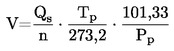
where:
|
— |
= |
V0 |
= |
pump flow rate at Tp and Pp given in m3/rev., |
|
— |
= |
Qs |
= |
air flow at 101,33 kPa and 273,2 K given in m3/min., |
|
— |
= |
Tp |
= |
pump inlet temperature (K), |
|
— |
= |
Pp |
= |
absolute pump inlet pressure (kPa), |
|
— |
= |
n |
= |
pump speed in min–1. |
To compensate for the interaction of pump speed pressure variations at the pump and the pump slip rate, the correlation function (x0) between the pump speed (n), the pressure differential from pump inlet to pump outlet and the absolute pump outlet pressure is then calculated as follows:

where:
|
— |
= |
x0 |
= |
correlation function, |
|
— |
= |
ΔPp |
= |
pressure differential from pump inlet to pump outlet (kPa), |
|
— |
= |
Pe |
= |
absolute outlet pressure (PPO + Pb) (kPa). |
A linear least-square fit is performed to generate the calibration equations which have the formulae:
V0 = D0 – M (x0)
n = A – B (ΔPp)
D0, M, A and B are the slope-intercept constants describing the lines.
Figure 6/2
PDP-CVS calibration configuration

Figure 6/3
CFV-CVS calibration configuration

4.2.4.3. A CVS system that has multiple speeds shall be calibrated on each speed used. The calibration curves generated for the ranges shall be approximately parallel and the intercept values (D0) shall increase as the pump flow range decreases.
If the calibration has been performed carefully, the calculated values from the equation will be within 0.5 per cent of the measured value of V0. Values of M will vary from one pump to another. Calibration is performed at pump start-up and after major maintenance.
Calibration of the critical-flow venturi (CFV)
4.3.1. Calibration of the CFV is based upon the flow equation for a critical venturi:
![]()
where:
|
— |
= |
Qs |
= |
flow, |
|
— |
= |
Kv |
= |
calibration coefficient, |
|
— |
= |
P |
= |
absolute pressure (kPa), |
|
— |
= |
T |
= |
absolute temperature (K). |
Gas flow is a function of inlet pressure and temperature.
The calibration procedure described below establishes the value of the calibration coefficient at measured values of pressure, temperature and air flow.
4.3.2. The manufacturer's recommended procedure shall be followed for calibrating electronic portions of the CFV.
4.3.3. Measurements for flow calibration of the critical flow venturi are required and the following data shall be found within the limits of precision given:
|
± 0,03 kPa, |
||
|
± 0,15 K, |
||
|
± 0,01 kPa, |
||
|
± 0,0015 kPa, |
||
|
± 0,5 per cent, |
||
|
± 0,02 kPa, |
||
|
± 0,2 K. |
4.3.4. The equipment shall be set up as shown in figure 3 of this Appendix and checked for leaks. Any leaks between the flow-measuring device and the critical-flow venturi will seriously affect the accuracy of the calibration.
4.3.5. The variable-flow restrictor shall be set to the open position, the blower shall be started and the system stabilised. Data from all instruments shall be recorded.
4.3.6. The flow restrictor shall be varied and at least eight readings across the critical flow range of the venturi shall be made.
4.3.7. The data recorded during the calibration shall be used in the following calculations.
The air flow-rate (Qs) at each test point is calculated from the flow-meter data using the manufacturer's prescribed method.
Calculate values of the calibration coefficient for each test point:

where:
|
— |
= |
Qs |
= |
flow-rate in m3/min at 273,2 K and 101,33 kPa, |
|
— |
= |
Tv |
= |
temperature at the venturi inlet (K), |
|
— |
= |
Pv |
= |
absolute pressure at the venturi inlet (kPa). |
Plot Kv as a function of venturi inlet pressure. For sonic flow, Kv will have a relatively constant value. As pressure decreases (vacuum increases) the venturi becomes unchoked and Kv decreases. The resultant Kv changes are not permissible.
For a minimum of eight points in the critical region, calculate an average Kv and the standard deviation.
If the standard deviation exceeds 0,3 per cent of the average Kv, take corrective action.
ANNEX 4
Appendix 7
TOTAL SYSTEM VERIFICATION
1. To comply with the requirements of paragraph 4.7 of Annex 4, the total accuracy of the CVS sampling system and analytical system shall be determined by introducing a known mass of a pollutant gas into the system whilst it is being operated as if during a normal test and then analysing and calculating the pollutant mass according to the formulae in Appendix 8 to Annex 4 except that the density of propane shall be taken as 1,967 grams per litre at standard conditions. The following two techniques are known to give sufficient accuracy.
2. Metering a constant flow of pure gas (CO or C3H8) using a critical flow orifice device
2.1. A known quantity of pure gas (CO or C3H8) is fed into the CVS system through the calibrated critical orifice. If the inlet pressure is high enough, the flow-rate (q), which is adjusted by means of the critical flow orifice, is independent of orifice outlet pressure (critical flow). If deviations exceeding 5 per cent occur, the cause of the malfunction shall be determined and corrected. The CVS system is operated as in an exhaust emission test for about 5 to 10 minutes. The gas collected in the sampling bag is analysed by the usual equipment and the results compared to the concentration of the gas samples which was known beforehand.
3. Metering a limited quantity of pure gas (CO or C3H8) by means of a gravimetric technique
3.1. The following gravimetric procedure may be used to verify the CVS system.
The weight of a small cylinder filled with either carbon monoxide or propane is determined with a precision of ± 0,01 g. For about 5 to 10 minutes, the CVS system is operated as in a normal exhaust emission test, while CO or propane is injected into the system. The quantity of pure gas involved is determined by means of differential weighing. The gas accumulated in the bag is then analysed by means of the equipment normally used for exhaust-gas analysis. The results are then compared to the concentration figures computed previously.
ANNEX 4
Appendix 8
CALCULATION OF THE MASS EMISSIONS OF POLLUTANTS
1. GENERAL PROVISIONS
1.1. Mass emissions of gaseous pollutants shall be calculated by means of the following equation:
 (1)
(1)
where:
|
— |
= |
Mi |
= |
mass emission of the pollutant i in grams per kilometer, |
|
— |
= |
Vmix |
= |
volume of the diluted exhaust gas expressed in litres per test and corrected to standard conditions (273,2 K and 101,33 kPa), |
|
— |
= |
Qi |
= |
density of the pollutant i in grams per litre at normal temperature and pressure (273,2 K and 101,33 kPa), |
|
— |
= |
kh |
= |
humidity correction factor used for the calculation of the mass emissions of oxides of nitrogen. There is no humidity correction for HC and CO, |
|
— |
= |
Ci |
= |
concentration of the pollutant i in the diluted exhaust gas expressed in ppm and corrected by the amount of the pollutant i contained in the dilution air, |
|
— |
= |
d |
= |
distance corresponding to the operating cycle in kilometres. |
1.2. Volume determination
1.2.1. Calculation of the volume when a variable dilution device with constant flow control by orifice or venturi is used
Record continuously the parameters showing the volumetric flow, and calculate the total volume for the duration of the test.
1.2.2. Calculation of volume when a positive displacement pump is used
The volume of diluted exhaust gas measured in systems comprising a positive displacement pump is calculated with the following formula:
V = V0 · N
where:
|
— |
= |
V |
= |
volume of the diluted gas expressed in litres per test (prior to correction), |
|
— |
= |
Vo |
= |
volume of gas delivered by the positive displacement pump in testing conditions in litres per revolution, |
|
— |
= |
N |
= |
number of revolutions per test. |
1.2.3. Correction of the diluted exhaust-gas volume to standard conditions
The diluted exhaust-gas volume is corrected by means of the following formula:
 (2)
(2)
in which:
![]() (3)
(3)
where:
|
— |
= |
PB |
= |
barometric pressure in the test room in kPa, |
|
— |
= |
P1 |
= |
vacuum at the inlet to the positive displacement pump in kPa relative to the ambient barometric pressure, |
|
— |
= |
Tp |
= |
average temperature of the diluted exhaust gas entering the positive displacement pump during the test (K). |
1.3. Calculation of the corrected concentration of pollutants in the sampling bag
 (4)
(4)
where:
|
— |
= |
Ci |
= |
concentration of the pollutant i in the diluted exhaust gas, expressed in ppm and corrected by the amount of i contained in the dilution air, |
|
— |
= |
Ce |
= |
measured concentration of pollutant i in the diluted exhaust gas, expressed in ppm, |
|
— |
= |
Cd |
= |
concentration of pollutant i in the air used for dilution, expressed in ppm, |
|
— |
= |
DF |
= |
dilution factor. |
The dilution factor is calculated as follows:
For petrol and diesel
|
DF = |
|
for petrol and diesel (5a) |
|
DF = |
|
for LPG (5b) |
|
DF = |
|
For NG (5c) |
In these equations:
|
— |
= |
CCO2 |
= |
concentration of CO2 in the diluted exhaust gas contained in the sampling bag, expressed in per cent volume, |
|
— |
= |
CHC |
= |
concentration of HC in the diluted exhaust gas contained in the sampling bag, expressed in ppm carbon equivalent, |
|
— |
= |
CCO |
= |
concentration of CO in the diluted exhaust gas contained in the sampling bag, expressed in ppm. |
1.4. Determination of the no humidity correction factor
In order to correct the influence of humidity on the results of oxides of nitrogen, the following calculations are applied:
![]() (6)
(6)
in which:
![]()
where:
|
— |
= |
H |
= |
absolute humidity expressed in grams of water per kilogram of dry air, |
|
— |
= |
Ra |
= |
relative humidity of the ambient air expressed as a percentage, |
|
— |
= |
Pd |
= |
saturation vapour pressure at ambient temperature expressed in kPa, |
|
— |
= |
PB |
= |
atmospheric pressure in the room, expressed in kPa. |
1.5. Example
1.5.1. Data
1.5.1.1. Ambient conditions:
|
— |
ambient temperature: 23 °C = 297,2 K, |
|
— |
barometric pressure: PB = 101,33 kPa, |
|
— |
relative humidity: Ra = 60 per cent, |
|
— |
saturation vapour pressure: Pd = 2,81 kPa of H2O at 23 °C. |
1.5.1.2. Volume measured and reduced to standard conditions (paragraph 1)
V = 51,961 m3
1.5.1.3. Analyser readings:
|
|
Diluted exhaust sample |
Dilution-air sample |
|
HC (24) |
92 ppm |
3,0 ppm |
|
CO |
470 ppm |
0 ppm |
|
NOx |
70 ppm |
0 ppm |
|
CO2 |
1,6 per cent by volume |
0,03 per cent by volume |
1.5.2. Calculations
1.5.2.1. Humidity correction factor (kH) (see formula 6)
![]()

H = 10,5092
![]()
![]()
kh = 0,9934
1.5.2.2. Dilution factor (DF) (see formula (5))


DF = 8,091
1.5.2.3. Calculation of the corrected concentration of pollutants in the sampling bag:
HC, mass emissions (see formulae (4) and (1))
|
Ci |
= |
Ce – Cd
|
|
Ci |
= |
92 – 3 (1-)
|
|
Ci |
= |
89,371 |
|
MHC |
= |
CHC · Vmix · QHC ·
|
|
QHC |
= |
0,619 in the case of petrol or diesel |
|
QHC |
= |
0,649 in the case of LPG |
|
QHC |
= |
0,714 in the case of NG |
|
MHC |
= |
89,371 · 51,961 · 0,619 · 10–6 ·
|
|
MHC |
= |
|
CO, mass emissions (see formula (1))
|
MCO |
= |
CCO · Vmix · QCO ·
|
|
QCO |
= |
1,25 |
|
MCO |
= |
470 · 51,961 · 1.25 · 10–6 ·
|
|
MCO |
= |
|
NOx mass emissions (see formula (1))
|
MNOx |
= |
CNOx
· Vmix · QNOx
· kH ·
|
|
QNOx |
= |
2,05 |
|
MNOx |
= |
70 · 51,961 · 2,05 · 0,9934 · 10–6 ·
|
|
MNOx |
= |
|
2. SPECIAL PROVISIONS FOR VEHICLES EQUIPPED WITH COMPRESSION-IGNITION ENGINES
2.1. Determination of HC for compression-ignition engines
To calculate HC-mass emission for compression-ignition engines, the average HC concentration is calculated as follows:
 (7)
(7)
where:
|
— |
= |
|
= |
integral of the recording of the heated FID over the test (t2 – t1) |
|
— |
= |
Ce |
= |
concentration of HC measured in the diluted exhaust in ppm of Ci is substituted for CHC in all relevant equations. |
2.2. Determination of particulates
Particulate emission Mp (g/km) is calculated by means of the following equation:

where exhaust gases are vented outside tunnel,

where exhaust gases are returned to the tunnel,
where:
|
Vmix |
= |
Volume of diluted exhaust gases (see paragraph 1.1), under standard conditions, |
|
Vep |
= |
Volume of exhaust gas flowing through particulate filter under standard conditions, |
|
Pe |
= |
Particulate mass collected by filters, |
|
d |
= |
Distance corresponding to the operating cycle in km, |
|
Mp |
= |
Particulate emission in g/km. |
ANNEX 5
TYPE II TEST
(Carbon monoxide emission test at idling speed)
1. INTRODUCTION
This annex describes the procedure for the Type II test defined in paragraph 5.3.2 of this Regulation.
2. CONDITIONS OF MEASUREMENT
2.1. The fuel shall be the reference fuel, specifications for which are given in Annexes 10 and 10a to this Regulation.
During the test, the environmental temperature shall be between 293 and 303 K (20 and 30 °C). The engine shall be warmed up until all temperatures of cooling and lubrication means and the pressure of lubrication means have reached equilibrium.
2.2.1. Vehicles that are fuelled either with petrol or with LPG or NG shall be tested with the reference fuel(s) used for the Type I test.
2.3. In the case of vehicles with manually-operated or semi-automatic-shift gearboxes, the test shall be carried out with the gear lever in the ‘neutral’ position and with the clutch engaged.
2.4. In the case of vehicles with automatic-shift gearboxes, the test shall be carried out with the gear selector in either the ‘neutral’ or the ‘parking’ position.
2.5. Components for adjusting the idling speed
2.5.1. Definition
For the purposes of this Regulation, ‘components for adjusting the idling speed’ means controls for changing the idling conditions of the engine which may be easily operated by a mechanic using only the tools described in paragraph 2.5.1.1 below. In particular, devices for calibrating fuel and air flows are not considered as adjustment components if their setting requires the removal of the set-stops, an operation which cannot normally be performed except by a professional mechanic.
2.5.1.1. Tools which may be used to control components for adjusting the idling speed: screwdrivers (ordinary or cross-headed), spanners (ring, open-end or adjustable), pliers, Allen keys.
2.5.2. Determination of measurement points
2.5.2.1. A measurement at the setting in accordance with the conditions fixed by the manufacturer is performed first;
2.5.2.2. For each adjustment component with a continuous variation, a sufficient number of characteristic positions shall be determined.
2.5.2.3. The measurement of the carbon-monoxide content of exhaust gases shall be carried out for all the possible positions of the adjustment components, but for components with a continuous variation only the positions defined in paragraph 2.5.2.2 above shall be adopted.
The Type II test shall be considered satisfactory if one or both of the two following conditions is met:
2.5.2.4.1. none of the values measured in accordance with paragraph 2.5.2.3 above exceeds the limit values;
2.5.2.4.2. the maximum content obtained by continuously varying one of the adjustment components while the other components are kept stable does not exceed the limit value, this condition being met for the various combinations of adjustment components other than the one which was varied continuously.
The possible positions of the adjustment components shall be limited:
2.5.2.5.1. on the one hand, by the larger of the following two values: the lowest idling speed which the engine can reach; the speed recommended by the manufacturer, minus 100 revolutions per minute;
2.5.2.5.2. on the other hand, by the smallest of the following three values:
the highest speed the engine can attain by activation of the idling speed components;
the speed recommended by the manufacturer, plus 250 revolutions per minute;
the cut-in speed of automatic clutches.
2.5.2.6. In addition, settings incompatible with correct running of the engine shall not be adopted as measurement settings. In particular, when the engine is equipped with several carburettors all the carburettors shall have the same setting.
3. SAMPLING OF GASES
3.1. The sampling probe shall be inserted into the exhaust pipe to a depth of at least 300 mm into the pipe connecting the exhaust with the sampling bag and as close as possible to the exhaust.
3.2. The concentration in CO (CCO) and CO2 (CCO2 ) shall be determined from the measuring instrument readings or recordings, by use of appropriate calibration curves.
3.3. The corrected concentration for carbon monoxide regarding four-stroke engines is:
 (per cent vol.)
3.4. The concentration in CCO (see paragraph 3.2) measured according to the formulae contained in paragraph 3.3 need not be corrected if the total of the concentrations measured (CCO + CCO2 ) is for four-stroke engines at least:
|
— |
for petrol: |
15 per cent, |
|
— |
for LPG: |
13,5 per cent, |
|
— |
for NG: |
11,5 per cent. |
ANNEX 6
TYPE III TEST
(Verifying emissions of crankcase gases)
1. INTRODUCTION
This annex describes the procedure for the Type III test defined in paragraph 5.3.3 of this Regulation.
2. GENERAL PROVISIONS
2.1. The Type III test shall be carried out on a vehicle with positive-ignition engine, which has been, subjected to the Type I and the Type II test, as applicable.
2.2. The engines tested shall include leak-proof engines other than those so designed that even a slight leak may cause unacceptable operating faults (such as flat-twin engines).
3. TEST CONDITIONS
3.1. Idling shall be regulated in conformity with the manufacturer's recommendations.
3.2. The measurement shall be performed in the following three sets of conditions of engine operation:
|
Condition Number |
Vehicle speed (km/h) |
|
1 |
Idling |
|
2 |
50 ± 2 (in 3rd gear or ‘drive’) |
|
3 |
50 ± 2 (in 3rd gear or ‘drive’) |
|
Condition Number |
Power absorbed by the brake |
|
1 |
Nil |
|
2 |
That corresponding to the setting for Type I test at 50 km/h |
|
3 |
That for conditions No 2, multiplied by a factor of 1,7 |
4. TEST METHOD
4.1. For the operation conditions as listed in paragraph 3.2 above, reliable function of the crankcase ventilation system shall be checked.
5. METHOD OF VERIFICATION OF THE CRANKCASE VENTILATION SYSTEM
5.1. The engine's apertures shall be left as found.
5.2. The pressure in the crankcase shall be measured at an appropriate location. It shall be measured at the dip-stick hole with an inclined-tube manometer.
5.3. The vehicle shall be deemed satisfactory if, in every condition of measurement defined in paragraph 3.2 above, the pressure measured in the crankcase does not exceed the atmospheric pressure prevailing at the time of measurement.
5.4. For the test by the method described above, the pressure in the intake manifold shall be measured to within ± 1 kPa.
5.5. The vehicle speed as indicated at the dynamometer shall be measured to within ± 2 km/h.
5.6. The pressure measured in the crankcase shall be measured to within ± 0,01 kPa.
5.7. If in one of the conditions of measurement defined in paragraph 3.2 above, the pressure measured in the crankcase exceeds the atmospheric pressure, an additional test as defined in paragraph 6 below shall be performed if so requested by the manufacturer.
6. ADDITIONAL TEST METHOD
6.1. The engine's apertures shall be left as found.
6.2. A flexible bag impervious to crankcase gases and having a capacity of approximately five litres shall be connected to the dipstick hole. The bag shall be empty before each measurement.
6.3. The bag shall be closed before each measurement. It shall be opened to the crankcase for five minutes for each condition of measurement prescribed in paragraph 3.2 above.
6.4. The vehicle shall be deemed satisfactory if, in every condition of measurement defined in paragraph 3.2 above, no visible inflation of the bag occurs.
6.5. Remark
6.5.1. If the structural layout of the engine is such that the test cannot be performed by the methods described in paragraphs 6.1 to 6.4 above, the measurements shall be effected by that method modified as follows:
6.5.2. Before the test, all apertures other than that required for the recovery of the gases shall be closed;
6.5.3. The bag shall be placed on a suitable take-off which does not introduce any additional loss of pressure and is installed on the recycling circuit of the device directly at the engine-connection aperture.
TYPE III TEST

ANNEX 7
TYPE IV TEST
(Determination of evaporative emissions from vehicles with positive-ignition engines)
1. INTRODUCTION
This annex describes the procedure of the Type IV test according to paragraph 5.3.4 of this Regulation.
This procedure describes a method for the determination of the loss of hydrocarbons by evaporation from the fuel systems of vehicles with positive-ignition engines.
2. DESCRIPTION OF TEST
The evaporative emissions test (Figure 7/1 below) is designed to determine hydrocarbon evaporative emissions as a consequence of diurnal temperatures fluctuation, hot soaks during parking, and urban driving. The test consists of these phases:
2.1. Test preparation including an urban (Part One) and extra-urban (Part Two) driving cycle,
2.2. Hot soak loss determination,
2.3. Diurnal loss determination.
Mass emissions of hydrocarbons from the hot soak and the diurnal loss phases are added up to provide an overall result for the test.
3. VEHICLE AND FUEL
3.1. Vehicle
3.1.1. The vehicle shall be in good mechanical condition and have been run in and driven at least 3 000 km before the test. The evaporative emission control system shall be connected and have been functioning correctly over this period and the carbon canister(s) shall have been subject to normal use, neither undergoing abnormal purging nor abnormal loading.
3.2. Fuel
3.2.1. The appropriate reference fuel shall be used, as defined in Annex 10 to this Regulation.
4. TEST EQUIPMENT FOR EVAPORATIVE TEST
4.1. Chassis dynamometer
The chassis dynamometer shall meet the requirements of Annex 4.
4.2. Evaporative emission measurement enclosure
The evaporative emission measurement enclosure shall be a gas-tight rectangular measuring chamber able to contain the vehicle under test. The vehicle shall be accessible from all sides and the enclosure when sealed shall be gas-tight in accordance with Appendix 1 to this annex. The inner surface of the enclosure shall be impermeable and non-reactive to hydrocarbons. The temperature conditioning system shall be capable of controlling the internal enclosure air temperature to follow the prescribed temperature versus time profile throughout the test, and an average tolerance of 1 K over the duration of the test.
The control system shall be tuned to provide a smooth temperature pattern that has a minimum of overshoot, hunting, and instability about the desired long-term ambient temperature profile. Interior surface temperatures shall not be less than 278 K (5 °C) nor more than 328 K (55 °C) at any time during the diurnal emission test.
Wall design shall be such as to promote good dissipation of heat. Interior surface temperatures shall not be below 293 K (20 °C), nor above 325 K (52 °C) for the duration of the hot soak rest.
To accommodate the volume changes due to enclosure temperature changes, either a variable-volume or fixed-volume enclosure may be used.
4.2.1. Variable-volume enclosure
The variable-volume enclosure expands and contracts in response to the temperature change of the air mass in the enclosure. Two potential means of accommodating the internal volume changes are movable panel(s), or a bellows design, in which an impermeable bag or bags inside the enclosure expand(s) and contracts(s) in response to internal pressure changes by exchanging air from outside the enclosure. Any design for volume accommodation shall maintain the integrity of the enclosure as specified in Appendix 1 to this annex over the specified temperature range.
Any method of volume accommodation shall limit the differential between the enclosure internal pressure and the barometric pressure to a maximum value of ± 5 KPa.
The enclosure shall be capable of latching to a fixed volume. A variable volume enclosure shall be capable of accommodating a +7 per cent change from its ’nominal volume’ (see Appendix 1 to this annex, paragraph 2.1.1), taking into account temperature and barometric pressure variation during testing.
4.2.2. Fixed-volume enclosure
The fixed-volume enclosure shall be constructed with rigid panels that maintain a fixed enclosure volume, and meet the requirements below.
4.2.2.1. The enclosure shall be equipped with an outlet flow stream that withdraws air at a low, constant rate from the enclosure throughout the test. An inlet flow stream may provide make-up air to balance the outgoing flow with incoming ambient air. Inlet air shall be filtered with activated carbon to provide a relatively constant hydrocarbon level. Any method of volume accommodation shall maintain the differential between the enclosure internal pressure and the barometric pressure between 0 and –5 kPa.
4.2.2.2. The equipment shall be capable of measuring the mass of hydrocarbon in the inlet and outlet flow streams with a resolution of 0,01 gram. A bag sampling system may be used to collect a proportional sample of the air withdrawn from and admitted to the enclosure. Alternatively, the inlet and outlet flow streams may be continuously analysed using an on-line FID analyser and integrated with the flow measurements to provide a continuous record of the mass hydrocarbon removal.
4.3. Analytical systems
4.3.1. Hydrocarbon analyser
4.3.1.1. The atmosphere within the chamber is monitored using a hydrocarbon detector of the flame ionisation detector (FID) type. Sample gas shall be drawn from the mid-point of one side wall or roof of the chamber and any bypass flow shall be returned to the enclosure, preferably to a point immediately downstream of the mixing fan.
4.3.1.2. The hydrocarbon analyser shall have a response time to 90 per cent of final reading of less than 1,5 seconds. Its stability shall be better than 2 per cent of full scale at zero and at 80 ± 20 per cent of full scale over a 15-minute period for all operational ranges.
4.3.1.3. The repeatability of the analyser expressed as one standard deviation shall be better than ± 1 per cent of full scale deflection at zero and at 80 ± 20 per cent of full scale on all ranges used.
Figure 7/1
Determination of evaporative emissions
3 000 km run-in period (no excessive purge/load)
Ageing of canister(s) verified
Steam-clean of vehicle (if necessary)

4.3.1.4. The operational ranges of the analyser shall be chosen to give best resolution over the measurement, calibration and leak checking procedures.
4.3.2. Hydrocarbon analyser data recording system
4.3.2.1. The hydrocarbon analyser shall be fitted with a device to record electrical signal output either by strip chart recorder or other data processing system at a frequency of at least once per minute. The recording system shall have operating characteristics at least equivalent to the signal being recorded and shall provide a permanent record of results. The record shall show a positive indication of the beginning and end of the hot soak or diurnal emission test (including beginning and end of sampling periods along with the time elapsed between start and completion of each test).
4.4. Fuel tank heating (only applicable for gasoline canister load option)
4.4.1. The fuel in the vehicle tank(s) shall be heated by a controllable source of heat; for example a heating pad of 2 000 W capacity is suitable. The heating system shall apply heat evenly to the tank walls beneath the level of the fuel so as not to cause local overheating of the fuel. Heat shall not be applied to the vapour in the tank above the fuel.
4.4.2. The tank heating device shall make it possible to heat the fuel in the tank evenly by 14 K from 289 K (16 °C) within 60 minutes, with the temperature sensor position as in paragraph 5.1.1 below. The heating system shall be capable of controlling the fuel temperature to ± 1,5 K of the required temperature during the tank heating process.
4.5. Temperature recording
4.5.1. The temperature in the chamber is recorded at two points by temperature sensors which are connected so as to show a mean value. The measuring points are extended approximately 0,1 m into the enclosure from the vertical centre line of each side wall at a height of 0,9 ± 0,2 m.
4.5.2. The temperatures of the fuel tank(s) are recorded by means of the sensor positioned in the fuel tank as in paragraph 5.1.1 below in the case of use of the gasoline canister load option (paragraph 5.1.5 below).
4.5.3. Temperatures shall, throughout the evaporative emission measurements, be recorded or entered into a data processing system at a frequency of at least once per minute.
4.5.4. The accuracy of the temperature recording system shall be within ± 1,0 K and the temperature shall be capable of being resolved to ± 0,4 K.
4.5.5. The recording or data processing system shall be capable of resolving time to ± 15 seconds.
4.6. Pressure recording
4.6.1. The difference Δp between barometric pressure within the test area and the enclosure internal pressure shall, throughout the evaporative emission measurements, be recorded or entered into a data processing system at a frequency of at least once per minute.
4.6.2. The accuracy of the pressure recording system shall be within ± 2 kPa and the pressure shall be capable of being resolved to ± 0,2 kPa.
4.6.3. The recording or data processing system shall be capable of resolving time to ± 15 seconds.
4.7. Fans
4.7.1. By the use of one or more fans or blowers with the SHED door(s) open it shall be possible to reduce the hydrocarbons concentration in the chamber to the ambient hydrocarbon level.
4.7.2. The chamber shall have one or more fans or blowers of like capacity 0,1 to 0,5 m3/min. with which to thoroughly mix the atmosphere in the enclosure. It shall be possible to attain an even temperature and hydrocarbon concentration in the chamber during measurements. The vehicle in the enclosure shall not be subjected to a direct stream of air from the fans or blowers.
4.8. Gases
4.8.1. The following pure gases shall be available for calibration and operation:
|
— |
Purified synthetic air: (purity < 1 ppm C1 equivalent, ≤ 1 ppm CO, ≤ 400 ppm CO2, ≤ 0,1 ppm NO); oxygen content between 18 and 21 per cent by volume. |
|
— |
Hydrocarbon analyser fuel gas: (40 ± 2 per cent hydrogen, and balance helium with less than 1 ppm C1 equivalent hydrocarbon, less than 400 ppm CO2), |
|
— |
Propane (C3H8): 99.5 per cent minimum purity. |
|
— |
Butane (C4H10): 98 per cent minimum purity, |
|
— |
Nitrogen (N2): 98 per cent minimum purity. |
4.8.2. Calibration and span gases shall be available containing mixtures of propane (C3H8) and purified synthetic air. The true concentrations of a calibration gas shall be within 2 per cent of the stated figures. The accuracy of the diluted gases obtained when using a gas divider shall be to within ± 2 per cent of the true value. The concentrations specified in Appendix 1 may also be obtained by the use of a gas divider using synthetic air as the dilutant gas.
4.9. Additional equipment
4.9.1. The absolute humidity in the test area shall be measurable to within ± 5 per cent.
5. TEST PROCEDURE
5.1. Test preparation
5.1.1. The vehicle is mechanically prepared before the test as follows:
|
(a) |
the exhaust system of the vehicle shall not exhibit any leaks, |
|
(b) |
the vehicle may be steam-cleaned before the test, |
|
(c) |
In the case of use of the gasoline canister load option (paragraph 5.1.5 below) the fuel tank of the vehicle shall be equipped with a temperature sensor to enable the temperature to be measured at the mid-point of the fuel in the fuel tank when filled to 40 per cent of its capacity, |
|
(d) |
additional fittings, adapters of devices may be fitted to the fuel system in order to allow a complete draining of the fuel tank. For this purpose it is not necessary to modify the shell of the tank. |
|
(e) |
The manufacturer may propose a test method in order to take into account the loss of hydrocarbons by evaporation coming only from the fuel system of the vehicle. |
5.1.2. The vehicle is taken into the test area where the ambient temperature is between 293 and 303 K (20 and 30 °C).
5.1.3. The ageing of the canister(s) has to be verified. This may be done by demonstrating that it has accumulated a minimum of 3 000 km. If this demonstration is not given, the following procedure is used. In the case of a multiple canister system each canister shall undergo the procedure separately.
5.1.3.1. The canister is removed from the vehicle. Special care shall be taken during this step to avoid damage to components and the integrity of the fuel system.
5.1.3.2. The weight of the canister shall be checked.
5.1.3.3. The canister is connected to a fuel tank, possibly an external one, filled with reference fuel, to 40 per cent volume of the fuel tank(s).
5.1.3.4. The fuel temperature in the fuel tank shall be between 183 K and 287 K (10 and 14 °C).
5.1.3.5. The (external) fuel tank is heated from 288 K to 318 K (15 to 45 °C) (1 °C increase every 9 minutes).
5.1.3.6. If the canister reaches breakthrough before the temperature reaches 318 K (45 °C), the heat source shall be turned off. Then the canister is weighed. If the canister did not reach breakthrough during the heating to 318 K (45 °C), the procedure from paragraph 5.1.3.3 above shall be repeated until breakthrough occurs.
5.1.3.7. Breakthrough may be checked as described in paragraphs 5.1.5 and 5.1.6 of this annex, or with the use of another sampling and analytical arrangement capable of detecting the emission of hydrocarbons from the canister at breakthrough.
5.1.3.8. The canister shall be purged with 25 ± 5 litres per minute with the emission laboratory air until 300 bed volume exchanges are reached.
5.1.3.9. The weight of the canister shall be checked.
5.1.3.10. The steps of the procedure in paragraphs 5.1.3.4 to 5.1.3.9 shall be repeated nine times. The test may be terminated prior to that, after not less than three ageing cycles, if the weight of the canister after the last cycles has stabilised.
5.1.3.11. The evaporative emission canister is reconnected and the vehicle restored to its normal operating condition.
5.1.4. One of the methods specified in paragraphs 5.1.5 and 5.1.6 shall be used to precondition the evaporative canister. For vehicles with multiple canisters, each canister shall be preconditioned separately.
5.1.4.1. Canister emissions are measured to determine breakthrough.
Breakthrough is here defined as the point at which the cumulative quantity of hydrocarbons emitted is equal to 2 grams.
5.1.4.2. Breakthrough may be verified using the evaporative emission enclosure as described in paragraphs 5.1.5 and 5.1.6 respectively. Alternatively, breakthrough may be determined using an auxiliary evaporative canister connected downstream of the vehicle's canister. The auxiliary canister shall be well purged with dry air prior to loading.
5.1.4.3. The measuring chamber shall be purged for several minutes immediately before the test until a stable background is obtained. The chamber air mixing fan(s) shall be switched on at this time.
The hydrocarbon analyser shall be zeroed and spanned immediately before the test.
5.1.5. Canister loading with repeated heat builds to breakthrough
5.1.5.1. The fuel tank(s) of the vehicle(s) is (are) emptied using the fuel tank drain(s). This shall be done so as not to abnormally purge or abnormally load the evaporative control devices fitted to the vehicle. Removal of the fuel cap is normally sufficient to achieve this.
5.1.5.2. The fuel tank(s) is (are) refilled with test fuel at a temperature of between 283 K to 287 K (10 to 14 °C) to 40 ± 2 per cent of the tank's normal volumetric capacity. The fuel cap(s) of the vehicle shall be fitted at this point.
5.1.5.3. Within one hour of being refuelled the vehicle shall be placed, with the engine shut off, in the evaporative emission enclosure. The fuel tank temperature sensor is connected to the temperature recording system. A heat source shall be properly positioned with respect to the fuel tank(s) and connected to the temperature controller. The heat source is specified in paragraph 4.4 above. In the case of vehicles fitted with more than one fuel tank, all the tanks shall be heated in the same way as described below. The temperatures of the tanks shall be identical to within ± 1,5 K.
5.1.5.4. The fuel may be artificially heated to the starting diurnal temperature of 293 K (20 °C) ± 1 K.
5.1.5.5. When the fuel temperature reaches at least 292 K (19 °C), the following steps shall be taken immediately: the purge blower shall be turned off; enclosure doors closed and sealed; and measurement initiated of the hydrocarbon level in the enclosure.
5.1.5.6. When the fuel temperature of the fuel tank reaches 293 K (20 °C) a linear heat build of 15 K (15 °C) begins. The fuel shall be heated in such a way that the temperature of the fuel during the heating conforms to the function below to within ± 1,5 K. The elapsed time of the heat build and temperature rise is recorded.
Tr = To + 0,2333 · t
where:
|
Tr |
= |
required temperature (K), |
|
To |
= |
initial temperature (K), |
|
t |
= |
time from start of the tank heat build in minutes. |
5.1.5.7. As soon as break-through occurs or when the fuel temperature reaches 308 K (35 °C), whichever occurs first, the heat source is turned off, the enclosure doors unsealed and opened, and the vehicle fuel tank cap(s) removed. If break-through has not occurred by the time the fuel temperature 308 K (35 °C), the heat source is removed from the vehicle, the vehicle removed from the evaporative emission enclosure and the entire procedure outlined in paragraph 5.1.7 below repeated until break-through occurs.
5.1.6. Butane loading to breakthrough
5.1.6.1. If the enclosure is used for the determination of the break-through (see paragraph 5.1.4.2 above) the vehicle shall be placed, with the engine shut off, in the evaporative emission enclosure.
5.1.6.2. The evaporative emission canister shall be prepared for the canister loading operation. The canister shall not be removed from the vehicle, unless access to it in its normal location is so restricted that loading can only reasonably be accomplished by removing the canister from the vehicle. Special care shall be taken during this step to avoid damage to the components and the integrity of the fuel system.
5.1.6.3. The canister is loaded with a mixture composed of 50 per cent butane and 50 per cent nitrogen by volume at a rate of 40 grams butane per hour.
5.1.6.4. As soon as the canister reaches breakthrough, the vapour source shall be shut off.
5.1.6.5. The evaporative emission canister shall then be reconnected and the vehicle restored to its normal operating condition.
5.1.7. Fuel drain and refill
5.1.7.1. The fuel tank(s) of the vehicle(s) is (are) emptied using the fuel tank drain(s). This shall be done so as not to abnormally purge or abnormally load the evaporative control devices fitted to the vehicle. Removal of the fuel cap is normally sufficient to achieve this.
5.1.7.2. The fuel tank(s) is (are) refilled with test fuel at a temperature of between 291 ± 8 K (18 ± 8 °C) to 40 + 2 per cent of the tank's normal volumetric capacity. The fuel cap(s) of the vehicle shall be fitted at this point.
5.2. Preconditioning drive
5.2.1. Within one hour from the completing of canister loading in accordance with paragraphs 5.1.5 or 5.1.6 the vehicle is placed on the chassis dynamometer and driven through one Part One and two Part Two driving cycles of Type I test as specified in Annex 4. Exhaust emissions are not sampled during this operation.
5.3. Soak
5.3.1. Within five minutes of completing the preconditioning operation specified in paragraph 5.2.1 above the engine bonnet shall be completely closed and the vehicle driven off the chassis dynamometer and parked in the soak area. The vehicle is parked for a minimum of 12 hours and a maximum of 36 hours. The engine oil and coolant temperatures shall have reached the temperature of the area or within ± 3 K of it at the end of the period.
5.4. Dynamometer test
5.4.1. After conclusion of the soak period the vehicle is driven through a complete Type I test drive as described in Annex 4 (cold start urban and extra urban test). Then the engine is shut off. Exhaust emissions may be sampled during this operation but the results shall not be used for the purpose of exhaust emission type approval.
5.4.2. Within two minutes of completing the Type I test drive specified in paragraph 5.4.1 above the vehicle is driven a further conditioning drive consisting of one urban test cycle (hot start) of a Type I test. Then the engine is shut off again. Exhaust emissions need not be sampled during this operation.
5.5. Hot soak evaporative emissions test
5.5.1. Before the completion of the test run the measuring chamber shall be purged for several minutes until a stable hydrocarbon background is obtained. The enclosure mixing fan(s) shall also be turned on at this time.
5.5.2. The hydrocarbon analyser shall be zeroed and spanned immediately prior to the test.
5.5.3. At the end of the driving cycle the engine bonnet shall be completely closed and all connections between the vehicle and the test stand disconnected. The vehicle is then driven to the measuring chamber with a minimum use of the accelerator pedal. The engine shall be turned off before any part of the vehicle enters the measuring chamber. The time at which the engine is switched off is recorded on the evaporative emission measurement data recording system and temperature recording begins. The vehicle's windows and luggage compartments shall be opened at this stage, if not already opened.
5.5.4. The vehicle shall be pushed or otherwise moved into the measuring chamber with the engine switched off.
5.5.5. The enclosure doors are closed and sealed gas-tight within two minutes of the engine being switched off and within seven minutes of the end of the conditioning drive.
5.5.6. The start of a 60 ± 0,5 minute hot soak period begins when the chamber is sealed. The hydrocarbon concentration, temperature and barometric pressure are measured to give the initial readings CHCi, Pi and Ti for the hot soak test. These figures are used in the evaporative emission calculation, paragraph 6. below. The ambient temperature T of the enclosure shall not be less than 296 K and no more than 304 K during the 60-minute hot soak period.
5.5.7. The hydrocarbon analyser shall be zeroed and spanned immediately before the end of the 60 ± 0,5 minute test period.
5.5.8. At the end of the 60 ± 0,5 minute test period, the hydrocarbon concentration in the chamber shall be measured. The temperature and the barometric pressure are also measured. These are the final readings CHCf, Pf and Tf for the hot soak test used for the calculation in paragraph 6 below.
5.6. Soak
5.6.1. The test vehicle shall be pushed or otherwise moved to the soak area without use of the engine and soaked for not less than 6 hours and not more than 36 hours between the end of the hot soak test and the start of the diurnal emission test. For at least 6 hours of this period the vehicle shall be soaked at 293 ± 2 K (20 ± 2 °C).
5.7. Diurnal test
5.7.1. The test vehicle shall be exposed to one cycle of ambient temperature according to the profile specified in Appendix 2 to this annex with a maximum deviation of ± 2 K at any time. The average temperature deviation from the profile, calculated using the absolute value of each measured deviation, shall not exceed ± 1 K. Ambient temperature shall be measured at least every minute. Temperature cycling begins when time Tstart = 0, as specified in paragraph 5.7.6 below.
5.7.2. The measuring chamber shall be purged for several minutes immediately before the test until a stable background is obtainable. The chamber mixing fan(s) shall also be switched on at this time.
5.7.3. The test vehicle, with the engine shut off and the test vehicle windows and luggage compartment(s) opened shall be moved into the measuring chamber. The mixing fan(s) shall be adjusted in such a way as to maintain a minimum air circulation speed of 8 km/h under the fuel tank of the test vehicle.
5.7.4. The hydrocarbon analyser shall be zeroed and spanned immediately before the test.
5.7.5. The enclosure doors shall be closed and gas-tight sealed.
5.7.6. Within 10 minutes of closing and sealing the doors, the hydrocarbon concentration, temperature and barometric pressure are measured to give the initial readings CHCi, Pi and Ti for the diurnal test. This is the point where time Tstart = 0.
5.7.7. The hydrocarbon analyser shall be zeroed and spanned immediately before the end of the test.
5.7.8. The end of the emission sampling period occurs 24 hours ± 6 minutes after the beginning of the initial sampling, as specified in paragraph 5.7.6 above. The time elapsed is recorded. The hydrocarbon concentration, temperature and barometric pressure are measured to give the final readings CHCf, Pf and Tf for the diurnal test used for the calculation in paragraph 6. This completes the evaporative emission test procedure.
6. CALCULATION
6.1. The evaporative emission tests described in paragraph 5 allow the hydrocarbon emissions from the diurnal and hot soak phases to be calculated. Evaporative losses from each of theses phases is calculated using the initial and final hydrocarbon concentrations, temperatures and pressures in the enclosure, together with the net enclosure volume. The formula below is used:

where:
|
— |
= |
MHC |
= |
hydrocarbon mass in grams, |
|
— |
= |
MHC,out |
= |
mass of hydrocarbon exiting the enclosure, in the case of fixed-volume enclosures for diurnal emission testing (grams), |
|
— |
= |
MHC,i |
= |
mass of hydrocarbon entering the enclosure, in the case of fixed-volume enclosures for diurnal emission testing (grams), |
|
— |
= |
CHC |
= |
measured hydrocarbon concentration in the enclosure (ppm volume in C1 equivalent), |
|
— |
= |
V |
= |
net enclosure volume in cubic metres corrected for the volume of the vehicle, with the windows and the luggage compartment open. If the volume of the vehicle is not determined a volume of 1,42 m3 is subtracted, |
|
— |
= |
T |
= |
ambient chamber temperature, in K, |
|
— |
= |
P |
= |
barometric pressure in kPa, |
|
— |
= |
H/C |
= |
hydrogen to carbon ratio, |
|
— |
= |
k |
= |
1,2 · (12 + H/C); |
where:
|
— |
= |
i |
= |
is the initial reading, |
|
— |
= |
f |
= |
is the final reading, |
|
— |
= |
H/C |
= |
is taken to be 2,33 for diurnal test losses, |
|
— |
= |
H/C |
= |
is taken to be 2,20 for hot soak losses. |
6.2. Overall results of test
The overall hydrocarbon mass emission for the vehicle is taken to be:
Mtotal = MDI + MHS
where:
|
— |
= |
Mtotal |
= |
overall mass emissions of the vehicle (grams), |
|
— |
= |
MDI |
= |
hydrocarbon mass emission for diurnal test (grams), |
|
— |
= |
MHS |
= |
hydrocarbon mass emission for the hot soak (grams). |
7. CONFORMITY OF PRODUCTION
7.1. For routine end-of-production-line testing, the holder of the approval may demonstrate compliance by sampling vehicles which shall meet the following requirements.
7.2. Test for leakage
7.2.1. Vents to the atmosphere from the emission control system shall be isolated.
7.2.2. A pressure of 370 ± 10 mm of H2O shall be applied to the fuel system.
7.2.3. The pressure shall be allowed to stabilise prior to isolating the fuel system from the pressure source.
7.2.4. Following isolation of the fuel system, the pressure shall not drop by more than 50 mm of H2O in five minutes.
7.3. Test for venting
7.3.1. Vents to the atmosphere from the emission control shall be isolated.
7.3.2. A pressure of 370 ± 10 mm of H2O shall be applied to the fuel system.
7.3.3. The pressure shall be allowed to stabilise prior to isolating the fuel system from the pressure source.
7.3.4. The venting outlets from the emission control systems to the atmosphere shall be reinstated to the production condition.
7.3.5. The pressure of the fuel system shall drop to below 100 mm of H2O in not less than 30 seconds but within two minutes.
7.3.6. At the request of the manufacturer the functional capacity for venting can be demonstrated by equivalent alternative procedure. The specific procedure should be demonstrated by the manufacturer to the technical service during the type approval procedure.
7.4. Purge test
7.4.1. Equipment capable of detecting an airflow rate of 1,0 litres in one minute shall be attached to the purge inlet and a pressure vessel of sufficient size to have negligible effect on the purge system shall be connected via a switching valve to the purge inlet, or alternatively.
7.4.2. The manufacturer may use a flow meter of his own choosing, if acceptable to the competent authority.
7.4.3. The vehicle shall be operated in such a manner that any design feature of the purge system that could restrict purge operation is detected and the circumstances noted.
7.4.4. Whilst the engine is operating within the bounds noted in paragraph 7.4.3 above, the air flow shall be determined by either:
7.4.4.1. The device indicated in paragraph 7.4.1 above being switched in. A pressure drop from atmospheric to a level indicating that a volume of 1,0 litres of air has flowed into the evaporative emission control system within one minute shall be observed; or
7.4.4.2. if an alternative flow measuring device is used, a reading of no less than 1,0 litre per minute shall be detectable.
7.4.4.3. At the request of the manufacturer an alternative purge tat procedure can be used, if the procedure has been presented to and has been accepted by the technical service during the type approval procedure.
7.5. The competent authority which has granted type approval may at any time verify the conformity control methods applicable to each production unit.
7.5.1. The inspector shall take a sufficiently large sample from the series.
7.5.2. The inspector may test these vehicles by application of paragraph 8.2.5 of this Regulation.
7.6. If the requirements of paragraph 7.5 above are not met, the competent authority shall ensure that all necessary steps are taken to re-establish conformity of production as rapidly as possible.
ANNEX 7
Appendix 1
CALIBRATION OF EQUIPMENT FOR EVAPORATIVE EMISSION TESTING
1. CALIBRATION FREQUENCY AND METHODS
1.1. All equipment shall be calibrated before its initial use and then calibrated as often as necessary and in any case in the month before type approval testing. The calibration methods to be used are described in this Appendix.
1.2. Normally the series of temperatures which are mentioned first shall be used. The series of temperatures within square brackets may alternatively be used.
2. CALIBRATION OF THE ENCLOSURE
2.1. Initial determination of internal volume of the enclosure
2.1.1. Before its initial use, the internal volume of the chamber shall be determined as follows:
The internal dimensions of the chamber are carefully measured, allowing for any irregularities such as bracing struts. The internal volume of the chamber is determined from these measurements.
For variable-volume enclosures, the enclosure shall be latched to a fixed volume when the enclosure is held at an ambient temperature of 303 K (30 °C) [302 K (29 °C)]. This nominal volume shall be repeatable within ± 0,5 per cent of the reported value.
2.1.2. The net internal volume is determined by subtracting 1,42 m3 from the internal volume of the chamber. Alternatively the volume of the test vehicle with the luggage compartment and windows open may be used instead of the 1,42 m3.
2.1.3. The chamber shall be checked as in paragraph 2.3 below. If the propane mass does not correspond to the injected mass to within ± 2 per cent, then corrective action is required.
2.2. Determination of chamber background emissions
This operation determines that the chamber does not contain any materials that emit significant amounts of hydrocarbons. The check shall be carried out at the enclosure's introduction to service, after any operations in the enclosure which may affect background emissions and at a frequency of at least once per year.
2.2.1. Variable-volume enclosures may be operated in either latched or unlatched volume configuration, as described in paragraph 2.1.1 above, ambient temperatures shall be maintained at 308 K ± 2 K (35 ± 2 °C) [309 K ± 2 K (36 ± 2 °C)], throughout the 4-hour period mentioned below.
2.2.2. Fixed volume enclosures shall be operated with the inlet and outlet flow streams closed. Ambient temperatures shall be maintained at 308 K ± 2 K (35 ± 2 °C) [309 K ± 2 K (36 ± 2 °C)] throughout the 4-hour period mentioned below.
2.2.3. The enclosure may be sealed and the mixing fan operated for a period of up to 12 hours before the 4-hour background sampling period begins.
2.2.4. The analyser (if required) shall be calibrated, then zeroed and spanned.
2.2.5. The enclosure shall be purged until a stable hydrocarbon reading is obtained, and the mixing fan turned on if not already on.
2.2.6. The chamber is then sealed and the background hydrocarbon concentration, temperature and barometric pressure are measured. These are the initial readings CHCi, Pi, Ti used in the enclosure background calculation.
2.2.7. The enclosure is allowed to stand undisturbed with the mixing fan on for a period of four hours.
2.2.8. At the end of this time the same analyser is used to measure the hydrocarbon concentration in the chamber. The temperature and the barometric pressure are also measured. These are the final readings CHCf, Pf, Tf.
2.2.9. The change in mass of hydrocarbons in the enclosure shall be calculated over the time of the test in accordance with paragraph 2.4 below and shall not exceed 0,05 g.
2.3. Calibration and hydrocarbon retention test of the chamber
The calibration and hydrocarbon retention test in the chamber provides a check on the calculated volume in paragraph 2.1. above and also measures any leak rate. The enclosure leak rate shall be determined at the enclosure's introduction to service, after any operations in the enclosure which may affect the integrity of the enclosure, and at least monthly thereafter. If six consecutive monthly retention checks are successfully completed without corrective action, the enclosure leak rate may be determined quarterly thereafter as long as no corrective action is required.
2.3.1. The enclosure shall be purged until a stable hydrocarbon concentration is reached. The mixing fan is turned on, if not already switched on. The hydrocarbon analyser is zeroed, calibrated if required, and spanned.
2.3.2. On variable-volume enclosures, the enclosure shall be latched to the nominal volume position. On fixed-volume enclosures the outlet and inlet flow streams shall be closed.
2.3.3. The ambient temperature control system is then turned on (if not already on) and adjusted for an initial temperature of 308 K (35 °C) [309 K (36 °C)].
2.3.4. When the enclosure stabilises at 308 K ± 2 K (35 ± 2 °C) [309 K ± 2 K (36 ± 2 °C)], the enclosure is sealed and the background concentration, temperature and barometric pressure measured. These are the initial readings CHCi, Pi, Ti used in the enclosure calibration.
2.3.5. A quantity of approximately 4 grams of propane is injected into the enclosure. The mass of propane shall be measured to an accuracy and precision of ± 2 per cent of the measured value.
2.3.6. The contents of the chamber shall be allowed to mix for five minutes and then the hydrocarbon concentration, temperature and barometric pressure are measured. These are the readings CHCf, Pf, Tf for the calibration of the enclosure as well as the initial readings CHCi, Pi, Ti for the retention check.
2.3.7. Based on the readings taken according to paragraphs 2.3.4 and 2.3.6 above and the formula in paragraph 2.4 below, the mass of propane in the enclosure is calculated. This shall be within ± 2 per cent of the mass of propane measured in paragraph 2.3.5 above.
2.3.8. For variable-volume enclosures the enclosure shall be unlatched from the nominal volume configuration. For fixed-volume enclosures, the outlet and inlet flow streams shall be opened.
2.3.9. The process is then begun of cycling the ambient temperature from 308 K (35 °C) to 293 K (20 °C) and back to 308 K (35 °C) [308,6 K (35,6 °C) to 295,2 K (22,2 °C) and back to 308,6 K (35,6 °C)] over a 24-hour period according to the profile [alternative profile] specified in Appendix 2 to this annex within 15 minutes of sealing the enclosure. (Tolerances as specified in paragraph 5.7.1 of Annex 7).
2.3.10. At the completion of the 24-hour cycling period, the final hydrocarbon concentration, temperature and barometric pressure are measured and recorded. These are the final readings CHCf, Pf, Tf for the hydrocarbon retention check.
2.3.11. Using the formula in paragraph 2.4 below, the hydrocarbon mass is then calculated from the readings taken in paragraphs 2.3.10 and 2.3.6 above. The mass may not differ by more than 3 per cent from the hydrocarbon mass given in paragraph 2.3.7 above.
2.4. Calculations
The calculation of net hydrocarbon mass change within the enclosure is used to determine the chamber's hydrocarbon background and leak rate. Initial and final readings of hydrocarbon concentration, temperature and barometric pressure are used in the following formula to calculate the mass change.

where:
|
— |
= |
MHC |
= |
hydrocarbon mass in grams, |
|
— |
= |
MHC,out |
= |
mass of hydrocarbons exiting the enclosure, in the case of fixed-volume enclosures for diurnal emission testing (grams), |
|
— |
= |
MHC,i |
= |
mass of hydrocarbons entering the enclosure when a fixed-volume enclosure is used for testing diurnal emissions (grams), |
|
— |
= |
CHC |
= |
hydrocarbon concentration in the enclosure (ppm carbon (Note: ppm carbon = ppm propane x 3)), |
|
— |
= |
V |
= |
enclosure volume in cubic metres, |
|
— |
= |
T |
= |
ambient temperature in the enclosure, (K), |
|
— |
= |
P |
= |
barometric pressure, (kPa), |
|
— |
= |
k |
= |
17,6; |
where:
|
— |
i |
is the initial reading, |
|
— |
f |
is the final reading. |
3. CHECKING OF FID HYDROCARBON ANALYZER
3.1. Detector response optimisation
The FID shall be adjusted as specified by the instrument manufacturer. Propane in air should be used to optimise the response on the most common operating range.
3.2. Calibration of the HC analyser
The analyser should be calibrated using propane in air and purified synthetic air. See paragraph 4.5.2 of Annex 4 (Calibration and span gases).
Establish a calibration curve as described in paragraphs 4.1 to 4.5 of this appendix.
3.3. Oxygen interference check and recommended limits
The response factor (Rf) for a particular hydrocarbon species is the ratio of the FID C1 reading to the gas cylinder concentration, expressed as ppm C1. The concentration of the test gas shall be at a level to give a response of approximately 80 per cent of full-scale deflection, for the operating range. The concentration shall be known, to an accuracy of ± 2 per cent in reference to a gravimetric standard expressed in volume. In addition the gas cylinder shall be preconditioned for 24 hours at a temperature between 293 K and 303 K (20 and 30 °C).
Response factors should be determined when introducing an analyser into service and thereafter at major service intervals. The reference gas to be used is propane with balance purified air which is taken to give a response factor of 1,00.
The test gas to be used for oxygen interference and the recommended response factor range are given below:
Propane and nitrogen: 0,95 ≤ Rf ≤ 1,05.
4. CALIBRATION OF THE HYDROCARBON ANALYZER
Each of the normally used operating ranges are calibrated by the following procedure:
4.1. Establish the calibration curve by at least five calibration points spaced as evenly as possible over the operating range. The nominal concentration of the calibration gas with the highest concentrations to be at least 80 per cent of the full scale.
4.2. Calculate the calibration curve by the method of least squares. If the resulting polynomial degree is greater than 3, then the number of calibration points shall be at least the number of the polynomial degree plus 2.
4.3. The calibration curve shall not differ by more than 2 per cent from the nominal value of each calibration gas.
4.4. Using the coefficients of the polynomial derived from paragraph 3.2 above, a table of indicated reading against true concentration shall be drawn up in steps of no greater than 1 per cent of full scale. This is to be carried out for each analyser range calibrated. The table shall also contain other relevant data such as:
|
(a) |
date of calibration, span and zero potentiometer readings (where applicable), |
|
(b) |
nominal scale, |
|
(c) |
reference data of each calibration gas used, |
|
(d) |
the actual and indicated value of each calibration gas used together with the percentage differences, |
|
(e) |
FID fuel and type, |
|
(f) |
FID air pressure. |
4.5. If it can be shown to the satisfaction of the technical service that alternative technology (e.g. computer, electronically controlled range switch) can give equivalent accuracy, then those alternatives may be used.
ANNEX 7
Appendix 2
|
Diurnal ambient temperature profile for the calibration of the enclosure and the diurnal emission test |
Alternative diurnal ambient temperature profile for the calibration of the enclosure in accordance with Annex 7, Appendix 1, paragraphs 1.2 and 2.3.9 |
|||
|
Time (hours) |
Temperature (°Ci) |
Time (hours) |
Temperature (°Ci) |
|
|
Calibration |
Test |
|||
|
13 |
0/24 |
20,0 |
0 |
35,6 |
|
14 |
1 |
20,2 |
1 |
35,3 |
|
15 |
2 |
20,5 |
2 |
34,5 |
|
16 |
3 |
21,2 |
3 |
33,2 |
|
17 |
4 |
23,1 |
4 |
31,4 |
|
18 |
5 |
25,1 |
5 |
29,7 |
|
19 |
6 |
27,2 |
6 |
28,2 |
|
20 |
7 |
29,8 |
7 |
27,2 |
|
21 |
8 |
31,8 |
8 |
26,1 |
|
22 |
9 |
33,3 |
9 |
25,1 |
|
23 |
10 |
34,4 |
10 |
24,3 |
|
24/0 |
11 |
35,0 |
11 |
23,7 |
|
1 |
12 |
34,7 |
12 |
23,3 |
|
2 |
13 |
33,8 |
13 |
22,9 |
|
3 |
14 |
32,0 |
14 |
22,6 |
|
4 |
15 |
30,0 |
15 |
22,2 |
|
5 |
16 |
28,4 |
16 |
22,5 |
|
6 |
17 |
26,9 |
17 |
24,2 |
|
7 |
18 |
25,2 |
18 |
26,8 |
|
8 |
19 |
24,0 |
19 |
29,6 |
|
9 |
20 |
23,0 |
20 |
31,9 |
|
10 |
21 |
22,0 |
21 |
33,9 |
|
11 |
22 |
20,8 |
22 |
35,1 |
|
12 |
23 |
20,2 |
23 |
35,4 |
|
|
|
|
24 |
35,6 |
ANNEX 8
TYPE VI TEST
(Verifying the average exhaust emissions of carbon monoxide and hydrocarbons after a cold start at low ambient temperature)
1. INTRODUCTION
This annex applies only to vehicles with positive-ignition engines. It describes the equipment required and the procedure for the Type VI test defined in paragraph 5.3.5 of this Regulation in order to verify the emissions of carbon monoxide and hydrocarbons at low ambient temperatures. Topics addressed in this Regulation include:
|
(i) |
Equipment requirements; |
|
(ii) |
Test conditions; |
|
(iii) |
Test procedures and data requirements. |
2. TEST EQUIPMENT
2.1. Summary
2.1.1. This chapter deals with the equipment needed for low ambient temperature exhaust emission tests of positive-ignition engined vehicles. Equipment required and specifications are equivalent to the requirements for the Type I test as specified in Annex 4, with appendices, if specific requirements for the Type VI test are not prescribed. Paragraphs 2.2 to 2.6 describe deviations applicable to Type VI low ambient temperature testing.
2.2. Chassis dynamometer
2.2.1. The requirements of paragraph 4.1 of Annex 4 apply. The dynamometer shall be adjusted to simulate the operation of a vehicle on the road at 266 K (–7 °C). Such adjustment may be based on a determination of the road load force profile at 266 K (–7 °C). Alternatively the driving resistance determined according to Appendix 3 of Annex 4 may be adjusted for a 10 per cent decrease of the coast-down time. The technical service may approve the use of other methods of determining the driving resistance.
2.2.2. For calibration of the dynamometer the provisions of Appendix 2 to Annex 4 apply.
2.3. Sampling system
2.3.1. The provisions of paragraph 4.2 of Annex 4 and Appendix 5 to Annex 4 apply. Paragraph 2.3.2 of Appendix 5 is modified to read:
‘The piping configuration, flow capacity of the CVS, and the temperature and specific humidity of the dilution air (which may be different from the vehicle combustion air source) shall be controlled so as to virtually eliminate water condensation in the system (a flow of 0,142 to 0,165 m3/s is sufficient for most vehicles).’
2.4. Analytical equipment
2.4.1. The provisions of paragraph 4.3 of Annex 4 apply, but only for carbon monoxide, carbon dioxide, and hydrocarbon testing.
2.4.2. For calibrations of the analytical equipment the provisions of Appendix 6 to Annex 4 apply.
2.5. Gases
2.5.1. The provisions of paragraph 4.5 of Annex 4 apply, where they are relevant.
2.6. Additional equipment
2.6.1. For equipment used for the measurement of volume, temperature, pressure and humidity the provisions in paragraphs 4.4 and 4.6 of Annex 4 apply.
3. TEST SEQUENCE AND FUEL
3.1. General requirements
3.1.1. The test sequence in Figure 8/1 shows the steps encountered as the test vehicle undergoes the procedures for the Type VI test. Ambient temperature levels encountered by the test vehicle shall average: 266 K (–7 °C) ± 3 K and shall not be less than 260 K (–13 °C), or more than 272 K (–1 °C).
The temperature may not fall below 263 K (–10 °C), or exceed 269 K (–4 °C) for more than three consecutive minutes.
3.1.2. The test cell temperature monitored during testing shall be measured at the output of the cooling fan (paragraph 5.2.1 of this annex). The ambient temperature reported shall be an arithmetic average of the test cell temperatures measured at constant intervals no more than one minute apart.
3.2. Test procedure
The Part One urban driving cycle according to Figure 1/1 in Annex 4, Appendix 1, consists of four elementary urban cycles which together make a complete Part One cycle.
3.2.1. Start of engine, start of the sampling and the operation of the first cycle shall be in accordance with Table 1.2 and Figure 1/1 in Annex 4.
3.3. Preparation for the test
3.3.1. For the test vehicle the provisions of paragraph 3.1 of Annex 4 apply. For setting the equivalent inertia mass on the dynamometer the provisions of paragraph 5.1 of Annex 4 apply.
3.4. Test fuel
3.4.1. The test fuel must comply with the specifications given in paragraph 3 of Annex 10.
4. VEHICLE PRECONDITIONING
4.1. Summary
4.1.1. To ensure reproducible emission tests, the test vehicles shall be conditioned in a uniform manner. The conditioning consists of a preparatory drive on a chassis dynamometer followed by a soak period before the emission test according to paragraph 4.3.
4.2. Preconditioning
4.2.1. The fuel tank(s) shall be filled with the specified test fuel. If the existing fuel in the fuel tank(s) does not meet the specifications contained in paragraph 3.4.1 above, the existing fuel shall be drained prior to the fuel fill. The test fuel shall be at a temperature less than or equal to 289 K (+16 °C). For the above operations the evaporative emission control system shall neither be abnormally purged nor abnormally loaded.
4.2.2. The vehicle is moved to the test cell and placed on the chassis dynamometer.
4.2.3. The preconditioning consists of the driving cycle according to Annex 4, Appendix 1, Figure 1/1, Parts One and Two. At the request of the manufacturer, vehicles with a positive-ignition engine may be preconditioned with one Part One and two Part Two driving cycles.
4.2.4. During the preconditioning the test cell temperature shall remain relatively constant and not be higher than 303 K (30 °C)
Figure 8/1
Procedure for low ambient temperature test

4.2.5. The drive-wheel tyre pressure shall be set in accordance with the provisions of paragraph 5.3.2 of Annex 4.
4.2.6. Within ten minutes of completion of the preconditioning, the engine shall be switched off.
4.2.7. If requested by the manufacturer and approved by the technical service, additional preconditioning may in exceptional cases be allowed. The technical service may also choose to conduct additional preconditioning. The additional preconditioning consists of one or more driving schedules of the Part One cycle as described in Annex 4, Appendix 1. The extent of such additional preconditioning shall be recorded in the test report.
4.3. Soak methods
4.3.1. One of the following two methods, to be selected by the manufacturer, shall be utilised to stabilise the vehicle before the emission test.
4.3.2. Standard method
The vehicle is stored for not less than 12 hours nor for more than 36 hours prior to the low ambient temperature exhaust emission test. The ambient temperature (dry bulb) during this period shall be maintained at an average temperature of:
266 K (–7 °C) ± 3 K during each hour of this period and shall not be less than 260 K (–13 °C) nor more than 272 K (–1 °C). In addition, the temperature may not fall below 263 K (–10 °C) nor more than 269 K (–4 °C) for more than three consecutive minutes.
4.3.3. Forced method
The vehicle shall be stored for not more than 36 hours prior to the low ambient temperature exhaust emission test.
4.3.3.1. The vehicle shall not be stored at ambient temperatures which exceed 303 K (30 °C) during this period.
4.3.3.2. Vehicle cooling may be accomplished by force-cooling the vehicle to the test temperature. If cooling is augmented by fans, the fans shall be placed in a vertical position so that the maximum cooling of the drive train and engine is achieved and not primarily the sump. Fans shall not be placed under the vehicle.
4.3.3.3. The ambient temperature need only be stringently controlled after the vehicle has been cooled to 266 K (–7 °C) ± 2 K, as determined by a representative bulk oil temperature.
A representative bulk oil temperature is the temperature of the oil measured near the middle of the oil sump, not at the surface or at the bottom of the oil sump. If two or more diverse locations in the oil are monitored, they shall all meet the temperature requirements.
4.3.3.4. The vehicle shall be stored for at least one hour after is has been cooled to 266 K (–7 °C) ± 2 K, prior to the low ambient temperature exhaust emission test. The ambient temperature (dry bulb) during this period shall average 266 K (–7 °C) ± 3 K, and shall not be less than 260 K (–13 °C) or more than 272 K (–1 °C).
In addition, the temperature may not fall below 263 K (–10 °C) or exceed 269 K (–4 °C), for more than three consecutive minutes.
4.3.4. If the vehicle is stabilised at 266 K (–7 °C), in a separate area and is moved through a warm area to the test cell, the vehicle shall be destabilised in the test cell for at least six times the period the vehicle is exposed to warmer temperatures. The ambient temperature (dry bulb) during this period shall average 266 K (–7 °C) ± 3 K and shall not be less than 260 K (–13 °C) nor more than 272 K (–1 °C).
In addition, the temperature may not fall below 263 K (–10 °C) or exceed 269 K (–4 °C), for more than three consecutive minutes.
5. DYNAMOMETER PROCEDURE
5.1. Summary
5.1.1. The emission sampling is performed over a test procedure consisting of the Part One cycle (Annex 4, Appendix 1, Figure 1/1). Engine start-up, immediate sampling, operation over the Part One cycle and engine shut-down make a complete low ambient temperature test, with a total test time of 780 seconds. The exhaust emissions are diluted with ambient air and a continuously proportional sample is collected for analysis. The exhaust gases collected in the bag are analysed for hydrocarbons, carbon monoxide, and carbon dioxide. A parallel sample of the dilution air is similarly analysed for carbon monoxide, hydrocarbons and carbon dioxide.
5.2. Dynamometer operation
5.2.1. Cooling fan
5.2.1.1. A cooling fan is positioned so that cooling air is appropriately directed to the radiator (water cooling) or to the air intake (air-cooling) and to the vehicle.
5.2.1.2. For front-engined vehicles, the fan shall be positioned in front of the vehicle, within 300 mm of it. In the case of rear-engined vehicles or if the above arrangement is impractical, the cooling fan shall be positioned so that sufficient air is supplied to cool the vehicle.
5.2.1.3. The fan speed shall be such that, within the operating range of 10 km/h to at least 50 km/h, the linear velocity of the air at the blower outlet is within ± 5 km/h of the corresponding roller speed. The final selection of the blower shall have the following characteristics:
|
(i) |
area: at least 0,2 m2, |
|
(ii) |
height of the lower edge above ground: approximately 20 cm. |
As an alternative the blower linear air speed shall be at least 6 m/s (21,6 km/h). At the request of the manufacturer, for special vehicles (e.g. vans, off-road) the height of the cooling fan may be modified.
5.2.1.4. The vehicle speed as measured from the dynamometer roll(s) shall be used (paragraph 4.1.4.4 of Annex 4).
5.2.3. Preliminary testing cycles may be carried out if necessary, to determine how best to actuate the accelerator and brake controls so as to achieve a cycle approximating to the theoretical cycle within the prescribed limits, or to permit sampling system adjustment. Such driving shall be carried out before ‘START’ according to Figure 8/1.
5.2.4. Humidity in the air shall be kept low enough to prevent condensation on the dynamometer roll(s).
5.2.5. The dynamometer shall be thoroughly warmed as recommended by the dynamometer manufacturer, and using procedures or control methods that assure stability of the residual frictional power.
5.2.6. The time between dynamometer warming and the start of the emission test shall be no longer than 10 minutes if the dynamometer bearings are not independently heated. If the dynamometer bearings are independently heated, the emission test shall begin no longer than 20 minutes after dynamometer warming.
5.2.7. If the dynamometer power is to be adjusted manually, it shall be set within one hour prior to the exhaust emission test phase. The test vehicle may not be used to make the adjustment. The dynamometer, using automatic control of pre-selectable power settings, may be set at any time prior to the beginning of the emission test.
5.2.8. Before the emission test driving schedule may begin, the test cell temperature shall be 266 K (–7 °C) ± 2 K, as measured in the air stream of the cooling fan with a maximum distance of 1,5 m from the vehicle.
5.2.9. During operation of the vehicle the heating and defrosting devices shall be shut off.
5.2.10. The total driving distance or roller revolutions measured are recorded.
5.2.11. A four-wheel drive vehicle shall be tested in a two-wheel drive mode of operation. The determination of the total road force for dynamometer setting is performed while operating the vehicle in its primary designed driving mode.
5.3. Performing the test
5.3.1. The provisions of paragraphs 6.2 to 6.6, excluding 6.2.2, of Annex 4 apply in respect of starting the engine, carrying out the test and taking the emission samples. The sampling begins before or at the initiation of the engine start-up procedure and ends on conclusion of the final idling period of the last elementary cycle of the Part One (urban driving cycle), after 780 seconds.
The first driving cycle starts with a period of 11 seconds idling as soon as the engine has started.
5.3.2. For the analysis of the sampled emissions the provisions of paragraph 7.2 of Annex 4 apply. In performing the exhaust sample analysis the technical service shall exercise care to prevent condensation of water vapour in the exhaust gas sampling bags.
5.3.3. For the calculations of the mass emissions the provisions of paragraph 8 of Annex 4 apply.
6. OTHER REQUIREMENTS
6.1. Irrational emission control strategy
6.1.1. Any irrational emission control strategy which results in a reduction in effectiveness of the emission control system under normal operating conditions at low temperature driving, so far as not covered by the standardised emission tests, may be considered a defeat device.
ANNEX 9
TYPE V TEST
(Description of the endurance test for verifying the durability of pollution control devices)
1. INTRODUCTION
This annex described the test for verifying the durability of anti-pollution devices equipping vehicles with positive-ignition or compression-ignition engines during an ageing test of 80 000 km.
2. TEST VEHICLE
2.1. The vehicle shall be in good mechanical order; the engine and the anti-pollution devices shall be new. The vehicle may be the same as that presented for the Type I test; this Type I test has to be done after the vehicle has run at least 3 000 km of the ageing cycle of paragraph 5.1 below.
3. FUEL
The durability test is conducted with a suitable commercially available fuel.
4. VEHICLE MAINTENANCE AND ADJUSTMENTS
Maintenance, adjustments as well as the use of the test vehicle's controls shall be those recommended by the manufacturer.
5. VEHICLE OPERATION ON TRACK, ROAD OR ON CHASSIS DYNAMOMETER
5.1. Operating cycle
During operation on track, road or on roller test bench, the distance shall be covered according to the driving schedule (Figure 9/1) described below:
5.1.1. the durability test schedule is composed of 11 cycles covering 6 kilometres each,
5.1.2. during the first nine cycles, the vehicle is stopped four times in the middle of the cycle, with the engine idling each time for 15 seconds,
5.1.3. normal acceleration and deceleration,
5.1.4. five decelerations in the middle of each cycle, dropping from cycle speed to 32 km/h, and the vehicle is gradually accelerated again until cycle speed is attained,
5.1.5. the 10th cycle is carried out at a steady speed of 89 km/h,
5.1.6. the 11th cycle begins with maximum acceleration from stop point up to 113 km/h. At half-way, braking is employed normally until the vehicle comes to a stop. This is followed by an idle period of 15 seconds and a second maximum acceleration.
The schedule is then restarted from the beginning.
The maximum speed of each cycle is given in the following table.
Table 9.1.
Maximum speed of each cycle
|
Cycle |
Cycle speed in km/h |
|
1 |
64 |
|
2 |
48 |
|
3 |
64 |
|
4 |
64 |
|
5 |
56 |
|
6 |
48 |
|
7 |
56 |
|
8 |
72 |
|
9 |
56 |
|
10 |
89 |
|
11 |
113 |
5.2. At the request of the manufacturer, an alternative road test schedule may be used. Such alternative test schedules shall be approved by the technical service in advance of the test and shall have substantially the same average speed, distribution of speeds, number of stops per kilometres and number of accelerations per kilometres as the driving schedule used on track or roller test bench, as detailed in paragraph 5.1 and Figure 9/1.
5.3. The durability test, or if the manufacturer has chosen, the modified durability test shall be conducted until the vehicle has covered a minimum of 80 000 km.
5.4. Test equipment
5.4.1. Chassis dynamometer
5.4.1.1. When the durability test is performed on a chassis dynamometer, the dynamometer shall enable the cycle described in paragraph 5.1 to be carried out. In particular, it shall be equipped with systems simulating inertia and resistance to progress.
5.4.1.2. The brake shall be adjusted in order to absorb the power exerted on the driving wheels at a steady speed of 80 km/h. Methods to be applied to determine this power and to adjust the brake are the same as those described in Appendix 3 to Annex 4.
5.4.1.3. The vehicle cooling system should enable the vehicle to operate at temperatures similar to those obtained on road (oil, water, exhaust system, etc.).
5.4.1.4. Certain other test bench adjustments and features are deemed to be identical, where necessary, to those described in Annex 4 of this Regulation (inertia, for example, which may be mechanical or electronic).
5.4.1.5. The vehicle may be moved, where necessary, to a different bench in order to conduct emission measurement tests.
5.4.2. Operation on track or road
When the durability test is completed on track or road, the vehicle's reference mass will be at least equal to that retained for tests conducted on a chassis dynamometer.
Figure 9/1
Driving schedule

6. MEASURING EMISSIONS OF POLLUTANTS
At the start of the test (0 km), and every 10 000 km (± 400 km) or more frequently, at regular intervals until having covered 80 000 km, exhaust emissions are measured in accordance with the Type I test as defined in paragraph 5.3.1 of this Regulation. The limit values to be complied with are those laid down in paragraph 5.3.1.4 of this Regulation.
In the case of vehicles equipped with periodically regenerating systems as defined in paragraph 2.20 of this Regulation, it shall be checked that the vehicle is not approaching a regeneration period. If this is the case, the vehicle must be driven until the end of the regeneration. If a regeneration occurs during the emissions measurement, a new test (including preconditioning) shall be performed, and the first result not taken into account.
All exhaust emissions results shall be plotted as a function of the running distance on the system rounded to the nearest kilometre and the best fit straight line fitted by the method of least squares shall be drawn through all these data points. This calculation shall not take into account the test results at 0 km.
The data will be acceptable for use in the calculation of the deterioration factor only if the interpolated 6 400 km and 80 000 km points on this line are within the above mentioned limits.
The data are still acceptable when a best fit straight line crosses an applicable limit with a negative slope (the 6 400 km interpolated point is higher than the 80 000 km interpolated point) but the 80 000 km actual data point is below the limit.
A multiplicative exhaust emission deterioration factor shall be calculated for each pollutant as follows:

where:
|
— |
= |
Mi1 |
= |
mass emission of the pollutant i in g/km interpolated to 6 400 km, |
|
— |
= |
Mi2 |
= |
mass emission of the pollutant i in g/km interpolated to 80 000 km. |
These interpolated values shall be carried out to a minimum of four places to the right of the decimal point before dividing one by the other to determine the deterioration factor. The result shall be rounded to three places to the right of the decimal point.
If a deterioration factor is less than one, it is deemed to be equal to one.
ANNEX 10
SPECIFICATIONS OF REFERENCE FUELS
|
1. |
SPECIFICATIONS OF REFERENCE FUELS FOR TESTING VEHICLES TO THE EMISSION LIMITS GIVEN IN ROW A OF THE TABLE IN PARAGRAPH 5.3.1.4. — TYPE I TEST |
|
1.1. |
TECHNICAL DATA ON THE REFERENCE FUEL TO BE USED FOR TESTING VEHICLES EQUIPPED WITH POSITIVE-IGNITION ENGINES
Type: unleaded petrol
|
||||||||||||||||||||||||||||||||||||||||||||||||||||||||||||||||||||||||||||||||||||||||||||||||||||||||||||||||||||||||||||||||||||||||||
|
1.2. |
TECHNICAL DATA ON THE REFERENCE FUEL TO BE USED FOR TESTING VEHICLES EQUIPPED WITH DIESEL ENGINE
Type: Diesel fuel
|
|||||||||||||||||||||||||||||||||||||||||||||||||||||||||||||||||||||||||||||||||||||||||||||||||||||||
2. SPECIFICATIONS OF REFERENCE FUELS FOR TESTING VEHICLES TO THE EMISSION LIMITS GIVEN IN ROW B OF THE TABLE IN PARAGRAPH 5.3.1.4. — TYPE I TEST
2.1. TECHNICAL DATA ON THE REFERENCE FUEL TO BE USED FOR TESTING VEHICLES EQUIPPED WITH POSITIVE-IGNITION ENGINES
Type: Unleaded petrol
|
Parameter |
Unit |
Limits (32) |
Test Method |
|||
|
minimum |
maximum |
|||||
|
Research octane number, RON |
|
95,0 |
— |
EN 25164 |
||
|
Motor octane number, MON |
|
85,0 |
— |
EN 25163 |
||
|
Density at 15 °C |
kg/m3 |
740 |
754 |
ISO 3675 |
||
|
Reid vapour pressure |
kPa |
56,0 |
60,0 |
pr. EN ISO 13016-1 (DVPE) |
||
|
Distillation: |
|
|
|
|
||
|
per cent v/v |
24,0 |
40,0 |
EN-ISO 3405 |
||
|
per cent v/v |
50,0 |
58,0 |
EN-ISO 3405 |
||
|
per cent v/v |
83,0 |
89,0 |
EN-ISO 3405 |
||
|
°C |
190 |
210 |
EN-ISO 3405 |
||
|
Residue |
per cent v/v |
— |
2,0 |
EN-ISO 3405 |
||
|
Hydrocarbon analysis: |
|
|
|
|
||
|
Olefins |
per cent v/v |
— |
10,0 |
ASTM D 1319 |
||
|
Aromatics |
per cent v/v |
29,0 |
35,0 |
ASTM D 1319 |
||
|
Saturates |
per cent v/v |
Report |
ASTM D 1319 |
|||
|
Benzene |
per cent v/v |
— |
1,0 |
pr. EN 12177 |
||
|
Carbon/hydrogen ratio |
|
Report |
|
|||
|
Induction period (33) |
minutes |
480 |
— |
EN-ISO 7536 |
||
|
Oxygen content |
per cent m/m |
— |
1,0 |
EN 1601 |
||
|
Existent gum |
mg/ml |
— |
0,04 |
EN-ISO 6246 |
||
|
Sulphur content (34) |
mg/kg |
— |
10 |
ASTM D 5453 |
||
|
Copper corrosion |
|
— |
class 1 |
EN-ISO 2160 |
||
|
Lead content |
mg/l |
— |
5 |
EN 237 |
||
|
Phosphorus content |
mg/l |
— |
1,3 |
ASTM D 3231 |
||
2.2. TECHNICAL DATA ON THE REFERENCE FUEL TO BE USED FOR TESTING VEHICLES EQUIPPED WITH DIESEL ENGINE
Type: Diesel fuel
|
Parameter |
Unit |
Limits (35) |
Test Method |
|||
|
minimum |
maximum |
|||||
|
Cetane number (36) |
|
52,0 |
54,0 |
EN-ISO 5165 |
||
|
Density at 15 °C |
kg/m3 |
833 |
837 |
EN-ISO 3675 |
||
|
Distillation: |
|
|
|
|
||
|
°C |
245 |
— |
EN-ISO 3405 |
||
|
°C |
345 |
350 |
EN-ISO 3405 |
||
|
°C |
— |
370 |
EN-ISO 3405 |
||
|
Flash point |
°C |
55 |
— |
EN 22719 |
||
|
CFPP |
°C |
— |
–5 |
EN 116 |
||
|
Viscosity at 40 °C |
mm2/s |
2,3 |
3,3 |
EN-ISO 3104 |
||
|
Polycyclic aromatic hydrocarbons |
per cent m/m |
3,0 |
6,0 |
IP 391 |
||
|
Sulphur content (37) |
mg/kg |
— |
10 |
ASTM D 5453 |
||
|
Copper corrosion |
|
— |
Class 1 |
EN-ISO 2160 |
||
|
Conradson carbon residue (10 per cent DR) |
per cent m/m |
— |
0,2 |
EN-ISO 10370 |
||
|
Ash content |
per cent m/m |
— |
0,01 |
EN-ISO 6245 |
||
|
Water content |
per cent m/m |
— |
0,02 |
EN-ISO 12937 |
||
|
Neutralisation (strong acid) number |
mg KOH/g |
— |
0,02 |
ASTM D 974 |
||
|
Oxidation stability (38) |
mg/ml |
— |
0,025 |
EN-ISO 12205 |
||
|
Lubricity (HFRR wear scan diameter at 60 °C) |
μm |
— |
400 |
CEC F-06-A-96 |
||
|
FAME |
Prohibited |
|||||
3. SPECIFICATIONS OF REFERENCE FUEL TO BE USED FOR TESTING VEHICLES EQUIPPED WITH POSITIVE-IGNITION ENGINES AT LOW AMBIENT TEMPERATURE — TYPE VI TEST
Type: Unleaded petrol
|
Parameter |
Unit |
Limits (39) |
Test Method |
|||
|
minimum |
maximum |
|||||
|
Research octane number, RON |
|
95,0 |
— |
EN 25164 |
||
|
Motor octane number, MON |
|
85,0 |
— |
EN 25163 |
||
|
Density at 15 °C |
kg/m3 |
740 |
754 |
ISO 3675 |
||
|
Reid vapour pressure |
kPa |
56,0 |
95,0 |
pr. EN ISO 13016-1 (DVPE) |
||
|
Distillation: |
|
|
|
|
||
|
per cent v/v |
24,0 |
40,0 |
EN-ISO 3405 |
||
|
per cent v/v |
50,0 |
58,0 |
EN-ISO 3405 |
||
|
per cent v/v |
83,0 |
89,0 |
EN-ISO 3405 |
||
|
°C |
190 |
210 |
EN-ISO 3405 |
||
|
Residue |
per cent v/v |
— |
2,0 |
EN-ISO 3405 |
||
|
Hydrocarbon analysis: |
|
|
|
|
||
|
Olefins |
per cent v/v |
— |
10,0 |
ASTM D 1319 |
||
|
Aromatics |
per cent v/v |
29,0 |
35,0 |
ASTM D 1319 |
||
|
Saturates |
per cent v/v |
Report |
ASTM D 1319 |
|||
|
Benzene |
per cent v/v |
— |
1,0 |
pr. EN 12177 |
||
|
Carbon/hydrogen ratio |
|
Report |
|
|||
|
Induction period (40) |
minutes |
480 |
— |
EN-ISO 7536 |
||
|
Oxygen content |
per cent m/m |
— |
1,0 |
EN 1601 |
||
|
Existent gum |
mg/ml |
— |
0,04 |
EN-ISO 6246 |
||
|
Sulphur content (41) |
mg/kg |
— |
10 |
ASTM D 5453 |
||
|
Copper corrosion |
|
— |
Class 1 |
EN-ISO 2160 |
||
|
Lead content |
mg/l |
— |
5 |
EN 237 |
||
|
Phosphorus content |
mg/l |
— |
1,3 |
ASTM D 3231 |
||
ANNEX 10a
1. SPECIFICATIONS OF GASEOUS REFERENCE FUELS
1.1. TECHNICAL DATA OF THE LPG REFERENCE FUELS
1.1.1. TECHNICAL DATA OF THE LPG REFERENCE FUELS USED FOR TESTING VEHICLES TO THE EMISSION LIMITS GIVEN IN ROW A OF THE TABLE IN PARAGRAPH 5.3.1.4 — TYPE I TEST
|
Parameter |
Unit |
Fuel A |
Fuel B |
Test method |
|
Composition: |
|
|
|
ISO 7941 |
|
C3-content |
per cent vol |
30 ± 2 |
85 ± 2 |
|
|
C4-content |
per cent vol |
balance |
balance |
|
|
< C3, > C4 |
per cent vol |
max. 2 |
max. 2 |
|
|
Olefins |
per cent vol |
max. 12 |
max. 15 |
|
|
Evaporation residue |
mg/kg |
max. 50 |
max. 50 |
ISO 13757 |
|
Water at 0 °C |
|
free |
free |
visual inspection |
|
Total sulphur content |
mg/kg |
max. 50 |
max. 50 |
EN 24260 |
|
Hydrogen sulphide |
|
none |
none |
ISO 8819 |
|
Copper strip corrosion |
rating |
Class 1 |
class 1 |
ISO 6251 (42) |
|
Odour |
|
characteristic |
characteristic |
|
|
Motor octane number |
|
min. 89 |
min. 89 |
EN 589 Annex B |
1.1.2. TECHNICAL DATA OF THE LPG REFERENCE FUELS USED FOR TESTING VEHICLES TO THE EMISSION LIMITS GIVEN IN ROW B OF THE TABLE IN PARAGRAPH 5.3.1.4. OF ANNEX I — TYPE I TEST
|
Parameter |
Unit |
Fuel A |
Fuel B |
Test method |
|
Composition: |
|
|
|
ISO 7941 |
|
C3-content |
per cent vol |
30 ± 2 |
85 ± 2 |
|
|
C4-content |
per cent vol |
balance |
balance |
|
|
< C3, > C4 |
per cent vol |
max. 2 |
max. 2 |
|
|
Olefins |
per cent vol |
max. 12 |
max. 15 |
|
|
Evaporation residue |
mg/kg |
max. 50 |
max. 50 |
ISO 13757 |
|
Water at 0 °C |
|
free |
free |
Visual inspection |
|
Total sulphur content |
mg/kg |
max. 10 |
max. 10 |
EN 24260 |
|
Hydrogen sulphide |
|
none |
none |
ISO 8819 |
|
Copper strip corrosion |
Rating |
class 1 |
class 1 |
ISO 6251 (43) |
|
Odour |
|
characteristic |
characteristic |
|
|
Motor octane number |
|
min. 89 |
min. 89 |
EN 589 Annex B |
1.2. TECHNICAL DATA OF THE NG REFERENCE FUELS
|
Characteristics |
Units |
Basis |
Limits |
Test Method |
|
|
min. |
max. |
||||
|
Reference fuel G20 |
|||||
|
Composition: |
|
|
|
|
|
|
Methane |
per cent mole |
100 |
99 |
100 |
ISO 6974 |
|
Balance (44) |
per cent mole |
— |
— |
1 |
ISO 6974 |
|
N2 |
per cent mole |
|
|
|
ISO 6974 |
|
Sulphur content |
mg/m3 (45) |
— |
— |
10 |
ISO 6326-5 |
|
Wobbe Index (net) |
MJ/m3 (46) |
48,2 |
47,2 |
49,2 |
|
|
Reference fuel G25 |
|||||
|
Composition: |
|
|
|
|
|
|
Methane |
per cent mole |
86 |
84 |
88 |
ISO 6974 |
|
Balance (44) |
per cent mole |
— |
— |
1 |
ISO 6974 |
|
N2 |
per cent mole |
14 |
12 |
16 |
ISO 6974 |
|
Sulphur content |
mg/m3 (45) |
— |
— |
10 |
ISO 6326-5 |
|
Wobbe Index (net) |
MJ/m3 (46) |
39,4 |
38,2 |
40,6 |
|
ANNEX 11
ON-BOARD DIAGNOSTICS (OBD) FOR MOTOR VEHICLES
1. INTRODUCTION
This annex applies to the functional aspects of on-board diagnostic (OBD) system for the emission control of motor vehicles.
2. DEFINITIONS
For the purposes of this annex:
2.1. ‘OBD’ means an on-board diagnostic system for emission control which shall have the capability of identifying the likely area of malfunction by means of fault codes stored in computer memory.
2.2. ‘Vehicle type’ means a category of power-driven vehicles which do not differ in such essential engine and OBD system characteristics.
2.3. ‘Vehicle family’ means a manufacturer's grouping of vehicles which, through their design, are expected to have similar exhaust emission and OBD system characteristics. Each vehicle of this family shall have complied with the requirements of this Regulation as defined in Appendix 2 to this annex.
2.4. ‘Emission control system’ means the electronic engine management controller and any emission-related component in the exhaust or evaporative system which supplies an input to or receives an output from this controller.
2.5. ‘Malfunction indicator (MI)’ means a visible or audible indicator that clearly informs the driver of the vehicle in the event of a malfunction of any emission-related component connected to the OBD system, or the OBD system itself.
2.6. ‘Malfunction’ means the failure of an emission-related component or system that would result in emissions exceeding the limits in paragraph 3.3.2. or if the OBD system is unable to fulfil the basic monitoring requirements of this annex
2.7. ‘Secondary air’ refers to air introduced into the exhaust system by means of a pump or aspirator valve or other means that is intended to aid in the oxidation of HC and CO contained in the exhaust gas stream.
2.8. ‘Engine misfire’ means lack of combustion in the cylinder of a positive-ignition engine due to absence of spark, poor fuel metering, poor compression or any other cause. In terms of OBD monitoring it is that percentage of misfires out of a total number of firing events (as declared by the manufacturer) that would result in emissions exceeding the limits given in paragraph 3.3.2 or that percentage that could lead to an exhaust catalyst, or catalysts, overheating causing irreversible damage.
2.9. ‘Type I test’ means the driving cycle (Parts One and Two) used for emission approvals, as detailed in Annex 4, Appendix 1.
2.10. A ‘driving cycle’ consists of engine start-up, driving mode where a malfunction would be detected if present, and engine shut-off.
2.11. A ‘warm-up cycle’ means sufficient vehicle operation such that the coolant temperature has risen by a least 22 K from engine starting and reaches a minimum temperature of 343 K (70 °C).
2.12. A ‘Fuel trim’ refers to feedback adjustments to the base fuel schedule. Short-term fuel trim refers to dynamic or instantaneous adjustments. Long-term fuel trim refers to much more gradual adjustments to the fuel calibration schedule than short-term trim adjustments. These long-term adjustments compensate for vehicle differences and gradual changes that occur over time.
2.13. A ‘Calculated load value’ refers to an indication of the current airflow divided by peak airflow, where peak airflow is corrected for altitude, if available. This definition provides a dimensionless number that is not engine specific and provides the service technician with an indication of the proportion of engine capacity that is being used (with wide open throttle as 100 per cent);

2.14. ‘Permanent emission default mode’ refers to a case where the engine management controller permanently switches to a setting that does not require an input from a failed component or system where such a failed component or system would result in an increase in emissions from the vehicle to a level above the limits given in paragraph 3.3.2 of this annex.
2.15. ‘Power take-off unit’ means an engine-driven output provision for the purposes of powering auxiliary, vehicle mounted, equipment.
2.16. ‘Access’ means the availability of all emission-related OBD data including all fault codes required for the inspection, diagnosis, servicing or repair of emissions-related parts of the vehicle, via the serial interface for the standard diagnostic connection (pursuant to Appendix 1 to this annex, paragraph 6.5.3.5).
2.17. ‘Unrestricted’ means:
2.17.1. access not dependent on an access code obtainable only from the manufacturer, or a similar device, or
2.17.2. access allowing evaluation of the data produced without the need for any unique decoding information, unless that information itself is standardised.
2.18. ‘Standardised’ means that all data stream information, including all fault codes used, shall be produced only in accordance with industry standards which, by virtue of the fact that their format and their permitted options are clearly defined, provide for a maximum level of harmonisation in the motor vehicle industry, and whose use is expressly permitted in this Regulation.
2.19. ‘Repair information’ means all information required for diagnosis, servicing, inspection, periodic monitoring or repair of the vehicle and which the manufacturers provide for their authorised dealers/repair shops. Where necessary, such information shall include service handbooks, technical manuals, diagnosis information (e.g. minimum and maximum theoretical values for measurements), wiring diagrams, the software calibration identification number applicable to a vehicle type, instructions for individual and special cases, information provided concerning tools and equipment, data record information and two-directional monitoring and test data. The manufacturer shall not be obliged to make available that information which is covered by intellectual property rights or constitutes specific know-how of manufacturers and/or OEM suppliers; in this case the necessary technical information shall not be improperly withheld.
2.20. ‘Deficiency’ means, in respect of vehicle OBD systems, that up to two separate components or systems that are monitored contain temporary or permanent operating characteristics that impair the otherwise efficient OBD monitoring of those components or systems or do not meet all of the other detailed requirements for OBD. Vehicles may be type-approved, registered and sold with such deficiencies according to the requirements of paragraph 4 of this annex.
3. REQUIREMENTS AND TESTS
3.1. All vehicles shall be equipped with an OBD system so designed, constructed and installed in a vehicle as to enable it to identify types of deterioration or malfunction over the entire life of the vehicle. In achieving this objective the approval authority shall accept that vehicles which have travelled distances in excess of the Type V durability distance, referred to in paragraph 3.3.1, may show some deterioration in OBD system performance such that the emission limits given in paragraph 3.3.2 may be exceeded before the OBD system signals a failure to the driver of the vehicle.
3.1.1. Access to the OBD system required for the inspection, diagnosis, servicing or repair of the vehicle shall be unrestricted and standardised. All emission-related fault codes shall be consistent with paragraph 6.5.3.4 of Appendix 1 to this annex.
3.1.2. No later than three months after the manufacturer has provided any authorised dealer or repair shop with repair information, the manufacturer shall make that information (including all subsequent amendments and supplements) available upon reasonable and non-discriminatory payment and shall notify the approval authority accordingly.
In the event of failure to comply with these provisions the approval authority shall act to ensure that repair information is available, in accordance with the procedures laid down for type approval and in-service surveys.
3.2. The OBD system shall be so designed, constructed and installed in a vehicle as to enable it to comply with the requirements of this annex during conditions of normal use.
3.2.1. Temporary disablement of the OBD system
3.2.1.1. A manufacturer may disable the OBD system if its ability to monitor is affected by low fuel levels. Disablement shall not occur when the fuel tank level is above 20 per cent of the nominal capacity of the fuel tank.
3.2.1.2. A manufacturer may disable the OBD system at ambient engine starting temperatures below 266 K (–7 °C) or at elevations over 2 500 metres above sea level provided the manufacturer submits data and/or an engineering evaluation which adequately demonstrate that monitoring would be unreliable when such conditions exist. A manufacturer may also request disablement of the OBD system at other ambient engine starting temperatures if he demonstrates to the authority with data and/or an engineering evaluation that misdiagnosis would occur under such conditions. misdiagnosis would occur under such conditions. It is not necessary to illuminate the malfunction indicator (MI) if the OBD thresholds are exceeded during a regeneration provided no defect is present.
3.2.1.3. For vehicles designed to accommodate the installation of power take-off units, disablement of affected monitoring systems is permitted provided disablement occurs only when the power take-off unit is active.
3.2.2. Engine misfire in vehicles equipped with positive-ignition engines
3.2.2.1. Manufacturers may adopt higher misfire percentage malfunction criteria than those declared to the authority, under specific engine speed and load conditions where it can be demonstrated to the authority that the detection of lower levels of misfire would be unreliable.
3.2.2.2. When a manufacturer can demonstrate to the authority that the detection of higher levels of misfire percentages is still not feasible, or that misfire cannot be distinguished from other effects (e.g. rough roads, transmission shifts, after engine starting; etc.) the misfire monitoring system may be disabled when such conditions exist.
3.3. Description of tests
3.3.1. The test are carried out on the vehicle used for the Type V durability test, given in Annex 9, and using the test procedure in Appendix 1 to this annex. Tests are carried out at the conclusion of the Type V durability testing.
When no Type V durability testing is carried out, or at the request of the manufacturer, a suitably aged and representative vehicle may be used for these OBD demonstration tests.
3.3.2. The OBD system shall indicate the failure of an emission-related component or system when that failure results in emissions exceeding the threshold limits given below:
|
|
Reference mass (RM) (kg) |
Mass of carbon monoxide (CO) L1 (g/km) |
Mass of total hydrocarbons (THC) L2 (g/km) |
Mass of oxides of nitrogen (NOx) L3 (g/km) |
Mass of particulates (47) (PM) L4 (g/km) |
||||
|
Class |
Category |
|
Petrol |
Diesel |
Petrol |
Diesel |
Petrol |
Diesel |
Diesel |
|
M (48) |
— |
all |
3,20 |
3,20 |
0,40 |
0,40 |
0,60 |
1,20 |
0,18 |
|
N1 (49) |
I |
RM ≤ 1 305 |
3,20 |
3,20 |
0,40 |
0,40 |
0,60 |
1,20 |
0,18 |
|
II |
1 305 < RM ≤ 1 760 |
5,80 |
4,00 |
0,50 |
0,50 |
0,70 |
1,60 |
0,23 |
|
|
III |
1 760 < RM |
7,30 |
4,80 |
0,60 |
0,60 |
0,80 |
1,90 |
0,28 |
|
3.3.3. Monitoring requirements for vehicles equipped with positive-ignition engines
In satisfying the requirements of paragraph 3.3.2 the OBD system shall, at a minimum, monitor for:
3.3.3.1. reduction in the efficiency of the catalytic converter with respect to the emissions of HC only. Manufacturers may monitor the front catalyst alone or in combination with the next catalyst(s) downstream. Each monitored catalyst or catalyst combination shall be considered malfunctioning when the emissions exceed the HC threshold given in table in paragraph 3.3.2;
3.3.3.2. the presence of engine misfire in the engine operating region bounded by the following lines:
|
(a) |
a maximum speed of 4 500 min–1 or 1 000 min–1 greater than the highest speed occurring during a Type I test cycle, whichever is the lower; |
|
(b) |
the positive torque line (i.e. engine load with the transmission in neutral); |
|
(c) |
a line joining the following engine operating points: the positive torque line at 3 000 min–1 and a point on the maximum speed line defined in (a) above with the engine's manifold vacuum at 13,33 kPa lower than that at the positive torque line. |
3.3.3.3. oxygen sensor deterioration;
3.3.3.4. if active on the selected fuel, other emission control system components or systems, or emission related powertrain components or systems which are connected to a computer, the failure of which may result in tailpipe emissions exceeding the limits given in paragraph 3.3.2;
3.3.3.5. unless otherwise monitored, any other emission-related power-train component connected to a computer, including any relevant sensors to enable monitoring functions to be carried out, shall be monitored for circuit continuity;
3.3.3.6. the electronic evaporative emission purge control shall, at a minimum, be monitored for circuit continuity.
3.3.4. Monitoring requirements for vehicles equipped with compression-ignition engines
In satisfying the requirements of paragraph 3.3.2 the OBD system shall monitor:
3.3.4.1. Where fitted, reduction in the efficiency of the catalytic converter;
3.3.4.2. Where fitted, the functionality and integrity of the particulate trap;
3.3.4.3. The fuel-injection system electronic fuel quantity and timing actuator(s) is/are monitored for circuit continuity and total functional failure;
3.3.4.4. Other emission control system components or systems, or emission-related power-train components or systems, which are connected to a computer, the failure of which may result in exhaust emissions exceeding the limits given in paragraph 3.3.2. Examples of such systems or components are those for monitoring and control of air mass-flow, air volumetric flow (and temperature), boost pressure and inlet manifold pressure (and relevant sensors to enable these functions to be carried out).
3.3.4.5. Unless otherwise monitored, any other emission-related power-train component connected to a computer shall be monitored for circuit continuity.
3.3.5. Manufacturers may demonstrate to the approval authority that certain components or systems need not be monitored if, in the event of their total failure or removal, emissions do not exceed the emission limits given in paragraph 3.3.2.
3.4. A sequence of diagnostic checks shall be initiated at each engine start and completed at least once provided that the correct test conditions are met. The test conditions shall be selected in such a way that they all occur under normal driving as represented by the Type I test.
3.5. Activation of malfunction indicator (MI)
3.5.1. The OBD system shall incorporate a malfunction indicator readily perceivable to the vehicle operator. The MI shall not be used for any other purpose except to indicate emergency start-up or limp-home routines to the driver. The MI shall be visible in all reasonable lighting conditions. When activated, it shall display a symbol in conformity with ISO 2575 (50). A vehicle shall not be equipped with more than one general purpose MI for emission-related problems. Separate specific purpose telltales (e. g. brake system, fasten seat belt, oil pressure, etc.) are permitted. The use of red colour for an MI is prohibited.
3.5.2. For strategies requiring more than two preconditioning cycles for MI activation, the manufacturer must provide data and/or an engineering evaluation which adequately demonstrates that the monitoring system is equally effective and timely in detecting component deterioration. Strategies requiring on average more than ten driving cycles for MI activation are not accepted. The MI must also activate whenever the engine control enters a permanent emission default mode of operation if the emission limits given in paragraph 3.3.2 are exceeded or if the OBD system is unable to fulfil the basic monitoring requirements specified in paragraph 3.3.3 or 3.3.4 of this annex. The MI must operate in a distinct warning mode, e.g. a flashing light, under any period during which engine misfire occurs at a level likely to cause catalyst damage, as specified by the manufacturer. The MI must also activate when the vehicle's ignition is in the ‘key-on’ position before engine starting or cranking and de-activate after engine starting if no malfunction has previously been detected.
3.6. The OBD system must record fault code(s) indicating the status of the emission control system. Separate status codes must be used to identify correctly functioning emission control systems and those emission control systems which need further vehicle operation to be fully evaluated. If the MI is activated due to deterioration or malfunction or permanent emission default modes of operation, a fault code must be stored that identifies the type of malfunction. A fault code must also be stored in the cases referred to in paragraphs 3.3.3.5 and 3.3.4.5 of this annex.
3.6.1. The distance travelled by the vehicle while the MI is activated shall be available at any instant through the serial port on the standard link connector (51).
3.6.2. In the case of vehicles equipped with positive-ignition engines, misfiring cylinders need not be uniquely identified if a distinct single or multiple cylinder misfire fault code is stored.
3.7. Extinguishing the MI
3.7.1. If misfire at levels likely to cause catalyst damage (as specified by the manufacturer) is not present any more, or if the engine is operated after changes to speed and load conditions where the level of misfire will not cause catalyst damage, the MI may be switched back to the previous state of activation during the first driving cycle on which the misfire level was detected and may be switched to the normal activated mode on subsequent driving cycles. If the MI is switched back to the previous state of activation, the corresponding fault codes and stored freeze-frame conditions may be erased.
3.7.2. For all other malfunctions, the MI may be de-activated after three subsequent sequential driving cycles during which the monitoring system responsible for activating the MI ceases to detect the malfunction and if no other malfunction has been identified that would independently activate the MI.
3.8. Erasing a fault code
3.8.1. The OBD system may erase a fault code and the distance travelled and freeze-frame information if the same fault is not re-registered in at least 40 engine warm-up cycles.
3.9. Bi-fuelled gas vehicles
3.9.1. For bi-fuelled gas vehicles, the procedures:
|
— |
activation of malfunction indicator (MI) (see paragraph 3.5 of this annex); |
|
— |
fault code storage (see paragraph 3.6 of this annex); |
|
— |
extinguishing the MI (see paragraph 3.7 of this annex); |
|
— |
erasing a fault code (see paragraph 3.8 of this annex), |
shall be executed independently of each other when the vehicle is operated on petrol or on gas. When the vehicle is operated on petrol, the result of any of the procedures indicated above shall not be affected when the vehicle is operated on gas. When the vehicle is operated on gas, the result of any of the procedures indicated above shall not be affected when the vehicle is operated on petrol.
4. REQUIREMENTS RELATING TO THE TYPE-APPROVAL OF ON-BOARD DIAGNOSTIC SYSTEMS
4.1. A manufacturer may request to the authority that an OBD system be accepted for type-approval even though the system contains one or more deficiencies such that the specific requirements of this annex are not fully met.
4.2. In considering the request, the authority shall determine whether compliance with the requirements of this annex is infeasible or unreasonable.
The authority shall take into consideration data from the manufacturer that details such factors as, but not limited to, technical feasibility, lead time and production cycles including phase-in or phase-out of engines or vehicle designs and programmed upgrades of computers, the extent to which the resultant OBD system will be effective in complying with the requirements of this Regulation and that the manufacturer has demonstrated an acceptable level of effort towards compliance with the requirements of this Regulation.
4.2.1. The authority will not accept any deficiency request that includes the complete lack of a required diagnostic monitor.
4.2.2. The authority will not accept any deficiency request that does not respect the OBD threshold limits in paragraph 3.3.2.
4.3. In determining the identified order of deficiencies, deficiencies relating to paragraphs 3.3.3.1, 3.3.3.2 and 3.3.3.3 of this annex for positive-ignition engines and paragraphs 3.3.4.1, 3.3.4.2 and 3.3.4.3 of this annex for compression-ignition engines shall be identified first.
4.4. Prior to or at the time of type-approval, no deficiency shall be granted in respect of the requirements of paragraph 6.5, except paragraph 6.5.3.4 of Appendix 1 to this annex. This paragraph does not apply to bi-fuelled gas vehicles.
4.5. Bi-fuelled gas vehicles
4.5.1. Notwithstanding the requirements of paragraph 3.9.1, and where requested by the manufacturer, the administrative department shall accept the following deficiencies as meeting the requirements of this annex for the purpose of the type-approval of bi-fuelled gas vehicles:
|
— |
erasing of fault codes, distance travelled and freeze-frame information after 40 engine warm-up cycles, independent of the fuel currently in use; |
|
— |
activation of the MI on both fuel types (petrol and gas) after the detection of a malfunction on one of the fuel types; |
|
— |
de-activation of the MI after three subsequent sequential driving cycles without malfunction, independent of the fuel currently in use; |
|
— |
use of two status codes, one for each fuel type. |
Further options may be requested by the manufacturer and granted at the discretion of the administrative department.
4.5.2. Notwithstanding the requirements of paragraph 6.6 of Appendix 1 to this annex, and where requested by the manufacturer, the type-approval shall accept the following deficiencies as meeting the requirements of this annex for the evaluation and transmission of diagnostic signals:
|
— |
transmission of the diagnostic signals for the fuel currently in use on a single source address; |
|
— |
evaluation of one set of diagnostic signals for both fuel types corresponding to the evaluation on mono-fuelled gas vehicles, and independent of the fuel currently in use); |
|
— |
selection of one set of diagnostic signals (associated to one of the two fuel types) by the position of a fuel switch; |
|
— |
evaluation and transmission of one set of diagnostic signals for both fuels in the petrol computer independent of the fuel use. The as supply system computer will evaluate and transmit the gaseous fuel system related diagnostic signals and store status history. |
Further options may be requested by the manufacturer and granted at the discretion of the type-approval authority.
4.6. Deficiency period
4.6.1. A deficiency may be carried-over for a period of two years after the date of type-approval of the vehicle type unless it can be adequately demonstrated that substantial vehicle hardware modifications and additional lead-time beyond two years would be necessary to correct the deficiency. In such a case, the deficiency may be carried-over for a period not exceeding three years.
4.6.1.1. In the case of a bi-fuelled gas vehicle, a deficiency granted in accordance with paragraph 4.5 may be carried-over for a period of three years after the date of type-approval of the vehicle type unless it can be adequately demonstrated that substantial vehicle hardware modifications and additional lead-time beyond three years would be necessary to correct the deficiency. In such a case, the deficiency may be carried-over for a period not exceeding four years.
4.6.2. A manufacturer may request that the administrative department grant a deficiency retrospectively when such a deficiency is discovered after the original type-approval. In this case, the deficiency may be carried-over for a period of two years after the date of notification to the administrative department unless it can be adequately demonstrated that substantial vehicle hardware modifications and additional lead-time beyond two years would be necessary to correct the deficiency. In such a case, the deficiency may be carried-over for a period not exceeding three years.
4.7. The authority shall notify its decision in granting a deficiency request to all other Parties to the 1958 Agreement applying this Regulation.
5. ACCESS TO OBD INFORMATION
5.1. Applications for type-approval or amendment of a type-approval shall be accompanied by the relevant information concerning the vehicle OBD system. This relevant information shall enable manufacturers of replacement or retrofit components to make the parts they manufacture compatible with the vehicle OBD system with a view to fault-free operation assuring the vehicle user against malfunctions. Similarly, such relevant information shall enable the manufacturers of diagnostic tools and test equipment to make tools and equipment that provide for effective and accurate diagnosis of vehicle emission control systems.
5.2. Upon request, the administrative departments shall make Appendix 1 of Annex 2 containing the relevant information on the OBD system available to any interested components, diagnostic tools or test equipment manufacturer on a non-discriminatory basis.
5.2.1. If a administrative department receives a request from any interested components, diagnostic tools or test equipment manufacturer for information on the OBD system of a vehicle that has been type-approved to a previous version of Regulation,
|
— |
the administrative department shall, within 30 days, request the manufacturer of the vehicle in question the type to make available the information required in paragraph 4.2.11.2.7.6 of Annex 1. The requirement of the second section of paragraph 4.2.11.2.7.6 is not applicable; |
|
— |
the manufacturer shall submit this information to the administrative department within two months of the request; |
|
— |
the administrative department shall transmit this information to the administrative departments of the Contracting Parties and the administrative department which granted the original type-approval shall attach this information to Annex 1 of the vehicle type-approval information. |
This requirement shall not invalidate any approval previously granted pursuant to Regulation No 83 nor prevent extensions to such approvals under the terms of the Regulation under which they were originally granted.
5.2.2. Information can only be requested for replacement or service components that are subject to UNECE type-approval, or for components that form part of a system that is subject to UNECE type-approval.
5.2.3. The request for information must identify the exact specification of the vehicle model for which the information is required. It must confirm that the information is required for the development of replacement or retrofit parts or components or diagnostic tools or test equipment.
ANNEX 11
Appendix 1
FUNCTIONAL ASPECTS OF ON-BOARD DIAGNOSTIC (OBD) SYSTEMS
1. INTRODUCTION
This Appendix describes the procedure of the test according to paragraph 3 of Annex 11. The procedure describes a method for checking the function of the on-board diagnostic (OBD) system installed on the vehicle by failure simulation of relevant systems in the engine management or emission control system. It also sets procedures for determining the durability of OBD systems.
The manufacturer shall make available the defective components and/or electrical devices which would be used to simulate failures. When measured over the Type I test cycle, such defective components or devices shall not cause the vehicle emissions to exceed the limits of paragraph 3.3.2 by more than 20 per cent.
When the vehicle is tested with the defective component or device fitted, the OBD system is approved if the MI is activated. The OBD system is also approved if the MI is activated below the OBD threshold limits.
2. DESCRIPTION OF TEST
2.1. The testing of OBD systems consists of the following phases:
2.1.1. simulation of malfunction of a component of the engine management or emission control system,
2.1.2. preconditioning of the vehicle with a simulated malfunction over preconditioning specified in paragraph 6.2.1 or paragraph 6.2.2.
2.1.3. driving the vehicle with a simulated malfunction over the Type I test cycle and measuring the emissions of the vehicle,
2.1.4. determining whether the OBD system reacts to the simulated malfunction and indicates malfunction in an appropriate manner to the vehicle driver.
2.2. Alternatively, at the request of the manufacturer, malfunction of one or more components may be electronically simulated according to the requirements of paragraph 6 below.
2.3. Manufacturers may request that monitoring take place outside the Type I test cycle if it can be demonstrated to the authority that monitoring during conditions encountered during the Type I test cycle would impose restrictive monitoring conditions when the vehicle is used in service.
3. TEST VEHICLE AND FUEL
3.1. Vehicle
The test vehicle shall meet the requirements of paragraph 3.1 of Annex 4.
3.2. Fuel
The appropriate reference fuel as described in Annex 10 for petrol and diesel fuels and in Annex 10a for LPG and NG fuels must be used for testing. The fuel type for each failure mode to be tested (described in paragraph 6.3 of this appendix) may be selected by the administrative department from the reference fuels described in Annex 10a in the case of the testing of a mono-fuelled gas vehicle and from the reference fuels described in Annex 10 or Annex 10a in the case of the testing of a bi-fuelled gas vehicle. The selected fuel type must not be changed during any of the test phases (described in paragraphs 2.1 to 2.3 of this appendix). In the case of the use of LPG or NG as a fuel it is permissible that the engine is started on petrol and switched to LPG or NG after a pre-determined period of time which is controlled automatically and not under the control of the driver.
4. TEST TEMPERATURE AND PRESSURE
4.1. The test temperature and pressure shall meet the requirements of the Type I test as described in Annex 4.
5. TEST EQUIPMENT
5.1. Chassis dynamometer
The chassis dynamometer shall meet the requirements of Annex 4.
6. OBD TEST PROCEDURE
6.1. The operating cycle on the chassis dynamometer shall meet the requirements of Annex 4.
6.2. Vehicle preconditioning
6.2.1. According to the engine type and after introduction of one of the failure modes given in paragraph 6.3, the vehicle shall be preconditioned by driving at least two consecutive Type I tests (Parts One and Two). For compression-ignition engined vehicles an additional preconditioning of two Part Two cycles is permitted.
6.2.2. At the request of the manufacturer, alternative preconditioning methods may be used.
6.3. Failure modes to be tested
6.3.1. Positive-ignition engined vehicles
6.3.1.1. Replacement of the catalyst with a deteriorated or defective catalyst or electronic simulation of such a failure.
6.3.1.2. Engine misfire conditions according to the conditions for misfire monitoring given in paragraph 3.3.3.2 of Annex 11.
6.3.1.3. Replacement of the oxygen sensor with a deteriorated or defective oxygen sensor or electronic simulation of such a failure.
6.3.1.4. Electrical disconnection of any other emission-related component connected to a power-train management computer (if active on the selected fuel type).
6.3.1.5. Electrical disconnection of the electronic evaporative purge control device (if equipped and if active on the selected fuel type). For this specific failure mode, the Type I test need not be performed.
6.3.2. Compression-ignition engined vehicles
6.3.2.1. Where fitted, replacement of the catalyst with a deteriorated or defective catalyst or electronic simulation of such a failure.
6.3.2.2. Where fitted, total removal of the particulate trap or, where sensors are an integral part of the trap, a defective trap assembly.
6.3.2.3. Electrical disconnection of any fuelling system electronic fuel quantity and timing actuator.
6.3.2.4. Electrical disconnection of any other emission-related component connected to a power-train management computer.
6.3.2.5. In meeting the requirements of paragraphs 6.3.2.3 and 6.3.2.4, and with the agreement of the approval authority, the manufacturer shall take appropriate steps to demonstrate that the OBD system will indicate a fault when disconnection occurs.
6.4. OBD system test
6.4.1. Vehicles fitted with positive-ignition engines
6.4.1.1. After vehicle preconditioning according to paragraph 6.2, the test vehicle is driven over a Type I test (Parts One and Two).
The MI shall activate before the end of this test under any of the conditions given in paragraphs 6.4.1.2 to 6.4.1.5. The technical service may substitute those conditions by others in accordance with paragraph 6.4.1.6. However, the total number of failures simulated shall not exceed four (4) for the purpose of type approval.
6.4.1.2. Replacement of a catalyst with a deteriorated or defective catalyst or electronic simulation of a deteriorated or defective catalyst that results in emissions exceeding the HC limit given in paragraph 3.3.2 of Annex 11.
6.4.1.3. An induced misfire condition according to the conditions for misfire monitoring given in paragraph 3.3.3.2 of Annex 11 that results in emissions exceeding any of the limits given in paragraph 3.3.2 of Annex 11.
6.4.1.4. Replacement of an oxygen sensor with a deteriorated or defective oxygen sensor or electronic simulation of a deteriorated or defective oxygen sensor that results in emissions exceeding any of the limits given in paragraph 3.3.2 of Annex 11.
6.4.1.5. Electrical disconnection of the electronic evaporative purge control device (if equipped and if active on the selected fuel type).
6.4.1.6. Electrical disconnection of any other emission-related power-train component connected to a computer that results in emissions exceeding any of the limits given in paragraph 3.3.2 of this annex (if active on the selected fuel type).
6.4.2. Vehicles fitted with compression-ignition engines
6.4.2.1. After vehicle preconditioning according to paragraph 6.2, the test vehicle is driven over a Type I test (Parts One and Two).
The MI shall activate before the end of this test under any of the conditions given in paragraphs 6.4.2.2 to 6.4.2.5. The technical service may substitute those conditions by others in accordance with paragraph 6.4.2.5. However, the total number of failures simulated shall not exceed four for the purposes of type approval.
6.4.2.2. Where fitted, replacement of a catalyst with a deteriorated or defective catalyst or electronic simulation of a deteriorated or defective catalyst that results in emissions exceeding limits given in paragraph 3.3.2 of Annex 11.
6.4.2.3. Where fitted, total removal of the particulate trap or replacement of the particulate trap with a defective particulate trap meeting the conditions of paragraph 6.3.2.2 above that results in emissions exceeding the limits given in paragraph 3.3.2 of Annex 11.
6.4.2.4. With reference to paragraph 6.3.2.5, disconnection of any fuelling system electronic fuel quantity and timing actuator that results in emissions exceeding any of the limits given in paragraph 3.3.2 of Annex 11.
6.4.2.5. With reference to paragraph 6.3.2.5, disconnection of any other emission-related power-train component connected to a computer that results in emissions exceeding any of the limits given in paragraph 3.3.2 of Annex 11.
6.5. Diagnostic signals
6.5.1.1. Upon determination of the first malfunction of any component or system, ‘freeze-frame’ engine conditions present at the time shall be stored in computer memory. Should a subsequent fuel system or misfire malfunction occur, any previously stored freeze-frame conditions shall be replaced by the fuel system or misfire conditions (whichever occurs first). Stored engine conditions shall include, but are not limited to calculated load value, engine speed, fuel trim value(s) (if available), fuel pressure (if available), vehicle speed (if available), coolant temperature, intake manifold pressure (if available), closed- or open-loop operation (if available) and the fault code which caused the data to be stored. The manufacturer shall choose the most appropriate set of conditions facilitating effective repairs for freeze-frame storage. Only one frame of data is required. Manufacturers may choose to store additional frames provided that at least the required frame can be read by a generic scan tool meeting the specifications of paragraphs 6.5.3.2 and 6.5.3.3. If the fault code causing the conditions to be stored is erased in accordance with paragraph 3.7 of Annex 11, the stored engine conditions may also be erased.
6.5.1.2. If available, the following signals in addition to the required freeze-frame information shall be made available on demand through the serial port on the standardised data link connector, if the information is available to the on-board computer or can be determined using information available to the on-board computer: diagnostic trouble codes, engine coolant temperature, fuel control system status (closed-loop, open-loop, other), fuel trim, ignition timing advance, intake air temperature, manifold air pressure, air flow rate, engine speed, throttle position sensor output value, secondary air status (upstream, downstream or atmosphere), calculated load value, vehicle speed and fuel pressure.
The signals shall be provided in standard units based on the specifications given in paragraph 6.5.3. Actual signals shall be clearly identified separately from default value or limp-home signals.
6.5.1.3. For all emission control systems for which specific on-board evaluation tests are conducted (catalyst, oxygen sensor, etc.), except misfire detection, fuel system monitoring and comprehensive component monitoring, the results of the most recent test performed by the vehicle and the limits to which the system is compared shall be made available through the serial data port on the standardised data link connector according to the specifications given in paragraph 6.5.3. For the monitored components and systems excepted above, a pass/fail indication for the most recent test results shall be available through the data link connector.
6.5.1.4. The OBD requirements to which the vehicle is certified (i.e. Annex 11 or the alternative requirements specified in paragraph 5) and the major emission control systems monitored by the OBD system consistent with paragraph 6.5.3.3 shall be available through the serial data port on the standardised data link connector according to the specifications given in paragraph 6.5.3 of this Appendix.
6.5.1.5. From 1 January 2003 for new types and from 1 January 2005 for all types of vehicles entering into service, the software calibration identification number shall be made available through the serial port on the standardised data link connector. The software calibration identification number shall be provided in a standardised format.
6.5.2. The emission control diagnostic system is not required to evaluate components during malfunction if such evaluation would result in a risk to safety or component failure.
6.5.3. The emission control diagnostic system must provide for standardised and unrestricted access and conform with the following ISO standards and/or SAE specification.
6.5.3.1. One of the following standards with the restrictions as described must be used as the on-board to off-board communications link:
|
— |
ISO 9141-2: 1994 (amended 1996) ‘Road Vehicles — Diagnostic Systems — Part 2: CARB requirements for interchange of digital information’; |
|
— |
SAE J1850: March 1998 ‘Class B Data Communication Network Interface’. Emission-related messages must use the cyclic redundancy check and the three-byte header and not use inter-byte separation or checksums; |
|
— |
ISO 14230 — Part 4 ‘Road Vehicles — Keyword protocol 2000 for diagnostic systems — Part 4: Requirements for emission-relate systems’; |
|
— |
ISO DIS 15765-4 ‘Road vehicles — Diagnostics on Controller Area Network (CAN) — Part 4: Requirements for emissions-related systems’, dated 1 November 2001. |
6.5.3.2. Test equipment and diagnostic tools needed to communicate with OBD systems must meet or exceed the functional specification given in ISO DIS 15031-4 ‘Road vehicles — Communication between vehicle and external test equipment for emissions-related diagnostics — Part 4: External test equipment’, dated 1 November 2001.
6.5.3.3. Basic diagnostic data, (as specified in paragraph 6.5.1) and bi-directional control information must be provided using the format and units described in ISO DIS 15031-5 ‘Road vehicles — Communication between vehicle and external test equipment for emissions-related diagnostics — Part 5: Emissions-related diagnostic services’, dated 1 November 2001, and must be available using a diagnostic tool meeting the requirements of ISO DIS 15031-4.
The vehicle manufacturer shall provide to a national standardisation body the details of any emission-related diagnostic data, e.g. PID's, OBD monitor Id's, Test Id's not specified in ISO DIS 15031-5 but related to this Regulation.
6.5.3.4. When a fault is registered, the manufacturer must identify the fault using an appropriate fault code consistent with those given in Section 6.3. of ISO DIS 15031-6 ‘Road vehicles — Communication between vehicle and external test equipment for emissions-related diagnostics — Part 6: Diagnostic trouble code definitions’, relating to ‘emission related system diagnostic trouble codes’. If such identification is not possible, the manufacturer may use diagnostic trouble codes according to Sections 5.3. and 5.6. of ISO DIS 15031-6. The fault codes must be fully accessible by standardised diagnostic equipment complying with the provisions of paragraph 6.5.3.2 of this annex.
The vehicle manufacturer shall provide to a national standardisation body the details of any emission-related diagnostic data, e.g. PID's, OBD monitor Id's, Test Id's not specified in ISO DIS 15031-5 but related to this Regulation.
6.5.3.5. The connection interface between the vehicle and the diagnostic tester must be standardised and must meet all the requirements of ISO DIS 15031-3 ‘Road vehicles — Communication between vehicle and external test equipment for emissions-related diagnostics — Part 3: Diagnostic connector and related electrical circuits: specification and use’, dated 1 November 2001. The installation position must be subject to agreement of the administrative department such that it is readily accessible by service personnel but protected from tampering by non-qualified personnel.
6.6. Specific requirements regarding the transmission of diagnostic signals from bi-fuelled gas vehicles
6.6.1. For bi-fuelled gas vehicles, where the diagnostic signals of the different fuel systems are stored in the same computer, the diagnostic signals for the operation on petrol and for the operation on gas shall be evaluated and transmitted independently of each other.
6.6.2. For bi-fuelled gas vehicles, where the diagnostic signals of the different fuel systems are stored in the separate computers, the diagnostic signals for the operation on petrol and for the operation on gas shall be evaluated and transmitted from the computer specific to the fuel.
6.6.3. On a request from a diagnostic tool, the diagnostic signals for the vehicle operating on petrol shall be transmitted on one source address and the diagnostic signals for the vehicle operating on gas shall be transmitted on another source address. The use of source addresses is described in ISO DIS 15031-5 ‘Road vehicles — Communication between vehicles and external test equipment for emissions-related diagnostics — Part 5: Emissions-related diagnostic services’, dated 1 November 2001.
ANNEX 11
Appendix 2
ESSENTIAL CHARACTERISTICS OF THE VEHICLE FAMILY
1. PARAMETERS DEFINING THE OBD FAMILY
The OBD family may be defined by basic design parameters which shall be common to vehicles within the family. In some cases there may be interaction of parameters. These effects shall also be taken into consideration to ensure that only vehicles with similar exhaust emission characteristics are included within an OBD family.
2. To this end, those vehicle types whose parameters described below are identical are considered to belong to the same engine/emission control/OBD system combination.
Engine:
|
(a) |
Combustion process (i.e. positive-ignition, compression-ignition, two-stroke, four-stroke), |
|
(b) |
method of engine fuelling (i.e. carburettor or fuel injection). |
Emission control system:
|
(a) |
type of catalytic converter (i.e. oxidation, three-way, heated catalyst, other), |
|
(b) |
type of particulate trap, |
|
(c) |
secondary air injection (i.e. with or without), |
|
(d) |
exhaust gas recirculation (i.e. with or without) |
OBD parts and functioning:
|
|
the methods of OBD functional monitoring, malfunction detection and malfunction indication to the vehicle driver. |
ANNEX 12
GRANTING OF AN ECE TYPE APPROVAL FOR A VEHICLE FUELLED BY LPG OR NATURAL GAS (NG)
1. INTRODUCTION
This annex describes the special requirements that apply in the case of an approval of a vehicle that runs on LPG or natural gas (NG), or that can run either on unleaded or LPG or natural gas, in so far as the testing on LPG or natural gas is concerned.
In the case of LPG and natural gas there is on the market a large variation in fuel composition, requiring the fuelling system to adapt its fuelling rates to these compositions. To demonstrate this capability, the vehicle has to be tested in the test Type I on two extreme reference fuels and demonstrate the self-adaptability of the fuelling system. Whenever the self adaptability of a fuelling system has been demonstrated on a vehicle, such a vehicle may be considered as a parent of a family. Vehicles that comply with the requirements of members of that family, if fitted with the same fuelling system, need to be tested on only one fuel.
2. DEFINITIONS
For the purpose of this annex:
2.1. A ‘parent vehicle’ means a vehicle that is selected to act as the vehicle on which the self-adaptability of a fuelling system is going to be demonstrated, and to which the members of a family refer. It is possible to have more than one parent vehicle in a family.
2.2. Member of the family
2.2.1. A ‘member of the family’ is a vehicle that shares the following essential characteristics with its parent(s):
|
(a) |
It is produced by the same manufacturer; |
|
(b) |
It is subject to the same emission limits; |
|
(c) |
If the gas fuelling system has a central metering for the whole engine: It has a certified power output between 0,7 and 1,15 times that of the parent vehicle. If the gas fuelling system has an individual metering per cylinder: It has a certified power output per cylinder between 0,7 and 1,15 times that of the parent vehicle. |
|
(d) |
If fitted with a catalyst, it has the same type of catalyst i.e. three way, oxidation, de-NOx. |
|
(e) |
It has a gas fuelling system (including the pressure regulator) from the same system manufacturer and of the same type: induction, vapour injection (single point, multipoint), liquid injection (single point, multipoint). |
|
(f) |
This gas fuelling system is controlled by an ECU of the same type and technical specification, containing the same software principles and control strategy. |
2.2.2. With regard to requirement (c): in the case where a demonstration shows two gas-fuelled vehicles could be members of the same family with the exception of their certified power output, respectively P1 and P2 (P1 < P2), and both are tested as if were parent vehicles the family relation will be considered valid for any vehicle with a certified power output between 0,7 P1 and 1,15 P2.
3. GRANTING OF A TYPE APPROVAL
Type approval is granted subject to the following requirements:
3.1. Exhaust emissions approval of a parent vehicle
The parent vehicle should demonstrate its capability to adapt to any fuel composition that may occur across the market. In the case of LPG there are variations in C3/C4 composition. In the case of natural gas there are generally two types of fuel, high calorific fuel (H-gas) and low calorific fuel (L-gas), but with a significant spread within both ranges; they differ significantly in Wobbe index. These variations are reflected in the reference fuels.
3.1.1. The parent vehicle(s) shall be tested in the test Type I on the two extreme reference fuels of Annex 10a.
3.1.1.1. If the transition from one fuel to another is in practice aided through the use of a switch, this switch shall not be used during type approval. In such a case on the manufacturer's request and with the agreement of the technical service the pre-conditioning cycle referred to in paragraph 5.3.1 of Annex 4 may be extended.
3.1.2. The vehicle(s) is (are) considered to conform if, with both reference fuels, the vehicle complies with the emission limits.
3.1.3. The ratio of emission results ‘r’ should be determined for each pollutant as shown below:
|
Type(s) of fuel |
Reference fuels |
Calculation of ‘r’ |
|
LPG and petrol (Approval B) |
Fuel A |
|
|
or LPG only (Approval D) |
Fuel B |
|
|
NG and petrol (Approval B) |
Fuel G 20 |
|
|
or NG only (Approval D) |
Fuel G 25 |
3.2. Exhaust emissions approval of a member of the family
For a member of the family a test Type I shall be performed with one reference fuel. This reference fuel may be either reference fuel. The vehicle is considered to comply if the following requirements are met:
3.2.1. The vehicle complies with the definition of a family member as defined under paragraph 2.2 above.
3.2.2. If the test fuel is reference fuel A for LPG or G20 for NG, the emission result shall be multiplied by the relevant factor ‘r’ if r > 1; if r < 1, no correction is needed.
If the test fuel is reference fuel B for LPG or G25 for NG, the emission result shall be divided by the relevant factor ‘r’ if r < 1; if r > 1, no correction is needed.
3.2.3. The vehicle shall comply with the emission limits valid for the relevant category for both measured and calculated emissions.
3.2.4. If repeated tests are made on the same engine the results on reference fuel G20, or A, and those on reference fuel G25, or B, shall first be averaged; the ‘r’ factor shall then be calculated from these averaged results.
4. GENERAL CONDITIONS
Tests for conformity of production may be performed with a commercial fuel of which the C3/C4 ratio lies between those of the reference fuels in the case of LPG, or of which the Wobbe index lies between those of the extreme reference fuels in the case of NG. In that case a fuel analysis needs to be present.
ANNEX 13
EMISSIONS TEST PROCEDURE FOR A VEHICLE EQUIPPED WITH A PERIODICALLY REGENERATING SYSTEM
1. INTRODUCTION
This annex defines the specific provisions regarding type-approval of a vehicle equipped with a periodically regenerating system as defined in paragraph 2.20 of this Regulation.
2. SCOPE AND EXTENSION OF THE TYPE APPROVAL
2.1. Vehicle family groups equipped with periodically regenerating system
The procedure applies to vehicles equipped with a periodically regenerating system as defined in paragraph 2.20 of this Regulation. For the purpose of this annex vehicle family groups may be established. Accordingly, those vehicle types with regenerative systems, whose parameters described below are identical, or within the stated tolerances, shall be considered to belong to the same family with respect to measurements specific to the defined periodically regenerating systems.
2.1.1. Identical parameters are:
Engine:
|
|
Combustion process. |
Periodically regenerating system (i.e. catalyst, particulate trap):
|
(a) |
Construction (i.e. type of enclosure, type of precious metal, type of substrate, cell density), |
|
(b) |
Type and working principle, |
|
(c) |
Dosage and additive system, |
|
(d) |
Volume ± 10 per cent, |
|
(e) |
Location (temperature ± 50 °C at 120 km/h or 5 per cent difference of max. temperature/pressure). |
2.2. Vehicle types of different reference masses
The Ki factors developed by the procedures in this annex for type approval of a vehicle type with a periodically regenerating system as defined in paragraph 2.20 of this Regulation, may be extended to other vehicles in the family group with a reference mass within the next two higher equivalent inertia classes or any lower equivalent inertia.
3. TEST PROCEDURE
The vehicle may be equipped with a switch capable of preventing or permitting the regeneration process provided that this operation has no effect on original engine calibration. This switch shall be permitted only for the purpose of preventing regeneration during loading of the regeneration system and during the pre-conditioning cycles. However, it shall not be used during the measurement of emissions during the regeneration phase; rather the emission test shall be carried out with the unchanged Original Equipment Manufacturer's (OEM) control unit.
3.1. Exhaust emission measurement between two cycles where regenerative phases occur
Average emissions between regeneration phases and during loading of the regenerative device shall be determined from the arithmetic mean of several approximately equidistant (if more than 2) Type I operating cycles or equivalent engine test bench cycles. As an alternative the manufacturer may provide data to show that the emissions remain constant (± 15 per cent) between regeneration phases. In this case, the emissions measured during the regular Type I test may be used. In any other case emissions measurement for at least two Type I operating cycles or equivalent engine test bench cycles must be completed: one immediately after regeneration (before new loading) and one as close as possible prior to a regeneration phase. All emissions measurements and calculations shall be carried out according to Annex 4, paragraphs 5, 6, 7 and 8.
3.1.2. The loading process and Ki determination shall be made during the Type I operating cycle, on a chassis dynamometer or on an engine test bench using an equivalent test cycle. These cycles may be run continuously (i.e. without the need to switch the engine off between cycles). After any number of completed cycles, the vehicle may be removed from the chassis dynamometer, and the test continued at a later time.
3.1.3. The number of cycles (D) between two cycles where regeneration phases occur, the number of cycles over which emissions measurements are made (n), and each emissions measurement (M’sij) shall be reported in Annex 1, items 4.2.11.2.1.10.1. to 4.2.11.2.1.10.4. or 4.2.11.2.5.4.1. to 4.2.11.2.5.4.4. as applicable.
3.2. Measurement of emissions during regeneration
3.2.1. Preparation of the vehicle, if required, for the emissions test during a regeneration phase, may be completed using the preparation cycles in paragraph 5.3 of Annex 4 or equivalent engine test bench cycles, depending on the loading procedure chosen in paragraph 3.1.2 above.
3.2.2. The test and vehicle conditions for the Type I test described in Annex 4 apply before the first valid emission test is carried out.
3.2.3. Regeneration must not occur during the preparation of the vehicle. This may be ensured by one of the following methods:
3.2.3.1. A ‘dummy’ regenerating system or partial system may be fitted for the pre-conditioning cycles.
3.2.3.2. Any other method agreed between the manufacturer and the type approval authority.
3.2.4. A cold-start exhaust emission test including a regeneration process shall be performed according to the Type I operating cycle, or equivalent engine test bench cycle. If the emissions tests between two cycles where regeneration phases occur are carried out on an engine test bench, the emissions test including a regeneration phase shall also be carried out on an engine test bench.
3.2.5. If the regeneration process requires more than one operating cycle, subsequent test cycle(s) shall be driven immediately, without switching the engine off, until complete regeneration has been achieved (each cycle shall be completed). The time necessary to set up a new test should be as short as possible (e.g. particular matter filter change). The engine must be switched off during this period.
3.2.6. The emission values during regeneration (Mri) shall be calculated according to Annex 4, paragraph 8. The number of operating cycles (d) measured for complete regeneration shall be recorded.
3.3. Calculation of the combined exhaust emissions
![]() n ≥ 2;
n ≥ 2; 

where for each pollutant (i) considered:
|
— |
= |
M′sij |
= |
mass emissions of pollutant (i) in g/km over one Type I operating cycle (or equivalent engine test bench cycle) without regeneration |
|
— |
= |
M′rij |
= |
mass emissions of pollutant (i) in g/km over one Type I operating cycle (or equivalent engine test bench cycle) during regeneration (when n > 1, the first Type I test is run cold, and subsequent cycles are hot) |
|
— |
= |
Msi |
= |
mean mass emission of pollutant (i) in g/km without regeneration |
|
— |
= |
Mri |
= |
mean mass emission of pollutant (i) in g/km during regeneration |
|
— |
= |
Mpi |
= |
mean mass emission of pollutant (i) in g/km |
|
— |
= |
n |
= |
number of test points at which emissions measurements (Type I operating cycles or equivalent engine test bench cycles) are made between two cycles where regenerative phases occur, ≥ 2 |
|
— |
= |
d |
= |
number of operating cycles required for regeneration |
|
— |
= |
D |
= |
number of operating cycles between two cycles where regenerative phases occur |
For exemplary illustration of measurement parameters see Figure 8/1.
Figure 8/1
Parameters measured during emissions test during and between cycles where regeneration occurs (schematic example, the emissions during ‘D’ may increase or decrease)

3.4. Calculation of the regeneration factor K for each pollutant (i) considered
Ki = Mpi / Msi
Msi, Mpi and Ki results shall be recorded in the test report delivered by the technical service.
Ki may be determined following the completion of a single sequence.
ANNEX 14
EMISSIONS TEST PROCEDURE FOR HYBRID ELECTRIC VEHICLES (HEV)
1. INTRODUCTION
1.1. This annex defines the specific provisions regarding type-approval of a hybrid electric vehicle (HEV) as defined in paragraph 2.21.2 of this Regulation.
1.2. As a general principle, for the tests of Type I, II, III, IV, V, VI and OBD, hybrid electric vehicles shall be tested according to Annex 4, 5, 6, 7, 9, 8 and 11 respectively, unless modified by this annex.
1.3. For the Type I test only, OVC vehicles (as categorized in paragraph 2) shall be tested according to condition A and to condition B. The test results under both conditions A and B and the weighted values shall be reported in the communication form.
1.4. The emissions test results shall comply with the limits under all specified test conditions of this Regulation.
2. CATEGORIES OF HYBRID ELECTRIC VEHICLES
|
Vehicle charging |
Off-Vehicle Charging (52) (OVC) |
Not Off-Vehicle Charging (53) (NOVC) |
||
|
Operating mode switch |
Without |
With |
Without |
With |
3. TYPE I TEST METHODS
3.1. EXTERNALLY CHARGEABLE (OVC HEV) WITHOUT AN OPERATING MODE SWITCH
3.1.1. Two tests shall be performed under the following conditions:
|
Condition A: |
test shall be carried out with a fully charged electrical energy/power storage device. |
|
Condition B: |
test shall be carried out with an electrical energy/power storage device in minimum state of charge (maximum discharge of capacity). |
The profile of the state of charge (SOC) of the electrical energy/power storage device during different stages of the Type I test is given in Appendix 1.
3.1.2. Condition A
3.1.2.1. The procedure shall start with the discharge of the electrical energy/power storage device of the vehicle while driving (on the test track, on a chassis dynamometer, etc.):
|
— |
at a steady speed of 50 km/h until the fuel consuming engine of the HEV starts up, |
|
— |
or, if a vehicle cannot reach a steady speed of 50 km/h without starting up the fuel consuming engine, the speed shall be reduced until the vehicle can run a lower steady speed where the fuel consuming engine does not start up for a defined time/distance (to be specified between technical service and manufacturer), |
|
— |
or with manufacturer's recommendation. |
The fuel consuming engine shall be stopped within 10 seconds of it being automatically started.
3.1.2.2. Conditioning of vehicle
3.1.2.2.1. For compression-ignition engined vehicles the Part Two cycle described in Appendix 1 of Annex 4 shall be used. Three consecutive cycles shall be driven according to paragraph 3.1.2.5.3 below.
3.1.2.2.2. Vehicles fitted with positive-ignition engines shall be preconditioned with one Part One and two Part Two driving cycles according to paragraph 3.1.2.5.3 below.
3.1.2.3. After this preconditioning, and before testing, the vehicle shall be kept in a room in which the temperature remains relatively constant between 293 and 303 K (20 °C and 30 °C). This conditioning shall be carried out for at least six hours and continue until the engine oil temperature and coolant, if any, are within ± 2 K of the temperature of the room, and the electrical energy/power storage device is fully charged as a result of the charging prescribed in paragraph 3.1.2.4 below.
3.1.2.4. During soak, the electrical energy/power storage device shall be charged:
|
(a) |
with the on board charger if fitted, or |
|
(b) |
with an external charger recommended by the manufacturer, using the normal overnight charging procedure. |
This procedure excludes all types of special charges that could be automatically or manually initiated like, for instance, the equalization charges or the servicing charges.
The manufacturer shall declare that during the test, a special charge procedure has not occurred.
3.1.2.5. Test procedure
3.1.2.5.1. The vehicle shall be started up by the means provided for normal use to the driver. The first cycle starts on the initiation of the vehicle start-up procedure.
3.1.2.5.2. Sampling shall begin (BS) before or at the initiation of the vehicle start up procedure and end on conclusion of the final idling period in the extra-urban cycle (Part Two, end of sampling (ES)).
3.1.2.5.3. The vehicle shall be driven according to Annex 4, or in case of special gear shifting strategy according to the manufacturer's instructions, as incorporated in the drivers' handbook of production vehicles and indicated by a technical gear shift instrument (for drivers information). For these vehicles the gear shifting points prescribed in Annex 4, Appendix 1 are not applied. For the pattern of the operating curve the description according to paragraph 2.3.3 in Annex 4 shall apply.
3.1.2.5.4. The exhaust gases shall be analyzed according to Annex 4.
3.1.2.6. The test results shall be compared to the limits prescribed in paragraph 5.3.1.4 of this Regulation and the average emission of each pollutant for Condition A shall be calculated (M1i).
3.1.3. Condition B
3.1.3.1. Conditioning of vehicle
3.1.3.1.1. For compression-ignition engined vehicles the Part Two cycle described in Appendix 1 of Annex 4 shall be used. Three consecutive cycles shall be driven according to paragraph 3.1.3.4.3 below.
3.1.3.1.2. Vehicles fitted with positive-ignition engines shall be preconditioned with one Part One and two Part Two driving cycles according to paragraph 3.1.3.4.3 below.
3.1.3.2. The electrical energy/power storage device of the vehicle shall be discharged while driving (on the test track, on a chassis dynamometer, etc.):
|
— |
at a steady speed of 50 km/h until the fuel consuming engine of the HEV starts up, |
|
— |
or if a vehicle can not reach a steady speed of 50 km/h without starting up the fuel consuming engine, the speed shall be reduced until the vehicle can run a lower steady speed where the fuel consuming engine just does not start up for a defined time/distance (to be specified between technical service and manufacturer), |
|
— |
or with manufacturer's recommendation. |
The fuel consuming engine shall be stopped within 10 seconds of it being automatically started.
3.1.3.3. After this preconditioning, and before testing, the vehicle shall be kept in a room in which the temperature remains relatively constant between 293 and 303 K (20 °C and 30 °C). This conditioning shall be carried out for at least six hours and continue until the engine oil temperature and coolant, if any, are within ± 2 K of the temperature of the room.
3.1.3.4. Test procedure
3.1.3.4.1. The vehicle shall be started up by the means provided for normal use to the driver. The first cycle starts on the initiation of the vehicle start-up procedure.
3.1.3.4.2. Sampling shall begin (BS) before or at the initiation of the vehicle start up procedure and end on conclusion of the final idling period in the extra-urban cycle (Part Two, end of sampling (ES)).
3.1.3.4.3. The vehicle shall be driven according to Annex 4, or in case of special gear shifting strategy according to the manufacturer's instructions, as incorporated in the drivers' handbook of production vehicles and indicated by a technical gear shift instrument (for drivers information). For these vehicles the gear shifting points prescribed in Annex 4, Appendix 1 are not applied. For the pattern of the operating curve the description according to paragraph 2.3.3 in Annex 4 shall apply.
3.1.3.4.4. The exhaust gases shall be analyzed according to Annex 4.
3.1.3.5. The test results shall be compared to the limits prescribed in paragraph 5.3.1.4 of this Regulation and the average emission of each pollutant for Condition B shall be calculated (M2i).
3.1.4. Test results
3.1.4.1. For communication, the weighted values shall be calculated as below:
Mi = (De · M1i + Dav · M2i) / (De + Dav)
Where:
|
— |
= |
Mi |
= |
mass emission of the pollutant i in grams per kilometre, |
|
— |
= |
M1i |
= |
average mass emission of the pollutant i in grams per kilometre with a fully charged electrical energy/power storage device calculated in paragraph 3.1.2.6, |
|
— |
= |
M2i |
= |
average mass emission of the pollutant i in grams per kilometre with an electrical energy/power storage device in minimum state of charge (maximum discharge of capacity) calculated in paragraph 3.1.3.5, |
|
— |
= |
De |
= |
vehicle electric range, according to the procedure described in Regulation No 101, Annex 7, where the manufacturer must provide the means for performing the measurement with the vehicle running in pure electric mode, |
|
— |
= |
Dav |
= |
25 km (average distance between two battery recharges). |
3.2. EXTERNALLY CHARGEABLE (OVC HEV) WITH AN OPERATING MODE SWITCH
3.2.1. Two tests shall be performed under the following conditions:
|
Condition A |
test shall be carried out with a fully charged electrical energy/power storage device. |
|
Condition B |
test shall be carried out with an electrical energy/power storage device in minimum state of charge (maximum discharge of capacity). |
3.2.1.3. The operating mode switch shall be positioned according the table below:
|
Hybrid-modes |
Pure electric Hybrid Switch in position |
Pure electric consuming Hybrid Switch in position |
Pure electric Pure electric consuming Hybrid Switch in position |
Hybrid mode n (54) … Hybrid mode m (54) Switch in position |
|
Battery state of charge |
||||
|
Condition A Fully charged |
Hybrid |
Hybrid |
Hybrid |
Most electric hybrid mode (55) |
|
Condition B Min. state of charge |
Hybrid |
Fuel consuming |
Fuel consuming |
Most fuel consuming mode (56) |
3.2.2. Condition A
3.2.2.1. If the pure electric range of the vehicle is higher than one complete cycle, on the request of the manufacturer, the Type I test may be carried out in pure electric mode. In this case, engine preconditioning prescribed in paragraph 3.2.2.3.1 or 3.2.2.3.2 can be omitted.
3.2.2.2. The procedure shall start with the discharge of the electrical energy/power storage device of the vehicle while driving with the switch in pure electric position (on the test track, on a chassis dynamometer, etc.) at a steady speed of 70 per cent ± 5 per cent of the maximum thirty minutes speed of the vehicle (determined according to Regulation No 101).
Stopping the discharge occurs:
|
— |
when the vehicle is not able to run at 65 per cent of the maximum thirty minutes speed; or |
|
— |
when an indication to stop the vehicle is given to the driver by the standard on-board instrumentation, or |
|
— |
after covering the distance of 100 km. |
If the vehicle is not equipped with a pure electric mode, the electrical energy/power storage device discharge shall be achieved by driving the vehicle (on the test track, on a chassis dynamometer, etc.):
|
— |
at a steady speed of 50 km/h until the fuel consuming engine of the HEV starts up, or |
|
— |
if a vehicle cannot reach a steady speed of 50 km/h without starting up the fuel consuming engine, the speed shall be reduced until the vehicle can run a lower steady speed where the fuel consuming engine does not start up for a defined time/distance (to be specified between technical service and manufacturer), or |
|
— |
with manufacturer's recommendation. |
The fuel consuming engine shall be stopped within 10 seconds of it being automatically started.
3.2.2.3. Conditioning of vehicle
3.2.2.3.1. For compression-ignition engined vehicles the Part Two cycle described in Appendix 1 to the Annex 4 shall be used. Three consecutive cycles shall be driven according to paragraph 3.2.2.6.3 below.
3.2.2.3.2. Vehicles fitted with positive-ignition engines shall be preconditioned with one Part One and two Part Two driving cycles according to paragraph 3.2.2.6.3 below.
3.2.2.4. After this preconditioning, and before testing, the vehicle shall be kept in a room in which the temperature remains relatively constant between 293 and 303 K (20 °C and 30 °C). This conditioning shall be carried out for at least six hours and continue until the engine oil temperature and coolant, if any, are within ± 2 K of the temperature of the room, and the electrical energy/power storage device is fully charged as a result of the charging prescribed in paragraph 3.2.2.5.
3.2.2.5. During soak, the electrical energy/power storage device shall be charged:
|
(a) |
with the on board charger if fitted, or |
|
(b) |
with an external charger recommended by the manufacturer, using the normal overnight charging procedure. |
This procedure excludes all types of special charges that could be automatically or manually initiated like, for instance, the equalisation charges or the servicing charges.
The manufacturer shall declare that during the test, a special charge procedure has not occurred.
3.2.2.6. Test procedure
3.2.2.6.1. The vehicle shall be started up by the means provided for normal use to the driver. The first cycle starts on the initiation of the vehicle start-up procedure.
3.2.2.6.2. Sampling shall begin (BS) before or at the initiation of the vehicle start up procedure and end on conclusion of the final idling period in the extra-urban cycle (Part Two, end of sampling (ES)).
3.2.2.6.3. The vehicle shall be driven according to Annex 4, or in case of special gear shifting strategy according to the manufacturer's instructions, as incorporated in the drivers' handbook of production vehicles and indicated by a technical gear shift instrument (for drivers information). For these vehicles the gear shifting points prescribed in Annex 4, Appendix 1 are not applied. For the pattern of the operating curve the description according to paragraph 2.3.3 in Annex 4 shall apply.
3.2.2.6.4. The exhaust gases shall be analysed according to Annex 4.
3.2.2.7. The test results shall be compared to the limits prescribed in paragraph 5.3.1.4 of this Regulation and the average emission of each pollutant for Condition A shall be calculated (M1i).
3.2.3. Condition B
3.2.3.1. Conditioning of vehicle
3.2.3.1.1. For compression-ignition engined vehicles the Part Two cycle described in Appendix 1 to the Annex 4 shall be used. Three consecutive cycles shall be driven according to paragraph 3.2.3.4.3 below.
3.2.3.1.2. Vehicles fitted with positive-ignition engines shall be preconditioned with one Part One and two Part Two driving cycles according to paragraph 3.2.3.4.3 below.
3.2.3.2. The electrical energy/power storage device of the vehicle shall be discharged according to paragraph 3.2.2.2.
3.2.3.3. After this preconditioning, and before testing, the vehicle shall be kept in a room in which the temperature remains relatively constant between 293 and 303 K (20 °C and 30 °C). This conditioning shall be carried out for at least six hours and continue until the engine oil temperature and coolant, if any, are within ± 2 K of the temperature of the room.
3.2.3.4. Test procedure
3.2.3.4.1. The vehicle shall be started up by the means provided for normal use to the driver. The first cycle starts on the initiation of the vehicle start-up procedure.
3.2.3.4.2. Sampling shall begin (BS) before or at the initiation of the vehicle start up procedure and end on conclusion of the final idling period in the extra-urban cycle (Part Two, end of sampling (ES)).
3.2.3.4.3. The vehicle shall be driven according to Annex 4, or in case of special gear shifting strategy according to the manufacturer's instructions, as incorporated in the drivers' handbook of production vehicles and indicated by a technical gear shift instrument (for drivers information). For these vehicles the gear shifting points prescribed in Annex 4, Appendix 1 are not applied. For the pattern of the operating curve the description according to paragraph 2.3.3 in Annex 4 shall apply.
3.2.3.4.4. The exhaust gases shall be analysed according to Annex 4.
3.2.3.5. The test results shall be compared to the limits prescribed in paragraph 5.3.1.4 of this Regulation and the average emission of each pollutant for Condition B shall be calculated (M2i).
3.2.4. Test results
3.2.4.1. For communication, the weighted values shall be calculated as below:
Mi = (De A M1i + Dav A M2i) / (De + Dav)
Where:
|
— |
= |
Mi |
= |
mass emission of the pollutant i in grams per kilometre, |
|
— |
= |
M1i |
= |
average mass emission of the pollutant i in grams per kilometre with a fully charged electrical energy/power storage device calculated in paragraph 3.2.2.7, |
|
— |
= |
M2i |
= |
average mass emission of the pollutant i in grams per kilometre with an electrical energy/power storage device in minimum state of charge (maximum discharge of capacity) calculated in paragraph 3.2.3.5, |
|
— |
= |
De |
= |
vehicle electric range with the switch in pure electric position, according to the procedure described in Regulation No 101, Annex 7. If there is not a pure electric position, the manufacturer must provide the means for performing the measurement with the vehicle running in pure electric mode, |
|
— |
= |
Dav |
= |
25 km (average distance between two battery recharge). |
3.3. NOT EXTERNALLY CHARGEABLE (NOTOVC HEV) WITHOUT AN OPERATING MODE SWITCH
3.3.1. These vehicles shall be tested according to Annex 4.
3.3.2. For preconditioning, at least two consecutive complete driving cycles (one Part One and one Part Two) are carried out without soak.
3.3.3. The vehicle shall be driven according to Annex 4, or in case of special gear shifting strategy according to the manufacturer's instructions, as incorporated in the drivers' handbook of production vehicles and indicated by a technical gear shift instrument (for drivers information). For these vehicles the gear shifting points prescribed in Annex 4, Appendix 1 are not applied. For the pattern of the operating curve the description according to paragraph 2.3.3 in Annex 4 shall apply.
3.4. NOT EXTERNALLY CHARGEABLE (NOTOVC HEV) WITH AN OPERATING MODE SWITCH
3.4.1. These vehicles are preconditioned and tested in hybrid mode according to Annex 4. If several hybrid modes are available, the test shall be carried out in the mode that is automatically set after turn on of the ignition key (normal mode). On the basis of information provided by the manufacturer, the Technical Service will make sure that the limit values are met in all hybrid modes.
3.4.2. For preconditioning, at least two consecutive complete driving cycles (one Part One and one Part Two) shall be carried out without soak.
3.4.3. The vehicle shall be driven according to Annex 4, or in case of special gear shifting strategy according to the manufacturer's instructions, as incorporated in the drivers' handbook of production vehicles and indicated by a technical gear shift instrument (for drivers information). For these vehicles the gear shifting points prescribed in Annex 4, Appendix 1 are not applied. For the pattern of the operating curve the description according to paragraph 2.3.3 in Annex 4 shall apply.
4. TYPE II TEST METHODS
4.1. The vehicles shall be tested according to Annex 5 with the fuel consuming engine running. The manufacturer shall provide a ‘service mode’ that makes execution of this test possible.
If necessary, the special procedure provided for in paragraph 5.1.6 to the Regulation shall be used.
5. TYPE III TEST METHODS
5.1. The vehicles shall be tested according to Annex 6 with the fuel consuming engine running. The manufacturer shall provide a ‘service mode’ that makes execution of this test possible.
5.2. The tests shall be carried out only for conditions 1 and 2 of the paragraph 3.2 of Annex 6. If for any reasons it is not possible to test on condition 2, alternatively another steady speed condition (with fuel consuming engine running under load) should be carried out.
6. TYPE IV TEST METHODS
6.1. The vehicles shall be tested according to Annex 7.
6.2. Before starting the test procedure (paragraph 5.1 of Annex 7), the vehicles shall be preconditioned as follows:
6.2.1. For OVC vehicles:
6.2.1.1. OVC vehicles without an operating mode switch: the procedure shall start with the discharge of the electrical energy/power storage device of the vehicle while driving (on the test track, on a chassis dynamometer, etc.):
|
— |
at a steady speed of 50 km/h until the fuel consuming engine of the HEV starts up, or |
|
— |
if a vehicle cannot reach a steady speed of 50 km/h without starting up the fuel consuming engine, the speed shall be reduced until the vehicle can run a lower steady speed where the fuel consuming engine just does not start up for a defined time/distance (to be specified between technical service and manufacturer), or |
|
— |
with manufacturer's recommendation. |
The fuel consuming engine shall be stopped within 10 seconds of it being automatically started.
6.2.1.2. OVC vehicles with an operating mode switch: the procedure shall start with the discharge of the electrical energy/power storage device of the vehicle while driving with the switch in pure electric position (on the test track, on a chassis dynamometer, etc.) at a steady speed of 70 per cent ± 5 per cent from the maximum thirty minutes speed of the vehicle.
Stopping the discharge occurs:
|
— |
when the vehicle is not able to run at 65 per cent of the maximum thirty minutes speed, or |
|
— |
when an indication to stop the vehicle is given to the driver by the standard on-board instrumentation, or |
|
— |
after covering the distance of 100 km. |
If the vehicle is not equipped with a pure electric mode, the electrical energy/power storage device discharge shall be conducted with the vehicle driving (on the test track, on a chassis dynamometer, etc.):
|
— |
at a steady speed of 50 km/h until the fuel consuming engine of the HEV starts up, or |
|
— |
if a vehicle cannot reach a steady speed of 50 km/h without starting up the fuel consuming engine, the speed shall be reduced until the vehicle can run a lower steady speed where the fuel consuming engine does not start up for a defined time/distance (to be specified between technical service and manufacturer), or |
|
— |
with manufacturer's recommendation. |
The engine shall be stopped within 10 seconds of it being automatically started.
6.2.2. For NOVC vehicles:
6.2.2.1. NOVC vehicles without an operating mode switch: the procedure shall start with a preconditioning of at least two consecutive complete driving cycles (one Part One and one Part Two) without soak.
6.2.2.2. NOVC vehicles with an operating mode switch: the procedure shall start with a preconditioning of at least two consecutive complete driving cycles (one Part One and one Part Two) without soak, performed with the vehicle running in hybrid mode. If several hybrid modes are available, the test shall be carried out in the mode which is automatically set after turn on of the ignition key (normal mode).
6.3. The preconditioning drive and the dynamometer test shall be carried out according to paragraphs 5.2 and 5.4 of Annex 7:
6.3.1. For OVC vehicles: under the same conditions as specified by condition B of the Type I test (paragraphs 3.1.3 and 3.2.3).
6.3.2. For NOVC vehicles: under the same conditions as in the Type I test.
7. TYPE V TEST METHODS
7.1. The vehicles shall be tested according to Annex 9.
7.2. For OVC vehicles:
It is allowed to charge the electrical energy/power storage device twice a day during mileage accumulation.
For OVC vehicles with an operating mode switch, mileage accumulation should be driven in the mode which is automatically set after turn on of the ignition key (normal mode).
During the mileage accumulation a change into another hybrid mode is allowed if necessary in order to continue the mileage accumulation after agreement of the technical service.
The measurements of emissions of pollutants shall be carried out under the same conditions as specified by condition B of the Type I test (paragraphs 3.1.3 and 3.2.3).
7.3. For NOVC vehicles:
For NOVC vehicles with an operating mode switch, mileage accumulation shall be driven in the mode which is automatically set after turn on of the ignition key (normal mode).
The measurements of emissions of pollutants shall be carried out in the same conditions as in the Type I test.
8. TYPE VI TEST METHODS
8.1. The vehicles shall be tested according to Annex 8.
8.2. For OVC vehicles, the measurements of emissions of pollutants shall be carried out under the same conditions as specified for condition B of the Type I test (paragraphs 3.1.3 and 3.2.3).
8.3. For NOVC vehicles, the measurements of emissions of pollutants shall be carried out under the same conditions as in the Type I test.
9. ON BOARD DIAGNOSTICS (OBD) TEST METHODS
9.1. The vehicles shall be tested according to Annex 11.
9.2. For OVC vehicles, the measurements of emissions of pollutants shall be carried out under the same conditions as specified for condition B of the Type I test (paragraphs 3.1.3 and 3.2.3).
9.3. For NOVC vehicles, the measurements of emissions of pollutants shall be carried out under the same conditions as in the Type I test.
ANNEX 14
Appendix 1
Electrical energy/power storage device State Of Charge (SOC) profile for OVC HEV Type I test
Condition A of the Type I test

Condition A:
|
(1) |
initial electrical energy/power storage device state of charge |
|
(2) |
discharge according to paragraph 3.1.2.1 or 3.2.2.1 |
|
(3) |
vehicle conditioning according to paragraph 3.1.2.2 or 3.2.2.2 |
|
(4) |
charge during soak according to paragraphs 3.1.2.3 and 3.1.2.4, or paragraphs 3.2.2.3 and 3.2.2.4 |
|
(5) |
test according to paragraph 3.1.2.5 or 3.2.2.5. |
Condition B of the Type I test
![]()
Condition B:
|
(1) |
initial state of charge |
|
(2) |
vehicle conditioning according to paragraph 3.1.3.1 or 3.2.3.1 |
|
(3) |
discharge according to paragraph 3.1.3.2 or 3.2.3.2 |
|
(4) |
soak according to paragraph 3.1.3.3 or 3.2.3.3 |
|
(5) |
test according to paragraph 3.1.3.4 or 3.2.3.4. |
(1) Vehicle categories as defined in the Consolidated Resolution on the Construction of Vehicles (R.E.3), Annex 7 (document TRANS/WP.29/78/Rev.1/Amend2).
(2) Approval A cancelled. The 05 series of amendments to this Regulation prohibit the use of leaded petrol.
(3) 1 for Germany, 2 for France, 3 for Italy, 4 for the Netherlands, 5 for Sweden, 6 for Belgium, 7 for Hungary, 8 for the Czech Republic, 9 for Spain, 10 for Serbia and Montenegro, 11 for the United Kingdom, 12 for Austria, 13 for Luxembourg, 14 for Switzerland, 15 (vacant), 16 for Norway, 17 for Finland, 18 for Denmark, 19 for Romania, 20 for Poland, 21 for Portugal, 22 for the Russian Federation, 23 for Greece, 24 for Ireland, 25 for Croatia, 26 for Slovenia, 27 for Slovakia, 28 for Belarus, 29 for Estonia, 30 (vacant), 31 for Bosnia and Herzegovina, 32 for Latvia, 33 (vacant), 34 for Bulgaria, 35 (vacant), 36 for Lithuania, 37 for Turkey, 38 (vacant), 39 for Azerbaijan, 40 for The former Yugoslav Republic of Macedonia, 41 (vacant), 42 for the European Community (Approvals are granted by its Member States using their respective ECE symbol), 43 for Japan, 44 (vacant), 45 for Australia, 46 for Ukraine, 47 for South Africa, 48 for New Zealand, 49 for Cyprus, 50 for Malta and 51 for the Republic of Korea. Subsequent numbers shall be assigned to other countries in the chronological order in which they ratify or accede to the Agreement Concerning the Adoption of Uniform Technical Prescriptions for Wheeled Vehicles, Equipment and Parts which can be Fitted and/or be Used on Wheeled Vehicles and the Conditions for Reciprocal Recognition of Approvals Granted on the Basis of these Prescriptions, and the numbers thus assigned shall be communicated by the Secretary-General of the United Nations to the Contracting Parties to the Agreement.
(4) For compression-ignition engines.
(5) Except vehicles the maximum mass of which exceeds 2 500 kg.
(6) And those category M vehicles which are specified in note 2.
(7) For compression ignition engined vehicles.
(8) The Lambda value shall be calculated using the simplified Brettschneider equation as follows:
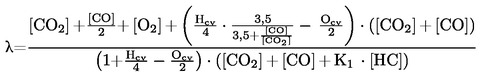
where:
|
[ ] |
= |
Concentration in per cent volume |
||||||
|
K1 |
= |
Conversion factor for NDIR measurement to FID measurement (provided by manufacturer of measuring equipment) |
||||||
|
Hcv |
= |
Atomic ratio of hydrogen to carbon
|
||||||
|
Ocv |
= |
Atomic ratio of oxygen to carbon
|
(9) Document TRANS/WP.29/78/REV.1/Amend.2.
(10) On the basis of actual in-service data to be supplied before 31 December 2003, the requirements of this paragraph may be reviewed and consider (a) whether the definition of outlying emitter needs to be revised with respect to vehicles that have been type-approved according to the limit values given in row B of the table in paragraph 5.3.1.4, (b) whether the procedure for identifying outlying emitters should be amended and (c) whether the procedures for in-service conformity testing should be replaced at an appropriate time by a new statistical procedure. If appropriate it will be proposed the necessary amendments.
(11) For any vehicle, the ‘intermediate zone’ is determined as follows: The vehicle shall meet the conditions given in either paragraph 3.2.1 or paragraph 3.2.1 and, in addition, the measured value for the same regulated pollutant shall be below a level that is determined from the product of the limit value for the same regulated pollutant given in row A of the table in paragraph 5.3.1.4 multiplied by a factor of 2,5.
(12) For any vehicle, the ‘failure zone’ is determined as follows. The measured value for any regulated pollutant exceeds a level that is determined from the product of the limit value for the same regulated pollutant given in row A of the table in paragraph 5.3.1.4. multiplied by a factor of 2,5.
(13) Strike out what does not apply.
(14) This value shall be rounded-off to the nearest tenth of a millimetre.
(15) This value shall be calculated with π = 3,1416 and rounded-off to the nearest cm3.
(16) Specify the tolerance.
(17) CVT — Continuously variable transmission.
(18) See paras. 2.19 and 5.3.1.4 of this Regulation.
(19) It should be noted that the time of two seconds allowed includes the time for changing gear and, if necessary, a certain amount of latitude to catch up with the cycle.
(20) PM = gearbox in neutral, clutch engaged. K1, K2 = first or second gear engaged, clutch disengaged.
|
PM |
= |
gearbox on neutral, clutch engaged. |
|
K1, K5 |
= |
first or second gear engaged, clutch disengaged. |
(22) Additional gears can be used according to manufacturer recommendations if the vehicle is equipped with a transmission with more than five gears.
(23) For HEV, and until uniform technical provisions have been established, the manufacturer will agree with the technical service concerning the status of the vehicle when performing the test as defined in this appendix.
(24) In ppm carbon equivalent.
(25) The values quoted in the specifications are ‘true values’. In establishment of their limit values the terms of ISO 4259 ‘Petroleum products — Determination and application of precision data in relation to methods of test’ have been applied and in fixing a minimum value, a minimum difference of 2R above zero has been taken into account; in fixing a maximum and minimum value, the minimum difference is 4R (R = reproducibility).
Notwithstanding this measure, which is necessary for technical reasons, the manufacturer of fuels should nevertheless aim at a zero value where the stipulated maximum value is 2R and at the mean value in the case of quotations of maximum and minimum limits. Should it be necessary to clarify the questions as to whether a fuel meets the requirements of the specifications, the terms of ISO 4259 should be applied.
(26) The fuel may contain oxidation inhibitors and metal deactivators normally used to stabilise refinery gasoline streams, but detergent/dispersive additives and solvent oils must not be added.
(27) The actual sulphur content of the fuel used for the Type I test shall be reported.
(28) The values quoted in the specifications are ‘true values’. In establishment of their limit values the terms of ISO 4259 ‘Petroleum products — Determination and application of precision data in relation to methods of test’ have been applied and in fixing a minimum value, a minimum difference of 2R above zero has been taken into account; in fixing a maximum and minimum value, the minimum difference is 4R (R = reproducibility).
Notwithstanding this measure, which is necessary for technical reasons, the manufacturer of fuels should nevertheless aim at a zero value where the stipulated maximum value is 2R and at the mean value in the case of quotations of maximum and minimum limits. Should it be necessary to clarify the questions as to whether a fuel meets the requirements of the specifications, the terms of ISO 4259 should be applied.
(29) The range for cetane number is not in accordance with the requirements of a minimum range of 4R. However, in the case of a dispute between fuel supplier and fuel user, the terms of ISO 4259 may be used to resolve such disputes provided replicate measurements, of sufficient number to archive the necessary precision, are made in preference to single determinations.
(30) The actual sulphur content of the fuel used for the Type I test shall be reported.
(31) Even though oxidation stability is controlled, it is likely that shelf life will be limited. Advice should be sought from the supplier as to storage conditions and life.
(32) The values quoted in the specifications are ‘true values’. In establishment of their limit values the terms of ISO 4259 ‘Petroleum products — Determination and application of precision data in relation to methods of test’ have been applied and in fixing a minimum value, a minimum difference of 2R above zero has been taken into account; in fixing a maximum and minimum value, the minimum difference is 4R (R = reproducibility).
Notwithstanding this measure, which is necessary for technical reasons, the manufacturer of fuels should nevertheless aim at a zero value where the stipulated maximum value is 2R and at the mean value in the case of quotations of maximum and minimum limits. Should it be necessary to clarify the questions as to whether a fuel meets the requirements of the specifications, the terms of ISO 4259 should be applied.
(33) The fuel may contain oxidation inhibitors and metal deactivators normally used to stabilise refinery gasoline streams, but detergent/dispersive additives and solvent oils must not be added.
(34) The actual sulphur content of the fuel used for the Type I test shall be reported.
(35) The values quoted in the specifications are ‘true values’. In establishment of their limit values the terms of ISO 4259 ‘Petroleum products — Determination and application of precision data in relation to methods of test’ have been applied and in fixing a minimum value, a minimum difference of 2R above zero has been taken into account; in fixing a maximum and minimum value, the minimum difference is 4R (R = reproducibility).
Notwithstanding this measure, which is necessary for technical reasons, the manufacturer of fuels should nevertheless aim at a zero value where the stipulated maximum value is 2R and at the mean value in the case of quotations of maximum and minimum limits. Should it be necessary to clarify the questions as to whether a fuel meets the requirements of the specifications, the terms of ISO 4259 should be applied.
(36) The range for cetane number is not in accordance with the requirements of a minimum range of 4R. However, in the case of a dispute between fuel supplier and fuel user, the terms of ISO 4259 may be used to resolve such disputes provided replicate measurements, of sufficient number to archive the necessary precision, are made in preference to single determinations.
(37) The actual sulphur content of the fuel used for the Type I test shall be reported.
(38) Even though oxidation stability is controlled, it is likely that shelf life will be limited. Advice should be sought from the supplier as to storage conditions and life.
(39) The values quoted in the specifications are ‘true values’. In establishment of their limit values the terms of ISO 4259 ‘Petroleum products — Determination and application of precision data in relation to methods of test’ have been applied and in fixing a minimum value, a minimum difference of 2R above zero has been taken into account; in fixing a maximum and minimum value, the minimum difference is 4R (R = reproducibility).
Notwithstanding this measure, which is necessary for technical reasons, the manufacturer of fuels should nevertheless aim at a zero value where the stipulated maximum value is 2R and at the mean value in the case of quotations of maximum and minimum limits. Should it be necessary to clarify the questions as to whether a fuel meets the requirements of the specifications, the terms of ISO 4259 should be applied.
(40) The fuel may contain oxidation inhibitors and metal deactivators normally used to stabilise refinery gasoline streams, but detergent/dispersive additives and solvent oils must not be added.
(41) The actual sulphur content of the fuel used for the Type VI test shall be reported.
(42) This method may not accurately determine the presence of corrosive materials if the sample contains corrosion inhibitors or other chemicals which diminish the corrosivity of the sample to the copper strip. Therefore, the addition of such compounds for the sole purpose of biasing the test method is prohibited.
(43) This method may not accurately determine the presence of corrosive materials if the sample contains corrosion inhibitors or other chemicals which diminish the corrosivity of the sample to the copper strip. Therefore, the addition of such compounds for the sole purpose of biasing the test method is prohibited.
(44) Inerts (different from N2) + C2 + C2+.
(45) Value to be determined at 293,2 K (20 °C) and 101,3 kPa.
(46) Value to be determined at 273,2 K (0 °C) and 101,3 kPa.
(47) For compression-ignition engines.
(48) Except vehicles the maximum mass of which exceeds 2 500 kg.
(49) And those category M vehicles which are specified in note 2.
(50) International Standard ISO 2575-1982 (E), entitled ‘Road vehicles: Symbols for control indicators and tell-tales’, Symbol Number 4.36.
(51) This requirement is only applicable from 1 January 2003 to new types of vehicles with an electronic speed input to the engine management. It applies to all vehicles entering into service from 1 January 2005.
(52) Also known as ‘externally chargeable’.
(53) Also known as ‘not externally chargeable’.
(54) For instance: sport, economic, urban, extra-urban position …
(55) Most electric hybrid mode:
The hybrid mode which can be proven to have the highest electricity consumption of all selectable hybrid modes when tested in accordance with condition A of paragraph 4 of Annex 10 to Regulation No 101, to be established based on information provided by the manufacturer and in agreement with the technical service.
(56) Most fuel consuming mode:
The hybrid mode which can be proven to have the highest fuel consumption of all selectable hybrid modes when tested in accordance with condition B of paragraph 4 of Annex 10 to Regulation No 101, to be established based on information provided by the manufacturer and in agreement with the technical service.
|
9.3.2007 |
EN |
Official Journal of the European Union |
L 70/355 |
Corrigendum to Regulation No 123 of the Economic Commission for Europe of the United Nations (UN/ECE) — Uniform provisions concerning the approval of adaptive front-lighting systems (AFS) for motor vehicles
( Official Journal of the European Union L 375 of 27 December 2006 )
Regulation No 123 should read as follows:
Regulation No 123 of the Economic Commission for Europe of the United Nations (UN/ECE) — Uniform provisions concerning the approval of adaptive front-lighting systems (AFS) for motor vehicles
A. ADMINISTRATIVE PROVISIONS
SCOPE
This Regulation applies to adaptive front-lighting systems (AFS) for motor vehicles.
1. DEFINITIONS
For the purpose of this Regulation:
1.1. the definitions given in Regulation No 48 and its series of amendments in force at the time of application for approval shall apply;
1.2. ‘Adaptive front lighting system’ (or ‘system’) means a lighting device, providing beams with differing characteristics for automatic adaptation to varying conditions of use of the dipped-beam (passing beam) and, if it applies, the main-beam (driving-beam) with a minimum functional content as indicated in paragraph 6.1.1.; such systems consist of the ‘system control’, one or more ‘supply and operating device(s)’, if any, and the ‘installation units’ of the right and of the left side of the vehicle;
1.3. ‘Class’ of a passing beam (C, V, E or W) means the designation of a passing beam, identified by particular provisions according to this Regulation and Regulation No 48 (1);
‘Mode’ of a front-lighting function provided by a systemmeans a beam within the provisions (see paragraphs 6.2. and 6.3. of this Regulation) either for one of the passing beam classes or for the main beam, designed and specified by the manufacturer for adaptation to dedicated vehicle and ambient conditions;
1.4.1. ‘Bending mode’ means the designation of a mode of a front-lighting function with its illumination being laterally moved or modified (to obtain an equivalent effect), designed for bends, curves or intersections of the road, and, identified by particular photometric provisions;
1.4.2. ‘Category 1 bending mode’ means a bending mode with horizontal movement of the kink of the cut-off;
1.4.3. ‘Category 2 bending mode’ means a bending mode without horizontal movement of the kink of the cut-off;
1.5. ‘Lighting unit’ means a light emitting part of the system, which may consist of optical, mechanical and electrical components, designed to provide or contribute to the beam of one or more front-lighting function(s) provided by the system;
1.6. ‘Installation unit’ means an indivisible housing (lamp body) which contains one or more lighting unit(s);
1.7. ‘Right side’ respectively ‘left side’ means the combined total of the lighting units intended to be installed to that side of the longitudinal median plane of the vehicle, relative to its forward motion;
1.8. ‘System control’ means that part(s) of the system receiving the signals from the vehicle and controlling the operation of the lighting units automatically;
1.9. ‘Neutral state’ means the state of the system when a defined mode of the class C passing beam (‘basic passing beam’) or of the main beam, if any, is produced, and no AFS control signal applies;
1.10. ‘Signal’ means any AFS control signal as defined in Regulation No 48 or, any additional control input to the system or, a control output from the system to the vehicle;
1.11. ‘Signal generator’ means a device, reproducing one or more of the signals for system tests;
1.12. ‘Supply and operating device’ means one or more components of a system providing power to one or more parts of the system, including such as power and/or voltage control(s) for one or more light sources as e.g. electronic light source control gears;
1.13. ‘System reference axis’ means the intersection line of the vehicle's longitudinal median plane with the horizontal plane through the centre of reference of one lighting unit specified in the drawings according to paragraph 2.2.1. below;
1.14. ‘Lens’ means the outermost component of an installation unit, which transmits light through the illuminating surface;
1.15. ‘Coating’ means any product(s) applied in one or more layers to the outer face of a lens;
Systems of different ‘types’ means systems which differ in such essential respects as:
1.16.1. the trade name or mark(s);
1.16.2. the inclusion or elimination of components capable of altering optical characteristics/photometric properties of the system;
1.16.3. suitability for right-hand or left-hand traffic or for both traffic systems;
1.16.4. the front-lighting function(s), mode(s) and classes produced;
1.16.5. the materials constituting the lenses and coatings, if any;
1.16.6. the characteristic(s) of the signal(s), specified for the system;
1.17. ‘Aiming’ means the positioning of the beam or part thereof on an aiming screen according to the relevant criteria;
1.18. ‘Adjustment’ means the use of the means provided by the system for vertical and/or horizontal aiming of the beam;
1.19. ‘Traffic-change function’ means any front-lighting function or a mode thereof, or part(s) thereof only, or any combination of these, intended to avoid glare and provide sufficient illumination in case where a vehicle being equipped with a system designed for one traffic direction only is temporarily used in a country with the opposite direction of traffic.
1.20. ‘Substitute function’ means any specified front-lighting and/or front light-signalling, be it a front-lighting and/or a front light-signalling function, or a mode thereof, or part(s) thereof only, or any combination of it, intended to replace a front-lighting function/mode in case of failure.
2. APPLICATION FOR APPROVAL OF A SYSTEM
The application for approval shall be submitted by the owner of the trade name or mark or by his duly accredited representative.
It shall specify:
the front-lighting functions, which are intended to be provided by the system, for which Approval is sought according to this Regulation;
2.1.1.1. any other front-lighting or front light signalling function(s), provided by any lamp(s) being grouped, combined or reciprocally incorporated to the lighting units of the system, for which Approval is sought; sufficient information for identification of the respective lamp(s) and indication of the Regulation(s), according to which they are intended to be (separately) approved;
2.1.2. whether the passing beam is designed for both left-hand and right-hand traffic or for either left-hand or right-hand traffic only;
if the system is equipped with one or more adjustable lighting unit(s):
2.1.3.1. the mounting position(s)of the respective lighting unit(s) in relation to the ground and the longitudinal median plane of the vehicle;
2.1.3.2. the maximum angles above and below the normal position(s) which the device(s) for vertical adjustment can achieve;
2.1.4. the category, as listed in Regulation No 37 or 99, of replaceable and/or non-replaceable light source(s) used;
if the system is equipped with one or more non-replaceable light source(s):
2.1.5.1. identification of the lighting unit(s) of which said light source(s) is/are a non-replaceable part;
2.1.6. the operation conditions e.g. different input voltages according to the provisions of the Annex 9 to this Regulation, if applicable.
Every application for approval shall be accompanied by:
2.2.1. drawings in triplicate in sufficient detail to permit identification of the type, showing the position(s) intended for the approval number(s) and the additional symbols in relation to the circle(s) of the approval mark(s), and showing in what geometrical position the lighting units are to be mounted on the vehicle in relation to ground and vehicle longitudinal median plane, and showing each of them in vertical (axial) section and in front elevation, with main details of the optical design including the axis/axes of reference and the point(s) to be taken as centre(s) of reference in the tests and any optical features, of the lens, if applicable;
a concise technical description of the system specifying:
|
(a) |
the lighting function(s) and their modes to be provided by the system (2); |
|
(b) |
the lighting units contributing to each of them (2), and the signals (3) with the technical characteristics relevant to their operation; |
|
(c) |
which categories (2) of the bending mode requirements apply, if any; |
|
(d) |
which additional data set(s) of class E passing beam provisions according to Table 6 of Annex 3 of this Regulation apply, if any; |
|
(e) |
which set(s) of class W passing beam provisions according to Annex 3 of this Regulation apply, if any; |
|
(f) |
which lighting units (3) provide or contribute to one or more passing beam cut-off(s); |
|
(g) |
the indication(s) (2) according to the provisions of paragraph 6.4.6. of this Regulation with respect to the paragraphs 6.22.6.1.2.1. and 6.22.6.1.3. of Regulation No 48; |
|
(h) |
which lighting units are designed to provide the minimum passing beam illumination according to the paragraph 6.2.9.1. of this Regulation; |
|
(i) |
mounting and operation specifications for test purposes; |
|
(j) |
any other relevant information; |
2.2.2.1. the safety concept as laid down in the documentation, which, to the satisfaction of the Technical Service responsible for type approval tests:
|
(i) |
describes the measures designed into the system to ensure compliance with the provisions of paragraphs 5.7.3., 5.9., 6.2.6.4. below, and |
|
(ii) |
indicates the instructions for their verification according to paragraph 6.2.7. below; and/or |
|
(iii) |
gives access to the relevant documents demonstrating the system's performance concerning sufficient reliability and safe operation of the measures specified according to the paragraph 2.2.2.1. (i) above, e.g. FMEA (‘Failure Mode and Effect Analysis’), FTA (‘Fault Tree Analysis’) or any similar process appropriate to system safety considerations. |
2.2.2.2. the make and type of supply and operating device(s), if any and if not being part of an installation unit;
2.2.3. two samples of the type of system, for which approval is sought, including the mounting devices, supply and operating devices, and signal generators if any;
for the test of plastic material of which the lenses are made:
fourteen lenses;
2.2.4.1.1. ten of these lenses may be replaced by ten samples of material at least 60 × 80 mm in size, having a flat or convex outer surface and a substantially flat area (radius of curvature not less than 300 mm) in the middle measuring at least 15 × 15 mm;
2.2.4.1.2. every such lens or sample of material shall be produced by the method to be used in mass production;
2.2.4.2. a lighting element or optical assembly, if applicable, to which the lenses can be fitted in accordance with the manufacturer's instructions;
2.2.5. for testing the resistance of the light transmitting components made of plastic material against UV radiation of those light source(s) inside the system, which can emit UV radiation as e.g. gas discharge light sources, according to paragraph 2.2.4. of Annex 6 to this Regulation:
one sample of each relevant material being used in the system or one system or part(s) thereof, containing these. Each material sample shall have the same appearance and surface treatment, if any, as intended for use in the system to be approved;
2.2.6. the materials making up the lenses and coatings, if any, shall be accompanied by the test report of the characteristics of these materials and coatings if they have already been tested;
2.2.7. in case of a system according to paragraph 4.1.7. below, a vehicle representative of the vehicle(s) indicated according to paragraph 4.1.6. below.
3. MARKINGS
3.1. The installation units of a system submitted for approval shall bear the trade name or mark of the applicant.
They shall comprise each, on the lenses and on the main bodies spaces of sufficient size for the approval mark and the additional symbols referred to in paragraph 4.; these spaces shall be indicated on the drawings referred to in paragraph 2.2.1. above.
3.2.1. If however the lens cannot be detached from the main body of the installation unit, one marking as per paragraph 4.2.5. shall be sufficient.
3.3. The installation units or systems designed to satisfy the requirements both of right-hand and of left-hand traffic shall bear markings indicating the two settings of the optical element(s) on the vehicle or of the light source(s) on the reflector(s); these markings shall consist of the letters ‘R/D’ for the position for right-hand traffic and the letters ‘L/G’ for the position for left-hand traffic.
3.4. In the case of a system designed to meet the requirements set out in paragraph 5.8.2. below by means of, or using additionally, an area on the front lens(es) of the installation unit(s) which can be occulted, this area must be outlined indelibly. This marking is not necessary, however, where the area is clearly apparent.
4. APPROVAL
4.1. General
4.1.1. If all the samples of a type of a system submitted pursuant to paragraph 2. above satisfy the provisions of this Regulation, approval shall be granted.
4.1.2. Where lamps being grouped, combined or reciprocally incorporated with the system satisfy the requirements of more than one Regulation, a single international approval mark may be affixed provided that each of the grouped, combined or reciprocally incorporated lamps satisfies the provisions applicable to it.
4.1.3. An approval number shall be assigned to each type approved. Its first two digits (at present 00) shall indicate the series of amendments incorporating the most recent major technical amendments made to the Regulation at the time of issue of the approval. The same Contracting Party may not assign the same number to another type of system covered by this Regulation.
Notice of approval or of extension or refusal or withdrawal of approval or production definitely discontinued of a type of system pursuant to this Regulation shall be communicated to the Parties to the 1958 Agreement applying this Regulation, by means of a form conforming to the model in Annex 1 to this Regulation, with the indications according to paragraph 2.1.3.
4.1.4.1. if the installation unit(s) is/are equipped with an adjustable reflector and if this/these installation unit(s) is/are to be used only in mounting positions according to the indications in paragraph 2.1.3. the applicant shall be obliged by approval to inform the user in a proper way about the correct mounting position(s).
4.1.5. In addition to the mark prescribed in paragraph 3.1., an approval mark as described in paragraphs 4.2. and 4.3. below shall be affixed in the spaces referred to in paragraph 3.2. above to every installation unit of a system conforming to a type approved under this Regulation.
4.1.6. The applicant shall indicate in a form corresponding to the respective model in the Annex 1 to this Regulation, the vehicle(s) for which the system is intended.
If approval is sought for a system which is not intended to be included as part of the approval of a vehicle type according to Regulation No 48,
4.1.7.1. the applicant shall submit sufficient documentation to prove the capability of the system to comply with the provisions of paragraph 6.22. of Regulation No 48 when correctly installed, and
4.1.7.2. the system shall be approved according to Regulation No 10.
4.2. Composition of the approval mark
The approval mark shall consist of:
An international approval marking, comprising:
4.2.1.1. a circle surrounding the letter ‘E’ followed by the distinguishing number of the country which has granted approval (4);
4.2.1.2. the approval number prescribed in paragraph 4.1.3. above;
the following additional symbol (or symbols):
4.2.2.1. on a system, the letter ‘X’, and those of the function(s) being provided by the system:
|
‘C’ |
for the class C passing beam, with the addition of symbols for the relevant other classes of passing beam, |
|
‘E’ |
for a class E passing beam, |
|
‘V’ |
for a class V passing beam, |
|
‘W’ |
for a class W passing beam, |
|
‘R’ |
for a driving beam; |
4.2.2.2. in addition to each symbol and above it a score, if the lighting function or mode thereof is provided by more than one installation unit from one or both side(s);
4.2.2.3. in addition the symbol ‘T’, after the symbol(s) of all lighting function(s) and/or class(es) designed to comply with the respective bend lighting provisions, with said symbol(s) arranged together and leftmost;
4.2.2.4. on a separate installation unit, the letter ‘X’, and those of the function(s) being provided by the lighting unit(s) comprised in it;
4.2.2.5. if the installation unit on a given side is not the only contributor to a lighting function or mode of a lighting function it shall bear a score above the symbol of the function;
4.2.2.6. on a system or part thereof meeting left-hand traffic requirements only, a horizontal arrow pointing to the right of an observer facing the installation unit, i.e. to the side of the road on which the traffic moves;
4.2.2.7. on a system or part thereof designed to meet the requirements of both traffic systems e.g. by means of an appropriate adjustment of the setting of the optical element or the light source, a horizontal arrow with a head on each end, the heads pointing respectively to the left and to the right;
4.2.2.8. on an installation unit incorporating a lens of plastic material, the group of letters ‘PL’ to be affixed near the symbols prescribed in paragraphs 4.2.2.1. to 4.2.2.7. above;
4.2.2.9. on an installation unit contributing to fulfil the requirements of this Regulation in respect of the driving beam, an indication of the maximum luminous intensity expressed by the reference mark, as defined in paragraph 6.3.2.1.3. below, placed near the circle surrounding the letter ‘E’;
In every case the relevant operating mode used during the test procedure according to paragraph 1.1.1.1. of Annex 4 and the permitted voltage(s) according to paragraph 1.1.1.2. of Annex 4 shall be stipulated on the approval forms and on the communication forms transmitted to the countries which are Contracting Parties to the Agreement and which apply this Regulation.
In the corresponding cases, the system or part(s) thereof shall be marked as follows:
4.2.3.1. on an installation unit meeting the requirements of this Regulation which is so designed that the light source(s) of the passing beam shall not be lit simultaneously with that of any other lighting function with which it may be reciprocally incorporated: an oblique stroke (/) shall be placed after the passing beam symbol(s) in the approval mark.
4.2.3.2. on an installation unit meeting the requirements of Annex 4 to this Regulation only when supplied with a voltage of 6 V or 12 V, a symbol consisting of the number 24 crossed out by an oblique cross (X), shall be placed near the holders of the light source(s).
4.2.4. The two digits of the approval number (at present 00) which indicate the series of amendments incorporating the most recent major technical amendments made to the Regulation at the time of issue of the approval and, if necessary, the required arrow may be marked close to the above additional symbols.
4.2.5. The marks and symbols referred to in paragraphs 4.2.1. and 4.2.2. above shall be clearly legible and be indelible. They may be placed on an inner or outer part (transparent or not) of the installation unit which cannot be separated from its light-emitting surface(s). In any case it shall be visible when the installation unit(s) is/are fitted on the vehicle. The displacement of a movable part of the vehicle is permitted to fulfil this requirement.
4.3. Arrangement of the approval mark
4.3.1. Independent lamps
Annex 2, Figures 1 to 10, to this Regulation gives examples of arrangements of the approval mark with the above-mentioned additional symbols.
Grouped, combined or reciprocally incorporated lamps
Where lamps being grouped, combined or reciprocally incorporated with the system have been found to comply with the requirements of several Regulations, a single international approval mark may be affixed, consisting of a circle surrounding the letter ‘E’ followed by the distinguishing number of the country which has granted the approval, and an approval number. This approval mark may be located anywhere on the grouped, combined or reciprocally incorporated lamps, provided that:
4.3.2.1.1. it is visible as per paragraph 4.2.5.;
4.3.2.1.2. no part of the grouped, combined or reciprocally incorporated lamps that transmit light can be removed without at the same time removing the approval mark.
The identification symbol for each lamp appropriate to each Regulation under which approval has been granted, together with the corresponding series of amendments incorporating the most recent major technical amendments to the Regulation at the time of issue of the approval, and if necessary, the required arrow shall be marked:
4.3.2.2.1. either on the appropriate light-emitting surface,
4.3.2.2.2. or in a group, in such a way that each of the grouped, combined or reciprocally incorporated lamps may be clearly identified (see for possible examples in Annex 2).
4.3.2.3. The size of the components of a single approval mark shall not be less than the minimum size required for the smallest of the individual marks by the Regulation under which approval has been granted.
4.3.2.4. An approval number shall be assigned to each type approved. The same Contracting Party may not assign the same number to another type of grouped, combined or reciprocally incorporated lamps covered by this Regulation.
4.3.2.5. Annex 2, Figure 11 and 12, to this Regulation give examples of arrangements of approval marks for grouped, combined or reciprocally incorporated lamps with all the above-mentioned additional symbols, and relating to a system with functions provided by more than one installation unit per side of the vehicle.
4.3.2.6. Annex 2, Figure 13, to this Regulation give examples of approval marks relating to the complete system.
B. TECHNICAL REQUIREMENTS FOR SYSTEMS OR PART(S) OF A SYSTEM
Unless otherwise specified, photometric measurements shall be carried out according to the provisions set out in the Annex 9 to this Regulation.
5. GENERAL SPECIFICATIONS
Each sample, when its approval is sought for right-hand traffic only, shall conform to the specifications set forth in paragraphs 6. and 7. below; if however its approval is sought for left-hand traffic, the provisions of paragraph 6. below, including the relevant Annexes to this Regulation, apply with the inversion of right to left and vice versa.
Correspondingly, the designation of the angular positions and elements is adjusted by exchanging ‘R’ for ‘L’ and vice versa.
5.1.2. Systems or part(s) thereof, shall be so made as to retain their prescribed photometric characteristics and to remain in good working order when in normal use, in spite of the vibrations to which they may be subjected.
Systems or part(s) thereof, shall be fitted with a device enabling them to be so adjusted on the vehicle as to comply with the rules applicable to them.
5.2.1. Such adjustment device(s) need not be fitted on systems or part(s) thereof, provided that their use is confined to vehicles on which the setting can be adjusted by other means or no such means are needed according to the applicant's system description.
The system shall not be equipped with light sources that are not approved according to Regulation No 37 or 99;
5.3.1. If a light source is replaceable, its lamp holder shall conform to the dimensional characteristics given on the data sheet of IEC Publication No 60061-2, as referred to in the relevant light source Regulation;
5.3.2. If a light source is non-replaceable, it shall not be a part of a lighting unit that provides the passing beam in the neutral state.
5.4. System(s) or part(s) thereof, designed to satisfy the requirements both of right-hand and of left-hand traffic may be adapted for traffic on a given side of the road either by an appropriate initial setting when fitted on the vehicle or by selective setting by the user. In any case, only two different and clearly distinct settings, one for right-hand and one for left-hand traffic, shall be possible, and the design shall preclude inadvertent shifting from one setting to the other or setting in an intermediate state.
5.5. Complementary tests shall be done according to the requirements of Annex 4 of this Regulation to ensure that in use there is no excessive change in photometric performance.
5.6. If the lens of a lighting unit is of plastic material, tests shall be done according to the requirements of Annex 6 to this Regulation.
On a system or part(s) of, designed to provide alternately the driving beam and the passing beam, any mechanical, electro-mechanical or other device incorporated in the lighting unit(s), for switching from one to the other beam shall be so constructed that:
5.7.1. the device is strong enough to withstand 50 000 operations without suffering damage despite the vibrations to which it may be subjected in normal use;
5.7.2. either the passing beam or the driving beam shall always be obtained, without any possibility of remaining in an intermediate or undefined state; if this is not possible, such a state must comply with the provisions of paragraph 5.7.3. below;
5.7.3. in the case of failure it must be possible to obtain automatically a passing beam or a state with respect to the photometric conditions which yields values not exceeding 1,5 lx in the zone III b as defined in Annex 3 to this Regulation and at least 4 lx in a point of ‘segment Emax’, by such means as e.g. switching off, dimming, aiming downwards, and/or functional substitution;
5.7.4. the user cannot, with ordinary tools, change the shape or position of the moving parts, or influence the switching device.
Systems shall provide means allowing them to be used temporarily in a territory with the opposite direction of driving than that for which approval is sought, without causing undue dazzle to the oncoming traffic. For these purposes the system(s) or part(s) thereof shall:
5.8.1. be capable of providing a selective setting by the user according to paragraph 5.4. above, without special tools; or
provide means to achieve a traffic-change function, producing not more than 1,5 lx in zone IIIb for the opposite direction of traffic and not less than 6 lx in 50V when tested according to paragraph 6.2. below with the adjustment left unchanged compared to that for the original traffic direction; where
5.8.2.1. the occultation of a respective lens area according to paragraph 3.4. above may be such means or part of it.
5.9. The system shall be so made that, if a light source has failed, a failure signal in order to comply with the relevant provisions of Regulation No 48 shall be provided.
5.10. The component(s) to which a replaceable light source is assembled shall be so made that the light source fits easily and, even in darkness, can be fitted in no position but the correct one.
In the case of a system according to paragraph 4.1.7. above.
5.11.1. The system shall be accompanied by a copy of the form according to paragraph 4.1.4. above and instructions to enable its installation according to the provisions of Regulation No 48.
5.11.2. The Technical Service responsible for type approval shall verify that:
|
(a) |
the system can be correctly installed according to said instructions; |
|
(b) |
the system, when installed in the vehicle, complies with the provisions of paragraph 6.22. of Regulation No 48; to confirm compliance with the provisions of paragraph 6.22.7.4. of Regulation No 48 a test drive is mandatory, which comprises any situation relevant to the system control on the basis of the applicant's description. It shall be notified whether all modes are activated, performing and de-activated according to the applicant's description; obvious malfunctioning, if any, to be contested (e.g. angular excess or flicker). |
6. ILLUMINATION
6.1. General provisions
6.1.1. Each system shall provide a class C passing beam according to paragraph 6.2.5. below and one or more passing beam(s) of additional class(es); it may incorporate one or more additional modes within each class of passing beam and the front-lighting functions according to paragraph 6.3. and/or 2.1.1.1. of this Regulation.
6.1.2. The system shall provide automatic modifications, such that good road illumination is achieved and no discomfort is caused, either to the driver or to other road users.
6.1.3. The system shall be considered acceptable if it meets the relevant photometric requirements of paragraphs 6.2. and 6.3.
Photometric measurements shall be performed according to the applicants description:
6.1.4.1. at neutral state according to paragraph 1.9.;
6.1.4.2. at V-signal, W-signal, E-signal, T-signal according to paragraph 1.10., whichever apply;
6.1.4.3. if applicable, at any other signal(s) according to paragraph 1.10. and combinations of them, according to the applicant's specification.
6.2. Provisions concerning passing beam
The system shall, prior to the subsequent test procedures, be set to the neutral state, emitting the class C passing beam.
For each side of the system (vehicle) the passing beam in its neutral state shall produce from at least one lighting unit a ‘cut-off’ as defined in Annex 8 to this Regulation or,
6.2.1.1. the system shall provide other means, e.g. optical features or temporary auxiliary beams, allowing for unambiguous and correct aiming.
6.2.1.2. Annex 8 does not apply to the traffic-change function as described in paragraph 5.8. through 5.8.2.1. above.
6.2.2. The system or part(s) thereof shall be so aimed that the position of the cut-off complies with the requirements indicated in Table 2 of Annex 3 to this Regulation.
6.2.3. When so aimed, the system or part(s) thereof, if its approval is sought solely for provision of the passing beam, needs to comply with the requirements set out in the relevant paragraphs below; if it is intended to provide additional lighting or light signalling functions according to the scope of this Regulation, it shall comply in addition with the requirements set out in the relevant paragraphs below, if not being adjustable independently.
6.2.4. Where a system or any part(s) thereof so aimed do not meet the requirements as indicated in paragraph 6.2.3. above, its alignment may, according to the instructions of the manufacturer, be changed, within 0,5 deg to the right or left and vertically 0,2 deg up or down, with respect to the initial aiming.
6.2.5. When emitting a specified mode of the passing beam, the system shall meet the requirements in the respective section (C, V, E, W) of part A of Table 1 (photometric values) and in Table 2 (Emax and ‘cut-off’ positions) of Annex 3 to this Regulation, as well as section 1 (‘cut-off’ requirements) of Annex 8 to this Regulation.
A bending mode may be emitted, provided that:
6.2.6.1. the system meets the respective requirements of part B of Table 1 (photometric values) and item 2 of Table 2 (‘cut-off’ provisions) of Annex 3 to this Regulation, when measured according to the procedure indicated in Annex 9, relevant to the category (either category 1 or category 2) of the bending mode, for which approval is sought;
6.2.6.2. Emax of the illumination does not lie outside of the rectangle extending from the uppermost vertical position specified in Table 2 of Annex 3 to this Regulation for the respective passing beam class, to 2 deg below H-H and from 45 deg left to 45 deg right of the system reference axis;
6.2.6.3. when the T-signal corresponds to the vehicle's smallest turn radius to the left (or right), the system provides at least 3 lx at one or more points in the zone extending from H-H to 2 deg below H-H and from 10 to 45 deg left (or right) of the system reference axis;
6.2.6.4. if approval is sought for a category 1 bending mode, the use of the system is restricted to vehicles where provisions are taken such that the horizontal position of the ‘kink’ of the ‘cut-off’ which is provided by the system, complies with the relevant provisions of paragraph 6.22.7.4.5. (i) of Regulation No 48;
if approval is sought for a category 1 bending mode, the system is designed so that, in the case of a failure affecting the lateral movement or modification of the illumination, it must be possible to obtain automatically either photometric conditions corresponding to paragraph 6.2.5. above or a state with respect to the photometric conditions which yields values not exceeding 1,5 lx in the zone IIIb, as defined in Annex 3 to this Regulation, and at least 4 lx in a point of ‘segment Emax’;
6.2.6.5.1. however, this is not needed, if for positions relative to the system reference axis up to 5 deg left, at 0,3 deg up from H-H, and greater than 5 deg left, at 0,57 deg up, a value of 1 lx is in no case exceeded.
6.2.7. The system shall be checked on the basis of the relevant instructions of the manufacturer, indicated in the safety concept according to paragraph 2.2.2.1. above.
6.2.8. A system or part(s) thereof, designed to meet the requirements of both right-hand and left-hand traffic must, in each of the two setting positions, according to 5.4. above meet the requirements specified for the corresponding direction of traffic.
The system shall be so made that:
6.2.9.1. any specified passing beam mode provides at least 3 lx at point 50 V from each side of the system;
the mode(s) of the Class V passing beam are exempted from this requirement;
6.2.9.2. four seconds after switching on the system, which has not been operated for 30 minutes or more, at least 5 lx must be reached at point 50 V of the class C passing beam;
6.2.9.3. other modes:
when signal inputs according to paragraph 6.1.4.3. of this Regulation apply, the requirements of the paragraph 6.2. shall be fulfilled.
6.3. Provisions concerning driving beam
The system shall, prior to the subsequent test procedures, be set to the neutral state.
The lighting unit(s) of the system shall be adjusted, according to the instructions of the manufacturer, such that the area of maximum illumination is centred on the point (HV) of intersection of the lines H-H and V-V;
6.3.1.1. any lighting unit(s) which is/are not independently adjustable, or, for which the aiming was done with respect to any measurements under paragraphs 6.2., shall be tested in its/their unchanged position.
When measured according to the provisions laid down in Annex 9 to this Regulation the illumination shall meet the following requirements.
HV shall be situated within the isolux 80 per cent of maximum illumination of the driving beam.
6.3.2.1.1. This maximum value (EM) shall not be less than 48 lx. The maximum value shall in no circumstances exceed 240 lx;
6.3.2.1.2. The maximum intensity (IM) of each installation unit providing or contributing to the maximum intensity of the driving beam, expressed in thousands of candelas shall be calculated by the formula:
IM = 0,625 EM
6.3.2.1.3. The reference mark (I′M) of this maximum intensity, referred to in paragraph 4.2.2.9. above, shall be obtained by the ratio:

This value shall be rounded off to the value of: 5 - 10 - 12,5 - 17,5 - 20 - 25 - 27,5 - 30 - 37,5 - 40 - 45 - 50.
6.3.2.2. Starting from point HV, horizontally to the right and left, the illumination of the driving beam shall be not less than 24 lx up to 2,6 deg and not less than 6 lx up to 5,2 deg.
The illumination or part thereof emitted by the system may be automatically laterally moved (or modified to obtain an equivalent effect), provided that:
6.3.3.1. the system meets the requirements of the paragraphs 6.3.2.1.1. and 6.3.2.2. above with each lighting unit measured according to the relevant procedure indicated in Annex 9.
The system shall be so made that:
6.3.4.1. the lighting unit(s) of the right side and of the left side provide each at least half of the minimum illumination value of the driving beam as specified by the paragraph 6.3.2.2. above:
6.3.4.2. four seconds after switching on the system, which has not been operated for 30 minutes or more, at least 42 lx must be reached at point HV of the driving beam;
6.3.4.3. When signal inputs according to paragraph 6.1.4.3. of this Regulation apply, the requirements of the paragraph 6.3. shall be fulfilled.
6.3.5. If the specified beam requirements are not met, a re-aiming of the beam position within 0,5 deg up or down and/or 1 deg to the right or left, with respect to its initial aiming is allowed; in the revised position all photometric requirements shall be met. These provisions do not apply to lighting units as indicated under paragraph 6.3.1.1. of this Regulation.
6.4. Other provisions
In the case of a system or part(s) thereof with adjustable lighting units the requirements of paragraphs 6.2. (passing beam), and 6.3. (driving beam) are applicable for each mounting position indicated according to paragraph 2.1.3. (adjustment range). For verification the following procedure shall be used:
6.4.1. Each applied position is realized on the test goniometer with respect to a line joining the centre of reference and point HV on an aiming screen. The adjustable system or part(s) thereof is then moved into such a position that the light pattern on the screen corresponds to the relevant aiming prescriptions;
6.4.2. with the system or part(s) thereof initially fixed according to paragraph 6.4.1., the device or part(s) thereof must meet the relevant photometric requirements of paragraphs 6.2. and 6.3.;
additional tests shall be made after the reflector/system or part(s) thereof has been moved vertically ± 2 deg or at least into the maximum position if less than 2 deg, from its initial position by means of the system or part(s) thereof adjusting device. Having re-aimed the system or part(s) thereof as a whole (by means of the goniometer for example) in the corresponding opposite direction the light output in the following directions shall be controlled and lie within the required limits:
6.4.3.1. passing beam: points HV and 75R, or 50R if applicable; driving beam: IM and point HV (percentage of IM);
6.4.4. if the applicant has indicated more than one mounting position, the procedure of paragraphs 6.4.1. to 6.4.3. shall be repeated for all other positions;
6.4.5. if the applicant has not asked for special mounting positions, the system or part(s) thereof shall be aimed for measurements of paragraphs 6.2. (passing beam) and 6.3. (driving beam) with the relevant adjusting device(s) of the system or part(s) thereof in its mean position. The additional test of paragraph 6.4.3. shall be made with the system or part(s) thereof, moved into its extreme positions (instead of ± 2 deg) by means of the relevant adjusting device(s).
6.4.6. It shall be stated by means of a form conforming to the model in Annex 1 to this Regulation, which lighting unit(s) provide a ‘cut-off’ as defined in Annex 8 of this Regulation, that projects into a zone extending from 6 deg left to 4 deg right and upwards from a horizontal line positioned at 0,8 deg down.
6.4.7. It shall be stated by means of a form conforming to the model in Annex 1 to this Regulation, which class E passing beam mode(s), if any, comply with a ‘data set’ of Table 6 of Annex 3 of this Regulation.
7. COLOUR
7.1. The colour of the light emitted shall be white. Expressed in CIE trichromatic co-ordinates, the light emitted by each part of the system shall be in the following boundaries:
|
limit towards blue |
x ≥ 0,310 |
|
limit towards yellow |
x ≤ 0,500 |
|
limit towards green |
y ≤ 0,150 + 0,640 x |
|
limit towards green |
y ≤ 0,440 |
|
limit towards purple |
y ≥ 0,050 + 0,750 x |
|
limit towards red |
y ≥ 0,382 |
C. FURTHER ADMINISTRATIVE PROVISIONS
8. MODIFICATION OF THE SYSTEM TYPE AND EXTENSION OF APPROVAL
Every modification of the system type shall be notified to the administrative department which approved the system type. The said department may then either:
8.1.1. Consider that the modifications made are unlikely to have appreciable adverse effects and that in any event the system still complies with the requirements; or
8.1.2. Require a further test report from the Technical Service responsible for conducting the tests.
8.2. Confirmation or refusal of approval, specifying the alterations, shall be communicated by the procedure specified in paragraph 4.1.4. above to the Contracting Parties to the Agreement which apply this Regulation.
8.3. The competent authority issuing the extension of approval shall assign a series number to each communication form drawn up for such an extension and inform thereof the other Parties to the 1958 Agreement applying this Regulation by means of a communication form conforming to the model in Annex 1 to this Regulation.
9. CONFORMITY OF PRODUCTION
The conformity of production procedures shall comply with those set out in the Agreement, Appendix 2 (E/ECE/324-E/ECE/TRANS/505/Rev.2) with the following requirements:
9.1. a system approved under this Regulation shall be so manufactured as to conform to the type approved by meeting the requirements set forth in paragraphs 6. and 7.
9.2. the minimum requirements for conformity of production control procedures set fourth in Annex 5 to this Regulation shall be complied with.
9.3. The minimum requirements for sampling by an inspector set forth in Annex 7 to this Regulation shall be complied with.
9.4. The authority which has granted type approval may at any time verify the conformity control methods applied in each production facility. The normal frequency of these verifications shall be once every two years.
9.5. Systems or part(s) thereof with apparent defects are disregarded.
9.6. The reference mark is disregarded.
10. PENALTIES FOR NON-CONFORMITY OF PRODUCTION
10.1. The approval granted in respect of a type of system pursuant to this Regulation may be withdrawn if the requirements are not complied with or if a system or part(s) thereof bearing the approval mark does not conform to the type approved.
10.2. If a Contracting Party to the Agreement applying this Regulation withdraws an approval it has previously granted, it shall forthwith so notify the other Contracting Parties applying this Regulation by means of a communication form conforming to the model in Annex 1 to this Regulation.
11. PRODUCTION DEFINITELY DISCONTINUED
11.1. If the holder of the approval completely ceases to manufacture a type of system approved in accordance with this Regulation, he shall so inform the authority, which granted the approval. Upon receiving the relevant communication, that authority shall inform thereof the other Contracting Parties to the 1958 Agreement applying this Regulation by means of a communication form conforming to the model in Annex 1 to this Regulation.
12. NAMES AND ADDRESSES OF TECHNICAL SERVICES RESPONSIBLE FOR CONDUCTING APPROVAL TESTS, AND OF ADMINISTRATIVE DEPARTMENTS
12.1. The Contracting Parties to the 1958 Agreement applying this Regulation shall communicate to the United Nations Secretariat the names and addresses of the technical services responsible for conducting approval tests and of the administrative departments which grant approval and to which forms certifying approval or extension or refusal or withdrawal of approval, or production definitely discontinued, issued in other countries, are to be sent.
ANNEX 1


ANNEX 2
EXAMPLES OF ARRANGEMENTS OF APPROVAL MARKS
Example 1
a ≥ 8 mm (glass lens)a ≥ 5 mm (plastic lens)
|
|
|
|
Figure 1 |
Figure 2 |
The installation unit of a system, bearing one of the above approval marks has been approved in the Netherlands (E4) pursuant to this Regulation under approval number 19 243, meeting the requirements of this Regulation in its original form (00). The passing beam is designed for right-hand traffic only. The letters ‘CT’ (Figure 1) indicate that it concerns a passing beam with bending mode and the letters ‘CWR’ (Figure 2) indicate that it concerns a class C passing beam and a class W passing beam and a driving beam.
Number 30 indicates that the maximum luminous intensity of the driving beam is between 86 250 and 101 250 candelas.
Note: The approval number and additional symbols shall be placed close to the circle surrounding the letter ‘E’ and either above or below that letter ‘E’, or to the right or left of that letter. The digits of the approval number shall be on the same side of that letter ‘E’ and face in the same direction.
The use of Roman numerals as approval numbers should be avoided so as to prevent any confusion with other symbols.
Example 2
|
|
|
|
Figure 3 |
Figure 4a |
|
|
|
|
Figure 4b |
|
The installation unit of a system, bearing the above approval mark, meets the requirements of this Regulation in respect of both the passing beam and the driving beam and is designed:
Figure 3: class C passing beam with class E passing beam for left-hand traffic only.
Figures 4a and 4b: class C passing beam with class V passing beam for both traffic systems by means of an appropriate adjustment of the setting of the optical element or the light source on the vehicle, and a driving beam. Class C passing beam, class V passing beam and driving beam comply to bending lighting provisions, as indicated by the letter ‘T’. The score above ‘R’ indicates that the driving beam function is provided by more than one installation unit on that side of the system.
Example 3
|
|
|
|
Figure 5 |
Figure 6 |
The installation unit, bearing the above approval mark is incorporating a lens of plastic material and meeting the requirements of this Regulation in respect of the passing beam only and is designed:
Figure 5: class C passing beam and class W passing beam for both traffic systems.
Figure 6: class C passing beam with bending mode for right-hand traffic only.
Example 4
|
|
|
|
Figure 7 |
Figure 8 |
Figure 7: the installation unit, bearing this approval mark is meeting the requirements of this Regulation in respect of the class C passing beam with class V passing beam and designed for left-hand traffic only.
Figure 8: the installation unit, bearing this approval mark is a (separate) installation unit of a system, meeting the requirements of this Regulation in respect of the driving beam only.
Example 5: Identification of an installation unit incorporating a lens of plastic material meeting the requirements of this Regulation
|
|
|
|
Figure 9 |
Figure 10 |
Figure 9 in respect to the class C passing beam, the class W passing beam both with :bending modes and a driving beam, and designed for right-hand traffic only.
The passing beam and it modes shall not be operate simultaneously with the driving beam in and/or another reciprocally incorporated headlamp.
Figure 10: in respect to the class E passing beam, the class W passing beam, designed for right-hand traffic only and a driving beam. The score above ‘E’ and ‘W’ indicates that these passing beam classes are provided on that side of the system by more than this installation unit.
Example 6: Simplified marking for grouped, combined or reciprocally incorporated lamps, when approved according to other than this Regulation, (Figure 11) (The vertical and horizontal lines schematise the shape of the light-signalling device. They are not part of the approval mark).
These two examples correspond to two installation units on one side of a system, bearing an approval mark comprising (Model A and B):
Installation unit 1
A front position lamp approved in accordance with the 02 series of amendments of Regulation No 7;
One or more lighting unit(s), with a class C passing beam with bending mode provided to work with one or more other installation unit(s) on the same side of the system (as indicated by the score above ‘C’) and a class V passing beam, both designed for right- and left-hand traffic and a driving beam with a maximum intensity comprised between 86 250 and 101 250 candelas (as indicated by the number 30), approved in accordance with the requirements of this Regulation in its original form (00) and incorporating a lens of plastic material;
A daytime running light approved in accordance with the 00 series of amendments to Regulation No 87;
A front direction indicator lamp of category 1a approved in accordance with the 01 series of amendments to Regulation No 6.
Installation unit 3
A front fog lamp approved in accordance with the 02 series of amendments to Regulation No 19, or a class C passing beam with bending mode, designed for right- and left-hand traffic, provided to work with one or more other installation unit(s) on that side of the system, as indicated by the score above ‘C’.
Example 7: Arrangement of approval marks relative to a system (Figure 12)

These two examples correspond to an adaptive front-lighting system composed of two installation units (providing the same functions) per side of the system (units 1 and 3 for the left side, and units 2 and 4 for the right side).
The installation unit 1 (or 2) of the system bearing the above approval marks meeting the requirements of this Regulation (00 series of amendments) in respect of both a class C passing beam for left-hand traffic and a driving beam with a maximum luminous intensity comprised between 86 250 and 101 250 candelas (indicated by the number 30), grouped with a front direction indicator lamp of category 1a, approved in accordance with the 01 series of amendments of Regulation No 6.

In example 7a: the installation unit 1 (or 2) of the system comprises a class C passing beam with bending mode, a class W passing beam, a class V passing beam and a class E passing beam. The score above ‘C’ indicates that the class C passing beam is provided by two installation units on that side of the system.
The installation unit 3 (or 4) is designed to provide a second part of the class C passing beam on that side of the system as indicated by the score above ‘C’.
In example 7b: the installation unit 1 (or 2) of the system is designed to provide a class C passing beam, a class W passing beam and a class E passing beam. The score above ‘W’ indicates that the class W passing beam is provided by two installation units on that side of the system. The letter ‘T’ to the right, following the listed symbols (and left of the approval number) indicates that each, the class C passing beam, the class W passing beam, the class E passing beam, and the driving beam are providing a bending mode.
The installation unit 3 (or 4) of the system is designed to provide the second part of the class W passing beam on that side of the system (as indicated by the score above ‘W’), and the class V passing beam.
Example 8:
Arrangement of approval marks relative to both sides of a system (Figure 13)
This example corresponds to an adaptive front-lighting system composed of two installation units for the left side of the vehicle and one installation unit for the right side.
The system bearing the above approval marks meets the requirements of this Regulation (00 series of amendments) in respect of both a passing beam for left-hand traffic and a driving beam with a maximum intensity comprised between 86 250 and 101 250 candelas (as indicated by the number 30) grouped with a front direction indicator lamp of category 1a, approved in accordance with the 01 series of amendments of Regulation No 6 and a front position lamp approved in accordance with the 02 series of amendments of Regulation No 7.

The installation unit 1 of the system (left side) is designed to contribute to the class C passing beam and the class E passing beam. The score above ‘C’ indicates that on that side more than one installation unit contributes to the class C passing beam. The letter ‘T’ to the right following the listed symbols indicates that each, the class C passing beam and the class E passing beam are providing a bending mode.
The installation unit 3 of the system (left side) is designed to provide the second part of the class C passing beam of that side (as indicated by the score above ‘C’) and a class W passing beam.
The installation unit 2 of the system (right side) is designed to contribute to the class C passing beam, a class E passing beam, both with bending mode and a class W passing beam.
Note: In the above examples Nos. 6, 7 and 8 the different installation units of the system shall bear the same approval number.
ANNEX 3
PASSING BEAM PHOTOMETRIC REQUIREMENTS (5)
For the purpose of this annex:
‘above it’ means vertically above, only; ‘below it’ means vertically below, only.
Angular positions are expressed in deg up (U) or down (D) from H-H respectively right (R) or left (L) from V-V.
Figure 1: Angular positions of passing beam photometric requirements (indicated for right-hand traffic)

Table 1
Passing beam photometric requirements
|
tabled requirements expressed in lux @ 25m |
Position/deg |
Passing beam |
|||||||||||
|
horizontal |
vertical |
class C |
class V |
class E |
class W |
||||||||
|
|
No |
Element |
at/from |
to |
at |
min |
max |
min |
max |
min |
max |
min |
max |
|
Part A |
1 |
B50L (9) |
L 3,43 |
|
U 0,57 |
|
0,4 |
|
0,4 |
|
0,7 (13) |
|
0,7 |
|
2 |
HV (9) |
V |
|
H |
|
0,7 |
|
0,7 |
|
|
|
|
|
|
3 |
BR (9) |
R 2,5 |
|
U 1 |
0,2 |
2 |
0,1 |
1 |
0,2 |
2 |
0,2 |
3 |
|
|
4 |
Segment BRR (9) |
R 8 |
R 20 |
U 0,57 |
|
4 |
|
1 |
|
4 |
|
6 |
|
|
5 |
Segment BLL (9) |
L 8 |
L 20 |
U 0,57 |
|
0,7 |
|
1 |
|
1 |
|
1 |
|
|
6 |
P |
L 7 |
|
H |
0,1 |
|
|
|
|
|
0,1 |
|
|
|
7 |
Zone III (as specified by Table 3 of this annex) |
|
|
|
|
0,7 |
|
0,7 |
|
1 |
|
1 |
|
|
8a |
S50, S50LL, S50RR (10) |
|
|
U 4 |
0,1 (12) |
|
|
|
0,1 (12) |
|
0,1 (12) |
|
|
|
9a |
S100, S100LL, S100RR (10) |
|
|
U 2 |
0,2 (12) |
|
|
|
0,2 (12) |
|
0,2 (12) |
|
|
|
10 |
50 R |
R 1,72 |
|
D 0,86 |
|
|
6 |
|
|
|
|
|
|
|
11 |
75 R |
R 1,15 |
|
D 0,57 |
12 |
|
|
|
18 |
|
24 |
|
|
|
12 |
50 V |
V |
|
D 0,86 |
6 |
|
6 |
|
12 |
|
12 |
|
|
|
13 |
50 L |
L 3,43 |
|
D 0,86 |
4,2 |
15 |
4,2 |
15 |
8 |
|
8 |
30 |
|
|
14 |
25 LL |
L 16 |
|
D 1,72 |
1,4 |
|
1 |
|
1,4 |
|
4 |
|
|
|
15 |
25 RR |
R 11 |
|
D 1,72 |
1,4 |
|
1 |
|
1,4 |
|
4 |
|
|
|
16 |
Segment 20 and below it |
L 3,5 |
V |
D 2 |
|
|
|
|
|
|
|
20 (7) |
|
|
17 |
Segment 10 and below it |
L 4,5 |
R 2,0 |
D 4 |
|
14 (6) |
|
14 (6) |
|
14 (6) |
|
8 (7) |
|
|
18 |
Emax (8) |
|
|
|
20 |
50 |
10 |
50 |
20 |
90 (13) |
35 |
80 (7) |
|
|
Part B (bending modes): Table 1 Part A applies, however with the lines Nos. 1, 2, 7, 13 and 18 being replaced by those listed hereunder |
|||||||||||||
|
Part B |
1 |
B50L (9) |
L 3,43 |
|
U 0,57 |
|
0,6 |
|
0,6 |
|
|
|
0,9 |
|
2 |
HV (9) |
|
|
|
|
1 |
|
1 |
|
|
|
|
|
|
7 |
Zone III (as specified by Table 3 of this annex) |
|
|
|
|
1 |
|
1 |
|
1 |
|
1 |
|
|
13 |
50L |
L 3,43 |
|
D 0,86 |
2 |
|
2 |
|
4 |
|
4 |
|
|
|
18 |
Emax (11) |
|
|
|
12 |
50 |
6 |
50 |
12 |
90 (13) |
24 |
80 (7) |
|
Table 2
Passing beam elements angular position/extend, additional requirements
|
|
Angular position/extend in deg |
Class C passing beam |
Class V passing beam |
Class E passing beam |
Class W passing beam |
||||||
|
No |
Beam part designation and requirement |
horizontal |
vertical |
horizontal |
vertical |
horizontal |
vertical |
horizontal |
vertical |
||
|
2.1. |
Emax shall not be positioned outside of the rectangle extending (above ‘segment Emax’) |
0,5 L to 3 R |
0,3 D to 1,72 D |
|
0,3 D to 1,72 D |
0,5 L to 3 R |
0,1 D to 1,72 D |
0,5 L to 3 R |
0,3 D to 1,72 D |
||
|
2.2. |
the ‘cut-off’ and part(s) of shall:
|
||||||||||
|
|
|
|
at V = 0,57 D |
|
not above 0,57 D not below 1,3 D |
|
not above 0,23 D (14) not below 0,57 D |
|
not above 0,23 D not below 0,57 D |
||
Table 3
Passing beam zones III, defining corner points
|
Angular Position in Deg |
Corner Point No |
1 |
2 |
3 |
4 |
5 |
6 |
7 |
8 |
|
Zone III a for class C or class V Passing Beam |
horizontal |
8 L |
8 L |
8 R |
8 R |
6 R |
1,5 R |
V-V |
4 L |
|
vertical |
1 U |
4 U |
4 U |
2 U |
1,5 U |
1,5 U |
H-H |
H-H |
|
|
Zone III b for class W or class E Passing Beam |
horizontal |
8 L |
8 L |
8 R |
8 R |
6 R |
1,5 R |
0,5 L |
4 L |
|
vertical |
1 U |
4 U |
4 U |
2 U |
1,5 U |
1,5 U |
0,34 U |
0,34 U |
Table 4
Additional provisions for class W passing beam, expressed in lx@25m
|
4.1. |
Definition and Requirements for Segments E, F1, F2, and F3 (not shown in Fig.1 above) |
|
Not more than 0,2 lx are allowed: a) on a segment E extending at U 10 deg from L 20 to R 20 deg and b) on three vertical segments F1, F2 and F3 at horizontal positions L10 deg, V and R 10 deg, each extending from U 10 to U 60 deg. |
|
|
4.2. |
Alternative/Additional Set of Requirements for Emax, segment 20 and segment 10: Table 1 Part A or B applies, however with the max requirements in lines No 16, 17 and 18 being replaced by those indicated hereunder |
|
If, according to the applicants specification according to paragraph 2.2.2.(e) of this Regulation a class W passing beam is designed to produce on segment 20 and below it not more than 10 lx and on segment 10 and below it not more than 4 lx, the design value for Emax of that beam shall not exceed 100 lx |
Table 5
Overhead sign requirements, angular position of measurement points
|
Point Designation |
S50LL |
S50 |
S50RR |
S100LL |
S100 |
S100RR |
|
Angular Position in Deg |
4 U/8 L |
4 U/V-V |
4 U/8 R |
2 U/4 L |
2 U/V-V |
2 U/4 R |
Table 6
Additional provisions for class E passing beam
|
Table 1 Part A or B and Table 2 above apply, however with the lines No 1 and 18 of Table 1 and item 2.2. of Table 2 being replaced as indicated hereunder |
||||
|
Item |
Designation |
Line 1 of Table 1 above, Part A or B |
Line 18 of Table 1 above, Part A or B |
Item 2.2. of Table 2 above |
|
No |
Data Set |
EB50L in lx@25m |
Emax in lx@25m |
cut-off flat part aimed in deg |
|
|
|
max |
max |
not above |
|
6.1. |
E1 |
0,6 |
80 |
0,34 D |
|
6.2. |
E2 |
0,5 |
70 |
0,45 D |
|
6.3. |
E3 |
0,4 |
60 |
0,57 D |
For information only: Passing beam photometric values of Table 1 above, expressed in candelas
|
Tabled requirements expressed in cd |
Position/deg |
Passing beam |
|||||||||||
|
horizontal |
vertical |
class C |
class V |
class E |
class W |
||||||||
|
|
No |
Element |
at/from |
to |
at |
min |
max |
min |
max |
min |
max |
min |
max |
|
Part A |
1 |
B50L (18) |
L 3,43 |
|
U 0,57 |
|
250 |
|
250 |
|
438 (22) |
|
438 |
|
2 |
HV (18) |
V |
|
H |
|
438 |
|
438 |
|
|
|
|
|
|
3 |
BR (18) |
R 2,5 |
|
U 1 |
125 |
1 250 |
63 |
625 |
125 |
1 250 |
125 |
1 875 |
|
|
4 |
Segment BRR (18) |
R 8 |
R 20 |
U 0,57 |
|
2 500 |
|
625 |
|
2 500 |
|
3 750 |
|
|
5 |
Segment BLL (18) |
L 8 |
L 20 |
U 0,57 |
|
438 |
|
625 |
|
625 |
|
625 |
|
|
6 |
P |
L 7 |
|
H |
63 |
|
|
|
|
|
63 |
|
|
|
7 |
Zone III (as specified by Table 3 of this annex) |
|
|
|
|
438 |
|
438 |
|
625 |
|
625 |
|
|
8a |
S50, S50LL, S50RR (19) |
|
|
U 4 |
63 (21) |
|
|
|
63 (21) |
|
63 (21) |
|
|
|
9a |
S100, S100LL, S100RR (19) |
|
|
U 2 |
125 (21) |
|
|
|
125 (21) |
|
125 (21) |
|
|
|
10 |
50 R |
R 1,72 |
|
D 0,86 |
|
|
3 750 |
|
|
|
|
|
|
|
11 |
75 R |
R 1,15 |
|
D 0,57 |
7 500 |
|
|
|
11 250 |
|
15 000 |
|
|
|
12 |
50 V |
V |
|
D 0,86 |
3 750 |
|
3 750 |
|
7 500 |
|
7 500 |
|
|
|
13 |
50 L |
L 3,43 |
|
D 0,86 |
2 625 |
9 375 |
2 625 |
9 375 |
5 000 |
|
5 000 |
18 750 |
|
|
14 |
25 LL |
L 16 |
|
D 1,72 |
875 |
|
625 |
|
875 |
|
2 500 |
|
|
|
15 |
25 RR |
R 11 |
|
D 1,72 |
875 |
|
625 |
|
875 |
|
2 500 |
|
|
|
16 |
Segment 20 and below it |
L 3,5 |
V |
D 2 |
|
|
|
|
|
|
|
12 500 |
|
|
17 |
Segment 10 and below it |
L 4,5 |
R 20 |
D 4 |
|
8 750 (15) |
|
8 750 (15) |
|
8 750 (15) |
|
5 000 (16) |
|
|
18 |
Emax (17) |
|
|
|
12 500 |
31 250 |
6 250 |
31 250 |
12 500 |
56 250 (22) |
21 875 |
50 000 (16) |
|
|
Part B (bending modes): Table 1 Part A applies, however with the lines No 1, 2, 7, 13 and 18 being replaced by those listed hereunder |
|||||||||||||
|
Part B |
1 |
B50L (18) |
L 3,43 |
|
U 0,57 |
|
375 |
|
375 |
|
|
|
563 |
|
2 |
HV (18) |
|
|
|
|
625 |
|
625 |
|
|
|
|
|
|
7 |
Zone III (as specified by Table 3 of this annex) |
|
|
|
|
625 |
|
625 |
|
625 |
|
625 |
|
|
13 |
50L |
L 3,43 |
|
D 0,86 |
1 250 |
|
1 250 |
|
2 500 |
|
2 500 |
|
|
|
18 |
Emax (20) |
|
|
|
7 500 |
31 250 |
3 750 |
31 250 |
7 500 |
56 250 (22) |
15 000 |
50 000 (16) |
|
ANNEX 4
TESTS FOR STABILITY OF PHOTOMETRIC PERFORMANCE OF SYSTEMS IN OPERATION
TESTS ON COMPLETE SYSTEMS
Once the photometric values have been measured according to the prescriptions of this Regulation, in the point of Emax for driving beam and in points HV, 50V and B50L (or R), whichever applies for passing beam, a complete system sample shall be tested for stability of photometric performance in operation.
For the purpose of this annex:
|
(a) |
‘complete system’ shall be understood to mean the complete right and left side of a system itself including electronic light source control-gear(s) and/or supply and operating device(s) and those surrounding body parts and lamps which could influence its thermal dissipation. Each installation unit of the system and lamp(s), if any, of the complete system may be tested separately; |
|
(b) |
‘test sample’ in the following text means correspondingly either the ‘complete system’ or the installation unit under test; |
|
(c) |
the expression ‘light source’ shall be understood to comprise also any single filament of a filament lamp. |
The tests shall be carried out:
|
(i) |
in a dry and still atmosphere at an ambient temperature of 23 °C ± 5 °C, the test sample being mounted on a base representing the correct installation on the vehicle; |
|
(ii) |
in case of replaceable light sources: using a mass production filament light source, which has been aged for at least one hour, or a mass production gas-discharge light source, which has been aged for at least 15 hours. |
The measuring equipment shall be equivalent to that used during system approval tests.
The system or part(s) of shall, prior to the subsequent tests, be set to the neutral state.
1. TEST FOR STABILITY OF PHOTOMETRIC PERFORMANCE
1.1. Clean test sample
Each test sample shall be operated for 12 hours as described in paragraph 1.1.1. and checked as prescribed in paragraph 1.1.2.
1.1.1. Test procedure
1.1.1.1. Test sequence
|
(a) |
in the case where a test sample is designed to provide only one lighting function (driving beam or passing beam) and not more than one class in case of passing beam, the corresponding light source(s) is/are lit for the time (23) specified in paragraph 1.1. above; |
|
(b) |
in the case where a test sample provides more than one function or class of passing beam according to this Regulation: if the applicant declares that each specified function or class of passing beam of the test sample has its own light source(s), being exclusively lit (24) at a time, the test shall be carried out in accordance with this condition, activating (23) the most power consuming mode of each specified function or class of passing beam successively for the same (equally divided) part of the time specified in paragraph 1.1. In all other cases (23) (24), the test sample shall be subjected to the following cycle test for each, the mode(s) of class C passing beam, the class V passing beam, the class E passing beam and the class W passing beam, whatever is provided or partly provided by the test sample, for the same (equally divided) part of the time specified in paragraph 1.1.:
after having reached the said (equally divided) part of the time specified in paragraph 1.1., the above cycle test shall be performed with the second, third and fourth class of passing beam, if applicable, in the above order. |
|
(c) |
In the case where a test sample includes other grouped lighting function(s), all the individual functions shall be lit simultaneously for the time specified in (a) or (b) above for individual lighting functions, according to the manufacturer's specifications. |
|
(d) |
In the case of a test sample designed to provide a passing beam bending mode with an additional light source being energized, said light source shall simultaneously be switched on for 1 minute, and switched off for 9 minutes during the activation of the passing beam only, specified in (a) or (b) above. |
1.1.1.2. Test voltage
|
(a) |
In case of replaceable filament light source(s) operated directly under vehicle voltage system conditions: The voltage shall be adjusted so as to supply 90 per cent of the maximum wattage specified in Regulation No 37 for the filament light source(s) used. The applied wattage shall in all cases comply with the corresponding value of a filament light source of 12 V rated voltage, except if the applicant specifies that the test sample may be used at a different voltage. In this case, the test shall be carried out with the filament light source whose wattage is the highest that can be used. |
|
(b) |
In case of replaceable gas discharge light source(s): The test voltage for the electronic light source control-gear is 13,5 ± 0,1 volts for 12 V vehicle voltage system, or otherwise specified in the application for approval. |
|
(c) |
In the case of non-replaceable light source operated directly under vehicle voltage system conditions: All measurements on lighting units equipped with non-replaceable light sources (filament light sources and/or others) shall be made at 6,75 V, 13,5 V or 28,0 V or at other voltages according to the vehicle voltage system as specified by the applicant respectively. |
|
(d) |
In the case of light sources, replaceable or non-replaceable, being operated independently from vehicle supply voltage and fully controlled by the system, or, in the case of light sources supplied by a supply and operating device, the test voltages as specified above shall be applied to the input terminals of that device. The test laboratory may require from the manufacturer the supply and operating device or a special power supply needed to supply the light source(s). |
1.1.2. Test results
1.1.2.1. Visual inspection
Once the test sample has been stabilized to the ambient temperature, the test sample lens and the external lens, if any, shall be cleaned with a clean, damp cotton cloth. It shall then be inspected visually; no distortion, deformation, cracking or change in colour of either the test sample lens or the external lens, if any, shall be noticeable.
1.1.2.2. Photometric test
To comply with the requirements of this Regulation, the photometric values shall be verified in the following points:
|
|
Class C passing beam, and each specified other passing beam class: 50V, B50L (or R), and HV, if applicable. |
|
|
Driving beam, under neutral state conditions: point of Emax. |
|
|
Another aiming may be carried out to allow for any deformation of the test sample base due to heat (the change of the position of the cut-off line is covered in paragraph 2. of this annex). |
|
|
A 10 per cent discrepancy between the photometric characteristics and the values measured prior to the test is permissible including the tolerances of the photometric procedure. |
1.2. Dirty test sample
After being tested as specified in paragraph 1.1. above, the test sample shall be operated for one hour as described in paragraph 1.1.1. for each function or class of passing beam (26), after being prepared as prescribed in paragraph 1.2.1., and checked as prescribed in paragraph 1.1.2.; after each test a sufficient cooling down period must be assured.
1.2.1. Preparation of the test sample
1.2.1. Test mixture
1.2.1.1. For a system or parts thereof with the outside lens in glass: A mixture of water and polluting agent to be applied to the test sample shall be composed of:
|
|
9 parts by weight of silica sand with a particle size of 0-100 μm corresponding to distribution prescribed in paragraph 2.1.3., |
|
|
1 part by weight of vegetable carbon dust (beechwood) with a particle size of 0-100 μm, |
|
|
0,2 parts by weight of NaCMC (27), and |
|
|
an appropriate quantity of distilled water with a conductivity of less than 1 mS/m. |
1.2.1.2. For a system or parts thereof with the outside lens in plastic material: The mixture of water and polluting agent to be applied to the test sample shall be composed of:
|
|
9 parts by weight of silica sand with a particle size of 0-100 μm corresponding to distribution prescribed in paragraph 2.1.3., |
|
|
1 part by weight of vegetable carbon dust (beechwood) with a particle size of 0-100 μm, |
|
|
0,2 parts by weight of NaCMC (27), |
|
|
5 parts by weight of sodium chloride (pure at 99 per cent), |
|
|
13 parts by weight of distilled water with a conductivity of less than 1 mS/m, and |
|
|
2 ± 1 parts by weight of surface-actant. |
1.2.1.3. Particle-size distribution
|
Particle size (in mm) |
Particle-size distribution in (%) |
|
0 to 5 |
12 ± 2 |
|
5 to 10 |
12 ± 3 |
|
10 to 20 |
14 ± 3 |
|
20 to 40 |
23 ± 3 |
|
40 to 80 |
30 ± 3 |
|
80 to 100 |
9 ± 3 |
1.2.1.4. The mixture must not be more than 14 days old.
1.2.1.5. Application of the test mixture to the test sample:
The test mixture shall be uniformly applied to the entire light- emitting surface(s) of the test sample and then left to dry. This procedure shall be repeated until the illuminating value has dropped to 15-20 per cent of the values measured for each following point under the conditions described in this annex:
point Emax in driving beam, under neutral state conditions,
50V for a class C passing beam, and each specified passing beam mode.
2. TEST FOR CHANGE IN VERTICAL POSITION OF THE ‘CUT-OFF’ LINE UNDER THE INFLUENCE OF HEAT
This test consists of verifying that the vertical drift of the cut-off line under the influence of heat does not exceed a specified value for a system or part(s) of emitting a class C (basic) passing beam, or each specified passing beam mode.
If the test sample consists of more than one lighting unit or more than one assembly of lighting units which provide a cut-off, each of these is understood to be a test sample for the purpose of this test and must be tested separately.
The test sample tested in accordance with paragraph 1. shall be subjected to the test described in paragraph 2.1., without being removed from or readjusted in relation to its test fixture.
If the test sample has a moving optical part, only the position closest to the average vertical angular stroke and/or the initial position according to the neutral state is chosen for this test.
The test is confined to signal input conditions corresponding to a straight road, only.
2.1. Test
For the purpose of this test, the voltage shall be adjusted as specified in paragraph 1.1.1.2.
The test sample shall be operated and tested on class C passing beam, class V passing beam, class E passing beam and class W passing beam, whatever applies.
The position of the cut-off line in its horizontal part between VV and the vertical line passing through point B50L (or R) shall be verified 3 minutes (r3) and 60 minutes (r60) respectively after operation.
The measurement of the variation in the cut-off line position as described above shall be carried out by any method giving acceptable accuracy and reproducible results.
2.2. Test results
2.2.1. The result expressed in milliradians (mrad) shall be considered as acceptable for a passing beam test sample, when the absolute value  recorded on the test sample is not more than 1,0 mrad (Δ rI ≤ 1,0 mrad).
2.2.2. However, if this value is more than 1,0 mrad but not more than 1,5 mrad (1,0 mrad < Δ rI ≤ 1,5 mrad), a second test sample shall be tested as described in paragraph 2.1. after being subjected three consecutive times to the cycle as described below, in order to stabilize the position of mechanical parts of the test sample on a base representative of the correct installation on the vehicle:
Operation of the passing beam for one hour, (the voltage shall be adjusted as specified in paragraph 1.1.1.2.);
Period of rest for one hour.
The system or part thereof shall be considered as acceptable if the mean value of the absolute values Δ rI measured on the first test sample and Δ rII measured on the second test sample is not more than 1,0 mrad.

ANNEX 5
MINIMUM REQUIREMENTS FOR CONFORMITY OF PRODUCTION CONTROL PROCEDURES
1. GENERAL
1.1. The conformity requirements shall be considered satisfied from a mechanical and a geometrical standpoint, if the differences do not exceed inevitable manufacturing deviations within the requirements of this Regulation. This condition also applies to colour.
With respect to photometric performances, the conformity of mass- produced systems shall not be contested if, when testing photometric performances of any system chosen at random and equipped with a light source energized, and if applicable corrected, as prescribed in paragraphs 1. and 2. of Annex 9 to this Regulation:
no value measured and corrected according to the prescriptions of paragraph 2. of Annex 9 to this Regulation deviates unfavourably by more than 20 per cent from the value prescribed in this Regulation;
1.2.1.1. For the following values of the passing beam and its modes, the maximum unfavourable deviation may be respectively:
|
|
maximum values at point B50L 0,2 lx equivalent 20 per cent and 0,3 lx equivalent 30 per cent; |
|
|
maximum values at zone III, HV and segment BLL: 0,3 lx equivalent 20 per cent and 0,45 lx equivalent 30 per cent; |
|
|
maximum values at segments E, F1, F2 and F3: 0,2 lx equivalent 20 per cent and 0,3 lx equivalent 30 per cent; |
|
|
minimum values at BR, P, S 50, S 50LL, S 50RR, S 100, S 100LL, S 100RR, and those required by footnote 4 of Table 1 in Annex 3 of this Regulation (B50L, HV, BR, BRR, BLL): half of the required value equivalent 20 per cent and three quarter of the required value equivalent 30 per cent; |
1.2.1.2. for the driving beam, HV being situated within the isolux 0,75 Emax, a tolerance of + 20 per cent for maximum values and –20 per cent for minimum values is observed for the photometric values at any measuring point specified in paragraph 6.3.2. of this Regulation.
1.2.2. If the results of the test described above do not meet the requirements, the alignment of the system may be changed, provided that the axis of the beam is not displaced laterally by more than 0,5 deg to the right or left and not by more than 0,2 deg up and down, each independently and with respect to the first aiming.
These provisions do not apply to lighting units as indicated under paragraph 6.3.1.1. of this Regulation.
1.2.3. If the results of the tests described above do not meet the requirements, tests shall be repeated using another standard (étalon) light source and/or another supply and operating device.
1.3. With respect to the verification of the change in vertical position of the ‘cut-off’ line for passing beam under the influence of heat, the following procedure shall be applied:
|
|
One of the sampled systems shall be tested according to the procedure described in paragraph 2.1. of Annex 4 after being subjected three consecutive times to the cycle described in paragraph 2.2.2. of Annex 4. |
|
|
The system shall be considered as acceptable if Δr does not exceed 1,5 mrad. |
|
|
If this value exceeds 1,5 mrad but is not more than 2,0 mrad, a second sample shall be subjected to the test after which the mean of the absolute values recorded on both samples shall not exceed 1,5 mrad. |
1.4. The chromaticity co-ordinates as defined in paragraph 7. of this Regulation shall be conformed to.
2. MINIMUM REQUIREMENTS FOR VERIFICATION OF CONFORMITY BY THE MANUFACTURER
For each type of system the holder of the approval mark shall carry out at least the following tests, at appropriate intervals. The tests shall be carried out in accordance with the provision of this Regulation.
If any sampling shows non-conformity with regard to the type of test concerned, further samples shall be taken and tested. The manufacturer shall take steps to ensure the conformity of the production concerned.
2.1. Nature of tests
Tests of conformity in this Regulation shall cover the photometric characteristics and the verification of the change in vertical position of the cut-off line for passing beam under the influence of heat.
2.2. Methods used in tests
2.2.1. Tests shall generally be carried out in accordance with the methods set out in this Regulation.
2.2.2. In any test of conformity carried out by the manufacturer, equivalent methods may be used with the consent of the competent authority responsible for approval tests. The manufacturer is responsible for proving that the applied methods are equivalent to those laid down in this Regulation.
2.2.3. The application of paragraphs 2.2.1. and 2.2.2. requires regular calibration of test apparatus and its correlation with measurement made by a competent authority.
2.2.4. In all cases the reference methods shall be those of this Regulation, particular for the purpose of administrative verification and sampling.
2.3. Nature of sampling
Samples of systems shall be selected at random from the production of a uniform batch. A uniform batch means a set of systems of the same type, defined according to the production methods of the manufacturer.
The assessment shall, in general, cover series production from individual factories. However, a manufacturer may group together records concerning the same type from several factories provided these operate under the same quality system and quality management.
2.4. Measured and recorded photometric characteristics
The sampled headlamps shall be subjected to photometric measurements at the points provided for in the Regulation, the reading being limited:
to points Emax, HV (28), ‘HL’ and ‘HR’ (29) in the case of a driving beam,
to points B50L, HV if applicable, 50V, 75R if applicable, and 25LL in the case of the passing beam(s) (see Figure 1 in Annex 3).
2.5. Criteria governing acceptability
The manufacturer is responsible for carrying out a statistical study of the test results and for defining, in agreement with the competent authority, criteria governing acceptability of his products in order to meet the specification laid down for verification of conformity of products in paragraph 9.1. of this Regulation.
The criteria governing acceptability shall be such that, with a confidence level of 95 per cent, the minimum probability of passing a spot check in accordance with Annex 7 (first sampling) would be 0,95.
ANNEX 6
REQUIREMENTS FOR SYSTEMS INCORPORATING LENSES OF PLASTIC MATERIAL: TESTING OF LENS OR MATERIAL SAMPLES AND COMPLETE SYSTEMS OR PART(S) OF SYSTEMS
1. GENERAL SPECIFICATIONS
1.1. The samples supplied pursuant to paragraph 2.2.4. of this Regulation shall satisfy the specifications indicated in paragraphs 2.1. to 2.5. below.
1.2. The two samples of complete systems or part thereof supplied pursuant to paragraph 2.2.3. of this Regulation and incorporating lenses of plastic material shall, with regard to the lens material, satisfy the specifications indicated in paragraph 2.6. below.
1.3. The samples of lenses of plastic material or samples of material shall be subjected, with the reflector to which they are intended to be fitted (where applicable), to approval tests in the chronological order indicated in Table A reproduced in Appendix 1 to this annex.
1.4. However, if the system manufacturer can prove that the product has already passed the tests prescribed in paragraphs 2.1. to 2.5. below, or the equivalent tests pursuant to another Regulation, those tests need not be repeated; only the tests prescribed in Appendix 1, Table B, shall be mandatory.
1.5. If the system or part thereof is designed for right-hand installation only, or for left-hand installation only, tests pursuant to this annex may be done on one sample only, at the choice of the applicant.
2. TESTS
2.1. Resistance to temperature changes
2.1.1. Tests
Three new samples (lenses) shall be subjected to five cycles of temperature and humidity (RH = relative humidity) change in accordance with the following programme:
|
|
3 hours at 40 °C ± 2 °C and 85-95 per cent RH; |
|
|
1 hour at 23 °C ± 5 °C and 60-75 per cent RH; |
|
|
15 hours at –30 °C ± 2 °C; |
|
|
1 hour at 23 °C ± 5 °C and 60-75 per cent RH; |
|
|
3 hours at 80 °C ± 2 °C; |
|
|
1 hour at 23 °C ± 5 °C and 60-75 per cent RH; |
Before this test, the samples shall be kept at 23 °C ± 5 °C and 60-75 per cent RH for at least four hours.
Note: The periods of one hour at 23 °C ± 5 °C shall include the periods of transition from one temperature to another which are needed in order to avoid thermal shock effects.
2.1.2. Photometric measurements
2.1.2.1. Method
Photometric measurements shall be carried out on the samples before and after the test.
These measurements shall be made according to Annex 9 to this Regulation, at the following points:
|
|
B50L and 50V for the class C passing beam lighting; |
|
|
Emax for the driving beam of a system. |
2.1.2.2. Results
The variation between the photometric values measured on each sample before and after the test shall not exceed 10 per cent including the tolerances of the photometric procedure.
2.2. Resistance to atmospheric and chemical agents
2.2.1. Resistance to atmospheric agents
Three new samples (lenses or samples of material) shall be exposed to radiation from a source having a spectral energy distribution similar to that of a black body at a temperature between 5 500 K and 6 000 K. Appropriate filters shall be placed between the source and the samples so as to reduce as far as possible radiation with wave lengths smaller than 295 nm and greater than 2 500 nm. The samples shall be exposed to an energetic illumination of 1 200 W/m2 ± 200 W/m2 for a period such that the luminous energy that they receive is equal to 4 500 MJ/m2 ± 200 MJ/m2. Within the enclosure, the temperature measured on the black panel placed on a level with the samples shall be 50 °C ± 5 °C. In order to ensure a regular exposure, the samples shall revolve around the source of radiation at a speed between 1 and 5 min–1.
The samples shall be sprayed with distilled water of conductivity lower than 1 mS/m at a temperature of 23 °C ± 5 °C, in accordance with the following cycle:
spraying: 5 minutes; drying: 25 minutes.
2.2.2. Resistance to chemical agents
After the test described in paragraph 2.2.1. above and the measurement described in paragraph 2.2.3.1. below have been carried out, the outer face of the said three samples shall be treated as described in paragraph 2.2.2.2. with the mixture defined in paragraph 2.2.2.1. below.
2.2.2.1. Test mixture
The test mixture shall be composed of 61,5 per cent n-heptane, 12,5 per cent toluene, 7,5 per cent ethyl tetrachloride, 12,5 per cent trichloroethylene and 6 per cent xylene (volume per cent).
2.2.2.2. Application of the test mixture
Soak a piece of cotton cloth (as per ISO 105) until saturation with the mixture defined in paragraph 2.2.2.1. above and, within 10 seconds, apply it for 10 minutes to the outer face of the sample at a pressure of 50 N/cm2, corresponding to an effort of 100 N applied on a test surface of 14 × 14 mm.
During this 10-minute period, the cloth pad shall be soaked again with the mixture so that the composition of the liquid applied is continuously identical with that of the test mixture prescribed.
During the period of application, it is permissible to compensate the pressure applied to the sample in order to prevent it from causing cracks.
2.2.2.3. Cleaning
At the end of the application of the test mixture, the samples shall be dried in the open air and then washed with the solution described in paragraph 2.3. (Resistance to detergents) at 23 οC ± 5 οC. Afterwards the samples shall be carefully rinsed with distilled water containing not more than 0,2 per cent impurities at 23 οC ± 5 οC and then wiped off with a soft cloth.
2.2.3. Results
2.2.3.1. After the test of resistance to atmospheric agents, the outer face of the samples shall be free from cracks, scratches, chipping and deformation, and the mean variation in transmission Δt = (T2 – T3) / T2 measured on the three samples according to the procedure described in Appendix 2 to this annex shall not exceed 0,020 (Δtm ≤ 0,020).
2.2.3.2. After the test of resistance to chemical agents, the samples shall not bear any traces of chemical staining likely to cause a variation of flux diffusion, whose mean variation Δd = (T5 – T4) / T2 measured on the three samples according to the procedure described in Appendix 2 to this annex shall not exceed 0,020 (Δdm ≤ 0,020).
2.2.4. Resistance to light source radiation
If necessary the following test shall be done:
Flat samples of each light transmitting plastic component of the system are exposed to the light of the light source. The parameters such as angles and distances of those samples shall be the same as in the system. These samples shall have the same colour and surface treatment, if any, as the parts of the system.
After 1 500 hours of continuous exposure, the colorimetric specification of the transmitted light must be met with a new light source, and the surface of the samples shall be free of cracks, scratches, scaling or deformation.
The UV-resistance testing of internal materials to light source radiation is not necessary if light sources according to Regulation No 37 and/or low-UV-type gas discharge light sources are being applied or if provisions are taken, to shield the relevant system components from UV radiation, e.g. by glass filters.
2.3. Resistance to detergents and hydrocarbons
2.3.1. Resistance to detergents
The outer face of three samples (lenses or samples of material) shall be heated to 50 °C ± 5 °C and then immersed for five minutes in a mixture maintained at 23 °C ± 5 °C and composed of 99 parts distilled water containing not more than 0,02 per cent impurities and one part alkylaryl sulphonate.
At the end of the test, the samples shall be dried at 50 °C ± 5 °C. The surface of the samples shall be cleaned with a moist cloth.
2.3.2. Resistance to hydrocarbons
The outer face of these three samples shall then be lightly rubbed for one minute with a cotton cloth soaked in a mixture composed of 70 per cent n-heptane and 30 per cent toluene (volume per cent), and shall then be dried in the open air.
2.3.3. Results
After the above two tests have been performed successively, the mean value of the variation in transmission Δt = (T2 – T3) / T2 measured on the three samples according to the procedure described in Appendix 2 to this annex shall not exceed 0,010 (Δtm < 0,010).
2.4. Resistance to mechanical deterioration
2.4.1. Mechanical deterioration method
The outer face of the three new samples (lenses) shall be subjected to the uniform mechanical deterioration test by the method described in Appendix 3 to this annex.
2.4.2. Results
After this test, the variations:
|
|
in transmission: Δt = (T2 – T3) / T2 |
|
|
and in diffusion: Δd = (T5 – T4) / T2 |
shall be measured according to the procedure described in Appendix 2 in the area specified in paragraph 2.2.4.1.1. of this Regulation. The mean value of the three samples shall be such that:
Δtm ≤ 0,100; Δdm ≤ 0,050.
2.5. Test of adherence of coatings, if any
2.5.1. Preparation of the sample
A surface of 20 mm × 20 mm in area of the coating of a lens shall be cut with a razor blade or a needle into a grid of squares approximately 2 mm × 2 mm. The pressure on the blade or needle shall be sufficient to cut at least the coating.
2.5.2. Description of the test
Use an adhesive tape with a force adhesion of 2 N/(cm of width) ± 20 per cent measured under the standardized conditions specified in Appendix 4 to this annex. This adhesive tape, which shall be at least 25 mm wide, shall be pressed for at least five minutes to the surface prepared as prescribed in paragraph 2.5.1.
Then the end of the adhesive tape shall be loaded in such a way that the force of adhesion to the surface considered is balanced by a force perpendicular to that surface. At this stage, the tape shall be torn off at a constant speed of 1,5 m/s ± 0,2 m/s.
2.5.3. Results
There shall be no appreciable impairment of the griddled area. Impairments at the intersections between squares or at the edges of the cuts shall be permitted, provided that the impaired area does not exceed 15 per cent of the griddled surface.
2.6. Tests of the complete system incorporating a lens of plastic material
2.6.1. Resistance to mechanical deterioration of the lens surface
2.6.1.1. Tests
The lens of system sample No 1 shall be subjected to the test described in paragraph 2.4.1. above.
2.6.1.2. Results
After the test, the results of photometric measurements carried out on the system or part thereof in accordance with this Regulation shall not exceed by more than 30 per cent the maximum values prescribed at points B50L and HV and not be more than 10 per cent below the minimum values prescribed at point 75R, if applicable.
2.6.2. Test of adherence of coatings, if any
The lens of installation unit sample No 2 shall be subjected to the test described in paragraph 2.5. above.
3. VERIFICATION OF THE CONFORMITY OF PRODUCTION
3.1. With regard to the materials used for the manufacture of lenses, the installation units of a series shall be recognized as complying with this Regulation if:
3.1.1. After the test for resistance to chemical agents and the test for resistance to detergents and hydrocarbons, the outer face of the samples exhibits no cracks, chipping or deformation visible to the naked eye (see paragraphs 2.2.2., 2.3.1. and 2.3.2.);
3.1.2. After the test described in paragraph 2.6.1.1., the photometric values at the points of measurement considered in paragraph 2.6.1.2. are within the limits prescribed for conformity of production by this Regulation.
3.2. If the test results fail to satisfy the requirements, the tests shall be repeated on another sample of systems selected at random.
ANNEX 6
Appendix 1
CHRONOLOGICAL ORDER OF APPROVAL TESTS
A. Tests on plastic materials (lenses or samples of material supplied pursuant to paragraph 2.2.4. of this Regulation)
|
Samples |
Lenses or samples of material |
Lenses |
|||||||||||||
|
Tests |
1 |
2 |
3 |
4 |
5 |
6 |
7 |
8 |
9 |
10 |
11 |
12 |
13 |
14 |
|
|
1.1. |
Limited photometry (para. 2.1.2.) |
|
|
|
|
|
|
|
|
|
|
X |
X |
X |
|
|
1.1.1. |
Temperature change (para. 2.1.1.) |
|
|
|
|
|
|
|
|
|
|
X |
X |
X |
|
|
1.2. |
Limited photometry (para. 2.1.2.) |
|
|
|
|
|
|
|
|
|
|
X |
X |
X |
|
|
1.2.1. |
Transmission measurement |
X |
X |
X |
X |
X |
X |
X |
X |
X |
|
|
|
|
|
|
1.2.2. |
Diffusion measurement |
X |
X |
X |
|
|
|
X |
X |
X |
|
|
|
|
|
|
1.3. |
Atmospheric agents (para. 2.2.1.) |
X |
X |
X |
|
|
|
|
|
|
|
|
|
|
|
|
1.3.1. |
Transmission measurement |
X |
X |
X |
|
|
|
|
|
|
|
|
|
|
|
|
1.4. |
Chemical agents (para. 2.2.2.) |
X |
X |
X |
|
|
|
|
|
|
|
|
|
|
|
|
1.4.1. |
Diffusion measurement |
X |
X |
X |
|
|
|
|
|
|
|
|
|
|
|
|
1.5. |
Detergents (para. 2.3.1.) |
|
|
|
X |
X |
X |
|
|
|
|
|
|
|
|
|
1.6. |
Hydrocarbons (para. 2.3.2.) |
|
|
|
X |
X |
X |
|
|
|
|
|
|
|
|
|
1.6.1. |
Transmission measurement |
|
|
|
X |
X |
X |
|
|
|
|
|
|
|
|
|
1.7. |
Deterioration (para. 2.4.1.) |
|
|
|
|
|
|
X |
X |
X |
|
|
|
|
|
|
1.7.1. |
Transmission measurement |
|
|
|
|
|
|
X |
X |
X |
|
|
|
|
|
|
1.7.2. |
Diffusion measurement |
|
|
|
|
|
|
X |
X |
X |
|
|
|
|
|
|
1.8. |
Adherence (para. 2.5.) |
|
|
|
|
|
|
|
|
|
|
|
|
|
X |
|
1.9. |
Resistance to light source radiation (para. 2.2.4.) |
|
|
|
|
|
|
|
|
|
X |
|
|
|
|
B. Tests on complete systems or part(s) thereof (supplied pursuant to paragraph 2.2.3. of this Regulation).
|
Tests |
Complete Systems |
||
|
Sample No |
|||
|
1 |
2 |
||
|
2.1. |
Deterioration (para. 2.6.1.1.) |
X |
|
|
2.2. |
Photometry (para. 2.6.1.2.) |
X |
|
|
2.3. |
Adherence (para. 2.6.2.) |
|
X |
ANNEX 6
Appendix 2
METHOD OF MEASUREMENT OF THE DIFFUSION AND TRANSMISSION OF LIGHT
1. EQUIPMENT (see Figure 1 below)
The beam of a collimator K with a half divergence β/2 = 17,4 × 10⁻⁴ rad is limited by a diaphragm Dτ with an opening of 6 mm against which the sample stand is placed.
A convergent achromatic lens L2, corrected for spherical aberrations links the diaphragm Dτ with the receiver R; the diameter of the lens L2 shall be such that it does not diaphragm the light diffused by the sample in a cone with a half top angle of β/2 = 14 deg.
An annular diaphragm DD, with angles α0/2 = 1 deg and αmax/2 = 12 deg is placed in an image focal plane of the lens L2.
The non-transparent central part of the diaphragm is necessary in order to eliminate the light arriving directly from the light source. It shall be possible to remove the central part of the diaphragm from the light beam in such a manner that it returns exactly to its original position.
The distance L2 Dτ and the focal length F2 of the lens L2 shall be so chosen that the image of Dτ completely covers the receiver R.
For L2 it is recommended to use a focal distance of about 80 mm.
When the initial incident flux is referred to 1 the absolute precision of each reading shall be better than 0,001.
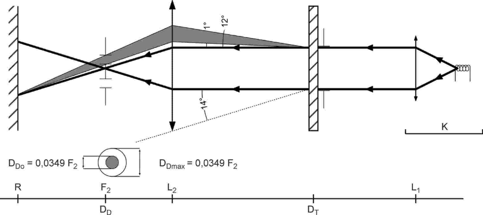
2. MEASUREMENTS
The following readings shall be taken:
|
Reading |
With sample |
With central part of DD |
Quantity represented |
|
T1 |
No |
No |
Incident flux in initial reading |
|
T2 |
Yes (before test) |
No |
Flux transmitted by the new material in a field of 24 deg |
|
T3 |
Yes (before test) |
No |
Flux transmitted by the tested material in a field of 24 deg |
|
T4 |
Yes (before test) |
Yes |
Flux diffused by the new material |
|
T5 |
Yes (before test) |
Yes |
Flux diffused by the tested material |
ANNEX 6
Appendix 3
SPRAY TESTING METHOD
1. TEST EQUIPMENT
1.1. Spray gun
The spray gun used shall be equipped with a nozzle 1,3 mm in diameter allowing a liquid flow rate of 0,24 ± 0,02 l/minute at an operating pressure of 6,0 bars –0/+0,5 bar.
Under these operation conditions the fan pattern obtained shall be 170 mm ± 50 mm in diameter on the surface exposed to deterioration, at a distance of 380 mm ± 10 mm from the nozzle.
1.2. Test mixture
The test mixture shall be composed of:
Silica sand of hardness 7 on the Mohr scale, with a grain size between 0 and 0,2 mm and an almost normal distribution, with an angular factor of 1,8 to 2;
Water of hardness not exceeding 205 g/m3 for a mixture comprising 25 g of sand per litre of water.
2. TEST
The outer surface of the lamp lenses shall be subjected once or more than once to the action of the sand jet produced as described above. The jet shall be sprayed almost perpendicular to the surface to be tested.
The deterioration shall be checked by means of one or more samples of glass placed as a reference near the lenses to be tested. The mixture shall be sprayed until the variation in the diffusion of light on the sample or samples measured by the method described in Appendix 2, is such that: Δd = (T5 – T4) / T2 = 0,0250 ± 0,0025.
Several reference samples may be used to check that the whole surface to be tested has deteriorated homogeneously.
ANNEX 6
Appendix 4
ADHESIVE TAPE ADHERENCE TEST
1. PURPOSE
This method allows to determine under standard conditions the linear force of adhesion of an adhesive tape to a glass plate.
2. PRINCIPLE
Measurement of the force necessary to unstick an adhesive tape from a glass plate at an angle of 90 deg.
3. SPECIFIED ATMOSPHERIC CONDITIONS
The ambient conditions shall be at 23 οC ± 5 οC and 65 ± 15 per cent relative humidity.
4. TEST PIECES
Before the test, the sample roll of adhesive tape shall be conditioned for 24 hours in the specified atmosphere (see paragraph 3. above).
Five test pieces each 400 mm long shall be tested from each roll. These test pieces shall be taken from the roll after the first three turns were discarded.
5. PROCEDURE
The test shall be under the ambient conditions specified in paragraph 3.
Take the five test pieces while unrolling the tape radially at a speed of approximately 300 mm/s, then apply them within 15 seconds in the following manner:
Apply the tape to the glass plate progressively with a slight length- wise rubbing movement of the finger, without excessive pressure, in such a manner as to leave no air bubble between the tape and the glass plate.
Leave the assembly in the specified atmospheric conditions for 10 minutes.
Unstick about 25 mm of the test piece from the plate in a plane perpendicular to the axis of the test piece.
Fix the plate and fold back the free end of the tape at 90 deg. Apply force in such a manner that the separation line between the tape and the plate is perpendicular to this force and perpendicular to the plate.
Pull to unstick at a speed of 300 mm/s ± 30 mm/s and record the force required.
6. RESULTS
The five values obtained shall be arranged in order and the median value taken as a result of the measurement. This value shall be expressed in Newton per centimetre of width of the tape.
ANNEX 7
MINIMUM REQUIREMENTS FOR SAMPLING BY AN INSPECTOR
1. GENERAL
1.1. The conformity requirements shall be considered satisfied from a mechanical and a geometrical standpoint, if the differences do not exceed inevitable manufacturing deviations within the requirements of this Regulation. This condition also applies to colour.
With respect to photometric performances, the conformity of mass- produced systems shall not be contested if, when testing photometric performances of any system chosen at random and equipped with a light source energized, and if applicable corrected, as prescribed in paragraphs 1. and 2. of Annex 9 to this Regulation.
No value deviates unfavourably by more than 20 per cent from the value prescribed in this Regulation;
1.2.1.1. For the following values of the passing beam and its modes, the maximum unfavourable deviation may be respectively:
|
— |
maximum values at point B50L 0,2 lx equivalent 20 per cent and 0,3 lx equivalent 30 per cent; |
|
— |
maximum values at zone III, HV and segment BLL: 0,3 lx equivalent 20 per cent and 0,45 lx equivalent 30 per cent; |
|
— |
maximum values at segments E, F1, F2 and F3: 0,2 lx equivalent 20 per cent and 0,3 lx equivalent 30 per cent; |
|
— |
minimum values at BR, P, S50, S50LL, S50RR, S100, S100LL, S100RR, and those required by footnote 4 of Table 1 in Annex 3 of this Regulation (B50L, HV, BR, BRR, BLL): half of the required value is equivalent to 20 per cent and three quarters of the required value equivalent to 30 per cent; |
1.2.1.2. for the driving beam, HV being situated within the isolux 0,75 Emax, a tolerance of + 20 per cent for maximum values and –20 per cent for minimum values is observed for the photometric values at any measuring point specified in paragraph 6.3.2. of this Regulation.
1.2.2. If the results of the test described above do not meet the requirements, the alignment of the system may be changed, provided that the axis of the beam is not displaced laterally by more than 0,5 deg to the right or left and not by more than 0,2 deg up and down. These provisions do not apply to lighting units as indicated under paragraph 6.3.1.1. of this Regulation.
1.2.3. If the results of the tests described above do not meet the requirements, tests shall be repeated using another standard (étalon) light source and/or another supply and operating device.
1.2.4. Systems with apparent defects are disregarded.
1.2.5. The reference mark is disregarded.
2. FIRST SAMPLING
In the first sampling four systems are selected at random. The first sample of two is marked A, the second sample of two is marked B.
2.1. The conformity is not contested
Following the sampling procedure shown in Figure 1 of this annex the conformity of mass-produced systems shall not be contested if the deviations of the measured values of the systems in the unfavourable directions are:
2.1.1.1. Sample A
|
A1: |
one system |
|
0 per cent |
|
|
one system |
not more than |
20 per cent |
|
A2: |
both systems |
more than |
0 per cent |
|
|
|
but not more than |
20 per cent |
|
|
go to sample B |
|
|
2.1.1.2. Sample B
|
B1: |
both systems |
0 per cent |
2.1.2. or if the conditions of paragraph 1.2.2. for sample A are fulfilled.
2.2. The conformity is contested
Following the sampling procedure shown in Figure 1 of this annex the conformity of mass-produced systems shall be contested and the manufacturer requested to make his production meet the requirements (alignment) if the deviations of the measured values of the systems are:
2.2.1.1. Sample A
|
A3: |
one system |
not more than |
20 per cent |
|
|
one system |
more than |
20 per cent |
|
|
|
but not more than |
30 per cent |
2.2.1.2. Sample B
|
B2: |
in the case of A2 |
|
|
|
|
one system |
more than |
0 per cent |
|
|
|
but not more than |
20 per cent |
|
|
one system |
not more than |
20 per cent |
|
B3: |
in the case of A2 |
|
|
|
|
one system |
|
0 per cent |
|
|
one system |
more than |
20 per cent |
|
|
|
but not more than |
30 per cent |
2.2.2. or if the conditions of paragraph 1.2.2. for sample A are not fulfilled.
2.3. Approval withdrawn
Conformity shall be contested and paragraph 10. applied if, following the sampling procedure shown in Figure 1 of this annex, the deviations of the measured values of the systems are:
2.3.1. Sample A
|
A4: |
one system |
not more than |
20 per cent |
|
|
one system |
more than |
30 per cent |
|
A5: |
Both systems |
more than |
20 per cent |
2.3.2. Sample B
|
B4: |
in the case of A2 |
|
|
|
|
one system |
more than |
0 per cent |
|
|
|
but not more than |
20 per cent |
|
|
one system |
more than |
20 per cent |
|
B5: |
in the case of A2 |
|
|
|
|
both systems |
more than |
20 per cent |
|
B6: |
in the case of A2 |
|
|
|
|
one system |
|
0 per cent |
|
|
one system |
more than |
30 per cent |
2.3.3. or if the conditions of paragraph 1.2.2. for samples A and B are not fulfilled.
3. REPEATED SAMPLING
In the case of A3, B2, B3 a repeated sampling, third sample C of two systems, selected from stock manufactured after alignment, is necessary within two months' time after the notification.
3.1. The conformity is not contested
Following the sampling procedure shown in Figure 1 of this annex the conformity of mass-produced shall not be contested if the deviations of the measured values of the are:
3.1.1.1. Sample C
|
C1: |
one system |
|
0 per cent |
|
|
one system |
not more than |
20 per cent |
|
C2: |
both systems |
more than |
0 per cent |
|
|
|
but not more than |
20 per cent |
|
|
go to sample D |
|
|
3.1.1.2. Sample D
|
D1: |
in the case of C2 |
|
|
|
both systems |
0 per cent |
3.1.2. or if the conditions of paragraph 1.2.2. for sample C are fulfilled.
3.2. The conformity is contested
Following the sampling procedure shown in Figure 1 of this annex the conformity of mass-produced systems shall be contested and the manufacturer requested to make his production meet the requirements (alignment) if the deviations of the measured values of the systems are:
3.2.1.1. Sample D
|
D2: |
in the case of C2 |
|
|
|
|
one system |
more than |
0 per cent |
|
|
|
but not more than |
20 per cent |
|
|
one system |
not more than |
20 per cent |
3.2.1.2. or if the conditions of paragraph 1.2.2 for sample C are not fulfilled.
3.3. Approval withdrawn
Conformity shall be contested and paragraph 10. applied if, following the sampling procedure shown in Figure 1 of this annex, the deviations of the measured values of the systems are:
3.3.1. Sample C
|
C3: |
one system |
not more than |
20 per cent |
|
|
one system |
more than |
20 per cent |
|
C4: |
both systems |
more than |
20 per cent |
3.3.2. Sample D
|
D3: |
in the case of C2 |
|
|
|
|
one system |
|
0 per cent |
|
|
|
or more than |
0 per cent |
|
|
one system |
more than |
20 per cent |
3.3.3. or if the conditions of paragraph 1.2.2. for samples C and D are not fulfilled.
4. CHANGE OF THE VERTICAL POSITION OF THE CUT-OFF LINE FOR PASSING BEAM
With respect to the verification of the change in vertical position of the cut-off line for passing beam under the influence of heat, the following procedure shall be applied:
|
|
One of the systems of sample A after sampling procedure in Figure 1 of this annex shall be tested according to the procedure described in paragraph 2.1. of Annex 4 after being subjected three consecutive times to the cycle described in paragraph 2.2.2. of Annex 4. |
|
|
The system shall be considered as acceptable if Δr does not exceed 1,5 mrad. |
|
|
If this value exceeds 1,5 mrad but is not more than 2,0 mrad, the second system of sample A shall be subjected to the test after which the mean of the absolute values recorded on both samples shall not exceed 1,5 mrad. |
|
|
However, if this value of 1,5 mrad on sample A is not complied with, the two systems of sample B shall be subjected to the same procedure and the value of Δr for each of them shall not exceed 1,5 mrad. |
Figure 1

Note:‘device’ in this figure means ‘system’.
ANNEX 8
PASSING BEAM ‘CUT-OFF’ AND AIMING PROVISIONS (30)
1. CUT-OFF DEFINITION
The ‘cut-off’, when projected on the aiming screen as defined in Annex 9 to this Regulation, shall be sufficiently sharp to permit aiming; it shall comply with the following requirements.
Shape (see Fig. A.8-1)
The ‘cut-off’ shall provide
|
— |
a horizontal ‘flat part’ towards the left, and |
|
— |
a raised ‘shoulder part’ to the right; |
in addition it shall be such, that after being aimed in accordance with the provisions in paragraphs 2.1. to 2.5. below:
1.1.1. The ‘flat part’ shall not deviate vertically by more than
|
— |
0,2 deg up or down from its horizontal median line within 0,5 deg and 4,5 deg left of V-V, and |
|
— |
0,1 deg up or down within two thirds of said length. |
1.1.2. The raised ‘shoulder part’
|
— |
shall have a sufficiently defined left edge, and |
|
— |
the line whose origin is at the intersection of line A and the V-V line to be constructed as a tangent to this edge, shall have an inclination versus the line H-H of at least 10 deg and not exceeding 60 deg (see Fig. A.8-1 below). |
2. VISUAL AIMING PROCEDURE
2.1. The system shall, prior to the subsequent test procedures, be set to the neutral state.
The instructions below apply to the beams of those lighting units, which are specified by the applicant to be aimed.
2.2. The beam shall be vertically positioned so, that the ‘flat part’ of its ‘cut-off’ is situated at the nominal vertical position (line A) according to the respective requirements indicated in Table 2 of Annex 3 to this Regulation; this shall be deemed to be fulfilled, if the horizontal median line of the ‘flat part’ of the ‘cut-off’ is situated at line A (see Fig. A.8-2 below);
The beam shall be horizontally positioned so that its raised ‘shoulder’ is situated to the right of the V-V line and touching it (see Fig. A.8-2 below);
2.3.1. if a partial beam provides a horizontal ‘cut-off’ only: no special requirements for horizontal adjustment apply if not specified by the applicant.
2.4. Any ‘Cut-off’ of a lighting unit not designed to be separately aimed according to the applicant's specification must comply with the relevant requirements.
2.5. Lighting units when aimed using a method specified by the applicant in accordance with the provisions of the paragraphs 5.2. and 6.2.1.1. of this Regulation: the shape and position of the ‘cut-off’, if any, shall comply with the respective requirements of Table 2 of Annex 3 to this Regulation.
2.6. For each further mode of passing beam. The shape and position of the ‘cut-off’, if any, shall comply automatically with the respective requirements of Table 2 of Annex 3. to this Regulation.
2.7. A separate initial aiming and/or adjustment process according to the applicant's specification, based on the provisions of paragraphs 2.1. through 2.6. above, may apply to lighting units intended to be installed separately.
Figures


Note: The ‘cut-off’ is shown schematically, projected on the aiming screen.
ANNEX 9
PHOTOMETRIC MEASUREMENT PROVISIONS
1. GENERAL PROVISIONS
1.1. The system or part(s) thereof shall be mounted on a goniometer with a fixed horizontal axis and moveable axis perpendicular to the fixed horizontal axis.
1.2. The illuminance values shall be determined by means of a photoreceptor contained within a square of 65 mm side and set up to a distance of at least 25 m forward of the centre of reference of each lighting unit perpendicular to the measurement axis from the origin of the goniometer;
1.3. During photometric measurements, stray reflections should be avoided by appropriate masking.
1.4. The luminous intensities are measured and specified in form of illuminance values perpendicular to the direction of measurement, and, for a nominal distance of 25 m.
1.5. The angular co-ordinates are specified in deg on a sphere with a vertical polar axis according to CIE publication No 70, Vienna 1987, i.e. corresponding to a goniometer with a horizontal (‘elevation’) axis fixed to the ground and a second, moveable (‘rotation’) axis perpendicular to the fixed horizontal axis.
1.6. Any equivalent photometric method is acceptable, if the accordingly applicable correlation is observed.
1.7. Any offset of the centre of reference of each lighting unit, with respect to the goniometer rotation axes, should be avoided. This applies especially to the vertical direction and to lighting units producing a ‘cut-off’.
An aiming screen shall be used and may be located at a shorter distance than that of the photoreceptor.
The photometric requirements for each single measuring point (angular position) of a lighting function or mode as specified in this Regulation apply to half of the sum of the respective measured values from all lighting units of the system applied for this function or mode, or, from all lighting units as indicated in the respective requirement;
1.8.1. However in those cases where a provision is specified for one side only, the division by the factor of 2 does not apply. These cases are: paragraphs 6.2.9.1., 6.3.2.1.2., 6.3.2.1.3., 6.4.6., and note 4 of Table 1 of Annex 3.
1.9. The lighting units of the system shall be measured individually;
however, simultaneous measurements may be performed on two or more lighting units of an installation unit, being equipped with the same light source types with respect to their power supply (either power controlled or not), if they are sized and situated such that their illuminating surfaces are completely contained in a rectangle of not more than 300 mm in horizontal extend and not more than 150 mm vertical extend, and, if a common centre of reference is specified by the manufacturer.
1.10. The system shall prior to the subsequent test procedures be set to the neutral state.
1.11. The system or part(s) thereof shall be so aimed before starting the measurements that the position of the ‘cut–off’ complies with the requirements indicated in the Table 2 of Annex 3 to this Regulation. Parts of a system measured individually and having no ‘cut-off’ shall be installed on the goniometer under the conditions (mounting position) specified by the applicant.
2. MEASUREMENT CONDITIONS WITH RESPECT TO LIGHT SOURCES
2.1. In the case of replaceable filament lamps operated directly under vehicle voltage system conditions:
The system or parts thereof shall be checked by means of an uncoloured standard (étalon) filament lamp(s) designed for a rated voltage of 12 V. During checking of the system or part of, the voltage at the terminals of the filament lamp(s) shall be regulated so as to obtain the reference luminous flux as indicated at the relevant data sheet of Regulation No 37.
The system or parts thereof shall be considered acceptable if the requirements of paragraph 6. of this Regulation are met with at least one standard (étalon) filament lamp, which may be submitted with the system.
2.2. In the case of a replaceable gas-discharge light source:
The system or parts thereof using a replaceable gas-discharge light source shall comply with the photometric requirements set out in the relevant paragraphs of this Regulation with at least one standard (étalon) light source, which has been aged during at least 15 cycles, as specified in Regulation No 99. The luminous flux of this gas-discharge light source may differ from the objective luminous flux specified in Regulation No 99.
In this case, the measured photometric values shall be corrected accordingly. They shall be multiplied by a factor of 0.7 prior to the check for compliance.
2.3. In the case of a non-replaceable light source operating directly under vehicle voltage system conditions:
All measurements on lamps equipped with non-replaceable light sources (filament lamps and other) shall be made at 6,75 V, 13,5 V or 28,0 V, or at a voltage as specified by the applicant with respect to any other vehicle voltage system. The measured photometric values shall be multiplied by a factor of 0,7 prior to the check for compliance.
2.4. In the case of a light source, replaceable or non-replaceable, which is operated independently from vehicle supply voltage and fully controlled by the system, or in the case of a light source supplied by a special power supply, the test voltage as specified in paragraph 2.3. above shall be applied to the input terminals of that system/power supply. The test laboratory may require from the manufacturer this special power supply needed to supply the light sources.
The measured photometric values shall be multiplied by a factor of 0,7 prior to the check for compliance, except if this correction factor is already applied according to the provisions of paragraph 2.2. above.
3. MEASUREMENT CONDITIONS WITH RESPECT TO BENDING MODES
In the case of a system or part(s) thereof, which provide a bending mode, the requirements of paragraphs 6.2. (passing beam), and/or 6.3. (driving beam) of this Regulation apply for all states, corresponding to the turn radius of the vehicle. For verification with respect to the passing beam and the driving beam the following procedure shall be used:
The system shall be tested in the neutral state (central/straight), and, in addition in the state(s) corresponding to the smallest turn radius of the vehicle in both directions using the signal generator, if applicable.
3.1.1.1. Compliance with the requirements of paragraphs 6.2.6.2., 6.2.6.3. and 6.2.6.5.1. of this Regulation shall be checked for both category 1 and category 2 bending modes without additional horizontal re-aim.
3.1.1.2. Compliance with the requirements of paragraphs 6.2.6.1. and 6.3. of this Regulation, whichever applies, shall be checked:
|
— |
in case of a category 2 bending mode: without additional horizontal re-aim; |
|
— |
in case of a category 1 or a driving beam bending mode: after having horizontally re-aimed the relevant installation unit (by means of the goniometer for example) in the corresponding opposite direction. |
3.1.2. When testing a category 1 or category 2 bending mode, for a turn radius of the vehicle other than specified in paragraph 3.1.1. above: it shall be observed whether the light distribution is substantially uniform and no undue glare occurs. If this can not be confirmed the compliance with the requirements laid down in Table 1 of Annex 3 to this Regulation shall be checked.
ANNEX 10
DESCRIPTION FORMS
maximum format: A4 (210 × 297 mm)
ADAPTIVE FRONT-LIGHTING SYSTEM DESCRIPTION FORM No 1
AFS control signals relevant to the lighting functions, and modes of functions provided by the system
|
AFS Control Signal |
Function/mode(s) of, being influenced by the signal (31) |
Technical characteristics (32) (use separate sheet, if needed) |
||||
|
Passing beam |
Driving beam |
|||||
|
Class C |
Class V |
Class E |
Class W |
|||
|
None/default |
|
|
|
|
|
|
|
V-Signal |
|
|
|
|
|
|
|
E-Signal |
|
|
|
|
|
|
|
W-Signal |
|
|
|
|
|
|
|
T-Signal |
|
|
|
|
|
|
|
Other Signals (33) |
|
|
|
|
|
|
ADAPTIVE FRONT-LIGHTING SYSTEM DESCRIPTION FORM No 2
Cut-off status, adjustment devices and adjustment procedures relevant to the lighting units
|
Lighting unit No (34) |
Cut-off status (35) |
Adjustment device |
Characteristics & additional provisions (if any) (38) |
||||
|
The lighting unit provides or contributes to one or more passing beam cut-off(s), |
vertical |
horizontal |
|||||
|
as defined in Annex 8 of this Regulation (36) |
and provisions of paragraph 6.4.6. of this Regulation apply (36) |
linked to ‘master’ unit No (37) |
linked to ‘master’ unit No (37) |
||||
|
1 |
yes/no |
yes/no |
yes/no |
… |
Yes/no |
… |
|
|
2 |
yes/no |
yes/no |
yes/no |
… |
Yes/no |
… |
|
|
3 |
yes/no |
yes/no |
yes/no |
… |
Yes/no |
… |
|
|
4 |
yes/no |
yes/no |
yes/no |
… |
Yes/no |
… |
|
|
5 |
yes/no |
yes/no |
yes/no |
… |
Yes/no |
… |
|
|
6 |
yes/no |
yes/no |
yes/no |
… |
Yes/no |
… |
|
|
7 |
yes/no |
yes/no |
yes/no |
… |
Yes/no |
… |
|
(1) For explanation only. The provisions of the passing beam classes are dedicated to conditions as follows: C for the basic passing beam, V for use in lit areas such as towns, E for use on roads such as motorways, W for use in adverse conditions such as wet road.
(2) To be indicated in a form conforming to the model of Annex 1.
(3) To be indicated in a form conforming to the model of Annex 10.
(4) 1 for Germany, 2 for France, 3 for Italy, 4 for the Netherlands, 5 for Sweden, 6 for Belgium, 7 for Hungary, 8 for the Czech Republic, 9 for Spain, 10 for Yugoslavia, 11 for the United Kingdom, 12 for Austria, 13 for Luxembourg, 14 for Switzerland, 15 (vacant), 16 for Norway, 17 for Finland, 18 for Denmark, 19 for Romania, 20 for Poland, 21 for Portugal, 22 for the Russian Federation, 23 for Greece, 24 for Ireland, 25 for Croatia, 26 for Slovenia, 27 for Slovakia, 28 for Belarus, 29 for Estonia, 30 (vacant), 31 for Bosnia and Herzegovina, 32 for Latvia, 33 (vacant), 34 for Bulgaria, 35-36 (vacant), 37 for Turkey, 38-39 (vacant), 40 for The former Yugoslav Republic of Macedonia, 41 (vacant), 42 for the European Community (Approvals are granted by its Member States using their respective ECE symbol), 43 for Japan, 44 (vacant), 45 for Australia, 46 for Ukraine, 47 for South Africa, 48 for New Zealand, 49 for Cyprus, 50 for Malta and 51 for the Republic of Korea. Subsequent numbers shall be assigned to other countries in the chronological order in which they ratify or accede to the Agreement concerning the Adoption of Uniform Technical Prescriptions for Wheeled Vehicles, Equipment and Parts which can be Fitted and/or be Used on Wheeled Vehicles and the Conditions for Reciprocal Recognition of Approvals Granted on the Basis of these Prescriptions, and the numbers thus assigned shall be communicated by the Secretary-General of the United Nations to the Contracting Parties to the Agreement.
(5) Note: measurement procedure prescribed in Annex 9 to this Regulation.
(6) Max 18 lx, if the system is designed to provide also a class W passing beam.
(7) Requirements according to the provisions indicated in Table 4 below apply in addition.
(8) Position requirements according to the provisions of Table 2 below (‘Segment Emax’).
(9) The contribution of each side of the system, when measured according to the provisions of Annex 9 to this Regulation shall not be less than 0,1 lx.
(10) Position requirements according to the provisions of Table 5 below.
(11) Position requirements as indicated in paragraph 6.2.6.2. of this Regulation.
(12) One pair of position lamps, being incorporated with the system or being intended to be installed together with the system may be activated according to the indications of the applicant.
(13) Requirements according to the provisions indicated in Table 6 below apply in addition.
(14) Requirements according to the provisions indicated in Table 6 below apply in addition.
(15) Max 11 250 cd, if the system is designed to provide also a class W passing beam.
(16) Requirements according to the provisions indicated in Table 4 below apply in addition.
(17) Position requirements according to the provisions of Table 2 below (‘Segment Emax’).
(18) The contribution of each side of the system, when measured according to the provisions of Annex 9 to this Regulation shall not be less than 63 cd.
(19) Position requirements according to the provisions of Table 5 below.
(20) Position requirements as indicated in paragraph 6.2.6.2. of this Regulation.
(21) One pair of position lamps, being incorporated with the system or being intended to be installed together with the system may be activated according to the indications of the applicant.
(22) Requirements according to the provisions indicated in Table 6 below apply in addition.
(23) When the ‘test sample’ is grouped and/or reciprocally incorporated with signalling lamps, the latter shall be lit for the duration of the test. In the case of a direction indicator lamp, it shall be lit in flashing operation mode with an on/off time ratio of approximately one to one.
(24) Should additional light sources be simultaneously lit when headlamp flashing is used, this shall not be considered as being normal use of the light sources simultaneously.
(25) All light sources of lighting functions even if no approval is sought according to this Regulation must be taken into account, except those covered by footnote 2.
(26) The class W passing beam, if any, is disregarded for lighting units providing or contributing to any other passing beam class or lighting function.
(27) NaCMC represents the sodium salt of carboxymethylcellulose, customarily referred to as CMC. The NaCMC used in the dirt mixture shall have a degree of substitution (DS) of 0,6-0,7 and a viscosity of 200-300 cP for a 2 per cent solution at 20 °C.
(28) When the driving beam is reciprocally incorporated with the passing beam, HV in the case of the driving beam shall be the same measuring point as in the case of the passing beam.
(29) ‘HL’ and ‘HR’: points on ‘H-H’ located at 2,6 deg to the left and to the right of point HV respectively.
(30) Optionally to be completed by additional general provisions under study in GRE.
(31) Mark in the respective box(es) with an cross (X) the combination(s) which apply.
(32) To be indicated in terms of:
|
— |
physical nature (electrical current/voltage, optical, mechanical, hydraulic, pneumatic, …), |
|
— |
information type (continuous/analogous, binary, digitally coded, …), |
|
— |
time dependent properties (time constant, resolution, …), |
|
— |
signal status when the respective conditions according to paragraph 6.22.7.4. of Regulation No 48 are fulfilled, |
|
— |
signal status in case of failure (with reference to the system input). |
(33) According to the applicants description; use separate sheet, if needed.
(34) Designation of each individual lighting unit of the system as indicated in Annex 1 to this Regulation and as shown in the drawing according to paragraph 2.2.1. of this Regulation; use separate sheet(s) if needed.
(35) Relevant to provisions of paragraph 6.22.6.1.2. of Regulation No 48.
(36) Strike out what does not apply.
(37) Indicate corresponding lighting unit(s) number(s), if applicable.
(38) Information such as e.g.: the order of adjustment of lighting units or assemblies of lighting units, any additional provisions for the adjustment process.
(39) The adjustment of a ‘master’ lighting unit may also adjust (an)other lighting unit(s).
|
9.3.2007 |
EN |
Official Journal of the European Union |
L 70/413 |
Corrigendum to Regulation No 124 of the Economic Commission for Europe of the United Nations (UN/ECE) — Uniform provisions concerning the approval of wheels for passenger cars and their trailers
( Official Journal of the European Union L 375 of 27 December 2006 )
Regulation No 124 should read as follows:
Regulation No 124 of the Economic Commission for Europe of the United Nations (UN/ECE) — Uniform provisions concerning the approval of wheels for passenger cars and their trailers
1. SCOPE
This Regulation covers new replacement wheels designed for vehicles in categories M1, M1G, O1 and O2 (1).
It does not apply to original equipment wheels or vehicle manufacturer's replacement wheels as defined in paragraphs 2.3. and 2.4.1. It does not apply to ‘Special wheels’, as defined in paragraph 2.5., which shall remain subjected to national approval.
This Regulation comprises requirements for wheel manufacture and installation.
2. DEFINITIONS
For the purpose of this Regulation:
‘Wheel’ means a rotating load-carrying member between the tyre and the axle. It usually consists of two major parts:
|
(a) |
the rim; |
|
(b) |
the wheel disc. |
The rim and wheel disc may be integral, permanently attached, or detachable.
2.1.1. ‘Disc wheel’ means a permanent combination of a rim and wheel disc.
2.1.2. ‘Wheel with demountable rim’ means a wheel so constructed that the demountable rim is clamped to the wheel disc.
2.1.3. ‘Rim’ means that part of the wheel on which the tyre is mounted and supported.
2.1.4. ‘Wheel disc’ means that part of the wheel which is the supporting member between the axle and the rim.
‘Wheel type’ means a wheel which does not differ in the following essential characteristics:
2.2.1. the wheel manufacturer;
2.2.2. wheel or rim size designation (according to ISO 3911:1998);
2.2.3. construction materials;
2.2.4. wheel attachment holes;
2.2.5. maximum load capacity;
2.2.6. recommended maximum inflation pressure;
2.2.7. method of production (welded, forged, cast, …).
2.3. ‘OE-wheels’ means wheels which are authorized to be fitted, to the vehicle model, by the vehicle manufacturer during the production of the vehicle.
‘Replacement Wheels’ means wheels which are intended to replace the OE wheels during the service life of the vehicle. Replacement wheels may belong to one of the following category:
2.4.1. ‘Vehicle manufacturer's replacement wheels’ being wheels supplied by the vehicle manufacturer;
2.4.2. ‘Identical replacement wheels’ being wheels which are manufactured using the same manufacturing equipment and material as that used for replacement wheels supplied by the vehicle manufacturer. They differ from vehicle manufacturer's replacement wheels only by the absence of vehicle manufacturer's trademarks and part number;
2.4.3. ‘Replica replacement wheels’ being wheels which are replicas of vehicle manufacturer's replacement wheels but produced by a manufacturer who is not a supplier of the vehicle manufacturer with the specified wheel. With regard to the design (basic contour, dimensions, inset, material type and quality and so on) and service life they fully correspond to vehicle manufacturer's replacement wheels;
2.4.4. ‘Pattern part replacement wheels’ being wheels produced by a manufacturer who is not a supplier of the vehicle manufacturer with the specified wheel. With regard to the design, inset, rim designation wheel fixing PCD and spigot mounting diameter, correspond to that of an OE-wheel, but wheel contour, material and so on, may be different;
2.5. ‘Special wheels’ means wheels which are not OE-wheels and which do not fulfil the criteria for wheels described in paragraph 2.4. (for example wheels with different rim width or diameter).
2.6. ‘Inset’ means the distance from the attachment face of the disc to the centre line of the rim (that can be positive, as shown in Figure 1 below, zero, or negative).
2.7. ‘Dynamic radius’ means the dynamic loaded radius defined as the theoretical rolling circumference divided by 2Π of the largest tyre to be used on the wheel as specified by the wheel manufacturer.
2.8. ‘International Tyre and Rim Standards’ mean documents concerning wheel standardization issued by the following Organizations:
|
(a) |
The International Organization for Standardization (ISO) (2); |
|
(b) |
The European Tyre and Rim Technical Organization (ETRTO) (3): ‘Standards Manual’; |
|
(c) |
The European Tyre and Rim Technical Organization (ETRTO) (3): ‘Engineering Design Information — obsolete data’; |
|
(d) |
The Tyre and Rim Association Inc. (TRA) (4): ‘Year Book’; |
|
(e) |
The Japan Automobile Tyre Manufacturers Association (JATMA) (5): ‘Year Book’; |
|
(f) |
The Tyre and Rim Association of Australia (TRAA) (6): ‘Standard Manual’; |
|
(g) |
The Associação Latino Americana de Pneus e Aros (ALAPA) (7): ‘Manual de Normal Technicas’; |
|
(h) |
The Scandinavian Tyre and Rim Organisation (STRO) (8): ‘Data Book’. |
Figure 1

2.9. ‘Technical crack’ is a material separation with a propagation of more than 1 mm occurring during a dynamic test (defects caused by the production process are not to be taken into account).
2.10. ‘Wheel calliper’ is the rotating profile shape, formed by the internal wheel contour (see Annex 10, figure 1).
2.11. ‘Tyre size designation’ means a designation showing the nominal section width, the nominal aspect ratio and the conventional number that denotes the nominal rim diameter (these terms are further defined in Regulation No 30).
3. APPLICATION FOR APPROVAL
The application for approval of a wheel type shall be submitted by the manufacturer, or by his duly accredited representative, and shall be accompanied by:
3.1.1. Drawings, in triplicate, sufficiently detailed to permit identification of the type. They shall also show the position intended for the approval mark and for the wheel markings;
Technical description including at least the following characteristics:
3.1.2.1. Category of replacement wheels — see paragraphs 2.4.2., 2.4.3. and 2.4.4.;
3.1.2.2. rim contour designation — wheel inset — wheel attachment details;
3.1.2.3. tightening torque for studs and nuts;
3.1.2.4. fixing method of balancing weights;
3.1.2.5. necessary accessories (i.e. additional mounting components);
3.1.2.6. International Standard reference;
3.1.2.7. suitable for tubeless tyre mounting;
3.1.2.8. suitable valves types;
3.1.2.9. maximum load capacity;
3.1.2.10. maximum inflation pressure;
3.1.2.11. detail of material including chemical composition (see Annex 4).
3.1.2.12. tyre size designations specified for original equipment by the vehicle manufacturer.
3.1.3. Documentation in accordance with paragraph 1. of annex 10 to this Regulation:
|
— |
vehicle characteristics (Annex 10, paragraph 1.2.); |
|
— |
additional characteristics (Annex 10, paragraph 1.3.); |
|
— |
fitting instructions details (Annex 10, paragraph 1.4.); and |
|
— |
additional requirements (Annex 10, paragraph 2.). |
3.1.4. Sample wheels representative of the wheel type necessary for the execution of laboratory tests or test reports issued by the Type Approval Authority.
3.2. In case of application for approval of an identical wheel, the applicant shall satisfy the type approval authority that the wheel is indeed an ‘identical replacement wheel’ as defined in paragraph 2.4.2.
4. APPROVAL
4.1. If the wheel submitted for approval in accordance with paragraph 3. above meets the requirements, then approval for this type of wheel shall be granted.
4.2. An approval number shall be assigned to each type approved. The first two digits (at present 00 for the regulation in its original form) shall indicate the series of amendments incorporating the most recent major technical amendments made to the Regulation at the time of issue of the approval. The same Contracting Party may not assign the same number to another type of wheel.
4.3. Notice of approval or refusal or extension of approval of a type of wheel under this regulation shall be communicated to the parties to the 1958 Agreement which apply this regulation by means of a communication form conforming to the model in annex 1 to this Regulation.
Every wheel conforming to a type approved under this regulation shall bear, in addition to the markings prescribed in paragraph 5., a clearly legible and indelible international approval mark consisting of:
4.4.1. circle surrounding the letter E followed by the distinguishing number of the country which has granted approval (see Annex 2) (9).
4.4.2. The number of this Regulation, followed by the letter R, a dash and the approval number according to paragraph 4.2.
4.5. The approval mark shall be permanent, visible and clearly legible, when the tyre is fitted on the wheel.
4.6. Annex 2 to this regulation gives an example of the arrangement of the approval mark.
4.7. The wheel manufacturer's facilities may be used for test purposes provided that the Type Approval Authority or a designated representative witnesses the tests.
5. WHEEL MARKINGS
The wheel shall be permanently and legibly marked as follows, in a position chosen by the manufacturer, but visible when the tyre is fitted on the wheel:
5.1.1. manufacturer name or trade mark;
the wheel or rim contour designation;
5.1.2.1. It shall be expressed according to the prescription of one International Tyre and Rim Standards and includes at least:
|
— |
rim size designation comprising: |
|
— |
rim contour designation nominal rim diameter, |
|
— |
the symbol ‘x’ if one piece rim, |
|
— |
the symbol ‘-’ if multipiece rim |
|
— |
letter ‘A’ if the well is located asymmetrically (optional), |
|
— |
the letter ‘S’ if the well is located symmetrically (optional). |
5.1.3. the wheel inset;
5.1.4. date of manufacture(at least the month and year);
5.1.5. the wheel/rim part number.
5.2. Annex 3 to this regulation gives an example of the arrangement of the wheel markings.
6. GENERAL REQUIREMENTS
6.1. Rim contour shall conform to the International Standard specified by the wheel manufacturer.
Rim contour shall ensure the correct fitting of tyres and valves.
6.2.1. Wheels designed for use with tubeless tyres shall ensure air retention.
6.3. Materials used for the construction of the wheel shall be analysed according to Annex 4.
6.4. In the case of identical replacement wheel as defined in paragraph 2.4.2., there shall not be any requirement for physical testing as given in paragraph 6.5. or vehicle fitment checking as given in paragraph 2. of Annex 10 to this Regulation.
The replica replacement wheels and pattern part replacement wheels shall satisfy the following tests:
6.5.1. Steel wheels
6.5.1.1. Disc wheels
|
(a) |
rotating bending test as per Annex 6; |
|
(b) |
rolling test as per Annex 7. |
6.5.2. Aluminium alloy wheels
6.5.2.1. One piece wheels
|
(a) |
Corrosion test as per Annex 5. If the process within a production line is always the same, only one representative test is to be carried out; |
|
(b) |
Rotating bending test as per Annex 6; |
|
(c) |
Rolling test as per Annex 7; |
|
(d) |
Impact test as per Annex 8. |
6.5.2.2. Demountable rim wheels
|
(a) |
Corrosion test as per Annex 5; |
|
(b) |
Rotating bending test as per Annex 6; |
|
(c) |
Rolling test as per Annex 7; |
|
(d) |
Impact test as per Annex 8; |
|
(e) |
Alternating torque test as per Annex 9. |
6.5.3. Magnesium alloy wheels
6.5.3.1. One piece wheels
|
(a) |
Corrosion test as per Annex 5; |
|
(b) |
Rotating bending test as per Annex 6; |
|
(c) |
Rolling test as per Annex 7; |
|
(d) |
Impact test as per Annex 8. |
6.5.3.2. Demountable rim wheels
|
(a) |
Corrosion test as per Annex 5; |
|
(b) |
Rotating bending test as per Annex 6; |
|
(c) |
Rolling test as per Annex 7; |
|
(d) |
Impact test as per Annex 8; |
|
(e) |
Alternating torque test as per Annex 9. |
6.6. Where a wheel manufacturer submits application for type approval for a range of wheels, it is not considered necessary to carry out all tests on every type of wheels in the range. Worst case selection may be made at the discretion of the type approval Authority or the designated Technical Service (see Annex 6 paragraph 4. of this Regulation).
Pattern part replacement wheels shall satisfy the following requirements to guarantee proper fitment on the vehicle:
6.7.1. The nominal rim diameter, nominal rim width and nominal inset of ECE-approved wheels shall be the same as the manufacturer's replacement wheel.
6.7.2. Wheels shall be suitable for tyres of the tyre size designations specified initially by the vehicle manufacturer for the particular model concerned.
6.7.3. The checks and documentation relevant to the wheel/vehicle fitment are described in Annex 10.
7. MODIFICATIONS AND EXTENSION OF APPROVAL FOR WHEEL
Every modification of the wheel type shall be notified to the approval authority which granted the type approval. The approval authority may then:
7.1.1. either consider that the modifications made are unlikely to have appreciable adverse effects and that in any case the type of wheel still complies with the requirements;
7.1.2. or require a further test.
7.2. Confirmation or refusal of approval, specifying the alterations, shall be notified by the procedure specified in paragraph 4.3. above to the parties to the agreement applying this regulation.
7.3. The competent authority issuing the extension of approval shall assign a series number to each communication form drawn up for such an extension.
8. CONFORMITY OF PRODUCTION
8.1. The conformity of production procedures shall comply with those set out in the Agreement — E/ECE/324-E/ECE/TRANS/505/Rev.2, Appendix 2.
8.2. The authority which has granted type approval may at any time verify the conformity control methods applied in each production facility. The normal frequency of these verifications shall be once every two years.
9. PENALTIES FOR NON-CONFORMITY OF PRODUCTION
9.1. The approval granted in respect of a type of wheel pursuant to this regulation may be withdrawn if the requirements set forth above are not met or if a wheel bearing the approval mark does not conform to the type approved.
9.2. If a Contracting Party to the Agreement applying this regulation withdraws an approval it has previously granted, it shall forthwith so notify the other Contracting Parties applying this regulation, by means of a communication form conforming to the model in Annex 1 to this Regulation.
10. PRODUCTION DEFINITELY DISCONTINUED
If the holder of an approval completely ceases to manufacture a wheel approved in accordance with this regulation, he shall so inform the authority which granted the approval. Upon receiving the relevant communication, that authority shall inform the other parties applying this regulation by means of a communication form conforming to the model in Annex 1 to this Regulation.
11. NAMES AND ADDRESSES OF TECHNICAL SERVICES RESPONSIBLE FOR CONDUCTING APPROVAL TESTS AND OF ADMINISTRATIVE DEPARTMENTS
The Contracting Parties to the Agreement applying the regulation shall communicate to the United Nations secretariat the names and addresses of the Technical Services responsible for conducting approval tests and of the administrative departments which grant approval and to which forms certifying approval or extension or refusal or withdrawal of approval, or production definitely discontinued issued in other countries, are to be sent.
ANNEX 1

ANNEX 2
ARRANGEMENT OF THE APPROVAL MARK

The wheel bearing the above approval mark is a wheel that has been approved in Italy (E3) under approval number 001148.
The first two digits of the approval number indicate that the approval was granted in accordance with the requirements of Regulation No XY in its original form.
The marking of approval mark, the Regulation number and approval number may be at a distance from each other respecting the sequence.
ANNEX 3
ARRANGEMENT OF THE WHEEL MARKINGS
Example of markings which shall be applied to a wheel conforming to this Regulation:
|
ABCDE |
5
|
36 |
01 99 |
ab123 |
This example of marking defines a wheel:
|
— |
manufactured by ABCDE |
|
— |
having a rim contour designation (5 |
|
— |
having a one piece construction (x) |
|
— |
having a nominal rim diameter code (14) |
|
— |
having a non symmetrical location of the well (no mark) |
|
— |
having a flat hump configuration of the bead-seat area on one side only (FH) – optional marking |
|
— |
having a wheel inset of 36 mm |
|
— |
manufactured in January 1999 (0199) |
|
— |
the manufacturer's part number (ab123). |
The rim designation shall include in the following order the rim contour designation, the construction, the nominal rim diameter code, the location of the well and the bead-seat configuration, as in the example 5 ![]() J x 14 FH. It is also permitted to reverse the order for the first three elements as in the example 14 x 5
J x 14 FH. It is also permitted to reverse the order for the first three elements as in the example 14 x 5 ![]() J FH.
J FH.
The marking of the wheel inset, the date of production and manufacturer's name may be at a distance from the rim designation.
ANNEX 4
MATERIAL TEST
The following metallurgical analysis shall carried out and reported:
|
Material |
Tests |
|
Aluminium alloy |
a, c, e |
|
Magnesium alloy |
a, c, e |
|
Steel |
a, b, d |
|
(a) |
Chemical analysis of the raw-material. |
|
(b) |
Check of the following mechanical characteristics (R p0,2, R m, and A) relevant to the materials:
|
|
(c) |
Check of the mechanical characteristics (R p0,2, R m, and A) of test-pieces taken from the hub mounting area and in the disc to rim transition area or in the failure zone if any. |
|
(d) |
Analysis of the metallurgic defects and of the raw material structure. |
|
(e) |
Analysis of the metallurgic defects and of the test-pieces structure taken from the hub mounting area and in the disc to rim transition area or in the failure zone if any. |
ANNEX 5
CORROSION TEST
Carry out a salt-spray test as per ISO 9227 for 384 hours.
1.1. Sample preparation
A surface treated sample, taken from production, shall be damaged by cross engraving and stone impact (ISO 565) to represent damaging situations during the normal usage of vehicle (damage shall be in the area of the rim flange and inside the wheel).
1.2. Test development
The surface treated sample shall pass a salt-spray test, in which the sample and any components with which is normally in contact are put in upright position into the salt-spray test equipment. The wheel is turned through 90° every 48 hours.
1.3. Evaluation
Individual measures which may affect the corrosion are to be evaluated (covers, crews, zinc or cadmium buses, alloy insulating covers, etc.)
The test documentation shall include photos showing the main corrosion points which have been mechanically washed in order to show the material defects.
There shall not be any significant corrosion after a test duration of 192 hours. After 384 hours the wheel functionality, the mounting components and the tyre bead seat shall not be adversely affected by corrosion. This shall be confirmed by a rotating bending test as per Annex 6 or by a rolling test as per Annex 7, depending on the location of the corrosion.
ANNEX 6
ROTATING BENDING TEST
1. TEST DESCRIPTION
During the rotating bending test, the lateral forces acting on wheel in driving around a curve are simulated. Four wheel samples shall be tested, two at 50 % and two at 75 % of the maximum side force. The wheel rim is fixed rigidly to the test bench, and a bending moment Mb is applied to the hub mounting area (i.e. through a loading arm with a flange having the same pitch circle diameter as the vehicle for which the wheel is intended). Light alloy wheels are fixed using the internal rim flange by two semicircular flanges.
Should other fixing devices be used, it is necessary prove their equivalence.
Screws or fixing nuts are tightened to the torque stated by the vehicle manufacturer and retightened after 10 000 cycles approximately.
2. FORMULA FOR THE BENDING MOMENT CALCULATION
Cars and off-road vehicles: Mbmax = S × FV (μ × rdyn + d)
|
Mbmax |
= |
maximum reference bending moment [Nm] |
|
FV |
= |
maximum load capacity of wheel [N] |
|
rdyn |
= |
dynamic radius of largest tyre recommended for wheel [m] |
|
d |
= |
inset [m] |
|
μ |
= |
coefficient of friction |
|
S |
= |
factor of safety |
3. The test is carried out with two percentage values (50 per cent and 75 per cent) of the max moment and on the basis of the following standards
|
Coefficient of friction |
0,9 |
|
Factor of safety |
2,0 |
|
Nominal cycles per minute |
The number of cycles per minute can be the maximum possible but outside the testing rig resonance frequency |
|
|
Aluminium/Magnesium |
Steel |
||
|
Vehicle category |
M1 and M1G |
O1 and O2 |
M1 and M1G |
O1 and O2 |
|
Min cycles with 75 per cent Mbmax |
2,0 · 105 |
0,66 · 105 |
6,0 · 104 |
2,0 · 104 |
|
Min cycles with 50 per cent Mbmax |
1,8 · 106 |
0,69 · 106 |
6,0 · 105 |
2,3 · 105 |
|
Acceptance limits |
Shaft displacement less than 10 per cent greater than the displacement measured after approximately 10 000 cycles. |
|||
|
Technical cracks are not accepted. |
— |
|||
|
Allowable loss of tightening torque initially applied to the wheel fixing studs and nuts (10) |
Maximum 30 per cent |
|||
4. TEST SCHEDULE FOR RANGE OF WHEEL TYPES
Wheels of the same type (paragraph 2.2.) but with different inset values can be grouped using the highest value of test bending moment according to the following test schedule. Wheel versions having a larger centre hole shall be included in the test. In the case of a failure further samples shall be tested.
Necessary tests:
|
Number of wheels to be tested |
Rotating bending test |
|
|
|
Short test |
Long test |
|
Minimum PCD Maximum PCD if only one PCD |
1 1 2 |
1 1 2 |
|
Inset variations up to 2 mm From 2 mm to 5 mm > 5 mm |
— 1 1 |
— — 1 |
Tests to be carried out should the maximum permitted wheel load subsequently increase.
|
If the resulting test bending moment increases up to 10 per cent max. |
1 |
1 |
|
Short test |
= |
rotating bending test with 75 per cent of l Mbmax (calculated for the max wheel load) |
|
Long test |
= |
rotating bending test with 50 per cent of Mbmax |
Should the testing moment be increased of more of 10 per cent, when compared to the first approval, the whole programme shall be repeated.

ANNEX 7
ROLLING TEST
1. TEST DESCRIPTION
In the rolling test the stress on the wheel when driving straight ahead is simulated by testing a wheel rolling against a drum which has a minimum outside diameter of 1,7 m, in the case of an external rolling test, or a minimum internal diameter equal to the dynamic radius of the tyre divided by 0,4 in the case of an internal rolling test. Two wheels shall be tested.
2. FORMULA FOR CALCULATION OF THE TEST LOAD
|
All types of vehicles |
FP = S · FV |
|
FP |
= |
testing load [N] |
|
FV |
= |
wheel maximum load capacity of the wheel [N] |
|
S |
= |
factor of safety |
3. TESTS PROCEDURE AND REQUIREMENTS
Tests are carried out on the basis of the following specifications:
|
|
M1 and M1G |
O1 and O2 |
||
|
Rolling direction |
Straight |
|||
|
Factor of safety — S |
2,5 2,25 (11) |
2,0 |
||
|
Tyres |
Taken from normal (series) production and, if possible, of the maximum nominal section width recommended for the wheel |
|||
|
Testing speed in km/h |
The max. allowed by the tyre given by the speed index, usually 60-100 km/hour |
|||
|
Equivalent rolling distance |
2 000 km 1 000 km (11) |
2 000 km 1 000 km (11) |
||
|
Tyre pressure at start of test (nor checked or controlled during the test) |
Normal usage: |
rolling test pressure |
||
|
Up to |
160 kPa |
280 kPa |
||
|
More than |
160 kPa |
min. 400 kPa |
||
|
Limits of acceptance |
Technical cracks and/or air leakage are not accepted. |
|||
|
Allowable loss of tightening torque initially applied to the wheel fixing studs and nuts (12) |
≤ 30 per cent |
|||

ANNEX 8
IMPACT TEST
1. TEST DESCRIPTION
Wheel strength with regard to the fractures on edges and other critical points when the wheel strikes an obstacle shall be checked. In order to show the sufficient resistance to fractures it is necessary carry out an impact test as per Annex 8 — Appendix 1.
2. FORMULA FOR THE CALCULATION OF TEST LOAD
|
D |
= |
0,6 · FV / g + 180 [kg] |
|
D |
= |
value of falling mass [kg] |
|
FV |
= |
maximum wheel load capacity [N] |
|
g |
= |
acceleration due to gravity 9,81 m/s2 |
3. TEST PROCEDURE AND REQUIREMENTS
|
|
M1 and M1G |
|
Procedure and requirements |
As per Annex 8 — Appendix 1 |
|
Tyre pressure |
The tyre pressure recommended by the tyre manufacturer based on the load index and the max. vehicle speed, but at least 200 kPa. |
|
Tyres |
Tyres taken from normal (series) production with the minimum nominal section width and minimum rolling circumference on the range of tyres recommended for the particular wheel. |
|
Acceptance criteria |
The test shall be considered satisfactory if there is not any visible fracture penetrating through the wheel surface and if there is not any loss of inflation pressure within one minute of completing the test. Fractures and indentations caused by the direct contact with the falling weight are acceptable. In the case of wheels with demountable rims or other components that can be dismantled, if threaded fastenings that are close to the spoke or ventilation holes fail the wheel is to be considered as having failed the test. |
|
Number of samples to be tested |
One for each impact position. |
|
Impact positions |
One in the area connecting spokes to rim and further one in the area between two spokes, very close to the valve hole. If possible, the impact direction shall not coincide with the radial line between a fixing hole and the wheel centre. |
4. TESTS SCHEDULE FOR RANGE OF WHEEL TYPES
Tests necessary:
|
Wheels to be tested |
Impact test |
|
Minimum PCD of fixing holes Maximum PCD of fixing holes |
One for each impact position One for each impact position |
ANNEX 8
Appendix 1
PASSENGER CARS — LIGHT ALLOY WHEELS — IMPACT TEST
1. SCOPE
This annex specifies a laboratory test procedure to evaluate the axial (lateral) kerb impact collision properties of a wheel manufactured either wholly or partly of light alloys. It is intended for passenger car applications, with the purpose of screening and/or quality control of the wheel.
2. TEST EQUIPMENT
2.1. New wheels, fully processed, representative of wheels intended for passenger car application, fitted with a tyre.
2.2. Impact loading test machine with a vertically acting striker having an impacting face at least 125 mm wide and at least 375 mm long and sharp edges broken by radius or chamfer, in accordance with figure 1. The falling mass, D, within a tolerance of ± 2 per cent, expressed in kilograms, shall be as follows:
D = 0,6 · FV / g + 180 [kg]
where FV/g is the maximum static wheel loading, as specified by the wheel and/or vehicle manufacturer, expressed in kilograms.
2.3. Mass of 1 000 kg.
3. CALIBRATION
Ensure, by means of a test calibration adapter, that the 1 000 kg mass (paragraph 2.3.) applied vertically to the centre of the wheel fixing as shown in figure 2 causes a deflection of 7,5 mm ± 0,75 mm when measured at the centre of the beam.
4. TEST PROCEDURE
4.1. Mount the test wheel (paragraph 2.1.) and tyre in the test machine (paragraph 2.2.) such that the impact loading is applied to the rim flange of the wheel. The wheel shall be mounted with its axis at an angle of 13° ± 1° to the vertical with its highest point presented to the striker.
The tyre mounted on the test wheel shall be the smallest nominal section width tubeless radial-ply tyre intended for use on that wheel. The inflation pressure shall be that specified by the vehicle manufacturer or, in the absence of such specification, it shall be 200 kPa.
The temperature of the test environment shall remain within a range of 10 °C to 30 °C throughout the test period.
4.2. Ensure that the wheel is mounted on the hub fixture with dimensionally representative fixings such as would be used on a vehicle. Manually tighten the fixings to a value or by a method as recommended by the vehicle or wheel manufacturer.
Because the design of wheel centre members may vary, test a sufficient number of locations on the wheel rim circumference to ensure that the integrity of the centre members is assessed. Use new wheels each time.
In case of test on the spoke, that spoke is to be chosen where the bolt hole is closest.
4.3. Ensure that the striker is over the tyre, and overlaps the rim flange by 25 mm ± 1 mm. Raise the striker to a height of 230 mm ± 2 mm above the highest part of the rim flange and allow it to fall.
5. FAILURE CRITERIA
The wheel is considered to have failed the test if any of the following apply:
|
(a) |
visible fracture(s) penetrate through a section of the centre member of the wheel assembly; |
|
(b) |
the centre member separates from the rim; |
|
(c) |
the tyre loses all air pressure within 1 min. |
The wheel is not considered to have failed the test by deformation of the wheel assembly or by fractures in the area of the rim section struck by the face plate of the striker.
Note: Tyres and wheels used in the tests should not be used subsequently on a vehicle.


ANNEX 9
ALTERNATING TORQUE TEST
1. TEST DESCRIPTION
In an alternating torque test the torque acting on wheel during braking and acceleration is simulated. The sample wheels shall be tested at each percentage value (50 per cent and 75 per cent) of the maximum calculated torque. Each wheel flange is rigidly fixed on the test table and stressed by an alternating torque of ± MT, introduced through the attachment face i.e. through a brake disc or through other components.
2. FORMULA FOR THE CALCULATION OF THE TEST TORQUE
MT = S · FV · rdyn
Where:
|
MT |
= |
test torque [Nm] |
|
S |
= |
factor of safety |
|
FV |
= |
maximum wheel load capacity [N] |
|
rdyn |
= |
dynamic radius [m] |
Tests are carried out on the basis of the following parameters:
|
Factor of safety S |
1,0 |
|
Min number of cycles with ± 90 per cent MT |
2 · 105 |
|
Min number of cycles with ± 45 per cent MT |
2 · 106 |
|
Acceptance criteria |
Technical cracks not acceptable |
|
Allowable loss of the initial torque applied to wheel fixing studs and nuts (13) |
30 per cent |
ANNEX 10
VEHICLE FITMENT CHECKS AND DOCUMENTATION
1. APPLICATION AND FITTING INFORMATION
The type approval authority shall be supplied with a copy of following information which shall also be supplied to the consumer with the wheel.
1.1. Wheel characteristics:
ECE approval number, wheel type and variant, international rim designation (for example, 15 H2 x 5 ![]() J) and inset.
J) and inset.
1.2. Vehicle characteristics:
Vehicle manufacturer, vehicle model name and description, vehicle power and VIN range including at least WMI, VDS and first digit of VIS describing the model year (see ISO 3779-1983).
1.3. Additional characteristics: Any particular requirements, special fittings and so on that are specified when using the manufacturer's replacement wheels or specific requirements for the ECE approved wheel.
1.4. Fitting instruction detail: Recommendations and safety precautions when fitting the wheel;
Use of any additional or substitute wheel fixing components, for example, longer wheel bolts or studs with alloy wheels;
Wheel fixing tightening torque; drawing attention to the importance of this aspect and the need to preferably use a calibrated torque wrench; Instruction regarding the necessity to re-tighten the wheel fixing after 50 km of driving; References to the use and mounting of hubcaps, if applicable;
1.5. Example of a possible structure of the Application and fitting Information table
Wheel characteristics (mandatory fields in bold characters)
|
ECE approval number |
Wheel type |
Size |
Inset |
Pcd |
Fixing holes (14) |
|
XY R-I 0001148 |
6014 |
6Jx14H2 |
38 mm |
98 mm |
4 |
|
Wheel variant |
Control spigot location |
Wheel marking |
centre ring marking |
Centre hole Dia. |
max. wheel load in N |
|
A |
Yes |
98-38 |
120-98 |
58,1 mm |
5 500 |
Vehicles' characteristics
|
Vehicle manufacturers |
Vehicle model name |
Vehicle type |
Power In kW |
Identification (VIN) |
||
|
FIAT |
ALFA ROMEO 145/146 |
ALFA ROMEO 930 |
66-95 |
WMI |
VDS |
Year(s) |
|
1C9 |
Y817H3 |
4 |
||||
Additional characteristics
|
Ref. No |
Characteristic |
|
1/ |
Spherical fastening screws |
2. ADDITIONAL REQUIREMENTS
2.1. Wheel calliper check
The design of the inner contour of the wheel (wheel calliper see Figure 1) must provide sufficient space for the brake, suspension and steering components.
In the case where the wheel calliper is outside of the vehicle manufacturer's replacement wheel calliper, no verification is necessary.
In the case where the calliper is inside the vehicle manufacturer's replacement wheel calliper, a check shall be carried out of wheel operating clearance with respect to brake, suspension and steering components and general under body components, taking into account the effect of wheel balance weights.
As a rule, the following criteria have to be fulfilled:
minimum clearance for brake components (worst case, for example with new brake linings): 3 mm (15),
minimum clearance for suspension components (e. g. upper and lower suspension arms): 4 mm,
minimum clearance for steering components (e. g. track rod and steering joints): 4 mm, and
minimum clearance between balance weights and vehicle components: 2 mm.
The check may be carried out statically or dynamically. If the various clearances on the vehicle manufacturer's replacement wheel are less than those given above, then these can be accepted.
2.2. Ventilation holes check
An approved wheel shall not reduce the brake efficiency in comparison with a manufacturer's replacement wheel. The heat transfer from the brakes into steel wheels is regarded as being more severe than that with of light alloy wheels. In the case where the vehicle manufacturer's replacement wheel is designed for a defined air circulation from the brake through the wheel ventilation holes (for example by ‘windmilling’ effect) and where the area of the ventilation holes, in a pattern part replacement wheel, is smaller than the corresponding vehicle manufacturer's replacement wheel, a comparison test shall be carried out to evaluate the brake efficiency.
The test shall follow the requirements of Regulation No 13, appendix 4, paragraph 1.5. Type I — Fade test procedure. The criterion is the brake temperature. The maximum temperature measured (discs, drum) using the vehicle manufacturer's replacement wheel must not be exceeded with the wheel to be approved.
Any hubcaps normally fitted are to be taken into account.
2.3. Wheel fixing
The use of vehicle manufacturer's replacement wheel fixing components is recommended. Any special wheel fixing components shall allow fitting of the pattern part replacement wheel without requiring any additional change. The basic number of wheel fixings, for example 4 holes, 5 holes and so on, shall not be changed. Wheel fixings shall not foul other components, for example, brake components. Regarding wheel bolts, nuts and studs, the length of thread engagement shall be the same as achieved by the vehicle manufacturer's replacement wheel and wheel fixings. The profile of the bolts/nuts shall be compatible with the profile of the location hole in the approved wheel. The material used for the wheel fixing components shall be at least equivalent to the vehicle manufacturer's replacement wheel fixing components.
In the case where wheel accessories are provided, any necessary special tools for mounting and demounting shall also be provided.
Where different wheel fixing components are supplied, they shall be detailed in the information required by paragraph 1.2., and any necessary special fitting tools shall be provided.
2.4. External projections
The approved wheel when fitted to the vehicle, together with any necessary wheel accessories, shall not create any danger. The requirements of Regulation ECE-R26 shall be respected.
2.5. Miscellaneous
The test report shall contain the details and results of the tests carried out. It shall confirm that the tested wheel meets the requirements.

(1) Categories M and O as defined in Annex 7 to the Consolidated Resolution on the Construction of Vehicles (R.E.3) (document TRANS/WP.29/78/Rev.1/Amend.2).
(2) The tyre standards can be obtained from the following addresses:
ISO, 1, rue de Varembé, Case postale 56, CH-1211 Genève 20 — Switzerland.
(3) ETRTO, 32 Av. Brugmann — Bte 2, B-1060 Brussels, Belgium.
(4) TRA, 175 Montrose West Avenue, Suite 150, Copley, Ohio, 44321 USA.
(5) JATMA, No 33 MORI BLDG. 8th Floor 3-8-21, Toranomon Minato-Ku, Tokio 105-0001, Japan.
(6) TRAA, Suite 1, Hawthorn House, 795 Glenferrie Road, Hawthorn, Victoria, 3122 Australia.
(7) ALAPA, Avenida Paulista 244-12° Andar, CEP, 01310 Sao Paulo, SP Brazil.
(8) STRO, Älggatan 48 A, Nb, S-216 15 Malmö, Sweden.
(9) 1 for Germany, 2 for France, 3 for Italy, 4 for Netherlands, 5 for Sweden, 6 for Belgium, 7 for Hungary, 8 for the Czech Republic, 9 for Spain, 10 for Yugoslavia, 11 for the United Kingdom, 12 Austria, 13 for Luxembourg, 14 for Switzerland, 15 (vacant), 16 for Norway, 17 for Finland, 18 for Denmark, 19 for Romania, 20 for Poland, 21 for Portugal, 22 for the Russian Federation, 23 for Greece, 24 for Ireland, 25 for Croatia, 26 for Slovenia, 27 for Slovakia, 28 for Belarus, 29 for Estonia, 30 (vacant), 31 for Bosnia and Herzegovina, 32 for Latvia, 33 (vacant), 34 for Bulgaria, 35 (vacant), 36 for Lithuania, 37 for Turkey, 38 (vacant), 39 for Azerbaijan, 40 for The former Yugoslav Republic of Macedonia, 41 (vacant), 42 for the European Community (Approvals are granted by its member States using their respective ECE symbol), 43 for Japan,44 (vacant), 45 for Australia, 46 for Ukraine, 47 for South Africa, 48 for New Zeeland, 49 for Cyprus, 50 for Malta and 51 for the Republic of Korea. Subsequent numbers shall be assigned to other countries in the chronological order in which they ratify or accede to the Agreement Concerning the Adoption of Uniform Technical Prescriptions for Wheeled Vehicles, Equipment and Parts which can be Fitted and/or be Used on Wheeled Vehicles and the Conditions for Reciprocal Recognition of Approval Granted on the Basis of these Prescriptions, and the numbers thus assigned shall be communicated by the Secretary-General of the United Nations to the Contracting Parties to the Agreement.
(10) Check loss of tightening torque of wheel fixings by retightening, not by measuring torque to loosen fixings.
(11) For passenger cars steel disc wheels.
(12) Check loss of tightening torque of wheel fixings by retightening — not by measuring torque to loosen fixing.
(13) Check loss of tightening torque of wheel fixings by retightening, not by measuring torque to loosen fixing.
(14) Use of vehicle manufacturer brake component profiles and wheel caliper is recommended. However in-service monitoring is necessary because of possible change of brake parts and/or OE-wheel calliper during the vehicle production run.
(15) Use of vehicle manufacturer brake component profiles and wheel caliper is recommended. However in-service monitoring is necessary because of possible change of brake parts and/or OE-wheel calliper during the vehicle production run.


 (diesel engines)
 (gas engines)
 (diesel engines)
 (LPG engines)
 (NG engines)
 (diesel engines)
 (LPG engines)
 (NG engines)
 (NG engines)


