

EUR-Lex Access to European Union law
This document is an excerpt from the EUR-Lex website
Document 32015R0208
Commission Delegated Regulation (EU) 2015/208 of 8 December 2014 supplementing Regulation (EU) No 167/2013 of the European Parliament and of the Council with regard to vehicle functional safety requirements for the approval of agricultural and forestry vehicles Text with EEA relevance
Commission Delegated Regulation (EU) 2015/208 of 8 December 2014 supplementing Regulation (EU) No 167/2013 of the European Parliament and of the Council with regard to vehicle functional safety requirements for the approval of agricultural and forestry vehicles Text with EEA relevance
Commission Delegated Regulation (EU) 2015/208 of 8 December 2014 supplementing Regulation (EU) No 167/2013 of the European Parliament and of the Council with regard to vehicle functional safety requirements for the approval of agricultural and forestry vehicles Text with EEA relevance
OJ L 42, 17.2.2015, p. 1–175
(BG, ES, CS, DA, DE, ET, EL, EN, FR, HR, IT, LV, LT, HU, MT, NL, PL, PT, RO, SK, SL, FI, SV)
 In force: This act has been changed. Current consolidated version: 10/05/2020
|
17.2.2015 |
EN |
Official Journal of the European Union |
L 42/1 |
COMMISSION DELEGATED REGULATION (EU) 2015/208
of 8 December 2014
supplementing Regulation (EU) No 167/2013 of the European Parliament and of the Council with regard to vehicle functional safety requirements for the approval of agricultural and forestry vehicles
(Text with EEA relevance)
THE EUROPEAN COMMISSION,
Having regard to the Treaty on the Functioning of the European Union,
Having regard to Regulation (EU) No 167/2013 of the European Parliament and of the Council of 5 February 2013 on the approval and market surveillance of agricultural and forestry vehicles (1), and in particular Article 17(5) and Article 49(3),
Whereas:
|
(1) |
The internal market comprises an area without internal frontiers in which the free movement of goods, persons, services and capital is ensured. To that end, a comprehensive EU type-approval system and a strengthened market surveillance system for agricultural and forestry vehicles and their systems, components and separate technical units as defined by Regulation (EU) No 167/2013 apply. |
|
(2) |
Agricultural and forestry vehicles falling under the definition of ‘tractor’ set out in Article 3(8) of Regulation (EU) No 167/2013, on which machinery is mounted, should be type-approved in accordance with Article 77 of that Regulation. |
|
(3) |
That mounted machinery enables tractors to be used for a wide variety of agricultural and forestry purposes, including special purpose works. Therefore, that mounted machinery should be subject to Directive 2006/42/EC of the European Parliament and of the Council (2), as set out in Article 77 of Regulation (EU) No 167/2013. |
|
(4) |
By Council Decision 97/836/EC (3), the Union acceded to the Agreement of the United Nations Economic Commission for Europe (UNECE) concerning the adoption of uniform technical prescriptions for wheeled vehicles, equipment and parts which can be fitted to and/or be used on wheeled vehicles and the conditions for reciprocal recognition of approvals granted on the basis of these prescriptions (‘Revised 1958 Agreement’). In its communication CARS 2020: Action Plan for a competitive and sustainable automotive industry in Europe, the Commission highlighted that the acceptance of international regulations under the 1958 UNECE Agreement is the best way to remove non-tariff barriers to trade. |
|
(5) |
By Decision 97/836/EC, the Union also acceded to UNECE Regulations Nos 3, 4, 5, 6, 7, 19, 23, 31, 37, 38, 43, 71, 79, 98 and 99. |
|
(6) |
In the Union, some of the requirements under regulations on vehicle parts are taken over from the corresponding UNECE regulations. As technology progresses, UNECE regulations are constantly amended and the relevant Union regulations have to be regularly updated to keep them in line with the content of the respective UNECE regulations. |
|
(7) |
The possibility to apply UNECE regulations for the purpose of EU vehicle type-approval as a basis to Union legislation is provided for in Regulation (EU) No 167/2013. According to that Regulation, type-approval in accordance with UNECE regulations which apply on an equal basis to Union legislation is to be considered as EU type-approval in accordance with that Regulation and its delegated and implementing acts. |
|
(8) |
Using UNECE regulations on an equal basis to Union legislation helps to avoid duplication not only of technical requirements but also of certification and administrative procedures. In addition, type-approval that is directly based on internationally agreed standards should improve market access in third countries, in particular in those which are contracting parties to the Revised 1958 Agreement, thus enhancing the competitiveness of Union industry. |
|
(9) |
It is appropriate to include UNECE Regulations Nos 3, 4, 5, 6, 7, 19, 23, 31, 37, 38, 43, 71, 79, 98, 99, 106, 112, 113 in Annex I to this Regulation, which lists the UNECE regulations that apply on an equal basis to Union legislation. |
|
(10) |
Article 17 of Regulation (EU) No 167/2013 and Annex I to that regulation lay down functional safety requirements previously covered in Directives repealed in that Regulation. While the requirements laid down in this Regulation have to a large extent been carried over from those repealed directives, important modifications should be introduced where necessary to update to technical progress, extend the scope to further vehicle categories or to increase the level of safety as regards, for example: steerability, glazing, dimensions and masses, tyres and mechanical couplings are deemed paramount for the functional safety of agricultural and forestry vehicles. Requirements regarding the maximum design speed, speed governor and speed-limitation devices should be introduced to address specific characteristics of agricultural and forestry tractors that are designed for off-road use but that travel also on hard-paved public roads. |
|
(11) |
Where manufacturers may choose to apply for national type-approval in accordance with Article 2 of Regulation (EU) No 167/2013, Member States should, for all subjects covered in this Regulation be free to set requirements for the purposes of national type-approval which are different from the requirements of this Regulation. For the purposes of national type-approval, national authorities may not, on grounds relating to the functional safety, refuse to approve types of vehicles, systems, components and separate technical units which are compliant with the requirements provided for in this Regulation, with the exception of the requirements on certain subjects, as some Member States have stricter requirements at national level. |
|
(12) |
Member States should prohibit the making available on the market, registration, or entry into service of new vehicles not complying with the requirements of this Regulation as from the same date as provided for in Regulation 167/2013 and the other delegated acts adopted thereunder. |
|
(13) |
In order to allow for a uniform application date of all new type-approval rules, this Regulation should apply as from 1 January 2016, date of application of Regulation (EU) No 167/2013, |
HAS ADOPTED THIS REGULATION:
CHAPTER I
SUBJECT MATTER AND DEFINITIONS
Article 1
Subject matter
This Regulation establishes the detailed technical requirements and test procedures regarding functional safety, except with respect to braking performance, for the approval and market surveillance of agricultural and forestry vehicles and the systems, components and separate technical units intended for such vehicles in accordance with Regulation (EU) No 167/2013.
Article 2
Definitions
The definitions of Regulation (EU) No 167/2013 shall apply. In addition, the following definitions shall apply:
|
(1) |
‘Towing device’ means a component on the tractor designed to provide a mechanical link between the tractor and a towing vehicle to tow the tractor away in case it cannot be self-propelled; |
|
(2) |
‘Unladen mass in running order’ of a vehicle means the mass of the unladen vehicle ready for normal use and including the standard equipment in accordance with the manufacturer’s specifications, coolant, lubricants, fuel, tools and driver (considered equal to 75 kg) and excluding optional accessories; |
|
(3) |
‘Steering control’ means the part directly operated by the driver in order to steer the tractor; |
|
(4) |
‘Steering effort’ means the force exerted by the driver on the steering control in order to steer the tractor; |
|
(5) |
‘Tyres normally fitted’ means the type or types of tyre provided by the manufacturer on the vehicle type in question and specified in the information document the template of which is set out in Article 68(a) of Regulation (EU) No 167/2013; |
|
(6) |
‘Tracks normally fitted’ means the type or types of track provided by the manufacturer on the vehicle type in question and specified in the information document the template of which is set out in Article 68(a) of Regulation (EU) No 167/2013; |
|
(7) |
‘Rear-view mirror’ means any device intended to give, within the field of vision geometrically defined in point 5 of Annex IX, a clear view to the rear which, within reasonable limits, is not blocked by component parts of the tractor or by the occupants of the tractor itself; |
|
(8) |
‘Interior rear-view mirror’ means a rear-view mirror which is fitted inside the cab or frame of a tractor; |
|
(9) |
‘Class of rear-view mirror’ means all rear-view mirrors having one or more common characteristics or functions; |
|
(10) |
‘Lamp’ means a device designed to illuminate the road (headlamp) or to emit a light signal; |
|
(11) |
‘Tractor wheelbase’ or ‘Vehicle wheelbase’ means the distance between the vertical planes perpendicular to the median longitudinal plane of the tractor or of the vehicle passing through the axles of the tractor or of the vehicle; |
|
(12) |
‘Laden vehicle’ means the vehicle laden to the maximum permitted technical mass. |
CHAPTER II
VEHICLE FUNCTIONAL SAFETY REQUIREMENTS
Article 3
Fitting and demonstration requirements related to functional safety
1. Manufacturers shall equip agricultural and forestry vehicles with systems, components and separate technical units affecting their functional safety that are designed, constructed and assembled so as to enable the vehicle in normal use and maintained according to the prescriptions of the manufacturer to comply with the detailed technical requirements and testing procedures laid down in Articles 5 to 38.
2. Manufacturers shall demonstrate by means of physical demonstration testing to the approval authority that the agricultural and forestry vehicles made available on the market, registered or entering into service in the Union comply with the functional safety requirements laid down in Article 17 of Regulation (EU) No 167/2013 and Annex I to that Regulation and comply with the detailed technical requirements and test procedures laid down in Articles 5 to 38 of this Regulation.
3. Manufacturers shall ensure that spare parts that are made available on the market or are entering into service in the Union comply with the detailed technical requirements and test procedures laid down in this Regulation.
4. Manufacturers shall submit to the approval authority a description of the measures taken to prevent tampering with, and modification of, the powertrain management system, including the functional safety electronic control computers, where fitted.
Article 4
Application of UNECE regulations
The UNECE regulations and amendments thereto set out in Annex I to this Regulation shall apply to type-approval of agricultural and forestry vehicles.
Article 5
Technical specifications on functional safety requirements and test procedures
1. The functional safety performance test procedures shall be performed in accordance with the test requirements laid down in this Regulation.
2. The tests shall be carried out or witnessed by the approval authority or, where authorised by the approval authority, by the technical service.
3. The measurement methods and test results shall be reported to the approval authority in the test report format set out in Article 68(f) of Regulation (EU) No 167/2013.
Article 6
Requirements on vehicle structure integrity
The performance requirements applying to vehicle structure integrity referred to in Article 17(2)(a) of Regulation (EU) No 167/2013 shall be verified in accordance with Annex II to this Regulation.
Article 7
Requirements on the maximum design speed, speed governors and speed-limitation devices
The test procedures and performance requirements applying to speed, speed governors and speed-limitation devices referred to in Article 17(2)(b) of Regulation (EU) No 167/2013 shall be conducted and verified in accordance with Annex III to this Regulation.
Article 8
Requirements on steering for fast tractors
The test procedures and performance requirements applying to steering for fast tractors referred to in Article 17(2)(b) of Regulation (EU) No 167/2013 shall be conducted and verified in accordance with Annex IV to this Regulation.
Article 9
Requirements on steering
The test procedures and performance requirements applying to steering referred to in Article 17(2)(b) of Regulation (EU) No 167/2013 shall be conducted and verified in accordance with Annex V to this Regulation.
Article 10
Requirements on speedometers
The test procedures and performance requirements applying to speedometer referred to in Article 17(2)(b) of Regulation (EU) No 167/2013 shall be conducted and verified in accordance with Annex VI to this Regulation.
Article 11
Requirements on the field of vision and windscreen wipers
The test procedures and performance requirements applying to field of vision and windscreen wipers referred to in Article 17(2)(c) of Regulation (EU) No 167/2013 shall be conducted and verified in accordance with Annex VII to this Regulation.
Article 12
Requirements on glazing
The test procedures and requirements applying to glazing referred to in Article 17(2)(c) of Regulation (EU) No 167/2013 shall be conducted and verified in accordance with Annex VIII to this Regulation.
Article 13
Requirements on rear-view mirrors
The test procedures and performance requirements applying to rear view mirrors referred to in Article 17(2)(c) of Regulation (EU) No 167/2013 shall be conducted and verified in accordance with Annex IX to this Regulation.
Article 14
Requirements on driver information systems
The test procedures and requirements applying to driver information systems referred to in Article 17(2)(c) of Regulation (EU) No 167/2013 shall be conducted and verified in accordance with Annex X to this Regulation.
Article 15
Requirements on lighting, light-signalling devices and their light sources
The test procedures and performance requirements applying to lighting, light-signalling devices and their light sources referred to in Article 17(2)(d) of Regulation (EU) No 167/2013 shall be conducted and verified in accordance with Annex XI to this Regulation.
Article 16
Requirements on lighting installations
The test procedures and requirements applying to lighting installations referred to in Article 17(2)(d) of Regulation (EU) No 167/2013 shall be conducted and verified in accordance with Annex XII to this Regulation.
Article 17
Requirements on vehicle occupant protection, including interior fittings, head restraints, seat belts, vehicle doors
The test procedures and performance requirements applying to occupant protection, including interior fittings, head restraint, seat belts and vehicle doors referred to in Article 17(2)(e) of Regulation (EU) No 167/2013 shall be conducted and verified in accordance with Annex XIII to this Regulation.
Article 18
Requirements on vehicle exterior and accessories
The test procedures and requirements applying to vehicle exterior and accessories referred to in Article 17(2)(f) of Regulation (EU) No 167/2013 shall be conducted and verified in accordance with Annex XIV to this Regulation.
Article 19
Requirements on the electromagnetic compatibility
The test procedures and performance requirements applying to electromagnetic compatibility referred to in Article 17(2)(g) of Regulation (EU) No 167/2013 shall be conducted and verified in accordance with Annex XV to this Regulation.
Article 20
Requirements on audible warning devices
The test procedures and performance requirements applying to audible warning devices referred to in Article 17(2)(h) of Regulation (EU) No 167/2013 shall be conducted and verified in accordance with Annex XVI to this Regulation.
Article 21
Requirements on heating systems
The test procedures and performance requirements applying to heating systems referred to in Article 17(2)(i) of Regulation (EU) No 167/2013 shall be conducted and verified in accordance with Annex XVII to this Regulation.
Article 22
Requirements on devices to prevent unauthorised use
The test procedures and performance requirements applying to devices to prevent unauthorised use referred to in Article 17(2)(j) of Regulation (EU) No 167/2013 shall be conducted and verified in accordance with Annex XVIII to this Regulation.
Article 23
Requirements on registration plates
The test procedures and requirements applying to registration plates referred to in Article 17(2)(k) of Regulation (EU) No 167/2013 shall be conducted and verified in accordance with Annex XIX to this Regulation.
Article 24
Requirements on statutory plates and markings
The requirements applying to statutory plates and marking referred to in Article 17(2)(k) of Regulation (EU) No 167/2013 shall be verified in accordance with Annex XX to this Regulation.
Article 25
Requirements on dimensions and trailer masses
The test procedures and requirements applying to dimensions and trailer masses referred to in Article 17(2)(l) of Regulation (EU) No 167/2013 shall be conducted and verified in accordance with Annex XXI to this Regulation.
Article 26
Requirements on the maximum laden mass
The test procedures and requirements applying to the maximum laden mass referred to in Article 17(2)(l) of Regulation (EU) No 167/2013 shall be conducted and verified in accordance with Annex XXII to this Regulation.
Article 27
Requirements on ballast masses
The test procedures and requirements applying to ballast masses referred to in Article 17(2)(l) of Regulation (EU) No 167/2013 shall be conducted and verified in accordance with Annex XXIII to this Regulation.
Article 28
Requirements on the safety of electrical systems
The requirements applying to electrical systems referred to in Article 17(2)(m) of Regulation (EU) No 167/2013 shall be verified in accordance with Annex XXIV to this Regulation.
Article 29
Requirements on fuel tanks
The test procedures and performance requirements applying to fuel tanks referred to in Article 17(2)(a) and (m) and 18(2)(l) of Regulation (EU) No 167/2013 shall be conducted and verified in accordance with Annex XXV to this Regulation.
Article 30
Requirements on rear protective structures
The test procedures and performance requirements applying to rear protective structures referred to in Article 17(2)(n) of Regulation (EU) No 167/2013 shall be conducted and verified in accordance with Annex XXVI to this Regulation.
Article 31
Requirements on lateral protection
The test procedures and requirements applying to lateral protection referred to in Article 17(2)(o) of Regulation (EU) No 167/2013 shall be conducted and verified in accordance with Annex XXVII to this Regulation.
Article 32
Requirements on load platforms
The test procedures and requirements applying to load platforms referred to in Article 17(2)(p) of Regulation (EU) No 167/2013 shall be conducted and verified in accordance with Annex XXVIII to this Regulation.
Article 33
Requirements on towing devices
The performance requirements applying to towing devices referred to in Article 17(2)(q) of Regulation (EU) No 167/2013 shall be verified in accordance with Annex XXIX to this Regulation.
Article 34
Requirements on tyres
The test procedures and performance requirements applying to tyres referred to in Article 17(2)(r) of Regulation (EU) No 167/2013 shall be conducted and verified in accordance with Annex XXX to this Regulation.
Article 35
Requirements on spray-suppression systems
The test procedures and performance requirements applying to spray-suppression systems referred to in Article 17(2)(s) of Regulation (EU) No 167/2013 shall be conducted and verified in accordance with Annex XXXI to this Regulation.
Article 36
Requirements on the reverse gear
The requirements applying to the reverse gear referred to in Article 17(2)(t) of Regulation (EU) No 167/2013 shall be verified in accordance with Annex XXXII to this Regulation.
Article 37
Requirements on tracks
The test procedures and performance requirements applying to tracks referred to in Article 17(2)(u) of Regulation (EU) No 167/2013 shall be conducted and verified in accordance with Annex XXXIII to this Regulation.
Article 38
Requirements on mechanical couplings
The test procedures and performance requirements applying to mechanical couplings referred to in Article 17(2)(v) of Regulation (EU) No 167/2013 shall be conducted and verified in accordance with Annex XXXIV to this Regulation.
CHAPTER III
OBLIGATIONS OF THE MEMBER STATES
Article 39
Type-approval of vehicles, systems, components and separate technical units
With effect from 1 January 2018, national authorities shall, in the case of new vehicles that do not comply with Regulation (EU) No 167/2013 and this Regulation on functional safety, prohibit the making available on the market, registration, or entry into service of such vehicles.
Article 40
National type-approval of vehicles, systems, components and separate technical units
National authorities shall not refuse to grant national type-approval to a type of vehicle, system, component or separate technical unit on grounds relating to functional safety where the vehicle, system, component or separate technical unit complies with the requirements set out in this Regulation, with the exception of requirements on the following:
|
(a) |
vehicle dimensions and trailer mass set out in Article 25; |
|
(b) |
maximum laden mass set out in Article 26; |
|
(c) |
mean ground contact pressure and maximum load per track roller for tractors of category C set out in Article 37; |
|
(d) |
signalling panels and foils, set out in Article 16, of S-category vehicles with width exceeding 2,55 m. |
CHAPTER IV
FINAL PROVISIONS
Article 41
Entry into force and application
This Regulation shall enter into force on the twentieth day following that of its publication in the Official Journal of the European Union.
It shall apply as of 1 January 2016.
This Regulation shall be binding in its entirety and directly applicable in all Member States.
Done at Brussels, 8 December 2014.
For the Commission
The President
Jean-Claude JUNCKER
(2) Directive 2006/42/EC of the European Parliament and of the Council of 17 May 2006 on machinery, and amending Directive 95/16/EC (OJ L 157, 9.6.2006, p. 24).
(3) Council Decision 97/836/EC of 27 November 1997 with a view to accession by the European Community to the Agreement of the United Nations Economic Commission for Europe concerning the adoption of uniform technical prescriptions for wheeled vehicles, equipment and parts which can be fitted to and/or be used on wheeled vehicles and the conditions for reciprocal recognition of approvals granted on the basis of these prescriptions (Revised 1958 Agreement) (OJ L 346, 17.12.1997, p. 78).
LIST OF ANNEXES
|
Annex Number |
Annex title |
Page No. |
|
I |
List of applicable UNECE regulations |
12 |
|
II |
Requirements on vehicle structure integrity |
16 |
|
III |
Requirements on the maximum design speed, speed governors and speed limitation devices |
17 |
|
IV |
Requirements on steering for fast tractors |
19 |
|
V |
Requirements on steering |
20 |
|
VI |
Requirements on speedometers |
23 |
|
VII |
Requirements on the field of vision and windscreen wipers |
25 |
|
VIII |
Requirements on glazing |
26 |
|
IX |
Requirements on rear-view mirrors |
28 |
|
X |
Requirements on driver information systems |
30 |
|
XI |
Requirements on lighting, light-signalling devices and their light sources |
31 |
|
XII |
Requirements on lighting installations |
32 |
|
XIII |
Requirements on vehicle occupant protection, including interior fittings, head restraints, seat belts, vehicle doors |
70 |
|
XIV |
Requirements on vehicle exterior and accessories |
76 |
|
XV |
Requirements on the electromagnetic compatibility |
78 |
|
XVI |
Requirements on audible warning devices |
123 |
|
XVII |
Requirements on heating systems |
124 |
|
XVIII |
Requirements on devices to prevent unauthorised use |
125 |
|
XIX |
Requirements on registration plates |
126 |
|
XX |
Requirements on statutory plates and markings |
128 |
|
XXI |
Requirements on dimensions and trailer masses |
130 |
|
XXII |
Requirements on the maximum laden mass |
132 |
|
XXIII |
Requirements on ballast masses |
134 |
|
XXIV |
Requirements on the safety of electrical systems |
135 |
|
XXV |
Requirements on fuel tanks |
136 |
|
XXVI |
Requirements on rear protective structures |
137 |
|
XXVII |
Requirements on lateral protection |
140 |
|
XXVIII |
Requirements on load platforms |
145 |
|
XXIX |
Requirements on towing devices |
146 |
|
XXX |
Requirements on tyres |
147 |
|
XXXI |
Requirements on spray-suppression systems |
154 |
|
XXXII |
Requirements on the reverse gear |
155 |
|
XXXIII |
Requirements on tracks |
156 |
|
XXXIV |
Requirements on mechanical couplings |
159 |
ANNEX I
List of applicable UNECE regulations
|
Regulation Number |
Subject |
Series of amendments |
OJ Reference |
Applicability |
|
3 |
Lighting, light-signalling devices and their light sources |
Supplement 12 to the 02 series of amendments |
T, C, R and S |
|
|
4 |
Lighting, light-signalling devices and their light sources |
Supplement 14 to the original version of the Regulation Supplement 15 to the original version of the Regulation |
T, C, R and S |
|
|
5 |
Lighting, light-signalling devices and their light sources |
Incorporating all valid text up to 03 series of amendments |
T and C |
|
|
6 |
Lighting, light-signalling devices and their light sources |
Supplement 19 to the 01 series of amendments Corrigendum 1 to Supplement 18 Supplement 19 to the 01 series of amendments |
T, C, R and S |
|
|
7 |
Lighting, light-signalling devices and their light sources Lighting installation |
Supplement 16 to the 02 series of amendments |
T, C, R and S |
|
|
10 |
Electromagnetic compatibility |
04 series of amendments Corrigendum 1 to the Revision 4 Supplement 1 to the 04 series of amendments |
T and C |
|
|
18 |
Devices to prevent unauthorised use |
Supplement 2 to the 03 series of amendments |
T and C |
|
|
19 |
Lighting, light-signalling devices and their light sources |
Supplement 2 to the 03 series of amendments |
T and C |
|
|
21 |
Interior fittings – doors |
Supplement 3 to the 01 series of amendments |
T and C |
|
|
23 |
Lighting, light-signalling devices and their light sources |
Supplement 17 to the original version of the Regulation |
T, C, R and S |
|
|
25 |
Head restraints |
04 series of amendments Corrigendum 2 to Revision 1 of the Regulation |
T and C |
|
|
28 |
Audible warning devices |
Supplement 3 to the original version of the Regulation |
T and C |
|
|
30 |
Tyres |
Supplement 15 to the 02 series of amendments Supplement 16 to the 02 series of amendments |
T, R and S |
|
|
31 |
Lighting, light-signalling devices and their light sources |
Supplement 7 to the 02 series of amendments |
T and C |
|
|
37 |
Lighting, light-signalling devices and their light sources |
Supplement 34 to the 03 series of amendments |
T, C and R |
|
|
38 |
Lighting, light-signalling devices and their light sources |
Supplement 15 to the original version of the Regulation Corrigendum 1 to Supplement 12 Amendments to Regulation 38 incorporating Supplement 15 to the original version of the Regulation |
T and C |
|
|
43 |
Glazing |
Supplement 2 to the 01 series of amendments |
T and C |
|
|
46 |
Rear view mirrors |
Supplement 4 to the 02 series of amendments Corrigendum 1 to supplement 4 |
T and C |
|
|
48 |
Lighting installation |
Supplement 6 to the 04 series of amendments 05 series of amendments |
T, C, R and S |
|
|
54 |
Tyres |
Supplement 16 to the original version of the Regulation Supplement 17 to the original version of the Regulation |
T, R and S |
|
|
55 |
Mechanical couplings |
Supplement 1 to the 01 series of amendments |
T, C, R and S |
|
|
62 |
Devices to prevent unauthorised use |
Supplement 2 to the original version of the Regulation |
T and C |
|
|
69 |
Lighting, light-signalling devices and their light sources Lighting installation |
Supplement 5 to the 01 series of amendments |
T and C T, C, R and S |
|
|
73 |
Lateral protection |
01 series of amendments |
R3b and R4B |
|
|
75 |
Tyres |
Supplement 13 to the Regulation in its original form |
T, R and S |
|
|
77 |
Lighting installation |
Supplement 14 to the original version of the Regulation |
T, C, R and S |
|
|
79 |
Steering for fast tractors |
Supplement 3 to the 01 series of amendments |
Tb and Cb |
|
|
81 |
Rear view mirrors |
Supplement 2 to the original version of the Regulation |
T and C with straddle seat and handlebar |
|
|
87 |
Lighting, light-signalling devices and their light sources |
Supplement 14 to the original version of the Regulation Correction 1 to Revision 2 Supplement 15 to the original version of the Regulation |
T and C |
|
|
89 |
Maximum design speed, speed governors and speed limitation devices |
Supplement 1 to the original version of the Regulation |
T and C |
|
|
91 |
Lighting, light-signalling devices and their light sources |
Supplement 11 to the original version of the Regulation Supplement 12 to the original version of the Regulation Supplement 13 to the original version of the Regulation |
R and S |
|
|
98 |
Lighting, light-signalling devices and their light sources |
Supplement 4 to the 01 series of amendments |
T and C |
|
|
99 |
Lighting, light-signalling devices and their light sources |
Supplement 5 to the original version of the Regulation |
T and C |
|
|
104 |
Lighting installation |
Amendments incorporating all valid text up to: Supplement 7 to the original version of the Regulation |
T, C, R and S |
|
|
106 |
Tyres |
Supplement 8 to the original version of the Regulation |
T, R and S |
|
|
112 |
Lighting, light-signalling devices and their light sources |
Supplement 12 to the original version of the Regulation |
T and C |
|
|
113 |
Lighting, light-signalling devices and their light sources |
Amendments incorporating all valid text up to Supplement 3 to the 01 series of amendments to the Regulation |
T and C |
|
|
117 |
Tyres |
02 series of amendments Corrigendum 1 to the 02 series of amendments Corrigendum 2 to the 02 series of amendments Corrigendum 3 to the 02 series of amendments |
T, R and S |
|
|
119 |
Lighting, light-signalling devices and their light sources |
Amendments incorporating all valid text up to Supplement 3 to the 01 series of amendments |
T and C |
|
|
122 |
Heating systems |
Corrigendum 2 to the original version of the Regulation Supplement 1 to the original version of the Regulation |
T and C |
|
|
123 |
Adaptive front lighting systems |
Incorporating all valid text up to Supplement 4 to the original version of the Regulation |
T and C |
|
|
128 |
Light emitting diode (LED) light sources |
Incorporating all valid text up to Supplement 2 to the original version of the Regulation |
T, C and R |
ANNEX II
Requirements on vehicle structure integrity
|
1. |
Vehicles shall be designed and constructed in order to be sufficiently robust to withstand their intended use over their normal lifetime, taking into account regular and scheduled maintenance and specific equipment adjustments clearly and unambiguously set out in the operator’s manual provided with the vehicle. The vehicle manufacturer shall provide a signed statement to this effect. |
|
2. |
Vehicle assembly and construction in the assembly plants, in particular the processes relating to the vehicle frame, chassis and body and the drivetrain, shall be covered by a quality assurance system to ensure that essential mechanical connections, such as welds and threaded connections, as well as other relevant material characteristics, are checked and verified as appropriate. |
|
3. |
The approval authority shall verify the quality assurance system as part of the conformity of production arrangements referred to in Article 28 of Regulation (EU) No 167/2013. |
|
4. |
The type-approval authority shall verify that in the event of a recall due to a serious safety risk, specific analysis of vehicle structures, components and/or parts by means of engineering calculations, virtual testing methods and/or structural testing can upon request be made available without delay to the approval authority and the European Commission. |
|
5. |
Vehicle type-approval shall not be granted if there is reason to doubt that the vehicle manufacturer is able to make available the analysis referred to in point 4. This doubt could relate either to the accessibility or the existence of such analysis (e.g. application for type-approval of a limited batch of vehicles from a non-established manufacturer represented by a party unlikely to have any meaningful access to such analysis). |
ANNEX III
Requirements on the maximum design speed, speed governors and speed limitation devices
1. Definitions
For the purposes of this Annex:
|
1.1. |
‘Speed governor’ means a device used to measure and regulate the speed of the engine and/or vehicle. |
|
1.2. |
‘Powertrain’ means a group of components that generate power and deliver it to the road surface, including the engine, transmission, drive shafts, differentials and drive wheels or tracks. |
|
1.3. |
‘Tampering’ means unauthorised modifications which may prejudice functional safety, in particular by increasing vehicle performance, and damage the environment. |
|
1.4. |
‘Speed limitation device’ means a device whose primary function is to control the fuel feed to the engine in order to limit the vehicle speed to the specified value. |
REQUIREMENTS
2. Maximum design speed
|
2.1. |
For the type-approval tests, the average speed shall be measured on a straight track, which the tractor shall traverse in both directions from a flying start. The soil of the track shall be stabilised; the track shall be flat and at least 100 metres long; however, it may include slopes of not more than 1,5 %. |
|
2.2. |
During the test, the tractor shall be unladen and in running order without ballast weights or special equipment and the tyre pressures shall be those specified for road use. |
|
2.3. |
During the test the tractor shall be fitted with new pneumatic tyres having the greatest tyre rolling radius, expressed by the speed radius index, intended by the manufacturer for the tractor. |
|
2.4. |
The gear ratio used during the test shall be that producing the maximum vehicle speed and the throttle shall be fully open. |
|
2.5. |
In order to take account of various unavoidable errors due, in particular, to the measuring technique and to the increase in running speed of the engine with a partial load, a measured speed exceeding the value for the maximum design speed by 3 km/h shall be acceptable for the type-approval test. An additional 5 % tolerance shall be permitted in order to take into account variations due to tyre size. |
|
2.6. |
In order for approval authorities may calculate their maximum theoretical speed, the manufacturer shall specify as a guide the gear ratio, the actual forward movement of the powered wheels corresponding to one complete revolution, and the rpm at maximum power output with the throttle fully open and the speed governor, if fitted, adjusted as laid down by the manufacturer. The maximum theoretical speed shall be calculated without the tolerances referred to in point 2.5. |
3. Speed governor
|
3.1. |
If a speed governor is fitted as standard by the manufacturer, it shall be installed and designed in such a way that the tractor complies with point 2 the above provisions on maximum design speed. |
4. Requirements on speed limitation device and on powertrain and speed limitation device tampering prevention measures (anti-tampering)
4.1. Requirements on speed limitation device
Vehicles of categories T and C, with maximum design speed exceeding 60 km/h, shall be equipped with adjustable speed limitation devices that comply with the requirements set out in this Annex.
|
4.1.1. |
Adjustable speed limitation devices shall comply with the requirements for N2 and N3 vehicles set out in points 1 and 2, Part II point 13.2, Part III points 21.2 and 21.3, Annex 5 point 1 and Annex 6 to UNECE Regulation No 89, as referenced in Annex I. |
4.2. Anti-tampering of powertrain and speed-limitation device
4.2.1. Purpose and scope
The powertrain tampering prevention measures are aimed at ensuring that a vehicle which meets the environmental and propulsion performance requirements, the vehicle construction requirements as well as the functional safety requirements at type approval remains compliant over its useful life and that adverse changes to the vehicle’s powertrain which have negative impacts on functional safety and/or on the environment are discouraged.
4.3. General requirements
|
4.3.1. |
The manufacturer shall ensure that the approval authority and technical service are provided with the necessary information and, where appropriate, the necessary vehicles, propulsion systems, components and separate technical units to enable them to verify that the requirements set out in this Annex have been met. |
|
4.3.2. |
The manufacturer shall declare in the application for type approval its commitment not to market the interchangeable components which could involve an increase in the propulsion performance above that applicable to the relevant variant. |
4.4. The manufacturer shall ensure that the approved vehicle complies with the following points on electronic system security limiting the vehicle’s performance.
|
4.4.1. |
For vehicles equipped with (an) electrical/electronic device(s) which limit its propulsion performance, the vehicle manufacturer shall provide data and evidence to the technical services to demonstrate that modification or disconnection of the device or its wiring system will not increase the propulsion performance. |
|
4.4.2. |
Any vehicle equipped with electronic control shall include features to prevent modification, except as permitted by the manufacturer. The manufacturer shall permit modifications if those modifications are necessary for the diagnosis, servicing, inspection, retrofitting or repair of the vehicle. |
|
4.4.3. |
Any reprogrammable computer codes or operating parameter shall be resistant to tampering. |
|
4.4.4. |
Computer-coded propulsion operating parameters shall not be changeable without the use of specialised tools and procedures, e.g. soldered or potted computer components, sealed or soldered computer enclosures. |
|
4.4.5. |
Any removable calibration memory chips shall be potted, encased in a sealed container or protected by electronic algorithms and shall not be changeable without the use of specialised tools and procedures. |
|
4.4.6. |
Manufacturers using programmable computer code systems (e.g. electrical erasable programmable read-only memory, EEPROM) shall deter unauthorised reprogramming. Manufacturers shall include enhanced tamper-protection strategies and write-protect features requiring electronic access to an off-site computer maintained by the manufacturer, to which independent operators shall also have adequately protected access. |
|
4.4.7. |
Stored on-board diagnostic trouble codes in the powertrain or engine control unit(s), that is numeric or alphanumeric identifiers which identify or label a malfunction in them, shall not be erased by disconnection of the on board computer from the vehicle power supply or by disconnection or failure of the vehicle battery or ground. |
ANNEX IV
Requirements on steering for fast tractors
|
1. |
The requirements set out in sections 2, 5 and 6 and in Annexes 4 and 6 to UNECE Regulation No 79, as referenced in Annex I, for the steering of motor vehicles apply to vehicles of categories Tb and Cb with maximum design speed exceeding 60 km/h. |
|
1.1. |
The requirements of ISO 10998:2008, Amd 1 2014 apply to the steering of vehicles belonging to categories Tb and Cb with maximum design speed exceeding 40 km/h and not exceeding 60 km/h. |
|
1.2. |
The steering action of Cb tractors is in accordance with point 3.9 of Annex XXXIII. |
|
2. |
The requirements on steering effort for the vehicles referred to in point 1 shall be the same as the requirements for vehicles of N2 category set out in section 6 of UNECE Regulation No 79 as referenced in Annex I. For a vehicle equipped with a straddle seat and handlebars, the same steering effort should apply at the middle of the grip. |
ANNEX V
Requirements on steering
1. Definitions
For the purposes of this Annex:
|
1.1. |
‘Steering equipment’ means all the equipment the purpose of which is to alter the direction of movement of the tractor. The steering equipment may be considered to include the steering control, the steering gear, the steered wheels, and, where applicable, special equipment to produce additional or independent power. |
|
1.2. |
‘Steering gear’ means all the components between the steering control and the steered wheels, with the exception of the special equipment defined in point 1.3. The steering gear may be mechanical, hydraulic, pneumatic, electric or a combination of any of these. |
|
1.3. |
‘Special equipment’ means the part of the steering equipment by which additional or independent power is produced. Additional or independent power may be produced by any mechanical, hydraulic, pneumatic or electrical system, or by any combination of these (for example by an oil pump, air pump or battery, etc.). |
|
1.4. |
‘Assisted steering equipment’ means the equipment in which the power for the deflection of the steered wheels is provided both by the muscular power of the driver and by the special equipment; this includes steering equipment where the steering power is normally provided solely by the special equipment, but which in the event of failure of the special equipment enables the muscular power of the driver to be used for steering. |
|
1.5. |
‘Servo-steering equipment’ means the equipment in which the power for the deflection of the steered wheels is provided solely by the special equipment. |
|
1.6. |
‘Differential steering’ means a method of steering on wheels or on tracks where the orientation of the tractor is done by creating a different rotational speed between the left and the right hand wheels or track assemblies. |
|
1.7. |
‘Steered wheels’ means one of the following:
|
CONSTRUCTION, FITTING AND INSPECTION REQUIREMENTS
2. General requirements
|
2.1. |
The steering equipment shall ensure easy and safe handling of the tractor and shall comply with the detailed requirements set out in point 3. |
|
2.2. |
The steering action of C-category tractors is in accordance with the requirements set out in point 3.9 of Annex XXXIII. |
|
2.3. |
The requirements set out in point 2.2 are not applicable to C-category tractors with steel tracks equipped with differential steering. The rotational speed difference, as referred to in point 1.6, is either realised by a combination of mechanical components, such as brakes and a differential, or by a separate transmission path to the left and the right hand side, such as separated hydrostatic transmissions. If the steering system is combined with the braking system, the requirements laid down on the basis of Article 17(2)(b) and (5) of Regulation (EU) No 167/2013 shall apply. |
3. Detailed requirements
3.1. Steering control
|
3.1.1. |
The steering control shall be easy to use and grip for the foreseeable range of adult operators in terms of variations in their size and strength. It shall be designed in such a way as to permit gradual deflection. The direction of movement of the steering control shall correspond to the desired change in the direction of the tractor. |
|
3.1.2. |
The steering effort required to achieve a turning circle of 12 m radius, starting from the straight ahead position, shall not exceed 25 daN. In the case of assisted steering equipment that is not connected to other equipment, if the auxiliary power supply fails the steering effort required shall not exceed 60 daN. |
|
3.1.3. |
In order to check compliance with point 3.1.2, the tractor shall describe a spiral movement at a speed of 10 kilometres per hour, starting from the straight ahead position, on a dry, flat road surface offering good tyre adhesion. The steering effort on the steering control shall be noted until it reaches the position corresponding to the tractor entering a turning circle of 12 m radius. The duration of the manoeuvre (time between the moment when the steering control is first operated and the moment when it reaches the position where the measurements are taken) shall not exceed five seconds in normal cases and eight seconds if the special equipment fails. One manoeuvre shall be made to the left and one to the right. For the test, the tractor shall be loaded to its technically permissible maximum mass; tyre pressures and mass distribution between the axles shall conform to the manufacturer’s instructions. The tracks pressure in particular shall not exceed the value provided for in point 3.3 of Annex XXXIII. |
3.2. Steering gear
|
3.2.1. |
The steering equipment may not include either electrical or wholly pneumatic steering gear. |
|
3.2.2. |
The steering gear shall be so designed as to meet any operational requirements. It shall be easily accessible for maintenance and inspection. |
|
3.2.3. |
In the case of steering gear which is not wholly hydraulic, it shall be possible to drive the tractor even in the event of failure of the hydraulic or pneumatic components of the steering gear. |
|
3.2.4. |
Steering gear which is operated purely hydraulically and the special equipment shall meet the following requirements:
|
3.3. Steered wheels
|
3.3.1. |
All the wheels may be steered wheels. |
3.4. Special equipment
|
3.4.1. |
The special equipment, used in the types of steering equipment, shall be acceptable in the following circumstances:
|
4. Manufacturers may choose whether to apply either the requirements set out in this Annex or the requirements set out in Annex IV.
ANNEX VI
Requirements on speedometers
1. Definitions
For the purposes of this Annex:
|
1.1. |
‘Normal running pressure’ means the cold inflation pressure specified by the vehicle manufacturer increased by 0.2 bar. |
|
1.2. |
‘Speedometer’ means that part of the speedometer equipment which indicates to the driver the speed of his vehicle at any given moment. |
2. Requirements
|
2.1. |
All tractors with maximum design speed exceeding 30 km/h shall be equipped with a speedometer according to the requirements set out in this Annex.
|
|
2.2. |
Where the speedometer has a scale, as distinct from a digital display, it shall be clearly legible.
|
|
2.3. |
The accuracy of the speedometer equipment shall be tested in accordance with the following procedure:
|
|
2.4. |
The speed indicated shall never be less than the true speed. At the speeds specified for the test in 2.3.5 above and between these speeds, there shall be the following relationship between the speed indicated on the dial of the speedometer (V1) and the true speed (V2):
|

(1) Directive 2009/3/EC of the European Parliament and of the Council of 11 March 2009 amending Council Directive 80/181/EEC on the approximation of the laws of the Member States relating to units of measurement (OJ L 114, 7.5.2009, p. 10).
ANNEX VII
Requirements on the field of vision and windscreen wipers
Vehicles of categories T and C shall comply with the following requirements:
|
1. |
ISO 5721-1:2013 on the field of vision forward and the windscreen wipers; |
|
2. |
The part concerning the vision beside the tractor, in ISO 5721-2: 2014 on the field of vision to the side and to the rear of agricultural tractors. |
ANNEX VIII
Requirements on glazing
1. Definitions
For the purposes of this Annex:
|
1.1 |
‘Driver’s eyes reference point’ means the position, fixed by convention, of the tractor driver’s eyes notionally located at a single point. That point is situated in the plane parallel to the longitudinal median plane of the tractor and passing through the centre of the seat, 700 mm vertically above the line of intersection of that plane and the surface of the seat and 270 mm in the direction of the pelvic support from the vertical plane passing through the front edge of the surface of the seat and perpendicular to the longitudinal median plane of the tractor (Figure 1). The reference point thus determined relates to the seat when unoccupied and fitted in the central position specified by the tractor manufacturer. |
|
1.2 |
‘Safety glazing material requisite for the driver’s rearward vision’ means all glazing situated behind a plane passing through the driver’s eyes reference point perpendicular to the longitudinal median plane of the vehicle through which the driver can view the road when driving or manoeuvring the vehicle. |
2. Requirements
2.1. Glazing of vehicles of category T shall comply with the requirements of UNECE Regulation No 43 as referenced in Annex I to this Regulation, except for Annex 21 to that UNECE Regulation.
2.2. Glazing of vehicles of category C shall comply with the same requirements set out for the corresponding vehicles within T category.
2.3. Safety glazing installation on vehicles of category T and C with a maximum design speed exceeding 60 km/h shall comply with the provisions for vehicles of category N in Annex 21 to UNECE Regulation No 43 as referenced in Annex I.
2.4. Safety glazing installation on vehicles of category T and C with a maximum design speed not exceeding 60 km/h.
2.4.1. Safety glazing shall be installed in a way to ensure a high level of safety for the occupants and, in particular, to provide the driver with a high degree of visibility in all use conditions, not only forwards but also rearwards and laterally.
2.4.2. Safety glazing shall be fitted in such a way that, despite the stresses to which the vehicle is submitted under normal operating conditions, it remains in position and continues to afford visibility and safety to the occupants of the vehicle
2.4.3. Safety glazing shall bear the appropriate component type-approval mark specified in paragraph 5.4. of UNECE Regulation No 43, as referenced in Annex I, followed, when required, by one of the additional symbols provided for in paragraph 5.5 of UNECE Regulation No 43 as referenced in Annex I.
2.4.4. Safety glazing for windscreens
|
2.4.4.1. |
The regular light transmittance shall not be less than 70 %. |
|
2.4.4.2. |
The windscreen shall be correctly fitted with reference to the driver’s eye reference point. |
|
2.4.4.3. |
Vehicles of categories T and C, with maximum design speed not exceeding 40 km/h, shall be fitted with one of the types of safety glazing material specified in Annex 4, Annex 5, Annex 6, Annex 8 or Annex 10 to UNECE Regulation No 43 as referenced in Annex I. |
|
2.4.4.4. |
Vehicles of categories T and C, with maximum design speed exceeding 40 km/h, shall be fitted with one of the types of safety glazing material referred to in point 2.4.4.3 with the exception of Annex 5 to UNECE Regulation No 43 as referenced in Annex I. |
2.4.5. Safety glazing other than windscreens
|
2.4.5.1. |
The safety glazing shall have a regular light transmittance of at least 70 %. |
|
2.4.5.2. |
Plastic safety glazing material requisite for the driver’s rearward vision shall bear a symbol A/L or B/L, as specified in paragraphs 5.5.5 and 5.5.7 of UNECE Regulation No 43 as referenced in Annex I, in addition to the component type-approval mark specified in point 2.4.3. |
|
2.4.5.3. |
Safety glazing material not needed for the driver’s rearward vision or driver’s vision to the sides shall bear the symbol V specified in paragraph 5.5.2. of UNECE Regulation No 43 as referenced in Annex I, in addition to the component type-approval mark specified in point 2.4.3, if the light transmittance is below 70 %. |
|
2.4.5.4. |
Plastic safety glazing material not needed for the driver’s forward or rearward vision shall bear one of the symbols specified in paragraphs 5.5.5, 5.5.6 and 5.5.7 of UNECE Regulation No 43 as referenced in Annex I, in addition to the component type-approval mark specified in point 2.4.3. |
|
2.4.5.5. |
In the case of plastic safety glazing, the provisions related to abrasion resistance referred to in point 2.4.5.2 do not apply to sunroofs and glazing located in the roof of a vehicle. No abrasion test/symbol is required. |
Figure 1
Driver’s eyes reference point

ANNEX IX
Requirements on rear-view mirrors
1. Equipment requirements
All tractors shall be equipped with two exterior rear-view mirrors and optionally with an interior rear-view mirror.
2. General
|
2.1. |
Interior rear-view mirrors are grouped in class I. Exterior rear-view mirrors are grouped in class II. Tractors shall be fitted with two rear-view mirrors of class II and optionally with a rear-view mirror of class I, bearing the type-approval mark of UNECE Regulation No 46 as referenced in Annex I, in accordance with Article 34 of Regulation (EU) No 167/2013 and Annex XX to this Regulation. |
|
2.2. |
Rear-view mirrors shall be fixed in such a way that they remain steady under normal driving conditions. |
|
2.3. |
Vehicles equipped with a straddle seat and handlebars are required to comply with the requirements set out in UNECE Regulation No 81, as referenced in Annex I, instead of the requirements set out in points 2.1 and 2.2, and points 3 to 6. |
|
2.4. |
The additional mirrors and rear-view mirrors designed in order to monitor the implements while working in the fields are not necessarily open to component type-approval but shall be located in accordance with the setting requirements contained in points 3.1 to 3.5. |
3. Position
|
3.1. |
The exterior rear-view mirror of class II shall be so placed that the driver, when sitting on the driving seat in a normal driving position, has a clear view of the part of the road specified in point 5. |
|
3.2. |
The exterior rear-view mirror shall be visible through the portion of the windscreen that is swept by the windscreen wiper or through the side windows if the tractor is fitted with them. |
|
3.3. |
The external rear-view mirrors shall not protrude beyond the external bodywork of the tractor or the tractor-trailer combination more than is necessary to obtain the fields of vision specified in point 5. |
|
3.4. |
Where the bottom edge of an exterior rear-view mirror is less than 2 m above the ground when the tractor is laden, this rear-view mirror shall not project more than 0,20 m beyond the overall width of the tractor or tractor-trailer combination measured without rear-view mirrors. |
|
3.5. |
Subject to the requirements set out in points 3.3 and 3.4, rear-view mirrors may project beyond the tractor’s permissible maximum width. |
4. Adjustment
|
4.1. |
Any interior rear-view mirror shall be adjustable by the driver from his driving position. |
|
4.2. |
The driver shall be able to adjust the exterior rear-view mirror without leaving the driving position. The mirror may, however, be locked into position from the outside. |
|
4.3. |
The requirements set out in point 4.2 do not apply to exterior rear-view mirrors which, after being displaced, are returned automatically to their original position or can be restored to their original position without the use of tools. |
5. Fields of vision for rear view mirror of class II
|
5.1. |
The field of vision of the left hand or right hand exterior rear-view mirror shall be such that the driver can see to the rear at least that level part of the road, as far as the horizon, which is to the left or to the right, respectively, of the plane parallel to the vertical longitudinal median plane and which passes through the leftmost or rightmost, respectively, point of the overall width of the tractor or tractor-trailer combination. |
|
5.2. |
Manufacturers may choose whether to apply either the requirements set out in point 5.1 or the requirements of ISO 5721-2: 2014. |
ANNEX X
Requirements on driver information systems
1. Requirements
|
1.1. |
‘Virtual terminals’ means electronic on-board information systems with display screens to provide an operator with visual information on the performance of the vehicle and its systems, and that allow the operator to monitor and control various functions via a touch screen or keypad. |
|
1.2. |
Operator controls associated with virtual terminals shall comply with ISO 15077:2008 (Annex B). |
|
1.3. |
Driver Information Systems shall be designed so as to minimise distraction of the driver whilst conveying the necessary information. |
ANNEX XI
Requirements on lighting, light-signalling devices and their light sources
|
1. |
Lights and light-signalling devices, if fitted to vehicles of categories T and C, shall comply with all the relevant requirements set out in UNECE regulations applicable to those vehicles, as referenced in Annex I. |
|
2. |
Filament lamps, gas discharge lamps and LED for lights and light-signalling devices, fitted on vehicles of category R shall comply with all the relevant requirements set out in UNECE Regulations Nos 37, 99 and 128, respectively, as referenced in Annex I. |
|
3. |
Lights and light-signalling devices, if fitted to vehicles of category R and S, shall comply with all the relevant requirements of the O category vehicles in UNECE regulations, as referenced in Annex I. |
ANNEX XII
Requirements on lighting installations
1. Definitions
For the purposes of this Annex:
|
1.1. |
‘Transverse plane’ means a vertical plane perpendicular to the median longitudinal plane of the vehicle; |
|
1.2. |
‘Independent lamps’ means lamps having separate lenses, separate light sources, and separate lamp bodies; |
|
1.3. |
‘Grouped lamps’ means lamps having separate lenses and separate light sources, but a common lamp body; |
|
1.4. |
‘Combined lamps’ means lamps having separate lenses but a common light source and a common lamp body; |
|
1.5. |
‘Reciprocally incorporated lamps’ means lamps having separate light sources (or a single light source operating under different conditions), totally or partially common lenses and a common lamp body; |
|
1.6. |
‘Variable position lamps’ means lamps installed on the vehicle which can move in relation to the vehicle, without being detached; |
|
1.7. |
‘Main-beam headlamp’ means the lamp used to illuminate the road over a long distance ahead of the vehicle; |
|
1.8. |
‘Dipped-beam headlamp’ means the lamp used to illuminate the road ahead of the vehicle without causing undue dazzle or discomfort to oncoming drivers and other road-users; |
|
1.9. |
‘Concealable lamp’ means a headlamp capable of being partly or completely hidden when not in use. This result may be achieved by means of a movable cover, by displacement of the headlamp or by any other suitable means. The term 'retractable' is used more particularly to describe a concealable lamp the displacement of which enables it to be inserted within the bodywork; |
|
1.10. |
‘Front fog-lamp’ means the lamp used to improve the illumination of the road in case of fog, snowfall, rainstorms or dust clouds; |
|
1.11. |
‘Reversing lamp’ means the lamp used to illuminate the road to the rear of the vehicle and to warn other road-users that the vehicle is reversing or about to reverse; |
|
1.12. |
‘Direction-indicator lamp’ means the lamp used to indicate to other road-users that the driver intends to change direction to the right or to the left; |
|
1.13. |
‘Hazard-warning signal’ means the device permitting the simultaneous operation of all of a vehicle’s direction indicator lamps to draw attention to the fact that the vehicle temporarily constitutes a special danger to other road-users; |
|
1.14. |
‘Stop lamp’ means the lamp used to indicate to other road-users to the rear of the vehicle that the longitudinal movement of the vehicle is intentionally retarded; |
|
1.15. |
‘Rear registration plate lamp’ means the device used to illuminate the space intended to accommodate the rear registration plate; it may consist of several optical components; |
|
1.16. |
‘Front position lamp’ means the lamp used to indicate the presence and the width of the vehicle when the latter is viewed from the front; |
|
1.17. |
‘Rear position lamp’ means the lamp used to indicate the presence and the width of the vehicle when the width is viewed from the rear; |
|
1.18. |
‘Rear fog-lamp’ means the lamp used to make the vehicle more easily visible from the rear in dense fog; |
|
1.19. |
‘Parking lamp’ means the lamp used to draw attention to the presence of a stationary vehicle in a built-up area. In such circumstances, it replaces the front and rear position lamps; |
|
1.20. |
‘End-outline marker lamp’ means the lamp fitted to the extreme outer edge as close as possible to the top of the vehicle and intended clearly to indicate the vehicle’s overall width. This signal is intended, for certain vehicles, to complement the vehicle’s front and rear position lamps by drawing particular attention to its bulk; |
|
1.21. |
‘Work lamp’ means a device for illuminating a working area or process; |
|
1.22. |
‘Retro-reflector’ means a device used to indicate the presence of a vehicle by reflection of light emanating from a light source unconnected with the vehicle, the observer being situated near that source. For the purposes of this Annex, the following are not considered as retro-reflectors:
|
|
1.23. |
‘Side marker lamp’ means a lamp used to indicate the presence of the vehicle when viewed from the side; |
|
1.24. |
‘Daytime running lamp’ means a lamp facing in a forward direction used to make the vehicle more easily visible when driving during daytime; |
|
1.25. |
‘Cornering lamp’ means a lamp used to provide supplementary illumination of that part of the road which is located near the forward corner of the vehicle at the side towards which the vehicle is going to turn; |
|
1.26. |
‘Exterior Courtesy lamp’ means a lamp used to provide supplementary illumination to assist the entry and exit of the vehicle driver and passenger or in loading operations. |
|
1.27. |
‘Manoeuvring lamp’ means a lamp used to provide supplementary illumination to the side of the vehicle to assist during slow manoeuvres. |
|
1.28. |
‘Adaptive front lighting system’ means a lighting device, type-approved in accordance with UNECE Regulation No. 123, as referenced in Annex I, providing beams with differing characteristics for automatic adaptation to varying conditions of use of the dipped-beam (passing-beam) and, if applicable, the main-beam (driving-beam). |
|
1.29. |
‘Illuminating surface’ means the orthogonal projection of the full aperture of the reflector, in the case of the main-beam headlamp with reflector, dipped-beam headlamp with reflector, front fog-lamp with reflector, or in the case of headlamps with an ellipsoidal reflector of the projection lens, on a transverse plane. If the light emitting surface of the lamp extends over part only of the full aperture of the reflector, the projection of that part only is taken into account. In the case of a dipped-beam headlamp, the illuminating surface is limited by the apparent trace of the cut-off on to the lens. If the reflector and lens are adjustable relative to one another, the mean adjustment should be used. |
|
1.30. |
‘Illuminating surface’ means the orthogonal projection of the lamp in a plane perpendicular to its axis of reference and in contact with the exterior light-emitting surface of the lamp, this projection being bounded by the edges of screens situated in this plane, each allowing only 98 % of the total luminous intensity of the light to persist in the direction of the axis of reference in the case of rear position lamp, parking lamp, and of main-beam headlamp, dipped-beam headlamp, front fog-lamp, which are without reflector. In the case of a light-signalling device whose illuminating surface encloses either totally or partially the illuminating surface of another function or encloses a non-lighted surface, the illuminating surface may be considered to be the light emitting surface itself. |
|
1.31. |
‘Illuminating surface’ of a retro-reflector or of a signalling panel or of a signalling foil means, as declared by the applicant during the component approval procedure for the retro-reflectors, the orthogonal projection of a retro-reflector in a plane perpendicular to its axis of reference and delimited by planes contiguous to the declared outermost parts of the retro-reflectors’ optical system and parallel to that axis. For the purposes of determining the lower, upper and lateral edges of the device, only horizontal and vertical planes shall be considered. |
|
1.32. |
‘Exterior light-emitting surface’ means the part of the exterior surface of the transparent lens that encloses the lighting or light-signalling device and allows it to emit light. |
|
1.33. |
‘Apparent surface’ for a defined direction of observation, means the orthogonal projection of either the boundary of the illuminating surface projected on the exterior surface of the lens or the light-emitting surface in a plane perpendicular to the direction of observation and tangential to the most exterior point of the lens. |
|
1.34. |
‘Axis of reference’ means the characteristic axis of the light signal determined by the manufacturer of the lamp for use as the direction of reference (H = 0°, V = 0°) for photometric measurements and when fitting the lamp on the vehicle. |
|
1.35. |
‘Centre of reference’ means the intersection of the axis of reference with the exterior light-emitting surface, specified by the manufacturer of the lamp; |
|
1.36. |
‘Angles of geometric visibility’ means the angles which determine the field of the minimum solid angle in which the apparent surface of the lamp is visible. That field of the solid angle is determined by the segments of the sphere of which the centre coincides with the centre of reference of the lamp and the equator is parallel with the ground. These segments are determined in relation to the axis of reference. The horizontal angles β correspond to the longitude and the vertical angles α to the latitude. |
|
1.37. |
‘Extreme outer edge’ on either side of the vehicle means the plane parallel with the median longitudinal plane of the vehicle and coinciding with its lateral outer edge, disregarding the projection:
|
|
1.38. |
‘Overall width’ means the distance between the two vertical planes defined in the definition of the extreme outer edge, above. |
|
1.39. |
‘A single lamp’ means:
|
|
1.40. |
‘Two lamps’ means a single light- emitting surface in the shape of a band or strip if such band or strip is placed symmetrically in relation to the median longitudinal plane of the vehicle, extends on both sides to within at least 0,4 m of the extreme outer edge of the vehicle, and is not less than 0,8 m in length; the illumination of such surface shall be provided by not less than two light sources placed as close as possible to its ends; the light-emitting surface may be constituted by a number of juxtaposed elements on condition that the projections of the several individual light-emitting surfaces on a transverse plane occupy not less than 60 % of the area of the smallest rectangle circumscribing the projections of the said individual light-emitting surfaces. |
|
1.41. |
‘Distance between two lamps’ which face in the same direction means the distance between the orthogonal projections in a plane perpendicular to the direction in question of the outlines of the two illuminating surfaces. |
|
1.42. |
‘Optional’ means that the installation of a light-signalling device is left to the discretion of the manufacturer. |
|
1.43. |
‘Operating tell-tale’ means a visual or auditory signal or any equivalent signal indicating that a device has been switched on and is operating correctly. |
|
1.44. |
‘Colour of the light emitted from a device’ means the colour of the light emitted as specified in UNECE Regulation No. 48 as referenced in Annex I. |
|
1.45. |
‘Conspicuity marking’ means a device intended to increase the conspicuity of a vehicle, when viewed from the side or rear or in the case of trailers, additionally from the front, by the reflection of light emanating from a light source not connected to the vehicle, the observer being situated near the source. |
|
1.46. |
‘Circuit-closed tell-tale’ means a tell-tale showing that a device has been switched on but not showing whether it is operating correctly or not. |
|
1.47. |
‘SMV rear marking plate’, a triangular plate with truncated corners with a characteristic pattern faced with retro-reflective and fluorescent material or devices (class 1); or with retro-reflective materials or devices only (class 2) (see e.g. UNECE Regulation No. 69 as referenced in Annex I). |
|
1.48. |
‘Pair’ means the set of lamps of the same function on the left- and right hand side of the vehicle. |
|
1.49. |
‘H plane’ means the horizontal plane containing the centre of reference of the lamp. |
|
1.50. |
‘Lighting function’ means the light emitted by a device to illuminate the road and objects in the direction of vehicle movement. |
|
1.51. |
‘Light-signalling function’ means the light emitted or reflected by a device to give to other road users visual information on the presence, identification and/or the change of movement of the vehicle. |
|
1.52. |
‘Light source’ means one or more elements for visible radiation, which may be assembled with one or more transparent envelopes and with a base for mechanical and electrical connection. A light source may also be constituted by the extreme outlet of a light guide, as part of a distributed lighting or light-signalling system not having a built-in outer lens. |
|
1.53. |
‘Light emitting surface’ of a lighting device, light-signalling device or a retro-reflector means the surface as declared in the request for approval by the manufacturer of the device on the drawing. |
2. Test procedure for EU type-approval
The application for EU type-approval shall be accompanied by the documents referred to in points 2.1-2.4 in triplicate and the following particulars:
|
2.1. |
A description of the vehicle type with regard to the dimensions and exterior shape of the vehicle and the number and positioning of lighting and light-signalling devices; the vehicle type duly identified shall be specified. |
|
2.2. |
A list of the devices intended by the manufacturer to form the lighting and signalling equipment; the list may include several types of device for each function; in addition, the list may include in respect of each function the additional annotation 'or equivalent devices'. |
|
2.3. |
A diagram of the lighting and signalling installation as a whole, showing the position of the various devices on the vehicle. |
|
2.4. |
A drawing or drawings of each lamp showing the illuminating surface of a lamp or a lighting device or a signalling lamp other than a retro-reflector or a reflex-reflector. The light emitting surface of a lighting device, light-signalling device or a retro-reflector shall be declared according to one of the following conditions:
|
|
2.5. |
An unladen vehicle fitted with a complete set of lighting and signalling equipment and representative of the vehicle type to be approved shall be submitted to the technical service conducting approval tests. |
3. Approval
The templates of the documents referred to in points 2.1-2.4, to be submitted during the EU type-approval process, shall be those set out in Article 68(a) of Regulation (EU) No 167/2013.
4. Approval number and markings
Each vehicle approved in accordance with the requirements set out in this Annex shall be assigned an approval number and marking, according to the model set out in Article 68(h) of Regulation (EU) No 167/2013.
5. General Specifications
5.1. The lighting and light-signalling devices shall be so fitted that under normal conditions of use, and notwithstanding any vibration to which they may be subjected, they retain the characteristics laid down in points 5.2-5.21 and 6 and Appendices 1, 2 and 3and enable the vehicle to comply with the requirements set out in points 5.2, 5.4, 5.5, 5.7, 5.9, 5.10.1, 5.11.1, 5.11.2, 5.11.3.2, 5.17.1.1, 5.18.3 and 6. In particular, it shall not be possible for the adjustment of the lamps to be inadvertently disturbed.
5.2. Vehicles shall be fitted with the permanently connected socket outlet specified in ISO 1724:2003 (Electrical connections for vehicles with 6 or 12 volt electrical systems applying more specifically to private motor cars and lightweight trailers or caravans), or ISO 1185: 2003 (Electrical connections between tractors and towed vehicles having 24 volt electrical systems used for international commercial transport purposes) or both when they have a connection for attaching trailed vehicles or mounted machines. In addition, vehicles may be fitted with the supplementary 7-pin connector according to ISO 3732:2003 (Connectors for the electrical connection of towing and towed vehicles — 7-pole connector type 12 S (supplementary) for vehicles with 12 V nominal supply voltage).
5.3. The illuminating main-beam headlamps, dipped-beam headlamps and front fog-lamps shall be so installed that correct adjustment of their orientation can easily be carried out.
5.4. For all light-signalling devices, the reference axis of the lamp when fitted to the vehicle shall be parallel with the bearing plane of the vehicle on the road; in addition it shall be perpendicular to the median longitudinal plane of the vehicle in the case of side retro-reflectors and of side-marker lamps and parallel to that plane in the case of all other signalling devices. In each direction a tolerance of ± 3° shall be allowed. In addition, any specific instructions as regards fitting laid down by the manufacturer shall be complied with.
5.5. In the absence of specific instructions, the height and orientation of the lamps shall be verified with the vehicle unladen and placed on a flat horizontal surface.
5.6. In the absence of specific instructions, lamps constituting a pair shall:
|
5.6.1. |
Be mounted symmetrically in relation to the median longitudinal plane; |
|
5.6.2. |
Be symmetrical to one another in relation to the median longitudinal plane; |
|
5.6.3. |
Satisfy the same colorimetric requirements; and |
|
5.6.4. |
Have substantially identical photometric characteristics. |
5.7. On vehicles whose external shape is asymmetrical, the requirements set out in points 5.6.1 and 5.6.2 shall be satisfied as far as possible. Those requirements shall be regarded as having been met if the distance of the two lamps from the median longitudinal plane and from the bearing plane on the ground is the same.
5.8. Grouped, combined or reciprocally incorporated lamps
5.8.1 Lamps may be grouped, combined or reciprocally incorporated with one another provided that all requirements regarding colour, position, orientation, geometric visibility, electrical connections and other requirements, if any, are fulfilled.
|
5.8.1.1. |
The photometric and colorimetric requirements of a lamp shall be fulfilled when all other functions with which this lamp is grouped, combined or reciprocally incorporated are switched OFF. However, when a front or rear position lamp is reciprocally incorporated with one or more other function(s) which can be activated together with them, the requirements regarding colour of each of these other functions shall be fulfilled when the reciprocally incorporated function(s) and the front or rear position lamps are switched ON. |
|
5.8.1.2. |
Stop lamps and direction-indicator lamps are not permitted to be reciprocally incorporated. |
|
5.8.1.3. |
Where stop lamps and direction-indicator lamps are grouped, the following conditions shall be met:
|
5.8.2. Where the apparent surface of a single lamp is composed of two or more distinct parts, it shall comply with the following requirements:
|
5.8.2.1. |
Either the total area of the projection of the distinct parts on a plane tangent to the exterior surface of the outer lens and perpendicular to the reference axis shall occupy not less than 60 % of the smallest quadrilateral circumscribing the said projection, or the distance between two adjacent/tangential distinct parts shall not exceed 15 mm when measured perpendicularly to the reference axis. This requirement shall not apply to a retro-reflector. |
|
5.8.2.2. |
In the case of interdependent lamps, the distance between adjacent apparent surfaces in the direction of the reference axis does not exceed 75 mm when measured perpendicularly to the reference axis. |
5.9. The maximum height above the ground shall be measured from the highest point and the minimum height from the lowest point of the apparent surface in the direction of the reference axis.
Where the maximum and minimum heights above the ground clearly meet the requirements of the Regulation, the exact edges of any surface need not be determined.
Lamps shall be installed in such a way that the vehicle complies with applicable legislation concerning its maximum height.
5.9.1. For the purposes of reducing the geometric visibility angles, the position of a lamp with regard to height above the ground, shall be measured from the H plane.
5.9.2. In the case of dipped-beam headlamp, the minimum height in relation to the ground is measured from the lowest point of the effective outlet of the optical system (e.g. reflector, lens, projection lens) independent of its utilisation.
5.9.3. The position, as regards width, will be determined from that edge of the apparent surface in the direction of the reference axis which is the furthest from the median longitudinal plane of the vehicle when referred to the overall width, and from the inner edges of the apparent surface in the direction of the reference axis when referred to the distance between lamps.
Where the position, as regards width, clearly complies with the requirements set out in this Regulation, the exact edges of any surface need not be determined.
5.10. In the absence of specific instructions, the photometric characteristics (e.g. intensity, colour, apparent surface, etc.) of a lamp shall not be intentionally varied during the period of activation of the lamp.
5.10.1. Direction-indicator lamps and the vehicle-hazard warning signal shall be flashing lamps.
5.10.2. The photometric characteristics of any lamp may varying relation to the ambient light, as a consequence of the activation of other lamps, or when the lamps is being used to provide another lighting function, provided that any variation in the photometric characteristics is in compliance with the technical provisions for the lamp concerned.
5.11. No red light which could give rise to confusion shall be emitted from a lamp in a forward direction and no white light which could give rise to confusion, shall be emitted from a lamp in a rearward direction. No account shall be taken of lighting devices fitted for the interior lighting of the vehicle. In case of doubt, this requirement shall be verified as follows:
|
5.11.1. |
For the visibility of red light towards the front of a vehicle, with the exception of a red rearmost side-marker lamp, there shall be no direct visibility of the apparent surface of a red lamp if viewed by an observer moving within Zone 1 as specified in Appendix 1; |
|
5.11.2. |
For the visibility of white light towards the rear, with the exception of reversing lamps and white side conspicuity markings fitted to the vehicle, there shall be no direct visibility of the apparent surface of a white lamp if viewed by an observer moving within Zone 2 in a transverse plane situated 25 m behind the vehicle (see Appendix 1); |
|
5.11.3. |
In their respective planes, the zones 1 and 2 explored by the eye of the observer are bounded:
|
5.12. The electrical connections shall be such that the front and rear position lamps, the end-outline marker lamps, if they exist, the side-marker lamps, if they exist, and the rear registration plate lamp can only be switched ON and OFF simultaneously.
This condition does not apply:
|
5.12.1. |
When front and rear position lamps are switched ON, as well as side-marker lamps when combined or reciprocally incorporated with said lamps, as parking lamps; |
|
5.12.2. |
To front position lamps when their function is substituted under point 5.13.1. |
5.13. The electrical connections shall be such that the main-beam and dipped-beam headlamps and the front fog lamps cannot be switched on unless the lamps referred to in point 5.12 are also switched on. This requirement shall not apply, however, to main-beam or dipped-beam headlamps when their luminous warnings consist of the intermittent lighting up at short intervals of the main-beam headlamp or the intermittent lighting up at short intervals of the dipped-beam headlamp or the alternate lighting up at short intervals of the main-beam and dipped-beam headlamps.
5.13.1. The dipped-beam headlamps and/or the main-beam headlamps and/or the front fog lamps may substitute the function of the front position lamps, provided that:
|
5.13.1.1. |
Their electrical connections are such that in case of failure of any of these lighting devices the front position lamps are automatically re-activated; and |
|
5.13.1.2. |
The substituting lamp/function meets, for the respective position lamp, the requirements set out in points 6.8.1. to 6.8.6., and |
|
5.13.1.3. |
appropriate evidence demonstrating compliance with the requirements set out in point 5.13.1.2 is provided in the test reports of the substituting lamp. |
5.14. The function of the circuit-closed tell-tales may be fulfilled by operating tell-tales.
5.15. The colours of the light emitted by the lamps (1) are the following:
|
5.15.1. |
main-beam headlamp: white; |
|
5.15.2. |
dipped-beam headlamp: white; |
|
5.15.3. |
front fog lamp: white or selective yellow; |
|
5.15.4. |
reversing lamp: white; |
|
5.15.5. |
direction-indicator lamp: amber; |
|
5.15.6. |
hazard warning signal: amber; |
|
5.15.7. |
stop lamp: red; |
|
5.15.8. |
rear registration plate lamp: white; |
|
5.15.9. |
front position lamp: white; |
|
5.15.10. |
rear position lamp: red; |
|
5.15.11. |
rear fog lamp: red; |
|
5.15.12. |
parking lamp: white in front, red at the rear, amber if reciprocally incorporated in the side direction indicator lamps or in the side-marker lamps; |
|
5.15.13. |
side-marker lamp: amber; however, the rearmost side-marker lamp can be red if it is grouped or combined or reciprocally incorporated with the rear position lamp, the rear end-outline marker lamp, the rear fog lamp, the stop lamp or is grouped or has part of the light emitting surface in common with the rear retro-reflector; |
|
5.15.14. |
end-outline marker lamp: white in front, red at the rear; |
|
5.15.15. |
daytime running lamp: white; |
|
5.15.16. |
rear retro-reflector, non-triangular: red; |
|
5.15.17. |
rear retro-reflector, triangular: red; |
|
5.15.18. |
front retro-reflector, non-triangular: white or colourless; |
|
5.15.19. |
side retro-reflector, non- triangular: amber; however the rearmost side retro-reflector can be red if it is grouped or has part of the light emitting surface in common with the rear position lamp, the rear end outline marker lamp, the rear fog lamp, the stop-lamp, the red rearmost side-marker lamp or the rear retro-reflector, non- triangular; |
|
5.15.20. |
cornering lamp: white; |
|
5.15.21. |
conspicuity marking: white or yellow to the side; red or yellow to the rear; |
|
5.15.22. |
exterior courtesy lamp: white; |
|
5.15.23. |
manoeuvring lamp: white. |
5.16. Concealable lamps
5.16.1. The concealment of lamps shall be prohibited, with the exception of main-beam headlamps, dipped-beam headlamps, and front fog-lamps.
5.16.2. An illuminating device in the position of use shall remain in that position if the malfunction referred to in point 5.16.2.1 occurs alone or in conjunction with one of the malfunctions described in point 5.16.2.2.
|
5.16.2.1. |
The absence of power for manipulating the lamp; |
|
5.16.2.2. |
A break, impedance, or short-circuit to earth in the electrical circuit, defects in the hydraulic or pneumatic leads, Bowden cables, solenoids or other components controlling or transmitting the energy intended to activate the concealment device. |
5.16.3. In the event of any failure affecting the operation of the concealment device(s) the lamps shall remain in the position of use, if already in use, or shall be capable of being moved into the position of use without the aid of tools.
5.16.4. Illuminating devices which are manipulated by power shall be brought into the position of use and switched on by means of a single control, without excluding the possibility of moving them into the position of use without switching them on. However, in the case of grouped- main-beam headlamps and dipped-beam headlamps, the control referred to above is required only to activate the dipped-beam headlamps.
5.16.5. It shall not be possible deliberately, from the driver's seat, to stop the movement of switched-on headlamps before they reach the position of use. If there is a danger of dazzling other road users by the movement of headlamps, they may light up only when they have reached their final position.
5.16.6. At temperatures of – 30 °C to + 50 °C an illuminating device which is manipulated by power shall be capable of reaching the position of use within three seconds of initial operation of the control.
5.17. Variable position lamps
5.17.1. The position of all lamps may be varied except main-beam headlamps, dipped-beam headlamps and at least one pair of rear reflectors, provided that:
|
5.17.1.1. |
These lamps remain attached to the vehicle when their position is altered; |
|
5.17.1.2. |
These lamps shall be capable of being locked in the position required by traffic conditions. Locking shall be automatic. |
5.18. General provisions relating to geometric visibility
5.18.1. There shall be no obstacle on the inside of the angles of geometric visibility to the propagation of light from any part of the apparent surface of the lamp observed from infinity. However, no account is taken of obstacles, if they were already presented when the lamp was type-approved.
5.18.2. If measurements are taken closer to the lamp, the direction of observation shall be shifted parallel to achieve the same accuracy.
5.18.3. If, when the lamp is installed, any part of the apparent surface of the lamp is hidden by any further parts of the vehicle, proof shall be furnished that the part of the lamp not hidden by obstacles still conforms to the photometric values prescribed for the approval of the device.
5.19. Number of lamps
5.19.1. The number of lamps mounted on the vehicle shall be equal to the number indicated in the individual specifications of this Regulation.
5.20. General provisions relating to the illuminating surface of reversing lamps, hazard-warning signals, rear position lamps, rear fog-lamps, parking lamps, daytime running lamps and of main-beam headlamps, dipped-beam headlamps, front fog-lamps, reversing lamps and cornering lamp, the last five ones being without reflector:
|
|
To determine the lower, upper and lateral limits of the illuminating surface only screens with horizontal or vertical edges shall be used to verify the distance to the extreme edges of the vehicle and the height above the ground. |
|
|
For other applications of the illuminating surface, e.g. distance between two lamps or functions, the shape of the periphery of this illuminating surface shall be used. The screens shall remain parallel, but other orientations are allowed to be used. |
5.21. Retro-reflectors shall likewise be regarded as lamps and thus will comply with the requirements of this Annex.
6. Individual specifications
6.1. Main-beam headlamps (UNECE Regulations Nos 98, 112 and 113, as referenced in Annex I)
6.1.1. Presence: Tractors may be equipped with main-beam head lamps. Prohibited on R- and S-category vehicles.
6.1.2. Number: Two or four.
6.1.3. Arrangement: No individual specifications.
6.1.4 Position in:
|
6.1.4.1. |
Width: The outer edges of the illuminating surface shall in no case be closer to the extreme outer edge of the vehicles than the outer edges of the illuminating surface of the dipped-beam headlamps. |
|
6.1.4.2. |
Height: No individual specifications. |
|
6.1.4.3. |
Length: At the front of the vehicle. This requirement shall be deemed to be satisfied if the light emitted does not cause discomfort to the driver either directly or indirectly through the rear-view mirrors and/or other reflecting surfaces of the vehicle. |
6.1.5. Geometric visibility: The visibility of the illuminating surface, including its visibility in areas which do not appear to be illuminated in the direction of observation considered, shall be ensured within a divergent space defined by generating lines based on the perimeter of the illuminating surface and forming an angle of not less than 5° with the axis of reference of the headlamp.
6.1.6. Orientation: Towards the front.
Apart from the devices necessary to maintain correct adjustment and when there are two pairs of main-beam headlamps, one pair, consisting of headlamps functioning as main-beam headlamp only, may swivel, according to the angle of lock on the steering, about an approximately vertical axis.
6.1.7. Electrical connections: The main-beam headlamp may be switched on either simultaneously or in pairs. For changing over from the dipped to the main-beam at least one pair of main beams shall be switched on. For changing over from the main to the dipped-beam all main-beam headlamps shall be switched off simultaneously.
The dipped beams may remain switched on at the same time as the main beams.
6.1.8. Circuit closed tell-tale: Mandatory.
6.1.9. Other requirements:
|
6.1.9.1. |
The aggregate maximum intensity of the main beams which can be switched on simultaneously shall not exceed 430 000 cd, which corresponds to a reference value of 100. |
|
6.1.9.2. |
This maximum intensity shall be obtained by adding together the individual maximum reference marks which are indicated on the several headlamps. The reference mark ‘10’ shall be given to each of the headlamps marked ‘R’ or ‘CR’. |
6.2. Dipped-beam headlamps (UNECE Regulations Nos 98, 112 and 113, as referenced in Annex I)
6.2.1. Presence: Tractors shall be equipped with dipped-beam headlamps. Dipped-beam headlamps are prohibited on R- and S-category vehicles.
6.2.2. Number: Two (or four - see point 6.2.4.2.4).
6.2.3. Arrangement: No individual specifications.
6.2.4. Position in:
|
6.2.4.1. |
Width: No individual specifications. |
|
6.2.4.2. |
Height:
|
|
6.2.4.3. |
Length: As near to the front of the vehicle as possible; however, the light emitted shall not in any circumstances cause discomfort to the driver either directly or indirectly through the rear-view mirrors and/or other reflecting surfaces of the vehicle. |
|
Geometric visibility |
: |
Defined by angles of geometric visibility α and β. α= 15° upwards and 10° downwards, β= 45° outwards and 5° inwards. |
Within this field, virtually the whole of the apparent surface of the lamp shall be visible.
The presence of partitions or other items of equipment near the headlamp shall not give rise to secondary effects causing discomfort to other road users.
6.2.6. Orientation: Towards the front.
6.2.6.1. Vertical orientation:
|
6.2.6.1.1. |
If the height of the dipped-beam headlamps is equal to or greater than 500 mm and equal to or less than 1 500 mm, it shall be possible to lower the dipped beam by between 0,5 and 6 %; |
|
6.2.6.1.2. |
The dipped-beam headlamps shall be aligned in such a way that, measured at 15 m from the lamp, the horizontal line separating the lit zone from the unlit zone is situated at a height equivalent to only half the distance between the ground and the centre of the lamp. |
6.2.6.2. Dipped beam headlamp levelling device (optional)
|
6.2.6.2.1. |
A headlamp levelling device may be automatic or manually adjustable. |
|
6.2.6.2.2. |
Devices which are adjusted manually, either continuously or non-continuously, shall have a stop position at which the lamps can be returned to the initial inclination by means of the usual adjusting screws or similar means. These manually adjustable devices shall be operable from the driver's seat. Continually adjustable devices shall have reference marks indicating the loading conditions that require adjustment of the dipped-beam. |
|
6.2.6.2.3. |
The dipped-beam shall not assume a position in which the dip is less than it was at original adjustment. |
6.2.7. Electrical connections: The control for changing over to the dipped beam shall switch off all main-beam headlamps simultaneously.
The dipped-beam headlamps may remain switched on at the same time as the main beam headlamps.
In the case where the pair of additional dipped-beam headlamps is installed (as in point 6.2.2), electrical connections shall be such that two pairs of dipped- beam headlamps are never switched on at the same time.
6.2.8. Circuit closed tell-tale: Optional.
6.2.9. Other requirements Dipped-beam headlamps with light source(s) producing the principal dipped beam (as defined in UNECE Regulation No 48, as referenced in Annex I) and having a total objective luminous flux which exceeds 2 000 lumens are prohibited
6.3. Front fog lamps (UNECE Regulation No 19, as referenced in Annex I)
6.3.1. Presence: Optional on tractors. Prohibited on R- and S-category vehicles.
6.3.2. Number: Two.
6.3.3. Arrangement: No individual specifications.
6.3.4. Position in:
|
6.3.4.1. |
Width: No individual specifications. |
|
6.3.4.2. |
Height: No less than 250 mm above the ground. No point on the illuminating surface shall be higher than the highest point on the illuminating surface of the dipped-beam headlamp. |
|
6.3.4.3. |
Length: As near to the front of the vehicle as possible; however, the light emitted shall not in any circumstances cause discomfort to the driver either directly or indirectly through the rear-view mirrors and/or other reflecting surfaces of the vehicle. |
|
Geometric visibility |
: |
Defined by angles of geometric visibility α and β. α= 5° upwards and downwards; β= 45° outwards and 5° inwards. |
6.3.6. Orientation: Towards the front.
They shall be directed forwards without causing undue dazzle or discomfort to oncoming drivers and other road users.
6.3.7. Electrical connections: It shall be possible to switch the fog lamps on or off independently of the main-beam headlamp and dipped-beam headlamps and vice versa.
6.3.8. Circuit closed tell-tale: Optional.
6.4. Reversing lamps (UNECE Regulation No 23, as referenced in Annex I)
6.4.1. Presence: Optional.
6.4.2. Number: One or two.
6.4.3. Arrangement: No individual specifications.
6.4.4. Position:
|
6.4.4.1. |
Width: No individual specifications. |
|
6.4.4.2. |
Height: Not less than 250 mm and not more than 1 200 mm above the ground. However, if the shape, structure, design or operational conditions of the vehicle makes it impossible to keep the lamp within 1 200 mm it is allowed to increase the height up to 4 000 mm. In the latter case the lamp shall be installed with an downwards inclination of at least 3° for a mounting height larger than 2 000 mm and not more than 3 000 mm and at least 6° for a mounting height larger than 3 000 mm and not more than 4 000 mm. No inclination is needed for mounting height up to 2 000 mm. |
|
6.4.4.3. |
Length: At the back of the vehicle. |
|
Geometric visibility |
: |
Defined by angles of geometric visibility α and β. α= 15° upwards and 5° downwards; β= 45° to right and to left if there is only one lamp; β= 45° outwards and 30° inwards if there are two lamps. |
6.4.6. Orientation: Rearwards.
6.4.7. Electrical connections: It can only be lit up or remain alight if the reverse gear is engaged and if:
|
— |
either the engine is running, |
|
— |
or one of the devices controlling the starting and stopping of the engine is in such a position that operation of the engine is possible. |
6.4.8. Tell-tale: Optional.
6.5. Direction-indicator lamps (UNECE Regulation No 6, as referenced in Annex I).
6.5.1. Presence: Tractors and vehicles of R- and S-category shall be equipped with direction-indicator lamps. Types of indicators fall into categories (1, 1a, 1b, 2a, 2b and 5) the assembly of which on one tractor constitutes an arrangement (A to D).
Arrangement A shall be allowed only on tractors whose overall length does not exceed 4,60 m and in the case of which the distance between the outer edges of the illuminating surfaces is not more than 1,60 m.
Arrangements B, C and D shall apply to all tractors.
For trailers and towed machines category 2 lamps shall be used.
Vehicles may be equipped with additional direction-indicator lamps.
6.5.2. Number: The number of devices shall be such that they can emit signals which correspond to one of the arrangements referred to in point 6.5.3.
6.5.3. Arrangement: The number, position and horizontal visibility of the indicator lamps shall be such that they can give indications corresponding to at least one of the arrangements defined below (see also Appendix 2). The angles of visibility are hatched on the diagrams; the angles shown are minimum values which may be exceeded; all the angles of visibility are measured from the centre of the illuminating surface.
|
6.5.3.1. |
The front and repeating side lamps may be independent, grouped, or combined.
|
|
6.5.3.2. |
For trailers and towed machines: Two rear direction-indicator lamps (category 2). |
6.5.4. Position:
|
6.5.4.1. |
Width: Except in the case of category 1 direction indicator lamps of arrangement C and for additional direction indicator lamps, the edge of the illuminating surface furthest from the median longitudinal plane of the vehicle shall not be more than 400 mm from the extreme outer edge of the vehicle. The distance between the inner edges of the two illuminating surfaces of a pair of lamps shall be not less than 500 mm. Where the vertical distance between the rear direction-indicator lamp and the corresponding rear position lamp is not more than 300 mm, the distance between the extreme outer edge of the vehicle and the outer edge of the rear direction-indicator lamp shall not exceed by more than 50 mm the distance between the extreme outer edge of the vehicle and the outer edge of the corresponding rear position lamp. For front direction-indicator lamps the illuminating surface should be not less than 40 mm from the illuminating surface of the dipped-beam headlamps or front fog lamps, if any. A smaller distance is permitted if the luminous intensity in the reference axis of the direction-indicator lamp is equal to at least 400 cd. |
|
6.5.4.2. |
Height: Above the ground not less than 400 mm and not more than 2 500 mm and up to 4 000 mm for additional direction-indicator lamps. For vehicles with a maximum width not exceeding 1 300 mm not less than 350 mm above the ground. |
|
6.5.4.3. |
Length: The distance between the centre of reference of illuminating surface of the category 1 indicator (arrangement B), category 5 indicator (arrangement B and C) and the transverse plane which marks the forward boundary of the tractor's overall length normally shall not exceed 1 800 mm. If the structure of the tractor makes it impossible to keep to the minimum angles of visibility, this distance may be increased to 2 600 mm. |
|
Geometric visibility |
: |
Horizontal angles: See Appendix 2. Vertical angles: 15° above and below the horizontal. |
The vertical angle below the horizontal may be reduced to 10° in the case of side repeating direction-indicator lamps of arrangements B and C if their height is less than 1 900 mm. The same applies in the case of direction-indicator lamps in category 1 of arrangements B and D.
6.5.6. Orientation: If individual specifications for installations are laid down by the manufacturer of the lamp they shall be observed.
6.5.7. Electrical connections: Direction-indicator lamps shall switch on independently of the other lamps. All direction-indicator lamps on one side of a vehicle shall be switched on and off by means of one control and shall flash in phase.
6.5.8. Operating tell-tale: Tractors shall be equipped with operational tell-tales for all direction-indicator lamps not directly visible to the driver. It may be optical or audible or both.
If it is optical, it shall be a green flashing light which, in the event of the malfunction of any of the direction-indicator lamps other than the repeating side direction-indicator lamps, is either extinguished, or remains alight without flashing, or shows a marked change of frequency.
If it is entirely auditory, it shall be clearly audible and shall show a marked change of frequency in the event of any malfunction.
If a tractor is equipped to tow a trailer, it shall be equipped with a special optical operating tell-tale for the direction indicator lamps on the trailer unless the tell-tale of the drawing vehicle allows the failure of any one of the direction-indicator lamps on the tractor combination thus formed to be detected.
6.5.9. Other requirements: The lamps shall be a flashing lamp flashing 90 ± 30 times per minute. Operation of the light-signal control shall be followed within not more than one second by the appearance of the light and within not more than one and one-half seconds by the first extinction.
If a tractor is authorised to tow a trailer, the control of the direction-indicators on the tractor shall also operate the indicators of the trailer.
In the event of failure, other than a short circuit, of one direction-indicator, the others shall continue to flash but the frequency under this condition may be different from that specified.
6.6. Hazard warning signal
6.6.1. Presence: Mandatory on tractors and R- and S-category vehicles.
6.6.2. Number
6.6.3. Arrangement
6.6.4. Position
6.6.4.1. Width
6.6.4.2. Height
6.6.4.3. Length
6.6.5. Geometric visibility
6.6.6. Orientation
As specified in the corresponding headings of point 6.5.
6.6.7. Electrical connections: The signal shall be operated by means of a separate control enabling all the direction-indicator lamps to function in phase.
6.6.8. Circuit-closed tell-tale: Mandatory. Flashing warning light, which can operate in conjunction with tell-tale(s) specified in point 6.5.8.
6.6.9. Other requirements: As specified in point 6.5.9. If a tractor is equipped to tow a trailer the hazard-warning signal control shall also be capable of activating the direction-indicator lamps on the trailer. The hazard-warning signal shall be able to function even if the device which starts or stops the engine is in a position which makes it impossible to start the engine.
6.7. Stop lamps (UNECE Regulation No 7, as referenced in Annex I)
6.7.1. Presence:
|
|
S1 or S2 of devices as described in UNECE Regulation No 7: tractors and vehicles of R- and S-categories shall be equipped with such stop lamps. |
|
|
S3 or S4 of devices as described in UNECE Regulation No 7: tractors and vehicles of R- and S-categories may be equipped with such stop lamps. |
6.7.2. Number: Two S1 or S2 category devices and one S3 or S4 category device.
|
6.7.2.1. |
Except in the case where a category S3 or S4 device is installed, two optional category S1 or S2 devices may be installed on vehicles. |
|
6.7.2.2. |
Only, when the median longitudinal plane of the vehicle is not located on a fixed body panel but separates one or two movable parts of the vehicle (e.g. doors), and lacks sufficient space to be equipped with a single device of the S3 or S4 category on the median longitudinal plane above such movable parts, either:
|
6.7.3. Arrangement: No individual specifications.
6.7.4. Position:
|
6.7.4.1. |
Width:
In the case where one S3 or S4 category lamp offset from the median longitudinal plane is permitted according to point 6.7.2., this offset shall not exceed 150 mm from the median longitudinal plane to the centre of reference of the lamp. |
|
6.7.4.2. |
Height:
Vehicles may be equipped with two additional devices of category S1 or S2: Above the ground, not less than 400 mm and not more than 4 000 mm |
|
6.7.4.3. |
Length:
|
|
Geometric visibility |
: |
Horizontal angle: 45° outwards and inwards. Vertical angle: 15° above and below the horizontal. |
The vertical angle below the horizontal may be reduced to 10° or 5° where the lamp has its H plane at or below 1 900 mm respectively 950 mm from the ground.
6.7.6. Orientation: Towards the rear of the vehicle.
6.7.7. Electrical connections: Shall light up when the service brake is applied and/or when the vehicle speed is reduced intentionally.
6.7.8. Operating tell-tale: Vehicles may be equipped with tell-tale for stop lamps. If fitted, it shall be a non-flashing warning lamp which comes on in the event of the malfunctioning of the stop lamps.
6.7.9. Other requirements: The luminous intensity of the stop lamps shall be markedly greater than that of the rear position lamps.
6.8. Front position lamps (UNECE Regulation No 7, as referenced in Annex I)
6.8.1. Presence: Mandatory on tractors. Mandatory on R- and S-category vehicles with width exceeding 1,6 m and maximum design speed exceeding 40 km/h.
6.8.2. Number: Two or four (see point 6.8.4.2).
6.8.3. Arrangement: No individual specifications
6.8.4. Position:
|
6.8.4.1. |
Width: That point on the illuminating surface which is farthest from the vehicle’s median longitudinal plane shall be not more than 400 mm from the extreme outer edge of the vehicle. The clearance between the respective inner edges of the two illuminating surfaces shall be not less than 500 mm. |
|
6.8.4.2. |
Height: Above the ground, not less than 400 mm and not more than 2 500 mm In the case of vehicles equipped for the fitting of portable devices at the front, which may obscure the front position lamps, two additional front position lamps may be fitted at a height not exceeding 4 000 mm. |
|
6.8.4.3. |
Length: No specifications provided that the lamps are aligned forwards and the angles of geometrical visibility specified in point 6.8.5 are complied with. |
|
Geometric visibility |
: |
Horizontal angle: For the two front position lamps: 10° inwards and 80° outwards. However, the angle of 10° inwards may be reduced to 5° if the shape of the bodywork makes it impossible to keep to 10°. For vehicles with any overall width not exceeding 1 400 mm this angle may be reduced to 3° if the shape of the bodywork makes it impossible to keep to 10°. Vertical angle: 15° above and below the horizontal. The vertical angle below the horizontal may be reduced to 10° if the height of the lamp above the ground is less than 1 900 mm, and to 5° if this height is less than 750 mm. |
6.8.6. Orientation: Towards the front.
6.8.7. Electrical connections: No individual specifications (see point 5.12).
6.8.8. Tell-tale: Mandatory. This tell-tale shall be non-flashing. It shall not be required if the instrument panel lighting can only be turned on simultaneously with the front position lamps.
6.9. Rear position lamps (UNECE Regulation No 7, as referenced in Annex I)
6.9.1. Presence: Mandatory on tractors and on R- and S-category vehicles.
6.9.2. Number: Two or more (see points 6.9.4.3 and 6.9.5.1).
6.9.3. Arrangement: No individual specifications. If four rear position lamps according to point 6.9.5.1 are fitted, at least one pair of rear position lamps shall be fixed.
6.9.4. Position:
|
6.9.4.1. |
Width: Except as provided in point 6.9.5.1 that point on the illuminating surface which is farthest from the vehicle’s median longitudinal plane shall be not more than 400 mm from the extreme outer edge of the vehicle. The distance between the inner edges of the two illuminating surfaces shall be not less than 500 mm. This distance may be reduced to 400 mm where the overall width of the vehicle is less than 1 400 mm. |
|
6.9.4.2. |
Height: Except as provided in point 6.9.5.1, above the ground not less than 400 mm and not more than 2 500 mm. For vehicles with a maximum width not exceeding 1 300 mm above the ground not less than 250 mm. |
|
6.9.4.3. |
Length: At the rear of vehicle. Not more than 1 000 mm from the rearmost point of the vehicle. Parts of the vehicle that extend the rearmost point of the illuminating surface of the rear position lamps by more than 1 000 mm shall be fitted with an additional rear position lamp. |
|
Geometric visibility |
: |
Horizontal angle: For the two rear position lamps: either 45° inwards and 80° outwards, or 80° inwards and 45° outwards. Vertical angle: 15° above and below the horizontal. The angle below the horizontal may be reduced to 10° if the height of the lamp above the ground is less than 1 900 mm, and to 5° if this height is less than 750 mm. |
|
6.9.5.1. |
If it is impossible to observe the above position and visibility requirements, four rear position lamps may be fitted in accordance with the following installation specifications:
|
6.9.6. Orientation: Towards the rear.
6.9.7. Electrical connections: No individual specifications.
6.9.8. Circuit closed tell-tale: Mandatory (see point 5.11). It shall be combined with that of the front position lamps.
6.10. Rear fog lamps (UNECE Regulation No 38, as referenced in Annex I)
6.10.1. Presence: Optional.
6.10.2. Number: One or two.
6.10.3. Arrangement: This shall satisfy the conditions of geometric visibility.
6.10.4. Position:
|
6.10.4.1. |
Width: If there is only one rear fog lamp, it shall be on the opposite side of the median longitudinal plane of the vehicle to the direction of traffic prescribed in the country of registration. In all cases the distance between the rear fog lamp and the stop lamp shall be more than 100 mm. |
|
6.10.4.2. |
Height: Above the ground, not less than 400 mm and not more than 1 900 mm, or not more than 2 500 mm if the shape of the bodywork makes it impossible to keep within 1 900 mm. |
|
6.10.4.3. |
Length: At the rear of vehicle |
|
Geometric visibility |
: |
Horizontal angle: 25° inwards and outwards. Vertical angle: 5° above and below the horizontal. |
6.10.6. Orientation: Towards the rear.
6.10.7. Electrical connections: These shall be such that the rear fog lamp can light up only when the dipped-beam headlamps or the front fog lamps are in use.
If the front fog lamps exist, the extinguishing of the rear fog lamp shall be possible independently from that of the front fog lamps.
6.10.8. Circuit closed tell-tale: Mandatory. An independent, fixed-intensity warning light.
6.11. Parking lamps (UNECE Regulations Nos 77 or 7, as referenced in Annex I)
6.11.1. Presence: Vehicles may be equipped with parking lamps.
6.11.2. Number: Dependent upon the arrangement.
6.11.3. Arrangement: Either two front lamps and two rear lamps, or one lamp on each side.
6.11.4. Position:
|
6.11.4.1. |
Width: That point on the illuminating surface which is farthest from the vehicle’s median longitudinal plane shall not be more than 400 mm from the extreme outer edge of the vehicle. Furthermore, in the case of a pair of lamps, the lamps shall be on the side of the vehicle. |
|
6.11.4.2. |
Height: Above the ground, not less than 400 mm and not more than 2 500 mm. |
|
6.11.4.3. |
Length: No individual specifications. |
|
Geometric visibility |
: |
Horizontal angle: 45° outwards, towards the front and towards the rear. Vertical angle: 15° above and below the horizontal. The vertical angle below the horizontal may be reduced to 10° if the height of the lamp above the ground is less than 1 500 mm; and to 5° if this height is less than 750 mm. |
6.11.6. Orientation: Such that the lamps meet the requirements concerning visibility towards the front and towards the rear.
6.11.7. Electrical connections: The connections shall allow the parking lamp(s) on the same side of the vehicle to be lit independently of any other lamps.
6.11.8. Tell-tale: Vehicles may be equipped with tell-tale for parking lamps. If there is one, it shall not be possible to confuse it with the tell-tale for the position lamps.
6.11.9. Other requirements: The function of this lamp may also be performed by the simultaneous switching on of the front and rear position lamps on one side of the vehicle.
6.12. End-outline marker lamps (UNECE Regulation No 7, as referenced in Annex I)
6.12.1. Presence: Optional on tractors and R- and S-category vehicles exceeding 1,80 in width. Prohibited on all other vehicles.
6.12.2. Number: Two visible from the front and two visible from the rear.
6.12.3. Arrangement: No individual specifications.
6.12.4. Position:
|
6.12.4.1. |
Width: As close as possible to the extreme outer edge of the vehicle. |
|
6.12.4.2. |
Height: At the greatest height compatible with the required position in width and with symmetry of the lamps. |
|
6.12.4.3. |
Length: No individual specification. |
|
Geometric visibility |
: |
Horizontal angle: 80° outwards. Vertical angle: 5° above and 20° below the horizontal. |
6.12.6. Orientation: Such that the lamps meet the requirements concerning visibility towards the front and towards the rear.
6.12.7. Electrical connections: No individual specifications.
6.12.8. Tell-tale: Optional
6.12.9. Other requirements: Subject to all the other conditions being met, the lamp visible from in front and the lamp visible from the rear, on the same side of the vehicle, may be included in one device. The position of an end-outline marker lamp in relation to the corresponding position lamp shall be such that the distance between the projections on a transverse vertical plane of the points nearest to one another of the illuminating surfaces of the two lamps considered is not less than 200 mm.
6.13. Work lamp(s)
6.13.1. Presence: Optional.
There are no individual specifications for the following items 6.13.2, 6.13.3, 6.13.5 and 6.13.6.
6.13.2. Number
6.13.3. Arrangement
6.13.4. Position: Suitable housing and/or placement of work lamps should be provided, so that they are protected against impacts
6.13.5. Geometric visibility
6.13.6. Orientation
6.13.7. Electrical connections: This lamp shall be operated independently of all other lamps in view of the fact that it does not illuminate the road or act as a signalling device on the road.
6.13.8. Tell-tale: Mandatory.
6.13.9. This lamp shall not be combined or reciprocally incorporated with another lamp.
6.14. Rear retro-reflectors, non-triangular (UNECE Regulation No 3, as referenced in Annex I)
6.14.1. Presence: Mandatory on T- and C-category vehicles. Prohibited on R- and S-category vehicles.
6.14.2. Number: Two or four (see point 6.14.5.1.).
6.14.3. Arrangement: No individual specifications.
6.14.4. Position:
|
6.14.4.1. |
Width: Except as provided in point 6.14.5.1, the point on the illuminating surface which is farthest from the vehicle’s median longitudinal plane shall be not more than 400 mm from the extreme outer edge of the vehicle. The inner edges of the retro-reflectors shall be not less than 600 mm apart. This distance may be reduced to 400 mm where the overall width of the vehicle is less than 1 300 mm. |
|
6.14.4.2. |
Height: Except as provided in point 6.14.5.1, not less than 400 mm and not more than 900 mm above the ground. For vehicles with a maximum width not exceeding 1 300 mm above the ground not less than 250 mm. However, the upper limit may be increased to not more than 1 200 mm if it is impossible to keep within the height of 900 mm without having to use fixing devices liable to be easily damaged or bent. |
|
6.14.4.3. |
Length: No individual specifications. |
|
Geometric visibility |
: |
Horizontal angle: 30° inwards and outwards. Vertical angle: 15° above and below the horizontal. The vertical angle below the horizontal may be reduced to 5° if the height of the reflector is less than 750 mm. |
|
6.14.5.1. |
If it is impossible to observe the above position and visibility requirements, four retro-reflectors may be fitted in accordance with the following installation specifications:
|
6.14.6. Orientation: Towards the rear.
6.14.7. Other requirements: The illuminating surface of the retro-reflector may have parts in common with that of any other rear lamp.
6.15. Side retro-reflectors, non-triangular (UNECE Regulation No 3, as referenced in Annex I)
6.15.1. Presence: Mandatory on all tractors the length of which exceeds 6 m. Optional on tractors the length of which does not exceed 6 m. Mandatory on all R- and S-category vehicles.
6.15.2. Number: Such that the requirements for longitudinal positioning are complied with. The performances of these devices shall conform to the requirements concerning Class IA or IB retro reflectors in UNECE Regulation No 3, as referenced in Annex I. Additional retro reflecting devices and materials (including two retro-reflectors not complying with point 6.15.4), are permitted provided they do not impair the effectiveness of the mandatory lighting and light-signalling devices.
6.15.3. Arrangement: The reflecting surface shall be mounted in a vertical plane (maximum deviation 10°) parallel to the longitudinal axis of the vehicle.
6.15.4. Position:
|
6.15.4.1. |
Width: No individual specification. |
|
6.15.4.2. |
Height: Not less than 400 mm and not more than 900 mm above the ground. However, the upper limit may be increased to not more than 1 500 mm if it is impossible to keep within the height of 900 mm without having to use fixing devices liable to be easily damaged or bent. |
|
6.15.4.3. |
Length: One reflector shall be not more than 3 m from the foremost point of the vehicle, and either the same reflector or a second reflector shall be not more than 3 m from the rearmost point of the vehicle. The distance between two reflectors on the same side of the vehicle shall not exceed 6 m. |
|
Geometric visibility |
: |
Horizontal angle: 20° forwards and rearwards. Vertical angle: 10° above and below the horizontal. The vertical angle below the horizontal may be reduced to 5° if the length of the reflector is less than 750 mm. |
6.15.6. Orientation: Towards the side.
6.16. Rear registration plate lamp(s) (UNECE Regulation No 4, as referenced in Annex I)
6.16.1. Presence: Mandatory on tractors and R- and S-category vehicles.
6.16.2. Number
6.16.3. Arrangement
6.16.4. Position
6.16.4.1. Width
6.16.4.2. Height
6.16.4.3. Length
6.16.5. Geometric visibility
6.16.6. Orientation
The values and position in points 6.16.2-6.16.6 shall be such that the device is able to illuminate the site of the registration plate.
6.16.7. Tell-tale: Vehicles may be equipped with tell-tale for rear registration plate lamp(s). If provided, its function shall be performed by the tell-tale prescribed for the front and rear position lamps.
6.16.8. Electrical connections: The device shall light up only at the same time as the rear position lamps (see point 5.12).
6.17. Front retro-reflectors, non-triangular (UNECE Regulation No 3, as referenced in Annex I)
6.17.1. Presence: Mandatory on vehicles of categories R and S. Optional on tractors.
6.17.2. Number: Two or four.
6.17.3. Arrangement: No special requirement.
6.17.4. Position
|
6.17.4.1. |
Width: That point on the illuminating surface which is farthest from the vehicle’s median longitudinal plane shall not be more than 400 mm from the extreme outer edge of the vehicle. On R- and S-category vehicles this distance shall be no more than 150 mm. The distance between the inner edges of the two apparent surfaces in the direction of the reference axes shall be not less than 600 mm. This distance may be reduced to 400 mm where the overall width of the vehicle is less than 1 300 mm. |
|
6.17.4.2. |
Height: Above the ground, not less than 300 mm and not more than 1 500 mm. If this is not possible due to the design the front reflectors shall be arranges as low as possible. |
|
6.17.4.3. |
Length: At the front of the vehicle. |
|
Geometric visibility |
: |
Horizontal angle: 30° inwards and outwards. Vertical angle: 10° above and below the horizontal. The vertical angle below the horizontal may be reduced to 5° in the case of a retro-reflector less than 750 mm above the ground. |
|
6.17.5.1. |
If it is impossible to observe the above position and visibility requirements, four front retro reflectors may be fitted in accordance with the following installation specifications:
|
6.17.6. Orientation: Towards the front.
6.17.7. Other requirements: The illuminating surface of the retro-reflector may have parts in common with the apparent surface of any other lamp situated at the front.
6.18. Side marker lamps (UNECE Regulation No 91, as referenced in Annex I)
6.18.1. Presence: Optional on all vehicles.
6.18.2. Minimum number per side: Such that the rules for longitudinal positioning are complied with.
6.18.3. Arrangement: No individual specifications.
6.18.4. Position:
|
6.18.4.1. |
Width: No individual specifications. |
|
6.18.4.2. |
Height: Above the ground, not less than 250 mm nor more than 2 500 mm. |
|
6.18.4.3. |
Length: At least one side-marker lamp shall be fitted to the middle third of the vehicle, the foremost side-marker lamp being not further than 3 m from the front. The distance between two adjacent side-marker lamps shall not exceed 3 m. If the structure, design or the operational use of the vehicle makes it impossible to comply with such a requirement, this distance may be increased to 4 m. |
The distance between the rearmost side-marker lamp and the rear of the vehicle shall not exceed 1 m.
However, for vehicles the length of which does not exceed 6 m and for chassis-cabs, it is sufficient to have one side-marker lamp fitted within the first third and/or within the last third of the vehicle length.
|
Geometric visibility |
Horizontal angle: 45° to the front and to the rear; however, this value can be reduced to 30°. Vertical angle: 10° above and below the horizontal. The vertical angle below the horizontal may be reduced to 5° in the case of a side-marker lamp less than 750 mm above the ground. |
6.18.6. Orientation: Towards the side.
6.18.7. Electrical connections: No individual specifications (see point 5.12).
6.18.8. Tell-tale: Optional. If it exists its function shall be carried out by the tell-tale required for the front and rear position lamps.
6.18.9. Other requirements: When the rearmost side-marker lamp is combined with the rear position lamp reciprocally incorporated with the rear fog lamp or stop lamp, the photometric characteristics of the side-marker lamp may be modified during the illumination of the rear fog lamp or stop lamp.
Rearmost side-marker lamps shall be amber if they flash with the rear direction-indicator lamp.
6.19. Daytime running lamp (UNECE Regulation No 87, as referenced in Annex I)
6.19.1. Presence: Optional on tractors. Prohibited on R- and S-category vehicles.
6.19.2. Number: Two or four (see point 6.19.4.2).
6.19.3. Arrangement: No special requirement.
6.19.4. Position
6.19.4.1. Width: No individual specifications.
6.19.4.2. Height: Above the ground not less than 250 mm not more than 2 500 mm.
In the case of tractors equipped for the fitting of portable devices at the front, two daytime running lamps (DRLs) in addition to the lamps mentioned in point 6.19.2 shall be allowed at a height not exceeding 4 000 mm if the electrical connections are such that two pairs of DRLs cannot be switched on at the same time.
6.19.4.3. Length: At the front of the vehicle. This requirement shall be deemed to be satisfied if the light emitted does not cause discomfort to the driver either directly or indirectly through the rear-view mirrors and/or other reflecting surfaces of the vehicle.
6.19.5. Geometric visibility
|
Horizontal |
: |
outwards 20° and inwards 20°. |
|
Vertical |
: |
upwards 10° and downwards 10°. |
6.19.6. Orientation: Towards the front.
6.19.7. Electrical connections
6.19.7.1. The daytime running lamps shall be switched ON automatically when the device which starts and/or stops the engine is in a position which makes it possible for the engine to operate. However, daytime running lamps may remain OFF while the automatic transmission control is in the park or neutral position, while the parking brake is applied or after the propulsion system is activated but the vehicle was not set in motion for the first time.
The daytime running lamps shall switch OFF automatically when the front fog lamps or headlamps are switched ON, except when the latter are used to give intermittent luminous warnings at short intervals.
Furthermore, any of the lamps referred to in point 5.12 may be switched ON when the daytime running lamps are switched ON.
6.19.7.2. If the distance between the front direction-indicator lamp and the daytime running lamp is equal or less than 40 mm, the electrical connections of the daytime running lamp on the relevant side of the vehicle may be such that either it is switched OFF or its luminous intensity is reduced during the entire period (both ON and OFF cycle) of activation of a front direction-indicator lamp.
6.19.7.3. If a direction-indicator lamp is reciprocally incorporated with a daytime running lamp, the electrical connections of the daytime running lamp on the relevant side of the vehicle shall be such that the daytime running lamp is switched OFF during the entire period (both ON and OFF cycle) of activation of the direction-indicator lamp.
6.19.8. Tell-tale: Closed-circuit tell-tale optional.
6.20. Cornering lamp (UNECE Regulation No 119, as referenced in Annex I)
6.20.1. Presence: Optional on tractors. Prohibited on vehicles of categories R and S.
6.20.2. Number: Two or four.
6.20.3. Arrangement: No special requirement.
6.20.4. Position
6.20.4.1. Width: No individual specifications.
6.20.4.2. Length: Not further than 1 000 mm from the front.
6.20.4.3. Height: Above the ground not less than 250 mm and not more than 2 500 mm and up to 3 000 mm for two additional cornering lamps in the case of vehicles equipped for the fitting of portable devices at the front, which may obscure the cornering lamp.
However, no point on the apparent surface in the direction of the reference axis shall be higher than the highest point on the apparent surface in the direction of the reference axis of the dipped-beam headlamp.
6.20.5. Geometric visibility
|
Horizontal |
: |
30° to 60° outwards. |
|
Vertical |
: |
10° upwards and downwards. |
6.20.6. Orientation: Such that the lamps meet the requirements for geometric visibility.
6.20.7. Electrical connections
The cornering lamps shall be so connected that they cannot be activated unless the main-beam headlamps or the dipped-beam headlamps are switched ON at the same time.
|
6.20.7.1. |
The cornering lamp on one side of the vehicle may only be switched ON automatically when the direction-indicators on the same side of the vehicle are switched ON and/or when the steering angle is changed from the straight-ahead position towards the same side of the vehicle. The cornering lamp shall be switched OFF automatically when the direction-indicator is switched OFF and/or the steering angle has returned in the straight-ahead position. |
|
6.20.7.2. |
When the reversing lamp is switched ON, both cornering lamps may be switched on simultaneously, independently from the steering wheel or direction-indicator position. In this case, the cornering lamps shall be switched OFF when the reversing lamp is switched OFF. |
6.20.8. Tell-tale: None.
6.20.9. Other requirements: The cornering lamps shall not be activated at vehicle speeds above 40 km/h.
6.21. Conspicuity markings (UNECE Regulation No 104, as referenced in Annex I)
6.21.1. Presence: Optional.
6.21.2. Number: According to the presence.
6.21.3. Arrangement: The conspicuity markings shall be as close as practicable to horizontal and vertical, compatible with the shape, structure, design and operational requirements of the vehicle.
6.21.4. Position: No individual specifications.
6.21.5. Geometric visibility: No individual specifications.
6.21.6. Orientation: No individual specifications.
6.22. SMV rear marking plate (UNECE Regulation No 69, as referenced in Annex I)
6.22.1. Presence: Optional on vehicles with a maximum design speed of not more than 40 km/h. Prohibited on all other vehicles.
6.22.2. Number: According to Annex 15 to UNECE Regulation No 69, as referenced in Annex I.
6.22.3. Arrangement: According to Annex 15 to UNECE Regulation No 69, as referenced in Annex I.
6.22.4. Position
Width: According to Annex 15 to UNECE Regulation No 69, as referenced in Annex I.
Height: No individual specifications.
Length: According to Annex 15 to UNECE Regulation No 69, as referenced in Annex I.
6.22.5. Geometric visibility According to Annex 15 to UNECE Regulation No 69, as referenced in Annex I.
6.22.6. Orientation: According to Annex 15 to UNECE Regulation No 69, as referenced in Annex I.
6.23. Exterior courtesy lamp
6.23.1. Presence: Optional on tractors. Prohibited on R- and S-category vehicles.
6.23.2. Number: No individual specifications.
6.23.3. Arrangement: No individual specifications.
6.23.4. Position: No individual specifications.
6.23.5. Geometric visibility: No individual specifications.
6.23.6. Orientation: No individual specifications.
6.23.7. Electrical connections: No individual specifications.
6.23.8. Tell-tale: No individual specifications.
6.23.9. Other requirements: The exterior courtesy lamp shall not be activated unless the vehicle is stationary and one or more of the following conditions is satisfied:
|
6.23.9.1 |
the engine is stopped; |
|
6.23.9.2 |
a driver or passenger door is opened; |
|
6.23.9.3 |
a load compartment door is opened. |
Point 5.11 shall be complied with in all fixed positions of use.
The technical service shall, to the satisfaction of the authority responsible for type-approval, perform a visual test to verify that there is no direct visibility of the apparent surface of the exterior courtesy lamps, if viewed by an observer moving on the boundary of a zone on a transverse plane 10 m from the front of the vehicle, a transverse plane 10 m from the rear of the vehicle, and two longitudinal planes 10 m from each side of the vehicle; these four planes to extend from 1 m to 3 m above and perpendicular to the ground as shown in Annex 14 to UNECE Regulation No 48, as referenced in Annex I.
This requirement shall be verified by a drawing or simulation.
6.24. Manoeuvring lamps (UNECE Regulation No 23, as referenced in Annex I)
6.24.1. Presence: Optional on tractors. Prohibited on R- and S-category vehicles.
6.24.2. Number: One or two (one per side)
6.24.3. Arrangement: No special requirement, however the requirements of point 6.24.9 apply.
6.24.4. Position: No special requirement.
6.24.5. Geometric Visibility: No special requirement.
6.24.6. Orientation: Downwards, however the requirements of point 6.24.9 apply.
6.24.7. Electrical Connections: Manoeuvring lamps shall be so connected that they cannot be activated unless the main-beam headlamps or the dipped-beam headlamps are switched ON at the same time.
The manoeuvring lamp(s) shall be activated automatically for slow manoeuvres up to 10 km/h provided that one of the following conditions is fulfilled:
|
(a) |
prior to the vehicle being set in motion for the first time after each manual activation of the propulsion system; or |
|
(b) |
reverse gear is engaged; or |
|
(c) |
a camera-based system which assists parking manoeuvres is activated. |
The manoeuvring lamps shall be automatically switched off if the forward speed of the vehicle exceeds 10 km/h and they shall remain switched off until the conditions for activation are met again.
6.24.8. Tell tale: No special requirement
6.24.9. Other requirements
6.24.9.1. The Technical Service shall, to the satisfaction of the authority responsible for type-approval, perform a visual test to verify that there is no direct visibility of the apparent surface of these lamps, if viewed by an observer moving on the boundary of a zone on a transverse plane 10 m from the front of the vehicle, a transverse plane 10 m from the rear of the vehicle, and two longitudinal planes 10 m from each side of the vehicle; these four planes to extend from 1 m to 3 m above and parallel to the ground.
6.24.9.2. The requirement set out in point 6.24.9.1 shall be verified by a drawing or simulation or deemed be satisfied if the installation conditions comply with paragraph 6.2.3 of UNECE Regulation No 23, as referenced in Annex I.
6.25. Rear retro-reflectors, triangular
6.25.1. Presence: Mandatory on vehicles of categories R and S. Prohibited on tractors.
6.25.2. Number: Two or four (see point 6.25.5.1).
6.25.3. Arrangement: The apex of the triangle shall be directed upwards.
6.25.4. Position
|
6.25.4.1. |
Width: Except as provided in point 6.25.5.1, the point on the illuminating surface which is farthest from the vehicle’s median longitudinal plane shall be not more than 400 mm from the extreme outer edge of the vehicle. The inner edges of the retro-reflectors shall be not less than 600 mm apart. This distance may be reduced to 400 mm where the overall width of the vehicle is less than 1 300 mm. |
|
6.25.4.2. |
Height: Except as provided in point 6.25.5.1, not less than 400 mm and not more than 1 500 mm above the ground. |
|
6.25.4.3. |
Length: No individual specifications. |
|
Geometric visibility |
: |
Horizontal angle: 30° inwards and outwards. Vertical angle: 15° above and below the horizontal. The vertical angle below the horizontal may be reduced to 5° if the height of the reflector is less than 750 mm. |
|
6.25.5.1. |
If it is impossible to observe the above position and visibility requirements, four retro-reflectors may be fitted in accordance with the following installation specifications:
|
6.25.6. Orientation: Towards the rear.
6.25.7. Other requirements: The illuminating surface of the retro-reflector may have parts in common with that of any other rear lamp.
6.26. Signalling panels and signalling foils
6.26.1. Presence:
|
|
Mandatory on vehicles of category S with a total width of more than 2,55 m. |
|
|
Optional on vehicles of category S with a total width not exceeding 2,55 m. |
6.26.2. Number:
Two or four (Appendix 3).
6.26.3. Arrangement:
The panels or foils shall be arranged in a way that their stripes shall run under 45° outwards and downwards.
6.26.4. Position:
|
|
Width: That point on the illuminating surface which is farthest from the vehicle’s median longitudinal plane shall not be more than 100 mm from the extreme outer edge of the vehicle. This value may be increased if the shape of the bodywork makes it impossible to keep within 100 mm. |
|
|
Height: No individual specifications. |
|
|
Length: No individual specifications. |
6.26.5. Geometric visibility:
No individual specifications.
6.26.6. Alignment:
Towards the front and the rear.
(1) Measurement of the chromaticity coordinates of the light emitted by the lamps is not part of this Annex.
Appendix 1
Visibility of lamps
Figure 1
Visibility of a red lamp to the front

Figure 2
Visibility of a white lamp to the rear

Appendix 2
Direction indicator lamps
Geometric visibility (see point 6.5.5)
Arrangement A

Arrangement B

Arrangement C
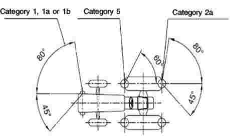
Arrangement D

The value 10° given for the inward angle of visibility of the front indicator may be reduced to 3° for vehicles with an overall width not exceeding 1 400 mm.
Appendix 3
Dimensions, minimum size of the reflecting surface, colour and photometric minimum requirements and identification and marking of signalling panels and signalling foils for vehicles of category S with width exceeding 2,55 m
1. Dimensions, number and minimum reflecting surface
|
1.1. |
Signalling panels and signalling foils shall have the following dimensions: Figure 1 Signalling panel or signalling foil
Figure 2 Basic square
Table 1 Dimensions (mm)
Deviations from the specified formats are permitted, if the surface of the unspecified formats contains at least 3 basic squares. The number of signalling panels or foils for each effective direction to the front and the rear are specified in Table 2. |


|
1.2. |
Table 2 Number of signalling panels or foils for each effective direction
Signalling panels or foils of Form A may be combined with lamps, if the surface of the boards covered by the lamps does not exceed 150 cm2. |
2. Colouring and photometric minimum requirements
White according to point 2.29.1 of UNECE Regulation No 48, as referred to in Annex I.
Red according to point 2.29.4 of UNECE Regulation No 48.
The photometric requirements set out in Annex 7 to UNECE Regulation No. 69, as referenced in Annex I, or in Annex 7 to UNECE Regulation No 104, as referenced in Annex I, apply.
Panels or foils of Form B shall comply with Annex 7 to UNECE Regulation No 104, Class C.
3. Identification
Signalling panels which comply with the requirements set out in this Regulation are marked with the number of this Regulation and the name of the manufacturer.
ANNEX XIII
Requirements on vehicle occupant protection, including interior fittings, head restraints, seat belts, vehicle doors
PART 1
1. Definitions
For the purposes of this Annex:
Definitions for the protection of drive components, in accordance with the requirements laid down on the basis of Article 18 (4) of Regulation (EU) 167/2013, are valid for this Annex.
|
1.1. |
‘Interior fittings’ mean the interior parts of the passenger compartment other than the interior rear-view mirrors and include
|
|
1.2. |
‘Level of the instrument panel’ means the line defined by the points of contact of vertical tangents to the instrument panel. |
|
1.3. |
‘Power-operated windows’ means windows which are closed by power supply of the vehicle. |
|
1.4. |
‘Opening’ is the maximum unobstructed aperture between the upper edge or the leading edge, depending on the closing direction, of a power-operated window or partition or roof panel and the vehicle structure which forms the boundary of the window, partition or roof panel, when viewed from the interior of the vehicle or, in the case of partition system, from the rear part of the passenger compartment. |
PART 2
Interior fittings
1. Specifications
1.1. Interior parts of the passenger compartment excluding the side doors
1.1.1. Environment of driving seat and passenger seats, if fitted
|
1.1.1.1. |
The safety distance zone A above the SIP of the driving seat and located in front of it, as determined in Figure 1, shall not contain any dangerous roughness or sharp edges, likely to increase the risk of serious injury to the occupants. If parts contained in the safety distance zone A above the SIP, located in front of it, comply with the requirements in points 1.1.2 to 1.1.6, they shall be deemed to also comply with this requirement. Figure 1
|
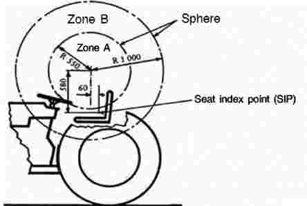
|
1.1.1.2. |
The safety distance zone A, whose centre is 670 mm above the centre of the front edge of the front passenger seat, if fitted, and located in front of it, as determined in Figure 2, shall not contain any dangerous roughness or sharp edges, likely to increase the risk of serious injury to the occupants. If parts contained in the safety distance zone A above the SIP, located in front of it, comply with the requirements in points 1.1.2 to 1.1.6, they shall be deemed to also comply with this requirement. Figure 2
|

|
1.1.1.3. |
In the case of vehicles equipped with steering wheel and bench seats or bucket seats in more than one row, the environment of the rear passenger seats, if fitted, shall comply with the requirements of Annex XVII of the Regulation (EU) No 3/2014. (1) |
1.1.2. Parts that are likely to be contacted by the driver or passengers shall have no sharp edges or rough surfaces hazardous to the occupants.
1.1.3. For tractors with maximum design speed exceeding 40 km/h, the requirements of points 1.1.3.1-1.1.3.4 shall apply in addition to the requirements of points 1.1.1-1.1.2., 1.1.5-1.1.6 and Parts 3-5:
|
1.1.3.1. |
Any metal support fittings shall have no protruding edges. |
|
1.1.3.2. |
The parts that can be contacted by a hemisphere with a diameter of 165 mm, as described in point 3.2.1, when approaching along the radius of zone A in Figure 1, shall be rounded to a radius of curvature of not less than 2,5 mm. |
|
1.1.3.3. |
Window winders, if fitted, may project 35 mm from the surface of the panel. |
|
1.1.3.4. |
Requirements of points 1.1.3.1, 1.1.3.2 and 1.1.3.3 do not apply to components located beyond the steering wheel, as referenced from the apex of a cone, this apex being the centre of zone A in Figure 1, and the rim of the steering wheel being the generatrix of that cone. |
1.1.4. For tractors with maximum design speed exceeding 60 km/h, the requirements of points 1.1.4.1-1.1.4.6 shall apply in addition to the requirements of points 1.1.1-1.1.3.4, 1.1.5-1.1.6 and Parts 3-5:
|
1.1.4.1. |
The lower edge of the instrument panel shall be rounded to a radius of curvature of not less than 19 mm. |
|
1.1.4.2. |
Switches, pull-knobs, etc., made of rigid material, which, measured in accordance with the method described in 3 from 3,2 mm to 9,5 mm from the panel, shall have a cross-sectional area of not less than 2 cm2, measured 2,5 mm from the point projecting furthest, and shall have rounded edges with a radius of curvature of not less than 2,5 mm. |
|
1.1.4.3. |
If these components project by more than 9,5 mm from the surface of the instrument panel, they shall be designed and constructed with a cross-section of not less than 6,50 cm2 in area situated not more than 6,5 mm from the point of maximum projection. |
|
1.1.4.4. |
Components mounted on the roof, if fitted, but which are not part of the roof structure, such as grab handles, lights and ventilation openings, etc., shall have a radius of curvature of not less than 3,2 mm and, in addition, the width of the projecting parts shall not be less than the amount of their downward projection. |
|
1.1.4.5. |
In the case of a projection consisting of a component made of non-rigid material of less than 60 Shore A hardness mounted on a rigid support, the requirements of points 1.1.4.2-1.1.4.4 shall apply only to the rigid support. |
|
1.1.4.6. |
The requirements set out in this section shall apply to fittings not mentioned in points 1.1.2-1.1.6 which, in accordance with the requirements set out in points 1.1.1 to 1.1.6 and according to their location in the vehicle, are capable of being contacted by the occupants. If such parts are made of a material softer than 60 Shore A hardness and mounted on one or more rigid supports, the requirements in question shall apply only to those rigid supports. |
1.1.5. Shelves and other similar items, if fitted, shall be so designed and constructed that their supports in no case have protruding edges.
1.1.6. Other items of equipment in the vehicle not covered by the preceding points such as seat slide rails, equipment for regulating the horizontal or vertical part of the seat, devices for retracting safety belts, etc. shall not be subject to any of these provisions if they are situated below a horizontal plane passing through the seat index point of each seat, even though the occupant is likely to come into contact with such items.
2. Test procedure for the EU type-approval
|
2.1.1. |
The application for EU component type-approval shall be accompanied by the following samples that shall be submitted to the technical service responsible for conducting the component type-approval tests: |
|
2.1.2. |
at the manufacturer's discretion, either a vehicle representative of the vehicle type to be approved or the part(s) of the vehicle regarded as essential for the checks and tests prescribed by this Regulation; and |
|
2.1.3. |
at the request of the aforesaid technical service, certain components and certain samples of the materials used. |
3. Method of measuring projections
3.1. To determine the amount by which an item projects in relation to the panel on which it is mounted, a 165 mm sphere shall be moved along and be kept in contact with the component under consideration, starting from the initial position of contact with the component under consideration. The projection's value is the largest of all possible variations «y», the variation measured from the centre of the sphere perpendicular to the panel.
If the panels and components, etc., are covered with materials softer than 50 Shore A hardness, the procedure for the measuring of projections described above shall apply only after the removal of such materials.
The projection of switches, pull-knobs, etc., situated in the reference area shall be measured by using the test apparatus and procedure described below:
3.2. Apparatus
|
3.2.1. |
The measuring apparatus for projections shall consist of a hemispherical headform 165 mm in diameter, in which there is a sliding ram of 50 mm diameter. |
|
3.2.2. |
Relative positions of the flat end of the ram and the edge of the headform shall be shown on a graduated scale, on which a mobile index shall register the maximum measurement achieved when the apparatus is moved away from the item tested. A minimum distance of 30 mm shall be measurable; the measuring scale shall be graduated in half-millimetres to make possible an indication of the extent of the projections in question. |
|
3.2.3. |
Gauging procedure:
|
|
3.2.4. |
The apparatus for measuring projections is illustrated in Figure 3. |
3.3. Test procedure
|
3.3.1. |
A cavity shall be formed in the headform by pulling back the ram and the mobile index shall be placed against the ram. |
|
3.3.2. |
The apparatus shall be applied to the projection to be measured so that the headform contacts the maximum surrounding surface area, with a force not exceeding 2 daN. |
|
3.3.3. |
The ram shall be pushed forward until it makes contact with the projection to be measured and the amount of the projection shall be observed on the scale. |
|
3.3.4. |
The headform shall be adjusted to obtain maximum projection. The amount of the projection shall be recorded. |
|
3.3.5. |
If two or more controls are situated sufficiently close for the ram or the headform to contact them simultaneously, they shall be treated as follows:
|
Figure 3
Apparatus for measuring projections

4. Apparatus and procedure for application of point 1.1.1.
Those parts (switches, pull-knobs etc.) which can be contacted by using the apparatus and procedure described below shall be considered as being likely to be contacted by the knees of an occupant:
4.1. Apparatus
Diagram of apparatus

4.2. Procedure
The apparatus may be placed in any position below the instrument panel so that:
|
— |
the plane XX' remains parallel to the median longitudinal plane of the vehicle, |
|
— |
the axis X can be rotated above and below the horizontal through angles up to 30°. In carrying out the test referred to in this point, all materials of less than 60 Shore A hardness shall be removed. |
PART 3
Head restraints, if fitted
Head restraints, if fitted shall comply with the provisions of UNECE Regulation No 25, as referenced in Annex I.
PART 4
Seat belts
The requirements laid down on the basis of Article 18(2)(j) and (4) of Regulation (EU) No 167/2013 shall apply.
PART 5
Vehicle doors, if fitted
Vehicle doors, with powered windows and powered roof hatches, if fitted, shall comply with paragraphs 5.8.1 to 5.8.5 of UNECE Regulation No 21, as referenced in Annex I.
(1) Commission Delegated Regulation (EU) No 3/2014 of 24 October 2013 supplementing Regulation (EU) No 168/2013 of the European Parliament and of the Council with regard to vehicle functional safety requirements for the approval of two- or three-wheel vehicles and quadricycles (OJ L 7, 10.01.2014, p. 1).
ANNEX XIV
Requirements on vehicle exterior and accessories
1. Definitions
For the purposes of this Annex:
|
1.1. |
‘External surface’ means the outside of the vehicle including wheels, tracks, doors, bumpers, bonnet, access means, tanks. |
|
1.2. |
‘Radius of curvature’ means the radius of the arc of a circle which comes closest to the rounded form of the component under consideration. |
|
1.3. |
‘Extreme outer edge’ of the vehicle means, in relation to the sides of the vehicle, the plane parallel to the median longitudinal plane of the vehicle coinciding with its outer lateral edge, and, in relation to the front and rear ends, the perpendicular transverse plane of the vehicle coinciding with its outer front and rear edges, account not being taken of the projection:
|
2. Scope
|
2.1 |
This Annex shall apply to those parts, of the external surface which, with the vehicle in the laden condition, equipped with tyres of the highest diameter or set of tracks of the highest vertical dimension, for which it is approved, with all doors, windows and access lids etc., in the closed position, are either:
|
|
2.2. |
The purpose of these provisions is to reduce the risk or seriousness of bodily injury to a person hit by the exterior of the vehicle or brushing against it in the event of a collision. This is valid both when the vehicle is stationary and in motion. |
|
2.3. |
This Annex does not apply to exterior rear-view mirrors. |
|
2.4. |
This Annex do not apply to the metallic tracks of vehicles of category C. |
3. Requirements
|
3.1. |
The external surface of the vehicle shall not exhibit, directed outwards, any pointed or sharp parts, rough surfaces, or any projections of such shape, dimensions, direction or hardness as to be likely to increase the risk or seriousness of bodily injury to a person hit by the external surface or brushing against it in the event of a collision. |
|
3.2. |
The external surfaces on each side of the vehicle shall not exhibit, directed outwards, any parts likely to catch on pedestrians, cyclists or motor cyclists. |
|
3.3. |
No protruding part of the external surface shall have a radius of curvature less than 2,5 mm. This requirement shall not apply to parts of the external surface which protrude less than 5 mm, but the outward facing angles of such parts shall be blunted, save where such parts protrude less than 1.5 mm. |
|
3.4. |
Protruding parts of the external surface, made of a material of hardness not exceeding 60 Shore A, may have a radius of curvature less than 2,5 mm. The hardness measurement by the Shore A procedure can be replaced by a hardness value declaration from the manufacturer of the component. |
|
3.5. |
Vehicles equipped with hydro-pneumatic, hydraulic or pneumatic suspension or a device for automatic levelling according to load shall be tested with the vehicle in the most adverse normal running condition specified by the manufacturer. |
|
3.6. |
Exposed ground or crop engaging tools and material distribution devices on vehicles of category R & S that have sharp edges or teeth when folded in road transport mode and that are already covered by Directive 2006/42/EC are exempted from complying with points 3.1 to 3.5. For exposed areas of any other part of vehicles of category R & S, points 3.1 to 3.5 shall apply. |
ANNEX XV
Requirements on the electromagnetic compatibility
PART 1
This Annex applies to the electromagnetic compatibility of vehicles covered by Article 2 of Regulation (EU) No 167/2013. It also applies to electrical or electronic separate technical units intended to be fitted to the vehicles.
Definitions
For the purposes of this Annex, the following definitions apply:
|
1. |
‘Electromagnetic compatibility’ means the ability of a vehicle or component(s) or separate technical unit(s) to function satisfactorily in its electromagnetic environment without introducing intolerable electromagnetic disturbances to anything in that environment; |
|
2. |
‘Electromagnetic disturbance’ means any electromagnetic phenomenon which may degrade the performance of a vehicle or component(s) or separate technical unit(s). An electromagnetic disturbance may be electromagnetic noise, an unwanted signal or a change in the propagation medium itself; |
|
3. |
‘Electromagnetic immunity’ means the ability of a vehicle or component(s) or separate technical unit(s) to perform without degradation of performance in the presence of specified electromagnetic disturbances; |
|
4. |
‘Electromagnetic environment’ means the totality of electromagnetic phenomena existing at a given location; |
|
5. |
‘Reference limit’ means the nominal level to which type-approval and conformity of production limit values are referenced; |
|
6. |
‘Reference antenna’ for the frequency range 20 to 80 MHz: means a shortened balanced dipole being a half wave resonant dipole at 80 MHz, and for the frequency range above 80 MHz: means a balanced half wave resonant dipole tuned to the measurement frequency; |
|
7. |
‘Broadband electromagnetic emission’ means an emission which has a bandwidth greater than that of a particular measuring apparatus or receiver; |
|
8. |
‘Narrowband electromagnetic emission’ means an emission which has a bandwidth less than that of a particular measuring apparatus or receiver; |
|
9. |
‘Electrical/electronic system’ means (an) electrical and/or electronic device(s) or set(s) of devices together with any associated electrical connections which form part of a vehicle but which are not intended to be type approved separately from the vehicle; |
|
10. |
‘Electrical/electronic sub-assembly’ (ESA) means an electrical and/or electronic device or set(s) of devices intended to be part of a vehicle, together with any associated electrical connections and wiring, which performs one or more specialised functions; |
|
11. |
‘Type of ESA’ in relation to electromagnetic compatibility means ESAs which do not differ as to the function performed or the general arrangement of the electrical and/or electronic components, if applicable. |
PART 2
Requirements to be met by vehicles and electrical / electronic sub-assemblies fitted to a vehicle
1. Application for EU type-approval
1.1 Approval of a vehicle type
|
1.1.1. |
The application for approval of a vehicle type, with regard to its electromagnetic compatibility pursuant to Articles 22, 24 and 26 of Regulation (EU) No 167/2013 shall be submitted by the vehicle manufacturer. |
|
1.1.2. |
The vehicle manufacturer shall submit the information document, the model of which is set out in Article 68(a) of Regulation (EU) No 167/2013. |
|
1.1.3. |
The vehicle manufacturer shall draw up a schedule describing all projected combinations of relevant vehicle electrical/electronic systems or ESAs, body styles (1), variations in body material (2), general wiring arrangements, engine variations, left-hand/right-hand drive versions and wheelbase versions. Relevant vehicle electrical/electronic systems or ESAs are those which may emit significant broadband or narrowband radiation and/or those which are involved in the driver’s direct control (see point 3.4.2.3) of the vehicle. |
|
1.1.4. |
A representative vehicle shall be selected from this schedule for the purpose of being tested, in mutual agreement between the manufacturer and the competent authority. This vehicle shall represent the vehicle type specified in the information document set out in Article 68(a) of Regulation (EU) No 167/2013. The choice of vehicle shall be based on the electrical/electronic systems offered by the manufacturer. One more vehicle may be selected from this schedule for the purpose of being tested if it is considered by mutual agreement between the manufacturer and the competent authority that different electrical/electronic systems are included which are likely to have a significant effect on the vehicle's electromagnetic compatibility compared with the first representative vehicle. |
|
1.1.5. |
The choice of the vehicle(s) in conformity with point 1.1.4 is limited to vehicle/electrical/electronic system combinations intended for actual production. |
|
1.1.6. |
The manufacturer may supplement the application with a report from tests which have been carried out. Any such data provided may be used by the approval authority for the purpose of drawing up the EU type-approval certificate. |
|
1.1.7. |
A vehicle representative of the type to be approved, according to point 1.1.4 shall be provided to the technical service that carries out the test itself. |
1.2. Approval of a type of ESA
|
1.2.1. |
The application for approval of a type of ESA with regard to its electromagnetic compatibility pursuant to Articles 22, 24 and 26 of Regulation (EU) No 167/2013 shall be submitted by the vehicle manufacturer or by the manufacturer of the ESA. An ESA may be approved at the request of a manufacturer as either a ‘component’ or a ‘separate technical unit (STU)’. |
|
1.2.2. |
The vehicle manufacturer shall submit the information document, the model of which is set out in Article 68(a) of Regulation (EU) No 167/2013. |
|
1.2.3. |
The manufacturer may supplement the application with a report from tests which have been carried out. Any such data provided may be used by the approval authority for the purpose of drawing up the EU type-approval certificate. |
|
1.2.4. |
A sample of the ESA representative of the type to be approved shall be provided to the technical service that carries out the test itself, if necessary, after discussion with the manufacturer on, for example, possible variations in the layout, the number of components and the number of sensors. If the technical service deems it necessary, it may select a further sample. |
|
1.2.5. |
The sample(s) shall be clearly and indelibly marked with the manufacturer's trade name or mark and the type designation. |
|
1.2.6. |
Where applicable, any restrictions on use shall be identified. Any such restrictions shall be included in the information document set out in Article 68(a) of Regulation (EU) No 167/2013 and/or in the EU type-approval certificate set out in Article 68(c) of Regulation (EU) No 167/2013. |
2. Marking
|
2.1. |
Every ESA conforming to a type approved pursuant to this Regulation shall bear an EU type-approval mark in accordance with Article 34 of Regulation (EU) No 167/2013 and Annex XX to this Regulation. |
|
2.2. |
No marking is required for electrical/electronic systems included in vehicle types approved by this Regulation. |
|
2.3. |
Markings on ESAs in compliance with points 2.1 and 2.2 need not be visible when the ESA is installed in a vehicle. |
3. Specifications
3.1. General specification
|
3.1.1. |
A vehicle (and its electrical/electronic system(s) or ESAs) shall be so designed, constructed and fitted as to enable the vehicle, in normal conditions of use, to comply with this Regulation. |
3.2. Specifications concerning broadband electromagnetic radiation from vehicles fitted with spark ignition.
3.2.1. Method of measurement
The electromagnetic radiation generated by the vehicle representative of its type shall be measured using the method described in Part 3 at either of the defined antenna distances. The choice shall be made by the vehicle manufacturer.
3.2.2. Vehicle broadband reference limits
|
3.2.2.1. |
If measurements are made using the method described in Part 3 using a vehicle-to-antenna spacing of 10,0 ± 0,2 m, the radiation reference limits shall be 34 dB microvolts/m (50 microvolts/m) in the 30 to 75 MHz frequency band and 34 to 45 dB microvolts/m (50 to 180 microvolts/m) in the 75 to 400 MHz frequency band, this limit increasing logarithmically (linearly) with frequencies above 75 MHz as shown in point 5. In the 400 to 1 000 MHz frequency band the limit remains constant at 45 dB microvolts/m (180 microvolts/m). |
|
3.2.2.2. |
If measurements are made using the method described in Part 3 using a vehicle-to-antenna spacing of 3,0 ± 0,05 m, the radiation reference limits shall be 44 dB microvolts/m (160 microvolts/m) in the 30 to 75 MHz frequency band and 44 to 55 dB microvolts/m (160 to 562 microvolts/m) in the 75 to 400 MHz frequency band, this limit increasing logarithmically (linearly) with frequencies above 75 MHz as shown in point 6. In the 400 to 1 000 MHz frequency band the limit remains constant at 55 dB microvolts/m (562 microvolts/m). |
|
3.2.2.3. |
On the vehicle representative of its type, the measured values, expressed in dB microvolts/m (microvolts/m), shall be at least 2,0 dB (20 %) below the reference limits. |
3.3. Specifications concerning narrowband electromagnetic radiation from vehicles
3.3.1. Method of measurement
The electromagnetic radiation generated by the vehicle representative of its type shall be measured using the method described in Part 4 at either of the defined antenna distances. The choice shall be made by the vehicle manufacturer.
3.3.2. Vehicle narrowband reference limits
|
3.3.2.1. |
If measurements are made using the method described in Part 4 using a vehicle-to-antenna spacing of 10,0 ± 0,2 m, the radiation-reference limits shall be 24 dB microvolts/m (16 microvolts/m) in the 30 to 75 MHz frequency band and 24 to 35 dB microvolts/m (16 to 56 microvolts/m) in the 75 to 400 MHz frequency band, this limit increasing logarithmically (linearly) with frequencies above 75 MHz as shown in point 7. In the 400 to 1 000 MHz frequency band the limit remains constant at 35 dB microvolts/m (56 microvolts/m). |
|
3.3.2.2. |
If measurements are made using the method described in Part 4 using a vehicle-to-antenna spacing of 3,0 ± 0,05 m, the radiation reference limit shall be 34 dB microvolts/m (50 microvolts/m) in the 30 to 75 MHz frequency band and 34 to 45 dB microvolts/m (50 to 180 microvolts/m) in the 75 to 400 MHz frequency band, this limit increasing logarithmically (linearly) with frequencies above 75 MHz as shown in point 8. In the 400 to 1 000 MHz frequency band the limit remains constant at 45 dB microvolts/m (180 microvolts/m). |
|
3.3.2.3. |
On the vehicle representative of its type, the measured values, expressed in dB microvolts/m (microvolts/m), shall be at least 2,0 dB (20 %) below the reference limit. |
|
3.3.2.4. |
Notwithstanding the limits defined in points 5.3.2.1, 5.3.2.2 and 5.3.2.3, if, during the initial step described in point 1.3 of Part 4, the signal strength measured at the vehicle broadcast radio antenna is less than 20 dB microvolts/m (10 microvolts/m) over the frequency range 88 to 108 MHz, then the vehicle shall be deemed to comply with the limits for narrowband emissions and no further testing shall be required. |
3.4. Specifications concerning immunity of vehicles to electromagnetic radiation
3.4.1. Method of testing
The immunity to electromagnetic radiation of the vehicle representative of its type shall be tested by the method described in Part 5.
3.4.2. Vehicle immunity reference limits
|
3.4.2.1. |
If tests are made using the method described in Part 5, the field strength reference level shall be 24 volts/m rms in over 90 % of the 20 to 1 000 MHz frequency band and 20 volts/m rms over the whole 20 to 1 000 MHz frequency band. |
|
3.4.2.2. |
The vehicle representative of its type shall be considered as complying with immunity requirements if, during the tests performed in accordance with Part 5, and subjected to a field strength, expressed in volts/m, of 25 % above the reference level, there shall be no abnormal change in the speed of the driven wheels of the vehicle, no degradation of performance which would cause confusion to other road users, and no degradation in the driver's direct control of the vehicle which could be observed by the driver or other road user. |
|
3.4.2.3. |
The driver’s direct control of the vehicle is exercised by means of steering, braking, or engine speed control. |
3.5. Specification concerning broadband electromagnetic interference generated by ESAs
3.5.1. Method of measurement
The electromagnetic radiation generated by the ESA representative of its type shall be measured by the method described in Part 6.
3.5.2. ESA broadband reference limits
|
3.5.2.1. |
If measurements are made using the method described in Part 6, the radiation reference limits shall be 64 to 54 dB microvolts/m (1 600 to 500 microvolts/m) in the 30 to 75 MHz frequency band, this limit decreasing logarithmically (linearly) with frequencies above 30 MHz, and 54 to 65 dB microvolts/m (500 to 1 800 microvolts/m) in the 75 to 400 MHz band, this limit increasing logarithmically (linearly) with frequencies above 75 MHz as shown in point 9 of this Part. In the 400 to 1 000 MHz frequency band the limit remains constant at 65 dB microvolts/m (1 800 microvolts/m). |
|
3.5.2.2. |
On the ESA representative of its type, the measured values, expressed in dB microvolts/m, (microvolts/m) shall be at least 2,0 dB (20 %) below the reference limits. |
3.6. Specifications concerning narrowband electromagnetic interference generated by ESAs
3.6.1. Method of measurement
The electromagnetic radiation generated by the ESA representative of its type shall be measured by the method described in Part 7.
3.6.2. ESA narrowband reference limits
|
3.6.2.1. |
If measures are made using the method described in Part 7, the radiation reference limits shall be 54 to 44 dB microvolts/m (500 to 160 microvolts/m) in the 30 to 75 MHz frequency band, this limit decreasing logarithmically (linearly) with frequencies above 30 MHz, and 44 to 55 dB microvolts/m (160 to 560 microvolts/m) in the 75 to 400 MHz band, this limit increasing logarithmically (linearly) with frequencies above 75 MHz as shown in point 10 of this Part. In the 400 to 1 000 MHz frequency band the limit remains constant at 55 dB microvolts/m (560 microvolts/m). |
|
3.6.2.2. |
On the ESA representative of its type, the measured value, expressed in dB microvolts/m (microvolts/m) shall be at least 2,0 dB (20 %) below the reference limits. |
3.7. Specifications concerning immunity of ESAs to electromagnetic radiation
3.7.1. Method(s) of testing
The immunity to electromagnetic radiation of the ESA representative of its type shall be tested by the method(s) chosen from those described in Part 8.
3.7.2. ESA immunity reference limits
|
3.7.2.1. |
If tests are made using the methods described in Part 8, the immunity test reference levels shall be 48 volts/m for the 150 mm stripline testing method, 12 volts/m for the 800 mm stripline testing method, 60 volts/m for the transverse electromagnetic mode (TEM) cell testing method, 48 mA for the bulk current injection (BCI) testing method and 24 volts/m for the free field testing method. |
|
3.7.2.2. |
On the ESA representative of its type at a field strength or current expressed in appropriate linear units 25 % above the reference limit, the ESA shall not exhibit any malfunction which would cause any degradation of performance which could cause confusion to other road users or any degradation in the driver's direct control of a vehicle fitted with the system which could be observed by the driver or other road user. |
4. Exceptions
4.1. Where a vehicle or electrical/electronic system or ESA does not include an electronic oscillator with an operating frequency greater than 9 kHz, it shall be deemed to comply with point 3.3.2 or 3.6.2 and with Parts 4 and 7.
4.2. Vehicles which do not have electrical/electronic systems or ESAs involved in the direct control of the vehicle need not be tested for immunity and shall be deemed to comply with point 3.4 and with Part 5.
4.3. ESAs whose functions are not involved in the direct control of the vehicle need not be tested for immunity and shall be deemed to comply with point 3.7 and with Part 8.
4.4. Electrostatic discharge
For vehicles fitted with tyres, the vehicle body/chassis can be considered to be an electrically isolated structure. Significant electrostatic forces in relation to the vehicle's external environment only occur at the moment of occupant entry into or exit from the vehicle. As the vehicle is stationary at these moments, no type-approval test for electrostatic discharge is deemed necessary.
4.5. Conducted transients
Since during normal driving no external electrical connections are made to vehicles, no conducted transients are generated in relation to the external environment. The responsibility of ensuring that equipment can tolerate the conducted transients within a vehicle, for example due to load switching and interaction between systems, shall lie with the manufacturer. No type-approval test for conducted transients shall be deemed necessary.
5. Vehicle broadband reference limits with antenna-vehicle separation of 10 m
Frequency — megahertz — logarithmic
(See point 3.2.2.1 of Part 2)

6. Vehicle broadband reference limits with antenna-vehicle separation of 3 m
Frequency — megahertz — logarithmic
(See point 3.2.2.2 of Part 2)

7. Vehicle narrowband reference limits with antenna-vehicle separation of 10 m
Frequency — megahertz — logarithmic
(See point 3.3.2.1 of Part 2)

8. Vehicle narrowband reference limits with antenna-vehicle separation of 3 m
Frequency — megahertz — logarithmic
(See point 3.3.2.2 of Part 2)

9. Broadband reference limits of electrical / electronic sub-assembly
Frequency — megahertz — logarithmic
(See point 3.5.2.1 of Part 2)

10. Narrowband reference limits of electrical / electronic sub-assembly
Frequency — megahertz — logarithmic
(See point 3.6.2.1 of Part 2)

PART 3
Requirements to be met by vehicles: method of measurement of radiated broadband electromagnetic emissions from vehicles
1. General
1.1. The test method described in this Part shall only be applied to vehicles.
1.2. Measuring apparatus
The measuring equipment shall comply with the requirements of publication No 16-1 series of the International Special Committee on Radio Interference (CISPR).
A quasi-peak detector shall be used for the measurement of broadband electromagnetic emissions in this Part, or if a peak detector is used an appropriate correction factor shall be used depending on the spark pulse rate.
1.3. Test method
This test is intended to measure the broadband electromagnetic emissions generated by spark-ignition systems and by electric motors (electric traction motors, engines for heating or de-icing systems, fuel pumps, water pumps, etc.) permanently fitted to the vehicle.
Two alternative reference antenna distances are permissible: 10 or 3 m from the vehicle. In either case point 3 shall apply.
2. Expression of results
The results of measurements shall be expressed in dB microvolts/m (microvolt/m) for 120 kHz band width. If the actual band width B (expressed in kHz) of the measuring apparatus differs from 120 kHz, the readings taken in microvolts/m shall be converted to 120 kHz band width through multiplication by a factor 120/B.
3. Measuring location
3.1. The test site shall be a level, clear area free from electromagnetic reflecting surfaces within a circle of minimum radius 30 m measured from a point midway between the vehicle and the antenna (see Figure 1 in point 7).
3.2. The measuring set, test hut, or vehicle in which the measurement set is located may be within the test site, but only in the permitted region shown in Figure 1 in point 7.
Other measuring antennae are allowed within the test area, at a minimum distance of 10 m both from receiving antenna and the vehicle under test, provided that it can be shown that the test results will not be affected.
3.3. Enclosed test facilities may be used if correlation can be shown between the enclosed test facility and an outdoor site. Enclosed test facilities do not need to meet the dimensional requirements of Figure 1 in point 7 other than the distance from the antenna to the vehicle and the height of the antenna. Neither do they need to have ambient emissions checked before or after the test as indicated in point 3.4.
3.4. Ambient
To ensure that there is no extraneous noise or signal of a magnitude sufficient to affect materially the measurement, measurements shall be taken before and after the main test. If the vehicle is present when ambient measurements are taken, the technical service shall ensure that any emissions from the vehicle do not affect significantly the ambient measurements, for example by removing the vehicle from the test area, removing the ignition key, or disconnecting the battery. In both of the measurements, the extraneous noise or signal shall be at least 10 dB below the limits of interference given in point 3.2.2.1 or 3.2.2.2 (as appropriate) of Part 2, except for intentional narrowband ambient transmissions.
4. Vehicle state during tests
4.1. Engine
The engine shall be running at its normal operating temperature and the transmission shall be in neutral. If for practical reasons this cannot be achieved, alternative arrangements mutually agreed between the manufacturer and the test authorities may be made.
Care shall be taken to ensure that the speed setting mechanism does not influence electromagnetic radiations. During each measurement, the engine shall be operated as follows:
|
Engine type |
Method of measurements |
|
|
Quasi peak |
Peak |
|
|
Spark ignition |
Engine speed |
Engine speed |
|
One cylinder |
2 500 rpm ± 10 % |
2 500 rpm ± 10 % |
|
More than one cylinder |
1 500 rpm ± 10 % |
1 500 rpm ± 10 % |
4.2. Testing shall not be conducted while rain or other precipitation is falling on the vehicle or within 10 minutes after such precipitation has stopped.
5. Antenna type, position and orientation
5.1. Antenna type
Any antenna may be used provided it can be normalised to the reference antenna. The method described in CISPR publication No 12, Edition 6, Annex C may be used to calibrate the antenna.
5.2. Height and distance of measurement
5.2.1. Height
5.2.1.1. 10 m test
The phase centre of the antenna shall be 3,00 ± 0,05 m above the plane on which the vehicle rests.
5.2.1.2. 3 m test
The phase centre of the antenna shall be 1,80 ± 0,05 m above the plane on which the vehicle rests.
5.2.1.3. No part of any antenna’s receiving elements shall be closer than 0,25 m to the plane on which the vehicle rests.
5.2.2. Distance of measurement
5.2.2.1. 10 m test
The horizontal distance from the tip or other appropriate point of the antenna defined during the normalisation procedure described in point 5.1 to the outer body surface of the vehicle shall be 10,0 ± 0,2 m.
5.2.2.2. 3 m test
The horizontal distance from the tip or other appropriate point of the antenna defined during the normalisation procedure described in point 5.1 to the outer body surface of the vehicle shall be 3,00 ± 0,05 m.
5.2.2.3. If the test is carried out in a facility enclosed for radio frequency electromagnetic screening purposes, the antenna's receiving elements shall be no closer than 1,0 m to any radio absorbent material and no closer than 1,5 m to the wall of the enclosed facility. There shall be no absorbent material between the receiving antenna and vehicle under test.
5.3. Antenna location relative to vehicle
The antenna shall be located successively on the left and right-hand sides of the vehicle, with the antenna parallel to the plane of longitudinal symmetry of the vehicle, in line with the engine mid-point (see Figure 1 in point 7) and in line with the vehicle mid-point defined as the point on the principal axis of the vehicle midway between the centres of the front and rear axles of the vehicle.
5.4. Antenna position
At each of the measuring points, readings shall be taken both with the antenna in a horizontal and in a vertical polarisation (see Figure 2 in point 7).
5.5. Readings
The maximum of the four readings taken in accordance with points 5.3 and 5.4 at each spot frequency shall be taken as the characteristic reading at the frequency at which the measurements were made.
6. Frequencies
6.1. Measurements
Measurements shall be made throughout the 30 to 1 000 MHz frequency range. To confirm that the vehicle meets the requirements of this Part, the Testing Authority shall test at up to 13 frequencies in the range, for example 45, 65, 90, 120, 150, 190, 230, 280, 380, 450, 600, 750, 900 MHz. In the event that the limit is exceeded during the test, investigations shall be made to ensure that this is due to the vehicle and not to background radiation.
|
6.1.1. |
The limits apply throughout the frequency range 30 to 1 000 MHz. |
|
6.1.2. |
Measurements can be performed with either quasi-peak or peak detectors. The limits given in points 3.2 and 3.5 of Part 2 are for quasi-peak. If peak is used, add 38 dB for 1 MHz band width or subtract 22 dB for 1 kHz band width. |
6.2. Tolerances
|
Spot frequency (MHz) |
Tolerance (MHz) |
|
45, 65, 90, 120, 150, 190 and 230 |
± 5 |
|
280, 380, 450, 600, 750 and 900 |
± 20 |
The tolerances apply to frequencies quoted and are intended to avoid interference from transmissions operating on or near the nominal spot frequencies during the time of measurement.
7. Figures
Figure 1
Tractor test area
(Level area free from reflecting electromagnetic surfaces)

Position of antenna relative to tractor
Elevation
Dipole antenna in position to measure vertical component of radiation

Figure 2
Plan
Dipole antenna in position to measure horizontal component of radiation

PART 4
Method of measurement of radiated narrowband electromagnetic emissions from vehicles
1. General
1.1. The test method described in this Part shall only be applied to vehicles.
1.2. Measuring apparatus
The measuring equipment shall comply with the requirements of publication No 16-1 series of the International Special Committee on Radio Interference (CISPR).
An average detector or a peak detector shall be used for the measurement of radiated narrowband electromagnetic emissions in this Annex.
1.3. Test method
|
1.3.1. |
This test is intended to measure narrowband electromagnetic emissions such as might emanate from a microprocessor-based system or other narrowband source. |
|
1.3.2. |
As an initial step the levels of emissions in the FM frequency band (88 to 108 MHz) shall be measured at the vehicle broadcast radio antenna with equipment as specified in point 1.2. If the level specified in point 3.3.2.4 of Part 2 is not exceeded, the vehicle shall be deemed to comply with the requirements set out in this Part in respect of that frequency band and the full test shall not be carried out. |
|
1.3.3. |
In the full test procedure two alternative antenna distances are permissible: 10 or 3 m from the vehicle. In either case, the requirements set out in point 3 shall be complied with. |
2. Expression of results
The results of measurements shall be expressed in dB microvolts/m (microvolts/m).
3. Measuring location
3.1. The test site shall be a level, clear area free from electromagnetic reflecting surfaces within a circle of minimum radius 30 m measured from a point midway between the vehicle and the antenna (see Figure 1 in Part 3).
3.2. The measuring set, test hut, or vehicle in which the measurement set is located may be within the test site, but only in the permitted region shown in Figure 1 in Part 3.
Other measuring antennae are allowed within the test area, at a minimum distance of 10 m both from receiving antenna and the vehicle under test, provided that it can be shown that the test results will not be affected.
3.3. Enclosed test facilities may be used if correlation can be shown between the enclosed test facility and an outdoor site. Enclosed test facilities do not need to meet the dimensional requirements of Figure 1 in point 7 of Part 3 other than the distance from the antenna to the vehicle and the height of the antenna. Neither do they need to have ambient emissions checked before or after the test as indicated in point 3.4 of this Part.
3.4. Ambient
To ensure that there is no extraneous noise or signal of a magnitude sufficient to affect materially the measurement, ambient measurements shall be taken before and after the main test. The technical service shall ensure that any emissions from the vehicle do not affect significantly the ambient measurements, for example by removing the vehicle from the test area, removing the ignition key, or disconnecting the battery(ies). In both of the measurements, the extraneous noise or signal shall be at least 10 dB below the limits of interference given in point 3.3.2.1 or 3.3.2.2 (as appropriate) of Part 2, except for intentional narrowband ambient transmissions.
4. Vehicle state during tests
|
4.1. |
The vehicle’s electronic systems shall all be in normal operating mode with the vehicle stationary. |
|
4.2. |
The ignition shall be switched on. The engine shall not be operating. |
|
4.3. |
Measurements shall not be made while rain or other precipitation is falling on the vehicle or within 10 minutes after such precipitation has stopped. |
5. Antenna type, position and orientation
5.1. Antenna type
Any antenna may be used provided that it can be normalised to the reference antenna. The method described in the CISPR publication No 12, Edition 6, Annex C, may be used to calibrate the antenna.
5.2. Height and distance of measurement
5.2.1. Height
5.2.1.1. 10 m test
The phase centre of the antenna shall be 3,00 ± 0,05 m above the plane on which the vehicle rests.
5.2.1.2. 3 m test
The phase centre of the antenna shall be 1,80 ± 0,05 m above the plane on which the vehicle rests.
5.2.1.3. No part of any antenna's receiving elements shall be closer than 0,25 m to the plane on which the vehicle rests.
5.2.2. Distance of measurement
5.2.2.1. 10 m test
The horizontal distance from the tip or other appropriate point of the antenna defined during the normalisation procedure described in point 5.1 to the outer body surface of the vehicle shall be 10,0 ± 0,2 m.
5.2.2.2. 3 m test
The horizontal distance from the tip or other appropriate point of the antenna defined during the normalisation procedure described in point 5.1 to the outer body surface of the vehicle shall be 3,00 ± 0,05 m.
5.2.2.3. If the test is carried out in a facility enclosed for radio frequency electromagnetic screening purposes, the antenna's receiving elements shall be no closer than 1,0 m to any radio absorbent material and no closer than 1,5 m to the wall of the enclosed facility. There shall be no absorbent material between the receiving antenna and vehicle under test.
5.3. Antenna location relative to vehicle
The antenna shall be located successively on the left and right-hand sides of the vehicle with the antenna parallel to the plane of longitudinal symmetry of the vehicle and in line with the engine mid-point (see Figure 2 in point 7 of Part 3).
5.4. Antenna position
At each of the measuring points, readings shall be taken both with the antenna in a horizontal and in a vertical polarisation (see Figure 2 in point 7 of Part 3).
5.5. Readings
The maximum of the four readings taken in accordance with points 5.3 and 5.4 at each spot frequency shall be taken as the characteristic reading at the frequency at which the measurements are made.
6. Frequencies
6.1. Measurements
Measurements shall be made throughout the 30 to 1 000 MHz frequency range. This range shall be divided into 13 bands. In each band one spot frequency may be tested to demonstrate that the required limits are satisfied. To confirm that the vehicle meets the requirements of this Part, the testing authority shall test at one such point in each of the following 13 frequency bands:
30 to 50, 50 to 75, 75 to 100, 100 to 130, 130 to 165, 165 to 200, 200 to 250, 250 to 320, 320 to 400, 400 to 520, 520 to 660, 660 to 820, 820 to 1 000 MHz.
In the event that the limit is exceeded during the test, investigations shall be made to ensure that this is due to the vehicle and not to background radiation.
PART 5
Method of testing for immunity of vehicles to electromagnetic radiation
1. General
1.1. The test method described in this Part shall only be applied to vehicles.
1.2. Test method
This test is intended to demonstrate the immunity to degradation in the direct control of the vehicle. The vehicle shall be subject to electromagnetic fields as described in this Part. For tests with the vehicle exposed to electromagnetic radiation of frequency not exceeding 1 000 MHz, manufacturers may choose whether to apply either this Part or Annex 6 to UNECE Regulation No 10 as referenced in Annex I. For tests with the vehicle exposed to electromagnetic radiation of frequency exceeding 1 000 MHz and not exceeding 2 000 MHz, manufacturers shall apply Annex 6 to UNECE Regulation No 10 as referenced in Annex I. The vehicle shall be monitored during the tests.
2. Expression of results
For the test described in this Part, field strengths shall be expressed in volts/m.
3. Measuring location
The test facility shall be capable of generating the field strengths over the frequency ranges defined in this Part. The test facility shall comply with legal requirements regarding the emission of electromagnetic signals.
Care shall be taken so that the control and monitoring equipment shall not be affected by radiated fields in such a way as to invalidate the tests.
4. Vehicle state during tests
|
4.1. |
The vehicle shall be in an unladen condition except for necessary test equipment. |
|
4.1.1. |
The engine shall turn the driving wheels normally at a constant speed corresponding to three quarters of the maximum speed of the vehicle if there is no technical reason for the manufacturer to prefer another speed. The vehicle’s engine shall be loaded with an appropriate torque. If need be, the transmission shafts may be disengaged (for example, in the case of vehicles with more than two axles), provided they do not drive a component-emitting interference. |
|
4.1.2. |
Headlamps shall be on dipped beam. |
|
4.1.3. |
Left or right-direction indicator shall be operating. |
|
4.1.4. |
All other systems which affect the driver's control of the vehicle shall be (on) as in normal operation of the vehicle. |
|
4.1.5. |
The vehicle shall not be electrically connected to the test area and no connections shall be made to the vehicle from any equipment, except as required by point 4.1.1 or 4.2. Tyre contact with the test area floor shall not be considered to be an electrical connection. |
|
4.2. |
If there are vehicle electrical/electronic systems which form an integral part of the direct control of the vehicle, which will not operate under the conditions described in point 4.1, the manufacturer may provide a report or additional evidence to the testing authority that the vehicle electrical/electronic system meets the requirements of this Regulation. Such evidence shall be retained in the type-approval documentation. |
|
4.3. |
Only non-perturbing equipment shall be used while monitoring the vehicle. The vehicle exterior and the passenger compartment shall be monitored to determine whether the requirements of this Part are met (for example by using (a) video camera(s)). |
|
4.4. |
The vehicle shall normally face a fixed antenna. However, where the electronic control units and the associated wiring harness are predominantly in the rear of the vehicle, the test shall normally be carried out with the vehicle facing away from the antenna. In the case of long vehicles (namely excluding cars and light vans), which have electronic control units and associated wiring harness predominantly towards the middle of the vehicle, a reference point (see point 5.4) may be established based on either the right-side surface or the left-side surface of the vehicle. This reference point shall be at the midpoint of the vehicle's length or at one point along the side of the vehicle chosen by the manufacturer in conjunction with the competent authority after considering the distribution of electronic systems and the layout of any wiring harness. Such testing may only take place if the physical construction of the chamber permits. The antenna location shall be noted in the test report. |
5. Field generating device type, position and orientation
5.1. Field generating device type
|
5.1.1. |
The field generating device type(s) shall be chosen such that the desired field strength is achieved at the reference point (see point 5.4) at the appropriate frequencies. |
|
5.1.2. |
The field generating device(s) may be an antenna or antennas or a transmission line system (TLS). |
|
5.1.3. |
The construction and orientation of any field generating device shall be such that the generated field is polarised: from 20 to 1 000 MHz horizontally or vertically. |
5.2. Height and distance of measurement
5.2.1. Height
|
5.2.1.1. |
The phase centre of any antenna shall not be less than 1,5 m above the plane on which the vehicle rests or not less than 2,0 m above the plane on which the vehicle rests if the vehicle roof exceeds 3 m in height. |
|
5.2.1.2. |
No part of any antenna's radiating elements shall be closer than 0,25 m to the plane on which the vehicle rests. |
5.2.2. Distance of measurement
|
5.2.2.1. |
In-service conditions may be best approximated by placing the field generating device as far from the vehicle as practical. This distance shall lie within the range 1 to 5 m. |
|
5.2.2.2. |
If the test is carried out in an enclosed facility, the field generating device’s radiating elements shall be no closer than 1,0 m to any radio absorbent material and no closer than 1,5 m to the wall of the enclosed facility. There shall be no absorbent material between the transmitting antenna and the vehicle under test. |
5.3. Antenna location relative to vehicle
|
5.3.1. |
The field generating device’s radiating elements shall not be closer than 0,5 m to the outer body surface of the vehicle. |
|
5.3.2. |
The field generating device shall be positioned on the vehicle’s centre line (plane of longitudinal symmetry). |
|
5.3.3. |
No part of a TLS, with the exception of the plane on which the vehicle rests, shall be closer than 0,5 m to any part of the vehicle. |
|
5.3.4. |
Any field generating device which is placed over the vehicle shall extend centrally over at least 75 % of the length of the vehicle. |
5.4. Reference point
|
5.4.1. |
For the purposes of this Part the reference point is the point at which the field strength shall be established and shall be defined as follows:
|
5.5. If it is decided to radiate the rear of the vehicle, the reference point shall be established as in point 5.4. The vehicle shall then be installed facing away from the antenna and positioned as if it had been horizontally rotated 180° around its centre point, namely in such a way that the distance from the antenna to the nearest part of the outer body of the vehicle remains the same, as illustrated in Figure 3 of point 8.
6. Test requirements
6.1. Frequency range, dwell times, polarisation
The vehicle shall be exposed to electromagnetic radiation in the 20 to 1 000 MHz frequency range.
|
6.1.1. |
To confirm that the vehicle meets the requirements of this Part, the vehicle shall be tested at up to 14 spot frequencies in the range, for example: 27, 45, 65, 90, 120, 150, 190, 230, 280, 380, 450, 600, 750 and 900 MHz. The response time of the equipment under test shall be considered and the dwell time shall be sufficient to allow the equipment under test to react under normal conditions. In any case, it shall not be less than two seconds. |
|
6.1.2. |
One mode of polarisation shall be used at each frequency — see point 5.1.3. |
|
6.1.3. |
All other test parameters shall be as defined in this Part. |
|
6.1.4. |
If a vehicle fails the test defined in point 6.1.1, the technical service shall verify as having failed under the relevant test conditions and not as a result of the generation of uncontrolled fields. |
7. Generation of required field strength
7.1. Test methodology
7.1.1. The ‘substitution method’ shall be used to establish the test field conditions.
7.1.2. Calibration phase
At each test frequency, a level of power shall be fed into the field generating device to produce the required field strength at the reference point (as defined in point 5) in the test area with the vehicle absent, the level of forward power, or another parameter directly related to the forward power required to define the field, shall be measured and the results recorded. Test frequencies shall lie in the range 20 to 1 000 MHz. Calibration shall be made, starting at 20, in steps not greater than two per cent of the previous frequency finishing at 1 000 MHz. These results shall be used for type-approval tests unless changes occur in the facilities or equipment which necessitate this procedure being repeated.
7.1.3. Test phase
The vehicle shall then be introduced into the test facility and positioned in accordance with the requirements of point 5. The required forward power defined in point 7.1.2 at each frequency as defined in point 6.1.1 shall then be applied to the field generating device.
7.1.4. Whatever parameter was chosen in point 7.1.2 to define the field, the same parameter shall be used to establish the field strength during the test.
7.1.5. The field generating equipment and its layout employed during the test shall be to the same specification as that used during the operations performed in point 7.1.2.
7.1.6. Field strength measuring device
A suitable compact field strength measuring device shall be used to determine the field strength during the calibration phase of the substitution method.
7.1.7. During the calibration phase of the substitution method, the phase centre of the field strength measuring device shall be positioned at the reference point.
7.1.8. If a calibrated receiving antenna is used as the field strength measuring device, readings shall be obtained in three mutually orthogonal directions and the isotropic equivalent value of the readings shall be taken as the field strength
7.1.9. To take account of different vehicle geometries, a number of antennae positions or reference points may need to be established for a given test facility.
7.2. Field strength contour
|
7.2.1. |
During the calibration phase of the substitution method (prior to a vehicle being introduced into the test area), the field strength in at least 80 % of the calibration steps shall not be less than 50 % of the nominal field strength, at the following locations:
|
7.3. Chamber resonance
Notwithstanding the condition set out in point 7.2.1, tests shall not be performed at chamber resonant frequencies.
7.4. Characteristics of the test signal to be generated
7.4.1. Maximum envelope excursion
The maximum envelope excursion of the test signal shall equal the maximum envelope excursion of an unmodulated sine wave whose rms value in volts/m is defined in point 3.4.2 of Part 2 (see Figure 3 of this Part).
7.4.2. Test signal wave form
The test signal shall be a radio frequency sine wave, amplitude modulated by a 1 kHz sine wave at a modulation depth m of 0,8 ± 0,04.
7.4.3. Modulation depth
The modulation depth m is defined as:
|
m |
= |
|
 .
.8. Figures
Figure 1

Figure 2

Figure 3
Characteristics of test signal to be generated

PART 6
Method of measurement of radiated broadband electromagnetic emissions from electrical / electronic sub-assemblies
1. General
1.1. The test method described in this Part may be applied to ESAs which may be subsequently fitted to vehicles which comply with Part 3.
1.2. Measuring apparatus
The measuring equipment shall comply with the requirements of publication No 16-1 series of the International Special Committee on Radio Interference (CISPR).
A quasi-peak detector shall be used for the measurement of broadband electromagnetic emissions in this Part, or if a peak detector is used an appropriate correction factor shall be used depending on the interference pulse rate.
1.3. Test method
This test is intended to measure broadband electromagnetic emissions from ESAs.
2. Expression of results
The results of measurements shall be expressed in dB microvolts/m (microvolts/m), for 120 kHz band width. If the actual band width B (expressed in kHz) of the measuring apparatus differs from 120 kHz, the readings taken in microvolts/m shall be converted to 120 kHz band width through multiplication by a factor 120/B.
3. Measuring location
3.1. The test site shall comply with the requirements of CISPR publication No 16-1 series (see point 7).
3.2. The measuring set, test hut or vehicle in which the measurement set is located shall be outside the boundary shown in point 7.
3.3. Enclosed test facilities may be used if correlation can be shown between the enclosed test facility and an approved outdoor site. Enclosed test facilities do not need to meet the dimensional requirements of point 7 other than the distance from the antenna to the ESA under test and the height of the antenna (see Figures 1 and 2 in point 8).
3.4. Ambient
To ensure that there is no extraneous noise or signal of a magnitude sufficient to affect materially the measurement, measurements shall be taken before and after the main test. In both of these measurements, the extraneous noise or signal shall be at least 10 dB below the limits of interference given in point 3.5.2.1 of Part 2, except for intentional narrowband ambient transmissions.
4. ESA state during tests
4.1. The ESA under test shall be in normal operation mode.
4.2. Measurements shall not be made while rain or other precipitation is falling on the ESA under test or within 10 minutes after such rain or other precipitation has stopped.
4.3. Test arrangements
|
4.3.1. |
The ESA under test and its wiring harnesses shall be supported 50 ± 5 mm above a wooden or equivalent non-conducting table. However, if any part of the ESA under test is intended to be electrically bonded to a vehicle's metal bodywork, that part shall be placed on a ground plane and shall be electrically bonded to the ground plane. The ground plane shall be a metallic sheet with a minimum thickness of 0,5 mm. The minimum size of the ground plane depends on the size of the ESA under test but shall allow for the distribution of the ESA's wiring harness and components. The ground plane shall be connected to the protective conductor of the earthing system. The ground plane shall be situated at a height of 1,0 ± 0,1 m above the test facility floor and shall be parallel to it. |
|
4.3.2. |
The ESA under test shall be arranged and connected according to its requirements. The power supply harness shall be positioned along, and within 100 mm of, the edge of the ground plane/table closest to the antenna. |
|
4.3.3. |
The ESA under test shall be connected to the grounding system according to the manufacturer's installation specification, no additional grounding connections shall be permitted. |
|
4.3.4. |
The minimum distance between the ESA under test and all other conductive structures, such as walls of a shielded area (with the exception of the ground plane/table underneath the test object) shall be 1,0 m. |
4.4. Power shall be applied to the ESA under test via a 5 μH/50 Ω artificial network (AN) which shall be electrically bonded to the ground plane. The electrical supply voltage shall be maintained to ±10 % of its nominal system operating voltage. Any ripple voltage shall be less than 1,5 % of the nominal system operating voltage measured at the AN monitoring port.
4.5. If the ESA under test consists of more than one unit, the interconnecting cables shall ideally be the wiring harness as intended for use in the vehicle. If these are not available, the length between the electronic control unit and the AN shall be 1 500 ± 75 mm.
All cables in the loom shall be terminated as realistically as possible and preferably with real loads and actuators.
If extraneous equipment is required for the correct operation of the ESA under test, compensation shall be made for the contribution it makes to the emissions measured.
5. Antenna type, position and orientation
5.1. Antenna type
Any linearly polarised antenna may be used provided it can be normalised to the reference antenna.
5.2. Height and distance of measurement
5.2.1. Height
The phase centre of the antenna shall be 150 ± 10 mm above ground plane.
5.2.2. Distance of measurement
The horizontal distance from the phase centre, or tip of the antenna as appropriate, to the edge of the ground plane shall be 1,00 ± 0,05 m. No part of the antenna shall be closer than 0,5 m to the ground plane.
The antenna shall be placed parallel to a plane which is perpendicular to the ground plane and coincident with the edge of the ground plane along which the principal portion of the harness runs.
5.2.3. If the test is carried out in a facility enclosed for radio frequency electromagnetic screening purposes, the antenna's receiving elements shall be no closer than 0,5 m to any radio absorbent material and no closer than 1,5 m to the wall of the enclosed facility. There shall be no absorbent material between the receiving antenna and the ESA under test.
5.3. Antenna orientation and polarisation
At the measuring point, readings shall be taken both with the antenna in a vertical and in a horizontal polarisation.
5.4. Readings
The maximum of the two readings taken (in accordance with point 5.3) at each spot frequency shall be taken as the characteristic reading at the frequency at which the measurements were made.
6. Frequencies
6.1. Measurements
Measurements shall be made throughout the 30 to 1 000 MHz frequency range. An ESA is considered as very likely to satisfy the required limits over the whole frequency range if it satisfies them at the following 13 frequencies in the range: 45, 65, 90, 120, 150, 190, 230, 280, 380, 450, 600, 750 and 900 MHz
In the event that the limit is exceeded during the test, investigations shall be made to ensure that this is due to the ESA and not to background radiation.
|
6.1.1. |
The limits apply throughout the frequency range 30 to 1 000 MHz. |
|
6.1.2. |
Measurements can be performed with either quasi-peak or peak detectors. The limits given in points 3.2 and 3.5 of Part 2 are for quasi-peak. If peak is used, add 38 dB for 1 MHz band width or subtract 22 dB for 1 kHz band width. |
6.2. Tolerances
|
Spot frequency (MHz) |
Tolerance (MHz) |
|
45, 65, 90, 120, 150, 190 and 230 |
± 5 |
|
280, 380, 450, 600, 750 and 900 |
± 20 |
The tolerances apply to frequencies quoted and are intended to avoid interference from transmissions operating on or near the nominal spot frequencies during the time of measurement.
7. Electrical / electronic sub-assembly test area boundary
Level clear area free from electromagnetic reflecting surfaces

8. Radiated electromagnetic emissions at tests
Figure 1
Radiated electromagnetic emissions from an ESA test layout (general plan view)

Figure 2
Radiated electromagnetic emissions from an ESA view of test bench plane of longitudinal symmetry

PART 7
Method of measurement of radiated narrowband electromagnetic emissions from electrical / electronic sub-assemblies
1. General
1.1. The test method described in this Part may be applied to ESAs.
1.2. Measuring apparatus
The measuring equipment shall comply with the requirements of publication No 16-1series of the International Special Committee on Radio Interference (CISPR).
An average detector or a peak detector shall be used for the measurement of radiated narrowband electromagnetic emissions in this Part.
1.3. Test method
|
1.3.1. |
This test is intended to measure the narrowband electromagnetic radiation such as might emanate from a microprocessor-based system. |
|
1.3.2. |
As a short (2 to 3 minutes) initial step, choosing one antenna polarisation, it is permitted to make sweeps of the frequency range identified in point 6.1 using a spectrum analyser to indicate the existence and/or whereabouts of peak emissions. This may assist in the choice of frequencies to be tested (see point 6). |
2. Expression of results
The results of measurements shall be expressed in dB microvolts/m (microvolts/m).
3. Measuring location
3.1. The test site shall comply with the requirements of CISPR publication No 16-1 series (see point 7 of Part 6).
3.2. The measuring set, test hut or vehicle in which the measurement set is located shall be outside the boundary shown in point 7 of Part 6.
3.3. Enclosed test facilities may be used if correlation can be shown between the enclosed test facility and an outdoor site. Enclosed test facilities do not need to meet the dimensional requirements of point 7 of Part 6 other than the distance from the antenna to the ESA under test and the height of the antenna (see Figures 1 and 2 in point 8 of Part 6).
3.4. Ambient
To ensure that there is no extraneous noise or signal of a magnitude sufficient to affect materially the measurement, measurements shall be taken before and after the main test. In both of these measurements, the extraneous noise or signal shall be at least 10 dB below the limits of interference given in point 3.6.2.1 of Part 2, except for intentional narrowband ambient transmissions.
4. ESA state during tests
4.1. The ESA under test shall be in normal operation mode.
4.2. Measurements shall not be made while rain or other precipitation is falling on the ESA under test or within 10 minutes after rain or other precipitation has stopped.
4.3. Test arrangements
|
4.3.1. |
The ESA under test and its wiring harnesses shall be supported 50 ± 5 mm above a wooden or equivalent non-conducting table. However, if any part of the ESA under test is intended to be electrically bonded to a vehicle's metal bodywork, that part shall be placed on a ground plane and shall be electrically bonded to the ground plane. The ground plane shall be a metallic sheet with a minimum thickness of 0,5 mm. The minimum size of the ground plane depends on the size of the ESA under test but shall allow for the distribution of the ESA's wiring harness and components. The ground plane shall be connected to the protective conductor of the earthing system. The ground plane shall be situated at a height of 1,0 ± 0,1 m above the test facility floor and shall be parallel to it. |
|
4.3.2. |
The ESA under test shall be arranged and connected according to its requirements. The power supply harness shall be positioned along, and within 100 mm of, the edge of the ground plane/table closest to the antenna. |
|
4.3.3. |
The ESA under test shall be connected to the grounding system according to the manufacturer's installation specification, no additional grounding connections shall be permitted. |
|
4.3.4. |
The minimum distance between the ESA under test and all other conductive structures, such as walls of a shielded area (with the exception of the ground plane/table underneath the test object) shall be 1,0 m. |
4.4. Power shall be applied to the ESA under test via a 5 μH/50 Ω resistance artificial network (AN) which shall be electrically bonded to the ground plane. The electrical supply voltage shall be maintained to ±10 % of its nominal system operating voltage. Any ripple voltage shall be less than 1,5 % of the nominal system operating voltage measured at the AN monitoring port.
4.5. If the ESA under test consists of more than one unit, the interconnecting cables shall ideally be the wiring harness as intended for use in the vehicle. If these are not available, the length between the electronic control unit and the AN shall be 1 500 ± 75 mm. All cables in the loom shall be terminated as realistically as possible and preferably with real loads and actuators. If extraneous equipment is required for the correct operation of the ESA under test, compensation shall be made for the contribution it makes to the emissions measured.
5. Antenna type, position and orientation
5.1. Antenna type
Any linearly polarised antenna may be used provided it can be normalised to the reference antenna.
5.2. Height and distance of measurement
5.2.1. Height
The phase centre of the antenna shall be 150 ± 10 mm above ground plane.
5.2.2. Distance of measurement
The horizontal distance from the phase centre, or tip of the antenna as appropriate, to the edge of the ground plane shall be 1,00 ± 0,05 m. No part of the antenna shall be closer than 0,5 m to the ground plane.
The antenna shall be placed parallel to a plane which is perpendicular to the ground plane and coincident with the edge of the ground plane along which the principal portion of the harness runs.
5.2.3. If the test is carried out in a facility enclosed for radio frequency electromagnetic screening purposes, the antenna's receiving elements shall be no closer than 0,5 m to any radio absorbent material and no closer than 1,5 m to the wall of the enclosed facility. There shall be no absorbent material between the receiving antenna and the ESA under test.
5.3. Antenna orientation and polarisation
At the measuring point, readings shall be taken both with the antenna in a vertical and in a horizontal polarisation.
5.4. Readings
The maximum of the two readings taken (in accordance with point 5.3) at each spot frequency shall be taken as the characteristic reading at the frequency at which the measurements were made.
6. Frequencies
6.1. Measurements
Measurements shall be made throughout the 30 to 1 000 MHz frequency range. This range shall be divided into 13 bands. In each band one spot frequency may be tested to demonstrate that the required limits are satisfied. To confirm that the ESA under test meets the requirements of this Part, the testing authority shall test one such point in each of the following 13 frequency bands:
30 to 50, 50 to 75, 75 to 100, 100 to 130, 130 to 165, 165 to 200, 200 to 250, 250 to 320, 320 to 400, 400 to 520, 520 to 660, 660 to 820, 820 to 1 000 MHz.
In the event that the limit is exceeded during the test, investigations shall be made to ensure that this is due to the ESA under test and not to background radiation.
6.2. If during the initial step which may have been carried out as described in point 1.3, the radiated narrowband emissions for any of the bands identified in point 6.1 are at least 10 dB below the reference limit, then the ESA shall be deemed to comply with the requirements set out in this Part in respect of that frequency band.
PART 8
Method(s) of testing for immunity of electrical / electronic sub-assemblies to electromagnetic radiation
1. General
1.1. The test method(s) described in this Part may be applied to ESAs.
1.2. Test methods
|
1.2.1. |
ESAs may comply with the requirements of any combination of the following test methods at the manufacturer's discretion provided that this results in the full frequency range specified in point 5.1 being covered.
|
|
1.2.2. |
Due to radiation of electromagnetic fields during these tests, all testing shall be conducted in a shielded area, such as the TEM cell. |
2. Expression of results
For the tests described in this Part, field strengths shall be expressed in volts/m and injected current shall be expressed in milliamps.
3. Measuring location
|
3.1. |
The test facility shall be capable of generating the required test signal over the frequency ranges defined in this Part. The test facility shall comply with legal requirements regarding the emission of electromagnetic signals. |
|
3.2. |
The measuring equipment shall be located outside the chamber. |
4. State of ESA during tests
|
4.1. |
The ESA under test shall be in normal operation mode. It shall be arranged as defined in this Part unless individual test methods dictate otherwise. |
|
4.2. |
Power shall be applied to the ESA under test via an (5 μ H/50 Ω) artificial network (AN), which shall be electrically grounded. The electrical supply voltage shall be maintained to ±10 % of its nominal system operating voltage. Any ripple voltage shall be less than 1.5 % of the nominal system operating voltage measured at the AN monitoring port. |
|
4.3. |
Any extraneous equipment required to operate the ESA under test shall be in place during the calibration phase. No extraneous equipment shall be closer than 1 m from the reference point during calibration. |
|
4.4. |
To ensure reproducible measurement results are obtained when tests and measurements are repeated, the test signal generating equipment and its layout shall be to the same specification as that used during each appropriate calibration phase (points 7.2, 7.3.2.3, 8.4, 9.2 and 10.2). |
|
4.5. |
If the ESA under test consists of more than one unit, the interconnecting cables shall ideally be the wiring harness as intended for use in the vehicle. If these are not available, the length between the electronic control unit and the AN shall be 1 500 ± 75 mm. All cables in the loom shall be terminated as realistically as possible and preferably with real loads and actuators. |
5. Frequency range, dwell times
|
5.1. |
Measurements shall be made in the 20 to 1 000 MHz frequency range. |
|
5.2. |
To confirm that the ESA(s) meet(s) the requirements of this Part, the tests shall be performed at up to 14 spot frequencies in the range, for example: 27, 45, 65, 90, 120, 150, 190, 230, 280, 380, 450, 600, 750 and 900 MHz. The response time of the equipment under test shall be considered and the dwell time shall be sufficient to allow the equipment under test to react under normal conditions. In any case, it shall not be less than two seconds. |
6. Characteristics of test signal to be generated
6.1. Maximum envelope excursion
The maximum envelope excursion of the test signal shall equal the maximum envelope excursion of an unmodulated sine wave whose rms value is defined in point 3.4.2 of Part 2 (see Figure 3 in point 8 of Part 5).
6.2. Test signal wave form
The test signal shall be a radio frequency sine wave, amplitude modulated by a 1 kHz sine wave at a modulation depth m of 0,8 ± 0,04.
6.3. Modulation depth
The modulation depth m is defined as:
|
m |
= |
|

7. Stripline testing
7.1. Test method
This test method consists of subjecting the wiring harness connecting the components in an ESA to specified field strengths.
7.2. Field strength measurement in the stripline
At each desired test frequency a level of power shall be fed into the stripline to produce the required field strength in the test area with the ESA under test absent, this level of forward power, or another parameter directly related to the forward power required to define the field, shall be measured and the results recorded. These results shall be used for type-approval tests unless changes occur in the facilities or equipment which necessitate this procedure being repeated. During this process, the position of the field probe head shall be under the active conductor, centred in longitudinal, vertical and transversal directions. The housing of the probe's electronics shall be as far away from the longitudinal stripline axis as possible.
7.3. Installation of the ESA under test
7.3.1. 150 mm stripline testing
The test method allows the generation of homogeneous fields between an active conductor (the stripline 50 Ω impedance), and a ground plane (the conducting surface of the mounting table), between which part of the wiring harness may be inserted. The electronic controller(s) of the ESA under test shall be installed on the ground plane but outside the stripline with one of its edges parallel to the active conductor of the stripline. It shall be 200 ± 10 mm from a line on the ground plane directly under the edge of the active conductor.
The distance between any edge of the active conductor and any peripheral device used for measurement shall be at least 200 mm.
The wiring harness section of the ESA under test shall be placed in a horizontal attitude between the active conductor and the ground plane (see Figures 1 and 2 in point 11).
|
7.3.1.1. |
The minimum length of the wiring harness, which shall include the power harness to the electronic control unit and shall be placed under the stripline, shall be 1,5 m unless the wiring harness in the vehicle is less than 1,5 m. In this case, the length of the wiring harness shall be that of the longest length of harness used in the vehicle installation. Any line branches occurring in this length shall be routed perpendicularly to the longitudinal axis of the line. |
|
7.3.1.2. |
Alternatively, the fully extended length of the wiring harness, including the length of the longest of any branches, shall be 1,5 m. |
7.3.2. 800 mm stripline testing
7.3.2.1. Test method
The stripline consists of two parallel metallic plates separated by 800 mm. Equipment under test is positioned centrally between the plates and subjected to an electromagnetic field (see Figures 3 and 4 in point 11).
This method can test complete electronic systems including sensors and actuators as well as the controller and wiring loom. It is suitable for apparatus whose largest dimension is less than one-third of the plate separation.
7.3.2.2. Positioning of stripline
The stripline shall be housed in a screened room (to prevent external emissions) and positioned 2 m away from walls and any metallic enclosure to prevent electromagnetic reflections. RF absorber material may be used to damp these reflections. The stripline shall be placed on non-conducting supports at least 0,4 m above the floor.
7.3.2.3. Calibration of the stripline
A field measuring probe shall be positioned within the central one-third of the longitudinal, vertical and transverse dimensions of the space between the parallel plates with the system under test absent. The associated measuring equipment shall be sited outside the screen room.
At each desired test frequency, a level of power shall be fed into the stripline to produce the required field strength at the antenna. This level of forward power, or another parameter directly related to the forward power required to define the field, shall be used for type-approval tests unless changes occur in the facilities or equipment which necessitate this procedure being repeated.
7.3.2.4. Installation of the ESA under test
The main control unit shall be positioned within the central one-third of the longitudinal, vertical and transverse dimensions of the space between the parallel plates. It shall be supported on a stand made from non-conducting material.
7.3.2.5. Main wiring loom and sensor/actuator cables
The main wiring loom and any sensor/actuator cables shall rise vertically from the control unit to the top ground plate (this helps to maximise coupling with the electromagnetic field). Then they shall follow the underside of the plate to one of its free edges where they shall loop over and follow the top of the ground plate as far as the connections to the stripline feed. The cables shall then be routed to the associated equipment which shall be sited in an area outside the influence of the electromagnetic field, for example: on the floor of the screened room 1 m longitudinally away from the stripline.
8. Free field ESA immunity test
8.1. Test method
This test method allows the testing of vehicle electrical/electronic systems by exposing an ESA to electromagnetic radiation generated by an antenna.
8.2. Test bench description
The test shall be performed inside a semi-anechoic chamber on a bench top.
8.2.1. Ground plane
|
8.2.1.1. |
For free field immunity testing, the ESA under test and its wiring harnesses shall be supported 50 ± 5 mm above a wooden or equivalent non-conducting table. However, if any part of the ESA under test is intended to be electrically bonded to a vehicle's metal bodywork, that part shall be placed on a ground plane and shall be electrically bonded to the ground plane. The ground plane shall be a metallic sheet with a minimum thickness of 0,5 mm. The minimum size of the ground plane depends on the size of the ESA under test but shall allow for the distribution of the ESA's wiring harness and components. The ground plane shall be connected to the protective conductor of the earthing system. The ground plane shall be situated at a height of 1,0 ± 0,1 m above the test facility floor and shall be parallel to it. |
|
8.2.1.2. |
The ESA under test shall be arranged and connected according to its requirements. The power supply harness shall be positioned along, and within 100 mm of, the edge of the ground plane/table closest to the antenna. |
|
8.2.1.3. |
The ESA under test shall be connected to the grounding system according to the manufacturer's installation specification, no additional grounding connections shall be permitted. |
|
8.2.1.4. |
The minimum distance between the ESA under test and all other conductive structures, such as walls of a shielded area (with the exception of the ground plane/table underneath the test object) must be 1,0 m. |
|
8.2.1.5. |
The dimension of any ground plane shall be 2,25 square metres or larger in area with the smaller side no less than 750 mm. The ground plane shall be bonded to the chamber with bonding straps such that the DC bonding resistance shall not exceed 2,5 milliohms. |
8.2.2. Installation of ESA under test
For large equipment mounted on a metal test stand, the test stand shall be considered a part of the ground plane for testing purposes and shall be bonded accordingly. The faces of the test sample shall be located at a minimum of 200 mm from the edge of the ground plane. All leads and cables shall be a minimum of 100 mm from the edge of the ground plane and the distance to the ground plane (from the lowest point of the harness) shall be 50 ± 5 mm above the ground plane. Power shall be applied to the ESA under test via an (5 μ H/50 Ω) artificial network (AN).
8.3. Field generating device type, position and orientation
8.3.1. Field generating device type
|
8.3.1.1. |
The field generating device type(s) shall be chosen such that the desired field strength is achieved at the reference point (see point 8.3.4) at the appropriate frequencies. |
|
8.3.1.2. |
The field generating device(s) may be (an) antenna(s) or a plate antenna. |
|
8.3.1.3. |
The construction and orientation of any field generating device shall be such that the generated field is polarised: from 20 to 1 000 MHz horizontally or vertically. |
8.3.2. Height and distance of measurement
8.3.2.1. Height
The phase centre of any antenna shall be 150 ± 10 mm above the ground plane on which the ESA under test rests. No parts of any antenna's radiating elements shall be closer than 250 mm to the floor of the facility.
8.3.2.2. Distance of measurement
|
8.3.2.2.1. |
In-service conditions may best be approximated by placing the field generating device as far from the ESA as practical. This distance shall lie within the range 1 to 5 m. |
|
8.3.2.2.2. |
If the test is carried out in an enclosed facility, the field generating device's radiating elements shall be no closer than 0,5 m to any radio absorbent material and no closer than 1,5 m to the wall of the facility. There shall be no absorbent material interposed between the transmitting antenna and the ESA under test. |
8.3.3. Antenna location relative to ESA under test
|
8.3.3.1. |
The field generating device's radiating elements shall not be closer than 0,5 m to the edge of the ground plane. |
|
8.3.3.2. |
The phase centre of the field generating device shall be on a plane which:
The field generating device shall be placed parallel to this plane (see Figures 8 and 9 in point 14). |
|
8.3.3.3. |
Any field generating device which is placed over the ground plane or ESA under test shall extend over the ESA under test. |
8.3.4. Reference point
For the purpose of this Part the reference point is the point at which the field strength shall be established and shall be defined as follows:
|
8.3.4.1. |
at least 1 m horizontally from the antenna phase centre or at least 1 m vertically from the radiating elements of a plate antenna; |
|
8.3.4.2. |
on a plane which:
|
|
8.3.4.3. |
150 ± 10 mm above the ground plane. |
8.4. Generation of required field strength: test methodology
8.4.1. The ‘substitution method’ shall be used to establish the test field conditions.
8.4.2. Substitution method
At each desired test frequency, a level of power shall be fed into the field generating device to produce the required field strength at the reference point (as defined in point 8.3.4 in the test area with the ESA under test absent), this level of forward power, or another parameter directly related to the forward power required to define the field, shall be measured and the results recorded. These results shall be used for type-approval tests unless changes occur in the facilities or equipment which necessitates this procedure being repeated.
8.4.3. Extraneous equipment shall be a minimum of 1 m from the reference point during calibration.
8.4.4. Field strength measuring device
A suitable compact field strength measuring device shall be used to determine the field strength during the calibration phase of the substitution method.
8.4.5. The phase centre of the field strength measuring device shall be positioned at the reference point.
8.4.6. The ESA under test which may include an additional ground plane shall then be introduced into the test facility and positioned in accordance with point 8.3. If a second ground plane is used, then it shall be within 5 mm of the bench ground plane and electrically bounded to it. The required forward power defined in point 8.4.2 at each frequency as defined in point 5 shall then be applied to the field generating device.
8.4.7. Whatever parameter was chosen in point 8.4.2 to define the field, the same parameter shall be used to determine the field strength during the test.
8.5. Field strength contour
8.5.1. During the calibration phase of the substitution method (prior to an ESA under test being introduced into the test area), the field strength shall not be less than 50 % of the nominal field strength 0,5 ± 0,05 m either side of the reference point on a line parallel to the edge of the ground plane nearest to the antenna and passing through the reference point.
9. TEM cell testing
9.1. Test method
The transverse electromagnetic mode (TEM) cell generates homogeneous fields between the internal conductor (septum) and housing (ground plane). It is used for testing ESAs (see Figure 6 in point 13).
9.2. Field strength measurement in a TEM cell
|
9.2.1. |
The electric field in the TEM cell shall be determined by using the equation:
|

|
9.2.2. |
Alternatively an appropriate field strength sensor shall be placed in the upper half of the TEM cell. In that part of the TEM cell the electronic control unit(s) has only a small influence on the test field. The output of this sensor shall determine the field strength. |
9.3. Dimensions of TEM cell
In order to maintain a homogeneous field in the TEM cell and to obtain repeatable measurement results, the test object shall not be larger than one-third of the cell inside height.
Recommended TEM cell dimensions are given in point 13, Figure 7.
9.4. Power, signal and control wires
The TEM cell shall be attached to a co-axial socket panel and connected as closely as possible to a plug connector with an adequate number of pins. The supply and signal leads from the plug connector in the cell wall shall be directly connected to the test object.
The external components such as sensors, power supply and control elements can be connected:
|
(a) |
to a screened peripheral; |
|
(b) |
to a vehicle next to the TEM cell; or |
|
(c) |
directly to the screened patchboard. |
Screened cables must be used in connecting the TEM cell to the peripheral or the vehicle if the vehicle or peripheral is not in the same or adjacent screened room.
10. Bulk current injection testing
10.1. Test method
This is a method of carrying out immunity tests by inducing currents directly into a wiring harness using a current injection probe. The injection probe consists of a coupling clamp through which the cables of the ESA under test are passed. Immunity tests can then be carried out by varying the frequency of the induced signals.
The ESA under test may be installed on a ground plane as in point 8.2.1 or in a vehicle in accordance with the vehicle design specification.
10.2. Calibration of bulk current injection probe prior to commencing tests
The injection probe shall be mounted in a calibration jig. Whilst sweeping the test frequency range, the power required to achieve the current specified in point 3.7.2.1 shall be monitored. This method calibrates the bulk current injection system forward power versus current prior to testing, and it is this forward power which shall be applied to the injection probe when connected to the ESA under test via the cables used during calibration. It should be noted that the monitored power applied to the injection probe is the forward power.
10.3. Installation of the ESA under test
For an ESA mounted on a ground plane as in point 8.2.1 all cables in the wiring harness shall be terminated with realistic loads and actuators. For both vehicle mounted and ground plane mounted ESAs the current injection probe shall be mounted in turn around all the wires in the wiring harness to each connector and 150 ± 10 mm from each connector of the ESA under test electronic control units (ECU), instrument modules or active sensors as illustrated in point 12.
10.4. Power, signal and control wires
For an ESA under test mounted on a ground plane as in point 8.2.1, a wiring harness shall be connected between an artificial network (AN) and the principal electronic control unit (ECU). This harness shall run parallel to the edge of the ground plane and 200 mm minimum from its edge. This harness shall contain the power feed wire which is used to connect the vehicle battery to this ECU and the power return wire if used on the vehicle.
The distance from the ECU to the AN shall be 1,0 ± 0,1 m or shall be the harness length between the ECU and the battery as used on the vehicle, if known, whichever is the shorter. If a vehicle harness is used then any line branches which occur in this length shall be routed along the ground plane but perpendicular away from the edge of the ground plane. Otherwise the ESA under test wires which are in this length shall break out at the AN.
11. Stripline testing and dimensions
Figure 1
150 mm stripline testing

Figure 2
150 mm stripline testing


Figure 3
800 mm stripline testing

Figure 4
800 mm stripline dimensions
Side view

Plan view

12. Example of BCI test configuration
Figure 5

13. TEM cell testing
Figure 6
TEM cell testing

Figure 7
Design of rectangular TEM cell — typical TEM cell dimensions

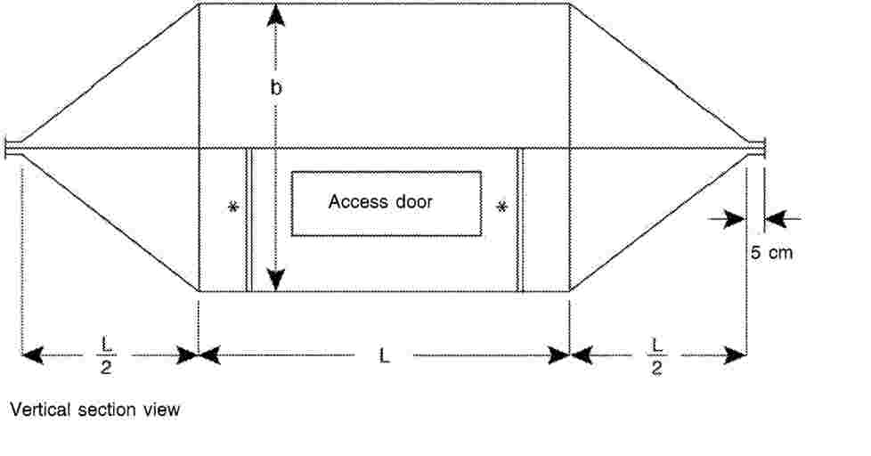
The following table shows the dimensions for constructing a cell with specified upper frequency limits:
|
Upper frequency (MHz) |
Cell form factor W: b |
Cell form factor L/W |
Plate separation b (cm) |
Septum S (cm) |
|
200 |
1,69 |
0,66 |
56 |
70 |
|
200 |
1,00 |
1,00 |
60 |
50 |
14. Free field ESA immunity test
Figure 8
Test layout (general plan view)

Figure 9
View of test bench plane of longitudinal symmetry

PART 9
Manufacturers may choose whether to apply either the requirements of Parts 2 to 8 or the requirements of UNECE Regulation No 10 as referenced in Annex I or the requirements of ISO 14982: 1998.
(1) If applicable.
(2) If applicable.
ANNEX XVI
Requirements on audible warning devices
1. The audible warning device shall be granted component type-approval according to the requirements for N-category vehicles in the UNECE Regulation No 28 as referenced in Annex I.
2. Characteristics of the audible warning device when fitted to the tractor
2.1. Acoustic tests
When a tractor is type approved, the characteristics of the warning device fitted to that type of tractor shall be tested as follows:
|
2.1.1. |
The sound pressure level of the device when fitted to the tractor shall be measured at a point 7 metres in front of the tractor, at a site which is open and as level as possible. The engine of the tractor shall be stopped. The effective voltage shall be that laid down in paragraph 6.2.3 of UNECE Regulation No 28 as referenced in Annex I. |
|
2.1.2. |
Measurements shall be made on the ‘A’ weighting scale of the IEC (International Electrotechnical Commission) standard. |
|
2.1.3. |
The maximum sound pressure level shall be determined at a height between 0,5 and 1,5 metres above ground level. |
|
2.1.4. |
The maximum value for the sound-pressure level shall be at least 93 dB(A) and at the most 112 dB(A). |
ANNEX XVII
Requirements on heating systems
1. Requirements for all T- and C-category vehicles, where such system is fitted
|
1.1. |
Tractors with enclosed driver compartments shall be fitted with a heating system which complies with this Annex. Tractors with enclosed driver compartments may be fitted with air conditioning systems; where fitted, such systems shall comply with this Annex. |
|
1.2. |
The heating system, in combination with the enclosed compartment ventilation, shall be able to defrost and demist the windscreen. Heating and cooling systems shall be tested in accordance with ISO 14269-2:1997, sections 8 and 9, respectively. Test reports shall be included into the information document. |
|
1.3. |
The manufacturer may choose whether to comply with either the requirements set out in this Annex on heating system or with the requirements for N-category vehicles set out in UNECE Regulation No 122 as referenced in Annex I. |
ANNEX XVIII
Requirements on devices to prevent unauthorised use
1. Requirements for all T- and C-category vehicles
Manufacturers may choose to apply either this point or point 2.
1.1. Starting and stopping the engine
|
1.1.1. |
A means shall be provided to enable prevention of inadvertent and/or unauthorised starting of the engine. Examples of such means include but are not limited to:
|
2. Requirements for all T- and C-category vehicles according to UNECE regulations or international standards
|
2.1. |
For vehicles which are fitted with handlebars, all the relevant requirements of UNECE Regulation No 62, as referenced in Annex I, shall apply. |
|
2.2. |
For vehicles which are not fitted with handlebars, manufacturers shall apply all the relevant requirements as prescribed for vehicle category N2 in points 2, 5 except point 5.6, 6.2 and 6.3, of UNECE Regulation No 18, as referenced in Annex I to this Regulation or the requirements of appropriate standards on programmable electronic devices in order to prevent unauthorised use, should such standards exist from 1 January 2018. |
3. Requirements for all S-category vehicles and interchangeable towed equipment falling in R-category due to technically permissible maximum laden mass to the unladen mass equal to or greater than 3,0
At least one device shall be installed on a S-category vehicle or interchangeable towed equipment falling in R-category due to technically permissible maximum laden mass to the unladen mass equal to or greater than 3,0 to enable prevention of inadvertent or unauthorised use of such vehicles.
Such device may consist in the following:
|
— |
a lockable cover over the coupling device, |
|
— |
a chain and padlock through the ring of the coupling device, |
|
— |
a wheel clamp, |
|
— |
a padlock in a hole in the sector of the park brake; |
The Operator’s Manual shall contain information on the use of the devices installed on the vehicle.
ANNEX XIX
Requirements on registration plates
1. Shape and dimensions of the space for mounting rear registration plates
The space for mounting shall comprise a flat or virtually flat rectangular surface with the following minimum dimensions:
|
|
either
|
|
|
or
|
2. Location of the space for mounting and the fixing of the plates
The space for mounting shall be such that, after correct fixing, the plates shall have the following characteristics:
2.1. Lateral position of the plate
The centre of the plate shall not be further to the right than the plane of symmetry of the vehicle. The left lateral edge of the plate shall not be further to the left than the vertical plane parallel to the plane of symmetry of the vehicle and tangent to the point where the cross section of the vehicle is at its widest.
2.2. Position of the plate in relation to the longitudinal plane of symmetry of the vehicle
The plate shall be perpendicular or practically perpendicular to the plane of symmetry of the vehicle.
2.3. Position of the plate in relation to the vertical plane
The plate shall be vertical within a tolerance of 5°. However, where the shape of the vehicle so requires, it may be inclined to the vertical:
|
2.3.1. |
at not more than 30° when the surface bearing the registration number is inclined upwards, provided that the height of the upper edge of the plate is not more than 1,2 metres from the ground. |
|
2.3.2. |
at not more than 15° when the surface bearing the registration number is inclined downwards, provided that the height of the upper edge of the plate is more than 1,2 metres from the ground. |
2.4. Height of the plate from the ground
The height of the lower edge of the plate above ground shall not be less than 0,3 metres; the height of the upper edge of the plate above ground shall not exceed 4 metres.
2.5. Determination of the height of the plate from the ground
The heights given in points 2.3 and 2.4 shall be measured with the vehicle unladen.
2.6. Geometrical visibility:
|
2.6.1. |
The plate shall be visible in the whole space within the following four planes:
|
|
2.6.2. |
No structural element, even when fully transparent, shall be located in the space described above. |
ANNEX XX
Requirements on statutory plates and markings
1. Definitions
For the purposes of this Annex:
|
1.1. |
‘Statutory plate’ means the plate that the manufacturer shall affix to each vehicle manufactured in conformity with the approved type as set out in Article 34 of Regulation (EU) No 167/2013 and it shall have the appropriate marking in accordance with this Annex. |
|
1.2. |
‘Statutory markings’ means any mandatory markings together with the type-approval mark set out in Article 34 of Regulation (EU) No 167/2013 which, in accordance with this Annex, shall be affixed to vehicles, components or separate technical units when they are manufactured in conformity with the approved type or for its identification during the type approval processes. |
2. General
|
2.1. |
All agricultural or forestry vehicles shall be provided with the plate and inscriptions described in the following points. The plate and inscriptions are attached either by the manufacturer or by his authorised representative. |
|
2.2. |
All components or separate technical units conforming to a type approved pursuant to Regulation (EU) No 167/2013 shall bear an EU type-approval mark described in point 6 or a mark according to Article 34(2) of Regulation (EU) No 167/2013 set out in Article 68(h) or Article 34(3), respectively, of Regulation (EU) No 167/2013. |
3. Statutory plate
|
3.1. |
A statutory plate, modelled as set out in Article 34(3) of Regulation (EU) No 167/2013, shall be firmly attached in a conspicuous and readily accessible position on a part normally not subject to replacement during normal use, regular maintenance or repair (e.g. due to accident damage). It shall show clearly and indelibly the information specified in the model for the EU type-approval mark set out in Article 34(3) or in Article 68(h) of Regulation (EU) No 167/2013. |
|
3.2. |
The manufacturer may give additional information below or to the side of the prescribed inscriptions, outside a clearly marked rectangle enclosing only the information prescribed in accordance with Article 34(1) and (3) of Regulation (EU) No 167/2013. |
4. Vehicle Identification Number
The vehicle identification number is a fixed combination of characters unequivocally attributed to a particular vehicle by the manufacturer. Its purpose is to ensure that every vehicle, and in particular its type, can be clearly identified over a period of 30 years through the intermediary of the manufacturer, without a need for further reference.
The identification number shall comply with the following requirements:
|
4.1. |
The VIN shall be marked on the statutory plate, as well as on the chassis, frame or a similar structure of the vehicle when the vehicle leaves the production line. |
|
4.2. |
It shall wherever possible be entered on a single line. |
|
4.3. |
It shall be marked on the chassis or other similar structure, on the front right-hand side of the vehicle. |
|
4.4. |
It shall be hammered, punched, etched or laser-engraved directly onto an easily accessible part, preferably on the front right side of the vehicle in a way which avoids obliteration, alteration and removal. |
5. Characters
The characters that shall be used for the markings of points 3 and 4 are specified in the model for the EU type-approval mark set out in Article 68(h) of Regulation (EU) No 167/2013.
6. Marking requirements for components and separate technical units
Every separate technical unit or component, conforming to a type in respect of which EU separate technical unit or component type-approval has been granted in accordance with Chapter V of Regulation (EU) No 167/2013, shall bear an EU separate technical unit or component type-approval mark, pursuant to Article 34(2) and (3) of Regulation (EU) No 167/2013. The markings shall be visible when installed on the vehicle without the need to remove any parts with the use of tools and shall be durably affixed (e.g. stamped, etched, laser inscribed, self-destructing adhesive label).
ANNEX XXI
Requirements on dimensions and trailer masses
1. Definitions
For the purposes of this Annex:
|
1.1. |
‘Length of the vehicle’ means:
|
|
1.2. |
‘Width of the vehicle’ means:
|
|
1.3. |
‘Height of the vehicle’ means the vertical distance between the ground and the point on the vehicle the greatest distance from the ground, excluding the aerial. When this height is determined, the vehicle must be fitted with new tyres having the greatest rolling radius, expressed by the speed radius index, specified by their manufacturer; |
|
1.4. |
‘Permissible towable mass’ means the mass which a type of tractor may tow; |
|
1.5. |
‘Technically permissible towable mass(es)’ means one of the following:
|
Requirements
Vehicles may not exceed the dimensions and masses laid down below:
2. Dimensions
The measurements intended to check these dimensions shall be carried out as follows:
|
— |
with unladen mass of vehicle in running order, |
|
— |
on a flat horizontal surface, |
|
— |
with the vehicle stationary and, if applicable, the engine switched off, |
|
— |
with the new tyres at the normal pressure recommended by the manufacturer, |
|
— |
with doors and windows closed, if applicable, |
|
— |
with the steering wheel in the straight-ahead position, if applicable, |
|
— |
without any detachable agricultural or forestry implement attached to the vehicle and that can be detached without special tools. |
|
2.1. |
The maximum dimensions of any vehicle of category T, C or R are as follows:
|
|
2.2. |
The maximum dimensions of any vehicle of category S are as follows:
|
3. Permissible towable mass
|
3.1. |
The permissible towable mass may consist of one or more trailers towed or agricultural or forestry implements. A distinction is drawn between the technically permissible towable mass stated by the manufacturer and the permissible towable mass as laid down in point 3.2 below. |
|
3.2. |
The permissible towable mass shall not exceed:
|
ANNEX XXII
Requirements on the maximum laden mass
1. Definitions
For the purposes of this Annex:
Definitions of ‘drawbar towed vehicle’ and ‘rigid drawbar towed vehicle’, in accordance with the requirements laid down on the basis of Article 17(2)(b) and (4) of Regulation (EU) No 167/2013, are valid for this Annex.
|
1.1. |
‘Technically permissible maximum laden mass’ means the maximum mass allocated to a vehicle on the basis of its construction features and its design performances irrespective from the load capacity of the tyres or tracks. |
|
1.2. |
‘Technically permissible maximum mass per axle’ means the mass corresponding to the maximum permissible static vertical load transmitted to the ground by the wheels of the axle, on the basis of the construction features of the axle and of the vehicle and their design performances irrespective from the load capacity of the tyres or tracks. |
2. Requirements
2.1. The technically permissible maximum laden mass as stated by the manufacturer shall be accepted by the type-approval authority as the maximum permissible laden mass provided that:
|
2.1.1. |
the results of any tests which that administration makes, in particular those in respect of braking and steering, are satisfactory; |
|
2.1.2. |
the technically permissible maximum laden mass and the technically permissible maximum mass per axle depending on the vehicle category does not exceed the values given in Table 1. Table 1 Maximum permissible laden mass and maximum permissible mass per axle depending on the vehicle category
|
||||||||||||||||||||||||||||||||||||||||||||||||||||||||||||||||||||||
2.2. Whatever the state of loading of the tractor, the mass transmitted to the road by the wheels on the steering axle shall not be less than 20 % of the unladen mass of that tractor.
2.3. Sum of the technically permissible maximum masses per axle
|
2.3.1. |
For vehicles of categories T and C and of categories R and S, which do not impose any significant static vertical load on the tractor (drawbar towed vehicle), the sum of the maximum permissible masses per axle shall be equal to or higher than the maximum permissible laden mass of the vehicle. |
|
2.3.2. |
For vehicles of categories R and S imposing a significant static vertical load on the tractor (rigid drawbar towed vehicle), the maximum permissible mass of the vehicle shall be considered to be the sum of the maximum permissible masses per axle and shall be applicable for type approval purposes. |
(1) It is not necessary to establish an axle limit for vehicle categories T3 and T4.3, as they have by definition limitations on the maximum permissible laden and/or unladen mass.
(2) The corresponding value for the sum of the axle maximum permissible mass is the sum of the axle weights in Annex I, points 3.1 to 3.3, to Council Directive 96/53/EC (Council Directive 96/53/EC of 25 July 1996 laying down for certain road vehicles circulating within the Community the maximum authorised dimensions in national and international traffic and the maximum authorised weights in international traffic (OJ L 235, 17.9.1996, p. 59).
(3) Where the driving axle is fitted with twin tyres and air suspension or suspension recognised as being equivalent within the European Union as defined in Annex II to Directive 96/53/EC, or where each driving axle is fitted with twin tyres and the maximum weight of each axle does not exceed 9,5 t.
(4) The corresponding value for the sum of the axle maximum permissible mass is the sum of the axle weights in Annex I, point 3.5, to Directive 96/53/EC.
ANNEX XXIII
Requirements on ballast masses
Where the tractor is to be fitted with ballast weights in order to meet the other requirements of EU type-approval, those ballast weights shall be supplied by the manufacturer of the tractor, be intended for fitting, and bear the manufacturer’s mark and a statement of their mass in kilograms to an accuracy of ± 5 %. Front ballast weights that have been designed for frequent removal/fitting shall leave a safety clearance of at least 25 mm for the grab handles. The method of locating the ballast weights shall be such that any inadvertent separation is avoided (e.g. in the event of tractor rollover).
ANNEX XXIV
Requirements on the safety of electrical systems
1. Requirements for all T, C, R and S vehicles equipped with electrical systems
1.1. Electrical equipment
|
1.1.1. |
Electrical cables shall be protected if located in potentially abrasive contact with surfaces and shall be resistant to, or protected against, contact with lubricant or fuel. Electrical cables shall be located so that no portion is in contact with the exhaust system, moving parts or sharp edges. |
|
1.1.2. |
Fuses or other overload protection devices shall be installed in all electrical circuits except for high amperage circuits such as the starter-motor circuit and high-tension spark ignition system. Electrical distribution of these devices between circuits shall prevent the possibility of cutting off all operator alert systems simultaneously. |
2. Requirements on static electricity safety
Requirements on static electricity safety are the ones provided in point 3 of Annex XXV.
3. All-electric vehicles in categories T2, T3, C2 or C3 should comply, as far as is practicable, with the requirements of Annex IV of Commission Delegated Regulation (EU) No 3/2014 (1).
(1) Commission Delegated Regulation (EU) No 3/2014 of 24 October 2013 supplementing Regulation (EU) No 168/2013 of the European Parliament and of the Council with regard to vehicle functional safety requirements for the approval of two- or three-wheel vehicles and quadricycles (OJ L 7, 10.1.2014, p. 1).
ANNEX XXV
Requirements on fuel tanks
1. This Annex applies to tanks designed to contain the liquid fuel used primarily for the propulsion of the vehicle.
Fuel tanks shall be made so as to be corrosion resistant. They shall satisfy the leakage tests carried out by the manufacturer at a pressure equal to double the working pressure but in any event not less than 0,3 bar. Any excess pressure or any pressure exceeding the working pressure shall be automatically compensated by suitable devices (vents, safety valves etc.). The vents shall be designed in such a way as to prevent any fire risk. The fuel shall not escape through the fuel-tank cap or through the devices provided to compensate excess pressure even if the tank is completely overturned: a drip shall be tolerated.
2. Fuel tanks shall be installed in such a way as to be protected from the consequences of an impact to the front or to the rear of the tractor; there shall be no protruding parts, sharp edges etc. near the tanks.
The fuel supply pipework and the filler orifice shall be installed outside the cab.
3. Requirements related to static electricity safety of the fuel tank
The fuel tank and its accessory parts shall be designed and installed in the vehicle in such a way that any ignition hazard due to static electricity shall be avoided.
If necessary, measure(s) for charge dissipation shall be provided.
The manufacturer shall demonstrate to the Technical Service the measure(s) which guarantee the fulfilling of these requirements.
ANNEX XXVI
Requirements on rear protective structures
1. General
Vehicles of category R covered by this Regulation shall be designed so as to provide effective protection against underrunning from the rear by vehicles of categories M1 and N1 (1). They shall comply with the requirements of points 2 and 3, shall be granted a type-approval certificate set out in Article 68(c) of Regulation (EU) No 167/2013 and the EU type-approval mark shall be affixed to them as set out in Article 68(h) of Regulation (EU) No 167/2013.
2. Requirements
|
2.1. |
Vehicles of categories Ra and Rb shall be so constructed and/or equipped as to offer effective protection over their whole width against underrunning from the rear by a vehicle of categories M1 and N1.
|
|
2.2. |
Any vehicle in one of the categories R1a, R1b, R2a or R2b shall be deemed to satisfy the condition set out in 2.1:
Where there is more than one rear axle, the width to be considered is that of the widest. This requirement shall be satisfied at least on a line at a distance of not more than 45 cm from the rear extremity of the vehicle. |
|
2.3. |
Any vehicle in one of the categories R3a, R3b, R4a or R4b shall be deemed to satisfy the condition set out in 2.1 provided that:
|
|
2.4. |
A device for protection against underrunning from the rear, hereinafter referred to as ‘device’, generally consists of a cross-member and linking components connected to the chassis side-members or to whatever replaces them.
It shall have the following characteristics:
|
|
2.5. |
By way of derogation from the abovementioned requirements, vehicles of the following categories need not comply with the requirements of this Annex as regards rear underrun protection:
|
3. Exemptions
Vehicles where any rear protective structure is incompatible with their rear fitted operational devices, shall be exempted from the requirement. Otherwise, the vehicle shall be fitted with a rear protective structure at its rear part that does not obstruct the function of those operational devices.
(1) As defined in Annex II Part A to Directive 2007/46/EC.
(2) As defined in item 2.6 of Appendix 1.
ANNEX XXVII
Requirements on lateral protection
1. General prescriptions
1.1. Every vehicle of categories R3b and R4b shall be so constructed and /or equipped as to offer, when a complete entity, effective protection to unprotected road users (pedestrians, cyclists, motorcyclists) against the risk of falling under the sides of the vehicle and being caught under the wheels.
This Annex shall not apply to:
|
— |
trailers specially designed and constructed for the carriage of very long loads of indivisible length, such as timber, |
|
— |
vehicles designed and constructed for special purposes where it is not possible, for practical reasons, to fit such lateral protection. |
1.2. A vehicle satisfies the requirement set out in point 1.1 if its side parts provide protection conforming to the provisions of the points 1.3.–5 and of Appendix 1.
1.3. Positioning of the vehicle for testing its compliance to lateral protection
When tested for compliance with the technical specifications set out in point 2, the position of the vehicle shall be as follows:
|
— |
on a horizontal and flat surface, |
|
— |
the steered wheels shall be in a straight-ahead position, |
|
— |
the vehicle shall be unladen, |
|
— |
semi-trailers shall be positioned on their supports with the loading surface horizontal. |
2. Lateral protection provided by a specific device (side guard)
|
2.1. |
The device shall not increase the overall width of the vehicle and the main part of its outer surface shall not be more than 120 mm inboard from the outermost plane (maximum width) of the vehicle. Its forward end may be turned inwards on some vehicles in accordance with points 2.4.2 and 2.4.3. Its rearward end shall not be more than 30 mm inboard from the outermost edge of the rear tyres (excluding any bulging of the tyres close to the ground) over at least the rearmost 250 mm. |
|
2.2. |
The outer surface of the device shall be smooth, substantially flat or horizontally corrugated and so far as possible continuous from front to rear; adjacent parts may however overlap, provided that the overlapping edge faces rearwards or downwards, or a gap of not more than 25 mm measured longitudinally may be left, provided that the rearward part does not protrude outboard of the forward part; domed heads of bolts or rivets may protrude beyond the surface to a distance not exceeding 10 mm and other parts may protrude to the same extent provided that they are smooth and similarly rounded; all external edges and corners shall be rounded with a radius not less than 2,5 mm (tested as prescribed in Appendix 1). |
|
2.3. |
The device may consist of a continuous flat surface, or of one or more horizontal rails, or a combination of surface and rails; when rails are used, they shall be not more than 300 mm apart and not less than:
|
|
2.4. |
The forward edge of the side guard shall be constructed as follows:
|
|
2.5. |
The rearward edge of the side guard shall not be more than 300 mm forward of the transverse vertical plane tangential to the foremost part of the tyre on the wheel immediately to the rear; a continuous vertical member is not required on the rear edge. |
|
2.6. |
The lower edge of the side guard shall at no point be more than 550 mm above the ground. |
|
2.7. |
The upper edge of the guard shall not be more than 350 mm below that part of the structure of the vehicle, cut or contacted by a vertical plane tangential to the outer surface of the tyres, excluding any bulging close to the ground, except in the following cases:
|
|
2.8. |
Side guards shall be essentially rigid, securely mounted (they shall not be liable to loosening due to vibration in normal use of the vehicle) and made of metal or any other suitable material. The side guard shall be considered suitable if it is capable of withstanding a horizontal static force of 1 kN applied perpendicularly to any part of its external surface by the centre of a ram the face of which is circular and flat, with a diameter of 220 mm ± 10 mm, and if the deflection of the guard under load is then not more than:
|
|
2.9. |
The side guard may not be used for the attachment of brake, air or hydraulic pipes. |
3. By derogation from the above provisions, vehicles of the following types need comply only as indicated in each case:
|
3.1. |
An extendible trailer shall comply with all of the requirements of point 2, when closed to its minimum length; when the trailer is extended, the side guards shall comply with points 2.6, 2.7 and 2.8, and with either 2.4 or 2.5 but not necessarily both; extension of the trailer shall not produce gaps in the length of the side guards; |
|
3.2. |
a tank-vehicle that is a vehicle designed solely for the carriage of fluid substance in a closed tank permanently fitted to the vehicle and provided with hose or pipe connections for loading or unloading, shall be fitted with side guards which comply so far as is practicable with all the requirements of point 2; strict compliance may be waived only where operational requirements make this necessary; |
|
3.3. |
On a vehicle fitted with extendible legs to provide additional stability during loading, unloading or other operations for which the vehicle is designed, the side guard may be arranged with additional gaps where these are necessary to permit extension of the legs. |
4. If the sides of the vehicle are so designed and/or equipped that by their shape and characteristics their component parts together meet the requirements of point 2, they may be regarded as replacing the side guards.
5. Alternative requirements
Alternatively to complying with points 1.3 to 2.9 and point 4., manufacturers may choose whether to comply with points 2 and 3 and Parts I, II and III as well as Annex 3 of UNECE Regulation No 73 as referenced in Annex I.
Appendix 1
Method for determining the height of external surface projections
|
1. |
The height H of a projection is determined graphically by reference to the circumference of a 165 mm diameter circle, internally tangential to the external outline of the external surface at the section to be checked. |
|
2. |
H is the maximum value of the distance, measured along a straight line passing through the centre of the 165 mm diameter circle, between the circumference of the aforesaid circle and the external contour of the projection (see Figure 1). |
|
3. |
In cases where it is not possible for a 100 mm diameter circle to contact externally part of the external outline of the external surface at the section under consideration, the surface outline in this area shall be assumed to be that formed by the circumference of the 100 mm diameter circle between its tangent points with the external outline (see Figure 2). |
|
4. |
Drawings of the necessary sections through the external surface shall be provided by the manufacturer to allow the height of the projections referred to above to be measured. |
Figure 1

Figure 2
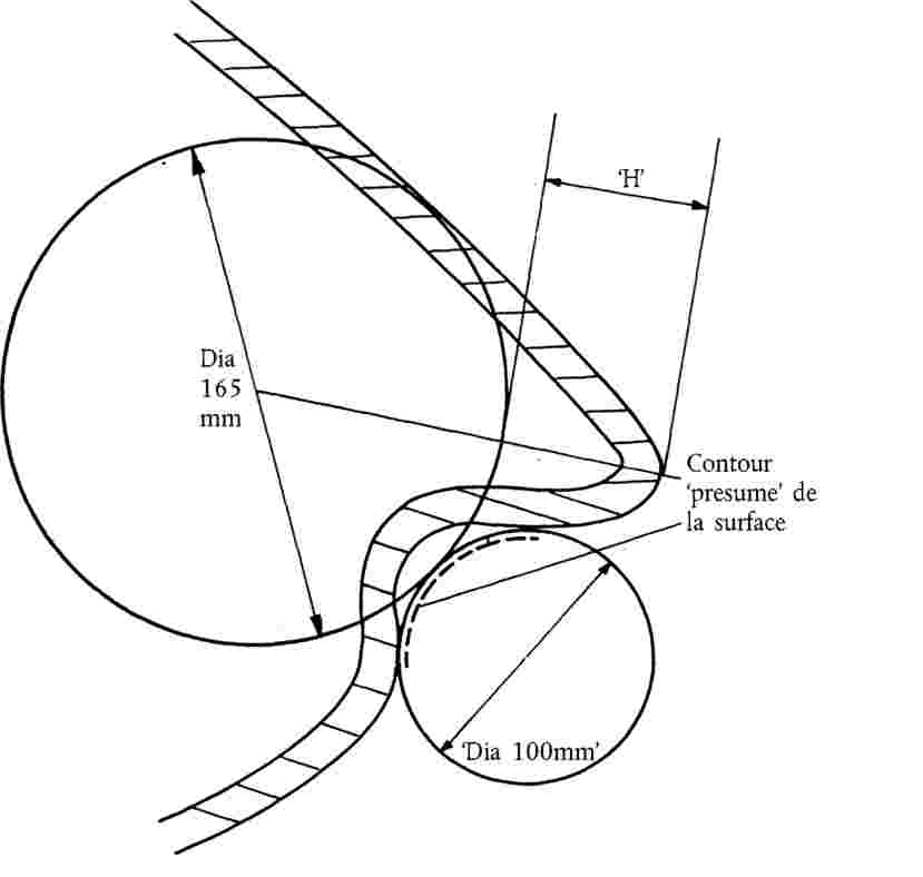
ANNEX XXVIII
Requirements on load platforms
|
1. |
The centre of gravity of the platform shall be situated between the axles. |
|
2. |
The dimensions of the platform shall be such that:
|
|
3. |
The platform shall be laid out symmetrically in relation to the longitudinal median plane of the tractor. |
|
4. |
The height of the load platform above the ground shall be not more than 150 cm. |
|
5. |
The type of platform and the way it is fitted shall be such that, with a normal load, the driver’s field of vision remains adequate and the various compulsory lighting and light-signalling devices may continue to fulfil their proper function. |
|
6. |
The load platform may be detachable; it shall be attached to the tractor in such a way as to avoid any risk of accidental detachment. |
|
7. |
For tractors of category T4.3, the length of the platform shall not exceed 2,5 times the maximum front or rear track of the tractor, whichever is the larger. |
|
8. |
For vehicles with multiple load platforms, the centre of gravity of the vehicle with loaded platform(s) and without driver shall be situated between the front-most and the rearmost axle in all loading conditions. Any load shall be evenly distributed on the load platform(s). |
ANNEX XXIX
Requirements on towing devices
1. Number
Every tractor shall have a special device to which it shall be possible to attach a connection such as a tow-bar or a tow-rope for towing purposes.
2. Position
The device shall be fitted to the front of the tractor, which shall be equipped with a coupling pin or hook.
3. Design
The towing device shall be of the slotted-jaw type or a winch suitable for its application. The opening at the centre of the locking pin shall be 60 mm + 0,5/– 1,5 mm and the depth of the jaw measured from the centre of the pin shall be 62 mm ± 0,5 mm.
The coupling pin shall have a diameter of 30 + 1,5 mm and be fitted with a device preventing it from leaving its seating during use. The securing device shall be non-detachable.
The tolerance of + 1,5 mm referred to above should not be regarded as a manufacturing tolerance but as a permissible variation in nominal dimensions for pins of different designs.
4. Alternative requirements
|
4.1. |
The dimensions of point 3 can be exceeded if the manufacturer deems that they are not adequate for the size or mass of the vehicle. |
|
4.2. |
Manufacturers may choose to apply on vehicles with a maximum technically permissible mass not exceeding 2 000 kg either the requirements of points 1, 2 and 3 or the requirements of Commission Regulation (EU) No 1005/2010 (1). |
5. Instructions
The correct use of the towing device shall be explained in the Operator’s manual, in accordance with the requirements laid down on the basis of Article 18(2)(l), (n), (q) and (4) of Regulation (EU) No 167/2013.
(1) Commission Regulation (EU) No 1005/2010 of 8 November 2010 concerning type-approval requirements for motor vehicle towing devices and implementing Regulation (EC) No 661/2009 of the European Parliament and of the Council concerning type- approval requirements for the general safety of motor vehicles, their trailers and systems, components and separate technical units intended therefor (OJ L 291, 9.11.2010, p. 36).
ANNEX XXX
Requirements on tyres
1. Definitions
For the purposes of this Annex:
|
1.1. |
‘Cyclic service’ means the condition that applies when the load on the tyre cycles between the fully loaded and the unloaded condition; |
|
1.2. |
‘High and sustained torque’ means the condition that occurs due to a load on the drawbar or hitch; |
|
1.3. |
‘Applicable tyre inflation pressure’ means the internal pressure of the tyre, with the tyre at ambient temperature (i.e. cold tyre pressure), recommended in conformity to the load, speed and service conditions of the vehicle. It does not include any pressure built up due to tyre usage and is expressed in kPa; |
|
1.4. |
‘Maximum load rating’ means the mass which a tyre can carry when operated in conformity with requirements governing utilisation specified by the tyre manufacturer; |
|
1.5. |
‘Maximum permissible mass per axle according to tyre specification’ means the mass corresponding to the maximum permissible static vertical load that can be transmitted to the ground by the wheels of the axle as restricted by the maximum load rating of tyre types that can be fitted to the vehicle as listed in the information document. |
2. Requirements
2.1. Requirements applying to the component type-approval of tyres
2.1.1. Provisions for pneumatic tyres designed primarily for agricultural vehicles with diagonal or bias-ply and bias-belted construction with a reference speed not exceeding 40 km/h (i.e. speed symbol A8), as well as radial tyres designed primarily for construction application purposes (i.e. tyres marked ‘Industrial’, ‘IND’, ‘R-4’ or ‘F-3’).
2.1.1.1. All tyres conforming to the relevant type shall be marked in conformity with points 2.1.1.2 to 2.1.1.2.4.
2.1.1.2. Specific requirements for markings.
2.1.1.2.1. Tyres shall bear the following markings, in conformity with ISO 4223-1:2002/Amd 1:2011, including:
|
— |
the tyre size designation; |
|
— |
the load capacity index (i.e. a numerical code which indicates the load the tyre can carry at the speed corresponding to the associated speed category); |
|
— |
the speed category symbol (i.e. a symbol which indicates the maximum speed at which the tyre can carry the load corresponding to its load index); and |
|
— |
the word ‘TUBELESS’ if the tyre is designed for use without an inner tube. |
2.1.1.2.2. Tyres shall bear the following additional markings:
|
— |
the manufacturer's trade name or mark; |
|
— |
the inflation pressure that shall not be exceeded for the purpose of bead seating during tyre mounting; |
|
— |
in case of implement tyres the service description (i.e. load index and speed category symbol) shall be supplemented with the indication whether it applies to ‘drive wheel’ or to ‘free rolling wheel’ or to both; and |
|
— |
the date of manufacture in the form of a group of four digits, the first two showing the week and the last two the year of manufacture. |
2.1.1.2.3. All markings mentioned in points 2.1.1.2.1 and 2.1.1.2.2 shall be legibly and permanently moulded into or onto the sidewall and produced as part of the process during manufacture. The use of branding or other methods of marking after completion of the original manufacturing process is not permitted.
2.1.1.2.4. In line with Article 34(2) of Regulation (EU) No 167/2013, no type-approval mark is required for pneumatic tyres designed primarily for agricultural vehicles with diagonal or bias-ply and bias-belted construction with a reference speed not exceeding 40 km/h (i.e. speed symbol A8), as well as radial tyres designed primarily for construction application purposes (i.e. tyres marked ‘Industrial’, ‘IND’, ‘R-4’ or ‘F-3’) approved in accordance with this Regulation.
The information document and information folder that shall be submitted with the application for type-approval of those tyres are specified in the models set out in Article 68(a) of Regulation (EU) No 167/2013.
A unique type-approval number, the model of which is set out in Article 68(h) of Regulation (EU) No 167/2013, shall be assigned to each type-approved tyre and a type-approval certificate, the model of which is set out in Article 68(c) of Regulation (EU) No 167/2013, shall be issued.
2.1.2. New pneumatic tyres conforming to the type complying with the requirements set out in points 2.1.1. to 2.1.1.2.4 may continue to be placed on the market until 31 December 2018.
2.1.2.1. Tyres that were manufactured prior to the date set out in point 2.1.2. which do not comply with the requirements of points 2.1.3. to 2.1.3.1. and which comply with the requirements set out in points 2.1.1. to 2.1.1.2.4. may be sold for a period not exceeding 30 months from that date.
2.1.3. Requirements for pneumatic tyres designed primarily for agricultural vehicles other than those set out in points 2.1.1. to 2.1.1.2.4.
2.1.3.1. Tyres not covered by the provisions of points 2.1.1 to 2.1.1.2.4. shall conform to the types approved under the relevant UNECE regulations.
2.2. Requirements for the approval of a type of vehicle with regard to the installation of tyres
2.2.1. Specific requirements for the installation of tyres on vehicles with a maximum design speed not exceeding 65 km/h.
2.2.1.1. Subject to the provisions of point 2.2.1.2. all tyres fitted to vehicles, including any spare tyre, shall be type-approved according to UNECE Regulation No 106 as referenced in Annex I.
2.2.1.1.1. For the purpose of vehicle type-approval in accordance with Regulation (EU) No 167/2013, tyres designed primarily for agricultural vehicles with diagonal or bias-ply and bias-belted construction with a reference speed not exceeding 40 km/h (i.e. speed symbol A8), as well as radial tyres designed primarily for construction application purposes (i.e. tyres marked ‘Industrial’, ‘IND’, ‘R-4’ or ‘F-3’) may until 31 December 2017 be type-approved according to this Regulation instead.
2.2.1.2. Where a vehicle is designed for conditions of use which are incompatible with the characteristics of tyres type-approved according to UNECE Regulation No 106, as referenced in Annex I, or this Regulation and it is therefore necessary to fit tyres with different characteristics, the requirements of point 2.2.1.1. do not apply, provided that the following conditions are met:
|
— |
the tyres are in accordance with Regulation (EC) No 661/2009 of the European Parliament and of the Council (1) (i.e. type-approved according to UNECE regulations Nos 30, 54 and 117 as referenced in Annex I to this Regulation) or type-approved according to UNECE Regulation No 75, as referenced in Annex I, and |
|
— |
the approval authority and technical service are satisfied that the tyres fitted are suitable for the operating conditions of the vehicle. The nature of the exemption and reasons for acceptance shall be clearly stated in the test report. |
2.2.2. Specific requirements for the installation of tyres on vehicles with a maximum design speed exceeding 65 km/h.
2.2.2.1. Subject to the provisions of point 2.2.2.2., all tyres fitted to vehicles, including any spare tyre, shall be in accordance with Regulation (EC) No 661/2009 (i.e. type-approved according to UNECE Regulations Nos 30, 54 and 117 as referenced in Annex I).
2.2.2.2. Where a vehicle is designed for conditions of use which are incompatible with the characteristics of tyres type-approved in accordance with Regulation (EC) No 661/2009 and it is therefore necessary to fit tyres with different characteristics, the requirements of point 2.2.2.1. do not apply, provided that the following conditions are met:
|
— |
the tyres are type-approved according to UNECE Regulation No 75; as referenced in Annex I, and |
|
— |
the approval authority and technical service are satisfied that the tyres fitted are suitable for the operating conditions of the vehicle. The nature of the exemption and reasons for acceptance shall be clearly stated in the test report. |
2.2.3. General requirements for the installation of tyres
2.2.3.1. All tyres normally fitted to one axle shall be of the same type, with the exception of the cases mentioned in points 2.2.4.1.1 and 2.2.4.1.2.
2.2.3.2. The space in which the wheel revolves shall be such as to allow unrestricted movement when using the maximum permissible size of tyres and rim widths, taking into account the minimum and maximum wheel off-sets if applicable, within the minimum and maximum suspension and steering constraints as declared by the vehicle manufacturer. This shall be verified by performing the checks with the largest and the widest tyres in each space, taking into account the applicable rim size and the maximum allowed section width and outer diameter of the tyre, in relation to the tyre size designation as specified in the relevant UNECE regulation. The checks shall be performed by rotating a representation of the tyre’s maximum envelope, not just the actual tyre, in the space for the wheel in question.
2.2.3.3. The technical service may agree to an alternative test procedure (e.g. virtual testing) to verify that the requirements of point 2.2.3.2 are met, provided that the clearance between the tyre’s maximum envelope and vehicle structure is complied with.
2.2.4. Load capacity
2.2.4.1. The maximum load rating of each tyre fitted on the vehicle, taking into due account the maximum design speed of the vehicle and the most demanding service conditions, as well as the special cases of points 2.2.6. to 2.2.6.5. if applicable, shall be at least equal to the following:
|
— |
the maximum permissible mass per axle where the axle is equipped with one tyre only; |
|
— |
half of the maximum permissible mass per axle where the axle is equipped with two tyres in single formation; |
|
— |
0,285 times the maximum permissible mass per axle where the axle is equipped with two sets of tyres in dual (twin) formation; |
|
— |
0,20 times the maximum permissible mass per axle where the axle is equipped with two sets of tyres in triple formation. |
2.2.4.1.1. In case where dual or triple formations are composed by tyres of different types (i.e. tyre size designations and service descriptions) the following apply:
|
— |
the tyres shall have the same overall diameter; |
|
— |
the tyres shall be of the same ‘category of use’, ‘structure’ and ‘speed category symbol’ as defined in paragraphs 2.1.3, 2.1.4 and 2.1.5 of UNECE regulation 106, as referenced in Annex I; |
|
— |
the vehicle shall be equipped symmetrically; |
|
— |
the sum of the maximum load ratings of all tyres fitted to the axle shall be at least 1,14 times the maximum permissible axle mass in the case of dual formation and 1,2 times the maximum permissible axle mass in the case of triple formation; |
|
— |
the share of the maximum permissible mass per axle on each tyre of the formation shall not exceed the maximum load rating of each tyre; |
|
— |
the inflation pressure of each tyre in the formation shall conform to the recommendation of the tyre manufacturer taking into account the actual load on each tyre and the service conditions. |
2.2.4.1.2. When a vehicle may be fitted on each axle with tyres for which the sum of maximum load rating is less than the maximum permissible mass per axle, the requirements of points 2.2.4.1 and 2.2.4.1.1 apply with the maximum permissible mass per axle according to the tyre specification instead of the maximum permissible mass per axle.
The maximum permissible mass per axle according to the tyre specification and the maximum permissible mass per axle are the ones declared by the vehicle manufacturer.
The owner’s manual, the information document and the certificate of conformity shall mention the values of mass per axle for each one of them depending on the maximum permissible mass per axle according to the tyre specification.
2.2.4.2. The maximum load rating of a tyre is determined as follows:
|
2.2.4.2.1. |
In the case of tyres identified by speed symbol D (i.e. 65 km/h) or lower the ‘table load-capacity variation with speed’ as referred to in paragraph 2.30 of UNECE Regulation No 106, as referenced in Annex I, for its specific category of use is taken into account. The table shows, as a function of the load-capacity indices and nominal-speed-category symbols, the load variations which a pneumatic tyre can withstand taking into account the maximum design speed of the vehicle. |
|
2.2.4.2.2. |
In the case of tyres identified by speed symbol F (80 km/h) or higher, type-approved according to UNECE Regulation No 54, the ‘table load-capacity variation with speed’ as referred to in paragraph 2.29 of that Regulation is taken into account. The table shows, as a function of the load-capacity indices and nominal-speed-category symbols, the load variations which a pneumatic tyre can withstand taking into account the maximum design speed of the vehicle. |
|
2.2.4.2.3. |
In the case of tyres type-approved according to UNECE Regulation No 75, the ‘table load-capacity variation with speed’ as referred to in paragraph 2.27 of that Regulation is taken into account. The table shows, as a function of the load-capacity indices and nominal-speed-category symbols, the load variations which a pneumatic tyre can withstand taking into account the maximum design speed of the vehicle. |
2.2.4.3. The applicable tyre inflation pressures shall be stated on the vehicle (e.g. on one or more labels). The information shall be clearly legible without the need to remove any parts with the use of tools and shall be affixed in a way that it is not easily removed. The relevant information concerning load and speed indices as well as the applicable tyre inflation pressures shall be stated clearly in the instruction manual of the vehicle in order to ensure that suitable replacement tyres with an appropriate load capacity shall be fitted when necessary, once the vehicle has been put into service.
2.2.4.3.1. The load capacity index indicated in the information document shall be the lowest grade which is compatible with the maximum permissible load on the tyre in question. Tyres with a higher grade may be fitted.
2.2.5. Speed capacity
2.2.5.1. Every tyre fitted normally on the vehicle shall bear a speed category symbol.
2.2.5.1.1. The speed category symbol shall be compatible with the maximum design speed.
2.2.5.1.2. The adjusted load rating as referred to in points 2.2.4.2.1. to 2.2.4.2.3. shall be taken into account.
2.2.5.2. The relevant information and the applicable tyre inflation pressure shall be stated clearly in the vehicle owner’s handbook in order to ensure that suitable replacement tyres with an appropriate speed capacity shall be fitted when necessary, once the vehicle has been put into service.
2.2.5.2.1. The speed category as indicated in the information document shall be the lowest grade which is compatible with the maximum design vehicle speed. Tyres with a higher grade may be fitted.
2.2.6. Specific requirements for vehicles fitted with tyres identified by speed symbols corresponding to a maximum design speed not exceeding 65 km/h (i.e. up to symbol D).
2.2.6.1. Cyclic service
2.2.6.1.1. In cyclic service:
|
2.2.6.1.1.1. |
unloading shall occur before road transport; |
|
2.2.6.1.1.2. |
vehicles equipped with injectors, or any other ground engaging attachment (e.g. ploughs) or dragging objects are considered to be operating in a high torque mode; |
|
2.2.6.1.1.3. |
vehicles towing trailers are also considered to be operating in a high torque mode when operating on slopes greater than 11° (20 %). |
2.2.6.1.2. In case tyres classified in category of use 'Tractor - Steering wheel' and marked 'FRONT', 'F-1', 'F-2' or 'F-3' operated at speeds up to a maximum speed of 10 km/h on a tractor equipped with a 'Front end loader' the maximum load on a tyre shall not exceed 2,0 times the load corresponding to the load index marked on the tyre.
2.2.6.1.3. In case tyres classified in category of use 'Tractor - Drive wheel' operating in field applications with 'high and sustained torque' (e.g. ploughing) the maximum load on a tyre shall not exceed the load corresponding to the load index marked on the tyre multiplied by 1,07 for tyres with speed symbol A8 or 1,15 for tyres with speed symbol D.
2.2.6.1.4. In case tyres classified in category of use 'Tractor - Drive wheel' operating in field applications without 'high and sustained torque' and up to a maximum speed of 10 km/h (excluding hillside operations over 20 % slope) the maximum load on a tyre shall not exceed the load corresponding to the load index marked on the tyre multiplied by 1,70.
2.2.6.1.5. In case tyres classified in category of use 'Tractor - Drive wheel' operating in field applications without 'high and sustained torque' and a maximum speed not exceeding 15 km/h (excluding hillside operations over 20 % slope) the maximum load on a tyre shall not exceed the load corresponding to the load index marked on the tyre multiplied by 1,55.
2.2.6.1.6. In case tyres classified in category of use 'Implement, installed on T-, R- and S-category' vehicles, identified by speed symbols A6 or A8 with a nominal rim diameter code lower than 24, operating in 'cyclic high load variation' (i.e. when one way the vehicle is empty and on the other way the technically permissible maximum laden mass of the vehicle exceeds two times the unladen mass in running order) the variation in load capacity with speed identified in point 2.2.4.2.1. may be increased by up to 20 % for Free Rolling wheels or by up to 43 % in case of Drive wheels.
2.2.6.1.7. The minimum tyre inflation pressure to be adopted for the cases of the points 2.2.6.1.2 to 2.2.6.1.6 shall be provided by the tyre manufacturer.
2.2.6.2. In case of ‘Improved Flexion Tyre’ or ‘Very High Flexion Tyre’ classified in category of use 'Tractor – Drive wheel' (marked with prefix IF or VF) operated at speeds up to a maximum speed of 10 km/h fitted to a vehicle equipped with a 'Front end loader', the maximum load on a tyre shall not exceed 1,40 times the load corresponding to the load index marked on the tyre and the relevant reference pressure shall be increased by 40 kPa.
2.2.6.2.1. In the case of "Improved Flexion Tyre" classified in category of use 'Tractor Drive Wheel', marked with prefix IF and with suffix 'CFO', fitted to T-category vehicles operating in field applications without 'high and sustained torque' (excluding hillside operations over 20 % slope) the maximum load on a tyre shall not exceed the load corresponding to the load index marked on the tyre multiplied by 1,55 for operations up to a maximum speed of 15 km/h and by 1,30 for operations up to a maximum speed of 30 km/h.
2.2.6.3. In case of tyres classified in category of use 'Tractor – Drive wheel' marked with speed symbols A6 or A8 fitted to agricultural trailers operating at speeds between 25 km/h and 40 km/h, the maximum load on a tyre shall not exceed 1,20 times the load corresponding to the load index marked on the tyre.
2.2.6.4. In case of tyres classified in category of use 'Forestry machines' fitted to traction wheels of T-category vehicles, for forestry purposes, with high and sustained torque applications in forestry service at speeds up to 10 km/h (including the cases of points 2.2.6.1.1.2 and 2.2.6.1.1.3), the maximum load on a tyre shall not exceed the load corresponding to the load index marked on the tyre.
2.2.6.5. In case of tyres classified in category of use 'Implement', marked with speed symbols A6 or A8, fitted to free rolling steering wheels of T–category vehicles, the load capacity identified as ‘Free Rolling’, taking into account the maximum design speed of the vehicle as well as the variation of load capacity with speed according to definition 2.30 of UNECE Regulation No 106 shall be multiplied by up 0,80.
2.2.6.6. The relevant information and the applicable tyre inflation pressure shall be stated clearly in the instruction manual of the vehicle in order to ensure that suitable replacement tyres with an appropriate load capacity shall be fitted when necessary, once the vehicle has been put into service.
2.2.6.7. In case the applicable tyre inflation pressure for tyres fitted to agricultural or forestry vehicles exceeds 500 kPa, the tyre ground pressure exerted on a flat surface shall not exceed 0,8 MPa.
2.2.6.7.1. The tyre ground pressure is the average load transmitted by the correctly inflated tyre, through its contact area, onto a flat surface. The vertical force is taken under static conditions on the axis of the wheel taking into account the maximum permissible mass per axle as declared by the manufacturer. The tyre contact area consists of the flat surface contained within the convex polygonal curve circumscribing the smallest area containing all points of contact between the tyre and the ground.
3. Accredited in-house technical services of the manufacturer
A tyre manufacturer may be designated as accredited in-house technical service to perform self testing, in accordance with Article 60 of Regulation (EU) No 167/2013.
(1) Regulation (EC) No 661/2009 of the European Parliament and of the Council of 13 July 2009 concerning type-approval requirements for the general safety of motor vehicles, their trailers and systems, components and separate technical units intended therefor (OJ L 200, 31.7.2009, p. 1).
ANNEX XXXI
Requirements on spray-suppression systems
1. Requirements for all vehicles in category Tb and Rb
|
1.1. |
Tb category tractors shall be equipped with wheel guards (parts of the bodywork, mudguards, etc.). |
|
1.2. |
The wheel guards shall be designed so that they protect other road users as far as possible from dispersed stones, dirt, ice, snow and water. |
|
1.3. |
The wheels shall have a guard at the top, which covers at least 2/3 of the total width of the tyre. The front and rear edge of the guard shall cover an angle of at least 90°. |
|
1.4. |
Rb category vehicles, equipped with C3 tyres or with other tyres with road profile permitted for those vehicles, shall be equipped with wheel guards that cover the total width of the tyre; the front part of the wheel guard shall cover an angle of at least 30° towards the front, the rear part of it shall cover an angle of at least 60° rearward of the vertical plane passing through of the centre of the wheels. Parts of the bodywork may form parts of the guards if they provide the same level of protection against thrown-up stones, mud, ice, snow and water. |
ANNEX XXXII
Requirements on the reverse gear
All tractors shall be equipped with a device for reversing which can be operated from the driving position.
ANNEX XXXIII
Requirements on tracks
1. Definitions
For the purposes of this Annex:
|
1.1. |
‘Crawler undercarriage’ means a system comprising at least two track rollers, which are spaced a specified distance apart in one plane (in-line) and a continuous metallic or rubber track belt runs around them. |
|
1.2. |
‘Track rollers’ means the system that transmits the weight of the vehicle and crawler undercarriage to the ground via the track belt, transmit torque from the vehicle’s drive system to the track belt and may produce a change of direction of the moving belt. |
|
1.3. |
‘Track belt’ means a continuous flexible belt, which can absorb longitudinal tractive forces. |
|
1.4. |
‘Track length’ means the distance between the centres of the extreme track rollers under which the pads or track belt are contacting the ground. |
|
1.5. |
‘Track width’ means the distance between two parallel planes bounding the outside of the raised tread pattern (lugs) or pads. |
2. Scope
|
2.1. |
Vehicles of category C shall fulfil the requirements of this Annex. |
|
2.1.1. |
Vehicles with maximum design speed not exceeding 15 km/h shall be equipped either with metallic tracks which are fitted with rubber pads on the track shoes or with tracks made of rubber only. |
|
2.1.2. |
Vehicles with a maximum design speed exceeding 15 km/h and not exceeding 40 km/h shall be equipped with tracks made of rubber only. |
|
2.1.3. |
Vehicles with a maximum design speed exceeding 40 km/h shall be equipped with tracks made of rubber only. |
3. Requirements
3.1. Vehicles with a maximum design speed of not less than 15 km/h shall be equipped with rubber tracks.
3.2. Crawler undercarriages shall be non-damaging to roads. Vehicles with crawler undercarriages are non-damaging to roads if
|
3.2.1. |
the limits set out in points 3.3 – 3.5 are not exceeded; and |
|
3.2.2. |
the contact surface of the crawler undercarriage with the road pavement is composed of an elastomeric material (such as rubber, etc.). |
3.3. Mean Ground Contact Pressure
3.3.1. Metallic tracks
|
3.3.1.1. |
Vehicles falling under point 2.1.1 shall have a Mean Ground Contact Pressure, P, not exceeding 0,65 MPa, calculated according to the following formula:
Where NR is the total number of track rollers directly transferring load onto the road surface (via the tracks and pads) and AP is the outer surface area of each pad (i.e. in contact with the road), in mm2. AP is defined by measuring the footprint of one pad perpendicular under the centre of a not extreme track roller, by lowering a laden vehicle onto a suitable piece of cardboard or other permanently deformable material and measuring the area of the depression so caused. |
|
3.3.1.2. |
For vehicles with a combination of wheeled axles and tracks, the load acting through the wheeled axles with the vehicle in the laden condition shall be measured using suitable weigh pads and subtracted from the overall maximum permissible mass to calculate P. Alternatively, the manufacturer’s declared maximum combined load for the track trains may be substituted for the maximum permissible vehicle mass. |
3.3.2. Rubber tracks
|
3.3.2.1. |
Vehicles falling under point 2.1.2 shall have a Mean Ground Contact pressure, P, not exceeding 0,5 MPa, calculated according to the following formula:
Where AL is the total surface area of rubber lugs in contact with the road, between the centres of the extreme track rollers under which the track belt is contacting the ground. The supplier of the rubber belt shall provide the percentage of lug area (1) versus the total surface of the belt (defined as the track length multiplied by the track width), or the total lug area in contact with the road can be measured by lowering a laden vehicle onto a suitable piece of cardboard or other permanently deformable material and measuring the total area of the depressions so caused. |

|
3.3.2.2. |
For vehicles with a combination of wheeled axles and tracks, the load acting through the wheeled axles with the vehicle in the laden condition shall be measured using suitable weigh pads and subtracted from the overall maximum permissible mass to calculate P. Alternatively, the manufacturer’s declared maximum combined axle load for the track trains may be substituted for the maximum permissible vehicle mass. |
|
3.3.2.3. |
Vehicles falling under point 2.1.3 shall have a Mean Ground Contact pressure, P, not exceeding 0,2 MPa, calculated according to points 3.3.2.1. and 3.3.2.2. |
3.4. The maximum load per track roller shall not exceed 2 250 kg, calculated by dividing the maximum permissible mass in kg (allowing for any mass acting on any wheeled axles in the same way as 3.3.1.2 or 3.3.2.2) by the total number of track rollers directly transferring load onto the road surface.
3.5. The maximum load per unit length of track surface in contact with the road shall be calculated by dividing the maximum permissible mass in kg (allowing for any mass acting on any wheeled axles in the same way as 3.3.1.2 or 3.3.2.2) by the total length in metres of tracks in contact with the road at any given moment in time (i.e. between the centres of the extreme track rollers), on the basis of the limits provided under 3.3.1.1 or 3.3.2.1 or 3.3.2.3, following the vehicle case under 2.1.1 or 2.1.2 or 2.1.3 respectively, and 3.4.
3.6. On the inside of track belts, there shall be elements to ensure that the track belt shall be guided over the rollers. On the outside, there shall be a track pattern appropriate for the specific intended use in the agricultural or forestry sector.
3.7. Torque can be transmitted by friction (directly) or by positive engagement of track rollers with track.
3.8. In vehicles in which track belts are driven by friction, the operator shall have a continuous indication of track tension during road travel, or there shall be a visual and/or audible signal that is activated when the minimum belt tension is reached.
3.9. Steering action
3.9.1. Vehicles falling under point 2.1.1 or under point 2.1.2
|
3.9.1.1. |
For vehicles with only one track train at each side, the steering function shall be performed by changing the speed between the left-hand side and right-hand side track trains. |
|
3.9.1.2. |
For vehicles with two track trains at each side, the steering function shall be performed by articulation of the front and rear part of the vehicle around a central vertical axis or by pivoting of two opposite or all four track trains. |
3.9.2. Vehicles falling under point 2.1.3
|
3.9.2.1. |
The steering function shall be performed by articulation of the front and rear part of the vehicle around a central vertical axis or by articulation of all track trains. |
3.9.3. Vehicles falling under point 2.1.1 or 2.1.2 or 2.1.3 and which the undercarriage is a combination of a wheeled axle and a set of the corresponding tracks
|
3.9.3.1. |
The steering function shall be performed by changing the direction of the wheels on the wheeled axle and/or by articulation of the front and rear part of the vehicle around a central vertical axis. The wheeled axle can be installed at the front or at the rear of the vehicle. |
3.10. Marking
The type-approval mark shall be affixed to the statutory plate in accordance with Annex XX, presenting the compliance of the vehicle with the appropriate requirements of points 3.1 – 3.7.
(1) % of lug area, also known as ‘land and sea’.
ANNEX XXXIV
Requirements on mechanical couplings
1. Definitions
For the purposes of this Annex:
|
1.1. |
‘Mechanical coupling between tractor and towed vehicle’ means the components installed on the tractor and on the towed vehicle in order to provide the mechanical coupling between those vehicles. |
|
1.2. |
‘Type of mechanical coupling between tractor and towed vehicle’ means parts which do not differ from one another in such essential respects as:
|
|
1.3. |
‘Reference centre of mechanical coupling’ means the point on the pin axis which is equidistant from the wings in the case of a fork and the point resulting from the intersection of the plane of symmetry of the hook with the generatrix of the concave part of the hook at the level of contact with the ring when this is in the traction position. |
|
1.4. |
‘Height above ground of mechanical coupling’ means the distance between the horizontal plane through the reference centre of the mechanical coupling and the horizontal plane on which the wheels of the tractor are resting. |
|
1.5. |
‘Vertical load on the coupling point’ means the load transmitted, under static conditions on the reference centre of the mechanical coupling. |
|
1.6. |
‘Automatic mechanical coupling’ means a mechanical coupling component which closes and secures itself when the sliding mechanism for the drawbar rings is actuated, without further action. |
|
1.7. |
‘Weight on the front axle of the unladen tractor’ means that part of the weight of the tractor which, under static conditions, is transmitted on the ground by the front axle of the tractor. |
2. General requirements
|
2.1. |
The mechanical coupling components may be designed to function automatically or non-automatically. |
|
2.2. |
The mechanical coupling components on the tractor shall conform to the dimensional and strength requirements in point 3.1 and point 3.2 and the requirements for the vertical load on the coupling point in point 3.3. |
|
2.3. |
The mechanical coupling components shall be so designed and made that in normal use they will continue to function satisfactorily and retain the characteristics prescribed by this Annex. |
|
2.4. |
All parts of mechanical coupling components shall be made of materials of a quality sufficient to withstand the tests referred to in point 3.2. and shall have durable strength characteristics. |
|
2.5. |
All the couplings and their locks shall be easy to engage and release and shall be so designed that under normal operating conditions no accidental de-coupling is possible. In automatic coupling components the locked position shall be secured in a form-locking manner by two independently functioning safety devices. However, the latter may be released using the same control device. |
|
2.6. |
The drawbar ring shall be capable of tilting horizontally at least 60° on both sides of the longitudinal axis of a non-built-in coupling device. In addition, vertical mobility of 20° upwards and downwards is required at all times. (See also Appendix 1.) The angles of articulation shall not be attained at the same time. |
|
2.7. |
The jaw shall permit the drawbar rings to swivel axially at least 90° to the right or left around the longitudinal axis of the coupling with a fixed braking momentum of between 30 and 150 Nm. The towing hook, no-swivel clevis coupling, ball type coupling and pin type coupling shall allow the drawbar ring to swivel axially at least 20° to the right or left around the longitudinal axis of the coupling. |
|
2.8. |
In order to prevent unintentional uncoupling from the hitch ring, the distance between the towing hook or ball head or pin (piton) tip and the keeper (clamping device) shall not exceed 10 mm at the maximum design load. |
3. Special requirements
3.1. Dimensions
The dimensions of the mechanical coupling components on the tractor shall comply with Appendix 1, Figures 1 to 5 and Table 1.
The dimensions of the mechanical coupling components on the towed vehicle shall comply with the ones permitted by the combinations in Table 2 of Appendix 1.
3.2. Strength
|
3.2.1. |
For the purposes of checking their strength, the mechanical coupling components shall undergo:
Alternatively, in both cases set out in points (i) and (ii), the dynamic test may be performed according to the requirements of the UNECE Regulation No 55 as referenced in Annex I. |
|
3.2.2. |
The test shall not cause any permanent deformation, breaks or tears. |
3.3. Vertical load on the coupling point (S)
|
3.3.1. |
The maximum static vertical load is laid down by the manufacturer. However, it shall not exceed 3 000 kg, except for the ball type coupling, where the maximum value shall not exceed 4 000 kg. |
|
3.3.2. |
Conditions of acceptance:
|
3.4. Height above the ground of the coupling device (h)

|
3.4.1. |
All tractors with a technically permissible maximum laden mass exceeding 2,5 tonnes shall be fitted with a trailer coupling having a ground clearance satisfying one of the following relations:
Masses mt, mlt, ma and mla are expressed in kg. |
 or
or where:
4. Conditions for granting EU type approval
|
4.1. |
A tractor representative of the tractor type to be approved, on which a coupling device, duly approved, is mounted is submitted to the technical services responsible for conducting the type-approval tests. |
|
4.2. |
The technical service responsible for conducting the type-approval tests checks whether the approved type of coupling device is suitable for mounting on the type of tractor for which type-approval is requested. In particular, it ascertains that the attachment of the coupling device corresponds to that which was tested when the EU component type-approval was granted. |
|
4.3. |
For each type of mechanical coupling component the application shall be accompanied by the following documents and particulars:
|
|
4.4. |
The holder of the EU type-approval may apply for its extension for other types of coupling device. |
|
4.5. |
The competent authorities grant such extension on the following conditions:
|
|
4.6. |
A certificate, which template is set out in Article 68(c) of Regulation (EU) No 167/2013, is annexed to the EU type-approval certificate for each type-approval or type-approval extension which has been granted or refused. |
|
4.7. |
If the application for EU type-approval for a type of tractor is made at the same time as the request for EU component type-approval for a type of coupling device on a tractor for which EU type-approval is requested, then points 4.1 and 4.2 are unnecessary. |
|
4.8. |
All mechanical couplings shall be accompanied by the manufacturer’s instructions for use. These instructions shall include the EU component type-approved number and also the values of D (kN) or T (tonnes) depending on which test was performed on the coupling. |
5. Markings
|
5.1. |
Every mechanical coupling component conforming to the type for which EU component type-approval has been granted shall bear a marking with the following inscriptions:
|
6. Instead of complying with the requirements of this Annex, the manufacturer may choose to present a component type-approval for a mechanical coupling granted under UNECE Regulation No 55, as referenced in Annex I.
7. For vehicles which are fitted with handlebars, manufacturers may chose whether to apply either the requirements of points 2 to 6 or the requirements of the relevant provisions of Annex II(C)(4) to Regulation (EU) No 168/2013.
Appendix 1
Mechanical coupling types on tractors
‘Clevis type mechanical coupling’: see Figures 1 and 2.
‘No-swivel clevis mechanical coupling’: see Figure 1d.
‘Towing hook’: see Figure 1 – ‘Hitch-hook dimensions’ in ISO 6489-1:2001.
‘Tractor drawbar’: see Figure 3.
‘Ball type mechanical coupling’: see Figure 4.
‘Pin (piton) type mechanical coupling’: see Figure 5.
Tractor drawbar dimensions shall comply with those of the following categories of ISO 6489-3:2004:
Category (0) (pin 18); compatible with ISO 5692-3, shape W (22 mm hole).
Category (1) (pin 30); compatible with ISO 5692-3, shape X (35 mm ring); ISO 5692-2:2002 (40 mm hole); ISO 8755:2001 (40 mm hole).
Category (2) (pin 30); compatible with ISO 5692-3, shape X (35 mm ring); ISO 5692-2:2002 (40 mm hole); ISO 8755:2001 (40 mm hole).
Category (3) (pin 38); compatible with ISO 5692-1:2004 (50 mm ring); ISO 5692-3:2011 shape Y (50 mm hole); ISO 20019:2001.
Category (4) (pin 50); compatible with ISO 5692-3:2011 shape Z (68 mm hole).
Mechanical coupling types on towed vehicles
‘Hitch rings’ according to ISO 5692-1:2004 (50 mm hole, 30 mm ring diameter).
‘Hitch rings’ according to ISO 20019:2001 (50 mm hole centre, 30 to 41 mm ring diameter).
‘Swivel hitch rings’ according to ISO 5692-3:2011.
‘Coupling rings’ according to ISO 5692-2:2002 (40 mm socket).
‘Drawbar eye’ according to ISO 8755:2001 (40 mm hole).
‘Drawbar eye’ according to ISO 1102:2001 (50 mm hole).
‘Coupling device’ according to ISO 24347:2005 (80 mm ball diameter).
Drawings of mechanical couplings components
Figure 1a
Non-automatic trailer coupling, with cylindrical locking pin


Figure 1b
Automatic trailer coupling, with cylindrical locking pin


Figure 1c
Automatic trailer coupling, with cambered locking pin


Figure 1d
No-swivel clevis coupling (corresponding to ISO 6489-5:2011)
|
|
|


Table 1
Shapes and dimensions of trailer or implement clevis couplings
|
Vertical load S Kg |
D value D kN |
Shape |
Dimension Mm |
||
|
D ± 0,5 |
a min. |
b min. |
|||
|
≤ 1 000 |
≤ 35 |
w |
18 |
50 |
40 |
|
≤ 2 000 |
≤ 90 |
x |
28 |
70 |
55 |
|
≤ 3 000 |
≤ 120 |
y |
43 |
100 |
80 |
|
≤ 3 000 |
≤ 120 |
z |
50 |
110 |
95 |
Figure 2
Non-automatic trailer coupling corresponding to ISO 6489 Part 2 of July 2002
|
|
|
|
|
|
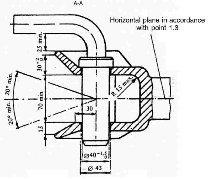

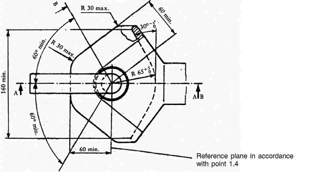
Figure 3
Example of tractor drawbar corresponding to ISO Standard 6489 Part 3 of June 2004

Figure 4
Ball type coupling (corresponding to ISO 24347:2005)
|
|
|
|
|
|


Figure 5
Pin type coupling (corresponding to ISO 6489-4:2004)
|
|
|
|
|
|
|
|
|


Table 2
|
Coupling component on the tractor |
Coupling component on the towed vehicle |
|
Corresponding to ISO 6489-1:2001 (hook type) |
Corresponding to ISO 5692-1:2004 (hitch ring, 50 mm hole centre, 30 mm ring diameter) or to ISO 20019:2001 (hitch ring, 50 mm hole centre, 30 to 41 mm ring diameter) or to ISO 5692-3:2011 (swivel hitch rings; compatible only with shape Y, 50 mm hole) |
|
Corresponding to ISO 6489-5:2011 (no swivel clevis coupling) |
Corresponding to ISO 5692-3:2011 (swivel hitch rings) |
|
Corresponding to ISO 6489-2:2002 (clevis type) |
Corresponding to ISO 5692-2:2002 (coupling ring, 40 mm socket) or to ISO 8755:2001 (40 mm drawbar eye) or to ISO 1102:2001 (50 mm drawbar eye, compatible only with ISO 6489-2:2002, shape A – non-automatic) |
|
Corresponding to ISO 6489-3:2004 (drawbar) |
Appropriate coupling type mentioned in this column that fits the drawbar dimensions of the tractor mentioned in this Appendix or corresponding to Sa vehicles’ hitch rings and attachment to tractor drawbars according to ISO 21244:2008. |
|
Corresponding to ISO 24347:2005 (ball type) |
Corresponding to ISO 24347:2005 (80 mm ball diameter) |
|
Corresponding to ISO 6489-4:2004 (piton type) |
Corresponding to ISO 5692-1:2004 (hitch ring, 50 mm hole centre, 30 mm ring diameter) or to ISO 5692-3:2011 (swivel hitch rings; compatible only with shape Y, 50 mm hole) |
Appendix 2
Mechanical Coupling Dynamic Test Method
1. Test procedure
The strength of the mechanical coupling shall be established by alternating traction on a test bed.
This method describes the fatigue test to be used on the complete mechanical coupling device, i.e. when fitted with all the parts needed for its installation the mechanical coupling is mounted and tested on a test bed.
The alternating forces shall be applied as far as possible sinusoidally (alternating and/or rising) with a load cycle depending on the material involved. No tears or breaks may occur during the test.
2. Test criteria
The horizontal force components in the longitudinal axis of the vehicle together with the vertical force components shall form the basis of the test loads.
In so far as they are of secondary importance, horizontal force components at right angles to the longitudinal axis of the vehicle and also moments shall not be taken into consideration.
The horizontal force components in the longitudinal axis of the vehicle shall be represented by a mathematically established representative force, the value D.
The following equation shall be applied to the mechanical coupling:

Where:
|
MT |
= |
the technically permissible maximum laden mass of the tractor, |
|
MR |
= |
the technically permissible maximum laden mass of the towed vehicles, |
|
g |
= |
9,81 m/s2. |
The vertical force components at right angles to the track shall be expressed by the static vertical load S.
The technically permissible loads shall be given by the manufacturer.
3. Test procedure requirements
3.1. General requirements
The test force shall be applied to the mechanical coupling device being tested by means of an appropriate standard drawbar ring beneath an angle formed by the position of the vertical test load Fv vis-à-vis the horizontal test load Fh in the direction of the median longitudinal plane passing from top front to bottom rear.
The test force shall be applied at the usual point of contact between the mechanical coupling device and the drawbar ring.
The play between the coupling device and the ring shall be kept to a minimum.
In principle the test force is applied in an alternating manner around the zero point. With an alternating test force the resulting load is equal to zero.
Should the design of the coupling device (e.g. excessive play, towing hook) make it impossible to carry out the test with an alternating test load, the test load may also be applied on a rising basis in the direction of traction or pressure, whichever is the greater.
Where the test is carried out with a rising force curve, the test load is equal to the upper (highest) load, and the lower (smallest) load should not exceed 5 % of the upper load.
Care should be taken in the alternating force test to ensure that by suitable mounting of the test apparatus and choice of power conduction system no additional moments or forces arising at right angles to the test force are introduced; the angular error for the direction of force in the alternating force test should not exceed ± 1,5°; and for the rising force test the angle is set in the upper load position.
The test frequency shall not exceed 30 Hz.
For components made of steel or steel casting the load cycle amounts to  . The subsequent tear test shall be carried out using the colour penetration method or similar method.
If springs and/or dampers are incorporated into the coupling parts, they shall not be removed during the test but may be replaced if, during the test, they are subject to strain under conditions which would not obtain during normal operation (e.g. heat action) and become damaged. Their behaviour before, during and after the test shall be described in the test report.
3.2. Test forces
The test force shall consist in geometrical terms of the horizontal and vertical test components as follows:
![]()
where:
Fh=  (kN) in the case of alternating force,
or
Fh=  (kN) in the case of rising force (traction or pressure),
Fv=  (value expressed in kN)
S= static drawbar load (load on the track, expressed in kg).
Appendix 3
Mechanical Coupling Static Test Method
1. Test specifications
1.1. General
|
1.1.1. |
Subject to a check on its construction characteristics, the mechanical coupling shall undergo static tests in accordance with the requirements of points 1.2, 1.3 and 1.4. |
1.2. Test preparation
The tests shall be carried out on a special machine, with the mechanical coupling and any structure coupling it to the body of the tractor attached to a rigid structure by means of the same components used to mount it on the tractor.
1.3. Test instruments
The instruments used to record loads applied and movements shall have the following degree of accuracy:
|
— |
loads applied ± 50 daN, |
|
— |
movements ± 0,01 mm. |
1.4. Test procedure
|
1.4.1. |
The coupling device shall first be subjected to a pre-traction load which does not exceed 15 % of the traction test load defined in point 1.4.2. |
|
1.4.1.1. |
The operation described in point 1.4.1 shall be repeated at least twice, starting with a zero load, which is gradually increased until the value prescribed in point 1.4.1 is reached, and then decreased to 500 daN; the settling load shall be maintained for at least 60 seconds. |
|
1.4.2. |
The data recorded for plotting the load/deformation curve under traction, or the graph of that curve provided by the printer linked to the traction machine, shall be based on the application of increasing loads only, starting from 500 daN, in relation to the reference centre of the coupling device. There shall be no breaks for values up to and including the traction test load which is established as 1,5 times the technically permissible trailer mass; in addition, the load/deformation curve shall show a smooth progression, without irregularities, in the interval between 500 daN and 1/3 of the maximum traction load. |
|
1.4.2.1. |
Permanent deformation is recorded on the load/deformation curve in relation to the load of 500 daN after the test load has been brought back to that value. |
|
1.4.2.2. |
The permanent deformation value recorded shall not exceed 25 % of the maximum elastic deformation occurring. |
1.5. The test referred to in point 1.4.2 shall be preceded by a test in which an initial load of three times the maximum permissible vertical force (in daN, equal to  ) recommended by the manufacturer is applied in a gradually increasing manner, starting from an initial load of 500 daN, to the reference centre of the coupling device.
During the test, deformation of the coupling device shall not exceed 10 % of the maximum elastic deformation occurring.
The check is carried out after removing the vertical force (in daN, equal to  ) and returning to the initial load of 500 daN.