

EUR-Lex Access to European Union law
This document is an excerpt from the EUR-Lex website
Document 02009R1222-20190726
Regulation (EC) No 1222/2009 of the European Parliament and of the Council of 25 November 2009 on the labelling of tyres with respect to fuel efficiency and other essential parameters (Text with EEA relevance)Text with EEA relevance
Consolidated text: Regulation (EC) No 1222/2009 of the European Parliament and of the Council of 25 November 2009 on the labelling of tyres with respect to fuel efficiency and other essential parameters (Text with EEA relevance)Text with EEA relevance
Regulation (EC) No 1222/2009 of the European Parliament and of the Council of 25 November 2009 on the labelling of tyres with respect to fuel efficiency and other essential parameters (Text with EEA relevance)Text with EEA relevance
 No longer in force
02009R1222 — EN — 26.07.2019 — 002.001
This text is meant purely as a documentation tool and has no legal effect. The Union's institutions do not assume any liability for its contents. The authentic versions of the relevant acts, including their preambles, are those published in the Official Journal of the European Union and available in EUR-Lex. Those official texts are directly accessible through the links embedded in this document
|
REGULATION (EC) No 1222/2009 OF THE EUROPEAN PARLIAMENT AND OF THE COUNCIL of 25 November 2009 on the labelling of tyres with respect to fuel efficiency and other essential parameters (OJ L 342 22.12.2009, p. 46) |
Amended by:
|
|
|
Official Journal |
||
|
No |
page |
date |
||
|
L 62 |
1 |
9.3.2011 |
||
|
L 317 |
17 |
30.11.2011 |
||
|
REGULATION (EU) 2019/1243 OF THE EUROPEAN PARLIAMENT AND OF THE COUNCIL of 20 June 2019 |
L 198 |
241 |
25.7.2019 |
|
REGULATION (EC) No 1222/2009 OF THE EUROPEAN PARLIAMENT AND OF THE COUNCIL
of 25 November 2009
on the labelling of tyres with respect to fuel efficiency and other essential parameters
(Text with EEA relevance)
Article 1
Aim and subject matter
1. The aim of this Regulation is to increase the safety, and the economic and environmental efficiency of road transport by promoting fuel-efficient and safe tyres with low noise levels.
2. This Regulation establishes a framework for the provision of harmonised information on tyre parameters through labelling, allowing end-users to make an informed choice when purchasing tyres.
Article 2
Scope
1. This Regulation shall apply to C1, C2 and C3 tyres.
2. This Regulation shall not apply to:
(a) re-treaded tyres;
(b) off-road professional tyres;
(c) tyres designed to be fitted only to vehicles registered for the first time before 1 October 1990;
(d) T-type temporary-use spare tyres;
(e) tyres whose speed rating is less than 80 km/h;
(f) tyres whose nominal rim diameter does not exceed 254 mm or is 635 mm or more;
(g) tyres fitted with additional devices to improve traction properties, such as studded tyres;
(h) tyres designed only to be fitted on vehicles intended exclusively for racing.
Article 3
Definitions
For the purpose of this Regulation:
1. ‘C1, C2 and C3 tyres’ means the tyre classes defined in Article 8 of Regulation (EC) No 661/2009;
2. ‘T-type temporary-use spare tyre’ means a temporary-use spare tyre designed for use at inflation pressures higher than those established for standard and reinforced tyres;
3. ‘point of sale’ means a location where tyres are displayed or stored and offered for sale to end-users, including car show rooms in relation to tyres offered for sale to end-users which are not fitted on the vehicles;
4. ‘technical promotional material’ means technical manuals, brochures, leaflets and catalogues (whether these appear in printed, electronic or online form), as well as websites, the purpose of which is to market tyres to end-users or distributors and that describe the specific technical parameters of a tyre;
5. ‘technical documentation’ means information relating to tyres, including the manufacturer and brand of the tyre; description of the tyre type or the grouping of tyres determined for the declaration of the fuel efficiency class, wet grip class and external rolling noise class and measured value; test reports and testing accuracy;
6. ‘manufacturer’ means any natural or legal person who manufactures a product, or has a product designed or manufactured and markets that product under his name or trademark;
7. ‘importer’ means any natural or legal person established within the Community who places a product from a third country on the Community market;
8. ‘authorised representative’ means any natural or legal person established within the Community who has received a written mandate from a manufacturer to act on his behalf in relation to specified tasks with regard to the latter's obligations under this Regulation;
9. ‘supplier’ means the manufacturer or its authorised representative in the Community or the importer;
10. ‘distributor’ means any natural or legal person in the supply chain, other than the supplier or the importer, who makes a tyre available on the market;
11. ‘making available on the market’ means any supply of a product for distribution or use on the Community market in the course of a commercial activity, whether in return for payment or free of charge;
12. ‘end-user’ means a consumer, as well as a fleet manager or road transport undertaking, that buys or is expected to buy a tyre;
13. ‘essential parameter’ means a tyre parameter such as rolling resistance, wet grip or external rolling noise that has a notable impact on the environment, road safety or health during use.
Article 4
Responsibilities of tyre suppliers
1. Suppliers shall ensure that C1 and C2 tyres, which are delivered to distributors or end-users, are:
(a) equipped with a sticker on the tyre tread displaying a label indicating the fuel efficiency class as set out in Annex I, Part A, the external rolling noise class and measured value as set out in Annex I, Part C and, where applicable, the wet grip class as set out in Annex I, Part B,
or
(b) for each batch of one or more identical tyres delivered, accompanied by a label in printed format indicating the fuel efficiency class as set out in Annex I, Part A, the external rolling noise class and measured value as set out in Annex I, Part C and, where applicable, the wet grip class as set out in Annex I, Part B.
2. The format of the sticker and the label referred to in paragraph 1 shall be as prescribed in Annex II.
3. Suppliers shall state the fuel efficiency class, the external rolling noise class and measured value and, where applicable, the wet grip class, of C1, C2 and C3 tyres in technical promotional material, including on their websites, as set out in Annex I, in the order specified in Annex III.
4. Suppliers shall make technical documentation available to the authorities of Member States on request, for a period ending five years after the last tyre of a given tyre type has been made available on the market. The technical documentation shall be sufficiently detailed as to allow the authorities to verify the accuracy of information provided on the label with regard to fuel efficiency, wet grip and external rolling noise.
Article 5
Responsibilities of tyre distributors
1. Distributors shall ensure that:
(a) tyres, at the point of sale, bear the sticker provided by suppliers in accordance with Article 4(1)(a) in a clearly visible position,
or
(b) before the sale of the tyre, the label referred to in Article 4(1)(b) is shown to the end-user and is clearly displayed in the immediate proximity of the tyre at the point of sale.
2. Where tyres offered for sale are not visible to the end-user, distributors shall provide end-users with information on the fuel efficiency class, wet grip class and external rolling noise class and measured value of those tyres.
3. For C1, C2 and C3 tyres, distributors shall state the fuel efficiency class, the external rolling noise measured value and, where applicable, the wet grip class, as set out in Annex I, on or with the bills delivered to end-users when they purchase tyres.
Article 6
Responsibilities of vehicle suppliers and vehicle distributors
Where end users are offered a choice at the point of sale between different tyres to be fitted on a new vehicle which they are intending to acquire, vehicle suppliers and distributors shall, before the sale, provide them with information, for each of the tyres offered, on the fuel efficiency class, the external rolling noise class and measured value, and, where applicable, the wet grip class of C1, C2 and C3 tyres, as set out in Annex I and in the order specified in Annex III. That information shall be included at least in the technical promotional material.
Article 7
Harmonised testing methods
The information to be provided under Articles 4, 5 and 6 on the fuel efficiency class, the external rolling noise class and measured value, and the wet grip class of tyres shall be obtained by applying the harmonised testing methods referred to in Annex I.
Article 8
Verification procedure
Member States shall assess the conformity of the declared fuel efficiency and wet grip classes, within the meaning of Annex I, Parts A and B, and the declared external rolling noise class and measured value within the meaning of Annex I, Part C, in accordance with the procedure set out in Annex IV.
Article 9
Internal market
1. Where the requirements of this Regulation are complied with, Member States shall neither prohibit nor restrict the making available on the market of the tyres referred to in Article 2 on grounds of product information.
2. Unless they have evidence to the contrary, Member States shall consider that labels and product information comply with this Regulation. They may require suppliers to provide technical documentation, in accordance with Article 4(4), in order to assess the accuracy of the declared values and classes.
Article 10
Incentives
Member States shall not provide incentives with regard to tyres below class C with respect to either fuel efficiency or wet grip within the meaning of Annex I, Parts A and B respectively. Taxation and fiscal measures do not constitute incentives for the purpose of this Regulation.
Article 11
Amendments and adaptations to technical progress
The Commission is empowered to adopt delegated acts in accordance with Article 12a amending this Regulation in respect of the following:
(a) introduction of information requirements with respect to wet grip grading of C2 and C3 tyres, provided that suitable harmonised testing methods are available;
(b) adaptation, where relevant, of grip grading to the technical specificities of tyres primarily designed to perform better in ice and/or snow conditions than a normal tyre with regard to their ability to initiate, maintain, or stop vehicle motion;
(c) adaptation of Annexes I to V to technical progress.
Article 12
Enforcement
In accordance with Regulation (EC) No 765/2008 Member States shall ensure that the authorities responsible for market surveillance verify compliance with Articles 4, 5 and 6 of this Regulation.
Article 12a
Exercise of the delegation
1. The power to adopt delegated acts is conferred on the Commission subject to the conditions laid down in this Article.
2. The power to adopt delegated acts referred to in Article 11 shall be conferred on the Commission for a period of five years from 26 July 2019. The Commission shall draw up a report in respect of the delegation of power not later than nine months before the end of the five-year period. The delegation of power shall be tacitly extended for periods of an identical duration, unless the European Parliament or the Council opposes such extension not later than three months before the end of each period.
3. The delegation of power referred to in Article 11 may be revoked at any time by the European Parliament or by the Council. A decision to revoke shall put an end to the delegation of the power specified in that decision. It shall take effect the day following the publication of the decision in the Official Journal of the European Union or at a later date specified therein. It shall not affect the validity of any delegated acts already in force.
4. Before adopting a delegated act, the Commission shall consult experts designated by each Member State in accordance with the principles laid down in the Interinstitutional Agreement of 13 April 2016 on Better Law-Making ( 1 ).
5. As soon as it adopts a delegated act, the Commission shall notify it simultaneously to the European Parliament and to the Council.
6. A delegated act adopted pursuant to Article 11 shall enter into force only if no objection has been expressed either by the European Parliament or by the Council within a period of two months of notification of that act to the European Parliament and the Council or if, before the expiry of that period, the European Parliament and the Council have both informed the Commission that they will not object. That period shall be extended by two months at the initiative of the European Parliament or of the Council.
▼M3 —————
Article 14
Review
1. The Commission shall assess the need to review this Regulation, taking into account, inter alia:
(a) the effectiveness of the label in terms of end-user awareness, in particular whether the provisions of Article 4(1)(b) are as effective as those of Article 4(1)(a) in contributing to the objectives of this Regulation;
(b) whether the labelling scheme should be extended to include retreaded tyres;
(c) whether new tyre parameters, such as mileage, should be introduced;
(d) the information on tyre parameters provided by vehicle suppliers and distributors to end-users.
2. The Commission shall present the result of this assessment to the European Parliament and the Council no later than 1 March 2016, and, if appropriate, submit proposals to the European Parliament and to the Council.
Article 15
Transitional provision
Articles 4 and 5 shall not apply to tyres produced before 1 July 2012.
Article 16
Entry into force
This Regulation shall enter into force on the 20th day following its publication in the Official Journal of the European Union.
This Regulation shall apply from 1 November 2012.
This Regulation shall be binding in its entirety and directly applicable in all Member States.
ANNEX I
GRADING OF TYRE PARAMETERS
Part A: Fuel efficiency classes
The fuel efficiency class must be determined on the basis of the rolling resistance coefficient (RRC) according to the ‘A’ to ‘G’ scale specified below and measured in accordance with Annex 6 of UNECE Regulation No 117 and its subsequent amendments and aligned according to the procedure laid down in Annex IVa.
If a tyre type is approved for more than one tyre class (e.g. C1 and C2), the grading scale used to determine the fuel efficiency class of this tyre type should be that which is applicable to the highest tyre class (e.g. C2, not C1).
|
C1 tyres |
C2 tyres |
C3 tyres |
|||
|
RRC in kg/t |
Energy efficiency class |
RRC in kg/t |
Energy efficiency class |
RRC in kg/t |
Energy efficiency class |
|
RRC ≤ 6,5 |
A |
RRC ≤ 5,5 |
A |
RRC ≤ 4,0 |
A |
|
6,6 ≤ RRC ≤ 7,7 |
B |
5,6 ≤ RRC ≤ 6,7 |
B |
4,1 ≤ RRC ≤ 5,0 |
B |
|
7,8 ≤ RRC ≤ 9,0 |
C |
6,8 ≤ RRC ≤ 8,0 |
C |
5,1 ≤ RRC ≤ 6,0 |
C |
|
Empty |
D |
Empty |
D |
6,1 ≤ RRC ≤ 7,0 |
D |
|
9,1 ≤ RRC ≤ 10,5 |
E |
8,1 ≤ RRC ≤ 9,2 |
E |
7,1 ≤ RRC ≤ 8,0 |
E |
|
10,6 ≤ RRC ≤ 12,0 |
F |
9,3 ≤ RRC ≤ 10,5 |
F |
RRC ≥ 8,1 |
F |
|
RRC ≥ 12,1 |
G |
RRC ≥ 10,6 |
G |
Empty |
G |
Part B: Wet grip classes
1. The wet grip class of C1 tyres must be determined on the basis of the wet grip index (G) according to the ‘A’ to ‘G’ scale specified in the table below, calculated in accordance with point 3 and measured in accordance with Annex V.
2. The wet grip class of C2 and C3 tyres must be determined on the basis of the wet grip index (G) according to the ‘A’ to ‘G’ scale specified in the table below, calculated in accordance with point (3) and measured in accordance with ISO 15222:2011 whereby the following Standard Reference Test Tyres (SRTT) must be used:
(i) for C2 tyres, the SRTT 225/75 R 16 C, ASTM F 2872-11;
(ii) for C3 tyres having Nominal Section Width lower than 285 mm, the SRTT 245/70R19.5, ASTM F 2871-11;
(iii) for C3 tyres having Nominal Section Width greater than or equal to 285 mm, the SRTT 315/70R22.5, ASTM F 2870-11.
3. Calculation of wet grip index (G)
G = G(T) – 0,03
where: G(T) = wet grip index of the candidate tyre as measured in one test cycle
|
C1 tyres |
C2 tyres |
C3 tyres |
|||
|
G |
Wet grip class |
G |
Wet grip class |
G |
Wet grip class |
|
1,55 ≤ G |
A |
1,40 ≤ G |
A |
1,25 ≤ G |
A |
|
1,40 ≤ G ≤ 1,54 |
B |
1,25 ≤ G ≤ 1,39 |
B |
1,10 ≤ G ≤ 1,24 |
B |
|
1,25 ≤ G ≤ 1,39 |
C |
1,10 ≤ G ≤ 1,24 |
C |
0,95 ≤ G ≤ 1,09 |
C |
|
Empty |
D |
Empty |
D |
0,80 ≤ G ≤ 0,94 |
D |
|
1,10 ≤ G ≤ 1,24 |
E |
0,95 ≤ G ≤ 1,09 |
E |
0,65 ≤ G ≤ 0,79 |
E |
|
G ≤ 1,09 |
F |
G ≤ 0,94 |
F |
G ≤ 0,64 |
F |
|
Empty |
G |
Empty |
G |
Empty |
G |
Part C: External rolling noise classes and measured value
The external rolling noise measured value (N) must be declared in decibels and calculated in accordance with UNECE Regulation No 117 and its subsequent amendments.
The external rolling noise class must be determined on the basis of the limit values (LV) set out in Part C of Annex II of Regulation (EC) No 661/2009 as follows.
|
N in dB |
External rolling noise class |
|
N ≤ LV – 3 |
|
|
LV – 3 < N ≤ LV |
|
|
N > LV |
|
ANNEX II
FORMAT OF THE LABEL
1. Label design
|
1.1. |
The label referred to in Articles 4(1) and 5(1) must be in accordance with the illustration below: 
|
|
1.2. |
The following provides specifications for the label: 
|
|
1.3. |
The label must be at least 75 mm wide and 110 mm high. Where the label is printed in a larger format, its content must nevertheless remain proportionate to the specifications above. |
|
1.4. |
The label must conform to the following requirements: (a) Colours are CMYK – cyan, magenta, yellow and black – and are given following this example: 00-70-X-00: 0 % cyan, 70 % magenta, 100 % yellow, 0 % black; (b) The numbers listed below refer to the legends indicated in point 1.2:
Pictogram as supplied: width: 19,5 mm, height: 18,5 mm – Frame for pictogram: stroke: 3,5 pt, width: 26 mm, height: 23 mm – Frame for grading: stroke: 1 pt – Frame end: stroke: 3,5 pt, width: 36 mm – Colour: X-10-00-05;
Pictogram as supplied: width: 19 mm, height: 19 mm – Frame for pictogram: stroke: 3,5 pt, width: 26 mm, height: 23 mm – Frame for grading: stroke: 1 pt – Frame end: stroke: 3,5 pt, width: 26 mm – Colour: X-10-00-05;
Pictogram as supplied: width: 14 mm, height: 15 mm – Frame for pictogram: stroke: 3,5 pt, width: 26 mm, height: 24 mm – Frame for value: stroke: 1 pt – Frame end: stroke: 3,5 pt, height: 24 mm – Colour: X-10-00-05;
Arrows: height: 4,75 mm, gap: 0,75 mm, black stroke: 0,5 pt – colours: — A: X-00-X-00; — B: 70-00-X-00; — C: 30-00-X-00 — D: 00-00-X-00; — E: 00-30-X-00 — F: 00-70-X-00; — G: 00-X-X-00. Text: Helvetica Bold 12 pt, 100 % white, black outline: 0,5 pt;
Arrow: width: 16 mm, height: 10 mm, 100 % black; Text: Helvetica Bold 27 pt, 100 % white;
Arrow: width: 25,25 mm, height: 10 mm, 100 % black; Text: Helvetica Bold 20 pt, 100 % white; Unit text: Helvetica Bold 13 pt, 100 % white;
Tyre class reference: Helvetica Bold 7,5 pt, 100 % black;
(c) The background must be white. |
|
1.5. |
The tyre class (C1 or C2) must be indicated on the label in the format prescribed in the illustration in point 1.2. |
2. Sticker
|
2.1. |
The sticker referred to in Articles 4(1) and 5(1) consists of two parts: (i) a label printed in the format described in point 1 of this Annex and (ii) a brand space printed in accordance with the specifications described in point 2.2 of this Annex. |
|
2.2. |
Brand space: Suppliers must add their trade name or trade mark, the tyre line, tyre dimension, load index, speed rating and other technical specifications on the sticker along with the label, in any colour, format and design, provided that this does not detract from or disrupt the message on the label defined in point 1 of this Annex. The total surface of the sticker shall not exceed 250 cm2 and the total height of the sticker shall not exceed 220 mm. |
ANNEX III
Information provided in technical promotional material
|
1. |
Information on tyres must be provided in the order specified as follows: (i) the fuel efficiency class (letter ‘A’ to ‘G’); (ii) the wet grip class (letter ‘A’ to ‘G’); (iii) the external rolling noise class and measured value (dB). |
|
2. |
The information provided in point 1 must meet the following requirements: (i) be easy to read; (ii) be easy to understand; (iii) if different grading is available for a given tyre type depending on dimension or other parameters, the range between the least and best performing tyre is stated. |
|
3. |
Suppliers must also make the following available on their websites: (i) a link to the relevant Commission webpage dedicated to this Regulation; (ii) an explanation of the pictograms printed on the label; (iii) a statement highlighting the fact that actual fuel savings and road safety depend heavily on the behaviour of drivers, and in particular the following: — eco-driving can significantly reduce fuel consumption, — tyre pressure should be regularly checked to optimise wet grip and fuel efficiency performance, — stopping distances should always be strictly respected, |
ANNEX IV
Verification procedure
The conformity of the declared fuel efficiency and wet grip classes, as well as the declared external rolling noise class and declared value, must be assessed for each tyre type or each grouping of tyres as determined by the supplier, according to one of the following procedures:
(a)
(i) a single tyre or tyre set is tested first. If the measured values meet the declared classes or external rolling noise declared value to within the tolerance defined in Table 1, the test is successfully passed; and
(ii) if the measured values do not meet the declared classes or external rolling noise declared value within the range defined in Table 1, three more tyres or tyre sets are tested. The average measurement value stemming from the three tyres or tyre sets tested is used to assess conformity with the declared information within the range defined in Table 1; or
(b) where the labelled classes or values are derived from type approval test results obtained in accordance with Directive 2001/43/EC, Regulation (EC) No 661/2009, or UNECE Regulation No 117 and its subsequent amendments, Member States may make use of measurement data obtained from conformity of production tests on tyres.
Assessment of the measurement data obtained from the conformity of production tests must take into account the allowances defined in Table 1.
Table 1
|
Measured parameter |
Verification tolerances |
|
Rolling resistance coefficient (fuel efficiency) |
The aligned measured value shall not be greater than the upper limit (the highest RRC) of the declared class by more than 0,3 kg/1 000 kg. |
|
External rolling noise |
The measured value shall not be greater than the declared value of N by more than 1 dB(A). |
|
Wet grip |
The measured value shall not be lower than the lower limit (the lowest value of G) of the declared class. |
ANNEX IVa
Laboratory alignment procedure for the measurement of rolling resistance
1. DEFINITIONS
For the purpose of the laboratory alignment procedure, the following definitions apply:
(1) ‘Reference laboratory’ means a laboratory that is part of the network of laboratories the references of which have been published for the purpose of the alignment procedure in the Official Journal of the European Union, and is able to achieve the accuracy of test results determined in section 3;
(2) ‘Candidate laboratory’ means a laboratory participating in the alignment procedure that is not a reference laboratory;
(3) ‘Alignment tyre’ means a tyre that is tested for the purpose of performing the alignment procedure;
(4) ‘Alignment tyres set’ means a set of five or more alignment tyres;
(5) ‘Assigned value’ means a theoretical value of one alignment tyre as measured by a theoretical laboratory which is representative of the network of reference laboratories that is used for the alignment procedure.
2. GENERAL PROVISIONS
2.1. Principle
The measured Rolling Resistance Coefficient (RRCm ) in a reference laboratory (l) shall be aligned to the assigned values of the network of reference laboratories.
The RRCm in a candidate laboratory (c) shall be aligned through one reference laboratory of the network of its choice.
2.2. Tyre selection requirements
A set of five or more alignment tyres shall be selected for the alignment procedure in compliance with the criteria below. One set shall be selected for C1 and C2 tyres together, and one set for C3 tyres.
(a) The set of alignment tyres shall be selected so as to cover the range of different RRCs of C1 and C2 tyres together, or of C3 tyres. In any event, the difference between the highest RRCm of the tyre set, and the lowest RRCm of the tyre set shall be at least equal to:
(i) 3 kg/t for C1 and C2 tyres; and
(ii) 2 kg/t for C3 tyres.
(b) The RRCm in the candidate or reference laboratories (c or l) based on declared RRC values of each alignment tyre of the set shall be spaced out as follows and distributed uniformly:
(i) 1,0 +/– 0,5 kg/t for C1 and C2 tyres; and
(ii) 1,0 +/– 0,5 kg/t for C3 tyres.
(c) The selected tyre section width of each alignment tyre shall be:
(i) ≤ 245 mm for machines measuring C1 and C2 tyres; and
(ii) ≤ 385 mm for machines measuring C3 tyres.
(d) The selected tyre outer diameter of each alignment tyre shall be:
(i) between 510 to 800 mm for machines measuring C1 and C2 tyres; and
(ii) between 771 to 1 143 mm for machines measuring C3 tyres.
(e) Load index values shall adequately cover the range of the tyres to be tested, ensuring that the rolling resistance force (RRF) values also cover the range of the tyres to be tested.
Each alignment tyre shall be checked prior to use and replaced when:
(a) it shows a condition which makes it unusable for further tests; and/or
(b) there are deviations of RRCm greater than 1,5 per cent relative to earlier measurements after correction for any machine drift.
2.3. Measurement method
The reference laboratory shall measure each alignment tyre four times and retain the three last results for further analysis, in accordance with paragraph 4 of Annex 6 of UNECE Regulation No 117 and its subsequent amendments and applying the conditions set out in paragraph 3 of Annex 6 of UNECE Regulation No 117 and its subsequent amendments.
The candidate laboratory shall measure each alignment tyre (n + 1) times with n being specified in section 5 and retain the n last results for further analysis, in accordance with paragraph 4 of Annex 6 of UNECE Regulation No 117 and its subsequent amendments and applying the conditions set out in paragraph 3 of Annex 6 of UNECE Regulation No 117 and its subsequent amendments.
Each time an alignment tyre is measured, the tyre/wheel assembly shall be removed from the machine and the entire test procedure specified in paragraph 4 of Annex 6 of UNECE Regulation No 117 and its subsequent amendments shall be followed again from the start.
The candidate or reference laboratory shall calculate:
(a) the measured value of each alignment tyre for each measurement as specified in Annex 6, paragraphs 6.2 and 6.3, of UNECE Regulation No 117 and its subsequent amendments (i.e. corrected for a temperature of 25 °C and a drum diameter of 2 m);
(b) the mean value of the three (in the case of reference laboratories) or n (in the case of candidate laboratories) last measured values of each alignment tyre; and
(c) the standard deviation (σm) as follows:

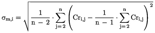
where:
|
i |
is the counter from 1 to p for the number of alignment tyres |
|
j |
is the counter from 2 to n for the number of repetitions of each measurement for a given alignment tyre |
|
n |
is the number of repetitions of tyre measurements (n ≥4) |
|
p |
is the number of alignment tyres (p ≥ 5) |
2.4. Data formats to be used for the computations and results
— The measured RRC values corrected from drum diameter and temperature shall be rounded to 2 decimal places.
— Then the computations shall be made with all digits: there shall be no further rounding except on the final alignment equations.
— All standard deviation values shall be displayed to 3 decimal places.
— All RRC values will be displayed to 2 decimal places.
— All alignment coefficients (A1l, B1l, A2c and B2c) shall be rounded and displayed to 4 decimal places.
3. REQUIREMENTS APPLICABLE TO THE REFERENCE LABORATORIES AND DETERMINATION OF THE ASSIGNED VALUES
The assigned values of each alignment tyre shall be determined by a network of reference laboratories. After two years the network shall assess the stability and validity of the assigned values.
Each reference laboratory participating in the network shall comply with the specifications of Annex 6 of UNECE Regulation No 117 and its subsequent amendments and have a standard deviation (σm) as follows:
(i) not greater than 0,05 kg/t for class C1 and C2 tyres; and
(ii) not greater than 0,05 kg/t for class C3 tyres.
The sets of alignment tyres, conforming to the specification of section 2.2 shall be measured in accordance with section 2.3 by each reference laboratory of the network.
The assigned value of each alignment tyre is the average of the measured values given by the reference laboratories of the network for this alignment tyre.
4. PROCEDURE FOR THE ALIGNMENT OF A REFERENCE LABORATORY TO THE ASSIGNED VALUES
Each reference laboratory (l) shall align itself to the assigned values of the alignment tyre set using a linear regression technique, A1 l and B1 l , calculated as follows:
RRC = A1 l * RRC m,l + B1 l
where:
|
RRC |
is the assigned value of the rolling resistance coefficient; |
|
RRCm, |
is the measured value of the rolling resistance coefficient by the reference laboratory ‘l’ (including temperature and drum diameter corrections) |
5. REQUIREMENTS APPLICABLE TO CANDIDATE LABORATORIES
Candidate laboratories shall repeat the alignment procedure at least once every two years and always after any significant machine change or any drift in machine control tyre monitoring data.
A common set of five different tyres, conforming to the specification of section 2.2 shall be measured in accordance with section 2.3 by the candidate laboratory and by one reference laboratory. More than five alignment tyres may be tested at the request of the candidate laboratory.
The alignment tyre set shall be provided by the candidate laboratory to the selected reference laboratory.
The candidate laboratory (c) shall comply with the specifications of Annex 6 of UNECE Regulation No 117 and its subsequent amendments and preferably have standard deviations (σm ) as follows:
(i) not greater than 0,075 kg/t for C1 and C2 tyres; and
(ii) not greater than 0,06 kg/t for C3 tyres.
If the standard deviations (σm) of the candidate laboratory are higher than the above values with three measurements, then the number of measurement repetitions shall be increased as follows:
n = (σm /γ)2, rounded up to the nearest higher integer value
where:
|
γ |
= |
0,043 kg/t for Class C1 and C2 tyres |
|
γ |
= |
0,035 kg/t for Class C3 tyres |
6. PROCEDURE FOR THE ALIGNMENT OF A CANDIDATE LABORATORY
One reference laboratory (l) of the network shall calculate the linear regression function of the candidate laboratory (c), A2c and B2c, as follows:
RRC m,l = A2c × RRCm,c + B2c
where:
|
RRCm,l |
is the measured value of the rolling resistance coefficient by the reference laboratory (l) (including temperature and drum diameter corrections) |
|
RRCm,c |
is the measured value of the rolling resistance coefficient by the candidate laboratory (c) (including temperature and drum diameter corrections) |
The aligned RRC of tyres tested by the candidate laboratory is calculated as follows:
RRC = (A1 l × A2c) × RRCm,c + (A1 l × B2c + B1 l )
ANNEX V
Testing method for measuring the wet grip index (G) of C1 tyres
1. MANDATORY STANDARDS
The following documents listed apply.
(1) ASTM E 303-93 (Reapproved 2008), Standard Test Method for Measuring Surface Frictional Properties Using the British Pendulum Tester;
(2) ASTM E 501-08, Standard Specification for Standard Rib Tire for Pavement Skid-Resistance Tests;
(3) ASTM E 965-96 (Reapproved 2006), Standard Test Method for Measuring Pavement Macrotexture Depth Using a Volumetric Technique;
(4) ASTM E 1136-93 (Reapproved 2003), Standard Specification for a Radial Standard Reference Test Tire (SRTT14″);
(5) ASTM F 2493-08, Standard Specification for a Radial Standard Reference Test Tire (SRTT16″).
2. DEFINITIONS
For the purposes of testing wet grip of C1 tyres, the following definitions apply:
(1) ‘test run’ means a single pass of a loaded tyre over a given test track surface;
(2) ‘test tyre(s)’ means a candidate tyre, a reference tyre or a control tyre or tyre set that is used in a test run;
(3) ‘candidate tyre(s) (T)’ means a tyre or a tyre set that is tested for the purpose of calculating its wet grip index;
(4) ‘reference tyre(s) (R)’ means a tyre or a tyre set that has the characteristics indicated in ASTM F 2493-08 and referred to as Standard Reference Test Tyre 16 inches (SRTT16″);
(5) ‘control tyre(s) (C)’ means an intermediate tyre or a set of intermediate tyres which is used when the candidate tyre and the reference tyre cannot be directly compared on the same vehicle;
(6) ‘braking force of a tyre’ means the longitudinal force, expressed in newton, resulting from braking torque application;
(7) ‘braking force coefficient of a tyre (BFC)’ means the ratio of the braking force to the vertical load;
(8) ‘peak braking force coefficient of a tyre’ means the maximum value of a tyre braking force coefficient that occurs prior to wheel lockup as the braking torque is progressively increased;
(9) ‘lockup of a wheel’ means the condition of a wheel in which its rotational velocity about the wheel spin axis is zero and it is prevented from rotating in the presence of applied wheel torque;
(10) ‘vertical load’ means the load in newton imposed on the tyre perpendicular to the road surface;
(11) ‘tyre test vehicle’ means a dedicated special purpose vehicle which has instruments to measure the vertical and the longitudinal forces on one test tyre during braking.
3. GENERAL TEST CONDITIONS
3.1 Track characteristics
The test track shall have the following characteristics:
(1) The surface shall have a dense asphalt surface with a uniform gradient of not more than 2 % and shall not deviate more than 6 mm when tested with a 3 m straight edge.
(2) The surface shall have a pavement of uniform age, composition, and wear. The test surface shall be free of loose material and foreign deposits.
(3) The maximum chipping size shall be 10 mm (tolerances permitted from 8 mm to 13 mm).
(4) The texture depth as measured by a sand patch shall be 0,7 ± 0,3 mm. It shall be measured in accordance with ASTM E 965-96 (Reapproved 2006).
(5) The wetted frictional properties of the surface shall be measured with either method (a) or (b) in section 3.2.
3.2 Methods to measure the wetted frictional properties of the surface
(a) British Pendulum Number (BPN) method
The British Pendulum Number method shall be as defined in ASTM E 303-93 (Reapproved in 2008).
Pad rubber component formulation and physical properties shall be as specified in ASTM E 501-08.
The averaged British Pendulum Number (BPN) shall be between 42 and 60 BPN after temperature correction as follows.
BPN shall be corrected by the wetted road surface temperature. Unless temperature correction recommendations are indicated by the British pendulum manufacturer, the following formula is used:
BPN = BPN (measured value) + temperature correction
temperature correction = – 0,0018 t 2 + 0,34 t – 6,1
where t is the wetted road surface temperature in degrees Celsius.
Effects of slider pad wear: The pad shall be removed for maximum wear when the wear on the striking edge of the slider reaches 3,2 mm in the plane of the slider or 1,6 mm vertical to it in accordance with section 5.2.2 and Figure 3 of ASTM E 303-93 (Reapproved 2008).
For the purpose of checking track surface BPN consistency for the measurement of wet grip on an instrumented passenger car: the BPN values of the test track should not vary over the entire stopping distance so as to decrease the dispersion of test results. The wetted frictional properties of the surface shall be measured five times at each point of the BPN measurement every 10 meters and the coefficient of variation of the averaged BPN shall not exceed 10 %.
(b) ASTM E 1136 Standard Reference Test Tyre (SRTT14″) method
By derogation with point (4) of section 2, this method uses the reference tyre that has the characteristics indicated in ASTM E 1136-93 (Reapproved 2003) and referred to as SRTT14″ ( 2 ).
The average peak braking force coefficient (μpeak,ave ) of the SRTT14″ shall be 0,7 ± 0,1 at 65 km/h.
The average peak braking force coefficient (μpeak,ave ) of the SRTT14″ shall be corrected by the wetted road surface temperature as follows:
peak braking force coefficient (μpeak,ave ) = peak braking force coefficient (measured) + temperature correction
temperature correction = 0,0035 × (t – 20)
where t is the wetted road surface temperature in degrees Celsius.
3.3 Atmospheric conditions
The wind conditions shall not interfere with wetting of the surface (wind-shields are allowed).
Both the wetted surface temperature and the ambient temperature shall be between 2 °C and 20 °C for snow tyres and 5 °C and 35 °C for normal tyres.
The wetted surface temperature shall not vary during the test by more than 10 °C.
The ambient temperature must remain close to the wetted surface temperature; the difference between the ambient and the wetted surface temperatures must be less than 10 °C.
4. TESTING METHODS FOR MEASURING WET GRIP
For the calculation of the wet grip index (G) of a candidate tyre, the wet grip braking performance of the candidate tyre is compared to the wet grip braking performance of the reference tyre on a vehicle travelling straight ahead on a wet, paved surface. It is measured with one of the following methods:
— vehicle method consisting of testing a set of tyres mounted on an instrumented passenger car,
— testing method using a trailer towed by a vehicle or a tyre test vehicle, equipped with the test tyre(s).
4.1 Testing method using an instrumented passenger car
4.1.1 Principle
The testing method covers a procedure for measuring the deceleration performance of C1 tyres during braking, using an instrumented passenger car equipped with an Antilock Braking System (ABS), where ‘instrumented passenger car’ means a passenger car that is fitted with the measuring equipment listed in section 4.1.2.2 for the purpose of this testing method. Starting with a defined initial speed, the brakes are applied hard enough on four wheels at the same time to activate the ABS. The average deceleration is calculated between two pre-defined speeds.
4.1.2 Equipment
4.1.2.1
Permitted modifications on the passenger car are as follows:
— those allowing the number of tyre sizes that can be mounted on the vehicle to be increased,
— those permitting automatic activation of the braking device to be installed.
Any other modification of the braking system is prohibited.
4.1.2.2
The vehicle shall be fitted with a sensor suitable for measuring speed on a wet surface and distance covered between two speeds.
To measure vehicle speed, a fifth wheel or non-contact speed-measuring system shall be used.
4.1.3 Conditioning of the test track and wetting condition
The test track surface shall be watered at least half an hour prior to testing in order to equalise the surface temperature and water temperature. External watering should be supplied continuously throughout testing. For the whole testing area, the water depth shall be 1,0 ± 0,5 mm, measured from the peak of the pavement.
The test track should then be conditioned by conducting at least 10 test runs with tyres not involved in the test programme at 90 km/h.
4.1.4 Tyres and rims
4.1.4.1
The test tyres shall be trimmed to remove all protuberances on the tread surface caused by mould air vents or flashes at mould junctions.
The test tyres shall be mounted on the test rim declared by the tyre manufacturer.
A proper bead seat should be achieved by the use of a suitable lubricant. Excessive use of lubricant should be avoided to prevent slipping of the tyre on the wheel rim.
The test tyres/rim assemblies shall be stored in a location for a minimum of two hours such that they all have the same ambient temperature prior to testing. They should be shielded from the sun to avoid excessive heating by solar radiation.
For tyre break-in, two braking runs shall be performed.
4.1.4.2
The static load on each axle tyre shall lie between 60 % and 90 % of the tested tyre load capacity. Tyre loads on the same axle should not differ by more than 10 %.
4.1.4.3
On the front and rear axles, the inflation pressures shall be 220 kPa (for standard- and extra-load tyres). The tyre pressure should be checked just prior to testing at ambient temperature and adjusted if required.
4.1.5 Procedure
4.1.5.1
The following test procedure applies for each test run:
(1) The passenger car is driven in a straight line up to 85 ± 2 km/h.
(2) Once the passenger car has reached 85 ± 2 km/h, the brakes are always activated at the same place on the test track referred to as ‘braking starting point’, with a longitudinal tolerance of 5 m and a transverse tolerance of 0,5 m.
(3) The brakes are activated either automatically or manually.
(i) The automatic activation of the brakes is performed by means of a detection system made of two parts, one indexed to the test track and one on board the passenger car.
(ii) The manual activation of the brakes depends on the type of transmission as follows. In both cases, a minimum of 600 N pedal efforts is required.
For manual transmission, the driver should release the clutch and depress the brake pedal sharply, holding it down as long as necessary to perform the measurement.
For automatic transmission, the driver should select neutral gear and then depress the brake pedal sharply, holding it down as long as necessary to perform the measurement.
(4) The average deceleration is calculated between 80 km/h and 20 km/h.
If any of the specifications listed above (including speed tolerance, longitudinal and transverse tolerance for the braking starting point, and braking time) are not met when a test run is made, the measurement is discarded and a new test run is made.
4.1.5.2
A number of test runs are made in order to measure the wet grip index of a set of candidate tyres (T) according to the following procedure, whereby each test run shall be made in the same direction and up to three different sets of candidate tyres may be measured within the same test cycle:
(1) First, the set of reference tyres are mounted on the instrumented passenger car.
(2) After at least three valid measurements have been made in accordance with section 4.1.5.1, the set of reference tyres is replaced by a set of candidate tyres.
(3) After six valid measurements of the candidate tyres are performed, two more sets of candidate tyres may be measured.
(4) The test cycle is closed by three more valid measurements of the same set of reference tyres as at the beginning of the test cycle.
— The run order for a test cycle of three sets of candidate tyres (T1 to T3) plus a set of reference tyres (R) would be the following:
— R-T1-T2-T3-R
— The run order for a test cycle of five sets of candidate tyres (T1 to T5) plus a set of reference tyres (R) would be the following:
— R-T1-T2-T3-R-T4-T5-R
4.1.6 Processing of measurement results
4.1.6.1
The average deceleration (AD) is calculated for each valid test run in m·s– 2 as follows:

where:
Sf is the final speed in m·s– 1; Sf = 20 km/h = 5,556 m·s– 1
Si is the initial speed in m·s– 1; Si = 80 km/h = 22,222 m·s– 1
d is the distance covered in m between Si and Sf .
4.1.6.2
The AD coefficient of variation is calculated as follows:
(Standard Deviation / Average) × 100
For the reference tyres (R) : If the AD coefficient of variation of any two consecutive groups of three test runs of the reference tyre set is higher than 3 %, all data should be discarded and the test repeated for all test tyres (the candidate tyres and the reference tyres).
For the candidate tyres (T) : The AD coefficients of variation are calculated for each candidate tyre set. If one coefficient of variation is higher than 3 %, the data should be discarded and the test repeated for that candidate tyre set.
4.1.6.3
The average deceleration (AD) of the reference tyre set used for the calculation of its braking force coefficient is adjusted according to the positioning of each candidate tyre set in a given test cycle.
This adjusted AD of the reference tyre (Ra) is calculated in m·s–2 in accordance with table 1 where R1 is the average of the AD values in the first test of the reference tyre set (R) and R2 is the average of the AD values in the second test of the same reference tyre set (R).
Table 1
|
Number of sets of candidate tyres within one test cycle |
Set of candidate tyres |
Ra |
|
1 (R1 -T1-R2 ) |
T1 |
Ra = 1/2 (R1 + R2 ) |
|
2 (R1 -T1-T2-R2 ) |
T1 |
Ra = 2/3 R1 + 1/3 R2 |
|
T2 |
Ra = 1/3 R1 + 2/3 R2 |
|
|
3 (R1 -T1-T2-T3-R2 ) |
T1 |
Ra = 3/4 R1 + 1/4 R2 |
|
T2 |
Ra = 1/2 (R 1 + R2 ) |
|
|
T3 |
Ra = 1/4 R1 + 3/4 R2 |
4.1.6.4 (BFC)
The braking force coefficient (BFC) is calculated for a braking on the two axles according to Table 2 where Ta (a = 1, 2 or 3) is the average of the AD values for each candidate tyre (T) set that is part of a test cycle.
Table 2
|
Test Tyre |
Braking force coefficient |
|
Reference tyre |
BFC(R) = |Ra/g| |
|
Candidate tyre |
BFC(T) = |Ta/g| |
|
g is the acceleration due to gravity, g = 9,81 m·s-2 |
|
4.1.6.5
The wet grip index of the candidate tyre (G(T)) is calculated as follows:

where:
— t is the measured wet surface temperature in degree Celsius when the candidate tyre (T) is tested
— t0 is the wet surface reference temperature condition, t0 = 20 °C for normal tyres and t0 = 10 °C for snow tyres
— BFC(R0) is the braking force coefficient for the reference tyre in the reference conditions, BFC(R0) = 0,68
— a = – 0,4232 and b = – 8,297 for normal tyres, a = 0,7721 and b = 31,18 for snow tyres
4.1.7 Wet grip performance comparison between a candidate tyre and a reference tyre using a control tyre
4.1.7.1
Where the candidate tyre size is significantly different from that of the reference tyre, a direct comparison on the same instrumented passenger car may not be possible. This testing method uses an intermediate tyre, hereinafter called the control tyre as defined in point 5 of section 2.
4.1.7.2
The principle is the use of a control tyre set and two different instrumented passenger cars for the test cycle of a candidate tyre set in comparison with a reference tyre set.
One instrumented passenger car is fitted with the reference tyre set followed by the control tyre set, the other with the control tyre set followed by the candidate tyre set.
The specifications listed in sections 4.1.2 to 4.1.4 apply.
The first test cycle is a comparison between the control tyre set and the reference tyre set.
The second test cycle is a comparison between the candidate tyre set and the control tyre set. It is done on the same test track and during the same day as the first test cycle. The wetted surface temperature shall be within ± 5 °C of the temperature of the first test cycle. The same control tyre set shall be used for the first and the second test cycles.
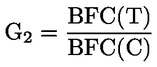
The wet grip index of the candidate tyre (G(T)) is calculated as follows:
G(T) = G1 × G2
where:
— G1 is the relative wet grip index of the control tyre (C) compared to the reference tyre (R) calculated as follows:
—

— G2 is the relative wet grip index of the candidate tyre (T) compared to the control tyre (C) calculated as follows:
—
4.1.7.3
It is necessary that all the tyres of a control tyre set have been stored in the same conditions. As soon as the control tyre set has been tested in comparison with the reference tyre, the specific storage conditions defined in ASTM E 1136-93 (Reapproved 2003) shall be applied.
4.1.7.4
When irregular wear or damage results from tests, or when wear influences the test results, the use of the tyre shall be discontinued.
4.2 Testing method using a trailer towed by a vehicle or a tyre test vehicle
4.2.1 Principle
The measurements are conducted on test tyres mounted on a trailer towed by a vehicle (hereafter referred to as tow vehicle) or on a tyre test vehicle. The brake in the test position is applied firmly until sufficient braking torque is generated to produce the maximum braking force that will occur prior to wheel lockup at a test speed of 65 km/h.
4.2.2 Equipment
4.2.2.1
— The tow vehicle or the tyre test vehicle shall have the capability of maintaining the specified speed of 65 ± 2 km/h even under the maximum braking forces.
— The trailer or the tyre test vehicle shall be equipped with one place where the tyre can be fitted for measurement purposes hereafter called ‘test position’ and the following accessories:
—
(i) equipment to activate brakes in the test position;
(ii) a water tank to store sufficient water to supply the road surface wetting system, unless external watering is used;
(iii) recording equipment to record signals from transducers installed at the test position and to monitor water application rate if the self-watering option is used.
— The maximum variation of toe-settings and camber angle for the test position shall be within ± 0,5 ° with maximum vertical load. Suspension arms and bushings shall have sufficient rigidity necessary to minimise free play and ensure compliance under application of maximum braking forces. The suspension system shall provide adequate load-carrying capacity and be of such a design as to isolate suspension resonance.
— The test position shall be equipped with a typical or special automotive brake system which can apply sufficient braking torque to produce the maximum value of braking test wheel longitudinal force at the conditions specified.
— The brake application system shall be able to control the time interval between initial brake application and peak longitudinal force as specified in section 4.2.7.1.
— The trailer or the tyre test vehicle shall be designed to accommodate the range of candidate tyre sizes to be tested.
— The trailer or the tyre test vehicle shall have provisions for adjustment of vertical load as specified in section 4.2.5.2.
4.2.2.2
— The test wheel position on the trailer or the tyre test vehicle shall be equipped with a rotational wheel velocity measuring system and with transducers to measure the braking force and vertical load at the test wheel.
— General requirements for measurement system: The instrumentation system shall conform to the following overall requirements at ambient temperatures between 0 °C and 45 °C:
—
(i) overall system accuracy, force: ± 1,5 % of the full scale of the vertical load or braking force;
(ii) overall system accuracy, speed: ± 1,5 % of speed or ± 1,0 km/h, whichever is greater.
— Vehicle speed: To measure vehicle speed, a fifth wheel or non-contact precision speed-measuring system should be used.
— Braking forces: The braking force-measuring transducers shall measure longitudinal force generated at the tyre–road interface as a result of brake application within a range from 0 % to at least 125 % of the applied vertical load. The transducer design and location shall minimise inertial effects and vibration-induced mechanical resonance.
— Vertical load: The vertical load-measuring transducer shall measure the vertical load at the test position during brake application. The transducer shall have the same specifications as described previously.
— Signal conditioning and recording system: All signal conditioning and recording equipment shall provide linear output with necessary gain and data reading resolution to meet the specified previous requirements. In addition, the following requirements apply:
—
(i) The minimum frequency response shall be flat from 0 Hz to 50 Hz (100 Hz) within ± 1 % full scale.
(ii) The signal-to-noise ratio shall be at least 20/1.
(iii) The gain shall be sufficient to permit full-scale display for full-scale input signal level.
(iv) The input impedance shall be at least 10 times larger than the output impedance of the signal source.
(v) The equipment shall be insensitive to vibrations, acceleration, and changes in ambient temperature.
4.2.3 Conditioning of the test track
The test track should be conditioned by conducting at least ten test runs with tyres not involved in the test program at 65 ± 2 km/h.
4.2.4 Wetting conditions
The tow vehicle and trailer or the tyre test vehicle may be optionally equipped with a pavement-wetting system, less the storage tank, which, in the case of the trailer, is mounted on the tow vehicle. The water being applied to the pavement ahead of the test tyres shall be supplied by a nozzle suitably designed to ensure that the water layer encountered by the test tyre has a uniform cross section at the test speed with a minimum splash and overspray.
The nozzle configuration and position shall ensure that the water jets are directed towards the test tyre and pointed towards the pavement at an angle of 20° to 30°.
The water shall strike the pavement 0,25 m to 0,45 m ahead of the centre of tyre contact. The nozzle shall be located 25 mm above the pavement or at the minimum height required to clear obstacles which the tester is expected to encounter, but in no case more than 100 mm above the pavement.
The water layer shall be at least 25 mm wider than the test tyre tread and applied so the tyre is centrally located between the edges. Water delivery rate shall ensure a water depth of 1,0 ± 0,5 mm and shall be consistent throughout the test to within ± 10 per cent. The volume of water per unit of wetted width shall be directly proportional to the test speed. The quantity of water applied at 65 km/h shall be 18 l·s-1 per meter of width of wetted surface in case of a water depth of 1,0 mm.
4.2.5 Tyres and rims
4.2.5.1
The test tyres shall be trimmed to remove all protuberances on the tread surface caused by mould air vents or flashes at mould junctions.
The test tyre shall be mounted on the test rim declared by the tyre manufacturer.
A proper bead seat should be achieved by the use of a suitable lubricant. Excessive use of lubricant should be avoided to prevent slipping of the tyre on the wheel rim.
The test tyres/rim assemblies shall be stored in a location for a minimum of two hours such that they all have the same ambient temperature prior to testing. They should be shielded from the sun to avoid excessive heating by solar radiation.
For tyre break-in, two braking runs shall be performed under the load, pressure and speed as specified in 4.2.5.2, 4.2.5.3 and 4.2.7.1 respectively.
4.2.5.2
The test load on the test tyre is 75 ± 5 % of the test tyre load capacity.
4.2.5.3
The test tyre cold inflation pressure shall be 180 kPa for standard-load tyres. For extra-load tyres, the cold inflation pressure shall be 220 kPa.
The tyre pressure should be checked just prior to testing at ambient temperature and adjusted if required.
4.2.6 Preparation of the tow vehicle and trailer or the tyre test vehicle
4.2.6.1
For one axle trailers, the hitch height and transverse position shall be adjusted once the test tyre has been loaded to the specified test load in order to avoid any disturbance of the measuring results. The longitudinal distance from the centre line of the articulation point of the coupling to the transverse centre line of the axle of the trailer shall be at least 10 times the ‘hitch height’ or the ‘coupling (hitch) height’.
4.2.6.2
Install the fifth wheel, when used, in accordance with the manufacturer’s specifications and locate it as near as possible to the mid-track position of the tow trailer or the tyre test vehicle.
4.2.7 Procedure
4.2.7.1
The following procedure applies for each test run:
(1) The tow vehicle or the tyre test vehicle is driven onto the test track in a straight line at the specified test speed 65 ± 2 km/h.
(2) The recording system is launched.
(3) Water is delivered to the pavement ahead of the test tyre approximately 0,5 s prior to brake application (for internal watering system).
(4) The trailer brakes are activated within 2 metres of a measurement point of the wetted frictional properties of the surface and sand depth in accordance with points 4 and 5 of section 3.1. The rate of braking application shall be such that the time interval between initial application of force and peak longitudinal force is in the range 0,2 s to 0,5 s.
(5) The recording system is stopped.
4.2.7.2
A number of test runs are made in order to measure the wet grip index of the candidate tyre (T) according to the following procedure, whereby each test run shall be made at the same spot on the test track and in the same direction. Up to three candidate tyres may be measured within the same test cycle, provided that the tests are completed within one day.
(1) First, the reference tyre is tested.
(2) After at least six valid measurements are performed in accordance with section 4.2.7.1, the reference tyre is replaced by the candidate tyre.
(3) After six valid measurements of the candidate tyre are performed, two more candidate tyres may be measured.
(4) The test cycle is closed by six more valid measurements of the same reference tyre as at the beginning of the test cycle.
— The run order for a test cycle of three candidate tyres (T1 to T3) plus the reference tyre (R) would be the following:
— R-T1-T2-T3-R
— The run order for a test cycle of five candidate tyres (T1 to T5) plus the reference tyre R would be the following:
— R-T1-T2-T3-R-T4-T5-R
4.2.8 Processing of measurement results
4.2.8.1
The tyre peak braking force coefficient (μpeak) is the highest value of μ(t) before lockup occurs calculated as follows for each test run. Analogue signals should be filtered to remove noise. Digitally recorded signals must be filtered using a moving average technique.

where:
μ(t) is the dynamic tyre braking force coefficient in real time;
fh(t) is the dynamic braking force in real time, in N;
fv(t) is the dynamic vertical load in real time, in N.
4.2.8.2
The μpeak coefficient of variation is calculated as follows:
(Standard Deviation / Average) x 100
For the reference tyre (R) : If the coefficient of variation of the peak braking force coefficient (μpeak) of the reference tyre is higher than 5 %, all data should be discarded and the test repeated for all test tyres (the candidate tyre(s) and the reference tyre).
For the candidate tyre(s) (T) : The coefficient of variation of the peak braking force coefficient (μpeak) is calculated for each candidate tyre. If one coefficient of variation is higher than 5 %, the data should be discarded and the test repeated for this candidate tyre.
4.2.8.3
The average peak braking force coefficient of the reference tyre used for the calculation of its braking force coefficient is adjusted according to the positioning of each candidate tyre in a given test cycle.
This adjusted average peak braking force coefficient of the reference tyre (Ra) is calculated in accordance with table 3 where R1 is the average peak tyre braking coefficient in the first test of the reference tyre (R) and R2 is the average peak tyre braking coefficient in the second test of the same reference tyre (R).
Table 3
|
Number of candidate tyre(s) within one test cycle |
Candidate tyre |
Ra |
|
1 (R1 -T1-R2 ) |
T1 |
Ra = 1/2 (R1 + R2 ) |
|
2 (R1 -T1-T2-R2 ) |
T1 |
Ra = 2/3 R1 + 1/3 R2 |
|
T2 |
Ra = 1/3 R1 + 2/3 R2 |
|
|
3 (R1 -T1-T2-T3-R2 ) |
T1 |
Ra = 3/4 R1 + 1/4 R2 |
|
T2 |
Ra = 1/2 (R1 + R2 ) |
|
|
T3 |
Ra = 1/4 R1 + 3/4 R2 |
4.2.8.4
The average value of the peak braking force coefficients (μpeak,ave ) is calculated according to table 4 whereby Ta (a = 1, 2 or 3) is the average of the peak braking force coefficients measured for one candidate tyre within one test cycle.
Table 4
|
Test tyre |
μpeak,ave |
|
Reference tyre |
μpeak,ave(R) = Ra as per Table 3 |
|
Candidate tyre |
μpeak,ave (T) = Ta |
4.2.8.5
The wet grip index of the candidate tyre (G(T)) is calculated as follows:

where:
— t is the measured wet surface temperature in degree Celsius when the candidate tyre (T) is tested
— t0 is the wet surface reference temperature condition
— t0 = 20 °C for normal tyres t0 = 10 °C for snow tyres
— μpeak,ave(R0) = 0,85 is the peak braking force coefficient for the reference tyre in the reference conditions
— a = – 0,4232 and b = - 8,297 for normal tyres, a = 0,7721 and b = 31,18 for snow tyres.
Appendix A
Test reports examples of wet grip index
EXAMPLE 1: Test report of wet grip index using trailer method
|
Test report number: |
|
Test date: |
|
Type of road surface: |
|
Texture depth (mm): |
|
μ peak (SRTT14″ E 1136): |
|
BPN: |
|
Speed (km/h): |
|
Water depth (mm): |
|
No |
1 |
2 |
3 |
4 |
5 |
6 |
7 |
8 |
9 |
10 |
|
|
Size |
|
|
|
|
|
|
|
|
|
|
|
|
Service description |
|
|
|
|
|
|
|
|
|
|
|
|
Tyre identification |
|
|
|
|
|
|
|
|
|
|
|
|
Rim |
|
|
|
|
|
|
|
|
|
|
|
|
Pattern |
|
|
|
|
|
|
|
|
|
|
|
|
Load (N) |
|
|
|
|
|
|
|
|
|
|
|
|
Pressure (kPa) |
|
|
|
|
|
|
|
|
|
|
|
|
μpeak |
1 |
|
|
|
|
|
|
|
|
|
|
|
|
2 |
|
|
|
|
|
|
|
|
|
|
|
|
3 |
|
|
|
|
|
|
|
|
|
|
|
|
4 |
|
|
|
|
|
|
|
|
|
|
|
|
5 |
|
|
|
|
|
|
|
|
|
|
|
|
6 |
|
|
|
|
|
|
|
|
|
|
|
|
7 |
|
|
|
|
|
|
|
|
|
|
|
|
8 |
|
|
|
|
|
|
|
|
|
|
|
Average |
|
|
|
|
|
|
|
|
|
|
|
|
Standard deviation σ |
|
|
|
|
|
|
|
|
|
|
|
|
(σ/average) ≤ 5 % |
|
|
|
|
|
|
|
|
|
|
|
|
Ra, Adjusted |
|
|
|
|
|
|
|
|
|
|
|
|
Wet grip index |
|
|
|
|
|
|
|
|
|
|
|
|
Surface temp. (°C) |
|
|
|
|
|
|
|
|
|
|
|
|
Ambient temp. (°C) |
|
|
|
|
|
|
|
|
|
|
|
|
Remarks |
|
|
|
|
|
|
|
|
|
|
|
EXAMPLE 2: Test report of wet grip index using passenger car method
|
Driver: |
|
Test date: |
|
|
|
|
|
|
|
|
|
|
|
Track: |
|
Passenger Car: |
|
Initial speed (km/h): |
|
|
|
Texture depth (mm): |
|
Brand: |
|
Final speed (km/h): |
|
BPN: |
|
Model: |
|
|
|
|
Water depth (mm): |
|
Type |
|
|
|
|
No |
1 |
2 |
3 |
4 |
5 |
||||||
|
Brand |
Uniroyal |
TYRE B |
TYRE C |
TYRE D |
Uniroyal |
||||||
|
Pattern |
ASTM F 2493 SRTT16″ |
PATTERN B |
PATTERN C |
PATTERN D |
ASTM F 2493 SRTT16″ |
||||||
|
Size |
P225/60R16 |
SIZE B |
SIZE C |
SIZE D |
P225/60R16 |
||||||
|
Service description |
97S |
LI/SS |
LI/SS |
LI/SS |
97S |
||||||
|
Tyre identification |
XXXXXXXXX |
YYYYYYYYY |
ZZZZZZZZZ |
NNNNNNNNN |
XXXXXXXXX |
||||||
|
Rim |
|
|
|
|
|
||||||
|
Front axle pressure (kPa) |
|
|
|
|
|
||||||
|
Rear axle pressure (kPa) |
|
|
|
|
|
||||||
|
Front axle load (N) |
|
|
|
|
|
||||||
|
Wet surface temp (°C) |
|
|
|
|
|
||||||
|
Ambient temp (°C) |
|
|
|
|
|
||||||
|
|
Braking distance (m) |
Average deceleration (m/s2) |
Braking distance (m) |
Average deceleration (m/s2) |
Braking distance (m) |
Average deceleration (m/s2) |
Braking distance (m) |
Average deceleration (m/s2) |
Braking distance (m) |
Average deceleration (m/s2) |
|
|
Measurement |
1 |
|
|
|
|
|
|
|
|
|
|
|
|
2 |
|
|
|
|
|
|
|
|
|
|
|
|
3 |
|
|
|
|
|
|
|
|
|
|
|
|
4 |
|
|
|
|
|
|
|
|
|
|
|
|
5 |
|
|
|
|
|
|
|
|
|
|
|
|
6 |
|
|
|
|
|
|
|
|
|
|
|
|
7 |
|
|
|
|
|
|
|
|
|
|
|
|
8 |
|
|
|
|
|
|
|
|
|
|
|
|
9 |
|
|
|
|
|
|
|
|
|
|
|
|
10 |
|
|
|
|
|
|
|
|
|
|
|
Average AD (m/s2) |
|
|
|
|
|
||||||
|
Standard deviation (m/s2) |
|
|
|
|
|
||||||
|
Validation of results Coeff. of variation (%) < 3 % |
|
|
|
|
|
||||||
|
Adjusted average AD of ref. tyre: R a (m/s2) |
|
|
|
|
|
||||||
|
BFC(R) reference tyre (SRTT16″) |
|
|
|
|
|
||||||
|
BFC(T) candidate tyre |
|
|
|
|
|
||||||
|
Wet grip index (%) |
|
|
|
|
|
||||||
( 1 ) OJ L 123, 12.5.2016, p. 1.
( 2 ) The size of the ASTM E 1136 SRTT is P195/75R14.