

EUR-Lex Access to European Union law
This document is an excerpt from the EUR-Lex website
Document 42010X0831(03)
Regulation No 17 of the Economic Commission for Europe of the United Nations (UN/ECE) — Uniform provisions concerning the approval of vehicles with regard to the seats, their anchorages and any head restraints
Regulation No 17 of the Economic Commission for Europe of the United Nations (UN/ECE) — Uniform provisions concerning the approval of vehicles with regard to the seats, their anchorages and any head restraints
Regulation No 17 of the Economic Commission for Europe of the United Nations (UN/ECE) — Uniform provisions concerning the approval of vehicles with regard to the seats, their anchorages and any head restraints
OJ L 230, 31.8.2010, p. 81–118
(BG, ES, CS, DA, DE, ET, EL, EN, FR, IT, LV, LT, HU, MT, NL, PL, PT, RO, SK, SL, FI, SV)
Special edition in Croatian: Chapter 11 Volume 048 P. 221 - 258
|
31.8.2010 |
EN |
Official Journal of the European Union |
L 230/81 |
Only the original UN/ECE texts have legal effect under international public law. The status and date of entry into force of this Regulation should be checked in the latest version of the UN/ECE status document TRANS/WP.29/343, available at:
http://www.unece.org/trans/main/wp29/wp29wgs/wp29gen/wp29fdocstts.html
Regulation No 17 of the Economic Commission for Europe of the United Nations (UN/ECE) — Uniform provisions concerning the approval of vehicles with regard to the seats, their anchorages and any head restraints
Incorporating all valid text up to:
08 series of amendments: Date of entry into force: 22 July 2009
CONTENTS
REGULATION
|
1. |
Scope |
|
2. |
Definitions |
|
3. |
Application for approval |
|
4. |
Approval |
|
5. |
Requirements |
|
6. |
Tests |
|
7. |
Conformity of production |
|
8. |
Penalties for non-conformity of production |
|
9. |
Modifications of the vehicle type and extension of approval with respect to the seats, their anchorages and/or their head restraints |
|
10. |
Production definitely discontinued |
|
11. |
Instruction for use |
|
12. |
Names and addresses of technical services responsible for conducting approval tests and of administrative departments |
|
13. |
Transitional provisions |
ANNEXES
|
Annex 1 — |
Communication concerning the approval or refusal or extension or withdrawal of approval or production definitely discontinued of a vehicle type with regard to the strength of the seats and their anchorages, in the case either of seats fitted or capable of being fitted with head restraints or of seats not capable of being fitted with such devices and the characteristics of head restraints pursuant to Regulation No 17 |
|
Annex 2 — |
Arrangements of approval marks |
|
Annex 3 — |
Procedure for determining the ‘H’ point and the actual torso angle for seating positions in motor vehicles |
|
Annex 4 — |
Determination of the height and width of head restraints |
|
Annex 5 — |
Details of lines and measurements taken during tests |
|
Annex 6 — |
Test procedure for checking energy dissipation |
|
Annex 7 — |
Method for testing the strength of seat anchorages and their adjustment, locking and displacement systems |
|
Annex 8 — |
Determination of dimension ‘a’ of head restraint gaps |
|
Annex 9 — |
Test procedure for devices intended to protect the occupants against displacement of luggage |
1. SCOPE
This Regulation applies to
|
(a) |
Vehicles of categories M1 and N (1) with regard to the strength of seats and their anchorages and with regard to their head restraints; |
|
(b) |
Vehicles of categories M2 and M3 (1) with regard to seats not covered by Regulation No 80, in respect of the strength of seats and their anchorages, and in respect of their head restraints; |
|
(c) |
Vehicles of category M1 with regard to the design of the rear parts of seat backs and the design of devices intended to protect the occupants from the danger resulting from the displacement of luggage in a frontal impact. |
It does not apply to vehicles with regard to side-facing or rearward-facing seats, or to any head restraint fitted to these seats.
2. DEFINITIONS
For the purposes of this Regulation
|
2.1. |
‘Approval of a vehicle’ means the approval of a vehicle type with regard to the strength of the seats and their anchorages, the design of the rear parts of the seat-backs and the characteristics of their head restraints; |
|
2.2. |
‘Vehicle type’ means a category of motor vehicles which do not differ in such essential respects as:
|
|
2.3. |
‘Seat’ means a structure which may or may not be integral with the vehicle structure complete with trim, intended to seat one adult person. The term covers both an individual seat or part of a bench seat intended to seat one person. Depending on its orientation, a seat is defined as follows:
|
|
2.4. |
‘Bench seat’ means a structure complete with trim, intended to seat more than one adult person; |
|
2.5. |
‘Anchorage’ means the system by which the seat assembly is secured to the vehicle structure, including the affected parts of the vehicle structure; |
|
2.6. |
‘Adjustment system’ means the device by which the seat or its parts can be adjusted to a position suited to the morphology of the seated occupant. This device may, in particular, permit:
|
|
2.7. |
‘Displacement system’ means a device by which the seat or one of its parts can be displaced and/or rotated, without a fixed intermediate position, to permit easy access of occupants to the space behind the seat concerned; |
|
2.8. |
‘Locking system’ means a device ensuring that the seat and its parts are maintained in the position of use; |
|
2.9. |
‘Folding seat’ means an auxiliary seat intended for occasional use and normally folded; |
|
2.10. |
‘Transverse plane’ means a vertical plane perpendicular to the median longitudinal plane of the vehicle; |
|
2.11. |
‘Longitudinal plane’ means a plane parallel to the median longitudinal plane of the vehicle; |
|
2.12. |
‘Head restraint’ means a device whose purpose is to limit the rearward displacement of an adult occupant’s head in relation to his torso in order to reduce the danger of injury to the cervical vertebrae in the event of an accident;
|
|
2.13. |
‘R point’ means the seating reference point as defined in annex 3 to this Regulation; |
|
2.14. |
‘Reference line’ means the line on the manikin reproduced in annex 3, appendix 1, figure 1, to this Regulation. |
|
2.15. |
‘Partitioning system’ means parts or devices which, in addition to the seat-backs, are intended to protect the occupants from displaced luggage; in particular, a partitioning system may be constituted by netting or wire mesh located above the level of the seat-backs in their upright or folded down position. Head restraints fitted as standard equipment for vehicles equipped with such parts or devices shall be considered as part of the partitioning system. However, a seat equipped with a head restraint shall not be considered as being on its own a partitioning system. |
3. APPLICATION FOR APPROVAL
|
3.1. |
The application for approval of a vehicle type shall be submitted by the vehicle manufacturer or by his duly accredited representative. |
|
3.2. |
It shall be accompanied by the following documents in triplicate and the following particulars:
|
|
3.3. |
The following shall be submitted to the technical service responsible for the approval tests:
|
4. APPROVAL
|
4.1. |
If the vehicle submitted for approval pursuant to this Regulation meets the relevant requirements (seats fitted with head restraints or capable of being fitted with head restraints), approval of the vehicle type shall be granted. |
|
4.2. |
An approval number shall be assigned to each type approved. Its first two digits (at present 08, corresponding to the 08 series of amendments) shall indicate the series of amendments incorporating the most recent major technical amendments made to the Regulation at the time of issue of the approval. The same Contracting Party may not assign the same number either to the same vehicle type equipped with other types of seats or head restraints or with seats anchored differently on the vehicle (this applies both to seats with and to those without head restraints) or to another vehicle type. |
|
4.3. |
Notice of approval or extension or refusal of approval of a vehicle type pursuant to this Regulation shall be communicated to the Parties to the Agreement applying this Regulation by means of a form conforming to the model in annex 1 to this Regulation. |
|
4.4. |
There shall be affixed, conspicuously and in a readily accessible place specified on the approval form, to every vehicle conforming to a vehicle type approved under this Regulation, an international approval mark consisting of:
|
|
4.5. |
If the vehicle conforms to a vehicle type approved under one or more other Regulations annexed to the Agreement in the country which has granted approval under this Regulation, the symbol prescribed in paragraph 4.4.1 need not be repeated; in such a case the Regulation and approval numbers and the additional symbols of all the Regulations under which approval has been granted in the country which has granted approval under this Regulation shall be placed in vertical columns to the right of the symbol prescribed in paragraph 4.4.1. |
|
4.6. |
The approval mark shall be clearly legible and be indelible. |
|
4.7. |
The approval mark shall be placed close to or on the vehicle data plate affixed by the manufacturer. |
|
4.8. |
Examples of arrangements of approval marks are given in annex 2 to this Regulation. |
5. REQUIREMENTS
5.1. General requirements
|
5.1.1. |
The installation of side-facing seats shall be prohibited in vehicles of categories M1, N1, M2 (of class III or B) and M3 (of class III or B). |
|
5.1.2. |
It does not apply to ambulances or to vehicles intended for use by the armed services, civil defence, fire services and forces responsible for maintaining public order. |
|
5.1.3. |
It shall also not apply to vehicles of category M3 (of class III or B) of a technically permissible maximum laden mass exceeding 10 tonnes in which side facing seats are grouped together at the rear of the vehicle to form an integrated room of up to 10 seats. Such side-facing seats shall be fitted with, at least, a head restraint and a two-point belt with retractor type-approved in accordance with Regulation No 16. The anchorages for the safety belts shall comply with Regulation No 14. |
5.2. General requirements applicable to all seats of vehicles of category M1 (3)
|
5.2.1. |
Every adjustment and displacement system provided shall incorporate a locking system, which shall operate automatically. Locking systems for armrests or other comfort devices are not necessary unless the presence of such devices will cause additional risk of injury to the occupants of a vehicle in the event of a collision. |
|
5.2.2. |
The unlocking control for a device as referred to in paragraph 2.7 shall be placed on the outside of the seat close to the door. It shall be easily accessible, even to the occupant of the seat immediately behind the seat concerned. |
|
5.2.3. |
The rear parts of seats situated in area 1, defined in paragraph 6.8.1.1 shall pass the energy dissipation test in accordance with the requirements of annex 6 to this Regulation. |
|
5.2.3.1. |
This requirement is deemed to be met if in the tests carried out by the procedure specified in annex 6 the deceleration of the headform does not exceed 80 g continuously for more than 3 ms. Moreover, no dangerous edge shall occur during or remain after the test. |
|
5.2.3.2. |
The requirements of paragraph 5.1.3 shall not apply to rearmost seats; to back-to-back seats or to seats that comply with the provisions of Regulation No 21 ‘Uniform Provisions concerning the Approval of Vehicles with regard to their Interior Fittings’ (E/ECE/324 E/ECE/TRANS/505/Rev.1/Add.20/Rev.2, as last amended). |
|
5.2.4. |
The surface of the rear parts of seats shall exhibit no dangerous roughness or sharp edges likely to increase the risk of severity of injury to the occupants. This requirement is considered as satisfied if the surface of the rear parts of seats tested in the conditions specified in paragraph 6.1 exhibit radii of curvature not less than:
These areas are defined in paragraph 6.8.1. |
|
5.2.4.1. |
This requirement does not apply to:
|
|
5.2.4.2. |
In area 2, defined in paragraph 6.8.1.2, surfaces may exhibit radii less than 5 mm, but not less than 2,5 mm provided that they pass the energy-dissipation test prescribed in annex 6 to this Regulation. Moreover, these surfaces must be padded to avoid direct contact of the head with the seat frame structure. |
|
5.2.4.3. |
If the areas defined above contain parts covered with material softer than 50 Shore A hardness, the above requirements, with the exception of those relating to the energy-dissipation test in accordance with the requirements of annex 6, shall apply only to the rigid parts. |
|
5.2.5. |
No failure shall be shown in the seat frame or in the seat anchorage, the adjustment and displacement systems or their locking devices during or after the tests prescribed in paragraphs 6.2 and 6.3. Permanent deformations, including ruptures, may be accepted, provided that these do not increase the risk of injury in the event of a collision and the prescribed loads were sustained. |
|
5.2.6. |
No release of the locking systems shall occur during the tests described in paragraph 6.3 and in annex 9, paragraph 2.1. |
|
5.2.7. |
After the tests, the displacement systems intended for permitting or facilitating the access of occupants must be in working order; they must be capable, at least once, of being unlocked and must permit the displacement of the seat or the part of the seat for which they are intended. Any other displacement systems, as well as adjustment systems and their locking systems are not required to be in working order. In the case of seats provided with head restraints, the strength of the seat-back and of its locking devices is deemed to meet the requirements set out in paragraph 6.2 when, after testing in accordance with paragraph 6.4.3.6, no breakage of the seat or seat-back has occurred: otherwise, it must be shown that the seat is capable of meeting the test requirements set out in paragraph 6.2. In the case of seats (benches) with more places to sit than head restraints, the test described in paragraph 6.2 shall be carried out. |
5.3. General specifications applicable to seats of vehicles of categories N1, N2 and N3 and to seats of vehicles of categories M2 and M3 not covered by Regulation No 80.
With the exception of the provisions of paragraph 5.1, the requirements also apply to side-facing seats of all categories of vehicles.
|
5.3.1. |
Seats and bench seats must be firmly attached to the vehicle. |
|
5.3.2. |
Sliding seats and bench seats must be automatically lockable in all the positions provided. |
|
5.3.3. |
Adjustable seat-backs must be lockable in all the positions provided. |
|
5.3.4. |
All seats which can be tipped forward or have fold-on backs must lock automatically in the normal position. This requirement does not apply to seats fitted in the wheelchair spaces of vehicles of category M2 or M3 of class I, II or A. |
5.4. Mounting of head restraints
|
5.4.1. |
A head restraint shall be mounted on every outboard front seat in every vehicle of category M1. Seats fitted with head restraints, intended for fitment in other seating positions and in other categories of vehicles may also be approved to this Regulation. |
|
5.4.2. |
A head restraint shall be mounted on every outboard front seat in every vehicle of category M2 with a maximum mass not exceeding 3 500 kg and of category N1; head restraints mounted in such vehicles shall comply with the requirements of Regulation No 25, as amended by the 03 series of amendments. |
5.5. Special requirements for seats fitted or capable of being fitted with head restraints
|
5.5.1. |
The presence of the head restraint must not be an additional cause of danger to occupants of the vehicle. In particular, it shall not in any position of use exhibit any dangerous roughness or sharp edge liable to increase the risk or seriousness of injury to the occupants. |
|
5.5.2. |
Parts of the front and rear faces of the head restraints situated in area 1, as defined in paragraph 6.8.1.1.3 below shall pass the energy absorption test. |
|
5.5.2.1. |
This requirement is deemed to be met if in the tests carried out by the procedure specified in annex 6 the deceleration of the headform does not exceed 80 g continuously for more than 3 ms. Moreover, no dangerous edge shall occur during or remain after the test. |
|
5.5.3. |
Parts of the front and rear faces of head restraints situated in area 2, as defined in paragraph 6.8.1.2.2 below, shall be so padded as to prevent any direct contact of the head with the components of the structure and shall meet the requirements of paragraph 5.2.4 above applicable to the rear parts of seats situated in area 2. |
|
5.5.4. |
The requirements of paragraphs 5.5.2 and 5.5.3 above, shall not apply to parts of rear faces of head restraints designed to be fitted to seats behind which no seat is provided. |
|
5.5.5. |
The head restraint shall be secured to the seat or to the vehicle structure in such a way that no rigid and dangerous parts project from the padding of the head restraint or from its attachment to the seat-back as a result of the pressure exerted by the headform during the test. |
|
5.5.6. |
In the case of a seat fitted with a head restraint, the provisions of paragraph 5.1.3 may, after agreement of the technical service, be considered to be met if the seat fitted with its head restraint complies with the provisions of paragraph 5.5.2 above. |
5.6. Height of head restraints
|
5.6.1. |
The height of head restraints shall be measured as described in paragraph 6.5 below. |
|
5.6.2. |
For head restraints not adjustable for height, the height shall be not less than 800 mm in the case of front seats and 750 mm in the case of other seats. |
|
5.6.3. |
For head restraints adjustable for height:
|
|
5.6.4. |
The dimensions mentioned in paragraphs 5.6.2 and 5.6.3.1 above may be less than 800 mm in the case of front seats and 750 mm in the case of other seats to leave adequate clearance between the head restraint and the interior surface of the roof, the windows or any part of the vehicle structure; however, the clearance shall not exceed 25 mm. In the case of seats fitted with displacement and/or adjustment systems, this shall apply to all seat positions. Furthermore, by derogation to paragraph 5.6.3.2 above, there shall not be any ‘use position’ resulting in a height lower than 700 mm. |
|
5.6.5. |
By derogation to the height requirements mentioned in paragraphs 5.6.2 and 5.6.3.1 above, the height of any head restraint designed to be provided in rear centre seats or seating positions shall be not less than 700 mm. |
5.7. In the case of a seat capable of being fitted with a head restraint, the provisions of paragraphs 5.1.3 and 5.4.2 above shall be verified.
|
5.7.1. |
The height of the part of the device on which the head rests, measured as described in paragraph 6.5 below, shall in the case of a head restraint adjustable for height be not less than 100 mm. |
5.8. There shall be no gap of more than 60 mm between the seat-back and the head restraint in the case of a device not adjustable for height. If the head restraint is adjustable for height it shall, in its lowest position, be not more than 25 mm from the top of the seat-back. In the case of seats or bench seats adjustable in height provided with separate head restraints, this requirement shall be verified for all the positions of the seat or bench seat.
5.9. In the case of head restraints integral with the seat-back, the area to be considered is:
|
|
above a plane perpendicular to the reference line at 540 mm from the R point. |
|
|
Between two vertical longitudinal planes passing at 85 mm on either side of the reference line. In this area, one or more gaps which regardless of their shape can show a distance ‘a’ of more than 60 mm when measured as described in paragraph 6.7 below, are permitted provided that, after the additional test under paragraph 6.4.3.3.2 below, the requirements of paragraph 5.11 below are still met. |
5.10. In the case of head restraints adjustable for height one or more gaps, which regardless of their shape can show a distance ‘a’ of more than 60 mm when measured as described in paragraph 6.7 below, are permitted on the part of the device serving as a head restraint provided that, after the additional test under paragraph 6.4.3.3.2 below, the requirements of paragraph 5.12 below are still met.
5.11. The width of the head restraint shall be such as to provide appropriate support for the head of a person normally seated. As determined according to the procedure described in paragraph 6.6 below, the head restraint shall cover an area extending not less than 85 mm to each side of the vertical median plane of the seat for which the head restraint is intended.
5.12. The head restraint and its anchorage shall be such that the maximum backward displacement X of the head permitted by the head restraint and measured in conformity with the static procedure laid down in paragraph 6.4.3 below, is less than 102 mm.
5.13. The head restraint and its anchorage shall be strong enough to bear without breakage the load specified in paragraph 6.4.3.6 below. In the case of head restraints integral with the seat-back, the requirements of this paragraph shall apply to the part of the seat-back structure situated above a plane perpendicular to the reference line at 540 mm from the R point.
5.14. If the head restraint is adjustable, it shall not be possible to raise it beyond the maximum operational height except by deliberate action on the part of the user distinct from any act necessary for its adjustment.
5.15. The strength of the seat-back and of its locking devices is deemed to meet the requirements set out in paragraph 6.2 below when, after testing in accordance with paragraph 6.4.3.6 below, no breakage of the seat or seat-back has occurred; otherwise, it shall be shown that the seat is capable of meeting the test requirements set out in paragraph 6.2 below.
5.16. Special requirements regarding the protection of occupants from displaced luggage
5.16.1. Seat-backs
Seat-backs and/or head restraints located such that they constitute the forward boundary of the luggage compartment, all seats being in place and in the normal position of use as indicated by the manufacturer, shall have sufficient strength to protect the occupants from displaced luggage in a frontal impact. This requirement is deemed to be met if, during and after the test described in annex 9, the seat-backs remain in position and the locking mechanisms remain in place. However, the deformation of the seat-backs and their fastenings during the test is permitted, provided that the forward contour of the parts of the tested seat-back and/or head restraints, that are harder than 50 Shore A, does not move forward of a transverse vertical plane which passes through:
|
(a) |
a point of 150 mm forward of the R point of the seat in question, for the parts of the head restraint; |
|
(b) |
a point of 100 mm forward of the R point of the seat in question, for parts of the seat-back; |
excluding the rebound phases of the test blocks.
For integrated head restraints, the limit between the head restraint and the seat-back is defined by the plane perpendicular to the reference line 540 mm from the R point.
All measurements shall be taken in the longitudinal median plane of the corresponding seat or seating position for each seating position constituting the forward boundary of the luggage compartment.
During the test described in annex 9, the test blocks shall remain behind the seat-back(s) in question.
5.16.2. Partitioning systems
At the request of the vehicle manufacturer, the test described in annex 9 may be carried out with the partitioning systems in place, if these systems are fitted as standard equipment for the particular type of vehicle.
Partitioning systems, netting wire mesh located above the seat-backs in their normal position of use, shall be tested according to paragraph 2.2 of annex 9.
This requirement is deemed to be met if, during the test, the partitioning systems remain in position. However, the deformation of the partitioning systems during the test is permitted, provided that the forward contour of the partitioning (including parts of the tested seat-back(s) and/or head restraint(s) that are harder than 50 Shore A does not move forward of a transverse vertical plane which passes through:
|
(a) |
a point of 150 mm forward of the R point of the seat in question, for parts of the head restraint; |
|
(b) |
a point of 100 mm forward of the R point of the seat in question, for parts of the seat-back and part of the partitioning system others than the head restraint. |
For integrated head restraint, the limit between the head restraint and the seat-back is the one defined in paragraph 5.16.1.
All measurements shall be taken in the longitudinal median plane of the corresponding seat or seating position for each seating position constituting the forward boundary of the luggage compartment.
After the test, no sharp or rough edges likely to increase the danger or severity of injuries of the occupants shall be present.
5.16.3. The requirements mentioned in paragraphs 5.15.1 and 5.15.2 above shall not apply to luggage retention systems which are activated automatically in case of an impact. The manufacturer shall demonstrate to the satisfaction of the technical service that the protection offered by such systems is equivalent to that described in paragraphs 5.16.1 and 5.16.2.
6. TESTS
6.1. General specifications applicable to all tests
|
6.1.1. |
The seat-back, if adjustable, shall be locked in a position corresponding to a rearward inclination as close as possible to 25° from the vertical of the torso reference line of the manikin described in annex 3, unless otherwise specified by the manufacturer. |
|
6.1.2. |
When a seat, its locking mechanism and its installation are identical or symmetrical with respect to another seat on the vehicle, the technical service may test only one such seat. |
|
6.1.3. |
In the case of seats with adjustable head restraints, the tests shall be conducted with the head restraints placed in the most unfavourable position (generally, the highest position) allowed by its adjusting system. |
6.2. Test of strength of the seat-back and its adjustment systems
|
6.2.1. |
A force producing a moment of 53 daNm in relation to the R point shall be applied longitudinally and rearwards to the upper part of the seat-back frame through a component simulating the back of the manikin shown in annex 3 to this Regulation. In the case of a bench seat, where part or all of the supporting frame (including that of the head restraints) is common to more than one seating position, the test shall be conducted simultaneously for all those seating positions. |
6.3. Test of strength of the seat anchorage and the adjustment, locking and displacement systems
|
6.3.1. |
A longitudinal horizontal deceleration or, at the choice of the applicant, acceleration of not less than 20 g shall be applied for 30 milliseconds in a direction to the whole shell of the vehicle imitating a frontal collision, in accordance with the requirements of Annex 7, paragraph 1. At the request of the manufacturer the test pulse described in Annex 9 - appendix may be used alternatively. |
|
6.3.2. |
A longitudinal deceleration or, at the choice of the applicant, acceleration in accordance with the requirements of paragraph 6.3.1 shall be applied imitating a rear collision. |
|
6.3.3. |
The requirements of paragraphs 6.3.1 and 6.3.2 above shall be verified for all positions of the seat. In the case of seats fitted with an adjustable head restraint, the test shall be conducted with the head restraints placed in the most unfavourable position (generally the highest position) allowed by its adjusting system. During the test the seat shall be so positioned that no external factor shall prevent the release of the locking systems. These conditions shall be considered to be met if the seat is tested after being adjusted in the following positions: the longitudinal adjustment is fixed one notch or 10 mm rearward of the most forward normal driving position or position of use as indicated by the manufacturer (for seats with independent vertical adjustment, the cushion shall be placed in its highest position); the longitudinal adjustment is fixed one notch or 10 mm forward of the most rearward normal driving position or position of use as indicated by the manufacturer (for seats with independent vertical adjustment, the cushion shall be placed in its lowest position), and, where appropriate, in accordance with the requirements of paragraph 6.3.4 below. |
|
6.3.4. |
In cases where the arrangement of the locking systems is such that, in a seat position other than those defined in paragraph 6.3.3 above, the distribution of the forces on the locking devices and seat anchorages would be less favourable than with either configuration defined in paragraph 6.3.3, the tests shall be conducted for that less favourable seating position. |
|
6.3.5. |
The test conditions of paragraph 6.3.1 shall be considered to be satisfied if, at the request of the manufacturer, they are replaced by a collision test of the complete vehicle in running order against a rigid barrier as laid down in paragraph 2 of annex 7 to this Regulation. In this case, the seat shall be adjusted for the least favourable conditions of distribution of stresses in the anchorage system as provided for in paragraphs 6.1.1, 6.3.3 and 6.3.4 above. |
6.4. Test of the performance of the head restraint
6.4.1. If the head restraint is adjustable, it shall be placed in the most unfavourable position (generally the highest position) allowed by its adjustment system.
6.4.2. In the case of a bench seat, where part or all of the supporting frame (including that of the head restraints) is common to more than one seating position, the test shall be conducted simultaneously for all those seating positions.
6.4.3. Test
|
6.4.3.1. |
All lines, including the projections of the reference line, shall be drawn in the vertical median plane of the seat or seating position concerned (see annex 5 to this Regulation). |
|
6.4.3.2. |
The displaced reference line is determined by applying to the part simulating the back of the manikin referred to in annex 3 to this Regulation an initial force producing a rearward moment of 37,3 daNm about the R point. |
|
6.4.3.3. |
By means of a spherical headform 165 mm in diameter an initial force producing a moment of 37,3 daNm about the R point is applied at right angles to the displaced reference line at a distance of 65 mm below the top of the head restraint, the reference line being kept in its displaced position in accordance with paragraph 6.4.3.2. |
|
6.4.3.3.1. |
If the presence of gaps prevents the application of the force prescribed in paragraph 6.4.3.3 at 65 mm from the top of the head restraint, the distance may be reduced so that the axis of the force passes through the centre line of the frame element nearest to the gap. |
|
6.4.3.3.2. |
In the cases described in paragraphs 5.9 and 5.10 above, the test shall be repeated by applying to each gap, using a sphere of 165 mm in diameter, a force:
|
|
6.4.3.4. |
The tangent Y to the spherical headform, parallel to the displaced reference line, is determined. |
|
6.4.3.5. |
The distance X, provided for in paragraph 5.12 above, between the tangent Y and the displaced reference line is measured. |
|
6.4.3.6. |
To check the effectiveness of the head restraint, the initial load specified in paragraphs 6.4.3.3 and 6.4.3.3.2 is increased to 89 daN unless the breakage of the seat or seat-back occurs earlier. |
6.5. Determination of the height of the head restraint
|
6.5.1. |
All lines, including the projection of the reference line, shall be drawn in the vertical median plane of the seat or seating position concerned, the intersection of such plane with the seat determining the contour of the head restraint and of the seat-back (see figure 1 of annex 4 to this Regulation). |
|
6.5.2. |
The manikin described in annex 3 to this Regulation shall be placed in a normal position on the seat. |
|
6.5.3. |
The projection of the reference line of the manikin shown in annex 3 to this Regulation is then, in the seat concerned, drawn in the plane specified in paragraph 6.4.3.1 above. The tangent S to the top of the head restraint is drawn perpendicular to the reference line. |
|
6.5.4. |
The distance ‘h’ from the R point to the tangent S is the height to be taken into consideration in implementing the requirements of paragraph 5.6 above. |
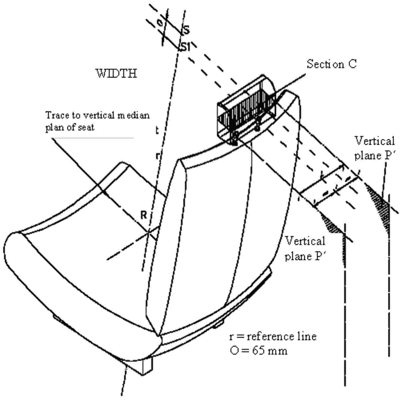
6.6. Determination of the width of the head restraint
(see figure 2 of annex 4 to this Regulation)
|
6.6.1. |
The plane S1, perpendicular to the reference line and situated 65 mm below the tangent S defined in paragraph 6.5.3 above, determines a section in the head restraint bounded by the outline C. |
|
6.6.2. |
The width of the head restraint to be taken into consideration in implementing the requirements of paragraph 5.11 above, is the distance ‘L’ measured in the plane S1 between the vertical longitudinal planes P and P’. |
|
6.6.3. |
The width of the head restraint shall if necessary also be determined in the plane perpendicular to the reference line 635 mm above the R point of the seat, this distance being measured along the reference line. |
6.7. Determination of distance ‘a’ of head restraint gaps
(see annex 8 to this Regulation)
|
6.7.1. |
The distance ‘a’ shall be determined for each gap and in relation to the front face of the head restraint, by means of a sphere having a diameter of 165 mm. |
|
6.7.2. |
The sphere shall be put into contact with the gap in a point of the gap area which allows the maximum sphere intrusion, considering no load is to be applied. |
|
6.7.3. |
The distance between the two points of contact of the sphere with the gap will constitute the distance ‘a’ to be considered for the evaluation of the provisions under paragraphs 5.9 and 5.10 above. |
6.8. Tests for checking energy dissipation on the seat-back and head restraint
6.8.1. The surfaces of the rear parts of seats to be checked are those situated in the areas defined below which can be contacted by a 165 mm diameter sphere when the seat is mounted in the vehicle.
6.8.1.1. Area 1
|
6.8.1.1.1. |
In the case of separate seats without head restraints, this area shall include the rear part of the seat-back between the longitudinal vertical planes situated at 100 mm on either side of the longitudinal median plane of the seat centre line, and above a plane perpendicular to the reference line 100 mm below the top of the seat-back. |
|
6.8.1.1.2. |
In the case of bench seats without head restraints, this area shall extend between the longitudinal vertical planes situated at 100 mm on either side of the longitudinal median plane of each designated outboard seating position defined by the manufacturer and above a plane perpendicular to the reference line 100 mm below the top of the seat-back. |
|
6.8.1.1.3. |
In the case of seats or bench seats with head restraints, this area shall extend between the longitudinal vertical planes, on either side of and 70 mm from the longitudinal median plane of the seat or of the seating position concerned and situated above the plane perpendicular to the reference line 635 mm from the R point. For the test, the head restraint, if adjustable shall be placed in the most unfavourable position (generally the highest) permitted by its adjustment system. |
6.8.1.2. Area 2
|
6.8.1.2.1. |
In the case of seats or bench seats without head restraints and seats or bench seats with detachable or separate head restraints, area 2 shall extend above a plane perpendicular to the reference line 100 mm distant from the top of the seat-back, other than parts of area 1. |
|
6.8.1.2.2. |
In the case of seats or bench seats with integrated head restraints, area 2 shall extend above a plane perpendicular to the reference line 440 mm distant from the R point of the seat or of the seating position concerned, other than parts of area 1. |
6.8.1.3. Area 3
|
6.8.1.3.1. |
Area 3 is defined as the part of the back of the seat or the bench seats situated above the horizontal planes defined in paragraph 5.2.4.1.3 above, excluding parts situated in area 1 and area 2. |
6.9. Equivalent test methods
If a test method other than those specified in paragraphs 6.2, 6.3, 6.4 above and annex 6 is used, its equivalence shall be proved.
7. CONFORMITY OF PRODUCTION
The conformity of production procedures shall comply with those set out in the Agreement, appendix 2 (E/ECE/324-E/ECE/TRANS/505/Rev.2), with the following requirements:
|
7.1. |
Every vehicle approved pursuant to this Regulation shall be so manufactured as to conform to the type approved by meeting the requirements set out in paragraph 5 above. However, in the case of head restraints as defined in paragraph 2.12.2 and 2.12.3 above, nothing shall prevent the vehicle from conforming to the vehicle type approved, even if it is marketed with seats not fitted with head restraints. |
|
7.2. |
The competent authority which granted type approval may at any time verify the conformity control methods applied for each production unit. The authority may also carry out random checks on serially-manufactured vehicles in respect to the requirements set out in paragraph 5 above. |
8. PENALTIES FOR NON-CONFORMITY OF PRODUCTION
|
8.1. |
The approval granted in respect of a vehicle type pursuant to this Regulation may be withdrawn if the requirements laid down in paragraph 7.1 above are not complied with or if the vehicles fail in the checks prescribed in paragraph 7 above. |
|
8.2. |
If a Party to the Agreement applying this Regulation withdraws an approval it has previously granted, it shall forthwith so notify the other Contracting Parties applying this Regulation by means of a communication form conforming to the model in annex 1 to this Regulation. |
9. MODIFICATIONS OF THE VEHICLE TYPE AND EXTENSION OF APPROVAL WITH RESPECT TO THE SEATS, THEIR ANCHORAGES AND/OR THEIR HEAD RESTRAINTS
|
9.1. |
Every modification of the vehicle type with respect to the seats, their anchorages and/or their head restraints shall be notified to the administrative department which approved the vehicle type. The department may then either:
|
|
9.2. |
Confirmation or refusal of approval, specifying the modifications, shall be communicated to the Parties to the Agreement applying this Regulation by means of the procedure laid down in paragraph 4.3 above. |
|
9.3. |
The competent authority issuing the extension of approval shall assign a series number for such an extension and inform thereof the other Parties to the 1958 Agreement applying this Regulation by means of a communication form conforming to the model in annex 1 to this Regulation. |
10. PRODUCTION DEFINITELY DISCONTINUED
|
10.1. |
If the holder of the approval completely ceases to manufacture a device approved in accordance with this Regulation, he shall so inform the authority which granted the approval. Upon receiving the relevant communication that authority shall inform thereof the other Parties to the 1958 Agreement applying this Regulation by means of a communication form conforming to the model in annex 1 to this Regulation. |
11. INSTRUCTIONS FOR USE
|
11.1. |
For seats fitted with adjustable head restraints, the manufacturers shall provide instructions on how to operate, adjust, lock and, where applicable, remove the head restraints. |
12. NAMES AND ADDRESSES OF TECHNICAL SERVICES RESPONSIBLE FOR CONDUCTING APPROVAL TESTS AND OF ADMINISTRATIVE DEPARTMENTS
The Parties to the Agreement applying this Regulation shall communicate to the United Nations Secretariat the names and addresses of the technical services responsible for conducting approval tests and of the administrative departments which grant approval and to which forms certifying approval or extension or refusal or withdrawal of approval, issued in other countries, are to be sent.
13. TRANSITIONAL PROVISIONS
|
13.1. |
As from the official date of entry into force of the 06 series of amendments, no Contracting Party applying this Regulation shall refuse to grant ECE approvals under this Regulation as amended by the 06 series of amendments. |
|
13.2. |
As from 1 October 1999, Contracting Parties applying this Regulation shall grant ECE approvals only if the requirements of this Regulation, as amended by the 06 series of amendments, are satisfied. |
|
13.3. |
As from 1 October 2001, Contracting Parties applying this Regulation may refuse to recognize approvals which were not granted in accordance with the 06 series of amendments to this Regulation. |
|
13.4. |
As from the official date of entry into force of the 07 series of amendments, no Contracting Party applying this Regulation shall refuse to grant ECE approvals under this Regulation as amended by the 07 series of amendments. |
|
13.5. |
As from 24 months after the date of entry into force of the 07 series of amendments, Contracting Parties applying this Regulation shall grant ECE approval only if the vehicle type to be approved complies with the requirements of this Regulation as amended by the 07 series of amendments. |
|
13.6. |
As from 48 months after the date of entry into force of the 07 series of amendments, existing approvals to this Regulation shall cease to be valid, except in the case of vehicle types which comply with the requirements of this Regulation as amended by the 07 series of amendments. |
|
13.7. |
As from the official date of entry into force of the 08 series of amendments, no Contracting Party applying this Regulation shall refuse to grant ECE approvals under this Regulation as amended by the 08 series of amendments. |
|
13.8. |
As from 24 months after the date of entry into force of the 08 series of amendments, Contracting Parties applying this Regulation shall grant ECE approvals only if the requirements of this Regulation, as amended by the 08 series of amendments, are satisfied. |
|
13.9. |
As from 36 months after the date of entry into force of the 08 series of amendments, Contracting Parties applying this Regulation may refuse to recognize approvals which were not granted in accordance with the 08 series of amendments to this Regulation. |
|
13.10. |
Notwithstanding paragraphs 13.8 and 13.9, approvals of the vehicle categories which are not affected by the 08 series of amendments shall remain valid and Contracting Parties applying the Regulation shall continue to accept them. |
|
13.11. |
As long as there are no requirements forbidding side-facing seats in their national requirements at the time of acceding to this Regulation, Contracting Parties may continue to allow the fitting of side-facing seats for the purpose of national approval and in this case these bus categories cannot be type approved under this Regulation |
|
13.12. |
The exemption referred to in paragraph 5.1.3 shall cease to have effect on 20 October 2010. It may be extended if reliable accident statistics are available and there has been further development of restraint systems. |
(1) As defined in Annex 7 to the Consolidated Resolution on the Construction of vehicles (R.E.3), document TRANS/WP.29/78/Rev.1/Amend.2, as last amended by Amendment 4.
(2) 1 for Germany, 2 for France, 3 for Italy, 4 for the Netherlands, 5 for Sweden, 6 for Belgium, 7 for Hungary, 8 for the Czech Republic, 9 for Spain, 10 for Serbia, 11 for the United Kingdom, 12 for Austria, 13 for Luxembourg, 14 for Switzerland, 15 (vacant), 16 for Norway, 17 for Finland, 18 for Denmark, 19 for Romania, 20 for Poland, 21 for Portugal, 22 for the Russian Federation, 23 for Greece, 24 for Ireland, 25 for Croatia, 26 for Slovenia, 27 for Slovakia, 28 for Belarus, 29 for Estonia, 30 (vacant), 31 for Bosnia and Herzegovina, 32 for Latvia, 33 (vacant), 34 for Bulgaria, 35 (vacant), 36 for Lithuania, 37 for Turkey, 38 (vacant), 39 for Azerbaijan, 40 for The former Yugoslav Republic of Macedonia, 41 (vacant), 42 for the European Community (Approvals are granted by its Member States using their respective ECE symbol), 43 for Japan, 44 (vacant), 45 for Australia, 46 for Ukraine, 47 for South Africa, 48 for New Zealand, 49 for Cyprus, 50 for Malta, 51 for the Republic of Korea, 52 for Malaysia, 53 for Thailand, 54 and 55 (vacant) and 56 for Montenegro. Subsequent numbers shall be assigned to other countries in the chronological order in which they ratify or accede to the Agreement Concerning the Adoption of Uniform Technical Prescriptions for Wheeled Vehicles, Equipment and Parts which can be Fitted and/or be Used on Wheeled Vehicles and the Conditions for Reciprocal Recognition of Approvals Granted on the Basis of these Prescriptions, and the numbers thus assigned shall be communicated by the Secretary-General of the United Nations to the Contracting Parties to the Agreement.
(3) Vehicles of category M2, which are approved to this Regulation as an alternative to Regulation No 80 (in line with paragraph 1.2 to that Regulation) shall also meet the requirements of this paragraph.
ANNEX 1
COMMUNICATION
(maximum format: A4 (210 × 297 mm))


ANNEX 2
ARRANGEMENTS OF APPROVAL MARKS
MODEL A
(see paragraphs 4.4, 4.4.1, 4.4.2 and 4.4.3 of this Regulation)
Vehicle with at least one seat fitted or capable of being fitted with a head restraint

The above approval mark when affixed to a vehicle shows that the vehicle type concerned, with regard to the strength of the seats fitted or capable of being fitted with head restraints and with regard to characteristics of the head restraints, has been approved in the Netherlands (E4) pursuant to Regulation No 17, under the approval number 082439. The first two digits of the approval number indicate that the Regulation already contained the 08 series of amendments at the time of approval. The above approval mark also shows that the vehicle type was approved pursuant to Regulation No 17 with regard to the strength of any seats on the vehicle which are not fitted or capable of being fitted with head restraints.
MODEL B
(see paragraphs 4.4, 4.4.1 and 4.4.2 of this Regulation)
Vehicle with seats not fitted or not capable of being fitted with head restraints

The above approval mark when affixed to a vehicle shows that the vehicle type has seats not fitted or capable of being fitted with head restraints, and has, with regard to the strength of the seats and their anchorages, been approved in the Netherlands (E4) pursuant to Regulation No 17 under the approval number 082439. The first two digits of the approval number indicate that the Regulation already contained the 08 series of amendments at the time of approval.
MODEL C
(see paragraph 4.5 of this Regulation)
Vehicle with at least one seat fitted or capable of being fitted with a head restraint

The above approval mark when affixed to a vehicle shows that the vehicle type has at least one seat fitted or capable of being fitted with a head restraint, and was approved in the Netherlands (E4) pursuant to Regulations No 17 and No 33 (1).
The approval numbers indicate that, on the dates when approval was granted, Regulation No 17 included the 08 series of amendments but Regulation No 33 was still in its original form. The above approval mark also shows that the vehicle type was approved pursuant to Regulation No 17 with regard to the strength of any seats on the vehicle which are not fitted or capable of being fitted with head restraints.
MODEL D
(see paragraph 4.5 of this Regulation)
Vehicle with seats not fitted or not capable of being fitted with head restraints

The above approval mark when affixed to a vehicle shows that the vehicle type has seats not fitted or capable of being fitted with head restraints, and was approved in the Netherlands (E4) pursuant to Regulations No 17 and No 33 (1). The approval numbers indicate that, on the dates when approval was granted, Regulation No 17 included the 08 series of amendments but Regulation No 33 was still in its original form.
(1) The second number is given merely as an example.
ANNEX 3
Procedure for determining the ‘H’ point and the actual torso angle for seating positions in motor vehicles
1. PURPOSE
The procedure described in this annex is used to establish the ‘H’ point location and the actual torso angle for one or several seating positions in a motor vehicle and to verify the relationship of measured data to design specifications given by the vehicle manufacturer (1).
2. DEFINITIONS
For the purposes of this annex:
|
2.1. |
‘Reference data’ means one or several of the following characteristics of a seating position:
|
|
2.2. |
‘Three-dimensional “H” point machine’ (3-D H machine) means the device used for the determination of ‘H’ points and actual torso angles. This device is described in appendix 1 to this annex; |
|
2.3. |
‘“H” point’ means the pivot centre of the torso and thigh of the 3-D H machine installed in the vehicle seat in accordance with paragraph 4 below. The ‘H’ point is located in the centre of the centreline of the device which is between the ‘H’ point sight buttons on either side of the 3-D H machine. The ‘H’ point corresponds theoretically to the ‘R’ point (for tolerances see paragraph 3.2.2 below). Once determined in accordance with the procedure described in paragraph 4, the ‘H’ point is considered fixed in relation to the seat-cushion structure and to move with it when the seat is adjusted; |
|
2.4. |
‘“R” point’ or ‘seating reference point’ means a design point defined by the vehicle manufacturer for each seating position and established with respect to the three-dimensional reference system; |
|
2.5. |
‘Torso-line’ means the centreline of the probe of the 3-D H machine with the probe in the fully rearward position; |
|
2.6. |
‘Actual torso angle’ means the angle measured between a vertical line through the ‘H’ point and the torso line using the back angle quadrant on the 3-D H machine. The actual torso angle corresponds theoretically to the design torso angle (for tolerances see paragraph 3.2.2 below); |
|
2.7. |
‘Design torso angle’ means the angle measured between a vertical line through the ‘R’ point and the torso line in a position which corresponds to the design position of the seat-back established by the vehicle manufacturer; |
|
2.8. |
‘Centre plane of occupant’ (C/LO) means the median plane of the 3-D H machine positioned in each designated seating position; it is represented by the co-ordinate of the ‘H’ point on the ‘Y’ axis. For individual seats, the centre plane of the seat coincides with the centre plane of the occupant. For other seats, the centre plane of the occupant is specified by the manufacturer; |
|
2.9. |
‘Three dimensional reference system’ means a system as described in appendix 2 to this annex; |
|
2.10. |
‘Fiducial marks’ are physical points (holes, surfaces, marks or indentations) on the vehicle body as defined by the manufacturer; |
|
2.11. |
‘Vehicle measuring attitude’ means the position of the vehicle as defined by the co-ordinates of fiducial marks in the three-dimensional reference system. |
3. REQUIREMENTS
3.1. Data presentation
For each seating position where reference data are required in order to demonstrate compliance with the provisions of the present Regulation, all or an appropriate selection of the following data shall be presented in the form indicated in appendix 3 to this annex:
|
3.1.1. |
the co-ordinates of the ‘R’ point relative to the three-dimensional reference system; |
|
3.1.2. |
the design torso angle; |
|
3.1.3. |
all indications necessary to adjust the seat (if it is adjustable) to the measuring position set out in paragraph 4.3 below. |
3.2. Relationship between measured data and design specifications
|
3.2.1. |
The co-ordinates of the ‘H’ point and the value of the actual torso angle obtained by the procedure set out in paragraph 4 below shall be compared, respectively, with the co-ordinates of the ‘R’ point and the value of the design torso angle indicated by the vehicle manufacturer. |
|
3.2.2. |
The relative positions of the ‘R’ point and the ‘H’ point and the relationship between the design torso angle and the actual torso angle shall be considered satisfactory for the seating position in question if the ‘H’ point, as defined by its co-ordinates, lies within a square of 50 mm side length with horizontal and vertical sides whose diagonals intersect at the ‘R’ point, and if the actual torso angle is within 5 degree of the design torso angle. |
|
3.2.3. |
If these conditions are met, the ‘R’ point and the design torso angle, shall be used to demonstrate compliance with the provisions of this Regulation. |
|
3.2.4. |
If the ‘H’ point or the actual torso angle does not satisfy the requirements of paragraph 3.2.2 above, the ‘H’ point and the actual torso angle shall be determined twice more (three times in all). If the results of two of these three operations satisfy the requirements, the conditions of paragraph 3.2.3 above shall apply. |
|
3.2.5. |
If the results of at least two of the three operations described in paragraph 3.2.4 above do not satisfy the requirements of paragraph 3.2.2 above, or if the verification cannot take place because the vehicle manufacturer has failed to supply information regarding the position of the ‘R’ point or regarding the design torso angle, the centroid of the three measured points or the average of the three measured angles shall be used and be regarded as applicable in all cases where the ‘R’ point or the design torso angle is referred to in this Regulation. |
4. PROCEDURE FOR ‘H’ POINT AND ACTUAL TORSO ANGLE DETERMINATION
|
4.1. |
The vehicle shall be preconditioned at the manufacturer’s discretion, at a temperature of 20 ± 10 °C to ensure that the seat material reaches room temperature. If the seat to be checked has never been sat upon, a 70 to 80 kg person or device shall sit on the seat twice for one minute to flex the cushion and back. At the manufacturer’s request, all seat assemblies shall remain unloaded for a minimum period of 30 minutes prior to installation of the 3-D H machine. |
|
4.2. |
The vehicle shall be at the measuring attitude defined in paragraph 2.11 above. |
|
4.3. |
The seat, if it is adjustable, shall be adjusted first to the rearmost normal driving or riding position, as indicated by the vehicle manufacturer, taking into consideration only the longitudinal adjustment of the seat, excluding seat travel used for purposes other than normal driving or riding positions. Where other modes of seat adjustment exist (vertical, angular, seat-back, etc.) these will be then adjusted to the position specified by the vehicle manufacturer. For suspension seats, the vertical position shall be rigidly fixed corresponding to a normal driving position as specified by the manufacturer. |
|
4.4. |
The area of the seating position contacted by the 3-D H machine shall be covered by a muslin cotton, of sufficient size and appropriate texture, described as a plain cotton fabric having 18,9 threads per cm2 and weighing 0,228 kg m2 or knitted or non-woven fabric having equivalent characteristics. If the test is run on a seat outside the vehicle, the floor on which the seat is placed shall have the same essential characteristics (2) as the floor of the vehicle in which the seat is intended to be used. |
|
4.5. |
Place the seat and back assembly of the 3-D H machine so that the centre plane of the occupant (C/LO) coincides with the centre plane of the 3-D H machine. At the manufacturer’s request, the 3-D H machine may be moved inboard with respect to the C/LO if the 3-D H machine is located so far outboard that the seat edge will not permit levelling of the 3-D H machine. |
|
4.6. |
Attach the foot and lower leg assemblies to the seat pan assembly, either individually or by using the T-bar and lower leg assembly. A line through the ‘H’ point sight buttons shall be parallel to the ground and perpendicular to the longitudinal centre plane of the seat. |
|
4.7. |
Adjust the feet and leg positions of the 3-D H machine as follows:
|
|
4.8. |
Apply lower leg and thigh weights and level the 3-D H machine. |
|
4.9. |
Tilt the back pan forward against the forward stop and draw the 3-D H machine away from the seat-back using the T-bar. Reposition the 3-D H machine on the seat by one of the following methods:
|
|
4.10. |
Apply a 100 ± 10 N load to the back and pan assembly of the 3-D H machine at the intersection of the hip angle quadrant and the T-bar housing. The direction of load application shall be maintained along a line passing by the above intersection to a point just above the thigh bar housing (see figure 2 of appendix 1 to this annex). Then carefully return the back pan to the seat-back. Care must be exercised throughout the remainder of the procedure to prevent the 3-D H machine from sliding forward. |
|
4.11. |
Install the right and left buttock weights and then, alternately, the eight torso weights. Maintain the 3-D H machine level. |
|
4.12. |
Tilt the back pan forward to release the tension on the seat-back. Rock the 3-D H machine from side to side through 10 degrees arc (5 degrees to each side of the vertical centre plane) for three complete cycles to release any accumulated friction between the 3-D H machine and the seat. During the rocking action, the T-bar of the 3-D H machine may tend to diverge from the specified horizontal and vertical alignment. The T-bar must therefore be restrained by applying an appropriate lateral load during the rocking motions. Care shall be exercised in holding the T-bar and rocking the 3-D H machine to ensure that no inadvertent exterior loads are applied in a vertical or fore and aft direction. The feet of the 3-D H machine are not to be restrained or held during this step. If the feet change position, they should be allowed to remain in that attitude for the moment. Carefully return the back pan to the seat-back and check the two spirit levels for zero position. If any movement of the feet has occurred during the rocking operation of the 3-D H machine, they must be repositioned as follows: Alternately, lift each foot off the floor the minimum necessary amount until no additional foot movement is obtained. During this lifting, the feet are to be free to rotate; and no forward or lateral loads are to be applied. When each foot is placed back in the down position, the heel is to be in contact with the structure designed for this. Check the lateral spirit level for zero position; if necessary, apply a lateral load to the top of the back pan sufficient to level the 3-D H machine’s seat pan on the seat. |
|
4.13. |
Holding the T-bar to prevent the 3-D H machine from sliding forward on the seat cushion, proceed as follows:
|
|
4.14. |
Take all measurements:
|
|
4.15. |
If a re-run of the installation of the 3-D H machine is desired, the seat assembly should remain unloaded for a minimum period of 30 minutes prior to the re-run. The 3-D H machine should not be left loaded on the seat assembly longer than the time required to perform the test. |
|
4.16. |
If the seats in the same row can be regarded as similar (bench seat, identical seats, etc.) only one ‘H’ point and one ‘actual torso angle’ shall be determined for each row of seats, the 3-D H machine described in appendix 1 to this annex being seated in a place regarded as representative for the row. This place shall be:
|
(1) In any seating position other than front seats where the ‘H’ point cannot be determined using the ‘three-dimensional “H” point machine’ or procedures, the ‘R’ point indicated by the manufacturer may be taken as a reference at the discretion of the competent authority.
(2) Tilt angle, height difference with a seat mounting, surface texture, etc.
APPENDIX 1
DESCRIPTION OF THE THREE-DIMENSIONAL ‘H’ POINT MACHINE (1)
(3-D H machine)
1. BACK AND SEAT PANS
The back and seat pans are constructed of reinforced plastic and metal; they stimulate the human torso and thigh and are mechanically hinged at the ‘H’ point. A quadrant is fastened to the probe hinged at the ‘H’ point to measure the actual torso angle. An adjustable thigh bar, attached to the seat pan, establishes the thigh centreline and serves as a baseline for the hip angle quadrant.
2. BODY AND LEG ELEMENTS
Lower leg segments are connected to the seat pan assembly at the T-bar joining the knees, which is a lateral extension of the adjustable thigh bar. Quadrants are incorporated in the lower leg segments to measure knee angles. Shoe and foot assemblies are calibrated to measure the foot angle. Two spirit levels orient the device in space. Body element weights are placed at the corresponding centres of gravity to provide seat penetration equivalent to a 76 kg male. All joints of the 3-D H machine should be checked for free movement without encountering noticeable friction.
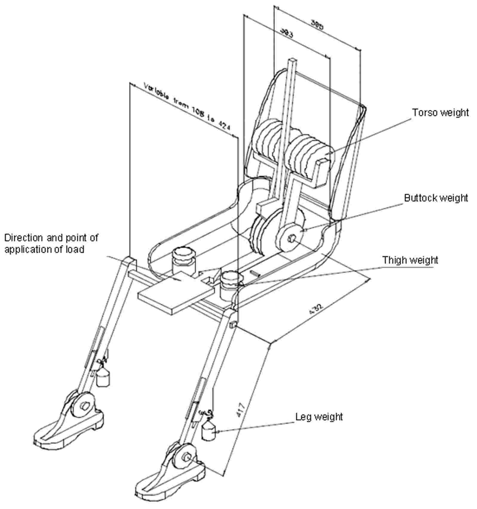
Figure 1
3-D H machine elements designation

Figure 2
Dimensions of the 3-D H machine elements and load distribution
(Dimensions in millimeters)
(1) For details of the construction of the 3-D H machine refer to Society of Automotive Engineers (SAE), 400 Commonwealth Drive, Warrendale, Pennsylvania 15096, United States of America.
The machine corresponds to that described in ISO Standard 6549 : 1980.
APPENDIX 2
THREE-DIMENSIONAL REFERENCE SYSTEM
|
1. |
The three-dimensional reference system is defined by three orthogonal planes established by the vehicle manufacturer (see figure) (1). |
|
2. |
The vehicle measuring attitude is established by positioning the vehicle on the supporting surface such that the co-ordinates of the fiducial marks correspond to the values indicated by the manufacturer. |
|
3. |
The co-ordinates of the ‘R’ point and the ‘H’ point are established in relation to the fiducial marks defined by the vehicle manufacturer. |
Figure
Three-dimensional reference system

(1) The reference system corresponds to ISO standard 4130 : 1978.
APPENDIX 3
REFERENCE DATA CONCERNING SEATING POSITIONS
1. CODING OF REFERENCE DATA
Reference data are listed consecutively for each seating position. Seating positions are identified by a two-digit code. The first digit is an Arabic numeral and designates the row of seats, counting from the front to the rear of the vehicle. The second digit is a capital letter which designates the location of the seating position in a row, as viewed in the direction of forward motion of the vehicle; the following letters shall be used:
|
L |
= |
left |
|
C |
= |
centre |
|
R |
= |
right |
2. DESCRIPTION OF VEHICLE MEASURING ATTITUDE
2.1. Co-ordinates of fiducial marks
X …
Y …
Z …
3. LIST OF REFERENCE DATA
3.1. Seating position: …
3.1.1. Co-ordinates of ‘R’ point
X …
Y …
Z …
3.1.2. Design torso angle: …
3.1.3. Specification for seat adjustment (1)
horizontal: …
vertical: …
angular: …
torso angle: …
|
Note: |
List reference data for further seating positions under 3.2, 3.3, etc. |
(1) Strike out what does not apply.
ANNEX 4
Determination of the height and width of head restraints
Figure 1
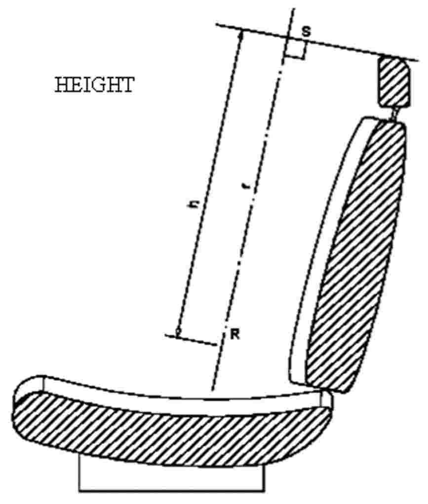
Figure 2
ANNEX 5
DETAILS OF LINES AND MEASUREMENTS TAKEN DURING TESTS

|
1. |
Original unloaded position. |
|
2a. |
Displaced position by applying to the manikin’s back a moment of 373 Nm about the R point, defining the position of the displaced reference line r1. |
|
2b. |
Displaced position by applying to the 165 mm sphere a force F producing a moment of 373 Nm about the R point, keeping the displaced reference line r1 in place. |
|
3. |
Position after displacement by the force F increased to 890 N. |

ANNEX 6
TEST PROCEDURE FOR CHECKING ENERGY DISSIPATION
1. INSTALLATION, TEST APPARATUS, RECORDING INSTRUMENTS AND PROCEDURE
1.1. Setting up
The seat, as mounted in the vehicle, shall be firmly secured to the test bench with the attachment parts provided by the manufacturer, so as to remain stationary when the impact is applied.
The seat-back, if adjustable, shall be locked in the position specified in paragraph 6.1.1 of this Regulation.
If the seat is fitted with a head restraint, the head restraint shall be mounted on the seat-back as in the vehicle. Where the head restraint is separate, it shall be secured to the part of the vehicle structure to which it is normally attached.
If the head restraint is adjustable, it shall be placed in the most unfavourable position allowed by its adjusting systems.
1.2. Test apparatus
|
1.2.1. |
This apparatus consists of a pendulum whose pivot is supported by ball-bearings and whose reduced mass (1) at its centre of percussion is 6,8 kg. The lower extremity of the pendulum consists of a rigid headform 165 mm in diameter whose centre is identical with the centre of percussion of the pendulum. |
|
1.2.2. |
The headform shall be fitted with two accelerometers and a speed-measuring device, all capable of measuring values in the direction of impact. |
1.3. Recording instruments
The recording instruments used shall be such that measurements can be made with the following degrees of accuracy:
|
1.3.1. |
Acceleration:
|
|
1.3.2. |
Speed:
|
|
1.3.3. |
Time recording:
|
1.4. Test procedure
1.4.1. Tests on the seat-back
With the seat installed as indicated in paragraph 1.1 of this annex, the direction of impact from the rear towards the front shall be situated in a longitudinal plane at an angle of 45° from the vertical.
The impact points shall be selected by the test laboratory in area 1 as defined in paragraph 6.8.1.1 of this Regulation, or if necessary in area 2 as defined in paragraph 6.8.1.2 of this Regulation, on surfaces exhibiting radii of curvature less than 5 mm.
1.4.2. Tests on the head restraint
The head restraint shall be fitted and adjusted as indicated in paragraph 1.1 of this annex. Impacts shall be performed on points selected by the test laboratory in area 1 as defined in paragraph 6.8.1.1 of this Regulation, and possibly in area 2 as defined in paragraph 6.8.1.2 of this Regulation, on surfaces exhibiting radii of curvature less than 5 mm.
|
1.4.2.1. |
For the rear face, the direction of impact from the rear towards the front shall be in a longitudinal plane at an angle of 45° from the vertical. |
|
1.4.2.2. |
For the front face, the direction of impact from the front towards the rear shall be horizontal in a longitudinal plane. |
|
1.4.2.3. |
The front and rear zones are respectively bounded by the horizontal plane tangential to the top of the head restraint as determined in paragraph 6.5 of this Regulation. |
1.4.3. The headform shall strike the test item at a speed of 24,1 km/h: this speed shall be achieved either by the mere energy of propulsion or by using an additional impelling device.
2. RESULTS
The deceleration rate shall be taken as the average of the readings on the two accelerometers.
3. EQUIVALENT PROCEDURES (see paragraph 6.9 of this Regulation).
(1) The relationship of the reduced mass ‘mr’ of the pendulum to the total mass ‘m’ of the pendulum at a distance ‘a’ between the centre of percussion and the axis of rotation and at a distance ‘l’ between the centre of gravity and the axis of rotation is given by the formula:

ANNEX 7
Method for testing the strength of seat anchorages and their adjustment, locking and displacement systems
1. TEST OF RESISTANCE TO INERTIA EFFECTS
|
1.1. |
The seats to be tested shall be mounted on the vehicle body for which they are designed. This vehicle body shall be firmly anchored on a test trolley as prescribed in the following paragraphs. |
|
1.2. |
The method used for anchoring the vehicle body on the test trolley shall not result in a reinforcement of the seat anchorages. |
|
1.3. |
The seats and their parts shall be adjusted and locked as prescribed in paragraph 6.1.1 and in one of the positions described in paragraph 6.3.3 or 6.3.4 of this Regulation. |
|
1.4. |
If the seats of a group do not present essential differences in the sense of paragraph 2.2 of this Regulation, the tests prescribed in paragraphs 6.3.1 and 6.3.2 of this Regulation may be carried out with one seat adjusted to its foremost position and the other seat adjusted to its rearmost position. |
|
1.5. |
The trolley deceleration or acceleration is measured with data channels of frequency class (CFC) 60 corresponding to the characteristics of International Standard ISO 6487 (2002). |
2. COLLISION TEST OF THE COMPLETE VEHICLE AGAINST A RIGID BARRIER
|
2.1. |
The barrier shall consist of a block of reinforced concrete of not less than 3 m width, not less than 1,5 m height and not less than 0,6 m thickness. The front face shall be perpendicular to the final part of the run-up track and shall be covered with plywood boards 19 ± 1 mm thick. At least 90 tonnes of earth shall be compressed behind the block of reinforced concrete. The barrier of reinforced concrete and earth may be replaced by obstacles having the same front surface, provided that they give equivalent results. |
|
2.2. |
At the moment of impact the vehicle shall run free. It shall reach the obstacle on a course perpendicular to the collision wall; the maximum lateral misalignment allowed between the vertical median line of the front of the vehicle and the vertical median line of the collision wall shall be ± 30 cm; at the moment of impact the vehicle shall no longer be subjected to the action of any additional steering or propelling device. The speed on impact shall be between 48,3 km/h and 53,1 km/h. |
|
2.3. |
The fuel feed system shall be filled to at least 90 per cent of its capacity with fuel or an equivalent liquid. |
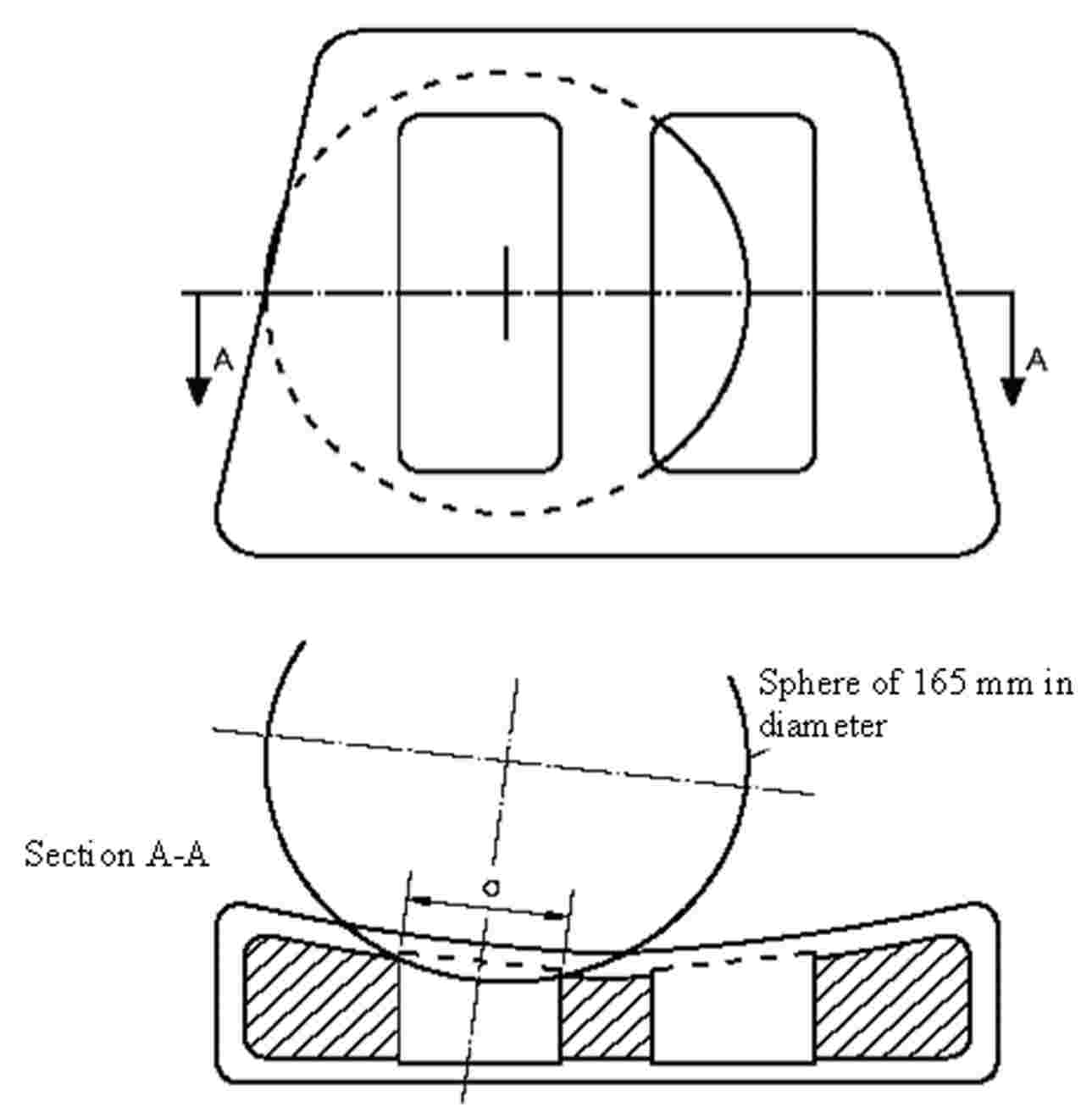
ANNEX 8
DETERMINATION OF DIMENSION ‘a’ OF HEAD RESTRAINT GAPS
Figure 1
Example of horizontal gaps
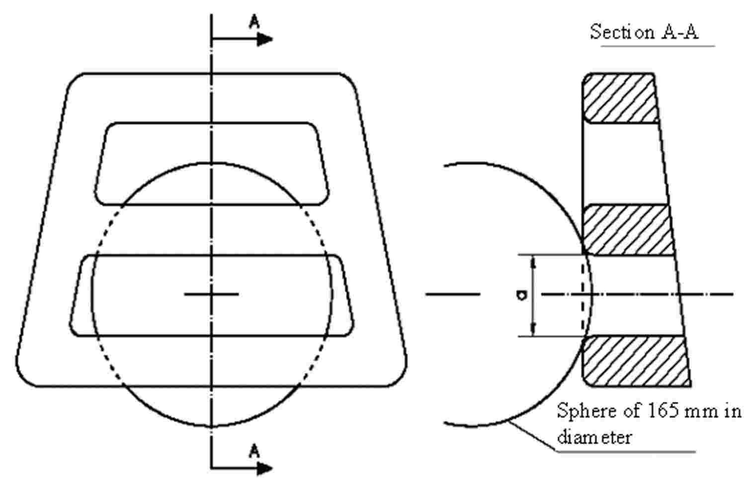
|
Note: |
Section A-A is to be made in a point of the gap area which allows the maximum sphere intrusion, without exerting any load. |
Figure 2
Example of vertical gaps
|
Note: |
Section A-A is to be made in a point of the gap area which allows the maximum sphere intrusion, without exerting any load. |
ANNEX 9
TEST PROCEDURE FOR DEVICES INTENDED TO PROTECT THE OCCUPANTS AGAINST DISPLACEMENT OF LUGGAGE
1. TEST BLOCKS
Rigid blocks, with the centre of inertia in the geometric centre.
|
Type 1 |
|
||||||
|
Type 2 |
|
2. TEST PREPARATION
2.1. Test of seat-backs (see figure 1)
2.1.1. General requirements
|
2.1.1.1. |
At the option of the car manufacturer, parts whose hardness is lower than 50 Shore A can be removed from the tested seat and head restraint for the tests. |
|
2.1.1.2. |
Two type 1 test blocks shall be placed on the floor of the luggage compartment. In order to determine the location of the test blocks in the longitudinal direction, they shall first be positioned such that their front side contacts that part of the vehicle which constitutes the forward boundary of the luggage compartment and that their lower side rests on the floor of the luggage compartment. They shall then be moved backwards and parallel to the longitudinal median plane of the vehicle until their geometrical centre has traversed a horizontal distance of 200 mm. If the dimensions of the luggage compartment do not allow a distance of 200 mm and if the rear seats are horizontally adjustable, these seats shall be moved forward to the limit of the adjustment range intended for normal occupant use, or to the position resulting in a distance of 200 mm, whichever is less. In other cases, the test blocks shall be placed as far as possible behind the rear seats. The distance between the longitudinal median plane of the vehicle and the inward facing side of each test block shall be 25 mm to obtain a distance of 50 mm between both blocks. |
|
2.1.1.3. |
During the test, the seats must be adjusted to ensure that the locking system cannot be released by external factors. If applicable, the seats shall be adjusted as follows: The longitudinal adjustment shall be secured one notch or 10 mm in front of the rearmost possible position of use specified by the manufacturer (for seats with independent vertical adjustment, the cushion shall be placed to its lowest possible position). The test shall be carried out with the seat-backs in their normal position of use. |
|
2.1.1.4. |
If the seat-back is fitted with a head restraint, the test must be carried out with the head restraint placed in the highest position, if adjustable. |
|
2.1.1.5. |
If the back(s) of the rear seat(s) can be folded down, they shall be secured in their upright normal position by the standard locking mechanism. |
|
2.1.1.6. |
Seats behind which the type 1 blocks cannot be installed are exempted from this test Figure 1 Positions of test blocks before test of rear seat-backs
|

2.1.2. Vehicles with more than two rows of seats
|
2.1.2.1. |
If the rearmost row of seats is removable and/or can be folded down by the user according to the manufacturer’s instructions in order to increase the luggage compartment area, then the seat row immediately in front of this rearmost row shall also be tested. |
|
2.1.2.2. |
However, in this case, the Technical Service, after consultation with the manufacturer, may decide not to test one of the two rearmost rows of seats if the seats and their attachments are of similar design and if the test requirement of 200 mm is respected. |
2.1.3. When there is a gap, allowing sliding of one type 1 block past the seats, then the test loads (two type 1 blocks) shall be installed behind the seats after agreement between the Technical Service and the manufacturer.
2.1.4. The exact test configuration shall be noted in the test report.
2.2. Test of partitioning systems
For the test of the partitioning systems above the seat-backs, the vehicle shall be fitted with a fixed raised test floor having a load surface that locates the centre of gravity of the test block centrally between the top edge of the bordering seat-back (without taking into account the head restraints) and the bottom edge of the roof lining. A type 2 test block is placed on the raised test floor with its largest surface 500 × 350 mm, centrally in relation to the longitudinal axis of the vehicle and with its surface 500 × 125 mm to the front. Partitioning systems behind which the type 2 test block cannot be installed are exempted from this test. The test block is placed directly in contact with the partitioning system. In addition, two type 1 test blocks are positioned in accordance with paragraph 2.1 in order to perform a simultaneous test on the seat-backs (see figure 2).
Figure 2
Testing of a partitioning system above the backrest

|
2.2.1. |
If the seat-back is fitted with a head restraint, the test must be carried out with the head restraint placed in the highest position, if adjustable. |
3. DYNAMIC TESTING OF SEAT-BACKS AND PARTITIONING SYSTEMS USED AS LUGGAGE RESTRAINT SYSTEMS
|
3.1. |
The body of the passenger car shall be anchored securely to a test sled, and this anchorage shall not act as reinforcement for seat-backs and the partitioning system. After the installation of the test blocks as described in paragraph 2.1 or 2.2, the passenger car body shall be decelerated or, at the choice of the applicant, accelerated such that the curve remains within the area of the graph in Annex 9, Appendix, and the total velocity change ΔV is 50 + 0/- 2 km/h. With the agreement of the manufacturer, the above described test pulse corridor can be used alternatively to fulfil the test of the seat strength according to paragraph 6.3.1. |
APPENDIX
Corridor of sled’s deceleration or acceleration as a function of time
(Simulation of frontal impact)
