LIST OF ANNEXES
|
ANNEX I: |
Scope, definition, application and granting of EEC type-approval, extension of approval, conformity of production |
|
ANNEX II: |
Example of an EEC approval marking |
|
ANNEX III: |
Information document for type-approved mechanical coupling devices |
|
ANNEX IV: |
EEC type-approval certificate for mechanical coupling devices |
|
ANNEX V: |
Requirements for mechanical coupling devices |
|
ANNEX VI: |
Testing of mechanical coupling devices |
|
ANNEX VII: |
Requirements for the attachment of mechanical coupling devices to vehicles |
|
ANNEX VIII: |
Information document for type-approved vehicles |
|
ANNEX IX: |
EEC type-approval certificate for vehicles |
ANNEX I
1. Scope
|
1.1. |
This Directive applies to the mechanical coupling devices for motor vehicles and their trailers and the attachment of these devices to the road vehicles, as described in Article 1 of this Directive. |
|
1.2. |
This Directive states the requirements which mechanical coupling devices intended for use between combinations of vehicles must satisfy in order to:
|
|
1.3. |
The coupling devices are classified according to type, and distinguishing between:
The classification is as follows:
|
2. DEFINITIONS
|
2.1. |
Mechanical coupling devices between motor vehicles and trailers are all parts and devices on the frames, load-bearing parts of the bodywork and chassis of the vehicles by means of which towing and towed vehicles are connected together. It also includes fixed or detachable parts for the attachment, adjustment or operation of the abovementioned coupling devices. |
|
2.1.1. |
The coupling balls and towing brackets in Section 1.3.1 are mechanical coupling devices employing a spherical device and brackets on the towing vehicle for connecting to the trailer by means of a coupling head. |
|
2.1.2. |
The coupling heads in Section 1.3.2 are mechanical coupling devices on the drawbar of trailers for connecting to a coupling ball on the towing vehicle. |
|
2.1.3. |
The drawbar couplings in Section 1.3.3 are mechanical coupling devices with a jaw and an automatic closing and locking pin on the towing vehicle for connecting to the trailer by means of a drawbar eye. |
|
2.1.4. |
The drawbar eyes in Section 1.3.4 are mechanical coupling devices on the drawbar of trailers having a parallel hole for connecting to the automatic drawbar couplings. |
|
2.1.5. |
The drawbars in Section 1.3.5 comprise overrun devices and similar items of equipment mounted on the front of the towed vehicle or to the vehicle chassis, which is suitable for coupling to a towing vehicle by means of drawbar eyes, coupling heads and similar coupling devices. Drawbars can be attached to the trailer so as to move freely in the vertical plane and therefore support no vertical load, so called hinged drawbars, or be fixed in the vertical plane so as to support a vertical load, so called rigid drawbars. Drawbars fixed in the vertical plane can be either rigid or sprung. Drawbars may also comprise more than one component, be adjustable or cranked. This Directive concerns drawbars only of the type which forms a separate unit, which is not part of the chassis of the towed vehicle. |
|
2.1.6. |
The drawbeams in Section 1.3.6 are all parts and devices placed between the coupling devices, such as coupling balls and drawbar couplings, and the frame (e.g. rear cross member), the load-bearing bodywork or the chassis of the towing vehicle. |
|
2.1.7. |
The fifth wheel coupling in Section 1.3.7 are plate-like coupling devices used on towing vehicles having an automatic coupling lock and connecting to the fifth wheel coupling pins in Section 1.3.8. |
|
2.1.8. |
The fifth wheel coupling pins in Section 1.3.8. are a coupling device in the form of a pin for mounting on a semi-trailer and connecting to the towing vehicle by means of a fifth wheel coupling. |
|
2.1.9. |
The mounting plates in Section 1.3.9 are all parts and devices used for attaching fifth wheel couplings to the frame of the towing vehicle. The mounting plate may have provision to move horizontally (i.e. sliding fifth wheel). |
|
2.1.10. |
Steering wedges are components mounted on semi-trailers which control positive steering of the trailer in conjunction with the fifth wheel coupling. |
|
2.1.11. |
Standard coupling devices are classified in Section 1.3. and conform to standard dimensions and standard characteristic values as given in this Directive. They are interchangeable within their class, independent of type and manufacturer. |
|
2.1.12. |
Non-standard coupling devices are those of Classes A to J which do not fall under the classification of standard coupling devices but which can be connected to standard coupling devices of the relevant classes. |
|
2.1.13. |
The miscellaneous coupling devices for transitional or exceptional use in Section 1.3.10 are mechanical coupling devices which do not belong to any of the Classes A to J (e.g. coupling devices according to existing national standards or for heavy transport). |
|
2.1.14. |
Remote control devices are devices which, in the case of an inaccessible coupling device, enable the coupling device to be operated from the side of the vehicle or from the driving cab. |
|
2.1.15. |
Remote indicators are indicating devices which indicate to the vehicle driver in his cab that coupling has been effected and the safety devices have engaged. |
|
2.1.16. |
A type of mechanical coupling device means a device which does not differ in such essential aspects as:
|
|
2.1.17. |
A coupling procedure is automatic if reversing the towing vehicle against the trailer is sufficient to engage the coupling completely and properly without any external intervention, to secure it automatically and to indicate proper engagement of the safety devices. An automatic coupling procedure requires the use of automatic couplings. |
|
2.1.18. |
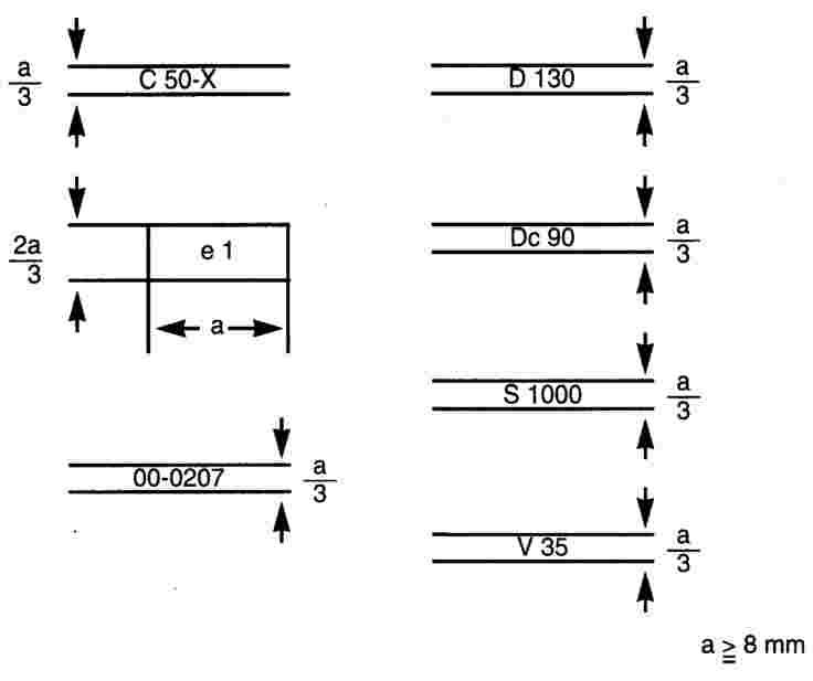
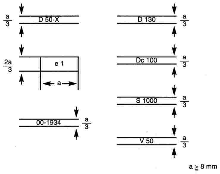
The ‘D-value’ is defined as the theoretical reference force for the horizontal force between towing vehicle and trailer. The D-value is taken as the basis for horizontal loads in the dynamic tests. For mechanical coupling devices unsuitable for transmitting vertical bearing loads the value is:
For mechanical coupling devices suitable for centre axle trailers the value is:
For fifth wheel couplings on towing tractors and vehicles of comparable type the value is:
where:
|

|
2.1.19. |
The ‘V-value’ is defined as the theoretical reference force for the amplitude of the vertical force between towing vehicle and centre axle trailers having a maximum mass exceeding 3,5 tonnes (see Section 2.1.21). The V-value is taken as a basis for the vertical test loads in the dynamic tests:
where:
|


|
2.1.20. |
‘Centre-axle trailer’ means a towed vehicle equipped with a towing device which cannot move vertically (in relation to the trailer), and in which the axle(s) is (are) positioned close to the centre of gravity of the vehicle (when uniformly loaded) such that only a small vertical load, not exceeding 10 % of the maximum mass of the trailer of 1 000 kg (whichever is the lesser) is transmitted to the drawing vehicle. The maximum mass of a centre-axle trailer to be taken into consideration shall be the mass transmitted to the ground by the axle(s) of the centre-axle trailer when coupled to the drawing vehicle and laden with a maximum load. |
|
2.1.2.1. |
For vehicles not falling clearly in any of the above categories they shall be treated in the same way as the type they most closely resemble. |
|
2.1.22. |
‘Vehicle type’ means vehicles which do not differ with respect to the following main characteristics: the structure, dimensions, shape and materials of the relevant parts concerning the fixing of the coupling device of the towing vehicle, or the front part in the case of a trailer, in so far as they have a bearing on the requirements of Annex VII. |
3. EEC TYPE-APPROVAL FOR A COMPONENT
3.1. Application for EEC type-approval
|
3.1.1. |
The application for EEC type-approval pursuant to Article 3 (4) of Directive 70/156/EEC of a type of a mechanical coupling device shall be submitted by the manufacturer. |
|
3.1.2. |
A model for the information document is given in Annex III. |
|
3.1.3. |
The following must be submitted to the technical service responsible for conducting the type-approval tests:
|
3.2. Marking of specimen
|
3.2.1. |
Each of the specimens of the particular type of coupling device in Section 3.1.1 for which an application for EEC component type approval has been submitted must be marked as follows: |
|
3.2.2. |
factory mark, trade name or manufacturer's name (and trade mark if appropriate); |
|
3.2.3. |
type and, if applicable, version; |
|
3.2.4. |
a sufficiently large space for the EEC approval mark and the additional information according to Section 3.3.4. |
3.3. Granting of EEC type-approval
|
3.3.1. |
If the relevant requirements are satisfied, EEC type-approval pursuant to Article 4 (3) and, if applicable, Article 4 (4) of Directive 70/156/EEC shall be granted. |
|
3.3.2. |
A model for the EEC type-approval certificate is given in Annex IV. |
|
3.3.3. |
An approval number in accordance with Annex VII to Directive 70/156/EEC shall be assigned to each type of mechanical coupling device approved. The same Member State may not assign the same number to another type of a mechanical coupling device. |
|
3.3.4. |
There shall be affixed, conspicuously and in a readily accessible place specified on the approval form, to every mechanical coupling device conforming to a type of mechanical coupling device approved under this Directive an international approval mark consisting of:
|
|
3.3.4.1. |
A rectangle surrounding the letter ‘e’ followed by the distinguishing number of the country which has granted approval. |
|
3.3.4.2. |
A two-digit number, indicating the number of the latest amendment of the Directive (for this Directive the number is 00), and Section 4 of the type-aproval number, as given on the EEC type-approval certificate (see Annex IV), near to the rectangle of the approval mark. |
|
3.3.4.3. |
The following supplementary marks placed anywhere close to the rectangle:
|
|
3.3.5. |
The approval mark shall be indelible and clearly legible even when the coupling device is attached to the vehicle. |
|
3.3.6. |
Annex II to this Directive gives examples of the arrangement of the approval mark. |
3.4. Modification of the type of mechanical coupling device and extension of EEC component type-approval
|
3.4.1. |
In the case of modification of a type approved pursuant to this Directive, the provisions of Article 5 of Directive 70/156/EEC shall apply. |
4. EEC TYPE-APPROVAL FOR A VEHICLE
4.1. Application for EEC type-approval
|
4.1.1. |
The application for EEC type-approval pursuant to Article 3 (4) of Directive 70/156/EEC of a vehicle type with regard to its type of a mechanical coupling device shall be submitted by the manufacturer. |
|
4.1.2. |
A model for the information document is given in Annex VIII. |
|
4.1.3. |
The following must be submitted to the technical service responsible for conducting the type-approval tests:
|
4.2. Granting of EEC type-approval
|
4.2.1. |
If the relevant requirements are satisfied, EEC type-approval pursuant to Article 4 (3) and (4) of Directive 70/156/EEC shall be granted. |
|
4.2.2. |
A model for the EEC type-approval certificate is given in Annex IX. |
|
4.2.3. |
An approval number in accordance with Annex VII to Directive 70/156/EEC shall be assigned to each type of vehicle approved. The same Member State shall not assign the same number to another type of vehicle. |
4.3. Modification of the type of vehicle and extension of EEC vehicle type-approval
|
4.3.1. |
In the case of modification of a type-approval pursuant to this Directive, the provisions of Article 5 of Directive 70/156/EEC shall apply. |
|
4.3.2. |
The holder of an EEC vehicle type-approval can apply for it to be extended to other types or classes of coupling devices. The competent authorities will grant such an extension on the following conditions:
|
|
4.3.3. |
In the case of standard coupling devices in classes A, C, D and G, EEC vehicle type-approval is also valid for other coupling devices of the same class without the need for a further mounting check and extension of EEC vehicle type-approval. |
5. REQUIREMENTS
|
5.1. |
The mechanical coupling devices between motor vehicles and trailers must be manufactured and attached in accordance with good engineering practice, and must be safe to operate. |
|
5.2. |
Safe coupling and uncoupling of the vehicles must be possible by a single person without the use of tools. Only automatic coupling devices which allow an automatic coupling procedure shall be employed for the coupling of trailers having a maximum mass of more than 3,5 tonnes. |
|
5.3. |
The mechanical coupling devices shall be so designed and manufactured that in normal use, with proper maintenance and the timely replacement of wearing parts, they will continue to function satisfactorily. |
|
5.4. |
Every coupling device must be accompanied by installation and operating instructions giving sufficient information for a competent person to install it on the vehicle and operate it properly. The instructions must be in the language or languages of the Member State in which the coupling device will be offered for sale. In the case of coupling devices supplied for assembly-line use by vehicle builders or bodybuilders, the provisions of installation and operating instructions for each coupling device can be dispensed with. It is then the responsibility of the vehicle builder or bodybuilder to ensure that the vehicle operator is provided with the information necessary for operating the coupling device. |
|
5.5. |
The materials that may be used are those for which the properties relevant to the application are laid down in a standard or those for which the properties are given in the documentation according to Section 3.1.2 of this Annex. |
|
5.6. |
All parts of the mechanical coupling devices whose failure could result in separation of the two vehicles must be made of steel. Other materials may be used provided equivalence has been demonstrated by the manufacturer to the satisfaction of the Technical Service. |
|
5.7. |
All couplings must be designed for positive mechanical engagement, and the closed position must be secured at least once by positive mechanical engagement, unless further requirements are stated in Annex V. |
|
5.8. |
The mechanical coupling devices must satisfy the requirements of Annex V. |
5.9. Loading requirements
|
5.9.1. |
Mechanical coupling devices are subject to the tests described in Annex VI. |
|
5.9.2. |
These tests must not cause any cracks, fractures or other visible external damage, or any excessive permanent distortion which would be detrimental to the satisfactory operation of the device. |
|
5.10. |
The installation of the mechanical coupling devices to the vehicle must be checked according to the requirements given in Annex VII. This requirement should apply to both EEC type-approval of a vehicle, when the vehicle type is provided with a mechanical coupling device as first equipment by the vehicle manufacturer, and EEC type-approval of a mechanical coupling device designed for a specific vehicle type. |
|
5.11. |
The abovementioned requirements and those of Annexes V, VI and VII are also applicable, as relevant, to miscellaneous coupling devices (Class S). |
6. CONFORMITY OF PRODUCTION
|
6.1. |
As a general rule, measures to ensure the conformity of production shall be taken in accordance with the provisions laid down in Article 10 of Directive 70/156/EEC. |
|
6.2. |
The normal frequency of inspections to be carried out by the competent authority shall be one per year. |
ANNEX II
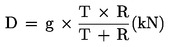
(a) Specimen EEC approval marking for a drawbar coupling
The coupling device with the EEC approval marking illustrated above is a non-standard drawbar coupling of Class C 50-X with a maximum permitted D value of 130 kN, a maximum permitted Dc value of 90 kN, a maximum permitted static vertical bearing load of 1 000 kg and a maximum permitted V-value of 35 kN, for which EEC component type-approval was granted in the Federal Republic of Germany (e 1) under the number 0207. The first two digits 00 indicate that this component was approved according to the original form of this Directive.
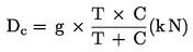
(b) Specimen EEC approval marking for a drawbar eye
The coupling device with the EEC approval marking illustrated above is a non-standard drawbar eye 50 of Class D 50-X for welding attachment having a D value of 130 kN, a Dc value of 100 kN, a maximum permitted static vertical bearing load of 1 000 kg and a maximum permitted V-value of 50 kN, for which EEC component type-approval was granted in the Federal Republic of Germany (e 1) under the number 1934. The first two digits 00 indicate that this component was approved according to the original form of this Directive.
(c) Specimen EEC approval mark for a fifth wheel coupling

The coupling device with the EEC approval marking illustrated above is a non-standard fifth wheel coupling of Class G 50-X having a maximum permitted D value of 180 kN and a maximum permitted fifth wheel load of 26 tonnes, for which EEC component type-approval was granted in the Federal Republic of Germany (e 1) under the number 0015. The first two digits 00 indicate that this component was approved according to the original form of this Directive.
(d) Specimen EEC approval marking for a fifth wheel coupling pin

The coupling device with the EEC approval marking illustrated above is a non-standard fifth wheel coupling pin of Class H 50-X having a D value of 162 kN for which EEC component type-approval was granted in the Federal Republic of Germany (e 1) under the number 1989. The first two digits 00 indicate that this component was approved according to the original form of this Directive.
(e) Specimen EEC approval marking for a coupling ball and towing brackets

The coupling device with the EEC approval marking illustrated above is a non-standard coupling ball and towing brackets of Class A 50-X having a maximum permitted D value of 18 kN and a maximum permitted static vertical bearing load of 75 kg, for which EEC component type-approval was granted in the Federal Republic of Germany (e 1) under the number 0304. The first two digits 00 indicate that this component was approved accordintg to the original form to this Directive.
(f) Specimen EEC approval marking for a coupling head
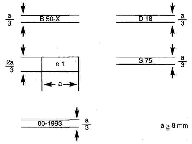
The coupling device with the EEC approval marking illustrated above is a non-standard coupling head of Class B 50-X having a D value of 18 kN and a maximum permitted static vertical bearing load of 75 kg, for which EEC component type-approval was granted in the Federal Republic of Germany (e 1) under the number 1993. The first two digits 00 indicate that this component was approved according to the original form of this Directive.
(g) Specimen EEC approval marking for a drawbar

The coupling device with the EEC approval marking illustrated above is a drawbar for a centre-axle trailer of Class E with a maximum permitted D value of 109 kN, a maximum permitted static vertical bearing load of 1 000 kg and a maximum permitted V-value of 50 kN, for which EEC component type approval was granted in the Federal Republic of Germany (e 1) under the number 0013. The first two digits 00 indicate that this component was approved according to the original form of this Directive.
ANNEX III
INFORMATION DOCUMENT No ...
relating to the EEC type-approval as a component of mechanical coupling devices for motor vehicles and their trailers (94/20/EC)
The following information, if applicable, must be supplied in triplicate and include a list of contents. Any drawings must be supplied in appropriate scale and in sufficient detail on size A4 or on a folder of A4 format. Photographs, if any, must show sufficient detail.
If the systems, components of separate technical units have electronic controls, information, concerning their performance must be supplied.

ANNEX IV


Appendix I
to EEC type-approval certificate No ... concerning the component type-approval of mechanical coupling devices with regard to Directive 94/20/EC

ANNEX V
Requirements for mechanical coupling devices
1. COUPLING BALLS AND TOWING BRACKETS
The requirements stated in 1.1 to 1.4 are applicable to all coupling balls and towing brackets of Class A. Section 1.5 lists additional requirements which must be fulfilled by standard coupling balls 50 and flange type towing brackets.
1.1. Coupling balls of Class A must conform to Figure 2 in shape and dimensions.
1.2. The shape and the dimensions of the towing brackets have to meet the requirements of the vehicle manufacturer concerning the attachment points and additional mounting devices, if necessary.
1.3. In the case of removable coupling balls the point of connection and their locking must be designed for positive mechanical engagement.
1.4. Coupling balls and towing devices must be able to satisfy the tests laid down in Annex VI, Section 4.1.

1.5. Special requirements for standard coupling balls and flange type towing brackets of Classes A 50-1, A 50-2 and A 50-3.
|
1.5.1. |
Dimensions of Class A 50-1 coupling balls and flange type towing brackets must be as given in Figure 3 and Table 1. The clearance space for coupling balls prescribed in Annex VII, Figure 30 must be respected. |
|
1.5.2. |
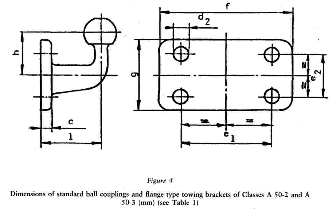
Dimensions of Class A 50-2 and Class A 50-3 coupling balls and flange type towing brackets must be as given in Figure 4 and Table 1. The clearance space for coupling balls prescribed in Annex VII, Figure 30 must be respected. |
|
1.5.3. |
Coupling balls and flange type towing brackets of the Classes A 50-1, A 50-2 and A 50-3 must be suitable and tested for the characteristic values given in Table 2.
TABLE 1 Dimensions of standard ball couplings and flange type towing rackets (mm) (see Figures 3 and 4)
TABLE 2 Characteristic values for standard ball couplings and flange type towing brackets
|

2. COUPLING HEADS
|
2.1. |
Coupling heads of Class B 50 must be designed so that they can be used safely with the coupling balls described in Section 1 of this Annex and thereby retain the prescribed characteristics. Coupling heads must be designed in such a way that safe coupling is ensured, also taking into account the wear of the coupling devices. |
|
2.2. |
Coupling heads must be able to satisfy the tests laid down in Annex VI, Section 4.2. |
|
2.3. |
Any additional device (e. g. braking, stabilizer, etc.) shall not have any adverse effect on the mechanical connection. |
|
2.4. |
Horizontal rotation of the coupling head at least 90o to either side of the centreline of the coupling ball and mounting described in Section 1 of this Annex when not attached to the vehicle must be possible. Simultaneously there must be an angle of free vertical movement 20o above and below the horizontal. Also, in conjunction with the horizontal angel of rotation of 90o it must be possible for there to be 25o of roll in both directions about the horizontal axis. The following combinations of motions must be possible:
at all angles of horizontal rotation. |
3. DRAWBAR COUPLINGS
The requirements of Sections 3.1 to 3.8 are applicable to all drawbar couplings of Class C 50. Section 3.9 lists the additional requirements which must be fulfilled by standard drawbar couplings of Classes C 50-1 to C 50-6.
3.1. Load requirements
All drawbar couplings shall be able to satisfy the tests stated in Annex VI, Section 4.3.
3.2. Suitable drawbar eyes
Class C 50 drawbar couplings shall be compatible with all Class D 50 drawbar eyes and coupling with the specified characteristics.
3.3. Automatic operation
Drawbar couplings must be automatic in operation (see Annex I, Section 2.1.17).
3.4. Jaw
Class C 50 drawbar couplings must have a jaw which is designed such that the appropriate drawbar eyes is guided into the coupling.
If the jaw, or a part supporting the jaw, can pivot about the vertical axis, it must establish itself automatically in the normal position and, with the coupling pin open, be effectively restrained in this position to give satisfactory guidance for the drawbar eye during the coupling procedure.
If the jaw, or a part supporting the jaw, can pivot about the transverse axis, the joint providing the rotation capability must be restrained in its normal position by a locking torque. This torque must be sufficient to prevent a force of 200 N acting vertically upwards on the top of the jaw producing any deflection of the joint from its normal position. It must be possible to bring the jaw to its normal position manually. A jaw that pivots about the transverse axis is only approved for vertical bearing loads S of up to 50 kg and a V-value of up to 5 kN.
If the jaw, or a part supporting the jaw, is pivoted about the longitudinal axis, the rotation must be restrained by a locking torque of at least 100 Nm.
The minimum required size of the jaw depends on the D value of the coupling:
|
|
D-value |
≤ 18 kN: |
width 150 mm, height 100 mm |
|
18 kN < |
D-value |
≤ 25 kN: |
width 280 mm, height 170 mm |
|
25 kN < |
D-value: |
|
width 360 mm, height 200 mm |
The external corners of the jaw may be radiused.
Smaller jaws are permitted for Class C 50-X drawbar coupling if their use is restricted to centre-axle trailers up to 3,5 tonnes maximum permissible mass or if the use of a jaw from the above table is impossible due to technical reasons and if, furthermore, there are special circumstances such as visual aids for ensuring safe execution of the automatic coupling procedure and if the field of application is restricted in the approval according to Annex III.
3.5. Minimum freedom of movement of the coupled drawbar eye
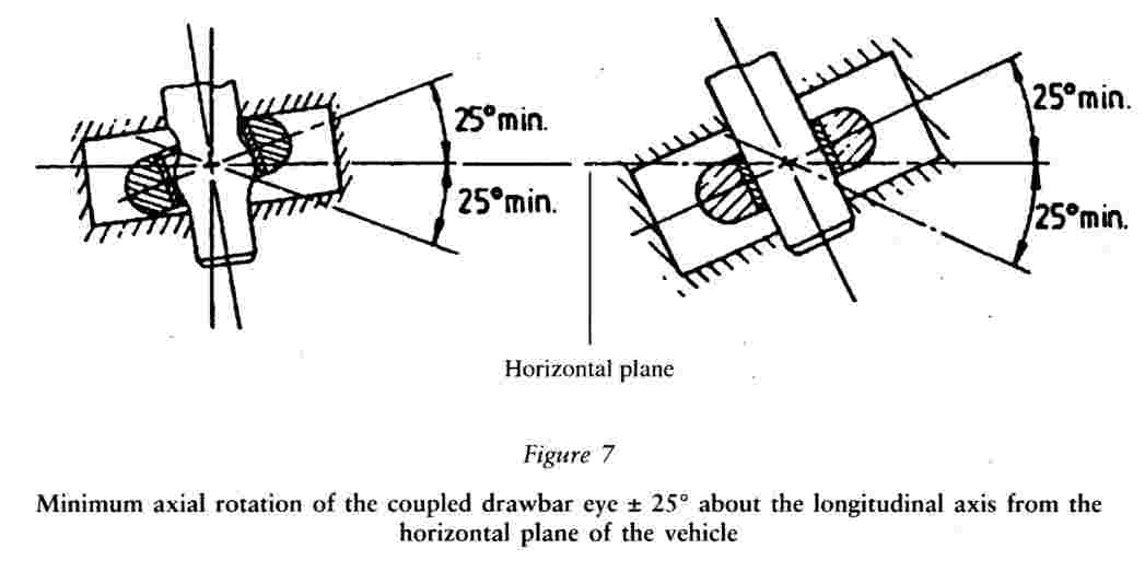
The coupled drawbar eye must be able to rotate horizontally ± 90o about the vertical axis from the longitudinal axis of the vehicle (see Figure 5). The coupled drawbar eye must be able to rotate vertically ± 20o about the transverse axis from the horizontal plane of the vehicle (see Figure 6). If the motion is provided by a special joint (only on Class C 50-X drawbar couplings) the field of application given in the approval according to Annex III must be restricted to the cases stated in Annex VII, Section 2.3.7. It must be possible for the coupled drawbar eye to be rotated axially ± 25o about the longitudinal axis from the horizontal plane of the vehicle (see Figure 7).
The stated angles of rotation are applicable to drawbar couplings not attached to the vehicle.
3.6. Minimum angle for coupling-up and uncoupling
Coupling and uncoupling of the drawbar eye must also be possible when the longitudinal axis of the drawbar eye in relation to the centreline of the jaw:
|
3.6.1. |
is rotated 50o horizontally to right or left; |
|
3.6.2. |
is rotated 6o vertically up or down; |
|
3.6.3. |
is rotated 6o axially to right or left. |
3.7. Locking to prevent inadvertent uncoupling
In the closed position the coupling pin must be secured by two positive mechanical securing devices each of which must remain effective should the other fail.
The closed and secured position of the coupling must be clearly indicated externally by a mechanical device. It must be possible to verify the position of the indicator by feel, e. g. in the dark.
The mechanical device must indicate the engagement of both locking devices (an AND condition).
However, it is sufficient for the engagement of only one locking device to be indicated if, in this situation, engagement of the second locking device is an inherent feature of the design.
3.8. Hand levers
Hand levers must be of a design suitable for easy use with the end rounded off. The coupling must have no sharp edges or points of possible pinching near the hand lever which could result in injury during operation of the coupling. The force needed to release the coupling, measured without the drawbar eye, must not exceed 250 N perpendicular to the hand lever along the line of operation.
3.9. Special requirements for standard drawbar couplings of Class C 50-1 to C 50-6.
|
3.9.1. |
The swivel motion of the drawbar eye about the transverse axis must be achieved through the spherical shape of the coupling pin (and not by means of a joint, see Figure 6). |
|
3.9.2. |
Tensile and compressive shock loads along the longitudinal axis due to the clearance between the coupling pin and the drawbar eye must be attenuated by spring and/or damping devices (except C 50-1). |
|
3.9.3. |
The dimensions given in Figure 8 and Table 3 must be adhered to. |
|
3.9.4. |
The couplings must be suitable and tested for the characteristic values given in Table 4. |
|
3.9.5. |
The coupling must be opened by means of a hand lever at the coupling (no remote control).
TABLE 3 Dimensions of standard drawbar couplings (mm) (see Figure 8)
TABLE 4 Characteristic values for standard drawbar couplings:
|
||||||||||||||||||||||||||||||||||||||||||||||||||||||||||||||||||||||||||||||||||||||||||||||||||||||||||||||||||||||||||||||||||||||||||||||||||||||||||||||||||||||||


4. DRAWBAR EYES
The requirements stated in Section 4.1 are applicable to drawbar eyes of Class D 50.
Sections 4.2 to 4.5 list the additional requirements which must be fulfilled by standard drawbar eyes.
4.1. General requirements for drawbar eyes
All drawbar eyes shall be able to satisfy the test stated in Annex VI, Section 4.4.
Class D 50 drawbar eyes are intended for use with C 50 drawbar couplings. Drawbar eyes must not be able to rotate axially (because the respective couplings can rotate).
If Class D 50 drawbar eyes are fitted with sleeves, they shall comply with the dimensions shown in Figure 12 (except class D 50-C) or Figure 13.
The sleeves must not be welded into the drawbar eyes.
Class D 50 drawbar eyes must have the dimensions illustrated in Figure 9 (if not stated otherwise in Section 4.2, 4.3 or 4.4). The form of shank for drawbar eyes of Class D 50-X is not specified, but in a distance of 210 mm from the centre of the eye the height ‘h’ and the width ‘b’ must be within the limits given in Table 6.
4.2. Special requirements for drawbar eyes of Class D 50-A
Drawbar eyes of class D 50-A must have the dimensions illustrated in Figure 9.
4.3. Special requirements for drawbar eyes of Class D 50-B
Class D 50-B drawbar eyes must have the dimensions illustrated in Figure 10.
4.4. Special requirements for drawbar eyes of Class D 50-C
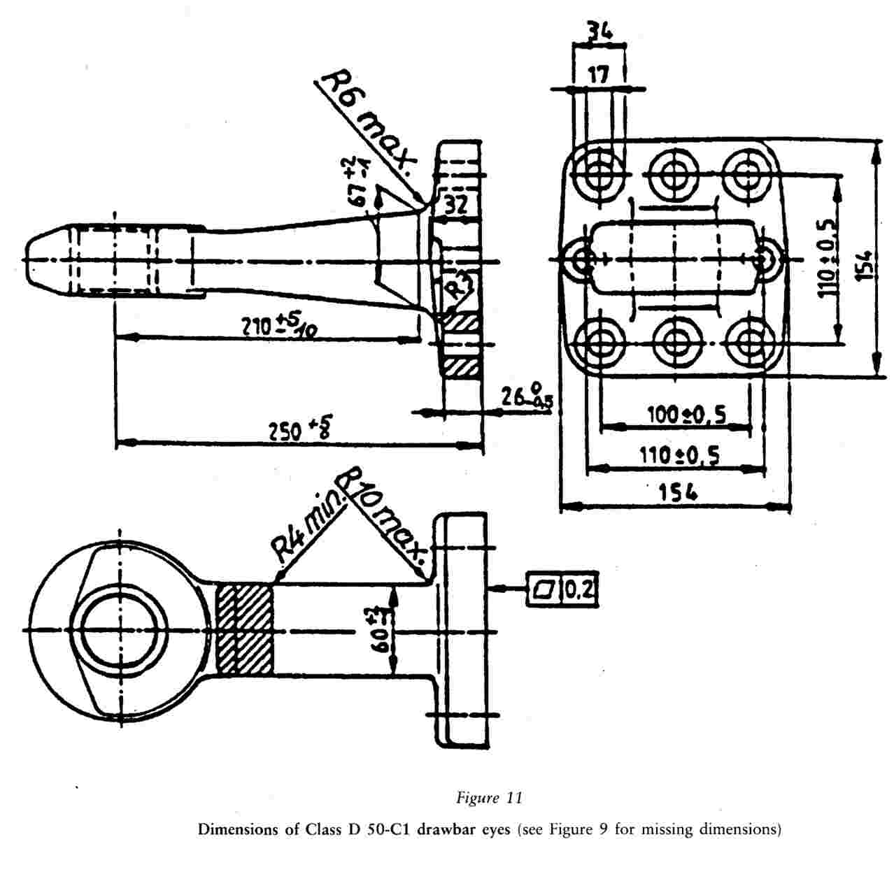
Class D 50-C drawbar eyes must have the dimensions illustrated in Figure 11.
Class D 50-C drawbar eyes must be fitted with the sleeves illustrated in Figure 13.
4.5. Load values for standard drawbar eyes
The standard drawbar eyes and their means of attachment must be suitable and tested for the load values stated in Table 5.
TABLE 5
Characteristic values for standard drawbar eyes
|
D |
= |
maximum D value (kN) |
|
Dc |
= |
maximum D value (kN) for centre-axle trailers |
|
S |
= |
maximum static vertical bearing load (kg) |
|
V |
= |
V-value (kN) |
|
Class |
D |
Dc |
S |
V |
|
D 50-A |
130 |
90 |
1 000 |
30 |
|
D 50-B |
130 |
90 |
1 000 |
25 |
|
D 50-C |
190 |
120 |
1 000 |
50 |
TABLE 6
Dimensions for drawbar eyes D 50-A and D 50-X, (see Figure 9)
|
Class |
h (mm) |
b (mm) |
|
D 50-A |
65+2 -1 |
60+2 -1 |
|
D 50-X |
67maximum |
62maximum |


5. DRAWBARS
5.1. Drawbars of Class E must be able to satisfy the tests described in Annex VI, Section 4.5.
5.2. In order to provide a connection to the towing vehicle, the drawbars can be fitted either with coupling heads as in Section 2 or drawbar eyes as in Section 4 of this Annex. The coupling heads and drawbar eyes can be attached by screwing, bolting or welding.
5.3. Hinged drawbars must be clear of the ground. They shall not fall below a height of 200 mm from the ground when released from the horizontal position.
5.4. Height adjusting devices for hinged drawbars
|
5.4.1. |
Hinged drawbars have to be equipped with devices for adjusting the drawbar to the height of the coupling device or jaw. These devices must be designed so that the drawbar can be adjusted by one person without tools or any other aids. |
|
5.4.2. |
Height adjusting devices must be able to adjust the drawbar eyes or ball couplings from the horizontal above the ground at least 300 mm upwards and downwards. Within this range the drawbar must be adjustable steplessly or in maximum steps of 50 mm measured at the drawbar eye or ball coupling. |
|
5.4.3. |
The height adjusting device must not interfere with easy movement of the drawbar after coupling-up. |
|
5.4.4. |
The height adjusting devices must not interfere with the action of any overrun brake. |
5.5. In the case of drawbars combined with overrun brakes the distance between the centre of the drawbar eye and the end of the free shank of the drawbar eye must not be less than 200 mm in the brake application position. With the shank of the drawbar eye fully inserted the distance must not be less than 150 mm.
5.6. Drawbars for use on centre-axle trailers must possess at least half the moment of resistance against lateral forces as against vertical forces.
6. MOUNTING FRAMES
|
6.1. |
Mounting frames shall be appropriate for the attachment of the concerned coupling device to the corresponding vehicle(s). |
|
6.2. |
Mounting frames must not be welded to the chassis, bodywork or other part of the vehicle. |
|
6.3. |
Mounting frames must be able to satisfy the tests laid down in Annex VI, Section 4.3. |
7. FIFTH WHEEL COUPLINGS AND STEERING WEDGES
The requirements of Sections 7.1 to 7.9 are applicable to all fifth wheel couplings of Class G 50.
Section 7.10 lists the additional requirements which must be fulfilled by standard coupling devices.
Steering wedges must satisfy the requirments listed in Section 7.9.
7.1. Suitable fifth wheel coupling pins.
Class G 50 fifth wheel couplings must be designed so that they can be used with Class H 50 coupling pins and provide the specified characteristics with them.
7.2. Automatic operation
Fifth wheel couplings must be automatic in operation (see Annex I, Section 2.1.17).
7.3. Guides
Fifth wheel couplings must be equipped with a guide which ensures safe and secure engagement of the coupling pin. The entry width of the guide must be at least 350 mm.
7.4. Minimum free movement of the fifth wheel coupling with the coupling pin engaged (but with the fifth wheel coupling not attached to a mounting plate or vehicle)
With the coupling pin engaged, fifth wheel couplings must permit the following minimum values of rotation of the coupling pin in the travelling position:
|
7.4.1. |
± 90o about the vertical axis (not applicable to fifth wheel couplings with positive steering) and, simultaneously, |
|
7.4.2. |
± 12o about the horizontal axis transverse to the direction of travel. This angle does not necessarily cover off-road use. |
|
7.4.3. |
Rotation about the longitudinal axis of up to ± 3o is permitted. However, on a fully oscillating fifth wheel coupling, this angle may be exceeded, providing that locking mechanism enables the restriction of the rotation up to ± 3o. |
7.5. Locking devices to prevent uncoupling of fifth wheel couplings
The locking mechanism of the coupling must secure the coupling pin two positive ways; the second locking device may operate on the first. The first locking device must operate automatically at coupling-up. If the second locking device has to be operated by hand it should only be possible to engage it after the first device has been fully engaged. If the second locking device operates automatically, the engagement of both must be indicated visually.
7.6. Operating devices
In the closed position the operating devices must be secured to prevent inadvertent operation.
7.7. Surface finish
The surfaces of the coupling plate and coupling lock must be functionally satisfactory and carefully machined, forged, cast or pressed.
7.8. Load requirements
All fifth wheel couplings must be able to satisfy the tests described in Annex VI, Section 4.6.
7.9. Steering wedges
Coupling of Class G 50-X which are unsuitable for positive steering must be marked appropriately.
|
7.9.1. |
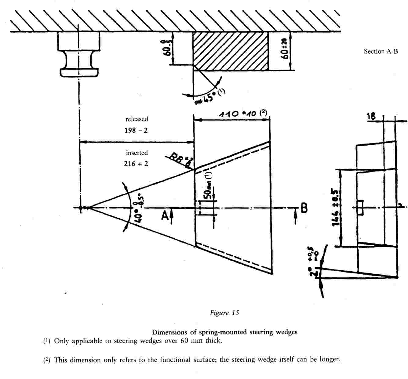
The dimensions of steering wedges for the positive steering of semi-trailers must be as in Figure 15. |
|
7.9.2 |
The steering wedge must allow safe and secure coupling-up. The steering wedge must be spring-mounted. The strength of the spring must be selected so that it is possible to couple up an unloaded semi-trailer and so that, with the semi-trailer fully loaded, the steering wedge is firmly in contact with the flanks of the coupling during travel. Uncoupling of the fifth wheel must be possible with the semi-trailer both loaded and unloaded. |
7.10. Special requirements for standard fifth wheels couplings
|
7.10.1. |
Standard fifth wheel couplings must have the dimensions indicated in Figure 14 and Table 7. |
|
7.10.2. |
Standard fifth wheel couplings must be suitable for and tested for a D-value of 150 kN and a value of U of 20 tonnes. |
|
7.10.3. |
Release must be possible by a hand lever directly at the coupling. |
|
7.10.4. |
Standard fifth wheel couplings must be suitable for the positive steering of semi-traiters by means of steering wedges (see Section 7.9). |
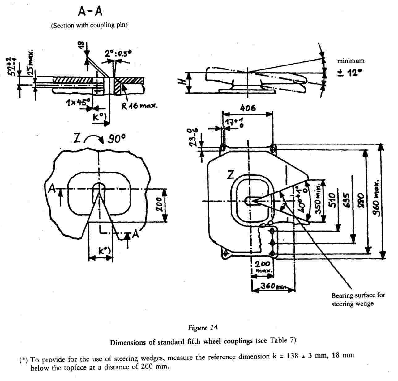
TABLE 7
Dimensions of standard fifth wheel couplings (mm) (see Figure 14)
|
|
G 50-1 |
G 50-2 |
G 50-3 |
G 50-4 |
G50-5 |
G 50-6 |
|
H |
140 to 159 |
160 to 179 |
180 to 199 |
200 to 219 |
220 to 239 |
240 to 260 |
8. FIFTH WHEEL COUPLING PINS
|
8.1. |
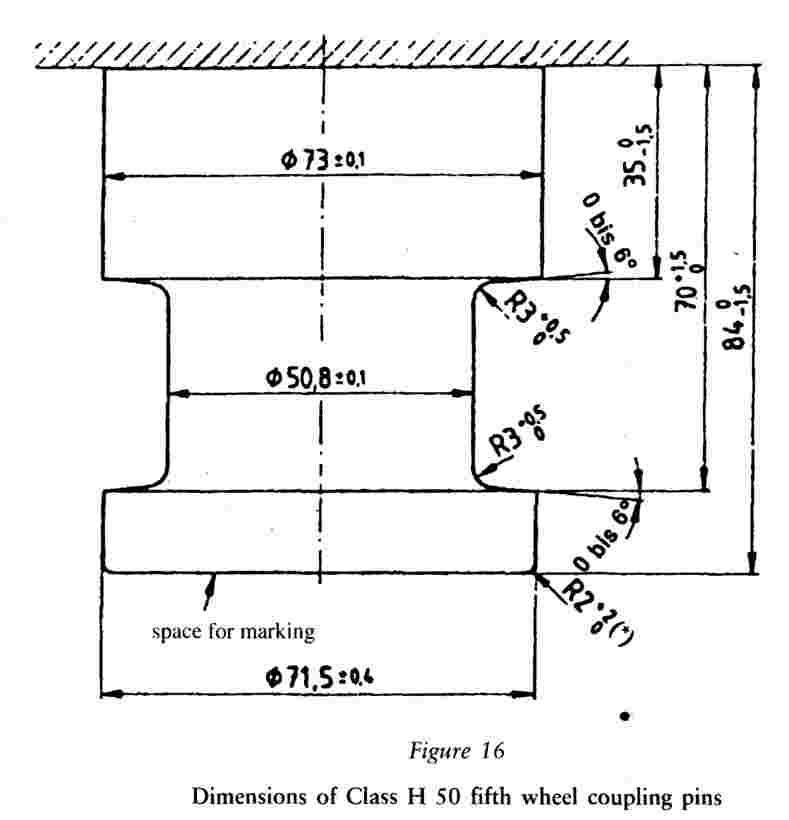
Fifth wheel coupling pins of class H 50 (ISO 337) must have the dimensions shown in Figure 16. |
|
8.2. |
The coupling pins must be able to satisfy the tests described in Annex VI, Secion 4.8. |
9. MOUNTING PLATES
|
9.1. |
Class J mounting plats for fifth wheel couplings must have a hole configuration corresponding to Figure 14 if they are intended for standard fifth wheel couplings. |
|
9.2. |
Mounting plates for standard fifth wheel couplings must be suitable for the positive steering of semi-trailers (with steering wedges). Mounting plates for non-standard fifth wheel couplings which are unsuitable for positive steering must be marked appropriately. |
|
9.3. |
Mounting plates for fifth wheel couplings must be able to satisfy the tests described in Annex VI, Section 4.7. |
10. DEVICES FOR REMOTE INDICATION AND REMOTE CONTROL
10.1. General requirements
Devices for remote indication and remote control are permitted on automatic coupling devices of Classes C 50-X and G 50-X.
Devices for remote indication and remote control must not interfere with the minimum free movement of the coupled drawbar eye or coupled semi-trailer. They must be permanently connected to the vehicle.
All the devices for remote indication or remote control fall within the scope of testing and approval of the coupling device together with all parts of the operating devices and transmission devices.
10.2. Remote indication
|
10.2.1. |
For an automatic coupling procedure, remote indication devices must indicate the closed and doubly locked position of the coupling in an optical manner according to Section 10.2.2 and/or 10.2.3. |
|
10.2.2. |
The change from the open to the closed and doubly locked position shall be indicated by a green optical signal. |
|
10.2.3. |
If the open and/or unsecured position is indicated, a red optical signal shall be used. |
|
10.2.4. |
In the case of indicating the completion of the automatic coupling procedure, the remote indicator shall ensure that the coupling pin has reached the doubly locked end position. |
|
10.2.5. |
The appearance of any fault in the remote indication system shall not indicate a closed and locked position during the coupling procedure if the end position has not been reached. |
|
10.2.6. |
The disengagement of one of the two locking devices must cause the green optical signal to extinguish and/or the red optical signal to show. |
|
10.2.7. |
The mechanical indicators directly at the coupling device must be retained. The remote indication device shall be automatically activated during every coupling procedure. |
|
10.2.8. |
In order to avoid distracting the driver during normal driving, there shall be a provision for switching off the remote indication device. |
|
10.2.9. |
The operating controls and indicators of the remote indication devices must be mounted within the driver's field of vision and be permanently and clearly identified. |
10.3. Remote control
|
10.3.1. |
If a remote control device is employed, there must also be a remote indication device as described in Section 10.2 which must also indicate the open condition of the coupling. |
|
10.3.2. |
There must be a dedicated switch (i. e. master switch, lever or valve) to enable the coupling to be opened or closed by means of the remote control device. If this master switch is not located in the driving cab it must not be in a position where it is freely accessible to unauthorized persons or it must be lockable. The actual operation of the coupling from the driving cab may only be possible when inadvertent operation has been precluded (e. g. by means of two-hand operation). It must be possible to ascertain whether opening of the coupling under remote control has been completed or not. |
|
10.3.3. |
If remote control involves the coupling being opened by external force, the condition under which the external force acts on the coupling must be indicated appropriately to the driver. This is not necessary if the external force is only operative while the remote control is operating. |
|
10.3.4. |
If the actuating device for opening the coupling under remote control is mounted externally on the vehicle it must be possible to oversee the area between the coupled vehicles, but it must not be necessary, however, to enter this area in order to operate it. |
|
10.3.5. |
Any single error in operation or the occurrence of any single fault in the system must not result in accidental opening of the coupling during normal road travel. Any faults in the system must be indicated directly or be immediately obvious at the next operation, e. g. by a malfunction. |
|
10.3.6. |
In the event of a failure of remote control it must be possible to open the coupling in at least one other way in an emergency case. If this requires the use of a tool it must be included in the vehicle's tool kit. The requirements of Annex V, Section 3.8 are not applicable to hand levers used exclusively for opening the coupling in an emergency. |
|
10.3.7. |
The operating controls and indicators for the remote control devices must be permanently and clearly identified. |
ANNEX VI
TESTING OF MECHANICAL COUPLING DEVICES
1. GENERAL TESTING REQUIREMENTS
|
1.1. |
Specimens of coupling devices must be tested; both, strength tests and function tests being performed. However the Technical Service may waive a strength test if the simple design of a component makes a theoretical check possible. The theoretical checks must ensure the same quality of results as with dynamic or static testing. In cases of doubt it is the results of dynamic testing that are overriding. The Technical Service responsible will decide on the type of tests to be employed. |
|
1.2. |
With coupling devices the strength must be verified by a dynamic test (endurance test). In certain cases some additional static tests may be necessary (see Section 4). |
|
1.3. |
The dynamic test should be performed with approximately sinusoidal load (alternating and/or pulsating) with a number of stress cycles appropriate to the material. No cracks of fractures must occur. |
|
1.4. |
Only slight permanent deformation is permitted with the static tests prescribed. The plastic deformation after releasing must not be more than 10 % of the maximum deformation. |
|
1.5. |
The loading assumptions in the dynamic tests are based on the horizontal force component in the longitudinal axis of the vehicle and the vertical force component. Horizontal force components transverse to the longitudinal axis of the vehicle, and moments, are not taken into account provided they are of only minor significance. If the design of the coupling device or its attachment to the vehicle or the attachment of additional systems (as stabilizers, short coupling systems, etc.) generates additional forces or moments additional tests may be required by the Technical Service. The horizontal force component in the longitudinal axis of the vehicle is represented by a theoretically determined reference force, the D value as defined in Annex 1, Section 2.1.18. The vertical force component, where applicable, is represented by the static vertical bearing load S at the point of coupling and the assumed vertical load V, defined in Annex I, Section 2.1.19 or by the static vertical bearing load U in case of fifth wheel couplings. |
|
1.6. |
The characteristic values D, S, V and U on which the tests are based, must be taken from the manufacturer's application for the granting of EEC type-approval. |
2. TEST PROCEDURES
|
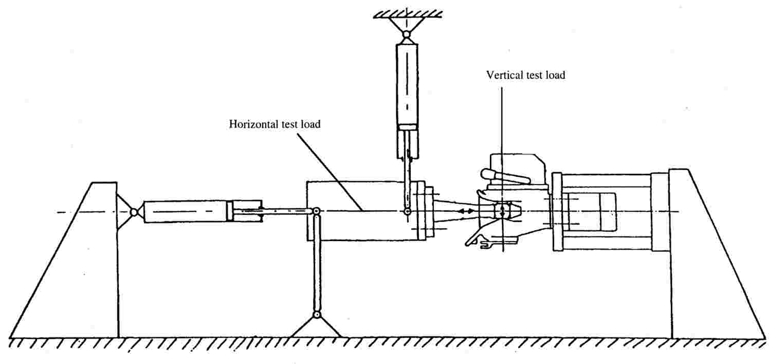
2.1. |
For the dynamic tests and static tests the specimen must be placed in a suitable rig with a suitable means of force application so that it is not subjected to any additional forces or moments apart from the specified test force. In the case of alternating tests the direction of force application must not deviate by more than +1o from the specified direction. In the case of pulsating and static tests the angle must be set for top force. This will normally require a joint at the point of force application (i. e. the point of coupling) and a second joint an adequate distance away. |
|
2.2. |
The test frequency must not exceed 35 Hz. The selected frequency shall be well separated from resonance frequencies of the test set-up including the tested device. With asynchronous testing the frequencies of the two force components must be approximately 1 % to a maximum of 3 % apart. For coupling devices made of steel the number of stress cycles is 2 x 10⁶. For devices made of other materials than steel a higher number of cycles may be necessary. The dye-penetration method of crack testing or an equivalent method must be employed. |
|
2.3. |
With alternating test forces (components) the mean force is zero. With pulsating tests the test force is equal to the top force; the bottom force may be up to 5 % of the top force unless stated otherwise in the specific testing requirements. |
|
2.4. |
With static tests other than the special tests required by paragraph 4.2.3, the test force must be applied smoothly and quickly and be maintained for at least 60 seconds. |
|
2.5. |
The coupling devices on test should normally be mounted as rigidly as possible on a test rig in the actual position in which they will be used on the vehicle. The fixing devices should be those specified by the manufacturer or applicant and should be those intended for its attachment to the vehicle and/or shall have identical mechanical characteristics. |
|
2.6. |
Preferably, couplings have to be tested in original condition as being foreseen for the use on the road. At the discretion of the manufacturer and in agreement with the Technical Service flexible components may be neutralized if this is necessary for the test procedure and if there is no concern about unrealistic influence to the test result. Flexible components being apparently overheated due to this accelerated test procedure may be replaced during the test. The test loads may be applied by means of special slack-free devices. |
3. SYMBOLS AND DEFINITIONS IN ANNEX VI
|
Av |
= |
maximum permitted axle load of the steered axle in t |
|
C |
= |
mass of centre axle trailer in t (as Annex I, Section 2.1.18) |
|
D |
= |
D value in kN (Annex I, Section 2.1.18) |
|
R |
= |
mass of full trailer in t (Annex I, Section 2.1.18) |
|
T |
= |
mass of towing vehicle in t (Annex I, Section 2.1.18) |
|
FA |
= |
static lifting force in kN |
|
Fh |
= |
horizontal component of test force in longitudinal axis of vehicle in kN |
|
Fs |
= |
vertical component of test force in kN |
|
Fq |
= |
horizontal component of test force transverse to longitudinal axis of vehicle in kN |
|
Fhq res |
= |
resultant test force of Fh and Fs in kN |
|
Fhq res |
= |
resultant test force of Fh and Fq in kN |
|
S |
= |
static vertical load in kg |
|
U |
= |
fifth wheel imposed vertical load in t |
|
V |
= |
V-value in kN (Annex I, Section 2.1.19) |
|
a |
= |
equivalent vertical acceleration factor in the coupling point of centre-axle trailers depending on the kind of suspension on the rear axle(s) of the towing vehicle |
|
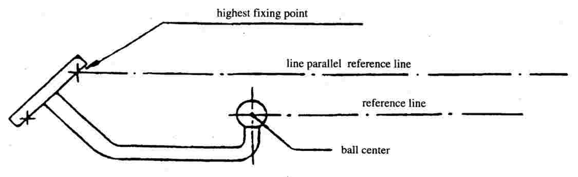
e |
= |
longitudinal distance between the coupling point of coupling balls which can be dismantled and the vertical plane of the fixing points (see Figures 22 to 25) in mm |
|
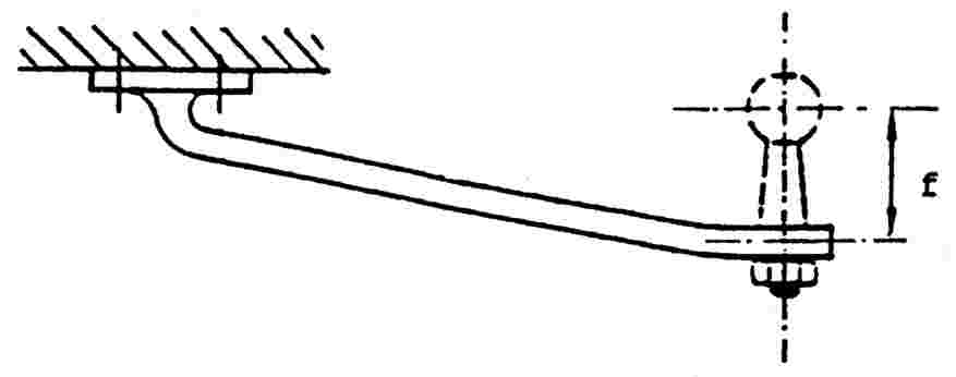
f |
= |
vertical distance between the coupling point of coupling balls which can be dismantled and the horizontal plane of the fixing points (see Figures 21 to 25) in mm |
|
g |
= |
acceleration due to gravity, assumed as 9,81 m/s2 |
|
l |
= |
theoretical drawbar length between the centre of the drawbar eye and the centre of the axle assembly in metres |
|
n |
= |
distance between drawbar eye and centre line of the steered axle in mm |
|
r |
= |
scrub radius in mm |
|
s |
= |
track in mm |
|
x |
= |
length of the loading area of a centre axle trailer in metres |
Subscripts:
|
O |
= |
top force |
|
U |
= |
bottom force |
|
w |
= |
alternating |
|
h |
= |
horizontal |
|
s |
= |
vertical |
4. SPECIFIC TESTING REQUIREMENTS
4.1. Coupling balls and towing brackets
|
4.1.1. |
The mechanical coupling devices of coupling balls may be of the following types:
|
|
4.1.2. |
The basic test is an endurance test with an alternating test force. The test specimen is the coupling ball, the ball neck and the mountings necessary for attaching to the vehicle. The coupling ball and towing brackets must be rigidly mounted to a test rig, capable of producing alternating forces, in the actual position in which it is intended for use. |
|
4.1.3. |
The positions of the fixing points for attaching the coupling ball and towing brackets are specified by the vehicle manufacturer (see Annex VII, Section 1.2). |
|
4.1.4. |
The devices submitted to the test shall be provided with all design details which may have an influence on the strength criteria (for example electrical socket plate, any marking, etc.). The test periphery ends at the anchorage points or fitting points. The geometric location of the coupling ball and the fixing points of the coupling device related to the reference line shall be provided by the vehicle manufacturer and shall be shown in the test report. All relative positions of the anchorage points with respect to the reference line, for which the towing vehicle manufacturer shall provide all the necessary information to the towing device manufacturer, shall be repeated on the test bed. |
|
4.1.5. |
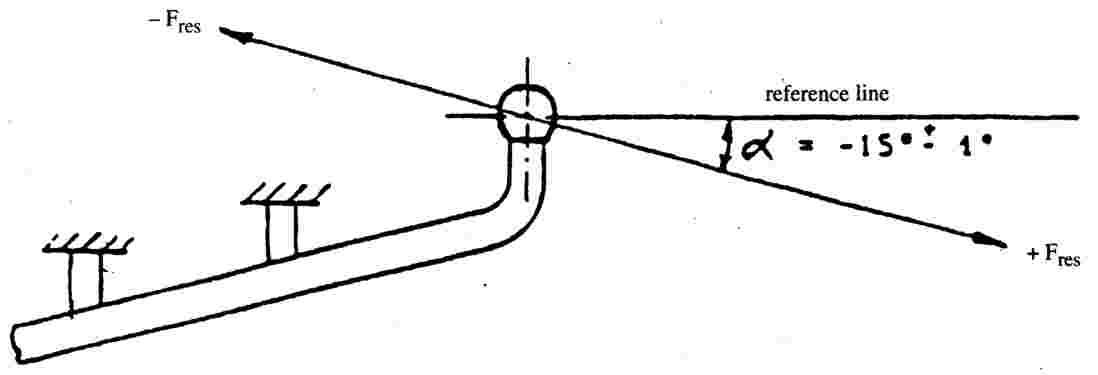
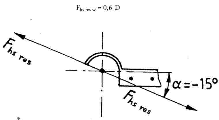
The assembly mounted on the test bed shall be subjected to a test on an alternating stress tensible testing machine (for example on a resonance pulser). The test load shall be an alternating force and must be applied to the coupling ball at an angle of 15o ± 1o as shown in Figure 17 and/or Figure 18. If the ball centre is above that line parallel to the reference line as shown in Figure 19 which contains the highest of the nearest fixing points, the test has to be carried out with an anlge α = -15o ± 1o (see Figure 17). If the ball centre is below that line parallel to the reference line as shown in Figure 19 which contains the highest of the nearest fixing points, the test has to be carried out with an angle α = + 15o ± 1o (see Figure 18). This angle is chosen in order to take account of the vertical static and dynamic load. This test method is only applicable to a permitted static load of not more than
If a static load above 120 · D is requested, the test angle should be increased to 20o. The dynamic test must be performed with the following test force: Fhs res = ± 0,6 D
|


|
4.1.6. |
The test procedure is applicable to the different types of coupling devices (see Section 4.1.1) as follows:
|


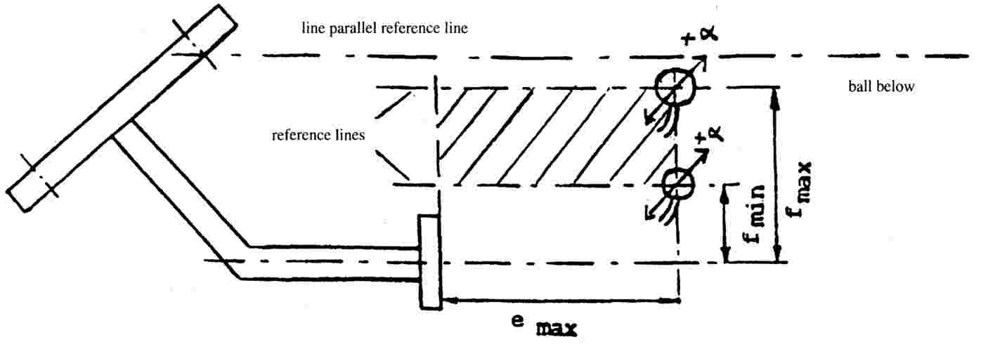
4.1.6.3. Coupling devices with variable dimensions e and f for demountable and interchangeable coupling balls.
|
4.1.6.3.1. |
The strength tests for such towing brackets (shown in Figure 25) shall be carried out to the requirements of Section 4.1.5. |
|
4.1.6.3.2. |
If a worst case configuration can be defined by agreement between the manufacturer and the Technical Service, the testing of this one configuration alone shall be sufficient. Otherwise, several ball positions shall be tested in a simplified test programme according to Section 4.1.6.3.3. |
|
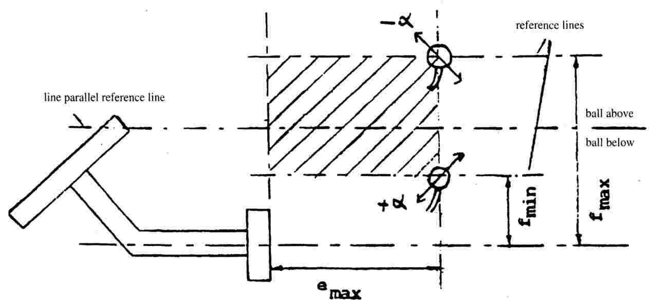
4.1.6.3.3. |
In a simplified test programme, the value for f shall be between a defined value of fmin and a value of fmax which does not exceed 100 mm. The ball shall be at a distance (emax) of 130 mm from the support. To cover all possible positions of the ball, in the field given by the horizontal distance from the mounting surface and the vertical range of f (fmin to fmax), two devices are to be tested:
If the field of possible ball positions is divided by the line parallel reference line (see Figure 25c), the test angles are:
|

4.2. COUPLING HEADS
|
4.2.1. |
The basic test is an endurance test with an alternating test force and a static test (lifting test) on each test specimen. |
|
4.2.2. |
The dynamic test must be performed with a Class A coupling ball of appropriate strength. On the test rig the ball coupling and coupling ball must be arranged as instructed by the manufacturer and in a way corresponding to their attachment in a vehicle. There should be no possibility of extra forces in addition to the test force acting on the specimen. The test force must be applied along a line passing through the centre of the ball and inclined downwards to the rear at 15o (see Figure 26). An endurance test must be performed on a test specimen with the following test force: Fhs res w = 0,6 D
|
|
4.2.3. |
A static lifting test must also be performed. The coupling ball used for the test must have a diameter of
in order to represent a worn coupling ball. The lifting force FA must be increased smoothly and quickly to a value of
and be held for 10 seconds (see Figure 27). The coupling head shall not separate from the ball or exhibit any permanent distortion which could have an adverse effect on its functional capability.
|


4.3. Drawbar couplings and draw beams
4.3.1. An endurance test must be performed on a test specimen. The coupling device must be equipped with all the fixings needed to attach it to the vehicle. Any intermediate devices fitted between the drawbar couplings and the vehicle frame (i. e. drawbeams) must be tested with the same forces as the coupling. When testing drawbeams intended for standard drawbar couplings, the vertical load shall be applied at a longitudinal distance from the vertical plane of the fixing points that is equal to the position of the corresponding standard coupling.
4.3.2. Drawbar couplings for hinged drawbars (S=0)
The dynamic tests must be performed with a horizontal alternating force of Fhw = 0,6 D acting in a line parallel to the ground and in the longitudinal median plane of the towing vehicle passing through the centre of the coupling pin.
4.3.3. Drawbar couplings for use with centre-axle trailers (S > 0).
4.3.3.1.
Drawbar couplings for use with centre-axle trailers up to and including a mass of 3,5 tonnes must be tested in the same way as coupling balls and towing brackets described in Section 4.1 of this Annex.
4.3.3.2.
The test loads are applied to the specimen in the horizontal and vertical directions in an asynchronous endurance test. The horizontal line of action must be parallel to the ground in the longitudinal median plane of the towing vehicle and pass through the centre of the coupling pin. The vertical line of action must be perpendicular to the ground in the longitudinal median plane of the towing vehicle and pass through the centre of the coupling pin (see Figure 28).
The fixing arrangements for the drawbar coupling and the drawbar eye on the test bed shall be those intended for its attachment to the vehicle in accordance with the manufacturer's fitting instructions.
The following test loads shall be applied to the coupling point
|
Test load |
Mean value (kN) |
Amplitude (kN) |
|
Horizontal load |
0 |
± 0,6 D |
|
Vertical load |
|
± 0,6 V |

The test force is the geometrical sum of the vertical and the horizontal components. This can be achieved by the test bed configuration shown in Figure 28. The vertical and the horizontal components shall be sinusoidal in shape and shall be applied asynchronously, where the difference of their frequencies shall be between 1 and 3 %, so that resulting test forces in all directions are created.
4.3.4. Static test on coupling pin locking device
With drawbar couplings it is also necessary to test the closure and any locking devices by means of a static force of 0,25 D acting in the direction of opening. The test must not cause the closure to open and it must not cause any damage. A test force of 0,1 D is sufficient in the case of cylindrical coupling pins.
4.4. Drawbar eyes
|
4.4.1. |
Drawbar eyes must be subjected to the same dynamic testing as drawbar couplings. Drawbar eyes used solely for trailers having hinged drawbars allowing free vertical movement must be subjected to an alternating load as described in Section 4.3.2. Drawbar eyes also intended for use on centre-axle trailers must be tested in the same way as ball couplings (Section 4.2) for trailer masses C up to and including 3,5 tonnes and in the same way as drawbar couplings (Section 4.3.3.2) for centre-axle trailer with a mass C exceeding 3,5 tonnes. |
|
4.4.2. |
The testing of drawbar eyes must be conducted in such a manner that the alternating load also acts on the parts used for attaching the drawbar eye to the drawbar. All flexible intermediate components must be clamped. |
4.5. Drawbars
|
4.5.1. |
Drawbars shall be tested in the same way as drawbar eyes (see Section 4.4). The technical service may waive an endurance test if the simple design of a component makes a theoretical check of its strength possible. The design loads for the theoretical verification of the drawbar of centre-axle trailers with a mass C of up to and including 3,5 tonnes shall be taken from ISO 7641/1 (1983). The design loads for the theoretical verification of drawbars for centre-axle trailers having a mass C over 3,5 tonnes must be calculated as follows:
where the force amplitude V is that given in Annex I, Section 2.1.19. The permissible stresses based on the design load for trailers having a total mass C over 3,5 tonnes shall be in accordance with paragraph 5.3 of ISO 7641/1. For bent drawbars (e. g. swan neck) and for drawbars of full trailers, the horizontal force component Fhp = 1,0 × D shall be taken into consideration. |

|
4.5.2. |
For drawbars for full trailers with free movement in the vertical plane, in addition to the endurance test or theorectical verification of strength, the resistance to buckling must be verified either by a theoretical calculation with a design load of 3,0 D or by a buckling test with a design load of 3,0 × D. The permissible stresses in case of calculation shall be in accordance with paragraph 5.3 of ISO 7641/1. |
|
4.5.3. |
In the case of steered axles, the resistance to bending must be verified by theoretical calculations or by a bending test. A horizontal lateral static force must be applied in the centre of the coupling point. The magnitude of this force must be chosen so that a moment of 0,6 x Av × g (kNm) is exerted about the front axle centre. The permissible stresses shall be in accordance with paragraph 5.3 of ISO 7641/1. |
4.6. Fifth wheel couplings
4.6.1. The basic strength tests are a dynamic test and a static test (lifting test). Fifth wheel couplings intended for the positive steering of semi-trailers must be subject to an additional static test (bending test). For the purpose of the tests the fifth wheel coupling must be equipped with all the fixings needed to attach it to the vehicle. The method of mounting must be indentical to that employed subsequently on the vehicle itself.
4.6.2. Static tests
|
4.6.2.1. |
Standard fifth wheel couplings designed for a steering wedge or similar device for the positive steering of semi-trailers (see Annex V, Section 7.9) must be tested for adequate strength by means of a static bending test within the working range of the steering device with the simultaneous application of fifth wheel load. The maximum permitted fifth wheel load U must be applied vertically on the coupling in its operating position by means of a rigid plate of sufficient size to cover the coupling completely. The resultant of the applied load must pass through the centre of the horizontal joint of the fifth wheel coupling. Simultaneously, a horizontal lateral force, representing the force needed for positive steering of the semi-trailer, must be applied to the flanks of the guide for the coupling pin. The magnitude of this force and the direction in which it acts must be chosen so that a moment of 0,75 m X D is exerted about the centre of the coupling pin. The moment should be applied by means of a force acting on a lever arm 0,5 m long. Permanent (plastic) distortion up to 0,5 % of all nominal dimensions is permitted. There must be no cracking. |
|
4.6.2.2. |
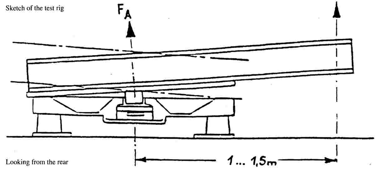
A static lifting test must be performed on all fifth wheel couplings. Up to a lifting force of FA = g · U there must be no major permanent bending of the coupling plate over more than 0,2 % of its width. In the case of Class G 50 standard fifth wheel couplings and comparable couplings for the same coupling pin diameter there must be no separation of the coupling pin from the coupling with a lifting force of FA = g · 2,5 · U. The force should be applied by means of a lever bearing on the coupling plate at one end and being raised at the other end at a distance of 1,0 to 1,5 m from the centre of the coupling pin (see Figure 29). The lever arm must be at 90o to the direction of entry of the coupling pin into the coupling. If the worst case is obvious, this worst case has to be tested. If the worst case is not easy to determine, the technical service shall decide which side to test. No second test shall be required.
|
4.6.3. Dynamcic test
The fifth wheel coupling must be subjected to alternating stress on a test rig (asynchronous dynamic test) with horizontal alternating and vertical pulsating forces acting simultaneously.
|
4.6.3.1. |
In the case of fifth wheel couplings not intended for the positive steering of semi-trailers the following forces must be used:
These two forces must be applied in the longitudinal median plane of the vehicle with FsO,U passing through the centre of the joint of the coupling. The vertical force FsO,U alternates between the limits + 1,2 · U and + 0,4 · U and the horizontal force between + 0,6 · D and - 0,6 · D. |
|
4.6.3.2. |
In the case of fifth wheel couplings intended for the positive steering of semi-trailers the following forces must be used:
The lines of action of the forces are shown in Section 4.6.3.1. |
|
4.6.3.3. |
For the dynamic test of fifth wheel couplings, a suitable lubricating material shall be placed between the coupling plate and the trailer plate so that a maxium friction coefficient of μ = 0,15 is assured. |
4.7. Mounting plates for fifth wheel couplings
The dynamic test for fifth wheel couplings described in Section 4.6.3 and the static tests described in Section 4.6.2 must be applied appropriately to mounting plates. With mounting plates it is sufficient to perform the lifting test on one side only. The test must be based on the maximum assigned installation height for the coupling, the maximum assigned width and the miminum assigned length of the mounting plate design. It is not necessary to carry out this test if the mounting plate is narrower and/or longer and the total height lower, but otherwise identical to a design which has already undergone this test.
4.8. Fifth wheel coupling pins of semi-trailers
|
4.8.1. |
A dynamic test with alternating stress must be performed on a specimen on a test rig. The testing of the coupling pin must not be combined with the testing of the fifth wheel coupling. The test must be conducted so that the load is also applied to the fixings needed for attaching the coupling pin to the semi-trailer. |
|
4.8.2. |
A dynamic test with a horizontal load of Fhw = ± 0,6 · D must be applied to the coupling pin in the operating position. The line of action of the force must pass through the centre of the smallest diameter of the cylindrical part of the coupling pin having a diameter of 50,8 mm for Class H 50 (see Annex V, Figure 16). |
ANNEX VII
REQUIREMENTS RELATING TO THE TYPE-APPROVAL OF THE VEHICLE TYPE WITH REGARD TO THE OPTIONAL ATTACHMENT OF MECHANICAL COUPLING DEVICES TO THIS VEHICLE.
1. GENERAL REQUIREMENTS
|
1.1. |
The vehicle manufacturer shall state which types and classes of coupling devices may be fitted to the vehicle type giving the values of D, V (1), S or U (if applicable) which are based on the construction of the vehicle type in combination with the type(s) of the coupling device(s) intended to be used. The characteristics D, V, S or U of the coupling devices approved in accordance with this Directive shall be equal or greater than the characteristics given for the combination concerned. |
|
1.2. |
The coupling device shall be attached to the vehicle type according to the installation instructions, given by the vehicle manufacturer in agreement with the coupling manufacturer and the Technical Service. The vehicle manufacturer shall state the appropriate attachment points for the coupling device on the vehicle type and, if necessary, mounting brackets, mounting plates, etc. to be fitted on the specific vehicle type. |
|
1.3. |
Only automatic coupling devices which allow an automatic coupling procedure on motor vehicles shall be employed for the coupling of trailers having a maximum mass of more than 3,5 tonnes. |
|
1.4. |
When mounting coupling devices of Classes B, D, E and H on trailers, a value of 32 tonnes for the maximum mass T of the towing vehicle must be taken into account for D-value calculation. If the D-value of the coupling device is not sufficient for T = 32 tonnes, the resulting restriction on the mass T of the towing vehicle or the mass of the vehicle combination must be stated in the EEC vehicle type-approval certificate of the trailer (Annex IX). |
2. SPECIAL REQUIREMENTS
2.1. Attachment of coupling balls and towing brackets
|
2.1.1. |
Coupling balls and towing brackets must be attached to a vehicle of category M1, category M2 below 3,5 tonnes and category N1 in a manner which conforms to the clearance and height dimensions given in Figure 30. This requirement shall not apply to off-road vehicles as defined in Annex II to Directive 92/53/EEC
|

|
2.1.2. |
For coupling balls and towing brackets the vehicle manufacturer must supply mounting instructions and state whether any reinforcement of the fixing area is necessary. |
|
2.1.3. |
It must also be possible to couple and uncouple ball couplings when the longitudinal axis of the ball coupling in relation to the centre line of the coupling ball and mounting:
|
|
2.1.4. |
The mounted coupling ball must not obscure the place or visibility of the rear license plate, otherwise a coupling ball which can be dismantled without special tools has to be used. |
2.2. Attachment of coupling heads
|
2.2.1. |
Class B coupling heads are permitted for trailers of the maximum mass up to and including 3,5 tonnes. With the trailer horizontal and carrying the maximum permitted axle load, coupling heads must be attached so that the coupling point of the trailer is 430 ± 35 mm above the horizontal plane on which the wheels of the trailer stand (see Figure 31). In the case of caravans and goods trailers, the horizontal position is regarded as when the floor or loading surface is horizontal. In the case of trailers without such a reference surface (e.g. boat trailers or similar) the trailer manufacturer must give an appropriate reference line defining the horizontal position. The height requirement shall apply only to trailers intended to be attached to vehicles mentioned in Section 2.1.1. |
|
2.2.2. |
It must be possible to operate the coupling heads safely within the free space of the coupling ball given in Figure 30.
|

2.3. Attachment of drawbar couplings and mounting blocks
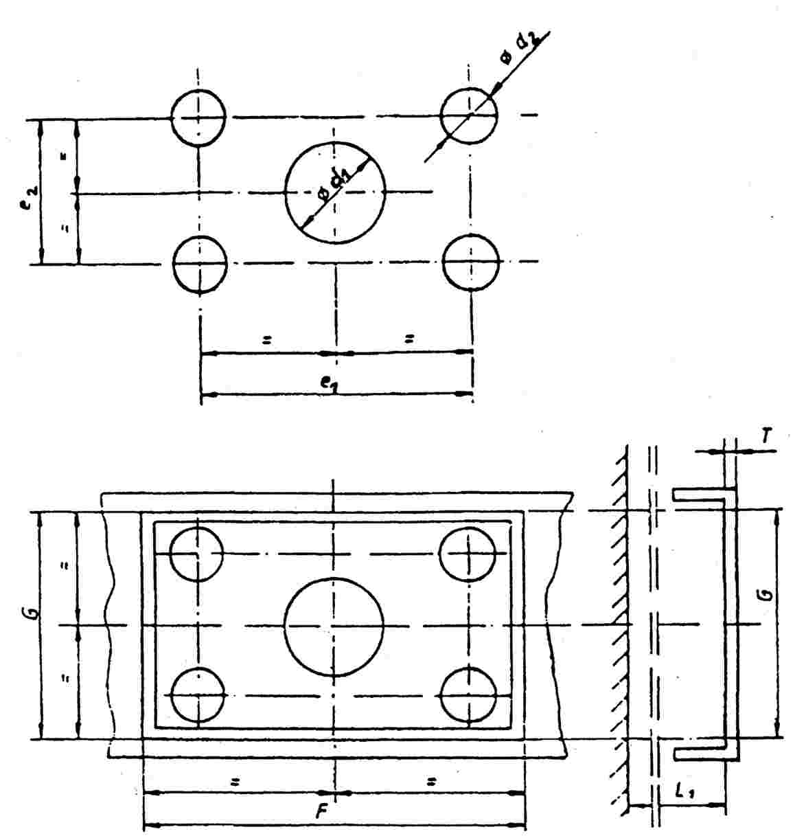
2.3.1. Mounting dimensions for standard drawbar couplings
If types of standard drawbar couplings are intended to be fitted to the vehicle type, the mounting dimensions on the vehicle given in Figure 32 and Table 8 must be met.
2.3.2. Need for remote controlled couplings
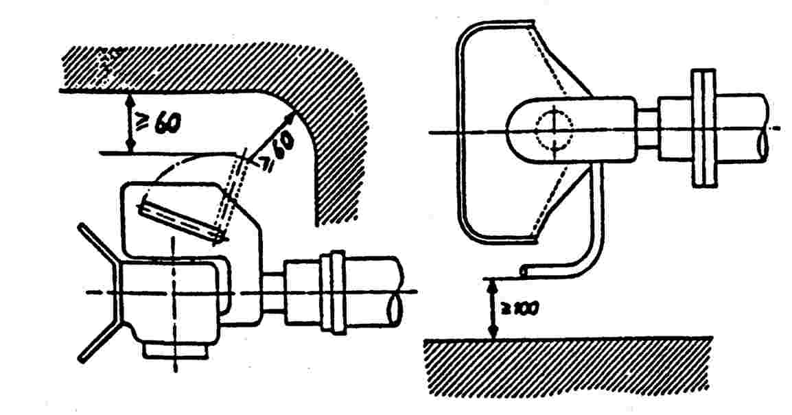
If one or more of the following rules regarding easy and safe operation (Section 2.3.3), accessibility (Section 2.3.4) or clearance for the hand lever (Section 2.3.5) cannot be met, a coupling with a remote control device as described in Annex V, Section 10.3 must be used.
2.3.3. Easy and safe coupling operation
Drawbar couplings must be mounted on the vehicle type in such a manner that they are easy and safe to operate.
In addition to the functions of opening (and closing, if applicable) this also includes checking the position of the indicator for the closed and secured position of the coupling pin (by sight and touch).
In the area in which the person operating the coupling must stand, there must be no points of possible danger such as sharp edges, corners, etc. inherent in the design or they must be protected so that injury is unlikely.
The way of escape from this area must not be restricted or barred on either side by any attached objects.
Any underrun protection device must not prevent the person adopting a suitable position to operate the coupling.
2.3.4. Accessibility
The distance between the centre of the coupling pin and the rear edge of the vehicle bodywork must not exceed 420 mm.
However, the distance of 420 mm may be exceeded if technical necessity can be demonstrated:
|
1. |
a distance of up to 650 mm for vehicles with tipping bodies or rear-mounted equipment; |
|
2. |
a distance of up to 1 320 mm if the unobstructed height is at least 1 150 mm; |
|
3. |
car transporters with at least two loading levels when the trailer vehicle is not separated from the towing vehicle in normal transport operation, |
provided easy and safe actuation of the drawbar coupling is not adversely affected.
2.3.5. Clearance for the hand lever
In order to permit safe operation of drawbar couplings there must be adequate free space around the hand lever.
The clearance illustrated in figure 33 is regarded as sufficient. If different types of standard drawbar couplings are intended to be fitted to the vehicle type, the clearance must be such that the conditions are also satisfied for the largest size of coupling of the appropriate class given in Annex V, Section 3.
The dimensions are also applicable as appropriate for drawbar couplings having hand levers pointing downwards or of a different design.
The clearance must also be maintained within the specified minimum angle for coupling-up and uncoupling given in Annex V, Section 3.6.
2.3.6. Clearance for free movement of drawbar coupling
The drawbar coupling attached to the vehicle must have a minimum clear gap of 10 mm from every other part of the vehicle taking into account all possible geometrical positions in accordance with Annex V.
If different types of standard drawbar couplings are intended to be fitted to the vehicle type, the clearance must be such that the conditions are also satisfied for the largest possible coupling of the appropriate class stated in Annex V, Section 3.
2.3.7. Admissibility of drawbar couplings with a special joint for vertical rotation (see Figure 6).
Couplings having a cylindrical pin and which achieve vertical rotation for the coupled drawbar eye by means of a special joint will only be permitted in cases when technical necessity can be demonstrated. This may be the case, for example, on rear tippers when the coupling head must be hinged, or with the couplings of heavy transporters when for strength reasons the use of a cylindrical coupling pin is necessary.
TABLE 8
Mounting dimensions for standard drawbar couplings
|
|
C 50-1 |
C 50-2 |
C 50-3 |
C 50-4 |
C 50-5 |
C 50-6 |
Remarks |
|
e1 |
83 |
120 |
140 |
160 |
± 0,5 |
||
|
e2 |
56 |
55 |
80 |
100 |
± 0,5 |
||
|
d1 |
— |
54 |
75 |
85 |
95 |
+ 1/-0,5 |
|
|
d1 |
10,5 |
15 |
17 |
21 |
H13 |
||
|
T |
— |
15 |
20 |
35 |
35 |
35 |
maximum |
|
F |
120 |
165 |
190 |
210 |
minimum |
||
|
G |
95 |
100 |
130 |
150 |
minimum |
||
|
L1 |
— |
200 |
300 |
|
400 |
minimum |
|
2.4. Attachment of drawbar eyes and drawbars on trailers.
|
2.4.1. |
Drawbars for centre-axle trailers must have a support device adjustable in height if the vertical bearing load at the drawbar eye on the trailer type exceeds 50 kg, when the trailer is uniformly loaded to its technically permissible maximum mass. |
|
2.4.2. |
When attaching drawbar eyes and drawbars to centre-axle trailers with a maximum mass C of more than 3,5 tonnes and more than one axle, they must be equipped with a device for axle load sharing. |
2.5. Attachment of fifth wheel couplings, mounting plates and coupling pins on vehicles.
|
2.5.1. |
Class G 50 fifth wheel couplings must not be mounted directly on the vehicle frame unless permitted by the vehicle manufacturer. They must be fixed to the frame by means of the mounting plate, the installation instructions provided by the vehicle manufacturer or coupling manufacturer must be followed. |
|
2.5.2. |
Semi-trailers must be equipped with landing gear or any other equipment which allows uncoupling and parking of the semi-trailer. If semi-trailers are equipped so that the connection of the coupling devices, the electrical systems and braking systems can be effected automatically, the trailer must have landing gear which retracts from the ground automatically after the semi-trailer has been coupled up. |
|
2.5.3. |
The fixing of the fifth wheel coupling pin in the mounting plate on the semi-trailer must be as instructed by the vehicle manufacturer or manufacturer of the fifth wheel coupling. |
|
2.5.4. |
If a semi-trailer is equipped with a steering wedge it must meet the requirements as described in Annex V, Sections 7.9.1 and 7.9.2. |
(1) The value V shall be given for vehicles having a technically permissible maximum laden mass exceeding 3,5 tonnes only.
ANNEX VIII
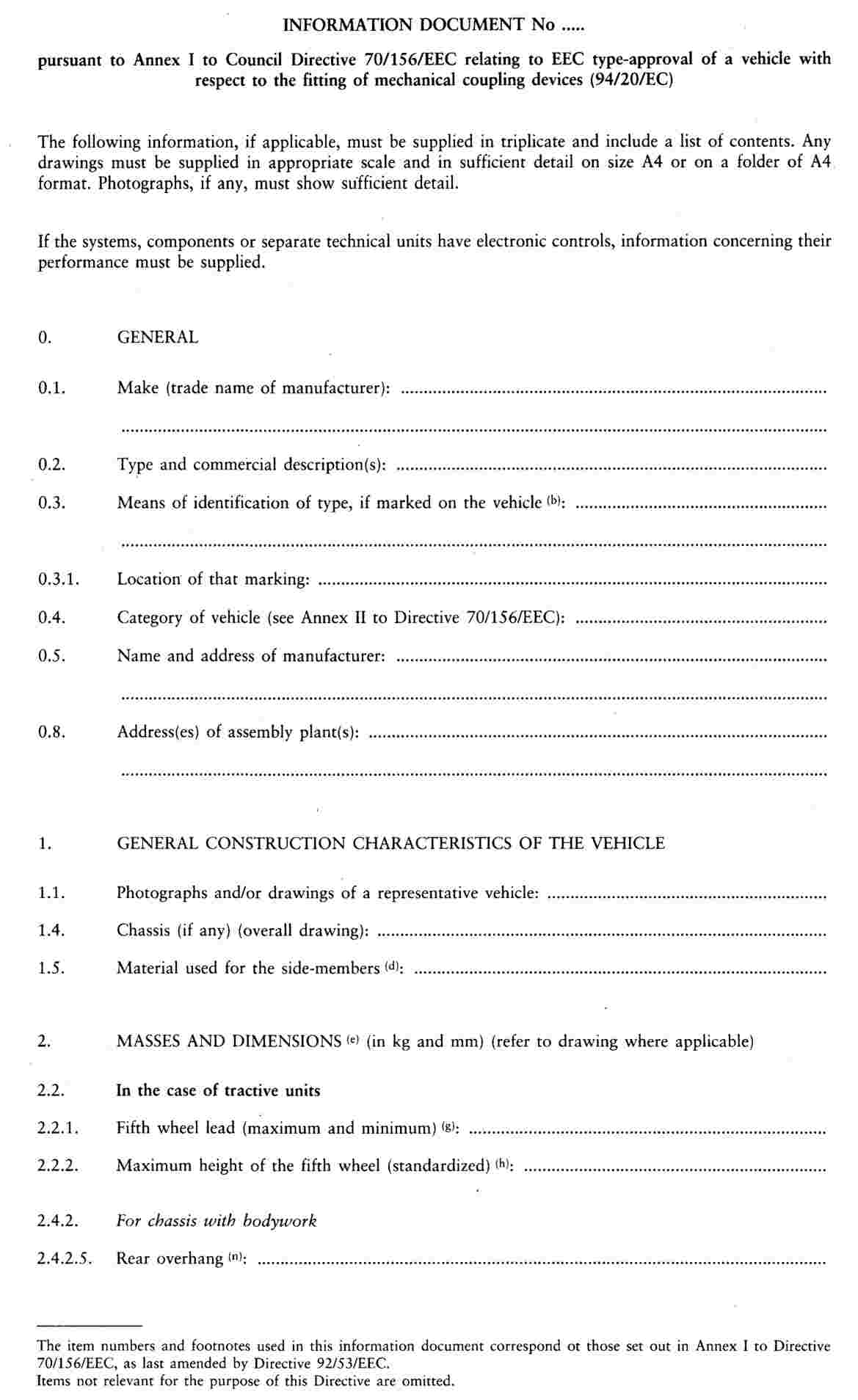


ANNEX IX

Appendix I
to EEC type-approval certificate No concerning the type-approval of a vehicle with regard to Directive 94/20/EC
