ANNEX
DIRECTIVE 96/48/EC — INTEROPERABILITY OF THE TRANS-EUROPEAN HIGH SPEED RAIL SYSTEM
TECHNICAL SPECIFICATION FOR INTEROPERABILITY
‘Energy’ Sub-System
|
1. |
INTRODUCTION | 9 |
|
1.1. |
Technical scope | 9 |
|
1.2. |
Geographical scope | 9 |
|
1.3. |
Content of this TSI | 9 |
|
2. |
SUBSYSTEM DEFINITION/SCOPE | 10 |
|
2.1. |
Scope | 10 |
|
2.2. |
Definition of the subsystem | 10 |
|
2.2.1. |
Electrification system | 10 |
|
2.2.2. |
Geometry of Overhead contact line and pantograph | 11 |
|
2.2.3. |
Interaction of overhead contact line and pantograph | 11 |
|
2.2.4. |
Transition between high-speed lines and other lines | 11 |
|
2.3. |
Links with other subsystems and within the subsystem | 11 |
|
2.3.1. |
Introduction | 11 |
|
2.3.2. |
Links concerning electrification system | 11 |
|
2.3.3. |
Links concerning overhead line equipment and pantographs | 12 |
|
2.3.4. |
Links concerning interaction of overhead contact line and pantograph | 12 |
|
2.3.5. |
Links concerning phase and system separation sections | 12 |
|
3. |
ESSENTIAL REQUIREMENTS | 12 |
|
3.1. |
General | 12 |
|
3.2. |
essential requirements for the energy subsystem | 13 |
|
3.3. |
specific aspects for the energy subsystem | 13 |
|
3.3.1. |
Safety | 13 |
|
3.3.2. |
Reliability and availability | 14 |
|
3.3.3. |
Health | 14 |
|
3.3.4. |
Environmental protection | 14 |
|
3.3.5. |
Technical compatibility | 15 |
|
3.3.6. |
Maintenance | 15 |
|
3.3.7. |
Operations | 15 |
|
3.4. |
essential requirements summary table | 16 |
|
4. |
CHARACTERISATION OF THE SUBSYSTEM | 19 |
|
4.1. |
Introduction | 19 |
|
4.2. |
functional and technical specifications of the subsystem | 19 |
|
4.2.1. |
General provisions | 19 |
|
4.2.2. |
Voltage and frequency | 19 |
|
4.2.3. |
System performance and installed power | 20 |
|
4.2.4. |
Regenerative braking | 20 |
|
4.2.5. |
Harmonic emissions towards the power utility | 20 |
|
4.2.6. |
External electromagnetic compatibility | 20 |
|
4.2.7. |
Continuity of power supply in case of disturbances | 21 |
|
4.2.8. |
Protection of the environment | 21 |
|
4.2.9. |
Overhead contact line | 21 |
|
4.2.9.1. |
Overall design | 21 |
|
4.2.9.2. |
Geometry of overhead contact line | 21 |
|
4.2.10. |
Compliance of the overhead contact line system with infrastructure gauge | 22 |
|
4.2.11. |
Contact wire material | 22 |
|
4.2.12. |
Contact wire wave propagation speed | 22 |
|
4.2.13. |
Not used | 22 |
|
4.2.14. |
Static contact force | 22 |
|
4.2.15. |
Mean contact force | 23 |
|
4.2.16. |
Dynamic behaviour and quality of current collection | 24 |
|
4.2.16.1. |
Requirements | 24 |
|
4.2.16.2. |
Conformity Assessment | 25 |
|
4.2.16.2.1. |
Interoperability Constituent Overhead Contact Line | 25 |
|
4.2.16.2.2. |
Interoperability Constituent Pantograph | 25 |
|
4.2.16.2.3. |
IC OCL in a newly installed line (Integration into a Subsystem) | 26 |
|
4.2.16.2.4. |
IC Pantograph integrated into new rolling stock | 26 |
|
4.2.16.2.5. |
Statistical calculations and simulations | 26 |
|
4.2.17. |
Vertical movement of the contact point | 26 |
|
4.2.18. |
Current capacity of the overhead contact line system: AC and DC systems, trains in motion | 27 |
|
4.2.19. |
Pantograph spacing used for the design of the overhead contact line | 27 |
|
4.2.20. |
Current capacity, DC systems, trains at standstill | 27 |
|
4.2.21. |
Phase separation sections | 28 |
|
4.2.22. |
System separation sections | 29 |
|
4.2.22.1. |
General | 29 |
|
4.2.22.2. |
Pantographs raised | 29 |
|
4.2.22.3. |
Pantographs lowered | 29 |
|
4.2.23. |
Electrical Protection Coordination Arrangements | 30 |
|
4.2.24. |
Effects of DC operation on AC systems | 30 |
|
4.2.25. |
Harmonics and Dynamic Effects | 30 |
|
4.3. |
Functional and technical specifications for the interfaces | 30 |
|
4.3.1. |
High Speed Rolling stock subsystem | 30 |
|
4.3.2. |
High Speed Infrastructure subsystem | 32 |
|
4.3.3. |
High Speed Control-Command and Signalling subsystem | 32 |
|
4.3.4. |
High Speed Traffic Operations and Management | 32 |
|
4.3.5. |
Safety in Railway Tunnels | 32 |
|
4.4. |
Operating rules | 33 |
|
4.4.1. |
Management of power supply in case of danger | 33 |
|
4.4.2. |
Execution of works | 33 |
|
4.4.3. |
Day-to-day management of power supply | 33 |
|
4.5. |
Maintenance of power supply and overhead contact line system | 33 |
|
4.5.1. |
Manufacturer's Responsibility | 33 |
|
4.5.2. |
Infrastructure Manager's Responsibility | 33 |
|
4.6. |
Professional competences | 34 |
|
4.7. |
Health and safety conditions | 34 |
|
4.7.1. |
Protective provisions of substations and posts | 34 |
|
4.7.2. |
Protective provisions of overhead contact line system | 34 |
|
4.7.3. |
Protective provisions of current return circuit | 34 |
|
4.7.4. |
Other general requirements | 34 |
|
4.7.5. |
High Visibility Clothing | 35 |
|
4.8. |
Infrastructure and rolling stock registers | 35 |
|
4.8.1. |
Infrastructure Register | 35 |
|
4.8.2. |
Rolling Stock Register | 35 |
|
5. |
INTEROPERABILITY CONSTITUENTS | 35 |
|
5.1. |
Definitions | 35 |
|
5.2. |
Innovative solutions | 35 |
|
5.3. |
List of interoperability constituents | 35 |
|
5.4. |
Constituents’ performances and specifications | 36 |
|
5.4.1. |
Overhead contact line | 36 |
|
5.4.1.1. |
Overall design | 36 |
|
5.4.1.2. |
Geometry | 36 |
|
5.4.1.3. |
Current capacity | 36 |
|
5.4.1.4. |
Contact wire material | 36 |
|
5.4.1.5. |
Current at standstill | 36 |
|
5.4.1.6. |
Wave propagation speed | 36 |
|
5.4.1.7. |
Design for pantograph spacing | 36 |
|
5.4.1.8. |
Mean contact force | 36 |
|
5.4.1.9. |
Dynamic behaviour and quality of current collection | 36 |
|
5.4.1.10. |
Vertical movement of contact point | 36 |
|
5.4.1.11. |
Space for uplift | 36 |
|
6. |
ASSESSMENT OF CONFORMITY AND/OR SUITABILITY FOR USE | 36 |
|
6.1. |
Interoperability constituents | 36 |
|
6.1.1. |
Assessment procedures and modules | 36 |
|
6.1.2. |
Application of modules | 37 |
|
6.1.2.1. |
General | 37 |
|
6.1.2.2. |
Existing solutions for Interoperability Constituents | 37 |
|
6.1.2.3. |
Innovative solutions for Interoperability Constituents | 37 |
|
6.2. |
Energy subsystem | 38 |
|
6.2.1. |
Assessment procedures and modules | 38 |
|
6.2.2. |
Application of modules | 38 |
|
6.2.2.1. |
General | 38 |
|
6.2.2.2. |
Innovative solutions | 38 |
|
6.2.3. |
Assessment of maintenance | 39 |
|
6.3. |
Validity of certificates issued against the previous published version of the TSI | 39 |
|
6.4. |
Interoperable constituents not holding an ec declaration | 39 |
|
6.4.1. |
General | 39 |
|
6.4.2. |
The transition period | 39 |
|
6.4.3. |
The certification of subsystems containing non-certified interoperability constituents during the transition period | 39 |
|
6.4.3.1. |
Conditions | 39 |
|
6.4.3.2. |
Notification | 40 |
|
6.4.3.3. |
Lifecycle Implementation | 40 |
|
6.4.4. |
Monitoring arrangements | 40 |
|
7. |
IMPLEMENTATION OF THE ENERGY TSI | 40 |
|
7.1. |
Application of this tsi to new high-speed lines being put into service | 40 |
|
7.2. |
Application of this tsi to high-speed lines already in service | 41 |
|
7.2.1. |
Introduction | 41 |
|
7.2.2. |
Classification of works | 41 |
|
7.2.3. |
Parameters and specifications concerning the complete subsystem | 41 |
|
7.2.4. |
Parameters concerning the mechanical parts of the OCL and the power supply | 41 |
|
7.2.5. |
Parameters concerning the contact wire | 42 |
|
7.2.6. |
Parameters related to other directives, to operational and maintenance | 42 |
|
7.2.7. |
Scope of application | 42 |
|
7.3. |
TSI revision | 43 |
|
7.4. |
Specific cases | 43 |
|
7.4.1. |
Particular features on the Austrian network | 43 |
|
7.4.2. |
Particular features on the Belgian network | 43 |
|
7.4.3. |
Particular features on the German network | 44 |
|
7.4.4. |
Particular features on the Spanish network | 44 |
|
7.4.5. |
Particular features on the French network | 44 |
|
7.4.6. |
Particular features on the British network | 45 |
|
7.4.7. |
Particular features on the Eurotunnel network | 46 |
|
7.4.8. |
Particular features on the Italian network | 46 |
|
7.4.9. |
Particular features on the Irish and Northern Irish networks | 46 |
|
7.4.10. |
Particular features on the Swedish network | 46 |
|
7.4.11. |
Particular features on the Finnish network | 47 |
|
7.4.12. |
Particular features on the Polish network | 47 |
|
7.4.13. |
Particular features on the Danish network including the Öresund link to Sweden. | 47 |
|
7.4.14. |
Particular features on the Norwegian network — For information only | 47 |
|
7.4.15. |
Particular features on the Swiss network — For information only | 48 |
|
7.4.16. |
Particular features on the Lithuanian network | 48 |
|
7.4.17. |
Particular features on the Netherlands network | 48 |
|
7.4.18. |
Particular features on the Slovakian network | 48 |
|
7.5. |
Agreements | 48 |
|
7.5.1. |
Existing agreements | 48 |
|
7.5.2. |
Future agreements | 49 |
|
ANNEX A: |
CONFORMITY MODULES | 50 |
|
A.1. |
List of the modules | 50 |
|
A.2. |
Modules for interoperability constituents | 50 |
| Module A1: Internal Design Control with Production Verification | 50 |
| Module B: Type Examination | 52 |
| Module C: Conformity to type | 54 |
| Module H1: Full Quality Management System | 55 |
| Module H2: Full Quality Management System with Design Examination | 58 |
|
A.3. |
Modules for subsystems | 62 |
| Module SG: Unit verification | 62 |
| Module SH2: Full Quality Management System with Design Examination | 65 |
|
A.4. |
Assessment of maintenance arrangements: conformity assessment procedure | 71 |
|
ANNEX B: |
CONFORMITY ASSESSMENT OF INTEROPERABILITY CONSTITUENTS | 72 |
|
ANNEX C: |
ASSESSMENT OF THE ENERGY SUBSYSTEM | 73 |
|
ANNEX D: |
INFRASTRUCTURE REGISTER, INFORMATION ON THE ENERGY SUBSYSTEM | 75 |
|
ANNEX E: |
ROLLING STOCK REGISTER, INFORMATION REQUIRED BY THE ENERGY SUBSYSTEM | 76 |
|
ANNEX F: |
SPECIFIC CASE — GREAT BRITAIN — PANTOGRAPH ENVELOPE | 77 |
| ANNEXES G TO K ARE NOT USED | 79 |
|
ANNEX L: |
LIST OF OPEN POINTS | 79 |
1. INTRODUCTION
1.1. Technical scope
This TSI concerns the Energy subsystem of the trans-European high-speed rail system. The energy subsystem is one of the subsystems listed in Annex II(1) to Directive 96/48/EC as modified by Directive 2004/50/EC.
According to Annex I of the Directive, high-speed lines comprise:
|
— |
specially built high-speed lines equipped for speeds generally equal to or greater than 250 km/h, |
|
— |
specially upgraded high-speed lines equipped for speeds of the order of 200 km/h, |
|
— |
specially upgraded high-speed lines or lines specially built for high speed, which have special features as a result of topographical or environmental, relief or town-planning constraints, on which speed must be adapted individually |
In this TSI, these lines have been classified as category I, category II and category III respectively.
1.2. Geographical scope
The geographical scope of this TSI is the trans-European high-speed rail system as described in Annex I to Directive 96/48/EC as modified by Directive 2004/50/EC.
Reference shall be made in particular to the lines of the trans-European rail network described in Decision No 1692/96/EC of the European Parliament and of the Council of 23 July 1996 as modified by Decision No 884/2004/EC on Community guidelines for the development of the trans-European transport network or in any subsequent update to the same Decision as a result of the revision provided for in Article 21 of that Decision.
1.3. Content of this TSI
In accordance with Article 5(3) of Directive 96/48/EC as modified by Directive 2004/50/EC, this TSI:
|
(a) |
indicates its intended scope (chapter 2); |
|
(b) |
lays down essential requirements for the Energy subsystem (chapter 3) and its interfaces vis-à-vis other subsystems (chapter 4); |
|
(c) |
establishes the functional and technical specifications to be met by the subsystem and its interfaces vis-à-vis other subsystems (chapter 4); |
|
(d) |
determines the interoperability constituents and interfaces which shall be covered by European specifications, including European standards, which are necessary to achieve interoperability within the trans-European high speed rail system (chapter 5); |
|
(e) |
states, in each case under consideration, which procedures are to be used in order to assess the conformity or the suitability for use of the interoperability constituents, or the EC verification of the subsystems (chapter 6); |
|
(f) |
indicates the strategy for implementing this TSI (chapter 7); |
|
(g) |
indicates for the staff concerned, the professional competencies and health and safety conditions at work required for the operation and maintenance of the subsystem, as well as for the implementation of the TSI (chapter 4). |
In accordance with Article 6(3) of the Directive, provision may be made for specific cases for each TSI; these are indicated in chapter 7.
This TSI also sets out, in chapter 4, the operating and maintenance rules specific to the scope indicated in paragraphs 1.1 and 1.2 above.
2. SUBSYSTEM DEFINITION/SCOPE
2.1. Scope
The Energy TSI specifies those requirements which are necessary to assure the interoperability of the trans-European high-speed rail system. This TSI covers the trackside part of the Energy subsystem and the part of the Maintenance subsystem that relates to the trackside part of the Energy subsystem. The Energy subsystem of the trans-European high-speed rail system comprises all fixed installations that are required to supply, with respect to the essential requirements, the trains from high-voltage single-phase or three-phase networks.
The energy subsystem also includes the definition and quality criteria for interaction between pantograph and overhead contact line.
The Energy subsystem consists of:
|
— |
substations: connected on their primary side to the high-voltage grid, with transformation of the high-voltage to a voltage and/or conversion to a power supply system suitable for the trains. On the secondary side, substations are connected to the railway overhead contact line system; |
|
— |
sectioning points: electrical equipment located at intermediate locations between substations to supply and parallel overhead contact lines and to provide protection, isolation, auxiliary supplies; |
|
— |
overhead contact line system: a system that distributes the electrical energy to the trains running on the route and transmits it to the trains by means of pantographs. The overhead contact line system is also equipped with manually or remotely controlled disconnectors which are required to isolate sections or groups of the overhead contact line system according to operational necessity. Feeder lines are part of the overhead contact line system; |
|
— |
return circuit: all conductors which form the intended path of the traction return current and the current under fault conditions. Therefore, so far as this aspect is concerned, the return circuit is part of the Energy subsystem and has an interface with the Infrastructure subsystem; |
Pantographs transmit electrical energy from the overhead contact line system to the train on which they are installed. The pantograph is integrated into and put into service with the train, and is in the scope of the High Speed Rolling Stock TSI. The interaction between pantograph and the overhead contact line is specified in this TSI.
2.2. Definition of the subsystem
2.2.1. Electrification system
As with any electrical device, a train is designed to operate correctly with a nominal voltage and a nominal frequency applied at its terminals, i.e. the pantograph(s) and wheels. Variations and limits of these parameters need to be defined in order to assure the anticipated train performance.
High-speed trains need a correspondingly high power. In order to supply the trains with minimum resistive losses, it is necessary to have a high supply voltage and (correspondingly) a lower current. The power supply system has to be designed such that every train will be supplied with the necessary power. Therefore, the power consumption of each train and the operating schedule are important aspects for performance.
Modern trains are often capable of using regenerative braking to return energy to the power supply, reducing power consumption overall. Therefore, the power supply system has to be designed to accept regenerative braking energy.
In any electrical system, short-circuits and other fault conditions occur. The electrification system needs to be designed so that the subsystem controls detect these faults immediately and trigger measures to remove the short-circuit current and isolate the affected part of the circuit. After such events, the electrification system has to be able to restore supply to all installations as soon as possible to resume operations.
2.2.2. Geometry of Overhead contact line and pantograph
The compatible geometry of the overhead contact line and the pantograph is an important aspect of interoperability. As far as geometrical interaction is concerned, the height of the contact wire above the rails, the lateral deviation in still air and under wind pressure and the contact force have to be specified. The geometry of the pantograph head is also fundamental to assure good interaction with the overhead contact line, taking into account vehicle sway.
2.2.3. Interaction of overhead contact line and pantograph
At the high speeds envisaged for the trans-European high-speed rail system, the interaction of overhead contact line and pantograph represents a very important aspect in establishing reliable power transmission without undue disturbances to railway installations and the environment. This interaction is mainly determined by:
|
— |
static and aerodynamic effects dependant upon the nature of the pantograph contact strips and the design of the pantograph, the shape of the vehicle on which the pantograph(s) is (are) mounted and the position of the pantograph on the vehicle, |
|
— |
the compatibility of the contact strip material with the contact wire, |
|
— |
the dynamic characteristics of the overhead contact line and pantograph(s), |
|
— |
the protection of the pantograph(s) and overhead contact line in the case of a broken pantograph contact strip, |
|
— |
the number of pantographs in service and the distance between them, since each pantograph can interfere with the others on the same overhead contact line section. |
2.2.4. Transition between high-speed lines and other lines
Along a line of route, different requirements will apply. The transition between sections having different requirements affects the power supply and overhead contact line system and is, therefore, an aspect to be dealt with in the Energy TSI.
2.3. Links with other subsystems and within the subsystem
2.3.1. Introduction
The Energy subsystem has links with other subsystems of the trans-European high-speed rail system in order to achieve the envisaged performance. These links are covered by the definition of interfaces and performance criteria.
2.3.2. Links concerning electrification system
|
— |
Voltage and frequency and their permissible ranges interface with the High Speed Rolling Stock subsystem. |
|
— |
The power installed on the lines and the specified power factor determines the performance of the high-speed rail system and interfaces with the High Speed Rolling Stock subsystem. |
|
— |
Regenerative braking reduces energy consumption and interfaces with the High Speed Rolling Stock subsystem. |
|
— |
Electrical fixed installations and on-board traction equipment need to be protected against short circuits. Circuit breaker tripping in substations and on trains has to be coordinated. Electrical protection interfaces with the High Speed Rolling Stock subsystem. |
|
— |
Electrical interference and harmonic emissions interface with the High Speed Rolling Stock and Control-Command and Signalling subsystems. |
2.3.3. Links concerning overhead line equipment and pantographs
|
— |
On high-speed lines, the contact wire height needs special attention in order to avoid excessive wear. The contact wire height interfaces with the Infrastructure and High Speed Rolling Stock subsystems. |
|
— |
Vehicle and pantograph sway interfaces with the Infrastructure subsystem. |
2.3.4. Links concerning interaction of overhead contact line and pantograph
The quality of current collection depends on the number of pantographs in service, their spacing and other traction-unit-specific details. The arrangement of pantographs interfaces with the Energy subsystem.
2.3.5. Links concerning phase and system separation sections
|
— |
To pass transitions of electrification systems and phase separation sections, without bridging, the number and arrangement of pantographs on trains shall be stipulated. This interfaces with the High Speed Rolling Stock subsystem |
|
— |
To pass transitions of electrification systems and phase separation sections, without bridging, control of train current is required. This interfaces with the Control-Command and Signalling subsystem. |
|
— |
When passing through system separation sections, lowering of pantograph(s) may be required. This interfaces with the Control-Command and Signalling subsystem. |
3. ESSENTIAL REQUIREMENTS
3.1. General
In the scope of this TSI, compliance with the specifications described in:
|
— |
chapter 4 for the subsystem |
|
— |
chapter 5 for the interoperability constituents, |
as demonstrated by a positive result of the assessment of:
|
— |
conformity and/or suitability for use of the interoperability constituents, |
|
— |
and verification of the subsystem, |
as described in chapter 6 ensures fulfilment of the relevant essential requirements quoted in sections 3.2 and 3.3 of this TSI.
Nevertheless, if part of the essential requirements are covered by national rules because of
|
— |
open and reserved points declared in the TSI, |
|
— |
derogation under article 7 of the Directive 96/48/EC as modified by the Directive 2004/50/EC, |
|
— |
specific cases described in section 7.4 of this TSI, |
the corresponding conformity assessment shall be carried out according to procedures under the responsibility of the Member State concerned.
According to Article 4(1) of Directive 96/48/EC as modified by the Directive 2004/50/EC, the trans-European high-speed rail system, its subsystems and its interoperability constituents shall fulfil the essential requirements set out in general terms in Annex III to the Directive.
3.2. Essential requirements for the Energy subsystem
The essential requirements cover:
|
— |
safety, |
|
— |
reliability and availability, |
|
— |
health, |
|
— |
environmental protection, |
|
— |
technical compatibility. |
3.3. Specific aspects for the Energy subsystem
3.3.1. Safety
According to Annex III to Directive 96/48/EC as modified by the Directive 2004/50/EC, the essential requirements for safety are the following:
|
1.1.1. |
The design, construction or assembly, maintenance and monitoring of safety-critical components, and more particularly of the components involved in train movement must be such as to guarantee safety at the level corresponding to the aims laid down for the network, including those for specific degraded situations. |
|
1.1.2. |
The parameters involved in the wheel/rail contact must meet the stability requirements needed in order to guarantee safe movement at the maximum authorised speed. |
|
1.1.3. |
The components used must withstand any normal or exceptional stress that has been specified during their period in service. The safety repercussion of any accidental failure must be limited by appropriate means. |
|
1.1.4. |
The design of fixed installations and rolling stock and the choice of the materials used must be aimed at limiting the generation, propagation and effects of fire and smoke in the event of a fire. |
|
1.1.5. |
Any devices intended to be handled by users must be so designed as not to impair their safety if used foreseeably in a manner not in accordance with the posted instructions. |
The aspects mentioned under 1.1.2 and 1.1.5 are not relevant to the Energy subsystem.
In order to satisfy the essential requirements 1.1.1, 1.1.3 and 1.1.4 above, the Energy subsystem shall be designed and constructed so that the requirements set out in clauses 4.2.4, 4.2.7, 4.2.9 to 4.2.16, 4.2.18 to 4.2.25, 4.4.1, 4.4.2, 4.5 and 4.7.1 to 4.7.3 are met and the interoperability constituents used comply with the requirements set out in clause 5.4.1.1 to 5.4.1.5, 5.4.1.7 to 5.4.1.9 and 5.4.1.11.
The following essential requirement for safety according to Annex III to Directive 96/48/EC as modified by Directive 2004/50/EC is especially of concern for the Energy subsystem.
|
2.2.1. |
Operation of the energy supply systems must not impair the safety either of high-speed trains or persons (users, operating staff, trackside dwellers and third parties). |
In order to satisfy the essential requirement 2.2.1 above, the Energy subsystem shall be designed and constructed so that the requirements set out in clauses 4.2.4 to 4.2.7, 4.2.18, 4.2.20 to 4.2.25, 4.4.1, 4.4.2, 4.5, and 4.7.1 to 4.7.4 are met and the interoperability constituents used comply with the requirements set out in clause 5.4.1.2, 5.4.1.3, 5.4.1.5, 5.4.1.8 to 5.4.1.11.
3.3.2. Reliability and availability
According to Annex III to Directive 96/48/EC as modified by Directive 2004/50/EC, the essential requirement as far as reliability and availability are concerned is the following.
|
1.2. |
The monitoring and maintenance of fixed or moveable components that are involved in train movements must be organised, carried out and quantified in such a manner as to maintain their operation under the intended conditions. |
In order to satisfy the essential requirement 1.2, the Energy subsystem shall be maintained such that the requirements set out in clause 4.2.7, 4.2.18, 4.4.2, 4.5 are met.
3.3.3. Health
According to Annex III to Directive 96/48/EC as modified by Directive 2004/50/EC, the essential requirements for health are the following:
|
1.3.1. |
Materials likely, by virtue of the way they are used, to constitute a health hazard to those having access to them must not be used in trains and railway infrastructures. |
|
1.3.2. |
Those materials must be selected, deployed and used in such a way as to restrict the emission of harmful and dangerous fumes or gases, particular in the event of fire. |
In order to satisfy the essential requirements 1.3.1 and 1.3.2, the Energy subsystem shall be designed and constructed so that the requirements set out in clauses 4.2.11, 4.5, 4.7.1 to 4.7.4 are met and the interoperability constituents used comply with the requirements set out in clause 5.4.1.4.
3.3.4. Environmental protection
According to Annex III to Directive 96/48/EC as modified by Directive 2004/50/EC, essential requirements for environmental protection are the following:
|
1.4.1. |
The repercussions on the environment of the establishment and operation of the trans-European high-speed rail system must be assessed and taken into account at the design stage of the system in accordance with the Community provisions in force. |
|
1.4.2. |
The materials used in trains and infrastructure must prevent the emissions of fumes and gases which are harmful and dangerous to the environment, particularly in the event of fire. |
|
1.4.3. |
The rolling stock and energy supply systems must be designed and manufactured in such a way as to be electromagnetically compatible with the installation equipment and public or private networks with which they might interfere. |
In order to satisfy essential requirements 1.4.1, 1.4.2 and 1.4.3, the Energy subsystem shall be designed and constructed so that the requirements set out in clauses 4.2.4 to 4.2.6, 4.2.8, 4.2.11, 4.2.16, 4.2.17, 4.2.21, 4.2.22, 4.2.24, 4.2.25 and 4.7.1 to 4.7.3 are met and the interoperability constituents used comply with the requirements set out in clauses 5.4.1.2, 5.4.16, 5.4.1.7, and 5.4.1.9 to 5.4.1.11.
The following essential requirement for environmental protection according to Annex III to Directive 96/48/EC as modified by Directive 2004/50/EC is especially of concern for the Energy subsystem:
|
2.2.2. |
The functioning of the energy supply systems must not interfere with the environment beyond specified limits. |
In order to satisfy essential requirement 2.2.2, the Energy subsystem shall be designed and constructed so that the requirements set out in clauses 4.2.6, 4.2.8, 4.2.12, 4.2.16, and 4.7.1 to 4.7.3 are met and the interoperability constituents used comply with the requirements set out in clauses 5.4.1.2, 5.4.1.6, 5.4.1.9 to 5.4.1.11.
3.3.5. Technical compatibility
According to Annex III to Directive 96/48/EC as modified by Directive 2004/50/EC, the essential requirements for technical compatibility are the following.
|
1.5. |
The technical characteristics of the infrastructures and fixed installations must be compatible which each other and with those of the trains on the trans-European high-speed rail system. If adherence to these characteristics proves difficult on certain sections of the network temporary solutions that ensure compatibility in the future may be implemented. |
In order to satisfy the essential requirement 1.5, the Energy subsystem shall be designed and constructed so that the requirements set out in clauses 4.2.1 to 4.2.4, 4.2.6, 4.2.9 to 4.2.25, 4.4.2, 4.5 and 4.7.1 to 4.7.3 are met and the interoperability constituents used comply with the requirements set out in clauses 5.4.1.1 to 5.4.1.11.
The following essential requirement for technical compatibility according to Annex III to Directive 96/48/EC as modified by Directive 2004/50/EC is especially of concern for the Energy subsystem:
|
2.2.3. |
The electrical supply systems used throughout the trans-European high-speed rail system must:
|
In order to satisfy essential requirement 2.2.3, the Energy subsystem shall be designed and constructed so that the requirements set out in clauses 4.2.1 to 4.2.4, 4.2.9, 4.2.11 to 4.2.22, and 4.5 are met and the interoperability constituents used comply with the requirements set out in clauses 5.4.1.1 to 5.4.1.11
3.3.6. Maintenance
According to Annex III to Directive 96/48/EC as modified by Directive 2004/50/EC, the essential requirements for maintenance are the following:
|
2.5.1. |
The technical installations and the procedures used in the maintenance centres must not constitute a danger to human health. |
|
2.5.2. |
The technical installations and the procedures used in the maintenance centres must not exceed the permissible levels of nuisance with regard to the surrounding environment. |
|
2.5.3. |
The maintenance installations on high-speed trains must be such as to enable safety, health and comfort operations to be carried out on all trains for which they have been designed. |
The aspects mentioned under 2.5.3 are not relevant to the Energy subsystem.
In the case of the Energy subsystem, maintenance is carried out not in maintenance centres but along the line. Maintenance is carried out by maintenance units, for which the requirements mentioned under 2.5.1 and 2.5.2 apply. In order to satisfy the essential requirements 2.5.1 and 2.5.2, the Energy subsystem Interoperability Constituent shall be designed and constructed so that the requirements set out in clauses 4.2.8, 4.5 and 4.7.4 are met.
3.3.7. Operations
According to Annex III to Directive 96/48/EC as modified by Directive 2004/50/EC, the essential requirements for operation are the following:
|
2.7.1. |
Alignment of the network operating rules and the qualifications of drivers and on-board staff must he such as to ensure safe international operation. The operations and maintenance intervals, the training and qualifications of maintenance staff and the quality assurance system set up in the maintenance centres of the operators concerned must be such as to ensure a high level of safety. |
|
2.7.2. |
The operation and maintenance periods, the training and qualifications of the maintenance staff and the quality assurance system set up by the operators concerned in the maintenance centres must be such as to ensure a high level of system reliability and availability. |
|
2.7.3. |
The alignment of the operating rules of the networks and the qualifications of drivers, on-board staff and managers in charge of traffic must be such as to ensure operating efficiency on the trans-European high-speed rail system. |
In case of the Energy subsystem, maintenance is carried out not in maintenance centres but along the line. Maintenance is carried out by maintenance units. In order to satisfy the essential requirements 2.7.1 to 2.7.3, the Energy subsystem and Interoperability Constituent shall be designed and constructed so that the requirements set out in clauses 4.2.4, 4.2.21 to 4.2.23, 4.4.1, 4.4.2, 4.5, 4.6 and 4.7.1 to 4.7.4 are met.
3.4. Essential Requirements Summary Table
The clauses addressing each of the Essential Requirements are set out below in Table 3.4; where an X is marked in the column, the Essential Requirement is addressed by the clause listed on the left.
Table 3.4
|
Clause number |
Clause Title |
Safety |
R&A |
Health |
Environmental Protection |
Technical Compatibility |
Operations |
Maintenance |
|||||||||||
|
1.1.1 |
1.1.3 |
1.1.4 |
2.2.1 |
1.2 |
1.3.1 |
1.3.2 |
1.4.1 |
1.4.2 |
1.4.3 |
2.2.2 |
1.5 |
2.2.3 |
2.7.1 |
2.7.2 |
2.7.3 |
2.5.1 |
2.5.2 |
||
|
4.2.1 |
General provisions |
— |
— |
— |
— |
— |
— |
— |
— |
— |
— |
— |
X |
X |
— |
— |
— |
— |
— |
|
4.2.2 |
Voltage and frequency |
— |
— |
— |
X |
— |
— |
— |
— |
— |
— |
— |
X |
X |
— |
— |
— |
— |
— |
|
4.2.3 |
System performance and installed power |
— |
— |
— |
— |
— |
— |
— |
— |
— |
— |
— |
X |
X |
— |
— |
— |
— |
— |
|
4.2.4 |
Regenerative braking |
— |
X |
— |
X |
— |
— |
— |
X |
— |
— |
— |
X |
X |
X |
— |
— |
— |
— |
|
4.2.5 |
Harmonic emissions towards the power utility |
— |
— |
— |
X |
— |
— |
— |
— |
— |
X |
— |
— |
— |
— |
— |
— |
— |
— |
|
4.2.6 |
External electromagnetic compatibility |
— |
— |
— |
X |
— |
— |
— |
X |
— |
X |
X |
X |
— |
— |
— |
— |
— |
— |
|
4.2.7 |
Continuity of power supply in case of disturbances |
X |
X |
— |
X |
X |
— |
— |
— |
— |
— |
— |
— |
— |
— |
— |
X |
— |
— |
|
4.2.8 |
Protection of the environment |
— |
— |
— |
— |
— |
— |
— |
X |
X |
X |
X |
— |
— |
— |
— |
— |
— |
X |
|
4.2.9.1 |
Overall design |
X |
X |
X |
— |
— |
— |
— |
— |
— |
— |
— |
X |
X |
— |
— |
— |
— |
— |
|
4.2.9.2 |
Geometry of Overhead Contact Line |
X |
X |
— |
— |
— |
— |
— |
— |
— |
— |
— |
X |
X |
— |
— |
— |
— |
— |
|
4.2.10 |
Compliance of the Overhead Contact Line with Infrastructure Gauge |
X |
— |
— |
— |
— |
— |
— |
— |
— |
— |
— |
X |
— |
— |
— |
— |
— |
— |
|
4.2.11 |
Contact wire material |
X |
X |
X |
— |
— |
— |
X |
— |
— |
— |
— |
X |
X |
— |
— |
— |
— |
— |
|
4.2.12 |
Contact Wire Wave Propagation Speed |
— |
— |
— |
— |
— |
— |
— |
— |
— |
X |
X |
X |
X |
— |
— |
— |
— |
— |
|
4.2.14 |
Static contact force |
X |
X |
X |
X |
— |
— |
— |
— |
— |
— |
— |
X |
X |
— |
— |
— |
— |
— |
|
4.2.15 |
Mean contact force |
X |
X |
X |
X |
— |
— |
— |
— |
— |
— |
— |
X |
X |
— |
— |
— |
— |
— |
|
4.2.16 |
Requirements for dynamic behaviour and quality of current collection |
X |
X |
— |
X |
— |
— |
— |
— |
— |
X |
X |
X |
X |
— |
— |
— |
— |
— |
|
4.2.17 |
Vertical movement of the contact point |
— |
— |
— |
X |
— |
— |
— |
— |
— |
X |
— |
X |
X |
— |
— |
— |
— |
— |
|
4.2.18 |
Current capacity of the overhead contact line system |
X |
X |
X |
X |
— |
— |
— |
— |
— |
— |
— |
X |
X |
— |
— |
— |
— |
— |
|
4.2.19 |
Pantograph spacing used for the design of the overhead contact line |
— |
X |
— |
— |
— |
— |
— |
— |
— |
X |
— |
X |
X |
— |
— |
— |
— |
— |
|
4.2.20 |
Current at standstill (DC Systems) |
X |
X |
X |
X |
— |
— |
— |
— |
— |
— |
— |
X |
X |
— |
— |
— |
— |
— |
|
4.2.21 |
Phase Separation Sections |
X |
— |
X |
X |
— |
— |
— |
— |
— |
X |
— |
X |
X |
X |
— |
X |
— |
— |
|
4.2.22 |
System Separation Sections |
X |
— |
X |
X |
— |
— |
— |
— |
— |
X |
— |
X |
X |
X |
— |
X |
— |
— |
|
4.2.23 |
Electrical Protection Coordination Arrangements |
X |
X |
— |
X |
— |
— |
— |
— |
— |
— |
— |
X |
— |
X |
— |
X |
— |
— |
|
4.2.24 |
Effects of DC on AC Systems |
— |
X |
X |
X |
— |
— |
— |
— |
— |
X |
— |
X |
— |
— |
— |
— |
— |
— |
|
4.2.25 |
Harmonics and Dynamic Effects |
X |
X |
— |
X |
— |
— |
— |
— |
— |
X |
— |
X |
— |
— |
— |
— |
— |
— |
|
4.4.1 |
Management of power supply in case of danger |
X |
X |
— |
X |
— |
— |
— |
— |
— |
— |
— |
|
— |
X |
— |
X |
— |
— |
|
4.4.2 |
Execution of works |
X |
— |
— |
X |
X |
— |
— |
— |
— |
— |
— |
X |
— |
X |
X |
X |
— |
— |
|
4.5 |
Maintenance of power supply and overhead contact line system |
X |
X |
X |
X |
X |
X |
X |
— |
X |
— |
— |
X |
X |
X |
X |
X |
X |
X |
|
4.6 |
Professional competences |
— |
— |
— |
— |
— |
— |
— |
— |
— |
— |
— |
— |
— |
X |
X |
X |
— |
— |
|
4.7.1 |
Protective provisions of substations and posts |
X |
X |
X |
X |
— |
X |
X |
— |
— |
X |
X |
X |
— |
X |
— |
— |
— |
— |
|
4.7.2 |
Protective provisions of overhead contact line system |
X |
X |
X |
X |
— |
X |
X |
— |
— |
X |
X |
X |
— |
X |
— |
— |
— |
— |
|
4.7.3 |
Protective provisions of current return circuit |
X |
X |
X |
X |
— |
X |
X |
— |
— |
X |
X |
X |
X |
X |
— |
— |
— |
— |
|
4.7.4 |
Other general requirements |
— |
— |
— |
X |
— |
X |
X |
— |
— |
— |
— |
— |
— |
X |
X |
X |
X |
X |
|
5.4.1.1 |
Overall design |
X |
X |
X |
— |
— |
— |
— |
— |
— |
— |
— |
X |
X |
— |
— |
— |
— |
— |
|
5.4.1.2 |
Geometry |
X |
X |
— |
X |
— |
— |
— |
— |
— |
X |
X |
X |
X |
— |
— |
— |
— |
— |
|
5.4.1.3 |
Current capacity |
X |
X |
X |
X |
— |
— |
— |
— |
— |
— |
— |
X |
X |
— |
— |
— |
— |
— |
|
5.4.1.4 |
Contact wire material |
X |
X |
X |
— |
— |
— |
X |
— |
— |
— |
— |
X |
X |
— |
— |
— |
— |
— |
|
5.4.1.5 |
Current at standstill (DC Systems) |
X |
X |
X |
X |
— |
— |
— |
— |
— |
— |
— |
X |
X |
— |
— |
— |
— |
— |
|
5.4.1.6 |
Wave propagation speed |
— |
— |
— |
— |
— |
— |
— |
— |
— |
X |
X |
X |
X |
— |
— |
— |
— |
— |
|
5.4.1.7 |
Design for Pantograph Spacing |
— |
X |
— |
— |
— |
— |
— |
— |
— |
X |
— |
X |
X |
— |
— |
— |
— |
— |
|
5.4.1.8 |
Mean contact force |
X |
X |
X |
X |
— |
— |
— |
— |
— |
— |
— |
X |
X |
— |
— |
— |
— |
— |
|
5.4.1.9 |
Dynamic behaviour and quality of current collection |
X |
X |
— |
X |
— |
— |
— |
— |
— |
X |
X |
X |
X |
— |
— |
— |
— |
— |
|
5.4.1.10 |
Vertical Movement of the Contact Point |
— |
— |
— |
X |
— |
— |
— |
— |
— |
X |
— |
X |
X |
— |
— |
— |
— |
— |
|
5.4.1.11 |
Space for Uplift |
X |
X |
— |
X |
— |
— |
— |
— |
— |
X |
X |
X |
X |
— |
— |
— |
— |
— |
4. CHARACTERISATION OF THE SUBSYSTEM
4.1. Introduction
The trans-European high-speed rail system, to which Directive 96/48/EC as modified by Directive 2004/50/EC applies and of which the Energy subsystem is a part, is an integrated system whose compatibility shall be verified. This compatibility shall be checked in particular with regard to the specifications of the subsystem, its interfaces vis-à-vis the system in which it is integrated, as well as the operating and maintenance rules.
The functional and technical specifications of the subsystem and its interfaces, described in sections 4.2 and 4.3, do not impose the use of specific technologies or technical solutions, except where this is strictly necessary for the interoperability of the trans-European high speed rail network. But innovative solutions for interoperability may require new specifications and/or new assessment methods. In order to allow technological innovation, these specifications and assessment methods shall be developed by the process described in sections 6.1.2.3 and 6.2.2.2.
Taking account of all the applicable essential requirements, the Energy subsystem is characterised by the specifications set out in clauses 4.2 to 4.8.
For Specific Cases, see chapter 7.4; where reference is made to EN standards, any variations called ‘national deviations’ or ‘special national conditions’ in the EN do not apply. For EN clauses incorporating tables, column headings HS, UP, and Conn shall be taken to mean categories I, II and III respectively.
4.2. Functional and technical specifications of the subsystem
4.2.1. General provisions
The performance to be achieved by the Energy subsystem shall correspond to the relevant performance as specified for each category of line of the trans-European high-speed rail system, with respect to:
|
— |
the maximum line speed, and |
|
— |
the power demand of the trains at the pantographs. |
The Energy subsystem design shall assure the specified performance.
The Infrastructure Manager shall define, on a short section of route, connecting a high-speed line with another line, the position where the requirements of the Energy subsystem TSI for high-speed lines start to apply.
4.2.2. Voltage and frequency
Traction units need standardisation of the voltage and frequency values. Table 4.2.2 lists the nominal voltages and nominal frequencies of the electric power supply systems that shall be used depending upon the line category.
Table 4.2.2
Nominal voltages and frequencies and associated line categories
|
Nominal voltages and frequencies |
Category I |
Category II |
Category III |
||||
|
AC 25 kV 50 Hz |
X |
X |
X |
||||
|
AC 15 kV 16,7 Hz |
(1) |
X |
X |
||||
|
DC 3 kV |
(2) |
X |
X |
||||
|
DC 1,5 kV |
— |
X |
X |
||||
|
|||||||
The voltage and frequency at the terminals of the substation and at the pantograph shall comply with EN 50163:2004, clause 4. Nominal voltage and frequency shall be listed in the Infrastructure Register. Annex D to this TSI lists the parameters of the Infrastructure Register relevant for the Energy subsystem. Conformity shall be demonstrated by means of a design review.
4.2.3. System performance and installed power
The Energy subsystem shall be designed to meet the required performance in respect of:
|
— |
the line speed, |
|
— |
the minimum possible headway, |
|
— |
the maximum train current, |
|
— |
the power factor of trains, |
|
— |
the timetable and planned services, |
|
— |
the mean useful voltage, |
according to the appropriate line category.
The Infrastructure Manager shall declare the line speed, and the maximum train current in the Infrastructure Register (see Annex D). The Energy subsystem design shall assure the ability of the power supply to achieve the specified performance.
The calculated mean useful voltage ‘at the pantograph’ shall comply with EN 50388:2005, clauses 8.3 and 8.4, using the design data for the power factor in EN 50388:2005 clause 6 with the exception of hotelling trains in yards and sidings for which the specification is given in HS TSI RST (2006), clause 4.2.8.3.3. The conformity assessment shall be carried out in accordance with EN 50388:2005, clauses 14.4.1, 14.4.2 (simulation only) and 14.4.3.
4.2.4. Regenerative braking
AC power supply systems shall be designed to permit the use of regenerative braking as a service brake, able to exchange power seamlessly either with other trains or by any other means. The substation control and protection devices in the power supply system shall allow regenerative braking.
DC power supply systems are not required to be designed to permit the use of regenerative braking as a service brake. However, where it is permissible to do so, it shall be recorded in the Infrastructure Register.
The fixed installations and their protection devices shall permit the use of regenerative braking unless the conditions described in EN50388:2005 clause 12.1.1 occur. Conformity assessment for fixed installations shall be carried out according EN 50388:2005, clause 14.7.2.
4.2.5. Harmonic emissions towards the power utility
Harmonic emissions towards the power utility shall be dealt with by the Infrastructure Manager taking into account European or national standards and the requirements of the power utility.
No conformity assessment is required within this TSI.
4.2.6. External electromagnetic compatibility
External electromagnetic compatibility is not a specific characteristic of the trans-European high-speed rail network. Energy supply installations shall comply with EN 50121-2:1997 to meet all requirements concerning electromagnetic compatibility.
No conformity assessment is required within this TSI.
4.2.7. Continuity of power supply in case of disturbances
The power supply and the overhead contact line system shall be designed to enable continuity of operation in case of disturbances. This shall be achieved by sectioning overhead contact line system into supply sections and the installation of redundant equipment in substations.
Conformity assessment shall be carried out by checking the circuit diagrams. It shall be demonstrated that the provisions for continuity, as designed, have been installed.
4.2.8. Protection of the environment
Protection of the environment is covered by other European legislation concerning the assessment of the effects of certain projects on the environment.
No conformity assessment is required within this TSI.
4.2.9. Overhead contact line
4.2.9.1. Overall design
The design of the overhead contact line shall comply with EN 50119:2001, clauses 5.1, 5.2.1.2, 5.2.4.1 to 5.2.4.8, 5.2.5, 5.2.6, 5.2.7, 5.2.8.2, 5.2.10, 5.2.11 and 5.2.12. The design and operation of overhead contact lines presumes that pantographs are equipped with an automatic dropping device (ADD) (see High Speed Rolling Stock TSI clauses 4.2.8.3.6.4 and 4.2.8.3.8.4).
Additional requirements, concerning high-speed lines are specified hereafter.
4.2.9.2. Geometry of overhead contact line
Overhead contact line shall be designed for use by pantographs with the head geometry specified in clause 4.2.8.3.7.2 of the High Speed Rolling Stock TSI, and trains as specified in the High Speed Rolling Stock TSIs.
The contact wire height, gradient of the contact wire in relation to the track and the lateral deviation of the contact wire under the action of a cross-wind all govern the compatibility of the trans-European rail network. The permissible data for overhead contact line geometry is given in Table 4.2.9.
Table 4.2.9
Permissible data for overhead contact line geometry
|
Description |
Category I |
Category II |
Category III |
|
Nominal contact wire height (mm) |
Between 5 080 and 5 300 |
Between 5 000 and 5 500 |
AC — between 5 000 and 5 750 DC — between 5 000 and 5 600 |
|
Minimum contact wire height (mm) |
— |
AC — 4 950 DC — 4 900 |
|
|
Maximum Contact Wire Height (mm) |
— |
AC — 6 000 DC — 6 200 |
|
|
Contact wire gradient |
No planned gradients |
EN50119:2001 clause 5.2.8.2 |
|
|
Permissible lateral deviation of the contact wire in relation to the track centre line under action of a cross wind |
The smaller value of either 0,4 m or (1,4 – L 2) m |
||
The permissible contact wire deviation under the action of a cross wind shall be calculated for contact wire heights above 5 300 mm and/or on curved track. It shall be calculated using the half-width of the dynamic envelope of the European pantograph passage, L 2. L 2 shall be calculated in accordance with EN 50367:2006 Annex A.3.
The contact wire height and the wind speed at which unrestricted operation is possible shall be listed in the Infrastructure Register (see Annex D).
For lines referred to in Table 4.2.2 note (2), the nominal contact wire height shall be between 5 000 mm and 5 300 mm.
Lines of category II and III:
The nominal contact wire height may be higher on lines with mixed freight and passenger traffic to permit the operation of trailers with oversize gauge, but the maximum wire height stated in table 4.2.9 shall not be exceeded. The requirements for the quality of current collection shall be maintained (see 4.2.16).
At level crossings (not permissible on Category I lines), the contact wire height shall be determined by national rules or in the absence of national rules, EN 50122-1:1997 clauses 4.1.2.3 and 5.1.2.3.
All Lines
Conformity assessment shall be carried out by design review and measurements before putting into service in accordance with EN 50119:2001, clause 8.5.1.
4.2.10. Compliance of the overhead contact line system with infrastructure gauge
The design of the overhead contact line system shall comply with the infrastructure gauges defined in clause 4.2.3 of the High Speed Infrastructure TSI. Overhead contact line design shall comply with the kinematic envelope of the vehicles. The gauge to be complied with shall be identified in Infrastructure Register (see Annex D).
The design of structures shall take into account the space necessary for the passage of pantographs in contact with the overhead line equipment and for installation of the overhead contact line itself. The dimensions of tunnels and other structures shall be mutually compatible with the geometry of overhead contact line and the kinematic envelope of the pantograph. High Speed Rolling Stock TSI clause 4.2.3.1 specifies the reference profile of the pantograph. The space necessary for installation of the overhead contact line shall be stipulated by the Infrastructure Manager.
Conformity assessment shall be carried out within the Energy subsystem by a design review.
4.2.11. Contact wire material
Permissible materials for contact wires are copper and copper-alloy. The contact wire shall comply with the requirements of EN 50149:2001 clauses 4.1 to 4.3 and 4.5 to 4.8.
Conformity assessment shall be carried out by design review and during production phase of the contact wire.
4.2.12. Contact wire wave propagation speed
The speed of wave propagation in contact wires is a characteristic parameter for assessing the suitability of overhead contact line for high-speed operation. This parameter depends upon the specific mass and the tensile stress in the contact wire. The wave propagation speed shall be adjusted so that the chosen line speed is no greater than 70 % of the wave propagation speed.
Conformity assessment shall be carried out by design review.
4.2.13. Not used
4.2.14. Static contact force
Static contact force is defined in EN 50206-1:1998 clause 3.3.5, and is exerted by the pantograph on the contact wire. The overhead contact line shall be designed for a static contact force as specified in Table 4.2.14.
Table 4.2.14
Static Contact Forces
|
|
Nominal Value (N) |
Range for application (N) |
|
AC |
70 |
60 to 90 |
|
DC 3 kV |
110 |
90 to 120 |
|
DC 1,5 kV |
90 |
70 to 110 |
For DC 1,5 kV systems, the overhead contact line shall be designed to withstand a static contact force of 140 N per pantograph in order to avoid overheating of the contact wire with a train at standstill with its auxiliaries working.
Conformity assessment shall be carried out by design review and measurements in accordance with EN 50317:2002.
4.2.15. Mean contact force
The mean contact force Fm is formed by the static and aerodynamic components of the pantograph contact force with dynamic correction. Fm represents a target value to be achieved in order to ensure current collection quality without undue arcing and to limit wear and hazards to contact strips.
The mean contact force Fm applied by a pantograph on the contact wire is shown as a function of running speed in Figure 4.2.15.1 for AC lines, and figure 4.2.15.2 for DC lines. Overhead contact line shall be designed to be capable of sustaining this force curve for all pantographs on a train.
Maximum force (Fmax ) on an open route is usually within the range of Fm plus three standard deviations σ; higher values may occur elsewhere.
For speeds higher than 320 km/h, values for the mean contact force are not detailed in the TSI; additional specifications are needed, these specifications are an Open Point. In this case, National Rules shall apply.
Conformity assessment shall be carried out in accordance with EN 50317:2002, clause 6 for AC and DC systems at speeds above 80km/h.
Figure 4.2.15.1
Mean contact force Fm for AC systems as a function of speed
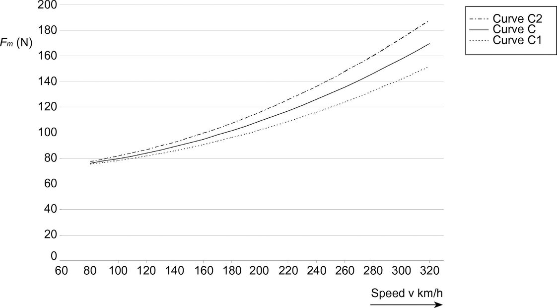
|
AC |
Curve C2 |
Fm = 0,001145 × v2 + 70 |
(N) |
|
AC |
Curve C |
Fm = 0,00097 × v2 + 70 |
(N) |
|
AC |
Curve C1 |
Fm = 0,000795 × v2 + 70 |
(N) |
For new lines and when upgrading existing lines of all categories, the curve C shall be used.
New lines may additionally permit the use of Pantographs following C1 or C2 curves. Existing lines may require the use of pantographs following curves C1 or C2; the curve applied shall be stated in the Infrastructure Register.
Figure 4.2.15.2
Mean contact force Fm for DC systems as a function of speed

|
DC |
3 kV |
Fm = 0,00097 × v2 + 110 |
(N) |
|
DC |
1,5 kV |
Fm = 0,00228 × v2 + 90 |
(N) |
4.2.16. Dynamic behaviour and quality of current collection
4.2.16.1. Requirements
The overhead contact line shall be designed in accordance with the requirements for dynamic behaviour. Contact wire uplift at the design line speed shall comply with the stipulations in Table 4.2.16.
The quality of current collection has a fundamental impact on the life of a contact wire and shall, therefore, comply with agreed and measurable parameters.
Compliance with the requirements on dynamic behaviour shall be verified in accordance with EN 50367:2006, clause 7.2 by assessment of:
|
— |
Contact wire uplift and either |
|
— |
Mean contact force Fm and standard deviation σ max or |
|
— |
Percentage of arcing |
The Contracting Entity shall declare the method to be used for verification. The values to be achieved by the chosen method are set out in Table 4.2.16.
Table 4.2.16
Requirements for dynamic behaviour and current collection quality
|
Requirement |
Category I |
Category II |
Category III |
|
Space for steady arm uplift |
2 S 0 |
||
|
Mean contact force Fm |
See 4.2.15 |
||
|
Standard deviation at maximum line speed σmax (N) |
0,3 Fm |
||
|
Percentage of arcing at maximum line speed, NQ (%) (minimum duration of arc 5ms) |
≤ 0,2 |
≤ 0,1 for AC systems ≤ 0,2 for DC systems |
≤ 0,1 |
For definitions, values and test methods refer to EN 50317:2002 and EN 50318:2002.
S 0 is the calculated, simulated or measured uplift of the contact wire at a steady arm, generated in normal operating conditions with one or more pantographs with a mean contact force Fm at the maximum line speed. When the uplift of the steady arm is physically limited due to the overhead contact line design, it is permissible for the necessary space to be reduced to 1,5 S 0 (refer to EN 50119:2001 clause 5.2.1.3).
Fm is the dynamically corrected statistical mean value of the contact force.
4.2.16.2. Conformity Assessment
4.2.16.2.1. Interoperability Constituent Overhead Contact Line
A new design of overhead contact line shall be assessed by simulation according to EN 50318:2002 and by measurement of a test section of the new design according to EN 50317:2002.
The simulations shall be made using at least two different TSI compliant (1) pantographs for the appropriate system, up to the design speed of the pantograph and the proposed Interoperability Constituent Overhead Contact Line for both a single pantograph and multiple pantographs with spacing according table 4.2.19. In order to be acceptable, the simulated current collection quality shall be within the limits of table 4.2.16 for uplift, mean contact force and standard deviation for each of the pantographs.
If the simulation results are acceptable, a site test with a representative section of the new overhead contact line shall be undertaken using one of the pantographs used in the simulation, installed on a train or locomotive producing a mean contact force at the envisaged design speed as required by clause 4.2.15 when operated on one of the overhead contact line systems. In order to be acceptable, the measured current collection quality shall be within the limits of table 4.2.16.
If all the above assessments are passed successfully, the tested overhead contact line design shall be considered to be compliant and may be used on lines where the characteristics of the design match the requirements of the line. This aspect is covered by this TSI.
4.2.16.2.2. Interoperability Constituent Pantograph
In addition to the pantograph requirements in the Rolling Stock TSI, a new design of a pantograph shall be assessed by simulation according to EN 50318:2002.
The simulations shall be made using at least two different TSI compliant (2) overhead contact lines for the appropriate system, at the design speed of the Pantograph. The simulated current collection quality shall be within the limits of table 4.2.16 for uplift, mean contact force and standard deviation for each of the overhead contact lines.
If the simulation results are acceptable, a site test shall be made using a representative section of one of the overhead contact lines used in the simulation; the interaction characteristics shall be measured in accordance with EN 50317:2002. The pantograph shall be mounted on a train or locomotive so as to produce a mean contact force as required by clause 4.2.15 for the design speed of the pantograph. The measured current collection quality shall be within the limits of table 4.2.16.
If all the assessments are passed successfully, the tested pantograph design shall be considered as compliant and can be used on various designs of rolling stock provided that the mean contact force on the rolling stock complies with the requirements of clause 4.2.16.1. This aspect is covered by the High Speed Rolling Stock TSI.
4.2.16.2.3. IC OCL in a newly installed line (Integration into a Subsystem)
If the overhead contact line to be installed on a new high-speed line is certificated as an Interoperability Constituent, measurements of the interaction parameters in accordance with EN 50317:2002 shall be used to check the correct installation. These measurements shall be carried out with an Interoperability Constituent pantograph installed on rolling stock exhibiting the mean contact force characteristics as required by clause 4.2.15 of this TSI for the envisaged design speed. The main goal of this test is to identify construction errors but not to assess the design in principle. The installed overhead contact line can be accepted if the measurement results comply with the requirements of table 4.2.16. This aspect is covered by this TSI.
4.2.16.2.4. IC Pantograph integrated into new rolling stock
When an approved interoperability constituent pantograph is to be installed on new rolling stock, testing shall be limited to the mean contact force requirements. The tests shall be carried in accordance with EN 50317:2002 or EN 50206-1:1998 (3). The tests shall be conducted in both directions of travel and at the range of nominal contact wire heights as applied for. The measured results shall follow the mean curve, plotted using at least 5 speed intervals for Class 1 trains and at least 3 speed intervals for Class 2 trains. The results shall comply with the curves throughout the speed range for the vehicle, within a range of:
|
— |
+0, –10 % for the AC curve C |
|
— |
+0 %, –10 % for the AC C1 curve (C1 is an upper limit curve) |
|
— |
+10 %, –0 % for the AC C2 curve (C2 is a lower limit curve) |
|
— |
+/– 10 % for both the DC Curves |
If the tests are passed successfully, the pantograph mounted on that particular train or locomotive can be used on TSI compliant high-speed lines. This aspect is covered by the High Speed Rolling Stock TSI.
4.2.16.2.5. Statistical calculations and simulations
The calculation of statistical values shall be appropriate to the speed of the line, and shall be carried out separately for sections in the open and in tunnels. For the purposes of simulation, the control sections shall be defined so that they are representative including features, for example tunnels, crossovers, neutral sections etc.
4.2.17. Vertical movement of the contact point
The contact point is the point of the mechanical contact between a contact strip and a contact wire.
The vertical height of the contact point above the track shall be as uniform as possible along the span length; this is essential for high-quality current collection.
The maximum difference between the highest and the lowest dynamic contact point height within one span shall be less than the values shown in Table 4.2.17.
This shall be verified by measurements according to EN 50317:2002 or simulations validated according to EN 50318:2002:
|
— |
for the maximum line speed of the overhead contact line, |
|
— |
by using the mean contact force Fm (see clause 4.2.15), |
|
— |
for the longest span length. |
This need not be verified for overlap spans or for spans over switches.
Table 4.2.17
Vertical movement of the contact point
|
|
Category I |
Category II |
Category III |
|
AC |
80 mm |
100 mm |
National rules apply |
|
DC |
80 mm |
150 mm |
National rules apply |
4.2.18. Current capacity of the overhead contact line system: AC and DC systems, trains in motion
The current capacity shall comply at least with the requirements specified for trains according to EN 50388:2005, clause 7.1. The data in EN 50149:2001 shall be used in the design process.
The thermal effects on the overhead contact line system are related to the level of current which is drawn and the time for which that current is drawn. Crosswinds have a cooling effect. The most unfavourable wind conditions on which the calculation of the current capacity shall be based shall be stipulated by the contracting entity.
The design of the overhead contact line system shall ensure that the maximum conductor temperatures specified in EN 50119:2001, annex B are not exceeded, taking account the data given in EN 50149:2001, clause 4.5, Tables 3 and 4 and the requirements of EN 50119:2001 clause 5.2.9. A design study shall be undertaken to confirm that the overhead contact line system complies with the specified requirements.
Conformity assessment shall be carried out by design review.
4.2.19. Pantograph spacing used for the design of the overhead contact line
The overhead contact line shall be designed for operation at maximum line speed with two operating adjacent pantographs having the spacing as set out in Table 4.2.19:
Table 4.2.19
Pantograph spacing
|
|
Category I |
Category II |
Category III |
|
AC systems |
200 m |
200 m |
National rules apply |
|
DC systems |
200 m |
1,5 kV: 35 m 3,0 kV: 200 m |
National rules apply |
Conformity assessment shall be carried out by verifying compliance with the requirements for dynamic behaviour defined in clause 4.2.16.
4.2.20. Current capacity, DC systems, trains at standstill
The overhead contact line of DC systems shall be designed to sustain 300 A for 1,5 kV and 200 A for 3,0 kV, per pantograph (see Annex D).
Permissible temperatures are an open point.
Without other requirements, the contact wire temperature shall not exceed the limits set out in EN 50119:2001, Annex B. The overhead contact line shall be tested using the methodology specified in EN 50367:2006, Annex A.4.1.
Conformity assessment shall be carried out in accordance with EN 50367:2006, clause 6.2.
4.2.21. Phase separation sections
The design of phase separation sections shall ensure that TSI compliant trains (see High Speed Rolling Stock TSI 2006 clause 4.2.8.3.6.2) can move from one section to an adjacent one without bridging the two phases.
Adequate means shall be provided to allow a train that is stopped within the phase separation section to be restarted. The neutral section shall be connectable to the adjacent sections by remotely controlled disconnectors. The Infrastructure Register shall contain information on the design of phase separation sections (see Annex D).
Lines of category I
Two types of designs of phase separation sections may be adopted, either:
|
— |
a phase separation design where all the pantographs of the longest TSI compliant trains are within the neutral section. The length of the neutral section shall be at least 402 m. For detailed requirements see EN 50367:2006, Annex A.1.3, or |
|
— |
a shorter phase separation with three insulated overlaps as shown in EN 50367:2006, Annex A.1.5. The overall length of this separation is less than 142 m including clearances and tolerances. |
Lines of category II and III
Upon grounds of costs or topographical constraints, it is permissible to adopt various solutions.
For category II and III lines, separation sections as specified for category I lines or a design according to Figure 4.2.21 may be adopted. In the case of Figure 4.2.21, the centre section shall be connected to the current return path, the neutral sections (d) may be formed by insulating rods or double section insulators and the dimensions shall be as follows:
D ≤ 8 m
The length of d shall be chosen in accordance with the system voltage, maximum line speed and the maximum pantograph width.
If the separation sections required for category I lines or the separation section according to Figure 4.2.21 are not used, the Infrastructure Manager shall provide adequate procedures or a design to allow for the passage of trains compliant with the High Speed Rolling Stock TSI. Where an alternative solution is proposed, it shall be demonstrated that the alternative is at least as reliable.
Figure 4.2.21
Separation Section with Insulators

Information on the design of phase separation sections shall be provided in the Infrastructure Register (see Annex D).
For design of phase separation sections, conformity assessment shall be carried out within assessment of the Energy subsystem.
4.2.22. System separation sections
4.2.22.1. General
The design of system separation sections shall ensure that TSI compliant trains (see High Speed Rolling Stock TSI 2006 clause 4.2.8.3.6.2) can move from one power supply system to an adjacent different power supply system without bridging the two systems.
There are two possibilities for the train to run through system separation sections:
|
(a) |
with pantograph raised and touching the contact wire, |
|
(b) |
with pantograph lowered and not touching the contact wire. |
The neighbouring Infrastructure Managers shall agree either (a) or (b) according to the prevailing circumstances. That choice shall be declared in the Infrastructure Register (see Annex D).
4.2.22.2. Pantographs raised
If system separation sections are traversed with pantographs raised to the contact wire, the following conditions apply:
|
1. |
the functional design of the system separation section is specified as follows:
|
|
2. |
if the line speed is higher than 250 km/h, the height of the contact wires in both systems shall be the same. |
Figure 4.2.22
Example of a system separation section
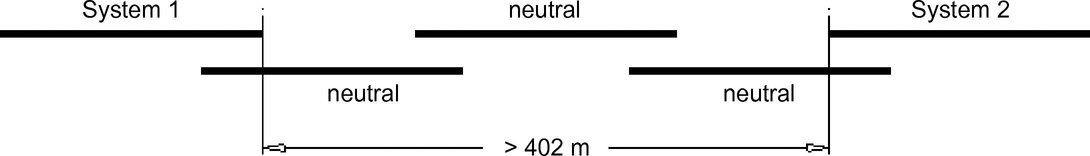
4.2.22.3. Pantographs lowered
This option shall be chosen if the conditions of operation with pantographs raised can not be met.
If a system separation section is traversed with pantographs lowered, it shall be designed so as to avoid the bridging by an unintentionally raised pantograph. Equipment shall be provided to switch off both power supply systems should a pantograph remain raised, e.g. by detection of short circuits.
For design of system separation sections, conformity assessment shall be carried out within the Energy subsystem.
4.2.23. Electrical Protection Coordination Arrangements
Electrical protection coordination design of the Energy subsystem shall comply with the requirements detailed in EN 50388:2005, clause 11. The Infrastructure Register shall contain information on protection arrangements of the overhead contact line system (see Annex D) to permit the High Speed Rolling Stock subsystem to demonstrate compatibility.
Conformity assessment shall be carried out for design and operation of substations in accordance with EN 50388:2005 clause 14.6.
4.2.24. Effects of DC operation on AC systems
The fixed installations shall be designed so that they are immune to low value DC currents flowing out of the DC power supply system into the AC power supply system. Immunity from DC current of Open point Amps is required.
4.2.25. Harmonics and Dynamic Effects
The High Speed Energy subsystem shall withstand overvoltages generated by rolling stock harmonics up to the limits stated in EN 50388:2005 clause 10.4. Conformity assessment shall consist of a compatibility study that demonstrates that the subsystem element can withstand harmonics up to the defined limits according to EN 50388:2005, clause 10. Conformity assessment shall be conducted according to EN 50388:2005 clause 10.
4.3. Functional and technical specifications for the interfaces
From the standpoint of technical compatibility, the interfaces of the Energy subsystem with the other subsystems are listed by subsystem below. The interfaces are listed in subsystem order as follows: Rolling Stock, Infrastructure, Control Command Signalling, Operations.
4.3.1. High Speed Rolling stock subsystem
|
Energy Subsystem Parameter |
High Speed Energy TSI Clause |
High Speed Rolling Stock TSI Clause |
Rolling Stock Subsystem Parameter |
||
|
Voltage and frequency |
4.2.2 |
4.2.8.3.1.1 |
Energy Supply |
||
|
System performance & installed power on a line |
4.2.3 |
4.2.8.3.2 |
Maximum Power And Maximum Current That Is Permissible To Draw From The Catenary |
||
|
Power factor |
4.2.3 |
4.2.8.3.3 |
Power Factor |
||
|
Regenerative braking |
|
|
|
||
|
4.2.4 |
4.2.8.3.1.2 and |
Energy Recuperation |
||
|
4.2.4 |
4.2.4.3 |
Brake System Requirements |
||
|
External Electromagnetic Compatibility (4) |
4.2.6 |
4.2.6.6 |
Exterior Electromagnetic Interference |
||
|
Overhead Contact Line |
|
|
|
||
|
4.2.9.1 |
4.2.8.3.6.4 and 4.2.8.3.8.4 |
Pantograph Lowering, Detection of Contact Strip Breakage |
||
|
Overhead Contact Line |
|
|
|
||
|
4.2.9.2 |
4.2.3.9 |
Kinematic Gauge |
||
|
4.2.8.3.6.9 |
Height of Pantographs |
||||
|
4.2.8.3.7.2 |
Pantograph Head Geometry |
||||
|
4.2.8.3.8.2 |
Contact Strip Geometry |
||||
|
4.2.8.3.7.4 |
Working Range of Pantographs |
||||
|
Compliance of the overhead contact line system with infrastructure gauge |
4.2.10 |
4.2.3.1 |
Kinematic Gauge |
||
|
4.2.8.3.7.2 |
Pantograph Head Geometry |
||||
|
Contact wire material |
4.2.11 |
4.2.8.3.8.3 |
Contact Strip Material |
||
|
Overhead contact line system dynamics |
|
|
|
||
|
4.2.14 |
4.2.8.3.7.3 |
Pantograph Static Contact Force |
||
|
4.2.15 |
4.2.8.3.6.1 |
Adjustment of Pantograph Mean Contact Force |
||
|
4.2.16 |
4.2.8.3.6.2, |
Arrangement of Pantographs |
||
|
4.2.8.3.6.5 |
Quality of Current Collection |
||||
|
4.2.17 |
4.2.8.3.6.1 |
Adjustment of Pantograph Mean Contact Force |
||
|
Contact wire current capacity |
|
|
|
||
|
4.2.18 |
4.2.8.3.2 |
Maximum Power And Maximum Current That Is Permissible To Draw From The Catenary |
||
|
4.2.20 |
4.2.8.3.2 |
|||
|
Pantograph Spacing |
|
|
|
||
|
4.2.19 |
4.2.8.3.6.2 |
Arrangement of Pantographs |
||
|
4.2.21, 4.2.22 |
4.2.8.3.6.2 |
Arrangement of Pantographs |
||
|
Phase Separation Sections, Power Control |
4.2.21 |
4.2.8.3.6.7 |
Running Through Phase Separation Sections |
||
|
System Separation Sections, Power Control |
4.2.22 |
4.2.8.3.6.8 |
Running Through System Separation Sections |
||
|
Electrical Protection Coordination |
4.2.23 |
4.2.8.3.6.6 |
Electrical Protection Coordination |
||
|
Effects of DC operation on AC system (Open Point) |
4.2.24 |
4.2.8.3.4.2 |
Effects of DC content in AC supply |
||
|
Harmonics and Dynamic Effects |
4.2.25 |
4.2.8.3.4.1 |
Harmonic Characteristics and Related Over-Voltages on the OHL |
||
|
High visibility clothing |
4.7.5 |
4.2.7.4.1.1 |
Head lights |
4.3.2. High Speed Infrastructure subsystem
|
Energy Subsystem Parameter |
Reference High Speed Energy TSI |
Reference High Speed Infrastructure TSI |
Infrastructure Subsystem Parameter |
|
Compliance of the Overhead Contact Line system with infrastructure gauges |
4.2.10 |
4.2.3 |
Minimum Infrastructure Gauges |
|
Current Return Circuit |
4.7.3 |
4.2.18 |
Electrical Characteristics |
4.3.3. High Speed Control-Command and Signalling subsystem
The interface for power control at Phase and System Separation Sections is an interface between the Energy and Rolling Stock subsystems. However it is effected via the Control Command Signalling subsystem; consequently the interface is specified in the Control Command Signalling TSI and the Rolling Stock TSI.
Since the harmonic currents generated by rolling stock affect the Control-Command and Signalling subsystem through the Energy subsystem, this subject is dealt within the Control-Command and Signalling subsystem (see High Speed Control Command and Signalling TSI Clause 4.2.12.2 and Annex A index A6). No conformity assessment is required by the Energy subsystem.
4.3.4. High Speed Traffic Operations and Management
|
Energy Subsystem Parameter |
Reference High Speed Energy TSI |
Reference High Speed Traffic Operations and Management TSI |
High Speed Traffic Operations & Management Parameter |
|
Management of power supply in case of danger |
4.4.1 |
4.2.1.2.2.2 |
Modified elements |
|
4.2.1.2.2.3 |
Informing the driver in real time |
||
|
Execution of works |
4.4.2 |
2.2.1 |
Cross-Border Worksites |
|
4.2.1.2.2.2 |
Modified elements |
||
|
4.2.1.2.2.3 |
Informing the driver in real time |
The Infrastructure Manager is required to have systems in place to communicate with the Railway Undertakings.
4.3.5. Safety in Railway Tunnels
|
Energy Subsystem Parameter |
Reference High Speed Energy TSI |
Reference Safety in Railway Tunnels TSI |
Safety in Railway Tunnels Parameter |
|
Continuity of power supply in case of disturbances |
4.2.7 |
4.2.3.1 |
Segmentation of overhead line or conductor rails |
The sectioning of the power supply in a tunnel shall be designed in accordance with the overall strategy for evacuation from the tunnel in question.
4.4. Operating rules
In light of the essential requirements in chapter 3, the operating rules specific to the Energy subsystem concerned by this TSI are as follows:
4.4.1. Management of power supply in case of danger
Procedures shall be implemented by the Infrastructure Manager to manage the power supply adequately in an emergency. Railway undertakings operating and companies working on the line shall be given notice of the temporary measures, of their geographic location, their nature and the means of signalling. The responsibility for earthing shall be defined in the emergency plan to be written by the Infrastructure Manager.
Conformity assessment shall be carried out by checking the existence of communications channels, instructions, procedures and devices to be used in emergency.
4.4.2. Execution of works
In certain situations involving pre-planned works, it may be necessary to temporarily suspend the specifications of the energy subsystem and its interoperability constituents defined in chapters 4 and 5 of the TSI. In this case, the Infrastructure Manager shall define the appropriate exceptional operating conditions needed to ensure safety.
The following general provisions apply:
|
— |
the exceptional operating conditions not complying with the TSIs shall be temporary and planned, |
|
— |
railway undertakings operating and companies working on the line shall be given notice of these temporary exceptions, of their geographic location, their nature and the means of signalling |
Principles for agreement between neighbouring Infrastructure Managers regarding worksites in cross-border sections are stated in High Speed OPE TSI clause 2.2.1.
4.4.3. Day-to-day management of power supply
It is permissible for the Infrastructure Manager to vary the maximum permissible train current according to the time of day and/or power supply condition. The Railway Undertakings using the line shall be given notice of these variations, of their geographic location, their nature and the means of signalling (see Annex D).
4.5. Maintenance of power supply and overhead contact line system
4.5.1. Manufacturer’s Responsibility
The manufacturer shall provide operation limits for all design parameters for the overhead contact line, which can change during operation. For example, data for permissible contact wire wear and permissible stagger tolerance shall be provided.
4.5.2. Infrastructure Manager’s Responsibility
The Infrastructure Manager shall uphold the specified characteristics of the power supply system (including substations and posts) and the overhead contact line during their lifetime.
A maintenance plan shall be drawn up by the Infrastructure Manager to ensure that the specified characteristics of the Energy subsystem required to assure interoperability are upheld within the specified limits. The maintenance plan shall contain in particular the description of professional competences for the staff and of the personal protective safety equipment to be used by it.
The Infrastructure Manager shall devise and implement methods for reporting information on safety-critical defects and frequent system failures to the national safety authority.
Maintenance procedures shall not downgrade safety provisions such as the continuity of return current circuit, limitation of overvoltages and detection of short circuits.
4.6. Professional competences
The professional competences required for the operation of the High Speed Energy subsystem are covered by the High Speed Traffic Operation and Management TSI.
The competence requirements for the maintenance of the Energy subsystem shall be detailed in the maintenance plan (see clause 4.5.2).
4.7. Health and safety conditions
4.7.1. Protective provisions of substations and posts
Electrical safety of the traction power supply systems shall be achieved by designing and testing these installations according to EN 50122-1:1997, clauses 8 (excluding EN 50179) and 9.1. Substations and switching posts shall be barred against unauthorised access.
The earthing of substations and posts shall be integrated into the general earthing system along the route to comply with the requirements for protection against electric shock as specified in EN 50122-1:1997, clauses 8 (excluding EN 50179) and 9.1.
For each installation, it shall be demonstrated that return current circuits and earthing conductors are adequate by design review. It shall be demonstrated that the provisions for protection against electric shock and rail potential, as designed, have been installed.
Conformity assessment shall be carried out within the assessment of the Energy subsystem.
4.7.2. Protective provisions of overhead contact line system
Electrical safety of the overhead contact line system and protection against electric shock shall be achieved by compliance with EN 50119:2001 clause 5.1.2 and EN 50122-1:1997 clauses 4.1, 4.2, 5.1 (excluding 5.1.2.5), 5.2 and 7.
The earthing provisions of the overhead contact line system shall be integrated into the general earthing system along the route. For each installation it shall be demonstrated that earthing conductors are adequate by design review. It shall be demonstrated that the provisions for protection against electric shock and rail potential, as designed, have been installed.
Conformity assessment shall be carried out within the assessment of the energy subsystem.
4.7.3. Protective provisions of current return circuit
Electrical safety and functionality of the current return circuit shall be achieved by designing these installations according to EN 50122-1:1997, clause 7, 9.2, 9.3, 9.4, 9.5, 9.6 (excluding EN 50179).
For each installation it shall be demonstrated that return current circuits are adequate by design review. It shall be demonstrated that the provisions for protection against electric shock and rail potential, as designed, have been installed.
Conformity assessment shall be carried out within the assessment of the energy subsystem.
4.7.4. Other general requirements
In addition to clauses 4.7.1 to 4.7.3, and the requirements specified in the maintenance plan (see clause 4.5.2), precautions shall be taken to ensure health and safety for maintenance and operations staff, in accordance with the European regulations and the national regulations that are compatible with European legislation.
4.7.5. High Visibility Clothing
Staff engaged in the maintenance of the High Speed Energy subsystem, when working on or near the track, shall wear reflective clothes, which bear the EC mark (and therefore satisfy the provisions of Directive 89/686/EEC of 21 December 1989 on the approximation of the laws of the Member States relating to personal protective equipment).
4.8. Infrastructure and Rolling Stock Registers
4.8.1. Infrastructure Register
Annex D of this TSI indicates which information concerning the Energy subsystem shall be included in the Infrastructure Register. In all cases when any part or whole of a High Speed Energy subsystem is made compliant with this TSI, an entry shall be made in the Infrastructure Register as indicated in Annex D and the relevant clause in chapters 4 and 7.4 (specific cases).
4.8.2. Rolling Stock Register
Annex E of this TSI indicates which information concerning the Energy subsystem shall be included in the Rolling Stock Register.
5. INTEROPERABILITY CONSTITUENTS
5.1. Definitions
According to Article 2(d) of Directive 96/48/EC as modified by Directive 2004/50/EC, interoperability constituents are: any elementary component, group of components, subassembly or complete assembly of equipment incorporated or intended to be incorporated into a subsystem, upon which the interoperability of the trans-European high-speed rail system depends either directly or indirectly.
5.2. Innovative solutions
As stated in section 4.1 of this TSI, innovative solutions may require new specification and/or new assessment methods. These specifications and assessment methods shall be developed by the process described in sections 6.1.2.3 (and 6.2.2.2).
5.3. List of interoperability constituents
The interoperability constituents are covered by the relevant provisions of Directive 96/48/EC as modified by Directive 2004/50/EC and as listed below so far as the Energy subsystem is concerned.
|
Overhead Contact Line: |
The Interoperability Constituent Overhead Contact Line consists of the components listed below to be installed within an Energy subsystem, and the associated design & configuration rules. The components of an overhead contact line are an arrangement of wires suspended over the railway line for supplying electricity to electric trains, together with associated fittings, in-line insulators and other attachments including feeders and jumpers. It is placed above the upper limit of the vehicle gauge, supplying vehicles with electrical energy through roof-mounted current collection equipment known as pantographs. In the case of high-speed rail systems, an overhead contact line with catenary suspension is applied where the contact wire(s) is/are suspended from one or more longitudinal catenaries. The supporting components such as cantilevers, masts and foundations, return conductors, auto-transformer feeders, switches and other insulators are not part of the interoperability constituent overhead contact line. They are covered by subsystem requirements so far as interoperability is concerned. |
5.4. Constituents’ performances and specifications
5.4.1. Overhead contact line
5.4.1.1. Overall design
The design of the overhead contact line shall comply with clause 4.2.9.1
5.4.1.2. Geometry
The design of the overhead contact line shall comply with the technical specifications given in clauses 4.2.9.2, 4.2.10 and 4.2.12.
5.4.1.3. Current capacity
The current capacity shall comply with the requirements set out in clause 4.2.18.
5.4.1.4. Contact wire material
Contact wire materials shall comply with clause 4.2.11.
5.4.1.5. Current at standstill
For DC systems, the overhead contact line shall be designed for the requirements set out in clause 4.2.20.
5.4.1.6. Wave propagation speed
The wave propagation speed of the contact wire shall comply with the requirements of 4.2.12.
5.4.1.7. Design for pantograph spacing
The overhead contact line shall be designed for a pantograph spacing as specified in clause 4.2.19.
5.4.1.8. Mean contact force
The overhead contact line shall be designed by using the mean contact force Fm stipulated in clause 4.2.15.
5.4.1.9. Dynamic behaviour and quality of current collection
The overhead contact line shall be designed in accordance with the requirements for dynamic behaviour. Requirements are set out in clause 4.2.16.
Compliance with the requirements shall be demonstrated according to clause 4.2.16.2.1.
5.4.1.10. Vertical movement of contact point
The contact point is the point of the mechanical contact between a contact strip and a contact wire. The requirements are specified in clause 4.2.17.
5.4.1.11. Space for uplift
The overhead contact line shall be designed providing the required space for uplift as set out in clause 4.2.16.
6. ASSESSMENT OF CONFORMITY AND/OR SUITABILITY FOR USE
6.1. Interoperability constituents
6.1.1. Assessment procedures and modules
The assessment procedure for conformity of interoperability constituents as defined in chapter 5 of this TSI shall be carried out by application of modules as specified in Annex A to this TSI.
If the manufacturer can demonstrate that tests or verification for previous applications remain valid for the new applications, then the Notified Body shall take them into account in the conformity assessment.
Assessment procedures for conformity of the interoperability constituent overhead contact line as defined in chapter 5 of this TSI, are indicated in Annex B, Table B.1 to this TSI.
As far as required by the modules specified in Annex A to this TSI, the assessment of conformity of an interoperability constituent shall be conducted by the Notified Body, appointed by the manufacturer or his authorised representative established within the Community.
The manufacturer of an interoperability constituent or his authorised representative established within the Community shall draw up an EC declaration of conformity in accordance with Article 13(1) of and Annex IV, chapter 3 to Directive 96/48/EC as modified by Directive 2004/50/EC before placing the interoperability constituent on the market. An EC declaration of suitability for use is not required for interoperability constituents of the Energy subsystem.
6.1.2. Application of modules
6.1.2.1. General
For the conformity assessment procedure of an interoperability constituent of the Energy subsystem, the manufacturer or his authorised representative established within the Community may choose either:
|
— |
the type-examination procedure (module B) indicated in Annex A.1 to this TSI for the design and development phase in combination with the conformity to type procedure (module C) indicated in Annex A.1 to this TSI for the production phase, or |
|
— |
the full quality management system with design examination procedure (module H2) indicated in Annex A.1 to this TSI for all phases. |
These assessment procedures are defined in Annex A to this TSI.
The module H2 may only be chosen where the manufacturer operates a quality management system for design, production, final product inspection and testing, approved and surveyed by a Notified Body.
The conformity assessment shall cover the phases and characteristics as indicated by X in the Table B.1 of Annex B to this TSI.
6.1.2.2. Existing solutions for Interoperability Constituents
If an existing solution for an interoperability constituent is already on the European market before this TSI enters into force, then the following process applies.
The manufacturer shall demonstrate that tests and verification of ICs have been considered successful for previous applications under comparable conditions. In this case these assessments shall remain valid in the new application.
In this case, the type can be considered as already approved and an assessment of the type is not necessary.
In accordance with assessment procedures for the different ICs, the manufacturer or its authorised representative established within the Community shall apply either:
|
— |
the internal design control with production verification procedure (module A1), |
|
— |
or the full quality management system procedure (module H1). |
If it is not possible to demonstrate that the solution is positively proven in the past, the Section 6.1.2.1 applies.
6.1.2.3. Innovative solutions for Interoperability Constituents
When a solution proposed to be an Interoperability Constituent is innovative, as defined in the section 5.2, the manufacturer shall state the deviation from the relevant section of the TSI and apply for assessment of conformity or suitability for use of the solution. The European Railway Agency shall finalise the appropriate functional and interface specifications of the constituents and develop the assessment methods.
The appropriate functional and interface specifications and the assessment methods shall be incorporated in the TSI by the revision process. As soon as these documents are published, the assessment procedure of the interoperability constituents may be chosen by the manufacturer or his authorised representative established within the Community, as specified in the section 6.1.2.1
After entry into force of a decision of the Commission, taken in accordance with Article 21(2) of Directive 96/48/EC as modified by Directive 2004/50/EC, the innovative solution may be used before being incorporated into the TSI.
6.2. Energy subsystem
6.2.1. Assessment procedures and modules
At the request of the Contracting Entity or its authorised representative established within the Community, the Notified Body carries out the EC verification in accordance with Article 18(1) of and Annex VI to Directive 96/48/EC as modified by Directive 2004/50/EC, and in accordance with the provisions of the relevant modules as specified in Annex A to this TSI.
If the Contracting Entity can demonstrate that tests or verification for previous applications remain valid for the new applications, the Notified Body shall take them into account in the conformity assessment
Assessment procedures for the EC verification of the Energy subsystem are indicated in Annex C, Table C.1, to this TSI.
As far as specified in this TSI, the EC verification of the Energy subsystem shall take account of its interfaces with other subsystems of the trans-European high-speed rail system.
The Contracting Entity shall draw up the EC declaration of verification for the Energy subsystem in accordance with Article 18(1) of and Annex V to Directive 96/48/EC as modified by Directive 2004/50/EC.
6.2.2. Application of modules
6.2.2.1. General
For the assessment procedure of the Energy subsystem the Contracting Entity or its authorised representative established within the Community may choose either:
|
— |
the unit verification procedure (module SG) indicated in Annex A.2 to this TSI, or |
|
— |
the full quality management system with design examination procedure (module SH2) indicated in Annex A.2 to this TSI. |
The module SH2 may be chosen only where all activities contributing to the subsystem project to be verified (design, manufacturing, assembling, installation) are subject to a quality management system for design, production, final product inspection and testing, approved and surveyed by a Notified Body.
The assessment shall cover the phases and characteristics as indicated in Table C.1 of Annex C to this TSI.
6.2.2.2. Innovative solutions
When an Energy subsystem includes an innovative solution, as defined in section 4.1, the contracting entity shall state the deviation from the relevant section of the TSI and apply for assessment of conformity.
The European Railway Agency shall finalise the appropriate functional and interface specifications of this solution and develop the assessment methods.
The appropriate functional and interface specifications and the assessment methods shall be incorporated in the TSI by the revision process. As soon as these documents are published, the assessment procedure for the subsystem may be chosen by the manufacturer or the contracting entity or his authorised representative established within the Community, as specified in the section 6.2.2.1.
After entry into force of a decision of the Commission, taken in accordance with Article 21(2) of Directive 96/48/EC as modified by Directive 2004/50/EC, the innovative solution may be used before being incorporated into the TSI.
6.2.3. Assessment of maintenance
According to Article 18.3 of Directive 96/48/EC as modified by Directive 2004/50/EC, the Notified Body shall compile the technical file, which includes the maintenance plan.
The Notified Body shall verify only the completeness of the maintenance plan.
The conformity assessment of maintenance is the responsibility of each of the Member State(s) concerned.
6.3. Validity of certificates issued against the previous published version of the TSI
Certificates of conformity already issued against the previous published version of this TSI continue to remain valid in the following cases:
|
— |
issued at any stage for interoperability constituents produced or in production, but not yet integrated in a subsystem |
|
— |
issued at the design stage for interoperability constituents not yet produced |
|
— |
issued at any stage for subsystems that have been put into service |
|
— |
issued at the design stage for subsystems not yet put into service |
6.4. Interoperable constituents not holding an EC Declaration
6.4.1. General
For a limited period of time, known as the ‘transition period’, interoperability constituents not holding an EC Declaration of Conformity or Suitability for Use may exceptionally be incorporated into subsystems, on the condition that the provisions described in this section are met.
6.4.2. The transition period
The transition period shall commence from the entry into force of this TSI and shall last for six years.
Once the transition period has ended, and with the exceptions allowed under section 6.4.3.3 below, interoperability constituents shall be covered by the required EC declaration of conformity and/or suitability for use before being incorporated into the subsystem;
6.4.3. The certification of subsystems containing non-certified interoperability constituents during the transition period
6.4.3.1. Conditions
During the transition period a Notified Body is permitted to issue a certificate of conformity for a subsystem, even if some of the interoperability constituents incorporated within the subsystem are not covered by the relevant EC declarations of conformity and/or suitability for use according to this TSI, if the following three criteria are complied with:
|
— |
the conformity of the subsystem has been checked in relation to the requirements defined in chapter 4 of this TSI by the Notified Body, and |
|
— |
through carrying out additional assessments the Notified Body confirms that the conformity and/or the suitability for use of the interoperability constituents is in accordance with the requirements of chapter 5, and |
|
— |
the interoperability constituents, which are not covered by the relevant EC declaration of conformity and/or suitability for use, shall have been used in a subsystem already put in service in at least one of the Member States before the entry in force of this TSI. |
EC Declarations of conformity and/or suitability for use shall not be drawn up for the interoperability constituents assessed in this manner.
6.4.3.2. Notification
|
— |
the certificate of conformity of the subsystem shall indicate clearly which interoperability constituents have been assessed by the Notified Body as part of the subsystem verification. |
|
— |
the EC declaration of verification of the subsystem shall indicate clearly:
|
6.4.3.3. Lifecycle Implementation
The production or upgrade/renewal of the subsystem concerned must be completed within the six years of the transition period. Concerning the subsystem lifecycle:
|
— |
During the transition period and |
|
— |
under the responsibility of the body having issued the declaration of EC verification of the subsystem |
the interoperability constituents which do not hold an EC declaration of conformity and/suitability for use and are of the same type built by the same manufacturer are permitted to be used for maintenance related replacements and as spare parts for the subsystem.
After the transition period has ended and
|
— |
until the subsystem is upgraded, renewed or replaced and |
|
— |
under the responsibility of the body having issued the declaration of EC verification of the subsystem |
the interoperability constituents which do not hold an EC declaration of conformity and/or suitability for use and are of the same type built by the same manufacturer may continue to be used for maintenance related replacements.
6.4.4. Monitoring arrangements
During the transition period Member States shall monitor:
|
— |
The number and type of interoperability constituents introduced on the market within their own State; |
|
— |
Ensure that, where a subsystem is presented for authorisation, reasons for non-certification of the interoperability constituent by the manufacturer are identified; |
|
— |
Notify, to the Commission and to the other Member States, the details of the non-certified IC and the reasons for non-certification. |
7. IMPLEMENTATION OF THE ENERGY TSI
7.1. Application of this TSI to new high-speed lines being put into service
Chapters 4 to 6 and any specific provisions in paragraph 7.4 below apply in full to the lines coming within the geographical scope of this TSI (cf. paragraph 1.2) which will be put into service after this TSI enters into force.
7.2. Application of this TSI to high-speed lines already in service
7.2.1. Introduction
In respect of infrastructure installations already in operation, this TSI applies to sections of line being upgraded or renewed under the conditions specified in Article 14.3 of Directive 96/48/EC as modified by Directive 2004/50/EC. In this particular context, it relates fundamentally to the application of a migration strategy which enables an economically justifiable adaptation of existing Energy installations to be made.
Whilst the TSI can be fully applied to new installations, implementation on existing lines may require modifications of existing equipment. The degree of modification necessary will depend on the extent of conformity of the existing equipment. The following principles apply in the case of the High Speed Energy TSI, without prejudice to clause 7.4 (Specific cases). When the Member State requires a new putting into service, the Contracting Entity shall define the practical measures and different phases which are necessary to achieve the required levels of performance. These phases may include transition periods for placing into service with reduced levels of performance.
This TSI shall not apply to existing energy subsystems of the high speed network as long as they are not renewed or upgraded.
7.2.2. Classification of works
Taking into account the foreseeable life span of the different parts of the energy subsystem, the list of those parts in descending order of difficulty of modification is as follows:
|
— |
Parameters and specifications concerning the complete subsystem |
|
— |
Parameters concerning the mechanical parts of the overhead line |
|
— |
Parameters concerning the power supply |
|
— |
Parameters concerning the contact wire |
|
— |
Parameters related to other directives, to operational and maintenance |
Table 7.2 sets out the parameters, and the categories that they fall into.
7.2.3. Parameters and specifications concerning the complete subsystem
The elements concerning the complete system involve the most constraints, since more often than not they can and shall only be modified when complete restructuring work of the complete Energy subsystem of the line (re-electrification) is carried out. Clause 4.2.10 is also linked to the modifications of the gauge of the line section (structures, tunnels, etc.).
7.2.4. Parameters concerning the mechanical parts of the OCL and the power supply
These parameters are less critical as regards partial modifications, either because they can be gradually modified in areas of limited geographical extent or because certain components can be modified independently of the subsystem of which they form part.
They will be brought into conformity in the course of major overhead contact line upgrading projects intended to improve line performance.
It is possible to gradually replace all or part of the mechanical Overhead Contact Line elements by elements in conformity with the TSI. In such cases, account must be taken of the fact that each of these elements taken in isolation does not make it possible on its own to ensure the conformity of the whole: the conformity of a subsystem or Interoperability Constituent can only be stated globally, i.e. when all the elements have been brought into conformity with the TSI.
Intermediate stages may, in this case, prove necessary in order to maintain the compatibility of the overhead contact line with the provisions of other subsystems (control-command and signalling, infrastructure), as well as with the movement of trains not covered by TSIs.
7.2.5. Parameters concerning the contact wire
Conformity is required each time a new contact wire is installed in an overhead contact line.
7.2.6. Parameters related to other directives, to operational and maintenance
These parameters have to be fulfilled for each upgrade and renewal.
7.2.7. Scope of application
Each time there is a cross in column 3 or 4, the corresponding requirement shall also be applied when applying clause 7.2.3 (complete sub-system, column 2).
When there is a cross in column 5, the corresponding requirement shall also be applied when applying clauses 7.2.3 (complete sub-system (column 2)) or 7.2.4 (mechanical parts of the OCL (columns 3) or power supply (column 4)).
NB: in both these instances, it is not a requirement to change physical components if compliance with the TSI can be demonstrated.
Table 7.2.7
Application of the TSI when upgrading/renewing lines already in service
|
ENE TSI Clause Number |
Complete Subsystem |
Mechanical parts of OCL |
Power Supply |
Contact Wire |
Other directives, Operational, Maintenance |
|
Column 1 |
Column 2 |
Column 3 |
Column 4 |
Column 5 |
Column 6 |
|
4.2.2 |
X |
|
|
|
|
|
4.2.3 |
|
|
X |
|
|
|
4.2.4 |
|
|
X |
|
|
|
4.2.5 |
|
|
|
|
X |
|
4.2.6 |
|
|
|
|
X |
|
4.2.7 |
|
|
X |
|
|
|
4.2.8 |
|
|
|
|
X |
|
4.2.9 |
|
X |
|
|
|
|
4.2.10 |
|
X |
|
|
|
|
4.2.11 |
|
|
|
X |
|
|
4.2.12 |
|
|
|
X |
|
|
4.2.14 |
|
X |
|
|
|
|
4.2.15 |
|
X |
|
|
|
|
4.2.16 |
|
X |
|
|
|
|
4.2.17 |
|
X |
|
|
|
|
4.2.18 |
|
X |
|
|
|
|
4.2.19 |
|
X |
|
|
|
|
4.2.20 |
|
X |
|
|
|
|
4.2.21 |
|
X |
|
|
|
|
4.2.22 |
|
X |
|
|
|
|
4.2.23 |
|
|
X |
|
|
|
4.2.24 |
|
|
X |
|
|
|
4.2.25 |
|
|
X |
|
|
|
4.7.1 |
|
|
X |
|
|
|
4.7.2 |
|
X |
|
|
|
|
4.7.3 |
|
|
X |
|
|
|
4.7.4 |
|
|
|
|
X |
|
4.8 |
|
|
|
|
X |
7.3. TSI Revision
In conformity with article 6(3) of Directive 96/48/EC as modified by Directive 2004/50/EC, the Agency shall be responsible for preparing the review and updating of TSIs and making appropriate recommendations to the Committee referred to in Article 21 of this Directive in order to take account of developments in technology or social requirements. In addition, the progressive adoption and revision of other TSIs may also impact this TSI. Proposed changes to this TSI shall be subject to rigorous review and updated TSIs will be published on an indicative periodic basis of 3 years.
The Agency shall be notified of any innovative solutions being considered by manufacturers or contracting entities according to section 6.1.2.3 or 6.2.2.2, or by Notified Bodies when the manufacturer or contracting entity failed to do so in order to determine its future inclusion within the TSI.
Then the Agency shall proceed according to section 6.1.2.3 or 6.2.2.2.
7.4. Specific cases
The following special provisions are authorised specific cases. These specific cases are classified according to two categories: the provisions apply either permanently (‘P’ cases), or temporarily (‘T’ cases). For temporary cases, it is recommended that the target system is reached either by 2010 (cases ‘T1’), an objective set in Decision No 1692/96/EC of the European Parliament and of the Council of 23 July 1996 on Community guidelines for the development of the trans-European transport network or in any subsequent update to the same Decision, or by 2020 (cases ‘T2’).
7.4.1. Particular features on the Austrian network
(P case)
Category II and III lines
The investment of changing the overhead contact line on category II and III lines and in stations to meet the requirements of the 1 600 mm Euro pantograph is prohibitive. Trains traversing these lines will have to be provided with secondary 1 950 mm pantographs for medium-speed operation up to 230 km/h so that the overhead contact line on these parts of the trans-European network will not have to be prepared for the operation of the Euro pantograph. In these areas a maximum lateral deviation of contact wire of 550 mm related to the vertical on the track centre line under action of cross wind is permissible. Future studies concerning category II and III lines should take into account the Euro pantograph to demonstrate the relevance of the choices made.
Category III lines (T1 case)
To comply with the requirements on mean useful voltage and installed power additional substations are necessary. Installation is planned until 2010.
7.4.2. Particular features on the Belgian network
(T1 case)
Existing category I lines
On existing category I lines the phase separation sections are not compatible with the requirement of pantograph spacing between three pantographs of more than 143 m. Between existing category I lines and category II lines there is no automatic control to trigger the opening of the main circuit breaker on the traction vehicles.
Both items will be modified.
Category II and III lines
On some line sections, under bridges, the contact wire height does not meet the TSI minimum requirements and needs to be modified. Dates are open.
7.4.3. Particular features on the German network
(P case)
The investment of changing the overhead contact line on category II and III lines and in stations to meet the requirements of the 1 600 mm Euro pantograph is prohibitive. Trains traversing these lines shall be provided with secondary 1 950 mm pantographs for medium-speed operation up to 230 km/h so that the overhead contact line on these parts of the trans-European network need not to be prepared for the operation of the Euro pantograph. In these areas a maximum lateral contact wire position of 550 mm is permissible related to the vertical on the track centre line under action of crosswind. Future studies concerning category II and III lines should take into account the Euro pantograph to demonstrate the relevance of the choices made.
7.4.4. Particular features on the Spanish network
(P case)
On some category II and III lines and in stations the 1 600 mm Europantograph is not permitted. Trains traversing these lines shall be provided with secondary 1 950 mm pantographs for medium-speed operation up to 230 km/h.
The investment of changing the overhead contact line on category II and III lines and in stations to meet the requirements of the 1 600 mm Euro pantograph is prohibitive. Trains traversing these lines shall be provided with secondary 1 950 mm pantographs for medium-speed operation up to 230 km/h so that the overhead contact lines on these parts of the trans-European network needs not be prepared for the operation of the Euro pantograph. In these areas a maximum lateral contact wire position of 550 mm related to the vertical on the track centre line is permissible under action of crosswind. Future studies concerning category II and III lines shall take into account the Euro pantograph to demonstrate the relevance of the choices made.
The nominal contact wire height will be 5,60 m on some sections of future category I lines in Spain, particularly in case of the future high-speed line between Barcelona and Perpignan. This would also concern France between the Spanish border and Perpignan if required by both governments.
On existing high-speed lines, the phase separation sections are not compatible with the High Speed Rolling Stock TSI compliant pantograph arrangement (see High Speed Rolling Stock TSI clause 4.2.8.3.6.2). On these existing category I lines, the investment of changing these existing separation sections is very high. Consequently, if there is an incompatibility between a High Speed Rolling Stock TSI compliant train and a separation section, special operating conditions will be proposed by the Infrastructure Manager. Existing non-compliant separation sections will be upgraded during important adaptations.
7.4.5. Particular features on the French network
(P case)
Category I lines
On existing high-speed lines, the phase separation sections are not compatible with the High Speed Rolling Stock TSI compliant pantograph arrangement (see High Speed Rolling Stock TSI clause 4.2.8.3.6.2). On these existing category I lines, the investment of changing these existing separation sections is very high. Consequently, if there is an incompatibility between a High Speed Rolling Stock TSI compliant train and a separation section, special operating conditions will be proposed by the Infrastructure Manager. Existing non-compliant separation sections will be upgraded during important adaptations.
Category I lines (T2 case)
On the specific high-speed line Paris to Lyon, a modification of the overhead contact line is necessary to provide for the permissible uplift without uplift stops installed in the pantographs. As a consequence, trains not equipped with uplift stops on board are not permitted to run on this line.
Category II and III lines (T2 case)
For DC lines, the cross-section of contact wires is not sufficient to comply with the TSI requirements for current at standstill in stations or in areas where trains are pre-heated.
On the existing High Speed Line Paris-Tours, a 1,5 kV DC section (about 20 km) is operated in the vicinity of 260 km/h. The conversion of this section has not been yet scheduled.
The existing DC line Bordeaux to Spain (Irun) is operated with a 1 950 mm DC collector head. To operate this line with a compliant 1 600 mm Euro collector head, the overhead line has to be upgraded accordingly.
7.4.6. Particular features on the British network
The railway infrastructure within Great Britain was historically built to a smaller gauge than the other railways of Europe. It is uneconomic or impracticable to increase the gauge, and therefore the target gauge for Great Britain will be the UK1 issue 2 (see High Speed Infrastructure TSI).
(P Case)
Contact wire height
Variable contact wire height and gradient will be retained on electrified lines in Categories II and III. The nominal wire height adopted in future on upgraded lines in the Great Britain will not be less than 4 700 mm. However where constraints require it, the minimum permissible wire height is 4 140 mm, sufficient to allow the passage of electric trains built to UK1B gauge.
The contact wire height on the Continental Main Line, (the interface between Network Rail, the Channel Tunnel Rail Link, and Eurotunnel) the contact wire height varies between 5 935 mm and 5 870 mm.
Contact wire lateral deviation under the action of cross wind.
On existing Category II and III lines, the permissible lateral deviation of the contact wire in relation to the track centre line under the action of crosswinds shall be 400 mm at a wire height of ≤ 4 700 mm. For wire heights above 4 700 mm, this value shall decrease by 0,040 × (wire height (mm) – 4 700) mm for wire heights above 4 700 mm.
Peak Contact Force at Discrete Locations
On Category II and III lines, discrete features shall be designed to withstand a Peak Contact Force (Fmax ) of up to 300 N as filtered at 20 Hz.
Phase Separation sections
The overhead line equipment shall be designed for operation with pantograph heads with an along track width up to a maximum of 400 mm.
Pantograph Gauge Envelope
For electrified lines in Categories II and III, the electrification infrastructure (except for the contact wire and registration arm) shall not enter the gauge envelope defined in the diagram (see Annex F); this is an absolute gauge, and not a reference profile subject to adjustments.
Voltage and frequency
For the purposes of this TSI and references to EN 50163:2004 and EN 50388:2005, abnormal operating conditions includes the unavailability of two or more incoming electricity supplies in any combination.
Maximum train current
The maximum train current in Great Britain for electrified lines in Categories II and III, shall be 300 A, unless a higher value is defined within the Register of Infrastructure for a particular route.
7.4.7. Particular features on the Eurotunnel network
(P Case)
The contact wire height on Eurotunnel infrastructure in the Channel Tunnel varies between 6 020 mm and 5 920 mm.
7.4.8. Particular features on the Italian network
Existing category I lines (T1 case)
The geometry of the overhead contact line needs to be adjusted for height of contact wire on a length of 100 km of DC double track line.
These modifications will be carried out by 2010.
Existing category I lines (P case)
On the AC high-speed line Rome-Naples, the phase separation sections are not compatible with the pantograph arrangement for High Speed Rolling Stock TSI compliant trains (see High Speed Rolling Stock TSI clause 4.2.8.3.6.2). On this line, the investment of changing these existing separation sections is very high. Consequently, if there is an incompatibility between a High Speed Rolling Stock TSI compliant train and a separation section, special operating conditions will be proposed by the Infrastructure Manager. Existing non-compliant separation sections will be upgraded during important adaptations.
Category II and III DC lines (T1 case)
The geometry of the overhead contact line needs to be adjusted concerning height of contact wire on parts of lines involved.
To comply with the requirements on mean useful voltage and installed power additional substations are necessary.
These modifications will be carried out by 2010.
7.4.9. Particular features on the Irish and Northern Irish networks
(P case)
On electrified lines of the Irish and Northern Irish networks, the IRL1 Irish standard structure gauge and the necessary clearances define the nominal contact wire height.
7.4.10. Particular features on the Swedish network
(P case)
The highest non-permanent voltage (U max2) for rolling stock is 17 500 V instead of 18 000 V. The investment of changing the overhead contact line on category II and III lines and in stations to meet the requirements of the 1 600 mm Euro pantograph is prohibitive. Trains traversing these lines shall be provided with secondary 1 800 mm pantographs for medium-speed operation up to 230 km/h so that the overhead contact line on these parts of the trans-European network need not be prepared for the operation of the Euro pantograph. For traffic across the Öresund Bridge into Sweden, 1 950 mm pantographs are permitted. For lines traversed by trains with such pantographs, a maximum lateral contact wire position of 500 mm under the action of crosswind is permissible. Future studies concerning category II and III lines shall take into account the Euro pantograph to demonstrate the relevance of the choices made.
Capacitive power factor is not allowed at voltages over 16,5 kV in Sweden, due to the risk of making it hard or impossible for other vehicles to use regenerative braking because of too high a voltage on the overhead line.
In regeneration mode (electrical braking), the train shall not behave like a capacitor greater than 60 kVAr at any regenerated power, i.e. capacitive power factor is prohibited during regeneration. The exception of 60 kVAr capacitive reactive power is to allow the possibility to have filters on the high voltage side of the train/traction unit. These filters shall not exceed 60 kVAr capacitive reactive power at the fundamental frequency.
7.4.11. Particular features on the Finnish network
(P case)
The normal contact wire height is 6 150 mm (minimum 5 600 mm, maximum 6 500 mm).
7.4.12. Particular features on the Polish network
(P case)
Category II and III lines are not adapted to work with the 1 600 mm Euro pantograph. Trains traversing these lines shall be equipped with 1 950 mm pantographs with contacts strips of 1 100 mm length (see EN 50367:2006, Annex B, Figures B.8 and B.3).
For Category II and III lines, the permissible lateral deviation of the contact wire in relation to the track centre line under action of a cross wind is 500 mm for a tangent track at a wire height of 5 600 mm.
The maximum train current for electrified lines in Categories II and III, shall be:
Category II — 3 200 A
Category III — 2 500 A
unless other values are defined within the Register of Infrastructure for a particular route.
7.4.13. Particular features on the Danish network including the Öresund link to Sweden
(P case)
Category II and III lines
The investment of changing the overhead contact line on category II and III lines and in stations to meet the requirements of the 1 600 mm Euro pantograph is prohibitive. Trains traversing these lines shall be provided with secondary 1 800 mm or 1 950 mm pantographs for medium-speed operation up to 230 km/h so that the overhead contact line on these parts of the trans-European network need not be prepared for the operation of the Euro pantograph. For lines traversed by trains with such pantographs, a maximum lateral contact wire deviation of 500 mm under the action of crosswind is permissible.
Future studies concerning category II and III lines shall take into account the Euro pantograph to demonstrate the relevance of the choices made.
On some AC line sections with bridges and stations the minimum contact wire height is 4 910 mm.
7.4.14. Particular features on the Norwegian network — For information only
(P case)
The investment of changing the overhead contact line on category II and III lines and in stations to meet the requirements of the 1 600 mm Euro pantograph is prohibitive. Trains traversing these lines shall be provided with secondary 1 800 mm pantographs for medium-speed operation up to 230 km/h so that the overhead contact line on these parts of the trans-European network need not be prepared for the operation of the Euro pantograph. For lines traversed by trains with 1 800 mm pantographs, a maximum lateral contact wire deviation of 550 mm under the action of crosswind is permissible. Future studies concerning category II and III lines shall take into account the Euro pantograph to demonstrate the relevance of the choices made.
Capacitive power factor is not allowed at voltages over 16,5 kV in Norway, due to the risk of making it hard or impossible for other vehicles to use regenerative braking because of too high a voltage on the overhead line.
In regeneration mode (electrical braking) the train shall not behave like a capacitor greater than 60 kVAr at any regenerated power, i.e. capacitive power factor is prohibited during regeneration. The exception of 60 kVAr capacitive reactive power is to allow the possibility to have filters on the high voltage side of the train/traction unit. These filters shall not exceed 60 kVAr capacitive reactive power at the fundamental frequency.
7.4.15. Particular features on the Swiss network — For information only
(P case)
The investment of changing the gauge of existing tunnels and the overhead contact line on category II and III lines and in stations to meet the requirements of the 1 600 mm Euro pantograph is prohibitive. Trains traversing these lines shall be provided with secondary 1 450 mm pantographs (with horns made of insulating material) for medium-speed operation up to 200 km/h so that the tunnel gauge and the overhead contact line on these parts of the trans-European network need not to be prepared for the operation of the Euro pantograph. Future studies concerning category I and II lines should take into account the Euro pantograph to demonstrate the relevance of the choices made.
7.4.16. Particular features on the Lithuanian network
The minimum contact wire height on open lines and in stations shall be 5 750 mm, and at level crossings it shall be 6 000 mm. In exceptional circumstances on tracks, where rolling stock is not intended to remain at standstill, also on open lines, the minimum wire height may be reduced to 5 675 mm.
The maximum contact wire height in all circumstances shall be 6 800 mm.
In order to permit future track profile amendment at stations, the nominal contact wire height on open lines shall be 6 500 mm and in stations 6 600 mm.
7.4.17. Particular features on the Netherlands network
(P case)
On existing category II and III lines, 1,5kV DC Overhead Contact lines are operated with one or more 1 950 mm pantographs.
Changing the Overhead Contact Line on Category II and III lines and in stations to operate with 1 600 mm pantograph head is uneconomic and impracticable.
New Category II and III lines with a 1,5 kV DC Overhead Contact Line which form part of the High Speed Network will be designed to be compatible with 1 600 mm and 1 950 mm pantograph heads.
7.4.18. Particular features on the Slovakian network
Category II and III lines are not adapted to work with the 1 600 mm Euro pantograph. Trains traversing these lines shall be equipped with 1 950 mm pantographs.
7.5. Agreements
7.5.1. Existing agreements
Member States shall notify the Commission, within 6 months after the entry into force of this TSI, of the following agreements under which the subsystems related to the scope of this TSI (construction, renewal, upgrading, placing in service, operation and maintenance of subsystems as defined in chapter 2 of this TSI) are operated:
|
— |
national, bilateral or multilateral agreements between Member States and Infrastructure Managers or Railway Undertakings, agreed on either a permanent or temporary basis, and required due to the very specific or local nature of the intended transport service; |
|
— |
bilateral or multilateral agreements between Infrastructure Managers, Railway Undertakings or between Member States, which deliver significant levels of local or regional interoperability; |
|
— |
international agreements between one or more Member States and at least one third country, or between Infrastructure Managers or Railway Undertakings of Member States and at least one Infrastructure Manager or Railway Undertaking of a third country, which deliver significant levels of local or regional interoperability. |
Continued operation/maintenance of the subsystems in the scope of this TSI covered by these agreements shall be permitted as far as they do comply with Community legislation.
The compatibility of these agreements with EU legislation including their non-discriminatory character and, in particular, this TSI, will be assessed and the Commission will take the necessary measures such as, for example, the revision of this TSI to include possible specific cases or transitional measures.
7.5.2. Future agreements
Any future agreement or modification of existing agreements shall take into account EU legislation and, in particular, this TSI. Member States shall notify the Commission with such agreements/modifications. The same procedure of § 7.5.1 then applies.
(1) i.e. a pantograph certificated as an Interoperability Constituent.
(2) i.e. an Overhead Contact Line (OCL) certificated as an Interoperability Constituent.
(3) EN 50206-1:1998 will be subject to amendments in the future.
(4) In the case of Electromagnetic Interference, the Energy subsystem acts as an antenna for the interference caused by the Rolling Stock Subsystem.
ANNEX A
Conformity modules
A.1. List of the modules
Modules for Interoperability Constituents
|
— |
Module A1: Internal Design Control with Production Verification |
|
— |
Module B: Type examination |
|
— |
Module C: Conformity to type |
|
— |
Module H1: Full Quality Management System |
|
— |
Module H2: Full quality management system with design examination |
Modules for Subsystems
|
— |
Module SG: Unit verification |
|
— |
Module SH2: Full quality management system with design examination |
A.2. Modules for Interoperability Constituents
Module A1: Internal Design Control with Production Verification
1. This module describes the procedure whereby the manufacturer or his authorised representative established within the Community, who carries out the obligations laid down in point 2, ensures and declares that the interoperability constituent concerned satisfies the requirements of the TSI that apply to it.
2. The manufacturer shall establish the technical documentation described in point 3.
3. The technical documentation shall enable the conformity of the interoperability constituent with the requirements of the TSI to be assessed.
The technical documentation shall also give evidence that the design of the interoperability constituent, already accepted before the implementation of the present TSI, is in accordance with the TSI and that the interoperability constituent has been used in service in the same area of use.
It shall, as far as relevant for such assessment, cover the design, manufacture, maintenance and operation of the interoperability constituent. So far as relevant for the assessment, the documentation shall contain:
|
— |
a general description of the interoperability constituent and its conditions of use, |
|
— |
conceptual design and manufacturing information, for example drawings and schemes of components, subassemblies, circuits, etc. |
|
— |
descriptions and explanations necessary for the understanding of the design and manufacturing information, maintenance and the operation of the interoperability constituent, |
|
— |
the technical specifications including European specifications (1) with relevant clauses, applied in full or in part, |
|
— |
descriptions of the solutions adopted to meet the requirements of the TSI, where the European specifications have not been applied in full, |
|
— |
results of design calculations made, examinations carried out, etc, |
|
— |
test reports, |
4. The manufacturer shall take all the measures necessary in order that the manufacturing process ensures compliance of each manufactured interoperability constituent with the technical documentation referenced in point 3 and with the requirements of the TSI that apply to it.
The notified body, chosen by the manufacturer, shall carry out the appropriate examinations and tests in order to verify the conformity of the manufactured interoperability constituents with the type described in the technical documentation referenced in point 3 and with the requirement of the TSI. The manufacturer (2) can choose one of the following procedures:
5.1. Verification by examination and testing of every product
5.1.1. Each product shall be individually examined and appropriate tests shall be carried out in order to verify the product conformity with the type described in the technical documentation and the requirements of the TSI that apply to it. When a test is not set out in the TSI (or in an European Standard quoted in the TSI), the relevant European Specifications or equivalent tests are applicable
5.1.2. The notified body shall draw up a written certificate of conformity for the approved products relating to the tests carried out.
5.2. Statistical verification
5.2.1. The manufacturer shall present his products in the form of homogeneous lots and shall take all measures necessary in order that the manufacturing process ensures the homogeneity of each lot produced.
5.2.2. All interoperability constituents shall be available for verification in the form of homogeneous lots. A random sample shall be drawn from each lot. Each interoperability constituents in a sample shall be individually examined and appropriate tests shall be carried out to ensure the product conformity with the type described in the technical documentation and the requirements of the TSI which apply to it and to determine whether the lot is accepted or rejected. When a test is not set out in the TSI (or in an European Standard quoted in the TSI), the relevant European Specifications or equivalent tests are applicable
5.2.3. The statistical procedure shall use appropriate elements (statistical method, sampling plan etc), depending on the characteristics to be assessed, as specified in the TSI.
5.2.4. In the case of accepted lots, the notified body shall draw up a written certificate of conformity relating to the tests carried out. All interoperability constituents in the lot may be placed on the market except those interoperability constituents from the sample, which were found not to be in conformity.
5.2.5. If a lot is rejected, the notified body or the competent authority shall take appropriate measures to prevent placing that lot on the market. In the event of frequent rejection of lots the notified body shall suspend the statistical verification.
6. The manufacturer or his authorised representative established within the Community shall draw up the EC declaration of conformity of the interoperability constituent.
The content of this declaration shall include at least the information indicated in Annex IV (3) and in Article 13-3 of Directive 96/48/EC. The EC declaration of conformity and the accompanying documents shall be dated and signed.
The declaration shall be written in the same language as the technical documentation and shall contain the following:
|
— |
the Directive references (Directives 96/48/EC and other directives to which the interoperability constituent may be subject), |
|
— |
the name and address of the manufacturer or his authorised representative established within the Community (give trade name and full address and in the case of an authorised representative also give the trade name of the manufacturer or constructor), |
|
— |
description of interoperability constituent (make, type, etc) |
|
— |
description of the procedure (module) followed in order to declare conformity, |
|
— |
all of the relevant descriptions met by the interoperability constituent and in particular any conditions of use, |
|
— |
name and address of notified body (bodies) involved in the procedure followed in respect of conformity and date of certificates together with the duration and conditions of validity of the certificates, |
|
— |
reference to the TSI and any other applicable TSI and where appropriate reference to European specifications, |
|
— |
identification of the signatory empowered to enter into commitments on behalf of the manufacturer or of his authorised representative established within the Community. |
The certificate to be referred to, is the certificate of conformity as mentioned in point 5. The manufacturer or his authorised representative established within the Community shall ensure that he is able to supply the notified body's certificates of conformity on request
7. The manufacturer or his authorised representative shall keep a copy of the EC declaration of conformity with the technical documentation for a period of 10 years after the last interoperability constituent has been manufactured.
Where neither the manufacturer nor his authorised representative is established within the Community, the obligation to keep the technical documentation available is the responsibility of the person who places the interoperability constituent in the Community market.
8. If additional to the EC declaration of conformity, an EC declaration for suitability for use for the interoperability constituent is required by the TSI, this declaration has to be added after being issued by the manufacturer under the conditions of module V.
Module B: Type Examination
1. This module describes that part of the procedure by which a Notified Body ascertains and attests that a type, representative of the production envisaged, meets the provisions of the TSI that apply to it.
2. The application for the EC type-examination shall be lodged by the manufacturer or his authorised representative established within the Community.
The application shall include:
|
— |
the name and address of the manufacturer and also, if the application is lodged by the authorised representative, his name and address |
|
— |
a written declaration that the same application has not been lodged with any other Notified Body |
|
— |
the technical documentation, as described in point 3 |
The applicant shall place at the disposal of the Notified Body a specimen, representative of the production envisaged, and hereinafter called ‘type’.
A type may cover several versions of the Interoperability Constituent provided that the differences between the versions do not affect the provisions of the TSI. The Notified Body may request further specimens, if needed, for carrying out the test programme.
If no type tests are requested within the type examination procedure, and the type is sufficiently defined by the technical documentation, as described in point 3, the Notified Body shall agree that no specimens are placed at its disposal.
3. The technical documentation shall enable the conformity of the interoperability constituent with the requirements of the TSI to be assessed. It shall, as far as relevant for such assessment, cover the design, manufacture, maintenance and operation of the interoperability constituent.
The technical documentation shall contain:
|
— |
a general type description |
|
— |
conceptual design and manufacturing information, for example drawings, schemes of components, sub-assemblies, circuits, etc. |
|
— |
descriptions and explanations necessary for the understanding of the design and manufacturing information, maintenance and the operation of the interoperability constituent |
|
— |
conditions of integration of the interoperability constituent in its system environment (sub-assembly, assembly, subsystem) and the necessary interface conditions |
|
— |
conditions for use and maintenance of the interoperability constituent (restrictions of running time or distance, wear limits etc.) |
|
— |
the technical specifications, including European specifications (3) with relevant clauses, applied in full or in part |
|
— |
description of the solutions adopted to meet the requirements of the TSI in cases where the European specifications have not been applied in full |
|
— |
results of design calculations made, examinations carried out, etc. |
|
— |
test reports |
The Notified Body shall:
4.1. Examine the technical documentation.
4.2. Verify that any specimen(s) required for tests has (have) been manufactured in conformity with the technical documentation, and carry out or have carried out the type tests in accordance with the provisions of the TSI and/or the relevant European specifications.
4.3. Where a design review is requested in the TSI, perform an examination of the design methods, the design tools and the design results to evaluate their capability to fulfil the requirements for conformity for the interoperability constituent at the completion of the design process.
4.4. Where a review of the manufacturing process is requested in the TSI, perform an examination of the manufacturing process devised for manufacturing the interoperability constituent, to evaluate its contribution to product conformity, and/or examine the review carried out by the manufacturer at the completion of the design process.
4.5. Identify the elements which have been designed in accordance with the relevant provisions of the TSI and the European specifications as well as the elements which have been designed without applying the relevant provisions of those European Specifications.
4.6. Perform or have performed the appropriate examinations and necessary tests in accordance with points 4.2, 4.3 and 4.4 to establish whether, where the manufacturer has chosen to apply the relevant European specifications, these have actually been applied.
4.7. Perform or have performed the appropriate examinations and necessary tests in accordance with points 4.2, 4.3 and 4.4 to establish whether, where the relevant European specifications have not been applied, the solutions adopted by the manufacturer meet the requirements of the TSI.
4.8. Agree with the applicant the location where the examinations and necessary tests will be carried out.
5. Where the type meets the provisions of the TSI, the Notified Body shall issue a type-examination certificate to the applicant. The certificate shall contain the name and address of the manufacturer, conclusions of the examination, conditions for its validity and the necessary data for identification of the approved type.
The time period of validity shall be no longer than 5 years.
A list of the relevant parts of the technical documentation shall be annexed to the certificate and a copy kept by the Notified Body.
If the manufacturer or his authorised representative established within the Community is denied a type-examination certificate, the Notified Body shall provide detailed reasons for such denial.
Provision shall be made for an appeals procedure.
6. The applicant shall inform the Notified Body that holds the technical documentation concerning the type-examination certificate of all modifications to the approved product which may affect the conformity with the requirements of the TSI or the prescribed conditions for use of the product. In such cases the interoperability constituent shall receive additional approval from the Notified Body that issued the EC type examination certificate. In this case, the Notified Body shall perform only those examinations and tests that are relevant and necessary to the changes. The additional approval shall be given either in the form of an addition to the original type-examination certificate, or, by the issue of a new certificate after withdrawal of the old one.
7. If no modifications as in point 6 have been made, the validity of an expiring certificate can be extended for another period of validity. The applicant shall apply for such a prolongation by a written confirmation that no such modifications have been made; the Notified Body shall issue a prolongation for another period of validity as in point 5, if no contrary information exists. This procedure can be reiterated.
8. Each Notified Body shall communicate to the other notified bodies the relevant information concerning the type-examination certificates and additions issued, withdrawn or refused.
9. The other notified bodies shall receive, upon request, copies of the type-examination certificates issued and/or their additions. The annexes to the certificates (see § 5) shall be kept at the disposal of the other notified bodies.
10. The manufacturer or his authorised representative established within the Community shall keep with the technical documentation copies of type-examination certificates and their additions for a period of 10 years after the last interoperability constituent has been manufactured. Where neither the manufacturer nor his authorised representative is established within the Community, the obligation to keep the technical documentation available is the responsibility of the person who places the interoperability constituent on the Community market.
Module C: Conformity to type
1. This module describes that part of the procedure whereby the manufacturer or his authorised representative established within the Community ensures and declares that the interoperability constituent concerned is in conformity with the type as described in the type-examination certificate and satisfies the requirements of the TSI that apply to it.
2. The manufacturer shall take all measures necessary to ensure that the manufacturing process ensures compliance of each manufactured interoperability constituent with the type as described in the EC type examination certificate and with the requirements of the TSI that apply to it.
3. The manufacturer or his authorised representative established within the Community shall draw up an EC declaration of conformity for the interoperability constituent.
The content of this declaration has to include at least the information indicated in Annex IV (3) and in Article 13-3 of Directive 96/48/EC. The EC declaration of conformity and the accompanying documents shall be dated and signed.
The declaration shall be written in the same language as the technical documentation and shall contain the following:
|
— |
the Directive references (Directive 96/48/EC and other directives to which the interoperability constituent may be subject), |
|
— |
the name and address of the manufacturer or his authorised representative established within the Community (give trade name and full address and in the case of an authorised representative also give the trade name of the manufacturer or constructor), |
|
— |
description of interoperability constituent (make, type etc.) |
|
— |
description of the procedure (module) followed in order to declare conformity, |
|
— |
all the relevant descriptions met by the interoperability constituent and in particular its conditions of use, |
|
— |
name and address of notified body (bodies) involved in the procedure followed in respect of type examination conformity and date of the EC type examination certificate (and its additions) together with the duration and conditions of validity of the certificate, |
|
— |
reference to the TSI and to any other applicable TSI, and where appropriate reference to European specifications (4), |
|
— |
identification of the signatory empowered to enter into commitments on behalf of the manufacturer or of his authorised representative established within the Community. |
4. The manufacturer or his authorised representative established within the Community shall keep a copy of the EC declaration of conformity for a period of 10 years after the last interoperability constituent has been manufactured.
Where neither the manufacturer nor his authorised representative is established within the Community, the obligation to keep the technical documentation available is the responsibility of the person who places the interoperability constituent on the Community market.
5. If additional to the EC declaration of conformity an EC declaration of suitability for use for the interoperability constituent is required by the TSI, this declaration has to be added after being issued by the manufacturer under the conditions of module V.
Module H1: Full Quality Management System
1. This module describes the procedure whereby the manufacturer or his authorised representative established within the Community who satisfies the obligations of point 2, ensures and declares that the interoperability constituent concerned satisfies the requirements of the TSI that apply to it.
2. The manufacturer shall operate an approved quality management system for design, production and final product inspection and testing as specified in point 3 and shall be subject to surveillance as specified in point. 4.
Quality management system
3.1. The manufacturer shall lodge an application for assessment of his quality management system with a notified body of his choice, for the interoperability constituents concerned.
The application shall include:
|
— |
all relevant information for the product category representative for the interoperability constituent envisaged, |
|
— |
the quality management system’s documentation. |
|
— |
a written declaration that the same application has not been lodged with any other notified body, |
3.2. The quality management system shall ensure compliance of the interoperability constituent with the requirements of the TSI that apply to it. All the elements, requirements and provisions adopted by the manufacturer shall be documented in a systematic and orderly manner in the form of written policies, procedures and instructions. This quality management system documentation shall ensure a common understanding of the quality policies and procedures such as quality programmes, plans, manuals and records.
It shall contain in particular an adequate description of:
|
— |
the quality objectives and the organisational structure, |
|
— |
responsibilities and powers of the management with regard to design and product quality, |
|
— |
the technical design specifications, including European specifications (5), that will be applied, and, where the European specifications will not be applied in full, the means that will be used to ensure that the requirements of the TSI that apply to the interoperability constituent will be met, |
|
— |
the design control and design verification techniques, processes and systematic actions that will be used when designing the interoperability constituents pertaining to the product category covered, |
|
— |
the corresponding manufacturing, quality control and quality management system techniques, processes and systematic actions that will be used, |
|
— |
the examinations, checks and tests that will be carried out before, during and after manufacture, and the frequency with which they will be undertaken, |
|
— |
the quality records, such as inspection reports and test data, calibration data, qualification reports of the personnel concerned, etc., |
|
— |
the means to monitor the achievement of the required design and product quality and the effective operation of the quality management system. |
The quality policies and procedures shall cover in particular the assessment phases as design review, review of manufacturing process and type tests, as they are specified in the TSI, for the different characteristics and performances of the interoperability constituent.
3.3. The notified body shall assess the quality management system to determine whether it satisfies the requirements of point 3.2. It presumes compliance with these requirements if the manufacturer implements a quality system for design, production, final product inspection and testing in respect of the Standard EN/ISO 9001-2000, which take into consideration the specificity of the interoperability constituent for which it is implemented.
When the manufacturer operates a certified quality management system, the notified body shall take this into account in the assessment.
The audit shall be specific for the product category, which is representative for the interoperability constituent. The auditing team shall have at least one member experienced as an assessor in the product technology concerned. The evaluation procedure shall include an assessment visit to the manufacturer's premises.
The decision shall be notified to the manufacturer. The notification shall contain the conclusions of the examination and the reasoned assessment decision.
3.4. The manufacturer shall undertake to fulfil the obligations arising out of the quality management system as approved and to uphold it so that it remains adequate and efficient.
The manufacturer or his authorised representative established within the Community shall keep the notified body that has approved the quality management system informed of any intended updating of the quality management system.
The notified body shall evaluate the modifications proposed and decide whether the amended quality management system will still satisfy the requirements of point 3.2 or whether a re-assessment is required.
It shall notify its decision to the manufacturer. The notification shall contain the conclusions of the evaluation and the reasoned assessment decision.
Surveillance of the quality management system under the responsibility of the notified body
4.1. The purpose of surveillance is to make sure that the manufacturer duly fulfils the obligations arising out of the approved quality management system.
4.2. The manufacturer shall allow the notified body entrance for inspection purposes to the locations of design, manufacture, inspection and testing, and storage, and shall provide it with all necessary information, including particular:
|
— |
the quality management system documentation, |
|
— |
the quality records as foreseen by the design part of the quality management system, such as results of analyses, calculations, tests, etc., |
|
— |
the quality records as foreseen by the manufacturing part of the quality management system, such as inspection reports and test data, calibration data, qualification reports of the personnel concerned, etc. |
4.3. The notified body shall periodically carry out audits to make sure that the manufacturer maintains and applies the quality management system and shall provide an audit report to the manufacturer. When the manufacturer operates a certified quality management system, the notified body shall take this into account in the surveillance.
The frequency of the audits shall be at least once a year.
4.4. Additionally the notified body may pay unexpected visits to the manufacturer. At the time of such visits, the notified body may carry out tests or have them carried out in order to check the proper functioning of the quality management system where necessary. It shall provide the manufacturer with a visit report and, if a test has been carried out, with a test report.
5. The manufacturer shall, for a period of 10 years after the last product has been manufactured, keep at the disposal of the national authorities:
|
— |
the documentation referenced to in the second indent of the second subparagraph of point 3.1, |
|
— |
the updating referenced in the second subparagraph of point 3.4, |
|
— |
the decisions and reports from the notified body in the final subparagraph of points 3.4, 4.3 and 4.4. |
6. Each notified body shall communicate to the other notified bodies the relevant information concerning the quality management system approvals issued, withdrawn or refused.
The other notified bodies may receive on request copies of the quality management system approvals and additional approvals issued.
7. The manufacturer or its authorised representative established within the Community shall draw up the EC Declaration of conformity of the interoperability constituent.
The content of this declaration shall include at least the information indicated in Annex IV (3) and in Article 13-3 of Directive 96/48/EC. The EC declaration of conformity and the accompanying documents shall be dated and signed.
The declaration shall be written in the same language as the technical documentation and shall contain the following:
|
— |
the Directive references (Directive 96/48/EC and other directives to which the interoperability constituent may be subject) |
|
— |
the name and address of the manufacturer or his authorised representative established within the Community (give trade name and full address and in the case of an authorised representative also give the trade name of the manufacturer or constructor), |
|
— |
description of interoperability constituent (make, type, etc) |
|
— |
description of the procedure (module) followed in order to declare conformity, |
|
— |
all of the relevant descriptions met by the interoperability constituent and in particular its conditions of use, |
|
— |
name and address of notified body (bodies) involved in the procedure followed in respect of conformity, and date of certificate together with the duration and conditions of validity of the certificate, |
|
— |
reference to the TSI and to any other applicable TSI and where appropriate to European specifications, |
|
— |
identification of the signatory empowered to enter into commitments on behalf of the manufacturer or of his authorised representative established within the Community. |
The certificate to be referred to is:
|
— |
the Quality management system approvals indicated in point 3. |
8. The manufacturer or his authorised representative established within the Community shall keep a copy of the EC declaration of conformity for a period of 10 years after the last interoperability constituent has been manufactured.
Where neither the manufacturer nor his authorised representative is established within the Community, the obligation to keep the technical documentation available is the responsibility of the person who places the interoperability constituent on the Community market.
9. If additional to the EC declaration of conformity an EC declaration of suitability for use for the interoperability constituent is requested in the TSI, this declaration has to be added, after being issued by the manufacturer under the conditions of Module V.
Module H2: Full Quality Management System with Design Examination
1. This module describes the procedure whereby a Notified Body carries out an examination of the design of an interoperability constituent, and the manufacturer or his authorised representative established within the Community who satisfies the obligations of point 2 ensures and declares that the interoperability constituent concerned satisfies the requirements of the TSI that apply to it.
2. The manufacturer shall operate an approved quality management system for design, production and final product inspection and testing as specified in point 3 and shall be subject to surveillance as specified in point 4.
Quality management system
3.1. The manufacturer shall lodge an application for assessment of his quality management system with a Notified Body of his choice, for the interoperability constituents concerned.
The application shall include:
|
— |
all relevant information for the product category representative for the interoperability constituent envisaged |
|
— |
the quality management system’s documentation |
|
— |
a written declaration that the same application has not been lodged with any other Notified Body |
3.2. The quality management system shall ensure compliance of the interoperability constituent with the requirements of the TSI that apply to it. All the elements, requirements and provisions adopted by the manufacturer shall be documented in a systematic and orderly manner in the form of written policies, procedures and instructions. This quality management system documentation shall ensure a common understanding of the quality policies and procedures such as quality programmes, plans, manuals and records.
It shall contain in particular an adequate description of:
|
— |
the quality objectives and the organisational structure |
|
— |
responsibilities and powers of the management with regard to design and product quality |
|
— |
the technical design specifications, including European specifications (6), that will be applied, and, where the European specifications will not be applied in full, the means that will be used to ensure that the requirements of the TSI that apply to the interoperability constituent will be met |
|
— |
the design control and design verification techniques, processes and systematic actions that will be used when designing the interoperability constituents pertaining to the product category covered |
|
— |
the corresponding manufacturing, quality control and quality management system techniques, processes and systematic actions that will be used |
|
— |
the examinations, checks and tests that will be carried out before, during and after manufacture, and the frequency with which they will be undertaken |
|
— |
the quality records, such as inspection reports and test data, calibration data, qualification reports of the personnel concerned, etc. |
|
— |
the means to monitor the achievement of the required design and product quality and the effective operation of the quality management system |
The quality policies and procedures shall cover in particular the assessment phases, such as design review, review of manufacturing processes and type tests, as they are specified in the TSI, for different characteristics and performances of the interoperability constituent.
3.3. The Notified Body shall assess the quality management system to determine whether it satisfies the requirements of point 3.2. It presumes compliance with these requirements if the manufacturer implements a quality system for design, production, final product inspection and testing in respect of the Standard EN/ISO 9001:2000, which takes into consideration the specificity of the interoperability constituent for which it is implemented.
When the manufacturer operates a certified quality management system, the Notified Body shall take this into account in the assessment.
The audit shall be specific for the product category, which is representative for the interoperability constituent. The auditing team shall have at least one member experienced as an assessor in the product technology concerned. The evaluation procedure shall include an assessment visit to the manufacturer's premises.
The decision shall be notified to the manufacturer. The notification shall contain the conclusions of the audit and the reasoned assessment decision.
3.4. The manufacturer shall undertake to fulfil the obligations arising out of the quality management system as approved and to uphold it so that it remains adequate and efficient.
The manufacturer or his authorised representative established within the Community shall keep the Notified Body that has approved the quality management system informed of any intended updating of the quality management system.
The Notified Body shall evaluate the modifications proposed and decide whether the amended quality management system will still satisfy the requirements of point 3.2 or whether a re-assessment is required.
It shall notify its decision to the manufacturer. The notification shall contain the conclusions of the evaluation and the reasoned assessment decision.
Surveillance of the quality management system under the responsibility of the Notified Body
4.1. The purpose of surveillance is to make sure that the manufacturer duly fulfils the obligations arising out of the approved quality management system.
4.2. The manufacturer shall allow the Notified Body entrance for inspection purposes to the locations of design, manufacture, inspection and testing, and storage, and shall provide it with all necessary information, including:
|
— |
the quality management system documentation, |
|
— |
the quality records as foreseen by the design part of the quality management system, such as results of analyses, calculations, tests, etc. |
|
— |
the quality records as foreseen by the manufacturing part of the quality management system, such as inspection reports and test data, calibration data, qualification reports of the personnel concerned, etc. |
4.3. The Notified Body shall periodically carry out audits to make sure that the manufacturer maintains and applies the quality management system and shall provide an audit report to the manufacturer. When the manufacturer operates a certified quality management system, the Notified Body shall take this into account in the surveillance. The frequency of the audits shall be at least once a year.
4.4. Additionally the Notified Body may pay unexpected visits to the manufacturer. At the time of such visits, the Notified Body may carry out tests or have them carried out in order to check the proper functioning of the quality management system where necessary. It shall provide the manufacturer with a visit report and, if a test has been carried out, with a test report.
5. The manufacturer shall, for a period of 10 years after the last product has been manufactured, keep at the disposal of the national authorities:
|
— |
the documentation referenced in the second indent of the second subparagraph of point 3.1 |
|
— |
the updating referenced to in the second subparagraph of point 3.4 |
|
— |
the decisions and reports from the Notified Body in the final subparagraph of points 3.4, 4.3 and 4.4 |
Design examination
6.1. The manufacturer shall lodge an application for examination of the design of the interoperability constituent with a Notified Body of his choice.
6.2. The application shall enable the design, manufacture, maintenance and operation of the interoperability constituent to be understood, and shall enable conformity with the requirements of the TSI to be assessed.
It shall include:
|
— |
a general type description |
|
— |
the technical design specifications, including European specifications, with relevant clauses, that have been applied in full or in part |
|
— |
any necessary supporting evidence for their adequacy, in particular where the European specifications and the relevant clauses have not been applied |
|
— |
the test programme |
|
— |
conditions for integration of the interoperability constituent in its system environment (sub-assembly, assembly, subsystem) and the necessary interface conditions |
|
— |
conditions for use and maintenance of the interoperability constituent (restrictions of running time or distance, wear limits etc.) |
|
— |
a written declaration that the same application has not been lodged with any other Notified Body |
6.3. The applicant shall present the results of tests (7), including type tests when required, carried out by its appropriate laboratory or on their behalf.
6.4. The Notified Body shall examine the application and assess the results of the tests. Where the design meets the provisions of the TSI that apply to it, the Notified Body shall issue an EC design examination certificate to the applicant. The certificate shall contain the conclusions of the examination, conditions for its validity, the necessary data for identification of the approved design and, if relevant, a description of the product’s functioning. The time period of validity shall be no longer than 5 years.
6.5. The applicant shall keep the Notified Body that has issued the EC design examination certificate informed of all modifications to the approved design, which may affect the conformity with the requirements of the TSI or the prescribed conditions for use of the interoperability constituent. In such cases the interoperability constituent shall receive additional approval from the Notified Body that issued the EC design examination certificate. In this case, the Notified Body shall perform only those examinations and tests that are relevant and necessary to the changes. The additional approval shall be given in the form of an addition to the original EC design examination certificate.
6.6. If no modifications as in point 6.4 have been made, the validity of an expiring certificate can be extended for another period of validity. The applicant shall apply for such a prolongation by a written confirmation that no such modifications have been made; the Notified Body shall issue a prolongation for another period of validity as in point 6.3 if no contrary information exists. This procedure can be reiterated.
7. Each Notified Body shall communicate to the other notified bodies the relevant information concerning the quality management system approvals and the EC design examination certificates which it has issued, withdrawn or refused.
The other Notified Bodies may receive, upon request, copies of:
|
— |
the quality management system approvals and additional approvals issued |
|
— |
the EC design examination certificates and additions issued |
8. The manufacturer or his authorised representative established within the Community shall draw up the EC declaration of conformity of the interoperability constituent.
The content of this declaration shall include at least the information indicated in Annex IV(3) and in Article 13(3) of Directive 96/48/EC. The EC declaration of conformity and its accompanying documents shall be dated and signed.
The declaration shall be written in the same language as the technical documentation and shall contain the following:
|
— |
the Directive references (Directive 96/48/EC and other directives to which the interoperability constituent may be subject) |
|
— |
the name and address of the manufacturer or his authorised representative established within the Community (give trade name and full address and in the case of an authorised representative also give the trade name of the manufacturer or constructor) |
|
— |
description of interoperability constituent (make, type, etc.) |
|
— |
description of the procedure (module) followed in order to declare conformity |
|
— |
all of the relevant descriptions met by the interoperability constituent and in particular any conditions of use |
|
— |
name and address of Notified Body (Bodies) involved in the procedure followed in respect of conformity and date of certificates together with the duration and conditions of validity of the certificates |
|
— |
reference to the TSI and any other applicable TSI and where appropriate to European specifications |
|
— |
identification of the signatory empowered to enter into commitments on behalf of the manufacturer or of his authorised representative established within the Community |
The certificates to be referred to are:
|
— |
the quality management system approval and surveillance reports indicated in points 3 and 4 |
|
— |
the EC design examination certificate and its additions |
9. The manufacturer or his authorised representative established within the Community shall keep a copy of the EC declaration of conformity for a period of 10 years after the last interoperability constituent has been manufactured. Where neither the manufacturer nor his authorised representative is established within the Community, the obligation to keep the technical documentation available is the responsibility of the person who places the interoperability constituent on the Community market.
10. If, additional to the EC declaration of conformity, an EC declaration of suitability for use for the interoperability constituent is requested in the TSI, this declaration has to be added, after being issued by the manufacturer under the conditions of Module V.
A.3. Modules for Subsystems
Module SG: Unit verification
1. This module describes the EC verification procedure whereby a Notified Body checks and certifies, at the request of a contracting entity or its authorised representative established within the Community, that an energy subsystem:
|
— |
complies with this TSI and any other applicable TSI, which demonstrate that the essential requirements (8) of Directive 96/48/EC have been met |
|
— |
complies with the other regulations deriving from the Treaty |
and may be placed in service.
2. The contracting entity (9) shall lodge an application for EC verification (through unit verification) of the subsystem with a Notified Body of his choice.
The application shall include:
|
— |
the name and address of the contracting entity or its authorised representative |
|
— |
the technical documentation |
3. The technical documentation shall enable the design, manufacture, installation and operation of the subsystem to be understood, and shall enable conformity assessment with the requirements of the TSI.
The technical documentation shall include:
|
— |
a general description of the subsystem, its overall design and structure |
|
— |
the infrastructure, including all information as specified in the TSI |
|
— |
conceptual design and manufacturing information, for example drawings, schemes of components, sub-assemblies, assemblies, circuits, etc. |
|
— |
descriptions and explanations necessary for the understanding of the design and manufacturing information, the maintenance and the operation of the subsystem |
|
— |
the technical specifications, including European specifications (10), that have been applied |
|
— |
any necessary supporting evidence for the use of the above specifications, in particular where European specifications and the relevant clauses have not been applied in full |
|
— |
a list of the interoperability constituents to be incorporated into the subsystem |
|
— |
copies of the EC declarations of conformity or suitability for use with which said constituents shall be provided and all the necessary elements defined in annex VI of the directives |
|
— |
evidence of conformity with other regulations deriving from the treaty (including certificates) |
|
— |
technical documentation regarding the manufacture and the assembly of the subsystem |
|
— |
a list of manufacturers involved in the subsystem’s design, manufacturing, assembly and installation |
|
— |
conditions for use of the subsystem (restrictions of running time or distance, wear limits, etc.) |
|
— |
conditions for maintenance and technical documentation regarding the maintenance of the subsystem |
|
— |
any technical requirement that shall be taken into account during production, maintenance or operation of the subsystem |
|
— |
results of design calculations made, examinations carried out, etc. |
|
— |
all other appropriate technical evidence, which can demonstrate that previous checking or tests have been successfully performed, under comparable conditions, by independent and competent bodies |
If the TSI requires further information for the technical documentation, this shall be included.
4. The Notified Body shall examine the application and the technical documentation, and identify the elements which have been designed in accordance with the relevant provisions of the TSI and the European specifications, as well as the elements which have been designed without applying the relevant provisions of those European specifications.
The Notified Body shall examine the subsystem and verify that the appropriate and necessary tests to establish whether, where the relevant European specifications have been chosen, these have actually been applied or whether the solutions adopted meet the requirements of the TSI when the appropriate European specifications have not been applied.
The examinations, tests and checks shall extend to the following stages as provided for in the TSI:
|
— |
overall design |
|
— |
structure of the subsystem, including, in particular and when relevant, civil-engineering activities, constituent assembly, overall adjustments |
|
— |
final testing of the subsystem |
|
— |
whenever specified in the TSI, the validation under full operational conditions |
The Notified Body may take into account evidence of examinations, checking or tests that have been successfully performed, under comparable conditions by other bodies (11) or by (or on behalf of) the applicant, when this is specified by the relevant TSI. The Notified Body will then decide as to whether it shall use the results of these checks or tests.
The evidence gathered by the Notified Body shall be suitable and sufficient to show the conformity with the requirement of the TSI and that all required and appropriate checks and tests have been carried out.
Any evidence to be used that originates from other parties shall be considered prior to any tests or checks being carried out, since the Notified Body may wish to undertake any assessment, witnessing or review of the tests or checks at the time they are performed.
The extent of such other evidence shall be justified by documented analysis using, among others, the factors listed below (12).
This justification shall be included in the technical file.
In all cases, the Notified Body keeps the final responsibility of them.
5. The Notified Body shall agree with the contracting entity the locations where the tests will be carried out and shall agree that final subsystem tests and, whenever required in the TSI, tests in full operating conditions, are carried out by the contracting entity under direct supervision and in attendance of the Notified Body.
6. The Notified Body shall be permitted entrance for testing and verification purposes to the locations of design, building sites, production workshops, locations of assembly and installations, and where appropriate, prefabrication and testing facilities in order to carry out its tasks as provided for in the TSI.
7. Where the subsystem meets the requirements of the TSI, the Notified Body shall then, based on the tests, verifications and checks carried out as required in the TSI and/or in the relevant European specifications, draw up the certificate of conformity intended for the contracting entity, who shall in turn draw up the EC declaration of verification intended for the supervisory authority in the Member State where the subsystem is located and/or operates.
The EC declaration of verification and the accompanying documents shall be dated and signed. The declaration shall be written in the same language as the technical file and shall contain at least the information included in Annex V of the Directive.
8. The Notified Body shall be responsible for compiling the technical file that has to accompany the EC declaration of verification. The technical file has to include at least the information indicated in Article 18(3) of the Directive and in particular the following:
|
— |
all necessary documents relating to the characteristics of the subsystem |
|
— |
the list of interoperability constituents incorporated into the subsystem |
|
— |
copies of the EC declarations of conformity and, where appropriate, of the EC declarations of suitability for use, with which the constituents shall be provided in accordance with Article 13 of the Directive, accompanied, where appropriate, by the corresponding documents (certificates, quality management system approvals and surveillance documents) issued by the Notified Bodies |
|
— |
all elements relating to the maintenance, the conditions and limits for use of the subsystem |
|
— |
all elements relating to the instructions concerning servicing, constant or routine monitoring, adjustment and maintenance |
|
— |
certificate of conformity of the Notified Body as mentioned in point 7, accompanied by verification and/or corresponding calculation notes and countersigned by itself, stating that the project complies with the directive and the TSI, and mentioning, where appropriate, reservations recorded during performance of activities and not withdrawn; the certificate should also be accompanied, if relevant, by the inspection and audit reports drawn up in connection with the verification |
|
— |
evidence of conformity with other regulations deriving from the treaty (including certificates) |
|
— |
the infrastructure register, including all information as specified in the TSI |
9. The records accompanying the certificate of conformity shall be lodged with the contracting entity.
The contracting entity shall keep a copy of the technical file throughout the service life of the subsystem and for a further period of three years; it shall be sent to any other Member State which so requests.
Module SH2: Full Quality Management System with Design Examination
1. This module describes the EC verification procedure whereby a Notified Body checks and certifies, at the request of an contracting entity or its authorised representative established within the Community, that an infrastructure subsystem:
|
— |
complies with this TSI and any other applicable TSI, which demonstrate that the essential requirements (13) of Directive 96/48/EC have been met |
|
— |
complies with the other regulations deriving from the Treaty and may be placed in service |
2. The Notified Body shall carry out the procedure, including a design examination of the subsystem, under the condition, that the contracting entity (14) and the main contractor involved are satisfying the obligations of point 3.
The ‘main contractor’ refers to companies whose activities contribute to fulfil the essential requirements of the TSI. It concerns:
|
— |
the company responsible for the whole subsystem project (including in particular responsibility for subsystem integration) |
|
— |
other companies involved only in a part of the subsystem project (performing for example design, assembly or installation of the subsystem) |
It does not refer to manufacturer sub-contractors supplying components and interoperability constituents.
3. For the subsystem that is subject of the EC verification procedure, the contracting entity or the main contractor, when employed, shall operate an approved quality management system for design, manufacture and final product inspection and testing as specified in point 5 and which shall be subject to surveillance as specified in point 6.
The main contractor responsible for the whole subsystem project (including, in particular, responsibility for subsystem integration) shall operate an approved quality management system for design, manufacture and final product inspection and testing, which shall be subject to surveillance as specified in point 6.
In the case that the contracting entity itself is responsible for the whole subsystem project (including in particular responsibility for subsystem integration) or that the contracting entity is directly involved in the design and/or production (including assembly and installation), it shall operate an approved quality management system for those activities, which shall be subject to surveillance as specified in point 6.
Applicants which are only involved in assembly and installation are permitted to operate only an approved quality management system for manufacture and final product inspection and testing.
EC verification procedure
4.1. The contracting entity shall lodge an application for EC verification of the subsystem (through full quality management system with design examination), including co-ordination of surveillance of the quality management systems as in points 5.4 and 6.6, with a Notified Body of its choice. The contracting entity shall inform the manufacturers involved of his choice and of the application.
4.2. The application shall enable the design, manufacture, assembly, installation, maintenance and operation of the subsystem to be understood, and shall enable conformity with the requirements of the TSI to be assessed.
The application shall include:
|
— |
name and address of the contracting entity or its authorised representative |
|
— |
the technical documentation including:
|
|
— |
the infrastructure register, including all information as specified in the TSI |
|
— |
the technical documentation regarding the manufacture, the assembly of the subsystem |
|
— |
a list of the interoperability constituents to be incorporated into the subsystem |
|
— |
copies of the EC declarations of conformity or suitability for use with which the constituents shall be provided and all the necessary elements defined in annex VI of the directive |
|
— |
evidence of conformity to other regulations deriving from the treaty (including certificates) |
|
— |
a list of all manufacturers, involved in the subsystem’s design, manufacturing, assembly and installation |
|
— |
conditions for use of the subsystem (restrictions of running time or distance, wear limits, etc) |
|
— |
conditions for maintenance and technical documentation regarding the maintenance of the subsystem |
|
— |
any technical requirement that shall be taken into account during production, maintenance or operation of the subsystem |
|
— |
the explanation, of how all stages, as mentioned in point 5.2, are covered by quality management systems of the main contractor and/or of the contracting entity, if involved, and the evidence of their effectiveness |
|
— |
an indication of the Notified Body (Bodies) responsible for the approval and surveillance of these quality management systems |
4.3. The contracting entity shall present the results of examinations, checking and tests (16) including type tests when required, carried out by its appropriate laboratory or on their behalf.
4.4. The Notified Body shall examine the application concerning the design examination and assess the results of the tests. Where the design meets the provisions of the Directive and of the TSI that apply, it shall issue a design examination certificate to the applicant. The certificate shall contain the conclusions of the design examination, conditions for its validity, the necessary data for identification of the design examined and, if relevant, a description of the subsystem’s functioning.
If the contracting entity is denied a design examination certificate, the Notified Body shall provide detailed reasons for such denial. Provision shall be made for an appeals procedure.
4.5. During the production phase, the applicant shall inform the Notified Body which holds the technical documentation concerning the design examination certificate of all modifications that may affect conformity with the requirements of the TSI or the prescribed conditions for use of the subsystem; the subsystem shall be subject to additional approval in such cases. In this case, the Notified Body shall perform only those examinations and tests that are relevant and necessary to the changes. This additional approval may be given either in the form of an addition to the original design examination certificate, or by issue of a new certificate after the withdrawal of the old certificate.
Quality management system
5.1. The contracting entity, if involved, and the main contractor, when employed, shall lodge an application for assessment of their quality management systems with a Notified Body of their choice.
The application shall include:
|
— |
all relevant information for the subsystem envisaged, |
|
— |
the quality management system documentation. |
For those only involved in a part of the subsystem project, the information to be provided is only that for the relevant part.
5.2. For the contracting entity or the main contractor responsible for the whole subsystem project, the quality management system shall ensure overall compliance of the subsystem with the requirements of the TSI.
The quality management system(s), for other contractors, has (have) to ensure compliance of their relevant contribution to the subsystem, with the requirements of the TSI.
All the elements, requirements and provisions adopted by the applicants shall be documented in a systematic and orderly manner in the form of written policies, procedures and instructions. This quality management system documentation shall ensure a common understanding of the quality policies and procedures such as quality programmes, plans, manuals and records.
The system shall contain in particular an adequate description of the following items:
For all applicants:
|
— |
the quality objectives and the organisational structure |
|
— |
the corresponding manufacturing, quality control and quality management techniques, processes and systematic actions that will be used |
|
— |
the examinations, checking and tests that will be carried out before, during and after design, manufacture, assembly and installation and the frequency with which they will be carried out |
|
— |
the quality records, such as inspection reports and test data, calibration data, qualification reports of the personnel concerned, etc. |
For the main contractor, as far as relevant for its contribution to the design of the subsystem:
|
— |
the technical design specifications, including European specifications that will be applied and, where the European specifications will not be applied in full, the means that will be used to ensure that the requirements of the TSI that apply to the subsystem will be met |
|
— |
the design control and design verification techniques, processes and systematic actions that will be used when designing the subsystem |
|
— |
the means to monitor the achievement of the required design and subsystem quality and the effective operation of the quality management systems in all phases including production |
Additionally for the contracting entity or the main contractor responsible for the whole subsystem project:
|
— |
responsibilities and powers of the management with regard to overall subsystem quality, including in particular the subsystem integration management |
The examinations, tests and checking shall cover all of the following stages:
|
— |
overall design |
|
— |
structure of the subsystem, including, in particular, civil-engineering activities, constituent assembly, final adjustment |
|
— |
final testing of the subsystem |
|
— |
and where specified in the TSI, the validation under full operation conditions |
5.3. The Notified Body chosen by the contracting entity shall examine whether all stages of the subsystem as mentioned in point 5.2 are sufficiently and properly covered by the approval and surveillance of the quality management system(s) of the applicant(s) (17).
If the compliance of the subsystem with the requirements of the TSI is based on more than one quality management system, the Notified Body shall examine in particular:
|
— |
whether the relations and interfaces between the quality management systems are clearly documented |
|
— |
whether overall responsibilities and powers of the management for the compliance of the whole entire subsystem for the main contractor are sufficiently and properly defined |
5.4. The Notified Body referred to in point 5.1 shall assess the quality management system to determine whether it satisfies the requirements of point 5.2. It shall presume compliance with these requirements if the applicant implements a quality system for design, production, final product inspection and testing in respect of the Standard EN/ISO 9001:2000, which takes into consideration the specificity of the subsystem for which it is implemented.
When an applicant operates a certified quality management system, the Notified Body shall take this into account in the assessment.
The audit shall be specific for the subsystem concerned, taking into consideration the specific contribution of the applicant to the subsystem. The auditing team shall have at least one member experienced as an assessor in the subsystem technology concerned. The evaluation procedure shall include an assessment visit to the applicant’s premises.
The decision shall be notified to the applicant. The notification shall contain the conclusions of the examination and the reasoned assessment decision.
5.5. The contracting entity, if involved, and the main contractor, shall undertake to fulfil the obligations arising out of the quality management system as approved and to uphold it so that it remains adequate and efficient.
They shall keep the Notified Body that has approved their quality management system informed of any significant change that will affect the fulfilment of the requirements by the subsystem.
The Notified Body shall evaluate any modifications proposed and decide whether the amended quality management system will still satisfy the requirements of point 5.2 or whether a re-assessment is required.
It shall notify its decision to the applicant. The notification shall contain the conclusions of the examination and the reasoned assessment decision.
Surveillance of the quality management system(s) under the responsibility of the Notified Body
6.1. The purpose of surveillance is to ensure that the contracting entity, if involved, and the main contractor, duly fulfils the obligations arising out of the approved quality management system(s).
6.2. The contracting entity, if involved, and the main contractor, shall send (or have sent to) the Notified Body referred to in point 5.1 all the documents needed for that purpose and in particular the implementation plans and technical records concerning the subsystem (as far as relevant for the specific contribution of the applicant to the subsystem), including the quality management system documentation, including the particular means implemented to ensure that:
|
— |
for the contracting entity or the main contractor, responsible for the whole subsystem project,
|
|
— |
for each applicant,
|
Additionally:
|
— |
quality records as foreseen by the design part of the quality management system, such as results of analyses, calculations, tests, etc. |
|
— |
quality records as foreseen by the manufacturing part (including assembly, installation and integration) of the quality management system, such as inspection reports and test data, calibration data, competency records of the personnel concerned, etc. |
6.3. The Notified Body shall periodically carry out audits to make sure that the contracting entity, if involved, and the main contractor, maintain and apply the quality management system and shall provide an audit report to them. When they operate a certified quality management system, the Notified Body shall take this into account in the surveillance.
The frequency of the audits shall be at least once a year, with at least one audit during the time period of performing the relevant activities (design, manufacture, assembly or installation) for the subsystem being the subject of the EC verification procedure mentioned in point 4.
6.4. Additionally the Notified Body may pay unexpected visits to the sites mentioned in point 5.2 of the applicant(s). At the time of such visits, the Notified Body may conduct complete or partial audits and may carry out, or cause to be carried out, tests in order to check the proper functioning of the quality management system where necessary. It shall provide the applicant(s) with an inspection report and audit and/or test reports as appropriate.
6.5. The Notified Body chosen by the contracting entity and responsible for the EC verification, if not carrying out the surveillance of all the quality management system(s) concerned as under point 5, shall co-ordinate the surveillance activities of any other notified bodies responsible for that task, in order to:
|
— |
ensure that correct management of interfaces between the different quality management systems relating to subsystem integration has been performed |
|
— |
collect, in liaison with the contracting entity, the necessary elements for the assessment to guarantee the consistency and the overall supervision of the different quality management systems |
This co ordination includes the right of the Notified Body to:
|
— |
receive all documentation (approval and surveillance), issued by the other Notified Body(s) |
|
— |
witness the surveillance audits as in point 5.4 |
|
— |
initiate additional audits as in point 5.5 under its responsibility and together with the other Notified Body(s) |
7. The Notified Body referred to under point 5.1 shall be permitted entrance for inspection purposes, audit and surveillance to the locations of design, building sites, production workshops, locations of assembly and installation, storage areas and. where appropriate, prefabrication or testing facilities and, more generally, to all premises which it considers necessary for its task, in accordance with the applicant’s specific contribution to the subsystem project.
8. The contracting entity, if involved, and the main contractor, shall, for a period of 10 years after the last subsystem has been manufactured, keep at the disposal of the national authorities:
|
— |
the documentation referenced in the second indent of the second subparagraph of point 5.1 |
|
— |
the updating referenced in the second subparagraph of point 5.5 |
|
— |
the decisions and reports from the Notified Body which are referenced in the points 5.4, 5.5 and 6.4 |
9. Where the subsystem meets the requirements of the TSI, the Notified Body shall then, based on the design examination and the approval and surveillance of the quality management system (s), draw up the certificate of conformity intended for the contracting entity, who shall in turn draw up the EC declaration of verification intended for the supervisory authority in the Member State within which the subsystem is located and/or operates.
The EC declaration of verification and the accompanying documents shall be dated and signed. The declaration shall be written in the same language of the technical file and shall contain at least the information included in Annex V of the Directive.
10. The Notified Body chosen by the contracting entity shall be responsible for compiling the technical file that has to accompany the EC declaration of verification. The technical file shall include at least the information indicated in Article 18(3) of the Directive and in particular as following:
|
— |
all necessary documents relating to the characteristics of the subsystem |
|
— |
the list of interoperability constituents incorporated into the subsystem |
|
— |
copies of the EC declarations of conformity and, where appropriate, of the EC declarations of suitability for use, with which the constituents shall be provided in accordance with Article 13 of the Directive, accompanied, where appropriate, by the corresponding documents (certificates, quality management system approvals and surveillance documents) issued by the notified bodies |
|
— |
evidence of conformity with other regulations deriving from the treaty (including certificates) |
|
— |
all elements relating to the maintenance, the conditions and limits for use of the subsystem |
|
— |
all elements relating to the instructions concerning servicing, constant or routine monitoring, adjustment and maintenance |
|
— |
certificate of conformity of the Notified Body as mentioned under point 9, accompanied by corresponding verification and/or calculation notes and countersigned by itself, stating that the project complies with the Directive and the TSI, and mentioning, where appropriate, reservations recorded during performance of the activities and not withdrawn. The certificate should also be accompanied, if relevant, by the inspection and audit reports drawn up in connection with the verification, as mentioned in points 6.4 and 6.5 |
|
— |
the infrastructure register, including all information as specified in the TSI |
11. Each Notified Body shall communicate to the other notified bodies the relevant information concerning the quality management system approvals and the EC design examination certificates, which it has issued, withdrawn or refused.
The other notified bodies may receive on request copies of:
|
— |
the quality management system approvals and additional approvals issued |
|
— |
the EC design examination certificates and additions issued |
12. The records accompanying the certificate of conformity shall be lodged with the contracting entity.
The contracting entity shall keep a copy of the technical file throughout the service life of the subsystem and for a further period of three years; it shall be sent to any other Member State which so requests.
A.4. Assessment of Maintenance Arrangements: Conformity Assessment Procedure
This is an open point.
(1) The definition of an European specification is indicated in the directives 96/48/EC and 01/16/EC. The guide for application of HS TSIs explains the way to use the European Specifications
(2) When necessary, the manufacturer's discretion may be limited for specific constituents. In this case, the relevant verification process required for the interoperability constituent is specified in the TSI (or in its annexes)
(3) The definition of a European specification is indicated in the Directives 96/48/EC and 01/16/EC. The guide for application of HS TSIs explains the way to use the European Specifications
(4) The definition of an European specification is indicated in the directives 96/48/EC and 01/16/EC. The guide for application of HS TSIs explains the way to use the European Specifications
(5) The definition of an European specification is indicated in the directives 96/48/EC and 01/16/EC. The guide for application of HS TSIs explains the way to use the European Specifications
(6) The definition of a European specification is indicated in the directives 96/48/EC and 01/16/EC. The guide for application of HS TSIs explains the way to use the European Specifications
(7) The presentation of the results of the tests can be at the same time as the application or later.
(8) The essential requirements are reflected in the technical parameters, interfaces and performance requirements, which are set out in Chapter 4 of the TSI.
(9) In the module, ‘the contracting entity’ means ‘the subsystem contracting entity, as defined in the directive, or his authorised representative established within the Community’.
(10) The definition of a European specification is indicated in the directives 96/48/EC and 01/16/EC. The guide for application of HS TSIs explains the way to use the European Specifications
(11) The conditions to trust checking and tests must be similar to the conditions respected by a Notified Body to subcontract activities (see §6.5 of the Blue Guide on the New Approach).
(12) The Notified Body shall investigate the various parts of the subsystem work and establish before, during and on completion of the work:
|
— |
the risk and safety implications of the subsystem and its various parts |
|
— |
the use of existing equipment and systems:
|
|
— |
the use of existing designs, technologies, materials and production techniques. |
|
— |
the arrangements for design, production, testing and commissioning |
|
— |
the operational and service duty |
|
— |
previous approvals from other competent bodies |
|
— |
the accreditations of other involved bodies:
|
The use of homogenous lots and systems consistent with module F
(13) The essential requirements are reflected in the technical parameters, interfaces and performance requirements, which are set out in Chapter 4 of the TSI.
(14) In the module, ‘the contracting entity’ means ‘the subsystem contracting entity, as defined in the directive, or his authorised representative established within the Community’.
(15) The definition of a European specification is indicated in the directives 96/48/EC and 01/16/EC. The guide for application of HS TSIs explains the way to use the European Specifications
(16) The presentation of the results of the tests can be at the same time as the application or later.
(17) In particular, for the rolling stock TSI, the Notified Body will participate in the final in service testing of rolling stock or train set. This will be indicated in the relevant chapter of the TSI
ANNEX B
Conformity Assessment of Interoperability Constituents
B.1. Scope
This Annex indicates the assessment of conformity of interoperability constituent (overhead contact line) of the Energy subsystem.
B.2. Characteristics
The characteristics of the interoperability constituent to be assessed in the different phases of design are marked by an X in Table B.1. The production phase shall be assessed within the subsystem.
An overhead contact line can never be used outside of the Energy subsystem.
Table B.1.
Assessment of the interoperability constituent: Overhead contact line
|
Characteristic |
Clause |
Design review Module B or H2 |
Type Examination Modules B or H2 |
Basis of assessment |
|
Overall design |
5.4.1.1 |
X |
N/A |
|
|
Geometry |
5.4.1.2 |
X |
X |
|
|
Current capacity |
5.4.1.3 |
X |
N/A |
|
|
Contact wire material |
5.4.1.4 |
X |
X |
|
|
Current at standstill |
5.4.1.5 |
X |
X |
|
|
Wave propagation speed |
5.4.1.6 |
X |
N/A |
|
|
Mean contact force |
5.4.1.8 |
X |
N/A |
|
|
Dynamic behaviour and quality of current collection |
5.4.1.9 |
X |
X |
Conformity Assessment as per clause 4.2.16.2.1 by validated simulation according to EN 50318 for design review, and measurements according to EN 50317 for type test |
|
Vertical movement of the contact point |
5.4.1.10 |
X |
X |
Validated simulation according to EN 50318 for design review Measurements according to EN 50317 for type tests |
|
Space for uplift |
5.4.1.11 |
X |
X |
Validated simulation according to EN 50318 for Design review Measurement according to EN 50317 for Type Tests with mean contact force according to clause 4.2.15 |
|
N/A: not applicable |
||||
ANNEX C
Assessment of the Energy Subsystem
C.1. Scope
This Annex indicates the assessment of conformity of the Energy subsystem.
C.2. Characteristics and Modules
The characteristics of the subsystem to be assessed in the different phases of design, installation and operation are marked by X in Table C.1.
Table C.1.
Assessment of the energy subsystem
|
|
|
Assessment Phase |
|
|||
|
Characteristic |
Clause |
Design review |
Construction, assembly, mounting |
Assembled, before putting into service |
Validation under full operating conditions |
Basis of assessment |
|
Voltage and frequency |
4.2.2 |
X |
N/A |
N/A |
N/A |
|
|
System performance and installed power |
4.2.3 |
X |
N/A |
N/A |
N/A |
|
|
Regenerative braking |
4.2.4 |
X |
N/A |
N/A |
N/A |
|
|
Continuity of power supply |
4.2.7 |
X |
N/A |
X |
N/A |
|
|
Overhead contact line Overall Design, Geometry |
4.2.9 |
X |
N/A |
X |
N/A |
|
|
Compliance of the overhead contact line system with infrastructure gauge |
4.2.10 |
X |
N/A |
N/A |
N/A |
|
|
Contact Wire Material |
4.2.11 |
X (*) |
X |
N/A |
N/A |
|
|
Contact Wire Wave Propagation Speed |
4.2.12 |
X (*) |
|
|
|
|
|
Static contact force |
4.2.14 |
X (*) |
N/A |
N/A |
N/A |
DC systems only |
|
Mean contact force |
4.2.15 |
X (*) |
N/A |
X (*) |
N/A |
|
|
Quality of current collection with mean contact force |
4.2.16 |
X (*) |
N/A |
X |
N/A |
Verification as per clause 4.2.16.2.1 by validated simulation according to EN 50318 for design review. Verification of assembled overhead contact line as per clause 4.2.16.2.3 by measurements according to EN 50317 |
|
Vertical movement of the contact point |
4.2.17 |
X (*) |
N/A |
X |
N/A |
Validated simulations according to EN 50318 Measurement according to EN 50317 |
|
Current capacity of overhead contact line |
4.2.18 |
X (*) |
N/A |
N/A |
N/A |
|
|
Current at standstill |
4.2.20 |
X (*) |
N/A |
X (*) |
N/A |
DC systems only |
|
Phase separation sections |
4.2.21 |
X |
N/A |
X |
N/A |
|
|
System separation sections |
4.2.22 |
X |
N/A |
X |
N/A |
|
|
Electrical Protection Arrangements |
4.2.23 |
X |
N/A |
X |
N/A |
|
|
Harmonics and Dynamic Effects |
4.2.25 |
X |
N/A |
X |
N/A |
|
|
Power supply in case of danger |
4.4.1 |
X |
N/A |
X |
N/A |
|
|
Maintenance — Manufacturer's responsibilities |
4.5.1 |
X |
N/A |
N/A |
N/A |
The NoBo shall only confirm the existence of operation limits |
|
Maintenance — Infrastructure Manager's responsibilities |
4.5.2 |
X |
N/A |
N/A |
N/A |
The NoBo shall only confirm the existence of a maintenance plan |
|
Protection against electric shock |
4.7.1, 4.7.2, 4.7.3 |
X |
X |
X |
X |
Validation required only where demonstration of conformity of the assembled subsystem is only possible under full operating conditions |
(*) Only to be carried out if the overhead contact line has not been assessed as an interoperability constituent.
N/A: not applicable
ANNEX D
Infrastructure Register, Information on the Energy Subsystem
D.1. Scope
This Annex covers the information concerning the Energy subsystem to be included in the Infrastructure Register for each homogeneous section of compliant lines which has to be established according to clause 4.8.
D.2. Characteristics to be Described
Table D.1 contains those characteristics of the Energy subsystem interoperability for which data are to be given for each line section.
Table D.1
Information to be given in the Infrastructure Register by the Contracting Entity
|
Parameter, interoperability element |
Clause |
|
Voltage and Frequency |
4.2.2 |
|
Maximum line speed |
4.2.3 |
|
Maximum train current |
4.2.3 |
|
Power/current limitation on board required: yes or no |
4.2.3 |
|
Locations where regenerative braking on DC lines is permissible |
4.2.4 |
|
Nominal contact wire height |
4.2.9 |
|
Wind speed for unlimited operation |
4.2.9 |
|
Mean contact force curve (AC C, C1, C2; DC1,5 kV, DC 3,0kV) |
4.2.16 |
|
Pantograph spacing (category III lines only) |
4.2.19 |
|
Maximum contact wire temperature at standstill, DC systems only |
4.2.20 |
|
Phase separation sections: type of separation section used Information on operation |
4.2.21 |
|
System separation sections: type of separation section used Information on operation: tripping of circuit breaker, lowering of pantographs |
4.2.22 |
|
Electric protection coordination Auto-reclose (yes/no) |
4.2.23 |
|
Limitations on the maximum permissible current |
4.4.3 |
|
Specific Cases Used |
7.4 |
|
Any other divergence from the TSI requirements |
|
ANNEX E
Rolling Stock Register, Information Required by the Energy Subsystem
|
Parameter, interoperability element |
Information |
HS RST TSI Clause |
|
Electrical Protection Co-ordination Design |
Breaking capacity of on-board circuit breaker (kA), trains operating on a 15 kV 16,7 Hz line |
4.2.8.3.6.6 |
|
Arrangement of Pantographs |
Spacing |
4.2.8.3.6.2 |
|
Current limitation device fitted |
Type/Rating |
4.2.8.3.2 |
|
Fitment of automatic power control devices |
Type/Rating? |
4.2.8.3.6.7, 4.2.8.3.6.8 |
|
Regenerative brake fitted |
Yes/No |
4.2.8.3.1.2 |
|
Energy related Specific Cases Used |
|
7.3 |
|
Any other divergence from the TSI requirements |
|
|
ANNEX F
Specific Case — Great Britain — Pantograph Envelope

The diagram shows the extreme envelope within which movements of the pantograph head shall remain. The envelope shall be placed on the extreme position of track centrelines permitted by track tolerances, which are not included. The envelope is not a Reference Profile.
At all speeds up to line speed; maximum cant; maximum wind speed at which unrestricted operation is possible, and extreme wind speed, defined in the register of infrastructure:
|
W = 800 + J mm, |
when H ≤ 4 300 mm. |
and
|
W' = 800 + J + (0,040 × (H – 4 300 )) mm, |
when H > 4 300 mm. |
where:
|
H |
= |
Height to top of envelope above rail level (in mm). The dimension is the sum of the contact wire height and the provision for uplift. |
|
J |
= |
200 mm on straight track. |
|
J |
= |
230 mm on curved track. |
|
J |
= |
190 mm (minimum) where constrained by clearance to civil infrastructure that cannot be economically increased. |
Additional allowances shall be made including wear of contact wire, mechanical clearance, static or dynamic electrical clearance, including the use of pantographs with conducting horns.
ANNEXES G TO K ARE NOT USED
ANNEX L
List of Open Points
4.2.15. Mean contact force
Values for Fm, C1 and C2 curves for speeds above 320 km/h.
4.2.20. Current at Standstill (DC Systems)
Permissible temperatures are an open point, this is expected to be solved by the next issue of EN50119 (under preparation by CENELEC)
4.2.24. Effects of DC operation on AC systems
The maximum DC current for AC systems to withstand; this study is undertaken by CENELEC in the general frame of the mutual influence between AC systems and DC systems, when lines are parallel.