1997L0068 — EN — 06.10.2016 — 010.001
This text is meant purely as a documentation tool and has no legal effect. The Union's institutions do not assume any liability for its contents. The authentic versions of the relevant acts, including their preambles, are those published in the Official Journal of the European Union and available in EUR-Lex. Those official texts are directly accessible through the links embedded in this document
Amended by:
Amended by:
Corrected by:
▼B
DIRECTIVE 97/68/EC OF THE EUROPEAN PARLIAMENT AND OF THE COUNCIL
of 16 December 1997
on the approximation of the laws of the Member States relating to measures against the emission of gaseous and particulate pollutants from internal combustion engines to be installed in non-road mobile machinery
Article 1
Objectives
This Directive aims at approximating the laws of the Member States relating to emission standards and type-approval procedures for engines to be installed in non-road mobile machinery. It will contribute to the smooth functioning of the internal market, while protecting human health and the environment.
Article 2
Definitions
For the purposes of this Directive:
—
non-road mobile machinery shall mean any mobile machine, transportable industrial equipment or vehicle with or without body work, not intended for the use of passenger- or goods-transport on the road, in which an internal combustion engine as specified in Annex I section 1 is installed,
—
type-approval shall mean the procedure whereby a Member State certifies that an internal combustion engine type or engine family with regard to the level of emission of gaseous and particulate pollutants by the engine(s), satisfies the relevant technical requirements of this Directive,
—
engine type shall mean a category of engines which do not differ in such essential engine characteristics as specified in Annex II, Appendix 1,
—
engine family shall mean a manufacturer's grouping of engines which, through their design, are expected to have similar exhaust emission characteristics and which comply with the requirements of this Directive,
—
parent engine shall mean an engine selected from an engine family in such a way that it complies with the requirements set out in sections 6 and 7 of Annex I,
—
engine power output shall mean net power as specified in section 2.4 of Annex I,
—
engine production date shall mean the date when the engine passes the final check after it has left the production line. At this stage the engine is ready to be delivered or to be put on stock,
▼M2
—
placing on the market shall mean the action of making an engine available for the first time on the market, for payment or free of charge, with a view to distribution and/or use in the Community,
▼B
—
manufacturer shall mean the person or body who is responsible to the approval authority for all aspects of the type-approval process and for ensuring conformity of production. It is not essential that the person or body is directly involved in all stages of the construction of the engine,
—
approval authority shall mean a Member State's competent authority or authorities responsible for all aspects of type-approval of an engine or of an engine family, for issuing and withdrawing approval certificates, for serving as the contact point with the approval authorities of the other Member States, and for verifying the manufacturer's conformity of production arrangements,
—
technical service shall mean the organization(s) or body(ies) that has(have) been appointed as a testing laboratory to carry out tests or inspections on behalf of the approval authority of a Member State. This function may also be carried out by the approval authority itself,
—
information document shall mean the document set out in Annex II that prescribes the information to be supplied by an applicant,
—
information folder shall mean the total folder or file of data, drawings, photographs, etc. supplied by the applicant to the technical service or the approval authority as prescribed in the information document,
—
information package shall mean the information folder plus any test reports or other documents that the technical service or the approval authority have added to the information folder in the course of carrying out their functions,
—
index to the information package shall mean the document in which the contents of the information package, suitably numbered or otherwise marked to clearly identify all pages, are listed,
▼M2
—
replacement engines shall mean a newly built engine to replace an engine in a machine, and which has been supplied for this purpose only,
—
hand-held engine shall mean an engine that meets at least one of the following requirements:
—
(a) the engine must be used in a piece of equipment that is carried by the operator throughout the performance of its intended function(s);
(b) the engine must be used in a piece of equipment that must operate multipositionally, such as upside down or sideways, to complete its intended function(s);
(c) the engine must be used in a piece of equipment for which the combined engine and equipment dry weight is under 20 kilograms and at least one of the following attributes is also present:
(i) the operator must alternatively provide support or carry the equipment throughout the performance of its intended function(s);
(ii) the operator must provide support or attitudinal control for the equipment throughout the performance of its intended function(s);
(iii) the engine must be used in a generator or a pump,
—
non-hand-held engine shall mean an engine which does not fall under the definition of a hand-held engine,
—
professional use multipositional hand-held engine shall mean a hand-held engine which meets the requirements of both (a) and (b) of the hand-held engine definition and in relation to which the engine manufacturer has satisfied an approval authority that a Category 3 Emissions Durability Period (according to section 2.1 of Appendix 4 to Annex IV) would be applicable to the engine,
—
emission durability period shall mean the number of hours indicated in Annex IV, Appendix 4, used to determine the deterioration factors,
—
small volume engine family shall mean a spark-ignition (SI) engine family with a total yearly production of fewer than 5 000 units,
—
small volume engine manufacturer of SI engines shall mean a manufacturer with a total yearly production of fewer than 25 000 units,
▼C1
—
inland waterway vessel shall mean a vessel intended for use on inland waterways having a length of 20 metres or more and having a volume of 100 m3 or more according to the formula defined in Annex I, Section 2, point 2.8a, or tugs or pusher craft having been built to tow or to push or to move alongside vessels of 20 metres or more,
— This definition does not include:
—
— vessels intended for passenger transport carrying no more that 12 people in addition to the crew,
— recreational craft with a length of less than 24 metres (as defined in Article 1(2) of Directive 94/25/EC of the European Parliament and of the Council of 16 June 1994 on the approximation of the laws, regulations and administrative provisions of the Member States relating to recreational craft (
1
),
— service craft belonging to supervisory authorities,
— fishing vessels on the fishing vessels register of the Community,
— sea-going vessels, including sea-going tugs and pusher craft operating or based on tidal waters or temporarily on inland waterways, provided that they carry a valid navigation or safety certificate as defined in Annex I, Section 2, point 2.8b,
—
original equipment manufacturer (OEM) shall mean a manufacturer of a type of non-road mobile machine,
—
flexibility scheme shall mean the procedure allowing an engine manufacturer to place on the market, during the period between two successive stages of limit values, a limited number of engines, to be installed in non-road mobile machinery, that only comply with the previous stage of emission limit values.
▼B
Article 3
Application for type-approval
1. Application for engine or engine family type-approval shall be submitted by the manufacturer to the approval authority of a Member State. An application shall be accompanied by an information folder, the contents of which are given in the information document in Annex II. An engine conforming to the engine type characteristics described in Annex II, Appendix 1, shall be submitted to the technical service responsible for conducting the approval tests.
2. In the case of an application for type-approval of an engine family, if the approval authority determines that, with regard to the selected parent engine, the submitted application does not fully represent the engine family described in Annex II, Appendix 2, an alternative and, if necessary, an additional parent engine which is determined by the approval authority shall be provided for approval according to paragraph 1.
3. No application in respect of one engine type or engine family may be submitted to more than one Member State. A separate application shall be submitted for each engine type or engine family to be approved.
Article 4
Type-approval procedure
1. The Member State receiving the application shall grant type-approval to all engine types or engine families which conform to the particulars in the information folder and which meet the requirements of this Directive.
2. The Member State shall complete all applicable sections of the type-approval certificate, the model being given in
►M2
Annex VII ◄ , for each engine type or engine family which it approves and shall compile or verify the contents of the index to the information package. Type-approval certificates shall be numbered in accordance with the method described in
►M2
Annex VIII ◄ . The completed type-approval certificate and its attachments shall be delivered to the applicant.
►M5
The Commission shall amend Annex VIII. Those measures, designed to amend non-essential elements of this Directive, shall be adopted in accordance with the regulatory procedure with scrutiny referred to in Article 15(2). ◄
3. Where the engine to be approved fulfils its function or offers a specific feature only in conjunction with other parts of the non-road mobile machinery, and for this reason compliance with one or more requirements can be verified only when the engine to be approved operates in conjunction with other machinery parts, whether real or simulated, the scope of the type-approval of the engine(s) must be restricted accordingly. The type-approval certificate for an engine type or engine family shall then include any restrictions on its use and shall indicate any conditions for fitting it.
4. The approval authority of each Member State shall:
(a) send monthly to the approval authorities of the other Member States a list (containing the particulars shown in
►M2
Annex IX ◄ ) of the engine and engine family type-approvals it has granted, refused to grant or withdrawn during that month;
(b) on receiving a request from the approval authority of another Member State, send forthwith:
— a copy of the engine or engine family type-approval certificate with/without information package for each engine type or engine family which it has approved or refused to approve or withdrawn, and/or
— the list of engines produced according to type-approvals granted, as described in Article 6(3), containing the particulars shown in
►M2
Annex X ◄ , and/or
— a copy of the declaration described in Article 6(4).
5. The approval authority of each Member State shall yearly, or in addition on receiving a corresponding application, send the Commission a copy of the data sheet as shown in
►M2
Annex XI ◄ related to the engines approved since the last notification was made.
▼M7
6. Compression ignition engines for use other than in the propulsion of railcars and inland waterway vessels may be placed on the market under a flexibility scheme in accordance with the procedure referred to in Annex XIII in addition to paragraphs 1 to 5.
▼B
Article 5
Amendments to approvals
1. The Member State which has granted type-approval must take the necessary measures to ensure that it is informed of any change in the particulars appearing in the information package.
2. The application for the amendment or extension of a type-approval shall be submitted exclusively to the approval authority of the Member State which granted the original type-approval.
3. If particulars appearing in the information package have changed, the approval authority of the Member State in question shall:
— issue revised page(s) of the information package as necessary, marking each revised page to show clearly the nature of the change and the date of re-issue. Wherever revised pages are issued the index to the information package (which is attached to the type-approval certificate) shall also be amended to show the latest dates of revised pages, and
— issue a revised type-approval certificate (denoted by an extension number) if any information on it (excluding its attachments) has changed or if the standards of this Directive have changed since the date currently on the approval. The revised certificate shall show clearly the reason for revision and the date of re-issue.
If the approval authority of the Member State in question finds that an amendment to an information package warrants fresh tests or checks, it shall inform the manufacturer thereof and issue the documents mentioned above only after the conduct of successful fresh tests or checks.
Article 6
Conformity
1. The manufacturer shall affix to each unit manufactured in conformity with the approved type the markings as defined in section 3 of Annex I, including the type-approval number.
2. Where the type-approval certificate, in accordance with Article 4(3), includes restrictions on use, the manufacturer shall deliver with each unit manufactured, detailed information on these restrictions and shall indicate any conditions for fitting it. Where a series of engine types is delivered to one single manufacturer of machinery, it is sufficient that he will be provided with only one such information document, at the latest on the delivery date of the first engine, which additionally lists the relevant engine identification numbers.
3. The manufacturer shall send on demand to the approval authority which granted the type-approval, within 45 days after the end of each calendar year, and without delay after each application date when the requirements of this Directive change, and immediately following each additional date the authority may stipulate, a list which contains the range of identification numbers for each engine type produced in accordance with the requirements of this Directive since the last reporting was made, or since the requirements of this Directive were first applicable. Where not clarified by the engine coding system, this list must specify correlations of the identification numbers to the corresponding engine types or engine families and to the type-approval numbers. Additionally, this list must contain particular information if the manufacturer ceases to produce an approved engine type or engine family. Where this list is not required to be regularly sent to the approval authority, the manufacturer must maintain these records for a minimum period of 20 years.
4. The manufacturer shall send to the approval authority which granted the type-approval, within 45 days after the end of each calendar year and at each application date referred to in Article 9, a declaration specifying the engine types and engine families together with the relevant engine identification codes for those engines he intends to produce from this date on.
▼M3
5. Compression ignition engines placed on the market under a ‘flexible scheme’ shall be labelled in accordance with Annex XIII.
▼B
Article 7
Acceptance of equivalent approvals
1. The European Parliament and the Council, acting on a proposal from the Commission, may acknowledge the equivalence between the conditions and provisions for type-approval of engines established by this Directive and the procedures established by international regulations or regulations of third countries, in the framework of multilateral or bilateral agreements between the Community and third countries.
▼M2
2. Member States shall accept type-approvals and, where applicable, the pertaining approval marks listed in Annex XII as being in conformity with this Directive.
▼M3
Article 7a
Inland waterway vessels
1. The following provisions shall apply to engines to be installed in inland waterway vessels. Paragraphs 2 and 3 shall not apply until the equivalence between the requirements established by this Directive and those established in the framework of the Mannheim Convention for the Navigation of the Rhine is recognised by the Central Commission of Navigation on Rhine (hereinafter: CCNR) and the Commission is informed thereof.
2. Until 30 June 2007, Member States may not refuse the placing on the market of engines which meet the requirements established by CCNR stage I, the emission limit values for which are set out in Annex XIV.
3. As from 1 July 2007 and until the entry into force of a further set of limit values which would result from further amendments to this Directive, Member States may not refuse the placing on the market of engines which meet the requirements established by CCNR stage II, the emission limit values for which are set out in Annex XV.
▼M5
4. The Commission shall adapt Annex VII to integrate the additional and specific information which may be required as regards the type-approval certificate for engines to be installed in inland waterway vessels. Those measures, designed to amend non-essential elements of this Directive, shall be adopted in accordance with the regulatory procedure with scrutiny referred to in Article 15(2).
▼C1
5. For the purposes of this Directive, as far as inland waterway vessels are concerned, any auxiliary engine with a power of more than 560 kW shall be subject to the same requirements as propulsion engines.
▼B
Article 8
▼M3
Placing on the market
1. Member States may not refuse the placing on the market of engines, whether or not already installed in machinery, which meet the requirements of this Directive.
▼B
2. Member States shall only permit registration, where applicable, or placing on the market of new engines, whether or not already installed in machinery, which meet the requirements of this Directive.
▼M3
2a. Member States shall not issue the Community Inland Water Navigation certificate established by Council Directive 82/714/EC of 4 October 1982 laying down technical requirements for inland waterway vessels (
2
) to any vessels whose engines do not meet the requirements of this Directive.
▼B
3. The approval authority of a Member State granting a type-approval shall take the necessary measures in relation to that approval to register and control, if need be in cooperation with the approval authorities of the other Member States, the identification numbers of those engines produced in conformity with the requirements of this Directive.
4. An additional control of the identification numbers may take place in conjunction with the control of conformity of production as described in Article 11.
5. With regard to the control of the identification numbers, the manufacturer or his agents established in the Community shall without delay give, on request, to the responsible approval authority all the information needed related to his/their purchasers together with the identification numbers of the engines reported as produced in accordance with Article 6(3). Where engines are sold to a manufacturer of machinery, further information is not required.
6. If, at the request of the approval authority, the manufacturer is not able to verify the requirements as specified in Article 6 particularly in conjunction with paragraph 5 of this Article, the approval granted in respect of the corresponding engine type or family pursuant to this Directive may be withdrawn. The information procedure shall then be carried out as described in Article 12(4).
Article 9
▼M2
Timetable-compression ignition engines
▼B
1. GRANT OF TYPE-APPROVALS
After 30 June 1998, Member States may not refuse to grant type-approval for an engine type or engine family or to issue the document as described in
►M2
Annex VII ◄ , and may not impose any other type-approval requirements with regard to air-polluting emissions for non-road mobile machinery in which an engine is installed, if the engine meets the requirements specified in this Directive as regards the emissions of gaseous and particulate pollutants.
2. TYPE-APPROVALS STAGE I
Member States shall refuse to grant type-approval for an engine type or engine family and to issue the document as described in
►M2
Annex VII ◄ , and shall refuse to grant any other type-approval for non-road mobile machinery in which an engine is installed:
after 30 June 1998 for engines of a power output:
|
— A:
|
130 kW ≤ P ≤ 560 kW,
|
|
— B:
|
75 kW ≤ P < 130 kW,
|
|
— C:
|
37 kW ≤ P < 75 kW,
|
if the engine fails to meet the requirements specified in this Directive and where the emissions of gaseous and particulate pollutants from the engine do not comply with the limit values as set out in the table in
►M2
section 4.1.2.1 of Annex I ◄ .
3. TYPE-APPROVALS STAGE II
▼M3
Member States shall refuse to grant type-approval for an engine type or engine family and to issue the document as described in Annex VII and shall refuse to grant any other type-approval for non-road mobile machinery, in which an engine, not already placed on the market, is installed:
▼B
|
— D:
|
after 31 December 1999 for engines of a power output: 18 kW ≤ P < 37 kW,
|
|
— E:
|
after 31 December 2000 for engines of a power output: 130 kW ≤ P ≤ 560 kW,
|
|
— F:
|
after 31 December 2001 for engines of a power output: 75 kW ≤ P < 130 kW,
|
|
— G:
|
after 31 December 2002 for engines of a power output: 37 kW ≤ P < 75 kW,
|
if the engine fails to meet the requirements specified in this Directive and where the emissions of gaseous and particulate pollutants from the engine do not comply with the limit values as set out in the table in
►M2
section 4.1.2.3 of Annex I ◄ .
▼M3
3a. TYPE-APPROVAL OF STAGE IIIA ENGINES (ENGINE CATEGORIES H, I, J and K)
Member States shall refuse to grant type-approval for the following engine types or families and to issue the document as described in AnnexVII, and shall refuse to grant any other type-approval for non-road mobile machinery in which an engine, not already placed on the market, is installed:
— H: after 30 June 2005 for engines — other than constant speed engines — of a power output: 130 kW ≤ P ≤ 560 kW,
— I: after 31 December 2005 for engines — other than constant speed engines — of a power output: 75 kW ≤ P < 130 kW,
— J: after 31 December 2006 for engines — other than constant speed engines — of a power output: 37 kW ≤ P < 75 kW,
— K: after 31 December 2005 for engines — other than constant speed engines — of a power output: 19 kW ≤ P < 37 kW,
where the engine fails to meet the requirements specified in this Directive and where the emissions of particulate and gaseous pollutants from the engine do not comply with the limit values as set out in the table in section 4.1.2.4 of Annex I.
3b. TYPE-APPROVAL OF STAGE IIIA CONSTANT SPEED ENGINES (ENGINE CATEGORIES H, I, J and K)
Member States shall refuse to grant type-approval for the following engine types or families and to issue the document as described in Annex VII, and shall refuse to grant any other type-approval for non-road mobile machinery in which an engine, not already placed on the market, is installed:
— Constant speed H engines: after 31 December 2009 for engines of a power output: 130 kW ≤ P < 560 kW,
— Constant speed I engines: after 31 December 2009 for engines of a power output: 75 kW ≤ P < 130 kW,
— Constant speed J engines: after 31 December 2010 for engines of a power output: 37 kW ≤ P < 75 kW,
— Constant speed K engines: after 31 December 2009 for engines of a power output: 19 kW ≤ P < 37 kW,
where the engine fails to meet the requirements specified in this Directive and where the emissions of particulate and gaseous pollutants from the engine do not comply with the limit values set out in the table in Section 4.1.2.4 of Annex I.
3c. TYPE-APPROVAL OF STAGE III B ENGINES (ENGINE CATEGORIES L, M, N and P)
Member States shall refuse to grant type-approval for the following engine types or families and to issue the document as described in Annex VII, and shall refuse to grant any other type-approval for non-road mobile machinery in which an engine, not already placed on the market, is installed:
— L: after 31 December 2009 for engines — other than constant speed engines — of a power output: 130 kW ≤ P ≤ 560 kW,
— M: after 31 December 2010 for engines — other than constant speed engines — of a power output: 75 kW ≤ P < 130 kW,
— N: after 31 December 2010 for engines — other than constant speed engines — of a power output: 56 kW ≤ P < 75 kW,
— P: after 31 December 2011 for engines — other than constant speed engines — of a power output: 37 kW ≤ P < 56 kW,
where the engine fails to meet the requirements specified in this Directive and where the emissions of particulate and gaseous pollutants from the engine do not comply with the limit values set out in the table in Section 4.1.2.5 of Annex I.
3d. TYPE-APPROVAL OF STAGE IV ENGINES (ENGINE CATEGORIES Q and R)
Member States shall refuse to grant type-approval for the following engine types or families and to issue the document as described in Annex VII, and shall refuse to grant any other type-approval for non-road mobile machinery in which an engine, not already placed on the market, is installed:
— Q: after 31 December 2012 for engines — other than constant speed engines — of a power output: 130 kW ≤ P ≤ 560 kW,
— R: after 30 September 2013 for engines — other than constant speed engines — of a power output: 56 kW ≤ P < 130 kW,
where the engine fails to meet the requirements specified in this Directive and where the emissions of particulate and gaseous pollutants from the engine do not comply with the limit values set out in the table in Section 4.1.2.6 of Annex I.
3e. TYPE-APPROVAL OF STAGE III A PROPULSION ENGINES USED IN INLAND WATERWAY VESSELS (ENGINE CATEGORIES V)
Member States shall refuse to grant type-approval for the following engine types or families and to issue the document as described in Annex VII:
— V1:1: after 31 December 2005 for engines of power output at or above 37 kW and swept volume below 0,9 litres per cylinder,
— V1:2: after 30 June 2005 for engines with swept volume at or above 0,9 but below 1,2 litres per cylinder,
— V1:3: after 30 June 2005 for engines with swept volume at or above 1,2 but below 2,5 litres per cylinder and an engine power output of: 37 kW ≤ P < 75 kW,
— V1:4: after 31 December 2006 for engines with swept volume at or above 2,5 but below 5 litres per cylinder,
— V2: after 31 December 2007 for engines with swept volume at or above 5 litres per cylinder,
where the engine fails to meet the requirements specified in this Directive and where the emissions of particulate and gaseous pollutants from the engine do not comply with the limit values as set out in the table in section 4.1.2.4 of Annex I.
3f. TYPE-APPROVAL OF STAGE III A PROPULSION ENGINES USED IN RAILCARS
Member States shall refuse to grant type-approval for the following engine types or families and to issue the document as described in Annex VII:
— RC A: after 30 June 2005 for engines of power output above 130 kW
where the engine fails to meet the requirements specified in this Directive and where the emissions of particulate and gaseous pollutants from the engine do not comply with the limit values as set out in the table in section 4.1.2.4 of Annex I.
3g. TYPE-APPROVAL OF STAGE III B PROPULSION ENGINES USED IN RAILCARS
Member States shall refuse to grant type-approval for the following engine types or families and to issue the document as described in Annex VII:
— RC B: after 31 December 2010 for engines of power output above 130 kW
where the engine fails to meet the requirements specified in this Directive and where the emissions of particulate and gaseous pollutants from the engine do not comply with the limit values as set out in the table in section 4.1.2.5 of Annex I.
3h. TYPE-APPROVAL OF STAGE III A PROPULSION ENGINES USED IN LOCOMOTIVES
Member States shall refuse to grant type-approval for the following engine types or families and to issue the document as described in Annex VII:
— RL A: after 31 December 2005 for engines of power output: 130 kW ≤ P ≤ 560 kW
— RH A: after 31 December 2007 for engines of power output: 560 kW < P
where the engine fails to meet the requirements specified in this Directive and where the emissions of particulate and gaseous pollutants from the engine do not comply with the limit values as set out in the table in section 4.1.2.4 of Annex I. The provisions of this paragraph shall not apply to the engine types and families referred to where a contract has been entered into to purchase the engine before 20 May 2004 and provided that the engine is placed on the market no later than two years after the applicable date for the relevant category of locomotives.
3i. TYPE-APPROVAL OF STAGE III B PROPULSION ENGINES USED IN LOCOMOTIVES
Member States shall refuse to grant type-approval for the following engine types or families and to issue the document as described in Annex VII:
— R B: after 31 December 2010 for engines of power output above 130 kW
where the engine fails to meet the requirements specified in this Directive and where the emissions of particulate and gaseous pollutants from the engine do not comply with the limit values as set out in the table in section 4.1.2.5 of Annex I. The provisions of this paragraph shall not apply to the engine types and families referred to where a contract has been entered into to purchase the engine before 20 May 2004 and provided that the engine is placed on the market no later than two years after the applicable date for the relevant category of locomotives.
▼B
4.
►M3
►C1
PLACING ON THE MARKET: ENGINE PRODUCTION DATES ◄
◄
After the dates referred to hereafter, with the exception of machinery and engines intended for export to third countries, Member States shall permit the registration, where applicable, and
►M2
placing on the market of engines ◄ , whether or not already installed in machinery, only if they meet the requirements of this Directive, and only if the engine is approved in compliance with one of the categories as defined in paragraphs 2 and 3.
Stage I
— category A: 31 December 1998
— category B: 31 December 1998
— category C: 31 March 1999
Stage II
— category D: 31 December 2000
— category E: 31 December 2001
— category F: 31 December 2002
— category G: 31 December 2003
Nevertheless, for each category, Member States may postpone each date mentioned in the above requirement for two years in respect of engines with a production date prior to the said date.
The permission granted for stage I-engines shall be terminated with effect from the mandatory implementation of stage II.
▼M3
4a. Without prejudice to Article 7a and to Article 9(3g) and (3h), after the dates referred to hereafter, with the exception of machinery and engines intended for export to third countries, Member States shall permit the placing on the market of engines, whether or not already installed in machinery, only if they meet the requirements of this Directive, and only if the engine is approved in compliance with one of the categories as defined in paragraphs 2 and 3.
Stage III A other than constant speed engines
— category H: 31 December 2005
— category I: 31 December 2006
— category J: 31 December 2007
— category K: 31 December 2006
Stage III A inland waterway vessel engines
— category V1:1: 31 December 2006
— category V1:2: 31 December 2006
— category V1:3: 31 December 2006
— category V1:4: 31 December 2008
— categories V2: 31 December 2008
Stage III A constant speed engines
— category H: 31 December 2010
— category I: 31 December 2010
— category J: 31 December 2011
— category K: 31 December 2010
Stage III A railcar engines
— category RC A: 31 December 2005
Stage III A locomotive engines
— category RL A:31 December 2006
— category RH A:31 December 2008
Stage III B other than constant speed engines
— category L: 31 December 2010
— category M: 31 December 2011
— category N: 31 December 2011
— category P: 31 December 2012
Stage III B railcar engines
— category RC B: 31 December 2011
Stage III B locomotive engines
— category R B: 31 December 2011
Stage IV other than constant speed engines
— category Q: 31 December 2013
— category R: 30 September 2014
For each category, the above requirements shall be postponed by two years in respect of engines with a production date prior to the said date.
The permission granted for one stage of emission limit values shall be terminated with effect from the mandatory implementation of the next stage of limit values.
▼M9
By way of derogation from the first subparagraph, Member States may authorise, on request by an OEM, the placing on the market of engines that meet Stage III A emission limit values, provided that those engines are intended for installation in non-road mobile machinery to be used in potentially explosive atmospheres, as defined in point (5) of Article 2 of Directive 2014/34/EU of the European Parliament and of the Council (
3
).
Manufacturers shall provide the approval authority with evidence that the engines are installed exclusively in non-road mobile machinery certified as fulfilling those requirements. A label bearing the text ‘Engine for restricted use in machinery manufactured by’, followed by the name of the OEM and the unique reference of the associated derogation shall be affixed to any such engines, beside the engine statutory marking set out in section 3 of Annex I.
By way of derogation from the first subparagraph, Member States may grant EU type-approval and authorise the placing on the market of engines of category RLL with a maximum net power greater than 2 000 kW that do not comply with the emission limits set out in Annex II, that are to be installed in locomotives which only run on a technically isolated 1 520 mm railway network. Those engines shall, as a minimum, comply with the emission limits that engines had to meet to be placed on the market on 31 December 2011.
▼M3
4b. LABELLING TO INDICATE EARLY COMPLIANCE WITH THE STANDARDS OF STAGES IIIA, IIIB AND IV
For engine types or engine families meeting the limit values set out in the table in section 4.1.2.4, 4.1.2.5 and 4.1.2.6 of Annex I before the dates laid down in paragraph 4 of this Article, Member States shall allow special labelling and marking to show that the equipment concerned meets the required limit values before the dates laid down.
▼M2
Article 9a
Timetable — Spark ignition engines
1. DIVIDING INTO CLASSES
For the purpose of this Directive, spark-ignition engines shall be divided into the following classes.
|
Main class S
|
:
|
small engines with a net power ≤ 19 kW
|
The main class S shall be divided into two categories:
|
H
|
:
|
engines for hand-held machinery
|
|
N
|
:
|
engines for non-hand-held machinery
|
|
Class/category
|
Displacement (cubic cm)
|
|
Hand-held engines
Class SH:1
|
< 20
|
|
Class SH:2
|
≥ 20
< 50
|
|
Class SH:3
|
≥ 50
|
|
Non-hand-held engines
Class SN:1
|
< 66
|
|
Class SN:2
|
≥ 66
< 100
|
|
Class SN:3
|
≥ 100
< 225
|
|
Class SN:4
|
≥ 225
|
2. GRANT OF TYPE APPROVALS
After 11 August 2004, Member States may not refuse to grant type-approval for an SI engine type or engine family or to issue the document as described in Annex VII, and may not impose any other type-approval requirements with regard to air-polluting emissions for non-road mobile machinery in which an engine is installed, if the engine meets the requirements specified in this Directive as regards the emissions of gaseous pollutants.
3. TYPE-APPROVALS STAGE 1
Member States shall refuse to grant type-approval for an engine type or engine family and to issue the documents as described in Annex VII, and shall refuse to grant any other type-approval for non-road mobile machinery in which an engine is installed after 11 August 2004 if the engine fails to meet the requirements specified in this Directive and where the emissions of gaseous pollutants from the engine do not comply with the limit values as set out in the table in section 4.2.2.1 of Annex I.
4. TYPE-APPROVALS STAGE II
Member States shall refuse to grant type-approval for an engine type or engine family and to issue the documents as described in Annex VII, and shall refuse to grant any other type-approval for non-road mobile machinery in which an engine is installed:
after 1 August 2004 for engine classes SN:1 and SN:2
after 1 August 2006 for engine class SN:4
after 1 August 2007 for engine classes SH:1, SH:2 and SN:3
after 1 August 2008 for engine class SH:3,
if the engine fails to meet the requirements specified in this Directive and where the emissions of gaseous pollutants from the engine do not comply with the limit values as set out in the table in section 4.2.2.2 of Annex I.
5. PLACING ON THE MARKET: ENGINE PRODUCTION DATES
Six months after the dates for the relevant category of engine in paragraphs 3 and 4, with the exception of machinery and engines intended for export to third countries, Member States shall permit placing on the market of engines, whether or not already installed in machinery, only if they meet the requirements of this Directive.
6. LABELLING OF EARLY COMPLIANCE WITH STAGE II
For engine types or engine families meeting the limit values set out in the table in section 4.2.2.2 of Annex I, before the dates laid down in point 4 of this Article, Member States shall allow special labelling and marking to show that the equipment concerned meets the required limit values before the dates laid down.
7. EXEMPTIONS
The following machinery shall be exempted from the implementation dates of stage II emission limit requirements for a period of three years after the entry into force of those emission limit requirements. For those three years, the stage I emission limit requirements shall continue to apply:
|
—
|
hand-held chainsaw : a hand-held device designed to cut wood with a saw chain, designed to be supported with two hands and having an engine capacity in excess of 45 cm3, according to EN ISO 11681-1,
|
|
—
|
top handle machine (i.e., hand-held drills and tree service chainsaws) : a hand-held device with the handle on top of the machine designed to drill holes or to cut wood with a saw chain (according to ISO 11681-2),
|
|
—
|
hand-held brush cutter with an internal combustion engine : a hand-held device with a rotating blade made of metal or plastic intended to cut weeds, brush, small trees and similar vegetation. It must be designed according to EN ISO 11806 to operate multi-positionally, such as horizontally or upside down, and have an engine capacity in excess of 40 cm3,
|
|
—
|
hand-held hedge trimmer : a hand-held device designed for trimming hedges and bushes by means of one or more reciprocating cutter blades, according to EN 774,
|
|
—
|
hand-held power cutter with an internal combustion engine : a hand-held device intended for cutting hard materials such as stone, asphalt, concrete or steel by means of a rotating metal blade with a displacement in excess of 50 cm3, according to EN 1454, and
|
|
—
|
non-hand-held, horizontal shaft class SN:3 engine : only those class SN:3 non-hand-held engines with a horizontal shaft that produce power equal to or less than 2,5 kW and are used mainly for select, industrial purposes, including tillers, reel cutters, lawn aerators and generators.
|
▼M6
Notwithstanding the first subparagraph, an extension of the derogation period is granted until 31 July 2013, within the category of top handle machines, for professional use, multi-positional, hand-held hedge trimmers and top handle tree service chainsaws in which engines of classes SH:2 and SH:3 are installed.
▼M2
8. OPTIONAL IMPLEMENTATION DELAY
Nevertheless, for each category, Member States may postpone the dates in paragraphs 3, 4 and 5 for two years in respect of engines with a production date prior to those dates.
▼B
Article 10
Exemptions and alternative procedures
▼M3
1. The requirements of Article 8(1) and (2), Article 9(4) and Article 9a(5) shall not apply to:
— engines for use by the armed services,
— engines exempted in accordance with paragraphs 1a and 2,
— engines for use in machines intended primarily for the launch and recovery of lifeboats,
— engines for use in machines intended primarily for the launch and recovery of beach launched vessels.
1a. Without prejudice to Article 7a and to Article 9(3g) and (3h), replacement engines, except for railcar, locomotive and inland waterway vessel propulsion engines, shall comply with the limit values that the engine to be replaced had to meet when originally placed on the market.
▼M7 —————
▼M7
1b. By way of derogation from Article 9(3g), (3i) and (4a), Member States may authorise the placing on the market of the following engines for railcars and locomotives:
(a) replacement engines that meet the Stage III A limits, where they are to replace engines for railcars and locomotives that:
(i) do not meet the Stage III A standard; or
(ii) meet the Stage III A standard but do not meet the Stage III B standard;
(b) replacement engines that do not meet Stage III A limits, where they are to replace engines for railcars without driving control and not capable of independent movement, so long as such replacement engines meet a standard no lower than the standard met by engines fitted to existing railcars of the same type.
Authorisations under this paragraph may be granted only in cases where the approval authority of the Member State is satisfied that the use of a replacement engine that meets the requirements of the latest applicable emissions stage in the railcar or locomotive in question will involve significant technical difficulties.
1c. A label bearing the text ‘REPLACEMENT ENGINE’ and bearing the unique reference of the associated derogation shall be affixed to engines covered by paragraph 1a or 1b.
1d. The Commission shall assess the environmental impacts of, and possible technical difficulties in respect of compliance with, paragraph 1b. In the light of that assessment, the Commission shall, by 31 December 2016, submit to the European Parliament and the Council a report reviewing paragraph 1b accompanied, if appropriate, by a legislative proposal including an end date for the application of that paragraph.
▼B
2. Each Member State may, at the request of the manufacturer, exempt end-of-series engines which are still in stock, or stocks of non-road mobile machinery in respect of their engines, from the time limit(s) for placing on the market set out in Article 9(4) in accordance with the following conditions:
— the manufacturer must submit an application to the approval authorities of that Member State which approved the corresponding engine type(s) or engine family(ies) before the entry into force of the time limit(s),
— the application of the manufacturer must include a list as defined in Article 6(3) of those new engines which are not placed on the market within the time limit(s); in the case of engines covered by this Directive for the first time, he must submit his application to the type-approval authority of that Member State where the engines are stored,
— the request must specify the technical and/or economic reasons on which it is based,
— the engines must conform to a type or family for which the type-approval is no longer valid, or which did not need a type-approval before, but which have been produced according to the time limit(s),
— the engines must have been physically stored within the Community within the time limit(s),
— the maximum number of new engines of one or more types placed on the market in each Member State by the application of this exemption must not exceed 10 % of the new engines of all types concerned placed on the market in that Member State during the previous year,
— if the request is accepted by the Member State, the latter must, within one month, send the approval authorities of the other Member States particulars of, and reasons for, the exemptions granted to the manufacturer,
— the Member State granting exemptions according to this Article shall be responsible for ensuring that the manufacturer complies with all corresponding obligations,
— the approval authority shall release for each engine in question a certificate of conformity on which a special entry has been made. If applicable a consolidated document that contains all engine identification numbers in question may be used,
— Member States shall each year send the Commission a list of exemptions granted specifying the reasons.
This option shall be limited to a period of 12 months as from the date on which the engines for the first time were subject to the time limit(s) for placing on the market.
▼M2
3. The requirements of Article 9a(4) and (5) shall be postponed by three years for small volume engine manufacturers.
4. The requirements of Article 9a(4) and (5) shall be replaced by the corresponding stage I requirements for a small volume engine family to a maximum of 25 000 units providing that the various engine families involved all have different cylinder displacements.
▼M3
5. Engines may be placed on the market under a ‘flexible scheme’ in accordance with the provisions in Annex XIII.
6. Paragraph 2 shall not apply to propulsion engines to be installed in inland waterway vessels.
▼M7
7. Member States shall permit the placing on the market of engines, as defined in points A(i), A(ii) and A(v) of Section 1 of Annex I, under the flexibility scheme in accordance with the provisions set out in Annex XIII.
▼M9
8. Member States may decide not to apply this Directive to engines installed in cotton harvesting machinery.
▼B
Article 11
Conformity of production arrangements
1. The Member State granting a type-approval shall take the necessary measures to verify, with regard to the specifications laid down in section 5 of Annex I, if need be in cooperation with the approval authorities of the other Member States, that adequate arrangements have been made to ensure effective control of the conformity of production before it grants type-approval.
2. The Member State which has granted a type-approval shall take the necessary measures to verify, with regard to the specifications laid down in section 5 of Annex I, if need be in cooperation with the approval authorities of the other Member States, that the arrangements referred to in paragraph 1 continue to be adequate and that each production engine bearing a type-approval number pursuant to this Directive continues to conform to the description as given in the approval certificate and its Annexes for the approved engine type or family.
Article 12
Non-conformity with the approved type or family
1. There shall be failure to conform to the approved type or family where deviations from the particulars in the type-approval certificate and/or the information package are found to exist and where these deviations have not been authorized, pursuant to Article 5(3), by the Member State which granted the type-approval.
2. If a Member State which has granted type-approval finds that engines accompanied by a certificate of conformity or bearing an approval mark do not conform to the type or family it has approved, it shall take the necessary measures to ensure that the engines in production again conform to the approved type or family. The approval authorities of that Member State shall advise those of the other Member States of the measures taken which may, where necessary, extend to withdrawal of type-approval.
3. If a Member State demonstrates that engines bearing a type-approval number do not conform to the approved type or family it may request the Member State which granted the type-approval to verify that engines in production conform to the approved type or family. Such action shall be taken within six months of the date of the request.
4. The approval authorities of the Member States shall inform each other within one month of any withdrawal of type-approval and of the reasons for such measure.
5. If the Member State which granted type-approval disputes the failure to conform notified to it, the Member States concerned shall endeavour to settle the dispute. The Commission shall be kept informed and shall, where necessary, hold appropriate consultations for the purpose of reaching a settlement.
Article 13
Worker protection requirements
The provisions of this Directive shall not affect Member States' entitlement to lay down, in due observance of the Treaty, such requirements as they may deem necessary to ensure that workers are protected when using the machinery referred to in this Directive, provided that this does not affect the placing on the market of the engines in question.
▼M5
Article 14
The Commission shall adopt any amendments which are necessary in order to adapt the Annexes, with the exception of the requirements specified in section 1, sections 2.1 to 2.8 and section 4 of Annex I, to technical progress.
Those measures, designed to amend non-essential elements of this Directive, shall be adopted in accordance with the regulatory procedure with scrutiny referred to in Article 15(2).
Article 14a
The Commission shall study possible technical difficulties in complying with the stage II requirements for certain uses of the engines, in particular mobile machinery in which engines of classes SH:2 and SH:3 are installed. If the Commission studies conclude that for technical reasons certain mobile machinery, in particular, multi-positional, hand-held engines intended for professional use, cannot meet those requirements by the deadlines laid down, it shall submit, by 31 December 2003, a report accompanied by appropriate proposals for extensions of the period referred to in Article 9a(7) and/or further derogations, not exceeding five years in duration, save in exceptional circumstances, for such machinery. Those measures, designed to amend non-essential elements of this Directive by supplementing it, shall be adopted in accordance with the regulatory procedure with scrutiny referred to in Article 15(2).
▼M2
Article 15
Committee
1. The Commission shall be assisted by the Committee on Adaptation to Technical Progress of the Directives on the Removal of Technical Barriers to Trade in the Motor Vehicle Sector (hereinafter referred to as ‘the Committee’).
▼M5
2. Where reference is made to this paragraph, Article 5a(1) to (4) and Article 7 of Decision 1999/468/EC shall apply, having regard to the provisions of Article 8 thereof.
▼M5 —————
▼B
Article 16
Approval authorities and technical services
The Member States shall notify to the Commission and to the other Member States the names and addresses of the approval authorities and technical services that are responsible for the purposes of this Directive. The notified services must satisfy the requirements as laid down in Article 14 of Directive 92/53/EEC.
Article 17
Transposal into national law
1. Member States shall bring into force the laws, regulations and administrative provisions necessary to comply with this Directive not later than 30 June 1998. They shall forthwith inform the Commission thereof.
When Member States adopt these measures, they shall contain a reference to this Directive or shall be accompanied by such reference on the occasion of their official publication. The methods of making such a reference shall be laid down by Member States.
2. Member States shall communicate to the Commission the texts of the provisions of national law which they adopt in the field governed by this Directive.
Article 18
Entry into force
This Directive shall enter into force on the 20th day following its publication in the Official Journal of the European Communities.
Article 19
Further reduction in emission limit values
The European Parliament and the Council shall decide, by the end of the year 2000 on a proposal which the Commission will submit before the end of 1999, on a further reduction in emission limit values, taking into account the global availability of techniques for controlling air-polluting emissions from compression ignition engines and the air quality situation.
Article 20
Addressees
This Directive is addressed to the Member States.
▼M2
List of Annexes
|
ANNEX I
|
Scope, definitions, symbols and abbreviations, engine markings, specifications and tests, specification of conformity of production assessments, parameters defining the engine family, choice of the parent engine
|
|
Appendix 1
|
Requirements to ensure the correct operation of NOx control measures
|
|
Appendix 2
|
Control Area requirements for stage IV engines
|
|
ANNEX II
|
Information documents
|
|
Appendix 1
|
Essential characteristics of the (parent) engine
|
|
Appendix 2
|
Essential characteristics of the engine family
|
|
Appendix 3
|
Essential characteristics of engine type within family
|
|
ANNEX III
|
Test procedure for CI Engines
|
|
▼M3
|
|
Appendix 1
|
Measurement and sampling procedures
|
|
Appendix 2
|
Calibration procedure (NRSC, NRTC(1))
|
|
▼M2
|
|
Appendix 3
|
►M3
►C1
Data evaluation and calculations ◄
◄
|
|
▼M3
|
|
Appendix 4
|
NRTC engine dynamometer schedule
|
|
Appendix 5
|
Durability requirements
|
|
▼M2
|
|
Appendix 6
|
Determination of CO2 Emissions for Stage I, II, IIIA, IIIB and IV Engines
|
|
Appendix 7
|
Alternative determination of CO2 emissions
|
|
ANNEX IV
|
Test procedure — Spark ignition engines
|
|
Appendix 1
|
Measurement and sampling procedures
|
|
Appendix 2
|
Calibration of the analytical instruments
|
|
Appendix 3
|
Data evaluation and calculations
|
|
Appendix 4
|
Deterioration factors
|
|
ANNEX V
|
►M3
►C1
Technical characteristics of reference fuel prescribed for approval tests and to verify conformity of production ◄
◄
|
|
▼M3
|
|
ANNEX VI
|
Analytical and sampling system
|
|
▼M2
|
|
ANNEX VII
|
Type approval certificate
|
|
Appendix 1
|
Test report for compression ignition engines test results
|
|
Appendix 2
|
Test result for SI engines
|
|
Appendix 3
|
Equipment and auxiliaries to be installed for the test to determine engine power
|
|
ANNEX VIII
|
Approval certificate numbering system
|
|
ANNEX IX
|
List of engine/engine family type-approvals issued
|
|
ANNEX X
|
List of engines produced
|
|
ANNEX XI
|
Data sheet of type-approved engines
|
|
ANNEX XII
|
Recognition of alternative type-approvals
|
|
▼M3
|
|
ANNEX XIII
|
PROVISIONS FOR ENGINES PLACED ON THE MARKET UNDER A ‘FLEXIBLE SCHEME’
|
|
ANNEXE XIV
|
|
|
ANNEXE XV
|
|
▼B
ANNEX I
SCOPE, DEFINITIONS, SYMBOLS AND ABBREVIATIONS, ENGINE MARKINGS, SPECIFICATIONS AND TESTS, SPECIFICATION OF CONFORMITY OF PRODUCTION ASSESSMENTS, PARAMETERS DEFINING THE ENGINE FAMILY, CHOICE OF THE PARENT ENGINE
1. SCOPE
▼M2
This Directive applies to all engines to be installed in non-road mobile machinery and to secondary engines fitted into vehicles intended for passenger or goods transport on the road.
▼B
This Directive does not apply to engines for the propulsion of:
— vehicles as defined by Directive 70/156/EEC (
4
), and by Directive 92/61/EEC (
5
),
— agricultural tractors as defined by Directive 74/150/EEC (
6
).
Additionally, in order to be covered by this Directive, the engines have to be installed in machinery which meets the following specific requirements:
▼M3
A. intended and suited, to move, or to be moved with or without road, and with
(i) a C.I. engine having a net power in accordance with section 2.4. that is higher than or equal to 19 kW but not more than 560 kW and that is operated under intermittent speed rather than a single constant speed; or
(ii) a C.I. engine having a net power in accordance with section 2.4. that is higher than or equal to 19 kW but not more than 560 kW and that is operated under constant speed. Limits only apply from 31 December 2006; or
(iii) a petrol fuelled S.I. engine having a net power in accordance with section 2.4. of not more than 19 kW; or
(iv) engines designed for the propulsion of railcars, which are self propelled on-track vehicles specifically designed to carry goods and/or passengers; or
(v) engines designed for the propulsion of locomotives which are self-propelled pieces of on-track equipment designed for moving or propelling cars that are designed to carry freight, passengers and other equipment, but which themselves are not designed or intended to carry freight, passengers (other than those operating the locomotive) or other equipment. Any auxiliary engine or engine intended to power equipment designed to perform maintenance or construction work on the tracks is not classified under this paragraph but under A(i).
▼M2
The Directive is not applicable for the following applications:
▼M3
B. ships, except vessels intended for use on inland waterways;
▼M3 —————
▼M2
E. recreational vehicles, e.g.
▼B
2. DEFINITIONS, SYMBOLS AND ABBREVIATIONS
For the purpose of this Directive,
|
2.1.
|
compression ignition (C.I.) engine shall mean an engine which works on the compression-ignition principle (e.g. diesel engine);
|
|
2.2.
|
gaseous pollutants shall mean carbon monoxide, hydrocarbons (assuming a ratio of C1: H1.85 and oxides of nitrogen, the last named being expressed in nitrogen dioxide (NO2 equivalent;
|
|
2.3.
|
particulate pollutants shall mean any material collected on a specified filter medium after diluting C.I. engine exhaust gas with clean filtered air so that the temperature does not exceed 325 K (52 oC);
|
|
2.4.
|
net power shall mean the power in ‘EEC kW’ obtained on the test bench at the end of the crankshaft, or its equivalent, measured in accordance with the EEC method of measuring the power of internal combustion engines for road vehicles as set out in Directive 80/1269/EEC (
7
), except that the power of the engine cooling fan is excluded (
8
) and the test conditions and reference fuel specified in this Directive are adhered to;
|
|
2.5.
|
rated speed shall mean the maximum full load speed allowed by the governor as specified by the manufacturer;
|
|
2.6.
|
per cent load shall mean the fraction of the maximum available torque at an engine speed;
|
|
2.7.
|
maximum torque speed shall mean the engine speed at which the maximum torque is obtained from the engine, as specified by the manufacturer;
|
|
2.8.
|
intermediate speed shall mean that engine speed which meets one of the following requirements:
— for engines which are designed to operate over a speed range on a full load torque curve, the intermediate speed shall be the declared maximum torque speed if it occurs between 60 % and 75 % of rated speed,
— if the declared maximum torque speed is less than 60 % of rated speed, then the intermediate speed shall be 60 % of the rated speed,
— if the declared maximum torque speed is greater than 75 % of the rated speed then the intermediate speed shall be 75 % of rated speed,
▼M2
— for engines to be tested on cycle G1, the intermediate speed shall be 85 % of the maximum rated speed (see section 3.5.1.2 of Annex IV);
|
▼M3
|
2.8a.
|
volume of 100 m
3
or more with regard to a vessel intended for use on inland waterways means its volume calculated on the formula LxBxT, ‘L’ being the maximum length of the hull, excluding rudder and bowsprit, ‘B’ being the maximum breadth of the hull in metres, measured to the outer edge of the shell plating (excluding paddle wheels, rubbing strakes, etc.) and ‘T’ being the vertical distance between the lowest moulded point of the hull or the keel and the maximum draught line;
|
|
2.8b.
|
valid navigation or safety certificate shall mean:
(a) a certificate proving conformity with the 1974 International Convention for the Safety of Life at Sea (SOLAS), as amended, or equivalent, or
(b) a certificate proving conformity with the 1966 International Convention on Load Lines, as amended, or equivalent, and an IOPP certificate proving conformity with the 1973 International Convention for the Prevention of Pollution from Ships (MARPOL), as amended;
|
|
2.8c.
|
defeat device shall mean a device which measures, senses or responds to operating variables for the purpose of activating, modulating, delaying or deactivating the operation of any component or function of the emission control system such that the effectiveness of the control system is reduced under conditions encountered during the normal non-road mobile machinery use unless the use of such a device is substantially included in the applied emission test certification procedure;
|
|
2.8d.
|
irrational control strategy shall mean any strategy or measure that, when the non-road mobile machinery is operated under normal conditions of use, reduces the effectiveness of the emission control system to a level below that expected in the applicable emission test procedures;
|
▼M2
|
2.9.
|
adjustable parameter shall mean any physically adjustable device, system or element of design which may affect emission or engine performance during emission testing or normal operation;
|
|
2.10.
|
after-treatment shall mean the passage of exhaust gases through a device or system whose purpose is chemically or physically to alter the gases prior to release to the atmosphere;
|
|
2.11.
|
spark ignition (SI) engine shall mean an engine which works on the spark-ignition principle;
|
|
2.12.
|
auxiliary emission control device shall mean any device that senses engine operation parameters for the purpose of adjusting the operation of any part of the emission control system;
|
|
2.13.
|
emission control system shall mean any device, system or element of design which controls or reduces emissions;
|
|
2.14.
|
fuel system shall mean all components involved in the metering and mixture of the fuel;
|
|
2.15.
|
secondary engine shall mean an engine installed in or on a motor vehicle, but not providing motive power to the vehicle;
|
|
2.16.
|
mode length means the time between leaving the speed and/or torque of the previous mode or the preconditioning phase and the beginning of the following mode. It includes the time during which speed and/or torque are changed and the stabilisation at the beginning of each mode;
|
▼M3
|
2.17.
|
test cycle shall mean a sequence of test points, each with a defined speed and torque, to be followed by the engine under steady state (NRSC test) or transient operating conditions (NRTC test);
|
▼M3
|
2.18.
|
Symbols and abbreviations 2.18.1. Symbols for test parameters
|
Symbol
|
Unit
|
Term
|
|
A/Fst
|
-
|
Stoichiometric air/fuel ratio
|
|
AP
|
m2
|
Cross sectional area of the isokinetic sampling probe
|
|
AT
|
m2
|
Cross sectional area of the exhaust pipe
|
|
Aver
|
|
Weighted average values for:
|
|
m3/h
|
— volume flow
|
|
kg/h
|
— mass flow
|
|
C1
|
-
|
Carbon 1 equivalent hydrocarbon
|
|
Cd
|
-
|
Discharge coefficient of the SSV
|
|
Conc
|
ppm
|
Concentration (with suffix of the component nominating)
|
|
Concc
|
ppm
|
Background corrected concentration
|
|
Concd
|
ppm
|
Concentration of the pollutant measured in the dilution air
|
|
Conce
|
ppm
|
Concentration of the pollutant measured in the diluted exhaust gas
|
|
d
|
m
|
Diameter
|
|
DF
|
-
|
Dilution factor
|
|
fa
|
-
|
Laboratory atmospheric factor
|
|
GAIRD
|
kg/h
|
Intake air mass flow rate on dry basis
|
|
GAIRW
|
kg/h
|
Intake air mass flow rate on wet basis
|
|
GDILW
|
kg/h
|
Dilution air mass flow rate on wet basis
|
|
GEDFW
|
kg/h
|
Equivalent diluted exhaust gas mass flow rate on wet basis
|
|
GEXHW
|
kg/h
|
Exhaust gas mass flow rate on wet basis
|
|
GFUEL
|
kg/h
|
Fuel mass flow rate
|
|
GSE
|
kg/h
|
Sampled exhaust mass flow rate
|
|
GT
|
cm3/min
|
Tracer gas flow rate
|
|
GTOTW
|
kg/h
|
Diluted exhaust gas mass flow rate on wet basis
|
|
Ha
|
g/kg
|
Absolute humidity of the intake air
|
|
Hd
|
g/kg
|
Absolute humidity of the dilution air
|
|
HREF
|
g/kg
|
Reference value of absolute humidity (10,71 g/kg)
|
|
i
|
-
|
Subscript denoting an individual mode (for NRSC test)or an instantaneous value (for NRTC test)
|
|
KH
|
-
|
Humidity correction factor for NOx
|
|
Kp
|
-
|
Humidity correction factor for particulate
|
|
KV
|
-
|
CFV calibration function
|
|
KW, a
|
-
|
Dry to wet correction factor for the intake air
|
|
KW, d
|
-
|
Dry to wet correction factor for the dilution air
|
|
KW, e
|
-
|
Dry to wet correction factor for the diluted exhaust gas
|
|
KW, r
|
-
|
Dry to wet correction factor for the raw exhaust gas
|
|
L
|
%
|
Percent torque related to the maximum torque for the test speed
|
|
Md
|
mg
|
Particulate sample mass of the dilution air collected
|
|
MDIL
|
kg
|
Mass of the dilution air sample passed through the particulate sampling filters
|
|
MEDFW
|
kg
|
Mass of equivalent diluted exhaust gas over the cycle
|
|
MEXHW
|
kg
|
Total exhaust mass flow over the cycle
|
|
Mf
|
mg
|
Particulate sample mass collected
|
|
Mf,p
|
mg
|
Particulate sample mass collected on primary filter
|
|
Mf,b
|
mg
|
Particulate sample mass collected on back-up filter
|
|
Mgas
|
g
|
Total mass of gaseous pollutant over the cycle
|
|
MPT
|
g
|
Total mass of particulate over the cycle
|
|
MSAM
|
kg
|
Mass of the diluted exhaust sample passed through the particulate sampling filters
|
|
MSE
|
kg
|
Sampled exhaust mass over the cycle
|
|
MSEC
|
kg
|
Mass of secondary dilution air
|
|
MTOT
|
kg
|
Total mass of double diluted exhaust over the cycle
|
|
MTOTW
|
kg
|
Total mass of diluted exhaust gas passing the dilution tunnel over the cycle on wet basis
|
|
MTOTW,I
|
kg
|
Instantaneous mass of diluted exhaust gas passing the dilution tunnel on wet basis
|
|
mass
|
g/h
|
Subscript denoting emissions mass flow (rate)
|
|
NP
|
-
|
Total revolutions of PDP over the cycle
|
|
nref
|
min-1
|
Reference engine speed for NRTC test
|
|
nsp
|
s-2
|
Derivative of the engine speed
|
|
P
|
kW
|
Power, brake uncorrected
|
|
p1
|
kPa
|
Pressure drop below atmospheric at the pump inlet of PDP
|
|
PA
|
kPa
|
Absolute pressure
|
|
Pa
|
kPa
|
Saturation vapour pressure of the engine intake air (ISO 3046: psy=PSY test ambient)
|
|
PAE
|
kW
|
Declared total power absorbed by auxiliaries fitted for the test which are not required by paragraph 2.4. of this Annex
|
|
PB
|
kPa
|
Total atmospheric pressure (ISO 3046: Px=PX Site ambient total pressure Py=PY Test ambient total pressure)
|
|
pd
|
kPa
|
Saturation vapour pressure of the dilution air
|
|
PM
|
kW
|
Maximum power at the test speed under test conditions (see Annex VII, Appendix 1)
|
|
Pm
|
kW
|
Power measured on test bed
|
|
ps
|
kPa
|
Dry atmospheric pressure
|
|
q
|
-
|
Dilution ratio
|
|
Qs
|
m3/s
|
CVS volume flow rate
|
|
r
|
-
|
Ratio of the SSV throat to inlet absolute, static pressure
|
|
r
|
|
Ratio of cross sectional areas of isokinetic probe and exhaust pipe
|
|
Ra
|
%
|
Relative humidity of the intake air
|
|
Rd
|
%
|
Relative humidity of the dilution air
|
|
Re
|
-
|
Reynolds number
|
|
Rf
|
-
|
FID response factor
|
|
T
|
K
|
Absolute temperature
|
|
t
|
s
|
Measuring time
|
|
Ta
|
K
|
Absolute temperature of the intake air
|
|
TD
|
K
|
Absolute dew point temperature
|
|
Tref
|
K
|
Reference temperature of combustion air: (298 K)
|
|
Tsp
|
N·m
|
Demanded torque of the transient cycle
|
|
t10
|
s
|
Time between step input and 10 % of final reading
|
|
t50
|
s
|
Time between step input and 50 % of final reading
|
|
t90
|
s
|
Time between step input and 90 % of final reading
|
|
Δti
|
s
|
Time interval for instantaneous CFV flow
|
|
V0
|
m3/rev
|
PDP volume flow rate at actual conditions
|
|
Wact
|
kWh
|
Actual cycle work of NRTC
|
|
WF
|
-
|
Weighting factor
|
|
WFE
|
-
|
Effective weighting factor
|
|
X0
|
m3/rev
|
Calibration function of PDP volume flow rate
|
|
ΘD
|
kg·m2
|
Rotational inertia of the eddy-current dynamometer
|
|
ß
|
-
|
Ratio of the SSV throat diameter, d, to the inlet pipe inner diameter
|
|
λ
|
-
|
Relative air/fuel ratio, actual A/F divided by stoichiometric A/F
|
|
ρEXH
|
kg/m3
|
Density of the exhaust gas
|
2.18.2. Symbols for chemical components
|
CH4
|
Methane
|
|
C3H8
|
Propane
|
|
C2H6
|
Ethane
|
|
CO
|
Carbon monoxide
|
|
CO2
|
Carbon dioxide
|
|
DOP
|
Di-octylphthalate
|
|
H2O
|
Water
|
|
HC
|
Hydrocarbons
|
|
NOx
|
Oxides of nitrogen
|
|
NO
|
Nitric oxide
|
|
NO2
|
Nitrogen dioxide
|
|
O2
|
Oxygen
|
|
PT
|
Particulates
|
|
PTFE
|
Polytetrafluoroethylene
|
2.18.3. Abbreviations
|
CFV
|
Critical flow venturi
|
|
CLD
|
Chemiluminescent detector
|
|
CI
|
Compression ignition
|
|
FID
|
Flame ionisation detector
|
|
FS
|
Full scale
|
|
HCLD
|
Heated chemiluminescent detector
|
|
HFID
|
Heated flame ionisation detector
|
|
NDIR
|
Non-dispersive infrared analyser
|
|
NG
|
Natural gas
|
|
NRSC
|
Non-road steady cycle
|
|
NRTC
|
Non-road transient cycle
|
|
PDP
|
Positive displacement pump
|
|
SI
|
Spark ignition
|
|
SSV
|
Subsonic venturi
|
|
▼B
3. ENGINE MARKINGS
▼M2
|
3.1.
|
Compression ignition engines approved in accordance with this Directive must bear:
▼B
|
3.1.1.
|
the trade mark or trade name of the manufacturer of the engine;
|
|
3.1.2.
|
the engine type, engine family (if applicable), and a unique engine identification number;
|
|
3.1.3.
|
the EC type-approval number as described in
►M2
Annex VIII ◄ ;
|
▼M3
|
3.1.4.
|
labels in accordance with Annex XIII, if the engine is placed on the market under flexible scheme provisions.
|
|
▼M2
|
3.2.
|
Spark-ignition engines approved in accordance with this Directive must bear:
|
3.2.1.
|
the trade mark or trade name of the manufacturer of the engine;
|
|
3.2.2.
|
the EC type-approval number as defined in Annex VIII;
|
▼M8
|
3.2.3.
|
the parenthesised number of the emissions stage, in roman numerals, which shall be prominently visible and located near to the type approval number;
|
|
3.2.4.
|
the parenthesised letters SV which are referring to small volume engine manufacturer and which shall be prominently visible and located near to the type approval number on each engine placed on the market under the small volume derogation set out in Article 10(4).
|
|
▼B
|
►M2
3.3. ◄
|
These marks must be durable for the useful life of the engine and must be clearly legible and indelible. If labels or plates are used, they must be attached in such a manner that in addition the fixing is durable for the useful life of the engine, and the labels/plates cannot be removed without destroying or defacing them.
|
|
►M2
3.4. ◄
|
These marks must be secured to an engine part necessary for normal engine operation and not normally requiring replacement during engine life.
|
►M2
3.4.1. ◄
|
These marks must be located so as to be readily visible to the average person after the engine has been completed with all the auxiliaries necessary for engine operation.
|
|
►M2
3.4.2. ◄
|
Each engine must be provided with a supplementary movable plate in a durable material, which must bear all data indicated under section 3.1, to be positioned, if necessary, in order to make the marks referred to under section 3.1 readily visible to the average person and easily accessible when the engine is installed in a machine.
|
|
|
►M2
3.5. ◄
|
The coding of the engines in context with the identification numbers must be such that it allows for the indubitable determination of the sequence of production.
|
|
►M2
3.6. ◄
|
Before leaving the production line the engines must bear all markings.
|
|
►M2
3.7. ◄
|
The exact location of the engine markings shall be declared in
►M2
Annex VII ◄ , Section 1.
|
4. SPECIFICATIONS AND TESTS
▼M2
4.1. CI engines
▼B
►M2
4.1.1. ◄ General
The components liable to affect the emission of gaseous and particulate pollutants shall be so designed, constructed and assembled as to enable the engine, in normal use, despite the vibrations to which it may be subjected, to comply with the provisions of this Directive.
The technical measures taken by the manufacturer must be such as to ensure that the mentioned emissions are effectively limited, pursuant to this Directive, throughout the normal life of the engine and under normal conditions of use. These provisions are deemed to be met if the provisions of sections
►M2
4.1.2.1 ◄ ,
►M2
4.1.2.3 ◄ and 5.3.2.1 are respectively complied with.
If a catalytic converter and/or a particulates trap is used the manufacturer must prove by durability tests, which he himself may carry out in accordance with good engineering practice, and by corresponding records, that these after-treatment devices can be expected to function properly for the lifetime of the engine. The records must be produced in compliance with the requirements of section 5.2 and in particular with section 5.2.3. A corresponding warranty must be guaranteed to the customer. Systematic replacement of the device, after a certain running time of the engine, is permissible. Any adjustment, repair, disassembly, cleaning, or replacement of engine components or systems which is performed on a periodic basis to prevent malfunction of the engine in context with the after-treatment device, shall only be done to the extent that is technologically necessary toassure proper functioning of the emission control system. Accordingly scheduled maintenance requirements must be included in the customer's manual, and be covered by the warranty provisions mentioned above, and be approved before an approval is granted. The corresponding extract from the manual with respect to maintenance/replacements of the treatment device(s), and to the warranty conditions, must be included in the information document as set out in Annex II to this Directive.
▼M3
All engines that expel exhaust gases mixed with water shall be equipped with a connection in the engine exhaust system that is located downstream of the engine and before any point at which the exhaust contacts water (or any other cooling/scrubbing medium) for the temporary attachment of gaseous or particulate emissions sampling equipment. It is important that the location of this connection allows a well mixed representative sample of the exhaust. This connection shall be internally threaded with standard pipe threads of a size not larger than one-half inch, and shall be closed by a plug when not in use (equivalent connections are allowed).
▼B
►M2
4.1.2. ◄ Specifications concerning the emissions of pollutants
The gaseous and particulate components emitted by the engine submitted for testing shall be measured by the methods described in
►M2
Annex VI ◄ .
Other systems or analysers may be accepted if they yield equivalent results to the following reference systems:
— for gaseous emissions measured in the raw exhaust, the system shown in Figure 2 of
►M2
Annex VI ◄ ,
— for gaseous emissions measured in the dilute exhaust of a full flow dilution system, the system shown in Figure 3 of
►M2
Annex VI ◄ ,
— for particulate emissions, the full flow dilution system, operating either with a separate filter for each mode or with the single filter method, shown in Figure 13 of
►M2
Annex VI ◄ .
The determination of system equivalency shall be based on a seven-test cycle (or larger) correlation study between the system under consideration and one or more of the above reference systems.
The equivalency criterion is defined as a ± 5 % agreement of the averages of the weighted cycle emissions values. The cycle to be used shall be that given in Annex III, section 3.6.1.
For introduction of a new system into the Directive the determination of equivalency shall be based upon the calculation of repeatability and reproducibility, as described in ISO 5725.
|
►M2
4.1.2.1. ◄
|
The emissions of the carbon monoxide, the emissions of hydrocarbons, the emissions of the oxides of nitrogen and the emissions of particulates obtained shall for stage I not exceed the amount shown in the table below:
|
Net power
(P)
(kW)
|
Carbon monoxide
(CO)
(g/kWh)
|
Hydrocarbons
(HC)
(g/kWh)
|
Oxides of nitrogen
(NOx)
(g/kWh)
|
Particulates
(PT)
(g/kWh)
|
|
130 ≤ P ≤ 560
|
5,0
|
1,3
|
9,2
|
0,54
|
|
75 ≤ P < 130
|
5,0
|
1,3
|
9,2
|
0,70
|
|
37 ≤ P < 75
|
6,5
|
1,3
|
9,2
|
0,85
|
|
|
►M2
4.1.2.2. ◄
|
The emission limits given in point
►M2
4.1.2.1 ◄ are engine-out limits and shall be achieved before any exhaust after-treatment device.
|
|
►M2
4.1.2.3. ◄
|
The emissions of the carbon monoxide, the emissions of hydrocarbons, the emissions of the oxides of nitrogen and the emissions of particulates obtained shall for stage II not exceed amounts shown in the table below:
|
Net power
(P)
(kW)
|
Carbon monoxide
(CO)
(g/kWh)
|
Hydrocarbons
(HC)
(g/kWh)
|
Oxides of nitrogen
(NOx)
(g/kWh)
|
Particulates
(PT)
(g/kWh)
|
|
130 ≤ P ≤ 560
|
3,5
|
1,0
|
6,0
|
0,2
|
|
75 ≤ P < 130
|
5,0
|
1,0
|
6,0
|
0,3
|
|
37 ≤ P < 75
|
5,0
|
1,3
|
7,0
|
0,4
|
|
18 ≤ P < 37
|
5,5
|
1,5
|
8,0
|
0,8
|
|
▼M3
|
4.1.2.4.
|
The emissions of carbon monoxide, the emissions of the sum of hydrocarbons and oxides of nitrogen and the emissions of particulates shall for stage III A not exceed the amounts shown in the table below:
Engines for use in other applications than propulsion of inland waterway vessels, locomotives and railcars:
|
Category: Net power
(P )
(kW)
|
Carbon monoxide
(CO)
(g/kWh)
|
Sum of hydrocarbons and oxides of nitrogen
(HC+NOx)
(g/kWh)
|
Particulates
(PT)
(g/kWh)
|
|
H: 130 kW ≤ P ≤ 560 kW
|
3,5
|
4,0
|
0,2
|
|
I: 75 kW ≤ P < 130 kW
|
5,0
|
4,0
|
0,3
|
|
J: 37 kW ≤ P < 75 kW
|
5,0
|
4,7
|
0,4
|
|
K: 19 kW ≤ P < 37 kW
|
5,5
|
7,5
|
0,6
|
Engines for propulsion of inland waterway vessels
|
Category: swept volume/net power
(SV/P )
(litres per cylinder/kW)
|
Carbon monoxide
(CO)
(g/kWh)
|
Sum of hydrocarbons and oxides of nitrogen
(HC+NOx)
(g/kWh)
|
Particulates
(PT)
(g/kWh)
|
|
V1:1 SV < 0,9 and P ≥ 37 kW
|
5,0
|
7,5
|
0,40
|
|
V1:2 0,9 ≤ SV < 1,2
|
5,0
|
7,2
|
0,30
|
|
V1:3 1,2 ≤ SV < 2,5
|
5,0
|
7,2
|
0,20
|
|
V1:4 2,5 ≤ SV < 5
|
5,0
|
7,2
|
0,20
|
|
V2:1 5 ≤ SV < 15
|
5,0
|
7,8
|
0,27
|
|
V2:2 15 ≤ SV < 20 and
|
5,0
|
8,7
|
0,50
|
|
V2:3 15 ≤ SV < 20
|
5,0
|
9,8
|
0,50
|
|
V2:4 20 ≤ SV < 25
|
5,0
|
9,8
|
0,50
|
|
V2:5 25 ≤ SV < 30
|
5,0
|
11,0
|
0,50
|
Engines for propulsion of locomotives
|
Category: Net power
(P)
(kW)
|
Carbon monoxide
(CO)
(g/kWh)
|
Sum of hydrocarbons and oxides of nitrogen
(HC+NOx)
(g/kWh)
|
Particulates
(PT)
(g/kWh)
|
|
RL A: 130 kW ≤ P ≤ 560 kW
|
3,5
|
4,0
|
0,2
|
|
|
Carbon monoxide
(CO)
(g/kWh)
|
Hydrocarbons
(HC)
(g/kWh)
|
Oxides of nitrogen
(NOx)
(g/kWh)
|
Particulates
(PT)
(g/kWh)
|
|
RH A: P > 560 kW
|
3,5
|
0,5
|
6,0
|
0,2
|
|
RH A Engines with P > 2 000 kW and SV > 5 l/cylinder
|
3,5
|
0,4
|
7,4
|
0,2
|
Engines for propulsion of railcars
|
Category: net power
(P)
(kW)
|
Carbon monoxide
(CO)
(g/kWh)
|
Sum of hydrocarbons and oxides of nitrogen
(HC+NOx)
(g/kWh)
|
Particulates
(PT)
(g/kWh)
|
|
RC A: 130 kW < P
|
3,5
|
4,0
|
0,20
|
|
|
4.1.2.5.
|
The emissions of carbon monoxide, the emissions of hydrocarbons and oxides of nitrogen (or their sum where relevant) and the emissions of particulates shall, for stage III B, not exceed the amounts shown in the table below:
Engines for use in other applications than propulsion of locomotives, railcars and inland waterway vessels
|
Category: net power
(P)
(kW)
|
Carbon monoxide
(CO)
(g/kWh)
|
Hydrocarbons
(HC)
(g/kWh)
|
Oxides of nitrogen
(NOx)
(g/kWh)
|
Particulates
(PT)
(g/kWh)
|
|
L: 130 kW ≤ P ≤ 560 kW
|
3,5
|
0,19
|
2,0
|
0,025
|
|
M: 75 kW ≤ P < 130 kW
|
5,0
|
0,19
|
3,3
|
0,025
|
|
N: 56 kW ≤ P < 75 kW
|
5,0
|
0,19
|
3,3
|
0,025
|
|
|
|
Sum of hydrocarbons and oxides of nitrogen
(HC+NOx)
(g/kWh)
|
|
|
P: 37 kW ≤ P < 56 kW
|
5,0
|
4,7
|
0,025
|
Engines for propulsion of railcars
|
Category: net power
(P)
(kW)
|
Carbon monoxide
(CO)
(g/kWh)
|
Hydrocarbons
(HC)
(g/kWh)
|
Oxides of nitrogen
(NOx)
(g/kWh)
|
Particulates
(PT)
(g/kWh)
|
|
RC B: 130 kW < P
|
3,5
|
0,19
|
2,0
|
0,025
|
Engines for propulsion of locomotives:
|
Category: net power
(P)
(kW)
|
Carbon monoxide
(CO)
(g/kWh)
|
Sum of hydrocarbons and oxides of nitrogen
(HC + NOx)
(g/kWh)
|
Particulates
(PT)
(g/kWh)
|
|
RC B: 130 kW < P
|
3,5
|
4,0
|
0,025
|
|
|
4.1.2.6.
|
The emissions of carbon monoxide, the emissions of hydrocarbons and oxides of nitrogen (or their sum where relevant) and the emissions of particulates shall for stage IV not exceed the amounts shown in the table below:
Engines for use in other applications than propulsion of locomotives, railcars and inland waterway vessels
|
Category: Net power
(P)
(kW)
|
Carbon monoxide
(CO)
(g/kWh)
|
Hydrocarbons
(HC)
(g/kWh)
|
Oxides of nitrogen
(NOx)
(g/kWh)
|
Particulates
(PT)
(g/kWh)
|
|
Q: 130 kW ≤ P ≤ 560 kW
|
3,5
|
0,19
|
0,4
|
0,025
|
|
R: 56 kW ≤ P < 130 kW
|
5,0
|
0,19
|
0,4
|
0,025
|
|
|
4.1.2.7.
|
The limit values in sections 4.1.2.4, 4.1.2.5 and 4.1.2.6 shall include deterioration calculated in accordance with Annex III, Appendix 5.
In the case of limit values standards contained in sections 4.1.2.5 and 4.1.2.6, under all randomly selected load conditions, belonging to a definite control area and with the exception of specified engine operating conditions which are not subject to such a provision, the emissions sampled during a time duration as small as 30 s shall not exceed by more than 100 % the limit values of the above tables.
►M5
Where reference is made to this paragraph, Article 5a(1) to (4) and Article 7 of Decision 1999/468/EC shall apply, having regard to the provisions of Article 8 thereof. ◄
|
▼B
|
►M3
►C1
4.1.2.8. ◄
◄
|
Where, as defined according to Section 6 in conjunction with Annex II, Appendix 2, one engine family covers more than one power band, the emission values of the parent engine (type approval) and of all engine types within the same family (COP) must meet the more stringent requirements of the higher power band. The applicant has the free choice to restrict the definition of engine families to single power bands, and to correspondingly apply for certification.
|
▼M2
4.2. SI engines
4.2.1. General
The components liable to affect the emission of gaseous pollutants shall be so designed, constructed and assembled as to enable the engine, in normal use, despite the vibrations to which it may be subjected, to comply with the provisions of this Directive.
The technical measures taken by the manufacturer must be such as to ensure that the mentioned emissions are effectively limited, pursuant to this Directive, throughout the normal life of the engine and under normal conditions of use in accordance with Annex IV, Appendix 4.
4.2.2. Specifications concerning the emissions of pollutants.
The gaseous components emitted by the engine submitted for testing shall be measured by the methods described in Annex VI (and shall include any after-treatment device).
Other systems or analysers may be accepted if they yield equivalent results to the following reference systems:
— for gaseous emissions measured in the raw exhaust, the system shown in Figure 2 of Annex VI,
— for gaseous emissions measured in the dilute exhaust of a full flow dilution system, the system shown in figure 3 of Annex VI.
|
4.2.2.1.
|
The emissions of carbon monoxide, the emissions of hydrocarbons, the emissions of oxides of nitrogen and the sum of hydrocarbons and oxides of nitrogen obtained shall for stage I not exceed the amount shown in the table below:
Stage I
|
Class
|
Carbon monoxide (CO) (g/kWh)
|
Hydrocarbons (HC) (g/kWh)
|
Oxides of nitrogen (NOx) (g/kWh)
|
Sum of hydrocarbons and oxides of nitrogen (g/kWh)
|
|
HC + NOx
|
|
SH:1
|
805
|
295
|
5,36
|
|
|
SH:2
|
805
|
241
|
5,36
|
|
|
SH:3
|
603
|
161
|
5,36
|
|
|
SN:1
|
519
|
|
|
50
|
|
SN:2
|
519
|
|
|
40
|
|
SN:3
|
519
|
|
|
16,1
|
|
SN:4
|
519
|
|
|
13,4
|
|
|
4.2.2.2.
|
The emissions of carbon monoxide and the emissions of the sum of hydrocarbons and oxides of nitrogen obtained shall for stage II not exceed the amount shown in the table below:
Stage II (1)
|
Class
|
Carbon monoxide (CO) (g/kWh)
|
Sum of hydrocarbons and oxides of nitrogen (g/kWh)
|
|
HC + NOx
|
|
SH:1
|
805
|
50
|
|
SH:2
|
805
|
50
|
|
SH:3
|
603
|
72
|
|
SN:1
|
610
|
50,0
|
|
SN:2
|
610
|
40,0
|
|
SN:3
|
610
|
16,1
|
|
SN:4
|
610
|
12,1
|
|
(1) See Annex 4, Appendix 4: deterioration factors included.
|
The NOx emissions for all engine classes must not exceed 10 g/kWh.
|
|
4.2.2.3.
|
Notwithstanding the definition of ‘hand-held engine’ in Article 2 of this Directive two-stroke engines used to power snowthrowers only have to meet SH:1, SH:2 or SH:3 standards.
|
▼B
4.3. Installation on the mobile machinery
The engine installation on the mobile machinery shall comply with the restrictions set out in the scope of the type-approval. Additionally the following characteristics in respect to the approval of the engine always must be met:
|
4.3.1.
|
intake depression shall not exceed that specified for the approved engine in Annex II, Appendix 1 or 3 respectively;
|
|
4.3.2.
|
exhaust back pressure shall not exceed that specified for the approved engine in Annex II, Appendix 1 or 3 respectively.
|
5. SPECIFICATION OF CONFORMITY OF PRODUCTION ASSESSMENTS
|
5.1.
|
With regard to the verification of the existence of satisfactory arrangements and procedures for ensuring effective control of production conformity before granting type-approval, the approval authority must also accept the manufacturer's registration to harmonized standard EN 29002 (whose scope covers the engines concerned) or an equivalent accreditation standard as satisfying the requirements. The manufacturer must provide details of the registration and undertake to inform the approval authority of any revisions to its validity or scope. In order to verify that the requirements of section 4.2 are continuously met, suitable controls of the production shall be carried out.
|
|
5.2.
|
The holder of the approval shall in particular:
|
5.2.1.
|
ensure existence of procedures for the effective control of the quality of the product;
|
|
5.2.2.
|
have access to the control equipment necessary for checking the conformity to each approved type;
|
|
5.2.3.
|
ensure that data of test results are recorded and that annexed documents shall remain available for a period to be determined in accordance with the approval authority;
|
|
5.2.4.
|
analyse the results of each type of test, in order to verify and ensure the stability of the engine characteristics, making allowance for variations in the industrial production process;
|
|
5.2.5.
|
ensure that any sampling of engines or components giving evidence of non-conformity with the type of test considered shall give rise to another sampling and another test. All the necessary steps shall be taken to re-establish the conformity of the corresponding production.
|
|
|
5.3.
|
The competent authority which has granted approval may at any time verify the conformity control methods applicable to each production unit.
|
5.3.1.
|
In every inspection, the test books and production survey record shall be presented to the visiting inspector.
|
|
5.3.2.
|
When the quality level appears unsatisfactory or when it seems necessary to verify the validity of the data presented in application of section 4.2, the following procedure is adopted:
|
5.3.2.1.
|
an engine is taken from the series and subjected to the test described in Annex III. The emissions of the carbon monoxide, the emissions of the hydrocarbons, the emissions of the oxides of nitrogen and the emissions of particulates obtained shall not exceed the amounts shown in the table in section 4.2.1, subject to the requirements of section 4.2.2, or those shown in the table in section 4.2.3 respectively;
|
|
5.3.2.2.
|
if the engine taken from the series does not satisfy the requirements of section 5.3.2.1 the manufacturer may ask for measurements to be performed on a sample of engines of the same specification taken from the series and including the engine originally taken. The manufacturershall determine the size n of the sample in agreement with the technical service. Engines other than the engine originally taken shall be subjected to a test. The arithmetical mean (

) of the results obtained with the sample shall then be determined for each pollutant. The production of the series shall then be deemed to confirm if the following condition is met:
 (
9
) (
9
)
where:
L is the limit value laid down in section 4.2.1/4.2.3 for each pollutant considered,
k is a statistical factor depending on n and given in the following table:
|
n
|
2
|
3
|
4
|
5
|
6
|
7
|
8
|
9
|
10
|
|
k
|
0,973
|
0,613
|
0,489
|
0,421
|
0,376
|
0,342
|
0,317
|
0,296
|
0,279
|
|
n
|
11
|
12
|
13
|
14
|
15
|
16
|
17
|
18
|
19
|
|
k
|
0,265
|
0,253
|
0,242
|
0,233
|
0,224
|
0,216
|
0,210
|
0,203
|
0,198
|
if n ≥ 20,
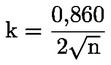
|
|
|
5.3.3.
|
The approval authority or the technical service responsible for verifying the conformity of production shall carry out tests on engines which have been run-in partially or completely, according to the manufacturer's specifications.
|
|
5.3.4.
|
The normal frequency of inspections authorized by the competent authority shall be one per year. If the requirements of section 5.3.2 are not met, the competent authority shall ensure that all necessary steps are taken to re-establish the conformity of production as rapidly as possible.
|
|
6. PARAMETERS DEFINING THE ENGINE FAMILY
The engine family may be defined by basic design parameters which must be common to engines within the family. In some cases there may be interaction of parameters. These effects must also be taken into consideration to ensure that only engines with similar exhaust emission characteristics are included within an engine family.
In order that engines may be considered to belong to the same engine family, the following list of basic parameters must be common:
▼M2
|
6.3.
|
Individual cylinder displacement, within 85 % and 100 % of the largest displacement within the engine family
|
|
6.4.
|
Method of air aspiration
|
|
6.6.
|
Combustion chamber type/design
|
|
6.7.
|
Valve and porting — configurations, size and number
|
|
6.8.
|
Fuel system
For diesel:
For petrol:
|
|
6.9.
|
Miscellaneous features
— Exhaust gas recirculation
— Water injection/emulsion
— Ignition type (compression, spark).
|
|
6.10.
|
Exhaust after-treatment
|
▼B
7. CHOICE OF THE PARENT ENGINE
|
7.1.
|
The parent engine of the family shall be selected using the primary criteria of the highest fuel delivery per stroke at the declared maximum torque speed. In the event that two or more engines share this primary criteria, the parent engine shall be selected using the secondary criteria of highest fuel delivery per stroke at rated speed. Under certain circumstances, the approval authority may conclude that the worst case emission rate of the family can best be characterized by testing a second engine. Thus, the approval authority may select an additional engine for test based upon features which indicate that it may have the highest emission levels of the engines within that family.
|
|
7.2.
|
If engines within the family incorporate other variable features which could be considered to affect exhaust emissions, these features must also be identified and taken into account in the selection of the parent engine.
|
▼M6
8. TYPE APPROVAL REQUIREMENTS FOR STAGES IIIB AND IV
|
8.1.
|
This section shall apply to the type-approval of electronically controlled engines, which uses electronic control to determine both the quantity and timing of injecting fuel (hereafter ‘engine’). This section shall apply irrespective of the technology applied to such engines to comply with the emission limit values set out in sections 4.1.2.5 and 4.1.2.6 of this Annex.
|
|
8.2.
|
Definitions
For the purpose of this section, the following definitions shall apply:
|
8.2.1.
|
‘emission control strategy’ means a combination of an emission control system with one base emission control strategy and with one set of auxiliary emission control strategies, incorporated into the overall design of an engine or non-road mobile machinery into which the engine is installed.
|
|
8.2.2.
|
‘reagent’ means any consumable or non-recoverable medium required and used for the effective operation of the exhaust after-treatment system.
|
|
|
8.3.
|
General requirements
8.3.1.
Requirements for base emission control strategy
|
8.3.1.1.
|
The base emission control strategy, activated throughout the speed and torque operating range of the engine, shall be designed as to enable the engine to comply with the provisions of this Directive
|
|
8.3.1.2.
|
Any base emission control strategy that can distinguish engine operation between a standardised type approval test and other operating conditions and subsequently reduce the level of emission control when not operating under conditions substantially included in the type approval procedure is prohibited.
|
8.3.2.
Requirements for auxiliary emission control strategy
|
8.3.2.1.
|
An auxiliary emission control strategy may be used by an engine or a non-road mobile machine, provided that the auxiliary emission control strategy, when activated, modifies the base emission control strategy in response to a specific set of ambient and/or operating conditions but does not permanently reduce the effectiveness of the emission control system:
(a) where the auxiliary emission control strategy is activated during the type approval test, sections 8.3.2.2 and 8.3.2.3 shall not apply;
(b) where the auxiliary emission control strategy is not activated during the type approval test, it must be demonstrated that the auxiliary emission control strategy is active only for as long as required for the purposes identified in section 8.3.2.3.
|
▼M8
|
8.3.2.2.
|
The control conditions applicable for Stage IIIB and Stage IV are the following:
(a) Control conditions for Stage III B engines:
(i) an altitude not exceeding 1 000 metres (or equivalent atmospheric pressure of 90 kPa);
(ii) an ambient temperature within the range 275 K to 303 K (2 °C to 30 °C);
(iii) the engine coolant temperature above 343 K (70 °C).
Where the auxiliary emission control strategy is activated when the engine is operating within the control conditions set out in points (i), (ii) and (iii), the strategy shall only be activated exceptionally.
(b) Control conditions for Stage IV engines:
(i) the atmospheric pressure greater than or equal to 82,5 kPa;
(ii) the ambient temperature within the following range:
— equal to or above 266 K (– 7 °C),
— less than or equal to the temperature determined by the following equation at the specified atmospheric pressure:  , where: Tc
is the calculated ambient air temperature, K and P
b is the atmospheric pressure, kPa; , where: Tc
is the calculated ambient air temperature, K and P
b is the atmospheric pressure, kPa;
(iii) the engine coolant temperature above 343 K (70 °C).
Where the auxiliary emission control strategy is activated when the engine is operating within the control conditions set out in points (i), (ii) and (iii), the strategy shall only be activated when demonstrated to be necessary for the purposes identified in Section 8.3.2.3. and approved by the Type Approval authority.
(c) Cold temperature operation
By derogation from the requirements of point (b), an auxiliary emission control strategy may be used on a Stage IV engine equipped with exhaust gas recirculation (EGR) when the ambient temperature is below 275 K (2 °C) and if one of the two following criteria is met:
(i) intake manifold temperature is less than or equal to the temperature defined by the following equation:  , where: IMT
c is the calculated intake manifold temperature, K and P
IM is the absolute intake manifold pressure in kPa; , where: IMT
c is the calculated intake manifold temperature, K and P
IM is the absolute intake manifold pressure in kPa;
(ii) engine coolant temperature is less than or equal to the temperature defined by the following equation:  , where: ECT
c is the calculated engine coolant temperature, K and P
IM is the absolute intake manifold pressure, kPa. , where: ECT
c is the calculated engine coolant temperature, K and P
IM is the absolute intake manifold pressure, kPa.
|
▼M6
|
8.3.2.3.
|
An auxiliary emission control strategy may be activated in particular for the following purposes:
(a) by onboard signals, for protecting the engine (including air-handling device protection) and/or non-road mobile machine into which the engine is installed from damage;
▼M8
(b) for operational safety reasons;
▼M6
(c) for prevention of excessive emissions, during cold start or warming-up, during shut-down;
(d) if used to trade-off the control of one regulated pollutant under specific ambient or operating conditions, for maintaining control of all other regulated pollutants, within the emission limit values that are appropriate for the engine concerned. The purpose is to compensate for naturally occurring phenomena in a manner that provides acceptable control of all emission constituents.
|
|
8.3.2.4.
|
The manufacturer shall demonstrate to the technical service at the time of the type-approval test that the operation of any auxiliary emission strategy complies with the provisions of section 8.3.2. The demonstration shall consist of an evaluation of the documentation referred to in section 8.3.3.
|
|
8.3.2.5.
|
Any operation of an auxiliary emission control strategy not compliant with section 8.3.2 is prohibited.
|
8.3.3.
Documentation requirements
|
8.3.3.1.
|
The manufacturer shall provide an information folder accompanying the application for type-approval at the time of submission to the technical service, which ensures access to any element of design and emission control strategy and the means by which the auxiliary strategy directly or indirectly controls the output variables. The information folder shall be made available in two parts:
(a) the documentation package, annexed to the application for type-approval, shall include a full overview of the emission control strategy. Evidence shall be provided that all outputs permitted by a matrix, obtained from the range of control of the individual unit inputs, have been identified. This evidence shall be attached to the information folder as referred to in Annex II;
(b) the additional material, presented to the technical service but not annexed to the application for type-approval, shall include all the modified parameters by any auxiliary emission control strategy and the boundary conditions under which this strategy operates and in particular:
(i) a description of the control logic and of timing strategies and switch points, during all modes of operation for the fuel and other essential systems, resulting in effective emissions control (such as exhaust gas recirculation system (EGR) or reagent dosing);
(ii) a justification for the use of any auxiliary emission control strategy applied to the engine, accompanied by material and test data, demonstrating the effect on exhaust emissions. This justification may be based on test data, sound engineering analysis, or a combination of both;
(iii) a detailed description of algorithms or sensors (where applicable) used for identifying, analysing, or diagnosing incorrect operation of the NOx control system;
(iv) the tolerance used to satisfy the requirements in section 8.4.7.2, regardless of the used means.
|
|
8.3.3.2.
|
The additional material referred to in point (b) of section 8.3.3.1 shall be treated as strictly confidential. It shall be made available to the type-approval authority on request. The type-approval authority shall treat this material as confidential.
|
|
|
8.4.
|
►M8
Requirements on NOx control measures for Stage IIIB engines
◄
|
8.4.1.
|
The manufacturer shall provide information that fully describes the functional operational characteristics of the NOx control measures using the documents set out in section 2 of Appendix 1 to Annex II and in section 2 of Appendix 3 to Annex II.
|
|
8.4.2.
|
If the emission control system requires a reagent, the characteristics of that reagent, including the type of reagent, information on concentration when the reagent is in solution, operational temperature conditions and reference to international standards for composition and quality must be specified by the manufacturer, in section 2.2.1.13 of Appendix 1 and in section 2.2.1.13 of Appendix 3 to Annex II.
|
|
8.4.3.
|
The engine emission control strategy shall be operational under all environmental conditions regularly pertaining in the territory of the Community, especially at low ambient temperatures.
|
|
8.4.4.
|
The manufacturer shall demonstrate that the emission of ammonia during the applicable emission test cycle of the type approval procedure, when a reagent is used, does not exceed a mean value of 25 ppm.
|
|
8.4.5.
|
If separate reagent containers are installed on or connected to a non-road mobile machine, means for taking a sample of the reagent inside the containers must be included. The sampling point must be easily accessible without requiring the use of any specialised tool or device.
|
|
8.4.6.
|
Use and maintenance requirements
|
8.4.6.1.
|
The type approval shall be made conditional, in accordance with Article 4(3), upon providing to each operator of non-road mobile machinery written instructions comprising the following:
(a) detailed warnings, explaining possible malfunctions generated by incorrect operation, use or maintenance of the installed engine, accompanied by respective rectification measures;
(b) detailed warnings on the incorrect use of the machine resulting in possible malfunctions of the engine, accompanied by respective rectification measures;
(c) information on the correct use of the reagent, accompanied by an instruction on refilling the reagent between normal maintenance intervals;
(d) a clear warning, that the type-approval certificate, issued for the type of engine concerned, is valid only when all of the following conditions are met:
(i) the engine is operated, used and maintained in accordance with the instructions provided;
(ii) prompt action has been taken for rectifying incorrect operation, use or maintenance in accordance with the rectification measures indicated by the warnings referred to in point (a) and (b);
(iii) no deliberate misuse of the engine has taken place, in particular deactivating or not maintaining an EGR or reagent dosing system.
The instructions shall be written in a clear and non-technical manner using the same language as is used in the operator’s manual on non-road mobile machinery or engine.
|
|
|
8.4.7.
|
Reagent control (where applicable)
|
8.4.7.1.
|
The type approval shall be made conditional, in accordance with the provisions of section 3 of Article 4, upon providing indicators or other appropriate means, according to the configuration of the non-road mobile machinery, informing the operator on:
(a) the amount of reagent remaining in the reagent storage container and by an additional specific signal, when the remaining reagent is less than 10 % of the full container’s capacity;
(b) when the reagent container becomes empty, or almost empty;
(c) when the reagent in the storage tank does not comply with the characteristics declared and recorded in section 2.2.1.13 of Appendix 1 and section 2.2.1.13 of Appendix 3 to Annex II, according to the installed means of assessment.
(d) when the dosing activity of the reagent is interrupted, in cases other than those executed by the engine ECU or the dosing controller, reacting to engine operating conditions where the dosing is not required, provided that these operating conditions are made available to the type approval authority.
|
|
8.4.7.2.
|
By the choice of the manufacturer the requirements of reagent compliance with the declared characteristics and the associated NOx emission tolerance shall be satisfied by one of the following means:
(a) direct means, such as the use of a reagent quality sensor.
(b) indirect means, such as the use of a NOx sensor in the exhaust to evaluate reagent effectiveness.
(c) any other means, provided that its efficacy is at least equal to the one resulting by the use of the means of points (a) or (b) and the main requirements of this section are maintained.
|
|
|
▼M8
|
8.5.
|
Requirements on NOx control measures for Stage IV engines
|
8.5.1.
|
The manufacturer shall provide information that fully describes the functional operational characteristics of the NOx control measures using the documents set out in Section 2 of Appendix 1 to Annex II and in Section 2 of Appendix 3 to Annex II.
|
|
8.5.2.
|
The engine emission control strategy shall be operational under all environmental conditions regularly pertaining in the territory of the Union, especially at low ambient temperatures. This requirement is not restricted to the conditions under which a base emission control strategy must be used as specified in Section 8.3.2.2.
|
|
8.5.3.
|
When a reagent is used, the manufacturer shall demonstrate that the emission of ammonia over the hot NRTC or NRSC at the type approval procedure does not exceed a mean value of 10 ppm.
|
|
8.5.4.
|
If reagent containers are installed on or connected to a non-road mobile machine, means for taking a sample of the reagent inside the containers must be included. The sampling point must be easily accessible without requiring the use of any specialised tool or device.
|
|
8.5.5.
|
The type approval shall be made conditional, in accordance with Article 4(3), upon the following:
(a) providing to each operator of non-road mobile machinery written maintenance instructions;
(b) providing to the OEM installation documents for the engine, inclusive of the emission control system that is part of the approved engine type;
(c) providing to the OEM instructions for an operator warning system, an inducement system and (where applicable) reagent freeze protection;
(d) the application of provisions on operator instruction, installation documents, operator warning system, inducement system and reagent freeze protection that are set out in Appendix 1 to this Annex.
|
|
|
8.6.
|
Control area for stage IV
In accordance with paragraph 4.1.2.7 of this Annex, for stage IV engines the emissions sampled within the control area defined in Annex I Appendix 2 shall not exceed by more than 100 % the limit values of the emissions in table 4.1.2.6 of this Annex.
8.6.1. Demonstration requirements
The technical service shall select up to three random load and speed points within the control area for testing. The technical service shall also determine a random running order of the test points. The test shall be run in accordance with the principal requirements of the NRSC, but each test point shall be evaluated separately. Each test point shall meet the limit values defined in Section 8.6.
8.6.2. Test requirements
The test shall be carried out immediately after the discrete mode test cycles as described in Annex III.
However, where the manufacturer, pursuant to point 1.2.1 of Annex III, chooses to use the procedure of Annex 4B to UNECE Regulation No 96.03 series of amendments the test shall be carried out as follows:
(a) the test shall be carried out immediately after the discrete mode test cycles as described in points (a) to (e) of paragraph 7.8.1.2 of Annex 4B to UNECE Regulation No 96.03 series of amendments but before the post test procedures (f) or after the Ramped Modal Cycle (RMC) test in points (a) to (d) of paragraph 7.8.2.2 of Annex 4B to UNECE Regulation No 96.03 series of amendments but before the post test procedures (e) as relevant;
(b) the tests shall be carried out as required in points (b) to (e) of paragraph 7.8.1.2 of Annex 4B to UNECE Regulation No 96.03 series of amendments using the multiple filter method (one filter for each test point) for each of the three chosen test points;
(c) a specific emission value shall be calculated (in g/kWh) for each test point;
(d) emissions values may be calculated on a molar basis using Appendix A.7 or on a mass basis using Appendix A.8, but should be consistent with the method used for the discrete mode or RMC test;
(e) for gaseous summation calculations the Nmode shall be set to 1 and a weighting factor of 1 shall be used;
(f) for particulate calculations use the multiple filter method and for summation calculations Nmode shall be set to 1 and a weighting factor of 1 shall be used.
|
|
8.7.
|
Verifying Emissions of Crankcase Gases for stage IV engines
|
8.7.1.
|
No crankcase emissions shall be discharged directly into the ambient atmosphere, with the exception given in paragraph 8.7.3.
|
|
8.7.2.
|
Engines may discharge crankcase emissions into the exhaust upstream of any after treatment device during all operation.
|
|
8.7.3.
|
Engines equipped with turbochargers, pumps, blowers, or superchargers for air induction may discharge crankcase emissions to the ambient atmosphere. In this case the crankcase emissions shall be added to the exhaust emissions (either physically or mathematically) during all emission testing in accordance with paragraph 8.7.3.1 of this section.
8.7.3.1. Crankcase emissions
No crankcase emissions shall be discharged directly into the ambient atmosphere, with the following exception: engines equipped with turbochargers, pumps, blowers, or superchargers for air induction may discharge crankcase emissions to the ambient atmosphere if the emissions are added to the exhaust emissions (either physically or mathematically) during all emission testing. Manufacturers taking advantage of this exception shall install the engines so that all crankcase emission can be routed into the emissions sampling system. For the purpose of this paragraph, crankcase emissions that are routed into the exhaust upstream of exhaust after treatment during all operation are not considered to be discharged directly into the ambient atmosphere.
Open crankcase emissions shall be routed into the exhaust system for emission measurement, as follows:
(a) the tubing materials shall be smooth-walled, electrically conductive, and not reactive with crankcase emissions. Tube lengths shall be minimised as far as possible;
(b) the number of bends in the laboratory crankcase tubing shall be minimised, and the radius of any unavoidable bend shall be maximised;
(c) the laboratory crankcase exhaust tubing shall meet the engine manufacturer’s specifications for crankcase back pressure;
(d) the crankcase exhaust tubing shall connect into the raw exhaust downstream of any after treatment system, downstream of any installed exhaust restriction, and sufficiently upstream of any sample probes to ensure complete mixing with the engine’s exhaust before sampling. The crankcase exhaust tube shall extend into the free stream of exhaust to avoid boundary-layer effects and to promote mixing. The crankcase exhaust tube’s outlet may orient in any direction relative to the raw exhaust flow.
|
|
9. SELECTION OF ENGINE POWER CATEGORY
9.1. For the purposes of establishing the conformity of variable speed engines defined by Section 1.A.(i) and 1.A.(iv) of this Annex with the emission limits given in Section 4 of this Annex they shall be allocated to power bands on the basis of the highest value of the net power measured in accordance with paragraph 2.4 of Annex I.
9.2. For other engine types rated net power shall be used.
Appendix 1
Requirements to ensure the correct operation of NOx control measures
1.
Introduction
This Annex sets out the requirements to ensure the correct operation of NOx control measures. It includes requirements for engines that rely on the use of a reagent in order to reduce emissions.
1.1.
Definitions and abbreviations
‘NOx Control Diagnostic system (NCD)’ means a system on-board the engine which has the capability of:
(a) detecting a NOx Control Malfunction;
(b) identifying the likely cause of NOx control malfunctions by means of information stored in computer memory and/or communicating that information off-board.
‘NOx Control Malfunction (NCM)’ means an attempt to tamper with the NOx control system of an engine or a malfunction affecting that system that might be due to tampering, that is considered by this Directive as requiring the activation of a warning or an inducement system once detected.
‘Diagnostic trouble code (DTC)’ means a numeric or alphanumeric identifier which identifies or labels a NOx Control Malfunction.
‘Confirmed and active DTC’ means a DTC that is stored during the time the NCD system concludes that a malfunction exists.
‘Scan-tool’ means an external test equipment used for off-board communication with the NCD system.
‘NCD engine family’ means a manufacturer’s grouping of engine systems having common methods of monitoring/diagnosing NCMs.
2.
General requirements
The engine system shall be equipped with a NOx Control Diagnostic system (NCD) able to identify the NOx control malfunctions (NCMs) considered by this Annex. Any engine system covered by this section shall be designed, constructed and installed so as to be capable of meeting these requirements throughout the normal life of the engine under normal conditions of use. In achieving this objective it is acceptable that engines which have been used in excess of the useful life period as specified in Section 3.1 of Appendix 5 to Annex III to this Directive show some deterioration in the performance and the sensitivity of the NOx Control Diagnostic system (NCD), such that the thresholds specified in this Annex may be exceeded before the warning and/or inducement systems are activated.
2.1.
Required information
|
2.1.1.
|
If the emission control system requires a reagent, the characteristics of that reagent, including the type of reagent, information on concentration when the reagent is in solution, operational temperature conditions and reference to international standards for composition and quality must be specified by the manufacturer, in Section 2.2.1.13 of Appendix 1 and in Section 2.2.1.13 of Appendix 3 to Annex II.
|
|
2.1.2.
|
Detailed written information fully describing the functional operation characteristics of the operator warning system in paragraph 4 and of the operator inducement system in paragraph 5 shall be provided to the approval authority at the time of type-approval.
|
|
2.1.3.
|
The manufacturer shall provide installation documents that, when used by the OEM, will ensure that the engine, inclusive of the emission control system that is part of the approved engine type, when installed in the machine, will operate, in conjunction with the necessary machinery parts, in a manner that will comply with the requirements of this Annex. This documentation shall include the detailed technical requirements and the provisions of the engine system (software, hardware, and communication) needed for the correct installation of the engine system in the machine.
|
2.2.
Operating conditions
|
2.2.1.
|
The NOx control diagnostic system shall be operational at the following conditions:
(a) ambient temperatures between 266 K and 308 K (– 7 °C and 35 °C);
(b) all altitudes below 1 600 m;
(c) engine coolant temperatures above 343 K (70 °C).
This section shall not apply in the case of monitoring for reagent level in the storage tank where monitoring shall be conducted under all conditions where measurement is technically feasible (for instance, under all conditions when a liquid reagent is not frozen).
|
2.3.
Reagent freeze protection
|
2.3.1.
|
It is permitted to use a heated or a non-heated reagent tank and dosing system. A heated system shall meet the requirements of paragraph 2.3.2. A non-heated system shall meet the requirements of paragraph 2.3.3.
|
2.3.1.1.
|
The use of a non-heated reagent tank and dosing system shall be indicated in the written instructions to the owner of the machine.
|
|
|
2.3.2.
|
Reagent tank and dosing system
|
2.3.2.1.
|
If the reagent has frozen, the reagent shall be available for use within a maximum of 70 minutes after the start of the engine at 266 K (– 7 °C) ambient temperature.
|
|
2.3.2.2.
|
Design criteria for a heated system A heated system shall be so designed that it meets the performance requirements set out in this section when tested using the procedure defined.
2.3.2.2.1. The reagent tank and dosing system shall be soaked at 255 K (– 18 °C) for 72 hours or until the reagent becomes solid, whichever occurs first.
2.3.2.2.2. After the soak period in paragraph 2.3.2.2.1, the machine/engine shall be started and operated at 266 K (– 7 °C) ambient temperature or lower as follows:
(a) 10 to 20 minutes idling,
(b) followed by up to 50 minutes at no more than 40 per cent of rated load.
2.3.2.2.3. At the conclusion of the test procedure in paragraph 2.3.2.2.2, the reagent dosing system shall be fully functional.
|
|
2.3.2.3.
|
Evaluation of the design criteria may be performed in a cold chamber test cell using an entire machine or parts representative of those to be installed on a machine or based on field tests.
|
|
|
2.3.3.
|
Activation of the operator warning and inducement system for a non-heated system
|
2.3.3.1.
|
The operator warning system described in paragraph 4 shall be activated if no reagent dosing occurs at an ambient temperature ≤ 266 K (– 7 °C).
|
|
2.3.3.2.
|
The severe inducement system described in paragraph 5.4 shall be activated if no reagent dosing occurs within a maximum of 70 minutes after engine start at an ambient temperature ≤ 266 K (– 7 °C).
|
|
2.4.
Diagnostic requirements
|
2.4.1.
|
The NOx Control Diagnostic system (NCD) shall be able to identify the NOx control malfunctions (NCMs) considered by this Annex by means of Diagnostic Trouble Codes (DTCs) stored in the computer memory and to communicate that information off-board upon request.
|
|
2.4.2.
|
Requirements for recording Diagnostic Trouble Codes (DTCs)
|
2.4.2.1.
|
The NCD system shall record a DTC for each distinct NOx Control Malfunction (NCM).
|
|
2.4.2.2.
|
The NCD system shall conclude within 60 minutes of engine operation whether a detectable malfunction is present. At this time, a ‘confirmed and active’ DTC shall be stored and the warning system be activated according to paragraph 4.
|
|
2.4.2.3.
|
In cases where more than 60 minutes running time is required for the monitors to accurately detect and confirm a NCM (e.g. monitors using statistical models or with respect to fluid consumption on the machine), the Approval Authority may permit a longer period for monitoring provided the manufacturer justifies the need for the longer period (for example by technical rationale, experimental results, in-house experience, etc.).
|
|
|
2.4.3.
|
Requirements for erasing Diagnostic trouble codes (DTCs):
(a) DTCs shall not be erased by the NCD system itself from the computer memory until the failure related to that DTC has been remedied;
(b) the NCD system may erase all the DTCs upon request of a proprietary scan or maintenance tool that is provided by the engine manufacturer upon request, or using a pass code provided by the engine manufacturer.
|
|
2.4.4.
|
An NCD system shall not be programmed or otherwise designed to partially or totally deactivate based on age of the machine during the actual life of the engine, nor shall the system contain any algorithm or strategy designed to reduce the effectiveness of the NCD system over time.
|
|
2.4.5.
|
Any reprogrammable computer codes or operating parameters of the NCD system shall be resistant to tampering.
|
|
2.4.6.
|
NCD engine family The manufacturer is responsible for determining the composition of an NCD engine family. Grouping engine systems within an NCD engine family shall be based on good engineering judgement and be subject to approval by the Approval Authority.
Engines that do not belong to the same engine family may still belong to the same NCD engine family.
2.4.6.1. Parameters defining an NCD engine family
An NCD engine family is characterised by basic design parameters that shall be common to engine systems within the family.
In order that engine systems are considered to belong to the same NCD engine family, the following list of basic parameters shall be similar:
(a) emission control systems;
(b) methods of NCD monitoring;
(c) criteria for NCD monitoring;
(d) monitoring parameters (e.g. frequency).
These similarities shall be demonstrated by the manufacturer by means of relevant engineering demonstration or other appropriate procedures and subject to the approval of the Approval Authority.
The manufacturer may request approval by the Approval Authority of minor differences in the methods of monitoring/diagnosing the NCD system due to engine system configuration variation, when these methods are considered similar by the manufacturer and they differ only in order to match specific characteristics of the components under consideration (for example size, exhaust flow, etc.); or their similarities are based on good engineering judgement.
|
3.
Maintenance requirements
3.1. The manufacturer shall furnish or cause to be furnished to all owners of new engines or machines written instructions about the emission control system and its correct operation.
These instructions shall state that if the emission control system is not functioning correctly, the operator will be informed of a problem by the operator warning system and that activation of the operator inducement system as a consequence of ignoring this warning will result in the machine being unable to conduct its mission.
3.2. The instructions shall indicate requirements for the proper use and maintenance of engines in order to maintain their emissions performance, including where relevant the proper use of consumable reagents.
3.3. The instructions shall be written in a clear and non-technical manner using the same language as is used in the operator’s manual on the non-road mobile machinery or engine.
3.4. The instructions shall specify whether consumable reagents have to be refilled by the operator between normal maintenance intervals. The instructions shall also specify the required reagent quality. They shall indicate how the operator should refill the reagent tank. The information shall also indicate a likely rate of reagent consumption for the engine type and how often it should be replenished.
3.5. The instructions shall state that use of, and refilling of, a required reagent of the correct specifications is essential in order for the engine to comply with the requirements for the issuing of the type approval for that engine type.
3.6. The instructions shall explain how the operator warning and inducement systems work. In addition, the consequences, in terms of performance and fault logging, of ignoring the warning system and not replenishing the reagent or rectifying the problem shall be explained.
4.
Operator warning system
4.1. The machine shall include an operator warning system using visual alarms that informs the operator when a low reagent level, incorrect reagent quality, interruption of dosing or a malfunction of the type specified in paragraph 9 has been detected that will lead to activation of the operator inducement system if not rectified in a timely manner. The warning system shall remain active when the operator inducement system described in paragraph 5 has been activated.
4.2. The warning shall not be the same as the warning used for the purposes of signalling a malfunction or other engine maintenance, though it may use the same warning system.
4.3. The operator warning system may consist of one or more lamps, or display short messages, which may include, for example, messages indicating clearly:
— the remaining time before activation of the low-level and/or severe inducements,
— the amount of low-level and/or severe inducement, for example the amount of torque reduction,
— the conditions under which machine disablement can be cleared.
Where messages are displayed, the system used for displaying these messages may be the same as the one used for other maintenance purposes.
4.4. At the choice of the manufacturer, the warning system may include an audible component to alert the operator. The cancelling of audible warnings by the operator is permitted.
4.5. The operator warning system shall be activated as specified in paragraphs 2.3.3.1, 6.2, 7.2, 8.4, and 9.3 respectively.
4.6. The operator warning system shall be deactivated when the conditions for its activation have ceased to exist. The operator warning system shall not be automatically deactivated without the reason for its activation having been remedied.
4.7. The warning system may be temporarily interrupted by other warning signals providing important safety related messages.
4.8. Details of the operator warning system activation and deactivation procedures are described in Section 11.
4.9. As part of the application for type-approval under this Directive, the manufacturer shall demonstrate the operation of the operator warning system, as specified in Section 11.
5.
Operator inducement system
|
5.1.
|
The machine shall incorporate an operator inducement system based on one of the following principles:
5.1.1. a two-stage inducement system starting with a low-level inducement (performance restriction) followed by a severe inducement (effective disablement of machine operation);
5.1.2. a one-stage severe inducement system (effective disablement of machine operation) activated under the conditions of a low-level inducement system as specified in paragraphs 6.3.1, 7.3.1, 8.4.1, and 9.4.1.
|
|
5.2.
|
Upon prior approval of the type approval authority, the engine may be fitted with a means to disable the operator inducement during an emergency declared by a national or regional government, their emergency services or their armed services.
|
|
5.3.
|
Low-level inducement system
5.3.1. The low-level inducement system shall be activated after any of the conditions specified in paragraphs 6.3.1, 7.3.1, 8.4.1, and 9.4.1 has occurred.
5.3.2. The low-level inducement system shall gradually reduce the maximum available engine torque across the engine speed range by at least 25 per cent between the peak torque speed and the governor breakpoint as shown in Figure 1. The rate of torque reduction shall be a minimum of 1 % per minute.
5.3.3. Other inducement measures that are demonstrated to the type approval authority as having the same or greater level of severity may be used.
Figure 1
Low-level inducement torque reduction scheme

|
|
5.4.
|
Severe inducement system
5.4.1. The severe inducement system shall be activated after any of the conditions specified in paragraphs 2.3.3.2, 6.3.2, 7.3.2, 8.4.2, and 9.4.2 has occurred.
5.4.2. The severe inducement system shall reduce the machine’s utility to a level that is sufficiently onerous as to cause the operator to remedy any problems related to Sections 6 to 9. The following strategies are acceptable:
5.4.2.1. Engine torque between the peak torque speed and the governor breakpoint shall be gradually reduced from the low-level inducement torque in Figure 1 by a minimum of 1 per cent per minute to 50 per cent of maximum torque or lower and engine speed shall be gradually reduced to 60 per cent of rated speed or lower within the same time period as the torque reduction, as shown in Figure 2.
Figure 2
Severe inducement torque reduction scheme

5.4.2.2. Other inducement measures that are demonstrated to the type approval authority as having the same or greater level of severity may be used.
|
|
5.5.
|
In order to account for safety concerns and to allow for self-healing diagnostics, use of an inducement override function for releasing full engine power is permitted provided it
— is active for no longer than 30 minutes, and
— is limited to three activations during each period that the operator inducement system is active.
|
|
5.6.
|
The operator inducement system shall be deactivated when the conditions for its activation have ceased to exist. The operator inducement system shall not be automatically deactivated without the reason for its activation having been remedied.
|
|
5.7.
|
Details of the operator inducement system activation and deactivation procedures are described in Section 11.
|
|
5.8.
|
As part of the application for type-approval under this Directive, the manufacturer shall demonstrate the operation of the operator inducement system, as specified in Section 11.
|
6.
Reagent availability
6.1.
Reagent level indicator
The machine shall include an indicator that clearly informs the operator of the level of reagent in the reagent storage tank. The minimum acceptable performance level for the reagent indicator is that it shall continuously indicate the reagent level whilst the operator warning system referred to in paragraph 4 is activated. The reagent indicator may be in the form of an analogue or digital display, and may show the level as a proportion of the full tank capacity, the amount of remaining reagent, or the estimated operating hours remaining.
6.2.
Activation of the operator warning system
6.2.1. The operator warning system specified in paragraph 4 shall be activated when the level of reagent goes below 10 % of the capacity of the reagent tank or a higher percentage at the choice of the manufacturer.
6.2.2. The warning provided shall be sufficiently clear, in conjunction with the reagent indicator, for the operator to understand that the reagent level is low. When the warning system includes a message display system, the visual warning shall display a message indicating a low level of reagent (for example ‘urea level low’, ‘AdBlue level low’, or ‘reagent low’).
6.2.3. The operator warning system does not initially need to be continuously activated (for example a message does not need to be continuously displayed), however activation shall escalate in intensity so that it becomes continuous as the level of the reagent approaches empty and the point where the operator inducement system will come into effect is approached (for example frequency at which a lamp flashes). It shall culminate in an operator notification at a level that is at the choice of the manufacturer, but sufficiently more noticeable at the point where the operator inducement system in paragraph 6.3 comes into effect than when it was first activated.
6.2.4. The continuous warning shall not be easily disabled or ignored. When the warning system includes a message display system, an explicit message shall be displayed (for example ‘fill up urea’, ‘fill up AdBlue’, or ‘fill up reagent’). The continuous warning may be temporarily interrupted by other warning signals providing important safety related messages.
6.2.5. It shall not be possible to turn off the operating warning system until the reagent has been replenished to a level not requiring its activation.
6.3.
Activation of the operator inducement system
6.3.1. The low-level inducement system described in paragraph 5.3 shall be activated if the reagent tank level goes below 2,5 % of its nominally full capacity or a higher percentage at the choice of the manufacturer.
6.3.2. The severe inducement system described in paragraph 5.4 shall be activated if the reagent tank is empty (that is, when the dosing system is unable to draw further reagent from the tank) or at any level below 2,5 % of its nominally full capacity at the discretion of the manufacturer.
6.3.3. Except to the extent permitted by paragraph 5.5, it shall not be possible to turn off the low-level or severe inducement system until the reagent has been replenished to a level not requiring their respective activation.
7.
Reagent quality monitoring
|
7.1.
|
The engine or machine shall include a means of determining the presence of an incorrect reagent on board a machine.
7.1.1. The manufacturer shall specify a minimum acceptable reagent concentration CDmin, which results in tailpipe NOx emissions not exceeding a threshold of 0,9 g/kWh.
7.1.1.1. The correct value of CDmin shall be demonstrated during type approval by the procedure defined in Section 12 and recorded in the extended documentation package as specified in Section 8 of Annex I.
7.1.2. Any reagent concentration lower than CDmin shall be detected and be regarded, for the purpose of Section 7.1, as being incorrect reagent.
7.1.3. A specific counter (‘the reagent quality counter’) shall be attributed to the reagent quality. The reagent quality counter shall count the number of engine operating hours with an incorrect reagent.
7.1.3.1. Optionally, the manufacturer may group the reagent quality failure together with one or more of the failures listed in Sections 8 and 9 into a single counter.
7.1.4. Details of the reagent quality counter activation and deactivation criteria and mechanisms are described in Section 11.
|
|
7.2.
|
Activation of the operator warning system
When the monitoring system confirms that the reagent quality is incorrect, the operator warning system described in paragraph 4 shall be activated. When the warning system includes a message display system, it shall display a message indicating the reason of the warning (for example ‘incorrect urea detected’, ‘incorrect AdBlue detected’, or ‘incorrect reagent detected’).
|
|
7.3.
|
Activation of the operator inducement system
7.3.1. The low-level inducement system described in paragraph 5.3 shall be activated if the reagent quality is not rectified within a maximum of 10 engine operating hours after the activation of the operator warning system described in paragraph 7.2.
7.3.2. The severe inducement system described in paragraph 5.4 shall be activated if the reagent quality is not rectified within a maximum of 20 engine operating hours after the activation of the operator warning system in described paragraph 7.2.
7.3.3. The number of hours prior to activation of the inducement systems shall be reduced in case of a repetitive occurrence of the malfunction according to the mechanism described in Section 11.
|
8.
Reagent dosing activity
|
8.1.
|
The engine shall include a means of determining interruption of dosing.
|
|
8.2.
|
Reagent dosing activity counter
8.2.1. A specific counter shall be attributed to the dosing activity (the ‘dosing activity counter’). The counter shall count the number of engine operating hours which occur with an interruption of the reagent dosing activity. This is not required where such interruption is demanded by the engine ECU because the machine operating conditions are such that the machine’s emission performance does not require reagent dosing.
8.2.1.1. Optionally, the manufacturer may group the reagent dosing failure together with one or more of the failures listed in Sections 7 and 9 into a single counter.
8.2.2. Details of the reagent dosing activity counter activation and deactivation criteria and mechanisms are described in Section 11.
|
|
8.3.
|
Activation of the operator warning system
The operator warning system described in paragraph 4 shall be activated in the case of interruption of dosing which sets the dosing activity counter in accordance with paragraph 8.2.1. When the warning system includes a message display system, it shall display a message indicating the reason of the warning (e.g. ‘urea dosing malfunction”, ‘AdBlue dosing malfunction’, or ‘reagent dosing malfunction’).
|
|
8.4.
|
Activation of the operator inducement system
8.4.1. The low-level inducement system described in paragraph 5.3 shall be activated if an interruption in reagent dosing is not rectified within a maximum of 10 engine operating hours after the activation of the operator warning system in paragraph 8.3.
8.4.2. The severe inducement system described in paragraph 5.4 shall be activated if an interruption in reagent dosing is not rectified within a maximum of 20 engine operating hours after the activation of the operator warning system in paragraph 8.3.
8.4.3. The number of hours prior to activation of the inducement systems shall be reduced in case of a repetitive occurrence of the malfunction according to the mechanism described in Section 11.
|
9.
Monitoring failures that may be attributed to tampering
|
9.1.
|
In addition to the level of reagent in the reagent tank, the reagent quality, and the interruption of dosing, the following failures shall be monitored because they may be attributed to tampering:
(ii) failures of the NOx Control Diagnostic (NCD) system, as described in paragraph 9.2.1.
|
|
9.2.
|
Monitoring requirements
|
9.2.1.
|
The NOx Control Diagnostic (NCD) system shall be monitored for electrical failures and for removal or deactivation of any sensor that prevents it from diagnosing any other failures mentioned in paragraphs 6 to 8 (component monitoring).
A non-exhaustive list of sensors that affect the diagnostic capability are those directly measuring NOx concentration, urea quality sensors, ambient sensors and sensors used for monitoring reagent dosing activity, reagent level, or reagent consumption.
|
|
9.2.2.
|
EGR valve counter
9.2.2.1. A specific counter shall be attributed to an impeded EGR valve. The EGR valve counter shall count the number of engine operating hours when the DTC associated to an impeded EGR valve is confirmed to be active.
9.2.2.1.1. Optionally, the manufacturer may group the impeded EGR valve failure together with one or more of the failures listed in Sections 7, 8 and 9.2.3 into a single counter.
9.2.2.2. Details of the EGR valve counter activation and deactivation criteria and mechanisms are described in Section 11.
|
|
9.2.3.
|
NCD system counter(s)
9.2.3.1. A specific counter shall be attributed to each of the monitoring failures considered in paragraph 9.1 (ii). The NCD system counters shall count the number of engine operating hours when the DTC associated to a malfunction of the NCD system is confirmed to be active. Grouping of several faults into a single counter is permitted.
9.2.3.1.1. Optionally, the manufacturer may group the NCD system failure together with one or more of the failures listed in Sections 7, 8 and 9.2.2 into a single counter.
9.2.3.2. Details of the NCD system counter(s) activation and deactivation criteria and mechanisms are described in Section 11.
|
|
|
9.3.
|
Activation of the operator warning system
The operator warning system described in paragraph 4 shall be activated in case any of the failures specified in paragraph 9.1 occur, and shall indicate that an urgent repair is required. When the warning system includes a message display system, it shall display a message indicating the reason of the warning (for example ‘reagent dosing valve disconnected’, or ‘critical emission failure’).
|
|
9.4.
|
Activation of the operator inducement system
|
9.4.1.
|
The low-level inducement system described in paragraph 5.3 shall be activated if a failure specified in paragraph 9.1 is not rectified within a maximum of 36 engine operating hours after the activation of the operator warning system in paragraph 9.3.
|
|
9.4.2.
|
The severe inducement system described in paragraph 5.4 shall be activated if a failure specified in paragraph 9.1 is not rectified within a maximum of 100 engine operating hours after the activation of the operator warning system in paragraph 9.3.
|
|
9.4.3.
|
The number of hours prior to activation of the inducement systems shall be reduced in case of a repetitive occurrence of the malfunction according to the mechanism described in Section 11.
|
|
|
9.5.
|
As an alternative to the requirements in paragraph 9.2, the manufacturer may use a NOx sensor located in the exhaust gas. In this case,
— the NOx value shall not exceed a threshold of 0,9 g/kWh,
— use of a single failure ‘high NOx — root cause unknown’ may be used,
— Section 9.4.1 shall read ‘within 10 engine hours’,
— Section 9.4.2 shall read ‘within 20 engine hours’.
|
10.
Demonstration requirements
10.1.
General
The compliance to the requirements of this Annex shall be demonstrated during type-approval by performing, as illustrated in Table 1 and specified in this section:
(a) a demonstration of the warning system activation;
(b) a demonstration of the low level inducement system activation, if applicable;
(c) a demonstration of the severe inducement system activation.
Table 1
Illustration of the content of the demonstration process according to the provisions in Sections 10.3 and 10.4 of this Appendix
|
Mechanism
|
Demonstration elements
|
|
Warning system activation specified in Section 10.3 of this Appendix
|
— Two activation tests (incl. lack of reagent)
— Supplementary demonstration elements, as appropriate
|
|
Low-level inducement activation specified in Section 10.4 of this Appendix
|
— Two activation tests (incl. lack of reagent)
— Supplementary demonstration elements, as appropriate
— One torque reduction test
|
|
Severe inducement activation specified in Section 10.4.6 of this Appendix
|
— Two activation tests (incl. lack of reagent)
— Supplementary demonstration elements, as appropriate
|
10.2.
Engine families And NCD engine families
The compliance of an engine family or an NCD engine family with the requirements of this Section 10 may be demonstrated by testing one of the members of the considered family, provided the manufacturer demonstrates to the approval authority that the monitoring systems necessary for complying with the requirements of this Annex are similar within the family.
|
10.2.1.
|
The demonstration that the monitoring systems for other members of the NCD family are similar may be performed by presenting to the approval authorities such elements as algorithms, functional analyses, etc.
|
|
10.2.2.
|
The test engine is selected by the manufacturer in agreement with the approval authority. It may or may not be the parent engine of the considered family.
|
|
10.2.3.
|
In the case where engines of an engine family belong to an NCD engine family that has already been type-approved according to paragraph 10.2.1 (Figure 3), the compliance of that engine family is deemed to be demonstrated without further testing, provided the manufacturer demonstrates to the authority that the monitoring systems necessary for complying with the requirements of this Annex are similar within the considered engine and NCD engine families.
Figure 3
Previously demonstrated conformity of an NCD engine family

|
10.3.
Demonstration of the warning system activation
|
10.3.1.
|
The compliance of the warning system activation shall be demonstrated by performing two tests: lack of reagent, and one failure category considered in Section 7 to 9 of this Annex.
|
|
10.3.2.
|
Selection of the failures to be tested
|
10.3.2.1.
|
For the purpose of demonstrating the activation of the warning system in case of a wrong reagent quality, a reagent shall be selected with a dilution of the active ingredient at least as dilute as that communicated by the manufacturer according to the requirements of Section 7 of this Annex
|
|
10.3.2.2.
|
For the purpose of demonstrating the activation of the warning system in case of failures that may be attributed to tampering, and are defined in Section 9 of this Annex the selection shall be performed according to the following requirements:
10.3.2.2.1. The manufacturer shall provide the approval authority with a list of such potential failures.
10.3.2.2.2. The failure to be considered in the test shall be selected by the approval authority from this list referred to in Section 10.3.2.2.1.
|
|
|
10.3.3.
|
Demonstration
|
10.3.3.1.
|
For the purpose of this demonstration, a separate test shall be performed for each of the failures considered in Section 10.3.1.
|
|
10.3.3.2.
|
During a test, no failure shall be present other than the one addressed by the test.
|
|
10.3.3.3.
|
Prior to starting a test, all DTC shall have been erased.
|
|
10.3.3.4.
|
At the request of the manufacturer, and with the agreement of the approval authority, the failures subject to testing may be simulated.
|
|
10.3.3.5.
|
Detection of failures other than lack of reagent For failures other than lack of reagent, once the failure installed or simulated, the detection of that failure shall be performed as follows:
10.3.3.5.1. The NCD system shall respond to the introduction of a failure selected as appropriate by the type approval authority in accordance to the provisions of this Appendix. This is considered to be demonstrated if activation occurs within two consecutive NCD test-cycles according to paragraph 10.3.3.7 of this Appendix.
When it has been specified in the monitoring description and agreed by the Approval Authority that a specific monitor needs more than two NCD test-cycles to complete its monitoring, the number of NCD test-cycles may be increased to three NCD test-cycles.
Each individual NCD test-cycle in the demonstration test may be separated by an engine shut-off. The time until the next start-up shall take into consideration any monitoring that may occur after engine shut-off and any necessary condition that must exist for monitoring to occur at the next start-up.
10.3.3.5.2. The demonstration of the warning system activation is deemed to be accomplished if, at the end of each demonstration test performed according to Section 10.3.2.1, the warning system has been properly activated and the DTC for the selected failure has got the ‘confirmed and active’ status.
|
|
10.3.3.6.
|
Detection in case of lack of reagent For the purpose of demonstrating the activation of the warning system in case of lack of reagent, the engine system shall be operated over one or more NCD test cycles at the discretion of the manufacturer.
10.3.3.6.1. The demonstration shall start with a level of reagent in the tank to be agreed between the manufacturer and the approval authority but representing not less than 10 per cent of the nominal capacity of the tank.
10.3.3.6.2. The warning system is deemed to have performed in the correct manner if the following conditions are met simultaneously:
(a) the warning system has been activated with a reagent availability greater or equal to 10 per cent of the capacity of the reagent tank, and
(b) the ‘continuous’ warning system has been activated with a reagent availability greater or equal to the value declared by the manufacturer according to the provisions of Section 6 of this Annex.
|
|
10.3.3.7.
|
NCD test cycle
10.3.3.7.1. The NCD test cycle considered in this Section 10 for demonstrating the correct performance of the NCD system is the hot NRTC cycle.
10.3.3.7.2. On request of the manufacturer and with approval of the Approval Authority, an alternative NCD test-cycle can be used (e.g. the NRSC) for a specific monitor. The request shall contain elements (technical considerations, simulation, test results, etc.) demonstrating:
(a) the requested test-cycle results in a monitor that will run in real world driving, and
(b) the applicable NCD test-cycle specified in paragraph 10.3.3.7.1 is shown to be less appropriate for the considered monitoring.
|
|
|
10.3.4.
|
The demonstration of the warning system activation is deemed to be accomplished if, at the end of each demonstration test performed according to Section 10.3.3, the warning system has been properly activated.
|
10.4.
Demonstration of the inducement system activation
|
10.4.1.
|
The demonstration of the inducement system activation shall be done by tests performed on an engine test bench.
|
10.4.1.1.
|
Any components or subsystems not physically mounted on the engine system, such as, but not limited to, ambient temperature sensors, level sensors, and operator warning and information systems, that are required in order to perform the demonstrations shall be connected to the engine system for that purpose, or shall be simulated, to the satisfaction of the approval authority.
|
|
10.4.1.2.
|
If the manufacturer chooses, and subject to the agreement of the approval authority, the demonstration tests may be performed on a complete machine or machinery either by mounting the machine on a suitable test bed or by running it on a test track under controlled conditions.
|
|
|
10.4.2.
|
The test sequence shall demonstrate the activation of the inducement system in case of lack of reagent and in case of one of the failures defined in Sections 7, 8, or 9 of this Annex.
|
|
10.4.3.
|
For the purpose of this demonstration:
(a) the approval authority shall select, in addition to the lack of reagent, one of the failures defined in Sections 7, 8 or 9 of this Annex that has been previously used in the demonstration of the warning system activation;
(b) the manufacturer shall, in agreement with the approval authority, be permitted to accelerate the test by simulating the achievement of a certain number of operating hours;
(c) the achievement of the torque reduction required for low-level inducement may be demonstrated at the same time as the general engine performance approval process performed in accordance with this Directive. Separate torque measurement during the inducement system demonstration is not required in this case;
(d) the severe inducement shall be demonstrated according to the requirements of Section 10.4.6 of this Appendix.
|
|
10.4.4.
|
The manufacturer shall, in addition, demonstrate the operation of the inducement system under those failure conditions defined in Sections 7, 8 or 9 of this Annex which have not been chosen for use in demonstration tests described in Sections 10.4.1 to 10.4.3.
These additional demonstrations may be performed by presentation to the approval authority of a technical case using evidence such as algorithms, functional analyses, and the result of previous tests.
|
10.4.4.1.
|
These additional demonstrations shall in particular demonstrate to the satisfaction of the approval authority the inclusion of the correct torque reduction mechanism in the engine ECU.
|
|
|
10.4.5.
|
Demonstration test of the low level inducement system
|
10.4.5.1.
|
This demonstration starts when the warning system or when appropriate ‘continuous’ warning system has been activated as a result of the detection of a failure selected by the approval authority.
|
|
10.4.5.2.
|
When the system is being checked for its reaction to the case of lack of reagent in the tank, the engine system shall be run until the reagent availability has reached a value of 2,5 per cent of the nominal full capacity of the tank or the value declared by the manufacturer in accordance with Section 6.3.1 of this Annex at which the low-level inducement system is intended to operate.
10.4.5.2.1. The manufacturer may, with the agreement of the approval authority, simulate continuous running by extracting reagent from the tank, either whilst the engine is running or is stopped.
|
|
10.4.5.3.
|
When the system is checked for its reaction in the case of a failure other than a lack of reagent in the tank, the engine system shall be run for the relevant number of operating hours indicated in Table 3 of this Appendix or, at the choice of the manufacturer, until the relevant counter has reached the value at which the low-level inducement system is activated.
|
|
10.4.5.4.
|
The demonstration of the low level inducement system shall be deemed to be accomplished if, at the end of each demonstration test performed according to Sections 10.4.5.2 and 10.4.5.3, the manufacturer has demonstrated to the approval authority that the engine ECU has activated the torque reduction mechanism.
|
|
|
10.4.6.
|
Demonstration test of the severe inducement system
|
10.4.6.1.
|
This demonstration shall start from a condition where the low-level inducement system has been previously activated and may be performed as a continuation of the tests undertaken to demonstrate the low-level inducement system.
|
|
10.4.6.2.
|
When the system is checked for its reaction in the case of lack of reagent in the tank, the engine system shall be run until the reagent tank is empty, or has reached the level below 2,5 per cent of the nominal full capacity of the tank at which the manufacturer has declared to activate the severe inducement system.
10.4.6.2.1. The manufacturer may, with the agreement of the approval authority, simulate continuous running by extracting reagent from the tank, either whilst the engine is running or is stopped.
|
|
10.4.6.3.
|
When the system is checked for its reaction in the case of a failure that is not a lack of reagent in the tank, the engine system shall then be run for the relevant number of operating hours indicated in Table 3 of this Appendix or, at the choice of the manufacturer, until the relevant counter has reached the value at which the severe inducement system is activated.
|
|
10.4.6.4.
|
The demonstration of the severe inducement system shall be deemed to be accomplished if, at the end of each demonstration test performed according to paragraphs 10.4.6.2 and 10.4.6.3, the manufacturer has demonstrated to the type-approval authority that the severe inducement mechanism considered in this Annex has been activated.
|
|
|
10.4.7.
|
Alternatively, if the manufacturer chooses, and subject to the agreement of the approval authority, the demonstration of the inducement mechanisms may be performed on a complete machine in accordance with the requirements of Section 5.4, either by mounting the machine on a suitable test bed or by running it on a test track under controlled conditions.
|
10.4.7.1.
|
The machine shall be operated until the counter associated with the selected failure has reached the relevant number of operating hours indicated in Table 3 of this Appendix or, as appropriate, until either the reagent tank is empty or, has reached the level below 2,5 per cent of the nominal full capacity of the tank at which the manufacturer has chosen to activate the severe inducement system.
|
|
11.
Description of the operator warning and inducement activation and deactivation mechanisms
|
11.1.
|
To complement the requirements specified in this Annex concerning the warning and inducement activation and deactivation mechanisms, this Section 11 specifies the technical requirements for an implementation of those activation and deactivation mechanisms.
|
|
11.2.
|
Activation and deactivation mechanisms of the warning system
|
11.2.1.
|
The operator warning system shall be activated when the diagnostic trouble code (DTC) associated with a NCM justifying its activation has the status defined in Table 2 of this Appendix.
Table 2
Activation of the operator warning system
|
Failure type
|
DTC status for activation of the warning system
|
|
Poor reagent quality
|
confirmed and active
|
|
Interruption of dosing
|
confirmed and active
|
|
Impeded EGR valve
|
confirmed and active
|
|
Malfunction of the monitoring system
|
confirmed and active
|
|
NOx threshold, if applicable
|
confirmed and active
|
|
|
11.2.2.
|
The operator warning system shall be deactivated when the diagnostic system concludes that the malfunction relevant to that warning is no longer present or when the information including DTCs relative to the failures justifying its activation is erased by a scan tool.
11.2.2.1. Requirements for erasing ‘NOx control information’
11.2.2.1.1. Erasing/resetting ‘NOx control information’ by a scan-tool
On request of the scan tool, the following data shall be erased or reset to the value specified in this Appendix from the computer memory (see Table 3).
Table 3
Erasing/resetting ‘NOx control information’ by a scan-tool
|
NOx control information
|
Erasable
|
Resetable
|
|
All DTCs
|
X
|
|
|
The value of the counter with the highest number of engine operating hours
|
|
X
|
|
The number of engine operating hours from the NCD counter(s)
|
|
X
|
|
11.2.2.1.2.
|
NOx control information shall not be erased by disconnection of the machine’s battery(s).
|
|
11.2.2.1.3.
|
The erasing of ‘NOx control information’ shall only be possible under ‘engine-off’ conditions.
|
|
11.2.2.1.4.
|
When ‘NOx control information’ including DTCs are erased, any counter reading associated with these failures and which is specified in this Annex shall not be erased, but reset to the value specified in the appropriate section of this Annex.
|
|
|
|
11.3.
|
Activation and deactivation mechanism of the operator inducement system
|
11.3.1.
|
The operator inducement system shall be activated when the warning system is active and the counter relevant to the type of NCM justifying its activation has reached the value specified in Table 4 of this Appendix.
|
|
11.3.2.
|
The operator inducement system shall be deactivated when the system no longer detects a malfunction justifying its activation, or if the information including the DTCs relative to the NCMs justifying its activation has been erased by a scan tool or maintenance tool.
|
|
11.3.3.
|
The operator warning and inducement systems shall be immediately activated or deactivated as appropriate according to the provisions of Section 6 of this Annex after assessment of the reagent quantity in the reagent tank. In that case, the activation or deactivation mechanisms shall not depend upon the status of any associated DTC.
|
|
|
11.4.
|
Counter mechanism
11.4.1. General
|
11.4.1.1.
|
To comply with the requirements of this Annex, the system shall contain at least four counters to record the number of hours during which the engine has been operated while the system has detected any of the following:
(a) an incorrect reagent quality;
(b) an interruption of reagent dosing activity;
(c) an impeded EGR valve;
(d) a failure of the NCD system according to Section 9.1(ii) of this Annex.
|
11.4.1.1.1.
|
Optionally, the manufacturer may use one or more counters for grouping the failures indicated in Section 11.4.1.1.
|
|
|
11.4.1.2.
|
Each of the counters shall count up to the maximum value provided in a 2 byte counter with 1 hour resolution and hold that value unless the conditions allowing the counter to be reset to zero are met.
|
|
11.4.1.3.
|
A manufacturer may use a single or multiple NCD system counters. A single counter may accumulate the number of hours of two or more different malfunctions relevant to that type of counter, none of them having reached the time the single counter indicates.
|
11.4.1.3.1.
|
When the manufacturer decides to use multiple NCD system counters, the system shall be capable of assigning a specific monitoring system counter to each malfunction relevant according to this Annex to that type of counters.
|
|
11.4.2. Principle of counters mechanism
|
11.4.2.1.
|
Each of the counters shall operate as follows:
11.4.2.1.1. If starting from zero, the counter shall begin counting as soon as a malfunction relevant to that counter is detected and the corresponding diagnostic trouble code (DTC) has the status defined in Table 2.
11.4.2.1.2. In case of repeated failures, one of the following provisions shall apply at the choice of the manufacturer.
(i) If a single monitoring event occurs and the malfunction that originally activated the counter is no longer detected or if the failure has been erased by a scan tool or a maintenance tool, the counter shall halt and hold its current value. If the counter stops counting when the severe inducement system is active, the counter shall be kept frozen at the value defined in Table 4 of this Appendix or a value of greater than or equal to the counter value for severe inducement minus 30 minutes.
(ii) The counter shall be kept frozen at the value defined in Table 4 of this Appendix or a value greater than or equal to the counter value for severe inducement minus 30 minutes.
11.4.2.1.3. In the case of a single monitoring system counter, that counter shall continue counting if a NCM relevant to that counter has been detected and its corresponding Diagnostic trouble code (DTC) has the status ‘confirmed and active’. It shall halt and hold one of the values specified in Section 11.4.2.1.2, if no NCM that would justify the counter activation is detected or if all the failures relevant to that counter have been erased by a scan tool or a maintenance tool.
Table 4
Counters and inducement
|
|
DTC status for first activation of the counter
|
Counter value for low-level inducement
|
Counter value for severe inducement
|
Frozen value held by the counter
|
|
Reagent quality counter
|
confirmed and active
|
≤ 10 hours
|
≤ 20 hours
|
≥ 90 % of counter value for severe inducement
|
|
Dosing counter
|
confirmed and active
|
≤ 10 hours
|
≤ 20 hours
|
≥ 90 % of counter value for severe inducement
|
|
EGR valve counter
|
confirmed and active
|
≤ 36 hours
|
≤ 100 hours
|
≥ 95 % of counter value for severe inducement
|
|
Monitoring system counter
|
confirmed and active
|
≤ 36 hours
|
≤ 100 hours
|
≥ 95 % of counter value for severe inducement
|
|
NOx threshold, if applicable
|
confirmed and active
|
≤ 10 hours
|
≤ 20 hours
|
≥ 90 % of counter value for severe inducement
|
11.4.2.1.4. Once frozen, the counter shall be reset to zero when the monitors relevant to that counter have run at least once to completion of their monitoring cycle without having detected a malfunction and no malfunction relevant to that counter has been detected during 40 engine operating hours since the counter was last held (see Figure 4).
11.4.2.1.5. The counter shall continue counting from the point at which it had been held if a malfunction relevant to that counter is detected during a period when the counter is frozen (see Figure 4).
|
|
|
11.5.
|
Illustration of the activation and deactivation and counter mechanisms
|
11.5.1.
|
This paragraph illustrates the activation and deactivation and counter mechanisms for some typical cases. The figures and descriptions given in paragraphs 11.5.2, 11.5.3 and 11.5.4 are provided solely for the purposes of illustration in this Annex and should not be referenced as examples of either the requirements of this Directive or as definitive statements of the processes involved. The counter hours in Figures 6 and 7 refer to the maximum severe inducement values in Table 4. For simplification purposes, for example, the fact that the warning system will also be active when the inducement system is active has not been mentioned in the illustrations given.
Figure 4
Reactivation and resetting to zero of a counter after a period when its value has been frozen

|
|
11.5.2.
|
Figure 5 illustrates the operation of the activation and deactivation mechanisms when monitoring the reagent availability for five cases:
— use case 1: the operator continues operating the machine in spite of the warning until machine operation is disabled;
— refilling case 1 (‘adequate’ refilling): the operator refills the reagent tank so that a level above the 10 % threshold is reached. Warning and inducement are de-activated;
— refilling cases 2 and 3 (‘inadequate’ refilling): the warning system is activated. The level of warning depends on the amount of available reagent;
— refilling case 4 (‘very inadequate’ refilling): the low level inducement is activated immediately.
Figure 5
Reagent availability
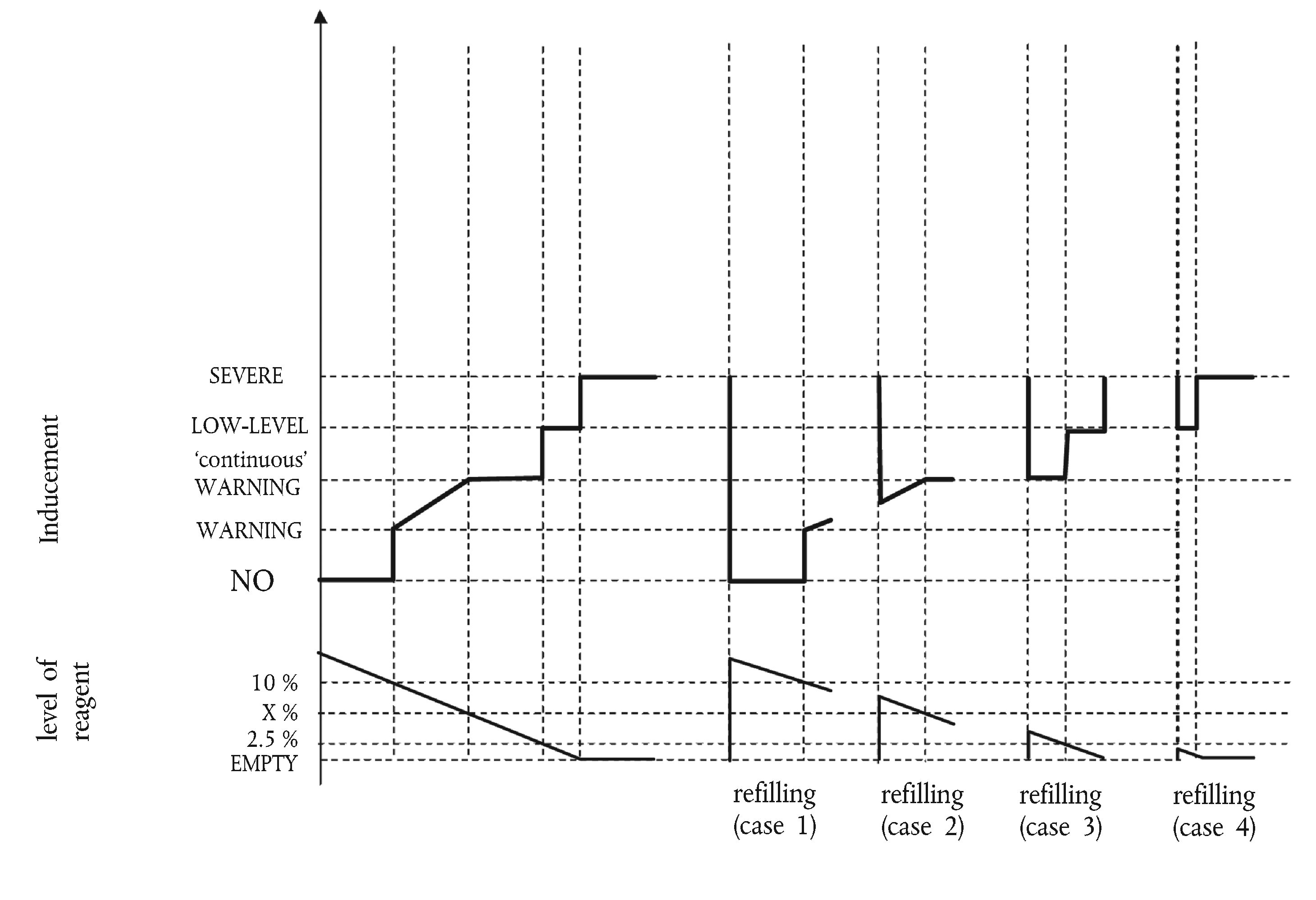
|
|
11.5.3.
|
Figure 6 illustrates three cases of wrong reagent quality:
— use case 1: the operator continues operating the machine in spite of the warning until machine operation is disabled;
— repair case 1 (‘bad’ or ‘dishonest’ repair): after disablement of the machine, the operator changes the quality of the reagent, but soon after, changes it again for a poor quality one. The inducement system is immediately reactivated and machine operation is disabled after 2 engine operating hours;
— repair case 2 (‘good’ repair): after disablement of the machine, the operator rectifies the quality of the reagent. However some time afterwards, he refills again with a poor quality reagent. The warning, inducement and counting processes restart from zero.
Figure 6
Filling with poor reagent quality
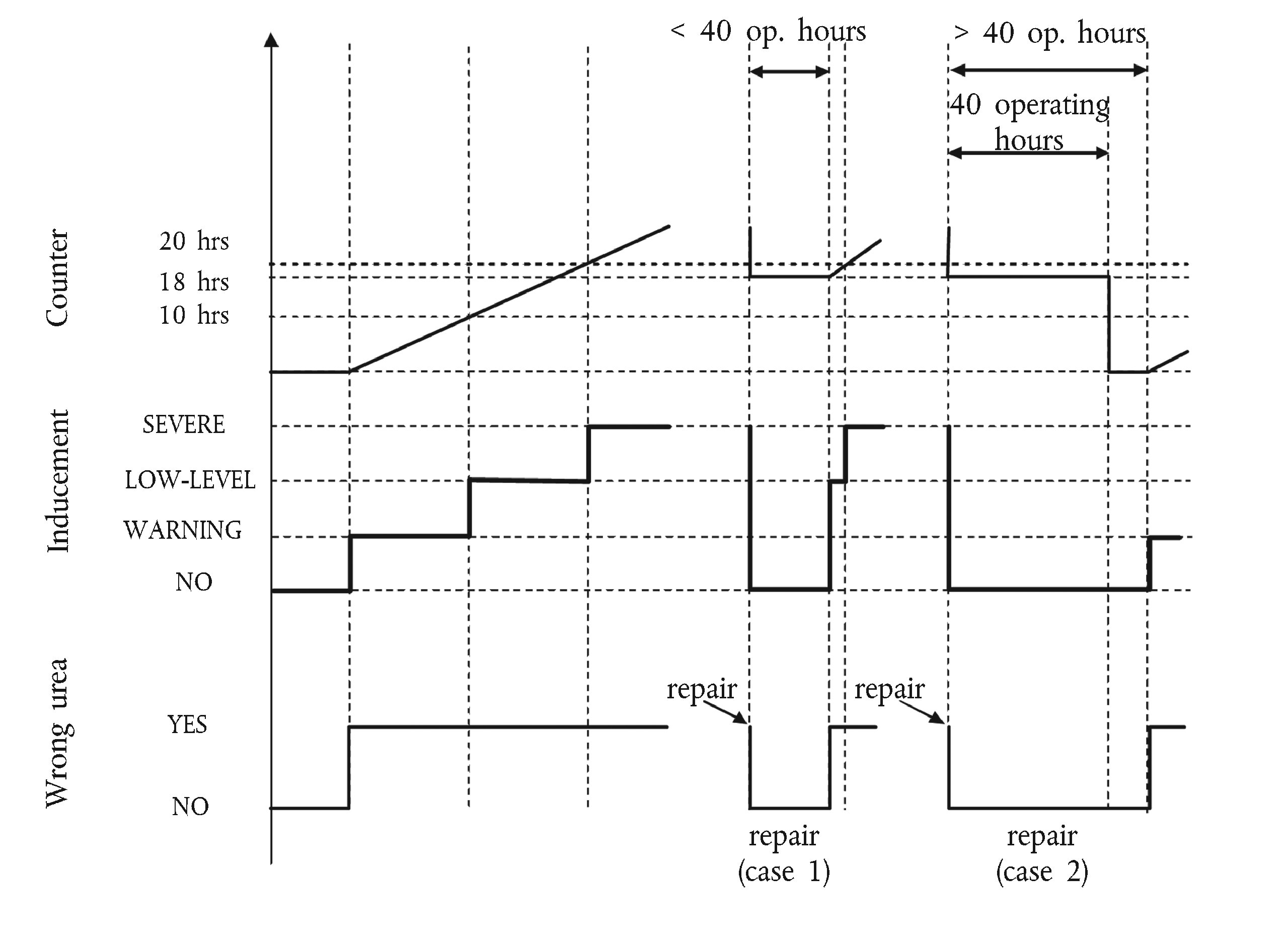
|
|
11.5.4.
|
Figure 7 illustrates three cases of failure of the urea dosing system. This figure also illustrates the process that applies in the case of the monitoring failures described in Section 9 of this Annex:
— use case 1: the operator continues operating the machine in spite of the warning until machine operation is disabled;
— repair case 1 (‘good’ repair): after disablement of the machine, the operator repairs the dosing system. However some time afterwards, the dosing system fails again. The warning, inducement and counting processes restart from zero;
— repair case 2 (‘bad’ repair): during the low-level inducement time (torque reduction), the operator repairs the dosing system. Soon after, however, the dosing system fails again. The low-level inducement system is immediately reactivated and the counter restarts from the value it had at the time of repair.
Figure 7
Failure of the reagent dosing system
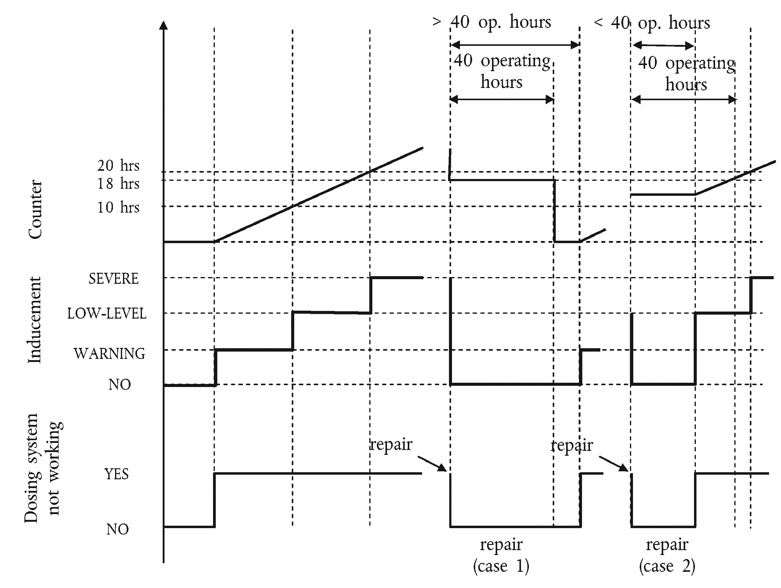
|
|
12.
Demonstration of the minimum acceptable reagent concentration CDmin
12.1. The manufacturer shall demonstrate the correct value of CDmin during type approval by performing the hot part of the NRTC cycle using a reagent with the concentration CDmin.
12.2. The test shall follow the appropriate NCD cycle(s) or manufacturer defined pre-conditioning cycle, permitting a closed loop NOx control system to perform adaptation to the quality of the reagent with the concentration CDmin.
12.3. The pollutant emissions resulting from this test shall be lower than the NOx threshold specified in Section 7.1.1 of this Annex.
Appendix 2
Control Area requirements for stage IV engines
1.
Engine control area
The control area (see Figure 1) is defined as follows:
speed range: speed A to high speed;
where:
speed A = low speed + 15 % (high speed — low speed).
High speed and low speed as defined in Annex III or, if the manufacturer, based on the option indicated in Section 1.2.1 of Annex III, chooses to use the procedure of Annex 4B to UNECE Regulation No 96.03 series of amendments, the definition of paragraphs 2.1.33 and 2.1.37 to UNECE Regulation No 96.03 series of amendments shall be used.
If the measured engine speed A is within ± 3 % of the engine speed declared by the manufacturer, the declared engine speeds shall be used. If the tolerance is exceeded for any of the test speeds, the measured engine speeds shall be used.
|
2.
|
The following engine operating conditions shall be excluded from testing:
(a) points below 30 % of maximum torque;
(b) points below 30 % of maximum power.
The manufacturer may request that the Technical Service excludes operating points from the control area defined in Section 1 and 2 of this Appendix during the certification/type approval. Subject to the positive opinion of the Approval Authority, the Technical Service may accept this exclusion if the manufacturer can demonstrate that the engine is never capable of operating at such points when used in any machine combination.
|
Figure 1
Control area
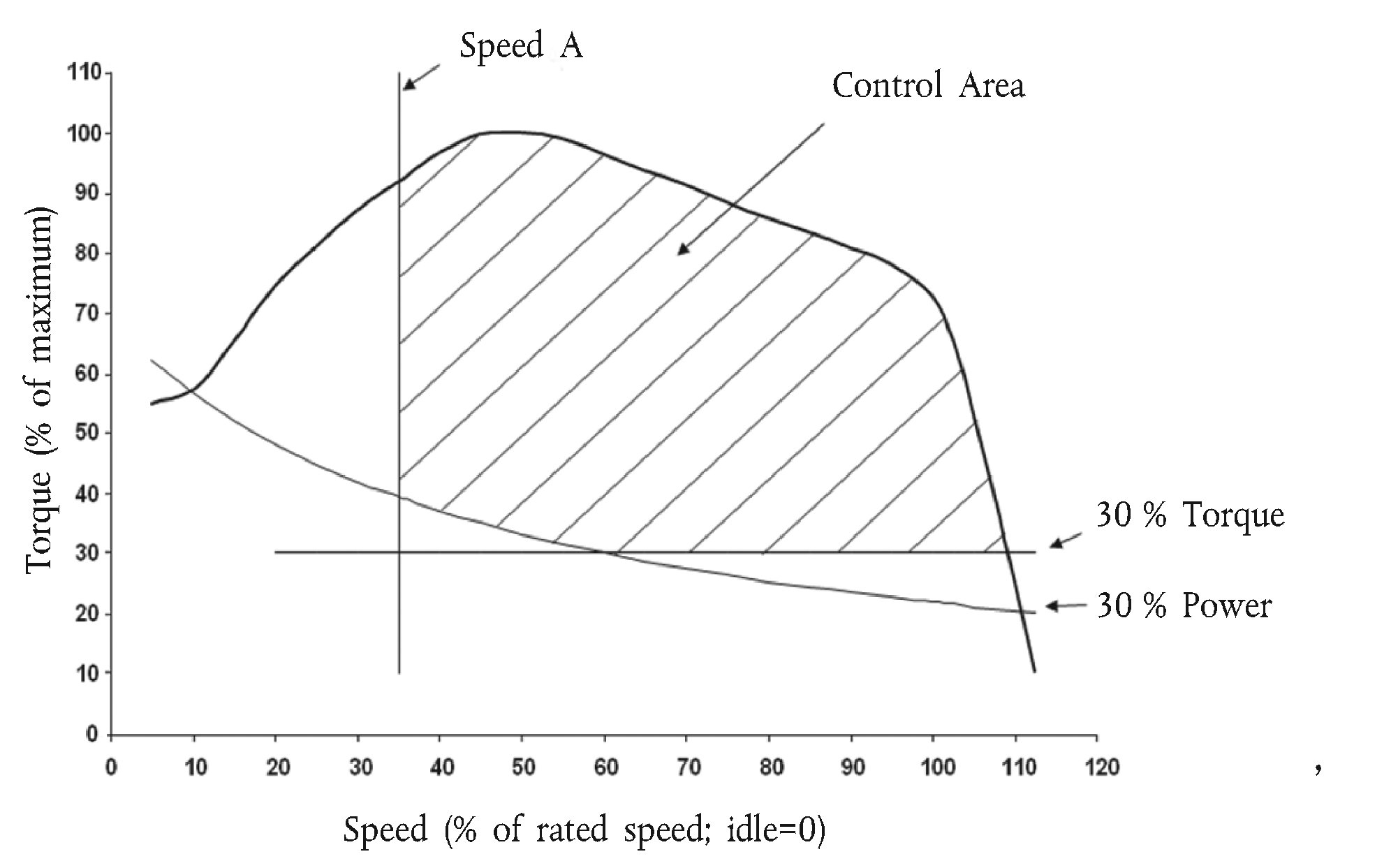
▼B
ANNEX II
INFORMATION DOCUMENT No. …
relating to type-approval and referring to measures against the emission of gaseous and particulate pollutants from internal combustion engines to be installed in non-road mobile machinery
(Directive 97/68/EC as last amended by Directive ../…/EC)

Appendix 1
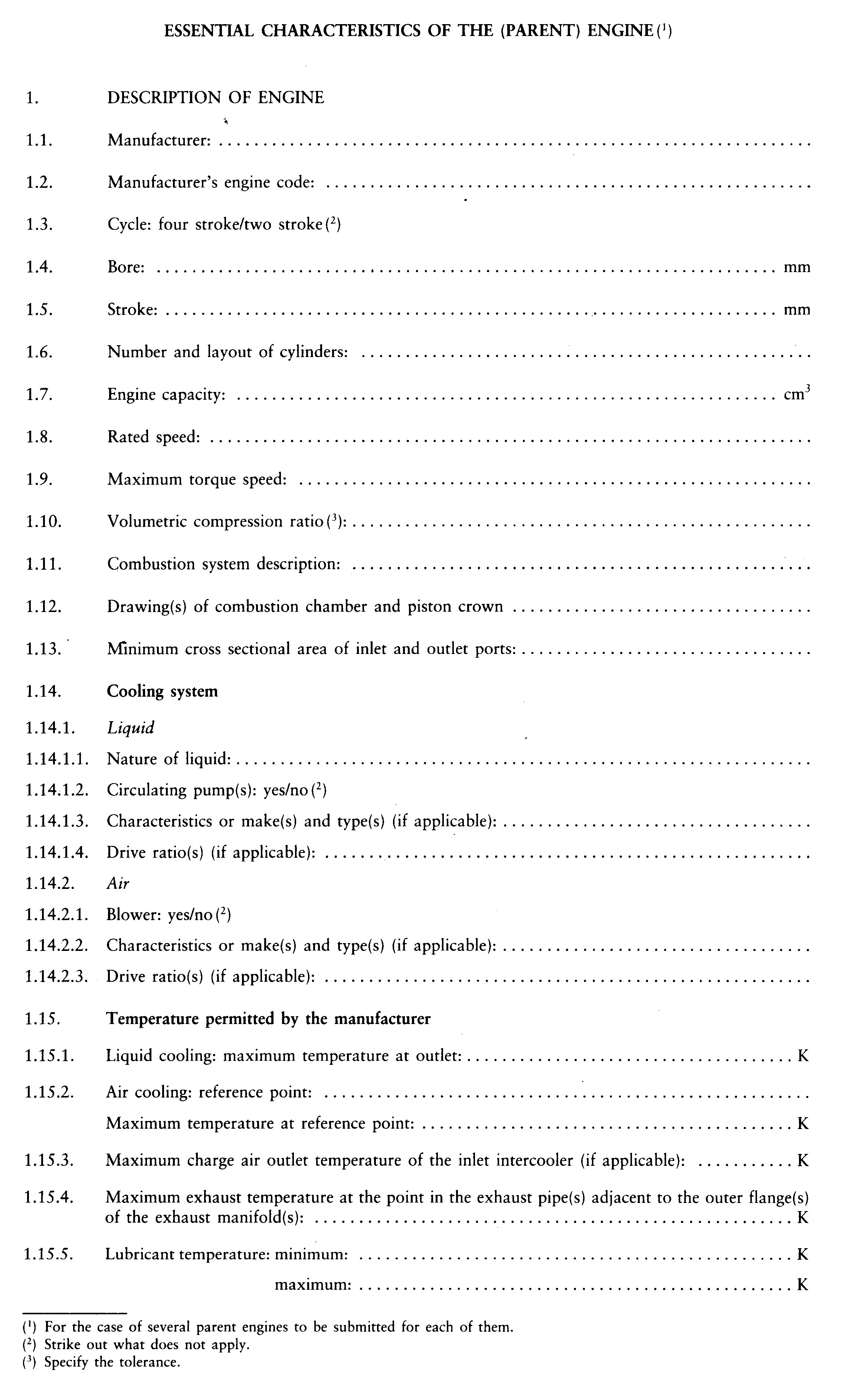
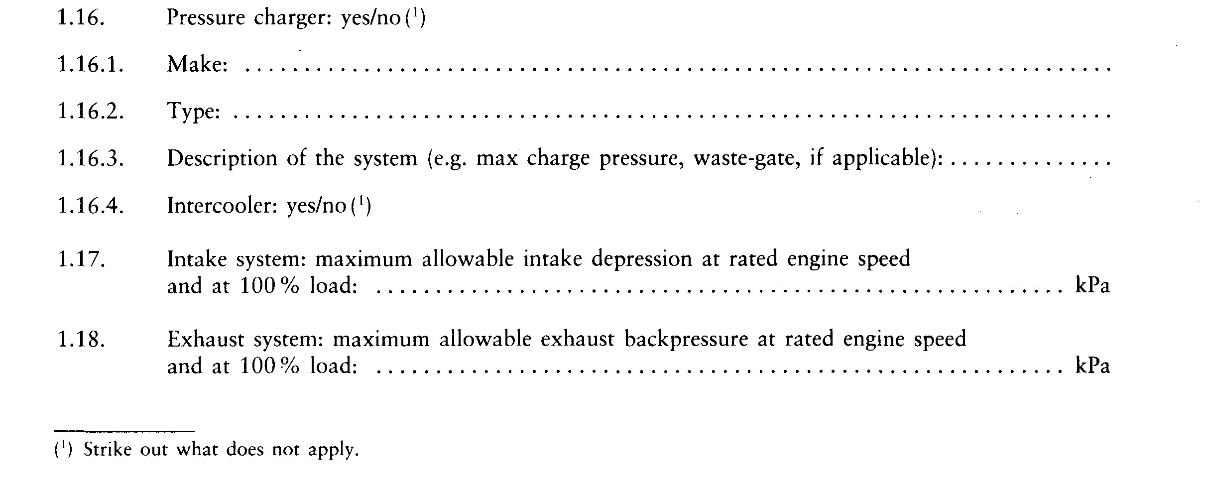
▼M6
2. MEASURES TAKEN AGAINST AIR POLLUTION
|
2.1.
|
Device for recycling crankcase gases: yes/no (
10
) …
|
|
2.2.
|
Additional anti-pollution devices (if any, and if not covered by another heading)
|
2.2.1.
|
Catalytic converter: yes/no (10 11 12)
|
2.2.1.3.
|
Number of catalytic converters and elements …
|
|
2.2.1.4.
|
Dimensions- and volume of the catalytic converter(s): …
|
|
2.2.1.5.
|
Type of catalytic action: …
|
|
2.2.1.6.
|
Total charge of precious metals: …
|
|
2.2.1.7.
|
Relative concentration: …
|
|
2.2.1.8.
|
Substrate (structure and material): …
|
|
2.2.1.10.
|
Type of casing for the catalytic converter(s): …
|
|
2.2.1.11.
|
Location of the catalytic converter(s) (place(s) and maximum/minimum distance(s) from engine): …
|
|
2.2.1.12.
|
Normal operating range (K): …
|
|
2.2.1.13.
|
Consumable reagent (where appropriate): …
|
2.2.1.13.1.
|
Type and concentration of reagent needed for catalytic action: …
|
|
2.2.1.13.2.
|
Normal operational temperature range of reagent: …
|
|
2.2.1.13.3.
|
International standard (where appropriate): …
|
|
|
|
2.2.3.
|
Air injection: yes/no (10 11 12)
|
2.2.3.1.
|
Type (pulse air, air pump, etc.): …
|
|
|
2.2.4.
|
EGR: yes/no (10 11 12)
|
2.2.4.1.
|
Characteristics (cooled/uncooled, high pressure/low pressure, etc.): …
|
|
|
2.2.5.
|
Particulate trap: yes/no (10 11 12)
|
2.2.5.1.
|
Dimensions and capacity of the particulate trap: …
|
|
2.2.5.2.
|
Type and design of the particulate trap: …
|
|
2.2.5.3.
|
Location (place(s) and maximum/minimum distance(s) from engine): …
|
|
2.2.5.4.
|
Method or system of regeneration, description and/or drawing: …
|
|
2.2.5.5.
|
Normal operating temperature (K) and pressure (kPa) range: …
|
|
|
2.2.6.
|
Other systems: yes/no (10 11 12)
|
2.2.6.1.
|
Description and operation: …
|
|
|
▼B
 ►(1) M8
 ►(1) M8
▼M8
5. VALVE TIMING
|
5.1.
|
Maximum lift and angles of opening and closing in relation to dead centres or equivalent data: …
|
|
5.2.
|
Reference and/or setting ranges (
11
) |
|
5.3.
|
Variable valve timing system (if applicable and where intake and/or exhaust)
|
5.3.2.
|
Cam phase shift angle: …
|
|
6. PORTING CONFIGURATION
|
6.1.
|
Position, size and number:
|
7. IGNITION SYSTEM
7.1. Ignition coil
|
7.4.
|
Ignition timing: …
|
7.4.1.
|
Static advance with respect to top dead centre [crank angle degrees] …
|
|
7.4.2.
|
Advance curve, if applicable: …
|
|
▼B
Appendix 2
 ►(3) M8
►(3) M8
►(3) M8
►(3) M8
►(3) M8
Appendix 3

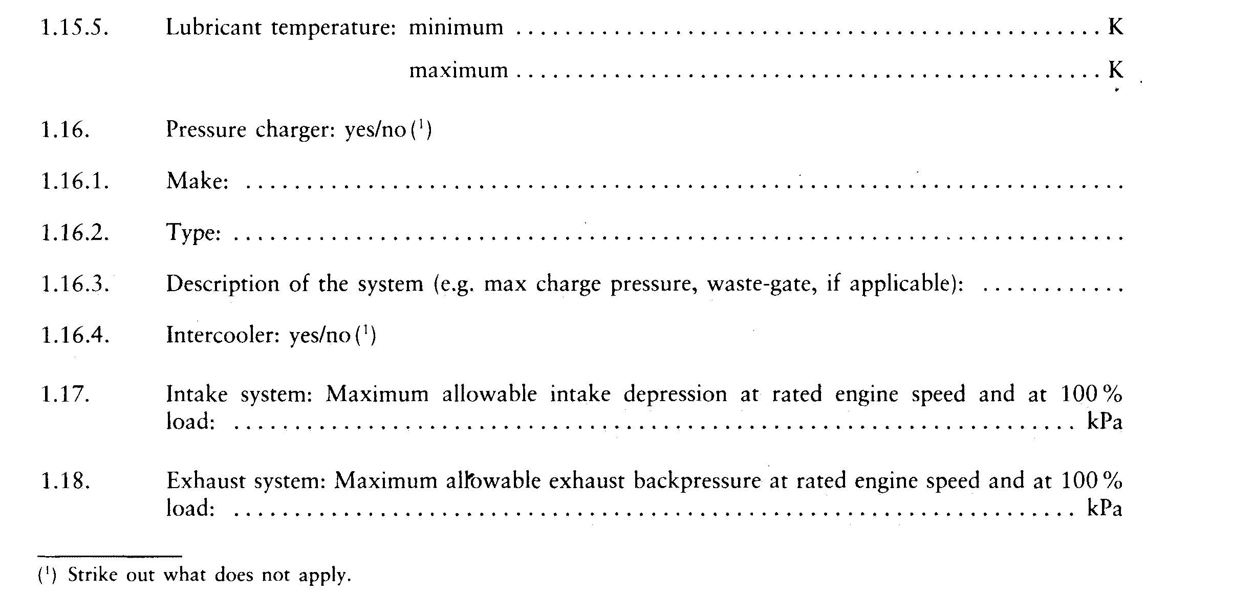
▼M6
2. MEASURES TAKEN AGAINST AIR POLLUTION
|
2.1.
|
Device for recycling crankcase gases: yes/no (
12
) …
|
|
2.2.
|
Additional anti-pollution devices (if any, and if not covered by another heading)
|
2.2.1.
|
Catalytic converter: yes/no (10 11 12)
|
2.2.1.3.
|
Number of catalytic converters and elements …
|
|
2.2.1.4.
|
Dimensions- and volume of the catalytic converter(s): …
|
|
2.2.1.5.
|
Type of catalytic action: …
|
|
2.2.1.6.
|
Total charge of precious metals: …
|
|
2.2.1.7.
|
Relative concentration: …
|
|
2.2.1.8.
|
Substrate (structure and material): …
|
|
2.2.1.10.
|
Type of casing for the catalytic converter(s): …
|
|
2.2.1.11.
|
Location of the catalytic converter(s) (place(s) and maximum/minimum distance(s) from engine): …
|
|
2.2.1.12.
|
Normal operating range (K) …
|
|
2.2.1.13.
|
Consumable reagent (where appropriate): …
|
2.2.1.13.1.
|
Type and concentration of reagent needed for catalytic action: …
|
|
2.2.1.13.2.
|
Normal operational temperature range of reagent: …
|
|
2.2.1.13.3.
|
International standard (where appropriate): …
|
|
|
|
2.2.3.
|
Air injection: yes/no (10 11 12)
|
2.2.3.1.
|
Type (pulse air, air pump, etc.): …
|
|
|
2.2.4.
|
EGR: yes/no (10 11 12)
|
2.2.4.1.
|
Characteristics (cooled/uncooled, high pressure/low pressure, etc.): …
|
|
|
2.2.5.
|
Particulate trap: yes/no (10 11 12)
|
2.2.5.1.
|
Dimensions and capacity of the particulate trap: …
|
|
2.2.5.2.
|
Type and design of the particulate trap: …
|
|
2.2.5.3.
|
Location (place(s) and maximum/minimum distance(s) from engine): …
|
|
2.2.5.4.
|
Method or system of regeneration, description and/or drawing: …
|
|
2.2.5.5.
|
Normal operating temperature (K) and pressure (kPa) range: …
|
|
|
2.2.6.
|
Other systems: yes/no (10 11 12)
|
2.2.6.1.
|
Description and operation: …
|
|
|
▼B
 ►(1) M2
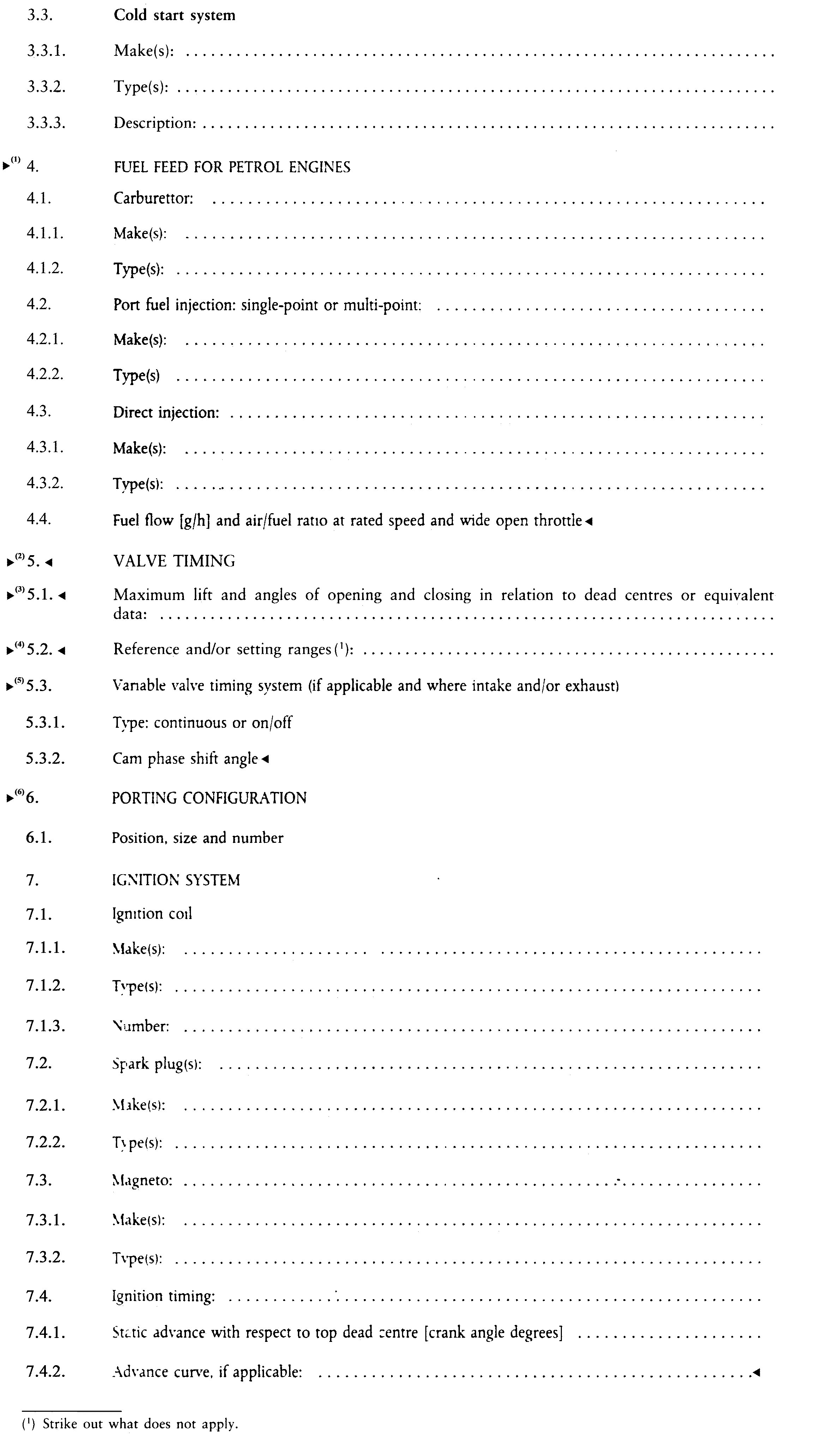 ►(6) M2
►(6) M2
►(6) M2
►(6) M2
►(6) M2
►(6) M2
►(6) M2
►(6) M2
►(6) M2
►(6) M2
►(6) M2
ANNEX III
▼M2
TEST PROCEDURE FOR C.I. ENGINES
▼B
1. INTRODUCTION
▼M6
|
1.1.
|
This Annex describes the method of determining emissions of gaseous and particulate pollutants from the engine to be tested.
The following test cycles shall apply:
— the NRSC (non-road steady cycle) appropriate for the equipment specification which shall be used for the measurement of the emissions of carbon monoxide, hydrocarbons, oxides of nitrogen and particulates for stages I, II, IIIA, IIIB and IV of engines described in points (i) and (ii) of section 1.A of Annex I, and
— the NRTC (non-road transient cycle) which shall be used for the measurement of the emissions of carbon monoxide, hydrocarbons, oxides of nitrogen and particulates for stages IIIB and IV of engines described in point (i) of section 1.A of Annex I,
— for engines intended to be used in inland waterway vessels the ISO test procedure as specified by ISO 8178-4:2002 and IMO (
13
) MARPOL (
14
) 73/78, Annex VI (NOx Code) shall be used,
— for engines intended for propulsion of railcars an NRSC shall be used for the measurement of gaseous and particulate pollutants for stage IIIA and for stage IIIB,
— for engines intended for propulsion of locomotives an NRSC shall be used for the measurement of gaseous and particulate pollutants for stage IIIA and for stage IIIB.
|
▼M8
|
1.2.
|
Selection of test procedure
The test shall be carried out with the engine mounted on a test bench and connected to a dynamometer.
1.2.1. Test procedure for stages I, II, IIIA, IIIB and IV
The test shall be carried out in accordance with the procedure in this Annex or, at the choice of the manufacturer, the test procedure as specified in Annex 4B to UNECE Regulation No 96.03 series of amendments shall be applied.
In addition, the following requirements apply:
(i) durability requirements as set out in Appendix 5 to this Annex;
(ii) engine control area provisions as set out in Section 8.6 of Annex I (stage IV engines only);
(iii) CO2 reporting requirements as set out in Appendix 6 to this Annex for engines tested according to the procedure in this Annex. In case of engines tested according to the procedure in Annex 4B to UNECE Regulation No 96.03 series of amendments, Appendix 7 to this Annex shall apply;
(iv) the reference fuel in Annex V to this Directive shall be used for engines tested according to the requirements in this Annex. The reference fuel in Annex V to this Directive shall be used in case of engines tested according to the requirements in Annex 4B to UNECE Regulation No 96.03 series of amendments.
1.2.1.1. In case that the manufacturer chooses in accordance with Annex I, Section 8.6.2 to use the test procedure specified in Annex 4B to UNECE Regulation No 96.03 series of amendments for testing engines of stages I, II, IIIA or IIIB, the test cycles specified in Section 3.7.1 shall be used.
|
▼M3
|
1.3.
|
Measurement principle: The engine exhaust emissions to be measured include the gaseous components (carbon monoxide, total hydrocarbons and oxides of nitrogen), and the particulates. Additionally, carbon dioxide is often used as a tracer gas for determining the dilution ratio of partial and full flow dilution systems. Good engineering practice recommends the general measurement of carbon dioxide as an excellent tool for the detection of measurement problems during the test run.
1.3.1. NRSC test:
During a prescribed sequence of operating conditions, with the engines warmed up, the amounts of the above exhaust emissions shall be examined continuously by taking a sample from the raw exhaust gas. The test cycle consists of a number of speed and torque (load) modes, which cover the typical operating range of diesel engines. During each mode, the concentration of each gaseous pollutant, exhaust flow and power output shall be determined, and the measured values weighted. The particulate sample shall be diluted with conditioned ambient air. One sample over the complete test procedure shall be taken and collected on suitable filters.
Alternatively, a sample shall be taken on separate filters, one for each mode, and cycle-weighted results computed.
The grams of each pollutant emitted per kilowatt-hour shall be calculated as described in Appendix 3 to this Annex.
▼M6
1.3.2.
NRTC test
The prescribed transient test cycle, based closely on the operating conditions of diesel engines installed in non-road machinery, is run twice:
— the first time (cold start) after the engine has soaked to room temperature and the engine coolant and oil temperatures, after treatment systems and all auxiliary engine control devices are stabilised between 20 and 30 °C,
— the second time (hot start) after a twenty-minute hot soak that commences immediately after the completion of the cold start cycle.
During this test sequence the above pollutants shall be examined. The test sequence consists of a cold start cycle following natural or forced cool-down of the engine, a hot soak period and a hot start cycle, resulting in a composite emissions calculation. Using the engine torque and speed feedback signals of the engine dynamometer, the power shall be integrated with respect to the time of the cycle, resulting in the work produced by the engine over the cycle. The concentrations of the gaseous components shall be determined over the cycle, either in the raw exhaust gas by integration of the analyser signal in accordance with Appendix 3 to this Annex, or in the diluted exhaust gas of a CVS full-flow dilution system by integration or by bag sampling in accordance with Appendix 3 to this Annex. For particulates, a proportional sample shall be collected from the diluted exhaust gas on a specified filter by either partial flow dilution or full-flow dilution. Depending on the method used, the diluted or undiluted exhaust gas flow rate shall be determined over the cycle to calculate the mass emission values of the pollutants. The mass emission values shall be related to the engine work to give the grams of each pollutant emitted per kilowatt-hour.
Emissions (g/kWh) shall be measured during both the cold and hot start cycles. Composite weighted emissions shall be computed by weighting the cold start results 10 % and the hot start results 90 %. Weighted composite results shall meet the limits.
|
▼B
2. TEST CONDITIONS
2.1. General requirements
All volumes and volumetric flow rates shall be related to 273 K (0 oC) and 101,3 kPa.
2.2. Engine test conditions
|
2.2.1.
|
The absolute temperature Ta of the engine intake air expressed in Kelvin, and the dry atmospheric pressure ps, expressed in kPa, shall be measured, and the parameter fa shall be determined according to the following provisions:
Naturally aspirated and mechanically supercharged engines:
Turbocharged engine with or without cooling of the intake air:

|
|
2.2.2.
|
Test validity For a test to be recognized as valid, the parameter fa shall be such that:
▼M1
|
▼M3
|
2.2.3.
|
Engines with charge air cooling The charge air temperature shall be recorded and, at the declared rated speed and full load, shall be within ± 5 K of the maximum charge air temperature specified by the manufacturer. The temperature of the cooling medium shall be at least 293 K (20 °C).
If a test shop system or external blower is used, the charge air temperature shall be set to within ± 5 K of the maximum charge air temperature specified by the manufacturer at the speed of the declared maximum power and full load. Coolant temperature and coolant flow rate of the charge air cooler at the above set point shall not be changed for the whole test cycle. The charge air cooler volume shall be based upon good engineering practice and typical vehicle/machinery applications.
Optionally, the setting of the charge air cooler may be done in accordance with SAE J 1937 as published in January 1995.
|
▼B
2.3. Engine air inlet system
▼M3
The test engine shall be equipped with an air inlet system presenting an air inlet restriction within ± 300 Pa of the value specified by the manufacturer for a clean air cleaner at the engine operating conditions as specified by the manufacturer, which result in maximum air flow. The restrictions are to be set at rated speed and full load. A test shop system may be used, provided it duplicates actual engine operating conditions.
▼B
2.4. Engine exhaust system
▼M3
The test engine shall be equipped with an exhaust system with exhaust back pressure within ± 650 Pa of the value specified by the manufacturer at the engine operating conditions resulting in maximum declared power.
If the engine is equipped with an exhaust after-treatment device, the exhaust pipe shall have the same diameter as found in-use for at least four pipe diameters upstream to the inlet of the beginning of the expansion section containing the after-treatment device. The distance from the exhaust manifold flange or turbocharger outlet to the exhaust after-treatment device shall be the same as in the machine configuration or within the distance specifications of the manufacturer. The exhaust backpressure or restriction shall follow the same criteria as above, and may be set with a valve. The after-treatment container may be removed during dummy tests and during engine mapping, and replaced with an equivalent container having an inactive catalyst support.
▼B
2.5. Cooling system
An engine cooling system with sufficient capacity to maintain the engine at normal operating temperatures prescribed by the manufacturer.
2.6. Lubricating oil
Specifications of the lubricating oil used for the test shall be recorded and presented with the results of the test.
2.7. Test fuel
The fuel shall be the reference fuel specified in
►M2
Annex V ◄ .
The cetane number and the sulphur content of the reference fuel used for test shall be recorded at sections 1.1.1 and 1.1.2 respectively of
►M2
Annex VII ◄ , Appendix 1.
The fuel temperature at the injection pump inlet shall be 306-316 K (33-43 oC).
▼M3
3. TEST RUN (NRSC TEST)
▼M3
3.1. Determination of dynamometer settings
The basis of specific emissions measurement is uncorrected brake power according to ISO 14396: 2002.
Certain auxiliaries, which are necessary only for the operation of the machine and may be mounted on the engine, should be removed for the test. The following incomplete list is given as an example:
— air compressor for brakes
— power steering compressor
— air conditioning compressor
— pumps for hydraulic actuators.
Where auxiliaries have not been removed, the power absorbed by them at the test speeds shall be determined in order to calculate the dynamometer settings, except for engines where such auxiliaries form an integral part of the engine (e.g. cooling fans for air cool engines).
The settings of inlet restriction and exhaust pipe backpressure shall be adjusted to the manufacturer's upper limits, in accordance with sections 2.3. and 2.4.
The maximum torque values at the specified test speeds shall be determined by experimentation in order to calculate the torque values for the specified test modes. For engines which are not designed to operate over a range on a full load torque curve, the maximum torque at the test speeds shall be declared by the manufacturer.
The engine setting for each test mode shall be calculated using the formula:

If the ratio,

the value of PAE may be verified by the technical authority granting type approval.
▼B
►M3
►C1
3.2. ◄
◄ Preparation of the sampling filters
At least one hour before the test, each filter (pair) shall be placed in a closed, but unsealed, petri dish and placed in a weighing chamber for stabilization. At the end of the stabilization period, each filter (pair) shall be weighed and the tare weight shall be recorded. The filter (pair) shall then be stored in a closed petri dish or filter holder until needed for testing. If the filter (pair) is not used within eight hours of its removal from the weighing chamber, it must be reweighed before use.
►M3
►C1
3.3. ◄
◄ Installation of the measuring equipment
The instrumentation and sample probes shall be installed as required. When using a full flow dilution system for exhaust gas dilution, the tailpipe shall be connected to the system.
►M3
►C1
3.4. ◄
◄ Starting the dilution system and engine
The dilution system and the engine shall be started and warmed up until all temperatures and pressures have stabilized at full load and rated speed (section 3.6.2).
▼M3
3.5. Adjustment of the dilution ratio
The particulate sampling system shall be started and running on bypass for the single filter method (optional for the multiple filter method). The particulate background level of the dilution air may be determined by passing dilution air through the particulate filters. If filtered dilution air is used, one measurement may be done at any time prior to, during, or after the test. If the dilution air is not filtered, the measurement must be done on one sample taken for the duration of the test.
The dilution air shall be set to obtain a filter face temperature between 315 K (42 °C) and 325 K (52 °C) at each mode. The total dilution ratio shall not be less than four.
NOTE: For steady-state procedure, the filter temperature may be kept at or below the maximum temperature of 325 K (52 °C) instead of respecting the temperature range of 42 °C to 52 °C.
For the single and multiple filter methods, the sample mass flow rate through the filter shall be maintained at a constant proportion of the dilute exhaust mass flow rate for full flow systems for all modes. This mass ratio shall be within ± 5 % with respect to the averaged value of the mode, except for the first 10 seconds of each mode for systems without bypass capability. For partial flow dilution systems with single filter method, the mass flow rate through the filter shall be constant within ± 5 % with respect to the averaged value of the mode, except for the first 10 seconds of each mode for systems without bypass capability.
For CO2 or NOx concentration controlled systems, the CO2 or NOx content of the dilution air must be measured at the beginning and at the end of each test. The pre and post test background CO2 or NOx concentration measurements of the dilution air must be within 100 ppm or 5 ppm of each other, respectively.
When using a dilute exhaust gas analysis system, the relevant background concentrations shall be determined by sampling dilution air into a sampling bag over the complete test sequence.
Continuous (non-bag) background concentration may be taken at the minimum of three points, at the beginning, at the end, and a point near the middle of the cycle and averaged. At the manufacturer's request background measurements may be omitted.
▼B
►M3
►C1
3.6. ◄
◄ Checking the analysers
The emission analysers shall be set at zero and spanned.
►M3
►C1
3.7. ◄
◄ Test cycle
▼M6
|
3.7.1.
|
Equipment specification according to section 1.A of Annex I:
3.7.1.1.
Specification A
For engines covered by points (i) and (iv) of section 1.A of Annex I, the following 8-mode cycle (
15
) shall be followed in dynamometer operation on the test engine:
|
Mode No
|
Engine speed
(r/min)
|
Load
(%)
|
Weighting factor
|
|
1
|
Rated or reference (1)
|
100
|
0,15
|
|
2
|
Rated or reference (1)
|
75
|
0,15
|
|
3
|
Rated or reference (1)
|
50
|
0,15
|
|
4
|
Rated or reference (1)
|
10
|
0,10
|
|
5
|
Intermediate
|
100
|
0,10
|
|
6
|
Intermediate
|
75
|
0,10
|
|
7
|
Intermediate
|
50
|
0,10
|
|
8
|
Idle
|
—
|
0,15
|
|
(1) Reference speed is defined in section 4.3.1 of Annex III.
|
3.7.1.2.
Specification B
For engines covered by point (ii) of section 1.A of Annex I, the following 5-mode cycle (
16
) shall be followed in dynamometer operation on the test engine:
|
Mode No
|
Engine speed
(r/min)
|
Load
(%)
|
Weighting factor
|
|
1
|
Rated
|
100
|
0,05
|
|
2
|
Rated
|
75
|
0,25
|
|
3
|
Rated
|
50
|
0,30
|
|
4
|
Rated
|
25
|
0,30
|
|
5
|
Rated
|
10
|
0,10
|
The load figures are percentage values of the torque corresponding to the prime power rating defined as the maximum power available during a variable power sequence, which may be run for an unlimited number of hours per year, between stated maintenance intervals and under the stated ambient conditions, the maintenance being carried out as prescribed by the manufacturer.
3.7.1.3.
Specification C
For propulsion engines (
17
) intended to be used in inland waterway vessels the ISO test procedure as specified by ISO 8178-4:2002 and IMO MARPOL 73/78, Annex VI (NOx Code) shall be used.
Propulsion engines that operate on a fixed-pitch propeller curve shall be tested on a dynamometer using the following 4-mode steady-state cycle (
18
) developed to represent in-use operation of commercial marine diesel engines.
|
Mode No
|
Engine speed
(r/min)
|
Load
(%)
|
Weighting factor
|
|
1
|
100 % (Rated)
|
100
|
0,20
|
|
2
|
91 %
|
75
|
0,50
|
|
3
|
80 %
|
50
|
0,15
|
|
4
|
63 %
|
25
|
0,15
|
Fixed speed inland waterway propulsion engines with variable pitch or electrically coupled propellers shall be tested on a dynamometer using the following 4-mode steady-state cycle (
19
) characterised by the same load and weighting factors as the above cycle, but with engine operated in each mode at rated speed:
|
Mode No
|
Engine speed
(r/min)
|
Load
(%)
|
Weighting factor
|
|
1
|
Rated
|
100
|
0,20
|
|
2
|
Rated
|
75
|
0,50
|
|
3
|
Rated
|
50
|
0,15
|
|
4
|
Rated
|
25
|
0,15
|
3.7.1.4.
Specification D
For engines covered by point (v) of section 1.A of Annex I, the following 3-mode cycle (
20
) shall be followed in dynamometer operation on the test engine:
|
Mode No
|
Engine speed
(r/min)
|
Load
(%)
|
Weighting factor
|
|
1
|
Rated
|
100
|
0,25
|
|
2
|
Intermediate
|
50
|
0,15
|
|
3
|
Idle
|
—
|
0,60
|
|
▼B
|
►M3
►C1
3.7.2. ◄
◄
|
Conditioning of the engine Warming up of the engine and the system shall be at maximum speed and torque in order to stabilize the engine parameters according to the recommendations of the manufacturer.
Note: The conditioning period should also prevent the influence of deposits from a former test in the exhaust system. There is also a required period of stabilization between test points which has been included to minimise point to point influences.
|
▼M2
|
►M3
►C1
3.7.3. ◄
◄
|
Test sequence
▼M3
The test sequence shall be started. The test shall be performed in the order of the mode numbers as set out above for the test cycles.
During each mode of the given test cycle after the initial transition period, the specified speed shall be held to within ± 1 % of rated speed or ± 3 min-1, whichever is greater, except for low idle which shall be within the tolerances declared by the manufacturer. The specified torque shall be held so that the average over the period during which the measurements are being taken is within ± 2 % of the maximum torque at the test speed.
For each measuring point a minimum time of 10 minutes is necessary. If for the testing of an engine, longer sampling times are required for reasons of obtaining sufficient particulate mass on the measuring filter the test mode period can be extended as necessary.
The mode length shall be recorded and reported.
The gaseous exhaust emission concentration values shall be measured and recorded during the last three minutes of the mode.
The particulate sampling and the gaseous emission measurement should not commence before engine stabilisation, as defined by the manufacturer, has been achieved and their completion must be coincident.
The fuel temperature shall be measured at the inlet to the fuel injection pump or as specified by the manufacturer, and the location of measurement recorded.
|
▼B
|
►M3
►C1
3.7.4. ◄
◄
|
Analyser response The output of the analysers shall be recorded on a strip chart recorder or measured with an equivalent data acquisition system with the exhaust gas flowing through the analysers at least during the last three minutes of each mode. If bag sampling is applied for the diluted CO and CO2 measurement (see Appendix 1, section 1.4.4), a sample shall be bagged during the last three minutes of each mode, and the bag sample analysed and recorded.
|
|
►M3
►C1
3.7.5. ◄
◄
|
Particulate sampling The particulate sampling can be done either with the single filter method or with the multiple filter method (Appendix 1, section 1.5). Since the results of the methods may differ slightly, the method used must be declared with the results.
For the single filter method the modal weighting factors specified in the test cycle procedure shall be taken into account during sampling by adjusting sample flow rate and/or sampling time, accordingly.
Sampling must be conducted as late as possible within each mode. The sampling time per mode must be at least 20 seconds for the single filter method and at least 60 seconds for the multi-filter method. For systems without bypass capability, the sampling time per mode must be a least 60 seconds for single and multiple filter methods.
|
|
►M3
►C1
3.7.6. ◄
◄
|
Engine conditions The engine speed and load, intake air temperatur, fuel flow and air or exhaust gas flow shall be measured for each mode once the engine has been stabilized.
If the measurement of the exhaust gas flow or the measurement of combustion air and fuel consumption is not possible, it can be calculated using the carbon and oxygen balance method (see Appendix 1, section 1.2.3).
Any additional data required for calculation shall be recorded (see Appendix 3, sections 1.1 and 1.2).
|
►M3
►C1
3.8. ◄
◄ Re-checking the analysers
After the emission test a zero gas and the same span gas will be used for re-checking. The test will be considered acceptable if the difference between the two measuring results is less than 2 %.
▼M3
4. TEST RUN (NRTC TEST)
4.1. Introduction
The non-road transient cycle (NRTC) is listed in Annex III, Appendix 4 as a second-by-second sequence of normalised speed and torque values applicable to all diesel engines covered by this Directive. In order to perform the test on an engine test cell, the normalised values shall be converted to the actual values for the individual engine under test, based on the engine mapping curve. This conversion is referred to as denormalisation, and the test cycle developed is referred to as the reference cycle of the engine to be tested. With these reference speed and torque values, the cycle shall be run on the test cell, and the feedback speed and torque values recorded. In order to validate the test run, a regression analysis between reference and feedback speed and torque values shall be conducted upon completion of the test.
4.1.1. The use of defeat devices or irrational control or irrational emission control strategies shall be prohibited
4.2. Engine mapping procedure
When generating the NRTC on the test cell, the engine shall be mapped before running the test cycle to determine the speed vs torque curve.
4.2.1. Determination of the mapping speed range
The minimum and maximum mapping speeds are defined as follows:
|
Minimum mapping speed
|
=
|
idle speed
|
|
Maximum mapping speed
|
=
|
nhi x 1,02 or speed where full load torque drops off to zero, whichever is lower (where nhi is the high speed, defined as the highest engine speed where 70 % of the rated power is delivered).
|
4.2.2. Engine mapping curve
The engine shall be warmed up at maximum power in order to stabilise the engine parameters according to the recommendation of the manufacturer and good engineering practice. When the engine is stabilised, the engine mapping shall be performed according to the following procedures.
4.2.2.1. Transient map
(a) The engine shall be unloaded and operated at idle speed.
(b) The engine shall be operated at full load setting of the injection pump at minimum mapping speed.
(c) The engine speed shall be increased at an average rate of 8 ± 1 min-1/s from minimum to maximum mapping speed. Engine speed and torque points shall be recorded at a sample rate of at least one point per second.
4.2.2.2. Step map
(a) The engine shall be unloaded and operated at idle speed.
(b) The engine shall be operated at full load setting of the injection pump at minimum mapping speed.
(c) While maintaining full load, the minimum mapping speed shall be maintained for at least 15 s, and the average torque during the last 5 s shall be recorded. The maximum torque curve from minimum to maximum mapping speed shall be determined in no greater than 100 ± 20/min speed increments. Each test point shall be held for at least 15 s, and the average torque during the last 5 s shall be recorded.
4.2.3. Mapping curve generation
All data points recorded under section 4.2.2 shall be connected using linear interpolation between points. The resulting torque curve is the mapping curve and shall be used to convert the normalised torque values of the engine dynamometer schedule of Annex IV into actual torque values for the test cycle, as described in section 4.3.3.
4.2.4. Alternate mapping
If a manufacturer believes that the above mapping techniques are unsafe or unrepresentative for any given engine, alternate mapping techniques may be used. These alternate techniques must satisfy the intent of the specified mapping procedures to determine the maximum available torque at all engine speeds achieved during the test cycles. Deviations from the mapping techniques specified in this section for reasons of safety or representativeness shall be approved by the parties involved along with the justification for their use. In no case, however, shall the torque curve be run by descending engine speeds for governed or turbocharged engines.
4.2.5. Replicate tests
An engine need not be mapped before each and every test cycle. An engine must be remapped prior to a test cycle if:
— an unreasonable amount of time has transpired since the last map, as determined by engineering judgement, or,
— physical changes or recalibrations have been made to the engine, which may potentially affect engine performance.
4.3. Generation of the reference test cycle
▼M6
4.3.1.
Reference speed
The reference speed (nref) corresponds to the 100 % normalised speed values specified in the engine dynamometer schedule of Appendix 4 of Annex III. The actual engine cycle resulting from denormalisation to the reference speed depends largely on selection of the proper reference speed. The reference speed shall be determined by the following formula:
nref = low speed + 0,95 x (high speed – low speed)
(the high speed is the highest engine speed where 70 % of the rated power is delivered, while the low speed is the lowest engine speed where 50 % of the rated power is delivered).
If the measured reference speed is within +/– 3 % of the reference speed as declared by the manufacturer, the declared reference speed may be used for the emissions test. If the tolerance is exceeded, the measured reference speed shall be used for the emissions test (
21
).
▼C1
4.3.2. Denormalisation of engine speed
The speed shall be denormalised using the following equation:

4.3.3. Denormalisation of engine torque
The torque values in the engine dynamometer schedule of Annex III, Appendix 4 are normalised to the maximum torque at the respective speed. The torque values of the reference cycle shall be denormalised, using the mapping curve determined according to Section 4.2.2, as follows:
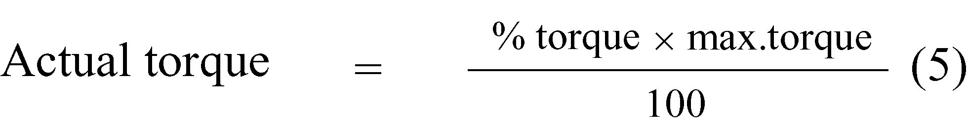
for the respective actual speed as determined in Section 4.3.2.
4.3.4. Example of denormalisation procedure
As an example, the following test point shall be denormalised:
% speed = 43 %
% torque = 82 %
Given the following values:
reference speed = 2 200 /min
idle speed = 600/min
results in

With the maximum torque of 700 Nm observed from the mapping curve at 1 288 /min

4.4. Dynamometer
4.4.1. When using a load cell, the torque signal shall be transferred to the engine axis and the inertia of the dyno shall be considered. The actual engine torque is the torque read on the load cell plus the moment of inertia of the brake multiplied by the angular acceleration. The control system has to perform this calculation in real time.
▼M6
4.5.
Emissions test run
The following flow chart outlines the test sequence:

One or more practice cycles may be run as necessary to check engine, test cell and emissions systems before the measurement cycle.
4.5.1.
Preparation of the sampling filters
At least one hour before the test, each filter shall be placed in a petri dish, which is protected against dust contamination and allows air exchange, and placed in a weighing chamber for stabilisation. At the end of the stabilisation period, each filter shall be weighed and the weight shall be recorded. The filter shall then be stored in a closed petri dish or sealed filter holder until needed for testing. The filter shall be used within eight hours of its removal from the weighing chamber. The tare weight shall be recorded.
4.5.2.
Installation of the measuring equipment
The instrumentation and sample probes shall be installed as required. The tailpipe shall be connected to the full-flow dilution system, if used.
4.5.3.
Starting the dilution system
The dilution system shall be started. The total diluted exhaust gas flow of a full-flow dilution system or the diluted exhaust gas flow through a partial flow dilution system shall be set to eliminate water condensation in the system, and to obtain a filter face temperature between 315 K (42 °C) and 325 K (52 °C).
4.5.4.
Starting the particulate sampling system
The particulate sampling system shall be started and run on by-pass. The particulate background level of the dilution air may be determined by sampling the dilution air prior to entrance of the exhaust into the dilution tunnel. It is preferred that background particulate sample be collected during the transient cycle if another PM sampling system is available. Otherwise, the PM sampling system used to collect transient cycle PM can be used. If filtered dilution air is used, one measurement may be done prior to or after the test. If the dilution air is not filtered, measurements should be carried out prior to the beginning and after the end of the cycle and the values averaged.
4.5.5.
Checking the analysers
The emission analysers shall be set at zero and spanned. If sample bags are used, they shall be evacuated.
4.5.6.
Cool-down requirements
A natural or forced cool-down procedure may be applied. For forced cool-down, good engineering judgement shall be used to set up systems to send cooling air across the engine, to send cool oil through the engine lubrication system, to remove heat from the coolant through the engine cooling system, and to remove heat from an exhaust after-treatment system. In the case of a forced after-treatment cool down, cooling air shall not be applied until the after-treatment system has cooled below its catalytic activation temperature. Any cooling procedure that results in unrepresentative emissions is not permitted.
The cold start cycle exhaust emission test may begin after a cool-down only when the engine oil, coolant and after-treatment temperatures are stabilised between 20 °C and 30 °C for a minimum of 15 minutes.
4.5.7.
Cycle run
4.5.7.1.
Cold start cycle
The test sequence shall commence with the cold start cycle at the completion of the cool-down when all the requirements specified in section 4.5.6 are met.
The engine shall be started according to the starting procedure recommended by the manufacturer in the owner's manual, using either a production starter motor or the dynamometer.
As soon as it is determined that the engine is started, start a ‘free idle’ timer. Allow the engine to idle freely with no-load for 23 ± 1 s. Begin the transient engine cycle such that the first non-idle record of the cycle occurs at 23 ± 1 s. The free idle time is included in the 23 ± 1 s.
The test shall be performed according to the reference cycle as set out in Annex III, Appendix 4. Engine speed and torque command set points shall be issued at 5 Hz (10 Hz recommended) or greater. The set points shall be calculated by linear interpolation between the 1 Hz set points of the reference cycle. Feedback engine speed and torque shall be recorded at least once every second during the test cycle, and the signals may be electronically filtered.
4.5.7.2.
Analyser response
At the start of the engine the measuring equipment shall be started, simultaneously:
— start collecting or analysing dilution air, if a full flow dilution system is used,
— start collecting or analysing raw or diluted exhaust gas, depending on the method used,
— start measuring the amount of diluted exhaust gas and the required temperatures and pressures,
— start recording the exhaust gas mass flow rate, if raw exhaust gas analysis is used,
— start recording the feedback data of speed and torque of the dynamometer.
If raw exhaust measurement is used, the emission concentrations (HC, CO and NOx) and the exhaust gas mass flow rate shall be measured continuously and stored with at least 2 Hz on a computer system. All other data may be recorded with a sample rate of at least 1 Hz. For analogue analysers the response shall be recorded, and the calibration data may be applied online or offline during the data evaluation.
If a full flow dilution system is used, HC and NOx shall be measured continuously in the dilution tunnel with a frequency of at least 2 Hz. The average concentrations shall be determined by integrating the analyser signals over the test cycle. The system response time shall be no greater than 20 s, and shall be coordinated with CVS flow fluctuations and sampling time/test cycle offsets, if necessary. CO and CO2 shall be determined by integration or by analysing the concentrations in the sample bag collected over the cycle. The concentrations of the gaseous pollutants in the dilution air shall be determined by integration or by collection in the background bag. All other parameters that need to be measured shall be recorded with a minimum of one measurement per second (1 Hz).
4.5.7.3.
Particulate sampling
At the start of the engine the particulate sampling system shall be switched from by-pass to collecting particulates.
If a partial flow dilution system is used, the sample pump(s) shall be adjusted so that the flow rate through the particulate sample probe or transfer tube is maintained proportional to the exhaust mass flow rate.
If a full flow dilution system is used, the sample pump(s) shall be adjusted so that the flow rate through the particulate sample probe or transfer tube is maintained at a value within ± 5 % of the set flow rate. If flow compensation (i.e. proportional control of sample flow) is used, it must be demonstrated that the ratio of main tunnel flow to particulate sample flow does not change by more than ± 5 % of its set value (except for the first 10 seconds of sampling).
NOTE: For double dilution operation, sample flow is the net difference between the flow rate through the sample filters and the secondary dilution airflow rate.
The average temperature and pressure at the gas meter(s) or flow instrumentation inlet shall be recorded. If the set flow rate cannot be maintained over the complete cycle (within ± 5 %) because of high particulate loading on the filter, the test shall be voided. The test shall be rerun using a lower flow rate and/or a larger diameter filter.
4.5.7.4.
Engine stalling during the cold start test cycle
If the engine stalls anywhere during the cold start test cycle, the engine shall be preconditioned, then the cool-down procedure repeated; finally the engine shall be restarted, and the test repeated. If a malfunction occurs in any of the required test equipment during the test cycle, the test shall be voided.
4.5.7.5.
Operations after cold start cycle
At the completion of the cold start cycle of the test, the measurement of the exhaust gas mass flow rate, the diluted exhaust gas volume, the gas flow into the collecting bags and the particulate sample pump shall be stopped. For an integrating analyser system, sampling shall continue until system response times have elapsed.
The concentrations of the collecting bags, if used, shall be analysed as soon as possible and in any case not later than 20 minutes after the end of the test cycle.
After the emission test, a zero gas and the same span gas shall be used for re-checking the analysers. The test will be considered acceptable if the difference between the pre-test and post-test results is less than 2 % of the span gas value.
The particulate filters shall be returned to the weighing chamber no later than one hour after completion of the test. They shall be conditioned in a petri dish, which is protected against dust contamination and allows air exchange, for at least one hour, and then weighed. The gross weight of the filters shall be recorded.
4.5.7.6.
Hot soak
Immediately after the engine is turned off, the engine cooling fan(s) shall be turned off if used, as well as the CVS blower (or disconnect the exhaust system from the CVS), if used.
Allow the engine to soak for 20 ± 1 minutes. Prepare the engine and dynamometer for the hot start test. Connect evacuated sample collection bags to the dilute exhaust and dilution air sample collection systems. Start the CVS (if used or not already on) or connect the exhaust system to the CVS (if disconnected). Start the sample pumps (except the particulate sample pump(s), the engine cooling fan(s) and the data collection system.
The heat exchanger of the constant volume sampler (if used) and the heated components of any continuous sampling system(s) (if applicable) shall be preheated to their designated operating temperatures before the test begins.
Adjust the sample flow rates to the desired flow rate and set the CVS gas flow measuring devices to zero. Carefully install a clean particulate filter in each of the filter holders and install assembled filter holders in the sample flow line.
4.5.7.7.
Hot start cycle
As soon as it is determined that the engine is started, start a ‘free idle’ timer. Allow the engine to idle freely with no-load for 23 ± 1 s. Begin the transient engine cycle such that the first non-idle record of the cycle occurs at 23 ± 1 s. The free idle time is included in the 23 ± 1 s.
The test shall be performed according to the reference cycle as set out in Appendix 4 to Annex III. Engine speed and torque command set points shall be issued at 5 Hz (10 Hz recommended) or greater. The set points shall be calculated by linear interpolation between the 1 Hz set points of the reference cycle. Feedback engine speed and torque shall be recorded at least once every second during the test cycle, and the signals may be electronically filtered.
The procedure described in previous sections 4.5.7.2 and 4.5.7.3 shall then be repeated.
4.5.7.8.
Engine stalling during the hot start cycle
If the engine stalls anywhere during the hot start cycle, the engine may be shut off and re-soaked for 20 minutes. The hot start cycle may then be rerun. Only one hot re-soak and hot start cycle restart is permitted.
4.5.7.9.
Operations after hot start cycle
At the completion of the hot start cycle, the measurement of the exhaust gas mass flow rate, the diluted exhaust gas volume, the gas flow into the collecting bags and the particulate sample pump shall be stopped. For an integrating analyser system, sampling shall continue until system response times have elapsed.
The concentrations of the collecting bags, if used, shall be analysed as soon as possible and in any case not later than 20 minutes after the end of the test cycle.
After the emission test, a zero gas and the same span gas shall be used for re-checking the analysers. The test will be considered acceptable if the difference between the pre-test and post-test results is less than 2 % of the span gas value.
The particulate filters shall be returned to the weighing chamber no later than one hour after completion of the test. They shall be conditioned in a petri dish, which is protected against dust contamination and allows air exchange, for at least one hour, and then weighed. The gross weight of the filters shall be recorded.
▼C1
4.6. Verification of the test run
4.6.1. Data shift
To minimise the biasing effect of the time lag between the feedback and reference cycle values, the entire engine speed and torque feedback signal sequence may be advanced or delayed in time with respect to the reference speed and torque sequence. If the feedback signals are shifted, both speed and torque must be shifted by the same amount in the same direction.
4.6.2. Calculation of the cycle work
The actual cycle work Wact (kWh) shall be calculated using each pair of engine feedback speed and torque values recorded. The actual cycle work Wact is used for comparison to the reference cycle work Wref and for calculating the brake specific emissions. The same methodology shall be used for integrating both reference and actual engine power. If values are to be determined between adjacent reference or adjacent measured values, linear interpolation shall be used.
In integrating the reference and actual cycle work, all negative torque values shall be set equal to zero and included. If integration is performed at a frequency of less than 5 Hertz, and if, during a given time segment, the torque value changes from positive to negative or negative to positive, the negative portion shall be computed and set equal to zero. The positive portion shall be included in the integrated value.
Wact shall be between – 15 % and + 5 % of Wref.
4.6.3. Validation statistics of the test cycle
Linear regressions of the feedback values on the reference values shall be performed for speed, torque and power. This shall be done after any feedback data shift has occurred, if this option is selected. The method of least squares shall be used, with the best fit equation having the form:
y = mx + b
where:
|
y
|
=
|
feedback (actual) value of speed (min-1), torque (N·m), or power (kW)
|
|
m
|
=
|
slope of the regression line
|
|
x
|
=
|
reference value of speed (min-1), torque (N·m), or power (kW)
|
|
b
|
=
|
y intercept of the regression line
|
The standard error of estimate (SE) of y on x and the coefficient of determination (r2) shall be calculated for each regression line.
It is recommended that this analysis be performed at 1 Hertz. For a test to be considered valid, the criteria of Table 1 must be met.
Table 1 — Regression line tolerances
|
|
Speed
|
Torque
|
Power
|
|
Standard error of estimate (SE) of Y on X
|
max 100 min-1
|
max 13 % of power map maximum engine torque
|
max 8 % of power map maximum engine power
|
|
Slope of the regression line, m
|
0,95 to 1,03
|
0,83 — 1,03
|
0,89 — 1,03
|
|
Coefficient of determination, r2
|
min 0,9700
|
min 0,8800
|
min 0,9100
|
|
Y intercept of the regression line, b
|
± 50 min-1
|
± 20 N·m or ± 2 % of max torque, whichever is greater
|
± 4 kW or ± 2 % of max power, whichever is greater
|
For regression purposes only, point deletions are permitted where noted in Table 2 before doing the regression calculation. However, those points must not be deleted for the calculation of cycle work and emissions. An idle point is defined as a point having a normalised reference torque of 0 % and a normalised reference speed of 0 %. Point deletion may be applied to the whole or to any part of the cycle.
Table 2 — Permitted point deletions from regression analysis (points to which the point deletion is applied have to be specified)
|
Condition
|
Speed and/or torque and/or power points which may be deleted with reference to the conditions listed in the left column
|
|
First 24 (±1) s and last 25 s
|
Speed, torque and power
|
|
Wide open throttle, and torque feedback < 95 % torque reference
|
Torque and/or power
|
|
Wide open throttle, and speed feedback < 95 % speed reference
|
Speed and/or power
|
|
Closed throttle, speed feedback > idle speed + 50 min-1, and torque feedback > 105 % torque reference
|
Torque and/or power
|
|
Closed throttle, speed feedback ≤ idle speed + 50 min-1, and torque feedback = Manufacturer defined/measured idle torque ± 2 % of max torque
|
Speed and/or power
|
|
Closed throttle and speed feedback > 105 % speed reference
|
Speed and/or power
|
▼M3
Appendix 1
MEASUREMENT AND SAMPLING PROCEDURES
1. MEASUREMENT AND SAMPLING PROCEDURES (NRSC TEST)
Gaseous and particulate components emitted by the engine submitted for testing shall be measured by the methods described in Annex VI. The methods of Annex VI describe the recommended analytical systems for the gaseous emissions (Section 1.1) and the recommended particulate dilution and sampling systems (Section 1.2).
1.1. Dynamometer specification
An engine dynamometer with adequate characteristics to perform the test cycle described in Annex III, Section 3.7.1 shall be used. The instrumentation for torque and speed measurement shall allow the measurement of the power within the given limits. Additional calculations may be necessary. The accuracy of the measuring equipment must be such that the maximum tolerances of the figures given in point 1.3 are not exceeded.
1.2. Exhaust gas flow
The exhaust gas flow shall be determined by one of the methods mentioned in sections 1.2.1 to 1.2.4.
1.2.1. Direct measurement method
Direct measurement of the exhaust flow by flow nozzle or equivalent metering system (for detail see ISO 5167:2000).
Note: Direct gaseous flow measurement is a difficult task. Precautions must be taken to avoid measurement errors that will impact emission value errors.
1.2.2. Air and fuel measurement method
Measurement of the airflow and the fuel flow.
Air flow-meters and fuel flow-meters with the accuracy defined in Section 1.3 shall be used.
The calculation of the exhaust gas flow is as follows:
GEXHW = GAIRW + GFUEL (for wet exhaust mass)
1.2.3. Carbon balance method
Exhaust mass calculation from fuel consumption and exhaust gas concentrations using the carbon balance method (Annex III, Appendix 3).
1.2.4. Tracer measurement method
This method involves measurement of the concentration of a tracer gas in the exhaust. A known amount of an inert gas (e.g. pure helium) shall be injected into the exhaust gas flow as a tracer. The gas is mixed and diluted by the exhaust gas, but must not react in the exhaust pipe. The concentration of the gas shall then be measured in the exhaust gas sample.
In order to ensure complete mixing of the tracer gas, the exhaust gas sampling probe shall be located at least 1 m or 30 times the diameter of the exhaust pipe, whichever is larger, downstream of the tracer gas injection point. The sampling probe may be located closer to the injection point if complete mixing is verified by comparing the tracer gas concentration with the reference concentration when the tracer gas is injected upstream of the engine.
The tracer gas flow rate shall be set so that the tracer gas concentration at engine idle speed after mixing becomes lower than the full scale of the trace gas analyser.
The calculation of the exhaust gas flow is as follows:

where
|
GEXHW
|
=
|
instantaneous exhaust mass flow (kg/s)
|
|
GT
|
=
|
tracer gas flow (cm3/min)
|
|
concmix
|
=
|
instantaneous concentration of the tracer gas after mixing, (ppm)
|
|
ρEXH
|
=
|
density of the exhaust gas (kg/m3)
|
|
conca
|
=
|
background concentration of the tracer gas in the intake air (ppm)
|
The background concentration of the tracer gas (conc
a) may be determined by averaging the background concentration measured immediately before and after the test run.
When the background concentration is less than 1 % of the concentration of the tracer gas after mixing (conc
mix.) at maximum exhaust flow, the background concentration may be neglected.
The total system shall meet the accuracy specifications for the exhaust gas flow and shall be calibrated according to Appendix 2, Section 1.11.2.
1.2.5. Air flow and air to fuel ratio measurement method
This method involves exhaust mass calculation from the air flow and the air to fuel ratio. The calculation of the instantaneous exhaust gas mass flow is as follows:

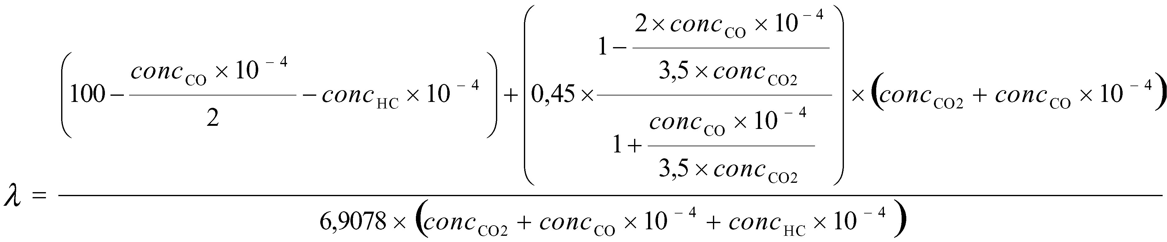
where
|
A/Fst
|
=
|
stoichiometric air/fuel ratio (kg/kg)
|
|
λ
|
=
|
relative air/fuel ratio
|
|
concCO2
|
=
|
dry CO2 concentration ( %)
|
|
concCO
|
=
|
dry CO concentration (ppm)
|
|
concHC
|
=
|
HC concentration (ppm)
|
Note: The calculation refers to a diesel fuel with a H/C ratio equal to 1,8.
The air flowmeter shall meet the accuracy specifications in Table 3, the CO2 analyser used shall meet the specifications of clause 1.4.1, and the total system shall meet the accuracy specifications for the exhaust gas flow.
Optionally, air to fuel ratio measurement equipment, such as a zirconia type sensor, may be used for the measurement of the relative air to fuel ratio in accordance with the specifications of clause 1.4.4.
1.2.6. Total dilute exhaust gas flow
When using a full flow dilution system, the total flow of the dilute exhaust (GTOTW) shall be measured with a PDP or CFV or SSV (Annex VI, Section 1.2.1.2) The accuracy shall conform to the provisions of Annex III, Appendix 2, Section 2.2.
1.3. Accuracy
The calibration of all measurement instruments shall be traceable to national or international standards and comply with the requirements listed in Table 3.
Table 3 — Accuracy of measuring instruments
|
No
|
Measuring instrument
|
Accuracy
|
|
1
|
Engine speed
|
± 2 % of reading or ± 1 % of engine's max. value whichever is larger
|
|
2
|
Torque
|
± 2 % of reading or ± 1 % of engine's max. value whichever is larger
|
|
3
|
Fuel consumption
|
± 2 % of engine's max. value
|
|
4
|
Air consumption
|
± 2 % of reading or ± 1 % of engine's max. value whichever is larger
|
|
5
|
Exhaust gas flow
|
± 2,5 % of reading or ± 1,5 % of engine's max. value whichever is larger
|
|
6
|
Temperatures ≤ 600 K
|
± 2 K absolute
|
|
7
|
Temperatures > 600 K
|
± 1 % of reading
|
|
8
|
Exhaust gas pressure
|
± 0,2 kPa absolute
|
|
9
|
Intake air depression
|
± 0,05 kPa absolute
|
|
10
|
Atmospheric pressure
|
± 0,1 kPa absolute
|
|
11
|
Other pressures
|
± 0,1 kPa absolute
|
|
12
|
Absolute humidity
|
± 5 % of reading
|
|
13
|
Dilution air flow
|
± 2 % of reading
|
|
14
|
Diluted exhaust gas flow
|
± 2 % of reading
|
1.4. Determination of the gaseous components
1.4.1. General analyser specifications
The analysers shall have a measuring range appropriate for the accuracy required to measure the concentrations of the exhaust gas components (section1.4.1.1). It is recommended that the analysers be operated in such a way that the measured concentration falls between 15 % and 100 % of full scale.
If the full scale value is 155 ppm (or ppm C) or less or if read-out systems (computers, data loggers) that provide sufficient accuracy and resolution below 15 % of full scale are used, concentrations below 15 % of full scale are also acceptable. In this case, additional calibrations are to be made to ensure the accuracy of the calibration curves – Annex III, Appendix 2, section 1.5.5.2.
The electromagnetic compatibility (EMC) of the equipment shall be on a level as to minimise additional errors.
1.4.1.1. Measurement error
The analyser shall not deviate from the nominal calibration point by more than ± 2 % of the reading or ± 0,3 % of full scale, whichever is larger.
NOTE: For the purpose of this standard, accuracy is defined as the deviation of the analyser reading from the nominal calibration values using a calibration gas (≡ true value)
1.4.1.2. Repeatability
The repeatability, defined as 2,5 times the standard deviation of 10 repetitive responses to a given calibration or span gas, must be no greater than ± 1 % of full scale concentration for each range used above 155 ppm (or ppm C) or ± 2 % of each range used below 155 ppm (or ppm C).
1.4.1.3. Noise
The analyser peak-to-peak response to zero and calibration or span gases over any 10-second period shall not exceed 2 % of full scale on all ranges used.
1.4.1.4. Zero drift
The zero drift during a one-hour period shall be less than 2 % of full scale on the lowest range used. The zero response is defined as the mean response, including noise, to a zero gas during a 30-second time interval.
1.4.1.5. Span drift
The span drift during a one-hour period shall be less than 2 % of full scale on the lowest range used. Span is defined as the difference between the span response and the zero response. The span response is defined as the mean response, including noise, to a span gas during a 30-second time interval.
1.4.2. Gas drying
The optional gas drying device must have a minimal effect on the concentration of the measured gases. Chemical dryers are not an acceptable method of removing water from the sample.
1.4.3. Analysers
Sections 1.4.3.1 to 1.4.3.5 of this Appendix describe the measurement principles to be used. A detailed description of the measurement systems is given in Annex VI.
The gases to be measured shall be analysed with the following instruments. For non-linear analysers, the use of linearising circuits is permitted.
1.4.3.1. Carbon monoxide (CO) analysis
The carbon monoxide analyser shall be of the non-dispersive infra-red (NDIR) absorption type.
1.4.3.2. Carbon dioxide (CO2) analysis
The carbon dioxide analyser shall be of the non-dispersive infra-red (NDIR) absorption type.
1.4.3.3. Hydrocarbon (HC) analysis
The hydrocarbon analyser shall be of the heated flame ionization detector (HFID) type with detector, valves, pipework, etc, heated so as to maintain a gas temperature of 463 K (190 °C) ± 10 K.
1.4.3.4. Oxides of nitrogen (NOx) analysis
The oxides of nitrogen analyser shall be of the chemiluminescent detector (CLD) or heated chemiluminescent detector (HCLD) type with a NO2/NO converter, if measured on a dry basis. If measured on a wet basis, a HCLD with converter maintained above 328 K (55 °C) shall be used, provided the water quench check (Annex III, Appendix 2, section 1.9.2.2) is satisfied.
For both CLD and HCLD, the sampling path shall be maintained at a wall temperature of 328 K to 473 K (55 to 200 °C) up to the converter for dry measurement, and up to the analyser for wet measurement.
1.4.4. Air to fuel measurement
The air to fuel measurement equipment used to determine the exhaust gas flow as specified in section 1.2.5 shall be a wide range air to fuel ratio sensor or lambda sensor of Zirconia type.
The sensor shall be mounted directly on the exhaust pipe where the exhaust gas temperature is high enough to eliminate water condensation.
The accuracy of the sensor with incorporated electronics shall be within:
± 5 % of reading 2 ≤ λ < 5
To fulfil the accuracy specified above, the sensor shall be calibrated as specified by the instrument manufacturer.
1.4.5. Sampling for gaseous emissions
The gaseous emissions sampling probes must be fitted at least 0,5 m or three times the diameter of the exhaust pipe — whichever is the larger — upstream of the exit of the exhaust gas system as far as applicable and sufficiently close to the engine as to ensure an exhaust gas temperature of at least 343 K (70 °C) at the probe.
In the case of a multi-cylinder engine with a branched exhaust manifold, the inlet of the probe shall be located sufficiently far downstream so as to ensure that the sample is representative of the average exhaust emissions from all cylinders. In multi-cylinder engines having distinct groups of manifolds, such as in a ‘V’-engine configuration, it is permissible to acquire a sample from each group individually and calculate an average exhaust emission. Other methods which have been shown to correlate with the above methods may be used. For exhaust emissions calculation the total exhaust mass flow of the engine must be used.
If the composition of the exhaust gas is influenced by any exhaust after-treatment system, the exhaust sample must be taken upstream of this device in the tests of stage I and downstream of this device in the tests of stage II. When a full flow dilution system is used for the determination of the particulates, the gaseous emissions may also be determined in the diluted exhaust gas. The sampling probes shall be close to the particulate sampling probe in the dilution tunnel (Annex VI, section 1.2.1.2, DT and Section 1.2.2, PSP). CO and CO2 may optionally be determined by sampling into a bag and subsequent measurement of the concentration in the sampling bag.
1.5. Determination of the particulates
The determination of the particulates requires a dilution system. Dilution may be accomplished by a partial flow dilution system or a full flow dilution system. The flow capacity of the dilution system shall be large enough to completely eliminate water condensation in the dilution and sampling systems, and maintain the temperature of the diluted exhaust gas between 315 K (42 °C) and 325 K (52 °C) immediately upstream of the filter holders. De-humidifying the dilution air before entering the dilution system is permitted, if the air humidity is high. Dilution air pre-heating above the temperature limit of 303 K (30 °C) is recommended, if the ambient temperature is below 293 K (20 °C). However, the diluted air temperature must not exceed 325 K (52 °C) prior to the introduction of the exhaust in the dilution tunnel.
Note: For steady-state procedure, the filter temperature may be kept at or below the maximum temperature of 325 K (52 °C) instead of respecting the temperature range of 42 to 52 °C.
For a partial flow dilution system, the particulate sampling probe must be fitted close to and upstream of the gaseous probe as defined in Section 4.4 and in accordance with Annex VI, section 1.2.1.1, figure 4-12 EP and SP.
The partial flow dilution system has to be designed to split the exhaust stream into two fractions, the smaller one being diluted with air and subsequently used for particulate measurement. From that it is essential that the dilution ratio be determined very accurately. Different splitting methods can be applied, whereby the type of splitting used dictates to a significant degree the sampling hardware and procedures to be used (Annex VI, section 1.2.1.1).
To determine the mass of the particulates, a particulate sampling system, particulate sampling filters, a microgram balance and a temperature and humidity controlled weighing chamber are required.
For particulate sampling, two methods may be applied:
— the single filter method uses one pair of filters (1.5.1.3 of this Appendix) for all modes of the test cycle. Considerable attention must be paid to sampling times and flows during the sampling phase of the test. However, only one pair of filters will be required for the test cycle,
— the multiple filter method dictates that one pair of filters (section 1.5.1.3 of this Appendix) is used for each of the individual modes of the test cycle. This method allows more lenient sample procedures but uses more filters.
1.5.1. Particulate sampling filters
1.5.1.1. Filter specification
Fluorocarbon coated glass fibre filters or fluorocarbon based membrane filters are required for certification tests. For special applications different filter materials may be used. All filter types shall have a 0,3 μm DOP (di-octylphthalate) collection efficiency of at least 99 % at a gas face velocity between 35 and 100 cm/s. When performing correlation tests between laboratories or between a manufacturer and an approval authority, filters of identical quality must be used.
1.5.1.2. Filter size
Particulate filters must have a minimum diameter of 47 mm (37 mm stain diameter). Larger diameter filters are acceptable (section 1.5.1.5).
1.5.1.3. Primary and back-up filters
The diluted exhaust shall be sampled by a pair of filters placed in series (one primary and one back-up filter) during the test sequence. The back-up filter shall be located no more than 100 mm downstream of, and shall not be in contact with, the primary filter. The filters may be weighed separately or as a pair with the filters placed stain side to stain side.
1.5.1.4. Filter face velocity
A gas face velocity through the filter of 35 to 100 cm/s shall be achieved. The pressure drop increase between the beginning and the end of the test shall be no more than 25 kPa.
1.5.1.5. Filter loading
The recommended minimum filter loadings for the most common filter sizes are shown in the following table. For larger filter sizes, the minimum filter loading shall be 0,065 mg/1 000 mm2 filter area.
|
Filter diameter
(mm)
|
Recommended stain diameter
(mm)
|
Recommended minimum loading
(mg)
|
|
47
|
37
|
0,11
|
|
70
|
60
|
0,25
|
|
90
|
80
|
0,41
|
|
110
|
100
|
0,62
|
For the multiple filter method, the recommended minimum filter loading for the sum of all filters shall be the product of the appropriate value above and the square root of the total number of modes.
1.5.2. Weighing chamber and analytical balance specifications
1.5.2.1. Weighing chamber conditions
The temperature of the chamber (or room) in which the particulate filters are conditioned and weighed shall be maintained to within 295 K (22 °C) ± 3 K during all filter conditioning and weighing. The humidity shall be maintained to a dew point of 282,5 (9,5 °C) ± 3 K and a relative humidity of 45 ± 8 %.
1.5.2.2. Reference filter weighing
The chamber (or room) environment shall be free of any ambient contaminants (such as dust) that would settle on the particulate filters during their stabilisation. Disturbances to weighing room specifications as outlined in section 1.5.2.1 will be allowed if the duration of the disturbances does not exceed 30 minutes. The weighing room should meet the required specifications prior to personnel entrance into the weighing room. At least two unused reference filters or reference filter pairs shall be weighed within four hours of, but preferably at the same time as the sample filter (pair) weighing. They shall be the same size and material as the sample filters.
If the average weight of the reference filters (reference filter pairs) changes between sample filter weighing by more than 10μg, then all sample filters shall be discarded and the emissions test repeated.
If the weighing room stability criteria outlined in section 1.5.2.1 is not met, but the reference filter (pair) weighing meet the above criteria, the engine manufacturer has the option of accepting the sample filter weights or voiding the tests, fixing the weighing room control system and re-running the test.
1.5.2.3. Analytical balance
The analytical balance used to determine the weights of all filters shall have a precision (standard deviation) of 2 μg and a resolution of 1 μg (1 digit = 1 μg) specified by the balance manufacturer.
1.5.2.4. Elimination of static electricity effects
To eliminate the effects of static electricity, the filters shall be neutralised prior to weighing, for example, by a Polonium neutraliser or a device of similar effect.
1.5.3. Additional specifications for particulate measurement
All parts of the dilution system and the sampling system from the exhaust pipe up to the filter holder, which are in contact with raw and diluted exhaust gas, must be designed to minimise deposition or alteration of the particulates. All parts must be made of electrically conductive materials that do not react with exhaust gas components, and must be electrically grounded to prevent electrostatic effects.
2. MEASUREMENT AND SAMPLING PROCEDURES (NRTC TEST)
2.1. Introduction
Gaseous and particulate components emitted by the engine submitted for testing shall be measured by the methods of Annex VI. The methods of Annex VI describe the recommended analytical systems for the gaseous emissions (Section 1.1) and the recommended particulate dilution and sampling systems (Section 1.2).
2.2. Dynamometer and test cell equipment
The following equipment shall be used for emission tests of engines on engine dynamometers:
2.2.1. Engine dynamometer
An engine dynamometer shall be used with adequate characteristics to perform the test cycle described in Appendix 4 to this Annex. The instrumentation for torque and speed measurement shall allow the measurement of the power within the given limits. Additional calculations may be necessary. The accuracy of the measuring equipment must be such that the maximum tolerances of the figures given in Table 3 are not exceeded.
2.2.2. Other instruments
Measuring instruments for fuel consumption, air consumption, temperature of coolant and lubricant, exhaust gas pressure and intake manifold depression, exhaust gas temperature, air intake temperature, atmospheric pressure, humidity and fuel temperature shall be used, as required. These instruments shall satisfy the requirements given in Table 3:
Table 3 — Accuracy of measuring instruments
|
No.
|
Measuring instrument
|
accuracy
|
|
1
|
Engine speed
|
± 2 % of reading or ± 1 % of engine's max. value, whichever is larger
|
|
2
|
Torque
|
± 2 % of reading or ± 1 % of engine's max. value, whichever is larger
|
|
3
|
Fuel consumption
|
± 2 % of engine's max. value
|
|
4
|
Air consumption
|
± 2 % of reading or ± 1 % of engine's max. value, whichever is larger
|
|
5
|
Exhaust gas flow
|
± 2,5 % of reading or ± 1,5 % of engine's max. value, whichever is larger
|
|
6
|
Temperatures ≤ 600 K
|
± 2 K absolute
|
|
7
|
Temperatures > 600 K
|
± 1 % of reading
|
|
8
|
Exhaust gas pressure
|
± 0,2 kPa absolute
|
|
9
|
Intake air depression
|
± 0,05 kPa absolute
|
|
10
|
Atmospheric pressure
|
± 0,1 kPa absolute
|
|
11
|
Other pressures
|
± 0,1 kPa absolute
|
|
12
|
Absolute humidity
|
± 5 % of reading
|
|
13
|
Dilution air flow
|
± 2 % of reading
|
|
14
|
Diluted exhaust gas flow
|
± 2 % of reading
|
2.2.3. Raw exhaust gas flow
For calculating the emissions in the raw exhaust gas and for controlling a partial flow dilution system, it is necessary to know the exhaust gas mass flow rate. For determining the exhaust mass flow rate, either of the methods described below may be used.
For the purpose of emissions calculation, the response time of either method described below shall be equal to or less than the requirement for the analyser response time, as defined in Appendix 2, Section 1.11.1.
For the purpose of controlling a partial flow dilution system, a faster response is required. For partial flow dilution systems with online control, a response time of ≤ 0,3 s is required. For partial flow dilution systems with look ahead control based on a pre-recorded test run, a response time of the exhaust flow measurement system of ≤ 5 s with a rise time of ≤ 1 s is required. The system response time shall be specified by the instrument manufacturer. The combined response time requirements for exhaust gas flow and partial flow dilution system are indicated in Section 2.4.
Direct measurement method
Direct measurement of the instantaneous exhaust flow may be done by systems, such as:
— pressure differential devices, like flow nozzle, (for details see ISO 5167: 2000)
Precautions shall be taken to avoid measurement errors, which will impact emission value errors. Such precautions include the careful installation of the device in the engine exhaust system according to the instrument manufacturers' recommendations and to good engineering practice. Especially, engine performance and emissions must not be affected by the installation of the device.
The flowmeters shall meet the accuracy specifications of Table 3.
Air and fuel measurement method
This involves measurement of the airflow and the fuel flow with suitable flowmeters. The calculation of the instantaneous exhaust gas flow is as follows:
GEXHW
= GAIRW
+ GFUEL
(for wet exhaust mass)
The flowmeters shall meet the accuracy specifications of Table 3, but shall also be accurate enough to also meet the accuracy specifications for the exhaust gas flow.
Tracer measurement method
This involves measurement of the concentration of a tracer gas in the exhaust.
A known amount of an inert gas (e.g. pure helium) shall be injected into the exhaust gas flow as a tracer. The gas is mixed and diluted by the exhaust gas, but must not react in the exhaust pipe. The concentration of the gas shall then be measured in the exhaust gas sample.
In order to ensure complete mixing of the tracer gas, the exhaust gas sampling probe shall be located at least 1 m or 30 times the diameter of the exhaust pipe, whichever is larger, downstream of the tracer gas injection point. The sampling probe may be located closer to the injection point if complete mixing is verified by comparing the tracer gas concentration with the reference concentration when the tracer gas is injected upstream of the engine.
The tracer gas flow rate shall be set so that the tracer gas concentration at engine idle speed after mixing becomes lower than the full scale of the trace gas analyser.
The calculation of the exhaust gas flow is as follows:
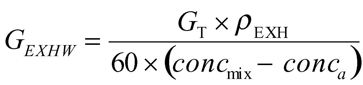
where
|
GEXHW
|
=
|
instantaneous exhaust mass flow (kg/s)
|
|
GT
|
=
|
tracer gas flow (cm3/min)
|
|
conc
mix
|
=
|
instantaneous concentration of the tracer gas after mixing (ppm)
|
|
ρEXH
|
=
|
density of the exhaust gas (kg/m3)
|
|
conc
a
|
=
|
background concentration of the tracer gas in the intake air (ppm)
|
The background concentration of the tracer gas (conc
a) may be determined by averaging the background concentration measured immediately before the test run and after the test run.
When the background concentration is less than 1 % of the concentration of the tracer gas after mixing (conc
mix.) at maximum exhaust flow, the background concentration may be neglected.
The total system shall meet the accuracy specifications for the exhaust gas flow, and shall be calibrated according to Appendix 2, paragraph 1.11.2.
Air flow and air to fuel ratio measurement method
This involves exhaust mass calculation from the airflow and the air to fuel ratio. The calculation of the instantaneous exhaust gas mass flow is as follows:
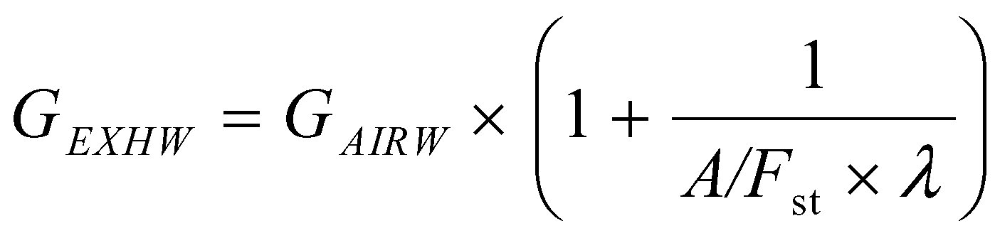

where
|
A/Fst
|
=
|
stoichiometric air/fuel ratio (kg/kg)
|
|
λ
|
=
|
relative air/fuel ratio
|
|
concCO2
|
=
|
dry CO2 concentration ( %)
|
|
concCO
|
=
|
dry CO concentration (ppm)
|
|
concHC
|
=
|
HC concentration (ppm)
|
Note: The calculation refers to a diesel fuel with a H/C ratio equal to 1,8.
The air flowmeter shall meet the accuracy specifications in Table 3, the CO2 analyser used shall meet the specifications of section 2.3.1, and the total system shall meet the accuracy specifications for the exhaust gas flow.
Optionally, air to fuel ratio measurement equipment, such as a zirconia type sensor, may be used for the measurement of the excess air ratio in accordance with the specifications of section 2.3.4.
2.2.4. Diluted exhaust gas flow
For calculation of the emissions in the diluted exhaust gas, it is necessary to know the diluted exhaust gas mass flow rate. The total diluted exhaust gas flow over the cycle (kg/test) shall be calculated from the measurement values over the cycle and the corresponding calibration data of the flow measurement device (V
0 for PDP, K
V for CFV, C
d for SSV): the corresponding methods described in Appendix 3, section 2.2.1 shall be used. If the total sample mass of particulates and gaseous pollutants exceeds 0,5 % of the total CVS flow, the CVS flow shall be corrected or the particulate sample flow shall be returned to the CVS prior to the flow measuring device.
2.3. Determination of the gaseous components
2.3.1. General analyser specifications
The analysers shall have a measuring range appropriate for the accuracy required to measure the concentrations of the exhaust gas components (section 1.4.1.1). It is recommended that the analysers be operated in such a way that the measured concentration falls between 15 and 100 % of full scale.
If the full scale value is 155 ppm (or ppm C) or less, or if read-out systems (computers, data loggers) that provide sufficient accuracy and resolution below 15 % of full scale are used, concentrations below 15 % of full scale are also acceptable. In this case, additional calibrations are to be made to ensure the accuracy of the calibration curves – Annex III, Appendix 2, section 1.5.5.2.
The electromagnetic compatibility (EMC) of the equipment shall be of a level such as to minimise additional errors.
2.3.1.1. Measurement error
The analyser shall not deviate from the nominal calibration point by more than ± 2 % of the reading or ± 0,3 % of full scale, whichever is larger.
Note: For the purpose of this standard, accuracy is defined as the deviation of the analyser reading from the nominal calibration values using a calibration gas (≡ true value).
2.3.1.2. Repeatability
The repeatability, defined as 2,5 times the standard deviation of 10 repetitive responses to a given calibration or span gas, must be no greater than ± 1 % of full scale concentration for each range used above 155 ppm (or ppm C) or ± 2 % for each range used below 155 ppm (or ppm C).
2.3.1.3. Noise
The analyser peak-to-peak response to zero and calibration or span gases over any 10-second period shall not exceed 2 % of full scale on all ranges used.
2.3.1.4. Zero drift
The zero drift during a one-hour period shall be less than 2 % of full scale on the lowest range used. The zero response is defined as the mean response, including noise, to a zero gas during a 30-second time interval.
2.3.1.5. Span drift
The span drift during a one-hour period shall be less than 2 % of full scale on the lowest range used. Span is defined as the difference between the span response and the zero response. The span response is defined as the mean response, including noise, to a span gas during a 30-second time interval.
2.3.1.6. Rise time
For raw exhaust gas analysis, the rise time of the analyser installed in the measurement system shall not exceed 2,5 s.
NOTE: Only evaluating the response time of the analyser alone will not clearly define the suitability of the total system for transient testing. Volumes, and especially dead volumes, through out the system will not only affect the transportation time from the probe to the analyser, but also affect the rise time. Also transport times inside of an analyser would be defined as analyser response time, like the converter or water traps inside of a NOx analysers. The determination of the total system response time is described in Appendix 2, Section 1.11.1.
2.3.2. Gas drying
Same specifications as for NRSC test cycle apply (Section 1.4.2) as described here below.
The optional gas drying device must have a minimal effect on the concentration of the measured gases. Chemical dryers are not an acceptable method of removing water from the sample.
2.3.3. Analysers
Same specifications as for NRSC test cycle apply (Section 1.4.3) as described here below.
The gases to be measured shall be analysed with the following instruments. For non-linear analysers, the use of linearising circuits is permitted.
2.3.3.1. Carbon monoxide (CO) analysis
The carbon monoxide analyser shall be of the non-dispersive infra-red (NDIR) absorption type.
2.3.3.2. Carbon dioxide (CO2) analysis
The carbon dioxide analyser shall be of the non-dispersive infra-red (NDIR) absorption type.
2.3.3.3. Hydrocarbon (HC) analysis
The hydrocarbon analyser shall be of the heated flame ionization detector (HFID) type with detector, valves, pipework, etc, heated so as to maintain a gas temperature of 463K (190 °C) ± 10 K.
2.3.3.4. Oxides of nitrogen (NOx) analysis
The oxides of nitrogen analyser shall be of the chemiluminescent detector (CLD) or heated chemiluminescent detector (HCLD) type with a NO2/NO converter, if measured on a dry basis. If measured on a wet basis, a HCLD with converter maintained above 328 K (55 °C shall be used, provided the water quench check (Annex III, Appendix 2, section 1.9.2.2) is satisfied.
For both CLD and HCLD, the sampling path shall be maintained at a wall temperature of 328K to 473 K (55 to 200 °C) up to the converter for dry measurement, and up to the analyser for wet measurement.
2.3.4. Air to fuel measurement
The air to fuel measurement equipment used to determine the exhaust gas flow as specified in section 2.2.3 shall be a wide range air to fuel ratio sensor or lambda sensor of Zirconia type.
The sensor shall be mounted directly on the exhaust pipe where the exhaust gas temperature is high enough to eliminate water condensation.
The accuracy of the sensor with incorporated electronics shall be within:
± 5 % of reading 2 ≤ λ < 5
To fulfil the accuracy specified above, the sensor shall be calibrated as specified by the instrument manufacturer.
2.3.5. Sampling of gaseous emissions
2.3.5.1. Raw exhaust gas flow
For calculation of the emissions in the raw exhaust gas the same specifications as for NRSC test cycle apply (Section 1.4.4), as described here below.
The gaseous emissions sampling probes must be fitted at least 0,5 m or three times the diameter of the exhaust pipe — whichever is the larger — upstream of the exit of the exhaust gas system as far as applicable and sufficiently close to the engine as to ensure an exhaust gas temperature of at least 343 K (70 °C) at the probe.
In the case of a multicylinder engine with a branched exhaust manifold, the inlet of the probe shall be located sufficiently far downstream so as to ensure that the sample is representative of the average exhaust emissions from all cylinders. In multicylinder engines having distinct groups of manifolds, such as in a ‘V’-engine configuration, it is permissible to acquire a sample from each group individually and calculate an average exhaust emission. Other methods which have been shown to correlate with the above methods may be used. For exhaust emissions calculation the total exhaust mass flow of the engine must be used.
If the composition of the exhaust gas is influenced by any exhaust after-treatment system, the exhaust sample must be taken upstream of this device in the tests of stage I and downstream of this device in the tests of stage II.
2.3.5.2. Diluted exhaust gas flow
If a full flow dilution system is used, the following specifications apply.
The exhaust pipe between the engine and the full flow dilution system shall conform to the requirements of Annex VI.
The gaseous emissions sample probe(s) shall be installed in the dilution tunnel at a point where the dilution air and exhaust gas are well mixed, and in close proximity to the particulates sampling probe.
Sampling can generally be done in two ways:
— the pollutants are sampled into a sampling bag over the cycle and measured after completion of the test,
— the pollutants are sampled continuously and integrated over the cycle; this method is mandatory for HC and NOx.
The background concentrations shall be sampled upstream of the dilution tunnel into a sampling bag, and shall be subtracted from the emissions concentration according to Appendix 3, Section 2.2.3.
2.4. Determination of the particulates
Determination of the particulates requires a dilution system. Dilution may be accomplished by a partial flow dilution system or a full flow dilution system. The flow capacity of the dilution system shall be large enough to completely eliminate water condensation in the dilution and sampling systems, and maintain the temperature of the diluted exhaust gas between 315 K (42 °C) and 325 K (52 °C) immediately upstream of the filter holders. De-humidifying the dilution air before entering the dilution system is permitted, if the air humidity is high. Dilution air pre-heating above the temperature limit of 303 K (30 °C) is recommended if the ambient temperature is below 293 K (20 °C). However, the diluted air temperature must not exceed 325 K (52 °C) prior to the introduction of the exhaust in the dilution tunnel.
The particulate sampling probe shall be installed in close proximity to the gaseous emissions sampling probe, and the installation shall comply with the provisions of Section 2.3.5.
To determine the mass of the particulates, a particulate sampling system, particulate sampling filters, microgram balance, and a temperature and humidity controlled weighing chamber, are required.
Partial flow dilution system specifications
The partial flow dilution system has to be designed to split the exhaust stream into two fractions, the smaller one being diluted with air and subsequently used for particulate measurement. For this it is essential that the dilution ratio be determined very accurately. Different splitting methods can be applied, whereby the type of splitting used dictates to a significant degree the sampling hardware and procedures to be used (Annex VI, section 1.2.1.1).
For the control of a partial flow dilution system, a fast system response is required. The transformation time for the system shall be determined by the procedure described in Appendix 2, Section 1.11.1.
If the combined transformation time of the exhaust flow measurement (see previous section) and the partial flow system is less than 0,3 s, online control may be used. If the transformation time exceeds 0,3 s, look ahead control based on a pre-recorded test run must be used. In this case, the rise time shall be ≤ 1 s and the delay time of the combination ≤ 10 s.
The total system response shall be designed as to ensure a representative sample of the particulates, GSE
, proportional to the exhaust mass flow. To determine the proportionality, a regression analysis of GSE
versus GEXHW
shall be conducted on a minimum 5 Hz data acquisition rate, and the following criteria shall be met:
— the correlation coefficient r of the linear regression between GSE and GEXHW shall be not less than 0,95,
— the standard error of estimate of GSE on GEXHW shall not exceed 5 % of GSE maximum.
— GSE intercept of the regression line shall not exceed ± 2 % of GSE maximum.
Optionally, a pre-test may be run, and the exhaust mass flow signal of the pre-test be used for controlling the sample flow into the particulate system (look-ahead control). Such a procedure is required if the transformation time of the particulate system, t
50,P or/and the transformation time of the exhaust mass flow signal, t
50,F are > 0,3 s. Acorrect control of the partial dilution system is obtained, if the time trace of GEXHW
,pre of the pre-test, which controls GSE, is shifted by a ‘look-ahead’ time of t
50,P + t
50,F.
For establishing the correlation between GSE
and GEXHW
the data taken during the actual test shall be used, with GEXHW
time aligned by t50,F relative to GSE
(no contribution from t
50,P to the time alignment). That is, the time shift between GEXHW
and GSE
is the difference in their transformation times that were determined in Appendix 2, Section 2.6.
For partial flow dilution systems, the accuracy of the sample flow GSE
is of special concern, if not measured directly, but determined by differential flow measurement:
GSE
= GTOTW
— GDILW
In this case an accuracy of ± 2 % for GTOTW
and GDILW
is not sufficient to guarantee acceptable accuracies of GSE.
If the gas flow is determined by differential flow measurement, the maximum error of the difference shall be such that the accuracy of GSE
is within ± 5 % when the dilution ratio is less than 15. It can be calculated by taking root-mean-square of the errors of each instrument.
Acceptable accuracies of GSE
can be obtained by either of the following methods:
(a) The absolute accuracies of GTOTW and GDILW are ± 0,2 % which guarantees an accuracy of GSE of ≤ 5 % at a dilution ratio of 15. However, greater errors will occur at higher dilution ratios.
(b) Calibration of GDILW relative to GTOTW is carried out such that the same accuracies for GSE as in (a) are obtained. For the details of such a calibration see Appendix 2, Section 2.6.
(c) The accuracy of GSE is determined indirectly from the accuracy of the dilution ratio as determined by a tracer gas, e.g. CO2. Again, accuracies equivalent to method (a) for GSE are required.
(d) The absolute accuracy of GTOTW and GDILW is within ± 2 % of full scale, the maximum error of the difference between GTOTW and GDILW is within 0,2 %, and the linearity error is within ± 0,2 % of the highest GTOTW observed during the test.
2.4.1. Particulate sampling filters
2.4.1.1. Filter specification
Fluorocarbon coated glass fibre filters or fluorocarbon based membrane filters are required for certification tests. For special applications different filter materials may be used. All filter types shall have a 0,3 μm DOP (di-octylphthalate) collection efficiency of at least 99 % at a gas face velocity between 35 and 100 cm/s. When performing correlation tests between laboratories or between a manufacturer and an approval authority, filters of identical quality must be used.
2.4.1.2. Filter size
Particulate filters must have a minimum diameter of 47 mm (37 mm stain diameter). Larger diameter filters are acceptable (section 2.4.1.5).
2.4.1.3. Primary and back-up filters
The diluted exhaust shall be sampled by a pair of filters placed in series (one primary and one back-up filter) during the test sequence. The back-up filter shall be located no more than 100mm downstream of, and shall not be in contact with, the primary filter. The filters may be weighed separately or as a pair with the filters placed stain side to stain side.
2.4.1.4. Filter face velocity
A gas face velocity through the filter of 35 to 100 cm/s shall be achieved. The pressure drop increase between the beginning and the end of the test shall be no more than 25 kPa.
2.4.1.5. Filter loading
The recommended minimum filter loadings for the most common filter sizes are shown in the following table. For larger filter sizes, the minimum filter loading shall be 0,065 mg/1 000 mm2 filter area.
|
Filter diameter
(mm)
|
Recommended stain diameter
(mm)
|
Recommended minimum loading
(mg)
|
|
47
|
37
|
0,11
|
|
70
|
60
|
0,25
|
|
90
|
80
|
0,41
|
|
110
|
100
|
0,62
|
2.4.2. Weighing chamber and analytical balance specifications
2.4.2.1. Weighing chamber conditions
The temperature of the chamber (or room) in which the particulate filters are conditioned and weighed shall be maintained to within 295 K (22 °C) ± 3 K during all filter conditioning and weighing. The humidity shall be maintained to a dewpoint of 282,5 (9,5 °C) ± 3 K and a relative humidity of 45 ± 8 %.
2.4.2.2. Reference filter weighing
The chamber (or room) environment shall be free of any ambient contaminants (such as dust) that would settle on the particulate filters during their stabilisation. Disturbances to weighing room specifications as outlined in section 2.4.2.1 will be allowed if the duration of the disturbances does not exceed 30 minutes. The weighing room should meet the required specifications prior to personnel entrance into the weighing room. At least two unused reference filters or reference filter pairs shall be weighed within four hours of, but preferably at the same time as the sample filter (pair) weighing. They shall be the same size and material as the sample filters.
If the average weight of the reference filters (reference filter pairs) changes between sample filter weighing by more than 10 μg, then all sample filters shall be discarded and the emissions test repeated.
If the weighing room stability criteria outlined in section 2.4.2.1 are not met, but the reference filter (pair) weighing meet the above criteria, the engine manufacturer has the option of accepting the sample filter weights or voiding the tests, fixing the weighing room control system and re-running the test.
2.4.2.3. Analytical balance
The analytical balance used to determine the weights of all filters shall have a precision (standard deviation) of 2 μg and a resolution of 1 μg (1 digit = 1 μg) specified by the balance manufacturer.
2.4.2.4. Elimination of static electricity effects
To eliminate the effects of static electricity, the filters shall be neutralised prior to weighing, for example, by a Polonium neutraliser or a device having similar effect.
2.4.3. Additional specifications for particulate measurement
All parts of the dilution system and the sampling system from the exhaust pipe up to the filter holder, which are in contact with raw and diluted exhaust gas, must be designed to minimise deposition or alteration of the particulates. All parts must be made of electrically conductive materials that do not react with exhaust gas components, and must be electrically grounded to prevent electrostatic effects.
Appendix 2
CALIBRATION PROCEDURE (NRSC, NRTC (
22
))
▼B
1. CALIBRATION OF THE ANALYTICAL INSTRUMENTS
1.1. Introduction
Each analyzer shall be calibrated as often as necessary to fulfil the accuracy requirements of this standard. The calibration method that shall be used is described in this paragraph for the analysers indicated in Appendix 1, section 1.4.3.
1.2. Calibration gases
The shelf life of all calibration gases must be respected.
The expiry date of the calibration gases stated by the manufacturer shall be recorded.
1.2.1. Pure gases
The required purity of the gases is defined by the contamination limits given below. The following gases must be available for operation:
— purified nitrogen
— (contamination ≤ 1 ppm C, ≤ 1 ppm CO, ≤ 400 ppm CO2, ≤ 0,1 ppm NO)
— purified oxygen
— (purity > 99,5 % vol O2)
— hydrogen-helium mixture
— (40 ± 2 % hydrogen, balance helium)
— (contamination ≤ 1 ppm C, ≤ 400 ppm
►M1
CO2
◄ )
— purified synthetic air
— (contamination ≤ 1 ppm C, ≤ 1 ppm CO, ≤ 400 ppm CO2, ≤ 0,1 ppm NO)
— (oxygen content between 18 – 21 % vol)
1.2.2. Calibration and span gases
Mixture of gases having the following chemical compositions shall be available:
— C3H8 and purified synthetic air (see section 1.2.1)
— CO and purified nitrogen
— NO and purified nitrogen (the amount of NO2 contained in this calibration gas must not exceed 5 % of the NO content)
— O2 and purified nitrogen
— CO2 and purified nitrogen
— CH4 and purified synthetic air
— C2H6 and purified synthetic air
Note: other gas combinations are allowed provided the gases do not react with one another.
The true concentration of a calibration and span gas must be within ± 2 % of the nominal value. All concentrations of calibration gas shall be given on a volume basis (volume percent or volume ppm).
The gases used for calibration and span may also be obtained by means of a gas divider, diluting with purified N2 or with purified synthetic air. The accuracy of the mixing device must be such that the concentration of the diluted calibration gases may be determined to within ± 2 %.
▼M3
This accuracy implies that primary gases used for blending shall be known to have an accuracy of at least ± 1 %, traceable to national or international gas standards. The verification shall be performed at between 15 and 50 % of full scale for each calibration incorporating a blending device. An additional verification may be performed using another calibration gas, if the first verification has failed.
Optionally, the blending device may be checked with an instrument which by nature is linear, e.g. using NO gas with a CLD. The span value of the instrument shall be adjusted with the span gas directly connected to the instrument. The blending device shall be checked at the used settings and the nominal value shall be compared to the measured concentration of the instrument. This difference shall in each point be within ± 1 % of the nominal value.
Other methods may be used based on good engineering practice and with the prior agreement of the parties involved.
Note: A precision gas divider of accuracy is within ± 1 %, is recommended for establishing the accurate analyser calibration curve. The gas divider shall be calibrated by the instrument manufacturer.
▼B
1.3. Operating procedure for analysers and sampling system
The operating procedure for analysers shall follow the start-up and operating instructions of the instrument manufacturer. The minimum requirements given in sections 1.4 to 1.9 shall be included.
1.4. Leakage test
A system leakage test shall be performed. The probe shall be disconnected from the exhaust system and the end plugged. The analyser pump shall be switched on. After an initial stabilization period all flow meters should read zero. If not, the sampling lines shall be checked and the fault corrected. The maximum allowable leakage rate on the vacuum side shall be 0,5 % of the in-use flow rate for the portion of the system being checked. The analyser flows and bypass flows may be used to estimate the in-use flow rates.
Another method is the introduction of a concentration step change at the beginning of the sampling line by switching from zero to span gas.
If after an adequate period of time the reading shows a lower concentration compared to the introduced concentration, this points to calibration or leakage problems.
1.5. Calibration procedure
1.5.1. Instrument assembly
The instrument assembly shall be calibrated and calibration curves checked against standard gases. The same gas flow rates shall be used as when sampling exhaust.
1.5.2. Warming-up time
The warming-up time should be according to the recommendations of the manufacturer. If not specified, a minimum of two Hours is recommended for warming-up the analysers.
1.5.3. NDIR and HFID analyser
The NDIR analyser shall be tuned, as necessary, and the combustion flame of the HFID analyser shall be optimized (section 1.8.1).
1.5.4. Calibration
Each normally used operating range shall be calibrated.
Using purified synthetic air (or nitrogen), the CO, CO2, Nox, HC and O2 analysers shall be set at zero.
The appropriate calibration gases shall be introduced to the analysers, the values recorded, and the calibration curve established according to section 1.5.6.
The zero setting shall be re-checked and the calibration procedure repeated, if necessary.
1.5.5. Establishment of the calibration curve
1.5.5.1. General guidelines
►M3
►C1
The analyser calibration curve is established by at least six calibration points (excluding zero) spaced as uniformly as possible. ◄
◄ The highest nominal concentration must be equal to or higher than 90 % of full scale.
The calibration curve is calculated by the method of least squares. If the resulting polynomial degree is greater than three, the number of calibration points (zero included) must be at least equal to this polynomial degree plus two.
▼M3
The calibration curve must not differ by more than ± 2 % from the nominal value of each calibration point and by more than ± 0,3 % of full scale at zero.
▼B
From the calibration curve and the calibration points, it is possible to verify that the calibration has been carried out correctly. The different characteristic parameters of the analyser must be indicated, particularly:
— the date of carrying out the calibration.
1.5.5.2. Calibration below 15 % of full scale
The analyser calibration curve is established by at least ten calibration points (excluding zero) spaced so that 50 % of the calibration points is below 10 % of full scale.
The calibration curve is calculated by the method of least squares.
▼M3
The calibration curve must not differ by more than ± 4 % from the nominal value of each calibration point and by more than ± 0,3 % of full scale at zero.
▼B
1.5.5.3. Alternative methods
If it can be shown that alternative technology (e.g. computer, electronically controlled range switch, etc.) can give equivalent accuracy, then these alternatives may be used.
1.6. Verification of the calibration
Each normally used operating range shall be checked prior to each analysis in accordance with the following procedure.
The calibration is checked by using a zero gas and a span gas whose nominal value is more than 80 % of full scale of the measuring range.
If, for the two points considered, the value found does not differ by more than ± 4 % of full scale from the declared reference value, the adjustment parameters may be modified. Should this not be the case, a new calibration curve shall be established in accordance with section 1.5.4.
1.7. Efficiency test of the NOx converter
The efficiency of the converter used for the conversion of NO2 into NO is tested as given in sections 1.7.1 to 1.7.8 (Figure 1).
1.7.1. Test set-up
Using the test set-up as shown in Figure 1 (see also Appendix 1, section 1.4.3.5) and the procedure below, the efficiency of converters can be tested by means of an ozonator.
 Figure 1
Schematic of NO2 converter efficiency device
Figure 1
Schematic of NO2 converter efficiency device
1.7.2. Calibration
The CLD and the HCLD shall be calibrated in the most common operating range following the manufacturer's specifications using zero and span gas (the NO content of which must amount to about 80 % of the operating range and the NO2 concentration of the gas mixture to less than 5 % of the NO concentration). The NOx analyser must be in the NO mode so that the span gas does not pass through the converter. The indicated concentration has to be recorded.
1.7.3. Calculation
The efficiency of the NOx converter is calculated as follows:

|
(a)
|
NOx concentration according to section 1.7.6;
|
|
(b)
|
NOx concentration according to section 1.7.7;
|
|
(c)
|
NO concentration according to section 1.7.4;
|
|
(d)
|
NO concentration according to section 1.7.5.
|
1.7.4. Adding of oxygen
Via a T-fitting, oxygen or zero air is added continuously to the gas flow until the concentration indicated is about 20 % less than the indicated calibration concentration given in section 1.7.2 (The analyser is in the NO mode.)
The indicated concentration (c) shall be recorded. The ozonator is kept de-activated throughout the process.
1.7.5. Activation of the ozonator
The ozonator is now activated to generate enough ozone to bring the NO concentration down to about 20 % (minimum 10 %) of the calibration concentration given in section 1.7.2. The indicated concentration (d) shall be recorded. (The analyser is in the NO mode.)
1.7.6. NOx mode
The NO analyser is then switched to the NOx mode so that the gas mixture (consisting of NO, NO2, O2 and N2) now passes through the converter. The indicated concentration (a) shall be recorded. (The analyser is in the NOx mode.)
1.7.7. De-activation of the ozonator
The ozonator is now de-activated. The mixture of gases described in section 1.7.6 passes through the converter into the detector. The indicated concentration (b) shall be recorded. (The analyser is in the NOx mode.)
1.7.8. NO mode
Switched to NO mode with the ozonator de-activated, the flow of oxygen or synthetic air is also shut off. The NOx reading of the analyser shall not deviate by more than ± 5 % from the value measured according to section 1.7.2 (The analyser is in the NO mode.)
1.7.9. Test interval
The efficiency of the converter must be tested prior to each calibration of the NOx analyser.
1.7.10. Efficiency requirement
The efficiency of the converter shall not be less than 90 %, but a higher efficiency of 95 % is strongly recommended.
Note: If, with the analyser in the most common range, the ozonator cannot give a reduction from 80 % to 20 % according to section 1.7.5, then the highest range which will give the reduction shall be used.
1.8. Adjustment of the FID
1.8.1. Optimization of the detector response
The HFID must be adjusted as specified by the instrument manufacturer. A propane in air span gas should be used to optimize the response on the most common operating range.
With the fuel and air flow rates set at the manufacturer's recommendations, a 350 ± 75 ppm C span gas shall be introduced to the analyser. The response at a given fuel flow shall be determined from the difference between the span gas response and the zero gas response. The fuel flow shall be incrementally adjusted above and below the manufacturer's specification. The span and zero response at these fuel flows shall be recorded. The difference between the span and zero response shall be plotted and the fuel flow adjusted to the rich side of the curve.
1.8.2. Hydrocarbon response factors
The analyser shall be calibrated using propane in air and purified synthetic air, according to section 1.5.
Response factors shall be determined when introducing an analyser into service and after major service intervals. The response factor (Rf) for a particular hydrocarbon species is the ratio of the FID C1 reading to the gas concentration in the cylinder expressed by ppm C1.
The concentration of the test gas must be at a level to give a response of approximately 80 % of full scale. The concentration must be known to an accuracy of ± 2 % in reference to a gravimetric standard expressed in volume. In addition, the gas cylinder must be pre-conditioned for 24 hours at a temperature of 298 K (25 oC) ± 5 K.
The test gases to be used and the recommended relative response factor ranges are as follows:
|
— methane and purified synthetic air:
|
1,00 ≤ Rf ≤ 1,15
|
|
— propylene and purified synthetic air:
|
0,90 ≤ Rf ≤ 1,1
|
|
— toluene and purified synthetic air:
|
0,90 ≤ Rf ≤ 1,10
|
These values are relative to the response factor (Rf) of 1,00 for propane and purified synthetic air.
1.8.3. Oxygen interference check
▼M3
The oxygen interference check shall be determined when introducing an analyser into service and after major service intervals.
A range shall be chosen where the oxygen interference check gases will fall within the upper 50 %. The test shall be conducted with the oven temperature set as required.
1.8.3.1. Oxygen interference gases
Oxygen interference check gases shall contain propane with 350 ppmC ÷ 75 ppmC hydrocarbon. The concentration value shall be determined to calibration gas tolerances by chromatographic analysis of total hydrocarbons plus impurities or by dynamic blending. Nitrogen shall be the predominant diluent with the balance oxygen. Blends required for Diesel engine testing are:
|
O2 concentration
|
Balance
|
|
21 (20 to 22)
|
Nitrogen
|
|
10 (9 to 11
|
Nitrogen
|
|
5 (4 to 6)
|
Nitrogen
|
1.8.3.2. Procedure
(a) The analyser shall be zeroed.
(b) The analyser shall be spanned with the 21 % oxygen blend.
(c) The zero response shall be rechecked. If it has changed more than 0,5 % of full scale clauses (a) and (b) shall be repeated.
(d) The 5 % and 10 % oxygen interference check gases shall be introduced.
(e) The zero response shall be rechecked. If it has changed more than ± 1 % of full scale, the test shall be repeated.
(f) The oxygen interference (%O2I) shall be calculated for each mixture in (d) as follows:

|
A
|
=
|
hydrocarbon concentration (ppmC) of the span gas used in (b)
|
|
B
|
=
|
hydrocarbon concentration (ppmC) of the oxygen interference check gases used in (d)
|

|
D
|
=
|
percent of full scale analyser response due to A.
|
(g) The % of oxygen interference (%O2I) shall be less than ± 3,0 % for all required oxygen interference check gases prior to testing.
(h) If the oxygen interference is greater than ± 3,0 %, the air flow above and below the manufacturer's specifications shall be incrementally adjusted, repeating clause 1.8.1 for each flow.
(i) If the oxygen interference is greater than ± 3,0 % after adjusting the air flow, the fuel flow and thereafter the sample flow shall be varied, repeating clause 1.8.1 for each new setting.
(j) If the oxygen interference is still greater than ± 3,0 %, the analyser, FID fuel, or burner air shall be repaired or replaced prior to testing. This clause shall then be repeated with the repaired or replaced equipment or gases.
▼B
1.9. Interference effects with NDIR and CLD analysers
Gases present in the exhaust other than the one being analysed can interfere with the reading in several ways. Positive interference occurs in NDIR instruments where the interfering gas gives the same effect as the gas being measured, but to a lesser degree. Negative interference occurs in NDIR instruments by the interfering gas broadening the absorption band of the measured gas, and in CLD instruments by the interfering gas quenching the radiation. The interference checks in sections 1.9.1 and 1.9.2 shall be performed prior to an analyser's initial use and after major service intervals.
1.9.1. CO analyser interference check
Water and CO2 can interfere with the CO analyser performance. Therefore a CO2 span gas having a concentration of 80 to 100 % of full scale of the maximum operating range used during testing shall be bubbled through water at room temperature and the analyser response recorded. The analyser response must not be more than 1 % of full scale for ranges equal to or above 300 ppm or more than 3 ppm for ranges below 300 ppm.
1.9.2. NOx analyser quench checks
The two gases of concern for CLD (and HCLD) analysers are CO2 and water vapour. Quench responses of these gases are proportional to their concentrations, and therefore require test techniques to determine the quench at the highest expected concentrations experienced during testing.
1.9.2.1. CO2 quench check
A CO2 span gas having a concentration of 80 to 100 % of full scale of the maximum operating range shall be passed through the NDIR analyser and the CO2 value recorded as A. It shall then be diluted approximately 50 % with NO span gas and passed through the NDIR and (H)CLD with the CO2 and NO values recorded as B and C, respectively. The CO2 shall be shut off and only the NO span gas be passed through the (H)CLD and the NO value recorded as D.
The quench shall be calculated as follows:
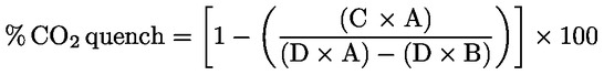
and must not be greater than 3 % of full scale.
where:
|
A
|
:
|
undiluted CO2 concentration measured with NDIR %
|
|
B
|
:
|
diluted CO2 concentration measured with NDIR %
|
|
C
|
:
|
diluted NO concentration measured with CLD ppm
|
|
D
|
:
|
undiluted NO concentration measured with CLD ppm
|
▼M1
1.9.2.2. Water quench check
▼M3
This check applies to wet gas concentration measurements only. Calculation of water quench must consider dilution of the NO span gas with water vapour and scaling of water vapour concentration of the mixture to that expected during testing. A NO span gas having a concentration of 80 to 100 % of full scale to the normal operating range shall be passed through the (H)CLD and the NO value recorded as D. The NO gas shall be bubbled through water at room temperature and passed through the (H)CLD and NO value recorded as C. The water temperature shall be determined and recorded as F. The mixture's saturation vapour pressure that corresponds to the bubbler water temperature (F) shall be determined and recorded as G. The water vapour concentration (in %) of the mixture shall be calculated as follows:
▼M1

and recorded as H. The expected diluted NO span gas (in water vapour) concentration shall be calculated as follows:
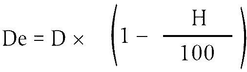
▼M3
and recorded as De. For diesel exhaust, the maximum exhaust water vapour concentration (in %) expected during testing shall be estimated, under the assumption of a fuel atom H/C ratio of 1,8 to 1, from the maximum CO2 concentration in the exhaust gas or from the undiluted CO2 span gas concentration (A, as measured in section 1.9.2.1) as follows:
▼M1
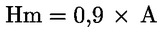
and recorded as Hm.
The water quench shall be calculated as follows:
 and must not be greater than 3 % of full scale.
De : expected diluted NO concentration (ppm)
C : diluted NO concentration (ppm)
Hm : maximum water vapour concentration (%)
H : actual water vapour concentration (%)
NB: It is important that the NO span gas contains minimal NO2 concentration for this check, since obsorption of NO2 in water has not been accounted for in the quench calculations.
▼B
1.10. Calibration intervals
The analysers shall be calibrated according to section 1.5 at least every three months or whenever a system repair or change is made that could influence calibration.
▼M3
1.11. Additional calibration requirements for raw exhaust measurements over NRTC test
1.11.1. Response time check of the analytical system
The system settings for the response time evaluation shall be exactly the same as during measurement of the test run (i.e. pressure, flow rates, filter settings on the analysers and all other response time influences). The response time determination shall be done with gas switching directly at the inlet of the sample probe. The gas switching shall be done in less than 0,1 second. The gases used for the test shall cause a concentration change of at least 60 % FS.
The concentration trace of each single gas component shall be recorded. The response time is defined as the difference in time between the gas switching and the appropriate change of the recorded concentration. The system response time (t90) consists of the delay time to the measuring detector and the rise time of the detector. The delay time is defined as the time from the change (t0) until the response is 10 % of the final reading (t10). The rise time is defined as the time between 10 and 90 % response of the final reading (t90 — t10).
For time alignment of the analyser and exhaust flow signals in the case of raw measurement, the transformation time is defined as the time from the change (t0) until the response is 50 % of the final reading (t50).
The system response time shall be ≤ 10 seconds with a rise time ≤ 2,5 seconds for all limited components (CO, NOx, HC) and all ranges used.
1.11.2. Calibration of tracer gas analyser for exhaust flow measurement
The analyser for measurement of the tracer gas concentration, if used, shall be calibrated using the standard gas.
The calibration curve shall be established by at least 10 calibration points (excluding zero) spaced so that a half of the calibration points are placed between 4 to 20 % of analyser's full scale and the rest are in between 20 to 100 % of the full scale. The calibration curve is calculated by the method of least squares.
The calibration curve shall not differ by more than ± 1 % of the full scale from the nominal value of each calibration point, in the range from 20 to 100 % of the full scale. It shall also not differ by more than ± 2 % from the nominal value in the range from 4 to 20 % of the full scale.
The analyser shall be set at zero and spanned prior to the test run using a zero gas and a span gas whose nominal value is more than 80 % of the analyser full scale.
▼B
2. CALIBRATION OF THE PARTICULATE MEASURING SYSTEM
2.1. Introduction
Each component shall be calibrated as often as necessary to fulfil the accuracy requirements of this standard. The calibration method to be used is described in this section for the components indicated in Annex III, Appendix 1, section 1.5 and Annex V.
2.2. Flow measurement
▼M3
The calibration of gas flow-meters or flow measurement instrumentation shall be traceable to national and/or international standards.
The maximum error of the measured value shall be within ± 2 % of reading.
For partial flow dilution systems, the accuracy of the sample flow GSE
is of special concern, if not measured directly, but determined by differential flow measurement:
GSE
= GTOTW
— GDILW
In this case an accuracy of ± 2 % for GTOTW
and GDILW
is not sufficient to guarantee acceptable accuracies of GSE.
If the gas flow is determined by differential flow measurement, the maximum error of the difference shall be such that the accuracy of GSE
is within ± 5 % when the dilution ratio is less than 15. It can be calculated by taking root-mean-square of the errors of each instrument.
▼B
2.3. Checking the dilution ratio
When using particulate sampling systems without EGA (Annex V, section 1.2.1.1), the dilution ratio shall be checked for each new engine installation with the engine running and the use of either the CO2 or NOx concentration measurements in the raw and dilute exhaust.
The measured dilution ratio shall be within ± 10 % of the calculated dilution ratio from CO2 or NOx concentration measurement.
2.4. Checking the partial flow conditions
The range of the exhaust gas velocity and the pressure oscillations shall be checked and adjusted according to the requirements of Annex V, section 1.2.1.1, EP, if applicable.
2.5. Calibration intervals
The flow measurement instrumentation shall be calibrated at least every three months, or whenever a system change is made that could influence calibration.
▼M3
2.6. Additional calibration requirements for partial flow dilution systems
2.6.1 Periodical calibration
If the sample gas flow is determined by differential flow measurement the flow meter or the flow measurement instrumentation shall be calibrated by one of the following procedures, such that the probe flow GSE into the tunnel fulfils the accuracy requirements of Appendix I section 2.4:
The flow meter for GDILW is connected in series to the flow meter for GTOTW
, the difference between the two flow meters is calibrated for at least five set points with flow values equally spaced between the lowest GDILW value used during the test and the value of GTOTW
used during the test The dilution tunnel may be bypassed.
A calibrated mass flow device is connected in series to the flowmeter for GTOTW
and the accuracy is checked for the value used for the test. Then the calibrated mass flow device is connected in series to the flow meter for GDILW, and the accuracy is checked for at least five settings corresponding to the dilution ratio between 3 and 50, relative to GTOTW
used during the test.
The transfer tube TT is disconnected from the exhaust, and a calibrated flow measuring device with a suitable range to measure GSE is connected to the transfer tube. Then GTOTW
is set to the value used during the test, and GDILW is sequentially set to at least five values corresponding to dilution ratios q between 3 and 50. Alternatively, a special calibration flow path may be provided, in which the tunnel is bypassed, but the total and dilution air flow through the corresponding meters are maintained as in the actual test.
A tracer gas is fed into the transfer tube TT. This tracer gas may be a component of the exhaust gas, like CO2 or NOx. After dilution in the tunnel the tracer gas component is measured. This shall be carried out for five dilution ratios between 3 and 50. The accuracy of the sample flow is determined from the dilution ration q:
GSE = GTOTW
/q
The accuracies of the gas analysers shall be taken into account to guarantee the accuracy of GSE.
2.6.2. Carbon flow check
A carbon flow check using actual exhaust is strongly recommended for detecting measurement and control problems and verifying the proper operation of the partial flow dilution system. The carbon flow check should be run at least each time a new engine is installed, or something significant is changed in the test cell configuration.
The engine shall be operated at peak torque load and speed or any other steady-state mode that produces 5 % or more of CO2. The partial flow sampling system shall be operated with a dilution factor of about 15 to 1.
2.6.3. Pre-test check
A pre-test check shall be performed within two hours before the test run in the following way:
The accuracy of the flow meters shall be checked by the same method as used for calibration for at least two points, including flow values of GDILW that correspond to dilution ratios between five and 15 for the GTOTW
value used during the test.
If it can be demonstrated by records of the calibration procedure described above that the flow meter calibration is stable over a longer period of time, the pre-test check may be omitted.
2.6.4. Determination of the transformation time
The system settings for the transformation time evaluation shall be exactly the same as during measurement of the test run. The transformation time shall be determined by the following method:
An independent reference flowmeter with a measurement range appropriate for the probe flow shall be put in series with and closely coupled to the probe. This flow meter shall have a transformation time of less than 100 ms for the flow step size used in the response time measurement, with flow restriction sufficiently low not to affect the dynamic performance of the partial flow dilution system, and consistent with good engineering practice.
A step change shall be introduced to the exhaust flow (or air flow if exhaust flow is calculated) input of the partial flow dilution system, from a low flow to at least 90 % of full scale. The trigger for the step change should be the same one as that used to start the look-ahead control in actual testing. The exhaust flow step stimulus and the flowmeter response shall be recorded at a sample rate of at least 10 Hz.
From this data, the transformation time shall be determined for the partial flow dilution system, which is the time from the initiation of the step stimulus to the 50 % point of the flowmeter response. In a similar manner, the transformation times of the GSE signal of the partial flow dilution system and of the GEXHW
signal of the exhaust flow meter shall be determined. These signals are used in the regression checks performed after each test (Appendix I section 2.4).
The calculation shall be repeated for at least five rise-and-fall stimuli, and the results shall be averaged. The internal transformation time (< 100 ms) of the reference flowmeter shall be subtracted from this value. This is the ‘look-ahead’ value of the partial flow dilution system, which shall be applied in accordance with Appendix I section 2.4.
3. CALIBRATION OF THE CVS SYSTEM
3.1. General
The CVS system shall be calibrated by using an accurate flowmeter and means to change operating conditions.
The flow through the system shall be measured at different flow operating settings, and the control parameters of the system shall be measured and related to the flow.
Various type of flowmeters may be used, e.g. calibrated venturi, calibrated laminar flowmeter, calibrated turbine meter.
3.2. Calibration of the positive displacement pump (PDP)
All the parameters related to the pump shall be simultaneously measured along with the parameters related to a calibration venturi which is connected in series with the pump. The calculated flow rate (in m3/min at pump inlet, absolute pressure and temperature) shall be plotted against a correlation function which is the value of a specific combination of pump parameters. The linear equation which relates the pump flow and the correlation function shall be determined. If a CVS has a multiple speed drive, the calibration shall be performed for each range used.
Temperature stability shall be maintained during calibration.
Leaks in all the connections and ducting between the calibration venturi and the CVS pump shall be maintained lower than 0,3 % of the lowest flow point (highest restriction and lowest PDP speed point).
3.2.1. Data analysis
The air flowrate (Qs) at each restriction setting (minimum 6 settings) shall be calculated in standard m3/min from the flowmeter data using the manufacturer's prescribed method. The air flow rate shall then be converted to pump flow (V0) in m3/rev at absolute pump inlet temperature and pressure as follows
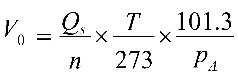
where,
|
Qs
|
=
|
air flow rate at standard conditions (101,3 kPa, 273 K) (m3/s)
|
|
T
|
=
|
temperature at pump inlet (K)
|
|
pA
|
=
|
absolute pressure at pump inlet (pB- p1) (kPa)
|
To account for the interaction of pressure variations at the pump and the pump slip rate, the correlation function (X0) between pump speed, pressure differential from pump inlet to pump outlet and absolute pump outlet pressure shall be calculated as follows:
where,

|
pA
|
=
|
absolute outlet pressure at pump outlet (kPa)
|
A linear least-square fit shall be performed to generate the calibration equation as follows:

D0 and m are the intercept and slope constants, respectively, describing the regression lines.
For a CVS system with multiple speeds, the calibration curves generated for the different pump flow ranges shall be approximately parallel, and the intercept values (D0) shall increase as the pump flow range decreases.
The values calculated by the equation shall be within ± 0,5 % of the measured value of V0. Values of m will vary from one pump to another. Particulate influx over time will cause the pump slip to decrease, as reflected by lower values for m. Therefore, calibration shall be performed at pump start-up, after major maintenance, and if the total system verification (section 3.5) indicates a change in the slip rate.
3.3. Calibration of the critical flow venturi (CFV)
Calibration of the CFV is based upon the flow equation for a critical venturi. Gas flow is a function of inlet pressure and temperature, as shown below:
where,
|
Kv
|
=
|
calibration coefficient
|
|
pA
|
=
|
absolute pressure at venturi inlet (kPa)
|
|
T
|
=
|
temperature at venturi inlet (K)
|
3.3.1. Data analysis
The air flow rate (Qs) at each restriction setting (minimum 8 settings) shall be calculated in standard m3/min from the flowmeter data using the manufacturer's prescribed method. The calibration coefficient shall be calculated from the calibration data for each setting as follows:

where,
|
Qs
|
=
|
air flow rate at standard conditions (101,3 kPa, 273 K) (m3/s)
|
|
T
|
=
|
temperature at the venturi inlet (K)
|
|
pA
|
=
|
absolute pressure at venturi inlet (kPa)
|
To determine the range of critical flow, Kv shall be plotted as a function of venturi inlet pressure. For critical (choked) flow, Kv will have a relatively constant value. As pressure decreases (vacuum increases), the venturi becomes unchoked and Kv decreases, which indicates that the CFV is operated outside the permissible range.
For a minimum of eight points in the region of critical flow, the average KV and the standard deviation shall be calculated. The standard deviation shall not exceed ± 0,3 % of the average KV
3.4. Calibration of the subsonic venturi (SSV)
Calibration of the SSV is based upon the flow equation for a subsonic venturi. Gas flow is a function of inlet pressure and temperature, pressure drop between the SSV inlet and throat, as shown below:

where,
|
A0
|
=
|
collection of constants and units conversions 
|
|
d
|
=
|
diameter of the SSV throat (m)
|
|
Cd
|
=
|
discharge coefficient of the SSV
|
|
PA
|
=
|
absolute pressure at venturi inlet (kPa)
|
|
T
|
=
|
temperature at the venturi inlet (K)
|
3.4.1. Data analysis
The air flow rate (QSSV) at each flow setting (minimum 16 settings) shall be calculated in standard m3/min from the flowmeter data using the manufacturer's prescribed method. The discharge coefficient shall be calculated from the calibration data for each setting as follows:

where,
|
QSSV
|
=
|
air flow rate at standard conditions (101,3 kPa, 273 K), m3/s
|
|
T
|
=
|
temperature at the venturi inlet, K
|
|
d
|
=
|
diameter of the SSV throat, m
|

To determine the range of subsonic flow, Cd shall be plotted as a function of Reynolds number, at the SSV throat. The Re at the SSV throat is calculated with the following formula:

where,
|
A1
|
=
|
a collection of constants and units conversions
|

|
QSSV
|
=
|
air flow rate at standard conditions (101,3 kPa, 273 K) (m3/s)
|
|
d
|
=
|
diameter of the SSV throat (m)
|
|
μ
|
=
|
absolute or dynamic viscosity of the gas, calculated with the following formula:
|

where:

Because QSSV is an input to the Re formula, the calculations must be started with an initial guess for QSSV or Cd of the calibration venturi, and repeated until QSSV converges. The convergence method must be accurate to 0,1 % or better.
For a minimum of sixteen points in the subsonic flow region, the calculated values of Cd from the resulting calibration curve fit equation must be within ± 0,5 % of the measured Cd for each calibration point.
3.5. Total system verification
The total accuracy of the CVS sampling system and analytical system shall be determined by introducing a known mass of a pollutant gas into the system while it is being operated in the normal manner. The pollutant is analysed, and the mass calculated according to Annex III, Appendix 3, section 2.4.1 except in the case of propane where a factor of 0,000472 is used in place of 0,000479 for HC. Either of the following two techniques shall be used.
3.5.1. Metering with a critical flow orifice
A known quantity of pure gas (propane) shall be fed into the CVS system through a calibrated critical orifice. If the inlet pressure is high enough, the flow rate, which is adjusted by means of the critical flow orifice, is independent of the orifice outlet pressure (critical flow). The CVS system shall be operated as in a normal exhaust emission test for about five to 10 minutes. A gas sample shall be analysed with the usual equipment (sampling bag or integrating method), and the mass of the gas calculated. The mass so determined shall be within ± 3 % of the known mass of the gas injected.
3.5.2. Metering by means of a gravimetric technique
The weight of a small cylinder filled with propane shall be determined with a precision of ± 0,01 g. For about five to 10 minutes, the CVS system shall be operated as in a normal exhaust emission test, while carbon monoxide or propane is injected into the system. The quantity of pure gas discharged shall be determined by means of differential weighing. A gas sample shall be analysed with the usual equipment (sampling bag or integrating method), and the mass of the gas calculated. The mass so determined shall be within ± 3 % of the known mass of the gas injected.
▼B
Appendix 3
▼M3
DATA EVALUATION AND CALCULATIONS
▼B
1. DATA EVALUATION AND CALCULATIONS — NRSC TEST
1.1. Gaseous emissions data evaluation
For the evaluation of the gaseous emissions, the chart reading of the last 60 seconds of each mode shall be averaged, and the average concentrations (conc) of HC, CO, NOx and CO2 if the carbon balance method is used, during each mode shall be determined from the average chart readings and the corresponding calibration data. A different type of recording can be used if it ensures an equivalent data acquisition.
The average background concentrations (concd) may be determined from the bag readings of the dilution air or from the continous (non-bag) background reading and the corresponding calibration data.
▼M3
1.2. Particulate emissions
For the evaluation of the particulates, the total sample masses (MSAM, i) through the filters shall be recorded for each mode. The filters shall be returned to the weighing chamber and conditioned for at least one hour, but not more than 80 hours, and then weighed. The gross weight of the filters shall be recorded and the tare weight (see section 3.1, Annex III) subtracted. The particulate mass (Mf for single filter method; Mf, i for the multiple filter method) is the sum of the particulate masses collected on the primary and back-up filters. If background correction is to be applied, the dilution air mass (MDIL) through the filters and the particulate mass (Md) shall be recorded. If more than one measurement was made, the quotient Md/MDIL must be calculated for each single measurement and the values averaged.
▼B
1.3. Calculation of the gaseous emissions
The finally reported test results shall be derived through the following steps:
▼M3
1.3.1. Determination of the exhaust gas flow
The exhaust gas flow rate (GEXHW,) shall be determined for each mode according to Annex III, Appendix 1, sections 1.2.1. to 1.2.3.
When using a full flow dilution system, the total dilute exhaust gas flow rate (GTOTW,) shall be determined for each mode according to Annex III, Appendix 1, section 1.2.4.
1.3.2. Dry/wet correction
Dry/wet correction (GEXHW,) shall be determined for each mode according to Annex III, Appendix 1, sections 1.2.1. to 1.2.3.
When applying GEXHW the measured concentration shall be converted to a wet basis according to the following formulae, if not already measured on a wet basis:
conc (wet) = kw × conc (dry)
For the raw exhaust gas:
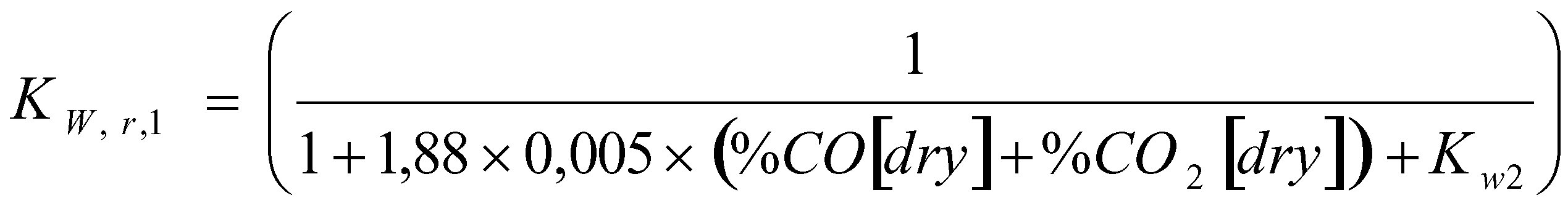
For the diluted gas:

or:
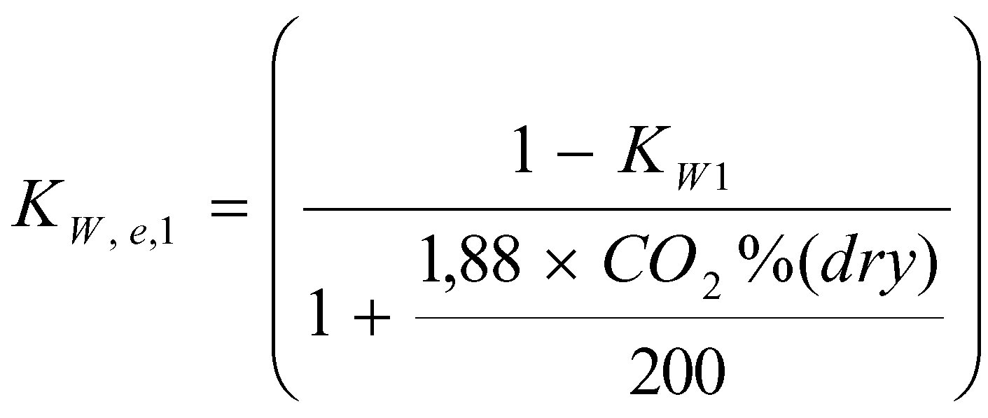
For the dilution air:
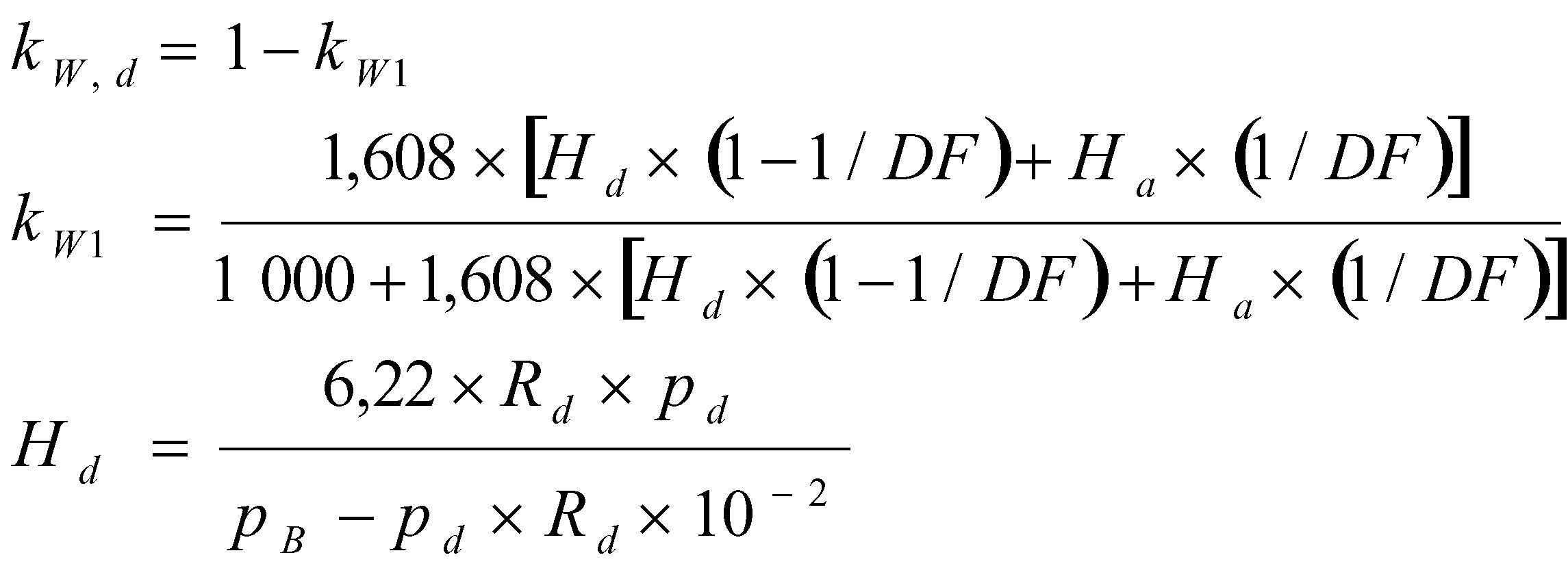
For the intake air (if different from the dilution air):

where:
|
Ha
|
:
|
absolute humidity of the intake air (g water per kg dry air)
|
|
Hd
|
:
|
absolute humidity of the dilution air (g water per kg dry air)
|
|
Rd
|
:
|
relative humidity of the dilution air ( %)
|
|
Ra
|
:
|
relative humidity of the intake air ( %)
|
|
pd
|
:
|
saturation vapour pressure of the dilution air (kPa)
|
|
pa
|
:
|
saturation vapour pressure of the intake air (kPa)
|
|
pB
|
:
|
total barometric pressure (kPa).
|
Note:
H
a and H
d may be derived from relative humidity measurement, as described above, or from dewpoint measurement, vapour pressure measurement or dry/wet bulb measurement using the generally accepted formulae.
1.3.3. Humidity correction for NOx
As the NOx emission depends on ambient air conditions, the NOx concentration shall be corrected for ambient air temperature and humidity by the factors KH given in the following formula:

where:
|
Ta
|
:
|
temperatures of the air in (K)
|
|
Ha
|
:
|
humidity of the intake air (g water per kg dry air):
|

where:
|
Ra
|
:
|
relative humidity of the intake air ( %)
|
|
pa
|
:
|
saturation vapour pressure of the intake air (kPa)
|
|
pB
|
:
|
total barometric pressure (kPa).
|
Note:
H
a may be derived from relative humidity measurement, as described above, or from dewpoint measurement, vapour pressure measurement or dry/wet bulb measurement using the generally accepted formulae.
1.3.4. Calculation of emission mass flow rates
The emission mass flow rates for each mode shall be calculated as follows:
(a) For the raw exhaust gas (
23
):
Gasmass = u × conc × GEXHW
(b) For the dilute exhaust gas (23) :
Gasmass = u × concc × GTOTW
where:
concc is the background corrected concentration

or:
DF=13,4/concCO2
The coefficients u - wet shall be used according to Table 4:
Table 4:
Values of the coefficients u - wet for various exhaust components
|
Gas
|
u
|
conc
|
|
NOx
|
0,001587
|
ppm
|
|
CO
|
0,000966
|
ppm
|
|
HC
|
0,000479
|
ppm
|
|
CO2
|
15,19
|
percent
|
The density of HC is based upon an average carbon to hydrogen ratio of 1:1,85.
1.3.5. Calculation of the specific emissions
The specific emission (g/kWh) shall be calculated for all individual components in the following way:

where Pi = Pm, i + PAE, i.
The weighting factors and the number of modes (n) used in the above calculation are according to Annex III, section 3.7.1.
1.4. Calculation of the particulate emission
The particulate emission shall be calculated in the following way:
1.4.1. Humidity correction factor for particulates
As the particulate emission of diesel engines depends on ambient air conditions, the particulate mass flow rate shall be corrected for ambient air humidity with the factor Kp given in the following formula:

where:
|
Ha
|
:
|
humidity of the intake air, gram of water per kg dry air
|

where:
|
Ra
|
:
|
relative humidity of the intake air (%)
|
|
pa
|
:
|
saturation vapour pressure of the intake air (kPa)
|
|
pB
|
:
|
total barometric pressure (kPa)
|
Note:
H
a may be derived from relative humidity measurement, as described above, or from dewpoint measurement, vapour pressure measurement or dry/wet bulb measurement using the generally accepted formulae
1.4.2. Partial flow dilution system
The final reported test results of the particulate emission shall be derived through the following steps. Since various types of dilution rate control may be used, different calculation methods for equivalent diluted exhaust gas mass flow rate GEDF apply. All calculations shall be based upon the average values of the individual modes (i) during the sampling period.
1.4.2.1. Isokinetic systems
GEDFW, i = GEXHW, i × qi

where r corresponds to the ratio of the cross sectional areas of the isokinetic probe Ap and exhaust pipe AT:

1.4.2.2. Systems with measurement of CO2 or NOx concentration
GEDFW, i = GEXHW, i × qi

where:
|
ConcE
|
=
|
wet concentration of the tracer gas in raw exhaust
|
|
ConcD
|
=
|
wet concentration of the tracer gas in the diluted exhaust
|
|
ConcA
|
=
|
wet concentration of the tracer gas in the dilution air
|
Concentrations measured on a dry basis shall be converted to a wet basis according to section 1.3.2.
1.4.2.3. Systems with CO2 measurement and carbon balance method
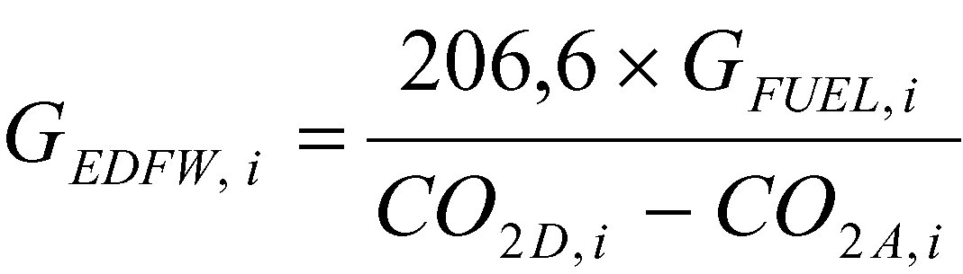
where:
|
CO2D
|
=
|
CO2 concentration of the diluted exhaust
|
|
CO2A
|
=
|
CO2 concentration of the dilution air
|
(concentrations in volume % on wet basis)
This equation is based upon the carbon balance assumption (carbon atoms supplied to the engine are emitted as CO2) and derived through the following steps:
GEDFW, i = GEXHW, i × qi
and:
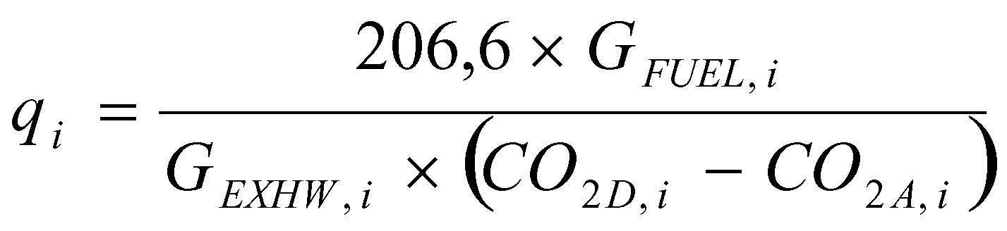
1.4.2.4. Systems with flow measurement
GEDFW, i = GEXHW, i × qi
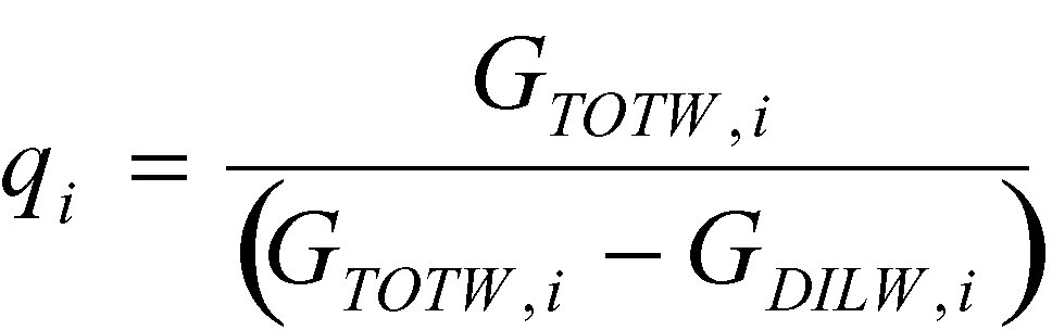
1.4.3. Full flow dilution system
The final reported test results of the particulate emission shall be derived through the following steps.
All calculations shall be based upon the average values of the individual modes (i) during the sampling period.
GEDFW, i = GTOTW, i
1.4.4. Calculation of the particulate mass flow rate
The particulate mass flow rate shall be calculated as follows:
For the single filter method:
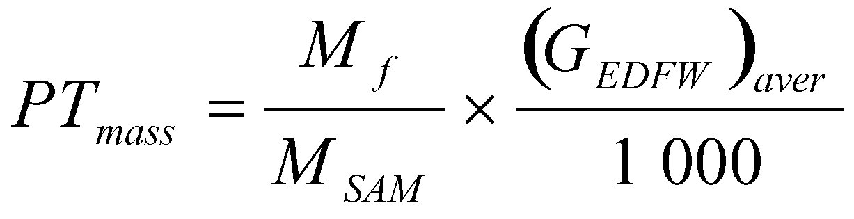
where:
(GEDFW)aver over the test cycle shall be determined by summation of the average values of the individual modes during the sampling period:

where i = 1, . . . n
For the multiple filter method:

where i = 1, . . . n
The particulate mass flow rate may be background corrected as follows:
For single filter method:

If more than one measurement is made, (Md/MDIL) shall be replaced with (Md/MDIL)aver

or:
DF=13,4/concCO2
For multiple filter method:

If more than one measurement is made, (Md/MDIL) shall be replaced with (Md/MDIL)aver

or:
DF= 13,4/concCO2
1.4.5. Calculation of the specific emissions
The specific emission of particulates PT (g/kWh) shall be calculated in the following way (
24
):
For the single filter method:

For the multiple filter method:
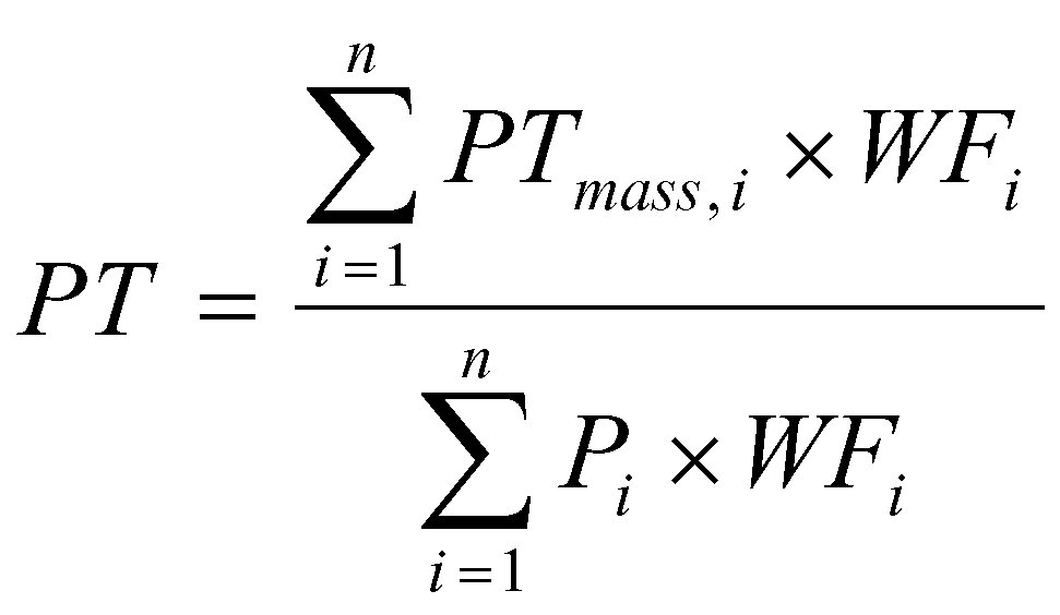
1.4.6. Effective weighting factor
For the single filter method, the effective weighting factor WFE, i for each mode shall be calculated in the following way:
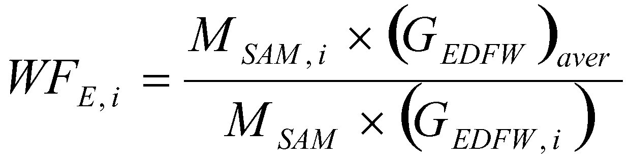
where i = l, . . . n.
The value of the effective weighting factors shall be within ± 0,005 (absolute value) of the weighting factors listed in Annex III, section 3.7.1.
▼M3
2. DATA EVALUATION AND CALCULATIONS (NRTC TEST)
The two following measurement principles that can be used for the evaluation of pollutant emissions over the NRTC cycle are described in this section:
— the gaseous components are measured in the raw exhaust gas on a real-time basis, and the particulates are determined using a partial flow dilution system,
— the gaseous components and the particulates are determined using a full flow dilution system (CVS system).
2.1. Calculation of gaseous emissions in the raw exhaust gas and of the particulate emissions with a partial flow dilution system
2.1.1. Introduction
The instantaneous concentration signals of the gaseous components are used for the calculation of the mass emissions by multiplication with the instantaneous exhaust mass flow rate. The exhaust mass flow rate may be measured directly, or calculated using the methods described in Annex III, Appendix 1, section 2.2.3 (intake air and fuel flow measurement, tracer method, intake air and air/fuel ratio measurement). Special attention shall be paid to the response times of the different instruments. These differences shall be accounted for by time aligning the signals.
For particulates, the exhaust mass flow rate signals are used for controlling the partial flow dilution system to take a sample proportional to the exhaust mass flow rate. The quality of proportionality is checked by applying a regression analysis between sample and exhaust flow as described in Annex III, Appendix 1, section 2.4.
2.1.2. Determination of the gaseous components
2.1.2.1. Calculation of mass emission
The mass of the pollutants Mgas
(g/test) shall be determined by calculating the instantaneous mass emissions from the raw concentrations of the pollutants, the u values from Table 4 (see also Section 1.3.4) and the exhaust mass flow, aligned for the transformation time and integrating the instantaneous values over the cycle. Preferably, the concentrations should be measured on a wet basis. If measured on a dry basis, the dry/wet correction as described here below shall be applied to the instantaneous concentration values before any further calculation is done.
Table 4: Values of the coefficients u — wet for various exhaust components
|
Gas
|
u
|
conc
|
|
NOx
|
0,001587
|
ppm
|
|
CO
|
0,000966
|
ppm
|
|
HC
|
0,000479
|
ppm
|
|
CO2
|
15,19
|
percent
|
The density of HC is based upon an average carbon to hydrogen ratio of 1:1,85.
The following formula shall be applied:

where
|
u
|
=
|
ratio between density of exhaust component and density of exhaust gas
|
|
conc
i
|
=
|
instantaneous concentration of the respective component in the raw exhaust gas (ppm)
|
|
GEXHW, i
|
=
|
instantaneous exhaust mass flow (kg/s)
|
|
f
|
=
|
data sampling rate (Hz)
|
|
n
|
=
|
number of measurements
|
For the calculation of NOx, the humidity correction factor k
H, as described here below, shall be used.
The instantaneously measured concentration shall be converted to a wet basis as described here below, if not already measured on a wet basis
2.1.2.2. Dry/wet correction
If the instantaneously measured concentration is measured on a dry basis, it shall be converted to a wet basis according to the following formulae:
conc
wet = k
W x conc
dry
where

with

where
|
conc
CO2
|
=
|
dry CO2 concentration (%)
|
|
conc
CO
|
=
|
dry CO concentration (%)
|
|
H
a
|
=
|
intake air humidity, (g water per kg dry air)
|

|
Ra
|
:
|
relative humidity of the intake air (%)
|
|
pa
|
:
|
saturation vapour pressure of the intake air (kPa)
|
|
pB
|
:
|
total barometric pressure (kPa)
|
Note:
H
a may be derived from relative humidity measurement, as described above, or from dewpoint measurement, vapour pressure measurement or dry/wet bulb measurement using the generally accepted formulae.
2.1.2.3. NOx correction for humidity and temperature
As the NOx emission depends on ambient air conditions, the NOx concentration shall be corrected for humidity and ambient air temperature with the factors given in the following formula:

with:
|
T
a
|
=
|
temperature of the intake air, K
|
|
H
a
|
=
|
humidity of the intake air, g water per kg dry air
|

where:
|
Ra
|
:
|
relative humidity of the intake air ( %)
|
|
pa
|
:
|
saturation vapour pressure of the intake air (kPa)
|
|
pB
|
:
|
total barometric pressure (kPa)
|
Note:
H
a may be derived from relative humidity measurement, as described above, or from dewpoint measurement, vapour pressure measurement or dry/wet bulb measurement using the generally accepted formulae.
▼M6
2.1.2.4.
Calculation of the specific emissions
The specific emissions (g/kWh) shall be calculated for each individual component in the following way:

where:
|
Mgas,cold
|
=
|
total mass of gaseous pollutant over the cold start cycle (g)
|
|
Mgas,hot
|
=
|
total mass of gaseous pollutant over the hot start cycle (g)
|
|
Wact,cold
|
=
|
actual cycle work over the cold start cycle as determined in Annex III section 4.6.2 (kWh)
|
|
Wact,hot
|
=
|
actual cycle work over the hot start cycle as determined in Annex III section 4.6.2 (kWh)
|
▼C1
2.1.3. Particulate determination
▼M6
2.1.3.1.
Calculation of mass emission
The particulate masses MPT,cold and MPT,hot (g/test) shall be calculated by either of the following methods:
(a)
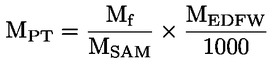
where
|
MPT
|
=
|
MPT,cold for the cold start cycle
|
|
MPT
|
=
|
MPT,hot for the hot start cycle
|
|
Mf
|
=
|
particulate mass sampled over the cycle (mg)
|
|
MEDFW
|
=
|
mass of equivalent diluted exhaust gas over the cycle (kg)
|
|
MSAM
|
=
|
mass of diluted exhaust gas passing the particulate collection filters (kg)
|
The total mass of equivalent diluted exhaust gas mass over the cycle shall be determined as follows:
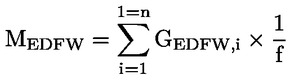


where
|
GEDFW,i
|
=
|
instantaneous equivalent diluted exhaust mass flow rate (kg/s)
|
|
GEXHW,i
|
=
|
instantaneous exhaust mass flow rate (kg/s)
|
|
qi
|
=
|
instantaneous dilution ratio
|
|
GTOTW,i
|
=
|
instantaneous diluted exhaust mass flow rate through dilution tunnel (kg/s)
|
|
GDILW,i
|
=
|
instantaneous dilution air mass flow rate (kg/s)
|
|
f
|
=
|
data sampling rate (Hz)
|
|
n
|
=
|
number of measurements
|
(b)

where
|
MPT
|
=
|
MPT,cold for the cold start cycle
|
|
MPT
|
=
|
MPT,hot for the hot start cycle
|
|
Mf
|
=
|
particulate mass sampled over the cycle (mg)
|
|
rs
|
=
|
average sample ratio over the test cycle
|
where

|
MSE
|
=
|
sampled exhaust mass over the cycle (kg)
|
|
MEXHW
|
=
|
total exhaust mass flow over the cycle (kg)
|
|
MSAM
|
=
|
mass of diluted exhaust gas passing the particulate collection filters (kg)
|
|
MTOTW
|
=
|
mass of diluted exhaust gas passing the dilution tunnel (kg)
|
NOTE: In case of the total sampling type system, MSAM and MTOTW are identical
▼C1
2.1.3.2. Particulate correction factor for humidity
As the particulate emission of diesel engines depends on ambient air conditions, the particulate concentration shall be corrected for ambient air humidity with the factor Kp given in the following formula.

where
|
Ha
|
=
|
humidity of the intake air in g water per kg dry air
|

|
Ra
|
:
|
relative humidity of the intake air (%)
|
|
pa
|
:
|
saturation vapour pressure of the intake air (kPa)
|
|
pB
|
:
|
total barometric pressure (kPa)
|
Note: Ha may be derived from relative humidity measurement, as described above, or from dewpoint measurement, vapour pressure measurement or dry/wet bulb measurement using the generally accepted formulae.
▼M6
2.1.3.3.
Calculation of the specific emissions
The specific emissions (g/kWh) shall be calculated for in the following way:

where
|
MPT,cold
|
=
|
particulate mass over the cold start cycle (g/test)
|
|
MPT,hot
|
=
|
particulate mass over the hot start cycle (g/test)
|
|
Kp, cold
|
=
|
humidity correction factor for particulate over the cold start cycle
|
|
Kp, hot
|
=
|
humidity correction factor for particulate over the hot start cycle
|
|
Wact, cold
|
=
|
actual cycle work over the cold start cycle as determined in section 4.6.2. of Annex III, (kWh)
|
|
Wact, hot
|
=
|
actual cycle work over the hot start cycle as determined in section 4.6.2. of Annex III, (kWh)
|
▼C1
2.2. Determination of gaseous and particulate components with a full flow dilution system
For calculation of the emissions in the diluted exhaust gas, it is necessary to know the diluted exhaust gas mass flow rate. The total diluted exhaust gas flow over the cycle MTOTW
(kg/test) shall be calculated from the measurement values over the cycle and the corresponding calibration data of the flow measurement device (V
0 for PDP, K
V for CFV, C
d for SSV): the corresponding methods described in section 2.2.1 may be used. If the total sample mass of particulates (MSAM
) and gaseous pollutants exceeds 0,5 % of the total CVS flow (MTOTW
), the CVS flow shall be corrected for MSAM
or the particulate sample flow shall be returned to the CVS prior to the flow measuring device.
2.2.1. Determination of the diluted exhaust gas flow
PDP-CVS system
The calculation of the mass flow over the cycle, if the temperature of the diluted exhaust is kept within ± 6 K over the cycle by using a heat exchanger, is as follows:
MTOTW
= 1,293 x V0 x NP x (pB - p1) x273/(101,3 x T)
where
|
MTOTW
|
=
|
mass of the diluted exhaust gas on wet basis over the cycle
|
|
V0
|
=
|
volume of gas pumped per revolution under test conditions (m3/rev)
|
|
NP
|
=
|
total revolutions of pump per test
|
|
pB
|
=
|
atmospheric pressure in the test cell (kPa)
|
|
p1
|
=
|
pressure drop below atmospheric at the pump inlet (kPa)
|
|
T
|
=
|
average temperature of the diluted exhaust gas at pump inlet over thecycle (K)
|
If a system with flow compensation is used (i.e. without heat exchanger), the instantaneous mass emissions shall be calculated and integrated over the cycle. In this case, the instantaneous mass of the diluted exhaust gas shall be calculated as follows:
MTOTW
,i = 1,293 × V0 × NP, i x (pB – p1) × 273 /(101,3 x T)
where
|
NP, i
|
=
|
total revolutions of pump per time interval
|
CFV-CVS system
The calculation of the mass flow over the cycle, if the temperature of the diluted exhaust gas is kept within ± 11 K over the cycle by using a heat exchanger, is as follows:
MTOTW
= 1,293 × t × Kv × pA/T0,5
where
|
MTOTW
|
=
|
mass of the diluted exhaust gas on wet basis over the cycle
|
|
KV
|
=
|
calibration coefficient of the critical flow venturi for standard conditions,
|
|
pA
|
=
|
absolute pressure at venturi inlet (kPa)
|
|
T
|
=
|
absolute temperature at venturi inlet (K)
|
If a system with flow compensation is used (i.e. without heat exchanger), the instantaneous mass emissions shall be calculated and integrated over the cycle. In this case, the instantaneous mass of the diluted exhaust gas shall be calculated as follows:
MTOTW
,i = 1,293 × Δti × KV × pA/T0,5
where
SSV-CVS system
The calculation of the mass flow over the cycle is as follows if the temperature of the diluted exhaust is kept within ± 11 K over the cycle by using a heat exchanger:
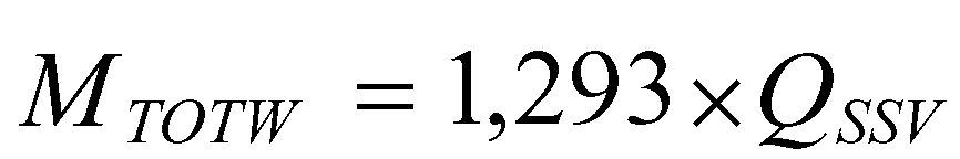
where

|
A0
|
=
|
collection of constants and units conversions = 0,006111 in SI units of 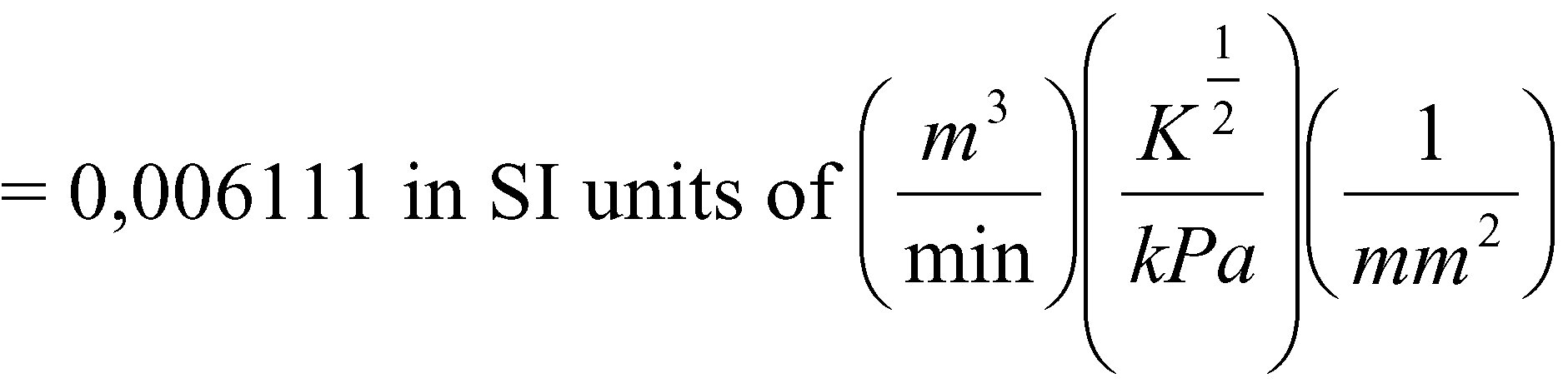
|
|
d
|
=
|
diameter of the SSV throat (m)
|
|
Cd
|
=
|
discharge coefficient of the SSV
|
|
PA
|
=
|
absolute pressure at venturi inlet (kPa)
|
|
T
|
=
|
temperature at the venturi inlet (K)
|

If a system with flow compensation is used (i.e. without heat exchanger), the instantaneous mass emissions shall be calculated and integrated over the cycle. In this case, the instantaneous mass of the diluted exhaust gas shall be calculated as follows:

where

The real time calculation shall be initialised with either a reasonable value for Cd, such as 0.98, or a reasonable value of Qssv. If the calculation is initialised with Qssv, the initial value of Qssv shall be used to evaluate Re.
During all emissions tests, the Reynolds number at the SSV throat must be in the range of Reynolds numbers used to derive the calibration curve developed in Appendix 2 section 3.2.
2.2.2. NOx correction for humidity
As the NOx emission depends on ambient air conditions, the NOx concentration shall be corrected for ambient air humidity with the factors given in the following formulae.

where
|
Ta
|
=
|
temperature of the air (K)
|
|
Ha
|
=
|
humidity of the intake air (g water per kg dry air)
|
in which,

|
Ra
|
=
|
relative humidity of the intake air (%)
|
|
pa
|
=
|
saturation vapour pressure of the intake air (kPa)
|
|
pB
|
=
|
total barometric pressure (kPa)
|
Note:
H
a may be derived from relative humidity measurement, as described above, or from dewpoint measurement, vapour pressure measurement or dry/wet bulb measurement using the generally accepted formulae.
2.2.3. Calculation of the emission mass flow
2.2.3.1. Systems with constant mass flow
For systems with heat exchanger, the mass of the pollutants MGAS (g/test) shall be determined from the following equation:
Mgaz = u × conc × MTOTW
where
|
u
|
=
|
ratio between density of the exhaust component and density of diluted exhaust gas, as reported in Table 4, point 2.1.2.1
|
|
conc
|
=
|
average background corrected concentrations over the cycle from integration (mandatory for NOx and HC) or bag measurement (ppm)
|
|
MTOTW
|
=
|
total mass of diluted exhaust gas over the cycle as determined in section 2.2.1 (kg)
|
As the NOx emission depends on ambient air conditions, the NOx concentration shall be corrected for ambient air humidity with the factor k
H, as described in section 2.2.2.
Concentrations measured on a dry basis shall be converted to a wet basis in accordance with section 1.3.2.
2.2.3.1.1. Determination of the background corrected concentrations
The average background concentration of the gaseous pollutants in the dilution air shall be subtracted from measured concentrations to get the net concentrations of the pollutants. The average values of the background concentrations can be determined by the sample bag method or by continuous measurement with integration. The following formula shall be used.
conc = conce – concd × (1 – (1 /DF))
where,
|
conc
|
=
|
concentration of the respective pollutant in the diluted exhaust gas, corrected by the amount of the respective pollutant contained in the dilution air (ppm)
|
|
conce
|
=
|
concentration of the respective pollutant measured in the diluted exhaust gas (ppm)
|
|
concd
|
=
|
concentration of the respective pollutant measured in the dilution air (ppm)
|
The dilution factor shall be calculated as follows:

2.2.3.2. Systems with flow compensation
For systems without heat exchanger, the mass of the pollutants MGAS (g/test) shall be determined by calculating the instantaneous mass emissions and integrating the instantaneous values over the cycle. Also, the background correction shall be applied directly to the instantaneous concentration value. The following formulae shall be applied:

where
|
conce, i
|
=
|
instantaneous concentration of the respective pollutant measured in the diluted exhaust gas (ppm)
|
|
concd
|
=
|
concentration of the respective pollutant measured in the dilution air (ppm)
|
|
u
|
=
|
ratio between density of the exhaust component and density of diluted exhaust gas, as reported in Table 4, point 2.1.2.1
|
|
MTOTW, i
|
=
|
instantaneous mass of the diluted exhaust gas (section 2.2.1) (kg)
|
|
MTOTW
|
=
|
total mass of diluted exhaust gas over the cycle (section 2.2.1) (kg)
|
|
DF
|
=
|
dilution factor as determined in point 2.2.3.1.1.
|
As the NOx emission depends on ambient air conditions, the NOx concentration shall be corrected for ambient air humidity with the factor k
H, as described in section 2.2.2.
▼M6
2.2.4.
Calculation of the specific emissions
The specific emissions (g/kWh) shall be calculated for each individual component in the following way:
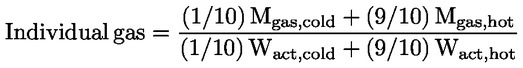
where
|
Mgas,cold
|
=
|
total mass of gaseous pollutant over the cold start cycle (g)
|
|
Mgas,hot
|
=
|
total mass of gaseous pollutant over the hot start cycle (g)
|
|
Wact,cold
|
=
|
actual cycle work over the cold start cycle as determined in section 4.6.2. of Annex III (kWh)
|
|
Wact,hot
|
=
|
actual cycle work over the hot start cycle as determined in section 4.6.2. of Annex III. (kWh)
|
▼C1
2.2.5. Calculation of the particulate emission
▼M6
2.2.5.1.
Calculation of the mass flow
The particulate masses MPT,cold and MPT,hot (g/test) shall be calculated as follows:
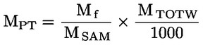
where
|
MPT
|
=
|
MPT,cold for the cold start cycle
|
|
MPT
|
=
|
MPT,hot for the hot start cycle
|
|
Mf
|
=
|
particulate mass sampled over the cycle (mg)
|
|
MTOTW
|
=
|
total mass of diluted exhaust gas over the cycle as determined in section 2.2.1. (kg)
|
|
MSAM
|
=
|
mass of diluted exhaust gas taken from the dilution tunnel for collecting particulates (kg)
|
and,
|
Mf
|
=
|
Mf,p + Mf,b, if weighed separately (mg)
|
|
Mf,p
|
=
|
particulate mass collected on the primary filter (mg)
|
|
Mf,b
|
=
|
particulate mass collected on the back-up filter (mg)
|
If a double dilution system is used, the mass of the secondary dilution air shall be subtracted from the total mass of the double diluted exhaust gas sampled through the particulate filters.
MSAM = MTOT – MSEC
where,
|
MTOT
|
=
|
mass of double diluted exhaust gas through particulate filter (kg)
|
|
MSEC
|
=
|
mass of secondary dilution air (kg)
|
If the particulate background level of the dilution air is determined in accordance with section 4.4.4 of Annex III, the particulate mass may be background corrected. In this case, the particulate masses MPT,cold and MPT,hot (g/test) shall be calculated as follows:
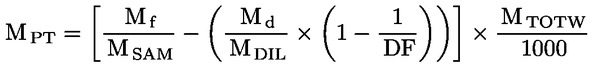
where
|
MPT
|
=
|
MPT,cold for the cold start cycle
|
|
MPT
|
=
|
MPT,hot for the hot start cycle
|
|
Mf, MSAM, MTOTW
|
=
|
see above
|
|
MDIL
|
=
|
mass of primary dilution air sampled by background particulate sampler (kg)
|
|
Md
|
=
|
mass of the collected background particulates of the primary dilution air (mg)
|
|
DF
|
=
|
dilution factor as determined in section 2.2.3.1.1
|
▼C1
2.2.5.2. Particulate correction factor for humidity
As the particulate emission of diesel engines depends on ambient air conditions, the particulate concentration shall be corrected for ambient air humidity with the factor Kp given in the following formula.
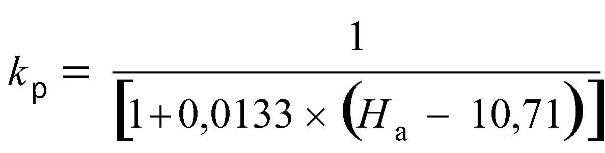
where
|
Ha
|
=
|
humidity of the intake air in g water per kg dry air
|
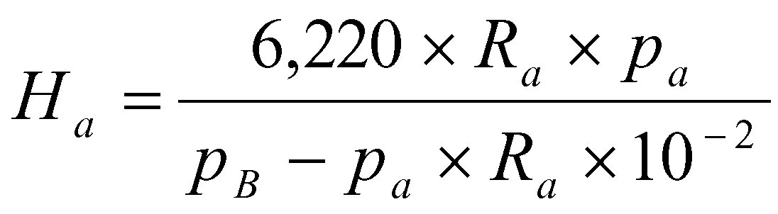
where:
|
Ra
|
:
|
relative humidity of the intake air ( %)
|
|
pa
|
:
|
saturation vapour pressure of the intake air (kPa)
|
|
pB
|
:
|
total barometric pressure (kPa)
|
Note:
H
a may be derived from relative humidity measurement, as described above, or from dewpoint measurement, vapour pressure measurement or dry/wet bulb measurement using the generally accepted formulae.
▼M6
2.2.5.3.
Calculation of the specific emissions
The specific emissions (g/kWh) shall be calculated for in the following way:

where
|
MPT,cold
|
=
|
particulate mass over the cold start cycle of NRTC, (g/test)
|
|
MPT,hot
|
=
|
particulate mass over the hot start cycle of NRTC, (g/test)
|
|
Kp, cold
|
=
|
humidity correction factor for particulate over the cold start cycle
|
|
Kp, hot
|
=
|
humidity correction factor for particulate over the hot start cycle
|
|
Wact, cold
|
=
|
actual cycle work over the cold start cycle as determined in section 4.6.2. of Annex III, (kWh)
|
|
Wact, hot
|
=
|
actual cycle work over the hot start cycle as determined in section 4.6.2 of Annex III, (kWh)
|
▼M3
Appendix 4
NRTC ENGINE DYNAMOMETER SCHEDULE
|
Time
(s)
|
Norm. Speed
(%)
|
Norm. Torque
(%)
|
|
1
|
0
|
0
|
|
2
|
0
|
0
|
|
3
|
0
|
0
|
|
4
|
0
|
0
|
|
5
|
0
|
0
|
|
6
|
0
|
0
|
|
7
|
0
|
0
|
|
8
|
0
|
0
|
|
9
|
0
|
0
|
|
10
|
0
|
0
|
|
11
|
0
|
0
|
|
12
|
0
|
0
|
|
13
|
0
|
0
|
|
14
|
0
|
0
|
|
15
|
0
|
0
|
|
16
|
0
|
0
|
|
17
|
0
|
0
|
|
18
|
0
|
0
|
|
19
|
0
|
0
|
|
20
|
0
|
0
|
|
21
|
0
|
0
|
|
22
|
0
|
0
|
|
23
|
0
|
0
|
|
24
|
1
|
3
|
|
25
|
1
|
3
|
|
26
|
1
|
3
|
|
27
|
1
|
3
|
|
28
|
1
|
3
|
|
29
|
1
|
3
|
|
30
|
1
|
6
|
|
31
|
1
|
6
|
|
32
|
2
|
1
|
|
33
|
4
|
13
|
|
34
|
7
|
18
|
|
35
|
9
|
21
|
|
36
|
17
|
20
|
|
37
|
33
|
42
|
|
38
|
57
|
46
|
|
39
|
44
|
33
|
|
40
|
31
|
0
|
|
41
|
22
|
27
|
|
42
|
33
|
43
|
|
43
|
80
|
49
|
|
44
|
105
|
47
|
|
45
|
98
|
70
|
|
46
|
104
|
36
|
|
47
|
104
|
65
|
|
48
|
96
|
71
|
|
49
|
101
|
62
|
|
50
|
102
|
51
|
|
51
|
102
|
50
|
|
52
|
102
|
46
|
|
53
|
102
|
41
|
|
54
|
102
|
31
|
|
55
|
89
|
2
|
|
56
|
82
|
0
|
|
57
|
47
|
1
|
|
58
|
23
|
1
|
|
59
|
1
|
3
|
|
60
|
1
|
8
|
|
61
|
1
|
3
|
|
62
|
1
|
5
|
|
63
|
1
|
6
|
|
64
|
1
|
4
|
|
65
|
1
|
4
|
|
66
|
0
|
6
|
|
67
|
1
|
4
|
|
68
|
9
|
21
|
|
69
|
25
|
56
|
|
70
|
64
|
26
|
|
71
|
60
|
31
|
|
72
|
63
|
20
|
|
73
|
62
|
24
|
|
74
|
64
|
8
|
|
75
|
58
|
44
|
|
76
|
65
|
10
|
|
77
|
65
|
12
|
|
78
|
68
|
23
|
|
79
|
69
|
30
|
|
80
|
71
|
30
|
|
81
|
74
|
15
|
|
82
|
71
|
23
|
|
83
|
73
|
20
|
|
84
|
73
|
21
|
|
85
|
73
|
19
|
|
86
|
70
|
33
|
|
87
|
70
|
34
|
|
88
|
65
|
47
|
|
89
|
66
|
47
|
|
90
|
64
|
53
|
|
91
|
65
|
45
|
|
92
|
66
|
38
|
|
93
|
67
|
49
|
|
94
|
69
|
39
|
|
95
|
69
|
39
|
|
96
|
66
|
42
|
|
97
|
71
|
29
|
|
98
|
75
|
29
|
|
99
|
72
|
23
|
|
100
|
74
|
22
|
|
101
|
75
|
24
|
|
102
|
73
|
30
|
|
103
|
74
|
24
|
|
104
|
77
|
6
|
|
105
|
76
|
12
|
|
106
|
74
|
39
|
|
107
|
72
|
30
|
|
108
|
75
|
22
|
|
109
|
78
|
64
|
|
110
|
102
|
34
|
|
111
|
103
|
28
|
|
112
|
103
|
28
|
|
113
|
103
|
19
|
|
114
|
103
|
32
|
|
115
|
104
|
25
|
|
116
|
103
|
38
|
|
117
|
103
|
39
|
|
118
|
103
|
34
|
|
119
|
102
|
44
|
|
120
|
103
|
38
|
|
121
|
102
|
43
|
|
122
|
103
|
34
|
|
123
|
102
|
41
|
|
124
|
103
|
44
|
|
125
|
103
|
37
|
|
126
|
103
|
27
|
|
127
|
104
|
13
|
|
128
|
104
|
30
|
|
129
|
104
|
19
|
|
130
|
103
|
28
|
|
131
|
104
|
40
|
|
132
|
104
|
32
|
|
133
|
101
|
63
|
|
134
|
102
|
54
|
|
135
|
102
|
52
|
|
136
|
102
|
51
|
|
137
|
103
|
40
|
|
138
|
104
|
34
|
|
139
|
102
|
36
|
|
140
|
104
|
44
|
|
141
|
103
|
44
|
|
142
|
104
|
33
|
|
143
|
102
|
27
|
|
144
|
103
|
26
|
|
145
|
79
|
53
|
|
146
|
51
|
37
|
|
147
|
24
|
23
|
|
148
|
13
|
33
|
|
149
|
19
|
55
|
|
150
|
45
|
30
|
|
151
|
34
|
7
|
|
152
|
14
|
4
|
|
153
|
8
|
16
|
|
154
|
15
|
6
|
|
155
|
39
|
47
|
|
156
|
39
|
4
|
|
157
|
35
|
26
|
|
158
|
27
|
38
|
|
159
|
43
|
40
|
|
160
|
14
|
23
|
|
161
|
10
|
10
|
|
162
|
15
|
33
|
|
163
|
35
|
72
|
|
164
|
60
|
39
|
|
165
|
55
|
31
|
|
166
|
47
|
30
|
|
167
|
16
|
7
|
|
168
|
0
|
6
|
|
169
|
0
|
8
|
|
170
|
0
|
8
|
|
171
|
0
|
2
|
|
172
|
2
|
17
|
|
173
|
10
|
28
|
|
174
|
28
|
31
|
|
175
|
33
|
30
|
|
176
|
36
|
0
|
|
177
|
19
|
10
|
|
178
|
1
|
18
|
|
179
|
0
|
16
|
|
180
|
1
|
3
|
|
181
|
1
|
4
|
|
182
|
1
|
5
|
|
183
|
1
|
6
|
|
184
|
1
|
5
|
|
185
|
1
|
3
|
|
186
|
1
|
4
|
|
187
|
1
|
4
|
|
188
|
1
|
6
|
|
189
|
8
|
18
|
|
190
|
20
|
51
|
|
191
|
49
|
19
|
|
192
|
41
|
13
|
|
193
|
31
|
16
|
|
194
|
28
|
21
|
|
195
|
21
|
17
|
|
196
|
31
|
21
|
|
197
|
21
|
8
|
|
198
|
0
|
14
|
|
199
|
0
|
12
|
|
200
|
3
|
8
|
|
201
|
3
|
22
|
|
202
|
12
|
20
|
|
203
|
14
|
20
|
|
204
|
16
|
17
|
|
205
|
20
|
18
|
|
206
|
27
|
34
|
|
207
|
32
|
33
|
|
208
|
41
|
31
|
|
209
|
43
|
31
|
|
210
|
37
|
33
|
|
211
|
26
|
18
|
|
212
|
18
|
29
|
|
213
|
14
|
51
|
|
214
|
13
|
11
|
|
215
|
12
|
9
|
|
216
|
15
|
33
|
|
217
|
20
|
25
|
|
218
|
25
|
17
|
|
219
|
31
|
29
|
|
220
|
36
|
66
|
|
221
|
66
|
40
|
|
222
|
50
|
13
|
|
223
|
16
|
24
|
|
224
|
26
|
50
|
|
225
|
64
|
23
|
|
226
|
81
|
20
|
|
227
|
83
|
11
|
|
228
|
79
|
23
|
|
229
|
76
|
31
|
|
230
|
68
|
24
|
|
231
|
59
|
33
|
|
232
|
59
|
3
|
|
233
|
25
|
7
|
|
234
|
21
|
10
|
|
235
|
20
|
19
|
|
236
|
4
|
10
|
|
237
|
5
|
7
|
|
238
|
4
|
5
|
|
239
|
4
|
6
|
|
240
|
4
|
6
|
|
241
|
4
|
5
|
|
242
|
7
|
5
|
|
243
|
16
|
28
|
|
244
|
28
|
25
|
|
245
|
52
|
53
|
|
246
|
50
|
8
|
|
247
|
26
|
40
|
|
248
|
48
|
29
|
|
249
|
54
|
39
|
|
250
|
60
|
42
|
|
251
|
48
|
18
|
|
252
|
54
|
51
|
|
253
|
88
|
90
|
|
254
|
103
|
84
|
|
255
|
103
|
85
|
|
256
|
102
|
84
|
|
257
|
58
|
66
|
|
258
|
64
|
97
|
|
259
|
56
|
80
|
|
260
|
51
|
67
|
|
261
|
52
|
96
|
|
262
|
63
|
62
|
|
263
|
71
|
6
|
|
264
|
33
|
16
|
|
265
|
47
|
45
|
|
266
|
43
|
56
|
|
267
|
42
|
27
|
|
268
|
42
|
64
|
|
269
|
75
|
74
|
|
270
|
68
|
96
|
|
271
|
86
|
61
|
|
272
|
66
|
0
|
|
273
|
37
|
0
|
|
274
|
45
|
37
|
|
275
|
68
|
96
|
|
276
|
80
|
97
|
|
277
|
92
|
96
|
|
278
|
90
|
97
|
|
279
|
82
|
96
|
|
280
|
94
|
81
|
|
281
|
90
|
85
|
|
282
|
96
|
65
|
|
283
|
70
|
96
|
|
284
|
55
|
95
|
|
285
|
70
|
96
|
|
286
|
79
|
96
|
|
287
|
81
|
71
|
|
288
|
71
|
60
|
|
289
|
92
|
65
|
|
290
|
82
|
63
|
|
291
|
61
|
47
|
|
292
|
52
|
37
|
|
293
|
24
|
0
|
|
294
|
20
|
7
|
|
295
|
39
|
48
|
|
296
|
39
|
54
|
|
297
|
63
|
58
|
|
298
|
53
|
31
|
|
299
|
51
|
24
|
|
300
|
48
|
40
|
|
301
|
39
|
0
|
|
302
|
35
|
18
|
|
303
|
36
|
16
|
|
304
|
29
|
17
|
|
305
|
28
|
21
|
|
306
|
31
|
15
|
|
307
|
31
|
10
|
|
308
|
43
|
19
|
|
309
|
49
|
63
|
|
310
|
78
|
61
|
|
311
|
78
|
46
|
|
312
|
66
|
65
|
|
313
|
78
|
97
|
|
314
|
84
|
63
|
|
315
|
57
|
26
|
|
316
|
36
|
22
|
|
317
|
20
|
34
|
|
318
|
19
|
8
|
|
319
|
9
|
10
|
|
320
|
5
|
5
|
|
321
|
7
|
11
|
|
322
|
15
|
15
|
|
323
|
12
|
9
|
|
324
|
13
|
27
|
|
325
|
15
|
28
|
|
326
|
16
|
28
|
|
327
|
16
|
31
|
|
328
|
15
|
20
|
|
329
|
17
|
0
|
|
330
|
20
|
34
|
|
331
|
21
|
25
|
|
332
|
20
|
0
|
|
333
|
23
|
25
|
|
334
|
30
|
58
|
|
335
|
63
|
96
|
|
336
|
83
|
60
|
|
337
|
61
|
0
|
|
338
|
26
|
0
|
|
339
|
29
|
44
|
|
340
|
68
|
97
|
|
341
|
80
|
97
|
|
342
|
88
|
97
|
|
343
|
99
|
88
|
|
344
|
102
|
86
|
|
345
|
100
|
82
|
|
346
|
74
|
79
|
|
347
|
57
|
79
|
|
348
|
76
|
97
|
|
349
|
84
|
97
|
|
350
|
86
|
97
|
|
351
|
81
|
98
|
|
352
|
83
|
83
|
|
353
|
65
|
96
|
|
354
|
93
|
72
|
|
355
|
63
|
60
|
|
356
|
72
|
49
|
|
357
|
56
|
27
|
|
358
|
29
|
0
|
|
359
|
18
|
13
|
|
360
|
25
|
11
|
|
361
|
28
|
24
|
|
362
|
34
|
53
|
|
363
|
65
|
83
|
|
364
|
80
|
44
|
|
365
|
77
|
46
|
|
366
|
76
|
50
|
|
367
|
45
|
52
|
|
368
|
61
|
98
|
|
369
|
61
|
69
|
|
370
|
63
|
49
|
|
371
|
32
|
0
|
|
372
|
10
|
8
|
|
373
|
17
|
7
|
|
374
|
16
|
13
|
|
375
|
11
|
6
|
|
376
|
9
|
5
|
|
377
|
9
|
12
|
|
378
|
12
|
46
|
|
379
|
15
|
30
|
|
380
|
26
|
28
|
|
381
|
13
|
9
|
|
382
|
16
|
21
|
|
383
|
24
|
4
|
|
384
|
36
|
43
|
|
385
|
65
|
85
|
|
386
|
78
|
66
|
|
387
|
63
|
39
|
|
388
|
32
|
34
|
|
389
|
46
|
55
|
|
390
|
47
|
42
|
|
391
|
42
|
39
|
|
392
|
27
|
0
|
|
393
|
14
|
5
|
|
394
|
14
|
14
|
|
395
|
24
|
54
|
|
396
|
60
|
90
|
|
397
|
53
|
66
|
|
398
|
70
|
48
|
|
399
|
77
|
93
|
|
400
|
79
|
67
|
|
401
|
46
|
65
|
|
402
|
69
|
98
|
|
403
|
80
|
97
|
|
404
|
74
|
97
|
|
405
|
75
|
98
|
|
406
|
56
|
61
|
|
407
|
42
|
0
|
|
408
|
36
|
32
|
|
409
|
34
|
43
|
|
410
|
68
|
83
|
|
411
|
102
|
48
|
|
412
|
62
|
0
|
|
413
|
41
|
39
|
|
414
|
71
|
86
|
|
415
|
91
|
52
|
|
416
|
89
|
55
|
|
417
|
89
|
56
|
|
418
|
88
|
58
|
|
419
|
78
|
69
|
|
420
|
98
|
39
|
|
421
|
64
|
61
|
|
422
|
90
|
34
|
|
423
|
88
|
38
|
|
424
|
97
|
62
|
|
425
|
100
|
53
|
|
426
|
81
|
58
|
|
427
|
74
|
51
|
|
428
|
76
|
57
|
|
429
|
76
|
72
|
|
430
|
85
|
72
|
|
431
|
84
|
60
|
|
432
|
83
|
72
|
|
433
|
83
|
72
|
|
434
|
86
|
72
|
|
435
|
89
|
72
|
|
436
|
86
|
72
|
|
437
|
87
|
72
|
|
438
|
88
|
72
|
|
439
|
88
|
71
|
|
440
|
87
|
72
|
|
441
|
85
|
71
|
|
442
|
88
|
72
|
|
443
|
88
|
72
|
|
444
|
84
|
72
|
|
445
|
83
|
73
|
|
446
|
77
|
73
|
|
447
|
74
|
73
|
|
448
|
76
|
72
|
|
449
|
46
|
77
|
|
450
|
78
|
62
|
|
451
|
79
|
35
|
|
452
|
82
|
38
|
|
453
|
81
|
41
|
|
454
|
79
|
37
|
|
455
|
78
|
35
|
|
456
|
78
|
38
|
|
457
|
78
|
46
|
|
458
|
75
|
49
|
|
459
|
73
|
50
|
|
460
|
79
|
58
|
|
461
|
79
|
71
|
|
462
|
83
|
44
|
|
463
|
53
|
48
|
|
464
|
40
|
48
|
|
465
|
51
|
75
|
|
466
|
75
|
72
|
|
467
|
89
|
67
|
|
468
|
93
|
60
|
|
469
|
89
|
73
|
|
470
|
86
|
73
|
|
471
|
81
|
73
|
|
472
|
78
|
73
|
|
473
|
78
|
73
|
|
474
|
76
|
73
|
|
475
|
79
|
73
|
|
476
|
82
|
73
|
|
477
|
86
|
73
|
|
478
|
88
|
72
|
|
479
|
92
|
71
|
|
480
|
97
|
54
|
|
481
|
73
|
43
|
|
482
|
36
|
64
|
|
483
|
63
|
31
|
|
484
|
78
|
1
|
|
485
|
69
|
27
|
|
486
|
67
|
28
|
|
487
|
72
|
9
|
|
488
|
71
|
9
|
|
489
|
78
|
36
|
|
490
|
81
|
56
|
|
491
|
75
|
53
|
|
492
|
60
|
45
|
|
493
|
50
|
37
|
|
494
|
66
|
41
|
|
495
|
51
|
61
|
|
496
|
68
|
47
|
|
497
|
29
|
42
|
|
498
|
24
|
73
|
|
499
|
64
|
71
|
|
500
|
90
|
71
|
|
501
|
100
|
61
|
|
502
|
94
|
73
|
|
503
|
84
|
73
|
|
504
|
79
|
73
|
|
505
|
75
|
72
|
|
506
|
78
|
73
|
|
507
|
80
|
73
|
|
508
|
81
|
73
|
|
509
|
81
|
73
|
|
510
|
83
|
73
|
|
511
|
85
|
73
|
|
512
|
84
|
73
|
|
513
|
85
|
73
|
|
514
|
86
|
73
|
|
515
|
85
|
73
|
|
516
|
85
|
73
|
|
517
|
85
|
72
|
|
518
|
85
|
73
|
|
519
|
83
|
73
|
|
520
|
79
|
73
|
|
521
|
78
|
73
|
|
522
|
81
|
73
|
|
523
|
82
|
72
|
|
524
|
94
|
56
|
|
525
|
66
|
48
|
|
526
|
35
|
71
|
|
527
|
51
|
44
|
|
528
|
60
|
23
|
|
529
|
64
|
10
|
|
530
|
63
|
14
|
|
531
|
70
|
37
|
|
532
|
76
|
45
|
|
533
|
78
|
18
|
|
534
|
76
|
51
|
|
535
|
75
|
33
|
|
536
|
81
|
17
|
|
537
|
76
|
45
|
|
538
|
76
|
30
|
|
539
|
80
|
14
|
|
540
|
71
|
18
|
|
541
|
71
|
14
|
|
542
|
71
|
11
|
|
543
|
65
|
2
|
|
544
|
31
|
26
|
|
545
|
24
|
72
|
|
546
|
64
|
70
|
|
547
|
77
|
62
|
|
548
|
80
|
68
|
|
549
|
83
|
53
|
|
550
|
83
|
50
|
|
551
|
83
|
50
|
|
552
|
85
|
43
|
|
553
|
86
|
45
|
|
554
|
89
|
35
|
|
555
|
82
|
61
|
|
556
|
87
|
50
|
|
557
|
85
|
55
|
|
558
|
89
|
49
|
|
559
|
87
|
70
|
|
560
|
91
|
39
|
|
561
|
72
|
3
|
|
562
|
43
|
25
|
|
563
|
30
|
60
|
|
564
|
40
|
45
|
|
565
|
37
|
32
|
|
566
|
37
|
32
|
|
567
|
43
|
70
|
|
568
|
70
|
54
|
|
569
|
77
|
47
|
|
570
|
79
|
66
|
|
571
|
85
|
53
|
|
572
|
83
|
57
|
|
573
|
86
|
52
|
|
574
|
85
|
51
|
|
575
|
70
|
39
|
|
576
|
50
|
5
|
|
577
|
38
|
36
|
|
578
|
30
|
71
|
|
579
|
75
|
53
|
|
580
|
84
|
40
|
|
581
|
85
|
42
|
|
582
|
86
|
49
|
|
583
|
86
|
57
|
|
584
|
89
|
68
|
|
585
|
99
|
61
|
|
586
|
77
|
29
|
|
587
|
81
|
72
|
|
588
|
89
|
69
|
|
589
|
49
|
56
|
|
590
|
79
|
70
|
|
591
|
104
|
59
|
|
592
|
103
|
54
|
|
593
|
102
|
56
|
|
594
|
102
|
56
|
|
595
|
103
|
61
|
|
596
|
102
|
64
|
|
597
|
103
|
60
|
|
598
|
93
|
72
|
|
599
|
86
|
73
|
|
600
|
76
|
73
|
|
601
|
59
|
49
|
|
602
|
46
|
22
|
|
603
|
40
|
65
|
|
604
|
72
|
31
|
|
605
|
72
|
27
|
|
606
|
67
|
44
|
|
607
|
68
|
37
|
|
608
|
67
|
42
|
|
609
|
68
|
50
|
|
610
|
77
|
43
|
|
611
|
58
|
4
|
|
612
|
22
|
37
|
|
613
|
57
|
69
|
|
614
|
68
|
38
|
|
615
|
73
|
2
|
|
616
|
40
|
14
|
|
617
|
42
|
38
|
|
618
|
64
|
69
|
|
619
|
64
|
74
|
|
620
|
67
|
73
|
|
621
|
65
|
73
|
|
622
|
68
|
73
|
|
623
|
65
|
49
|
|
624
|
81
|
0
|
|
625
|
37
|
25
|
|
626
|
24
|
69
|
|
627
|
68
|
71
|
|
628
|
70
|
71
|
|
629
|
76
|
70
|
|
630
|
71
|
72
|
|
631
|
73
|
69
|
|
632
|
76
|
70
|
|
633
|
77
|
72
|
|
634
|
77
|
72
|
|
635
|
77
|
72
|
|
636
|
77
|
70
|
|
637
|
76
|
71
|
|
638
|
76
|
71
|
|
639
|
77
|
71
|
|
640
|
77
|
71
|
|
641
|
78
|
70
|
|
642
|
77
|
70
|
|
643
|
77
|
71
|
|
644
|
79
|
72
|
|
645
|
78
|
70
|
|
646
|
80
|
70
|
|
647
|
82
|
71
|
|
648
|
84
|
71
|
|
649
|
83
|
71
|
|
650
|
83
|
73
|
|
651
|
81
|
70
|
|
652
|
80
|
71
|
|
653
|
78
|
71
|
|
654
|
76
|
70
|
|
655
|
76
|
70
|
|
656
|
76
|
71
|
|
657
|
79
|
71
|
|
658
|
78
|
71
|
|
659
|
81
|
70
|
|
660
|
83
|
72
|
|
661
|
84
|
71
|
|
662
|
86
|
71
|
|
663
|
87
|
71
|
|
664
|
92
|
72
|
|
665
|
91
|
72
|
|
666
|
90
|
71
|
|
667
|
90
|
71
|
|
668
|
91
|
71
|
|
669
|
90
|
70
|
|
670
|
90
|
72
|
|
671
|
91
|
71
|
|
672
|
90
|
71
|
|
673
|
90
|
71
|
|
674
|
92
|
72
|
|
675
|
93
|
69
|
|
676
|
90
|
70
|
|
677
|
93
|
72
|
|
678
|
91
|
70
|
|
679
|
89
|
71
|
|
680
|
91
|
71
|
|
681
|
90
|
71
|
|
682
|
90
|
71
|
|
683
|
92
|
71
|
|
684
|
91
|
71
|
|
685
|
93
|
71
|
|
686
|
93
|
68
|
|
687
|
98
|
68
|
|
688
|
98
|
67
|
|
689
|
100
|
69
|
|
690
|
99
|
68
|
|
691
|
100
|
71
|
|
692
|
99
|
68
|
|
693
|
100
|
69
|
|
694
|
102
|
72
|
|
695
|
101
|
69
|
|
696
|
100
|
69
|
|
697
|
102
|
71
|
|
698
|
102
|
71
|
|
699
|
102
|
69
|
|
700
|
102
|
71
|
|
701
|
102
|
68
|
|
702
|
100
|
69
|
|
703
|
102
|
70
|
|
704
|
102
|
68
|
|
705
|
102
|
70
|
|
706
|
102
|
72
|
|
707
|
102
|
68
|
|
708
|
102
|
69
|
|
709
|
100
|
68
|
|
710
|
102
|
71
|
|
711
|
101
|
64
|
|
712
|
102
|
69
|
|
713
|
102
|
69
|
|
714
|
101
|
69
|
|
715
|
102
|
64
|
|
716
|
102
|
69
|
|
717
|
102
|
68
|
|
718
|
102
|
70
|
|
719
|
102
|
69
|
|
720
|
102
|
70
|
|
721
|
102
|
70
|
|
722
|
102
|
62
|
|
723
|
104
|
38
|
|
724
|
104
|
15
|
|
725
|
102
|
24
|
|
726
|
102
|
45
|
|
727
|
102
|
47
|
|
728
|
104
|
40
|
|
729
|
101
|
52
|
|
730
|
103
|
32
|
|
731
|
102
|
50
|
|
732
|
103
|
30
|
|
733
|
103
|
44
|
|
734
|
102
|
40
|
|
735
|
103
|
43
|
|
736
|
103
|
41
|
|
737
|
102
|
46
|
|
738
|
103
|
39
|
|
739
|
102
|
41
|
|
740
|
103
|
41
|
|
741
|
102
|
38
|
|
742
|
103
|
39
|
|
743
|
102
|
46
|
|
744
|
104
|
46
|
|
745
|
103
|
49
|
|
746
|
102
|
45
|
|
747
|
103
|
42
|
|
748
|
103
|
46
|
|
749
|
103
|
38
|
|
750
|
102
|
48
|
|
751
|
103
|
35
|
|
752
|
102
|
48
|
|
753
|
103
|
49
|
|
754
|
102
|
48
|
|
755
|
102
|
46
|
|
756
|
103
|
47
|
|
757
|
102
|
49
|
|
758
|
102
|
42
|
|
759
|
102
|
52
|
|
760
|
102
|
57
|
|
761
|
102
|
55
|
|
762
|
102
|
61
|
|
763
|
102
|
61
|
|
764
|
102
|
58
|
|
765
|
103
|
58
|
|
766
|
102
|
59
|
|
767
|
102
|
54
|
|
768
|
102
|
63
|
|
769
|
102
|
61
|
|
770
|
103
|
55
|
|
771
|
102
|
60
|
|
772
|
102
|
72
|
|
773
|
103
|
56
|
|
774
|
102
|
55
|
|
775
|
102
|
67
|
|
776
|
103
|
56
|
|
777
|
84
|
42
|
|
778
|
48
|
7
|
|
779
|
48
|
6
|
|
780
|
48
|
6
|
|
781
|
48
|
7
|
|
782
|
48
|
6
|
|
783
|
48
|
7
|
|
784
|
67
|
21
|
|
785
|
105
|
59
|
|
786
|
105
|
96
|
|
787
|
105
|
74
|
|
788
|
105
|
66
|
|
789
|
105
|
62
|
|
790
|
105
|
66
|
|
791
|
89
|
41
|
|
792
|
52
|
5
|
|
793
|
48
|
5
|
|
794
|
48
|
7
|
|
795
|
48
|
5
|
|
796
|
48
|
6
|
|
797
|
48
|
4
|
|
798
|
52
|
6
|
|
799
|
51
|
5
|
|
800
|
51
|
6
|
|
801
|
51
|
6
|
|
802
|
52
|
5
|
|
803
|
52
|
5
|
|
804
|
57
|
44
|
|
805
|
98
|
90
|
|
806
|
105
|
94
|
|
807
|
105
|
100
|
|
808
|
105
|
98
|
|
809
|
105
|
95
|
|
810
|
105
|
96
|
|
811
|
105
|
92
|
|
812
|
104
|
97
|
|
813
|
100
|
85
|
|
814
|
94
|
74
|
|
815
|
87
|
62
|
|
816
|
81
|
50
|
|
817
|
81
|
46
|
|
818
|
80
|
39
|
|
819
|
80
|
32
|
|
820
|
81
|
28
|
|
821
|
80
|
26
|
|
822
|
80
|
23
|
|
823
|
80
|
23
|
|
824
|
80
|
20
|
|
825
|
81
|
19
|
|
826
|
80
|
18
|
|
827
|
81
|
17
|
|
828
|
80
|
20
|
|
829
|
81
|
24
|
|
830
|
81
|
21
|
|
831
|
80
|
26
|
|
832
|
80
|
24
|
|
833
|
80
|
23
|
|
834
|
80
|
22
|
|
835
|
81
|
21
|
|
836
|
81
|
24
|
|
837
|
81
|
24
|
|
838
|
81
|
22
|
|
839
|
81
|
22
|
|
840
|
81
|
21
|
|
841
|
81
|
31
|
|
842
|
81
|
27
|
|
843
|
80
|
26
|
|
844
|
80
|
26
|
|
845
|
81
|
25
|
|
846
|
80
|
21
|
|
847
|
81
|
20
|
|
848
|
83
|
21
|
|
849
|
83
|
15
|
|
850
|
83
|
12
|
|
851
|
83
|
9
|
|
852
|
83
|
8
|
|
853
|
83
|
7
|
|
854
|
83
|
6
|
|
855
|
83
|
6
|
|
856
|
83
|
6
|
|
857
|
83
|
6
|
|
858
|
83
|
6
|
|
859
|
76
|
5
|
|
860
|
49
|
8
|
|
861
|
51
|
7
|
|
862
|
51
|
20
|
|
863
|
78
|
52
|
|
864
|
80
|
38
|
|
865
|
81
|
33
|
|
866
|
83
|
29
|
|
867
|
83
|
22
|
|
868
|
83
|
16
|
|
869
|
83
|
12
|
|
870
|
83
|
9
|
|
871
|
83
|
8
|
|
872
|
83
|
7
|
|
873
|
83
|
6
|
|
874
|
83
|
6
|
|
875
|
83
|
6
|
|
876
|
83
|
6
|
|
877
|
83
|
6
|
|
878
|
59
|
4
|
|
879
|
50
|
5
|
|
880
|
51
|
5
|
|
881
|
51
|
5
|
|
882
|
51
|
5
|
|
883
|
50
|
5
|
|
884
|
50
|
5
|
|
885
|
50
|
5
|
|
886
|
50
|
5
|
|
887
|
50
|
5
|
|
888
|
51
|
5
|
|
889
|
51
|
5
|
|
890
|
51
|
5
|
|
891
|
63
|
50
|
|
892
|
81
|
34
|
|
893
|
81
|
25
|
|
894
|
81
|
29
|
|
895
|
81
|
23
|
|
896
|
80
|
24
|
|
897
|
81
|
24
|
|
898
|
81
|
28
|
|
899
|
81
|
27
|
|
900
|
81
|
22
|
|
901
|
81
|
19
|
|
902
|
81
|
17
|
|
903
|
81
|
17
|
|
904
|
81
|
17
|
|
905
|
81
|
15
|
|
906
|
80
|
15
|
|
907
|
80
|
28
|
|
908
|
81
|
22
|
|
909
|
81
|
24
|
|
910
|
81
|
19
|
|
911
|
81
|
21
|
|
912
|
81
|
20
|
|
913
|
83
|
26
|
|
914
|
80
|
63
|
|
915
|
80
|
59
|
|
916
|
83
|
100
|
|
917
|
81
|
73
|
|
918
|
83
|
53
|
|
919
|
80
|
76
|
|
920
|
81
|
61
|
|
921
|
80
|
50
|
|
922
|
81
|
37
|
|
923
|
82
|
49
|
|
924
|
83
|
37
|
|
925
|
83
|
25
|
|
926
|
83
|
17
|
|
927
|
83
|
13
|
|
928
|
83
|
10
|
|
929
|
83
|
8
|
|
930
|
83
|
7
|
|
931
|
83
|
7
|
|
932
|
83
|
6
|
|
933
|
83
|
6
|
|
934
|
83
|
6
|
|
935
|
71
|
5
|
|
936
|
49
|
24
|
|
937
|
69
|
64
|
|
938
|
81
|
50
|
|
939
|
81
|
43
|
|
940
|
81
|
42
|
|
941
|
81
|
31
|
|
942
|
81
|
30
|
|
943
|
81
|
35
|
|
944
|
81
|
28
|
|
945
|
81
|
27
|
|
946
|
80
|
27
|
|
947
|
81
|
31
|
|
948
|
81
|
41
|
|
949
|
81
|
41
|
|
950
|
81
|
37
|
|
951
|
81
|
43
|
|
952
|
81
|
34
|
|
953
|
81
|
31
|
|
954
|
81
|
26
|
|
955
|
81
|
23
|
|
956
|
81
|
27
|
|
957
|
81
|
38
|
|
958
|
81
|
40
|
|
959
|
81
|
39
|
|
960
|
81
|
27
|
|
961
|
81
|
33
|
|
962
|
80
|
28
|
|
963
|
81
|
34
|
|
964
|
83
|
72
|
|
965
|
81
|
49
|
|
966
|
81
|
51
|
|
967
|
80
|
55
|
|
968
|
81
|
48
|
|
969
|
81
|
36
|
|
970
|
81
|
39
|
|
971
|
81
|
38
|
|
972
|
80
|
41
|
|
973
|
81
|
30
|
|
974
|
81
|
23
|
|
975
|
81
|
19
|
|
976
|
81
|
25
|
|
977
|
81
|
29
|
|
978
|
83
|
47
|
|
979
|
81
|
90
|
|
980
|
81
|
75
|
|
981
|
80
|
60
|
|
982
|
81
|
48
|
|
983
|
81
|
41
|
|
984
|
81
|
30
|
|
985
|
80
|
24
|
|
986
|
81
|
20
|
|
987
|
81
|
21
|
|
988
|
81
|
29
|
|
989
|
81
|
29
|
|
990
|
81
|
27
|
|
991
|
81
|
23
|
|
992
|
81
|
25
|
|
993
|
81
|
26
|
|
994
|
81
|
22
|
|
995
|
81
|
20
|
|
996
|
81
|
17
|
|
997
|
81
|
23
|
|
998
|
83
|
65
|
|
999
|
81
|
54
|
|
1 000
|
81
|
50
|
|
1 001
|
81
|
41
|
|
1 002
|
81
|
35
|
|
1 003
|
81
|
37
|
|
1 004
|
81
|
29
|
|
1 005
|
81
|
28
|
|
1 006
|
81
|
24
|
|
1 007
|
81
|
19
|
|
1 008
|
81
|
16
|
|
1 009
|
80
|
16
|
|
1 010
|
83
|
23
|
|
1 011
|
83
|
17
|
|
1 012
|
83
|
13
|
|
1 013
|
83
|
27
|
|
1 014
|
81
|
58
|
|
1 015
|
81
|
60
|
|
1 016
|
81
|
46
|
|
1 017
|
80
|
41
|
|
1 018
|
80
|
36
|
|
1 019
|
81
|
26
|
|
1 020
|
86
|
18
|
|
1 021
|
82
|
35
|
|
1 022
|
79
|
53
|
|
1 023
|
82
|
30
|
|
1 024
|
83
|
29
|
|
1 025
|
83
|
32
|
|
1 026
|
83
|
28
|
|
1 027
|
76
|
60
|
|
1 028
|
79
|
51
|
|
1 029
|
86
|
26
|
|
1 030
|
82
|
34
|
|
1 031
|
84
|
25
|
|
1 032
|
86
|
23
|
|
1 033
|
85
|
22
|
|
1 034
|
83
|
26
|
|
1 035
|
83
|
25
|
|
1 036
|
83
|
37
|
|
1 037
|
84
|
14
|
|
1 038
|
83
|
39
|
|
1 039
|
76
|
70
|
|
1 040
|
78
|
81
|
|
1 041
|
75
|
71
|
|
1 042
|
86
|
47
|
|
1 043
|
83
|
35
|
|
1 044
|
81
|
43
|
|
1 045
|
81
|
41
|
|
1 046
|
79
|
46
|
|
1 047
|
80
|
44
|
|
1 048
|
84
|
20
|
|
1 049
|
79
|
31
|
|
1 050
|
87
|
29
|
|
1 051
|
82
|
49
|
|
1 052
|
84
|
21
|
|
1 053
|
82
|
56
|
|
1 054
|
81
|
30
|
|
1 055
|
85
|
21
|
|
1 056
|
86
|
16
|
|
1 057
|
79
|
52
|
|
1 058
|
78
|
60
|
|
1 059
|
74
|
55
|
|
1 060
|
78
|
84
|
|
1 061
|
80
|
54
|
|
1 062
|
80
|
35
|
|
1 063
|
82
|
24
|
|
1 064
|
83
|
43
|
|
1 065
|
79
|
49
|
|
1 066
|
83
|
50
|
|
1 067
|
86
|
12
|
|
1 068
|
64
|
14
|
|
1 069
|
24
|
14
|
|
1 070
|
49
|
21
|
|
1 071
|
77
|
48
|
|
1 072
|
103
|
11
|
|
1 073
|
98
|
48
|
|
1 074
|
101
|
34
|
|
1 075
|
99
|
39
|
|
1 076
|
103
|
11
|
|
1 077
|
103
|
19
|
|
1 078
|
103
|
7
|
|
1 079
|
103
|
13
|
|
1 080
|
103
|
10
|
|
1 081
|
102
|
13
|
|
1 082
|
101
|
29
|
|
1 083
|
102
|
25
|
|
1 084
|
102
|
20
|
|
1 085
|
96
|
60
|
|
1 086
|
99
|
38
|
|
1 087
|
102
|
24
|
|
1 088
|
100
|
31
|
|
1 089
|
100
|
28
|
|
1 090
|
98
|
3
|
|
1 091
|
102
|
26
|
|
1 092
|
95
|
64
|
|
1 093
|
102
|
23
|
|
1 094
|
102
|
25
|
|
1 095
|
98
|
42
|
|
1 096
|
93
|
68
|
|
1 097
|
101
|
25
|
|
1 098
|
95
|
64
|
|
1 099
|
101
|
35
|
|
1 100
|
94
|
59
|
|
1 101
|
97
|
37
|
|
1 102
|
97
|
60
|
|
1 103
|
93
|
98
|
|
1 104
|
98
|
53
|
|
1 105
|
103
|
13
|
|
1 106
|
103
|
11
|
|
1 107
|
103
|
11
|
|
1 108
|
103
|
13
|
|
1 109
|
103
|
10
|
|
1 110
|
103
|
10
|
|
1 111
|
103
|
11
|
|
1 112
|
103
|
10
|
|
1 113
|
103
|
10
|
|
1 114
|
102
|
18
|
|
1 115
|
102
|
31
|
|
1 116
|
101
|
24
|
|
1 117
|
102
|
19
|
|
1 118
|
103
|
10
|
|
1 119
|
102
|
12
|
|
1 120
|
99
|
56
|
|
1 121
|
96
|
59
|
|
1 122
|
74
|
28
|
|
1 123
|
66
|
62
|
|
1 124
|
74
|
29
|
|
1 125
|
64
|
74
|
|
1 126
|
69
|
40
|
|
1 127
|
76
|
2
|
|
1 128
|
72
|
29
|
|
1 129
|
66
|
65
|
|
1 130
|
54
|
69
|
|
1 131
|
69
|
56
|
|
1 132
|
69
|
40
|
|
1 133
|
73
|
54
|
|
1 134
|
63
|
92
|
|
1 135
|
61
|
67
|
|
1 136
|
72
|
42
|
|
1 137
|
78
|
2
|
|
1 138
|
76
|
34
|
|
1 139
|
67
|
80
|
|
1 140
|
70
|
67
|
|
1 141
|
53
|
70
|
|
1 142
|
72
|
65
|
|
1 143
|
60
|
57
|
|
1 144
|
74
|
29
|
|
1 145
|
69
|
31
|
|
1 146
|
76
|
1
|
|
1 147
|
74
|
22
|
|
1 148
|
72
|
52
|
|
1 149
|
62
|
96
|
|
1 150
|
54
|
72
|
|
1 151
|
72
|
28
|
|
1 152
|
72
|
35
|
|
1 153
|
64
|
68
|
|
1 154
|
74
|
27
|
|
1 155
|
76
|
14
|
|
1 156
|
69
|
38
|
|
1 157
|
66
|
59
|
|
1 158
|
64
|
99
|
|
1 159
|
51
|
86
|
|
1 160
|
70
|
53
|
|
1 161
|
72
|
36
|
|
1 162
|
71
|
47
|
|
1 163
|
70
|
42
|
|
1 164
|
67
|
34
|
|
1 165
|
74
|
2
|
|
1 166
|
75
|
21
|
|
1 167
|
74
|
15
|
|
1 168
|
75
|
13
|
|
1 169
|
76
|
10
|
|
1 170
|
75
|
13
|
|
1 171
|
75
|
10
|
|
1 172
|
75
|
7
|
|
1 173
|
75
|
13
|
|
1 174
|
76
|
8
|
|
1 175
|
76
|
7
|
|
1 176
|
67
|
45
|
|
1 177
|
75
|
13
|
|
1 178
|
75
|
12
|
|
1 179
|
73
|
21
|
|
1 180
|
68
|
46
|
|
1 181
|
74
|
8
|
|
1 182
|
76
|
11
|
|
1 183
|
76
|
14
|
|
1 184
|
74
|
11
|
|
1 185
|
74
|
18
|
|
1 186
|
73
|
22
|
|
1 187
|
74
|
20
|
|
1 188
|
74
|
19
|
|
1 189
|
70
|
22
|
|
1 190
|
71
|
23
|
|
1 191
|
73
|
19
|
|
1 192
|
73
|
19
|
|
1 193
|
72
|
20
|
|
1 194
|
64
|
60
|
|
1 195
|
70
|
39
|
|
1 196
|
66
|
56
|
|
1 197
|
68
|
64
|
|
1 198
|
30
|
68
|
|
1 199
|
70
|
38
|
|
1 200
|
66
|
47
|
|
1 201
|
76
|
14
|
|
1 202
|
74
|
18
|
|
1 203
|
69
|
46
|
|
1 204
|
68
|
62
|
|
1 205
|
68
|
62
|
|
1 206
|
68
|
62
|
|
1 207
|
68
|
62
|
|
1 208
|
68
|
62
|
|
1 209
|
68
|
62
|
|
1 210
|
54
|
50
|
|
1 211
|
41
|
37
|
|
1 212
|
27
|
25
|
|
1 213
|
14
|
12
|
|
1 214
|
0
|
0
|
|
1 215
|
0
|
0
|
|
1 216
|
0
|
0
|
|
1 217
|
0
|
0
|
|
1 218
|
0
|
0
|
|
1 219
|
0
|
0
|
|
1 220
|
0
|
0
|
|
1 221
|
0
|
0
|
|
1 222
|
0
|
0
|
|
1 223
|
0
|
0
|
|
1 224
|
0
|
0
|
|
1 225
|
0
|
0
|
|
1 226
|
0
|
0
|
|
1 227
|
0
|
0
|
|
1 228
|
0
|
0
|
|
1 229
|
0
|
0
|
|
1 230
|
0
|
0
|
|
1 231
|
0
|
0
|
|
1 232
|
0
|
0
|
|
1 233
|
0
|
0
|
|
1 234
|
0
|
0
|
|
1 235
|
0
|
0
|
|
1 236
|
0
|
0
|
|
1 237
|
0
|
0
|
|
1 238
|
0
|
0
|
A graphical display of the NRTC dynamometer schedule is shown below


▼M8
Appendix 5
Durability requirements
1. VERIFYING THE DURABILITY OF STAGE IIIA AND STAGE IIIB CI ENGINES
This Appendix shall apply to CI engines Stage IIIA and IIIB only.
|
1.1.
|
Manufacturers shall determine a Deterioration Factor (DF) value for each regulated pollutant for all Stage IIIA and IIIB engine families. Such DFs shall be used for type approval and production line testing.
|
1.1.1.
|
Test to establish DFs shall be conducted as follows:
1.1.1.1. The manufacturer shall conduct durability tests to accumulate engine operating hours according to a test schedule that is selected on the basis of good engineering judgement to be representative of in-use engine operation in respect to characterising emission performance deterioration. The durability test period should typically represent the equivalent of at least one quarter of the emission durability period (EDP).
Service accumulation operating hours may be acquired through running engines on a dynamometer test bed or from actual infield machine operation. Accelerated durability tests can be applied whereby the service accumulation schedule is performed at a higher load factor than typically experienced in the field. The acceleration factor relating the number of engine durability test hours to the equivalent number of EDP hours shall be determined by the engine manufacturer based on good engineering judgement.
During the period of the durability test, no emission sensitive components can be serviced or replaced other than to the routine service schedule recommended by the manufacturer.
The test engine, subsystems, or components to be used to determine exhaust emission DFs for an engine family, or for engine families of equivalent emission control system technology, shall be selected by the engine manufacturer on the basis of good engineering judgement. The criterion is that the test engine should represent the emission deterioration characteristics of the engine families that will apply the resulting DF values for type approval. Engines of different bore and stroke, different configuration, different air management systems, different fuel systems can be considered as equivalent in respect to emissions deterioration characteristics if there is a reasonable technical basis for such determination.
DF values from another manufacturer can be applied if there is a reasonable basis for considering technology equivalence with respect to emissions deterioration, and evidence that the tests have been carried according to the specified requirements. Emissions testing shall be performed according to the procedures defined in this Directive for the test engine after initial run-in but before any service accumulation test, and at the completion of the durability test. Emission tests can also be performed at intervals during the service accumulation test period and applied in determining the deterioration trend.
1.1.1.2. The service accumulation tests or the emissions tests performed to determine deterioration need not be witnessed by the approval authority.
1.1.1.3. Determination of DF values from durability tests
An additive DF is defined as the value obtained by subtraction of the emission value determine at the beginning of the EDP from the emissions value determined to represent the emission performance at the end of the EDP.
A multiplicative DF is defined as the emission level determined for the end of the EDP divided by the emission value recorded at the beginning of the EDP.
Separate DF values shall be established for each of the pollutants covered by the legislation. In the case of establishing a DF value relative to the NOx + HC standard, for an additive DF, this is determined based on the sum of the pollutants notwithstanding that a negative deterioration for one pollutant may not offset deterioration for the other. For a multiplicative NOx + HC DF, separate HC and NOx DFs shall be determined and applied separately when calculating the deteriorated emission levels from an emissions test result before combining the resultant deteriorated NOx and HC values to establish compliance with the standard.
In cases where the testing is not conducted for the full EDP, the emission values at the end of the EDP is determined by extrapolation of the emission deterioration trend established for the test period, to the full EDP.
When emissions test results have been recorded periodically during the service accumulation durability testing, standard statistical processing techniques based on good practice shall be applied to determine the emission levels at the end of the EDP; statistical significance testing can be applied in the determination of the final emissions values.
If the calculation results in a value of less than 1,00 for a multiplicative DF, or less than 0,00 for an additive DF, then the DF shall be 1,0 or 0,00, respectively.
1.1.1.4. A manufacturer may, with the approval of the type approval authority, use DF values established from results of durability tests conducted to obtain DF values for certification of on-road HD CI engines. This will be allowed if there is technological equivalency between the test on-road engine and the non-road engine families applying the DF values for certification. The DF values, derived from on-road engine emission durability test results, must be calculated on the basis of EDP values defined in Section 3.
1.1.1.5. In the case where an engine family uses established technology, an analysis based on good engineering practices may be used in lieu of testing to determine a deterioration factor for that engine family subject to approval of the type approval authority.
|
|
|
1.2.
|
DF information in approval applications
|
1.2.1.
|
Additive DFs shall be specified for each pollutant in an engine family approval application for CI engines not using any after treatment device.
|
|
1.2.2.
|
Multiplicative DFs shall be specified for each pollutant in an engine family certification application for CI engines using an after treatment device.
|
|
1.2.3.
|
The manufacture shall furnish the type-approval authority on request with information to support the DF values. This would typically include emission test results, service accumulation schedule, maintenance procedures together with information to support engineering judgements of technological equivalency, if applicable.
|
|
2. VERIFYING THE DURABILITY OF STAGE IV CI ENGINES
2.1.
General
|
2.1.1.
|
This section shall apply to CI engines Stage IV. At the request of the manufacturer it may also be applied to CI engines stage IIIA and IIIB as an alternative to the requirements in Section 1 of this Appendix.
|
|
2.1.2.
|
This Section 2 details the procedures for selecting engines to be tested over a service accumulation schedule for the purpose of determining deterioration factors for stage IV engine type approval and conformity of production assessments. The deterioration factors shall be applied in accordance with paragraph 2.4.7 to the emissions measured according to Annex III to this Directive.
|
|
2.1.3.
|
The service accumulation tests or the emissions tests performed to determine deterioration need not be witnessed by the approval authority.
|
|
2.1.4.
|
This Section 2 also details the emission-related and non-emission-related maintenance that should be or may be carried out on engines undergoing a service accumulation schedule. Such maintenance shall conform to the maintenance performed on in-service engines and communicated to owners of new engines.
|
|
2.1.5.
|
At the request of the manufacturer, the type-approval authority may allow the use of deterioration factors that have been established using alternative procedures to those specified in Sections 2.4.1 to 2.4.5. In this case, the manufacturer must demonstrate to the satisfaction of the approval authority that the alternative procedures that have been used are no less rigorous than those contained in Sections 2.4.1 to 2.4.5.
|
2.2.
Definitions
Applicable for Section 2 of Appendix 5.
|
2.2.1.
|
‘Ageing cycle’ means the machine or engine operation (speed, load, power) to be executed during the service accumulation period.
|
|
2.2.2.
|
‘Critical emission-related components’ means the components which are designed primarily for emission control, that is, any exhaust after-treatment system, the electronic engine control unit and its associated sensors and actuators, and the EGR system including all related filters, coolers, control valves and tubing.
|
|
2.2.3.
|
‘Critical emission-related maintenance’ means the maintenance to be performed on critical emission-related components.
|
|
2.2.4.
|
‘Emission-related maintenance’ means the maintenance which substantially affects emissions or which is likely to affect emissions performance deterioration of the vehicle or the engine during normal in-use operation.
|
|
2.2.5.
|
‘Engine-after-treatment system family’ means a manufacturer’s grouping of engines that comply with the definition of engine family, but which are further grouped into a family of engine families utilising a similar exhaust after-treatment system.
|
|
2.2.6.
|
‘Non-emission-related maintenance’ means maintenance which does not substantially affect emissions and which does not have a lasting affect on the emissions performance deterioration of the machine or the engine during normal in-use operation once the maintenance is performed.
|
|
2.2.7.
|
‘Service accumulation schedule’ means the ageing cycle and the service accumulation period for determining the deterioration factors for the engine-after-treatment system family.
|
2.3.
Selection of engines for establishing emission durability period deterioration factors
|
2.3.1.
|
Engines shall be selected from the engine family defined in Section 6 of Annex I to this Directive for emission testing to establish emission durability period deterioration factors.
|
|
2.3.2.
|
Engines from different engine families may be further combined into families based on the type of exhaust after-treatment system utilised. In order to place engines with different cylinder configuration but having similar technical specifications and installation for the exhaust after-treatment systems into the same engine after-treatment system family, the manufacturer shall provide data to the approval authority that demonstrates that the emissions reduction performance of such engine systems is similar.
|
|
2.3.3.
|
One engine representing the engine-after-treatment system family, as determined in accordance with paragraph 2.3.2, shall be selected by the engine manufacturer for testing over the service accumulation schedule defined in paragraph 2.4.2, and shall be reported to the type-approval authority before any testing commences.
|
2.3.3.1.
|
If the type-approval authority decides that the worst case emissions of the engine-after-treatment system family can be characterised better by another engine then the test engine shall be selected jointly by the type-approval authority and the engine manufacturer.
|
|
2.4.
Establishing emission durability period deterioration factors
2.4.1.
General
Deterioration factors applicable to an engine-after-treatment system family are developed from the selected engines based on a service accumulation schedule that includes periodic testing for gaseous and particulate emissions over the NRSC and NRTC tests.
2.4.2.
Service accumulation schedule
Service accumulation schedules may be carried out at the choice of the manufacturer by running a machine equipped with the selected engine over an ‘in-service’ accumulation schedule or by running the selected engine over a ‘dynamometer service’ accumulation schedule.
2.4.2.1. In-service and dynamometer service accumulation
2.4.2.1.1. The manufacturer shall determine the form and duration of the service accumulation and the ageing cycle for engines in a manner consistent with good engineering practice.
2.4.2.1.2. The manufacturer shall determine the test points where gaseous and particulate emissions will be measured over the hot NRTC and NRSC cycles. The minimum number of test points shall be three, one at the beginning, one approximately in the middle and one at the end of the service accumulation schedule.
2.4.2.1.3. The emission values at the start point and at the emission durability period endpoint calculated in accordance with paragraph 2.4.5.2 shall be within the limit values applicable to the engine family, but individual emission results from the test points may exceed those limit values.
2.4.2.1.4. At the request of the manufacturer and with the agreement of the type-approval authority, only one test cycle (either the hot NRTC or NRSC cycle) needs to be run at each test point, with the other test cycle run only at the beginning and at the end of the service accumulation schedule.
2.4.2.1.5. In the case of constant speed engines, engines below 19 kW, engines above 560 kW, engines intended to be used in inland waterway vessels and engines for the propulsion of railcars and locomotives, only the NRSC cycle shall be run at each test point.
2.4.2.1.6. Service accumulation schedules may be different for different engine-after-treatment system families.
2.4.2.1.7. Service accumulation schedules may be shorter than the emission durability period, but shall not be shorter than the equivalent of at least one quarter of the relevant emission durability period specified in Section 3 of this Appendix.
2.4.2.1.8. Accelerated ageing by adjusting the service accumulation schedule on a fuel consumption basis is permitted. The adjustment shall be based on the ratio between the typical in-use fuel consumption and the fuel consumption on the ageing cycle, but fuel consumption on the ageing cycle must not exceed typical in-use fuel consumption by more than 30 %.
2.4.2.1.9. At the request of the manufacturer and with the agreement of the type-approval authority, alternative methods of accelerated ageing may be permitted.
2.4.2.1.10. The service accumulation schedule shall be fully described in the application for type-approval and reported to the type-approval authority before the start of any testing.
|
2.4.2.2.
|
If the type-approval authority decides that additional measurements need to be performed between the points selected by the manufacturer it shall notify the manufacturer. The revised service accumulation schedule shall be prepared by the manufacturer and agreed by the type-approval authority.
|
2.4.3.
Engine testing
2.4.3.1. Engine system stabilisation
2.4.3.1.1. For each engine-after-treatment system family, the manufacturer shall determine the number of hours of machine or engine running after which the operation of the engine-after-treatment system has stabilised. If requested by the approval authority the manufacturer shall make available the data and analysis used to make this determination. As an alternative, the manufacturer may select to run the engine or machine between 60 and 125 hours or the equivalent time on the ageing cycle to stabilise the engine-after-treatment system.
2.4.3.1.2. The end of the stabilisation period determined in Section 2.4.3.1.1 shall be deemed to be the start of the service accumulation schedule.
2.4.3.2. Service accumulation testing
2.4.3.2.1. After stabilisation, the engine shall be run over the service accumulation schedule selected by the manufacturer, as described in Section 2.3.2. At the periodic intervals in the service accumulation schedule determined by the manufacturer, and, where appropriate, also stipulated by the type-approval authority in accordance with Section 2.4.2.2, the engine shall be tested for gaseous and particulate emissions over the hot NRTC and NRSC cycles.
The manufacturer may select to measure the pollutant emissions before any exhaust after-treatment system separately from the pollutant emissions after any exhaust after-treatment system.
In accordance with Section 2.4.2.1.4, if it has been agreed that only one test cycle (hot NRTC or NRSC) be run at each test point, the other test cycle (hot NRTC or NRSC) shall be run at the beginning and end of the service accumulation schedule.
In accordance with Section 2.4.2.1.5, in the case of constant speed engines, engines below 19 kW, engines above 560 kW, engines intended to be used in inland waterway vessels and engines for the propulsion of railcars and locomotives, only the NRSC cycle shall be run at each test point.
2.4.3.2.2. During the service accumulation schedule, maintenance shall be carried out on the engine according to Section 2.5.
2.4.3.2.3. During the service accumulation schedule, unscheduled maintenance on the engine or machine may be performed, for example if the manufacturer’s normal diagnostic system has detected a problem that would have indicated to the machine operator that a fault had arisen.
2.4.4.
Reporting
|
2.4.4.1.
|
The results of all emission tests (hot NRTC and NRSC) conducted during the service accumulation schedule shall be made available to the type-approval authority. If any emission test is declared to be void, the manufacturer shall provide an explanation of why the test has been declared void. In such a case, another series of emission tests shall be carried out within the following 100 hours of service accumulation.
|
|
2.4.4.2.
|
The manufacturer shall retain records of all information concerning all the emission tests and maintenance carried out on the engine during the service accumulation schedule. This information shall be submitted to the approval authority along with the results of the emission tests conducted over the service accumulation schedule.
|
2.4.5.
Determination of deterioration factors
|
2.4.5.1.
|
For each pollutant measured over the hot NRTC and NRSC cycles at each test point during the service accumulation schedule, a ‘best fit’ linear regression analysis shall be made on the basis of all test results. The results of each test for each pollutant shall be expressed to the same number of decimal places as the limit value for that pollutant, as applicable to the engine family, plus one additional decimal place.
In accordance with Section 2.4.2.1.4 or Section 2.4.2.1.5, if only one test cycle (hot NRTC or NRSC) has been run at each test point, the regression analysis shall be made only on the basis of the test results from the test cycle run at each test point.
At the request of the manufacturer and with the prior approval of the type approval authority, non-linear regression is permitted.
|
|
2.4.5.2.
|
The emission values for each pollutant at the start of the service accumulation schedule and at the emission durability period end point that is applicable for the engine under test shall be calculated from the regression equation. If the service accumulation schedule is shorter than the emission durability period, the emission values at the emission durability period end point shall be determined by extrapolation of the regression equation as determined in Section 2.4.5.1.
In the case that emission values are used for engine families in the same engine-after-treatment family but with different emission durability periods, then the emission values at the emission durability period end point shall be recalculated for each emission durability period by extrapolation or interpolation of the regression equation as determined in Section 2.4.5.1.
|
|
2.4.5.3.
|
The deterioration factor (DF) for each pollutant is defined as the ratio of the applied emission values at the emission durability period end point and at the start of the service accumulation schedule (multiplicative deterioration factor).
At the request of the manufacturer and with the prior approval of the type-approval authority, an additive DF for each pollutant may be applied. The additive DF is defined as the difference between the calculated emission values at the emission durability period end point and at the start of the service accumulation schedule.
An example for determination of DFs by using linear regression is shown in Figure 1 for NOx emission.
Mixing of multiplicative and additive DFs within one set of pollutants is not permitted.
If the calculation results in a value of less than 1,00 for a multiplicative DF, or less than 0,00 for an additive DF, then the deterioration factor shall be 1,0 or 0,00, respectively.
In accordance with Section 2.4.2.1.4, if it has been agreed that only one test cycle (hot NRTC or NRSC) be run at each test point and the other test cycle (hot NRTC or NRSC) run only at the beginning and end of the service accumulation schedule, the deterioration factor calculated for the test cycle that has been run at each test point shall be applicable also for the other test cycle.

|
2.4.6.
Assigned deterioration factors
|
2.4.6.1.
|
As an alternative to using a service accumulation schedule to determine DFs, engine manufacturers may select to use the following assigned multiplicative DFs:
|
Test cycle
|
CO
|
HC
|
NOx
|
PM
|
|
NRTC
|
1,3
|
1,3
|
1,15
|
1,05
|
|
NRSC
|
1,3
|
1,3
|
1,15
|
1,05
|
Assigned additive DFs are not given. It is not permitted to transform the assigned multiplicative DFs into additive DFs.
Where assigned DFs are used, the manufacturer shall present to the type approval authority robust evidence that the emission control components can reasonably be expected to have the emission durability associated with those assigned factors. This evidence may be based upon design analysis, or tests, or a combination of both.
|
2.4.7.
Application of deterioration factors
|
2.4.7.1.
|
The engines shall meet the respective emission limits for each pollutant, as applicable to the engine family, after application of the deterioration factors to the test result as measured in accordance with Annex III (cycle-weighted specific emission for particulate and each individual gas). Depending on the type of DF, the following provisions apply:
— Multiplicative: (cycle weighted specific emission) * DF ≤ emission limit
— Additive: (cycle weighted specific emission) + DF ≤ emission limit
If the manufacturer, based on the option indicated in Section 1.2.1 of this Annex, chooses to use the procedure of Annex 4B to UNECE Regulation No 96.03 series of amendments, cycle weighted specific emission may include the adjustment for infrequent regeneration, where applicable.
|
|
2.4.7.2.
|
For a multiplicative NOx + HC DF, separate HC and NOx DFs shall be determined and applied separately when calculating the deteriorated emission levels from an emissions test result before combining the resultant deteriorated NOx and HC values to establish compliance with the emission limit.
|
|
2.4.7.3.
|
The manufacturer may select to carry across the DFs determined for an engine-after-treatment system family to an engine system that does not fall into the same engine-after-treatment system family. In such cases, the manufacturer shall demonstrate to the approval authority that the engine system for which the engine-after-treatment system family was originally tested and the engine system for which the DFs are being carried across have similar technical specifications and installation requirements on the machine and that the emissions of such engine or engine system are similar.
In the case that DFs are carried across to an engine system with a different emission durability period, then the DFs shall be recalculated for the applicable emission durability period by extrapolation or interpolation of the regression equation as determined in Section 2.4.5.1.
|
|
2.4.7.4.
|
The DF for each pollutant for each applicable test cycle shall be recorded in the test result document set out in Appendix 1 to Annex VII.
|
2.4.8.
Checking of conformity of production
|
2.4.8.1.
|
Conformity of production for emissions compliance is checked on the basis of Section 5 of Annex I.
|
|
2.4.8.2.
|
The manufacturer may select to measure the pollutant emissions before any exhaust after-treatment system at the same time as the type-approval test is being performed. In so doing, the manufacturer may develop informal DFs separately for the engine and for the after-treatment system that may be used by the manufacturer as an aid to end of production line auditing.
|
|
2.4.8.3.
|
For the purposes of type-approval, only the DFs determined in accordance with paragraph 2.4.5 or 2.4.6 shall be recorded in the test result document set out in Appendix 1 to Annex VII.
|
2.5.
Maintenance
For the purpose of the service accumulation schedule, maintenance shall be performed in accordance with the manufacturer’s manual for service and maintenance.
2.5.1.
Emission-related scheduled maintenance
|
2.5.1.1.
|
Emission-related scheduled maintenance during engine running, undertaken for the purpose of conducting a service accumulation schedule, must occur at equivalent intervals to those that will be specified in the manufacturer’s maintenance instructions to the owner of the machine or engine. This maintenance schedule may be updated as necessary throughout the service accumulation schedule provided that no maintenance operation is deleted from the maintenance schedule after the operation has been performed on the test engine.
|
|
2.5.1.2.
|
The engine manufacturer shall specify for the service accumulation schedules any adjustment, cleaning, maintenance (where necessary) and scheduled exchange of the following items:
— filters and coolers in the exhaust gas re-circulation system
— positive crankcase ventilation valve, if applicable
— fuel injector tips (only cleaning is permitted)
— electronic engine control unit and its associated sensors and actuators
— particulate after-treatment system (including related components)
— NOx after-treatment system (including related components)
— exhaust gas re-circulation system, including all related control valves and tubing
— any other exhaust after-treatment system.
|
|
2.5.1.3.
|
Critical emission-related scheduled maintenance shall only be performed if intended to be performed in-use and the requirement to perform such maintenance is to be communicated to the owner of the machine.
|
2.5.2.
Changes to scheduled maintenance
|
2.5.2.1.
|
The manufacturer shall submit a request to the type-approval authority for approval of any new scheduled maintenance that it wishes to perform during the service accumulation schedule and subsequently to recommend to owners of machines and engines. The request shall be accompanied by data supporting the need for the new scheduled maintenance and the maintenance interval.
|
2.5.3.
Non-emission-related scheduled maintenance
|
2.5.3.1.
|
Non-emission-related scheduled maintenance which is reasonable and technically necessary (for example oil change, oil filter change, fuel filter change, air filter change, cooling system maintenance, idle speed adjustment, governor, engine bolt torque, valve lash, injector lash, adjustment of the tension of any drive-belt, etc.) may be performed on engines or machines selected for the service accumulation schedule at the least frequent intervals recommended by the manufacturer to the owner (for example not at the intervals recommended for severe service).
|
2.5.4.
Repair
|
2.5.4.1.
|
Repairs to the components of an engine system selected for testing over a service accumulation schedule shall be performed only as a result of component failure or engine system malfunction. Repair of the engine itself, the emission control system or the fuel system is not permitted except to the extent defined in paragraph 2.5.4.2.
|
|
2.5.4.2.
|
If the engine itself, the emission control system or the fuel system fail during the service accumulation schedule, the service accumulation shall be considered void, and a new service accumulation shall be started with a new engine system, unless the failed components are replaced with equivalent components that have been subject to a similar number of hours of service accumulation.
|
3. EMISSION DURABILITY PERIOD FOR STAGE IIIA, IIIB AND IV ENGINES
|
3.1.
|
Manufacturers shall use the emission durability period in Table 1 of this section.
Table 1
Emission durability period for CI Stage IIIA, IIIB and IV Engines (hours)
|
Category (power band)
|
Emission durability period (hours)
|
|
≤ 37 kW
(constant speed engines)
|
3 000
|
|
≤ 37 kW
(variable speed engines)
|
5 000
|
|
> 37 kW
|
8 000
|
|
Engines for propulsion of inland waterway vessels
|
10 000
|
|
Railcar and Locomotive engines
|
10 000
|
|
▼M8
Appendix 6
Determination of CO2 Emissions for Stage I, II, IIIA, IIIB and IV Engines
1.
Introduction
|
1.1.
|
This Appendix sets out the provisions and test procedures for reporting CO2 emissions for all stages I through IV. If the manufacturer, based on the option indicated in Section 1.2.1 of this Annex, chooses to use the procedure of Annex 4B to UNECE Regulation No 96.03 series of amendments, Appendix 7 to this Annex shall apply.
|
2.
General requirements
|
2.1.
|
CO2 emissions shall be determined over the applicable test cycle specified in Section 1.1 of Annex III in accordance with Section 3 (NRSC) or Section 4 (hot start NRTC), respectively, of Annex III. For Stage IIIB CO2 emissions shall be determined over the hot start NRTC test cycle.
|
|
2.2.
|
The test results shall be reported as cycle averaged brake specific values and expressed in the unit of g/kWh.
|
|
2.3.
|
If, at the choice of the manufacturer, the NRSC is operated as a ramped modal cycle, either the references to the NRTC laid down in this Appendix or the requirements of Appendix 7 to Annex III shall apply.
|
3.
Determination of CO2 emissions
3.1.
Raw measurement
This section applies, if CO2 is measured in the raw exhaust gas.
3.1.1. Measurement
CO2 in the raw exhaust gas emitted by the engine submitted for testing shall be measured with a non-dispersive infrared (NDIR) analyser in accordance with Section 1.4.3.2 (NRSC) or Section 2.3.3.2 (NRTC), respectively, of Appendix 1 to Annex III.
The measurement system shall meet the linearity requirements of Section 1.5 of Appendix 2 to Annex III.
The measurement system shall meet the requirements of Section 1.4.1 (NRSC) or Section 2.3.1 (NRTC), respectively, of Appendix 1 to Annex III.
3.1.2. Data evaluation
The relevant data shall be recorded and stored in accordance with Section 3.7.4 (NRSC) or Section 4.5.7.2 (NRTC), respectively, of Annex III.
3.1.3. Calculation of cycle averaged emission
If measured on a dry basis, the dry/wet correction in accordance with Section 1.3.2 (NRSC) or Section 2.1.2.2 (NRTC), respectively, of Appendix 3 to Annex III shall be applied.
For the NRSC, the mass of CO2 (g/h) shall be calculated for each individual mode in accordance with Section 1.3.4 of Appendix 3 to Annex III. The exhaust gas flows shall be determined in accordance with Sections 1.2.1 to 1.2.5 of Appendix 1 to Annex III.
For the NRTC, the mass of CO2 (g/test) shall be calculated in accordance with Section 2.1.2.1 of Appendix 3 to Annex III. The exhaust gas flow shall be determined in accordance with Section 2.2.3 of Appendix 1 to Annex III.
3.2.
Dilute measurement
This section applies, if CO2 is measured in the dilute exhaust gas.
3.2.1. Measurement
CO2 in the dilute exhaust gas emitted by the engine submitted for testing shall be measured with a non-dispersive infrared (NDIR) analyser in accordance with Section 1.4.3.2 (NRSC) or Section 2.3.3.2 (NRTC), respectively, of Appendix 1 to Annex III. Dilution of the exhaust shall be done with filtered ambient air, synthetic air or nitrogen. The flow capacity of the full flow system shall be large enough to completely eliminate water condensation in the dilution and sampling systems.
The measurement system shall meet the linearity requirements of Section 1.5 of Appendix 2 to Annex III.
The measurement system shall meet the requirements of Section 1.4.1 (NRSC) or Section 2.3.1 (NRTC), respectively, of Appendix 1 to Annex III.
3.2.2. Data evaluation
The relevant data shall be recorded and stored in accordance with Section 3.7.4 (NRSC) or Section 4.5.7.2 (NRTC), respectively, of Annex III.
3.2.3. Calculation of cycle averaged emission
If measured on a dry basis, the dry/wet correction in accordance with Section 1.3.2 (NRSC) or Section 2.1.2.2 (NRTC), respectively, of Appendix 3 to Annex III shall be applied.
For the NRSC, the mass of CO2 (g/h) shall be calculated for each individual mode in accordance with Section 1.3.4 of Appendix 3 to Annex III. The diluted exhaust gas flows shall be determined in accordance with Section 1.2.6 of Appendix 1 to Annex III.
For the NRTC, the mass of CO2 (g/test) shall be calculated in accordance with Section 2.2.3 of Appendix 3 to Annex III. The diluted exhaust gas flow shall be determined in accordance with Section 2.2.1 of Appendix 3 to Annex III.
Background correction shall be applied in accordance with Section 2.2.3.1.1 of Appendix 3 to Annex III.
3.3.
Calculation of brake specific emissions
3.3.1. NRSC
The brake specific emissions e
CO2 (g/kWh) shall be calculated as follows:

where:

and
|
CO2 mass,i
|
is the mass of CO2 of the individual mode (g/h)
|
|
Pm,i
|
is the measured power of the individual mode (kW)
|
|
PAE,i
|
is the power of the auxiliaries of the individual mode (kW)
|
|
WF,i
|
is the weighting factor of the individual mode.
|
3.3.2. NRTC
The cycle work needed for the calculation of brake specific CO2 emissions shall be determined in accordance with Section 4.6.2 of Annex III.
The brake specific emissions e
CO2 (g/kWh) shall be calculated as follows:

where:
|
m
CO2, hot
|
is the CO2 mass emissions of the hot start NRTC (g)
|
|
W
act, hot
|
is the actual cycle work of the hot start NRTC (kWh).
|
Appendix 7
Alternative determination of CO2 emissions
1.
Introduction
If the manufacturer, based on the option indicated in Section 1.2.1 of this Annex, chooses to use the procedure of Annex 4B to UNECE Regulation No 96.03 series of amendments, the provisions and test procedures for reporting CO2 emissions set out in this Appendix shall apply.
2.
General requirements
|
2.1.
|
CO2 emissions shall be determined over the hot start NRTC test cycle in accordance with Section 7.8.3 of Annex 4B to UNECE Regulation No 96.03 series of amendments.
|
|
2.2.
|
The test results shall be reported as cycle averaged brake specific values and expressed in the unit of g/kWh.
|
3.
Determination of CO2 emissions
3.1.
Raw measurement
This section applies, if CO2 is measured in the raw exhaust gas.
3.1.1. Measurement
CO2 in the raw exhaust gas emitted by the engine submitted for testing shall be measured with a non-dispersive infrared (NDIR) analyser in accordance with Section 9.4.6 of Annex 4B to UNECE Regulation No 96.03 series of amendments.
The measurement system shall meet the linearity requirements of Section 8.1.4 of Annex 4B to UNECE Regulation No 96.03 series of amendments.
The measurement system shall meet the requirements of Section 8.1.9 of Annex 4B to UNECE Regulation No 96.03 series of amendments.
3.1.2. Data evaluation
The relevant data shall be recorded and stored in accordance with Section 7.8.3.2 of Annex 4B to UNECE Regulation No 96.03 series of amendments.
3.1.3. Calculation of cycle averaged emission
If measured on a dry basis, the dry/wet correction in accordance with Section A.8.2.2 of Appendix 8 or Section A.7.3.2 of Appendix 7 to Annex 4B to UNECE Regulation No 96.03 series of amendments shall be applied to the instantaneous concentration values before any further calculation is done.
The mass of CO2 (g/test) shall be calculated by multiplication of the time aligned instantaneous CO2 concentrations and exhaust gas flows and integration over the test cycle in accordance with either of the following:
(a) Section A.8.2.1.2 and Section A.8.2.5 of Appendix 8 to Annex 4B to UNECE Regulation No 96.03 series of amendments, by using the u values of CO2 from Table A.8.1 or calculating the u values in accordance with Section A.8.2.4.2 of Appendix 8 to Annex 4B to UNECE Regulation No 96.03 series of amendments;
(b) Section A.7.3.1 and Section A.7.3.3 of Appendix 7 to Annex 4B to UNECE Regulation No 96.03 series of amendments.
3.2.
Dilute measurement
This section applies, if CO2 is measured in the dilute exhaust gas.
3.2.1. Measurement
CO2 in the dilute exhaust gas emitted by the engine submitted for testing shall be measured with a non-dispersive infrared (NDIR) analyser in accordance with Section 9.4.6 of Annex 4B to UNECE Regulation No 96.03 series of amendments. Dilution of the exhaust shall be done with filtered ambient air, synthetic air or nitrogen. The flow capacity of the full flow system shall be large enough to completely eliminate water condensation in the dilution and sampling systems.
The measurement system shall meet the linearity requirements of Section 8.1.4 of Annex 4B to UNECE Regulation No 96.03 series of amendments.
The measurement system shall meet the requirements of Section 8.1.9 of Annex 4B to UNECE Regulation No 96.03 series of amendments.
3.2.2. Data evaluation
The relevant data shall be recorded and stored in accordance with Section 7.8.3.2 of Annex 4B to UNECE Regulation No 96.03 series of amendments.
3.2.3. Calculation of cycle averaged emission
If measured on a dry basis, the dry/wet correction in accordance with Section A.8.3.2 of Appendix 8 or Section A.7.4.2 of Appendix 7 to Annex 4B to UNECE Regulation No 96.03 series of amendments shall be applied to the instantaneous concentration values before any further calculation is done.
The mass of CO2 (g/test) shall be calculated by multiplication of the CO2 concentrations and the diluted exhaust gas flows in accordance with either of the following:
(a) Section A.8.3.1 and Section A.8.3.4 of Appendix 8 to Annex 4B to UNECE Regulation No 96.03 series of amendments, by using the u values of CO2 from Table A.8.2 or calculating the u values in accordance with Section A.8.3.3 of Appendix 8 to Annex 4B to UNECE Regulation No 96.03 series of amendments;
(b) Section A.7.4.1 and Section A.7.4.3 of Appendix 7 to Annex 4B to UNECE Regulation No 96.03 series of amendments.
Background correction shall be applied in accordance with Section A.8.3.2.4 of Appendix 8 or Section A.7.4.1 of Appendix 8 to Annex 4B to UNECE Regulation No 96.03 series of amendments.
3.3.
Calculation of brake specific emissions
The cycle work needed for the calculation of brake specific CO2 emissions shall be determined in accordance with Section 7.8.3.4 of Annex 4B to UNECE Regulation No 96.03 series of amendments.
The brake specific emissions eCO2 (g/kWh) shall be calculated as follows:
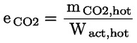
where:
|
mCO2, hot
|
is the CO2 mass emissions of the hot start NRTC (g)
|
|
Wact, hot
|
is the actual cycle work of the hot start NRTC (kWh)
|
▼M2
ANNEX IV
TEST PROCEDURE FOR SPARK IGNITION ENGINES
1. INTRODUCTION
|
1.1.
|
This Annex describes the method of determining emissions of gaseous pollutants from the engines to be tested.
|
|
1.2.
|
The test shall be carried out with the engine mounted on a test bench and connected to a dynamometer.
|
2. TEST CONDITIONS
2.1. Engine test conditions
The absolute temperature (Ta) of the engine air at the inlet to the engine, expressed in Kelvin, and the dry atmospheric pressure (ps), expressed in kPa, shall be measured and the parameter f
a shall be determined according to the following provisions:

2.1.1. Test validity
For a test to be recognised as valid, the parameter f
a shall be such that:
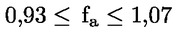
2.1.2. Engines with charge air-cooling
The temperature of the cooling medium and the temperature of the charge air have to be recorded.
2.2. Engine air inlet system
The test engine shall be equipped with an air inlet system presenting an air inlet restriction within 10 % of the upper limit specified by the manufacturer for a new air cleaner at the engine operating conditions, as specified by the manufacturer, which result in maximum air flow in the respective engine application.
For small spark ignition engines (< 1 000 cm3 displacement) a system representative of the installed engine shall be used.
2.3. Engine exhaust system
The test engine shall be equipped with an exhaust system presenting an exhaust back pressure within 10 % of the upper limit specified by the manufacturer for the engine operating conditions which result in the maximum declared power in the respective engine application.
For small spark ignition engines (< 1 000 cm3 displacement) a system representative of the installed engine shall be used.
2.4. Cooling system
An engine cooling system with sufficient capacity to maintain the engine at normal operating temperatures prescribed by the manufacturer shall be used. This provision shall apply to units which have to be detached in order to measure the power, such as with a blower where the blower (cooling) fan has to be disassembled to get access to the crankshaft.
2.5. Lubricating oil
Lubricating oil that meets the engine manufacturer's specifications for a particular engine and intended usage shall be used. Manufacturers must use engine lubricants representative of commercially available engine lubricants.
The specifications of the lubricating oil used for the test shall be recorded at section 1.2 of Annex VII, Appendix 2, for SI engines and presented with the results of the test.
2.6. Adjustable carburettors
Engines with limited adjustable carburettors shall be tested at both extremes of the adjustment.
2.7. Test fuel
The fuel shall be the reference fuel specified in Annex V.
The octane number and the density of the reference fuel used for test shall be recorded at section 1.1.1 of Annex VII, Appendix 2, for SI engines.
For two-stroke engines, the fuel/oil mixture ratio must be the ratio which shall be recommended by the manufacturer. The percentage of oil in the fuel/lubricant mixture feeding the two-stroke engines and the resulting density of the fuel shall be recorded at section 1.1.4 of Annex VII, Appendix 2, for SI engines.
2.8. Determination of dynamometer settings
Emissions measurements shall be based on uncorrected brake power. Auxiliaries necessary only for the operation of the machine and which may be mounted on the engine shall be removed for the test. Where auxiliaries have not been removed, the power absorbed by them shall be determined in order to calculate the dynamometer settings except for engines where such auxiliaries form an integral part of the engine (e.g. cooling fans for air cooled engines).
The settings of inlet restriction and exhaust pipe backpressure shall be adjusted, for engines where it shall be possible to perform such an adjustment, to the manufacturer's upper limits, in accordance with sections 2.2 and 2.3. The maximum torque values at the specified test speeds shall be determined by experimentation in order to calculate the torque values for the specified test modes. For engines which are not designed to operate over a speed range on a full load torque curve, the maximum torque at the test speeds shall be declared by the manufacturer. The engine setting for each test mode shall be calculated using the formula:
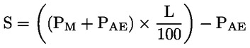
where:
S is the dynamometer setting [kW],
PM is the maximum observed or declared power at the test speed under the test conditions (see Appendix 2 of Annex VII) [kW],
PAE is the declared total power absorbed by any auxiliary fitted for the test [kW] and not required by Appendix 3 of Annex VII,
L is the percent torque specified for the test mode.
If the ratio

the value of PAE may be verified by the technical authority granting type-approval.
3. TEST RUN
3.1. Installation of the measuring equipment
The instrumentation and sampling probes shall be installed as required. When using a full flow dilution system for exhaust gas dilution, the tailpipe shall be connected to the system.
3.2. Starting the dilution system and engine
The dilution system and the engine shall be started and warmed up until all temperatures and pressures have stabilised at full load and rated speed (section 3.5.2).
3.3. Adjustment of the dilution ratio
The total dilution ratio shall not be less than four.
For CO2 or NOx concentration controlled systems, the CO2 or NOx content of the dilution air must be measured at the beginning and at the end of each test. The pre- and post-test background CO2 or NOx concentration measurements of the dilution air must be within 100 ppm or 5 ppm of each other, respectively.
When using a dilute exhaust gas analysis system, the relevant background concentrations shall be determined by sampling dilution air into a sampling bag over the complete test sequence.
Continuous (non-bag) background concentration may be taken at the minimum of three points, at the beginning, at the end, and a point near the middle of the cycle and averaged. At the manufacturer's request background measurements may be omitted.
3.4. Checking the analysers
The emission analysers shall be set at zero and spanned.
3.5. Test cycle
|
3.5.1.
|
Specification (c) of machinery according to section 1A(iii) of Annex I.
The following test cycles shall be followed in dynamometer operation on the test engine according to the given type of machinery:
cycle D (
25
) : engines with constant speed and intermittent load such as generating sets;
cycle G1 : non-hand-held intermediate speed applications;
cycle G2 : non-hand-held rated speed applications;
cycle G3 : hand-held applications.
3.5.1.1. Test modes and weighting factors
|
Cycle D
|
|
Mode number
|
1
|
2
|
3
|
4
|
5
|
|
|
|
|
|
|
|
Engine speed
|
Rated speed
|
Intermediate
|
Low-idle speed
|
|
Load (1) %
|
100
|
75
|
50
|
25
|
10
|
|
|
|
|
|
|
|
Weighting factor
|
0,05
|
0,25
|
0,3
|
0,3
|
0,1
|
|
|
|
|
|
|
|
Cycle G1
|
|
Mode number
|
|
|
|
|
|
1
|
2
|
3
|
4
|
5
|
6
|
|
Engine speed
|
Rated speed
|
Intermediate Speed
|
Low-idle speed
|
|
Load %
|
|
|
|
|
|
100
|
75
|
50
|
25
|
10
|
0
|
|
Weighting factor
|
|
|
|
|
|
0,09
|
0,2
|
0,29
|
0,3
|
0,07
|
0,05
|
|
Cycle G2
|
|
Mode number
|
1
|
2
|
3
|
4
|
5
|
|
|
|
|
|
6
|
|
Engine speed
|
Rated speed
|
Intermediate Speed
|
Low-idle speed
|
|
Load %
|
100
|
75
|
50
|
25
|
10
|
|
|
|
|
|
0
|
|
Weighting factor
|
0,09
|
0,2
|
0,29
|
0,3
|
0,07
|
|
|
|
|
|
0,05
|
|
Cycle G3
|
|
Mode number
|
1
|
|
|
|
|
|
|
|
|
|
2
|
|
Engine speed
|
Rated speed
|
Intermediate Speed
|
Low-idle speed
|
|
Load %
|
100
|
|
|
|
|
|
|
|
|
|
0
|
|
Weighting factor
|
0,85 (2)
|
|
|
|
|
|
|
|
|
|
0,15 (2)
|
3.5.1.2. Choosing an appropriate test cycle
If the primary end use of an engine model is known then the test cycle may be chosen based on the examples given in section 3.5.1.3. If the primary end use of an engine is uncertain then the appropriate test cycle should be chosen based upon the engine specification.
3.5.1.3. Examples (the list is not exhaustive)
Typical examples are for:
cycle D:
generating sets with intermittent load including generating sets on board ships and trains (not for propulsion), refrigerating units, welding sets;
cycle G1:
front or rear engines riding lawn mowers;
pedestrian-controlled rotary or cylinder lawn mowers;
cycle G2:
portable generators, pumps, welders and air compressors;
may also include lawn and garden equipment, which operate at engine rated speed;
cycle G3:
|
|
3.5.2.
|
Conditioning of the engine Warming up of the engine and the system shall be at maximum speed and torque in order to stabilise the engine parameters according to the recommendations of the manufacturer.
Note: The conditioning period should also prevent the influence of deposits from a former test in the exhaust system. There is also a required period of stabilisation between test points which has been included to minimise point to point influences.
|
|
3.5.3.
|
Test sequence Test cycles G1, G2 or G3 shall be performed in ascending order of mode number of the cycle in question. Each mode sampling time shall be at least 180 s. The exhaust emission concentration values shall be measured and recorded for the last 120 s of the respective sampling time. For each measuring point, the mode length shall be of sufficient duration to achieve thermal stability of the engine prior to the start of sampling. The mode length shall be recorded and reported.
(a) For engines tested with the dynamometer speed control test configuration: During each mode of the test cycle after the initial transition period, the specified speed shall be held to within ± 1 % of rated speed or ± 3 min-1 whichever is greater except for low idle which shall be within the tolerances declared by the manufacturer. The specified torque shall be held so that the average over the period during which the measurements are being taken is within ± 2 % of the maximum torque at the test speed.
(b) For engines tested with the dynamometer load control test configuration: During each mode of the test cycle after the initial transition period, the specified speed shall be within ± 2 % of rated speed or ± 3 min-1 whichever is greater, but shall in any case be held within ± 5 %, except for low idle which shall be within the tolerances declared by the manufacturer.
During each mode of the test cycle where the prescribed torque is 50 % or greater of the maximum torque at the test speed the specified average torque over the data acquisition period shall be held within ± 5 % of the prescribed torque. During modes of the test cycle where the prescribed torque is less than 50 % of the maximum torque at the test speed the specified average torque over the data acquisition period shall be held within ± 10 % of the prescribed torque or ± 0,5 Nm whichever is greater.
|
|
3.5.4.
|
Analyser response The output of the analysers shall be recorded on a strip chart recorder or measured with an equivalent data acquisition system with the exhaust gas flowing through the analysers at least during the last 180 s of each mode. If bag sampling is applied for the diluted CO and CO2 measurement (see Appendix 1, section 1.4.4), a sample shall be bagged during the last 180 s of each mode, and the bag sample analysed and recorded.
|
|
3.5.5.
|
Engine conditions The engine speed and load, intake air temperature and fuel flow shall be measured for each mode once the engine has been stabilised. Any additional data required for calculation shall be recorded (see Appendix 3, sections 1.1 and 1.2).
|
3.6. Rechecking the analysers
After the emission test a zero gas and the same span gas shall be used for re-checking. The test shall be considered acceptable if the difference between the two measuring results is less than 2 %.
Appendix 1
1. MEASUREMENT AND SAMPLING PROCEDURES
Gaseous components emitted by the engine submitted for testing shall be measured by the methods described in Annex VI. The methods of Annex VI describe the recommended analytical systems for the gaseous emissions (section 1.1).
1.1. Dynamometer specification
An engine dynamometer with adequate characteristics to perform the test cycles described in Annex IV, section 3.5.1 shall be used. The instrumentation for torque and speed measurement shall allow the measurement of the shaft power within the given limits. Additional calculations may be necessary.
The accuracy of the measuring equipment must be such that the maximum tolerances of the figures given in section 1.3 are not exceeded.
1.2. Fuel flow and total diluted flow
Fuel flow meters with the accuracy defined in section 1.3 shall be used to measure the fuel flow that will be used to calculate emissions (Appendix 3). When using a full flow dilution system, the total flow of the dilute exhaust (GTOTW) shall be measured with a PDP or CFV — Annex VI, section 1.2.1.2. The accuracy shall conform to the provisions of Annex III, Appendix 2, section 2.2.
1.3. Accuracy
The calibration of all measuring instruments shall be traceable to national (international) standards and comply with the requirements given in tables 2 and 3.
Table 2 — Permissible deviations of instruments for engine related parameters
|
No
|
Item
|
Permissible deviation
|
|
1
|
Engine speed
|
± 2 % of the reading or ± 1 % of engine's max value whichever is larger
|
|
2
|
Torque
|
± 2 % of the reading or ± 1 % of engine's max value whichever is larger
|
|
3
|
Fuel consumption (1)
|
± 2 % of engine's max value
|
|
4
|
Air consumption (1)
|
± 2 % of the reading or ± 1 % of engine's max value whichever is larger
|
|
(1) The calculations of the exhaust emissions as described in this Directive are, in some cases, based on different measurement and/or calculation methods. Because of limited total tolerances for the exhaust emission calculation, the allowable values for some items, used in the appropriate equations, must be smaller than the allowed tolerances given in ISO 3046-3.
|
Table 3 — Permissible deviations of instruments for other essential parameters
|
No
|
Item
|
Permissible deviation
|
|
1
|
Temperatures ≤ 600 K
|
± 2 K absolute
|
|
2
|
Temperatures ≥ 600 K
|
± 1 % of reading
|
|
3
|
Exhaust gas pressure
|
± 0,2 kPa absolute
|
|
4
|
Inlet manifold depressions
|
± 0,05 kPa absolute
|
|
5
|
Atmospheric pressure
|
± 0,1 kPa absolute
|
|
6
|
Other pressures
|
± 0,1 kPa absolute
|
|
7
|
Relative humidity
|
± 3 % absolute
|
|
8
|
Absolute humidity
|
± 5 % of reading
|
|
9
|
Dilution air flow
|
± 2 % of reading
|
|
10
|
Diluted exhaust gas flow
|
± 2 % of reading
|
1.4. Determination of the gaseous components
1.4.1. General analyser specifications
The analysers shall have a measuring range appropriate for the accuracy required for measuring the concentrations of the exhaust gas components (section 1.4.1.1). It is recommended that the analysers be operated such that the measured concentration falls between 15 % and 100 % of full scale.
If the full scale value is 155 ppm (or ppm C) or less or if read-out systems (computers, data loggers) that provide sufficient accuracy and resolution below 15 % of full scale are used concentrations below 15 % of full scale are also acceptable. In this case, additional calibrations are to be made to ensure the accuracy of the calibration curves — Appendix 2, section 1.5.5.2, of this Annex.
The electromagnetic compatibility (EMC) of the equipment shall be on a level as to minimise additional errors.
1.4.1.1. Accuracy
The analyser shall not deviate from the nominal calibration point by more than ± 2 % of the reading over the whole measurement range except zero, and ± 0,3 % of full scale at zero. The accuracy shall be determined according to the calibration requirements laid down in section 1.3.
1.4.1.2. Repeatability
The repeatability, shall be such that 2,5 times the standard deviation of 10 repetitive responses to a given calibration or span gas is not greater than ± 1 % of full scale concentration for each range used above 100 ppm (or ppmC) or ± 2 % of each range used below 100 ppm (or ppmC).
1.4.1.3. Noise
The analyser peak-to-peak response to zero and calibration or span gases over any 10-s period shall not exceed 2 % of full scale on all ranges used.
1.4.1.4. Zero drift
Zero response is defined as the mean response, including noise, to a zero gas during a 30-s time interval. The drift of the zero response during a one-hour period shall be less than 2 % of full scale on the lowest range used.
1.4.1.5. Span drift
Span response is defined as the mean response, including noise, to a span gas during a 30-s time interval. The drift of the span response during a one-hour period shall be less than 2 % of full scale on the lowest range used.
1.4.2. Gas drying
Exhaust gases may be measured wet or dry. Any gas-drying device, if used, must have a minimal effect on the concentration of the measured gases. Chemical dryers are not an acceptable method of removing water from the sample.
1.4.3. Analysers
Sections 1.4.3.1 to 1.4.3.5 describe the measurement principles to be used. A detailed description of the measurement systems is given in Annex VI.
The gases to be measured shall be analysed with the following instruments. For non-linear analysers, the use of linearising circuits is permitted.
1.4.3.1. Carbon monoxide (CO) analysis
The carbon monoxide analyser shall be of the non-dispersive infrared (NDIR) absorption type.
1.4.3.2. Carbon dioxide (CO2) analysis
The carbon dioxide analyser shall be of the non-dispersive infrared (NDIR) absorption type.
1.4.3.3. Oxygen (O2) analysis
Oxygen analysers shall be of the paramagnetic detector (PMD), zirconium dioxide (ZRDO) or electrochemical sensor (ECS) types.
Note: Zirconium dioxide sensors are not recommended when HC and CO concentrations are high such as for lean burn spark ignited engines. Electrochemical sensors shall be compensated for CO2 and NOX interference.
1.4.3.4. Hydrocarbon (HC) analysis
For direct gas sampling the hydrocarbon analyser shall be of the heated flame ionisation detector (HFID) type with detector, valves, pipework, etc., heated so as to maintain a gas temperature of 463 K ± 10 K (190 oC ± 10 oC).
For diluted gas sampling the hydrocarbon analyser shall be either the heated flame ionisation detector (HFID) type or the flame ionisation detector (FID) type.
1.4.3.5. Oxides of nitrogen (NOx) analysis
The oxides of nitrogen analyser shall be of the chemiluminescent detector (CLD) or heated chemiluminescent detector (HCLD) type with a NO2/NO converter, if measured on a dry basis. If measured on a wet basis, a HCLD with converter maintained above 328 K (55 oC) shall be used, provided the water quench check (Annex III, Appendix 2, section 1.9.2.2) is satisfied. For both CLD and HCLD, the sampling path shall be maintained at a wall temperature of 328 K to 473 K (55 oC to 200 oC) up to the converter for dry measurement, and up to the analyser for wet measurement.
1.4.4. Sampling for gaseous emissions
If the composition of the exhaust gas is influenced by any exhaust after-treatment system, the exhaust sample shall be taken downstream of this device.
The exhaust sampling probe should be in a high pressure side of the muffler, but as far from the exhaust port as possible. To ensure complete mixing of the engine exhaust before sample extraction, a mixing chamber may be optionally inserted between the muffler outlet and the sample probe. The internal volume of the mixing chamber must be not less than 10 times the cylinder displacement of the engine under test and should be roughly equal dimensions in height, width and depth, being similar to a cube. The mixing chamber size should be kept as small as practicable and should be coupled as close as possible to the engine. The exhaust line leaving the mixing chamber of muffler should extend at least 610 mm beyond the sample probe location and be of sufficient size to minimise back pressure. The temperature of the inner surface of the mixing chamber must be maintained above the dew point of the exhaust gases and a minimum temperature of 338 oK (65 oC) is recommended.
All components may optionally be measured directly in the dilution tunnel, or by sampling into a bag and subsequent measurement of the concentration in the sampling bag.
Appendix 2
1. CALIBRATION OF THE ANALYTICAL INSTRUMENTS
1.1. Introduction
Each analyser shall be calibrated as often as necessary to fulfil the accuracy requirements of this standard. The calibration method that shall be used is described in this paragraph for the analysers indicated in Appendix 1, section 1.4.3.
1.2. Calibration gases
The shelf life of all calibration gases must be respected.
The expiry date of the calibration gases stated by the manufacturer shall be recorded.
1.2.1 Pure gases
The required purity of the gases is defined by the contamination limits given below. The following gases must be available for operation:
— purified nitrogen (contamination ≤ 1 ppm C, ≤ 1 ppm CO, ≤ 400 ppm CO2, ≤ 0,1 ppm NO),
— purified oxygen (purity > 99,5 Vol.-% O2),
— hydrogen-helium mixture (40 ± 2 % hydrogen, balance helium); contamination ≤ 1 ppm C, ≤ 400 ppm CO2,
— purified synthetic air (contamination ≤ 1 ppm C, ≤ 1 ppm CO, ≤ 400 ppm CO2, ≤ 0,1 ppm NO (oxygen content between 18 % and 21 % vol).
1.2.2 Calibration and span gases
Mixture of gases having the following chemical compositions shall be available:
— C3H8 and purified synthetic air (see section 1.2.1),
— CO and purified nitrogen,
— and purified nitrogen (the amount of NO2 contained in this calibration gas must not exceed 5 % of the NO content),
— CO2 and purified nitrogen,
— CH4 and purified synthetic air,
— C2H6 and purified synthetic air.
Note: Other gas combinations are allowed provided the gases do not react with one another.
The true concentration of a calibration and span gas shall be within ± 2 % of the nominal value. All concentrations of calibration gas shall be given on a volume basis (volume percent or volume ppm).
The gases used for calibration and span may also be obtained by means of precision blending devices (gas dividers), diluting with purified N2 or with purified synthetic air. The accuracy of the mixing device must be such that the concentration of the diluted calibration gases is accurate to within ± 1,5 %. This accuracy implies that primary gases used for blending must be known to an accuracy of at least ± 1 %, traceable to national or international gas standards. The verification shall be performed at between 15 % and 50 % of full scale for each calibration incorporating a blending device.
Optionally, the blending device may be checked with an instrument, which by nature is linear, e.g. using NO gas with a CLD. The span value of the instrument shall be adjusted with the span gas directly connected to the instrument. The blending device shall be checked at the used settings and the nominal value shall be compared to the measured concentration of the instrument. This difference shall in each point be within ± 0,5 % of the nominal value.
1.2.3 Oxygen interference check
Oxygen interference check gases shall contain propane with 350 ppm C ± 75 ppm C hydrocarbon. The concentration value shall be determined to calibration gas tolerances by chromatographic analysis of total hydrocarbons plus impurities or by dynamic blending. Nitrogen shall be the predominant diluent with the balance oxygen. Blend required for gasoline-fuelled engine testing is as follows:
|
O2 interference concentration
|
Balance
|
|
10 (9 to 11)
|
Nitrogen
|
|
5 (4 to 6)
|
Nitrogen
|
|
0 (0 to 1)
|
Nitrogen.
|
1.3. Operating procedure for analysers and sampling system
The operating procedure for analysers shall follow the start-up and operating instructions of the instrument manufacturer. The minimum requirements given in sections 1.4 to 1.9 shall be included. For laboratory instruments such as GC and high performance liquid chromatography (HPLC) only section 1.5.4 shall apply.
1.4. Leakage test
A system leakage test shall be performed. The probe shall be disconnected from the exhaust system and the end plugged. The analyser pump shall be switched on. After an initial stabilisation period all flow meters should read zero. If not, the sampling lines shall be checked and the fault corrected.
The maximum allowable leakage rate on the vacuum side shall be 0,5 % of the in-use flow rate for the portion of the system being checked. The analyser flows and bypass flows may be used to estimate the in-use flow rates.
Alternatively, the system may be evacuated to a pressure of at least 20 kPa vacuum (80 kPa absolute). After an initial stabilisation period the pressure increase δp (kPa/min) in the system shall not exceed:

Where:
Vsyst = system volume [l]
fr = system flow rate [l/min]
Another method is the introduction of a concentration step change at the beginning of the sampling line by switching from zero to span gas. If after an adequate period of time the reading shows a lower concentration compared to the introduced concentration, this points to calibration or leakage problems.
1.5. Calibration procedure
1.5.1 Instrument assembly
The instrument assembly shall be calibrated and calibration curves checked against standard gases. The same gas flow rates shall be used as when sampling exhaust gas.
1.5.2. Warming-up time
The warming-up time should be according to the recommendations of the manufacturer. If not specified, a minimum of two hours is recommended for warming-up the analysers.
1.5.3. NDIR and HFID analyser
The NDIR analyser shall be tuned, as necessary, and the combustion flame of the HFID analyser shall be optimised (section 1.9.1).
1.5.4. GC and HPCL
Both instruments shall be calibrated according to good laboratory practice and the recommendations of the manufacturer.
1.5.5. Establishment of the calibration curves
1.5.5.1. General guidelines
(a) Each normally used operating range shall be calibrated.
(b) Using purified synthetic air (or nitrogen), the CO, CO2, NOx and HC analysers shall be set at zero.
(c) The appropriate calibration gases shall be introduced to the analysers, the values recorded, and the calibration curves established.
(d) For all instrument ranges except for the lowest range, the calibration curve shall be established by at least 10 calibration points (excluding zero) equally spaced. For the lowest range of the instrument, the calibration curve shall be established by at least 10 calibration points (excluding zero) spaced so that half of the calibration points are placed below 15 % of the analyser's full scale and the rest are placed above 15 % of full scale. For all ranges the highest nominal concentration must be equal to or higher than 90 % of full scale.
(e) The calibration curve shall be calculated by the method of least squares. A best-fit linear or non-linear equation may be used.
(f) The calibration points must not differ from the least-squares best-fit line by more than ± 2 % of reading or ± 0,3 % of full scale whichever is larger.
(g) The zero setting shall be rechecked and the calibration procedure repeated, if necessary.
1.5.5.2. Alternative methods
If it can be shown that alternative technology (e.g. computer, electronically controlled range switch, etc.) can give equivalent accuracy, then these alternatives may be used.
1.6. Verification of the calibration
Each normally used operating range shall be checked prior to each analysis in accordance with the following procedure.
The calibration is checked by using a zero gas and a span gas whose nominal value is more than 80 % of full scale of the measuring range.
If, for the two points considered, the value found does not differ by more than ± 4 % of full scale from the declared reference value, the adjustment parameters may be modified. Should this not be the case, the span gas shall be verified or a new calibration curve shall be established in accordance with section 1.5.5.1.
1.7. Calibration of tracer gas analyser for exhaust flow measurement
The analyser for measurement of the tracer gas concentration shall be calibrated using the standard gas.
The calibration curve shall be established by at least 10 calibration points (excluding zero) spaced so that half of the calibration points are placed between 4 % to 20 % of the analyser's full scale and the rest are in between 20 % and 100 % of the full scale. The calibration curve shall be calculated by the method of least squares.
The calibration curve must not differ by more than ± 1 % of the full scale from the nominal value of each calibration point, in the range from 20 % to 100 % of the full scale. It also must not differ by more than ± 2 % of reading from the nominal value in the range from 4 % to 20 % of the full scale. The analyser shall be set at zero and spanned prior to the test run using a zero gas and a span gas whose nominal value is more than 80 % of the analyser full scale.
1.8. Efficiency test of the NOx converter
The efficiency of the converter used for the conversion of NO2 into NO is tested as given in sections 1.8.1 to 1.8.8 (figure 1 of Annex III, Appendix 2).
1.8.1. Test set-up
Using the test set-up as shown in figure 1 of Annex III and the procedure below, the efficiency of converters can be tested by means of an ozonator.
1.8.2. Calibration
The CLD and the HCLD shall be calibrated in the most common operating range following the manufacturer's specifications using zero and span gas (the NO content of which must amount to about 80 % of the operating range and the NO2 concentration of the gas mixture to less than 5 % of the NO concentration). The NOx analyser must be in the NO mode so that the span gas does not pass through the converter. The indicated concentration has to be recorded.
1.8.3. Calculation
The efficiency of the NO x, converter is calculated as follows:
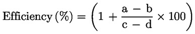
Where:
|
a
|
=
|
NOx concentration according to section 1.8.6
|
|
b
|
=
|
NOx concentration according to section 1.8.7
|
|
c
|
=
|
NO concentration according to section 1.8.4
|
|
d
|
=
|
NO concentration according to section 1.8.5.
|
1.8.4. Adding of oxygen
Via a T-fitting, oxygen or zero air is added continuously to the gas flow until the concentration indicated is about 20 % less than the indicated calibration concentration given in section 1.8.2. (The analyser is in the NO mode.)
The indicated concentration (c) shall be recorded. The ozonator is kept deactivated throughout the process.
1.8.5 Activation of the ozonator
The ozonator is now activated to generate enough ozone to bring the NO concentration down to about 20 % (minimum 10 %) of the calibration concentration given in section 1.8.2. The indicated concentration (d) shall be recorded. (The analyser is in the NO mode.)
1.8.6 NOx mode
The NO analyser is then switched to the NOx mode so that the gas mixture (consisting of NO, NO2, O2 and N2) now passes through the converter. The indicated concentration (a) shall be recorded. (The analyser is in the NOx mode.)
1.8.7. Deactivation of the ozonator
The ozonator is now deactivated. The mixture of gases described in section 1.8.6 passes through the converter into the detector. The indicated concentration (b) shall be recorded. (The analyser is in the NOx mode.)
1.8.8. NO mode
Switched to NO mode with the ozonator deactivated, the flow of oxygen or synthetic air is also shut off. The NOx reading of the analyser shall not deviate by more than ± 5 % from the value measured according to section 1.8.2. (The analyser is in the NO mode.)
1.8.9. Test interval
The efficiency of the converter must be checked monthly.
1.8.10. Efficiency requirement
The efficiency of the converter shall not be less than 90 %, but a higher efficiency of 95 % is strongly recommended.
Note: If, with the analyser in the most common range, the ozonator cannot give a reduction from 80 % to 20 % according to section 1.8.5, then the highest range which will give the reduction shall be used.
1.9. Adjustment of the FID
1.9.1. Optimisation of the detector response
The HFID must be adjusted as specified by the instrument manufacturer. A propane in air span gas should be used to optimise the response on the most common operating range.
With the fuel and airflow rates set at the manufacturer's recommendations, a 350 ± 75 ppm C span gas shall be introduced to the analyser. The response at a given fuel flow shall be determined from the difference between the span gas response and the zero gas response. The fuel flow shall be incrementally adjusted above and below the manufacturer's specification. The span and zero response at these fuel flows shall be recorded. The difference between the span and zero response shall be plotted and the fuel flow adjusted to the rich side of the curve. This is the initial flow rate setting, which may need further optimisation depending on the results of the hydrocarbon response factor and the oxygen interference check according to sections 1.9.2 and 1.9.3.
If the oxygen interference or the hydrocarbon response factors do not meet the following specifications, the airflow shall be incrementally adjusted above and below the manufacturer's specifications, sections 1.9.2 and 1.9.3 should be repeated for each flow.
1.9.2. Hydrocarbon response factors
The analyser shall be calibrated using propane in air and purified synthetic air, according to section 1.5.
Response factors shall be determined when introducing an analyser into service and after major service intervals. The response factor (Rf) for a particular hydrocarbon species is the ratio of the FID C1 reading to the gas concentration in the cylinder expressed by ppm C1.
The concentration of the test gas must be at a level to give a response of approximately 80 % of full scale. The concentration must be known to an accuracy of ± 2 % in reference to a gravimetric standard expressed in volume. In addition, the gas cylinder must be preconditioned for 24 hours at a temperature of 298 K (25 oC) ± 5 K.
The test gases to be used and the recommended relative response factor ranges are as follows:
— methane and purified synthetic air: 1,00 ≤ Rf ≤ 1,15
— propylene and purified synthetic air: 0,90 ≤ Rf ≤ 1,1
— toluene and purified synthetic air: 0,90 ≤ Rf ≤ 1,10.
These values are relative to the response factor (Rf) of 1,00 for propane and purified synthetic air.
1.9.3. Oxygen interference check
The oxygen interference check shall be determined when introducing an analyser into service and after major service intervals. A range shall be chosen where the oxygen interference check gases will fall in the upper 50 %. The test shall be conducted with the oven temperature set as required. The oxygen interference gases are specified in section 1.2.3.
(a) The analyser shall be zeroed.
(b) The analyser shall be spanned with the 0 % oxygen blend for gasoline fuelled engines.
(c) The zero response shall be rechecked. If it has changed more than 0,5 % of full scale subsections (a) and (b) of this section shall be repeated.
(d) The 5 % and 10 % oxygen interference check gases shall be introduced.
(e) The zero response shall be rechecked. If it has changed more than ± 1 % of full scale, the test shall be repeated.
(f) The oxygen interference (% O2I) shall be calculated for each mixture in step (d) as follows:
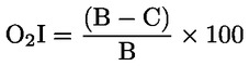

where:
|
A
|
=
|
hydrocarbon concentration (ppm C) of the span gas used in subsection (b)
|
|
B
|
=
|
hydrocarbon concentration (ppm C) of the oxygen interference check gases used in subsection (d)
|
|
D
|
=
|
percent of full scale analyser response due to A
|
(g) The % of oxygen interference (% O2I) shall be less than ± 3 % for all required oxygen interference check gases prior to testing.
(h) If the oxygen interference is greater than ± 3 %, the air flow above and below the manufacturer's specifications shall be incrementally adjusted, repeating section 1.9.1 for each flow.
(i) If the oxygen interference is greater than ± 3 %, after adjusting the air flow, the fuel flow and thereafter the sample flow shall be varied, repeating section 1.9.1 for each new setting.
(j) If the oxygen interference is still greater than ± 3 %, the analyser, FID fuel, or burner air shall be repaired or replaced prior to testing. This section shall then be repeated with the repaired or replaced equipment or gases.
1.10. Interference effects with CO, CO2, NOX and O2 analysers
Gases other than the one being analysed can interfere with the reading in several ways. Positive interference occurs in NDIR and PMD instruments where the interfering gas gives the same effect as the gas being measured, but to a lesser degree. Negative interference occurs in NDIR instruments by the interfering gas broadening the absorption band of the measured gas, and in CLD instruments by the interfering gas quenching the radiation. The interference checks in sections 1.10.1 and 1.10.2 shall be performed prior to an analyser's initial use and after major service intervals, but at least once per year.
1.10.1. CO analyser interference check
Water and CO2 can interfere with the CO analyser performance. Therefore a CO2 span gas having a concentration of 80 % to 100 % of full scale of the maximum operating range used during testing shall be bubbled through water at room temperature and the analyser response recorded. The analyser response must not be more than 1 % of full scale for ranges equal to or above 300 ppm or more than 3 ppm for ranges below 300 ppm.
1.10.2. NOx analyser quench checks
The two gases of concern for CLD (and HCLD) analysers are CO2 and water vapour. Quench responses of these gases are proportional to their concentrations, and therefore require test techniques to determine the quench at the highest expected concentrations experienced during testing.
1.10.2.1. CO2 quench check
A CO2 span gas having a concentration of 80 % to 100 % of full scale of the maximum operating range shall be passed through the NDIR analyser and the CO2 value recorded as A. It shall then be diluted approximately 50 % with NO span gas and passed through the NDIR and (H)CLD with the CO2 and NO values recorded as B and C, respectively. The CO2 shall be shut off and only the NO span gas is passed through the (H)CLD and the NO value recorded as D.
The quench, which shall not be greater than 3 % full scale, shall be calculated as follows:

where:
|
A
|
:
|
undiluted CO2 concentration measured with NDIR %
|
|
B
|
:
|
diluted CO2 concentration measured with NDIR %
|
|
C
|
:
|
diluted NO concentration measured with CLD ppm
|
|
D
|
:
|
undiluted NO concentration measured with CLD ppm
|
Alternative methods of diluting and quantifying CO2 and NO span gas values, such as dynamic/mixing/blending, can be used.
1.10.2.2. Water quench check
This check applies to wet gas concentration measurements only. Calculation of water quench must consider dilution of the NO span gas with water vapour and scaling of water vapour concentration of the mixture to that expected during testing.
A NO span gas having a concentration of 80 % to 100 % of full scale to the normal operating range shall be passed through the (H)CLD and the NO value recorded as D. The NO span gas shall then be bubbled through water at room temperature and passed through the (H)CLD and the NO value recorded as C. The water temperature shall be determined and recorded as F. The mixture's saturation vapour pressure that corresponds to the bubbler water temperature (F) shall be determined and recorded as G. The water vapour concentration (in %) of the mixture shall be calculated as follows:

and recorded as H. The expected diluted NO span gas (in water vapour) concentration shall be calculated as follows:

and recorded as De.
The water quench shall not be greater than 3 % and shall be calculated as follows:

where:
De : expected diluted NO concentration (ppm)
C : diluted NO concentration (ppm)
Hm : maximum water vapour concentration
H : actual water vapour concentration (%).
Note: It is important that the NO span gas contains minimal NO2 concentration for this check, since absorption of NO2 in water has not been accounted for in the quench calculations.
1.10.3. O2 analyser interference
Instrument response of a PMD analyser caused by gases other than oxygen is comparatively slight. The oxygen equivalents of the common exhaust gas constituents are shown in table 1.
Tabel 1 — Oxygen equivalents
|
Gas
|
O2 equivalent %
|
|
Carbon dioxide (CO2)
|
– 0,623
|
|
Carbon monoxide (CO)
|
– 0,354
|
|
Nitrogen oxide (NO)
|
+ 44,4
|
|
Nitrogen dioxide (NO2)
|
+ 28,7
|
|
Water (H2O)
|
– 0,381
|
The observed oxygen concentration shall be corrected by the following formula if high precision measurements are to be done:

1.11. Calibration intervals
The analysers shall be calibrated according to section 1.5 at least every three months or whenever a system repair or change is made that could influence calibration.
Appendix 3
1. DATA EVALUATION AND CALCULATIONS
1.1. Gaseous emissions evaluation
For the evaluation of the gaseous emissions, the chart reading for a minimum of the last 120 s of each mode shall be averaged, and the average concentrations (conc) of HC, CO, NOx and CO2 during each mode shall be determined from the average chart readings and the corresponding calibration data. A different type of recording can be used if it ensures an equivalent data acquisition.
The average background concentration (concd) may be determined from the bag readings of the dilution air or from the continuous (non-bag) background reading and the corresponding calibration data.
1.2. Calculation of the gaseous emissions
The finally reported test results shall be derived through the following steps.
1.2.1. Dry/wet correction
The measured concentration, if not already measured on a wet basis, shall be converted to a wet basis:

For the raw exhaust gas:

where α is the hydrogen to carbon ratio in the fuel.
The H2 concentration in the exhaust shall be calculated:

The factor kw2 shall be calculated:

with Ha absolute humidity of the intake air as g of water per kg of dry air.
For the diluted exhaust gas:
for wet CO2 measurement:

or, for dry CO2 measurement:
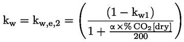
where α is the hydrogen to carbon ratio in the fuel.
The factor k w1 shall be calculated from the following equations:

where:
Hdabsolute humidity of the dilution air, g of water per kg of dry air
Haabsolute humidity of the intake air, g of water per kg of dry air

For the dilution air:

The factor k w1 shall be calculated from the following equations:


where:
|
Hd
|
absolute humidity of the dilution air, g of water per kg of dry air
|
|
Ha
|
absolute humidity of the intake air, g of water per kg of dry air
|

For the intake air (if different from the dilution air):

The factor kw2 shall be calculated from the following equations:

with Ha absolute humidity of the intake air, g of water per kg of dry air.
1.2.2. Humidity correction for NOx
As the NOx emission depends on ambient air conditions, the NOx concentration shall be multiplied by the factor KH taking into account humidity:


with Ha absolute humidity of the intake air as g of water per kg of dry air.
1.2.3. Calculation of emission mass flow rate
The emission mass flow rates Gasmass [g/h] for each mode shall be calculated as follows.
(a) For the raw exhaust gas (
28
):

where:
GFUEL [kg/h] is the fuel mass flow rate;
MWGas [kg/kmol] is the molecular weight of the individual gas shown in table 1;
Table 1 — Molecular weights
|
Gas
|
MWGas [kg/kmol]
|
|
NOx
|
46,01
|
|
CO
|
28,01
|
|
HC
|
MWHC = MWFUEL
|
|
CO2
|
44,01
|
— MWFUEL = 12,011 + α × 1,00794 + β × 15,9994 [kg/kmole] is the fuel molecular weight with α hydrogen to carbon ratio and β oxygen to carbon ratio of the fuel (
29
);
— CO2AIR is the CO2 concentration in the intake air (that is assumed equal to 0,04 % if not measured).
(b) For the diluted exhaust gas (28) :

where:
— GTOTW [kg/h] is the diluted exhaust gas mass flow rate on wet basis that, when using a full flow dilution system, shall be determined according to Annex III, Appendix 1, section 1.2.4,
— concc is the background corrected concentration:
—

— with
—
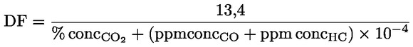
The u coefficient is shown in table 2.
Table 2 — Values of u coefficient
|
Gas
|
u
|
conc
|
|
NOx
|
0,001587
|
ppm
|
|
CO
|
0,000966
|
ppm
|
|
HC
|
0,000479
|
ppm
|
|
CO2
|
15,19
|
%
|
Values of the u coefficient are based upon a molecular weight of the dilute exhaust gases equal to 29 [kg/kmol]; the value of u for HC is based upon an average carbon to hydrogen ratio of 1:1,85.
1.2.4. Calculation of specific emissions
The specific emission (g/kWh) shall be calculated for all individual components:

where Pi = PM,i + PAE,i
When auxiliaries, such as cooling fan or blower, are fitted for the test, the power absorbed shall be added to the results except for engines where such auxiliaries are an integral part of the engine. The fan or blower power shall be determined at the speeds used for the tests either by calculation from standard characteristics or by practical tests (Appendix 3 of Annex VII).
The weighting factors and the number of the n modes used in the above calculation are shown in Annex IV, section 3.5.1.1.
2. EXAMPLES
2.1. Raw exhaust gas data from a four-stroke SI engine
With reference to the experimental data (table 3), calculations are carried out first for mode 1 and then are extended to other test modes using the same procedure.
Table 3 — Experimental data of a four-stroke SI engine
|
Mode
|
|
1
|
2
|
3
|
4
|
5
|
6
|
|
Engine speed
|
min-1
|
2 550
|
2 550
|
2 550
|
2 550
|
2 550
|
1 480
|
|
Power
|
kW
|
9,96
|
7,5
|
4,88
|
2,36
|
0,94
|
0
|
|
Load percent
|
%
|
100
|
75
|
50
|
25
|
10
|
0
|
|
Weighting factors
|
—
|
0,090
|
0,200
|
0,290
|
0,300
|
0,070
|
0,050
|
|
Barometric pressure
|
kPa
|
101,0
|
101,0
|
101,0
|
101,0
|
101,0
|
101,0
|
|
Air temperature
|
oC
|
20,5
|
21,3
|
22,4
|
22,4
|
20,7
|
21,7
|
|
Air relative humidity
|
%
|
38,0
|
38,0
|
38,0
|
37,0
|
37,0
|
38,0
|
|
Air absolute humidity
|
gH20/kgair
|
5,696
|
5,986
|
6,406
|
6,236
|
5,614
|
6,136
|
|
CO dry
|
ppm
|
60 995
|
40 725
|
34 646
|
41 976
|
68 207
|
37 439
|
|
NOx wet
|
ppm
|
726
|
1 541
|
1 328
|
377
|
127
|
85
|
|
HC wet
|
ppm C1
|
1 461
|
1 308
|
1 401
|
2 073
|
3 024
|
9 390
|
|
CO2 dry
|
% Vol.
|
11,4098
|
12,691
|
13,058
|
12,566
|
10,822
|
9,516
|
|
Fuel mass flow
|
kg/h
|
2,985
|
2,047
|
1,654
|
1,183
|
1,056
|
0,429
|
|
Fuel H/C ratio α
|
—
|
1,85
|
1,85
|
1,85
|
1,85
|
1,85
|
1,85
|
|
Fuel O/C ratio β
|
|
0
|
0
|
0
|
0
|
0
|
0
|
2.1.1. Dry/wet correction factor kw
The dry/wet correction factor kw shall be calculated for converting dry CO and CO2 measurements on a wet basis:

where:

and


Table 4 — CO and CO2 wet values according to different test modes
|
Mode
|
|
1
|
2
|
3
|
4
|
5
|
6
|
|
H2 dry
|
%
|
2,450
|
1,499
|
1,242
|
1,554
|
2,834
|
1,422
|
|
kw2
|
—
|
0,009
|
0,010
|
0,010
|
0,010
|
0,009
|
0,010
|
|
kw
|
—
|
0,872
|
0,870
|
0,869
|
0,870
|
0,874
|
0,894
|
|
CO wet
|
ppm
|
53 198
|
35 424
|
30 111
|
36 518
|
59 631
|
33 481
|
|
CO2 wet
|
%
|
9,951
|
11,039
|
11,348
|
10,932
|
9,461
|
8,510
|
2.1.2. HC emissions

Where:


Table 5 — HC emissions [g/h] according to different test modes
|
Mode
|
1
|
2
|
3
|
4
|
5
|
6
|
|
HCmass
|
28,361
|
18,248
|
16,026
|
16,625
|
20,357
|
31,578
|
2.1.3. NOx emissions
At first the humidity correction factor KH of NOx emissions shall be calculated:


Table 6 — Humidity correction factor KH of NOx emissions according to different modes
|
Mode
|
1
|
2
|
3
|
4
|
5
|
6
|
|
KH
|
0,850
|
0,860
|
0,874
|
0,868
|
0,847
|
0,865
|
Then NOxmass [g/h] shall be calculated:


Table 7 — NOx emissions [g/h] according to the different test modes
|
Mode
|
1
|
2
|
3
|
4
|
5
|
6
|
|
NOxmass
|
39,717
|
61,291
|
44,013
|
8,703
|
2,401
|
0,820
|
2.1.4 CO emissions


Table 8 — CO emissions [g/h] according to different test modes
|
Mode
|
1
|
2
|
3
|
4
|
5
|
6
|
|
COmass
|
2 084,588
|
997,638
|
695,278
|
591,183
|
810,334
|
227,285
|
2.1.5. CO2 emissions


Table 9 — CO2 emissions [g/h] according to different test modes
|
Mode
|
1
|
2
|
3
|
4
|
5
|
6
|
|
CO2mass
|
6 126,806
|
4 884,739
|
4 117,202
|
2 780,662
|
2 020,061
|
907,648
|
2.1.6. Specific emissions
The specific emission (g/kWh) shall be calculated for all individual components:

Table 10 —Emissions [g/h] and weighting factors according to the test modes
|
Mode
|
|
1
|
2
|
3
|
4
|
5
|
6
|
|
HCmass
|
g/h
|
28,361
|
18,248
|
16,026
|
16,625
|
20,357
|
31,578
|
|
NOxmass
|
g/h
|
39,717
|
61,291
|
44,013
|
8,703
|
2,401
|
0,820
|
|
COmass
|
g/h
|
2 084,588
|
997,638
|
695,278
|
591,183
|
810,334
|
227,285
|
|
CO2mass
|
g/h
|
6 126,806
|
4 884,739
|
4 117,202
|
2 780,662
|
2 020,061
|
907,648
|
|
Power PI
|
kW
|
9,96
|
7,50
|
4,88
|
2,36
|
0,94
|
0
|
|
Weighting factors WFI
|
—
|
0,090
|
0,200
|
0,290
|
0,300
|
0,070
|
0,050
|


2.2. Raw exhaust gas data from a two-stroke SI engine
With reference to the experimental data (table 11), calculations shall be carried out first for mode 1 and then extended to the other test mode using the same procedure.
Table 11 — Experimental data of a two-stroke SI engine
|
Mode
|
|
1
|
2
|
|
Engine speed
|
min-1
|
9 500
|
2 800
|
|
Power
|
kW
|
2,31
|
0
|
|
Load percent
|
%
|
100
|
0
|
|
Weighting factors
|
—
|
0,9
|
0,1
|
|
Barometric pressure
|
kPa
|
100,3
|
100,3
|
|
Air temperature
|
oC
|
25,4
|
25
|
|
Air relative humidity
|
%
|
38,0
|
38,0
|
|
Air absolute humidity
|
gH20/kgair
|
7,742
|
7,558
|
|
CO dry
|
ppm
|
37 086
|
16 150
|
|
NOx wet
|
ppm
|
183
|
15
|
|
HC wet
|
ppmC1
|
14 220
|
13 179
|
|
CO2 dry
|
% Vol.
|
11,986
|
11,446
|
|
Fuel mass flow
|
kg/h
|
1,195
|
0,089
|
|
Fuel H/C ratio α
|
—
|
1,85
|
1,85
|
|
Fuel O/C ratio β
|
|
0
|
0
|
2.2.1 Dry/wet correction factor kw
The dry/wet correction factor kw shall be calculated for converting dry CO and CO2 measurements on a wet basis:

Where:
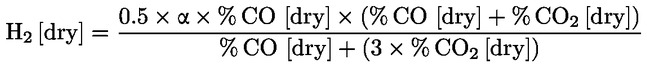


Table 12 — CO and CO2 wet values according to different test modes
|
Mode
|
|
1
|
2
|
|
H2 dry
|
%
|
1,357
|
0,543
|
|
kw2
|
—
|
0,012
|
0,012
|
|
kw
|
—
|
0,874
|
0,887
|
|
CO wet
|
ppm
|
32 420
|
14 325
|
|
CO2 wet
|
%
|
10,478
|
10,153
|
2.2.2. HC emissions

where:


Table 13 — HC emissions [g/h] according to test modes
|
Mode
|
1
|
2
|
|
HCmass
|
112,520
|
9,119
|
2.2.3. NOx emissions
The factor KH for the correction of the NOx emissions is equal to 1 for two-stroke engines:


Table 14 — NOx emissions [g/h] according to test modes
|
Mode
|
1
|
2
|
|
NOxmass
|
4,800
|
0,034
|
2.2.4. CO emissions


Table 15 — CO emissions [g/h] according to test modes
|
Mode
|
1
|
2
|
|
COmass
|
517,851
|
20,007
|
2.2.5. CO2 emissions


Table 16 — CO2 emissions [g/h] according to test modes
|
Mode
|
1
|
2
|
|
CO2mass
|
2 629,658
|
222,799
|
2.2.6. Specific emissions
The specific emission (g/kWh) shall be calculated for all individual components in the following way:

Table 17 — Emissions [g/h] and weighting factors in two test modes
|
Mode
|
|
1
|
2
|
|
HCmass
|
g/h
|
112,520
|
9,119
|
|
NOxmass
|
g/h
|
4,800
|
0,034
|
|
COmass
|
g/h
|
517,851
|
20,007
|
|
CO2mass
|
g/h
|
2 629,658
|
222,799
|
|
Power PII
|
kW
|
2,31
|
0
|
|
Weighting factors WFi
|
—
|
0,85
|
0,15
|


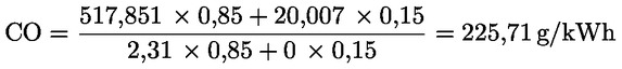

2.3. Diluted exhaust gas data from a four-stroke SI engine
With reference to the experimental data (table 18), calculations shall be carried out first for mode 1 and then extended to other test modes using the same procedure.
Table 18 — Experimental data of a four-stroke SI engine
|
Mode
|
|
1
|
2
|
3
|
4
|
5
|
6
|
|
Engine speed
|
min-1
|
3 060
|
3 060
|
3 060
|
3 060
|
3 060
|
2 100
|
|
Power
|
kW
|
13,15
|
9,81
|
6,52
|
3,25
|
1,28
|
0
|
|
Load percent
|
%
|
100
|
75
|
50
|
25
|
10
|
0
|
|
Weighting factors
|
—
|
0,090
|
0,200
|
0,290
|
0,300
|
0,070
|
0,050
|
|
Barometric pressure
|
kPa
|
980
|
980
|
980
|
980
|
980
|
980
|
|
Intake air temperature (1)
|
oC
|
25,3
|
25,1
|
24,5
|
23,7
|
23,5
|
22,6
|
|
Intake air relative humidity (1)
|
%
|
19,8
|
19,8
|
20,6
|
21,5
|
21,9
|
23,2
|
|
Intake air absolute humidity (1)
|
gH20/kgair
|
4,08
|
4,03
|
4,05
|
4,03
|
4,05
|
4,06
|
|
CO dry
|
ppm
|
3 681
|
3 465
|
2 541
|
2 365
|
3 086
|
1 817
|
|
NOx wet
|
ppm
|
85,4
|
49,2
|
24,3
|
5,8
|
2,9
|
1,2
|
|
HC wet
|
ppm C1
|
91
|
92
|
77
|
78
|
119
|
186
|
|
CO2 dry
|
% Vol
|
1,038
|
0,814
|
0,649
|
0,457
|
0,330
|
0,208
|
|
CO dry (background)
|
ppm
|
3
|
3
|
3
|
2
|
2
|
3
|
|
NOx wet (background)
|
ppm
|
0,1
|
0,1
|
0,1
|
0,1
|
0,1
|
0,1
|
|
HC wet (background)
|
ppm C1
|
6
|
6
|
5
|
6
|
6
|
4
|
|
CO2 dry (background)
|
% Vol
|
0,042
|
0,041
|
0,041
|
0,040
|
0,040
|
0,040
|
|
Dil. exh. gas mass flow GTOTW
|
kg/h
|
625,722
|
627,171
|
623,549
|
630,792
|
627,895
|
561,267
|
|
Fuel H/C ratio α
|
—
|
1,85
|
1,85
|
1,85
|
1,85
|
1,85
|
1,85
|
|
Fuel O/C ratio β
|
|
0
|
0
|
0
|
0
|
0
|
0
|
|
(1) Dilution air conditions equal to intake air conditions.
|
2.3.1. Dry/wet correction factor kw
The dry/wet correction factor kw shall be calculated for converting dry CO and CO2 measurements on a wet basis.
For the diluted exhaust gas:

where:


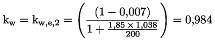


Table 19 — CO and CO2 wet values for the diluted exhaust gas according to test modes
|
Mode
|
|
1
|
2
|
3
|
4
|
5
|
6
|
|
DF
|
—
|
9,465
|
11,454
|
14,707
|
19,100
|
20,612
|
32,788
|
|
kw1
|
—
|
0,007
|
0,006
|
0,006
|
0,006
|
0,006
|
0,006
|
|
kw
|
—
|
0,984
|
0,986
|
0,988
|
0,989
|
0,991
|
0,992
|
|
CO wet
|
ppm
|
3 623
|
3 417
|
2 510
|
2 340
|
3 057
|
1 802
|
|
CO2 wet
|
%
|
1,0219
|
0,8028
|
0,6412
|
0,4524
|
0,3264
|
0,2066
|
For the dilution air:
Where the factor kw1 is the same as that already calculated for the diluted exhaust gas.
kw,d = 1 – 0,007 = 0,993


Table 20 — CO and CO2 wet values for the dilution air according to test modes
|
Mode
|
|
1
|
2
|
3
|
4
|
5
|
6
|
|
Kw1
|
—
|
0,007
|
0,006
|
0,006
|
0,006
|
0,006
|
0,006
|
|
Kw
|
—
|
0,993
|
0,994
|
0,994
|
0,994
|
0,994
|
0,994
|
|
CO wet
|
ppm
|
3
|
3
|
3
|
2
|
2
|
3
|
|
CO2 wet
|
%
|
0,0421
|
0,0405
|
0,0403
|
0,0398
|
0,0394
|
0,0401
|
2.3.2. HC emissions

Where:
u = 0,000478 from table 2
concc = conc – concd × (1–1/DF)
concc = 91 – 6 × (1–1/9,465) = 86 ppm
HCmass = 0,000478 × 86 × 625,722 = 25,666 g/h
Table 21 — HC emissions [g/h] according to test modes
|
Mode
|
1
|
2
|
3
|
4
|
5
|
6
|
|
HCmass
|
25,666
|
25,993
|
21,607
|
21,850
|
34,074
|
48,963
|
2.3.3. NOx emissions
The factor KH for the correction of the NOx emissions shall be calculated from:


Table 22 — Humidity correction factor KH of NOx emissions according to test modes
|
Mode
|
1
|
2
|
3
|
4
|
5
|
6
|
|
KH
|
0,793
|
0,791
|
0,791
|
0,790
|
0,791
|
0,792
|

where:
u = 0,001587 from table 2
concc = conc – concd × (1–1/DF)
concc = 85 – 0 × (1–1/9,465) = 85 ppm
NOxmass = 0,001587 × 85 × 0,79 × 625,722 = 67,168 g/h
Table 23 — NO x emissions [g/h] according to test modes
|
Mode
|
1
|
2
|
3
|
4
|
5
|
6
|
|
NOxmass
|
67,168
|
38,721
|
19,012
|
4,621
|
2,319
|
0,811
|
2.3.4. CO emissions

where:
u = 0,000966 from table 2
concc = conc – concd × (1–1/DF)
concc = 3 622 – 3 × (1–1/9,465) = 3 620 ppm
COmass = 0,000966 × 3 620 × 625,722 = 2188,001 g/h
Table 24 — CO emissions [g/h] according to test modes
|
Mode
|
1
|
2
|
3
|
4
|
5
|
6
|
|
COmass
|
2 188,001
|
2 068,760
|
1 510,187
|
1 424,792
|
1 853,109
|
975,435
|
2.3.5. CO2 emissions

where:
u = 15,19 from table 2
concc = conc – concd × (1–1/DF)
concc = 1,0219 – 0,0421 × (1–1/9,465) = 0,9842 % Vol
CO2mass = 15,19 × 0,9842 × 625,722 = 9 354,488 g/h
Table 25 — CO2 emissions [g/h] according to different test modes
|
Mode
|
1
|
2
|
3
|
4
|
5
|
6
|
|
CO2mass
|
9 354,488
|
7 295,794
|
5 717,531
|
3 973,503
|
2 756,113
|
1 430,229
|
2.3.6. Specific emissions
The specific emission (g/kWh) shall be calculated for all individual components:
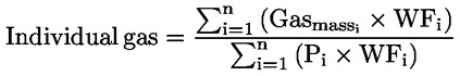
Table 26 — Emissions [g/h] and weighting factors according to different test modes
|
Mode
|
|
1
|
2
|
3
|
4
|
5
|
6
|
|
HCmass
|
g/h
|
25,666
|
25,993
|
21,607
|
21,850
|
34,074
|
48,963
|
|
NOxmass
|
g/h
|
67,168
|
38,721
|
19,012
|
4,621
|
2,319
|
0,811
|
|
COmass
|
g/h
|
2 188,001
|
2 068,760
|
1 510,187
|
1 424,792
|
1 853,109
|
975,435
|
|
CO2mass
|
g/h
|
9 354,488
|
7 295,794
|
5 717,531
|
3 973,503
|
2 756,113
|
1 430,229
|
|
Power Pi
|
kW
|
13,15
|
9,81
|
6,52
|
3,25
|
1,28
|
0
|
|
Weighting factors WFI
|
—
|
0,090
|
0,200
|
0,290
|
0,300
|
0,070
|
0,050
|


Appendix 4
1. COMPLIANCE WITH EMISSION STANDARDS
This Appendix shall apply to SI engines stage 2 only.
|
1.1.
|
The exhaust emission standards for stage 2 engines in Annex I (4.2) apply to the emissions of the engines for their emission durability period EDP as determined in accordance with this Appendix.
|
|
1.2.
|
For all stage 2 engines, if, when properly tested according to the procedures in this Directive, all test engines representing an engine family have emissions which, when adjusted by multiplication by the deterioration factor (DF) laid down in this Appendix, are less than or equal to each stage 2 emission standard (family emission limit (FEL), where applicable) for a given engine class, that family shall be considered to comply with the emission standards for that engine class. If any test engine representing an engine family has emissions which, when adjusted by multiplication by the deterioration factor laid down in this Appendix, are greater than any single emission standard (FEL, where applicable) for a given engine class, that family shall be considered not to comply with the emission standards for that engine class.
|
|
1.3.
|
Small volume engine manufacturers may, optionally, take deterioration factors for HC+NOx and CO from table 1 or 2 in this section, or they may calculate deterioration factors for HC + NOx and CO according to the process described in section 1.3.1. For technologies not covered by tables 1 and 2 in this section, the manufacturer must use the process described in section 1.4 in this Appendix.
Table 1: Hand-held engine HC + NOx and CO assigned deterioration factors for small volume manufacturer
|
Engine class
|
Two-stroke engines
|
Four-stroke engines
|
Engines with after treatment
|
|
HC + NOx
|
CO
|
HC + NOx
|
CO
|
|
SH:1
|
1,1
|
1,1
|
1,5
|
1,1
|
DFs must be calculated using the formula in section 1.3.1
|
|
SH:2
|
1,1
|
1,1
|
1,5
|
1,1
|
|
SH:3
|
1,1
|
1,1
|
1,5
|
1,1
|
Table 2: Non-hand-held engine HC + NOx and CO assigned deterioration factors for small volume manufacturers
|
Engine Class
|
Side Valve Engines
|
Overhead Valve Engines
|
Engines with after treatment
|
|
HC + NOx
|
CO
|
HC + NOx
|
CO
|
|
SN:1
|
2,1
|
1,1
|
1,5
|
1,1
|
DFs must be calculated using the formula in section 1.3.1
|
|
SN:2
|
2,1
|
1,1
|
1,5
|
1,1
|
|
SN:3
|
2,1
|
1,1
|
1,5
|
1,1
|
|
SN:4
|
1,6
|
1,1
|
1,4
|
1,1
|
|
1.3.1.
|
Formula for calculating deterioration factors for engines with after treatment:

where:
DF = deterioration factor
NE = new engine emission levels prior to the catalyst (g/kWh)
EDF = deterioration factor for engines without catalyst as shown in table 1
CC = amount converted at 0 hours in g/kWh
F = 0,8 for HC and 0,0 for NOx for all classes of engines
F = 0,8 for CO for all classes of engines
|
|
|
1.4.
|
Manufacturers shall obtain an assigned DF or calculate a DF, as appropriate, for each regulated pollutant for all stage 2 engine families. Such DFs shall be used for type approval and production line testing.
|
1.4.1.
|
For engines not using assigned DFs from tables 1 or 2 of this section, DFs shall be determined as follows:
|
1.4.1.1.
|
On at least one test engine representing the configuration chosen to be the most likely to exceed HC + NOx emission standards, (FELs where applicable), and constructed to be representative of production engines, conduct (full) test procedure emission testing as described in this Directive after the number of hours representing stabilised emissions.
|
|
1.4.1.2
|
If more than one engine is tested, average the results and round to the same number of decimal places contained in the applicable standard, expressed to one additional significant figure.
|
|
1.4.1.3
|
Conduct such emission testing again following ageing of the engine. The ageing procedure should be designed to allow the manufacturer to appropriately predict the in-use emission deterioration expected over the durability period of the engine, taking into account the type of wear and other deterioration mechanisms expected under typical consumer use which could affect emissions performance. If more than one engine is tested, average the results and round to the same number of decimal places contained in the applicable standard, expressed to one additional significant figure.
|
|
1.4.1.4.
|
Divide the emissions at the end of the durability period (average emissions, if applicable) for each regulated pollutant by the stabilised emissions (average emissions, if applicable) and round to two significant figures. The resulting number shall be the DF, unless it is less than 1,00, in which case the DF shall be 1,0.
|
|
1.4.1.5.
|
At the manufacturer's option additional emission test points can be scheduled between the stabilised emission test point and the emission durability period. If intermediate tests are scheduled, the test points must be evenly spaced over the EDP (plus or minus two hours) and one such test point shall be at one half of full EDP (plus or minus two hours).
For each pollutant HC + NOx and CO, a straight line must be fitted to the data points treating the initial test as occurring at hour zero, and using the method of least-squares. The deterioration factor is the calculated emissions at the end of the durability period divided by the calculated emissions at zero hours.
|
|
1.4.1.6.
|
Calculated deterioration factors may cover families in addition to the one on which they were generated if the manufacturer submits a justification acceptable to the national type approval authority in advance of type approval that the affected engine families can be reasonably expected to have similar emission deterioration characteristic based on the design and technology used.
A non-exclusive list of design and technology groupings is given below:
— conventional two-stroke engines without after treatment system,
— conventional two-stroke engines with a ceramic catalyst of the same active material and loading, and the same number of cells per cm2,
— conventional two-stroke engines with a metallic catalyst of the same active material and loading, same substrate and the same number of cells per cm2,
— two-stroke engines provided with a stratified scavenging system,
— four-stroke engines with catalyst (defined as above) with same valve technology and identical lubrication system,
— four-stroke engines without catalyst with the same valve technology and identical lubrication system.
|
|
|
2. EMISSION DURABILITY PERIODS FOR STAGE 2 ENGINES
|
2.1.
|
Manufacturers shall declare the applicable EDP category for each engine family at the time of type approval. Such category shall be the category which most closely approximates the expected useful lives of the equipment into which the engines are expected to be installed as determined by the engine manufacturer. Manufacturers shall retain data appropriate to support their choice of EDP category for each engine family. Such data shall be supplied to the approval authority upon request.
|
2.1.1.
|
For hand-held engines: manufacturers shall select an EDP category from table 1.
Table 1: EDP categories for hand-held engines (hours)
|
Category
|
1
|
2
|
3
|
|
Class SH:1
|
50
|
125
|
300
|
|
Class SH:2
|
50
|
125
|
300
|
|
Class SH:3
|
50
|
125
|
300
|
|
|
2.1.2.
|
For non-hand-held engines: manufacturers shall select an EDP category from table 2.
Table 2: EDP categories for non-hand-held engines (hours)
|
Category
|
1
|
2
|
3
|
|
Class SN:1
|
50
|
125
|
300
|
|
Class SN:2
|
125
|
250
|
500
|
|
Class SN:3
|
125
|
250
|
500
|
|
Class SN:4
|
250
|
500
|
1 000
|
|
|
2.1.3.
|
The manufacturer must satisfy the approval authority that the declared useful life is appropriate. Data to support a manufacturer's choice of EDP category, for a given engine family, may include but are not limited to:
— surveys of the life spans of the equipment in which the subject engines are installed,
— engineering evaluations of field aged engines to ascertain when engine performance deteriorates to the point where usefulness and/or reliability is impacted to a degree sufficient to necessitate overhaul or replacement,
— warranty statements and warranty periods,
— marketing materials regarding engine life,
— failure reports from engine customers, and
— engineering evaluations of the durability, in hours, of specific engine technologies, engine materials or engine designs.
|
|
▼B
ANNEX
►M2
V ◄
▼M3
TECHNICAL CHARACTERISTICS OF REFERENCE FUEL PRESCRIBED FOR APPROVAL TESTS AND TO VERIFY CONFORMITY OF PRODUCTION
NON-ROAD MOBILE MACHINERY REFERENCE FUEL FOR CI ENGINES TYPE APPROVED TO MEET STAGE I and II LIMIT VALUES AND FOR ENGINES TO BE USED IN INLAND WATERWAY VESSELS
▼B
Note: Key properties for engine performance/exhaust emissions are highlighted.
|
|
Limits and units (2)
|
Test method
|
|
Cetane number (4)
|
minimum 45 (7)
maximum 50
|
ISO 5165
|
|
Density at 15 oC
|
minimum 835 kg/m3
maximum 845 kg/m3 (10)
|
ISO 3675, ASTM D 4052
|
|
Distillation (3)
— 95 % point
|
Maximum 370 oC
|
ISO 3405
|
|
Viscosity at 40 oC
|
Minimum 2,5 mm2/s
Maximum 3,5 mm2/s
|
ISO 3104
|
|
Sulphur content
|
Minimum 0,1 % mass (9)
Maximum 0,2 % mass (8)
|
ISO 8754, EN 24260
|
|
Flash point
|
Minimum 55 oC
|
ISO 2719
|
|
CFPP
|
Minimum —
Maximum + 5 oC
|
EN 116
|
|
Copper corrosion
|
Maximum 1
|
ISO 2160
|
|
Conradson carbon residue (10 % DR)
|
Maximum 0,3 % mass
|
ISO 10370
|
|
Ash content
|
Maximum 0,01 % mass
|
ASTM D 482 (12)
|
|
Water content
|
Maximum 0,05 % mass
|
ASTM D 95, D 1744
|
|
Neutralization (strong acid) number
|
►M1
►M2
Maximum ◄ 0,20 mg KOH/g ◄
|
|
|
Oxidation stability (5)
|
Maximum 2,5 mg/100 ml
|
ASTM D 2274
|
|
Additives (6)
|
|
|
|
Note 1:If it is required to calculate thermal efficiency of an engine or vehicle, the calorific value of the fuel can be calculated from:

where:
d is the density at 288 K (15 oC)
x is the proportion by mass of water (%/100)
y is the proportion by mass of ash (%/100)
s is the proportion by mass of sulphur (%/100).
Note 2:The values quoted in the specification are ‘true values’. In establishment of their limit values the terms of ASTM D 3244 ‘Defining a basis for petroleum produce quality disputes’ have been applied and in fixing a minimum value, a minimum difference of 2R above zero has been taken into account; in fixing a maximum and minimum value, the minimum difference is 4R (R = reproducibility).
Notwithstanding this measure, which is necessary for statistical reasons, the manufacturer of fuel should nevertheless aim at a zero value where the stipulated maximum value is 2R and the mean value in the case of quotations of maximum and minimum limits. Should it be necessary to clarify the question as to whether a fuel meets the requirements of the specifications, the terms of ASTM D 3244 should be applied.
Note 3:The figures quoted show the evaporated quantities (percentage recovered + percentage loss).
Note 4:The range of cetane is not in accordance with the requirement of a minimum range of 4R. Hovever, in cases of dispute between fuel supplier and fuel user, the terms in ASTM D 3244 can be used to resolve such disputes provided replicate measurements, of sufficient number to achieve the necessary precision, are made in preference to single determinations.
Note 5:Even though oxidation stability is controlled, it is likely that shelf life will be limited. Advice should be sought from the supplier as to storage conditions and life.
Note 6:This fuel should be based straight run and cracked hydrocarbon distillate components only; desulphurization is allowed. It must not contain any metallic additives or cetane improver additives.
Note 7:Lower values are permitted, in which case the cetane number of the reference fuel used is to be reported.
Note 8:Higher values are permitted, in which case the sulphur content of the reference fuel used is to be reported.
Note 9:To be kept under constant review in the light of trends in the markets.
►M1
For the purpose of the initial approval of an engine with no exhaust gas after treatment on the request of the applicant a 0,05 % mass nominal sulphur level (minimum 0,03 % mass) is permissible, in which case the measured particulate level must be corrected upward to the average value that is nominally specified for fuel sulphur content (0,15 % mass) per the equation below:
◄

where:
PTadj = adjusted PT value (g/kWh)
PT = measured weighted specific emission value for particulate emission (g/kWh)
SFC = weighted specific fuel consumption (g/kWh) calculated according to the formula as below
NSLF = average of the nominal specification of sulphur content mass fraction (i.e. 0,15 %/100)
FSF = fuel sulphur content mass fraction (%/100)
Equation for the calculation of the weighted specific fuel consumption:
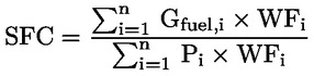
where:
Pi = Pm,i + PAE,i
For the purpose of conformity of production assessments in accordance with section 5.3.2. of Annex I, the requirements must be met using reference fuel with a sulphur content which complies with the minimum/maximum level of 0,1/0,2 % mass.
Note 10:Higher values are permitted up to 855 kg/m3, in which case the density of the reference fuel used is to be reported. For the purpose of conformity of production assessments in accordance with section 5.3.2. of Annex I, the requirements must be met using reference fuel which complies with the minimum/maximum level of 835/845 kg/m3.
Note 11:All fuel characteristics and limit values are to be kept under review in light of trends in the markets.
Note 12:To be replaced by EN/ISO 6245 with effect of the date of implementation.
|
▼M3
NON-ROAD MOBILE MACHINERY REFERENCE FUEL FOR CI ENGINES TYPE APPROVED TO MEET STAGE IIIA LIMIT VALUES.
|
Parameter
|
Unit
|
Limits (1)
|
Test method
|
|
Minimum
|
Maximum
|
|
Cetane number (2)
|
|
52
|
54,0
|
EN-ISO 5165
|
|
Density at 15 °C
|
kg/m3
|
833
|
837
|
EN-ISO 3675
|
|
Distillation:
|
|
|
|
|
|
50 % point
|
°C
|
245
|
—
|
EN-ISO 3405
|
|
95 % point
|
°C
|
345
|
350
|
EN-ISO 3405
|
|
— Final boiling point
|
°C
|
—
|
370
|
EN-ISO 3405
|
|
Flash point
|
°C
|
55
|
—
|
EN 22719
|
|
CFPP
|
°C
|
—
|
–5
|
EN 116
|
|
Viscosity at 40 °C
|
mm2/s
|
2,5
|
3,5
|
EN-ISO 3104
|
|
Polycyclic aromatic hydrocarbons
|
% m/m
|
3,0
|
6,0
|
IP 391
|
|
Sulphur content (3)
|
mg/kg
|
—
|
300
|
ASTM D 5453
|
|
Copper corrosion
|
|
—
|
class 1
|
EN-ISO 2160
|
|
Conradson carbon residue (10 % DR)
|
% m/m
|
—
|
0,2
|
EN-ISO 10370
|
|
Ash content
|
% m/m
|
—
|
0,01
|
EN-ISO 6245
|
|
Water content
|
% m/m
|
—
|
0,05
|
EN-ISO 12937
|
|
Neutralisation (strong acid) number
|
mg KOH/g
|
—
|
0,02
|
ASTM D 974
|
|
Oxidation stability (4)
|
mg/ml
|
—
|
0,025
|
EN-ISO 12205
|
|
(1) The values quoted in the specifications are ‘true values’. In establishment of their limit values the terms of ISO 4259 ‘Petroleum products – Determination and application of precision data in relation to methods of test’ have been applied and in fixing a minimum value, a minimum difference of 2R above zero has been taken into account; in fixing a maximum and minimum value, the minimum difference is 4R (R = reproducibility).
(2) The range for cetane number is not in accordance with the requirements of a minimum range of 4R. However, in the case of a dispute between fuel supplier and fuel user, the terms of ISO 4259 may be used to resolve such disputes provided replicate measurements, of sufficient number to archive the necessary precision, are made in preference to single determinations.
(3) The actual sulphur content of the fuel used for the test shall be reported.
(4) Even though oxidation stability is controlled, it is likely that shelf life will be limited. Advice should be sought from the supplier as to storage conditions and life.
|
NON-ROAD MOBILE MACHINERY REFERENCE FUEL FOR CI ENGINES TYPE APPROVED TO MEET STAGE IIIB AND IV LIMIT VALUES.
|
Parameter
|
Unit
|
Limits (1)
|
Test method
|
|
Minimum
|
Maximum
|
|
Cetane number (2)
|
|
|
54,0
|
EN-ISO 5165
|
|
▼M6
|
|
Density at 15 °C
|
kg/m3
|
833
|
865
|
EN-ISO 3675
|
|
▼C1
|
|
Distillation:
|
|
|
|
|
|
50 % point
|
°C
|
245
|
—
|
EN-ISO 3405
|
|
95 % point
|
°C
|
345
|
350
|
EN-ISO 3405
|
|
— Final boiling point
|
°C
|
—
|
370
|
EN-ISO 3405
|
|
Flash point
|
°C
|
55
|
—
|
EN 22719
|
|
CFPP
|
°C
|
—
|
–5
|
EN 116
|
|
Viscosity at 40 °C
|
mm2/s
|
2,3
|
3,3
|
EN-ISO 3104
|
|
Polycyclic aromatic hydrocarbons
|
% m/m
|
3,0
|
6,0
|
IP 391
|
|
Sulphur content (3)
|
mg/kg
|
—
|
10
|
ASTM D 5453
|
|
Copper corrosion
|
|
—
|
class 1
|
EN-ISO 2160
|
|
Conradson carbon residue (10 % DR)
|
% m/m
|
—
|
0,2
|
EN-ISO 10370
|
|
Ash content
|
% m/m
|
—
|
0,01
|
EN-ISO 6245
|
|
Water content
|
% m/m
|
—
|
0,02
|
EN-ISO 12937
|
|
Neutralisation (strong acid) number
|
mg KOH/g
|
—
|
0,02
|
ASTM D 974
|
|
Oxidation stability (4)
|
mg/ml
|
—
|
0,025
|
EN-ISO 12205
|
|
Lubricity (HFRR wear scar diameter at 60 °C)
|
μm
|
—
|
400
|
CEC F-06-A-96
|
|
FAME
|
prohibited
|
|
(1) The values quoted in the specifications are ’true values’. In establishment of their limit values the terms of ISO 4259 ‘Petroleum products – Determination and application of precision data in relation to methods of test’ have been applied and in fixing a minimum value, a minimum difference of 2R above zero has been taken into account; in fixing a maximum and minimum value, the minimum difference is 4R (R = reproducibility).
(2) The range for cetane number is not in accordance with the requirements of a minimum range of 4R. However, in the case of a dispute between fuel supplier and fuel user, the terms of ISO 4259 may be used to resolve such disputes provided replicate measurements, of sufficient number to archive the necessary precision, are made in preference to single determinations.
(3) The actual sulphur content of the fuel used for the Type I test shall be reported.
(4) Even though oxidation stability is controlled, it is likely that shelf life will be limited. Advice should be sought from the supplier as to storage conditions and life.
|
▼M2
NON-ROAD MOBILE MACHINERY REFERENCE FUEL FOR SI ENGINES
Note: The fuel for two-stroke engines is a blend of lubricant oil and the petrol specified below. The fuel/oil mixture ratio must be the ratio which is recommended by the manufacturer as specified in Annex IV, section 2.7.
|
Parameter
|
Unit
|
Limits (1)
|
Test method
|
Publication
|
|
Minimum
|
Maximum
|
|
Research octane number, RON
|
|
95,0
|
—
|
EN 25164
|
1 993
|
|
Motor octane number, MON
|
|
85,0
|
—
|
EN 25163
|
1 993
|
|
Density at 15 oC
|
kg/m3
|
748
|
762
|
ISO 3675
|
1 995
|
|
Reid vapour pressure
|
kPa
|
56,0
|
60,0
|
EN 12
|
1 993
|
|
Distillation
|
|
|
—
|
|
|
|
Initial boiling point
|
oC
|
24
|
40
|
EN-ISO 3405
|
1 988
|
|
— Evaporated at 100 oC
|
% v/v
|
49,0
|
57,0
|
EN-ISO 3405
|
1 988
|
|
— Evaporated at 150 oC
|
% v/v
|
81,0
|
87,0
|
EN-ISO 3405
|
1 988
|
|
— Final boiling point
|
oC
|
190
|
215
|
EN-ISO 3405
|
1 988
|
|
Residue
|
%
|
—
|
2
|
EN-ISO 3405
|
1 988
|
|
Hydrocarbon analysis
|
—
|
|
|
|
—
|
|
— Olefins
|
% v/v
|
—
|
10
|
ASTM D 1319
|
1 995
|
|
— Aromatics
|
% v/v
|
28,0
|
40,0
|
ASTM D 1319
|
1 995
|
|
— Benzene
|
% v/v
|
—
|
1,0
|
EN 12177
|
1 998
|
|
— Saturates
|
% v/v
|
—
|
balance
|
ASTM D 1319
|
1 995
|
|
Carbon/hydrogen ratio
|
|
report
|
report
|
|
|
|
Oxidation stability (2)
|
min.
|
480
|
—
|
EN-ISO 7536
|
1 996
|
|
Oxygen content
|
% m/m
|
—
|
2,3
|
EN 1601
|
1 997
|
|
Existent gum
|
mg/ml
|
—
|
0,04
|
EN-ISO 6246
|
1 997
|
|
Sulphur content
|
mg/kg
|
—
|
100
|
EN-ISO 14596
|
1 998
|
|
Copper corrosion at 50 oC
|
|
—
|
1
|
EN-ISO 2160
|
1 995
|
|
Lead content
|
g/l
|
—
|
0,005
|
EN 237
|
1 996
|
|
Phosphorus content
|
g/l
|
—
|
0,0013
|
ASTM D 3231
|
1 994
|
Note 1: The values quoted in the specification are ‘true values’. In establishment of their limit values the terms of ISO 4259 ‘Petroleum products — Determination and application of precision data in relation to methods of test’ have been applied and in fixing a minimum value, a minimum difference of 2R above zero has been taken into account; in fixing a maximum and minimum value, the minimum difference is 4R (R = reproducibility). Notwithstanding this measure, which is necessary for statistical reasons, the manufacturer of fuels should nevertheless aim at a zero value where the stipulated maximum value is 2R and at the mean value in the case of quotations of maximum and minimum limits. Should it be necessary to clarify the question as to whether a fuel meets the requirements of the specifications, the terms of ISO 4259 should be applied.
Note 2: The fuel may contain oxidation inhibitors and metal deactivators normally used to stabilise refinery gasoline streams, but detergent/dispersive additives and solvent oils must not be added.
▼M3
ANNEX VI
ANALYTICAL AND SAMPLING SYSTEM
1. GASEOUS AND PARTICULATE SAMPLING SYSTEMS
|
Figure number
|
Description
|
|
2
|
Exhaust gas analysis system for raw exhaust
|
|
3
|
Exhaust gas analysis system for dilute exhaust
|
|
4
|
Partial flow, isokinetic flow, suction blower control, fractional sampling
|
|
5
|
Partial flow, isokinetic flow, pressure blower control, fractional sampling
|
|
6
|
Partial flow, CO2 or NOx control, fractional sampling
|
|
7
|
Partial flow, CO2 or carbon balance, total sampling
|
|
8
|
Partial flow, single venturi and concentration measurement, fractional sampling
|
|
9
|
Partial flow, twin venturi or orifice and concentration measurement, fractional sampling
|
|
10
|
Partial flow, multiple tube splitting and concentration measurement, fractional sampling
|
|
11
|
Partial flow, flow control, total sampling
|
|
12
|
Partial flow, flow control, fractional sampling
|
|
13
|
Full flow, positive displacement pump or critical flow venturi, fractional sampling
|
|
14
|
Particulate sampling system
|
|
15
|
Dilution system for full flow system
|
1.1. Determination of the gaseous emissions
Section 1.1.1 and Figures 2 and 3 contain detailed descriptions of the recommended sampling and analysing systems. Since various configurations can produce equivalent results, exact conformance with these figures is not required. Additional components such as instruments, valves, solenoids, pumps and switches may be used to provide additional information and coordinate the functions of the component systems. Other components which are not needed to maintain the accuracy on some systems, may be excluded if their exclusion is based upon good engineering judgement.
1.1.1. Gaseous exhaust components CO, CO2, HC, NOx
An analytical system for the determination of the gaseous emissions in the raw or diluted exhaust gas is described based on the use of:
— HFID analyser for the measurement of hydrocarbons,
— NDIR analysers for the measurement of carbon monoxide and carbon dioxide,
— HCLD or equivalent analyser for the measurement of nitrogen oxide.
For the raw exhaust gas (Figure 2), the sample for all components may be taken with one sampling probe or with two sampling probes located in close proximity and internally split to the different analysers. Care must be taken that no condensation of exhaust components (including water and sulphuric acid) occurs at any point of the analytical system.
For the diluted exhaust gas (Figure 3), the sample for the hydrocarbons shall be taken with another sampling probe than the sample for the other components. Care must be taken that no condensation of exhaust components (including water and sulphuric acid) occurs at any point of the analytical system.
Figure 2
Flow diagram of exhaust gas analysis system for CO, NOx and HC

Figure 3
Flow diagram of dilute exhaust gas analysis system for CO, CO2, NOx and HC

Descriptions — Figures 2 and 3
General statement:
All components in the sampling gas path must be maintained at the temperature specified for the respective systems.
— SP1 raw exhaust gas sampling probe (Figure 2 only)
A stainless steel straight closed and multihole probe is recommended. The inside diameter shall not be greater than the inside diameter of the sampling line. The wall thickness of the probe shall not be greater than 1 mm. There shall be a minimum of three holes in three different radial planes sized to sample approximately the same flow. The probe must extend across at least 80 % of the diameter of the exhaust pipe.
— SP2 dilute exhaust gas HC sampling probe (Figure 3 only)
The probe shall:
— be defined as the first 254 mm to 762 mm of the hydrocarbon sampling line (HSL3),
— have a 5 mm minimum inside diameter,
— be installed in the dilution tunnel DT (section 1.2.1.2) at a point where the dilution air and exhaust gas are well mixed (i.e. approximately 10 tunnel diameters downstream of the point where the exhaust enters the dilution tunnel),
— be sufficiently distant (radially) from other probes and the tunnel wall so as to be free from the influence of any wakes or eddies,
— be heated so as to increase the gas stream temperature to 463 K (190 °C) ± 10 K at the exit of the probe.
— SP3 dilute exhaust gas CO, CO2, NOx sampling probe (Figure 3 only)
The probe shall:
— be in the same plane as SP2,
— be sufficiently distant (radially) from other probes and the tunnel wall so as to be free from the influence of any wakes or eddies,
— be heated and insulated over its entire length to a minimum temperature of 328 K (55 °C) to prevent water condensation.
— HSL1 heated sampling line
The sampling line provides gas sampling from a single probe to the split point(s) and the HC analyser.
The sampling line shall:
— have a 5 mm minimum and a 13,5 mm maximum inside diameter,
— be made of stainless steel or PTFE,
— maintain a wall temperature of 463 (190 °C) ± 10 K as measured at every separately controlled heated section, if the temperature of the exhaust gas at the sampling probe is equal or below 463 K (190 °C),
— maintain a wall temperature greater than 453 K (180 °C) if the temperature of the exhaust gas at the sampling probe is above 463 K (190 °C),
— maintain a gas temperature of 463 K (190 °C) ± 10 K immediately before the heated filter (F2) and the HFID.
— HSL2 heated NOx sampling line
The sampling line shall:
— maintain a wall temperature of 328 to 473 K (55 to 200 °C) up to the converter when using a cooling bath, and up to the analyser when a cooling bath is not used,
— be made of stainless steel or PTFE.
Since the sampling line need only be heated to prevent condensation of water and sulphuric acid, the sampling line temperature will depend on the sulphur content of the fuel.
— SL sampling line for CO (CO2)
The line shall be made of PTFE or stainless steel. It may be heated or unheated.
— BK background bag (optional; Figure 3 only)
For the measurement of the background concentrations.
— BG sample bag (optional; Figure 3 CO and CO2 only)
For the measurement of the sample concentrations.
— F1 heated pre-filter (optional)
The temperature shall be the same as HSL1.
— F2 heated filter
The filter shall extract any solid particles from the gas sample prior to the analyser. The temperature shall be the same as HSL1. The filter shall be changed as needed.
— P heated sampling pump
The pump shall be heated to the temperature of HSL1.
— HC
Heated flame ionization detector (HFID) for the determination of the hydrocarbons. The temperature shall be kept at 453 to 473 K (180 to 200 °C).
— CO, CO2
NDIR analysers for the determination of carbon monoxide and carbon dioxide.
— NO2
(H)CLD analyser for the determination of the oxides of nitrogen. If a HCLD is used it shall be kept at a temperature of 328 to 473 K (55 to 200 °C).
— C converter
A converter shall be used for the catalytic reduction of NO2 to NO prior to analysis in the CLD or HCLD.
— B cooling bath
To cool and condense water from the exhaust sample. The bath shall be maintained at a temperature of 273 to 277 K (0 to 4 °C) by ice or refrigeration. It is optional if the analyser is free from water vapour interference as determined in Annex III, Appendix 2, sections 1.9.1 and 1.9.2.
Chemical dryers are not allowed for removing water from the sample.
— T1, T2, T3 temperature sensor
To monitor the temperature of the gas stream.
— T4 temperature sensor
Temperature of the NO2-NO converter.
— T5 temperature sensor
To monitor the temperature of the cooling bath.
— G1, G2, G3 pressure gauge
To measure the pressure in the sampling lines.
— R1, R2 pressure regulator
To control the pressure of the air and the fuel, respectively, for the HFID.
— R3, R4, R5 pressure regulator
To control the pressure in the sampling lines and the flow to the analysers.
— FL1, FL2, FL3 flow meter
To monitor the sample bypass flow.
— FL4 to FL7 flow meter (optional)
To monitor the flow rate through the analysers.
— V1 to V6 selector valve
Suitable valving for selecting sample, span gas or zero gas flow to the analyser.
— V7, V8 solenoid valve
To bypass the NO2-NO converter.
— V9 needle valve
To balance the flow through the NO2-NO converter and the bypass.
— V10, V11 needle valve
To regulate the flows to the analysers.
— V12, V13 toggle valve
To drain the condensate from the bath B.
— V14 selector valve
Selecting the sample or background bag.
1.2. Determination of the particulates
Sections 1.2.1 and 1.2.2 and Figures 4 to 15 contain detailed descriptions of the recommended dilution and sampling systems. Since various configurations can produce equivalent results, exact conformance with these figures is not required. Additional components such as instruments, valve, solenoids, pumps and switches may be used to provide additional information and coordinate the functions of the component systems. Other components which are not needed to maintain the accuracy on some systems, may be excluded if their exclusion is based on good engineering judgement.
1.2.1. Dilution system
1.2.1.1. Partial flow dilution system (Figures 4 to 12) (
30
)
A dilution system is described based on the dilution of a part of the exhaust stream. Splitting of the exhaust stream and the following dilution process may be done by different dilution system types. For subsequent collection of the particulates, the entire dilute exhaust gas or only a portion of the dilute exhaust gas may be passed to the particulate sampling system (section 1.2.2, Figure 14). The first method is referred to as total sampling type, the second method as fractional sampling type.
The calculation of the dilution ratio depends on the type of system used.
The following types are recommended:
— isokinetic systems (Figures 4 and 5)
With these systems, the flow into the transfer tube is matched to the bulk exhaust flow in terms of gas velocity and/or pressure, thus requiring an undisturbed and uniform exhaust flow at the sampling probe. This is usually achieved by using a resonator and a straight approach tube upstream of the sampling point. The split ratio is then calculated from easily measurable values like tube diameters. It should be noted that isokinesis is only used for matching the flow conditions and not for matching the size distribution. The latter is typically not necessary, as the particles are sufficiently small as to follow the fluid streamlines,
— flow controlled systems with concentration measurement (Figures 6 to 10)
With these systems, a sample is taken from the bulk exhaust stream by adjusting the dilution air flow and the total dilution exhaust flow. The dilution ratio is determined from the concentrations of tracer gases, such as CO2 or NOx, naturally occurring in the engine exhaust. The concentrations in the dilution exhaust gas and in the dilution air are measured, whereas the concentration in the raw exhaust gas can be either measured directly or determined from fuel flow and the carbon balance equation, if the fuel composition is known. The systems may be controlled by the calculated dilution ratio (Figures 6 and 7) or by the flow into the transfer tube (Figures 8, 9 and 10),
— flow controlled systems with flow measurement (Figures 11 and 12)
With these systems, a sample is taken from the bulk exhaust stream by setting the dilution air flow and the total dilution exhaust flow. The dilution ratio is determined from the difference of the two flow rates. Accurate calibration of the flow meters relative to one another is required, since the relative magnitude of the two flow rates can lead to significant errors at higher dilution ratios. Flow control is very straightforward by keeping the dilute exhaust flow rate constant and varying the dilution air flow rate, if needed.
In order to realise the advantages of the partial flow dilution systems, attention must be paid to avoiding the potential problems of loss of particulates in the transfer tube, ensuring that a representative sample is taken from the engine exhaust, and determination of the split ratio.
The systems described pay attention to these critical areas.
Figure 4
Partial flow dilution system with isokinetic probe and fractional sampling (SB control)

Raw exhaust gas is transferred from the exhaust pipe to EP to the dilution tunnel DT through the transfer tube TT by the isokinetic sampling probe ISP. The differential pressure of the exhaust gas between exhaust pipe and inlet to the probe is measured with the pressure transducer DPT. This signal is transmitted to the flow controller FC1 that controls the suction blower SB to maintain a differential pressure of zero at the tip of the probe. Under these conditions, exhaust gas velocities in EP and ISP are identical, and the flow through ISP and TT is a constant fraction (split) of the exhaust gas flow. The split ratio is determined from the cross sectional areas of EP and ISP. The dilution air flow rate is measured with the flow measurement device FM1. The dilution ratio is calculated from the dilution air flow rate and the split ratio.
Figure 5
Partial flow dilution system with isokinetic probe and fractional sampling (PB control)

Raw exhaust gas is transferred from the exhaust pipe EP to the dilution tunnel DT through the transfer tube TT by the isokinetic sampling probe ISP. The differential pressure of the exhaust gas between exhaust pipe and inlet to the probe is measured with the pressure transducer DPT. This signal is transmitted to the flow controller FC1 that controls the pressure blower PB to maintain a differential pressure of zero at the tip of the probe. This is done by taking a small fraction of the dilution air whose flow rate has already been measured with the flow measurement device FM1, and feeding it to TT by means of a pneumatic orifice. Under these conditions, exhaust gas velocities in EP and ISP are identical, and the flow through ISP and TT is a constant fraction (split) of the exhaust gas flow. The split ratio is determined from the cross sectional areas of EP and ISP. The dilution air is sucked through DT by the suction blower SB, and the flow rate is measured with FM1 at the inlet to DT. The dilution ratio is calculated from the dilution air flow rate and the split ratio.
Figure 6
Partial flow dilution system with CO2 or NOx concentration measurement and fractional sampling

Raw exhaust gas is transferred from the exhaust pipe EP to the dilution tunnel DT through the sampling probe SP and the transfer tube TT. The concentrations of a tracer gas (CO2 or NOx) are measured in the raw and diluted exhaust gas as well as in the dilution air with the exhaust gas analyser(s) EGA. These signals are transmitted to the flow controller FC2 that controls either the pressure blower PB or the suction blower SB to maintain the desired exhaust split and dilution ratio in DT. The dilution ratio is calculated from the tracer gas concentrations in the raw exhaust gas, the diluted exhaust gas, and the dilution air.
Figure 7
Partial flow dilution system with CO2 concentration measurement, carbon balance and total sampling

Raw exhaust gas is transferred from the exhaust pipe EP to the dilution tunnel DT through the sampling probe SP and the transfer tube TT. The CO2 concentrations are measured in the diluted exhaust gas and in the dilution air with the exhaust gas analyser(s) EGA. The CO2 and fuel flow GFUEL signals are transmitted either to the flow controller FC2, or to the flow controller FC3 of the particulate sampling system (Figure 14). FC2 controls the pressure blower PB, while FC3 controls the particulate sampling system (Figure 14), thereby adjusting the flows into and out of the system so as to maintain the desired exhaust split and dilution ratio in DT. The dilution ratio is calculated from the CO2 concentrations and GFUEL using the carbon balance assumption.
Figure 8
Partial flow dilution system with single venturi, concentration measurement and fractional sampling

Raw exhaust gas is transferred from the exhaust pipe EP to the dilution tunnel DT through the sampling probe SP and the transfer tube TT due to the negative pressure created by the venturi VN in DT. The gas flow rate through TT depends on the momentum exchange at the venturi zone, and is therefore affected by the absolute temperature of the gas at the exit of TT. Consequently, the exhaust split for a given tunnel flow rate is not constant, and the dilution ratio at low load is slightly lower than at high load. The tracer gas concentrations (CO2 or NOx) are measured in the raw exhaust gas, the diluted exhaust gas, and the dilution air with the exhaust gas analyser(s) EGA, and the dilution ratio is calculated from the values so measured.
Figure 9
Partial flow dilution system twin venturi or twin orifice, concentration measurement and fractional sampling

Raw exhaust gas is transferred from the exhaust pipe EP to the dilution tunnel DT through the sampling probe SP and the transfer tube TT by a flow divider that contains a set of orifices or venturis. The first one (FD1) is located in EP, the second one (FD2) in TT. Additionally, two pressure control valves (PCV1 and PCV2) are necessary to maintain a constant exhaust split by controlling the backpressure in EP and the pressure in DT. PCV1 is located downstream of SP in EP, PCV2 between the pressure blower PB and DT. The tracer gas concentrations (CO2 or NOx) are measured in the raw exhaust gas, the diluted exhaust gas, and the dilution air with the exhaust gas analyser(s) EGA. They are necessary for checking the exhaust split, and may be used to adjust PCV1 and PCV2 for precise split control. The dilution ratio is calculated from the tracer gas concentrations.
Figure 10
Partial flow dilution system with multiple tube splitting, concentration measurement and fractional sampling

Raw exhaust gas is transferred from the exhaust pipe EP to the dilution tunnel DT through the transfer tube TT by the flow divider FD3 that consists of a number of tubes of the same dimensions (same diameter, length and bed radius) installed in EP. The exhaust gas through one of these tubes is lead to DT, and the exhaust gas through the rest of the tubes is passed through the damping chamber DC. Thus, the exhaust split is determined by the total number of tubes. A constant split control requires a differential pressure of zero between DC and the outlet of TT, which is measured with the differential pressure transducer DPT. A differential pressure of zero is achieved by injecting fresh air into DT at the outlet of TT. The tracer gas concentrations (CO2 or NOx) are measured in the raw exhaust gas, the diluted exhaust gas, and the dilution air with the exhaust gas analyser(s) EGA. They are necessary for checking the exhaust split and may be used to control the injection air flow rate for precise split control. The dilution ratio is calculated from the tracer gas concentrations.
Figure 11
Partial flow dilution system with flow control and total sampling

Raw exhaust gas is transferred from the exhaust pipe EP to the dilution tunnel DT through the sampling probe SP and the transfer tube TT. The total flow through the tunnel is adjusted with the flow controller FC3 and the sampling pump P of the particulate sampling system (Figure 16).
The dilution air flow is controlled by the flow controller FC2, which may use GEXH, GAIR or GFUEL as command signals, for the desired exhaust split. The sample flow into DT is the difference of the total flow and the dilution air flow. The dilution air flow rate is measured with flow measurement device FM1, the total flow rate with the flow measurement device FM3 of the particulate sampling system (Figure 14). The dilution ratio is calculated from these two flow rates.
Figure 12
Partial flow dilution system with flow control and fractional sampling
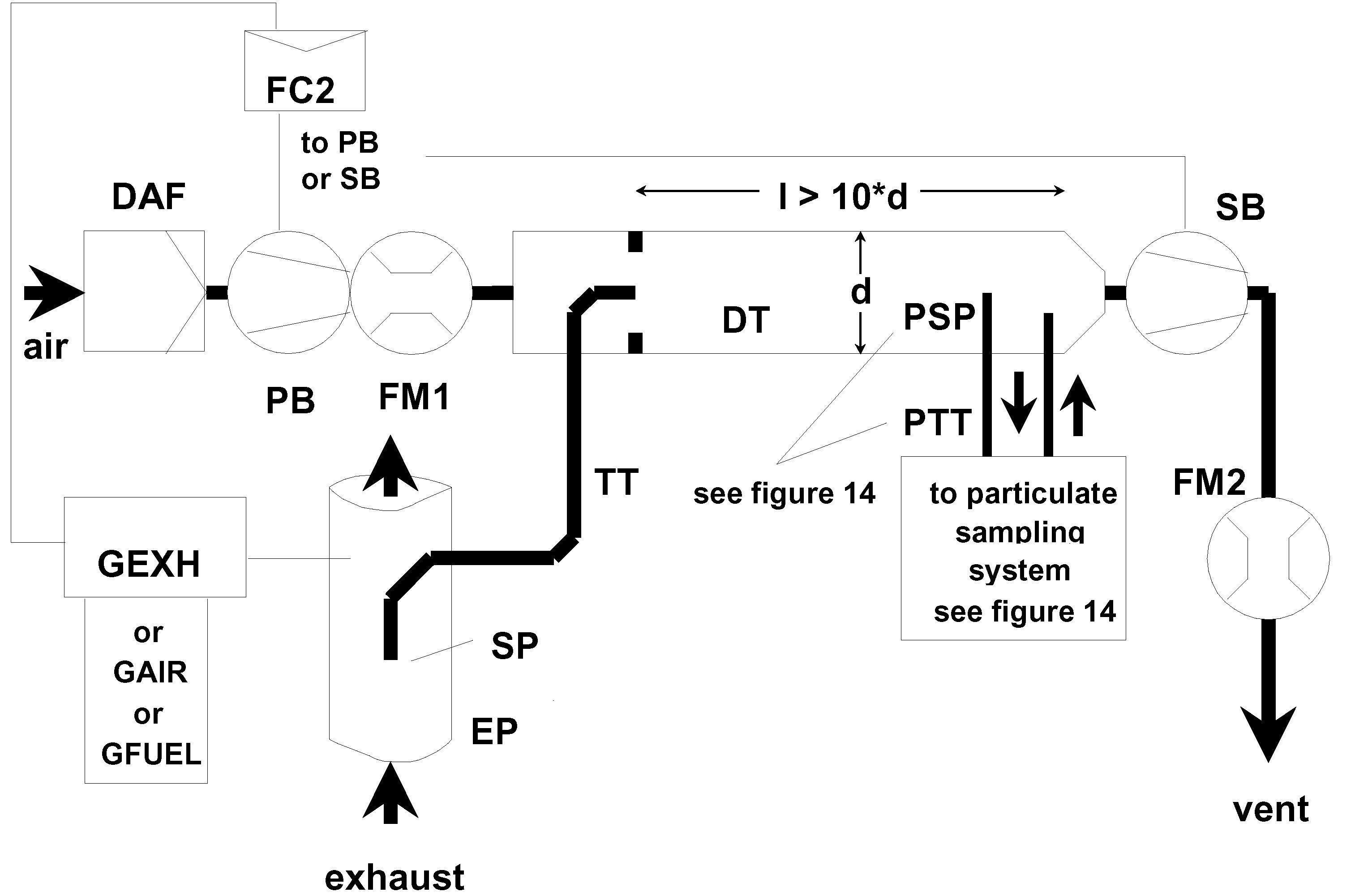
Raw exhaust gas is transferred from the exhaust pipe EP to the dilution tunnel DT through the sampling probe SP and the transfer tube TT. The exhaust split and the flow into DT is controlled by the flow controller FC2 that adjusts the flows (or speeds) of the pressure blower PB and the suction blower SB, accordingly. This is possible since the sample taken with the particulate sampling system is returned into DT. GGEXH, GAIR or GFUEL may be used as command signals for FC2. The dilution air flow rate is measured with the flow measurement device FM1, the total flow with the flow measurement device FM2. The dilution ratio is calculated from these two flow rates.
Description - Figures 4 to 12
— EP exhaust pipe
The exhaust pipe may be insulated. To reduce the thermal inertia of the exhaust pipe a thickness to diameter ratio of 0,015 or less is recommended. The use of flexible sections shall be limited to a length to diameter ratio of 12 or less. Bends will be minimised to reduce inertial deposition. If the system includes a test bed silencer, the silencer may also be insulated.
For an isokinetic system, the exhaust pipe must be free of elbows, bends and sudden diameter changes for at least six pipe diameters upstream and three pipe diameters downstream of the tip of the probe. The gas velocity at the sampling zone must be higher than 10 m/s except at idle mode. Pressure oscillations of the exhaust gas must not exceed ± 500 Pa on the average. Any steps to reduce pressure oscillations beyond using a chassis-type exhaust system (including silencer and after-treatment device) must not alter engine performance nor cause the deposition of particulates.
For systems without isokinetic probes, it is recommended to have a straight pipe of six pipe diameters upstream and three pipe diameters downstream of the tip of the probe.
— SP sampling probe (Figures 6 to 12)
The minimum inside diameter shall be 4 mm. The minimum diameter ratio between exhaust pipe and probe shall be four. The probe shall be an open tube facing upstream on the exhaust pipe centre-line, or a multiple hole probe as described under SP1 in section 1.1.1.
— ISP isokinetic sampling probe (Figures 4 and 5)
The isokinetic sampling probe must be installed facing upstream on the exhaust pipe centre-line where the flow conditions in section EP are met, and designed to provide a proportional sample of the raw exhaust gas. The minimum inside diameter shall be 12 mm.
A control system is necessary for isokinetic exhaust splitting by maintaining a differential pressure of zero between EP and ISP. Under these conditions exhaust gas velocities in EP and ISP are identical and the mass flow through ISP is a constant fraction of the exhaust gas flow. The ISP has to be connected to a differential pressure transducer. The control to provide a differential pressure of zero between EP and ISP is done with blower speed or flow controller.
— FD1, FD2 flow divider (Figure 9)
A set of venturis or orifices is installed in the exhaust pipe EP and in the transfer tube TT, respectively, to provide a proportional sample of the raw exhaust gas. A control system consisting of two pressure control valves PCV1 and PCV2 is necessary for proportional splitting by controlling the pressures in EP and DT.
— FD3 flow divider (Figure 10)
A set of tubes (multiple tube unit) is installed in the exhaust pipe EP to provide a proportional sample of the raw exhaust gas. One of the tubes feeds exhaust gas to the dilution tunnel DT, whereas the other tubes exit exhaust gas to a damping chamber DC. The tubes must have the same dimensions (same diameter, length, bend radius), so that the exhaust split depends on the total number of tubes. A control system is necessary for proportional splitting by maintaining a differential pressure of zero between the exit of the multiple tube unit into DC and the exit of TT. Under these conditions, exhaust gas velocities in EP and FD3 are proportional, and the flow TT is a constant fraction of the exhaust gas flow. The two points have to be connected to a differential pressure transducer DPT. The control to provide a differential pressure of zero is done with the flow controller FC1.
— EGA exhaust gas analyser (Figures 6 to 10)
CO2 or NOx analysers may be used (with carbon balance method CO2 only). The analysers shall be calibrated like the analysers for the measurement of the gaseous emissions. One or several analysers may be used to determine the concentration differences.
The accuracy of the measuring systems has to be such that the accuracy of GEDFW, i is within ± 4 %.
— TT transfer tube (Figures 4 to 12)
The particulate sample transfer tube shall be:
— as short as possible, but not more than 5 m in length,
— equal to or greater than the probe diameter, but not more than 25 mm in diameter,
— exiting on the centre-line of the dilution tunnel and pointing downstream.
If the tube is 1 metre or less in length, it is to be insulated with material with a maximum thermal conductivity of 0,05 W/(m · K) with a radial insulation thickness corresponding to the diameter of the probe. If the tube is longer than 1 metre, it must be insulated and heated to a minimum wall temperature of 523 K (250 °C).
Alternatively, the transfer tube wall temperatures required may be determined through standard heat transfer calculations.
— DPT differential pressure transducer (Figures 4, 5 and 10)
The differential pressure transducer shall have a range of ± 500 Pa or less.
— FC1 flow controller (Figures 4, 5 and 10)
For the isokinetic systems (Figures 4 and 5) a flow controller is necessary to maintain a differential pressure of zero between EP and ISP. The adjustment can be done by:
(a) controlling the speed or flow of the suction blower (SB) and keeping the speed of the pressure blower (PB) constant during each mode (Figure 4); or
(b) adjusting the suction blower (SB) to a constant mass flow of the diluted exhaust and controlling the flow of the pressure blower PB, and therefore the exhaust sample flow in a region at the end of the transfer tube (TT) (Figure 5).
In the case of a pressure controlled system the remaining error in the control loop must not exceed ± 3 Pa. The pressure oscillations in the dilution tunnel must not exceed ± 250 Pa on average.
For a multi-tube system (Figure 10) a flow controller is necessary for proportional exhaust splitting to maintain a differential pressure of zero between the outlet of the multi-tube unit and the exit of TT. The adjustment can be done by controlling the injection air flow rate into DT at the exit of TT.
— PCV1, PCV2 pressure control valve (Figure 9)
Two pressure control valves are necessary for the twin venturi/twin orifice system for proportional flow splitting by controlling the backpressure of EP and the pressure in DT. The valves shall be located downstream of SP in EP and between PB and DT.
— DC damping chamber (Figure 10)
A damping chamber shall be installed at the exit of the multiple tube unit to minimise the pressure oscillations in the exhaust pipe EP.
— VN venturi (Figure 8)
A venturi is installed in the dilution tunnel DT to create a negative pressure in the region of the exit of the transfer tube TT. The gas flow rate through TT is determined by the momentum exchange at the venturi zone, and is basically proportional to the flow rate of the pressure blower PB leading to a constant dilution ratio. Since the momentum exchange is affected by the temperature at the exit of TT and the pressure difference between EP and DT, the actual dilution ratio is slightly lower at low load than at high load.
— FC2 flow controller (Figures 6, 7, 11 and 12; optional)
A flow controller may be used to control the flow of the pressure blower PB and/or the suction blower SB. It may be connected to the exhaust flow or fuel flow signal and/or to the CO2 or NOx differential signal.
When using a pressurised air supply (Figure 11) FC2 directly controls the air flow.
— FM1 flow measurement device (Figures 6, 7, 11 and 12)
Gas meter or other flow instrumentation to measure the dilution air flow. FM1 is optional if PB is calibrated to measure the flow.
— FM2 flow measurement device (Figure 12)
Gas meter or other flow instrumentation to measure the diluted exhaust gas flow. FM2 is optional if the suction blower SB is calibrated to measure the flow.
— PB pressure blower (Figures 4, 5, 6, 7, 8, 9 and 12)
To control the dilution air flow rate, PB may be connected to the flow controllers FC1 or FC2. PB is not required when using a butterfly valve. PB may be used to measure the dilution air flow, if calibrated.
— SB suction blower (Figures 4, 5, 6, 9, 10 and 12)
For fractional sampling systems only. SB may be used to measure the dilute exhaust gas flow, if calibrated.
— DAF dilution air filter (Figures 4 to 12)
It is recommended that the dilution air be filtered and charcoal scrubbed to eliminate background hydrocarbons. The dilution air shall have a temperature of 298 K (25 °C) ± 5 K.
At the manufacturer's request the dilution air shall be sampled according to good engineering practice to determine the background particulate levels, which can then be subtracted from the values measured in the diluted exhaust.
— PSP particulate sampling probe (Figures 4, 5, 6, 8, 9, 10 and 12)
The probe is the leading section of PTT and
— shall be installed facing upstream at a point where the dilution air and exhaust gas are well mixed, i.e. on the dilution tunnel DT centre-line of the dilution systems approximately 10 tunnel diameters downstream of the point where the exhaust enters the dilution tunnel,
— shall be 12 mm in minimum inside diameter,
— may be heated to no greater than 325 K (52 °C) wall temperature by direct heating or by dilution air pre-heating, provided the air temperature does not exceed 325 K (52 °C) prior to the introduction of the exhaust in the dilution tunnel,
— DT dilution tunnel (Figures 4 to 12)
The dilution tunnel:
— shall be of a sufficient length to cause complete mixing of the exhaust and dilution air under turbulent flow conditions,
— shall be constructed of stainless steel with:
—
— a thickness to diameter ratio of 0,025 or less for dilution tunnels of greater than 75 mm inside diameter,
— a nominal wall thickness of not less than 1,5 mm for dilution tunnels of equal to or less than 75 mm inside diameter,
— shall be at least 75 mm in diameter for the fractional sampling type,
— is recommended to be at least 25 mm in diameter for the total sampling type,
— may be heated to no greater than 325 K (52 °C) wall temperature by direct heating or by dilution air pre-heating, provided the air temperature does not exceed 325 K (52 °C) prior to the introduction of the exhaust in the dilution tunnel,
The engine exhaust shall be thoroughly mixed with the dilution air. For fractional sampling systems, the mixing quality shall be checked after introduction into service by means of a CO2 profile of the tunnel with the engine running (at least four equally spaced measuring points). If necessary, a mixing orifice may be used.
Note: If the ambient temperature in the vicinity of the dilution tunnel (DT) is below 293 K (20 °C), precautions should be taken to avoid particle losses onto the cool walls of the dilution tunnel. Therefore, heating and/or insulating the tunnel within the limits given above is recommended.
At high engine loads, the tunnel may be cooled by a non-aggressive means such as a circulating fan, as long as the temperature of the cooling medium is not below 293 K (20 °C).
— HE heat exchanger (Figures 9 and 10)
The heat exchanger shall be of sufficient capacity to maintain the temperature at the inlet to the suction blower SB within ± 11 K of the average operating temperature observed during the test.
1.2.1.2. Full flow dilution system (Figure 13)
A dilution system is described based upon the dilution of the total exhaust using the constant volume sampling (CVS) concept. The total volume of the mixture of exhaust and dilution air must be measured. Either a PDP or a CFV or a SSV system may be used.
For subsequent collection of the particulates, a sample of the dilute exhaust gas is passed to the particulate sampling system (section 1.2.2, Figures 14 and 15). If this is done directly, it is referred to as single dilution. If the sample is diluted once more in the secondary dilution tunnel, it is referred to as double dilution. This is useful, if the filter face temperature requirement cannot be met with single dilution. Although partly a dilution system, the double dilution system is described as a modification of a particulate sampling system in section 1.2.2, (Figure 15), since it shares most of the parts with a typical particulate sampling system.
The gaseous emissions may also be determined in the dilution tunnel of a full flow dilution system. Therefore, the sampling probes for the gaseous components are shown in Figure 13 but do not appear in the description list. The respective requirements are described in section 1.1.1.
Descriptions (Figure 13)
— EP exhaust pipe
The exhaust pipe length from the exit of the engine exhaust manifold, turbocharger outlet or after-treatment device to the dilution tunnel is required to be not more than 10 m. If the system exceeds 4 m in length, then all tubing in excess of 4 m shall be insulated, except for an in-line smoke-meter, if used. The radial thickness of the insulation must be at least 25 mm. The thermal conductivity of the insulating material must have a value no greater than 0,1 W/(m · K) measured at 673 K (400 °C). To reduce the thermal inertia of the exhaust pipe a thickness to diameter ratio of 0,015 or less is recommended. The use of flexible sections shall be limited to a length to diameter ratio of 12 or less.

The total amount of raw exhaust gas is mixed in the dilution tunnel DT with the dilution air. The diluted exhaust gas flow rate is measured either with a positive displacement pump PDP or with a critical flow venturi CFV or with a sub-sonic venturi SSV. A heat exchanger HE or electronic flow compensation EFC may be used for proportional particulate sampling and for flow determination. Since particulate mass determination is based on the total diluted exhaust gas flow, the dilution ratio is not required to be calculated.
— PDP positive displacement pump
The PDP meters total diluted exhaust flow from the number of the pump revolutions and the pump displacement. The exhaust system back pressure must not be artificially lowered by the PDP or dilution air inlet system. Static exhaust back pressure measured with the CVS system operating shall remain within ± 1,5 kPa of the static pressure measured without connection to the CVS at identical engine speed and load.
The gas mixture temperature immediately ahead of the PDP shall be within ± 6 K of the average operating temperature observed during the test, when no flow compensation is used.
Flow compensation can only be used if the temperature at the inlet of the PDP does not exceed 50 °C (323 K).
— CFV critical flow venturi
CFV measures total diluted exhaust flow by maintaining the flow at choked conditions (critical flow). Static exhaust backpressure measured with the CFV system operating shall remain within ± 1,5 kPa of the static pressure measured without connection to the CFV at identical engine speed and load. The gas mixture temperature immediately ahead of the CFV shall be within ± 11 K of the average operating temperature observed during the test, when no flow compensation is used.
— SSV subsonic venturi
SSV measures total diluted exhaust flow as a function of inlet pressure, inlet temperature, pressure drop between the SSV inlet and throat. Static exhaust backpressure measured with the SSV system operating shall remain within ± 1,5 kPa of the static pressure measured without connection to the SSV at identical engine speed and load. The gas mixture temperature immediately ahead of the SSV shall be within ± 11 K of the average operating temperature observed during the test, when no flow compensation is used.
— HE heat exchanger (optional if EFC is used)
The heat exchanger shall be of sufficient capacity to maintain the temperature within the limits required above.
— EFC electronic flow compensation (optional if HE is used)
If the temperature at the inlet to either the PDP or CFV or SSV is not kept within the limits stated above, a flow compensation system is required for continuous measurement of the flow rate and control of the proportional sampling in the particulate system. To that purpose, the continuously measured flow rate signals are used to correct the sample flow rate through the particulate filters of the particulate sampling system (Figures 14 and 15), accordingly.
— DT dilution tunnel
The dilution tunnel:
— shall be small enough in diameter to cause turbulent flow (Reynolds number greater than 4 000 ) of sufficient length to cause complete mixing of the exhaust and dilution air. A mixing orifice may be used,
— shall be at least 75 mm in diameter,
The engine exhaust shall be directed downstream at the point where it is introduced into the dilution tunnel, and thoroughly mixed.
When using single dilution, a sample from the dilution tunnel is transferred to the particulate sampling system (section 1.2.2, Figure 14). The flow capacity of the PDP or CFV or SSV must be sufficient to maintain the diluted exhaust at a temperature of less than or equal to 325 K (52 °C) immediately before the primary particulate filter.
When using double dilution, a sample from the dilution tunnel is transferred to the secondary dilution tunnel where it is further diluted, and then passed through the sampling filters (section 1.2.2, Figure 15). The flow capacity of the PDP or CFV or SSV must be sufficient to maintain the diluted exhaust stream in the DT at a temperature of less than or equal to 464 K (191 °C) at the sampling zone. The secondary dilution system must provide sufficient secondary dilution air to maintain the doubly-diluted exhaust stream at a temperature of less than or equal to 325 K (52 °C) immediately before the primary particulate filter.
— DAF dilution air filter
It is recommended that the dilution air be filtered and charcoal scrubbed to eliminate background hydrocarbons. The dilution air shall have a temperature of 298 K (25 °C) ± 5 K. At the manufacturer's request the dilution air shall be sampled according to good engineering practice to determine the background particulate levels, which can then be subtracted from the values measured in the diluted exhaust.
— PSP particulate sampling probe
The probe is the leading section of PTT and
— shall be installed facing upstream at a point where the dilution air and exhaust gas are well mixed, i.e. on the dilution tunnel DT centre-line of the dilution systems approximately 10 tunnel diameters downstream of the point where the exhaust enters the dilution tunnel,
— shall be 12 mm in minimum inside diameter,
— may be heated to no greater than 325 K (52 °C) wall temperature by direct heating or by dilution air pre-heating, provided the air temperature does not exceed 325 K (52 °C) prior to the introduction of the exhaust in the dilution tunnel,
1.2.2. Particulate sampling system (Figures 14 and 15)
The particulate sampling system is required for collecting the particulates on the particulate filter. In the case of total sampling partial flow dilution, which consists of passing the entire dilute exhaust sample through the filters, dilution (section 1.2.1.1, Figures 7 and 11) and sampling system usually form an integral unit. In the case of fractional sampling partial flow dilution or full flow dilution, which consists of passing through the filters only a portion of the diluted exhaust, the dilution (section 1.2.1.1, Figures 4, 5, 6, 8, 9, 10 and 12 and section 1.2.1.2, Figure 13) and sampling systems usually form different units.
In this Directive, the double dilution system DDS (Figure 15) of a full flow dilution system is considered as a specific modification of a typical particulate sampling system as shown in Figure 14. The double dilution system includes all important parts of the particulate sampling system, like filter holders and sampling pump, and additionally some dilution features, like a dilution air supply and a secondary dilution tunnel.
In order to avoid any impact on the control loops, it is recommended that the sample pump be running throughout the complete test procedure. For the single filter method, a bypass system shall be used for passing the sample through the sampling filters at the desired times. Interference of the switching procedure on the control loops must be minimised.
Descriptions - Figures 14 and 15
— PSP particulate sampling probe (Figures 14 and 15)
The particulate sampling probe shown in the figures is the leading section of the particulate transfer tube PTT. The probe:
— shall be installed facing upstream at a point where the dilution air and exhaust gas are well mixed, i.e. on the dilution tunnel DT centre-line of the dilution systems (section 1.2.1), approximately 10 tunnel diameters downstream of the point where the exhaust enters the dilution tunnel),
— shall be 12 mm in minimum inside diameter,
— may be heated to no greater than 325 K (52 °C) wall temperature by direct heating or by dilution air pre-heating, provided the air temperature does not exceed 325 K (52 °C) prior to the introduction of the exhaust in the dilution tunnel,
Figure 14
Particulate sampling system
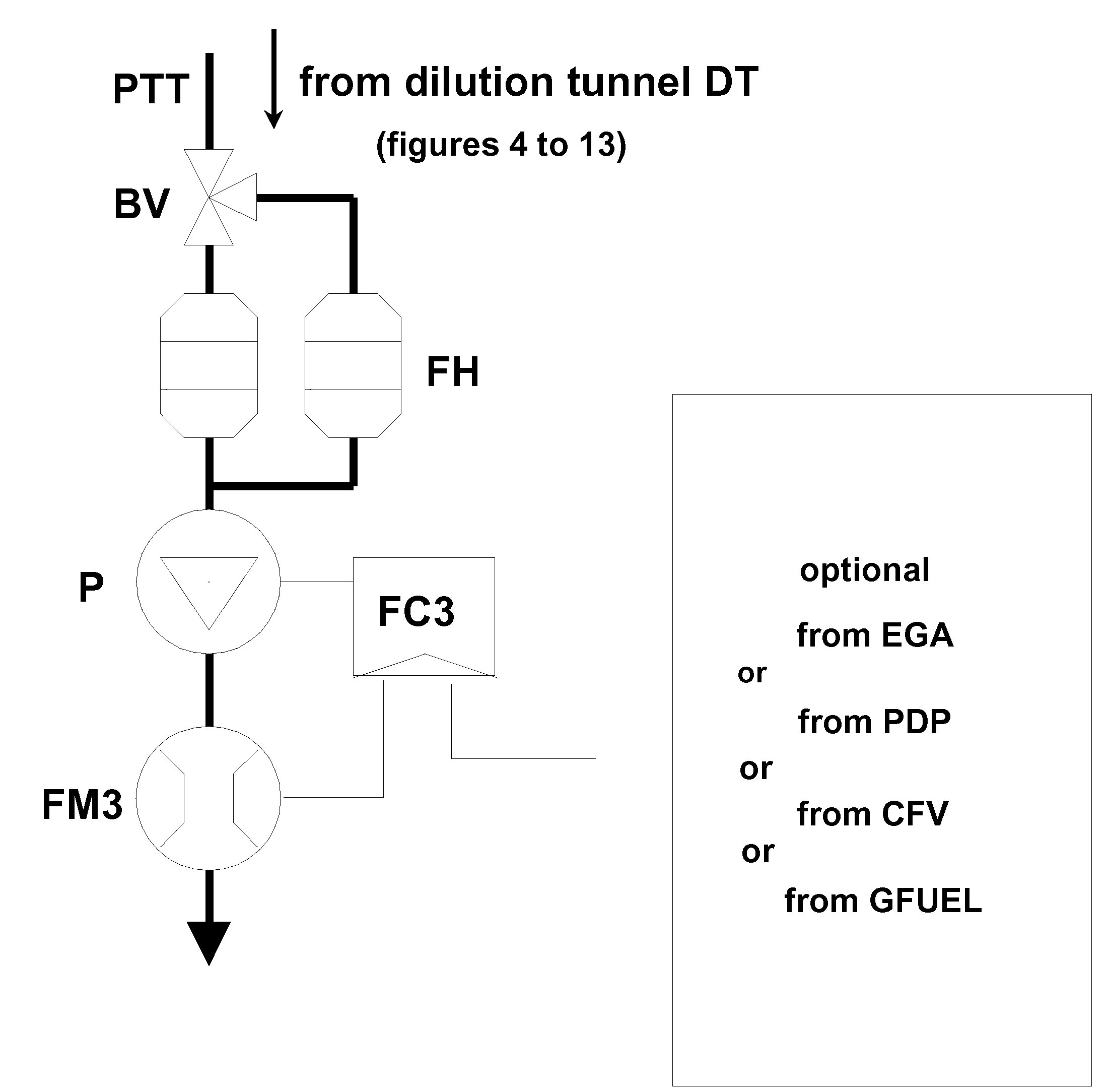
A sample of the diluted exhaust gas is taken from the dilution tunnel DT of a partial flow or full flow dilution system through the particulate sampling probe PSP and the particulate transfer tube PTT by means of the sampling pump P. The sample is passed through the filter holders(s) FH that contain the particulate sampling filters. The sample flow rate is controlled by the flow controller FC3. If electronic flow compensation EFC (Figure 13) is used, the diluted exhaust gas flow is used as command signal for FC3.
Figure 15
Dilution system (full flow system only)

A sample of the diluted exhaust gas is transferred from the dilution tunnel DT of a full flow dilution system through the particulate sampling probe PSP and the particulate transfer tube PTT to the secondary dilution tunnel SDT, where it is diluted once more. The sample is then passed through the filter holder(s) FH that contain the particulate sampling filters. The dilution air flow rate is usually constant whereas the sample flow rate is controlled by the flow controller FC3. If electronic flow compensation EFC (Figure 13) is used, the total diluted exhaust gas flow is used as command signal for FC3.
— PTT particulate transfer tube (Figures 14 and 15)
The particulate transfer tube must not exceed 1 020 mm in length, and must be minimised in length whenever possible.
The dimensions are valid for:
— the partial flow dilution fractional sampling type and the full flow single dilution system from the probe tip to the filter holder,
— the partial flow dilution total sampling type from the end of the dilution tunnel to the filter holder,
— the full flow double dilution system from the probe tip to the secondary dilution tunnel.
The transfer tube:
— may be heated to no greater than 325 K (52 °C) wall temperature by direct heating or by dilution air pre-heating, provided the air temperature does not exceed 325 K (52 °C) prior to the introduction of the exhaust in the dilution tunnel,
— SDT secondary dilution tunnel (Figure 15)
The secondary dilution tunnel should have a minimum diameter of 75 mm and should be sufficient length so as to provide a residence time of at least 0,25 seconds for the doubly-diluted sample. The primary filter holder, FH, shall be located within 300 mm of the exit of the SDT.
The secondary dilution tunnel:
— may be heated to no greater than 325 K (52 °C) wall temperature by direct heating or by dilution air pre-heating, provided the air temperature does not exceed 325 K (52 °C) prior to the introduction of the exhaust in the dilution tunnel,
— FH filter holder(s) (Figures 14 and 15)
For primary and back-up filters one filter housing or separate filter housings may be used. The requirements of Annex III, Appendix 1, section 1.5.1.3 have to be met.
The filter holder(s):
— may be heated to no greater than 325 K (52 °C) wall temperature by direct heating or by dilution air pre-heating, provided the air temperature does not exceed 325 K (52 °C),
— P sampling pump (Figures 14 and 15)
The particulate sampling pump shall be located sufficiently distant from the tunnel so that the inlet gas temperature is maintained constant (± 3 K), if flow correction by FC3 is not used.
— DP dilution air pump (Figure 15) (full flow double dilution only)
The dilution air pump shall be located so that the secondary dilution air is supplied at a temperature of 298 K (25 °C) ± 5 K.
— FC3 flow controller (Figures 14 and 15)
A flow controller shall be used to compensate the particulate sample flow rate for temperature and backpressure variations in the sample path, if no other means are available. The flow controller is required if electronic flow compensation EFC (Figure 13) is used.
— FM3 flow measurement device (Figures 14 and 15) (particulate sample flow)
The gas meter or flow instrumentation shall be located sufficiently distant from the sample pump so that the inlet gas temperature remains constant (± 3 K), if flow correction by FC3 is not used.
— FM4 flow measurement device (Figure 15) (dilution air, full flow double dilution only)
The gas meter or flow instrumentation shall be located so that the inlet gas temperature remains at 298 K (25 °C) ± 5 K.
— BV ball valve (optional)
The ball valve shall have a diameter not less than the inside diameter of the sampling tube and a switching time of less than 0,5 seconds.
Note: If the ambient temperature in the vicinity of PSP, PTT, SDT, and FH is below 239 K (20 °C), precautions should be taken to avoid particle losses onto the cool wall of these parts. Therefore, heating and/or insulating these parts within the limits given in the respective descriptions is recommended. It is also recommended that the filter face temperature during sampling be not below 293 K (20 °C).
At high engine loads, the above parts may be cooled by a non-aggressive means such as a circulating fan, as long as the temperature of the cooling medium is not below 293 K (20 °C).
▼M8
|
1.a.
|
This Annex applies as follows:
(a) for stages I, II, IIIA, IIIB and IV the requirements of Section 1 of this Annex shall apply;
(b) if the manufacturer, based on the option indicated in Section 1.2.1 of this Annex, chooses to use the procedure of Annex 4B to UNECE Regulation No 96.03 series of amendments, Section 9 of Annex 4B to UNECE Regulation No 96.03 series of amendments shall apply.
|
▼B
ANNEX
►M2
VII ◄
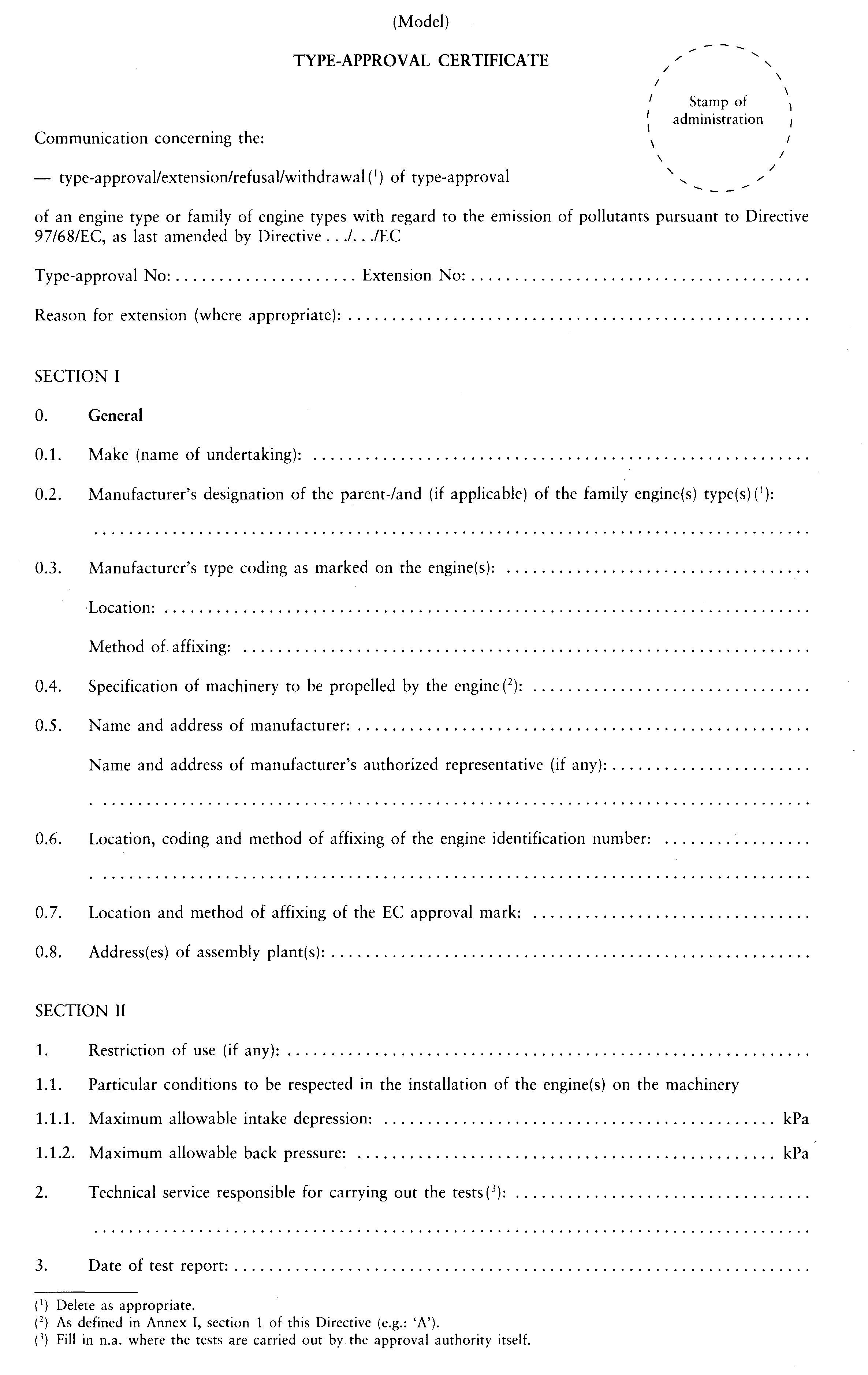
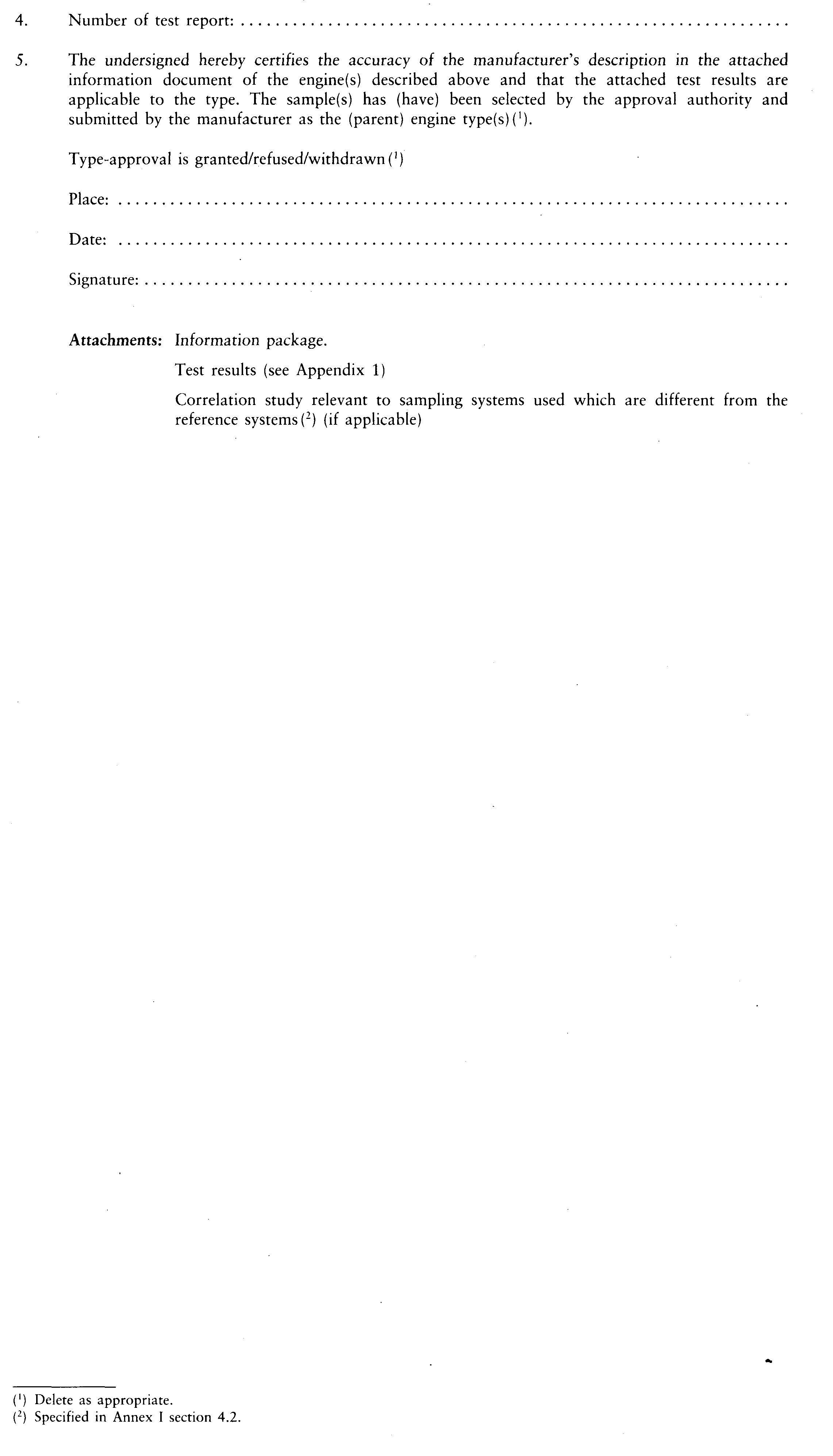
▼M8
Appendix 1
Test report for compression ignition engines test results (
31
)
Information concerning the test engine
Engine type: …
Engine identification number: …
|
1.
|
Information concerning the conduct of the test: …
1.1. Reference fuel used for test
|
1.1.2.
|
Sulphur content: …
|
1.2. Lubricant
|
1.2.2.
|
Type(s): …
(state percentage of oil in mixture if lubricant and fuel are mixed)
|
1.3. Engine driven equipment (if applicable)
|
1.3.1.
|
Enumeration and identifying details: …
|
|
1.3.2.
|
Power absorbed at indicated engine speeds (as specified by the manufacturer):
|
|
Power PAE (kW) absorbed at various engine speeds (1) (2), taking into account Appendix 3 to this Annex
|
|
Equipment
|
Intermediate speed
(if applicable)
|
Maximum power speed
(if different from rated)
|
Rated speed (3)
|
|
|
|
|
|
|
|
|
|
|
|
|
|
|
|
|
|
|
|
|
|
Total:
|
|
|
|
|
(1) Delete as appropriate.
(2) Shall not be greater than 10 per cent of the power measured during the test.
(3) Insert values at engine speed corresponding to 100 % normalised speed if NRSC test uses this speed.
|
|
1.4. Engine performance
|
1.4.1.
|
Engine speeds:
Idle: … min–1
Intermediate: … min–1
Maximum power: … min–1
Rated (
32
): … min–1
|
|
1.4.2.
|
Engine power (
33
)
|
|
Power setting (kW) at various engine speeds
|
|
Condition
|
Intermediate speed
(if applicable)
|
Maximum power speed
(if different from rated)
|
Rated speed (1)
|
|
Maximum power measured at specified test speed (PM) (kW) (a)
|
|
|
|
|
Total power absorbed by engine driven equipment as per paragraph 1.3.2 of this Appendix taking into account Appendix 3 (kW) (b)
|
|
|
|
|
Net engine power as specified in Section 2.4 of Annex I (kW) (c)
|
|
|
|
|

|
|
|
|
|
(1) Replace with values at engine speed corresponding to 100 % normalised speed if NRSC test uses this speed.
|
|
|
|
2.
|
Information concerning the conduct of the NRSC test:
2.1. Dynamometer setting (kW)
|
|
Dynamometer setting (kW) at various engine speeds
|
|
Per cent load
|
Intermediate speed
(if applicable)
|
63 %
(if applicable)
|
80 %
(if applicable)
|
91 %
(if applicable)
|
Rated speed (1)
|
|
10
(if applicable)
|
|
|
|
|
|
|
25
(if applicable)
|
|
|
|
|
|
|
50
|
|
|
|
|
|
|
75
(if applicable)
|
|
|
|
|
|
|
100
|
|
|
|
|
|
|
(1) Replace with values at engine speed corresponding to 100 % normalised speed if NRSC test uses this speed.
|
2.2. Emission results of the engine/parent engine (
34
)
Deterioration Factor (DF): calculated/fixed (34 36 38)
Specify the DF values and the emission results in the following table (34 36 38) :
|
NRSC test
|
|
DF
mult/add3
|
CO
|
HC
|
NOx
|
HC + NOx
|
PM
|
|
|
|
|
|
|
|
|
Emissions
|
CO
(g/kWh)
|
HC
(g/kWh)
|
NOx
(g/kWh)
|
HC + NOx
(g/kWh)
|
PM
(g/kWh)
|
CO2
(g/kWh)
|
|
Test result
|
|
|
|
|
|
|
|
Final test result with DF
|
|
|
|
|
|
|
|
Additional control area test points (if applicable)
|
|
Emissions at test point
|
Engine speed
|
Load
(%)
|
CO
(g/kWh)
|
HC
(g/kWh)
|
NOx
(g/kWh)
|
PM
(g/kWh)
|
|
Test result 1
|
|
|
|
|
|
|
|
Test result 2
|
|
|
|
|
|
|
|
Test result 3
|
|
|
|
|
|
|
|
2.3.
|
Sampling system used for the NRSC test:
|
2.3.1.
|
Gaseous emissions (
35
): …
|
|
2.3.2.
|
PM (35 37) : …
|
2.3.2.1.
|
Method (
36
): single/multiple filter
|
|
|
|
|
3.
|
Information concerning the conduct of the NRTC test (if applicable):
3.1. Emission results of the engine/parent engine (34 36 38)
|
NRTC test
|
|
DF
mult/add (1)
|
CO
|
HC
|
NOx
|
HC + NOx
|
PM
|
|
|
|
|
|
|
|
|
Emissions
|
CO
(g/kWh)
|
HC
(g/kWh)
|
NOx
(g/kWh)
|
HC + NOx
(g/kWh)
|
PM
(g/kWh)
|
|
Cold start
|
|
|
|
|
|
|
Emissions
|
CO
(g/kWh)
|
HC
(g/kWh)
|
NOx
(g/kWh)
|
HC + NOx
(g/kWh)
|
PM
(g/kWh)
|
CO2
(g/kWh)
|
|
Hot start w/o regeneration
|
|
|
|
|
|
|
|
Hot start with regeneration (1)
|
|
|
|
|
|
|
|
kr,u
(mult/add) (1)
kr,d
(mult/add) (1)
|
|
|
|
|
|
|
Weighted test result
|
|
|
|
|
|
|
Final test result with DF
|
|
|
|
|
|
|
(1) Delete as appropriate.
|
Cycle work for hot start w/o regeneration kWh
|
3.2.
|
Sampling system used for the NRTC test:
Gaseous emissions (
37
): …
PM (35 37) : …
Method (
38
): single/multiple filter
|
|
▼M2
Appendix 2
TEST RESULTS FOR SPARK IGNITION ENGINES
1. INFORMATION CONCERNING THE CONDUCT OF THE TEST(S) (
39
):
1.1. Octane number
|
1.1.2.
|
State percentage of oil in mixture when lubricant and petrol are mixed as in the case of two-stroke engines
|
|
1.1.3.
|
Density of petrol for four-stroke engines and petrol/oil mixture for two-stroke engines
|
1.2. Lubricant
1.3. Engine driven equipment (if applicable)
|
1.3.1.
|
Enumeration and identifying details
|
|
1.3.2.
|
Power absorbed at indicated engine speed (as specified by the manufacturer)
|
Equipment
|
Power PAE (kW) absorbed at various engine speeds (1), taking into account Appendix 3 of this Annex
|
|
Equipment
|
Rated
|
|
Total
|
|
|
|
(1) Must not be greater than 10 % of the power measured during the test.
|
|
1.4. Engine performance
|
1.4.1.
|
Engine speeds:
Idle: min-1
Intermediate: min-1
Rated: min-1
|
|
1.4.2.
|
Engine power (
40
)
|
Condition
|
Power setting (kW) at various engine speeds
|
|
Intermediate (if applicable)
|
Rated
|
|
Maximum power measured on test (PM) (kW) (a)
|
|
|
|
Total power absorbed by engine driven equipment as per section 1.3.2 of this Appendix, or section 2.8 of Annex III (PAE) (kW) (b)
|
|
|
|
Net engine power as specified in section 2.4 of Annex I (kW) (c)
|
|
|
|
c = a + b
|
|
|
|
1.5. Emission levels
|
1.5.1.
|
Dynamometer setting (kW)
|
Percent Load
|
Dynamometer setting (kW) at various engine speeds
|
|
Intermediate (if applicable)
|
Rated (if applicable)
|
|
10 (if applicable)
|
|
|
|
25 (if applicable)
|
|
|
|
50
|
|
|
|
75
|
|
|
|
100
|
|
|
|
|
1.5.2.
|
Emission results on the test cycle:
|
Appendix 3
EQUIPMENT AND AUXILIARIES TO BE INSTALLED FOR THE TEST TO DETERMINE ENGINE POWER
|
Number
|
Equipment and auxiliaries
|
Fitted for emission test
|
|
1
|
Inlet system
|
|
|
Inlet manifold
|
Yes, standard production equipment
|
|
Crankcase emission control system
|
Yes, standard production equipment
|
|
Control devices for dual induction inlet manifold system
|
Yes, standard production equipment
|
|
Air flow meter
|
Yes, standard production equipment
|
|
Air inlet duct work
|
Yes ()
|
|
Air filter
|
Yes ()
|
|
Inlet silencer
|
Yes ()
|
|
Speed-limiting device
|
Yes ()
|
|
2
|
Induction-heating device of inlet manifold
|
Yes, standard production equipment. If possible to be set in the most favourable condition
|
|
3
|
Exhaust system
|
|
|
Exhaust purifier
|
Yes, standard production equipment
|
|
Exhaust manifold
|
Yes, standard production equipment
|
|
Connecting pipes
|
Yes ()
|
|
Silencer
|
Yes ()
|
|
Tail pipe
|
Yes ()
|
|
Exhaust brake
|
No ()
|
|
Pressure charging device
|
Yes, standard production equipment
|
|
4
|
Fuel supply pump
|
Yes, standard production equipment ()
|
|
5
|
Carburation equipment
|
|
|
Carburettor
|
Yes, standard production equipment
|
|
Electronic control system, air flow meter, etc.
|
Yes, standard production equipment
|
|
Equipment for gas engines
|
|
|
Pressure reducer
|
Yes, standard production equipment
|
|
Evaporator
|
Yes, standard production equipment
|
|
Mixer
|
Yes, standard production equipment
|
|
6
|
Fuel injection equipment (petrol and diesel)
|
|
|
Prefilter
|
Yes, standard production or test bed equipment
|
|
Filter
|
Yes, standard production or test bed equipment
|
|
Pump
|
Yes, standard production equipment
|
|
High-pressure pipe
|
Yes, standard production equipment
|
|
Injector
|
Yes, standard production equipment
|
|
Air inlet valve
|
Yes, standard production equipment ()
|
|
Electronic control system, air flow meter, etc.
|
Yes, standard production equipment
|
|
Governor/control system
|
Yes, standard production equipment
|
|
Automatic full-load stop for the control rack depending on atmospheric conditions
|
Yes, standard production equipment
|
|
7
|
Liquid-cooling equipment
|
|
|
Radiator
|
No
|
|
Fan
|
No
|
|
Fan cowl
|
No
|
|
Water pump
|
Yes, standard production equipment ()
|
|
Thermostat
|
Yes, standard production equipment ()
|
|
8
|
Air cooling
|
|
|
Cowl
|
No ()
|
|
Fan or Blower
|
No ()
|
|
Temperature-regulating device
|
No
|
|
9
|
Electrical equipment
|
|
|
Generator
|
Yes, standard production equipment ()
|
|
Spark distribution system
|
Yes, standard production equipment
|
|
Coil or coils
|
Yes, standard production equipment
|
|
Wiring
|
Yes, standard production equipment
|
|
Spark plugs
|
Yes, standard production equipment
|
|
Electronic control system including knock sensor/spark retard system
|
Yes, standard production equipment
|
|
10
|
Pressure charging equi pment
|
|
|
Compressor driven either directly by the engine and/or by the exhaust gases
|
Yes, standard production equipment
|
|
Charge air cooler
|
Yes, standard production or test bed equipment () ()
|
|
Coolant pump or fan (engine-driven)
|
No ()
|
|
Coolant flow control device
|
Yes, standard production equipment
|
|
11
|
Auxiliary test-bed fan
|
Yes, if necessary
|
|
12
|
Anti-pollution device
|
Yes, standard production equipment ()
|
|
13
|
Starting equipment
|
Test bed equipment
|
|
14
|
Lubricating oil pump
|
Yes, standard production equipment
|
|
(1) The complete inlet system shall be fitted as provided for the intended application: where there is a risk of an appreciable effect on the engine power; in the case of naturally aspirated spark ignition engines; when the manufacturer requests that this should be done.
(2) The complete exhaust system shall be fitted as provided for the intended application: where there is a risk of an appreciable effect on the engine power; in the case of naturally aspirated spark ignition engines; when the manufacturer requests that this should be done.
(3) If an exhaust brake is incorporated in the engine, the throttle valve shall be fixed in the fully open position.
(4) The fuel feed pressure may be adjusted, if necessary, to reproduce the pressure existing in the particular engine application (particularly when a ‘fuel return’ system is used).
(5) The air intake valve is the control valve for the pneumatic governor of the injection pump. The governor or the fuel injection equipment may contain other devices which may affect the amount of injected fuel.
(6) The cooling-liquid circulation shall be operated by the engine water pump only. Cooling of the liquid may be produced by an external circuit, such that the pressure loss of this circuit and the pressure at the pump inlet remain substantially the same as those of the engine cooling system.
(7) The thermostat may be fixed in the fully open position.
(8) When the cooling fan or blower is fitted for the test, the power absorbed shall be added to the results, except for cooling fans of air cooled engines directly fitted on the crankshaft. The fan or blower power shall be determined at the speeds used for the test either by calculation from standard characteristics or by practical tests.
(9) Minimum power of the generator: the electrical power of the generator shall be limited to that necessary for operation of accessories which are indispensable for engine operation. If the connection of a battery is necessary, a fully charged battery in good condition shall be used.
(10) Charge air-cooled engines shall be tested with charge air cooling, whether liquid- or air-cooled, but if the manufacturer prefers, a test bench system may replace the air cooler. In either case, the measurement of power at each speed shall be made with the maximum pressure drop and the minimum temperature drop of the engine air across the charge air cooler on the test bench system as specified by the manufacturer.
(11) These may include, for example, exhaust-gas recirculation (EGR)-system, catalytic converter, thermal reactor, secondary air-supply system and fuel evaporation protecting system.
(12) The power for electrical or other starting systems shall be provided from the test bed.
|
▼B
ANNEX
►M2
VIII ◄
APPROVAL CERTIFICATE NUMBERING SYSTEM
(see Article 4 (2))
|
1.
|
The number shall consist of five sections separated by the ‘*’ character.
|
Section 1
|
:
|
the lower case letter ‘e’ followed by the distinguishing letter(s) or number of the Member State issuing the approval:
▼M4
|
11
|
for the United Kingdom
|
▼B
|
|
Section 2
|
:
|
the number of this Directive. As it contains different implementation dates and different technical standards, two alphabetical characters are added. These characters refer to the different application dates for the stages of severity and to the application of the engine for different specification of mobile machinery, on the basis of which type-approval was granted. The first character is defined in Article 9. The second character is defined in Annex I, section 1 with regard to the test mode defined in Annex III, section 3.6.
|
|
Section 3
|
:
|
the number of the latest amending Directive applicable to the approval. If applicable two further alphabetical characters are to be added depending on the conditions described in section 2, even if as a result of the new parameters only one of the characters was to be changed. If no change of these characters apply they shall be omitted.
|
|
Section 4
|
:
|
a four-digit sequential number (with leading zeros as applicable) to denote the base approval number. The sequence shall start from 0001.
|
|
Section 5
|
:
|
a two-digit sequential number (with a leading zero if applicable) to denote the extension. The sequence shall start from 01 for each base approval number.
|
|
|
2.
|
Example for the third approval (with, as yet, no extension) corresponding to application date A (stage I, upper powerband) and to the application of the engine for specification A of mobile machinery, issued by the United Kingdom:
e 11*98/…AA*00/000XX*0003*00
|
|
3.
|
Example of the second extension to the fourth approval corresponding to application date E (stage II, medium powerband) for the same specification of machinery (A), issued by Germany:
e 1*01/…EA*00/000XX*0004*02
|
ANNEX
►M2
IX ◄
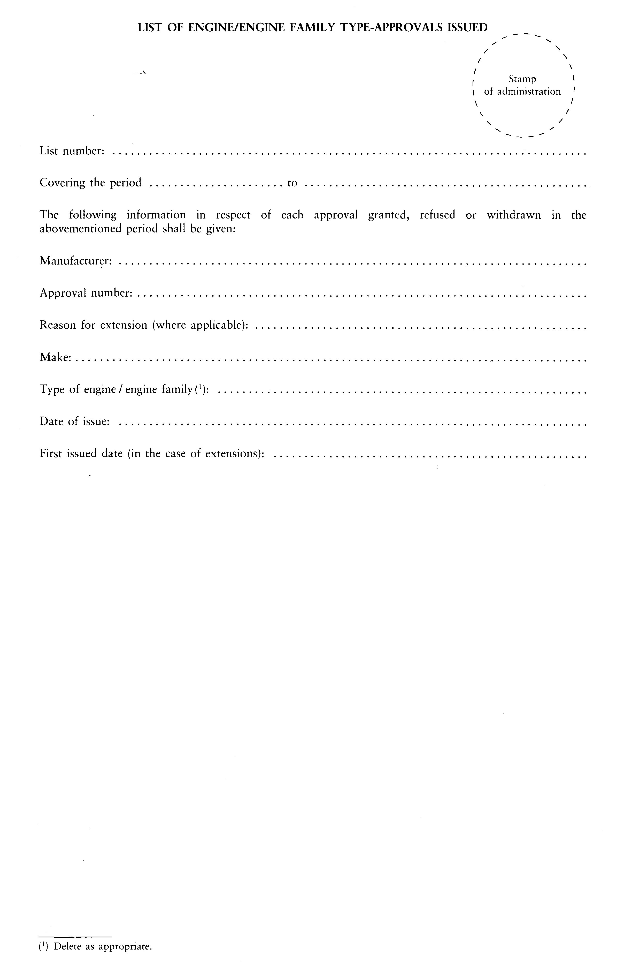
ANNEX
►M2
X ◄

▼M8
ANNEX XI
DATA SHEET OF TYPE-APPROVED ENGINES
1.
SI Engines

|
Reported engine type approval
|
1
|
2
|
3
|
4
|
|
Type approval number
|
|
|
|
|
|
Date of approval
|
|
|
|
|
|
Name of manufacturer
|
|
|
|
|
|
Engine type/family
|
|
|
|
|
|
Engine description
|
General information (1)
|
|
|
|
|
|
Cooling medium (1)
|
|
|
|
|
|
Number of cylinders
|
|
|
|
|
|
Swept volume (cm3)
|
|
|
|
|
|
Type of after-treatment (2)
|
|
|
|
|
|
Rated speed (min–1)
|
|
|
|
|
|
Rated net power (kW)
|
|
|
|
|
|
Emissions (g/kWh)
|
CO
|
|
|
|
|
|
HC
|
|
|
|
|
|
NOx
|
|
|
|
|
|
PM
|
|
|
|
|
|
(1) Liquid or air.
(2) Abbreviate: CAT = catalyst, PT = particulate trap, SCR = selective catalytic reduction.
|
2.
CI Engines (
41
) (
42
)

2.1.
General engine information
|
Reported engine type approval
|
1
|
2
|
3
|
4
|
|
Type approval number
|
|
|
|
|
|
Date of approval
|
|
|
|
|
|
Name of manufacturer
|
|
|
|
|
|
Engine type/family
|
|
|
|
|
|
Engine description
|
General information (1)
|
|
|
|
|
|
Cooling medium (2)
|
|
|
|
|
|
Number of cylinders
|
|
|
|
|
|
Swept volume (cm3)
|
|
|
|
|
|
Type of after-treatment (3)
|
|
|
|
|
|
Rated speed (min–1)
|
|
|
|
|
|
Maximum power speed (min–1)
|
|
|
|
|
|
Rated net power (kW)
|
|
|
|
|
|
Maximum net power (kW)
|
|
|
|
|
|
(1) Abbreviate: DI = direct injection, PC = pre/swirl chamber, NA = naturally aspirated, TC = turbocharged, TCA = turbocharged including after-cooling, EGR = Exhaust gas recirculation. Examples: PC NA, DI TCA EGR.
(2) Liquid or air.
(3) Abbreviate: DOC = diesel oxidation catalyst, PT = particulate trap, SCR = selective catalytic reduction.
|
2.2.
Final emission result
|
Reported engine type approval
|
1
|
2
|
3
|
4
|
|
NRSC final test result inclusive of DF (g/kWh)
|
CO
|
|
|
|
|
|
HC
|
|
|
|
|
|
NOx
|
|
|
|
|
|
HC + NOx
|
|
|
|
|
|
PM
|
|
|
|
|
|
NRSC CO2 (g/kWh)
|
|
|
|
|
|
NRTC final test result inclusive of DF (g/kWh)
|
CO
|
|
|
|
|
|
HC
|
|
|
|
|
|
NOx
|
|
|
|
|
|
HC + NOx
|
|
|
|
|
|
PM
|
|
|
|
|
|
NRTC hot cycle CO2 (g/kWh)
|
|
|
|
|
|
NRTC hot cycle work (kWh)
|
|
|
|
|
2.3.
NRSC deterioration factors and emission test results
|
Reported engine type approval
|
1
|
2
|
3
|
4
|
|
DF mult/add (1)
|
CO
|
|
|
|
|
|
HC
|
|
|
|
|
|
NOx
|
|
|
|
|
|
HC + NOx
|
|
|
|
|
|
PM
|
|
|
|
|
|
NRSC test result exclusive of DF (g/kWh)
|
CO
|
|
|
|
|
|
HC
|
|
|
|
|
|
NOx
|
|
|
|
|
|
HC + NOx
|
|
|
|
|
|
PM
|
|
|
|
|
|
(1) Delete as appropriate.
|
2.4.
NRTC deterioration factors and emission test results
|
Reported engine type approval
|
1
|
2
|
3
|
4
|
|
DF mult/add (1)
|
CO
|
|
|
|
|
|
HC
|
|
|
|
|
|
NOx
|
|
|
|
|
|
HC + NOx
|
|
|
|
|
|
PM
|
|
|
|
|
|
NRTC cold start test result exclusive of DF (g/kWh)
|
CO
|
|
|
|
|
|
HC
|
|
|
|
|
|
NOx
|
|
|
|
|
|
HC + NOx
|
|
|
|
|
|
PM
|
|
|
|
|
|
NRTC hot start test result exclusive of DF (g/kWh)
|
CO
|
|
|
|
|
|
HC
|
|
|
|
|
|
NOx
|
|
|
|
|
|
HC + NOx
|
|
|
|
|
|
PM
|
|
|
|
|
|
(1) Delete as appropriate.
|
2.5.
NRTC hot start emission test results
Regeneration related data may be reported for Stage IV engines.
|
Reported engine type approval
|
1
|
2
|
3
|
4
|
|
NRTC hot start w/o regeneration (g/kWh)
|
CO
|
|
|
|
|
|
HC
|
|
|
|
|
|
NOx
|
|
|
|
|
|
HC + NOx
|
|
|
|
|
|
PM
|
|
|
|
|
|
NRTC hot start with regeneration (g/kWh)
|
CO
|
|
|
|
|
|
HC
|
|
|
|
|
|
NOx
|
|
|
|
|
|
HC + NOx
|
|
|
|
|
|
PM
|
|
|
|
|
ANNEX XII
RECOGNITION OF ALTERNATIVE TYPE-APPROVALS
1. The following type-approvals and, where applicable, the pertaining approval marks are recognised as being equivalent to an approval to this Directive for engines of categories A, B and C as defined in Article 9(2):
1.1. Type approvals to Directive 2000/25/EC;
1.2. Type-approvals to Directive 88/77/EEC, complying with the requirements of stages A or B regarding Article 2 and Annex I, Section 6.2.1 of Directive 88/77/EEC or UNECE Regulation No 49.02 series of amendments, corrigenda I/2;
1.3. Type approvals according to UNECE Regulation No 96.
2. For engines categories D, E, F and G (stage II) as defined in Article 9(3), the following type-approvals and, where applicable, the pertaining approval marks are recognised as being equivalent to an approval to this Directive:
2.1. Directive 2000/25/EC, stage II approvals;
2.2. Type-approvals to Directive 88/77/EEC as amended by Directive 99/96/EC which are in compliance with stages A, B1, B2 or C provided for in Article 2 and Section 6.2.1 of Annex I to that Directive;
2.3. Type-approvals to UNECE Regulation No 49.03 series of amendments;
2.4. UNECE Regulation No 96 stages D, E, F and G approvals according to paragraph 5.2.1 of the 01 series of amendments of Regulation No 96.
3. For engines categories H, I, J and K (stage IIIA) as defined in Article 9(3a) and Article 9(3b), the following type-approvals and, where applicable, the pertaining approval marks are recognised as being equivalent to an approval to this Directive:
3.1. Type-approvals to Directive 2005/55/EC, as amended by Directives 2005/78/EC and 2006/51/EC, which are in compliance with stages B1, B2 or C provided for in Article 2 and Section 6.2.1 of Annex I to that Directive;
3.2. Type-approvals to UNECE Regulation No 49.05 series of amendments, which are in compliance with stages B1, B2 and C provided for in paragraph 5.2 of that Regulation;
3.3. UNECE Regulation No 96 stages H, I, J and K approvals according to paragraph 5.2.1 of the 02 series of amendments of Regulation No 96.
4. For engines categories L, M, N and P (stage IIIB) as defined in Article 9(3c), the following type-approvals and, where applicable, the pertaining approval marks are recognised as being equivalent to an approval to this Directive:
4.1. Type-approvals to Directive 2005/55/EC, as amended by Directives 2005/78/EC and 2006/51/EC, which are in compliance with stages B2 or C provided for in Article 2 and Section 6.2.1 of Annex I to that Directive;
4.2. Type-approvals to UNECE Regulation No 49.05 series of amendments, which are in compliance with stages B2 or C provided for in paragraph 5.2 of that regulation;
4.3. UNECE Regulation No 96 stages L, M, N and P approvals according to paragraph 5.2.1 of the 03 series of amendments of Regulation No 96.
5. For engines categories Q and R (stage IV) as defined in Article 9(3d), the following type-approvals and, where applicable, the pertaining approval marks are recognised as being equivalent to an approval to this Directive:
5.1. Type-approvals to Regulation (EC) No 595/2009 and its implementing measures, if it is confirmed by a technical service that the engine meets the requirements of Annex I Section 8.5 to this Directive;
5.2. Type-approvals to UNECE Regulation No 49.06 series of amendments, if it is confirmed by a technical service that the engine meets the requirements of Annex I Section 8.5 to this Directive.
▼M3
ANNEX XIII
PROVISIONS FOR ENGINES PLACED ON THE MARKET UNDER A ‘FLEXIBLE SCHEME’
On the request of an equipment manufacturer (OEM), and permission being granted by an approval authority, an engine manufacturer may during the period between two successive stages of limit values place a limited number of engines on the market that only comply with the previous stage of emission limit values in accordance with the following provisions:
▼M7
1. ACTIONS BY THE OEM
1.1. Except during Stage III B, an OEM that wishes to make use of the flexibility scheme, with the exception of engines for the propulsion of railcars and locomotives, shall request permission from any approval authority for the OEM’s engine manufacturers to place on the market engines intended for the OEM’s exclusive use. The number of engines that do not comply with the current emission limits, but are approved to the most recent previous stage of emission limits, shall not exceed the ceilings set out in Sections 1.1.1 and 1.1.2.
1.1.1. The number of engines placed on the market under the flexibility scheme shall, in each engine category, not exceed 20 % of the annual quantity of equipment with engines in that category that is placed on the market by the OEM (calculated as an average of the latest 5 years’ sales on the Union market). Where an OEM has placed equipment on the Union market for less than 5 years, the average shall be calculated based on the period for which the OEM has placed equipment on the Union market.
1.1.2. As an optional alternative to Section 1.1.1 and with the exception of engines for the propulsion of railcars and locomotives, the OEM may seek permission for the OEM’s engine manufacturers to place on the market a fixed number of engines for the OEM’s exclusive use. The number of engines in each engine category shall not exceed the following ceilings:
|
Engine category P (kW)
|
Number of engines
|
|
19 ≤ P < 37
|
200
|
|
37 ≤ P < 75
|
150
|
|
75 ≤ P < 130
|
100
|
|
130 ≤ P ≤ 560
|
50
|
1.2. During Stage III B, but for a period no longer than 3 years from the beginning of that stage, with the exception of engines for use in the propulsion of railcars and locomotives, an OEM that wishes to make use of the flexibility scheme shall request permission from any approval authority for the OEM’s engine manufacturers to place on the market engines intended for the OEM’s exclusive use. The quantities of engines that do not comply with the current emission limits, but are approved to the most recent previous stage of emission limits, shall not exceed the ceilings set out in Sections 1.2.1 and 1.2.2.
1.2.1. The number of engines placed on the market under the flexibility scheme shall, in each engine category, not exceed 37,5 % of the annual quantity of equipment with engines in that category that is placed on the market by the OEM (calculated as an average of the latest 5 years’ sales on the Union market). Where an OEM has placed equipment on the Union market for less than 5 years, the average shall be calculated based on the period for which the OEM has placed equipment on the Union market.
1.2.2. As an optional alternative to Section 1.2.1, the OEM may seek permission for the OEM’s engine manufacturers to place on the market a fixed number of engines for the OEM’s exclusive use. The number of engines in each engine category shall not exceed the following ceilings:
|
Engine category P (kW)
|
Number of engines
|
|
37 ≤ P < 56
|
200
|
|
56 ≤ P < 75
|
175
|
|
75 ≤ P < 130
|
250
|
|
130 ≤ P ≤ 560
|
125
|
1.3. As regards engines for use in the propulsion of locomotives, during Stage III B, but for a period no longer than 3 years from the beginning of that stage, an OEM may seek permission for the OEM’s engine manufacturers to place on the market a maximum of 16 engines for the OEM’s exclusive use. The OEM may also seek permission for his engine manufacturers to place on the market a maximum of 10 additional engines with rated powers greater than 1 800 kW to be installed in locomotives designed exclusively for use on the United Kingdom network. Locomotives will be considered to meet this requirement only if they have, or are able to be issued with, a safety certificate for operation on the United Kingdom network.
Such permission shall be granted only where there are technical grounds for not being able to comply with the Stage III B emission limits.
1.4. The OEM shall include in the application to an approval authority the following information:
(a) a sample of the labels to be affixed to each piece of non-road mobile machinery in which an engine placed on the market under the flexibility scheme will be installed. The labels shall bear the following text: ‘MACHINE No … (sequence of machines) OF … (total number of machines in respective power band) WITH ENGINE No … WITH TYPE-APPROVAL (Dir. 97/68/EC) No …’;
(b) a sample of the supplementary label to be affixed on the engine bearing the text referred to in Section 2.2.
1.5. The OEM shall provide the approval authority with any necessary information connected with the implementation of the flexibility scheme that the approval authority may request in order to make a decision.
1.6. The OEM shall provide any requesting approval authority in the Member States with any information that the approval authority requires in order to confirm that engines claimed to be, or labelled as being, placed on the market under the flexibility scheme are properly so claimed or labelled.
▼C1
2. ACTIONS BY THE ENGINE MANUFACTURER
2.1. An engine manufacturer may place on the market engines under a flexible scheme covered by an approval in accordance with Section 1 of this Annex.
2.2. The engine manufacturer must put a label on those engines with the following text: ‘Engine placed on the market under the flexibility scheme’.
3. ACTIONS BY THE APPROVAL AUTHORITY
3.1. The approval authority shall evaluate the content of the flexibility scheme request and the enclosed documents. As a consequence it will inform the OEM of its decision as to whether or not to allow use of the flexibility scheme.
▼M3
ANNEX XIV
CCNR stage I (
43
)
|
PN
(kW)
|
CO
(g/kWh)
|
HC
(g/kWh)
|
NOx
(g/k/Wh)
|
PT
(g/kWh)
|
|
37 ≤ PN < 75
|
6,5
|
1,3
|
9,2
|
0,85
|
|
75 ≤ PN < 130
|
5,0
|
1,3
|
9,2
|
0,70
|
|
P ≥ 130
|
5,0
|
1,3
|
n ≥ 2 800 tr/min = 9,2
500 ≤ n < 2 800 tr/min = 45 x n(-0.2)
|
0,54
|
ANNEX XV
CCNR stage II (
44
)
|
PN
(kW)
|
CO
(g/kWh)
|
HC
(g/kWh)
|
NOx
(g/kWh)
|
PT
(g/kWh)
|
|
18 ≤ PN < 37
|
5,5
|
1,5
|
8,0
|
0,8
|
|
37 ≤ PN < 75
|
5,0
|
1,3
|
7,0
|
0,4
|
|
75 ≤ PN < 130
|
5,0
|
1,0
|
6,0
|
0,3
|
|
130 ≤ PN < 560
|
3,5
|
1,0
|
6,0
|
0,2
|
|
PN ≥ 560
|
3,5
|
1,0
|
n ≥ 3150 min-1 = 6,0
343 ≤ n < 3150 min-1= 45 x n(-0,2) – 3
n < 343 min-1= 11,0
|
0,2
|
 is smaller than – 5 % of the peak torque, does not exceed 30 (where T
 where x is any one of the individual results obtained with the sample n.