

EUR-Lex Access to European Union law
This document is an excerpt from the EUR-Lex website
Document 01997L0024-20131211
Directive 97/24/EC of the European Parliament and of the Council of 17 June 1997 on certain components and characteristics of two or three-wheel motor vehicles
Consolidated text: Directive 97/24/EC of the European Parliament and of the Council of 17 June 1997 on certain components and characteristics of two or three-wheel motor vehicles
Directive 97/24/EC of the European Parliament and of the Council of 17 June 1997 on certain components and characteristics of two or three-wheel motor vehicles
 No longer in force
1997L0024 — EN — 11.12.2013 — 008.001
This document is meant purely as a documentation tool and the institutions do not assume any liability for its contents
|
DIRECTIVE 97/24/EC OF THE EUROPEAN PARLIAMENT AND OF THE COUNCIL of 17 June 1997 on certain components and characteristics of two or three-wheel motor vehicles (OJ L 226, 18.8.1997, p.1) |
Amended by:
|
|
|
Official Journal |
||
|
No |
page |
date |
||
|
L 252 |
20 |
20.9.2002 |
||
|
COMMISSION DIRECTIVE 2003/77/EC Text with EEA relevance of 11 August 2003 |
L 211 |
24 |
21.8.2003 |
|
|
COMMISSION DIRECTIVE 2005/30/EC Text with EEA relevance of 22 April 2005 |
L 106 |
17 |
27.4.2005 |
|
|
COMMISSION DIRECTIVE 2006/27/EC Text with EEA relevance of 3 March 2006 |
L 66 |
7 |
8.3.2006 |
|
|
COMMISSION DIRECTIVE 2006/72/EC Text with EEA relevance of 18 August 2006 |
L 227 |
43 |
19.8.2006 |
|
|
COMMISSION DIRECTIVE 2009/108/EC Text with EEA relevance of 17 August 2009 |
L 213 |
10 |
18.8.2009 |
|
|
COMMISSION DIRECTIVE 2013/60/EU Text with EEA relevance of 27 November 2013 |
L 329 |
15 |
10.12.2013 |
|
Corrected by:
DIRECTIVE 97/24/EC OF THE EUROPEAN PARLIAMENT AND OF THE COUNCIL
of 17 June 1997
on certain components and characteristics of two or three-wheel motor vehicles
THE EUROPEAN PARLIAMENT AND THE COUNCIL OF THE EUROPEAN UNION,
Having regard to the Treaty establishing the European Community, and in particular Article 100a thereof,
Having regard to the proposal from the Commission ( 1 ),
Having regard to the opinion of the Economic and Social Committee ( 2 ),
Acting in accordance with the procedure laid down in Article 189b of the Treaty ( 3 ) in the light of the joint text approved by the Conciliation Committee on 4 February 1997,
|
(1) |
Whereas it is necessary to adopt measures that are intended to ensure the operation of the internal market; |
|
(2) |
Whereas, in each Member State, two or three-wheel motor vehicles must, in respect of the components and characteristics covered by this Directive, satisfy certain mandatory technical requirements which differ from one Member State to another; whereas, owing to those differences, such requirements constitute barriers to trade within the Community; whereas those barriers to the operation of the internal market may be removed if the same requirements are adopted by all of the Member States in place of their national regulations; |
|
(3) |
Whereas the drawing-up of harmonized requirements concerning those components and characteristics of two and three-wheel motor vehicles is necessary in order to enable the type-approval and component type-approval procedures covered by Council Directive 92/61/EEC of 30 June 1992 relating to the type-approval of two or three-wheel vehicles ( 4 ) to be implemented in respect of each type of the aforesaid vehicles; |
|
(4) |
Whereas, in order to facilitate access to markets in third countries, it appears necessary to establish equivalence between the requirements of Chapters 1 (tyres), 2 (lighting and light-signalling devices), 4 (rear-view mirrors) and 11 (safety belts) of the Annex to this Directive and those of United Nations ECE Regulations Nos 30, 54, 64 and 75 in respect of tyres, 3, 19, 20, 37, 38, 50, 56, 57, 72 and 82 in respect of lighting and light-signalling devices, 81 in respect of rear-view mirrors and 16 in respect of safety belts; |
|
(5) |
Whereas, with regard to the aspects concerning the protection of the environment, namely atmospheric and noise pollution, it is necessary to pursue the aim of constantly improving the environment; whereas, for this purpose, limit values for pollutants and sound level must be laid down for the fastest possible application; whereas subsequent reductions in the limit values and changes in the testing procedure may be decided upon only on the basis of studies and research to be undertaken or pursued into the available or conceivable technological potential and into an analysis of their cost/benefit ratios in order to permit production, on an industrial scale, of vehicles which are able to meet these more stringent limits; whereas the decision on that subsequent reduction must be taken by the European Parliament and the Council at least three years before these limit values enter into force in order to enable the industry to take the necessary measures whereby their products may, by the intended date, comply with the new Community provisions; whereas the Decision of the European Parliament and of the Council will be based on proposals to be submitted by the Commission in due course; |
|
(6) |
Whereas, pursuant to the provisions of Directive 92/61/EEC, the components and characteristics covered by this Directive may not be placed on the market and sold in the Member States unless they comply with the provisions of this Directive; whereas the Member States must take all the necessary measures to ensure fulfilment of the obligations resulting from this Directive. |
|
(7) |
Whereas Member States should be enabled, by granting tax incentives, to promote the marketing of vehicles which, in advance, meet the requirements adopted at Community level concerning measures to counter pollutant and noise emissions; |
|
(8) |
Whereas the methods of measuring the immunity of vehicles and separate technical units to electromagnetic radiation in order to check compliance with the provisions concerning electromagnetic compatibility (Chapter 8) require complex and costly installations; whereas, in order to enable Member States to provide such installations, provision should be made for deferring application of these measuring methods by three years from the entry into force of this Directive; |
|
(9) |
Whereas, given the scale and impact of the action proposed in the sector in question, the Community measures which are the subject of this Directive are necessary, or even indispensable, to attain the objectives set, namely Community vehicle type approval; whereas these objectives cannot be adequately achieved by the Member States individually; |
|
(10) |
Whereas technical progress requires rapid adaptation of the technical requirements set out in the Annex to this Directive; whereas, with the exception of the limit values for pollutants and sound level, this task should be assigned to the Commission in order to simplify and speed up the procedure; whereas, in all cases where the European Parliament and the Council confer upon the Commission authority to implement rules laid down in the two or three-wheel motor vehicle sector, it is appropriate to provide for a procedure for prior consultation between the Commission and Member States within a committee; |
|
(11) |
Whereas safety or environmental requirements call for restrictions on tampering with certain types of two or three-wheel vehicle; whereas, if they are not to prove an obstacle to owner servicing and maintenance, such restrictions must be strictly limited to tampering which significantly modifies the vehicle's performance and pollutant and noise emissions; |
|
(12) |
Whereas, a long as vehicles conform to the requirements of this Directive, no Member State may refuse registration or use of them; whereas the object of the requirements of this Directive should not be to oblige those Member States which do not allow two or three-wheel motor vehicles in their territory to tow a trailer to amend their rules, |
HAVE ADOPTED THIS DIRECTIVE:
Article 1
This Directive and its Annex shall apply to:
— tyres,
— lighting and light-signalling devices,
— external projections,
— rear-view mirrors,
— measures to counter air pollution,
— fuel tanks,
— measures to counter tampering,
— electromagnetic compatibility,
— permissible sound level and exhaust systems,
— coupling devices and attachments,
— safety belt anchorages and safety belts,
— glazing, windscreen wipers and washers and de-icing and demisting devices,
for all types of vehicles as defined in Article 1 of Directive 92/61/EEC.
Article 2
Within three years following the date referred to in the third subparagraph of Article 8 (1), the Commission shall carry out a detailed study to ascertain whether the anti-tampering measures for vehicles, particularly those in categories A and B referred to in Chapter 7 of the Annex to this Directive, can be considered appropriate, inadequate or too extreme in light of the intended aims. In the basis of the conclusions of the study, the Commission will, if necessary, propose new legislative measures.
Article 3
1. The procedures governing the granting of component type-approval in respect of tyres, lighting and light-signalling devices, rear-view mirrors, fuel tanks, exhaust systems, safety belts and glazing for a type of two or three-wheel motor vehicle and the component type approval of a type of tyre, lighting and light-signalling device, rear-view mirror, fuel tank, exhaust system, safety belt and glazing, in the form of components, and the conditions applying to the free movement of such vehicles and for the free placing on the market of components shall be those set out in Chapters II and III respectively of Directive 92/61/EEC.
2. The procedure governing the granting of component type-approval in respect of external projections, measures to counter air pollution, measures to counter tampering, electromagnetic compatibility, permissible sound level, coupling devices for trailers and sidecar attachments, safety belt anchorages, windscreen wipers and washers and de-icing and demisting devices for a type of two or three-wheel motor vehicle, and the conditions applying to the free movement of such vehicles, shall be those set out in Chapters II and III respectively of Directive 92/61/EEC.
Article 4
1. In accordance with the provisions of Article 11 of Directive 2002/24/EC, the equivalence shall be recognised of the requirements of Chapter 1 (tyres), Chapter 2 (lighting and light-signalling devices), Chapter 4 (rear-view mirrors), Annex III to Chapter 9 (permissible sound level and exhaust system requirements for motorcycles) and Chapter 11 (safety belts) annexed to this Directive and those of UNECE Regulations Nos 30 ( 5 ), 54 ( 6 ), 64 ( 7 ) and 75 ( 8 ) in respect of tyres, 3 ( 9 ), 19 ( 10 ), 20 ( 11 ), 37 ( 12 ), 38 ( 13 ), 50 ( 14 ), 53 ( 15 ), 56 ( 16 ), 57 ( 17 ), 72 ( 18 ), 74 ( 19 ) and 82 ( 20 ) in respect of lighting and light-signalling devices, 81 ( 21 ) in respect of rear-view mirrors, 16 ( 22 ) in respect of safety belts and 41 ( 23 ) in respect of noise emissions from motorcycles.
2. The Member States' authorities granting component type approval shall accept component type approvals issued in accordance with the requirements of the Regulations referred to in paragraph 1, and component type-approval marks, instead of the corresponding component type approvals and component type-approval marks issued in accordance with the requirements of this Directive.
Article 5
1. Within 24 months from the date of adoption of this Directive, the Commission shall submit to the European Parliament and to the Council a proposal prepared on the basis of research and an assessment of the costs and benefits deriving from the application of tightened-up limit values and laying down a subsequent stage during which measures will be adopted aimed at further tightening of the limit values for pollutants and the sound level of the vehicles concerned, as laid down respectively in Chapter 5, Annex II, Tables I and II and Chapter 9, Annex I. In its proposal, the Commission shall take into account and assess the cost-effectiveness of the various measures for reducing pollutant and noise emissions and shall present proportionate and reasonable measuring having regard to the intended aims.
2. The Decision of the European Parliament and of the Council, adopted on the basis of the Commission proposal referred to in paragraph 1, which shall be adopted by 1 January 2001, shall take account of the need to incorporate factors other than simply limit values which have been tightened up. The costs and benefits deriving from the implementation of the measures provided for in the said Decision shall be researched and assessed, jointly with interested parties such as industry, users and groups representing consumers or the public and these shall be proportionate and reasonable in the light of the intended aims.
Article 6
1. Member States may make provision for tax incentives only for motor vehicles conforming to the air-pollution and noise-pollution measures laid down in Chapter 5, Annex I, section 2.2.1.1.3 and Annex II, Tables I and II and Chapter 9, Annex I respectively of this Directive.
2. The incentives referred to in paragraph 1 must be in line with the provisions of the Treaty and meet the following conditions:
— they shall be valid for all new vehicles placed on the market of a Member State which, in advance, comply with the requirements of this Directive referred to in paragraph 1,
— they shall cease upon the mandatory implementation of the measures referred to in paragraph 1,
— they shall, for each type of motor vehicle, involve lower amounts than the extra cost of the technical solutions applied and of their incorporation into the motor vehicle to enable the values laid down to be met.
3. The Commission shall be informed in good time of any intentions to introduce or alter any of the tax incentives referred to in paragraph 1, so that it can submit its comments.
Article 7
The changes needed:
— to take into account any amendments to the United Nations ECE Regulations referred to in Article 4,
— to adapt the Annex to technical progress — apart from the limit values for air and noise pollution set out in Chapter 5, Annex I, section 2.2.1.1.3, and Annex II, Tables I and II, and in Chapter 9, Annex I respectively,
shall be adopted in accordance with the procedure laid down in Article 13 of Council Directive 70/156/EEC of 6 February 1970 on the approximation of the laws of the Member States relating to the type-approval of motor vehicles and their trailers ( 24 ).
Article 8
1. Member States shall bring into force the laws, regulations and administrative provisions necessary to comply with this Directive before 18 December 1998. They shall forthwith inform the Commission thereof.
From the date referred to in the first subparagraph, Member States may no longer prohibit the first entry into service of vehicles complying with the provisions of this Directive or of certain of its chapters.
They shall apply these provisions from 17 June 1999.
However, the implementation of certain provisions in Chapters 5, 8 and 9 shall be deferred as specified in the said chapters.
2. When Member States adopt the measures referred to in paragraph 1, they shall contain a reference to this Directive or shall be accompanied by such reference on the occasion of their official publication. The methods of making such reference shall be laid down by Member States.
Article 9
1. Council Directive 80/780(EEC of 22 July 1980 on the approximation of the laws of the Member States relating to rear-view mirrors for two-wheeled motor vehicles with or without a side-car and to their fitting on such vehicles ( 25 ) shall be repealed when this Directive becomes applicable.
2. However, components for which approvals as laid down in Annex I to the Directive referred to in paragraph 1 have been granted may continue to be used.
3. Council Directive 78/1015/EEC of 23 November 1978 on the approximation of the laws of the Member States on the permissible sound level and exhaust system of motorcycles ( 26 ) shall be repealed on the date referred to the first subparagraph of Article 8.
4. Until the date referred to in the first subparagraph of Article 8 (1), approvals as referred to in Directive 78/1015/EEC may be granted for type approvals of vehicles referred to in Directive 92/61/EEC. The limit values laid down for noise levels in Annex I, ►C1 section 2.1.1 ◄ of Directive 78/1015/EEC shall apply.
Article 15 (4) (c) of Directive 92/61/EEC shall therefore apply when such vehicles are first put into service.
5. On the entry into force of this Directive, the provisions of Council Directive 89/336/EEC of 3 May 1989 on the approximation of the laws of the Member States relating to electromagnetic compatibility ( 27 ) shall cease to apply to vehicles covered by this Directive.
Article 10
This Directive shall enter into force on the day of its publication in the Official Journal of the European Communities.
Article 11
This Directive is addressed to the Member States.
CHAPTER 1
TYRES FOR TWO OR THREE-WHEEL MOTOR VEHICLES AND THEIR FITTING
LIST OF ANNEXES
|
ANNEX I |
Administrative provisons for the component type approval of tyres |
|
Appendix 1 |
Information document for a type of tyre intended for two or three-wheel motor vehicles |
|
Appendix 2 |
Certificate of component type approval for a type of tyre intended for two or three-wheel motor vehicles |
|
ANNEX II |
Definitions, markings and requirements |
|
Appendix 1 |
Explanatory diagram |
|
Appendix 2 |
Arrangement of tyre markings |
|
Appendix 3 |
List of load capacity indices and corresponding permissible maximum mass |
|
Appendix 4 |
Marking and dimensions for certain types of tyre |
|
Appendix 5 |
Method of measuring tyre dimensions |
|
Appendix 6 |
Procedure for testing the load/speed performance |
|
Appendix 7 |
Variation of load capacity as a function of speed |
|
Appendix 8 |
Method for determining the dynamic growth of tyres |
|
ANNEX III |
Requirements for vehicles with regard to the fitting of their tyres |
|
Appendix 1 |
Information document in respect of the fitting of tyres to a type of two or three-wheel motor vehicle |
|
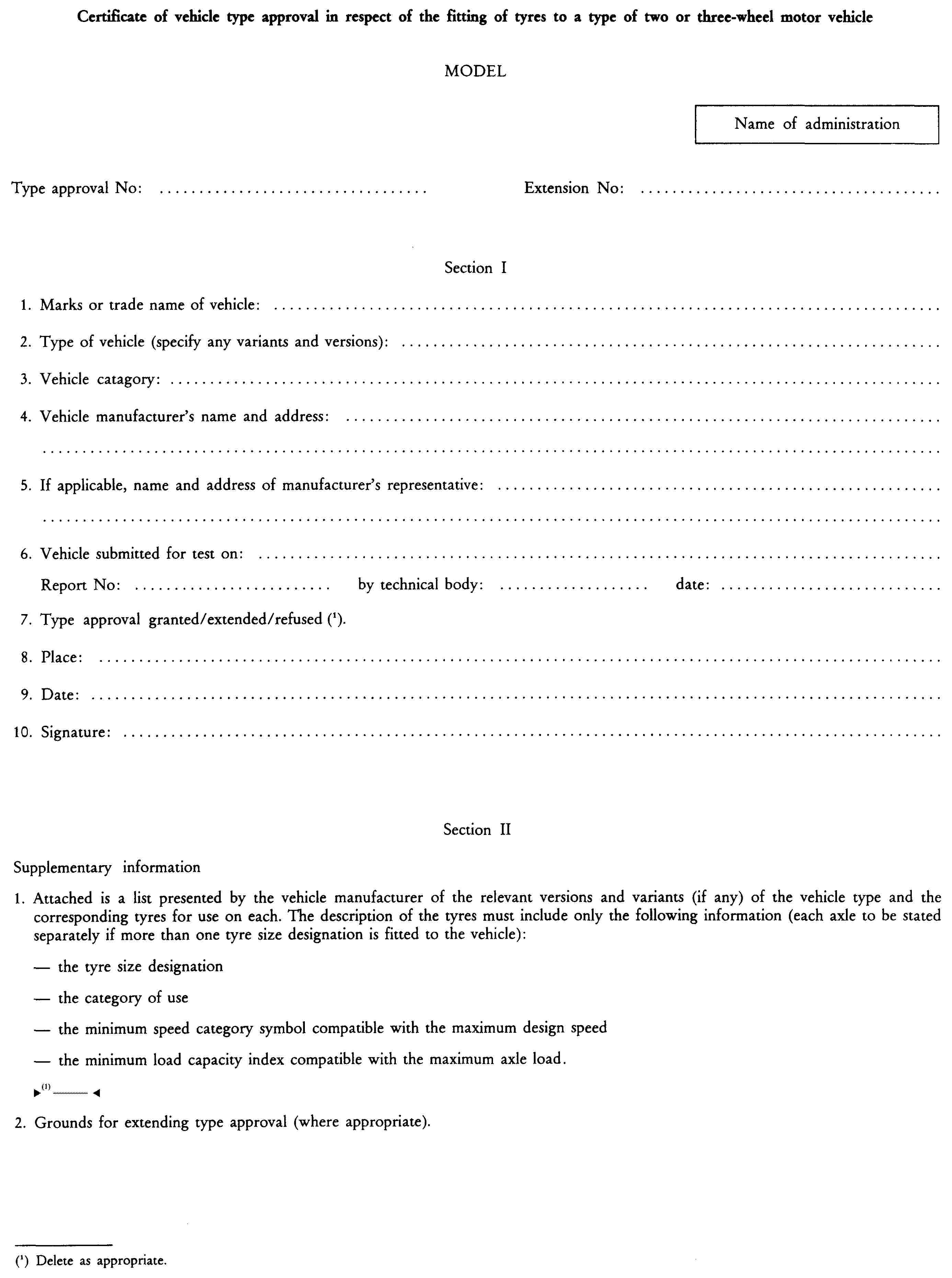
Appendix 2 |
Certificate of vehicle type approval in respect of the fitting of tyres to a type of two or three-wheel motor vehicle |
ANNEX I
ADMINISTRATIVE PROVISIONS FOR THE COMPONENT TYPE APPROVAL OF A TYPE OF TYRE
1. APPLICATION FOR COMPONENT TYPE APPROVAL
|
1.1. |
The application for the component type approval of a type of tyre must give precise details of the type of tyre to which the component type approval mark is to be affixed. |
|
1.2. |
For each type of tyre that application must also give precise details on:
|
|
1.3. |
The application for component type approval shall also be accompanied by sketches or photographs in triplicate which identify the tread pattern and the envelope of the inflated tyre mounted on the measuring rim showing the relevant dimensions (see sections 3.1.1 and 3.1.2 of Annex II) of the tyre type submitted for approval. It shall also be accompanied by the test report issued by an approved test laboratory or by two samples of the tyre type at the discretion of the competent authority. |
|
1.4. |
The tyre manufacturer may request that the EC component type approval be extended also to other types of modified tyres. |
|
1.5. |
This Directive does not apply to new tyres designed only for ‘off-road’ use and marked ‘NHS’ (not for highway service) or for competitions. |
2. MARKINGS
The samples of a type of tyre submitted for component type approval shall bear, in a clearly legible and indelible manner, the applicant's make or trade name and shall include sufficient space for the component type approval mark.
3. COMPONENT TYPE APPROVAL MARK
All tyres conforming to a type that has been component type-approved in compliance with this Directive shall bear the component type-approval mark described in Annex 5 to Directive 92/61/EEC of 30 June 1992 on the type approval of two or three-wheel motor vehicles.
The ‘a’ value defining the dimensions of the rectangle and the digits and letters making up the mark shall not be less than 2 mm.
4. MODIFICATION OF A TYRE TYPE
|
4.1. |
A modification of the tread pattern of a tyre does not require the repetition of tests prescribed in Annex II. |
Appendix 1

Appendix 2

ANNEX II
DEFINITIONS, MARKINGS, AND REQUIREMENTS
1. DEFINITIONS
For the purposes of this chapter:
|
1.1. |
‘type of tyre’ means tyres which basically do not differ from one another in respect of:
|
|
1.2. |
‘tyre structure’ means the technical characteristics of a tyre carcass. A distinction is drawn, in particular, between the following tyre configurations:
|
|
1.3. |
‘bead’ means the part of the tyre the shape and structure of which enables it to fit the rim and hold the tyre on that rim ( 28 ); |
|
1.4. |
‘cords’ means the strands forming the fabric of the plies in the pneumatic tyre (28) ; |
|
1.5. |
‘ply’ means A layer of rubber coated parallel cords (28) ; |
|
1.6. |
‘carcass’ means the part of the tyre other than the tread and the sidewalls which, when inflated, bears the load (28) ; |
|
1.7. |
‘tread’ means that part of the tyre which comes into contact with the ground (28) ; |
|
1.8. |
‘sidewall’ means that part of a tyre lying between the tread and the part intended to be covered by the wheel rim (28) ; |
|
1.9. |
‘tread groove’ means the space between two adjacent ribs or blocks in the tread pattern (28) ; |
|
1.10. |
‘main grooves’ means the wide grooves located in the central zone of the tread; |
|
1.11. |
‘section width (S)’ means the linear distance between the outer edges of the sidewalls of an inflated tyre excluding the protrusions due to markings, embellishments or protective bands or ribs (28) ; |
|
1.12. |
‘overall width’ means the linear distance between the outer edges of the sidewalls of an inflated tyre, including markings, embellishments and protective bands or ribs (28) ; the overall width of tyres the tread width of which is greater than the section width is the width of the tread; |
|
1.13. |
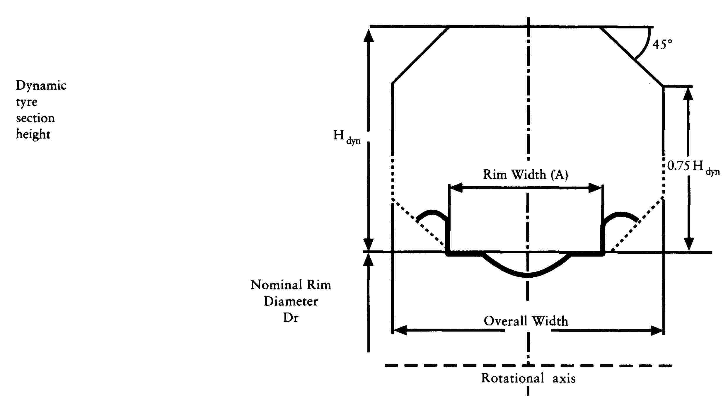
‘section height (H)’ means the distance equalling half the difference beween the outer diameter of the tyre and the nominal rim diameter ( 29 ); |
|
1.14. |
‘nominal aspect ratio (Ra)’ means one hundred times the number obtained by dividing the nominal section height by the nominal section width (S1) both being expressed in the same unit of measurement; |
|
1.15. |
‘outer diameter (D)’ means the overall diameter of an inflated new tyre (29) ; |
|
1.16. |
‘tyre size designation’ means the description containing the following:
|
|
1.17. |
‘nominal rim diameter (d)’ means the diameter of the rim on which a tyre is designed to be mounted ( 30 ); |
|
1.18. |
‘rim’ means the support for either a tyre and inner tube or a tubeless tyre on which the beads of the tyre are seated (30) ; |
|
1.19. |
‘theoretical rim’ means an imaginary rim the width of which would be X times the nominal section width of a tyre. The X value must be specified by the tyre manufacturer; |
|
1.20. |
‘measuring rim’ means the rim on which a tyre must be fitted for dimensional measurement purposes; |
|
1.21. |
‘test rim’ means the rim to which a tyre must be fitted for testing; |
|
1.22. |
‘chunking’ means the breaking away of pieces of rubber from the tyre tread; |
|
1.23. |
‘cord separation’ means parting of the cords from their coating rubber; |
|
1.24. |
‘ply separation’ means the parting of adjacent plies; |
|
1.25. |
‘tread separation’ means the pulling away of the tread from the carcass |
|
1.26. |
‘load-capacity index’ means a figure associated with the maximum permissible load which a tyre can carry at the speed corresponding to its speed symbol according to the operating conditions specified by the manufacturer. Appendix 3 to Annex II certains a list of indices and the corresponding loads; |
|
1.27. |
‘table of load variations as a function of speed’ means the table in Appendix 7 to Annex II stating, by reference to indices of load capacity and of capacity at nominal speed, load variations of a tyre used at speeds other than those corresponding to that indicated by the nominal speed category; |
|
1.28. |
‘speed category’ means
|
|
1.29. |
‘snow tyre’ means a tyre pattern and structure of which are designed primarily to ensure better behaviour than that of normal tyres in mud and fresh snow or slush. The tread pattern of snow tyres generally consists of grooves and/or blocks which are more widely spaced than those of a normal tyre; |
|
1.30. |
‘MST’ (multiservice tyre) means a multi-use tyre, or in other words a tyre suitable for both on-road and off-road use; |
|
1.31. |
‘maximum load rating’ means the maximum mass which a tyre is rated to carry:
|
|||||||||||||||||||||||||||||||||||||
|
1.32. |
‘moped tyre’ means a tyre designed to be fitted on mopeds; |
|
1.33. |
‘motor cycle tyre’ means a tyre designed primarily to be fitted on motor cycles |
|
1.34. |
‘rolling circumference (Cr)’ means the theoretical distance covered by the centre (axis) of the wheel of a vehicle in motion during one complete revolution of the tyre and obtained from the following formula: Cr = f × D, where: D is the outer diameter of the tyre in accordance with the tyre size designation set out in item 3.1.2 in this Annex
|
2. MARKINGS
|
2.1. |
On at least one of their sidewalls, tyres shall bear the following markings:
|
|
2.2. |
Appendix 2 provides an example of layout for the tyre markings. |
|
2.3. |
The markings referred to in 2.1 and the component type approval mark prescribed in Section 3 of Annex I shall be moulded into or onto the tyres. They shall be clearly legible. |
3. REQUIREMENTS RELATING TO TYRES
3.1. Tyre dimensions
|
3.1.1. |
Section width
|
|
3.1.2. |
Tyre outer diameter
|
|
3.1.3. |
Tyre measuring method; The tyre dimensions shall be measured as specified in Appendix 5 to this Annex. |
|
3.1.4. |
Specifications concerning tyre section width;
|
|
3.1.5. |
Specifications concerning the tyre's outer diameter;
|
3.2. Load/speed perfomance test
|
3.2.1. |
The load/speed performance test shall be carried out on a tyre in accordance with the method set out in Appendix 6 to Annex II
|
|
3.2.2. |
After successfully undergoing the load/speed test a tyre shall not exhibit any tread ply or cord separation or any chunking or cord breakage. |
|
3.2.3. |
The outer diameter of the tyre measured at least six hours after the load/speed performance test shall not differ from the outer diameter measured before the test by more than ± 3,5 %. |
|
3.2.4. |
The tyre overall width measured at the end of the load/speed performance test shall not exceed the value set out in Item 3.1.4.2. |
3.3. Dynamic growth of tyres
The tyres referred to in Item 1.1 in Appendix 8 to Annex II which have passed the load/speed performance test required in Item 3.2.1 shall undergo a dynamic growth test, to be carried out in accordance with the practical method set out in the said Appendix.
|
3.4. |
Where a tyre manufacturer produces a range of tyres, it is not necessary to carry out load/speed performance tests and dynamic growth tests on each type of tyre in the range. The option of choosing the least favourable case is left to the discretion of the authorities responsible for component type approval. |
|
3.5. |
A modification of the tread pattern of a tyre is deemed not to necessitate repetition of the test specified in sections 3.2 and 3.3 of this Annex. |
|
3.6. |
Extensions of approval for tyres suitable for speeds over 240 km/h for tyres identified by means of letter code ‘V’ within the size designation (or 270 km/h for tyres identified by means of letter code ‘Z’ within the size designation), with a view to certification for different maximum speeds and/or loads, are permitted, provided that a new test report relating to the new maximum speed and load rating is supplied by the technical service responsible for carrying out tests. Such new load/speed capabilities must be specified in Appendix 2 of Annex I. |
Appendix 1

Explanatory diagram
(see item 1 in this Annex)
Appendix 2
Arrangement of tyre markings
Example of the markings which must appear on type approved types of tyres

|
b |
100/80 B 18 |
53 S |
TUBELESS M + S |
013 |
These markings define a tyre:
— having a nominal section width of 100,
— having a nominal aspect ratio of 80,
— being of bias-belted structure (B),
— having a rim diameter of 457 mm, the code for which is 18,
— having a load capacity of 206 kg, corresponding to load index 53 (see list in appendix 3),
— classified in the speed category S (maximum speed 180 km/h),
— which may be fitted without an inner tube (tubeless),
— being of the snow type (M + S),
— manufactured during week 1 (01) of the year 1993 (3).
The position and order of the markings constituting the tyre designation shall be as follows:
(a) the tyre size designation including the nominal section width, the nominal aspect ratio, the symbol of the structure, where appropriate, and the nominal rim diameter shall be combined as shown in the above example i.e. 100/80 B 18;
(b) the load capacity index and the speed category symbol shall be placed near the tyre size designation. They may either precede or follow this or be located above or below it;
(c) the descriptions ‘TUBELESS’ and ‘REINFORCED’ or ‘REINF’ and ‘M + S’ or ‘M.S.’ or ‘M & S’ and ‘MST’ and/or ‘MOPED’, ‘CICLOMOTORE’ or ‘CYCLOMOTEUR’ may be further away from the dimensional description;
(d) In the case of tyres suitable for speeds above 240 km/h, the letter codes ‘V’ or ‘Z’, as applicable, must be marked in front of the structure marking (e.g. 140/60ZR18). The reference load capacity index and speed category symbol must be marked within parentheses as applicable (see Item 2.1.13 of Annex II).
Appendix 3
List of load-capacity indices and corresponding permissible maximum mass
|
A |
= |
load capacity index |
|
B |
= |
corresponding maximum mass (kg) |
|
A |
B |
|
0 |
45 |
|
1 |
46,2 |
|
2 |
47,5 |
|
3 |
48,7 |
|
4 |
50 |
|
5 |
51,5 |
|
6 |
53 |
|
7 |
54,5 |
|
8 |
56 |
|
9 |
58 |
|
10 |
60 |
|
11 |
61,5 |
|
12 |
63 |
|
13 |
65 |
|
14 |
67 |
|
15 |
69 |
|
16 |
71 |
|
17 |
73 |
|
18 |
75 |
|
19 |
77,5 |
|
20 |
80 |
|
21 |
82,5 |
|
22 |
85 |
|
23 |
87,5 |
|
24 |
90 |
|
25 |
92,5 |
|
26 |
95 |
|
27 |
97,5 |
|
28 |
100 |
|
29 |
103 |
|
30 |
106 |
|
31 |
109 |
|
32 |
112 |
|
33 |
115 |
|
34 |
118 |
|
35 |
121 |
|
36 |
125 |
|
37 |
128 |
|
38 |
132 |
|
39 |
136 |
|
40 |
140 |
|
41 |
145 |
|
42 |
150 |
|
43 |
155 |
|
44 |
160 |
|
45 |
165 |
|
46 |
170 |
|
47 |
175 |
|
48 |
180 |
|
49 |
185 |
|
50 |
190 |
|
51 |
195 |
|
52 |
200 |
|
53 |
206 |
|
54 |
212 |
|
55 |
218 |
|
56 |
224 |
|
57 |
230 |
|
58 |
236 |
|
59 |
243 |
|
60 |
250 |
|
61 |
257 |
|
62 |
265 |
|
63 |
272 |
|
64 |
280 |
|
65 |
290 |
|
66 |
300 |
|
67 |
307 |
|
68 |
315 |
|
69 |
325 |
|
70 |
335 |
|
71 |
345 |
|
72 |
355 |
|
73 |
365 |
|
74 |
375 |
|
75 |
387 |
|
76 |
400 |
|
77 |
412 |
|
78 |
425 |
|
79 |
437 |
|
80 |
450 |
|
81 |
462 |
|
82 |
475 |
|
83 |
487 |
|
84 |
500 |
|
85 |
515 |
|
86 |
530 |
|
87 |
545 |
|
88 |
560 |
|
89 |
580 |
|
90 |
600 |
|
91 |
615 |
|
92 |
630 |
|
93 |
650 |
|
94 |
670 |
|
95 |
690 |
|
96 |
710 |
|
97 |
730 |
|
98 |
750 |
|
99 |
775 |
|
100 |
800 |
|
101 |
825 |
|
102 |
850 |
|
103 |
875 |
|
104 |
900 |
|
105 |
925 |
|
106 |
950 |
|
107 |
975 |
|
108 |
1 000 |
|
109 |
1 030 |
|
110 |
1 060 |
|
111 |
1 090 |
|
112 |
1 120 |
|
113 |
1 150 |
|
114 |
1 180 |
|
115 |
1 215 |
|
116 |
1 250 |
|
117 |
1 285 |
|
118 |
1 320 |
|
119 |
1 360 |
|
120 |
1 400 |
Appendix 4
Marking and dimensions of certain types of tyre
(See Annex II, items 3.1.1.2, 3.1.2.2, 3.1.4.2 and 3.1.5.1)
TABLE 1 A
Moped tyres
Descriptions and rim diameter up to code 12
|
Tyre size designation |
Width of theoretical RIM (code) (A1) |
Overall diameter (mm) |
Nominal (S1) (mm) section width |
Maximum overall width (mm) |
||
|
Dmin |
D |
Dmax |
||||
|
2-12 |
1.35 |
413 |
417 |
426 |
55 |
59 |
|
21/4-12 |
1.50 |
425 |
431 |
441 |
62 |
67 |
|
21/2-8 |
1.75 |
339 |
345 |
356 |
70 |
76 |
|
21/2-9 |
1.75 |
365 |
371 |
382 |
70 |
76 |
|
23/4-9 |
1.75 |
375 |
381 |
393 |
73 |
79 |
|
3-10 |
2.10 |
412 |
418 |
431 |
84 |
91 |
|
3-12 |
2.10 |
463 |
469 |
482 |
84 |
91 |
TABLE 1 B
Motor cycle tyres
Descriptions and rim diameter up to code 12
|
Tyre size designation |
Width of theoretical RIM (code) (A1) |
Overall diameter (mm) |
Nominal (S1) (mm) section width |
Maximum overall width (mm) |
||
|
Dmin |
D |
Dmax |
||||
|
2.50-8 |
1.50 |
328 |
338 |
352 |
65 |
70 |
|
2.50-9 |
354 |
364 |
378 |
|||
|
2.50-10 |
379 |
389 |
403 |
|||
|
2.50-12 |
430 |
440 |
451 |
|||
|
2.75-8 |
1.75 |
338 |
348 |
363 |
71 |
77 |
|
2.75-9 |
364 |
374 |
383 |
|||
|
2.75-10 |
389 |
399 |
408 |
|||
|
2.75-12 |
440 |
450 |
462 |
|||
|
3.00-4 |
2.10 |
241 |
251 |
264 |
80 |
86 |
|
3.00-5 |
266 |
276 |
291 |
|||
|
3.00-6 |
291 |
301 |
314 |
|||
|
3.00-7 |
317 |
327 |
342 |
|||
|
3.00-8 |
352 |
362 |
378 |
|||
|
3.00-9 |
378 |
388 |
401 |
|||
|
3.00-10 |
403 |
413 |
422 |
|||
|
3.00-12 |
454 |
464 |
473 |
|||
|
3.25-8 |
2.50 |
362 |
372 |
386 |
88 |
95 |
|
3.25-9 |
388 |
398 |
412 |
|||
|
3.25-10 |
414 |
424 |
441 |
|||
|
3.25-12 |
465 |
475 |
492 |
|||
|
3.50-4 |
2.50 |
264 |
274 |
291 |
92 |
99 |
|
3.50-5 |
289 |
299 |
316 |
|||
|
3.50-6 |
314 |
324 |
341 |
|||
|
3.50-7 |
340 |
350 |
367 |
|||
|
3.50-8 |
376 |
386 |
397 |
|||
|
3.50-9 |
402 |
412 |
430 |
|||
|
3.50-10 |
427 |
437 |
448 |
|||
|
3.50-12 |
478 |
488 |
506 |
|||
|
4.00-5 |
2.50 |
314 |
326 |
346 |
105 |
113 |
|
4.00-6 |
339 |
351 |
368 |
|||
|
4.00-7 |
365 |
377 |
394 |
|||
|
4.00-8 |
401 |
415 |
427 |
|||
|
4.00-10 |
452 |
466 |
478 |
|||
|
4.00-12 |
505 |
517 |
538 |
|||
|
4.50-6 |
3.00 |
364 |
376 |
398 |
120 |
130 |
|
4.50-7 |
390 |
402 |
424 |
|||
|
4.50-8 |
430 |
442 |
464 |
|||
|
4.50-9 |
456 |
468 |
490 |
|||
|
4.50-10 |
481 |
493 |
515 |
|||
|
4.50-12 |
532 |
544 |
568 |
|||
|
5.00-8 |
3.50 |
453 |
465 |
481 |
134 |
145 |
|
5.00-10 |
504 |
516 |
532 |
|||
|
5.00-12 |
555 |
567 |
583 |
|||
|
6.00-6 |
4.00 |
424 |
436 |
464 |
154 |
166 |
|
6.00-7 |
450 |
462 |
490 |
|||
|
6.00-8 |
494 |
506 |
534 |
|||
|
6.00-9 |
520 |
532 |
562 |
|||
TABLE 2
Motor cycle and moped tyres
Normal profile
|
Tyre size designation |
Width of theoretical RIM (code) (A1) |
Overall diameter (mm) |
Nominal (S1) (mm) section width |
Maximum overall width (mm) |
||||
|
Dmin |
D |
Dmax (1) |
Dmax (2) |
|||||
|
13/4-19 |
1.20 |
582 |
589 |
597 |
605 |
50 |
54 |
58 |
|
2-14 |
1.35 |
461 |
468 |
477 |
484 |
55 |
58 |
63 |
|
2-15 |
486 |
493 |
501 |
509 |
||||
|
2-16 |
511 |
518 |
526 |
534 |
||||
|
2-17 |
537 |
544 |
552 |
560 |
||||
|
2-18 |
562 |
569 |
577 |
585 |
||||
|
2-19 |
588 |
595 |
603 |
611 |
||||
|
2-20 |
613 |
620 |
628 |
636 |
||||
|
2-21 |
638 |
645 |
653 |
661 |
||||
|
2-22 |
663 |
670 |
680 |
686 |
||||
|
21/4-14 |
1.50 |
474 |
482 |
492 |
500 |
62 |
66 |
71 |
|
21/4-15 |
499 |
507 |
517 |
525 |
||||
|
21/4-16 |
524 |
532 |
540 |
550 |
||||
|
21/4-17 |
550 |
558 |
566 |
576 |
||||
|
21/4-18 |
575 |
583 |
591 |
601 |
||||
|
21/4-19 |
601 |
609 |
617 |
627 |
||||
|
21/4-20 |
626 |
634 |
642 |
652 |
||||
|
21/4-21 |
651 |
659 |
667 |
677 |
||||
|
21/4-22 |
677 |
685 |
695 |
703 |
||||
|
21/2-14 |
1.60 |
489 |
498 |
508 |
520 |
68 |
72 |
78 |
|
21/2-15 |
514 |
523 |
533 |
545 |
||||
|
21/2-16 |
539 |
548 |
558 |
570 |
||||
|
2-17 |
565 |
574 |
584 |
596 |
||||
|
21/2-18 |
590 |
599 |
609 |
621 |
||||
|
21/2-19 |
616 |
625 |
635 |
647 |
||||
|
21/2-20 |
641 |
650 |
660 |
672 |
||||
|
21/2-21 |
666 |
675 |
685 |
697 |
||||
|
21/2-22 |
692 |
701 |
711 |
723 |
||||
|
23/4-14 |
1.85 |
499 |
508 |
518 |
530 |
75 |
80 |
86 |
|
23/4-15 |
524 |
533 |
545 |
555 |
||||
|
23/4-16 |
549 |
558 |
568 |
580 |
||||
|
23/4-17 |
575 |
584 |
594 |
606 |
||||
|
23/4-18 |
600 |
609 |
621 |
631 |
||||
|
23/4-19 |
626 |
635 |
645 |
657 |
||||
|
23/4-20 |
651 |
660 |
670 |
682 |
||||
|
23/4-21 |
676 |
685 |
695 |
707 |
||||
|
23/4-22 |
702 |
711 |
721 |
733 |
||||
|
3-16 |
1.85 |
560 |
570 |
582 |
594 |
81 |
86 |
93 |
|
3-17 |
586 |
596 |
608 |
620 |
||||
|
3-18 |
611 |
621 |
633 |
645 |
||||
|
3-19 |
637 |
647 |
659 |
671 |
||||
|
31/4-16 |
2.15 |
575 |
586 |
598 |
614 |
89 |
94 |
102 |
|
31/4-17 |
601 |
612 |
624 |
640 |
||||
|
31/4-18 |
626 |
637 |
651 |
665 |
||||
|
31/4-19 |
652 |
663 |
675 |
691 |
||||
|
(1) Tyres for normal use. (2) Multiservice and snow tyres. |
||||||||
TABLE 3
Motor cycle tyres
Normal profile
|
Tyre size designation |
Width of theoretical RIM (code) (A1) |
Overall diameter (mm) |
Nominal (S1)(mm)section width |
Maximum overall width (mm) |
|||||
|
Dmin |
D |
Dmax (1) |
Dmax (2) |
||||||
|
2.00-14 |
1.20 |
460 |
466 |
478 |
52 |
57 |
60 |
65 |
|
|
2.00-15 |
485 |
491 |
503 |
||||||
|
2.00-16 |
510 |
516 |
528 |
||||||
|
2.00-17 |
536 |
542 |
554 |
||||||
|
2.00-18 |
561 |
567 |
579 |
||||||
|
2.00-19 |
587 |
593 |
605 |
||||||
|
2.25-14 |
1.60 |
474 |
480 |
492 |
496 |
61 |
67 |
70 |
75 |
|
2.25-15 |
499 |
505 |
517 |
521 |
|||||
|
2.25-16 |
524 |
530 |
542 |
546 |
|||||
|
2.25-17 |
550 |
556 |
568 |
572 |
|||||
|
2.25-18 |
575 |
581 |
593 |
597 |
|||||
|
2.25-19 |
601 |
607 |
619 |
623 |
|||||
|
2.50-14 |
1.60 |
486 |
492 |
506 |
508 |
65 |
72 |
75 |
79 |
|
2.50-15 |
511 |
517 |
531 |
533 |
|||||
|
2.50-16 |
536 |
542 |
556 |
558 |
|||||
|
2.50-17 |
562 |
568 |
582 |
584 |
|||||
|
2.50-18 |
587 |
593 |
607 |
609 |
|||||
|
2.50-19 |
613 |
619 |
633 |
635 |
|||||
|
2.50-21 |
663 |
669 |
683 |
685 |
|||||
|
2.75-14 |
1.85 |
505 |
512 |
524 |
530 |
75 |
83 |
86 |
91 |
|
2.75-15 |
530 |
537 |
549 |
555 |
|||||
|
2.75-16 |
555 |
562 |
574 |
580 |
|||||
|
2.75-17 |
581 |
588 |
600 |
606 |
|||||
|
2.75-18 |
606 |
613 |
625 |
631 |
|||||
|
2.75-19 |
632 |
639 |
651 |
657 |
|||||
|
2.75-21 |
682 |
689 |
701 |
707 |
|||||
|
3.00-14 |
1.85 |
519 |
526 |
540 |
546 |
80 |
88 |
92 |
97 |
|
3.00-15 |
546 |
551 |
565 |
571 |
|||||
|
3.00-16 |
569 |
576 |
590 |
596 |
|||||
|
3.00-17 |
595 |
602 |
616 |
622 |
|||||
|
3.00-18 |
618 |
627 |
641 |
647 |
|||||
|
3.00-19 |
644 |
653 |
667 |
673 |
|||||
|
3.00-21 |
694 |
703 |
717 |
723 |
|||||
|
3.00-23 |
747 |
754 |
768 |
774 |
|||||
|
3.25-14 |
2.15 |
531 |
538 |
552 |
560 |
89 |
98 |
102 |
108 |
|
3.25-15 |
556 |
563 |
577 |
585 |
|||||
|
3.25-16 |
581 |
588 |
602 |
610 |
|||||
|
3.25-17 |
607 |
614 |
628 |
636 |
|||||
|
3.25-18 |
630 |
639 |
653 |
661 |
|||||
|
3.25-19 |
656 |
665 |
679 |
687 |
|||||
|
3.25-21 |
708 |
715 |
729 |
737 |
|||||
|
3.50-14 |
2.15 |
539 |
548 |
564 |
572 |
93 |
102 |
107 |
113 |
|
3.50-15 |
564 |
573 |
589 |
597 |
|||||
|
3.50-16 |
591 |
598 |
614 |
622 |
|||||
|
3.50-17 |
617 |
624 |
640 |
648 |
|||||
|
3.50-18 |
640 |
649 |
665 |
673 |
|||||
|
3.50-19 |
666 |
675 |
691 |
699 |
|||||
|
3.50-21 |
716 |
725 |
741 |
749 |
|||||
|
3.75-16 |
2.15 |
601 |
610 |
626 |
634 |
99 |
109 |
114 |
121 |
|
3.75-17 |
627 |
636 |
652 |
660 |
|||||
|
3.75-18 |
652 |
661 |
677 |
685 |
|||||
|
3.75-19 |
678 |
687 |
703 |
711 |
|||||
|
4.00-16 |
2.50 |
611 |
620 |
638 |
646 |
108 |
119 |
124 |
130 |
|
4.00-17 |
637 |
646 |
664 |
672 |
|||||
|
4.00-18 |
662 |
671 |
689 |
697 |
|||||
|
4.00-19 |
688 |
697 |
715 |
723 |
|||||
|
4.25-16 |
2.50 |
623 |
632 |
650 |
660 |
112 |
123 |
129 |
137 |
|
4.25-17 |
649 |
658 |
676 |
686 |
|||||
|
4.25-18 |
674 |
683 |
701 |
711 |
|||||
|
4.25-19 |
700 |
709 |
727 |
737 |
|||||
|
4.50-16 |
2.75 |
631 |
640 |
658 |
665 |
123 |
135 |
141 |
142 |
|
4.50-17 |
657 |
666 |
684 |
694 |
|||||
|
4.50-18 |
684 |
691 |
709 |
719 |
|||||
|
4.50-19 |
707 |
717 |
734 |
745 |
|||||
|
5.00-16 |
3.00 |
657 |
666 |
686 |
698 |
129 |
142 |
148 |
157 |
|
5.00-17 |
683 |
692 |
710 |
724 |
|||||
|
5.00-18 |
708 |
717 |
735 |
749 |
|||||
|
5.00-19 |
734 |
743 |
761 |
775 |
|||||
|
(1) Tyres for normal on-road use (2) Special-purpose and snow tyres (3) Tyres for normal on-road use up to and including speed rating P (4) Tyres for normal on-road use beyond speed rating P and snow tyres (5) Special-purpose tyres |
|||||||||
TABLE 4
Motor cycle tyres
Low profile
|
Tyre size designation |
Width of theoretical rim (code) (A1) |
Overall diameter (mm) |
Nominal (S1) (mm) section width |
Maximum overall width (mm) |
|||||
|
Dmin |
D |
Dmax (1) |
Dmax (2) |
||||||
|
3.60-18 |
2.15 |
605 |
615 |
628 |
633 |
93 |
102 |
108 |
113 |
|
3.60-19 |
631 |
641 |
653 |
658 |
|||||
|
4.10-18 |
2.50 |
629 |
641 |
654 |
663 |
108 |
119 |
124 |
130 |
|
4.10-19 |
655 |
667 |
679 |
688 |
|||||
|
5.10-16 |
3.00 |
615 |
625 |
643 |
651 |
129 |
142 |
150 |
157 |
|
5.10-17 |
641 |
651 |
670 |
677 |
|||||
|
5.10-18 |
666 |
676 |
694 |
702 |
|||||
|
4.25/85-18 |
2.50 |
649 |
659 |
673 |
683 |
112 |
123 |
129 |
137 |
|
4.60-16 |
2.75 |
594 |
604 |
619 |
628 |
117 |
129 |
136 |
142 |
|
4.60-17 |
619 |
630 |
642 |
654 |
|||||
|
4.60-18 |
644 |
654 |
670 |
678 |
|||||
|
(1) Tyres for normal on-road use (2) Special-purpose and snow tyres (3) Tyres for normal on-road use up to and including speed rating P (4) Tyres for normal on-road use beyond speed rating P and snow tyres (5) Special-purpose tyres |
|||||||||
TABLE 5
Tyres for motorcycle derivatives
|
Tyre size designation |
Width of theoretical rim (code) (A1) |
Overall diameter (mm) |
Nominal (S1) (mm) section width |
Maximum overall width (mm) |
||
|
Dmin |
D |
Dmax |
||||
|
3.00-8C |
2.10 |
359 |
369 |
379 |
80 |
86 |
|
3.00-10C |
410 |
420 |
430 |
|||
|
3.00-12C |
459 |
471 |
479 |
|||
|
3.50-8C |
2.50 |
376 |
386 |
401 |
92 |
99 |
|
3.50-10C |
427 |
437 |
452 |
|||
|
3.50-12C |
478 |
488 |
513 |
|||
|
4.00-8C |
3.00 |
405 |
415 |
427 |
108 |
117 |
|
4.00-10C |
456 |
466 |
478 |
|||
|
4.00-12C |
507 |
517 |
529 |
|||
|
4.50-8C |
3.50 |
429 |
439 |
453 |
125 |
135 |
|
4.50-10C |
480 |
490 |
504 |
|||
|
4.50-12C |
531 |
541 |
555 |
|||
|
5.00-8C |
3.50 |
455 |
465 |
481 |
134 |
145 |
|
5.00-10C |
506 |
516 |
532 |
|||
|
5.00-12C |
555 |
567 |
581 |
|||
TABLE 6
Low-pressure motor cycle tyres
|
Tyre size designation |
Width of theoretical rim (code) (A1) |
Overall diameter (mm) |
Nominal (S1) (mm) section width |
Maximum overall width (mm) |
||
|
Dmin |
D |
Dmax |
||||
|
5.4-6 |
4.00 |
373 |
379 |
395 |
135 |
146 |
|
5.4-10 |
474 |
481 |
497 |
|||
|
5.4-12 |
525 |
532 |
547 |
|||
|
5.4-14 |
576 |
582 |
598 |
|||
|
5.4-16 |
626 |
633 |
649 |
|||
|
6.7-10 |
5.00 |
532 |
541 |
561 |
170 |
184 |
|
6.7-12 |
583 |
592 |
612 |
|||
|
6.7-14 |
633 |
642 |
662 |
|||
TABLE 7
Motor cycle tyres
Descriptions and dimensions of American tyres
|
Tyre size designation |
Width of theoretical rim (code) (A1) |
Overall diameter (mm) |
Nominal (S1) (mm) section width |
Maximum overall width (mm) |
||
|
Dmin |
D |
Dmax |
||||
|
MH90-21 |
1.85 |
682 |
686 |
700 |
80 |
89 |
|
MJ90-18 |
2.15 |
620 |
625 |
640 |
89 |
99 |
|
MJ90-19 |
2.15 |
645 |
650 |
665 |
||
|
ML90-18 |
2.15 |
629 |
634 |
650 |
93 |
103 |
|
ML90-19 |
2.15 |
654 |
659 |
675 |
||
|
MM90-19 |
2.15 |
663 |
669 |
685 |
95 |
106 |
|
MN90-18 |
2.15 |
656 |
662 |
681 |
104 |
116 |
|
MP90-18 |
2.15 |
667 |
673 |
692 |
108 |
120 |
|
MR90-18 |
2.15 |
680 |
687 |
708 |
114 |
127 |
|
MS90-17 |
2.50 |
660 |
667 |
688 |
121 |
134 |
|
MT90-16 |
3.00 |
642 |
650 |
672 |
130 |
144 |
|
MT90-17 |
3.00 |
668 |
675 |
697 |
||
|
MU90-15M/C |
3.50 |
634 |
642 |
665 |
142 |
158 |
|
MU90-16 |
3.50 |
659 |
667 |
690 |
||
|
MV90-15M/C |
3.50 |
643 |
651 |
675 |
150 |
172 |
|
MP85-18 |
2.15 |
654 |
660 |
679 |
108 |
120 |
|
MR85-16 |
2.15 |
617 |
623 |
643 |
114 |
127 |
|
MS85-18 |
2.50 |
675 |
682 |
702 |
121 |
134 |
|
MT85-18 |
3.00 |
681 |
688 |
709 |
130 |
144 |
|
MV85-15M/C |
3.50 |
627 |
635 |
658 |
150 |
172 |
Appendix 5
Method of measuring tyre dimensions
|
1. |
The tyre is fitted to the measuring rim and inflated to the pressure ( 31 ) specified by its manufacturer. |
|
2. |
The tyre mounted on its rim is left at ambient laboratory temperature for at least 24 hours. |
|
3. |
The pressure is reset at the value specified in Item 1. |
|
4. |
The overall width is measured by means of a calliper gauge at six equally spaced points, account being taken of the thickness of the ribs or bands. The highest measurement thus obtained shall be retained as the overall width. |
|
5. |
The outer diameter is determined as follows: the maximum circumference is measured and the figure thus obtained is divided by π (3,1416). |
Appendix 6
Procedure for testing load/speed performance
1. TYRE PREPARATION
|
1.1. |
A new tyre shall be fitted to the test rim identified by the manufacturer. |
|
1.2. |
It shall be inflated to the appropriate pressure as set out in the following table:
Other types of tyre shall be inflated to the pressure quoted by their manufacturer. |
|||||||||||||||||||||||||||||||||||||||||||||||||||||||||||||||||
|
1.3. |
The tyre manufacturer may request, giving reasons, the use of an inflation pressure differing from those listed in section 1.2. In such a case the tyre is inflated to that pressure (see item 1.12.13 in Annex I). |
|
1.4. |
The wheel/tyre combination shall be stored at the temperature of the test chamber for at least three hours. |
|
1.5. |
The tyre pressure shall be brought to that specified in Items 1.2 or 1.3. |
2. TEST SEQUENCE
|
2.1. |
The tyre/wheel combination shall be fitted to a test spindle and pressed against the outer surface of a smooth flywheel having a diameter of 1,7 m ± 1 % or 2,0 m ± 1 %. |
|
2.2. |
A load which is equal to 65 % of the following shall be applied to the test spindle:
|
|
2.3. |
Throughout the test the tyre pressure shall not be reset and the test load shall be held constant. |
|
2.4. |
During the test the temperature in the test room shall be kept at between 20 and 30 oC or at a higher temperature if so accepted by the manufacturer. |
|
2.5. |
The test shall proceed uninterrupted, in accordance with the following criteria:
|
|
2.6. |
However, if a second test is performed to assess the top performances of tyres suitable for speeds above 240 km/h, the procedure shall be as follows:
|
3. EQUIVALENT TEST METHODS
If a test method other than that described in Item 2 is used, its equivalence shall be demonstrated.
Appendix 7
Variation of load capacity as a function of speed
|
Speed (km/h) |
Variation in load carrying capacity (%) |
|||||||||
|
Moped |
rim diameter code ≤ 12 |
rim diameter code ≥ 13 |
||||||||
|
speed symbol |
speed symbol |
|||||||||
|
B |
J |
K |
L |
J |
K |
L |
M |
N |
P and above |
|
|
30 |
+ 30 |
+ 30 |
+ 30 |
+ 30 |
+ 30 |
+ 30 |
+ 30 |
+ 30 |
+ 30 |
+ 30 |
|
50 |
0 |
+ 30 |
+ 30 |
+ 30 |
+ 30 |
+ 30 |
+ 30 |
+ 30 |
+ 30 |
+ 30 |
|
60 |
+ 23 |
+ 23 |
+ 23 |
+ 23 |
+ 23 |
+ 23 |
+ 23 |
+ 23 |
+ 23 |
|
|
70 |
+ 16 |
+ 16 |
+ 16 |
+ 16 |
+ 16 |
+ 16 |
+ 16 |
+ 16 |
+ 16 |
|
|
80 |
+ 10 |
+ 10 |
+ 10 |
+ 10 |
+ 10 |
+ 10 |
+ 10 |
+ 10 |
+ 14 |
|
|
90 |
+ 5 |
+ 5 |
+ 7,5 |
+ 5 |
+ 5 |
+ 7,5 |
+ 7,5 |
+ 7,5 |
+ 12 |
|
|
100 |
0 |
0 |
+ 5 |
0 |
0 |
+ 5 |
+ 5 |
+ 5 |
+ 10 |
|
|
110 |
- 7 |
0 |
+ 2,5 |
0 |
+ 2,5 |
+ 2,5 |
+ 2,5 |
+ 8 |
||
|
120 |
- 15 |
- 6 |
0 |
0 |
0 |
0 |
+ 6 |
|||
|
130 |
-25 |
-12 |
-5 |
0 |
0 |
+ 4 |
||||
|
140 |
0 |
0 |
||||||||
Appendix 8
Method for determining the dynamic growth of tyres
1. SCOPE AND EXTENT
|
1.1. |
This test method shall apply to motorcycle tyres of the types referred to in Item 3.4.1 of this Appendix. |
|
1.2. |
It is intended to determine the maximum growth of the tyre which is due to the effect of the centrifugal force at the maximum permissible speed. |
2. DESCRIPTION OF TEST PROCEDURE
|
2.1. |
The test axle and the rim shall be checked in order to ensure that radial eccentricity is less than ± 0,5 mm and that lateral displacement is less than ± 0,5 mm when measured at the outer periphery of the bead seat of the wheel. |
|
2.2. |
Contour-outline device Any device (projection grid camera, spotlights and others) enabling the outer contour of the cross section of the tyre to be outlined distinctly or to establish an enveloping curve, at right angles to the equator of the tyre at the point of maximum tread deformation. This device shall reduce any deformation to a minimum and ensure a constant (known) ratio (K) between the contour plotted and the acutual diemensions of the tyre. This device will enable the tyre contour to be determined in relation to the wheel axis. |
3. EXECUTION OF TEST
|
3.1. |
During the test the temperature in the test room shall be held between 20 oC and 30 oC or at a higher temperature if so accepted by the tyre manufacturer. |
|
3.2. |
The tyres to be tested must have undergone the load/speed performance test in accordance with Appendix 6 without any faults having emerged. |
|
3.3. |
The tyre to be tested shall be fitted to a wheel the rim of which conforms to the applicable standard. |
|
3.4. |
The tyre inflation pressure (test inflation pressure) shall be adjusted to the values indicated in Item 3.4.1.
|
||||||||||||||||
|
3.5. |
The wheel/tyre combination shall be stored at the temperature of the test room for at least three hours. |
|
3.6. |
Following that period of storage the inflation pressure shall be corrected to the value laid down in Item 3.4.1. |
|
3.7. |
The wheel/tyre combination shall be mounted on the test axle and checked to ensure that it turns freely. The tyre may be rotated by a motor acting on the test axle or else via pressure against a test drum. |
|
3.8. |
The entire assembly shall be accelerated without interruption in order to achieve, within five minutes, the maximum speed capability of the tyre. |
|
3.9. |
The contour-outline device shall be installed, care being taken to ensure that it is at right angles to the (direction of) rotation of the tread of the tyre being tested. |
|
3.10. |
A check shall be made that the peripheral speed of the tread surface is equal to the maximum speed capability of the tyre ± 2 %. The equipment shall be kept at a constant speed for five minutes at least and then the cross section of the tyre shall be traced in the area of maximum deformation or a check should be made that the tyre does not exceed the enveloping curve. |
4. ASSESSMENT OF RESULTS
|
4.1. |
The envelope of the tyre/wheel assembly shall be as in the example below.
With reference to items 3.1.4 and 3.1.5 in this Annex, the limit values for the envelope outline are laid down as follows:
|
||||||||||||||||
|
4.2. |
The tyre contour deformation at maximum speed shall not go beyond the envelope outline when related to the tyre axes. |
|
4.3. |
No other test is carried out on the tyre. |
5. EQUIVALENT TEST METHODS
If a method other than that described in item 2 is used its equivalence shall be demonstrated.
ANNEX III
REQUIREMENTS FOR VEHICLES WITH REGARD TO THE FITTING OF THEIR TYRES
1. GENERAL
|
1.1. |
Subject to the provisions of section 2, every tyre fitted to a vehicle, including any spare, shall be type-approved in accordance with the provisions of this Directive. |
|
1.2. |
Tyre Fitment
|
|
1.3. |
Load capacity
|
|
1.4. |
Speed capability
|
2. SPECIAL CASES
|
2.1. |
Tyres which have been component type approved according to Directive 92/23/EEC may also be fitted to motorcycles with side-car, three-wheel mopeds, tricycles and quadricycles. |
|
2.2. |
Motorcycle tyres may also be fitted to mopeds. |
|
2.3. |
In the case of a vehicle which is fitted with tyres which are not motorcycle tyres, passenger car tyres or commercial vehicle tyres, due to special conditions of use (e.g. agricultural tyres, industrial truck tyres, all terrain vehicle tyres), the requirements of Annex II do not apply, provided that the approval authority is satisfied that the tyres fitted are suitable for the operating conditions of the vehicle. |
|
2.4. |
Tyres fitted to low performance mopeds as defined in the note set out in Annex I to Directive 92/61/EEC on the type approval of two or three-wheel motor vehicles may be of a different type from those covered by the requirements of this Chapter, owing to special conditions of use, provided that the authority responsible for vehicle type approval receives an assurance that the tyres fitted are appropriate to the conditions of use of the vehicle. |
Appendix 1

Appendix 2
CHAPTER 2
LIGHTING AND LIGHT-SIGNALLING DEVICES OF TWO OR THREE-WHEEL MOTOR VEHICLES
LIST OF ANNEXES
|
ANNEX I |
General requirements applying to the component type-approval of a type of lighting and light-signalling device for two or three-wheel motor vehicles |
|
Appendix 1 |
Colours of light emitted — Trichromatic coordinates |
|
Appendix 2 |
Examples of arrangements of approval marks |
|
ANNEX II |
Requirements concerning the component type-approval of front position (side) lamps, rear lamps, stop lamps, direction indicator lamps, rear registration-plate illuminating device, front fog lamps, rear fog lamps, reversing lamps and retro-reflectors fitted to two or three-wheel motor vehicles |
|
Appendix 1 |
Minimum horizontal (H) and vertical (V) angles of spatial light distribution |
|
Appendix 2 |
Photometric measurements |
|
Appendix 3 |
Photometric measurements of the rear registration-plate illuminating device |
|
Appendix 4 |
Information document |
|
Appendix 5 |
Component type-approval certificate |
|
ANNEX III |
Requirements relating to the component type-approval of devices (headlamps) using incandescent or halogen filament lamps emitting a passing and/or driving beam fitted to two or three-wheel motor vehicles |
|
ANNEX III-A |
Headlamps for mopeds |
|
Appendix 1 |
Photometric tests on headlamps equipped with category S3 and S4 lamps |
|
Appendix 2 |
Photometric tests on headlamps equipped with category HS2 halogen lamps |
|
Appendix 3 |
Information document in respect of a type of headlamp intended for mopeds |
|
Appendix 4 |
Component type-approval certificate in respect of a type of headlamp intended for mopeds |
|
ANNEX III-B |
Headlamps for motorcycles and tricycles emitting a symmetrical passing beam and a driving beam by means of filament lamps |
|
Appendix 1 |
Photometric tests |
|
Appendix 2 |
Test on the stability of the photometric behaviour of headlamps in operation |
|
Appendix 3 |
Requirements for lamps incorporating lenses of plastic material and testing of lens or material samples and of complete lamps |
|
Appendix 4 |
Information document in respect of a type of headlamp fitted with filament lamps, emitting a symmetrical passing beam and a driving beam and intended to be fitted to motorcycles and tricycles |
|
Appendix 5 |
Component type-approval certificate in respect of a type of headlamp fitted with filament lamps, emitting a symmetrical passing beam and a driving beam and intended for motorcycles and tricycles |
|
ANNEX III-C |
Headlamps for motorcycles and tricycles emitting an asymmetrical passing beam and a driving beam and fitted with halogen filament lamps (HS1 lamps) or filament lamps of category R2 |
|
Appendix 1 |
Measuring screen |
|
Appendix 2 |
Test on the stability of the photometric performance of headlamps in operation |
|
Appendix 3 |
Requirements for lamps incorporating lenses of plastic material and testing of lens or material samples and of complete lamps |
|
Appendix 4 |
Information document in respect of a type of headlamp fitted with halogen filament lamps (HS1 lamps) or filament lamps of category R2, emitting an asymmetrical passing beam and a driving beam and intended to be fitted to motorcycles and tricycles |
|
Appendix 5 |
Component type-approval certificate in respect of a type of headlamp fitted with halogen filament lamps, (HS1 lamps) or filament lamps of category R2, emitting an asymmetrical passing beam and a driving beam and intended to be fitted to motorcycles and tricycles |
|
ANNEX III-D |
Headlamps for motorcycles and tricycles emitting an asymmetrical passing beam and a driving beam and fitted with halogen filament lamps other than HS1 lamps |
|
Appendix 1 |
Measuring screen |
|
Appendix 2 |
Tests on the stability of the photometric performance of headlamps in operation |
|
Appendix 3 |
Requirements for lamps incorporating lenses of plastic material and testing of lens or material samples and of complete lamps |
|
Appendix 4 |
Information document in respect of a type of headlamp fitted with halogen filament lamps, emitting an asymmetrical passing beam and a driving beam and intended to be fitted to motorcycles and tricycles |
|
Appendix 5 |
Component type-approval certificate in respect of a type of headlamp fitted with halogen filament lamps, emitting an asymmetrical passing beam and a driving beam and intended to be fitted to motorcycles and tricycles |
|
ANNEX IV |
Incandescent lamps intended for use in component type-approved lamps for mopeds, motorcycles and tricycles |
|
Appendices 1 to 22 |
(See Annex IV) |
|
Appendix 23 |
Example of the arrangement of the approval mark |
|
Appendix 24 |
Luminous centre and shapes of lamp filaments |
ANNEX I
GENERAL REQUIREMENTS APPLYING TO THE COMPONENT TYPE-APPROVAL OF A TYPE OF LIGHTING AND LIGHT-SIGNALLING DEVICE FOR TWO OR THREE-WHEEL MOTOR VEHICLES
|
1. |
For the purposes of this Chapter: ‘type of device’ means devices which do not differ among themselves in such essential respects as the following:
|
|
2. |
APPLICATION FOR THE COMPONENT TYPE-APPROVAL OF A TYPE OF DEVICE
|
|
3. |
ADDITIONAL REQUIREMENTS CONCERNING THE MARKING OF AND MARKS ON DEVICES
|
|
4. |
COMPONENT TYPE-APPROVAL OF A DEVICE
|
|
5. |
MINIMUM REQUIREMENTS FOR CONFORMITY OF PRODUCTION CONTROL PROCEDURES 5.1. General
5.2. Minimum requirements for verification of conformity by the manufacturer For each type of device the holder of the approval mark must carry out at least the following tests at appropriate intervals. The tests must be carried out in accordance with the provisions of this Directive. If any sampling shows non-conformity with regard to the type of test concerned, further samples are taken and tested. The manufacturer must take steps to ensure the conformity of the production concerned. 5.2.1. Nature of tests Tests of conformity to this Directive must cover the photometric and colorimetric characteristics for headlamps of motorcycles and tricycles and the verification of the change in vertical position of the cut-off line unde the influence of heat. 5.2.2. Methods used in tests
5.2.3. Nature of sampling Samples of devices are selected at random from the production of a uniform batch. A uniform batch means a set of devices of the same type, defined according to the production methods of the manufacturer. The assessment must in general cover series production from individual factories. However, a manufacturer may group together records concerning the same type from several factories, provided these operate under the same quality system and quality management. 5.2.4. Measured and recorded photometric and colorimetric characteristics The sampled device is subjected to photometric measurements at the points provided for in the relevant Annexes unless otherwise prescribed. The trichromatic coordinates must be complied with. 5.2.5. Criteria governing acceptability The manufacturer is responsible for carrying out a statistical study of the test results and for defining, in agreement with the competent authority, criteria governing the acceptability of his products, in order to meet the specifications laid down for the verification of conformity of products in Annex VI to Directive 92/61/EEC. The criteria governing the acceptability must be such that, with a confidence level of 95 %, the minimum probability of passing a spot check in accordance with section 6 (first sampling) would be 0,95. |
|
6. |
MINIMUM REQUIREMENTS FOR SAMPLING BY AN INSPECTOR 6.1. General
6.2. First sampling In the first sampling four devices are selected at random. The first sample of two is marked A, the second sample of two is marked B.
6.3. Repeated sampling In the cases of A3, B2, B3 a repeated sampling, third sample C of two devices and fourth sample D of two special warning lamps, selected from stock manufactured after alignment, is necessary within two months following the notification.
Figure 1 |
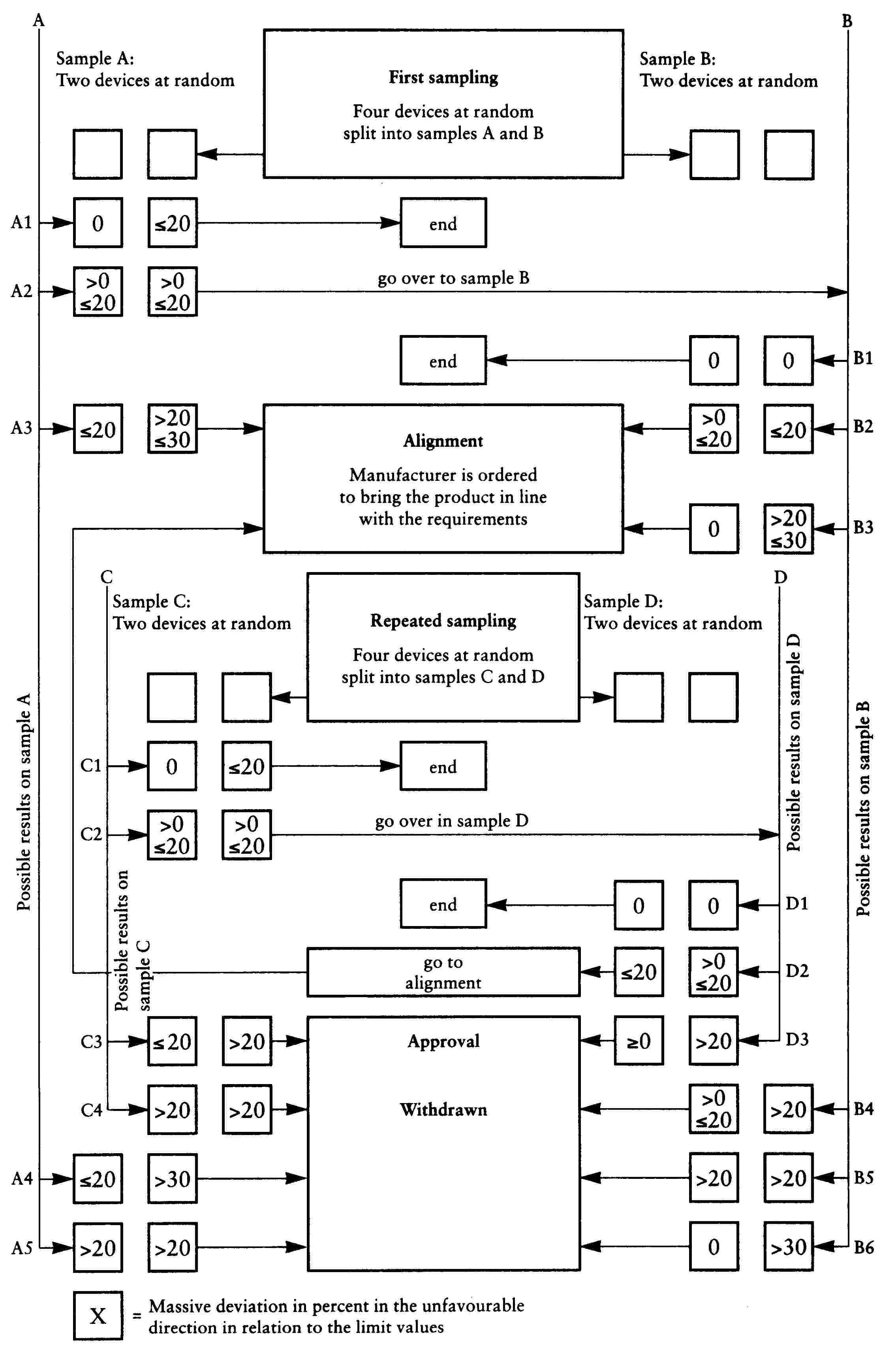
Appendix 1
Colours of Light emitted
Trichomatic co-ordinates
|
RED: |
limit towards yellow: |
y ≤ 0,335 |
|
limit towards purple: |
z ≤ 0,008 |
|
|
WHITE: |
limit towards blue: |
x ≥0,310 |
|
limit towards yellow: |
x ≤ 0,500 |
|
|
limit towards green: |
y ≤ 0,150 + 0,640 × |
|
|
limit towards green: |
y ≤ 0,440 |
|
|
limit towards purple: |
y ≥ 0,050 + 0,750 × |
|
|
limit towards red: |
y ≥ 0,382 |
|
|
AMBER: |
limit towards yellow: |
y ≤ 0,429 |
|
limit towards red: |
y ≥ 0,398 |
|
|
limit towards white: |
z ≤ 0,007 |
For verifying the limits above, a source of light at a colour temperature of 2 856 K (illuminant A of the International Commission on Illumination (CIE)), in combination with appropriate filters, may be used.
For retro-reflectors the device is illuminated by CIE standard illuminant A, with an angle of divergence of 1/3o and an illumination angle V = H = 0o, or, if this produces a colourless surface reflection, an angle V = ± 5o, H = 0o, the trichomatic co-ordinates of the reflected luminous flux must be within the limits above.
Appendix 2
Examples of arrangements of approval marks

Figure 1
A device bearing the EC component type-approval mark shown above is a direction indicator of category 11 approved in the Netherlands (e4) under the number 00243. The first two digits of the approval number indicate that the approval was granted in accordance with the requirements of Annex II to this Directive in its original version.
For a direction indicator, the arrow indicates that the luminous distribution is asymmetrical in a horizontal plane and that the photometric values required are satisfied up to an angle of 80o to the right, the device being seen in the opposite sense of the light emitted. The example shows a direction indicator mounted on the right-hand side of the vehicle.
Simplified marking of grouped, combined or reciprocally incorporated lamps when two or more lamps are part of the same assembly.

Figure 1a
(The vertical and horizontal lines schematize the shape of the light-signalling device. These are not part of the approval mark.)
Note:
These three examples of approval marks (models A, B and C) represent three possible variables for the marking of a lighting device when two or more lamps are part of the same assembly of grouped, combined or reciprocally incorporated lamps.
They indicate that the device was approved in the Netherlands (e4) under approval number 3333 and comprises:
— a retro-reflector of Class 1, approved in accordance with Directive 76/757/EEC in its original version;
— a red rear-position (side) lamp (R) approved in accordance with Annex II to this Directive in its original version;
— a rear fog-lamp (F) approved in accordance with Directive 77/538/EEC in its original version;
— a reversing lamp (AR) approved in accordance with Directive 77/539/EEC in its original version;
— a stop-lamp (S) approved in accordance with Annex II to this Directive in its original version.
Example of EC component type-approval mark
|
|
|
|
|
|


The retro-reflector bearing the EC component type-approval mark shown above is a Class 1 reflector approved in the Netherlands (4) under the number 216 in accordance with Directive 76/757/EEC; the requirements for retro-reflectors in section 9.1 of Annex II to this Directive apply where a ≥ 4 mm.

Figure 2
The headlamp bearing the above EC component type-approval mark was approved in the Netherlands (e4) pursuant to Annex III-A to this Directive in its original version, under approval number 00243. The first two digits of the approval number indicate that the approval was granted in accordance with the requirements of this Directive in its original version.

Figure 3
The headlamp bearing the above EC component type-approval mark is a headlamp meeting the requirements of Annex III-B to this Directive in its original version and is designed for right-hand traffic only.
|
|
|
|
The headlamp bearing the above EC component type-approval mark is a headlamp meeting the requirements of Annex III-B to this Directive in its original version and is designed: |
|
|
For left-hand traffic only. |
For both traffic systems by means of an appropriate adjustment of the setting of the optical unit or the lamp on the vehicle. |


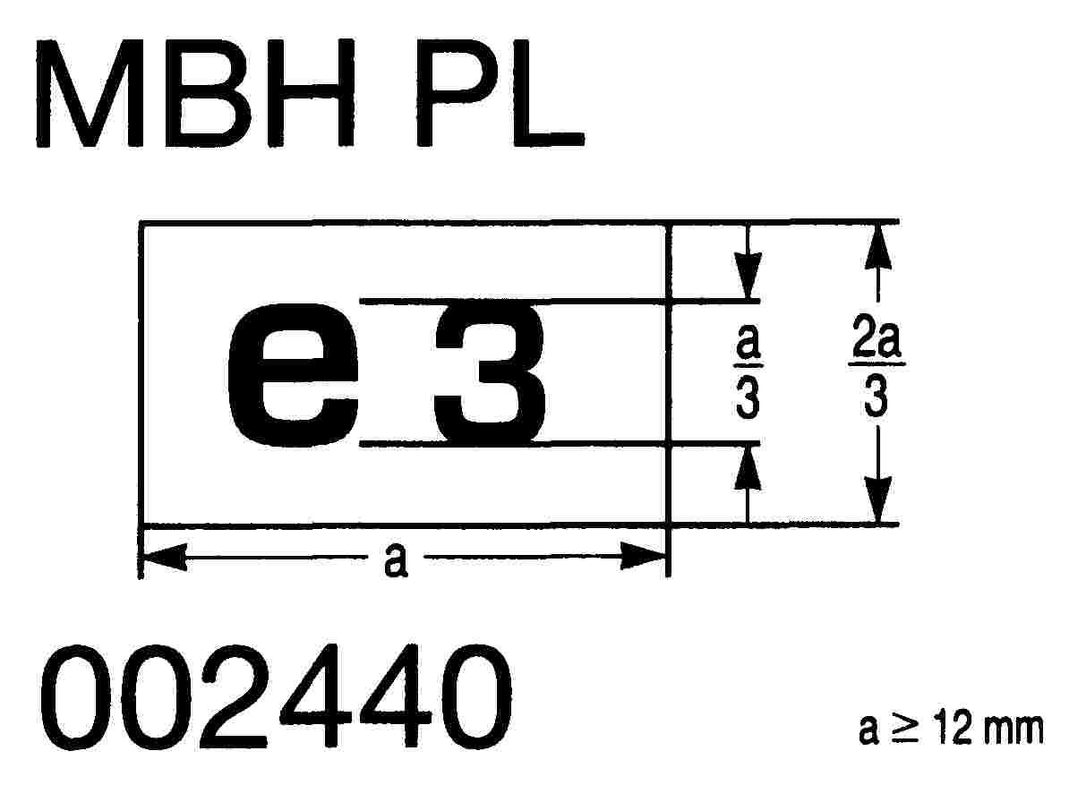
Figure 6
The headlamp bearing the above EC component type-approval mark is a headlamp incorporating a lens of plastic material and meeting the requirements of Annex III-C to this Directive in its original version.
It is so designed that the filament of the passing beam can be lit together simultaneously with the driving beam and/or another reciprocally incorporated lighting function.
|
|
|
|
The headlamp bearing the EC component type-approval mark shown above is a headlamp meeting the requirements of Annex III-D to this Directive in its original version. |
|
|
With respect to the passing beam only, and designed for left-hand traffic only. |
With respect to the driving beam only. |
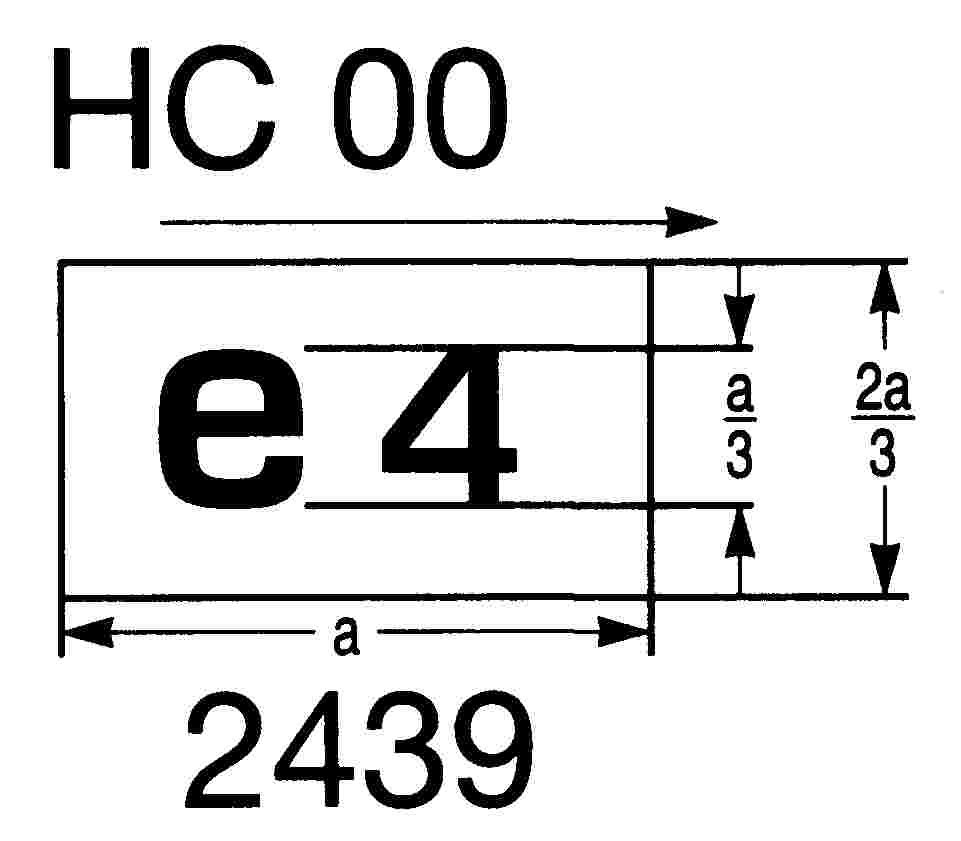

|
|
|
|
The headlamp bearing the EC component type-approval mark shown above is a headlamp incorporating the lens of plastic material meeting the requirements of Annex III-D to this Directive in its original version with respect to the passing beam only, and designed: |
|
|
For both traffic systems |
For right-hand traffic only. |

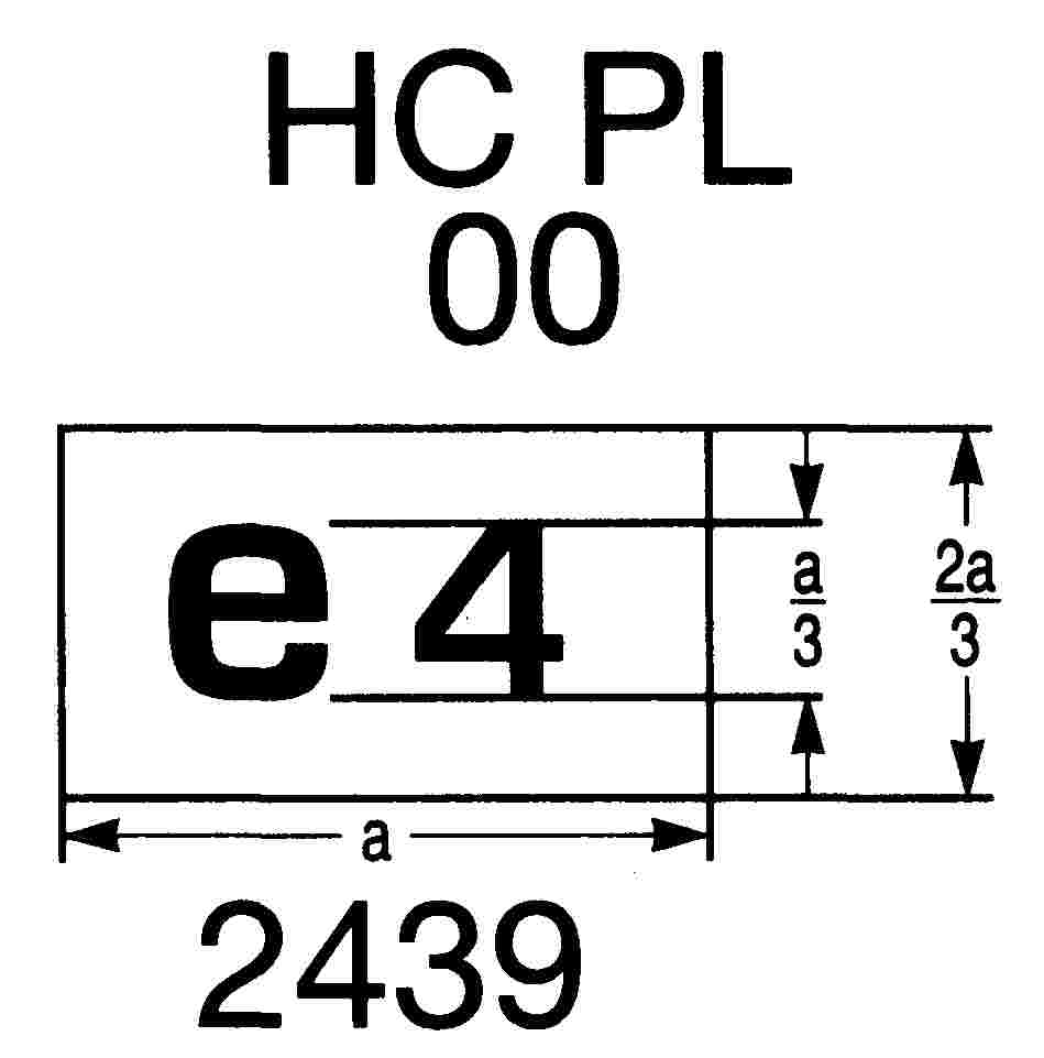
Simplified marking for grouped, combined or reciprocally incorporated lamps
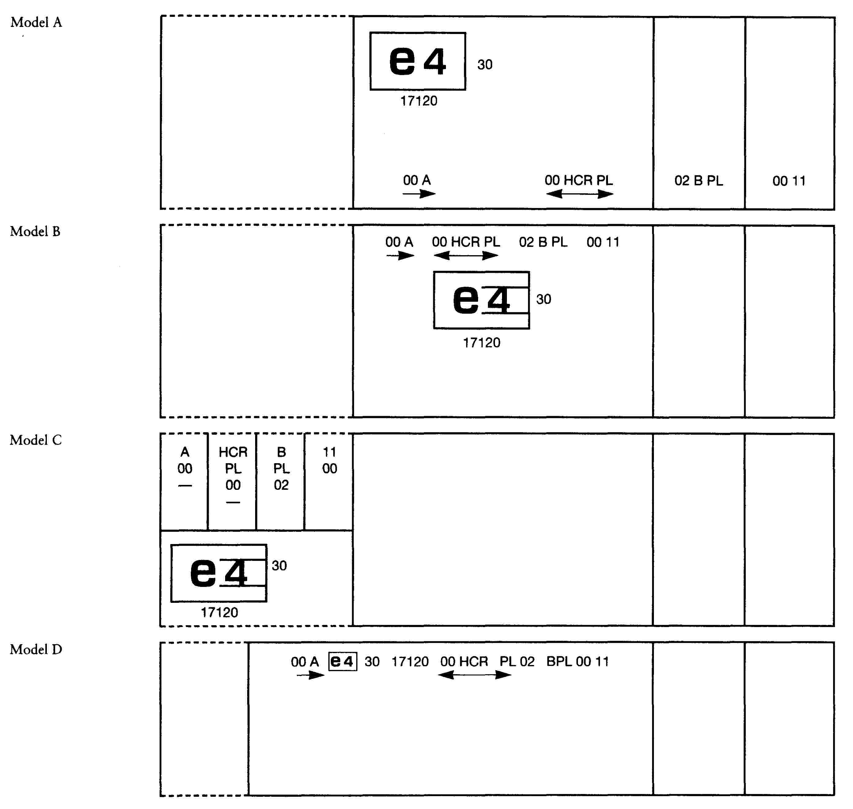
Figure 11
(The vertical and horizontal lines schematize the shape of the light-signalling device. These are not part of the EC component type-approval mark.)
Note:
The four examples shown above correspond to a lighting device bearing an EC component type-approval mark relating to:
— a front position (side) lamp (A) approved in accordance with Annex II to this Directive in its original version;
— a headlamp (HCR) with a passing beam designed for right-hand and left-hand traffic and a driving beam with a maximum intensity comprised between 86.250 and 101.250 candelas (as indicated by the number 30), approved in accordance with Annex III-D to this Directive in its original version and incorporating a lens of plastic material;
— a front fog-lamp B approved in accordance with Directive 76/762/EEC in its original version and incorporating a lens of plastic material;
— a front direction-indicator lamp of category 11 approved in accordance with Annex II to this Directive in its original version.
|
|
|
|
The headlamp bearing the EC component type-approval mark shown above is a headlamp meeting the requirements of Directive 76/761/EEC: |
|
|
With respect to the passing beam only, and designed for left-hand traffic only. |
With respect to the driving beam only. |

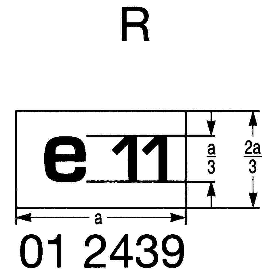
|
|
|
|
Identification of a headlamp incorporating the lens of plastic material meeting the requirements of Directive 76/761/EEC with respect to Appendix 3 of Annex III-D to this Directive. |
|
|
For both the passing beam and the driving beam and designed for right-hand traffic only. |
For the passing beam only and designed for left-hand traffic only. |
|
The passing lamp filament must not be lit simultaneously with the driving lamp filament and/or any other headlamp with which it is reciprocally incorporated. |
|
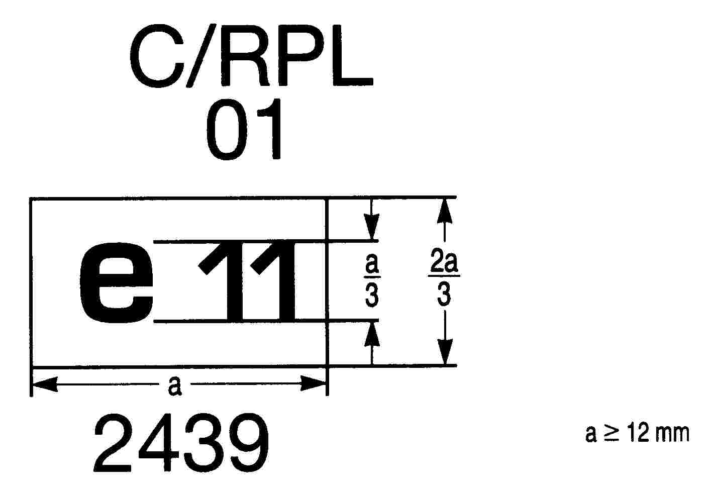

ANNEX II
REQUIREMENTS CONCERNING THE COMPONENT TYPE-APPROVAL OF FRONT POSITION (SIDE) LAMPS, REAR LAMPS, STOP LAMPS, DIRECTION-INDICATOR LAMPS, REAR REGISTRATION-PLATE ILLUMINATING DEVICE, FRONT FOG-LAMPS, REAR FOG-LAMPS, REVERSING LAMPS AND RETRO-REFLECTORS FITTED TO TWO OR THREE-WHEEL MOTOR VEHICLES
1. DEFINITIONS
The relevant definitions set out in Annex I to Council Directive 93/92/EEC of 29 October 1993 on the fitting of lighting and light-signalling devices to two or three-wheel motor vehicles apply.
|
1.1. |
‘Lens’ means the outermost component of the lamp (device) which transmits light through the illuminating surface; |
|
1.2. |
‘Coating’ means any product or products applied in one or more layers to the outer face of a lens; |
|
1.3. |
‘Devices of different types’ are devices which differ in such essential respects as:
|
2. INFORMATION THAT IS ADDITIONAL TO THE COMPONENT TYPE-APPROVAL MARK FOR DIRECTION INDICATORS:
|
2.1. |
In the general case of a direction indicator a number stating that it is a front direction-indicator (category 11) or a rear direction-indicator (category 12) must be affixed close to the rectangle for the component type-approval mark and opposite the component type-approval number. |
|
2.2. |
In the case of a direction indicator which does not, in accordance with 4.7.1. on one side achieve the minimum luminous intensity required up to an angle of H = 80o, a horizontal arrow, the tip of which is pointing in the direction where the minimum luminous intensity in accordance with 4.7.1 is achieved up to an angle of at least H = 80o, must be affixed below the rectangle for the component type-approval mark. |
3. GENERAL REQUIREMENTS
Devices must be designed and constructed in such a way that, under their normal conditions of use and despite any vibrations to which they may be submitted, their proper functioning remains unimpaired and they retain the characteristics required by this Annex.
4. INTENSITY OF THE LIGHT EMITTED
Within the reference axis the intensity of the light emitted by each of the two devices must be at least equal to the two minimum values and at most equal to the maximum values set out in the table below. In no direction must the maximum values stated be exceeded.
|
min (cd) |
max (cd) |
||
|
4.1. |
Rear position (side) lamps |
4 |
12 |
|
4.2. |
Front position (side) lamps |
4 |
60 |
|
4.3. |
Stop lamps |
40 |
100 |
|
4.4. |
Direction-indicator lamps |
||
|
4.4.1. |
Front (category 11) (see Appendix 1) |
90 |
700 (1) |
|
4.4.2. |
Rear (category 12) (see Appendix 1) |
50 |
200 |
|
(1) Applies solely to the area between the two vertical lines passing through V = 0o/H = ± 5o and two horizontal lines passing through V = ± 10o/H = 0o. A maximum of 400 cd is applicable to all other directions. |
|||
|
4.5. |
Outside the reference axis the intensity of the light emitted within the angular fields defined in the diagrams in Appendix 1 must, in each direction corresponding to the points in the light distribution table set out in Appendix 2, be at least equal to the product of the minima set out in 4.1 to 4.4 and to the percentage set out in that table for the direction at issue. |
|
4.6. |
By way of derogation from 4.1 a maximum luminous intensity of 60 cd is permitted for rear position (side) lamps that are reciprocally incorporated with stop lamps below a plane forming an angle of 5o downwards from the horizontal plane. |
|
4.7. |
Moreover:
|
|
4.8. |
The light intensities must be measured with the lamp constantly lit. Where lamps operate intermittently it must be ensured that the device does not overheat. |
|
4.9. |
Appendix 2 as referred to in 4.5 provides details on the methods of measurement to be used. |
|
4.10. |
The rear registration-plate illuminating device must meet the conditions set out in Appendix 3. |
|
4.11. |
The photometric performance of lamps equipped with several light sources must be checked in accordance with the provisions of Appendix 2. |
5. CONDITIONS ATTACHED TO THE TESTS
|
5.1. |
All the measurements must be carried out with a standard colourless lamp falling within the category intended for the device and adjusted in order to emit the reference light flux required for the lamp at issue. However, for lamps equipped with non-replaceable light sources, all measurements must be made at 6,75 V and 13,5 V respectively. |
|
5.2. |
The vertical and horizontal edges of the light-emitting surface of the device are determined and dimensioned in relation to its reference centre. |
6. COLOUR OF LIGHT EMITTED
Stop lamps and rear position (side) lamps must emit red light, front position (side) lamps must emit white light, and direction indicators amber light.
The colour of the light emitted, measured by using a filament lamp of the category specified by the manufacturer, must be within the limits of the trichromatic coordinates prescribed in Appendix 1 to Annex I when this filament lamp is operated at its test voltage as specified in Annex IV.
However, for lamps equipped with non-replaceable light sources, the colorimetric characteristics must be verified with the light sources present in the lamps at a voltage of 6,75 V, 13,5 V or 28,0 V.
7. FRONT AND REAR FOG-LAMPS
The requirements of Directive 76/762/EEC on front fog-lamps and of Directive 77/538/EEC on rear fog-lamps apply.
8. REVERSING LAMPS
The requirements of Directive 77/539/EEC on reversing lamps apply.
9. RETRO-REFLECTORS
9.1. Pedal retro-reflectors
|
9.1.1. |
The shape of the retro-reflectors must be so that these are able to fit into a rectangle, the side dimensions of which are in a ratio of not more than 8. |
|
9.1.2. |
The pedal retro-reflectors must meet the requirements set out in Annex VIII to Directive 76/757/EEC in amber colour. |
|
9.1.3. |
The functioning reflecting surface of each of the four pedal retro-reflectors must not be less than 8 cm2. |
9.2. Other retro-reflectors
The requirements set out in Directive 76/757/EEC on retro-reflectors apply.
Appendix 1
Minimum horizontal (H) and vertical (V) angles of spatial light distribution

Appendix 2
Photometric measurements
1. METHODS OF MEASUREMEMT
|
1.1. |
Interference reflections during the photometric measurements must be avoided by means of appropriate masking. |
|
1.2. |
Should the results of the measurements be contested, they must be carried out in such a way that:
|
2. STANDARDIZED TABLE SHOWING SPATIAL DISTRIBUTION OF LIGHT

|
2.1. |
Direction H = 0o and V = 0o corresponds to the axis of reference (on the vehicle it is horizontal and parallel to the median longitudinal plane of the vehicle and pointing towards the required field of view). It passes through the centre of reference. The values set out in the table give the minimum intensities for the various directions of measurement as a percentage of the minimum required for each lamp within the axis (in direction H = 0o and V = 0o). |
|
2.2. |
Within the field of light distribution represented in diagrammatic form in section 2 by a grid, the distribution of the light must essentially be uniform in such a way that the light intensity in each direction of a part of the field formed by the lines of the grid reaches at least the lowest minimum value specified as a percentage (or the lowest available value) on the lines of the grid which surround the direction at issue. |
3. PHOTOMETRIC MEASUREMENT OF LAMPS EQUIPPED WITH SEVERAL LIGHT SOURCES
The photometric performance must be checked:
|
3.1. |
For non-replaceable (fixed) filament lamps or other light sources: at the voltage prescribed by the manufacturer; the technical service may require from the manufacturer the special power supply needed to supply such lamps. |
|
3.2. |
For replaceable filament lamps: when equipped with mass-production filament lamps at 6,75 V, 13,5 V or 28,0 V the luminous intensity values produced must lie between the maximum limit and the minimum limit given in this Annex increased in accordance with the permissible deviation of the luminous flux permitted for the type of filament lamp chosen, as stated in Annex IV for production filament lamps; alternatively a standard filament lamp may be used in turn, in each of the inidvidual positions, operated at its reference flux, the individual measurements in each position being added. |
Appendix 3
Photometric measurements of the rear registration-plate illuminating device
1. POSITION TO BE ILLUMINATED
Devices may fall within category 1 or 2. The category 1 devices must be designed in such a way as to illuminate a position measuring at least 130 × 240 mm and the category 2 devices in such a way as to illuminate a position measuring at least 200 × 280 mm.
2. COLOUR OF LIGHT EMITTED
The colour of the light emitted by the lamp used in the device must be white, but sufficiently neutral so as not to cause any appreciable change in the colour of the registration plate.
3. LIGHT INDICENCE
The manufacturer of the illuminating device must lay down the conditions for the fitting of the device in relation to the position intended for the registration plate. That device must occupy a position such that at none of the points on the surface to be illuminated with the angle of incidence of the light on the surface of the plate exceed 82o, that angle being measured in relation to the extremity of the light-emitting surface of the device that is furthest from the surface of the plate. Where there is more than one optical component this requirement applies only to the part of the plate intended to be illuminated by the relevant component.
The device must be designed in such a manner that no ray of light shines directly towards the rear with the exception of rays of red light where the device is combined or grouped with a rear lamp.
4. METHOD OF MEASUREMENT
The levels of luminance are measured on a sheet of clean white blotting paper having a minimum factor of diffuse reflection of 70 % and the same dimensions as the registration plate and placed at the position it would normally occupy but 2 mm in front of its support.
The level of luminance is measured at right angles to the surface of the paper at the points shown in the diagram in section 5 below, each point representing a circular area 25 mm in diameter.
5. PHOTOMETRIC CHARACTERISTICS
Luminance B must be at least 2 cd/m2 at each of the measuring points defined below.
|
|
|

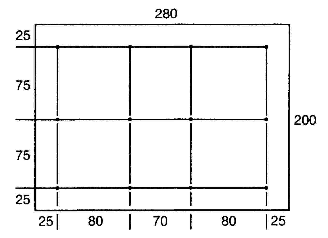
The luminance gradient between values B1 and B2, measured at any two points 1 and 2 selected from among the points referred to above must not exceed 2 × Bo/cm, Bo being the minimum luminance recorded at the various measuring points, or in other words
![]()
Appendix 4
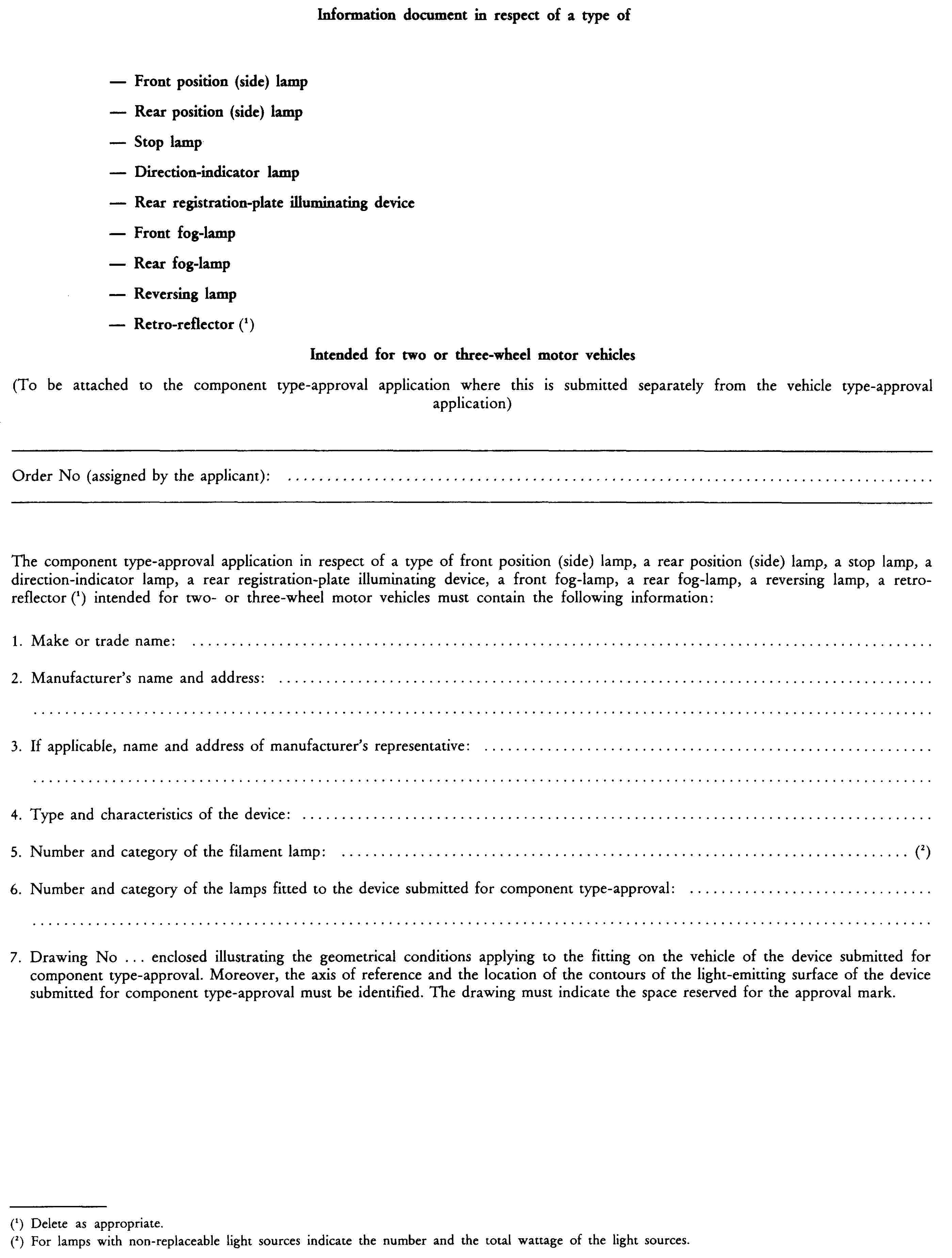
Appendix 5

ANNEX III
REQUIREMENTS RELATING TO THE COMPONENT TYPE-APPROVAL OF DEVICES (HEADLAMPS) USING INCANDESCENT OR HALOGEN FILAMENT LAMPS EMITTING A PASSING AND/OR DRIVING BEAM FITTED TO TWO OR THREE-WHEEL MOTOR VEHICLES
1. DEFINITIONS
The relevant definitions set out in Annex I to Directive 93/92/EEC apply.
|
1.1. |
‘Lens’ means the outermost component of the headlamp (unit) which transmits light through the illuminating surface; |
|
1.2. |
‘Coating’ means any product or products applied in one or more layers to the outer face of a lens; |
|
1.3. |
‘Headlamps of different types’ are headlamps which differ in such essential respects as:
|
2. HEADLAMPS
A distinction is drawn between:
2.1. Headlamps for mopeds
(see Annex III-A)
|
2.1.1 |
with a single-filament lamp |
15 W (category S3) |
|
2.1.2. |
with a two-filament lamp |
15/15 W (category S4) |
|
2.1.3. |
with a single-filament halogen lamp |
15 W (category HS2) |
2.2. Headlamps for motorcycles and tricycles
(see Annexes IIIB and IIIC)
|
2.2.1. |
with a two-filament lamp |
25/25 W (category S1) |
|
2.2.2. |
with a two-filament lamp |
35/35 W (category S2) |
|
2.2.3. |
with a two-filament halogen lamp |
35/35 W (category HS1) |
|
2.2.4. |
with a two-filament lamp |
40/45 W (category R2) |
2.3. Headlamps for motorcycles and tricycles
(see Annex III-D — headlamps with halogen filament lamps other than HS1)
|
2.3.1. |
with a single filament lamp |
55 W (category H1) |
|
2.3.2. |
with a single filament lamp |
55 W (category H2) |
|
2.3.3. |
with a single filament lamp |
55 W (category H3) |
|
2.3.4. |
with a single filament lamp |
60 W (category HB3) |
|
2.3.5. |
with a single filament lamp |
51 W (category HB4) |
|
2.3.6. |
with a single filament lamp |
55 W (category H7) |
|
2.3.7. |
with a two-filament lamp |
55/60 W (category H4) |
ANNEX III-A
HEADLAMPS FOR MOPEDS
1. GENERAL REQUIREMENTS
|
1.1. |
Headlamps must be designed and manufactured in such a way that, under normal conditions of use and despite any vibrations to which they may be exposed, they continue to function correctly and retain the characteristics laid down in this Annex. |
|
1.2. |
The parts intended to attach the lamp must be designed in such a way that, even in the dark, the lamp may be correctly fitted in its appropriate position. |
2. SPECIFIC REQUIREMENTS
|
2.1. |
The correct position of the lens in relation to the optical system must be clearly marked and locked in position in order to prevent rotation during use. |
|
2.2. |
A measuring screen as described in Appendix 1 or 2 and a standard lamp using a smooth colourless filament lamp falling within one of the categories provided for in section 2.1 and in Annex III must be used in order to check the illumination provided by the headlamp. The standard lamps must be adjusted to the relevant reference light flux in accordance with the values laid down for those lamps in the relevant technical document (see Annex IV). |
|
2.3. |
The passing beam must produce a cut-off of such sharpness that correct adjustment by means thereof is a practical possibility. The cut-off must be perceptibly horizontal and as straight as possible over a horizontal length of at least ± 900 mm, measured at a distance of 10 m (in the case of a halogen lamp): length of at least ± 2 250 mm measured at a distance of 25 m; see Appendix 2). When adjusted in accordance with Appendix 1 headlamps must meet the conditions set out therein. |
|
2.4. |
The light distribution must not vary in lateral terms in a way that impairs good visibility. |
|
2.5. |
The illumination on the screen referred to in 2.2 must be measured by means of a photo receiver for a usable area lying within a 65 mm square. |
3. ADDITIONAL REQUIREMENTS ATTACHED TO ANY INSPECTIONS WHICH MAY BE CARRIED OUT BY THE COMPETENT AUTHORITIES WHEN CHECKING CONFORMITY OF PRODUCTION IN ACCORDANCE WITH SECTION 5.2.4 OF ANNEX I
Any records of the photometric characteristics of headlamps taken in accordance with the general requirements concerning conformity testing must be restricted to points HV — LH — RH — L600 — R600 (see figure in Appendix 1).
Appendix 1
Photometric tests on headlamps equipped with category S3 and S4 lamps
|
1. |
For the measurements the measuring screen is placed at a distance of 10 m in front of the headlamp and at right angles to the line joining the driving beam filament of the lamp and point HV (see figure below); line H-H must be horizontal. |
|
2. |
REQUIREMENTS ATTACHED TO PASSING BEAM
|
|
3. |
REQUIREMENTS CONCERNING THE DRIVING BEAM (if any)
|
|
(dimensions in mm over a distance of 10 m) Figure |
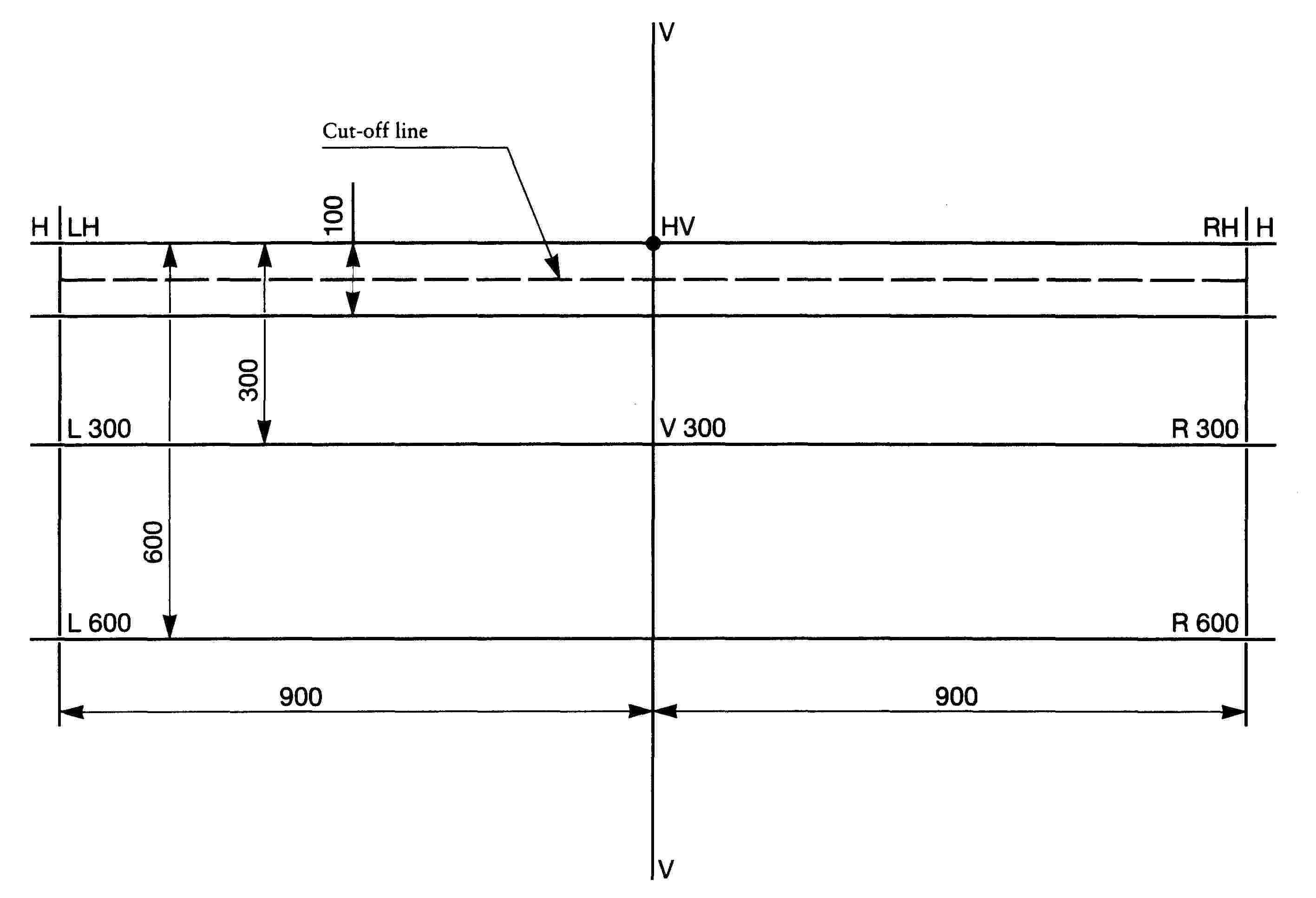
Appendix 2
Photometric tests on headlamps equipped with category HS2 halogen lamps
|
1. |
For the measurements the measuring screen is placed 25 m in front of the headlamp in such a way that it is at right angles to the line joining the filament of the lamp and pont HV (see figure below); line H-H must be horizontal. |
|
2. |
In lateral terms the headlamp must be aligned in such a way that the distribution of the beam is symmetrical in relation to line V-V. |
|
3. |
In vertical terms the headlamp must be adjusted in such a way that its cut-off is 250 mm below line H-H. It must also be as horizontal as possible. |
|
4. |
When the headlamp has been adjusted in accordance with sections 2 and 3 the following conditions must be met:
|
|
5. |
Measuring screen MEASURING SCREEN
(dimensions in mm over a distance of 25 m) Figure |

Appendix 3
Appendix 4

ANNEX III-B
HEADLAMPS FOR MOTORCYCLES AND TRICYCLES EMITTING A SYMMETRICAL PASSING BEAM AND A DRIVING BEAM BY MEANS OF FILAMENT LAMPS
1. ADDITIONAL REQUIREMENTS CONCERNING MARKS AND THE MARKING OF SPECIFIC DEVICES
|
1.1. |
Headlamps must bear in a clearly legible and indelible manner the letters ‘MB’ (symbol for driving-beam headlamp) opposite the component type-approval number. |
|
1.2. |
All headlamps designed in such a way as to preclude any simultaneous lighting-up of the passing-beam filament and that of any other light source with which they may be integrated may be marked with an oblique stroke (/) following the symbol (MB) for the passing beam in the component type-approval mark. |
|
1.3. |
On headlamps incorporating a lens of plastic material, the letters ‘PL’ must be affixed near the symbol prescribed in 1.1. |
2. GENERAL REQUIREMENTS
|
2.1. |
Each of the samples must meet the specifications set out in section 3 below. |
|
2.2. |
Headlamps must be designed and manufactured in such a way that, under normal conditions of use and despite any vibrations to which they may be exposed, they continue to function properly and retain the required characteristics.
|
|
2.3. |
The parts intended to attach the filament lamp must be made in such a way that, even in the dark, the filament lamp can be attached without uncertainty in its appropriate position. |
|
2.4. |
Additional tests meeting the requirements of Appendix 2 must be carried out in order to ensure that there are no excessive variations in photometric performance during use. |
|
2.5. |
If the lens of the headlamp is of plastic material, additional tests must be carried out in accordance with the requirements of Appendix 3. |
3. SPECIFIC REQUIREMENTS
|
3.1. |
The correct position of the lens in relation to the optical system must be clearly marked and locked in position in order to prevent rotation during use. |
|
3.2. |
In order to check the illumination produced by the headlamp a measuring screen as described in Appendix 1 is used, together with a standard lamp (S1 and/or S2, see Annex IV) having a smooth colourless filament lamp. Standard lamps must be adjusted to the relevant reference light flux applying in accordance with the values required for such lamps. |
|
3.3. |
The passing beam must produce a cut-off of such sharpness that correct adjustment by means thereof is a practical possibility. The cut-off must be as straight and as horizontal as possible over a horizontal length of at least ± 5o. When adjusted in accordance with Appendix 1 headlamps must meet the conditions set out therein. |
|
3.4. |
The light distribution must not vary in lateral terms in a way that impairs good visibility. |
|
3.5. |
The illumination on the screen referred to in 3.2 must be measured by means of a functioning-surface photocell lying within a 65 mm square. |
4. ADDITIONAL REQUIREMENTS APPLYING TO ANY INSPECTIONS WHICH MAY BE CARRIED OUT BY THE COMPETENT AUTHORITIES WHEN CHECKING CONFORMITY OF PRODUCTION IN ACCORDANCE WITH SECTION 5.1 OF ANNEX I
|
4.1. |
For value in zone III, the maximum unfavourable deviation may be respectively: — 0,3 lux equivalent 20 % — 0,45 lux equivalent 30 %. |
|
4.2. |
if, for the driving beam, HV being situated within the isolux 0,75 Emax, a tolerance of + 20 % for maximum values and - 20 % for minimum values is observed for the photometric values at any measuring point specified in sections 4.3 and 4.4 of Appendix 1 to this Directive. |
|
4.3. |
With respect to the verification of the change in the vertical position of the cut-off line under the influence of heat, the following procedure is applied: One of the sampled headlamps is tested in accordance with the procedure described in section 2.1 of Appendix 2 after being subjected three consecutive times to the cycle described in section 2.2.2 of Appendix 2. The headlamp is considered to be acceptable if Δr does not exceed 1,5 mrad. If this value exceeds 1,5 mrad but is not more than 2,0 mrad, a second headlamp is subjected to the test, after which the mean of the absolute values recorded on both samples may not exceed 1,5 mrad. |
Appendix 1
Photometric tests
|
1. |
For adjustment purposes the relevant screen must be placed at least 10 m before the headlamp, line h-h being horizontal. For the measurements the photocell must be 25 m in front of the headlamp and at right angles to the line joining the incandescent filament lamp and point HV. |
|
2. |
In lateral terms the headlamp must be aligned in such a way that the distribution of the driving beam is symmetrical in relation to line v-v. |
|
3. |
In vertical terms the headlamp must be adjusted in such way that the passing beam cut-off is 250 mm below line h-h (at a distance of 25 m). |
|
4. |
When the headlamp has been adjusted in accordance with sections 2 and 3, conditions for which are similar to those relating to driving beams, the following conditions must be met:
|
|
5. |
MEASURING AND ADJUSTING SCREEN
(dimensions in mm for a distance of 25 m) |

Appendix 2
Test on the stability of the photometric behaviour of headlamps in operation
Compliance with the requirements of this Appendix is not an adequate criterion for the component type-approval of headlamps incorporating plastic lenses.
See Appendix 2 to Annex III-D.
Appendix 3
Requirements for lamps incorporating lenses of plastic material and testing of lens or material samples and of complete lamps
See Appendix 3 to Annex III-D.
Appendix 4
Appendix 5
ANNEX III-C
HEADLAMPS FOR MOTORCYCLES AND TRICYCLES EMITTING AN ASYMMETRICAL PASSING BEAM AND A DRIVING BEAM AND FITTED WITH HALOGEN FILAMENT LAMPS (HS1 LAMPS) OR FILAMENT LAMPS OF CATEGORY R2
1. ADDITIONAL REQUIREMENTS CONCERNING MARKS AND THE MARKING OF DEVICES
|
1.1. |
Headlamps designed in such a way as to meet the requirement of a single rule of the road (driving on either the right or the left) must, on the lens, bear the limits of the area which may possibly be masked in order to avoid distracting road users in a country where the rule of the road is not that for which the headlamp has been designed. However, when that area is directly identifiable by design any such delimitation is not necessary. |
|
1.2. |
Headlamps designed in such a way as to meet the requirements of driving on the right and those for driving on the left must bear markings in order to locate the two positions for the fixing in position of the light unit on the vehicle or the lamp on the reflector; these markings consist of the letters ‘R/D’ for the position corresponding to driving on the right and the letters ‘L/G’ for the position corresponding to driving on the left. |
|
1.3. |
All headlamps designed in such a way as to preclude any simultaneous lighting-up of the dipped-beam filament and that of any other light source with which they may be associated must be marked with an oblique stroke (/) within the component type-approval mark, after the passing beam headlamp symbol. |
|
1.4. |
Where headlamps meet only the requirements of driving on the left, a horizontal arrow pointing to the right of an observer looking at the headlamp head on, i.e. towards the side of the road driven upon, must be entered below the component type-approval mark. |
|
1.5. |
Where, by means of a deliberate alteration in the adjustment of the light unit or lamp, headlamps meet the requirements of both rules of the road, a horizontal arrow having two tips pointing one to the left and the other to the right must be entered below the component type-approval mark. |
|
1.6. |
The letters ‘MBH’ on headlamps with HS1 lamps are placed opposite the component type-approval mark. |
|
1.7. |
The marks and symbols referred to above must be clearly visible and indelible. |
|
1.8. |
On headlamps incorporating a lens of plastic material, the letters ‘PL’ must be affixed near the symbols prescribed in 1.2 to 1.7. |
2. GENERAL REQUIREMENTS
|
2.1. |
Each of the samples must meet the specifications set out in sections 3 to 5. |
|
2.2. |
Headlamps must be designed and manufactured in such a way that under the normal conditions of use and despite any vibrations to which they may be exposed they continue to function properly and retain the characteristics required by this Annex.
|
|
2.3. |
The parts intended to attach the filament lamp to the reflector must be made in such a way that, even in the dark, the filament lamp can be attached without uncertainty in its appropriate position. |
|
2.4. |
The correct position of the lens in relation to the optical system must be clearly marked and locked in position in order to avoid any rotation. |
|
2.5. |
Where headlamps have been designed in such a way as to meet the requirements of driving on both the right and the left, adaptation to a given rule of the road may be obtained by a suitable initial setting when the vehicle is equipped or via a deliberate action on the part of the user. That initial setting or that deliberate action must, for example, consist of a specific angular setting either of the sealed-beam assembly on the vehicle or of the lamp in relation to that assembly. In all cases only two different setting positions that have been clearly specified and correspond in each case to a rule of the road (driving on the right or left) must be possible and any shift into an intermediate position must be made impossible. When the lamp is able to occupy two different positions the parts intended to attach the lamp to the reflector must be designed and manufactured in such a way that, in each of those two positions, the lamp is attached with the same precision as required for headlamps designed for just one rule of the road. Conformity must be checked visually and, where appropriate, by means of a test assembly. |
|
2.6. |
In order to ensure that operation does not involve any excessive variation in photometric performance, additional tests must be carried out as required by Appendix 2. |
|
2.7. |
If the lens of the headlamps is of plastic material, additional tests must be carried out in accordance with the requirements of Appendix 3. |
3. ILLUMINATION REQUIREMENTS
3.1. General requirements
|
3.1.1. |
Headlamps must be designed in such a way that, with adequate HS1 or R2 lamps, they emit a light that is not dazzling but is nevertheless adequate on passing beam and provides good illumination on driving beam. |
|
3.1.2. |
A screen placed vertically at a distance of 25 m in front of the headlamp, as shown in Appendix 1, must be used to check the illumination produced by the headlamp. |
|
3.1.3. |
A colourless reference lamp designed for a nominal voltage of 12 V must be used in examining headlamps. The current at the terminals of the lamp during examination of the headlamp must be set to the following characteristics:
The headlamp must be considered acceptable if it meets the requirements set out in section 3 with at least one reference lamp which may be presented together with the headlamp. |
|
3.1.4. |
The dimensions determining the position of the filaments within the HS1 or R2 filament reference lamp are set out in Annex IV. |
|
3.1.5. |
The bulb for the filament reference lamp must be of such a shape and optical quality that it causes a minimum of reflection or refraction which may have an adverse effect on the light distribution. |
3.2. Requirement relating to the passing beam
|
3.2.1. |
The passing beam must produce a cut-off of such distinctness that it is possible to carry out adjustments correctly using the said cut-off. The cut-off must be a straight horizontal line on the side opposite to the rule of the road for which the headlamp is intended. On the other side the cut-off must not go beyond either broken line HV-H1 and H4 formed by a straight line formed by HV-H1 lying at an angle of 45o with the horizontal and a straight line H1-H4 offset by 1 % in relation to straight line h-h, or straight line HV-H3 inclined by 15o to the horizontal (see Appendix 1). In no case is a cut-off going beyond both line HV-H2 and line H2-H4 and resulting from the combination of the two preceding possibilities acceptable. |
|
3.2.2. |
The headlamp must be aligned in such a way that:
|
|
3.2.3. |
When aligned in this manner the headlamp must meet the requirements referred to in 3.2.5 to 3.2.7 and 3.3. |
|
3.2.4. |
Where a headlamp aligned as referred to above does not meet the requirements of 3.2.5 to 3.2.7 and 3.3 it is permissible to alter the setting provided that the axis of the beam is not moved sideways by more than 1o (= 44 cm) to the right or left. The incorrect setting limit of 1o to the right or left is not compatible with a vertical incorrect setting upwards or downwards which is restricted only by the requirements laid down in 3.3. However, the horizontal part of the cut-off must not go beyond line h-h. In order to make settings easier by means of the cut-off it is permissible partly to mask the headlamp in order to make the cut-off more distinct. |
|
3.2.5. |
The illumination produced on the screen by the passing beam must meet the requirements set out in the following table:
|
|||||||||||||||||||||||||||||||||||||||||||||||||
|
3.2.6. |
In none of the zones I, II, III and IV must there be lateral variations that impair good visibility. |
|
3.2.7. |
Headlamps designed to meet the requirements of driving on the right and those for driving on the left must, for each of the two locations of the sealed beam unit or lamp meet the requirements set out above for the rule of the road corresponding to the location under consideration. |
3.3. Requirements concerning the driving beam
|
3.3.1. |
The illumination produced on the screen by the driving beam must be measured using the same headlamp setting as for the measurements defined in 3.2.5 to 3.2.7. |
|
3.3.2. |
The illumination produced on the screen by the driving beam must meet the following requirements:
|
|
3.4. |
The illumination on the screen referred to in 3.2.5 to 3.2.7 and 3.3 must be measured by means of a useable-area photo receiver acting within a 65 mm square. |
4. REFRENCE HEADLAMP
A headlamp which:
|
4.1. |
meets the component type-approval requirements set out below; |
|
4.2. |
has an effective diameter of at least 160 mm; |
|
4.3. |
provides illumination, with a reference lamp, at various points within the various areas provided for in 3.2.5;
|
5. ADDITIONAL REQUIREMENTS ATTACHED TO ANY INSPECTIONS WHICH MAY BE CARRIED OUT, BY THE COMPETENT AUTHORITIES WHEN CHECKING CONFORMITY OF PRODUCTION ACCORDING TO SECTION 5.1 OF ANNEX I
|
5.1. |
For values B 50 L (or R) and Zone III the maximum deviation may be respectively
|
|
5.2. |
For the passing beam, the prescribed values in this Directive are met at HV (with a tolerance of 0,2 lux) and related to that aiming at least one point of each area delimited on the measuring screen (at 25 m) by a circle 15 cm in radius around points B 50 L (or R) (with a tolerance of 0,1 lux), 75 R (or L), 50 R (or L), 25 R, 25 L and in the entire area of zone IV which is not more than 22,5 cm above line 25 R and 25 L.
|
|
5.3. |
If the results of the tests described above do not meet the requirements, the alignment of the headlamp may be changed, provided that the axis of the beam is not displaced laterally by more than 1o to the right or left. |
|
5.4. |
Headlamps with apparent defects are disregarded. |
|
5.5. |
The reference mark is disregarded. |
Appendix 1
Measuring screen
UNIFORM EUROPEAN BEAM
Headlamp for driving on the right ( 33 )

(dimensions in mm)
Appendix 2
Tests on the stability of the photometric performance of headlamps in operation
Compliance with the requirements is not a sufficient criterion for the component type-approval of headlamps fitted with plastic lenses.
See Appendix 2 to Annex III-D.
Appendix 3
Requirements for lamps incorporating lenses of plastic material and testing of lens or material samples and of complete lamps
See Appendix 3 to Annex III-D.
Appendix 4

Appendix 5
ANNEX III-D
HEADLAMPS FOR MOTORCYCLES AND TRICYCLES EMITTING AN ASYMMETRICAL PASSING BEAM, A DRIVING BEAM AND FITTED WITH HALOGEN FILAMENT LAMPS OTHER THAN HS1 LAMPS
1. ADDITIONAL REQUIREMENTS CONCERNING MARKS AND THE MARKING OF DEVICES
|
1.1. |
Headlamps designed in such a way as to meet the requirement of a single rule of the road (driving on either the right or the left) must, on the lens, bear the limits of the area which may possibly be masked in order to avoid distracting road users in a country where the rule of the road is not that for which the headlamp has been designed. However, when that area is directly identifiable by design any such delimitation is not necessary. |
|
1.2. |
Headlamps designed in such a way as to meet the requirements of driving on the right and those for driving on the left must bear markings in order to locate the two positions for the fixing in position of the light unit on the vehicle or the lamp on the reflector; these markings consist of the letters ‘R/D’ for the position corresponding to driving on the right and the letters ‘L/G’ for the position corresponding to driving on the left. |
|
1.3. |
All headlamps designed in such a way as to preclude any simultaneous lighting-up of the dipped-beam filament and that of any other light source with which they may be associated must be marked with an oblique stroke (/) within the component type-approval mark, after the passing beam-headlamp symbol. |
|
1.4. |
Where headlamps meet only the requirements of driving on the left, a horizontal arrow pointing to the right of an observer looking at the headlamp head-on, i.e. towards the side of the road driven upon, must be entered below the component type-approval mark. |
|
1.5. |
Where by means of a deliberate alteration in the adjustment of the light unit or lamp, headlamps meet the requirements of both rules of the road, a horizontal arrow having two tips pointing one to the left and the other to the right must be entered below the component type approval mark. |
|
1.6. |
The following additional symbol or symbols:
|
2. GENERAL SPECIFICATIONS
|
2.1. |
Each sample must conform to the specifications set out in sections 6 to 8. |
|
2.2. |
Headlamps must be so made as to retain their prescribed photometric characteristics and to remain in good working order when in normal use, in spite of the vibrations to which they may be subjected.
|
|
2.3. |
The components by which the filaments lamp(s) is/are fixed to the reflector must be made in such a way that, even in darkness, the filament lamp(s) can be fixed in no other position but the correct one ( 34 ) ( 35 ). The filament lamp-holder must conform to the dimensional characteristics as given in the following data sheets of CIE Publication 61-2:
|
|
2.4. |
Headlamps designed to satisfy the requirements of both right-hand and left-hand traffic may be adapted for traffic on a given side of the road either by an appropriate initial setting when fitted on the vehicle or by selective setting by the user. Such initial or selective setting may consist, for example, of fixing either the optical unit at a given angle on the vehicle or the filament lamp at a given angle in relation to the optical unit. In all cases, only two precise setting positions, one for right-hand and one for left-hand traffic, must be possible, and the design must preclude inadvertent shifting of the headlamp from one position to the other or its setting in an intermediate position. Where two different setting positions are provided for the filament lamp, the components attaching the filament lamp to the reflector must be designed and made so that, in each of its two settings, the filament lamp is held in position with the precision required for headlamps intended for traffic on only one side of the road. Conformity with the requirements of this section must be verified visually and, where necessary, by a test fitting. |
|
2.5. |
Only for headlamps equipped with single-filament halogen lamps: On headlamps designed to provide alternately a driving beam and a passing beam, any mechanical, eletro-mechanical or other device incorporated in the headlamp for switching from one beam to the other ( 36 ) must be so constructed that:
|
|
2.6. |
Complementary tests must be carried out in accordance with the requirements of Appendix 2 to ensure that in use there is no excessive change in photometric performance. |
|
2.7. |
If the lens of the headlamp is of plastic material, tests must be carried out in accordance with the requirements of Appendix 3. |
3. ILLUMINATION
3.1. General provisions
|
3.1.1. |
Headlamps must be made in such a way that, with suitable H1, H2, H3, HB3, HB4, H7 and/or H4 filament lamps, they provide adequate illumination without dazzle in the case of the passing beam and good illumination in the case of the driving beam. |
|
3.1.2. |
The illumination produced by the headlamp must be checked on a vertical screen set at a distance of 25 m in front of the headlamp and at right angles to its axis (see Appendix 1). |
|
3.1.3. |
The headlamps must be checked by means of (a) standard (reference) filament lamp(s) designed for a rated voltage of 12 V. During the checking of the headlamp, the voltage at the terminals of the filament lamp must be regulated so as to obtain the following characteristics:
The headlamp is deemed satisfactory if the photometric requirements are met with at least one standard (reference) 12-volt filament lamp which may be supplied with the headlamp. |
|
3.1.4. |
The dimensions determining the position of the filament inside the standard (reference) 12-volt filament lamp are shown on the relevant data sheet of Annex 4. |
|
3.1.5. |
The bulb of the standard (reference) filament lamp must be of such optical shape and quality that it does not cause any reflection or refraction adversely affecting the light distribution. Compliance with this requirement must be checked by measuring the light distribution obtained when a standard headlamp is fitted with the standard (reference) filament lamp. |
3.2. Provisions regarding passing beams
|
3.2.1. |
The passing beam must produce a sufficiently sharp cut-off to permit satisfactory adjustment with its aid. The cut-off must be horizontal straight line on the side opposite to the direction of traffic for which the headlamps is intended; on the other side it must extend neither beyond the broken line H-V, H1-H4 formed by a straight line HV-H1 standing at an angle of 45o to the horizontal and a straight line H1-H4 lying 25 cm above the straight line hh, nor beyond the straight line HV-H3, inclined at an angle of 15o above the horizontal (see Appendix 1). A cut-off extending beyond both line HV-H2 and H2-H4 and resulting from a combination of the above two possibilities shall in no circumstances be permitted. |
|
3.2.2. |
The headlamp must aimed in such a way that:
|
|
3.2.3. |
when so aimed the headlamp need, if its approval is sought solely for a passing beam ( 39 ), comply only with the requirements referred to in 3.2.5 to 3.2.7 and 3.3. |
|
3.2.4. |
Where a headlamp so aimed does not meet the requirements of 3.2.5 to 3.2.7 and 3.3, its alignment may be changed provided that the axis of the beam is not laterally displaced by more than 1o (= 44 cm) to the right or left ( 40 ). To faciltate adjustment by means of the cut-off, the headlamp may be partially occluded in order to sharpen the cut-off. |
|
3.2.5. |
The illumination produced on the screen by the passing beam must meet the following requirements:
|
|||||||||||||||||||||||||||||||||||||||||||||||||||||||||||||||||||||
|
3.2.6. |
There must be no lateral variations detrimental to good visibility in any of the zones I, II, III and IV. |
|
3.2.7. |
The illumintation values in zones ‘A’ and ‘B’ as shown in figure C in Annex IV must be checked by the measurement of the photometric values of points 1 to 8 on this figure; these values must lie within the following limits: — 0,7 lux ≥ 1, 2, 3, 7 ≥ 0,1 lux — 0,7 lux ≥ 4, 5, 6, 8 ≥ 0,2 lux |
|
3.2.8. |
Headlamps designed to meet the requirements of both right-hand and left-hand traffic must in each of the two setting positions of the optical unit or of the filament lamp, meet the requirements set out above for the corresponding direction of traffic. |
3.3. Provisions regarding driving beams
|
3.3.1. |
In the case of a headlamp designed to provide a driving beam and a passing beam, measurements of the illumination produced on the screen by the driving beam must be taken with the same headlamp alignment as for measurements under 3.2.5 to 3.2.7. In the case of a headlamp providing a driving beam only, it must be adjusted that the area of maximum illumination is centred on the point of intersection of the lines h-h and v-v. Such a headlamp need meet only the requirements referred to in 3.3. |
|
3.3.2. |
The illumination produced on the screen by the driving beam must meet the following requirements:
|
|
3.4. |
The screen illumination values referred to in 3.2.5 to 3.2.7 and 3.3 must be measured by means of a photoreceptor, the effective area of which must be contained within a square of 65 mm side. |
4. GAUGING DISCOMFORT
The discomfort caused by the passing beam of headlamps must be gauged.
5. STANDARD HEADLAMP
|
5.1. |
A headlamp is deemed to be a standard (reference) headlamp if it:
|
6. ADDITIONAL REQUIREMENTS ATTACHED TO ANY INSPECTIONS WHICH MAY BE CARRIED OUT BY THE COMPETENT AUTHORITIES WHEN CHECKING CONFORMITY OF PRODUCTION IN ACCORDANCE WITH SECTION 5.1 OF ANNEX I
|
6.1. |
For values B 50 L (or R) and Zone III the maximum deviation may be respectively
|
|
6.2. |
For the passing beam, the prescribed values in this Directive are met at HV (with a tolerance of 0,2 lux) and related to that aiming at least one point of each area delimited on the measuring screen (at 25 m) by a circle 15 cm in radius around point B 50 L (or R) (with a tolerance of 0,1 lux), 75 R (or L), 50 R (or L), 25 R, 25 L and in the entire area of zone IV which is not more than 22,5 cm above line 25 R and 25 L.
|
|
6.3. |
If the results of the tests described above do not meet the requirements, the alignment of the headlamp may be changed, provided that the axis of the beam is not displaced laterally by more than 1o to the right or left. |
|
6.4. |
Headlamps with apparent defects are disregarded. |
|
6.5. |
The reference mark is disregarded. |
Appendix 1
Measuring screen
Standard European beam
A. Headlamp for right-hand traffic
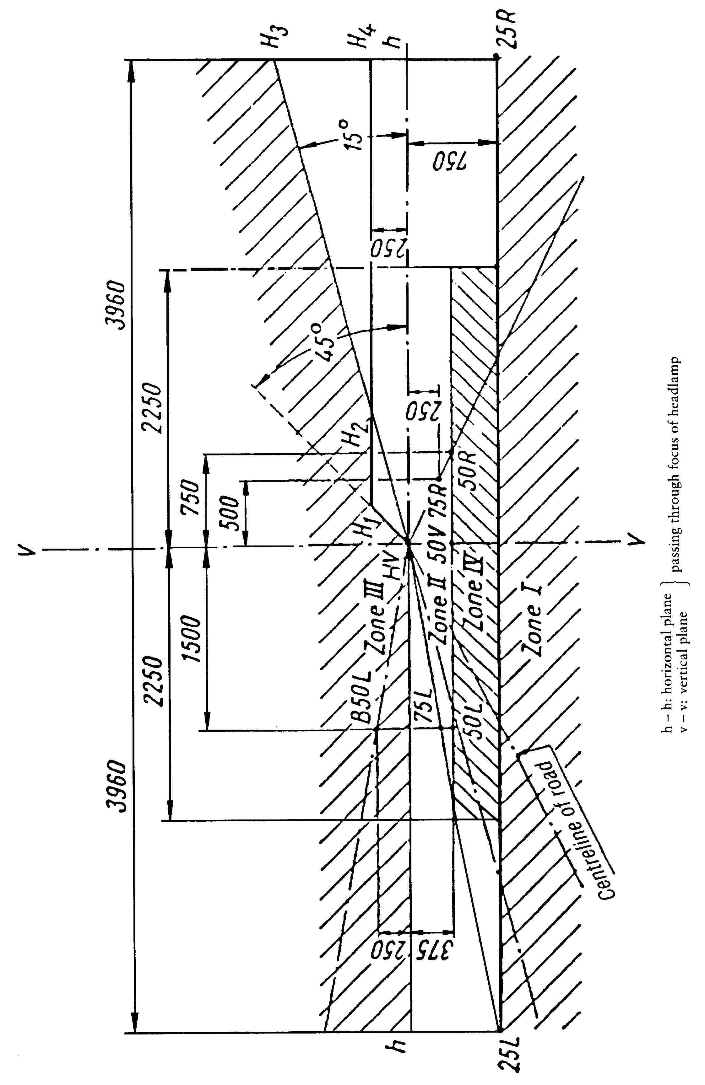
(dimensions in mm)
B. Headlamp for left-hand traffic

(dimensions in mm)
C. Measuring points for illumination values

Note:
Figure C shows the measuring point for right-hand traffic. Points 7 and 8 move to their corresponding location at the right-hand side of the picture for left-hand traffic.
Appendix 2
Tests on the stability of the photometric performance of headlamps in operation
TESTS ON COMPLETE HEADLAMPS
Once the photometric values have been measured according to the requirements of this Directive, in points Emax for driving beam and HV, 50 R, B 50 L for passing beam (or HV, 50 L, B 50 R for headlamps designed for left-hand traffic) a complete headlamp sample is tested for stability of photometric performance in operation. ‘Complete headlamp’ is understood to mean the complete lamp itself including those surrounding body parts and lamps which could influence its thermal dissipation.
1. TEST OF STABILITY OF PHOTOMETRIC PERFORMANCE
The tests are carried out in a dry and still atmosphere at an ambient temperature of 23 oC ± 5 oC, the complete headlamp being mounted on a base representing the correct installation on the vehicle.
1.1. Clean headlamp
The headlamp is operated for 12 hours as described in 1.1.1 and checked as prescribed in 1.1.2.
1.1.1. Test procedure
The headlamp is operated for a period according to the specified time, so that:
|
1.1.1.1. |
(a) in the case where only one lighting function (driving or passing beam) is to be approved, the corresponding filament is for the prescribed time ( 41 ), (b) in the case of a reciprocally incorporated passing lamp and driving lamp (dual-filament lamp or two filament lamps): (c) in the case of grouped lighting functions all the individual functions must be lit simultaneously for the time specified for individual lighting functions (a) also taking into account the use of reciprocally incorporated lighting functions (b), according to the manufacturer's specifications. |
|
1.1.1.2. |
Test voltage The voltage must be adjusted so as to supply 90 % of the maximum wattage specified in Annex IV. The applied wattage must in all cases comply with the corresponding value of a filament lamp of 12 V rated voltage, except if the applicant for approval specifies that the headlamp may be used at a different voltage. In the latter case, the test is carried out with the filament lamp whose wattage is the highest that can be used. |
1.1.2. Test results
|
1.1.2.1. |
Visual inspection Once the headlamp has been stabilized to the ambient temperature, the headlamp lens and the external lens, if any, must be cleaned with a clean, damp cloth. It must then be inspected visually; no distortion, deformation, cracking or change in colour of either the headlamps or the external lens, if any, must be noticeable. |
|
1.1.2.2. |
Photometric test To comply with the requirements of this directive, the photometric values must be verified in the following points: Passing beam: — 50 R — B 50 L — HV for headlamps designed for right-hand traffic, — 50 L — B 50 R — HV for headlamps designed for left-hand traffic. Driving beam: — Point of Emax. — Another adjustment may be carried out to allow for any deformation of the headlamp base due to heat (the change of the position of the cut-off line is covered in section 2 of this Appendix). — A 10 % discrepancy between the photometric characteristics and the values measured prior to the test is permissible, including the tolerances of the photometric procedure. |
1.2. Dirty headlamp,
After being tested as specified in 1.1, the headlamp must be operated for one hour as described in 1.1.1, after being prepared as prescribed in 1.2.1, and checked as prescribed in 1.1.2.
1.2.1. Preparation of the headlamp
|
1.2.1.1. |
Test mixture The mixture of water and polluting agent to be applied to the headlamp must be composed of nine parts (by mass) of silica sand with a grain size distributed between 0 and 100 μm, one part (by mass) of vegetal carbon dust of a grain size distributed between 0 and 100 μm, 0,2 (by mass) of NaCMC ( 45 ) and an appropriate quantity of distilled water, the conductivity of which is lower than 1 mS/m for the purpose of this test. The mixture must not be more than 14 days old. |
|
1.2.1.2. |
Application of the test mixture to the headlamp The test mixture must be uniformly applied to the entire light-emitting surface of the headlamp and then left to dry. This procedure is repeated until the illuminating value has dropped to 15 — 20 % of the values measured for each following point under the conditions described in paragraph 1 above: — Emax in driving beam for a driving/passing lamp, — Emax in driving beam for a driving lamp only. — 50 R and 50 V ( 46 ) for a passing lamp only, designed for right-hand traffic. — 50 L and 50 V for a passing lamp only, designed for left-hand traffic. |
|
1.2.1.3. |
Measuring equipment The measuring equipment must be equivalent to that used during headlamp approval tests. A standard (reference) filament lamp is used for the photometric verification. |
2. TEST FOR CHANGE IN VERTICAL POSITION OF THE CUT-OFF LINE UNDER THE INFLUENCE OF HEAT
This test consists of verifying that the vertical drift of the cut-off line under the influence of heat does not exceed a specified value for an operating passing lamp.
The headlamp tested in accordance with section 1 must be subjected to the test described in 2.1 without being removed from or readjusted in relation to its test fixture.
2.1. Test
The test must be carried out in a dry and still atmosphere at an ambient temperature of 23 oC ± 5 oC.
Using a series-production filament lamp which has been aged for at least one hour the headlamp is operated on passing beam without being removed from or readjusted in relation to its test fixture. (For the purpose of this test, the voltage must be adjusted as specified in 1.1.1.2.) The position of the cut-off line in its horizontal part (between VV and the vertical line passing through point B 50 R for left-hand traffic or B 50 L for right-hand traffic) must be verified 3 minutes (r3) and 60 minutes (r60) after operation.
The measurement of the variation in the cut-off line position as described above is carried out by any method giving acceptable accuracy and reproducible results.
2.2. Test results
The result expressed in milliradians (mrad) is considered as acceptable when the absolute value
![]()
|
2.2.1. |
However, if this value is more than 1,0 mrad but not more than 1,5 mrad (1,0 mrad < Δr1 ≤ 1,5 mrad) a second headlamp must be tested as described in 2.1 after being subjected three consecutive times to the cycle as described below, in order to stabilize the position of mechanical parts of the headlamp on a base representative of the correct installation on the vehicle: — Operation of the passing lamp for one hour (the voltage must be adjusted as specified in 1.1.1.2.) — Period of rest for one hour. The headlamp type is considered as acceptable if the mean value of the absolute values Δr1 measured on the first sample and Δr11 measured on the second sample is not more than 1,0 mrad.
|
Appendix 3
Requirements for lamps incorporating lenses of plastic material and testing of lens or material samples and of complete lamps
1. GENERAL SPECIFICATIONS
|
1.1. |
The samples supplied pursuant to section 2.4 of Annex I must satisfy the specifications indicated in section 2.1 to 2.5 of this Appendix. |
|
1.2. |
The two samples of complete lamps supplied in accordance with section 2.3 of Annex I incorporating lenses of plastic material must, with regard to the lens material, satisfy the specifications indicated in section 2.6 of this Appendix. |
|
1.3. |
The samples of lenses of plastic material or samples of material are subjected, with the reflector to which they are intended to be fitted (where applicable), to approval tests in the chronological order indicated in table A reproduced in Appendix 3.1. |
|
1.4. |
However, if the lamp manufacturer can prove that the product has already passed the tests prescribed in 2.1 to 2.5 below, or the equivalent tests pursuant to another Directive, those tests need not be repeated; only the tests prescribed in Appendix 3.1, table B, are mandatory. |
2. TESTS
2.1. Resistance to temperature changes
2.1.1. Tests
Three new samples (lenses) are subjected to five live cycles of temperature and humidity (RH = relative humidity) change in accordance with the following programme:
— 3 hours at 40 oC ± 2 oC and 85 %—95 % RH;
— 1 hour at 23 oC ± 5 oC and 60 %—75 % RH;
— 15 hours at -30 oC ± 2 oC;
— 1 hour at 23 oC ± 5 oC and 60 %—75 % RH;
— 3 hours at 80 oC ± 2 oC;
— 1 hour at 23 oC ± 5 oC and 60 %—75 % RH.
Before this test, the samples must be kept at 23 oC ± 5 oC and 60 %—75 % RH for at least four hours.
Note:
The periods of one hour at 23 oC ± 5 oC must include the periods of transition from one temperature to another which are needed in order to avoid thermal shock effect.
2.1.2. Photometric measurements
|
2.1.2.1. |
Method Photometric measurements must be carried out on the samples before and after the test. These measurements must be made using a standard lamp, at the following points: B 50 L and 50 R for the passing beam of a passing lamp or a passing/driving lamp (B 50 R and 50 L in the case of headlamps intended for left-hand traffic) or B 50 and 50 R/L in the case of symmetrical passing beam; Emax route for the driving beam of a driving lamp or a passing/driving lamp; HV and Emax zone D for a front fog-lamp. |
|
2.1.2.2. |
Results The variation between the photometric values measured on each sample before and after the test must not exceed 10 % including the tolerances of the photometric procedure. |
2.2. Resistance to atmospheric and chemical agents
2.2.1. Resistance to atmospheric agents
Three new samples (lenses or samples of material) are exposed to radiation from a source having a spectral energy distribution similar to that of a black body at a temperature between 5 500 K and 6 000 K. Appropriate filters must be placed between the source and the samples so as to reduce as far as possible radiations with wave lengths smaller than 295 nm and greater than 2 500 nm. The samples are exposed to an energetic illumination of 1 200 W/m2 ± 200 W/m2 for a period such that the luminous energy that they receive is equal to 4 500 MJ/m2 ± 200 MJ/m2. Within the enclosure, the temperature measured on the black panel placed on a level with the samples must be 50 oC ± 5 oC. In order to ensure a regular exposure, the samples must revolve around the source of radiation at a speed of between 1 and 5 1/min.
The samples are sprayed with distilled water of conductivity lower than 1 mS/m at a temperature of 23 oC ± 5 oC, in accordance with the following cycle:
|
— spraying: |
5 minutes |
|
— drying: |
25 minutes |
2.2.2. Resistance to chemical agents
After the test described in 2.2.1 and the measurement described in 2.2.3.1 have been carried out, the outer face of the said three samples is treated as described in 2.2.2.2 with the mixture defined in 2.2.2.1.
|
2.2.2.1. |
Test mixture The test mixture is composed of 61,5 % n-heptane, 12,5 % toluene, 7,5 % ethyl tetrachloride, 12,5 % trichlorethylene and 6 % xylene (% volume). |
|
2.2.2.2. |
Application of the test mixture A piece of cotton cloth is soaked (as per ISO 105) until the mixture is saturated as defined in 2.2.2.1 and, within 10 seconds, applied for 10 minutes to the outer face of the sample at a pressure of 50 N/cm2, corresponding to an effort of 100 N applied on a test surface fo 14 × 14 mm. During this 10-minute period, the cloth pad must be soaked again with the mixture so that the composition of the liquid applied is continuously identical with that of the test mixture prescribed. During the period of application, it is permissible to compensate the pressure applied to the sample in order to prevent it from causing cracks. |
|
2.2.2.3. |
Cleaning At the end of the application of the test mixture, the samples must be dried in the open air and then washed with the solution described in 2.3 (Resistance to detergents) at 23 oC ± 5 oC. Afterwards the samples must be carefully rinsed with distilled water containing not more than 0,2 % impurities at 23 oC ± 5 oC and then wiped off with a soft cloth. |
2.2.3. Results
|
2.2.3.1. |
After the test for resistance to atmospheric agents, the outer face of the samples must be free from cracks, scratches, chipping and deformation, and the mean variation in transmission
measured on the three samples according to the procedure described in Appendix 3.2 to this Annex must not exceed 0,020 ( Δtm ≤ 0,020). |
|
2.2.3.2. |
After the test of resistance to chemical agents, the samples must not bear any traces of chemical staining likely to cause a variation of flux diffusion, whose mean variation
measured on the three samples according to the procedure described in Appendix 3.2 to this Annex must not exceed 0,020 ( Δdm ≤ 0,020). |
2.3. Resistance to detergents and hydrocarbons
2.3.1. Resistance to detergents
The outer face of three samples (lenses or samples of material) is heated to 50 oC ± 5 oC and then immersed for five minutes in a mixture maintained at 23 oC ± 5 oC and composed of 99 parts distilled water containing not more than 0,02 % impurities and one part alkylaryl sulphonate.
At the end of the test, the samples are dried at 50 oC ± 5 oC. the surface of the samples is cleaned with a moist cloth.
2.3.2. Resistance to hydrocarbons
The outer face of these three samples is then lightly rubbed for one minute with a cotton cloth soaked in a mixture composed of 70 % n-heptane and 30 % toluene (% volume), and then dried in the open air.
2.3.3. Results
After the above two tests have been performed successively, the mean value of the variation in transmission
![]()
,
measured on the three samples according to the procedure described in Appendix 3.2 to this Annex must not exceed 0,010 ( Δtm ≤ 0,010).
2.4. Resistance to mechanical deterioration
2.4.1. Mechanical deterioration method
The outer face of the three new samples (lenses) is subjected to the uniform mechanical deterioration test by the method described in Appendix 3.3 to this Annex.
2.4.2. Results
After this test, the variations:
in transmission:
![]()
and in diffusion:
![]()
are measured according to the procedure described in Appendix 3.2 to this Annex in the area specified in 2.2.4. The mean value of the three samples must be such that
— Δtm ≤ 0,100
— Δdm ≤ 0,050.
2.5. Test of adherence of coatings, if any
2.5.1. Preparation of the sample
A surface of 20 mm × 20 mm in area of the coating of a lens is cut with a razor blade or a needle into a grid of squares approximately 2 mm × 2 mm. The pressure on this blabe or needle must be sufficient to cut at least the coating.
2.5.2. Description of the test
An adhesive tape is used with a force of adhesion of 2 N/(cm of width) ± 20 % measured under the standardized conditions specified in Appendix 3.4 to this Annex. This adhesive tape, which must be at least 25 mm wide, is pressed for at least five minutes to the surface prepared as prescribed in 2.5.1.
The end of the adhesive tape is then loaded in such a way that the force of adhesion to the surface considered is balanced by a force perpendicular to that surface. At this stage, the tape is torn off at a constant speed of 1,5 m/s ± 0,2 m/s.
2.5.3. Results
There must be no appreciable impairment of the gridded area. Impairments at the intersections between squares or at the edges of the cuts are permitted, provided that the impaired area does not exceed 15 % of the gridded surface.
2.6. Tests of the complete headlamp incorporating a lens of plastic material
2.6.1. Resistance to mechanical deterioration of the lens surface
|
2.6.1.1. |
Tests The lens of lamp sample No 1 is subjected to the test described in 2.4.1 above. |
|
2.6.1.2. |
Results After the test, the results of photometric measurements carried out on the headlamp in accordance with this Directive must not exceed by more than 30 % the maximum values prescribed at point B 50 L and HV and not by more than 10 % below the minimum values prescribed at point 75 R (in the case of headlamps intended for left-hand traffic, the points to be considered are B 50 R, HV and 75 L). In the case of the symmetrical crossing beam the points to be considered are B 50 and H. |
2.6.2. Test of adherence of coatings, if any
The lens of lamp sample No 2 is subjected to the test described in 2.5.
3. VERIFICATION OF THE CONFORMITY OF PRODUCTION
|
3.1. |
With regard to the materials used for the manufacture of lenses, the lamps of a series are recognized as complying with this Directive if:
|
|
3.2. |
If the test results fail to satisfy the requirements, the tests must be repeated on another sample of headlamps selected at random. |
Appendix 3.1
Chronological order of approval tests
|
A. |
Tests on plastic materials (lenses or samples of material supplied pursuant to section 1.2.4 of Annex I)
|
||||||||||||||||||||||||||||||||||||||||||||||||||||||||||||||||||||||||||||||||||||||||||||||||||||||||||||||||||||||||||||||||||||||||||||||||||||||||||||||||||||||||||||||||||||||||||||||||||||||||||||||||||||||||||||||||||||||||||||||||||||||||||||||||||||||||
|
B. |
Tests on complete headlamps (supplied pursuant to section 1.2.3 of Annex I)
|
||||||||||||||||
Appendix 3.2
Method of measurement of the diffusion and transmission of light
1. EQUIPMENT (see figure)
The beam of a collimator K with a half divergence
![]()
is limited by a diaphragm DT with an opening of 6 mm against which the sample stand is placed.
A convergent achromatic lens L2 corrected for spherical aberrations, links the diaphragm DT with the receiver R; the diameter of the lens L2 must be such that it does not diaphragm the light diffused by the sample in a cone with a half top angle
![]()
An annular diaphragm DD with angles
![]()
![]()
placed in an image focal plane of the lens L2.
The non-transparent central art of the diaphragm is necessary in order to eliminate the light arriving directly from the light source. It must be possible to remove the central part of the diaphragm from the light beam in such a manner that it returns exactly to its original position.
The distance L2 DT and the focal length F2 ( 47 ) of the lens L2 must be so chosen that the image of DT completely covers the receiver R.
When the initial incident flux is referred to 1 000 units, the absolute precision of each reading must be better than 1 unit.
2. MEASUREMENT
The following readings are taken:
|
Reading |
with sample |
with central part of DD |
Quantity represented |
|
T1 |
no |
no |
Incident flux in initial reading |
|
T2 |
yes (before test) |
no |
Flux transmitted by the new material in a field of 24 oC |
|
T3 |
yes (after test) |
no |
Flux transmitted by the tested material in a field of 24 oC |
|
T4 |
yes (before test) |
yes |
Flux diffused by the new material |
|
T5 |
yes (after test) |
yes |
Flux diffused by the tested material |

Appendix 3.3
Spray testing method
1. TEST EQUIPMENT
1.1. Spray gun
The spray gun used must be equipped with a nozzle 1,3 mm in diameter allowing a liquid flow-rate of 0,24 ± 0,02 1/minute at an operating pressure of 6,0 bars - 0, + 0,5 bar.
Under these operating conditions the fan pattern obtained must be 170 mm ± 50 mm in diameter on the surface exposed to deterioration, at a distance of 380 mm ± 10 mm from the nozzle.
1.2. Test mixture
The test mixture is composed of:
— Silica sand of hardness 7 on the Mohs scale, with a grain size between 0 and 0,2 mm and an almost normal distribution, with an angular factor of 1,8 to 2;
— Water of hardness not exceeding 205 g/m3 for a mixture comprising 25 g of sand per litre of water
2. TEST
The outer surface of the lamp lenses is subjected once or more than once to the action of the sand jet produced as described above. the jet must be sprayed almost perpendicular to the surface to be tested.
The deterioration is checked by means of one or more samples of glass placed as a reference near the lenses to be tested. The mixture must be sprayed until the variation in the diffusion of light on the sample or samples measured by the method described in Appendix 2 is such that:
![]()
Several reference samples may be used to check that the whole surface to be tested has deteriorated homogeneously.
Appendix 3.4
Adhesive tape adherence test
1. PURPOSE
This method allows to determination under standard conditions of the linear force of adhesion of an adhesive tape to a glass plate.
2. PRINCIPLE
Measurement of the force necessary to unstick an adhesive tape from a glass plate at an angle of 90o.
3. SPECIFIED ATMOSPHERIC CONDITIONS
The ambient conditions must be at 23 oC ± 5 oC and 65 % ± 15 % relative humidity (RH).
4. TEST-PIECES
Before the test, the sample roll of adhesive tape must be conditioned for 24 hours in the specified atmosphere (see section 3 above).
Five test-pieces each 400 mm long are tested from each roll. These test-pieces are taken from the roll after the first three turns have been discarded.
5. PROCEDURE
The test must be carried out under the ambient conditions specified in section 3.
The five test pieces are taken while the tape is radially unrolled at a speed of approximately 300 mm/s, and the test-pieces are then applied within 15 seconds in the following manner:
— The tape is applied to the glass plate progressively with a slight lengthwise rubbing movement of the finger, without excessive pressure, in such a manner as to leave no air bubble between the tape and the glass plate.
— The assembly is left in the specified atmospheric conditions for 10 minutes.
— About 25 mm of the test-piece is unstuck from the plate in a plane perpendicular to the axis of the test-piece.
— The plate is fixed and the free end of the tape folded back at 90o. Force is applied in such a manner that the separation line between the tape and the plate is perpendicular to this force and perpendicular to the plate.
— The tape is then pulled to unstick at a speed of 300 mm/s and the force required is recorded.
6. RESULTS
The five values obtained are arranged in order and the median value taken as the results of the measurement. This value is expressed in Newtons per centimetre of width of the tape.
Appendix 4

Appendix 5

ANNEX IV
INCANDESCENT LAMPS INTENDED FOR USE IN COMPONENT TYPE-APPROVED LAMPS FOR MOPEDS, MOTORCYCLES AND TRICYCLES
|
Appendix 1 |
Category R2 Filament lamps |
|
Appendix 2 |
Category H1 Filament lamps |
|
Appendix 3 |
Category H2 Filament lamps |
|
Appendix 4 |
Category H3 Filament lamps |
|
Appendix 5 |
Category H4 Filament lamps |
|
Appendix 6 |
Category HS1 Filament lamps |
|
Appendix 7 |
Category HB3 Filament lamps |
|
Appendix 8 |
Category HB4 Filament lamps |
|
Appendix 9 |
Category H7 Filament lamps |
|
Appendix 10 |
Category HS2 Filament lamps |
|
Appendix 11 |
Category S1 and S2 Filament lamps |
|
Appendix 12 |
Category S3 Filament lamps |
|
Appendix 13 |
Category S4 Filament lamps |
|
Appendix 14 |
Category P21W Filament lamps |
|
Appendix 15 |
Category P21/5W Filament lamps |
|
Appendix 16 |
Category R5W Filament lamps |
|
Appendix 17 |
Category R10W Filament lamps |
|
Appendix 18 |
Category T4W Filament lamps |
|
Appendix 19 |
Category C5W Filament lamps |
|
Appendix 20 |
Category C21W Filament lamps |
|
Appendix 21 |
Category W3W Filament lamps |
|
Appendix 22 |
Category W5W Filament lamps |
|
Appendix 23 |
Example of the arrangement of the approval mark of a filament lamp |
|
Appendix 24 |
Luminous centre and shapes of lamp filaments |
1. APPLICATION FOR THE COMPONENT TYPE-APPROVAL OF A FILAMENT LAMP
|
1.1. |
The application for the component type-approval of a filament lamp submitted in compliance with Article 3 of Directive 92/61/EEC must, moreover, provide the following details:
|
|
1.2. |
In the case of a type of filament lamp differing only by the make or trade name from a type that has already been approved it is sufficient to submit:
|
2. ADDITIONAL REQUIREMENTS CONCERNING THE MARKING OF AND MARKS ON FILAMENT LAMPS
|
2.1. |
Filament lamps submitted for type-approval must bear on the cap or bulb (in the latter case the luminous characteristics must not be adversely affected);
|
|
2.2. |
The space mentioned in 2.1.5 must be indicated in the drawings accompanying the application for type-approval. |
|
2.3. |
Other inscriptions than those covered by 2.1 may be affixed, providing they do not adversely affect the luminous characteristics. |
3. COMPONENT TYPE-APPROVAL OF A FILAMENT LAMP
|
3.1. |
If all the samples of a type of filament lamp which are submitted in pursuance of 1.1.3 or 1.2.2 meet the requirements of this Annex, type-approval is granted. |
|
3.2. |
A component type-approval mark in accordance with the provisions of Article 8 of Directive 92/61/EEC must be placed in the space referred to in 2.1.5. |
|
3.3. |
Appendix 23 to this Annex gives an example of the arrangement of the approval mark. |
4. TECHNICAL REQUIREMENTS
|
4.1. |
The technical requirements are those set out in sections 2.1 and 3 of United Nations ECE Regulation 37 which has been consolidated by the following document: — Revision 2 incorporating the 02 and 03 series of amendments, Corrigendum 2 and supplements 1 to 9 to the 03 series of amendments. |
5. CONFORMITY OF PRODUCTION
|
5.1. |
Filament lamps approved pursuant to this Annex must be manufactured so as to conform to the type approved by meeting the marking and technical requirements set forth in 2.1, 3.2 and 4 and in the relevant Appendices to this Annex. |
|
5.2. |
In order to verify that the requirements of 5.1 are met, checks on production must be carried out as defined in paragraph 4 and Annexes 6, 7, 8 and 9 of United Nations ECE Regulation 37 as referred to in 4.1. |
|
5.3. |
The type-approval granted in respect of a type of filament lamp pursuant to this Annex may be withdrawn if the requirements of 5.1 and 5.2 are not met or if a filament lamp bearing an approval mark does not conform to the type approved. |
Appendix 1
Category R2 lamps
SHEET R2/1
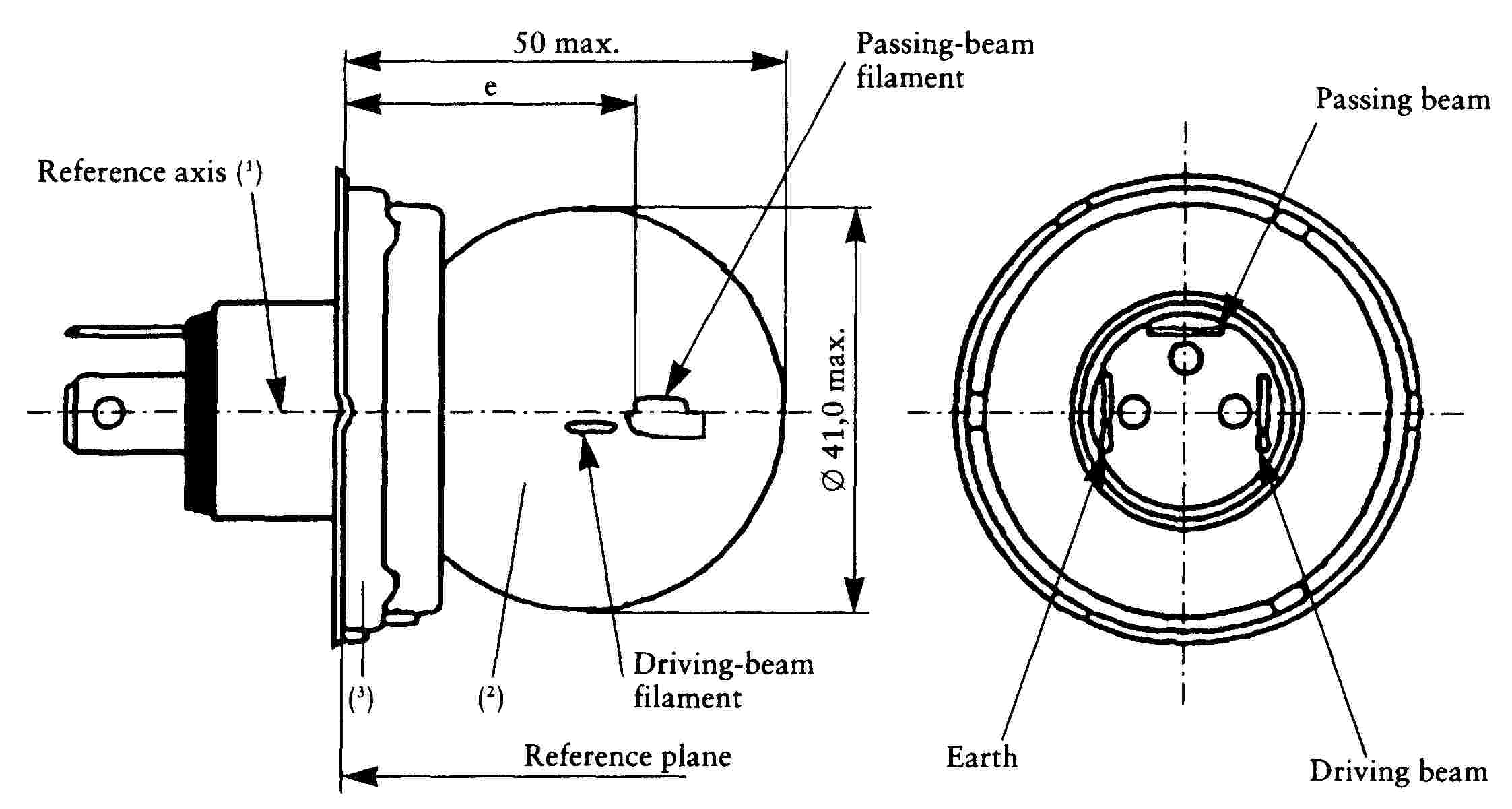
The drawings are intended only to illustrate the essential dimensions of the filament lamp
|
Electrical and photometric characteristics |
|||||||||
|
Filament lamps of normal production |
Standard filament lamp |
||||||||
|
Rated values |
Volts |
6 (1) |
12 (1) |
24 (1) |
12 (1) |
||||
|
Watts |
45 |
40 |
45 |
40 |
55 |
50 |
45 |
40 |
|
|
Test voltage |
Volts |
6,3 |
13,2 |
28 |
13,2 |
||||
|
Objective values |
Watts |
53 max. |
47 max. |
57 max. |
51 max. |
76 max. |
69 max. |
52 + 0 % - 10 % |
46 ± 5 % |
|
Luminous flux lm |
720 min. |
570 ± 15 % |
860 min. |
675 ± 15 % |
1 000 min. |
860 ± 15 % |
|||
|
Reference luminous flux at approximately 12 V |
700 |
450 |
|||||||
|
(1) The values indicated on the left and on the right refer to the driving-beam filament and the passing-beam filament respectively. |
|||||||||
SHEET R2/2
Position and dimensions of shield and filaments

The drawings are not mandatory with respect to the design of the shield and filaments.
SHEET R2/3
|
Filaments and shield position and dimensions (1) |
||||||
|
Dimensions in mm |
Tolerance |
|||||
|
Filament lamps of normal production |
Standard filament lamp |
|||||
|
6 V12 V24 V |
12 V |
|||||
|
a |
0,60 |
± 0,35 |
± 0,15 |
|||
|
b1/30,0 (2) b1/33,0 |
0,20 b1/30,0 mv (3) |
± 0,35 |
± 0,15 |
|||
|
b2/30,0 (2) b2/33,0 |
0,20 b2/30,0 mv (3) |
± 0,35 |
± 0,15 |
|||
|
c/30,0 (2) c/33,0 |
0,50 c/30,0 mv (3) |
± 0,30 |
± 0,15 |
|||
|
e |
6 V, 12 V 24 V |
28,5 28,8 |
± 0,35 |
± 0,15 |
||
|
f |
6 V, 12 V 24 V |
1,8 2,2 |
± 0,40 |
± 0,20 |
||
|
g |
0 |
± 0,50 |
± 0,30 |
|||
|
h/30,0 (2) h/33,0 |
0 h/30,0 mv (3) |
± 0,50 |
± 0,30 |
|||
|
1/2 (p—q) |
0 |
± 0,60 |
± 0,30 |
|||
|
lc |
5,5 |
± 1,50 |
± 0,50 |
|||
|
γ (4) |
15o nom. |
|||||
|
Cap P45t-41 in accordance with IEC Publ. 61 (sheet 7004-95-4) |
||||||
|
(1) The position and dimensions of the shield and filaments must be checked by means of the method of measurement as described in IEC Publication 809. (2) To be measured at the distance from the reference plane indicated in millimetres behind the stroke. (3) mv = measured value. (4) The angle γ is only for shield design and need not be checked on finished filament lamps. |
||||||
Appendix 2
Category H1 lamps
SHEET H1/1
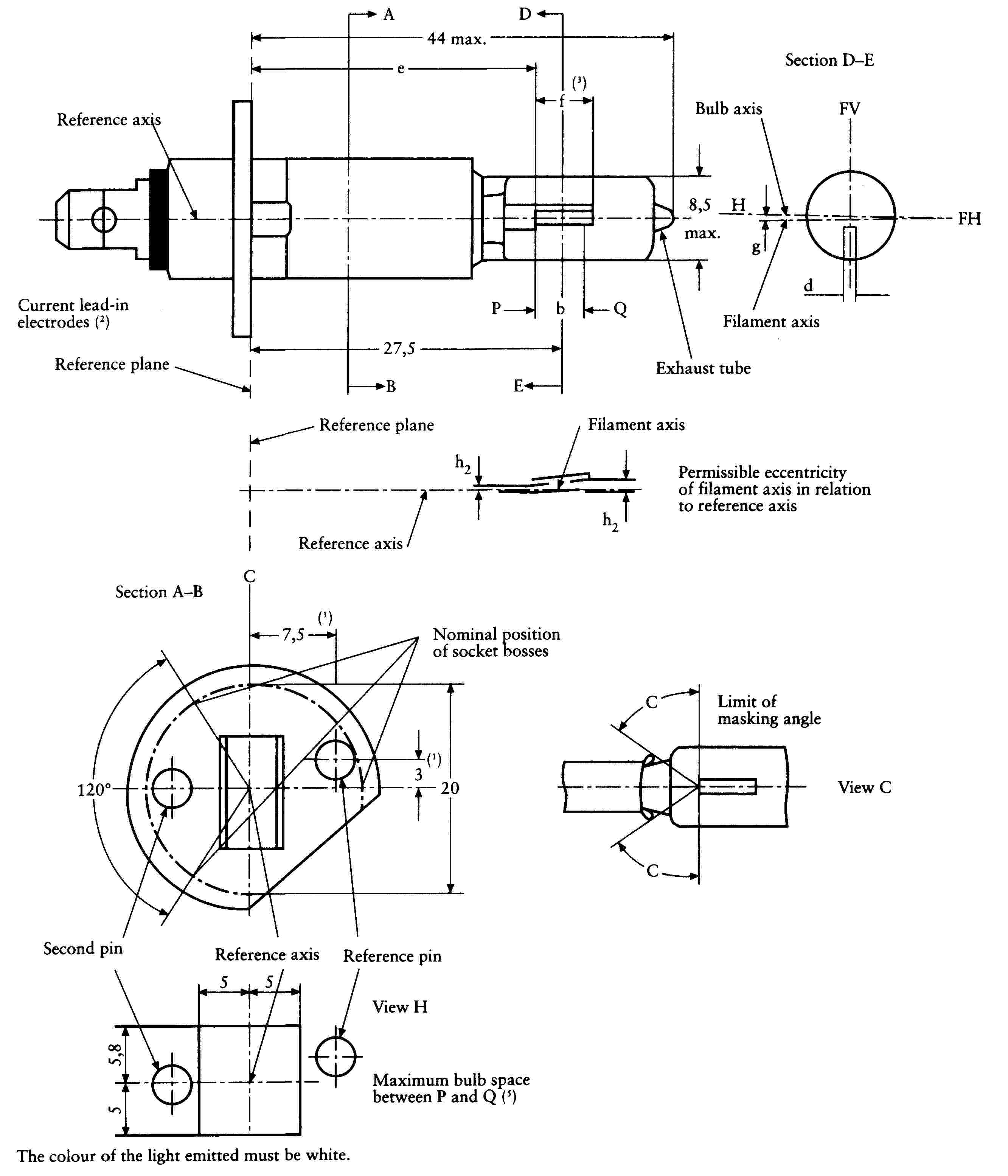
(Dimensions in mm)
The drawings are intended only to illustrate the essential dimensions of the filament lamp.
SHEET H1/2
|
Dimensions in mm |
Tolerances |
|||||
|
Filament lamps of normal production |
Standard filament lamp |
|||||
|
6 V12 V24 V |
||||||
|
b |
0,7 f |
|||||
|
e (5) (9) |
25,0 |
(8) |
± 0,15 |
|||
|
f (5) (9) |
6 V |
4,5 |
± 1,0 |
|||
|
12 V |
5,0 |
± 0,5 |
+ 0,5 0 |
|||
|
24 V |
5,5 |
± 1,0 |
||||
|
g (6) |
0,5 d (7) |
± 0,5 d |
± 0,25 d |
|||
|
h1 |
0 |
(8) |
± 0,20 (4) |
|||
|
h2 |
(8) |
± 0,25(4) |
||||
|
ε |
45o |
± 12o |
± 3o |
|||
|
Cap P 14,5s in accordance with IEC Publication 61 (sheet 7004-46-1) |
||||||
|
ELECTRICAL AND PHOTOMETRIC CHARACTERISTICS |
||||||
|
Rated values |
Volts |
6 |
12 |
24 |
12 |
|
|
Watts |
55 |
70 |
55 |
|||
|
Test voltage |
Volts |
6,3 |
13,2 |
28,0 |
||
|
Objective values |
Watts |
max. 63 |
max. 68 |
max. 84 |
max. 68 at 13,2 V |
|
|
Luminous flux lm |
1 350 |
1 550 |
1 900 |
|||
|
± % |
15 |
|||||
|
Reference luminous flux for headlamp testing: 1 150 lm at approx. 12 V. |
||||||
SHEET H1/3
(1) The reference axis is the perpendicular to the reference plane and passing through the point defined by the dimensions marked with (1).
(2) Both current lead-in electrodes must be positioned in the bulb, the longer electrode above the filament (the lamp being viewed as shown in the figure). The internal design of the lamp must then be such that stray light images and reflections are reduced to the minimum, e.g. by fitting cooling jackets over the non-coiled parts of the filament.
(3) The cylindrical portion of the bulb over length ‘f’ must be such as not to deform the projected image of the filament to such an extent as appreciably to affect the optical results.
(4) The eccentricity is measured only in the horizontal and vertical directions of the filament lamp as shown in the figure. The points to be measured are those where the projection of the outside of the end turns nearest to or furthest from the reference plane crosses the filament axis.
(5) The viewing direction is the perpendicular to the reference axis contained in the plane defined by the reference axis and the centre of the second pin of the cap.
(6) Offset of filament in relation to bulb axis measured at 27,5 mm from the reference plane.
(7) d: diameter of filament.
(8) To be checked by means of a ‘box-system’, sheet H1/4.
(9) The ends of the filament are defined as the points where, when the viewing direction is as defined in footnote 5 above, the projection of the outside of the end turns nearest to or furthest from where the reference plane crosses the reference axis (special instructions for coiled-coil filaments are under consideration).
SHEET H1/4
Screen projection requirements
This test is used to determine, by checking whether the filament is correctly positioned relatively to the reference axis and the reference plane, whether a filament lamp complies with the requirements.
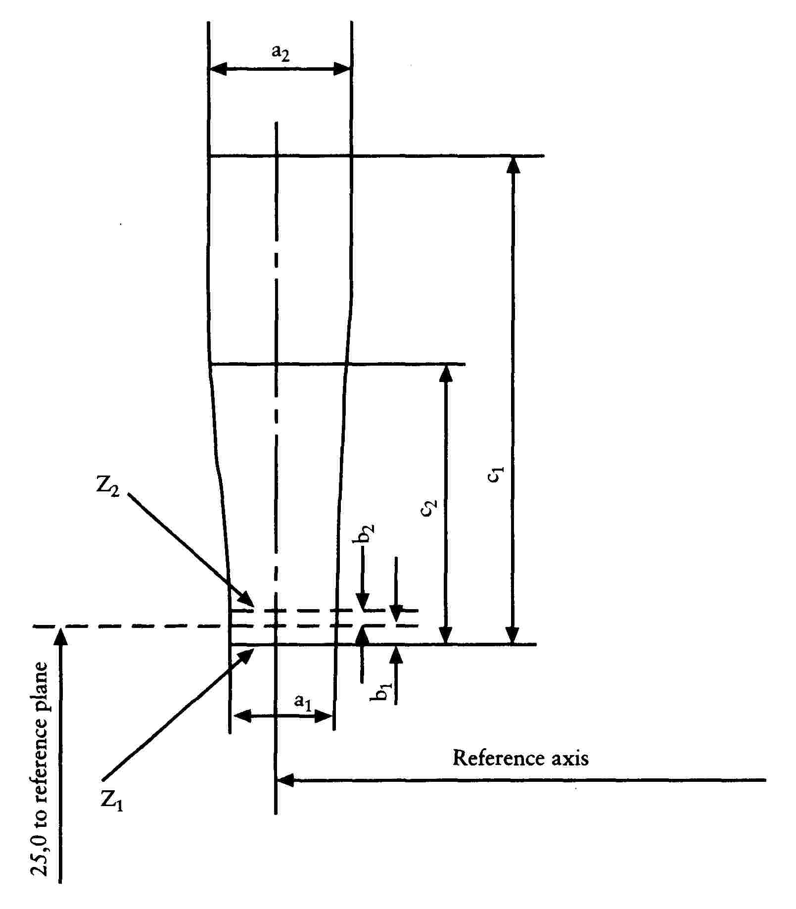
(Dimensions in millimeters)
|
a1 |
a2 |
b1 |
b2 |
c1 |
c2 |
|
|
6 V |
1,4 d |
1,9 d |
0,25 |
6 |
3,5 |
|
|
12 V |
6 |
4,5 |
||||
|
24 V |
7 |
4,5 |
||||
d = diameter of filament
The beginning of the filament as defined on sheet H1/1, footnote 2, must lie between lines Z1 and Z2.
The filament position is checked solely in directions FH and FV as shown on sheet H1/1.
The filament must lie entirely within the limits shown.
Appendix 3
Category H2 lamps
SHEET H2/1
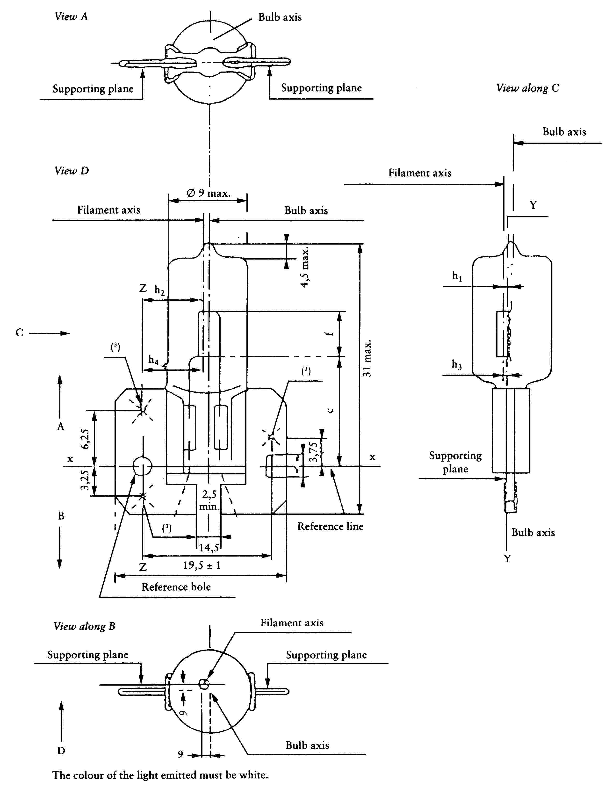
(Dimensions in mm)
The drawings are intended only to illustrate the essential dimensions of the filament lamp.
SHEET H2/2
|
Dimensions in mm |
Tolerances |
|||||
|
Filament lamp of normal production |
Standard filament lamp |
|||||
|
6 V12 V24 V |
||||||
|
e (6) |
12,25 |
(5) |
± 0,15 |
|||
|
f (6) |
6 V |
4,5 |
± 1,0 |
|||
|
12 V |
5,5 |
± 0,50 |
||||
|
24 V |
||||||
|
g (1) (2) |
0,5 d |
± 0,5 d |
± 0,25 d |
|||
|
h1 (2) |
7,1 |
(5) |
± 0,20 |
|||
|
h2 (4) |
(5) |
± 0,25 |
||||
|
h3 (1) (2) |
0,5 d |
(5) |
± 0,20 |
|||
|
h4 (1) (4) |
(5) |
± 0,25 |
||||
|
Cap X 511 in accordance with IEC Publication 61 (sheet 7004-99-2) |
||||||
|
ELECTRICAL AND PHOTOMETRIC CHARACTERISTICS |
||||||
|
Rated values |
Volts |
6 |
12 |
24 |
12 |
|
|
Watts |
55 |
70 |
55 |
|||
|
Test voltage |
Volts |
6,3 |
13,2 |
28,0 |
||
|
Objective values |
Watts |
max. 63 |
max. 68 |
max. 84 |
max. 68 at 13,2 V |
|
|
Luminous flux lm |
1 300 |
1 800 |
2 150 |
|||
|
± % |
15 |
|||||
|
Reference luminous flux for headlamp testing: 1 300 lm at approx. 12 V. |
||||||
SHEET H2/3
(1) d: diameter of filament.
(2) These offsets must be measured in a cross-section perpendicular to the axis of the bulb and passing through that end of the filament ( 51 ) which is nearer to the cap.
(3) The three crosses on the supporting plane show the positions of the three bosses defining this plane on the holder. Within a circle 3 mm in diameter centred on these points there must be no apparent deformation and no notches affecting the positioning of the filament lamp.
(4) These offsets must be measured in a cross-section perpendicular to the axis of the bulb and passing through that end of the filament (51) which is further from the cap.
(5) To be checked by means of a ‘box-system’, sheet H2/4.
(6) The ends of the filament are defined as the points where, when the viewing direction is as defined by ‘D’ (sheet H2/1), the projection of the outside of the end turns nearest to or furthest from the cap crosses a line parallel to and at a distance of 7,1 mm from line ZZ (special instructions for coiled-coil filaments are under consideration).
SHEET H2/4
Screen projection requirements
This test is used to determine, by checking whether a filament is correctly positioned relatively to the references axes x-x, y-y and z-z ( 52 ), whether a filament lamp complies with the requirements.
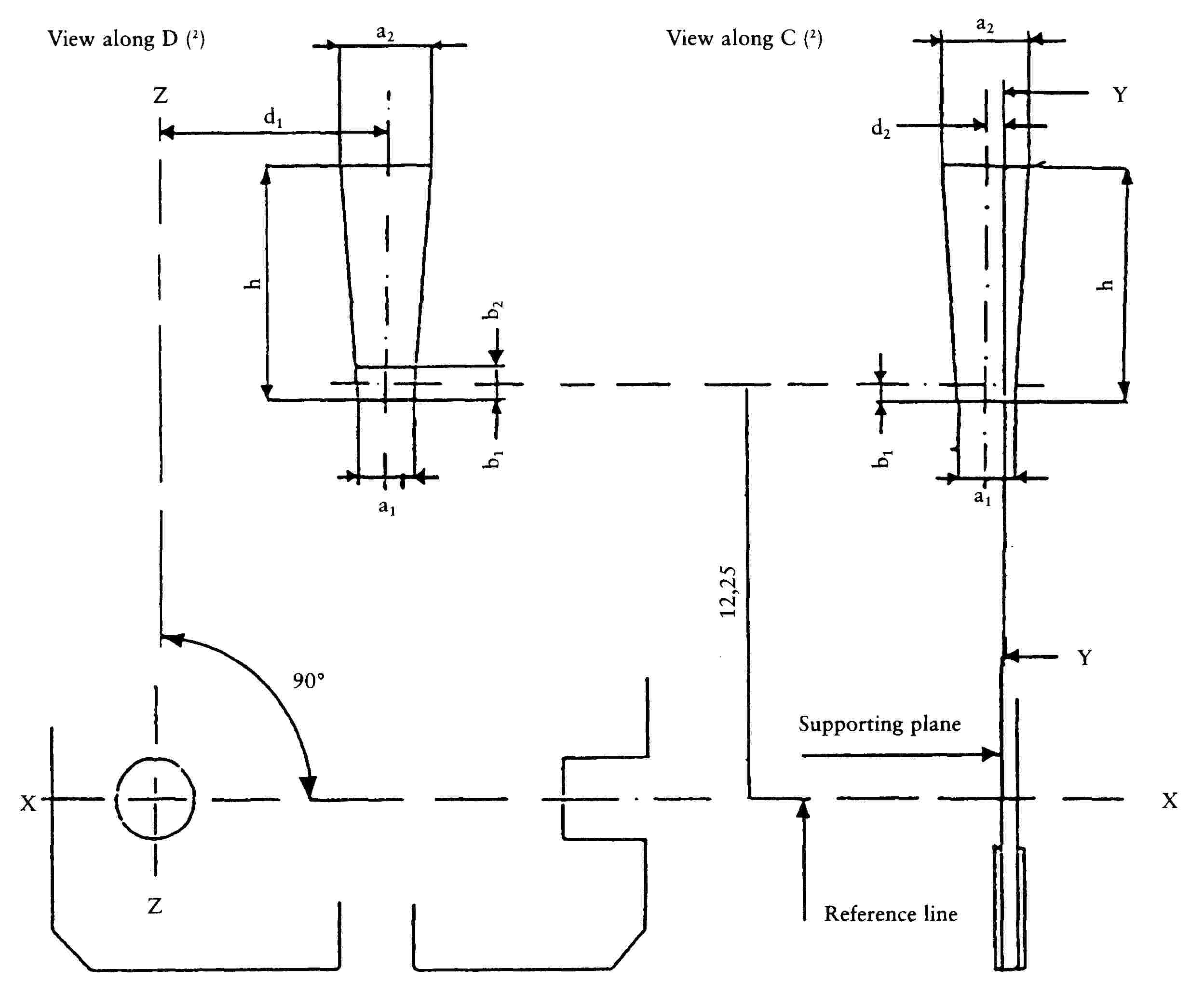
(Dimensions in millimeters)
The end of the filament ( 54 ) which is nearer to the cap must lie between b1 and b2. The filament must lie entirely within the limits shown.
|
6 V |
12 V |
24 V |
|
|
a1 |
d + 0,50 |
d + 1,0 |
|
|
a2 |
d + 1,0 |
||
|
b1, b2 |
0,25 |
||
|
d1 |
7,1 |
||
|
d2 |
0,5 d - 0,35 |
||
|
h |
6 |
7 |
|
d = diameter of filament
Appendix 4
Category H3 lamps
SHEET H3/1

(Dimensions in millimetres)
The colour of the light emitted must be white.
SHEET H3/2
Definition: Ring centre and reference axis (2)
Filament dimensions and tolerances for standard filament lamps, see sheet H3/3
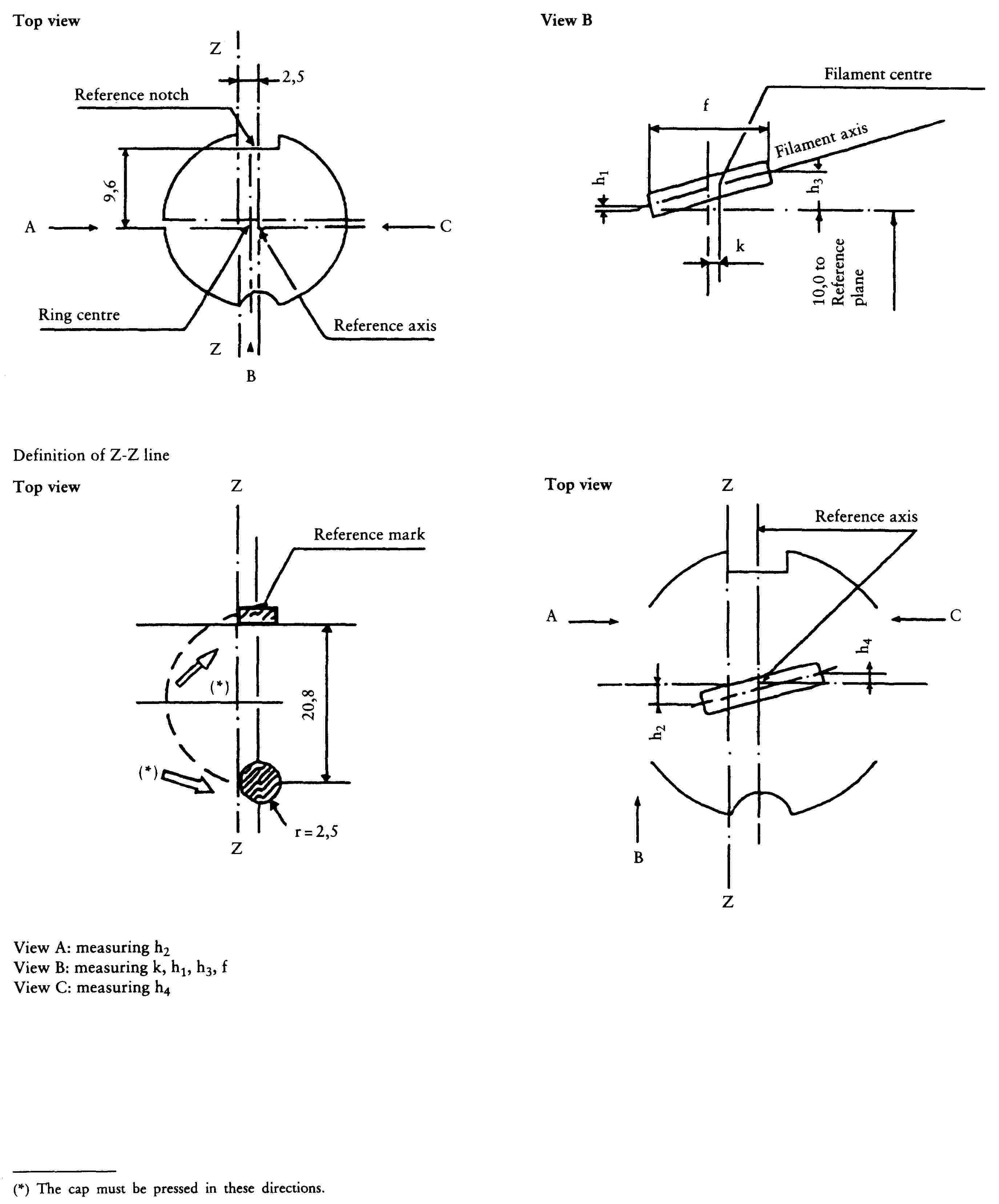
(Dimensions in millimetres)
SHEET H3/3
|
Dimensions in mm |
Filament lamps of normal production |
Standard filament lamp |
|||
|
6 V |
12 V |
24 V |
|||
|
e |
18,0 (5) |
18,0 |
|||
|
f (7) |
3,0 min |
4,0 min |
5,0 ± 0,50 |
||
|
k |
(5) |
0 ± 0,20 |
|||
|
h1 |
0 ± 0,15 (6) |
||||
|
h3 |
|||||
|
h2 |
0 ± 0,25 (6) |
||||
|
h4 |
|||||
|
Cap PK 22s in accordance with IEC Publication 61 (sheet 7004-47-2) |
|||||
|
ELECTRICAL AND PHOTOMETRIC CHARACTERISTICS |
|||||
|
Rated values |
Volts |
6 |
12 |
24 |
12 |
|
Watts |
55 |
70 |
55 |
||
|
Test voltage |
Volts |
6,3 |
13,2 |
28,0 |
|
|
Objective values |
Watts |
max 63 |
max 68 |
max 84 |
max 68 at 13,2 V |
|
luminous flux lm |
1 050 |
1 450 |
1 750 |
||
|
± % |
15 |
||||
|
Reference luminous flux for headlamp testing: 1 100 lm at approx. 12 V. |
|||||
SHEET H3/4
(1) The distortion of the base-end portion of the bulb must not be visible from any direction outside the obscuration angle of 80o max. The shields must produce no inconvenient reflections. The angle between the reference axis and the plane of each shield, measured on the bulb side, must not exceed 90o.
(2) The permissible deviation of the ring centre from the reference axis is 0,5 mm in the direction perpendicular to the Z-Z line and 0,05 mm in the direction parallel to the Z-Z line.
(3) Minimum length above the height of the light-emitting centre (‘e’) over which the bulb must be cylindrical.
(4) No part of the spring and no component of the lamp-holder may bear on the prefocus ring elsewhere than outside the rectangle shown in discontinuous outline.
(5) These dimensions of lamps of normal production must be checked by means of a ‘box-system’ (sheet H3/5).
(6) For standard filament lamps the points to be measured are those where the projection of the outside of the end turns crosses the filament axis.
(7) the positions of the first and the last turn of the filament are defined by the intersections of the outside of the first and the outside of the last light-emitting turn, respectively, with the plane parallel to and 13 mm distant from the reference plane (additional instructions for coiled-coil filaments are under consideration).
SHEET H3/5
Screen projection requirements
This test is used to determine, by checking whether the filament is correctly positioned relatively to the reference axis and the reference plane, whether a filament lamp complies with the requirements.
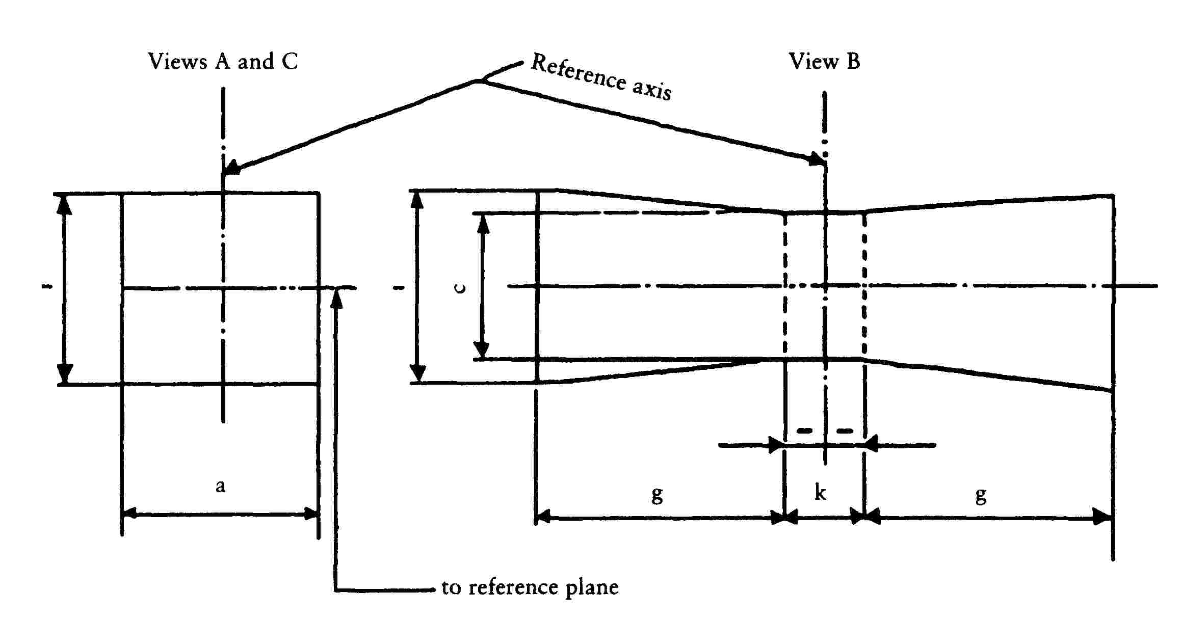
(Dimensions in millimetres)
|
a |
c |
k |
g |
|
|
6 V |
1,8 d |
1,6 d |
1,0 |
2,0 |
|
12 V |
2,8 |
|||
|
24 V |
2,9 |
d = diameter of the filament
The filament must lie entirely within the limits shown.
The centre of the filament must lie within the limits of dimension k.
Appendix 5
Category H4 lamps
SHEET H4/1

(Dimensions in millimetres)
The drawings are not mandatory; their sole purpose is to show which dimensions must be verified.
|
Reference |
Dimension |
Tolerance |
||
|
12 V |
24 V |
12 V |
24 V |
|
|
+ 0,45 |
||||
|
e |
28,5 |
29,0 |
- 0,25 |
± 0,35 |
|
p |
28,95 |
29,25 |
— |
— |
|
m (1) |
max. 60,0 |
— |
||
|
n (1) |
max. 34,5 |
— |
||
|
s (2) |
45,0 |
— |
||
|
α (3) |
max. 40o |
— |
||
SHEET H4/2
Characteristics
|
Filament lamps of normal production |
Standard filament lamps |
||||||
|
Rated values |
Volts |
12 (4) |
24 (4) |
12 (4) |
|||
|
Watts |
60 |
55 |
75 |
70 |
60 |
55 |
|
|
Test voltage |
Volts |
13,2 |
28 |
||||
|
Objective values |
Watts |
max. 75 |
max. 68 |
max. 85 |
max. 80 |
max. 75 at 13,2 V |
max. 68 at 13,2 V |
|
Luminous flux lm |
1 650 |
1 000 |
1 900 |
1 200 |
|||
|
± % |
15 |
||||||
|
Reference luminous flux at approximately 12 V lm |
1 250 |
750 |
|||||
|
Cap P43t-38 in accordance with IEC Publication 61 (sheet 7004-39-2) |
|||||||
SHEET H4/3

SHEET H4/4
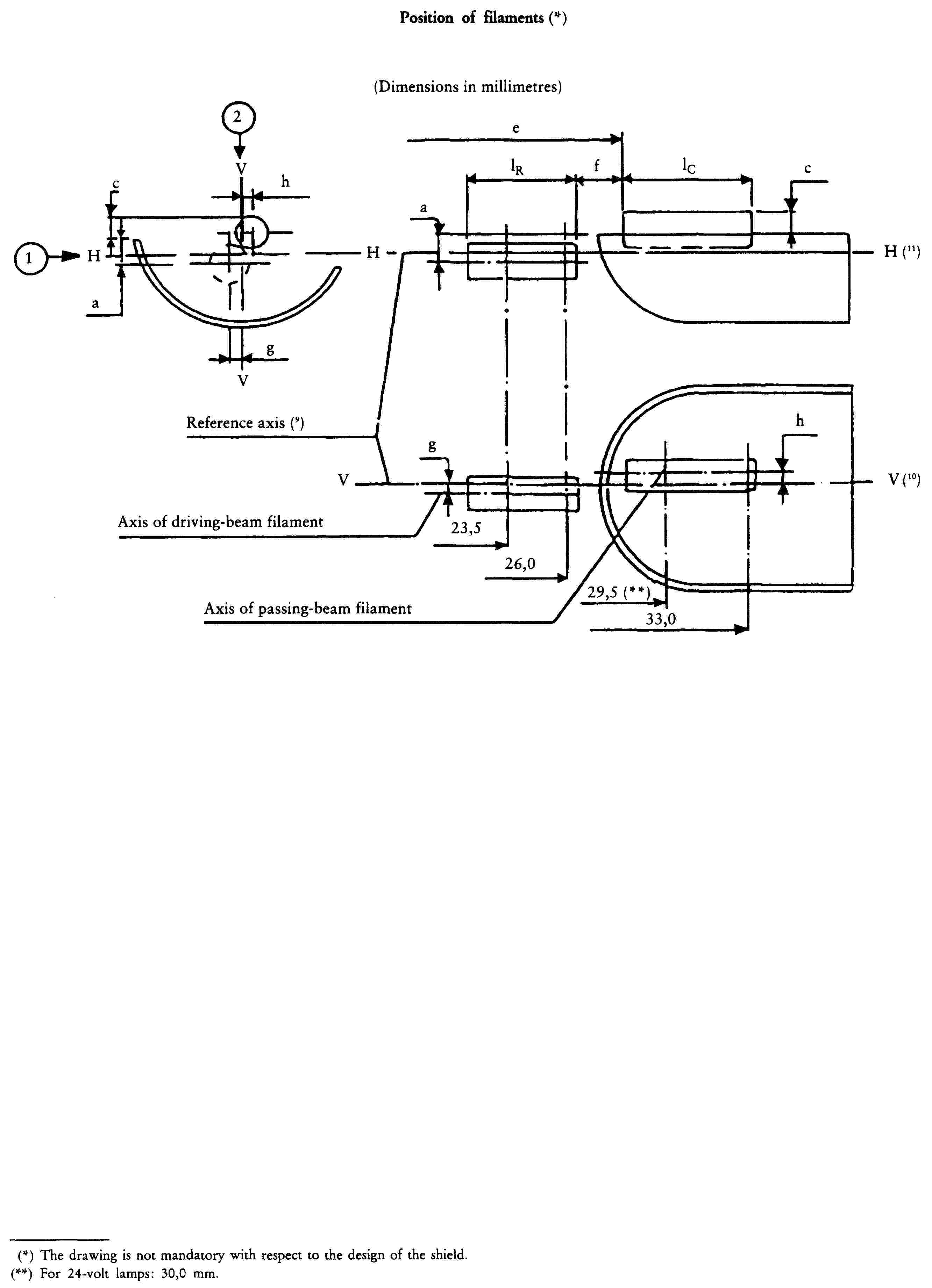
SHEET H4/5
ADDITIONAL EXPLANATIONS TO SHEETS H4/3 AND H4/4
The dimensions below are measured in three directions:
![]() for dimensions a, b1, c, d, e, f, lR and lC;
for dimensions a, b1, c, d, e, f, lR and lC;
![]() for dimensions g, h, p and q;
for dimensions g, h, p and q;
![]() for dimensions b2.
for dimensions b2.
Dimensions p and q are measured in a plane parallel to and 33 mm away from the reference plane.
Dimensions b1, b2, c and h are measured in planes parallel to and 29,5 mm (30,0 mm for 24-V lamps) and 33 mm away from the reference plane.
Dimensions a and g are measured in planes parallel to and 26,0 mm and 23,5 mm away from the reference plane.
Note: For the method of measurement, see Appendix E of IEC Publication 809.
SHEET H4/6
Table of the dimensions referred to in the diagrams on sheets H4/3 and H4/4 (in mm)
|
Reference |
Dimension |
Tolerances |
||||
|
Filament lamps of normal production |
Standard filament lamp |
|||||
|
12 V |
24 V |
12 V |
24 V |
12 V |
24 V |
12 V |
|
a/26 (1) |
0,8 |
± 0,35 |
± 0,2 |
|||
|
a/23,5 (1) |
0,8 |
± 0,60 |
± 0,2 |
|||
|
b1/29,5 (1) |
30,0 (1) |
0 |
± 0,30 |
± 0,35 |
± 0,2 |
|
|
b1/33 (1) |
b1/29,5 mv (2) |
30,0 mv (2) |
± 0,30 |
± 0,35 |
± 0,15 |
|
|
b2/29,5 (1) |
30,0 (1) |
0 |
± 0,30 |
± 0,35 |
± 0,2 |
|
|
b2/33 (1) |
b2/29,5 mv (2) |
30,0 mv (2) |
± 0,30 |
± 0,35 |
± 0,15 |
|
|
c/29,5 (1) |
30,0 (1) |
0,6 |
0,75 |
± 0,35 |
± 0,2 |
|
|
c/33 (1) |
c/29,5 mv (2) |
30,0 mv (2) |
± 0,35 |
± 0,15 |
||
|
d |
min. 0,1 |
— |
— |
|||
|
e (7) |
28,5 |
29,0 |
+ 0,35 - 0,25 |
± 0,35 |
+ 0,2 - 0,0 |
|
|
f (5) (6) (8) |
1,7 |
2,0 |
+ 0,50 - 0,30 |
± 0,40 |
+ 0,3 - 0,1 |
|
|
g/26 (1) |
0 |
± 0,5 |
± 0,3 |
|||
|
g/23,5 (1) |
0 |
± 0,7 |
± 0,3 |
|||
|
h/29,5 (1) |
30,0 (1) |
0 |
± 0,5 |
± 0,3 |
||
|
h/33 (1) |
h/29,5 mv (2) |
30,0 mv (2) |
± 0,35 |
± 0,2 |
||
|
lR (5) (8) |
4,5 |
5,25 |
± 0,8 |
± 0,4 |
||
|
lC (5) (6) |
5,5 |
5,25 |
± 0,5 |
± 0,8 |
± 0,35 |
|
|
p/33 (1) |
Depends on the shape of the shield |
— |
— |
|||
|
q/33 (1) |
|
± 0,6 |
± 0,3 |
|||
|
(1) Dimension to be measured at the distance from the reference plane indicated in mm after the stroke. (2) ‘29,5 mv’ or ‘30,0 mv’ means the value measured at a distance of 29,5 mm or 30,0 mm from the reference plane. |
||||||
SHEET H4/7
(1) ‘m’ and ‘n’ denote the maximum dimensions of the lamp
(2) It must be possible to insert the lamp into a cylinder of diameterr ‘s’ concentric with the reference axis and limited at one end by a plane parallel to and 20 mm distant from the reference plane and at the other end by a hemisphere of radius
![]()
(3) The obscuration must extend at least as far as the cylindrical part of the bulb. It must also overlap the internal shield when the latter is viewed in a direction perpendicular to the reference axis. The effect sought by obscuration may also be achieved by other means.
(4) The values indicated in the left-hand column relate to the driving beam. Those indicated in the right-hand column relate to the passing beam.
(5) The end turns of the filaments are defined as being the first luminous turn and the last luminous turn that are at substantially the correct helix angle. For coiled-coil filaments, the turns are defined by the envelope of the primary coil.
(6) For the passing-beam filament the points to be measured are the intersections, seen in direction![]() , of the lateral edge of the shield with the outside of the end turns defined under footnote 5.
, of the lateral edge of the shield with the outside of the end turns defined under footnote 5.
(7) ‘e’ denotes the distance from the reference plane to the beginning of the passing-beam filament as defined above.
(8) For the driving beam filament the points to be measured are the intersections, seen in direction![]() , of a plane, parallel to plane HH and situated at a distance of 0,8 mm below it, with the end turns defined under footnote 5.
, of a plane, parallel to plane HH and situated at a distance of 0,8 mm below it, with the end turns defined under footnote 5.
(9) The reference axis is the line perpendicular to the reference plane and passing through the centre of the circle of diameter ‘M’ (see sheet H4/1).
(10) Plane VV is the plane perpendicular to the reference plane and passing through the reference axis and through the intersection of the circle of diameter ‘M’ with the axis of the reference pin.
(11) Plane HH is the plane perpendicular to both the reference plane and plane VV and passing through the reference axis.
Appendix 6
Category HS1
SHEET HS1/1
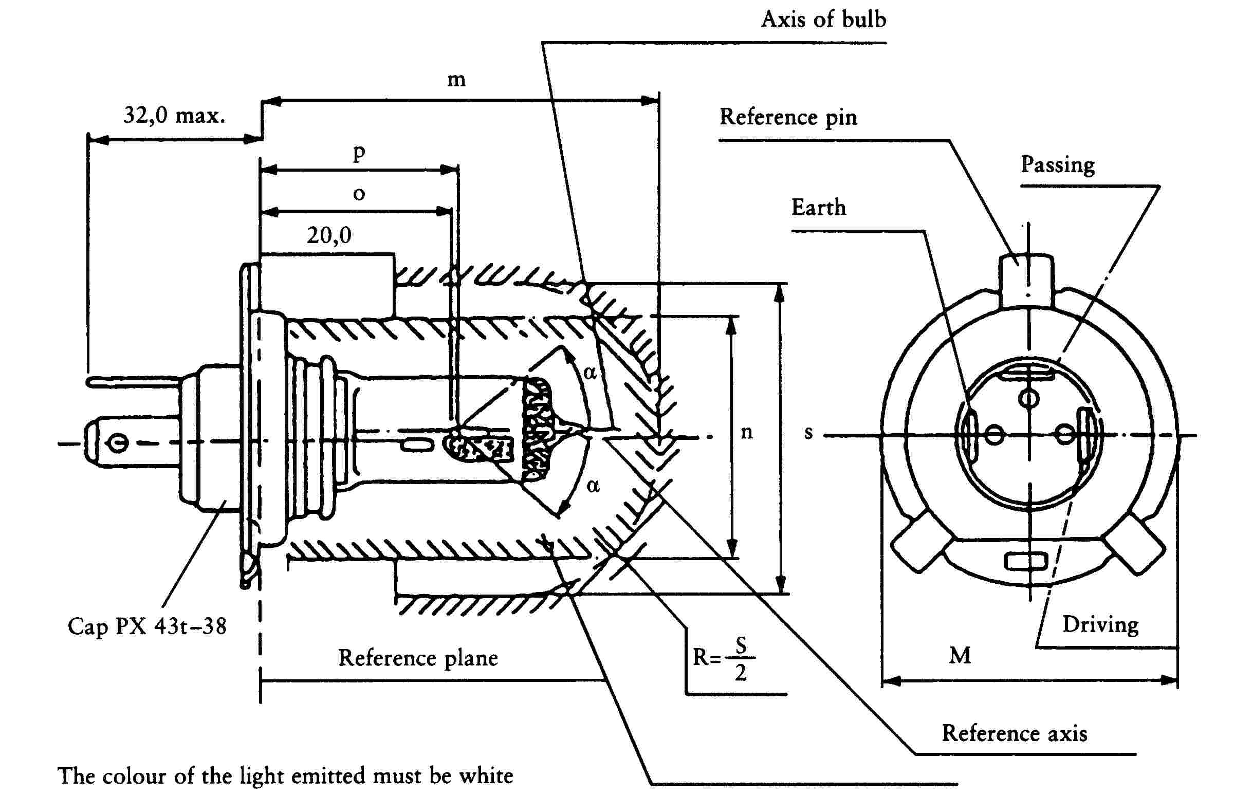
(Dimensions in millimetres)
The drawings are not mandatory; their sole purpose is to show which dimensions must be verified.
|
Reference |
Dimension |
Tolerance |
||
|
6 V |
12 V |
6 V |
12 V |
|
|
o |
28,5 |
+ 0,45 - 0,25 |
||
|
p |
28,95 |
— |
||
|
m (1) |
max. 60,0 |
— |
||
|
n (1) |
max. 34,5 |
— |
||
|
s (2) |
45,0 |
— |
||
|
α (3) |
max. 40o |
— |
||
SHEET HS1/2
Characteristics
|
Filament lamps of normal production |
Standard filament lamps |
||||||
|
Rated values |
Volts |
6 (4) |
12 (4) |
12 (4) |
|||
|
Watts |
35 |
35 |
35 |
35 |
35 |
35 |
|
|
Test voltage |
Volts |
6,3 |
13,2 |
||||
|
Objective values |
Watts |
35 |
35 |
35 |
35 |
35 at 13,2 V |
35 at 13,2 V |
|
± % |
5 |
5 |
5 |
5 |
5 |
5 |
|
|
Luminous flux lm |
700 |
440 |
825 |
525 |
|||
|
± % |
15 |
||||||
|
Reference luminous flux at approximately 12 V lm |
700 |
450 |
|||||
|
Cap PX43t-38 in accordance with IEC Publication 61 (sheet 7004-34-1). |
|||||||
SHEET HS1/3
Table of the dimensions referred to in the diagrams on sheets HS1/4 and HS1/5 (in mm)
|
Reference |
Dimension |
Tolerances |
||||
|
Filament lamps of normal production |
Standard filament lamp |
|||||
|
6 V |
12 V |
6 V |
12 V |
6 V |
12 V |
12 V |
|
a/26 (1) |
0,8 |
± 0,35 |
± 0,2 |
|||
|
a/25 (1) |
0,8 |
± 0,55 |
± 0,2 |
|||
|
b1/29,5 (1) |
0 |
± 0,35 |
± 0,2 |
|||
|
b1/33 (1) |
b1/29,5 mv |
± 0,35 |
± 0,15 |
|||
|
b2/29,5 (1) |
0 |
± 0,35 |
± 0,2 |
|||
|
b2/33 (1) |
b2/29,5 mv |
± 0,35 |
± 0,15 |
|||
|
c/29,5 (1) |
0,5 |
± 0,35 |
± 0,2 |
|||
|
c/31 (1) |
c/29,5 mv |
± 0,30 |
± 0,15 |
|||
|
d |
min. 0,1 max. 1,5 |
— |
— |
|||
|
e (7) |
28,5 |
+ 0,45 - 0,25 |
+ 0,2 - 0,0 |
|||
|
f (5) (6) (8) |
1,7 |
+ 0,50 - 0,30 |
+ 0,3 - 0,1 |
|||
|
g/25 (1) |
0 |
± 0,5 |
± 0,3 |
|||
|
g/25 (1) |
0 |
± 0,7 |
± 0,3 |
|||
|
h/29,5 (1) |
0 |
± 0,5 |
± 0,3 |
|||
|
h/31 (1) |
h/29,5 |
± 0,30 |
± 0,2 |
|||
|
lR (5) (8) |
3,5 |
4,0 |
± 0,8 |
± 0,4 |
||
|
lC (5) (6) |
3,3 |
4,5 |
± 0,8 |
± 0,35 |
||
|
p/33 (1) |
Depends on the shape of the shield |
— |
— |
|||
|
q/33 (1) |
|
± 0,6 |
± 0,3 |
|||
|
(1) Dimension to be measured at the distance from the reference plane indicated in mm after the stroke. |
||||||
SHEET HS1/4
Position of filaments ( 55 )

(Dimensions in millimetres)
SHEET HS1/5
Position of shield ( 56 )

(Dimensions in millimetres)
SHEET HS1/6
ADDITIONAL EXPLANATION TO SHEETS HS1/4 AND HS1/5
The dimensions below are measured in three directions:
![]() for dimensions a, b1, c, d, e, f, lR and lC;
for dimensions a, b1, c, d, e, f, lR and lC;
![]() for dimensions g, h, p and q;
for dimensions g, h, p and q;
![]() for dimension b2.
for dimension b2.
Dimension p and q are measured in a plane parallel to 33 mm away from the reference plane.
Dimensions b1 and b2 are measured in planes parallel to and 29,5 mm and 33 mm away from the reference plane.
Dimensions a and g are measured in planes parallel to and 25 mm and 36 mm away from the reference plane.
Dimensions c and h are measured in planes parallel to and 29,5 mm and 31 mm away from the reference plane.
SHEET HS1/7
(1) ‘m’ and ‘n’ denote the maximum dimensions of the lamp.
(2) it must be possible to insert the lamp into a cylinder of diameter ‘s’ concentric with the reference axis and limited at one end by a plane parallel to and 20 mm distant from the reference plane and at the other end by a hemisphere of radius
![]()
(3) The obscuration must extend at least as far as the cylindrical part of the bulb. It must also overlap the internal shield when the latter is viewed in a direction perpendicular to the reference axis. The effect sought by obscuration may also be achieved by other means.
(4) The values indicated in the left-hand column relate to the driving beam. Those indicated in the right-hand column relate to the passing beam.
(5) The end turns of the filaments are defined as being the first luminous turn and the last luminous turn that are at substantially the correct helix angle. For coiled-coil filaments, the turns are defined by the envelope of the primary coil.
(6) For the passing-beam filament the points to be measured are the intersections, seen in direction![]() , of the lateral edge of the shield with the outside of the end turns defined under footnote 5.
, of the lateral edge of the shield with the outside of the end turns defined under footnote 5.
(7) ‘e’ denotes the distance from the reference plane to the beginning of the passing-beam filament as defined above.
(8) For the driving beam filament the points to be measured are the intersections, seen in direction![]() , of a plane, parallel to plane HH and situated at a distance of 0,8 mm below it, with the end turns defined under footnote 5.
, of a plane, parallel to plane HH and situated at a distance of 0,8 mm below it, with the end turns defined under footnote 5.
(9) The reference axis is the line perpendicular to the reference plane and passing through the centre of the circle of diameter ‘M’ (see sheet HS1/1).
(10) Plane VV is the plane perpendicular to the reference plane and passing through the reference axis and through the intersection of the circle of diameter ‘M’ with the axis of the reference pin.
(11) Plane HH is the plane perpendicular to both the reference plane and plane VV and passing through the reference axis.
Appendix 7
Category HB3
SHEET HB3/1

(Dimensions in millimetres)
The drawings are intended only to illustrate essential dimensions of the filament lamp
SHEET HB3/2
|
Dimensions in mm (11) |
Tolerances |
||
|
Filament lamps of normal production |
Standard filament lamp |
||
|
e (8) (4) |
31,5 |
(7) |
± 0,16 |
|
f (8) (4) |
5,1 |
(7) |
± 0,16 |
|
h1, h2 |
0 |
(7) |
± 0,15 (3) |
|
h3 |
0 |
(7) |
± 0,08 (3) |
|
γ1 (5) |
45o min. |
— |
— |
|
γ2 (5) |
52o min. |
— |
— |
|
Cap P 20d in accordance with IEC Publication 61 (sheet 7004-31-1) |
|||
|
ELECTRICAL AND PHOTOMETRIC CHARACTERISTICS |
|||
|
Rated values |
Volts |
12 |
12 |
|
Watts |
60 |
60 |
|
|
Test voltage |
Volts |
13,2 |
13,2 |
|
Objective values |
Watts |
73 max. |
73 max. |
|
Luminous flux lm |
1 860 |
||
|
± % |
12 |
||
|
Reference luminous flux for headlamp testing: 1 300 lm at approx. 12 V |
|||
SHEET HB3/3
(1) The reference plane is the plane formed by the meeting points of the cap-holder fit.
(2) The reference axis is the axis perpendicular to the reference plane and concentric with the 17,46 mm diameter of the cap.
(3) The eccentricity is measured only in viewing directions ( 57 ) A and B as shown in the figure on Sheet HB3/1. The points to be measured are those where the projection of the outside of the end turns nearest to or furthest from the reference plane crosses the filament axis.
(4) The viewing direction is direction (57) B as shown in the figure on Sheet HB3/1.
(5) Glass bulb periphery must be optically distortion-free axially within the angles γ1 and γ2. This requirement applies to the whole bulb circumference within the angles γ1 and γ2. The colour of the light emitted must be white.
(6) Glass bulb and supports must not exceed the envelope and not interfere with insertion past the lamp key. The envelope is concentric to the reference axis.
(7) To be checked by means of a ‘box-system’, Sheet HB3/4 (57) .
(8) The ends of the filament are defined as the points where, when the viewing direction (57) as defined in footnote 4 above, the projection of the outside of the end turns crosses the filament axis.
(9) The keyway is mandatory.
(10) The filament lamp must be rotated in the measuring holder until the reference lug contacts plane C of the holder.
(11) Dimensions must be checked with O-ring removed.
SHEET HB3/4
Screen projection requirements
This test is used to determine, by checking whether the filament is correctly positioned relatively to the reference axis and the reference plane, whether a filament lamp complies with the requirements.
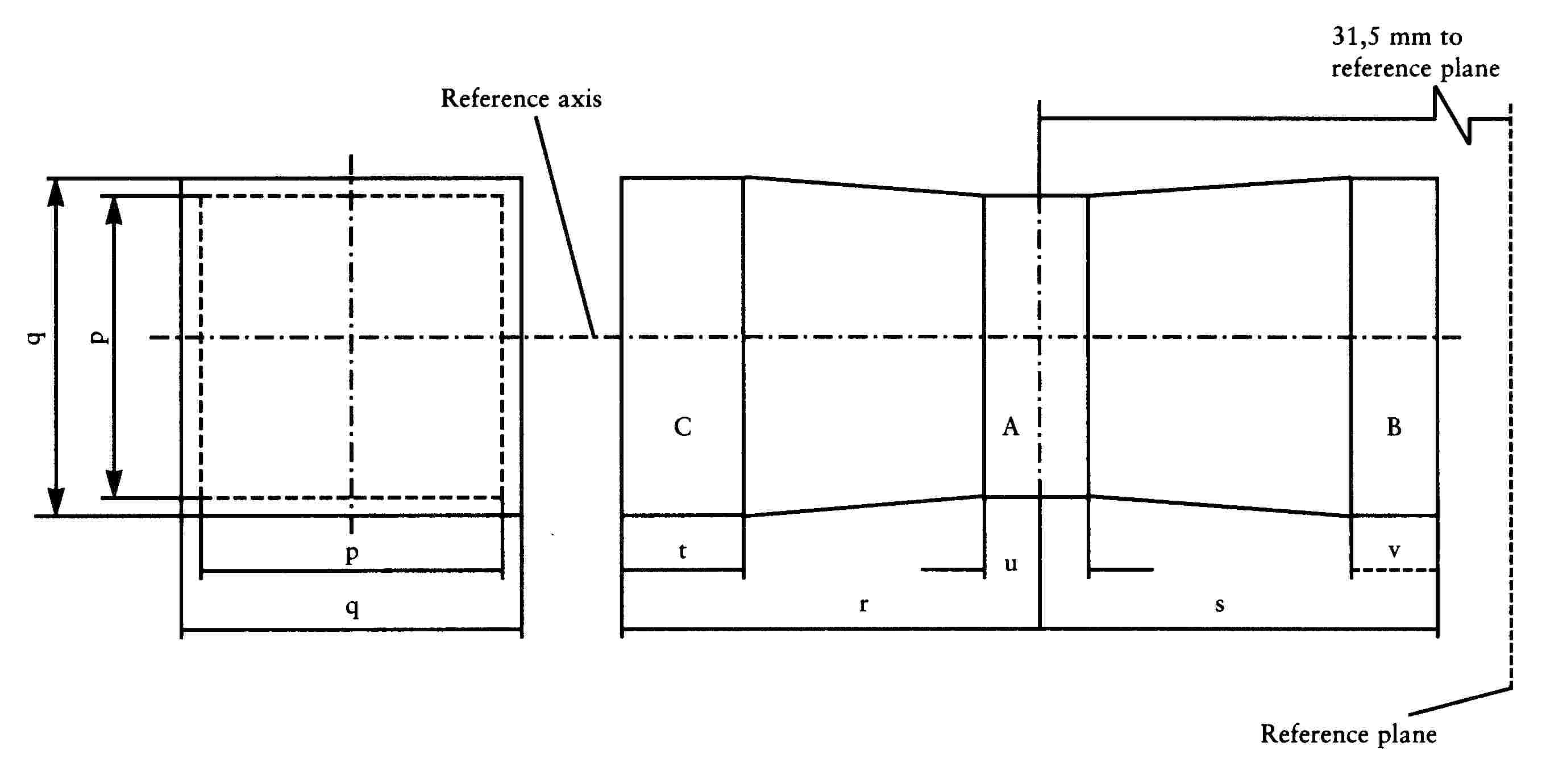
(Dimensions in millimetres)
|
p |
q |
r |
s |
t |
u |
v |
|
|
12 V |
1,3 d |
1,6 d |
3,0 |
2,9 |
0,9 |
0,4 |
0,7 |
d is the diameter of the filament
The filament position is checked solely in directions A and B als shown on sheet HB3/1.
The beginning of the filament as defined on sheet HB3/3, note 8, must be in volume ‘B’ and the end of the filament in volume ‘C’.
The filament must lie entirely within the limits shown. Volume ‘A’ does not involve any filament centre requirement.
Appendix 8
Category HB4
SHEET HB4/1
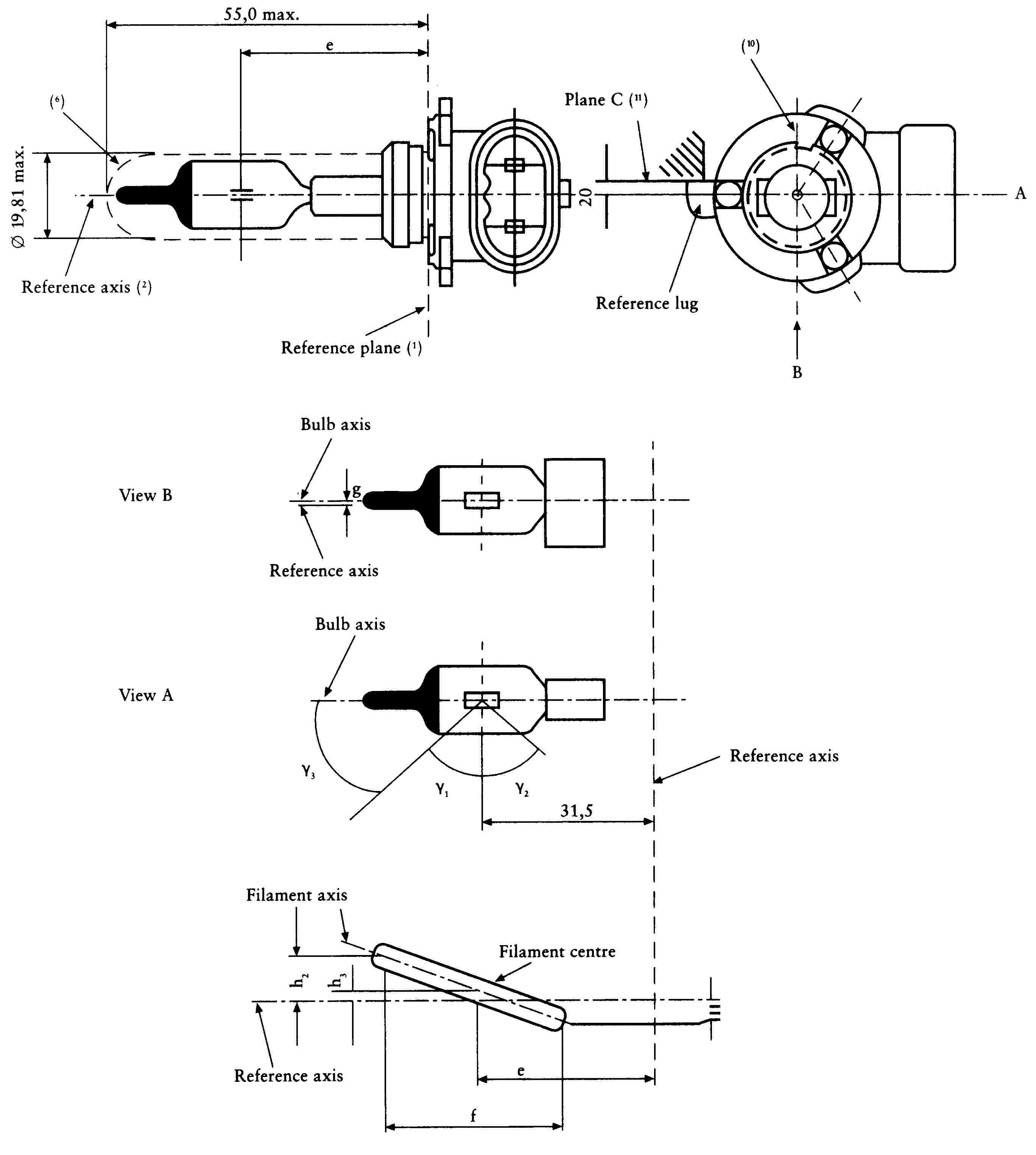
(Dimensions in millimetres)
The drawings are intended only to illustrate the essential dimensions of the filament lamp
SHEET HB4/2
|
Dimensions in mm (12) |
Tolerances |
||
|
Filament lamps of normal production |
Standard filament lamp |
||
|
e (4) (9) |
31,5 |
(8) |
± 0,16 |
|
f (4) (9) |
5,1 |
(8) |
± 0,16 |
|
h1, h2 |
0 |
(8) |
± 0,15 (3) |
|
h3 |
0 |
(8) |
± 0,08 (3) |
|
g (4) |
0,75 |
± 0,5 |
± 0,3 |
|
γ1 (5) |
50o min. |
— |
— |
|
γ2 (5) |
52o min. |
— |
— |
|
γ3 (7) |
45o |
± 5o |
± 5o |
|
Cap P 22d in accordance with IEC Publication 61 (sheet 7004-32-1) |
|||
|
ELECTRICAL AND PHOTOMETRIC CHARACTERISTICS |
|||
|
Rated Values |
Volts |
12 |
12 |
|
Watts |
51 |
51 |
|
|
Test voltage |
Volts |
13,2 |
13,2 |
|
Objective values |
Watts |
62 max. |
62 max. |
|
luminous flux lm |
1 095 |
||
|
± % |
15 |
||
|
Reference luminous flux for headlamp testing: 825 lm at approx. 12 V. |
|||
SHEET HB4/3
(1) The reference plane is the plane formed by the meeting points of the cap-holder fit.
(2) The reference axis is the axis perpendicular to the reference plane and concentric with the 19,46 mm diameter of the cap.
(3) The eccentricity is measured only in viewing directions ( 58 ) A and B as shown in the figure on Sheet HB4/1. The points to be measured are those where the projection of the outside of the end turns nearest to or furthest from the reference plane crosses the filament axis.
(4) The viewing direction is direction (58) B as shown in the figure on Sheet HB4/1.
(5) Glass bulb periphery must be optically distortion-free axially within the angles γ1 and γ2. This requirement applies to the whole bulb circumference within the angles γ1 und γ2. The colour of the light emitted must be white.
(6) Glass bulb and supports must not exceed the envelope and not interfere with insertion past the lamp key. The envelope is concentric to the reference axis.
(7) The obscuration must extend at least to angle γ3 and be at least as far as the undistorted part of the bulb defined by angle γ1.
(8) To be checked by means of a ‘box-system’, Sheet HB4/4 (58) .
(9) The ends of the filament are defined on the points where, when the viewing direction (58) as defined in footnote 4 above, the projection of the outside of the end turns crosses the filament axis.
(10) The keyway is mandatory.
(11) The filament lamp must be rotated in the measuring holder until the reference lug contacts plane C of the holder.
(12) Dimensions must be checked with O-ring removed.
SHEET HB4/4
Screen projection requirements
This test is used to determine, by checking whether the filament is correctly positioned relative to the reference axis and the reference plane, whether a filament lamp complies with the requirements.
(Dimensions in millimetres)
|
p |
q |
r |
s |
t |
u |
v |
|
|
12 V |
1,3 d |
1,6 d |
3,0 |
2,9 |
0,9 |
0,4 |
0,7 |
d is the diameter of the filament
The filament position is checked solely in directions A and B as shown on sheet HB4/1.
The beginning of the filament as defined on sheet HB4/3, note 9, must be in volume ‘B’ and the end of the filament in volume ‘C’.
The filament must lie entirely within the limits shown. Volume ‘A’ does not involve any filament centre requirement.
Appendix 9
Category H7
SHEET H7/1

Figure 1: Main drawing
(Dimensions in millimetres)
The drawings are intended only to illustrate the essential dimensions of the filament lamp
SHEET H7/2
|
Rated voltage 12 V |
|||
|
Dimensions in mm |
Tolerances |
||
|
Filament lamps of normal production |
Standard filament lamp |
||
|
e (7) |
25,0 |
(8) |
± 0,1 |
|
f (7) |
4,1 |
(8) |
± 0,1 |
|
g (10) |
0,5 |
min. |
u.c. |
|
h1 (9) |
0 |
(8) |
± 0,1 |
|
h2 (9) |
0 |
(8) |
± 0,15 |
|
γ1 (4) |
40o min. |
— |
— |
|
γ2 (4) |
50o min. |
— |
— |
|
γ3 (5) |
30o min. |
— |
— |
|
Cap PX 26d in accordance with IEC Publication 61 (sheet 7004-5-1) |
|||
|
ELECTRICAL AND PHOTOMETRIC CHARACTERISTICS |
|||
|
Rated values |
Volts |
12 |
12 |
|
Watts |
55 |
55 |
|
|
Test voltage |
Volts |
13,2 |
13,2 |
|
Objective values |
Watts |
max. 58 |
max. 58 |
|
luminous flux lm |
1 500 |
||
|
± % |
10 |
||
|
Reference luminous flux for headlamp testing: 1 100 lm at approx. 12 V. |
|||
SHEET H7/3
(1) The reference plane is defined by the points on the surface of the holder on which the three supporting bosses of the cap ring will rest.
(2) The reference axis is perpendicular to the reference plane and crosses the intersection of the two perpendiculars as indicated in figure 3 on Sheet H7/1.
(3) Glass bulb and supports must not exceed the envelope as indicated in figure 2 on Sheet H7/1. The envelope is concentric to the reference axis.
(4) (Glass bulb must be optically distortion free within the angles γ1 and γ2. This requirement applies to the whole bulb circumference within the angles γ1 and γ2.
(5) The obscuration must extend at least to angle γ3 and extend at least to the cylindrical part of the bulb on the whole bulb top circumference.
(6) The internal design of the lamp must be such that stray light images and reflections are only located above the filament itself seen from the horizontal direction. (View ![]() as indicated in figure 1 on Sheet H7/1). No metal parts other than filament turns may be located in the shaded areas as seen in figure 5 on Sheet H7/1.
as indicated in figure 1 on Sheet H7/1). No metal parts other than filament turns may be located in the shaded areas as seen in figure 5 on Sheet H7/1.
(7) The ends of the filament are defined as the points where, when the viewing direction ![]() as shown in figure 1 on Sheet H7/1, the projection of the outside of the end turns crosses the filament axis.
as shown in figure 1 on Sheet H7/1, the projection of the outside of the end turns crosses the filament axis.
(8) To be checked my means of a ‘box-system’, Sheet H7/4.
(9) The offset of the filament with respect to the reference axis is measured only in viewing directions ![]() and
and ![]() , as shown in figure 1 on Sheet H7/1. The points to be measured are those where the projection of the outside of the end turns nearest to or furthest from where the reference plane crosses the filament axis.
, as shown in figure 1 on Sheet H7/1. The points to be measured are those where the projection of the outside of the end turns nearest to or furthest from where the reference plane crosses the filament axis.
(10) Offset of filament in relation to bulb axis measured in two planes parallel to the reference plane where the projection of the outside of the end turns nearest to or furthest from the reference plane crosses the filament axis.
(11) The colour of the light emitted must be white.
(12) Notes concerning the filament diameter
— No actual diameter restrictions apply but the objective for future developments is to have d max. = 1,3 mm
— For the same manufacturer the design diameter of standard (étalon) filament lamp and filament lamp of normal production must be the same.
SHEET H7/4
Screen projection requirements
This test is used to determine, by checking whether the filament is correctly positioned relative to the reference axis and the reference plane, whether a filament lamp complies with the requirements.

(Dimensions in millimetres)
|
a1 |
a2 |
b1 |
b2 |
c1 |
c2 |
|
|
12 V |
d + 0,30 |
d + 0,50 |
0,2 |
4,6 |
4,0 |
|
d is the diameter of the filament
The ends of the filament as defined on sheet H7/3, footnote (7), must lie between lines Z1 and Z2 and between lines Z3 and Z4.
The filament position is checked solely in directions![]() and
and![]() as shown on sheet H7/1, figure 1.
as shown on sheet H7/1, figure 1.
The filament must lie entirely within the limits shown.
Appendix 10
Category HS2
SHEET HS2/1

|
Dimensions in mm |
Filament lamps of normal production |
Standard filament lamp |
||
|
Minimum |
Nominal |
Maximum |
||
|
e |
11,0 (3) |
11,0 ± 0,15 |
||
|
f (6 V) (6) |
1,5 |
2,5 |
3,5 |
2,5 ± 0,15 |
|
f (12 V) (6) |
2,0 |
3,0 |
4,0 |
|
|
h1, h2 |
(3) |
0 ± 0,15 |
||
|
α (4) |
40 |
|||
|
β (5) |
- 15o |
90o |
+ 15o |
90o ± 5o |
|
γ1 (7) |
15o |
15o min. |
||
|
γ2 (7) |
40o |
40o min. |
||
|
Cap P × 13,5s in accordance with IEC Publication 61 (sheet 7004-35-1) |
||||
|
ELECTRICAL AND PHOTOMETRIC CHARACTERISTICS |
||||
|
Values |
Volts (6) |
6 |
12 |
6 |
|
Watts |
15 |
15 |
15 |
|
|
Test voltage |
Volts |
6,75 |
13,5 |
|
|
Objective value |
Watts |
15 |
15 |
15,0 at 6,75 V |
|
± % |
6 |
6 |
6 |
|
|
Luminous flux lm |
320 |
320 |
||
|
± % |
15 |
15 |
||
|
Reference luminous flux: 320 lm at approximately 6,75 volts. |
||||
The colour of the light emitted must be white.
SHEET HS2/2
(1) The reference axis is perpendicular to the reference plane and passes through the intersection of this plane with the axis of the cap ring.
(2) To be reserved.
(3) To be checked by means of the ‘box-system’, sheet HS2/3.
(4) All parts which may obscure the light or may influence the light beam shall lie within angle α.
(5) Angle β denotes the position of the plane through the inner leads with reference to the reference notch.
(6) In order to avoid rapid lamp failure the supply voltage must not exceed 8,5 V for 6 V lamps and 15 V for 12 V filament lamps.
(7) In the area between the other legs of the angles γ1 and γ2 the bulb must have no optically distorting areas and the curvature of the bulb must have a radius not less than 50 % of the actual bulb diameter.
SHEET HS2/3
Screen projection requirements
This test is used to determine whether a filament lamp complies with the requirements, by checking whether the filament is correctly positioned in relation to the reference axis and the reference plane.
(All dimensions in mm)
View A + B
|
a1 |
a2 |
b1 |
b2 |
c1 (6 V) |
c1 (12 V) |
c2 |
|
|
12 V |
d + 1,0 |
d + 1,4 |
0,25 |
0,25 |
4,0 |
4,5 |
1,75 |
d = actual filament diameter
The filament must lie entirely within the limits shown.
The beginning of the filament must lie between lines Z1 and Z2.
Appendix 11
Category S1 and S2
SHEET S1/S2/1
(Dimensions in millimetres)
Note
Plane V-V contains the reference axis and the centre line of the lugs.
Plane H-H (the normal positions of the shield) is perpendicular to plane V-V and contains the reference axis.
SHEET S1/S2/2
Category S1 and S2 filament lamps — Dimensions
|
Dimensions (mm) |
Filament lamps of normal production (5) |
Standard filament lamp |
||
|
min. |
nom. |
max. |
||
|
e |
32,35 |
32,70 |
33,05 |
32,7 ± 0,15 |
|
f |
1,4 |
1,8 |
2,2 |
1,8 ± 0,2 |
|
l |
4 |
5,5 |
7 |
5,5 ± 0,5 |
|
c (3) |
0,2 |
0,5 |
0,8 |
0,5 ± 0,15 |
|
b (3) |
- 0,15 |
0,2 |
0,55 |
0,2 ± 0,15 |
|
a (3) |
0,25 |
0,6 |
0,95 |
0,6 ± 0,15 |
|
h |
- 0,5 |
0 |
0,5 |
0 ± 0,2 |
|
g |
- 0,5 |
0 |
0,5 |
0 ± 0,2 |
|
β (3) (4) |
- 2o 30′ |
0o |
2o 30′ |
0o ± 1o |
|
Cap BA 20d in accordance with IEC Publication 61 (sheet 7004-12-5) |
||||
SHEET S1/S2/3
ELECTRICAL AND PHOTOMETRIC CHARACTERISTICS
Category S1 filament lamp
|
Filament lamps of (5) normal production |
Standard filament lamp |
||||||
|
Rated values |
Volts |
6 |
12 |
6 |
|||
|
Watts |
25 |
25 |
25 |
25 |
25 |
25 |
|
|
Test voltage |
Volts |
6,75 |
13,5 |
— |
|||
|
Objective values |
Watts |
25 |
25 |
25 |
25 |
25 |
25 |
|
at 6,75 V |
|||||||
|
± % |
5 |
5 |
5 |
||||
|
Lumens |
435 |
315 |
435 |
315 |
— |
||
|
± % |
20 |
20 |
— |
||||
|
Reference luminous flux: 398 lm and 284 lm respectively at approx. 6 V |
|||||||
Category S2 filament lamp
|
Filament lamps of (5) normal production |
Standard filament lamp |
||||||
|
Rated values |
Volts |
6 |
12 |
12 |
|||
|
Watts |
35 |
35 |
35 |
35 |
35 |
35 |
|
|
Test voltage |
Volts |
6,3 |
13,5 |
— |
|||
|
Objective values |
Watts |
35 |
35 |
35 |
35 |
35 |
35 |
|
at 13,5 V |
|||||||
|
± % |
5 |
5 |
5 |
||||
|
Lumens |
650 |
465 |
650 |
465 |
— |
||
|
± % |
20 |
20 |
— |
||||
|
Reference luminous flux: 568 lm and 426 lm respectively at approx. 12 V |
|||||||
Notes
(1) The colour of the light emitted must be white.
(2) The reference plane is perpendicular to the reference axis and touches the upper surface of the lug having a width of 4,5 mm.
(3) Dimensions a, b, c and β refer to a plane parallel to the reference plane and cutting the two edges of the shield at a distance of e + 1,5 mm.
(4) Admissible angular deviation of the shield plane position from the normal position.
(5) Type approval requirements. Requirements for the conformity of production are under consideration.
Appendix 12
Category S3
SHEET S3/1

(Dimensions in mm)
|
Dimensions (mm) |
Filament lamps of normal production |
Standard filament lamp |
||
|
min. |
nom. |
max. |
||
|
e (2) |
19,0 |
19,5 |
20,0 |
19,5 ± 0,25 |
|
f (6 V) |
3,0 |
2,5 ± 0,5 |
||
|
f (12 V) |
4,0 |
|||
|
d1, d2 (3) |
- 0,5 |
0 |
+ 0,5 |
± 0,3 |
|
Cap P26s in accordance with Publication IEC 61 (sheet 7004-36-1) |
||||
|
ELECTRICAL AND PHOTOMETRIC CHARACTERISTICS |
||||
|
Rated values |
Volts |
6 |
12 |
6 |
|
Watts |
15 |
15 |
||
|
Test voltage |
Volts |
6,75 |
13,5 |
— |
|
Objective values |
Watts |
15 |
15 at 6,75 V |
|
|
± % |
6 |
6 |
||
|
Lumen |
240 |
— |
||
|
± % |
15 |
— |
||
|
Reference luminous flux: 240 lm at approx. 6,75 V |
||||
Notes
(1) The colour of the light emitted must be white.
(2) Distance related to the luminous centre of gravity.
(3) Lateral deviation of filament axis with respect to the reference axis. It is sufficient to check this deviation in two reciprocally perpendicular planes.
Appendix 13
Category S4
SHEET S4/1
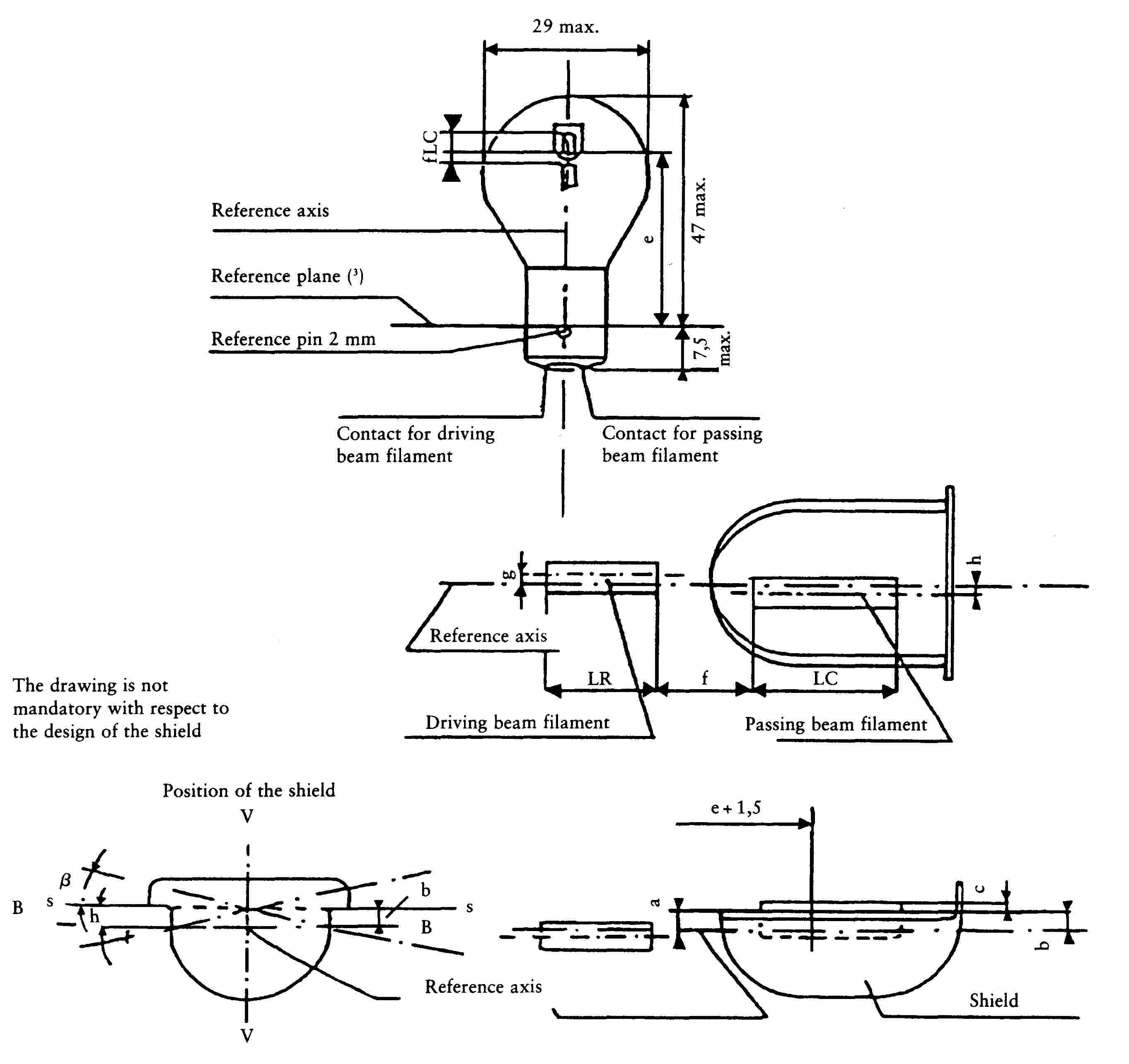
(Dimensions in mm)
Notes
Plane VV contains the reference axis and the centre line of the reference pin.
Plane HH contains the reference axis and is perpendicular to plane VV.
Objective position of plane SS through the shield edges parallel to plane HH.
SHEET S4/2
S4 filament lamp for moped headlamp
|
Dimensions (mm) |
Filament lamps of normal production |
Standard filament lamp |
|||||||
|
min. |
nom. |
max. |
|||||||
|
e |
33,25 |
33,6 |
33,95 |
33,6 ± 0,15 |
|||||
|
f |
1,45 |
1,8 |
2,15 |
1,8 ± 0,2 |
|||||
|
lC, lR |
2,5 |
3,5 |
4,5 |
3,5 ± 0,5 |
|||||
|
c (2) |
0,05 |
0,4 |
0,75 |
0,4 ± 0,15 |
|||||
|
b (2) |
- 0,15 |
0,2 |
0,55 |
0,2 ± 0,15 |
|||||
|
a (2) |
0,25 |
0,6 |
0,95 |
0,6 ± 0,15 |
|||||
|
h |
- 0,5 |
0 |
0,5 |
0 ± 0,2 |
|||||
|
g |
- 0,5 |
0 |
0,5 |
0 ± 0,2 |
|||||
|
β (2) (5) |
- 2o 30′ |
0 |
2o 30′ |
0 ± 1o |
|||||
|
BAX 15d (1) |
|||||||||
|
ELECTRICAL AND PHOTOMETRIC CHARACTERISTICS |
|||||||||
|
Rated voltage |
Volts |
6 |
12 |
6 |
|||||
|
Rated wattage (6) |
Watts |
15 |
15 |
15 |
15 |
15 |
15 |
||
|
Test voltage |
Volts |
6,75 |
13,5 |
||||||
|
Objective wattage (6) |
Watts |
15 |
15 |
15 |
15 |
15 |
15 |
||
|
(at 6,75 V) |
|||||||||
|
Tolerance |
± % |
6 |
6 |
6 |
|||||
|
Objective values |
lum. flux lm (4) (6) |
180 |
125 |
190 |
180 |
125 |
190 |
||
|
min. |
min. |
max. |
min. |
min. |
max. |
||||
|
Reference luminous flux: 240 lm (driving beam), 160 lm (passing beam) at approx. 6 V (4) |
|||||||||
SHEET S4/3
Notes
(1) Cap in accordance with IEC Publication 61 in preparation.
(2) Dimensions a, b, c and β refer to a plane parallel to the reference plane and cutting the two edges of the shield at a distance of e + 1,5 mm.
(3) The reference plane is perpendicular to the reference axis and touches the upper surface of the pin having a length of 2 mm.
(4) The colour of the light emitted must be white.
(5) Admissible deviation of the plane through the shield edges from the objective position.
(6) Values in the left-hand column refer to the driving beam filament, values in the right-hand column refer to the passing beam filament.
Appendix 14
Category P21W
SHEET P21W/1

|
Dimensions in mm |
Filament lamps of normal production |
Standard filament lamp |
|||
|
min. |
nom. |
max. |
|||
|
e |
31,8 (1) |
31,8± 0,3 |
|||
|
f |
12 V |
5,5 |
6,0 |
7,0 |
6,0 ± 0,5 |
|
6,24 V (4) |
7,0 |
||||
|
β |
75o |
90o |
105o |
90o ± 5o |
|
|
Lateral deviation (1) |
0,3 max. |
||||
|
Cap BA 15s in accordance with IEC Publication 61 (sheet 7004-11A-7) (2) |
|||||
|
ELECTRICAL AND PHOTOMETRIC CHARACTERISTICS |
|||||
|
Rated values |
Volts |
6 |
12 |
24 |
12 |
|
Watts |
21 |
21 |
|||
|
Test voltage |
Volts |
6,75 |
13,5 |
28,0 |
|
|
Objective values |
Watts |
26 |
25 |
28 |
25 at 13,5 V |
|
± % |
6 |
6 |
|||
|
Luminous flux lm |
460 |
||||
|
± % |
15 |
||||
|
Reference luminous flux: 460 lm at approximately 13,5 V |
|||||
|
(1) Maximum lateral deviation of filament centre from two reciprocally perpendicular planes both containing the reference axis of cap and one containing axis of pins. (2) Lamps with cap BA 15d may be used for special purposes: they have the same dimensions. (3) To be checked by means of a ‘box-system’, sheet P21W/2. (4) For 24 volt heavy-duty lamps having a different filament shape, additional specifications are under consideration. |
|||||
The colour of the light must be white.
SHEET P21W/2
Screen projection requirements
This test is used to determine, by checking whether the filament is correctly positioned relative to the reference axis and the reference plane and has an axis perpendicular, within ± 15o, to the plane through the centres of the pins and the reference axis, whether a filament lamp complies with the requirements.
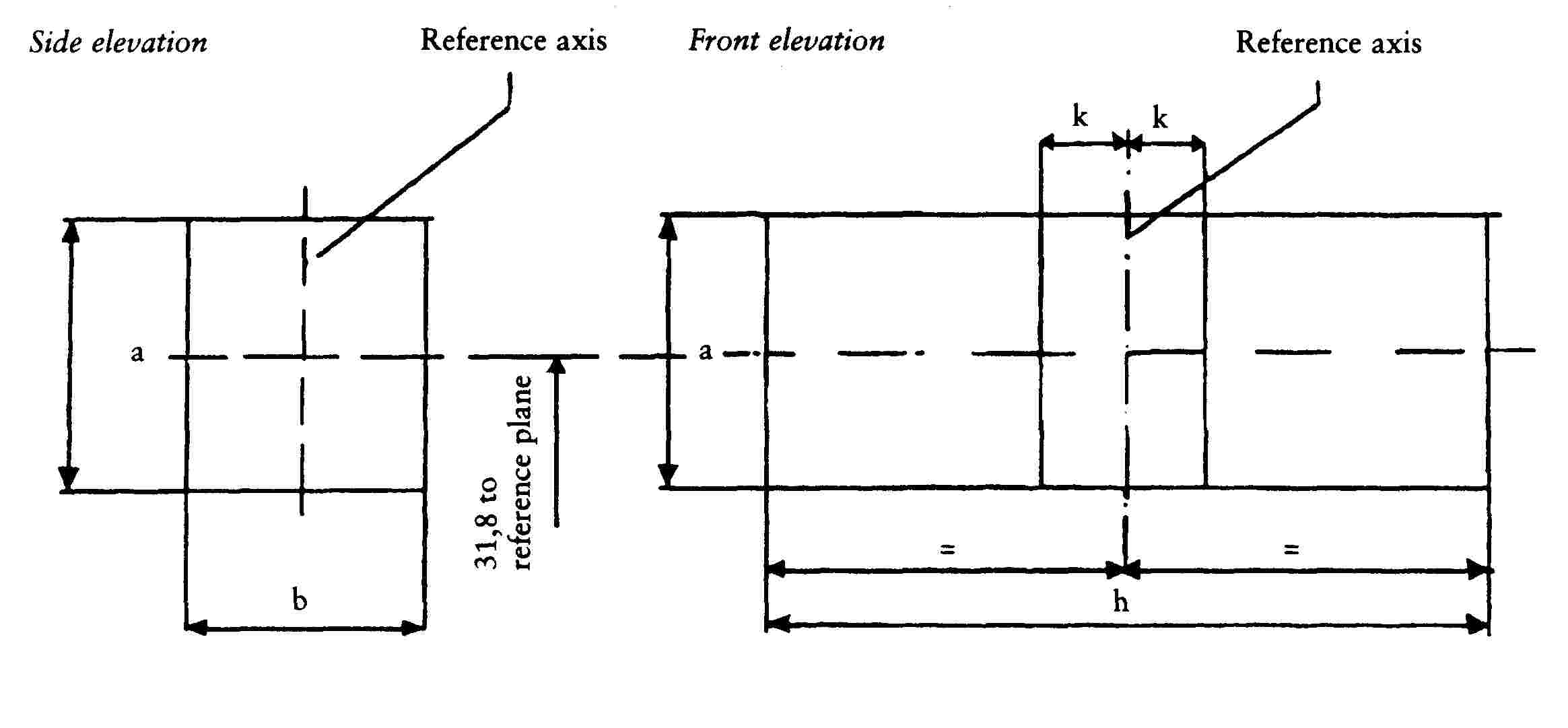
(Dimensions in millimetres)
|
reference |
a |
b |
h |
k |
|
dimension |
3,5 |
3,0 |
9,0 |
1,0 |
Test procedure and requirements
|
1. |
The lamp is placed in a holder (socket) capable of being rotated about its axis and having either a calibrated scale or fixed stops corresponding to the angular-displacement tolerance limits, i.e. ± 15o. The holder is then so rotated that an end view of the filament is seen on the screen on to which the image of the filament is projected. The end view of the filament is obtained within the angular-displacement tolerance limits (± 15o). |
|
2. |
Side elevation The lamp being placed with the cap down, the reference axis vertical, and the filament seen end-on, the projection of the filament must lie entirely within a rectangle of height ‘a’ and width ‘b’ having its centre at the theoretical position of the centre of the filament. |
|
3. |
Front elevation The lamp being placed with the cap down and the reference axis vertical, the lamp being viewed in a direction at right-angles to the filament axis:
|
Appendix 15
Category P21/5W
SHEET P21/5W/1

|
Dimensions in mm |
Filament lamps of normal production |
Standard filament lamp |
||||||
|
min. |
nom. |
max. |
||||||
|
e |
31,8 (1) |
31,8 ± 0,3 |
||||||
|
f |
7,0 (1) |
7,0 - 0 - 2 |
||||||
|
Lateral deviation |
0,3 max. (2) |
|||||||
|
x, y |
2,8 ± 0,3 |
|||||||
|
β |
75o (1) |
90o |
105o (1) |
90o ± 5o |
||||
|
Cap BAY 15d in accordance with IEC Publication 61 (sheet 7004-11B-5) |
||||||||
|
ELECTRICAL AND PHOTOMETRIC CHARACTERISTICS |
||||||||
|
Rated values |
Volts |
6 |
12 |
24 (3) |
12 |
|||
|
Watts |
21 |
5 |
21 |
5 |
21 |
5 |
21/5 |
|
|
Test voltage |
Volts |
6,75 |
13,5 |
28,0 |
||||
|
Objective values |
Watts |
26 |
6 |
25 |
6 |
28 |
10 |
25 and 6 at 13,5 V |
|
± % |
6 |
10 |
6 |
10 |
6 |
10 |
6 and 10 |
|
|
Luminous flux lm |
440 |
35 |
440 |
35 |
440 |
40 |
||
|
± % |
15 |
20 |
15 |
20 |
15 |
20 |
||
|
Reference luminous flux: 440 lm and 35 lm at approx. 13,5 V |
||||||||
|
(1) These dimensions should be checked by means of a ‘box-system’ (P21/5W/2, P21/5W/3) based on the dimensions and tolerances shown above. ‘x’ and ‘y’ refer to the main (high-wattage) filament, not to the lamp axis (P21/5W/2). Means of increasing the positioning accuracy of the filament and of the cap-holder assembly are under consideration. (2) Maximum lateral deviation of main (high-wattage) filament centre from two mutually perpendicular planes both containing reference axis and one containing axis of pins. (3) The 24 volt filament lamp is not recommended for future embodiments. |
||||||||
The colour of the light emitted must be white.
SHEET P21/5W/2
Screen projection requirements
This test is used to determine, by checking
a) whether the main (high-wattage) filament is correctly positioned relative to the reference axis and the reference plane and has an axis perpendicular, within ± 15o, to the plane through the centres of the pins and the reference axis; and
b) whether the auxiliary (low-wattage) filament is correctly positioned relative to the main (high-wattage) filament
whether a filament lamp complies with the requirements.
Test procedure and requirements
|
1. |
The lamp is placed in a holder (socket) capable of being rotated about its axis and having either a calibrated scale or fixed stops corresponding to the angular-displacement tolerance limits, i.e. ± 15o. The holder is then so rotated that an end view of the main (high-wattage) filament is seen on the screen onto which the image of the filament is projected. The end view of the main (high-wattage) filament is obtained within the angular-displacement tolerance limits (± 15o). |
|
2. |
Side elevation The lamp being placed with the cap down, the reference axis vertical, and the main (high-wattage) filament seen end-on:
|
|
3. |
Front elevation The lamp being placed with the cap down and the reference axis vertical, the lamp being viewed in a direction at right-angles to the axis of the main (high-wattage) filament:
|
SHEET P21/5W/3
Side elevation

(Dimensions in millimetres)
|
Reference |
a |
b |
c |
d |
u |
v |
|
Dimensions |
3,5 |
3,0 |
4,8 |
2,8 |
||
Front elevation

|
Reference |
a |
h |
k |
|
Dimensions |
3,5 |
9,0 |
1,0 |
Appendix 16
Category R5W
SHEET R5W/1

|
Reference plane |
Filament lamps of normal production |
Standard filament lamp |
|||
|
min. |
nom. |
max. |
|||
|
e |
17,5 |
19,0 |
20,5 |
19,0 ± 0,3 |
|
|
Lateral deviation (2) |
1,5 |
0,3 max. |
|||
|
β |
60o |
90o |
120o |
90o ± 5o |
|
|
Cap BA 15s in accordance with IEC Publication 61 (sheet 7004-11A-6) (1) |
|||||
|
ELECTRICAL AND PHOTOMETRIC CHARACTERISTICS |
|||||
|
Rated values |
Volts |
6 |
12 |
24 (3) |
12 |
|
Watts |
5 |
5 |
|||
|
Test voltage |
Volts |
6,75 |
13,5 |
28,0 |
|
|
Objective values |
Watts |
5 |
7 |
5 at 13,5 V |
|
|
± % |
10 |
10 |
|||
|
Luminous flux lm |
50 |
||||
|
± % |
20 |
||||
|
Reference luminous flux: 50 lm at approx. 13,5 V |
|||||
The colour of the light emitted must be white.
(1) Filament lamps with cap BA 15d may be used for special purposes: they have the same dimensions.
(2) Maximum lateral deviation of filament centre from two reciprocally perpendicular planes both containing reference axis and one containing axis of pins.
(3) For 24 volt heavy-duty lamps having a different filament shape, additional specifications are under consideration.
(4) See Appendix 24.
Appendix 17
Category R10W
SHEET R10W/1

|
Dimensions in mm |
Filament lamp of normal production |
Standard filament lamp |
|||
|
min. |
nom. |
max. |
|||
|
e |
17,5 |
19,0 |
20,5 |
19,0 ± 0,3 |
|
|
Lateral deviation (2) |
1,5 |
0,3 max. |
|||
|
β |
60o |
90o |
120o |
90o ± 5o |
|
|
Cap BA 15s in accordance with IEC Publication 61 (sheet 7004-11A-6) (1) |
|||||
|
ELECTRICAL AND PHOTOMETRIC CHARACTERISTICS |
|||||
|
Rated values |
Volts |
6 |
12 |
24 (3) |
12 |
|
Watts |
10 |
10 |
|||
|
Test voltage |
Volts |
6,75 |
13,5 |
28,0 |
|
|
Objective values |
Watts |
10 |
12,5 |
10 at 13,5 V |
|
|
± % |
10 |
10 |
|||
|
Luminous flux lm |
125 |
||||
|
± % |
20 |
||||
|
Reference luminous flux: 125 lm at approx. 13,5 V |
|||||
The colour of the light emitted must be white.
(1) Filament lamps with cap BA 15d may be used for special purposes: they have the same dimensions.
(2) Maximum lateral deviation of filament centre from two reciprocally perpendicular planes both containing reference axis and one containing axis of pins.
(3) For 24 volt heavy-duty filament lamps having a different filament shape, additional specifications are under consideration.
(4) See Appendix 24.
Appendix 18
Category T4W
SHEET T4W/1

|
Dimensions in mm |
Filament lamps of normal production |
Standard filament lamp |
|||
|
min. |
nom. |
max. |
|||
|
e |
13,5 |
15,0 |
16,5 |
15,0 ± 0,3 |
|
|
lateral deviation (1) |
1,5 |
0,5 max. |
|||
|
β |
90o |
90o ± 5o |
|||
|
Cap BA 9s in accordance with IEC Publication 61 (sheet 7004-14-6) (3) |
|||||
|
ELECTRICAL AND PHOTOMETRIC CHARACTERISTICS |
|||||
|
Rated values |
Volts |
6 |
12 |
24 |
12 |
|
Watts |
4 |
4 |
|||
|
Test voltage |
Volts |
6,75 |
13,5 |
28,0 |
|
|
Objective values |
Watts |
4 |
5 |
4 at 13,5 V |
|
|
± % |
10 |
10 |
|||
|
Luminous flux lm |
35 |
||||
|
± % |
20 |
||||
|
Reference luminous flux: 35 lm at approx. 13,5 V |
|||||
(1) Maximum lateral deviation of filament centre from two reciprocally perpendicular planes both containing reference axis and one containing axis of pins.
(2) See Appendix 24.
(3) Over the entire length of the cap there must be no projections or soldering extending beyond the permissible maximum diameter of the cap.
Appendix 19
Category C5W
SHEET C5W/1
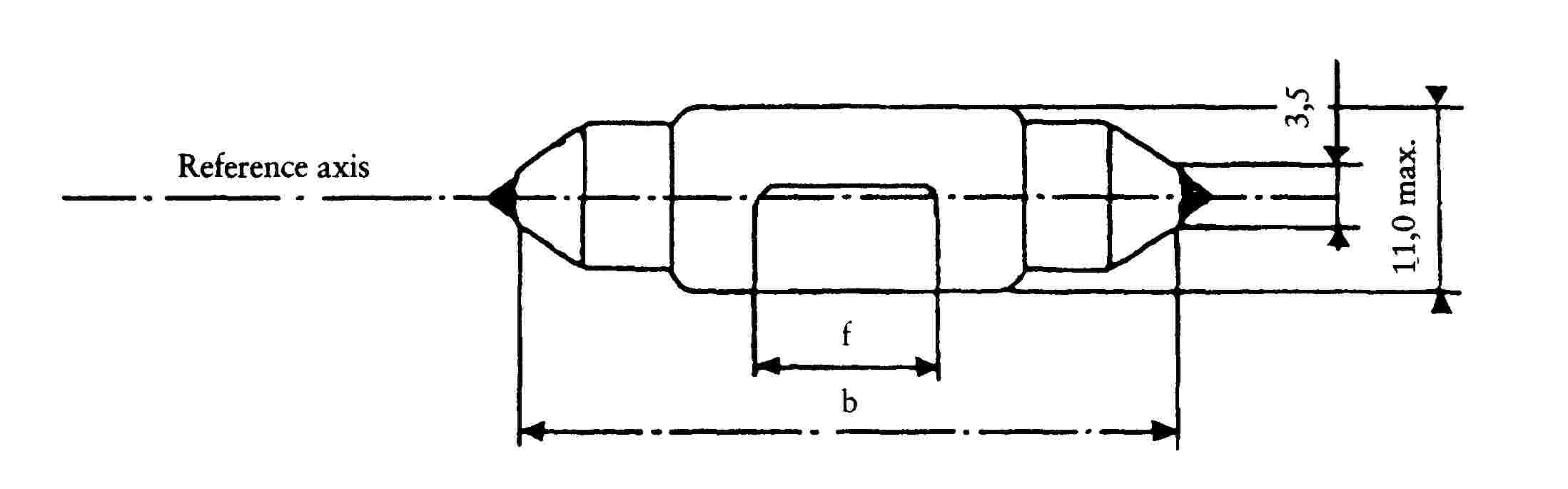
|
Dimensions in mm |
Filament lamps of normal production |
Standard filament lamp |
|||
|
min. |
nom. |
max. |
|||
|
b (1) |
34,0 |
35,0 |
36,0 |
35 ± 0,5 |
|
|
7,5 (4) |
15 (5) |
9 ± 1,5 |
|||
|
Cap SV 8,5 in accordance with IEC Publication 61 (sheet 7004-81-3) |
|||||
|
ELECTRICAL AND PHOTOMETRIC CHARACTERISTICS |
|||||
|
Rated values |
Volts |
6 |
12 |
24 |
12 |
|
Watts |
5 |
5 |
|||
|
Test voltage |
Volts |
6,75 |
13,5 |
28,0 |
|
|
Objective values |
Watts |
5 |
7 |
5 at 13,5 V |
|
|
± % |
10 |
10 |
|||
|
Luminous flux lm |
45 |
||||
|
± % |
20 |
||||
|
Reference luminous flux: 45 lm at approx. 13,5 V |
|||||
|
(1) This dimension corresponds to the distance between two apertures of 3,5 mm diameter each bearing against one of the caps. (2) The filament must be housed in a cylinder 19 mm long co-axial with the filament lamp axis and placed symmetrically about the lamp centre. The diameter of this cylinder is for 6 volt and 12 volt filament lamps: d + 4 mm (for standard filament lamps: d + 2 mm) and for 24 volt filament lamps: d + 5 mm, ‘d’ being the nominal diameter of the filament as stated by the manufacturer. (3) The deviation of the filament centre from the centre of the lamp's length should not be more than ± 2 mm (for standard filament lamps: ± 0,5 mm) measured in the direction of the reference axis. (4) 4,5 mm for 6 volt filament lamps. (5) 16,5 mm for 24 volt filament lamps. |
|||||
The colour of the light emitted must be white.
Appendix 20
Category C21W
SHEET C21W/1
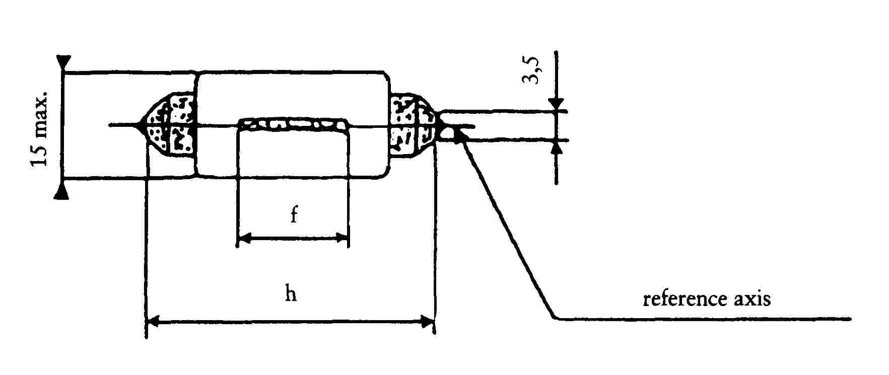
|
Dimensions in mm |
Filament lamps of normal production |
Standard filament lamp |
|||
|
min. |
nom. |
max. |
|||
|
b (1) |
40,0 |
41,0 |
42,0 |
41 ± 0,5 |
|
|
f (2) |
7,5 |
10,5 |
8 ± 1 |
||
|
Cap SV 8,5 in accordance with IEC Publication 61 (sheet 7004-81-3) |
|||||
|
ELECTRICAL AND PHOTOMETRIC CHARACTERISTICS |
|||||
|
Rated values |
Volts |
12 |
12 |
||
|
Watts |
21 |
21 |
|||
|
Test voltage |
Volts |
13,5 |
|||
|
Objective values |
Watts |
25 |
25 at 13,5 V |
||
|
± % |
6 |
6 |
|||
|
Luminous flux lm |
460 |
||||
|
± % |
15 |
||||
|
Reference luminous flux: 460 lm at approx. 13,5 V |
|||||
|
(1) This dimension corresponds to the distance between two apertures of 3,5 mm diameter. (2) The position of the filament is checked by means of a ‘box-system’, sheet C21W/2. |
|||||
The colour of the light emitted must be white.
SHEET C21W/2
Screen projection requirements
This test is used to determine whether a filament lamp complies with the requirements, by checking whether the filament is correctly positioned relative to the reference axis and to the centre of the lamp's lenght.

(Dimensions in millimetres)
|
a |
h |
k |
|
|
12 V |
4,0 + d |
14,5 |
2,0 |
d = nominal diameter of filament as stated by the manufacturer.
For standard filament lamp: a = 2,0 + d k = 0,5
Test procedure and requirements
|
1. |
The lamp is placed in a holder (socket) capable of being so rotated through 360o about the reference axis that the front elevation is seen on the screen on to which the image of the filament is projected. The reference plane on the screen must coincide with the centre of the lamp. The central axis sought on the screen must coincide with the centre of the lamp's length. |
|
2. |
Front elevation
|
Appendix 21
Category W3W
SHEET W3W/1
|
Dimensions in mm |
Filament lamps of normal production |
Standard filament lamp |
|||
|
min. |
nom. |
max. |
|||
|
e |
11,2 |
12,7 |
14,2 |
12,7 ± 0,3 |
|
|
Lateral deviation (2) |
1,5 |
0,5 max. |
|||
|
β |
- 15o |
0o |
+ 15o |
0o ± 5o |
|
|
Cap W 2,1 × 9,5d in accordance with IEC Publication 61 (sheet 7004-91-2) (1) |
|||||
|
ELECTRICAL AND PHOTOMETRIC CHARACTERISTICS |
|||||
|
Rated values |
Volts |
6 |
12 |
24 |
12 |
|
Watts |
3 |
3 |
|||
|
Test voltage |
Volts |
6,75 |
13,5 |
28,0 |
|
|
Objective values |
Watts |
3 |
4 |
3 at 13,5 V |
|
|
± % |
15 |
15 |
|||
|
Luminous flux lm |
22 |
||||
|
± % |
30 |
||||
|
Reference luminous flux: 22 lm at approx. 13,5 V |
|||||
The colour of the light emitted must be white.
(1) This type is protected by patents; ISO/IEC conditions apply.
(2) Maximum lateral deviation of filament centre from two reciprocally perpendicular planes both containing reference axis and one containing axis X-X.
(3) See Appendix 24.
Appendix 22
Category W5W
SHEET W5W/1
|
Dimensions in mm |
Filament lamps of normal production |
Standard filament lamp |
|||
|
min. |
nom. |
max. |
|||
|
e |
11,2 |
12,7 |
14,2 |
12,7± 0,3 |
|
|
Lateral deviation (2) |
1,5 |
0,5 max. |
|||
|
β |
- 15o |
0o |
+ 15o |
0o ± 5o |
|
|
Cap W 2,1 × 9,5d in accordance with IEC Publication 61 (sheet 7004-91-2) (1) |
|||||
|
ELECTRICAL AND PHOTOMETRIC CHARACTERISTICS |
|||||
|
Rated values |
Volts |
6 |
12 |
24 |
12 |
|
Watts |
5 |
5 |
|||
|
Test voltage |
Volts |
6,75 |
13,5 |
28,0 |
|
|
Objective values |
Watts |
5 |
7 |
5 at 13,5 V |
|
|
± % |
10 |
10 |
|||
|
Luminous flux lm |
50 |
||||
|
± % |
20 |
||||
|
Reference luminous flux: 50 lm at approx. 13,5 V |
|||||
The colour of the light emitted must be white.
(1) This type is protected by patents; ISO/IEC conditions apply.
(2) Maximum lateral deviation of filament centre from two reciprocally perpendicular planes both containing reference axis and one containing axis XX.
(3) (See Appendix 24.
Appendix 23
Example of the arrangement of the approval mark
The above EC component type-approval mark affixed to a filament lamp indicates that the lamp has been approved in Germany (e1) under the approval number A3. The first character of the approval code (0) indicates that the approval was granted in accordance with the requirements of Annex IV to this Directive in its original form.
Appendix 24
Luminous centre and shapes of lamp filaments
Save as possibly otherwise indicated on the lamp data sheets, this standard is applicable to the determination of the luminous centre of different filament shapes if the filament is shown as a point in at least one view in the lamp data sheets.
The position of the luminous centre depends upon the filament shape.
|
No |
Filament shapes |
Observations |
|
1 |
|
With b > 1,5 h, the deviation of the filament axis with respect to a plane normal to the reference axis must not exceed 15o. |
|
2 |
|
Only applicable to filaments which can be inscribed in a rectangle of b > 3 h. |
|
3 |
|
Applicable to filaments which can be inscribed in a rectangle of b < 3 h, where however k < 2 h. |


The side lines of the circumscribed rectangle in Nos 2 and 3 are parallel and perpendicular, respectively, to the reference axis.
The luminous centre is the point of intersection of the dash-dot lines.
CHAPTER 3
EXTERNAL PROJECTIONS FROM TWO OR THREE-WHEEL MOTOR VEHICLES
LIST OF ANNEXES
|
ANNEX I |
Requirements applying to external projections from two-wheel motor vehicles |
|
Appendix |
Testing device and text conditions |
|
ANNEX II |
Requirements applying to external projections from two-wheel motor vehicles |
|
Appendix |
Measurement of projections and gaps |
|
ANNEX III |
|
|
Appendix 1 |
Information document in respect of external projections from a type of two or three-wheel motor vehicle |
|
Appendix 2 |
Certificate of component type approval in respect of external projections from a type of two or three-wheel vehicle |
ANNEX I
REQUIREMENTS APPLYING TO EXTERNAL PROJECTIONS FROM TWO-WHEEL MOTOR VEHICLES
1. DEFINITIONS
For the purposes of this Annex:
|
1.1. |
‘outer parts of the vehicle’: means the parts of the vehicle likely to be involved with external obstacles in the event of a collision; |
|
1.2. |
‘grazing’: means any contact which, under certain conditions, could cause injury by laceration; |
|
1.3. |
‘collision’: means any contact which, under certain conditions could cause penetration injuries; |
|
1.4. |
‘type of vehicle in respect of external projections’: means vehicles not differing essentially from one another with regard, in particular, to the shape, dimensions, direction of travel and hardness of the outer parts of the vehicle; |
|
1.5. |
‘radius of curvature’: means radius ‘r’ of the arc of the circle most closely approaching the rounded shape of the part under consideration. |
2. CRITERIA FOR DISTINGUISHING BETWEEN ‘GRAZING’ AND ‘COLLISION’
|
2.1. |
When the testing device (shown in Figure A in the Appendix) is moved along the vehicle as described in item 4.2 below, the parts of the vehicle touched by that device must be considered to fall within:
|

3. GENERAL REQUIREMENTS
|
3.1. |
Notwithstanding the requirements of item 3.2, the outside of all types of vehicle shall incorporate no pointed, sharp or protruding parts, pointing outwards, of such a shape, dimension, angle of direction or hardness that it increases the risk or seriousness of body lesions suffered by any person struck or grazed by the vehicle in the event of an accident. |
|
3.2. |
Vehicles shall be designed in such a way that the parts with which other road users are likely to come into contact comply with items 5 and 6, as appropriate. |
|
3.3. |
All external projections covered by this Annex which are made of or covered with soft rubber or plastic having a hardness of less than 60 Shore A are considered to meet the requirements set out in items 5 and 6. |
|
3.4. |
However, the following specifications shall not apply to the space between the side-car and motorcycle in motorcycle combinations. |
|
3.5. |
Where mopeds are fitted with pedals, compliance with all of the requirements or parts of these laid down by this Directive in respect of the pedals is optional. Where the requirements are not met, manufacturers' shall inform the authorities receiving the request for the component type-approval of external projections from a type of vehicle and shall at the same time describe the measures taken in order to ensure safety. |
|
3.6. |
In the case of two-wheel vehicles that are fitted with a form of structure or panels intended to enclose, or partially enclose, the driver or passengers or to cover components of the vehicle, the type-approval authority or technical service may, at its discretion and in discussion with the vehicle manufacturer, apply the requirements of this Annex, or of Annex II, to all or part of the vehicle based on an assessment of the worst case condition. |
4. TEST METHODS
4.1. Testing device and test conditions
|
4.1.1. |
The testing device shall be as described in the Appendix, Fig. A. |
|
4.1.2. |
The test vehicle shall be held in a straight line and a vertical position with both wheels touching the ground. The steering device shall be free to move within its normal range. An AM 50 percentile anthropomorphic dummy or a person of similar physical characteristics shall be placed on the test vehicle in the normal driving position in such a way that it does not hamper the free movement of the steering device. |
4.2. Test procedure
The test device shall be moved from the front towards the rear of the test vehicle and (if it is able to strike the testing device) the steering control shall be rotated into its fully locked position. The test device must remain in contact with the vehicle (see Figure B in the Appendix). The test shall be carried out on both sides of the vehicle.
5. CRITERIA
|
5.1. |
The criteria set out in this item shall not apply to the parts covered by the requirements of item 6 below. |
|
5.2. |
Apart from the exemption set out in item 3.3 above, the following minimum criteria shall apply:
|
6. SPECIFIC REQUIREMENTS
|
6.1. |
The upper edge of the windscreen of fairing shall have a radius of curvature of at least 2 mm or else be covered with an edge-protection material in accordance with item 3.3. |
|
6.2. |
The end of the clutch and brake levers shall be perceptibly spherical and have a radius of curvature of at least 7 mm. The outer edges of these levers shall have a radius of curvature of not less than 2 mm. The verification is done with the levers in non-applied position. |
|
6.3. |
The leading edge of the front mudguard shall have a radius of curvature of at least 2 mm. |
|
6.4. |
The rear edge of any filler cap located on the upper surface of the fuel tank and thus likely to be struck by the rider in a collision shall not extend more than 15 mm above the underlying surface; any connection with the underlying surface shall be smooth or perceptibly spherical. If the 15 mm requirement cannot be met other measures — such as a protective device located behind the filler neck — must be provided (see, for example, the following sketch).
|
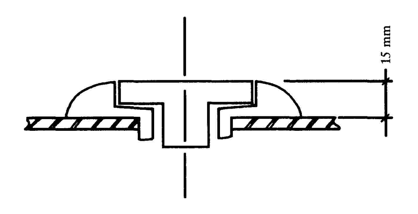
|
6.5. |
The ignition keys shall have protective cap. This requirement does not apply to folding keys or keys which are flush with the surface. |
Appendix 1
Testing device and test conditions
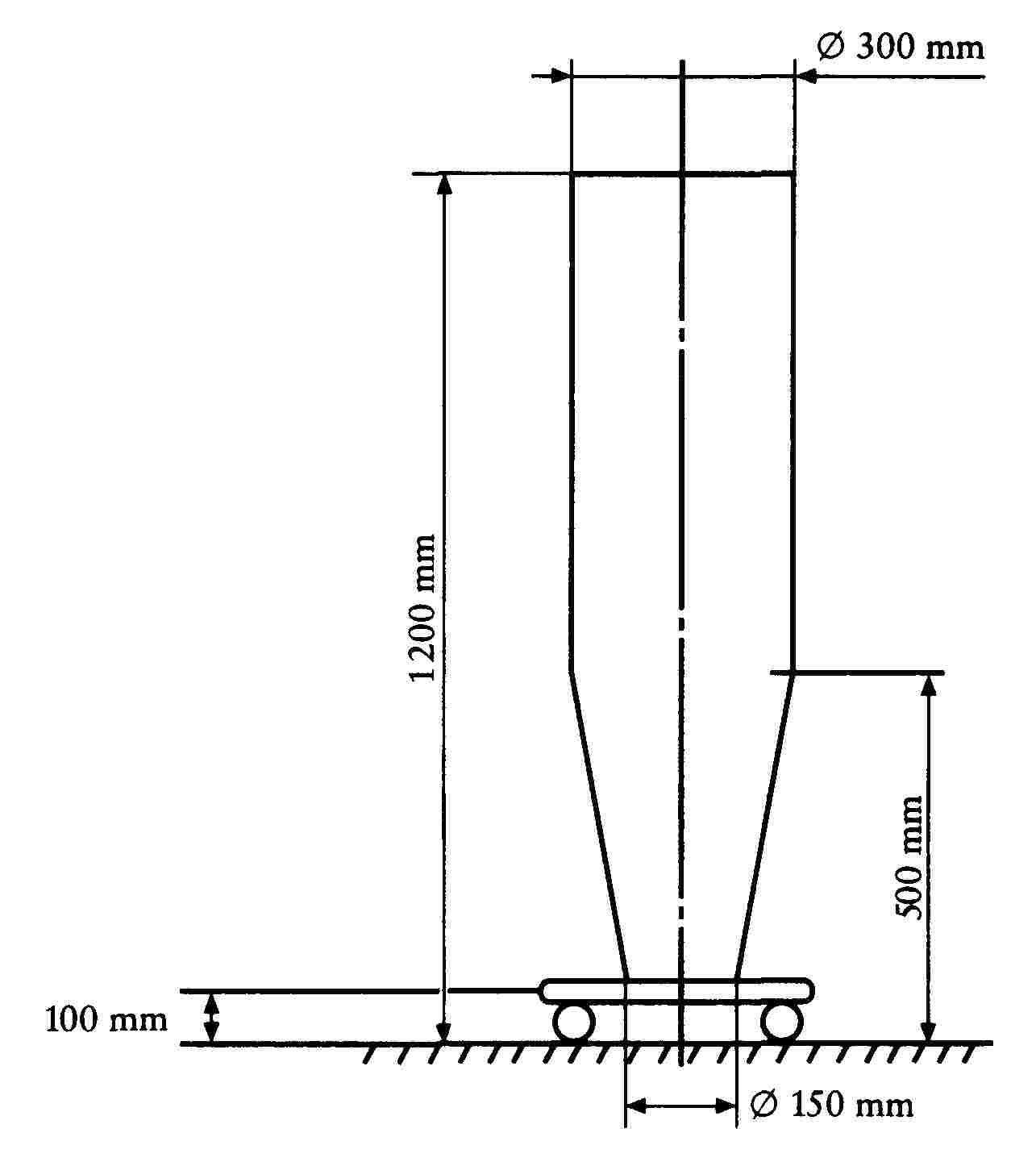
Figure A

Figure B
ANNEX II
REQUIREMENTS APPLYING TO EXTERNAL PROJECTIONS FROM THREE-WHEEL MOTOR VEHICLES, LIGHT QUADRICYCLES AND QUADRICYCLES
GENERAL
The requirements set out in Directive 74/483/EEC ( 59 ) relating to the external projections of (category M1) motor vehicles shall apply to three-wheel motor vehicles intended for the carriage of passengers.
However, bearing in mind the variety of forms of construction of these vehicles, the type approval authority or technical service may, at its discretion and in discussion with the vehicle manufacturer, apply the requirements of this Annex, or of Annex I to all or part of the vehicle, based on an assessment of the worst case condition.
This shall also apply to the requirements given below with regard to the requirements for three-wheel vehicles, light quadricycles and quadricycles.
The following requirements shall apply to three-wheel motor vehicles, light quadricycles and quadricycles intended for the carriage of goods.
1. SCOPE
|
1.1. |
This Annex shall apply to external projections ahead of the rear bulkhead of the cab on vehicles intended for the carriage of goods, those external projections being restricted to the outer surface as defined below. It does not apply to outside rear view mirrors, including their stem, or to accessories such as radio aerials and luggage carriers. |
|
1.2. |
The aim is to reduce the risk or seriousness of injuries sustained by any person coming into contact with the outer surface of the vehicle in the event of a collision. |
2. DEFINITIONS
For the purpose of this Annex:
|
2.1. |
‘outer surface’ means the part of the vehicle ahead of the rear bulkhead of the cab as defined in 2.4 below, with the exception of the rear bulkhead itself, but including components such as any front wing(s) and front bumper and the front wheel(s) (if fitted); |
|
2.2. |
‘type of vehicle in respect of external projections’ means vehicles not differing essentially from one another with regard, in particular, to the shape, dimensions, direction of travel and hardness of the outer parts of the vehicle; |
|
2.3. |
‘cab’ means that part of the bodywork constituting the compartment reserved for the driver and passenger, including its doors; |
|
2.4. |
‘rear cab bulkhead’ means the part situated furthermost to the rear of the outer surface of the compartment reserved for the driver and passenger; |
|
2.5. |
‘reference plane’ a horizontal plane passing through the centre of the front wheel(s), or a horizontal plane located 50 cm above the ground, the lower of the two being selected. This plane is defined for a laden vehicle; |
|
2.6. |
‘floor line’ means a line determined as follows: a vertical-axis cone of an indeterminate height having a half-angle of 15 % is moved all around the outside structure of the vehicle in such a way that it remains tangent, as low as possible, to the outer surface of the bodywork. The floor line is the geometrical trace of the tangency points. When the floor line is determined, account shall not be taken of the exhaust pipes, wheels or localized operational mechanical components attached to the floor pan, such as jacking points, suspension mountings, attachment points for towing or transport purposes. It is assumed that any gaps directly above the wheel arches are filled by an imaginary surface directly prolonging the adjacent outside surface. In order to determine the floor line, depending upon the type of vehicle under consideration, account shall be taken of the extremity of the profile of the body panel, of any wing or wings (if fitted) and of any outside angle of the bumper section (if fitted). If there are simultaneously two or several tangency points, it is the lower or the lowest tangency point which determines the floor line; |
|
2.7. |
‘radius of curvature’ means the radius of the arc of a circle closest to the rounded shape of the part under consideration; |
|
2.8. |
‘laden vehicle’ means the vehicle bearing its maximum technically permissible load, that load being distributed among the axles in accordance with the manufactuer's instructions. |
3. GENERAL REQUIREMENTS
|
3.1. |
The provisions of this Annex shall not apply to the parts of the ‘outer surface’ of the vehicle which, when the vehicle is unladen and the doors, windows and hatches providing access to the cab etc. are in their closed position, are located:
|
|
3.2. |
The ‘external surface’ of the vehicle shall not include any part, pointing towards the outside, which could catch against pedestrians, cyclists or motor cyclists. |
|
3.3. |
None of the components defined in item 4 below may incorporate any pointed or sharp component facing towards the outside, or any projection, shape, dimensions, direction or hardness of which would be likely to increase the risk or seriousness of corporal lesions to a person hit or grazed by the external surface in the event of a collision. |
|
3.4. |
Projections from the external surface having a hardness of not more than 60 Shore (A) may have a radius of curvature less than the values laid down in item 4 below. |
|
3.5. |
If, by way of a departure from the requirements of item 4, the radius of curvature of any outer projection is less than 2,5 mm, it shall be covered by a form of protection having the characteristics stated in 3.4. |
4. SPECIFIC REQUIREMENTS
4.1. Ornamental motifs, trade symbols, commercial-logo letters and digits
|
4.1.1. |
Ornamental motifs, trade symbols, trade-logo letters and digits shall not include any radius of curvature of less than 2,5 mm. This requirement shall not apply to components projecting by less than 5 mm from the adjacent surface, provided that they do not have any cutting edges pointing to the outside. |
|
4.1.2. |
Ornamental motifs, trade symbols, trade-logo letters and digits projecting by more than 10 mm from the surrounding surface shall retract, detach or fold back under a force of 10 daN exerted on their most projecting point in any direction within a plane roughly parallel to the surface to which they relate. The force of 10 daN shall be exerted by means of a flat-tipped punch having a maximum diameter of 50 mm. Failing this, an equivalent method shall be used. Once any ornamental motifs have been retracted, detached or folded back the remaining parts shall not project by more than 10 mm or incorporate any pointed, sharp or cutting edges. |
4.2. Headlamp peaks and surrounds
|
4.2.1. |
Projecting peaks and surrounds shall be permitted on headlamps provided that they do not project by more than 30 mm from the outer transparent surface of the headlamp and that their radius of curvature is at no point less than 2,5 mm. |
|
4.2.2. |
Pop-up headlamps shall meet the requirements set out in item 4.2.1 above in both their operating and concealed position. |
|
4.2.3. |
The provisions of item 4.2.1 above shall not apply to headlamps which are embedded or recessed in the bodywork if this complies with item 3.2 above. |
4.3. Grills
Grill components shall have radii of curvature of
— at least 2,5 mm if the distance between consecutive components exceeds 40 mm
— at least 1 mm if that distance lies between 25 mm and 40 mm
— at least 0,5 mm if that distance is less than 25 mm.
4.4. Windscreen and headlamp wash/wipe system
|
4.4.1. |
The abovementioned devices shall be mounted in such a way that the wiper-blade spindle is covered with a protector having a radius of curvature of at least 2,5 mm and a minimum area of 150 mm2 measured in the form of a projection over a section which is at the most 6,5 mm from the most projecting point. |
|
4.4.2. |
The windscreen and headlamp-washer nozzles shall have a radius of curvature of at least 2,5 mm. If they project by less than 5 mm their sharp edges pointing to the outside shall be smooth polished. |
4.5. Wing (if fitted)
If the wing is the part of the vehicle located furthest ahead of the cab, its constituent parts shall be designed in such a way that all of the rigid parts facing the outside have a radius of curvature of at least 5 mm.
4.6. Protective devices (bumpers) (if fitted)
|
4.6.1. |
The extremities of the front protective devices shall be turned down towards the external surface of the bodywork |
|
4.6.2. |
The components of the front protective devices shall be designed in such a way that all of the rigid surfaces pointing to the outside cover a radius of curvature of at least 5 mm. |
|
4.6.3. |
Accessories such as tow hooks and winches shall not project beyond the foremost surface of the bumpers. However, winches may project beyond the foremost surface of the bumpers provided that they are covered, when not in use, by an appropriate protective device having a radius of curvature of at least 2,5 mm. |
|
4.6.4. |
The requirements set out in item 4.6.2 shall not apply to components relating to the bumpers or forming part thereof or to components integral with the bumpers and not projecting by more than 5 mm. The edges of devices protruding by less than 5 mm shall be smooth polished. The specific requirements relating to devices attached to the bumpers and referred to in other items in this Annex shall remain applicable. |
4.7. Handles, hinges and push buttons for doors, bootlids and bonnets, access shutters and flaps and grab handles
|
4.7.1. |
Push buttons shall not protrude by more than 30 mm, grab handles and bonnet-locking grips by more than 70 mm or any other cases by more than 50 mm. Their radius of curvature shall be at least 2,5 mm. |
|
4.7.2. |
If the handles for the side doors are of the rotary type, they shall meet one of the following two conditions:
|
4.8. Side air and rain deflectors and window dirt deflectors
Edges which may point outwards shall have a radius of curvature of at least 1 mm.
4.9. Sheet metal edges
Sheet metal edges shall be permitted provided that they are covered with a protector having a radius of curvature of at least 2,5 mm or with a material meeting the requirements stated in item 3.4.
4.10. Wheel nuts, hubcaps and protective devices
|
4.10.1. |
Wheel nuts, hubcaps and protective devices shall not incorporate any projections in the form of fins. |
|
4.10.2. |
When the vehicle is travelling in a straight line no part of the wheels other than the tyres located above the horizontal plane passing through their axis of rotation shall extend beyond the vertical projection, in a horizontal plane, of the edge of the body panel above the wheel. However, where so justified by operating requirements, the protectors covering the wheel nuts and hubs may extend beyond the vertical projection of that edge provided that the radius of curvature of the surface of the projecting part is at least 5 mm and that, in relation to the vertical projection of the body-panel edge, the projection in no case exceeds 30 mm. |
|
4.10.3. |
Where the nuts and bolts extend outside the plane projection from the outer surface of the tyres (part of the tyres located above the horizontal plane passing through the axis of rotation of the wheel), a protector or protectors complying with item 4.10.2 above shall be fitted. |
4.11. Jacking points and exhaust pipe(s)
|
4.11.1. |
Jacking points and exhaust pipe(s), if any, shall not extend more than 10 mm beyond either the vertical projection of the floor line or the vertical projection of the intersection of the reference plane with the outer surface of the vehicle. |
|
4.11.2. |
By way of departure from this requirement, an exhaust pipe may form a projection of more than 10 mm provided that its extreme sharp ends are rounded off to a minimum radius of curvature of 2,5 mm. |
|
4.12. |
The projections and distances shall be measured in accordance with the requirements referred to in the Appendix. |
Appendix
Measurement of projections and gaps
1. METHOD OF DETERMINING THE EXTENT OF PROJECTION OF A COMPONENT MOUNTED ON THE OUTER SURFACE
|
1.1. |
The extent of projection of a component mounted on a convex panel may be determined either directly or by reference to a sketch of an appropriate section of that component in its fitted position. |
|
1.2. |
If the extent of the projection of a component mounted on a panel other than convex cannot be determined by means of a simple measurement, it must be determined via the maximum variation in the distance between the centre of a 100 mm diameter sphere and the nominal line of the panel when the sphere is moved, while remaining constantly in contact with that component. An example of the use of this method is given in Figure 1. |
|
1.3. |
The extent of projection of, in particular, grab handles shall be measured in relation to a plane passing through the attachment points for those handles. Figure 2 shows an example. |
2. METHOD OF DETERMINING THE EXTENT OF PROJECTION OF HEADLAMP PEAKS AND SURROUNDS
|
2.1. |
The projection beyond the outer surface of the headlamp shall be measured horizontally from the point of tangency of a 100 mm-diameter sphere as shown in Figure 3. |
3. METHOD OF DETERMINING THE SIZE OF A GAP BETWEEN GRILL COMPONENTS
|
3.1. |
The size of any gap between grill components shall be determined via the distance between two planes passing through the points of tangency of the sphere and at right angles to the line joining those same points of tangency. Figures 4 and 5 give examples of the use of that method. |

ANNEX III
Appendix 1
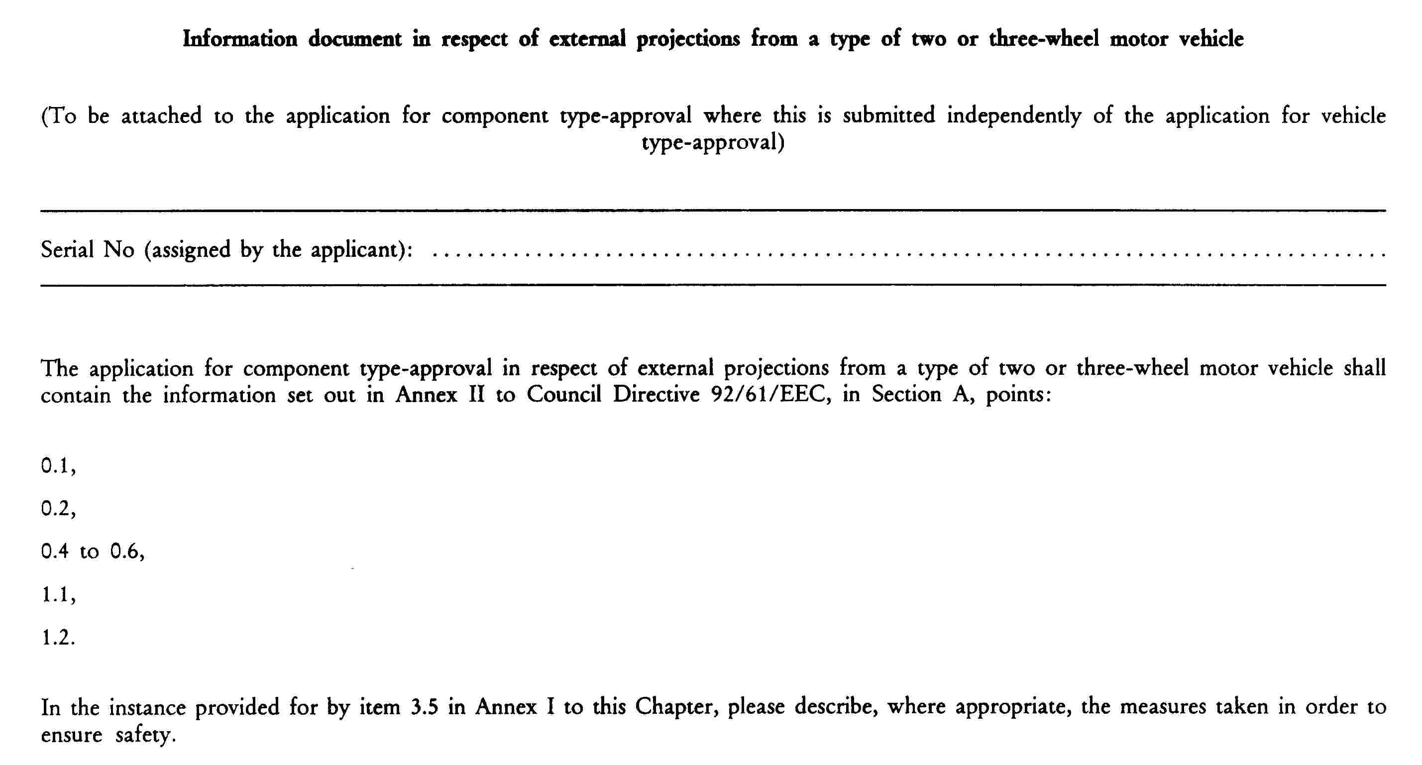
Appendix 2

CHAPTER 4
REAR VIEW MIRRORS FOR TWO OR THREE-WHEEL MOTOR VEHICLES
LIST OF ANNEXES
|
ANNEX I |
Definitions |
|
Appendix |
Procedure for the determination of the radius of curvature ‘r’ of the reflecting surface of the rear view mirror |
|
ANNEX II |
Structural and testing requirements applying to the component type approval of rear view mirrors |
|
Appendix 1 |
Test method intended to determine reflectiveness |
|
Appendix 2 |
Component type-approval and marking of rear view mirrors |
|
Appendix 3 |
Information document in respect of a type of rear view mirror intended for two or three-wheel motor vehicles |
|
Appendix 4 |
Certificate of component type-approval in respect of a type of rear view mirror intended for two or three-wheel motor vehicles |
|
ANNEX III |
Requirements governing the fitting of rear view mirrors to vehicles |
|
Appendix 1 |
Information document in respect of the fitting of a rear view mirror or rear view mirrors to a type of two or three-wheel motor vehicle |
|
Appendix 2 |
Certificate of component type-approval in respect of the fitting of a rear view mirror or rear view mirrors to a type of two or three-wheel motor vehicle |
ANNEX I
DEFINITIONS
|
1. |
‘Rear view mirror’ means a device other than a complex optical system, such as a periscope, the aim of which is to guarantee a clear view towards the rear of the vehicle. |
|
2. |
‘Inside rear view mirror’ means a device as defined in Item 1 which is intended, where appropriate, to be fitted inside the passenger compartment of the vehicle. |
|
3. |
‘Outside rear view mirror’ means a device as defined in Item 1 which is intended to be mounted on an outside surface of the vehicle. |
|
4. |
‘Type of rear view mirror’ means devices which do not differ significantly from one another in respect of the following essential characteristics:
|
|
5. |
‘Class of rear view mirrors’ means all of the devices having in common certain characteristics of functions. These are subdivided as follows: Class I: Inside mirrors, Class L: ‘Main’ outside mirrors. |
|
6. |
‘r’ means the average of the radii of curvature measured on a reflecting surface in accordance with the method described in Item 2 in Appendix 1. |
|
7. |
‘Main radius of curvature at a point on the reflecting surface’ means the values obtained using the apparatus defined in Appendix 1 measured on the major arc of the reflecting surface passing through the centre of that surface and lying within a vertical plane (ri) passing through the centre of that surface, and lying within a horizontal plant, (r′i) and on the major arc which is perpendicular to that segment. |
|
8. |
‘Radius of curvature at a point on the reflecting surface (rp)’ means the arithmetical mean of the main radii of curvature ri and r′i, or in other words:
|
|
9. |
‘Centre of reflecting surface’ means the barycentre of the visible zone of the reflecting surface. |
|
10. |
‘Radius of curvature of the constituent part of the rear view mirror’ means the radius c of the arc of the circle which most closely approximates the rounded form of the part under consideration. |
|
11. |
‘Type of vehicle in respect of rear view mirrors’ means motor vehicles do not differ among themselves in respect of the following essential aspects:
|
|
12. |
‘Driver's ocular points’ means two points 65 mm apart located 635 mm vertically above the R point relating to the driving position defined in the appendix to this Annex. The straight line joining these is at right angles to the vertical median longitudinal plane of the vehicle. The centre of the segment having as its extremities the two ocular points is located within a vertical longitudinal plane which must pass through the centre of the driver's seating position as specified by the manufacturer. |
|
13. |
‘Ambinocular vision’ means the entire field of vision obtained by superimposing the monocular fields for the right and left eyes (see figure below).
|
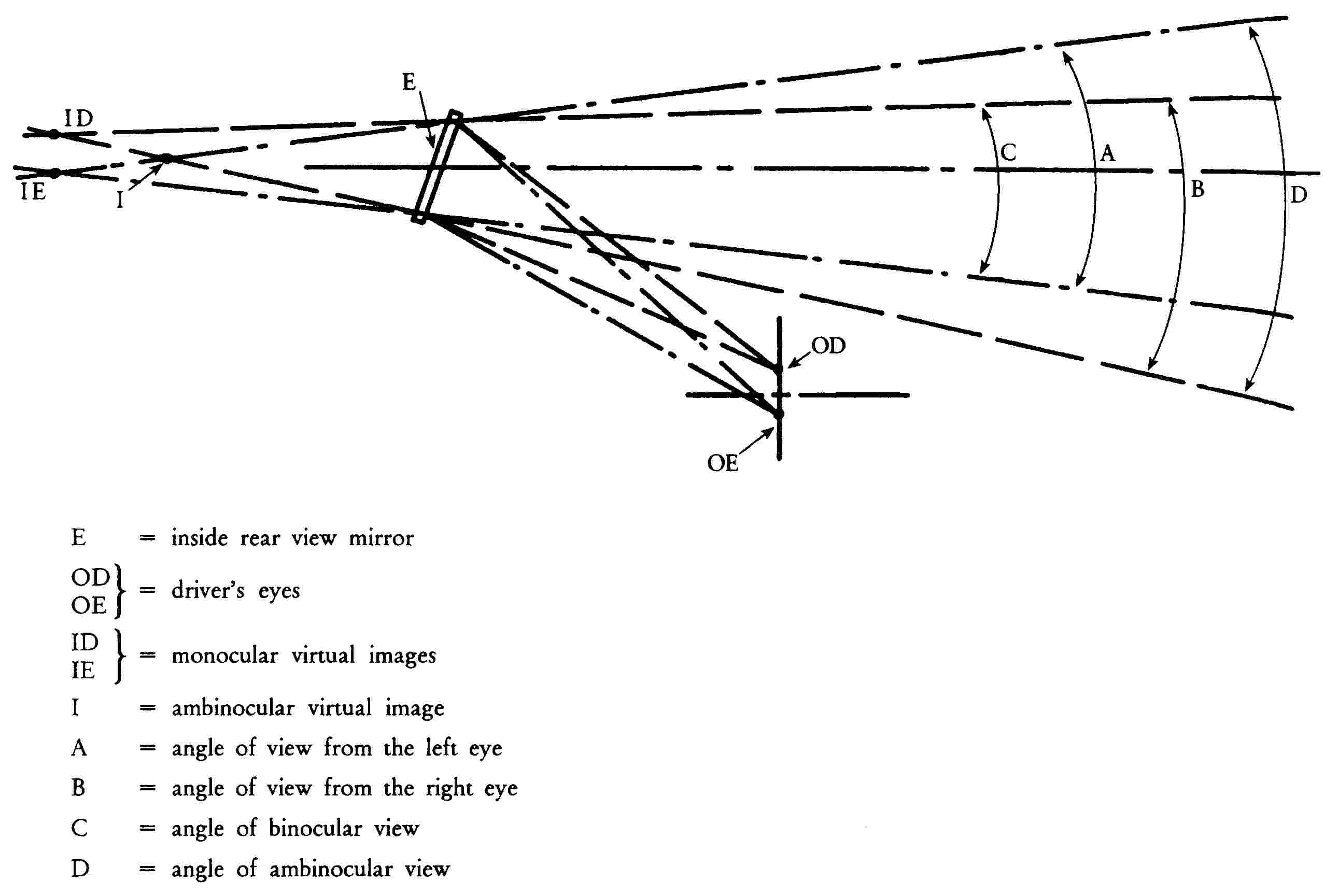
|
14. |
‘Unbodied vehicle’ means a vehicle for which the passenger compartment is not bounded by at least four of all of the following features: windscreen, floor, roof and side and rear walls or doors. |
|
15. |
‘Bodied vehicle’ means a vehicle for which the passenger compartment is bounded or may be bounded by at least four of the following elements: windscreen, floor, roof and side and rear walls or doors. |
Appendix
Procedure for the determination of the radius of curvature ‘r’ of the reflecting surface of the rear view mirror
1. MEASUREMENTS
1.1. Apparatus
The piece of apparatus known as a ‘spherometer’ described in Figure 1 shall be used.
1.2. Measuring points
|
1.2.1. |
The main radii of curvature are measured at three points as close as possible to one-third, one-half and two-thirds of the length of the major arc of the reflecting surface passing through the centre of that surface, in a vertical plane, or of the major arc passing through the centre of that surface, in a horizontal plane, if the latter part is the longer. |
|
1.2.2. |
However, if the dimensions of the reflecting surface make it impossible to obtain the measurements defined in Item 7, the inspecting bodies responsible for the tests may proceed with measurements at this point in two perpendicular directions which are as close as possible to those required above. |
2. CALCULATION OF RADIUS OF CURVATURE ‘r’
‘r’, expressed in millimetres, is calculated via the formula:
![]()
,
where
|
rp1 |
= |
radius of curvature of the first measuring point, |
|
rp2 |
= |
radius of curvature of the second measuring point, |
|
rp3 |
= |
radius of curvature of the third measuring point. |

Figure 1
ANNEX II
STRUCTURAL AND TESTING REQUIREMENTS APPLYING TO THE COMPONENT TYPE-APPROVAL OF REAR-VIEW MIRRORS
1. GENERAL REQUIREMENTS
|
1.1. |
All mirrors shall be adjustable. |
|
1.2. |
The outer edges of the reflecting surface shall be encased in a protective housing (cup, etc.) which, throughout its perimeter, shall at all points and in all directions have a ‘c’ value of not less than 2,5 millimetres. If the reflecting surface protrudes beyond the protective housing, the radius of curvature ‘c’ on the perimeter protruding beyond the protective casing shall be not less than 2,5 mm and the reflecting surface shall retract into the protective housing under a force of 50 Newtons applied to the most protruding point in relation to the protective housing in a horizontal direction approximately parallel to the median longitudinal plane of the vehicle. |
|
1.3. |
With the rear view mirror mounted on a flat surface, all of its parts in all positions of adjustment of the device and all of the parts remaining attached to the supporting base after the test provided for in Item 4.2 which are likely to be struck, under static conditions, by a sphere which is either 165 mm in diameter in the case of inside rear view mirrors or 100 mm in diameter in the case of outside rear view mirrors, shall have a radius of curvature ‘c’ of at least 2,5 mm.
|
|
1.4. |
The device used to attach a rear view mirror to a vehicle shall be designed in such a way that a cylinder 50 mm in radius, the axis of which is one of the swivel or rotation axes enabling the rear view mirror as a whole to swing back in the direction under consideration in the event of impact, shall at least partly intersect the surface to which the device is attached. |
|
1.5. |
The parts of the outside mirrors referred to in Items 1.2 and 1.3 of which the Shore A-hardness does not exceed 60 shall be exempted from the corresponding requirements. |
|
1.6. |
Parts of inside mirrors having a Shore A-hardness of less than 50 and which are attached to rigid supports shall not be subject to the provisions of Items 1.2 and 1.3, save in respect of those supports. |
2. DIMENSIONS
2.1. Inside mirrors (class I)
The reflecting surface shall have dimensions such that it is possible to prescribe on it a rectangle one side of which is 40 mm in length and the other is ‘a’:
![]()
2.2. ‘Main’ outside mirrors (class L)
|
2.2.1. |
The minimum dimensions of the reflecting surface shall be such that:
|
|
2.2.2. |
The maximum dimensions of the reflecting surface shall be such that:
|
3. REFLECTING SURFACE AND COEFFICIENTS OF REFLECTION
|
3.1. |
The reflecting surface of a mirror shall be spherically convex. |
|
3.2. |
The ‘r’ value shall not be less than:
|
|
3.3. |
The value of the coefficient of regular reflection determined in accordance with the method described in Appendix I to this Annex shall not be less than 40 %. If the reflecting surface is of the dipping type (with ‘day’ and ‘night’ positions) it must, in its ‘day’ position, enable the colours of road traffic signs to be recognized. The value of the coefficient of regular reflection in the ‘night’ position shall not be less than 4 %. |
|
3.4. |
The reflecting surface shall retain the characteristics required by Item 3.3 even after prolonged exposure to bad weather under normal conditions of use. |
4. TESTS
|
4.1. |
Rear view mirrors shall be subjected to the tests described in Items 4.2 and 4.3.
|
|
4.2. |
Impact-behaviour test
|
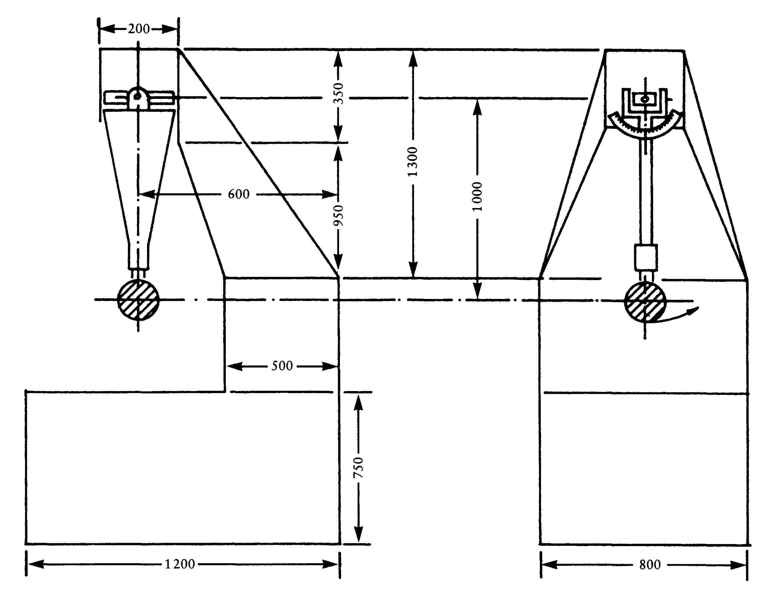
|
4.3. |
Bending test on the protective housing attached to the stem
|

5. TEST RESULTS
|
5.1. |
In the tests provided for in Item 4.2 the pendulum shall continue to swing in such a way that the projection on the release plane and the position adopted by the stem form an angle of at least 20 degrees with the vertical. The angle shall be measured to an accuracy of ± 1 degree.
|
|
5.2. |
During the test provided for in Item 4.2, the remaining part of rear view mirrors glued to windscreens after breakage of the support shall not protrude beyond the base by more than 1 cm and its configuration following the test shall meet the conditions set out in Item 1.3. |
|
5.3. |
During the tests provided for in Items 4.2 and 4.3, the reflecting surface shall not shatter. However, shattering of the reflecting surface is acceptable if either of the following conditions is met:
|
Appendix 1
Test method for determining reflectiveness
1. DEFINITIONS
|
1.1. |
Standardized CIE A ( 60 ): illuminant colorimetric illuminant representing a black body at T68 = 2855,6 Kelvin. |
|
1.2. |
Standardized CIE A (60) : gaseous atmosphere tungsten filament lamp operating at a proximal colour temperature of T68 = 2855,6 Kelvin. |
|
1.3. |
CIE 1931 (60) reference colorimetric observer: radiation receiver the colorimetric characteristics of which correspond to trichromatic spectrum components
|
|
1.4. |
CIE trichromatic spectrum components: trichromatic components, within the CIE (XYZ) system of the monochromatic parts of a spectrum of equal energy. |
|
1.5. |
Photopic vision (60) : normal-eye vision when adapted to luminance levels of at least several candelas per square meter. |
2. APPARATUS
2.1. General
The apparatus shall incorporate a light source, a support for the test piece, a photoelectric cell receiver and an indicator (see Figure 1), together with the necessary means of suppressing the effects of stray light.
The receiver may include an Ulbricht sphere in order to make it easier to measure the coefficient of reflection of non-plane (i.e. convex) rear view mirrors (see Figure 2).
2.2. Spectral characteristics of the light source and receiver
The light source shall be a standardized CIE A source associated with an optical system enabling a beam of almost parallel light rays to be obtained. It is recommended that a voltage stabilizer be provided for in order to maintain a fixed lamp voltage throughout the functioning of the apparatus.
The receiver shall include a photoelectric cell the spectral response of which is proportional to the photopic luminosity function of the CIE (1931) reference colorimetric observer (see table). Any other illuminant-filter-receiver combination providing an overall equivalence to the standardized CIE A illuminant and photopic vision may also be adopted. If the receiver incorporates an Ulbricht sphere, the inner surface of the sphere shall be coated with matt (diffuse) white non-selective paint.
2.3. Geometrical conditions
The beam of incident rays must preferably form an angle (Θ) of 0,44 ± 0,09 radians (25 ± 5o) with the perpendicular to the test surface; this angle must, however, not exceed the upper limit of the tolerance i.e. 0,53 radians or 30o. The axis of the receiver must form an angle (Θ) equal to that of the beam of the incident rays with said perpendicular (see Figure 1). On its arrival at the test surface the incident beam must have a diameter of at least 19 mm. The reflected beam must not be wider than the sensitive surface of the photoelectric cell, must not cover less than 50 % of that surface and must, if possible, cover the same portion of the surface as the beam used to calibrate the instrument.
If the receiver includes an Ulbricht sphere, this shall have a minimum diameter of 127 mm. The openings made for the testpiece and incident beam in the wall of the sphere must be of sufficient size to allow the incident and reflected light beams to pass through in their entirety. The photoelectric cell must be positioned in such a way as not directly to receive the light from the incident or reflected beams.
2.4. Electrical characteristics of the combined cell and indicator
The power of the photoelectric cell displayed on the indicator must be a linear function of the light intensity of the photosensitive surface. Provision must be made for (electrical or optical) means (or both) of easing, resetting and adjusting the calibration settings. These means must not affect the linearity or spectral characteristics of the instrument. These means must not affect the linearity or spectral characteristics of the instrument. The accuracy of the combined receiver and indicator shall be ± 2 % of the full scale or ± 10 % of the value measured in accordance with the smallest value.
2.5. Testpiece support
Its mechanisms must enable the sample to be located in such a way that the axis of the source arm and that of the receiver arm meet at the level of the reflecting surface. That reflecting surface may be within the sample rear view mirror or its two sides, depending on whether this is a primary or secondary surface mirror or a prismatic mirror of the ‘flip’ type.
3. METHOD OF PROCEDURE
3.1. Direct calibration method
Where the direct calibration method is used the reference shall be air. This method can be applied with instruments which have been so devised as to permit calibration at full scale by aligning the receiver directly with the axis of the lights (see Figure 1).
In certain cases (in order, for example, to measure low-reflectiveness surfaces), this method enables an intermediate calibration point to be taken (between 0 and 100 % scale). In these instances it is necessary to interpose a neutral-density filter having a known transmission factor within the optical trajectory and to adjust the calibration system until the indicator shows the percentage transmission corresponding to the neutral-density filter. That filter must be removed before the reflectiveness measurements begin.
3.2. Indirect calibration measurements
This calibration method shall apply to instruments having a source and receiver with a fixed geometrical shape. It requires a suitably calibrated and maintained reflection standard. That standard will preferably be a plane rear view mirror the coefficient of reflection of which is as close as possible to that of the examples tested.
3.3. Measurements on a plane rear view mirror
The coefficient of reflection of plane-mirror test pieces may be measured using instruments employing the principle of direct or indirect calibration. The value of the coefficient of reflection is read directly from the instrument dial.
3.4. Measurements on a non-plane (convex) rear view mirror
Measurement of the coefficient of reflection of non-plane (convex) rear view mirrors requires the use of instruments incorporating an Ulbricht sphere within the receiver (see Figure 2). If with a standard mirror having a coefficient of reflection of E %, the sphere read out gives ne divisions with an unknown mirror, nx divisions will correspond to a coefficient of reflection of X %, as given by the following formula:
![]()
.
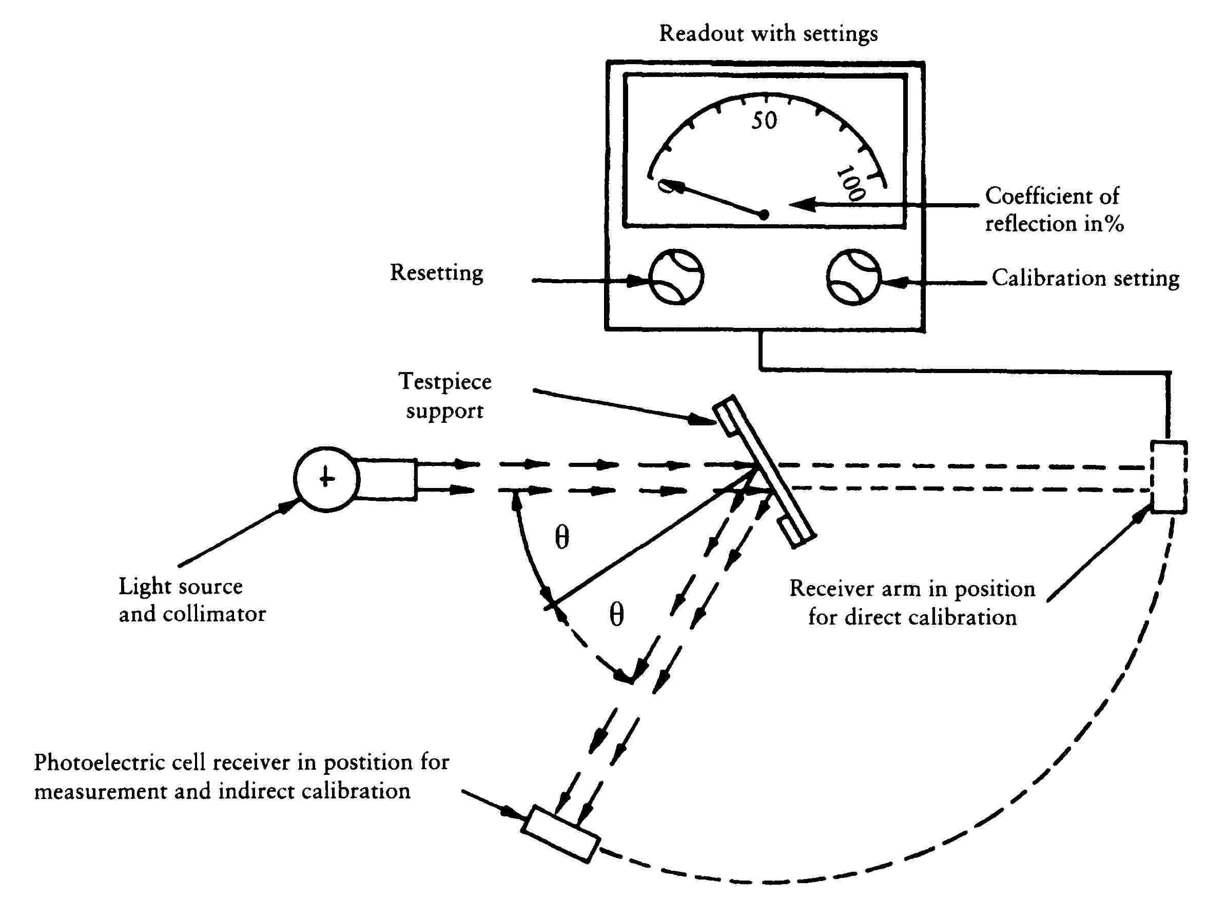
Figure 1: General layout drawing of the reflectivity measuring apparatus using the two calibration methods

Figure 2: General layout drawing of the reflectivity measuring equipment using an Ulbricht sphere in the receiver
Values for the spectral trichromatic components of the CIE 1931 ( 61 ) colorimetric reference observer
This table has been extracted from publication CIE 50 (45) — 1970
|
λ pm |
|
|
|
|
380 |
0,001 4 |
0,000 0 |
0,006 5 |
|
390 |
0,004 2 |
0,000 1 |
0,020 1 |
|
400 |
0,014 3 |
0,000 4 |
0,067 9 |
|
410 |
0,043 5 |
0,001 2 |
0,207 4 |
|
420 |
0,134 4 |
0,004 0 |
0,645 6 |
|
430 |
0,283 9 |
0,011 6 |
1,385 6 |
|
440 |
0,348 3 |
0,023 0 |
1,747 1 |
|
450 |
0,336 2 |
0,038 0 |
1,772 1 |
|
460 |
0,290 8 |
0,060 0 |
1,669 2 |
|
470 |
0,195 4 |
0,091 0 |
1,287 6 |
|
480 |
0,095 6 |
0,139 0 |
0,813 0 |
|
490 |
0,032 0 |
0,208 0 |
0,465 2 |
|
500 |
0,004 9 |
0,323 0 |
0,272 0 |
|
510 |
0,009 3 |
0,503 0 |
0,158 2 |
|
520 |
0,063 3 |
0,710 0 |
0,078 2 |
|
530 |
0,165 5 |
0,862 0 |
0,042 2 |
|
540 |
0,290 4 |
0,954 0 |
0,020 3 |
|
550 |
0,433 4 |
0,995 0 |
0,008 7 |
|
560 |
0,594 5 |
0,995 0 |
0,003 9 |
|
570 |
0,762 1 |
0,952 0 |
0,002 1 |
|
580 |
0,916 3 |
0,870 0 |
0,001 7 |
|
590 |
1,026 3 |
0,757 0 |
0,001 1 |
|
600 |
1,062 2 |
0,631 0 |
0,000 8 |
|
610 |
1,002 6 |
0,503 0 |
0,000 3 |
|
620 |
0,854 4 |
0,381 0 |
0,000 2 |
|
630 |
0,642 4 |
0,265 0 |
0,000 0 |
|
640 |
0,447 9 |
0,175 0 |
0,000 0 |
|
650 |
0,283 5 |
0,107 0 |
0,000 0 |
|
660 |
0,164 9 |
0,061 0 |
0,000 0 |
|
670 |
0,087 4 |
0,032 0 |
0,000 0 |
|
680 |
0,046 8 |
0,017 0 |
0,000 0 |
|
690 |
0,022 7 |
0,008 2 |
0,000 0 |
|
700 |
0,011 4 |
0,004 1 |
0,000 0 |
|
710 |
0,005 8 |
0,002 1 |
0,000 0 |
|
720 |
0,002 9 |
0,001 0 |
0,000 0 |
|
730 |
0,001 4 |
0,000 5 |
0,000 0 |
|
740 |
0,000 7 |
0,000 2 (1) |
0,000 0 |
|
750 |
0,000 3 |
0,000 1 |
0,000 0 |
|
760 |
0,000 2 |
0,000 1 |
0,000 0 |
|
770 |
0,000 1 |
0,000 0 |
0,000 0 |
|
780 |
0,000 0 |
0,000 0 |
0,000 0 |
|
(1) Amended in 1966 (from 3 to 2). |
|||
Appendix 2
Component type-approval and marking of rear view mirrors
1. MARKING
Examples of a type of rear view mirror submitted for component type approval shall, in a clearly legible and indelible manner, receive the manufacturer's trade or brand mark and a space of sufficient size for the component type approval mark; that space shall be identified on the drawings accompanying the request for component type approval.
2. COMPONENT TYPE-APPROVAL
|
2.1. |
The application for component type approval shall be accompanied by four rear view mirrors: three for the tests and one to be kept by the laboratory for any subsequent check which may prove to be necessary. Other examples may be required at the request of the laboratory. |
|
2.2. |
Where the type of rear view mirror submitted in accordance with item 1 above meets the requirements of Annex II component type approval shall be granted and a component type approval number assigned. |
|
2.3. |
This number shall then not be assigned to another type of rear view mirror. |
3. MARKS
|
3.1. |
All rear view mirrors conforming to a type which has been component type approved in pursuance of this chapter shall bear the component type approval mark as described in Annex V to Council Directive 92/61/EEC of 3 June 1992 on the type approval of two or three-wheel motor vehicles. The ‘a’ value defining the dimensions of the rectangle and the figures and letters making up the mark shall be not less than 6 mm large. |
|
3.2. |
The component type approval mark receives an additional symbol I or L specifying the class of rear view mirror type. The additional symbol shall be placed close to the rectangle surrounding letter ‘e’ in any position whatsoever in relation to this. |
|
3.3. |
The component type approval mark and the additional symbol shall be affixed to an essential part of the rear view mirror in such a way that they are indelible and highly visible when the rear view mirror is fitted to the vehicle. |
Appendix 3
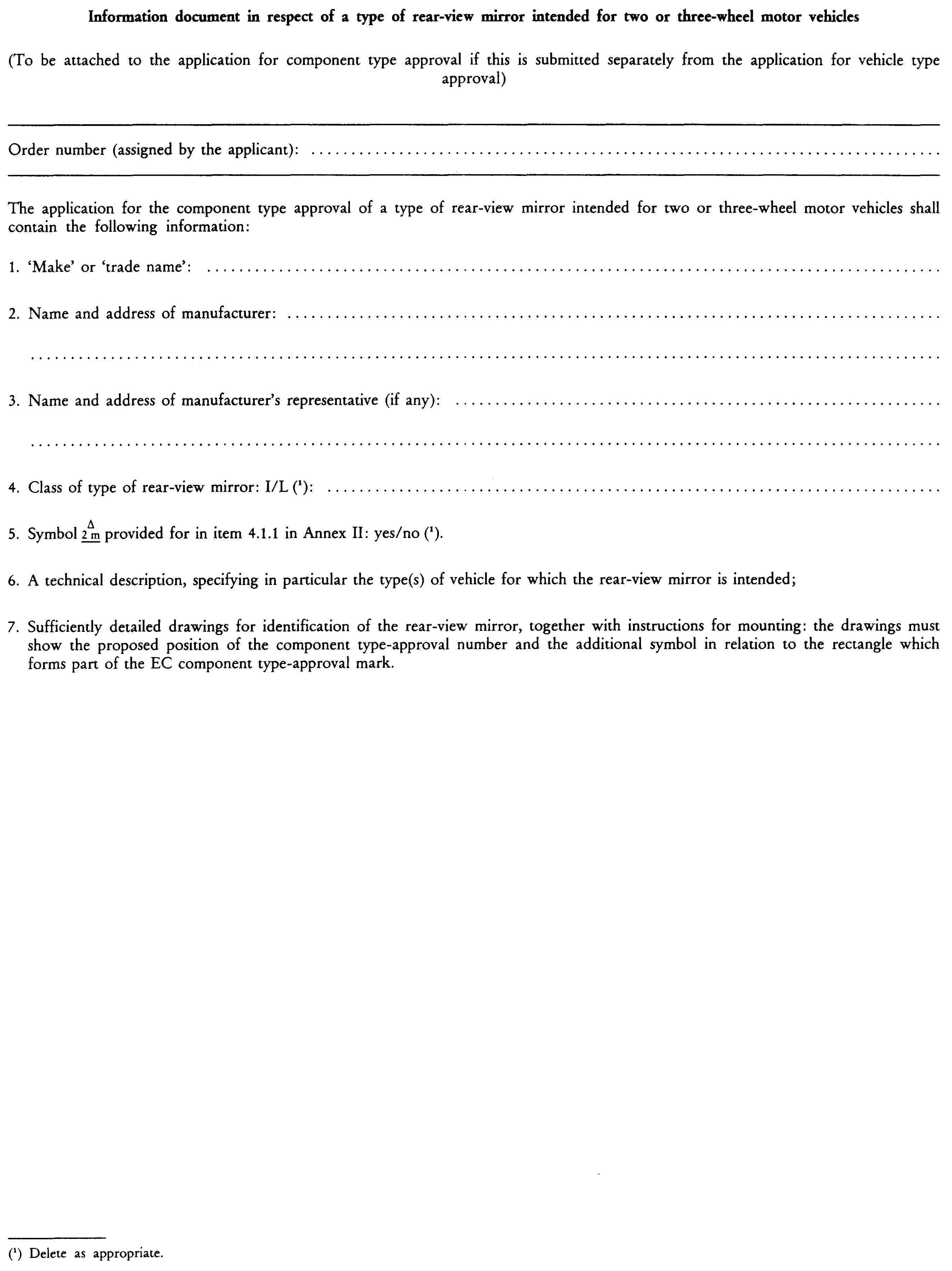
Appendix 4

ANNEX III
REQUIREMENTS GOVERNING THE FITTING OF REAR-VIEW MIRRORS TO VEHICLES
1. POSITION
|
1.1. |
All rear view mirrors shall be attached in such a way that they remain in a stable position under normal vehicle driving conditions. |
|
1.2. |
The rear-view mirror(s) for unbodied vehicles must be fitted or set in such a way that the centre of the reflecting surface is at least 280 mm towards the outside of the median longitudinal plane of the vehicle. Before the measurement the handlebars must remain in the position corresponding to the vehicle's travelling in a straight line and the rear view mirror(s) mut be set in their normal position of use. |
|
1.3. |
Rear-view mirrors must be so placed that the driver, when sitting on the driving seat in a normal driving position, has a clear view of the road to the rear and side(s) of the vehicle. |
|
1.4. |
Exterior rear-view mirrors shall be visible through the side window or through the portion of the windscreen which is swept by the windscreen wiper. |
|
1.5. |
In the case of any vehicle which is in chassis/cab form when the field of vision is measured, the minimum and maximum body widths shall be stated by the manufacturer and, if necessary, simulated by dummy headboards. All vehicles and mirror configurations taken into consideration during the test shall be shown on the EC type-approval certificate for a vehicle with regard to the fitting of rear-view mirrors (see Appendix 2). |
|
1.6. |
The prescribed exterior rear-view mirror on the driver's side of the vehicle must be so located that an angle of not more than 55o is formed between the vertical longitudinal median plane of the vehicle and the vertical plane passing through the centre of the rear-view mirror and through the centre of the straight line 65 mm long which joins the driver's two ocular points. |
|
1.7. |
Rear-view mirrors must not project beyond the external bodywork of the vehicle substantially more than is necessary to comply with the requirements concerning fields of vision laid down in item 4. |
|
1.8. |
Where the lower edge of an exterior rear-view mirror is less than 2 m above the ground when the vehicle is loaded to its maximum permissible all-up weight, this rear-view mirror must not project more than 0,20 m beyond the overall width of the vehicle measured without rear-view mirrors. |
|
1.9. |
Subject to the requirements of items 1.7 and 1.8, rear-view mirrors may project beyond the permissible maximum widths of vehicles. |
2. NUMBER
2.1. Minimum number of rear-view mirrors required for unbodied vehicles
|
Category of vehicle |
Main outside mirror(s) Class L |
|
Moped |
1 |
|
Motorcycle |
2 |
|
Tricycle |
2 |
2.2. Minimum number or rear-view mirrors required for bodied vehicles
|
Category of vehicle |
Inside mirror Class I |
Main outside mirror(s) Class L |
|
Three-wheel mopeds (including light quadricycles) and tricycles |
1 (1) |
1 if there is an inside mirror; 2 if there is not an inside mirror |
|
(1) No inside rear-view mirror is required if the visibility conditions referred to in Item 4.1 below cannot be met. In this case two outside rear-view mirrors are required, one on the left and one on the right hand side of the vehicle. |
||
|
2.3. |
Where a single outside rear view mirror is fitted this shall be located on the left hand side of the vehicle in those Member States where the traffic drives on the right and on the right hand side of the vehicle in those Member States where the traffic drives on the left. |
|
2.4. |
Class I and III rear-view mirrors component type approved in accordance with the provisions of Directive 71/127/EEC relating to rear-view mirrors for motor vehicles are also acceptable for mopeds, motorcycles and tricycles. |
|
2.5. |
Maximum number of optional rear-view mirrors
|
3. ADJUSTMENT
|
3.1. |
Drivers shall be able to adjust rear-view mirrors from their driving position. In the case of three-wheel vehicles having body-work the mirror may be adjusted with the door closed but the window may be open. However, the mirror may in any case be locked in position from the outside. |
|
3.2. |
Rear-view mirrors which can be restored to their original position without adjustment after being pushed backwards are not subject to the requirements of item 3.1. |
4. FIELD OF VISION IN THE CASE OF BODYWORK
4.1. Inside rear-view mirror
4.1.1. Interior rear-view mirror (Class I)
The field of vision must be such that the driver can see at least a 20-m-wide, flat, horizontal portion of the road centred on the vertical longitudinal median plane of the vehicle and extending from 60 m behind the driver's ocular points (Figure 1) to the horizon.
4.2. Outside rear-view mirror
4.2.1. Main exterior rear-view mirrors (Classes L and III).
|
4.2.1.1. |
Left-hand exterior rear-view mirror for vehicles driven on the right of the road and right-hand exterior rear-view mirror for vehicles driven on the left of the road.
|
|
4.2.1.2. |
Right-hand exterior rear-view mirror for vehicles driven on the right and left-hand exterior rear-view mirror for vehicles driven on the left.
|
4.3. Obstructions
4.3.1. Interior rear-view mirror (Class I)
|
4.3.1.1. |
A reduction in the field of vision due to the presence of devices such as head-restraints, sun-visors, rear window wipers and heating elements is permissible, provided that all these devices together do not obscure more than 15 % of the field of vision. |
|
4.3.1.2. |
The degree of obstruction is measured with the headrests adjusted to their lowest possible position and with the sun-visors folded back. |
4.3.2. Exterior rear-view mirrors (Classes L and III)
In the fields of vision specified above, obstruction due to the bodywork and some of its components, such as door handles, outline marker lights, direction indicators and the extremities of rear bumpers, as well as reflective-surface cleaning components, shall not be taken into account if they are responsible for a total obstruction of less than 10 % of the specified field of vision.

Figure 1

Figure 2
Appendix 1

Appendix 2

CHAPTER 5
MEASURES TO BE TAKEN AGAINST AIR POLLUTION CAUSED BY TWO OR THREE-WHEEL MOTOR VEHICLES
LIST OF ANNEXES
|
ANNEX I |
Specifications for measures to be taken against air pollution caused by mopeds |
|
|
Appendix 1 |
Type I test |
|
|
— Sub-appendix 1: |
Operating cycle on dynamometer (Type I test) |
|
|
— Sub-appendix 2: |
Example No 1 of an exhaust-gas collection system |
|
|
— Sub-appendix 3: |
Example No 2 of an exhaust-gas collection system |
|
|
— Sub-appendix 4: |
Method of calibrating the dynamometer |
|
|
Appendix 2 |
Type II test |
|
|
Appendix 3 |
Crankcase gas emissions and interpretation of CO2 emission and fuel consumption test results |
|
|
ANNEX II |
Specifications for measures to be taken against air pollution caused by motorcycles and motor tricycles |
|
|
Appendix 1 |
Type I test |
|
|
— Sub-appendix 1: |
Engine operating cycle for the Type I test |
|
|
— Sub-appendix 2: |
Example No 1 of an exhaust-gas collection system |
|
|
— Sub-appendix 3: |
Example No 2 of an exhaust-gas collection system |
|
|
— Sub-appendix 4: |
Method of calibrating the on-road power absorption by the dynamometer for motorcycles or motor tricycles |
|
|
Appendix 2 |
Type II test |
|
|
Appendix 3 |
Emissions test procedure for hybrid electric motorcycles, motor tricycles and quadricycles |
|
|
— Sub-appendix 1: |
Method for measuring the electricity balance of the battery of OVC and NOVC HEVS |
|
|
— Sub-appendix 2: |
Method of measuring the electric range of vehicles powered by a hybrid electric power train and the OVC range of vehicles powered by a hybrid electric powertrain |
|
|
— Sub-appendix 3: |
Electrical energy storage device State Of Charge (SOC) profile for OVC HEV Type I test |
|
|
ANNEX III |
Specifications for measures to be taken against visible air pollution caused by two or three-wheel motor vehicles equipped with a compression-ignition engine |
|
|
Appendix 1 |
Steady-state operation test over the full-load curve |
|
|
Appendix 2 |
Free-acceleration test |
|
|
Appendix 3 |
Limit values applicable in steady-state tests |
|
|
Appendix 4 |
Specifications for opacimeters |
|
|
Appendix 5 |
Installation and use of the opacimeter |
|
|
ANNEX IV |
Specifications for the reference fuels |
|
|
ANNEX V |
Information document in respect of measures to be taken against air pollution caused by a type of two or three-wheel motor vehicle |
|
|
ANNEX VI |
Component-type approval certificate in respect of measures to be taken against air pollution caused by a type of two or three-wheel motor vehicle |
|
|
ANNEX VII |
type-approval of replacement catalytic converter as separate technical unit for two or three-wheel motor vehicles |
|
|
Appendix 1 |
Information document in respect of a replacement catalytic converter, as separate technical unit(s), for a type of two or three-wheel motor vehicle |
|
|
Appendix 2 |
Type-approval certificate in respect of a replacement catalytic converter, as separate technical unit, for a type of two or three-wheel motor vehicle |
|
|
Appendix 3 |
Examples of type-approval mark |
|
ANNEX I
SPECIFICATIONS FOR MEASURES TO BE TAKEN AGAINST AIR POLLUTION CAUSED BY MOPEDS
1. DEFINITIONS
For the purposes of this Chapter:
|
1.1. |
‘Vehicle type with regard to the emission of gaseous pollutants from the engine’ means mopeds which do not differ in such essential respects as the following:
|
|
1.2. |
‘Reference mass’ means the mass of the moped in running order, increased by a uniform mass of 75 kg. The mass of the moped in running order is its total unladen mass with all tanks filled to at least 90 % of their maximum capacity; |
|
1.3. |
Gaseous pollutants ‘Gaseous pollutants’ means carbon monoxide, hydrocarbons and oxides of nitrogen expressed in terms of nitrogen dioxide (NO2) equivalence; |
|
1.4. |
‘Original equipment catalytic converter’ means a catalytic converter or an assembly of catalytic converters covered by the type-approval delivered for the vehicle; |
|
1.5. |
‘Replacement catalytic converter’ means a catalytic converter or an assembly of catalytic converters intended to replace an original equipment catalytic converter on a vehicle type-approved in accordance with this Chapter, which can be type approved as a separate technical unit as defined in Article 2(5) of Directive 2002/24/EC; |
|
1.6. |
‘Original replacement catalytic converter’ means a catalytic converter or an assembly of catalytic converters whose types are indicated in ► section 4a of Annex VI ◄ but are offered on the market as separate technical units by the holder of the vehicle type-approval. |
2. TEST SPECIFICATIONS
2.1. General
The components liable to affect the emission of gaseous pollutants must be designed, constructed and assembled so as to enable the moped, in normal use, despite the vibrations to which it may be subjected, to comply with the requirements of this Annex.
2.2. Description of tests
|
2.2.1. |
The category L1e, L2e or L6e vehicle in compliance with Euro 3 emissions shall be subjected to Type I and II tests, as specified below: 2.2.1.1. Type I test (average emissions of gaseous pollutants in a congested urban area after cold start) 2.2.1.1.1. The test vehicle is placed on a chassis dynamometer equipped with a brake and a flywheel. The following test procedure shall be carried out: 2.2.1.1.1.1. A cold test phase 1 lasting a total of 448 seconds and comprising four elementary cycles is carried out without interruption; 2.2.1.1.1.2. A warm test phase 2 shall follow cold test phase 1 without delay, lasting a total of 448 seconds and comprising four elementary cycles. The warm test phase 2 shall be carried out without interruption; 2.2.1.1.1.3. Each elementary cycle in cold test phase 1 or in warm test phase 2 shall comprise of seven operations (idle, acceleration, steady speed, deceleration, steady state, deceleration, idle). During both cold and warm test phases the exhaust gases shall be diluted with fresh air to ensure that the flow volume of the mixture remains constant. 2.2.1.1.1.4. In the type I test: 2.2.1.1.1.4.1. A continuous flow of samples of the mixture of exhaust gas and dilution air shall be collected in bag No 1 collected during cold phase 1. A continuous flow of samples of the exhaust gases and dilution air mixture shall be collected in a separate bag No 2 collected during warm phase 2. The concentrations of carbon monoxide, total hydrocarbons, oxides of nitrogen and carbon dioxide in bag No 1 and bag No 2 shall be determined separately one after the other; 2.2.1.1.1.4.2. The total volume of the mixture in each bag shall be measured and added up to produce the total bag volume; 2.2.1.1.1.4.3. At the end of each test phase the distance effectively travelled is recorded from the total shown on the cumulative revolution counter driven by the roller. 2.2.1.1.2. The test is carried out in accordance with the test procedure described in Appendix 1. The gases are collected and analysed according to the methods laid down. 2.2.1.1.3. Subject to the provisions of point 2.2.1.1.4, the test is carried out three times. The total mass of carbon monoxide, hydrocarbons and nitrogen oxides obtained in each test shall be less than the Euro 3 limit values set out in the table below. 2.2.1.1.3.1.
2.2.1.1.3.2. However, one of the three results for each of the abovementioned pollutants may exceed the limit value prescribed for the moped concerned by a maximum of 10 %, provided the arithmetical mean of the three results is less than the prescribed limit value. If more than one pollutant exceeds the prescribed limit values, it is immaterial whether this occurs in the same test or in different tests. 2.2.1.1.4. The number of tests prescribed in point 2.2.1.1.3 is reduced under the conditions described below, where V1 is the result of the first test and V2 is the result of the second test for each of the pollutants referred to in that point. 2.2.1.1.4.1. Only one test is required if V1 ≤ 0,70 L for all the pollutants concerned. 2.2.1.1.4.2. Only two tests are required if V1 ≤ 0,85 L for all the pollutants concerned and if, for at least one pollutant, V1> 0,70 L. In addition, for each of the pollutants concerned, V2 shall be such that V1 + V2 < 1,70 L and V2 < L. 2.2.1.1.5. A category L1e, L2e or L6e vehicle complying with the Euro 3 test type I limits set out in point 2.2.1.1.3.1 and the test type I requirements set out in this Annex shall be approved as Euro 3 compliant.
|
2.3. Diagram and markings
2.3.1. A diagram and a cross-sectional drawing indicating the dimensions of the original equipment catalytic converter(s) (if any) must be annexed to the document referred to in Annex V.
2.3.2. All original equipment catalytic converter(s) shall bear at least the following identifications:
— the ‘e’ mark followed by the identification of the country which granted the type-approval,
— the vehicle manufacturer's name or trade mark,
— the make and identifying part number.
This reference must be legible and indelible and also visible, in the position at which it is to be fitted.
3. CONFORMITY OF PRODUCTION
|
3.1. |
The provisions of paragraph 1 of Annex VI to Council Directive 92/61/EEC of 30 June 1992 on the type-approval of two or three-wheel motor vehicles apply to the checking of conformity of production.
|
4. EXTENSION OF THE SCOPE OF THE APPROVAL
4.1. Vehicle types with different reference masses
The approval may be extended to vehicle types differing from the approved type only in their reference mass provided that the reference mass of the vehicle type for which extension of the approval is requested merely results in the application of the next higher or lower inertia mass equivalents.
4.2. Vehicle types with different total gear ratios
|
4.2.1. |
The approval for a vehicle type may be extended under the following conditions to such vehicle types that differ from the approved type only in their total gear ratios.
|
|
4.2.2. |
If the relationship E ≤ 8 % applies to every gear, the extension must be approved without repeating the Type I tests. |
|
4.2.3. |
Should the gear ratio be E > 8 % for at least one gear and E ≤ 13 % for each gear, the Type I tests must be repeated; however, they may be carried out in a laboratory that the manufacturer may choose himself subject to the agreement of the component approval authority. The test report must be passed to the technical service. |
4.3. Vehicle types with different reference masses and different total gear ratios
The approval for a vehicle type may be extended to cover vehicle types that differ from the approved type only in their reference mass and in their total gear ratios if they comply with the requirements of 4.1 and 4.2.
4.4. Three-wheel mopeds and light quadricycles
The approval granted to two-wheel mopeds may be extended to include three-wheel mopeds and light quadricycles if they use the same engine and the same exhaust system and have the same transmission which differs only in respect of the gear ratio, provided that the reference mass of the vehicle type for which extension of the approval is requested merely results in the application of the next higher or lower inertia mass equivalents.
|
4.5. |
No further extension of approvals may be given to extensions granted in accordance with 4.1 to 4.4. |
5. REPLACEMENT CATALYTIC CONVERTERS AND ORIGINAL REPLACEMENT CATALYTIC CONVERTERS
|
5.1. |
Replacement catalytic converters intended to be fitted to vehicles type-approved in compliance with this Chapter must be tested in accordance with Annex VII. |
|
5.2. |
Original replacement catalytic converters, which are of a type covered by ► section 4a of Annex VI ◄ and are intended for fitment to a vehicle to which the relevant type approval document refers, do not need to comply with Annex VII provided they fulfil the requirements of sections 5.2.1 and 5.2.2 of this Annex. 5.2.1. Markings Original replacement catalytic converters shall bear at least the following identifications: — the ‘e’ mark followed by the identification of the country which granted the type-approval, — the vehicle manufacturer's name or trade mark, — the make and identifying part number. This reference must be legible and indelible and also visible, in the position at which it is to be fitted. ▼M5 ————— 5.2.2. Documentation Original replacement catalytic converters shall be accompanied by the following information: 5.2.2.1. the vehicle manufacturer's name or trade mark; 5.2.2.2. make and identifying part number; 5.2.2.3. the vehicles for which the original replacement catalytic converter is of a type covered by ► section 4a of Annex VI; ◄ 5.2.2.4. installation instructions, where necessary; 5.2.2.5. this information shall be provided either on a leaflet accompanying the original replacement catalytic converter, or, on the packaging in which the original replacement catalytic converter is sold, or, by any other applicable means. |
Appendix 1
Type I test
(checking the average emission of pollutants in a congested urban area)
1. INTRODUCTION
Procedure for Type I test specified in section 2.2.1.1 of Annex I.
2. OPERATING CYCLE ON THE DYNAMOMETER
2.1. Description of cycle
The operating cycle on the dynamometer is as indicated in the following table and plotted in Sub-appendix 1.
Operating cycle on the dynamometer
|
Phase |
Operation |
Acceleration |
Speed |
Duration |
Cumul. time |
||
|
m/s2 |
km/h |
sec |
sec |
||||
|
1 |
Idling |
— |
— |
8 |
8 |
||
|
2 |
Acceleration |
Full throttle |
0—max |
|
— |
||
|
3 |
Steady speed |
Full throttle |
max |
— |
|||
|
4 |
Deceleration |
- 0,56 |
max—20 |
65 |
|||
|
5 |
Steady speed |
— |
20 |
36 |
101 |
||
|
6 |
Deceleration |
- 0,93 |
20—0 |
6 |
107 |
||
|
7 |
Idling |
— |
— |
5 |
112 |
2.2. General conditions for carrying out the cycle
Preliminary testing cycles must be carried out if necessary to determine how best to actuate the accelerator and, if necessary, the gears and brake.
2.3. Use of the gearbox
The gearbox must be used in accordance with the manufacturer's instructions. If there are no manufacturer's instructions the following rules apply:
|
2.3.1. |
Manual gearbox At a steady speed of 20 km/h, the engine speed must as far as possible remain between 50 % and 90 % of the maximum speed. If this speed can be achieved using more than one gear, the moped is tested using the highest gear. During acceleration, the moped is tested using the gear which allows maximum acceleration. The next highest gear must be engaged at the latest when the engine speed has reached 110 % of rated maximum output. During deceleration, the next lowest gear must be engaged before the engine begins to vibrate and at the latest when the engine speed has fallen to 30 % of rated maximum output. First gear must not be engaged during deceleration. |
|
2.3.2. |
Automatic gearbox and torque converter The ‘drive’ setting is used. |
2.4. Tolerances
|
2.4.1. |
A tolerance of 1 km/h above or below the theoretical speed must be allowed during all phases. Speed tolerances greater than those prescribed are permitted during phase changes provided that the tolerances are not exceeded for more than 0,5 s on any one occasion. If the moped decelerates more rapidly than expected without use of the brakes, the procedure specified in 6.2.6.3 applies. |
|
2.4.2. |
Tolerances of 0,5 s above or below the theoretical times are allowed. |
|
2.4.3. |
The speed and time tolerances must be combined as shown in Sub-appendix 1. |
3. MOPED AND FUEL
3.1. Test moped
|
3.1.1. |
The moped must be presented in good mechanical condition. It must have been run in and driven at least 250 km before the test. |
|
3.1.2. |
The exhaust device must not have any leaks likely to reduce the quantity of gases collected, which must equal the quantity of gases emerging from the engine. |
|
3.1.3. |
The leak-tightness of the induction system may be checked to ensure that carburation is not affected by an accidental intake of air. |
|
3.1.4. |
The engine settings and the moped's controls must be those prescribed by the manufacturer. This also applies, in particular, to the idling speed adjustment (rotating speed and carbon monoxide content of exhaust gases), to the automatic choke and to the exhaust gas clean-up system. |
|
3.1.5. |
The laboratory may verify that the moped delivers the performance specified by its manufacturer, that it can be used for normal driving, and more particularly that it is capable of starting when cold and when hot and can idle without stalling. |
3.2. Fuel
The fuel used for the test must be the reference fuel, the specifications for which are set out in Annex IV. If the engine is lubricated by a mixture, the oil added to the reference fuel must comply as to quality and quantity with the manufacturer's recommendations.
4. TEST EQUIPMENT
4.1. Dynamometer
The main characteristics of the dynamometer are as follows:
— load curve equation: on the dynamometer it must be possible, from the initial speed of 12 km/h, to reproduce, with a tolerance of ± 15 %, the power developed by the engine when the moped is travelling along a flat road with a wind speed of virtually zero.
— Otherwise the power absorbed by the brakes and the internal friction of the bench (PA) must be:
—
|
at a speed |
0 < V ≤ 12 km/h: |
|
0 ≤ PA ≤ kV3 12 + 5 % kV3 12 + 5 % PV50 (1) |
|
|
for a speed |
V > 12 km/h: |
|
PA = kV3 ± 5 % kV3 ± 5 % PV50 (1) |
|
|
(1) For a single roller having a diameter of 400 mm. |
|
— without being negative (the calibration method must comply with the provisions of Sub-appendix 4)
— basic inertia: 100 kg
— additional inertias ( 63 ): from 10 kg and 10 kg
— the roller must have a revolution counter which can be reset to zero, so as to measure the distance actually travelled.
4.2. Gas-collection equipment
The gas-collection equipment shall consist of the following components (see Sub-appendices 2 and 3):
4.2.1. A device to collect all the exhaust gases produced during the test, whilst maintaining atmospheric pressure at the moped exhaust outlet (s);
4.2.2. A tube connecting the exhaust-gas collection equipment and the exhaust-gas sampling system. This connecting tube and the gas collection equipment shall be made of stainless steel, or of another material which will not affect the composition of the gases collected and will resist their temperature;
4.2.3. A device to suck in the diluted gases. This device shall guarantee constant flow of a sufficient volume to ensure that all the exhaust gases are sucked in;
|
4.2.4. |
A sampling probe attached to the outside of the gas-collection device which can collect a constant sample of the dilution air using a pump, a filter and a flow meter for the duration of the test; |
|
4.2.5. |
A sampling probe directed upstream of the flow of diluted gases to sample the mixture for the duration of the test at a constant rate of flow using, if necessary, a filter, a flow meter and a pump. The minimum rate of flow of the gases in the two sampling systems described above shall be at least 150 l/h; |
|
4.2.6. |
Three-way valves on the sampling circuits described above to direct the flow of samples either to the atmosphere or to their respective sampling bags for the duration of the test; |
|
4.2.7. |
Leak-tight sampling bags to collect the mixture of exhaust gas and dilution air. These shall be unaffected by the pollutants concerned and of sufficient capacity not to disrupt the normal flow of sampling. There shall be at least one separate sampling bag (bag No 1) for cold test phase 1 and one separate sampling bag (bag No 2) for warm test phase 2; 4.2.7.1. These sampling bags shall each have an automatic sealing device which can be closed rapidly and tightly, either on the sampling circuit or on the analysis circuit at the end of the test. 4.2.7.1.1. The sealing device on bag No 1 shall close after 448 seconds after the start of the type I test. 4.2.7.1.2. The sealing device on bag No 2 shall immediately open subsequent to the sealing of bag No 1 and close again 896 seconds after the start of the type I test; |
|
4.2.8. |
There shall be a method of measuring the total volume of diluted gases passing through the sampling device during the test. The exhaust dilution system shall comply with the requirements of Appendix 2 to Chapter 6 of Annex I to UNECE Regulation No 83. |
|
4.2.9. |
Figure 1 Pollutant emission sampling for Euro 3 as compared with Euro 2 for an L1e, L2e or L6e category vehicle ![Pollution measuring Euro 3Cold (30%)896 secs.Warm (70%)Pollution measuring Euro 2112 secs.448 secs.Vehicle speed (km/h)60504030201000100200300400500600700800900Test Time [s]](./../../../resource.html?uri=celex:01997L0024-20131211.ENG.xhtml.L_2013329EN.01002001.tif.jpg)
|
4.3. Analytical equipment
|
4.3.1. |
The sampling probe may consist of a sampling tube leading into the collecting bags or of a bag-emptying tube. The probe must be of stainless steel or of a material which will not affect the composition of the gases. The sampling probe and the tube connecting it to the analyser must be at ambient temperature. |
|
4.3.2. |
Analysers must be of the following types: — the non-dispersive type with infra-red absorption for carbon monoxide; — the flame-ionization type for hydrocarbons — the chemiluminescent type for oxides of nitrogen. |
|
4.3.3. |
The analytical equipment shall be capable of measuring independently the mixture sample of exhaust gases and dilution air captured in bags No 1 and 2. |
4.4. Accuracy of instruments and measurements
|
4.4.1. |
As the brake is calibrated in a separate test (5.1), it is not necessary to indicate the accuracy of the dynamometer. The total inertia of the rotating masses, including that of the rollers and the rotating part of the brake (see 4.1), must be given to within ± 5 kg. |
|
4.4.2. |
The distance travelled by the moped is determined by the number of revolutions made by the roller to within an accuracy of ± 10 m. |
|
4.4.3. |
The speed of the moped is measured by the speed of rotation of the roller. It must be measurable to within ± 1 km/h for speeds above 10 km/h. |
|
4.4.4. |
Ambient temperature must be measurable to within ± 2 oC. |
|
4.4.5. |
The atmospheric pressure must be measurable to within ± 0,2 kPa. |
|
4.4.6. |
The relative humidity of the ambient air must be measurable to within ± 5 %. |
|
4.4.7. |
Irrespective of the accuracy with which the sampling gases are determined, the accuracy required when measuring the content of the various pollutants must be ± 3 %. The overall response time of the analysing circuit must be less than one minute. |
|
4.4.8. |
The content of the standard (calibration) gases must not differ by more than ± 2 % from the reference value of each gas. The diluents are nitrogen for carbon monoxide and oxides of nitrogen and air for hydrocarbons (propane). |
|
4.4.9. |
The speed of the cooling air must be measurable to within ± 5 km/h. |
|
4.4.10. |
The tolerance allowed over the duration of the gas sampling cycles and operations is ± 1 s. These times must be measurable to an accuracy of 0,1 s. |
|
4.4.11. |
The total volume of the diluted gases must be measurable to within ± 3 %. |
|
4.4.12. |
The total flow and sampling flow must be constant to within ± 5 %. |
5. PREPARING THE TEST
5.1. Setting of brake
The brake must be so adjusted that the speed of the moped on the bench at full throttle is equal to the maximum speed of which it is capable on the road, with a tolerance of ± 1 km/h. This maximum speed may not deviate by more than ± 2 km/h from the rated maximum speed as specified by the manufacturer. If the moped is fitted with a device to govern the maximum speed on the road, the effect of this governor must be taken into account.
The brake may be adjusted using a different method if the manufacturer demonstrates its equivalence.
5.2. Adjustment of equivalent inertias to the moped's translatory inertias.
One or more flywheels are used enabling a total inertia of the rotating masses to be obtained that is proportional to the reference mass of the moped within the following limits:
|
Reference mass of moped RM (kg) |
Equivalent inertias (kg) |
|
RM ≤ 105 |
100 |
|
105 < RM ≤ 115 |
110 |
|
115 < RM ≤ 125 |
120 |
|
125 < RM ≤ 135 |
130 |
|
135 < RM ≤ 145 |
140 |
|
145 < RM ≤ 165 |
150 |
|
165 < RM ≤ 185 |
170 |
|
185 < RM ≤ 205 |
190 |
|
205 < RM ≤ 225 |
210 |
|
225 < RM ≤ 245 |
230 |
|
245 < RM ≤ 270 |
260 |
|
270 < RM ≤ 300 |
280 |
|
300 < RM ≤ 330 |
310 |
|
330 < RM ≤ 360 |
340 |
|
360 < RM ≤ 395 |
380 |
|
395 < RM ≤ 435 |
410 |
|
435 < RM ≤ 475 |
— |
5.3. Cooling the moped
|
5.3.1. |
For the duration of the test, an auxiliary forced-draught device is placed in front of the moped in such a way as to direct a flow of cooling air on to the engine. The air-flow speed is 25 ± 5 km/h. The blower's air outlet must be at least 0,2 m2 in section, with its plane perpendicular to the longitudinal axis of the moped, and it must be placed between 30 and 45 cm ahead of the moped's front wheel. The device for measuring the linear speed of the forced draught must be placed in the middle of the jet of air 20 cm from the air outlet. As far as possible the air speed must be constant across the whole outlet section. |
|
5.3.2. |
The moped may also be cooled using the alternative method described below. A flow of air of variable speed is directed at the moped. The blower must be regulated in such a way that within the operating range, between 10 and 45 km/h inclusive, the linear air speed at the blower outlet is equal to the equivalent roller speed to within ± 5 km/h. At equivalent roller speeds of less than 10 km/h, the forced-draught air speed may be zero. The blower outlet must be at least 0,2 m2 in section and its lower edge between 15 and 20 cm above ground level. The plane of the outlet must be perpendicular to the longitudinal axis of the moped and must be located between 30 and 45 cm in front of the moped's front wheel. |
5.4. Conditioning of the test vehicle
5.4.1. The tyre pressure of the test vehicle shall be as stated by the manufacturer for normal road use. However, if the diameter of the rollers is less than 500 mm, the pressure in the tyres may be increased by 30-50 %.
5.4.2. The fuel tank(s) shall be drained through the drain(s) provided and charged with the test fuel specified in Annex IV.
5.4.3. The test vehicle shall be moved to the test area and the following operations shall be performed:
5.4.3.1. The test vehicle shall be driven or pushed onto a chassis dynamometer and operated through the test cycle set out in 2.1 The test vehicle need not be cold, and may be used to set dynamometer power.
5.4.3.2. The load on the driving wheel shall be within ± 3 kg of the load on a vehicle in normal road use, with a driver weighing 75 kg ± 5 kg, sitting in an upright position.
5.4.3.3. Practice runs over the test cycle set out in 2.1 may be performed at test points, provided an emission sample is not taken, to determine the minimum throttle action required to maintain the proper speed-time relationship.
5.4.3.4. Before being placed in the soak area the test vehicle shall undergo four consecutive operating cycles as set out in 2.1, each lasting 112 seconds. This preconditioning test cycle shall be performed with the dynamometer settings laid down in 5.1 and 5.2 Measurement of the tailpipe emissions is not required for this preconditioning test cycle.
5.4.3.5. Within five minutes of the completion of preconditioning, the test vehicle shall be removed from the dynamometer and driven or pushed to the soak area to be parked. The ambient temperature in the soak area shall be controlled at 298 K ± 5 K. The vehicle shall be stored for not less than six hours and not more than 36 hours prior to the cold start type I test or until the engine oil temperature TOil, the coolant temperature TCoolant or the sparkplug seat/gasket temperature TSP (only for air cooled engines) equals the air temperature of the soak area. The test report shall indicate which of the criteria has been selected.
5.5. Checking of back pressure
|
5.5.1. |
During the preliminary tests a check must be made to ensure that the back pressure set up by the sampling device does not deviate from atmospheric pressure by more than ± 0,75 kPa. |
5.6. Calibration of analytical apparatus
|
5.6.1. |
Calibration of analysers The quantity of gas at the pressure stated to be compatible with the correct functioning of the equipment is injected into the analyser by means of the flow meter and discharge gauge mounted on each bottle. The apparatus must be adjusted to indicate as a stabilized value the value shown on the standard gas bottle. Starting from the setting obtained with the maximum-content bottle, the curve of the analyser's deviations is drawn as a function of the content of the various standard gas bottles used. |
|
5.6.2. |
Overall response time of the apparatus. The gas from the maximum-content bottle is injected into the end of the sampling probe. A check must be made to ensure that the indicated value corresponding to maximum deviation is attained in less than one minute. If this value is not attained, the analysing circuit must be inspected from end to end for leaks. |
6. PROCEDURE FOR DYNAMOMETER TESTS
6.1. Special conditions for carrying out the cycle
|
6.1.1. |
The temperature in the place where the dynamometer is situated must be between 20 and 30 oC throughout the test. |
|
6.1.2. |
The moped must as far as possible be horizontal during the test as to avoid any abnormal distribution of fuel or engine oil. |
|
6.1.3. |
During the test the speed is plotted against time so that the correctness of the cycles performed can be assessed. |
6.2. Starting up the engine
|
6.2.1. |
Once the preliminary operations on the equipment for collecting, diluting, analysing and measuring the gases have been carried out (see 7.1), the engine is started up by means of the devices provided for that purpose, such as the choke, the starter valve, etc., according to the manufaturer's instructions. |
|
6.2.2. |
The taking of samples and the measuring of the flow through the suction device must commence at the beginning of the first cycle. |
|
6.2.3. |
Idling
|
|
6.2.4. |
Accelerations At the end of each idling period, acceleration must be effected by fully opening the throttle and if necessary using the gearbox in such a way as to reach the maximum speed as quickly as possible. |
|
6.2.5. |
Steady speed A steady maximum speed must be maintained by keeping the throttle fully open until the following deceleration phase. During the phase where the speed is kept at a steady 20 km/h, the throttle position must be kept as fixed as possible. |
|
6.2.6. |
Decelerations
|
7. PROCEDURE FOR SAMPLING AND ANALYSIS
7.1. Sampling
7.1.1. Sampling begins as soon as the test commences, as indicated in point 6.2.2.
7.1.2. Bags Nos 1 and 2 shall be hermetically sealed and follow the sealing sequence set out in point 4.2.7.1 They shall not be connected during cold test phase 1 or warm test phase 2.
7.1.3. At the end of the final cycle the device for collecting the diluted exhaust gases and the dilution air shall be closed and the gases produced by the engine diverted into the atmosphere.
7.2. Analysis
|
7.2.1. |
The gases contained in each bag must be analysed as soon as possible and in any event not later than twenty minutes after filling of the bags commenced. |
|
7.2.2. |
If the sampling probe is not left permanently in the bags, the entry of air into the bags during insertion of the probe and the escape of gases from the bags during extraction of the probe must be avoided. |
|
7.2.3. |
The analyser must show a steady value within one minute after being connected up to the bag. |
|
7.2.4. |
The concentrations of HC, CO and NOx and CO2 in the samples of diluted exhaust gases and in the bags collecting the dilution air are determined from the values shown or recorded by the measuring equipment by applying the relevant calibration curves. |
|
7.2.5. |
The value adopted as the content of the gaseous pollutants in the gases analysed is that read off after stabilization of the measuring instrument. |
8. DETERMINATION OF THE QUANTITY OF GASEOUS POLLUTANTS EMITTED
8.1. The masses of CO2 and gaseous pollutants CO, HC, NOx shall be determined separately for bag Nos 1 and 2 in accordance with points 8.2 to 8.6.
8.2. The mass of carbon monoxide gas emitted during the test is determined by means of the formula:
![]()
where:
8.2.1. COm is the mass of carbon monoxide emitted during the test, expressed in g/km, separately to be calculated for each phase;
8.2.2. SX is the distance actually travelled expressed in km, obtained by multiplying the total number of revolutions shown on the revolution counter by the circumference of the roller,
where:
|
X |
= |
1 for cold phase 1; |
|
X |
= |
2 for warm phase 2. |
8.2.3. dCO is the density of carbon monoxide at a temperature of 273,2 K (0 °C) and at a pressure of
![]()
8.2.4. COc is the volume concentration of carbon monoxide in the diluted gases, expressed in parts per million (ppm) and corrected to take account of the pollution of the dilution air:
![]()
where:
8.2.4.1. COe is the concentration of carbon monoxide, measured in ppm, in the sample of diluted gases collected in bag Sa.
8.2.4.2. COd is the concentration of carbon monoxide, measured in ppm, in the sample of dilution air collected in bag Sb.
8.2.4.3. DF is the coefficient defined in 8.6.
8.2.5. V is the volume, expressed in m3/phase, of diluted gases at reference temperature 273,2 K (0 °C) and reference pressure 101,3 kPa:
![]()
where:
8.2.5.1. V0 is the volume of gas displaced by pump P1 during one rotation expressed in m3/revolution. This volume is a function of the differential pressures between the inlet and outlet sections of the pump itself;
8.2.5.2. N is the number of rotations made by pump P1 during the four elementary test cycles of each phase;
8.2.5.3. Pa is the atmospheric pressure expressed in kPa;
8.2.5.4. Pi is the mean value, expressed in kPa, during performance of the drop in pressure in the inlet section of pump P1;
8.2.5.5. Tp (°C) is the value of the temperature of the diluted gases measured in the inlet section of pump P1.
8.3. The mass of unburned hydrocarbons emitted through the moped’s exhaust during the test is calculated by means of the formula:
![]()
where:
8.3.1. HCm is the mass of hydrocarbons emitted during the test, expressed in g, separately to be calculated for each phase;
8.3.2. SX is the distance defined in 8.2.2;
8.3.3. dHC is the density of hydrocarbons at a temperature of 273,2 K (0 °C) and a pressure of 101,3 kPa (for petrol (E5) (C1H1,89O0,016)) (= 631 g/m3);
8.3.4. HCc is the concentration of the diluted gases expressed in ppm carbon equivalent and corrected to take account of the dilution air:
![]()
where:
8.3.4.1. HCe is the concentration of hydrocarbons, expressed in ppm carbon equivalent, in the sample of diluted gases collected in bag Sa;
8.3.4.2. HCd is the concentration of hydrocarbons, expressed in ppm carbon equivalent, in the sample of dilution air collected in bag Sb;
8.3.4.3. DF is the coefficient defined in 8.6.
8.3.5. V is the volume defined in 8.2.5.
8.4. The mass of oxides of nitrogen emitted through the moped’s exhaust during the test is calculated by means of the formula:
![]()
where:
8.4.1. NOxm is the mass of oxides of nitrogen emitted during the test, expressed in g, separately to be calculated each phase;
8.4.2. SX is the distance defined in 8.2.2;
8.4.3. dNO2 is the density of the oxides of nitrogen in the exhaust gases, in NO2 equivalent, at a temperature of 273,2 K (0 °C) and a pressure of 101,3 kPa (= 2,050 103 g/m3);
8.4.4. NOxc is the concentration of oxides of nitrogen in the diluted gases, expressed in ppm and corrected to take account of the dilution air:
![]()
where:
8.4.4.1. NOxe is the concentration of oxides of nitrogen, expressed in ppm, in the sample of diluted gases collected in bag Sa;
8.4.4.2. NOxd is the concentration of oxides of nitrogen, expressed in ppm, in the sample of dilution air collected in bag Sb;
8.4.4.3. DF is the coefficient defined in 8.6.
8.4.5. Kh is the correction factor for humidity
![]()
where:
8.4.5.1. H is the absolute humidity in grams of water per kg of dry air (in g/kg)
![]()
where:
8.4.5.1.1. U is the humidity content expressed as a percentage;
8.4.5.1.2. Pd is the saturated water-vapour pressure, expressed in kPa, at the test temperature;
8.4.5.1.3. Pa is the atmospheric pressure in kPa.
8.4.6. V is the volume defined in 8.2.5.
8.5. Carbon dioxide (CO2)
The mass of carbon dioxide emitted by the vehicle’s exhaust during the test shall be calculated by means of the following formula:
![]()
where:
8.5.1. CO2m is the mass of carbon dioxide emitted during the test part, in g, separately to be calculated for each phase;
8.5.2. SX is the distance defined in 8.2.2;
8.5.3. V is the volume defined in 8.2.5;
8.5.4. dCO2 is the density of the carbon dioxide at a temperature of 273,2 K (0 °C) and a pressure of 101,3 kPa,
![]()
8.5.5. CO2c is the concentration of diluted gases, expressed in per cent carbon dioxide equivalent, corrected to take account of the dilution air by the following equation:
![]()
where:
8.5.5.1. CO2e is the concentration of carbon dioxide expressed in per cent, in the sample of diluted gases collected in bag(s) SA;
8.5.5.2. CO2d is the concentration of carbon dioxide expressed in per cent, in the sample of dilution air collected in bag(s) SB;
8.5.5.3. DF is the coefficient defined in 8.6.
|
8.6. |
DF is a coefficient expressed by means of the formula:
where: 8.6.1. CCO2 = concentration of CO2 in the diluted exhaust gas contained in the sampling bags, expressed in per cent volume; 8.6.2. CHC = concentration of HC in the diluted exhaust gas contained in the sampling bags, expressed in ppm carbon equivalent; 8.6.3. CCO = concentration of CO in the diluted exhaust gas contained in the sampling bags, expressed in ppm. |
|
9. |
PRESENTATION OF TEST RESULTS: The (average) result of the cold phase is named RX1 (in g), the (average) result of the warm phase is named RX2 (in g). Using these emission results the final type I test result RX (in g/km) shall be calculated by means of the following equation:
Where: X = HC, CO, NOx or CO2 RHC_Cold = HCmass_cold_phase_1 (in g) and RHC_Warm = HCmass_warm_phase_2 (in g), see formula in point 8.3 RCO_Cold = COmass_cold_phase_1 (in g) and RCO_Warm = CO mass_warm_phase_2 (in g), see formula in point 8.2 RNOx_Cold = NOxmass_cold_phase_1 (in g) and RNOx_Warm = NOxmass_warm_phase_2 (in g), see formula in point 8.4 RCO2_Cold = CO2mass_cold_phase_1 (in g) and RCO2_Warm = CO2 mass_warm_phase_2 (in g): see formula in point 8.5 ST:
|
|
10. |
FUEL CONSUMPTION The fuel consumption shall be calculated using the test results from point 9 as follows:
where:
|
Sub-appendix 1
Operating cycle on dynamometer (Type I test)

Sub-appendix 2
Example No 1 of an exhaust-gas collection system
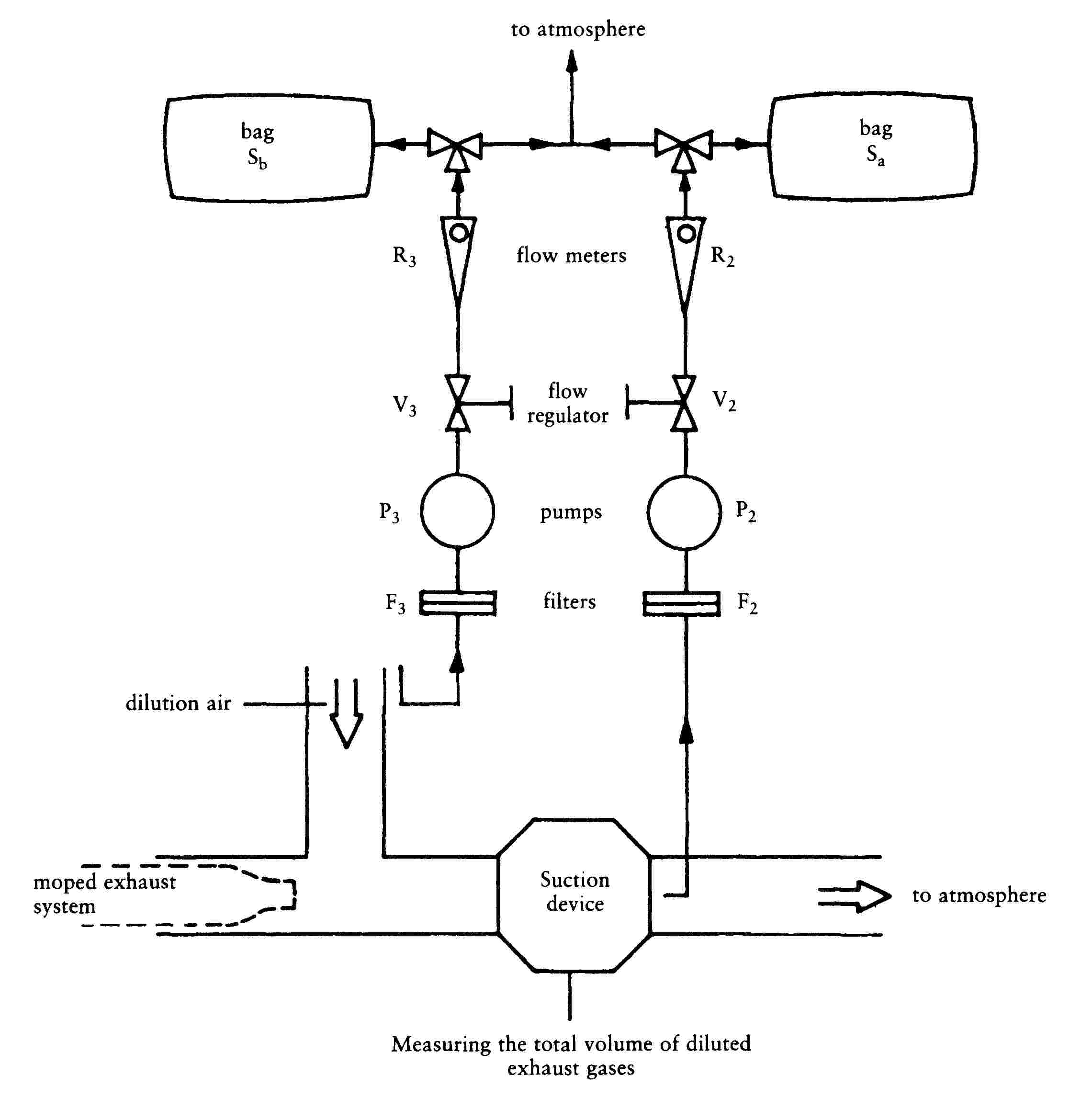
Sub-appendix 3
Example No 2 of an exhaust-gas collection system
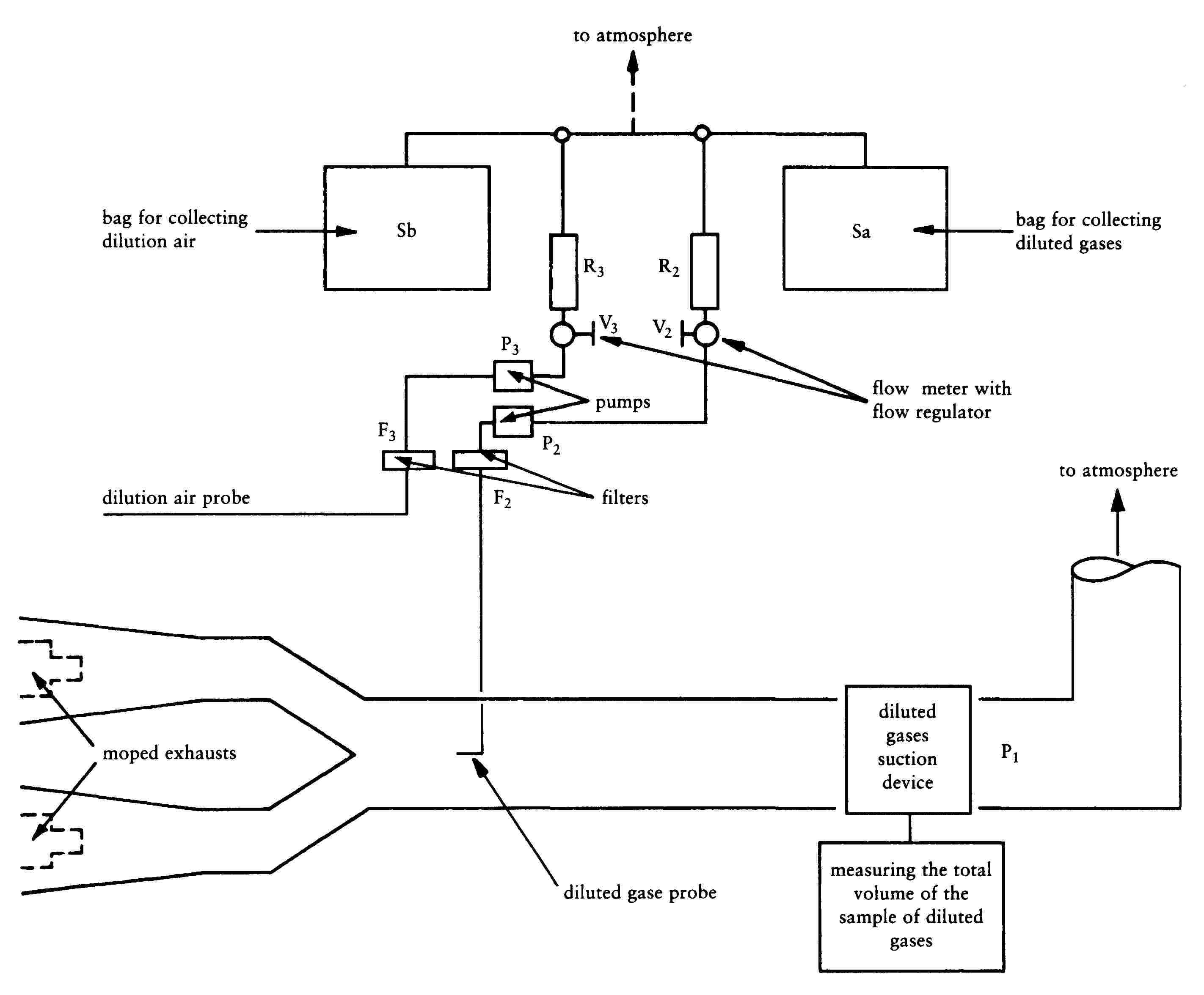
Sub-appendix 4
Method of calibrating the dynamometer
1. PURPOSE
This Sub-appendix describes the method to be used for checking that the curve for the power absorbed by the dynamometer coincides with the absorption curve required under section 4.1 of Appendix 1.
The measured absorbed power includes the power absorbed by friction and the power absorbed by the brake, but does not include the power dissipated by friction between the tyre and the roller.
2. PRINCIPLE OF THE METHOD
This method makes it possible to calculate absorbed power by measuring the roller deceleration time. The kinetic energy of the device is dissipated by the brake and by the friction of the dynamometer. This method does not take account of variations in internal roller friction due to the mass of the moped.
3. PROCEDURE
|
3.1. |
The inertia simulation system corresponding to the mass of the moped being tested is engaged. |
|
3.2. |
The brake is set in accordance with section 5.1. of Appendix 1. |
|
3.3. |
The roller is made to turn at velocity v + 10 km/h. |
|
3.4. |
The roller drive system is disconnected and the roller allowed to decelerate freely. |
|
3.5. |
The time taken by the roller to decelerate from velocity v + 0,1 v to velocity v - 0,1 v is noted. |
|
3.6. |
The absorbed power is calculated by means of the formula:
where:
|
|
3.7. |
The phases described in 3.3. to 3.6. are repeated to cover the range of speeds 10 to 50 km/h, by 10 km/h stages. |
|
3.8. |
The curve representing absorbed power as a function of speed is drawn. |
|
3.9. |
It must be ensured that the curve is within the tolerance specified in section 4.1 of Appendix 1. |
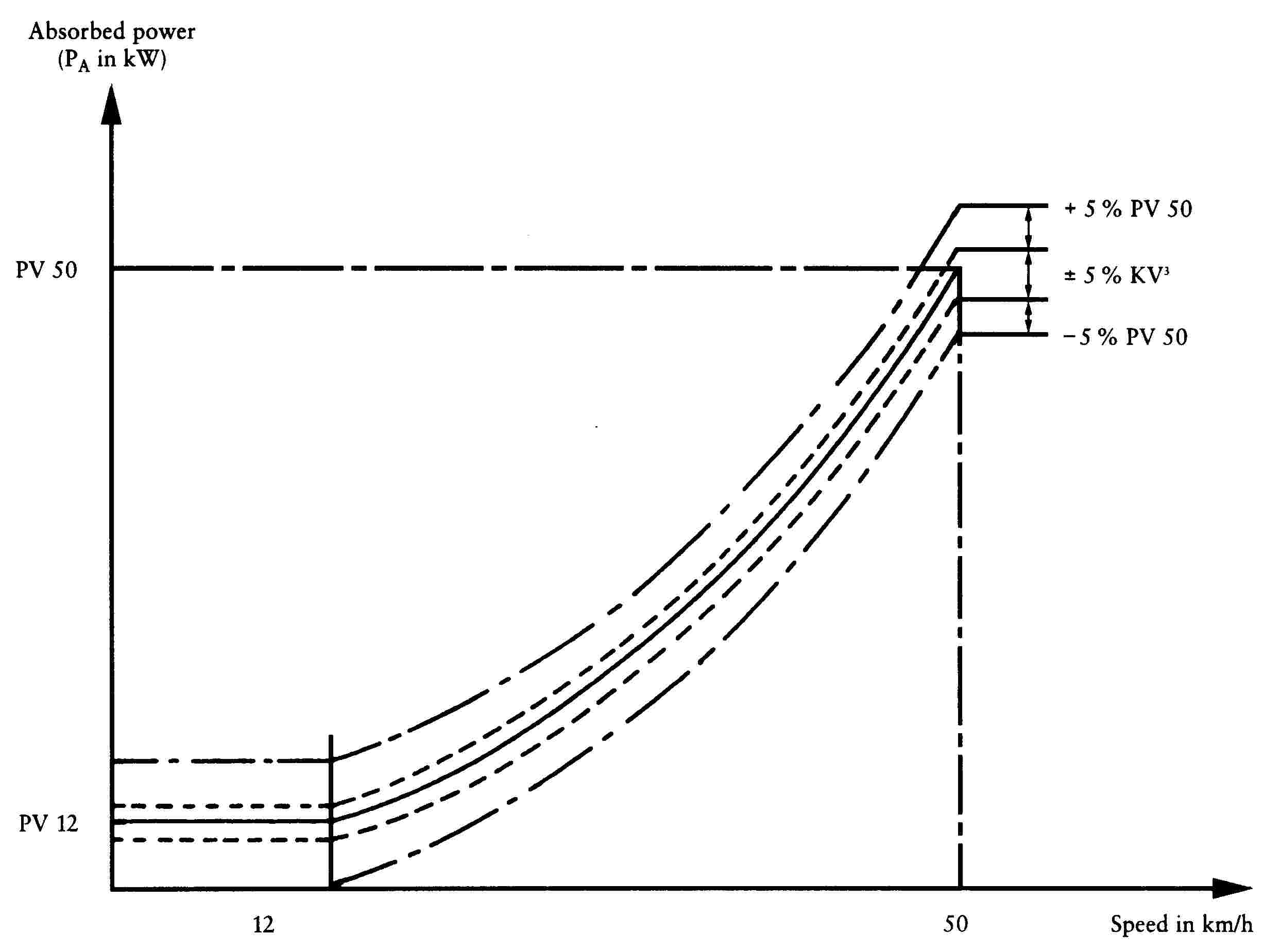
Appendix 2
Type II test
(measuring emissions of carbon monoxide and hydrocarbons at idling speed)
1. INTRODUCTION
Procedure for Type II test specified in section 2.2.1.2. of Annex I.
2. MEASUREMENT CONDITIONS
|
2.1. |
The fuel is that prescribed in section 3.2 of Appendix 1. |
|
2.2. |
The lubricant used must also comply with the provisions of section 3.2. of Appendix 1. |
|
2.3. |
The mass of emissions of carbon monoxide and hydrocarbons must be measured immediately after the Type I test described in section 2.1. of Appendix 1, once the values have stabilized, with the engine at idling speed. |
|
2.4. |
In the case of mopeds with manual transmission gearboxes, the test is carried out with the gear lever in the ‘neutral’ position and the clutch engaged. |
|
2.5. |
In the case of mopeds with automatic transmission gearboxes, the test is carried out with the clutch engaged and the driving wheel immobile. |
|
2.6. |
The idling speed of the engine during the idling period must be adjusted in accordance with the manufacturer's instructions. |
3. SAMPLING AND ANALYSIS OF EXHAUST GASES
|
3.1. |
The electromagnetic valves must be sent in the position for direct analysis of the diluted exhaust gases and the dilution air. |
|
3.2. |
The analyser must show a steady value within one minute after being connected up to the probe. |
|
3.3. |
The concentrations of HC and CO in the samples of diluted exhaust gases and in the dilution air are determined from the values shown or recorded by the measuring equipment by applying the correct calibration curves. |
|
3.4. |
The value adopted as the content of the gaseous pollutants in the gases analysed is that read off after stabilization of the measuring instrument. |
4. DETERMINATION OF THE QUANTITY OF GASEOUS POLLUTANTS EMITTED
|
4.1. |
The mass of carbon monoxide gas emitted during the test is determined by means of the formula:
where:
|
|
4.2. |
The mass of unburnt hydrocarbons emitted through the moped's exhaust during the test is calculated by means of the formula:
where:
|
|
4.3. |
DF is a coefficient expressed by means of the formula:
where:
|
Appendix 3
Crankcase gas emissions and interpretation of CO2 emission and fuel consumption test results
1. Zero crankcase gas emissions shall be emitted from the type-approved vehicle of categories L1e, L2e and L6e. Crankcase gas emissions shall not be discharged directly into the ambient atmosphere from any L-category vehicle throughout its useful life.
2. Interpretation of CO2 emission and fuel consumption test type I results of categories L1e, L2e and L6e vehicles
2.1. The CO2 and fuel consumption values adopted as the type-approval value shall be as declared by the manufacturer provided this is not exceeded by more than four per cent by the value measured by the technical service The measured value may be lower without any limitations.
2.2. If the measured value of CO2 and fuel consumption exceeds the manufacturer’s declared CO2 value and fuel consumption by more than four per cent another test is run on the same vehicle.
2.3. If the average of the two test results does not exceed the manufacturer’s declared value by more than four per cent the value declared by the manufacturer is taken as the type-approval value.
2.4. If the average of the two test results still exceeds the declared value by more than four per cent, a final test is run on the same vehicle. The average of the three test results is taken as the type-approval value.
ANNEX II
SPECIFICATIONS FOR MEASURES TO BE TAKEN AGAINST AIR POLLUTION CAUSED BY MOTORCYCLES AND MOTOR TRICYCLES
1. DEFINITIONS
For the purposes of this Chapter:
|
1.1. |
‘Vehicle type with regard to the limitation of the emission of gaseous pollutants from the engine’ means motorcycles and motor tricycles which do not differ in such essential respects as the following:
|
|
1.2. |
‘Reference mass’ means the mass of the vehicle in running order, increased by a uniform mass of 75 kg. The mass of the motorcycle and motor tricycles in running order is its total unladen weight with all tanks filled to at least 90 % of their maximum capacity; |
|
1.3. |
‘Crankcase’ means the spaces in or external to the engine which are connected to the oil sump by internal or external ducts through which gases and vapours can escape; |
|
1.4. |
‘Gaseous pollutants’ means the exhaust gas emissions of carbon monoxide, oxides of nitrogen expressed in terms of nitrogen dioxide (NO2) equivalent, and hydrocarbons, assuming a ratio of: — C1H1,85 for petrol; — C1H1,86 for diesel; |
|
1.5. |
‘Defeat device’ means a device which measures, senses or responds to operating variables (e.g. vehicle speed, engine speed, gear used, temperature, intake pressure or any other parameter) for the purpose of activating, modulating, delaying or deactivating the operation of any component or function of the emission control system such that the effectiveness of the emission control system is reduced under conditions encountered during normal vehicle use unless the use of such a device is substantially included in the applied emission certification test procedure; |
|
1.6. |
‘Irrational emission control strategy’ means any strategy or measure that, when the vehicle is operated under normal conditions of use, reduces the effectiveness of the emission control system to a level below that expected on the applicable emission test procedure; |
|
1.7. |
‘Original equipment catalytic converter’ means a catalytic converter or an assembly of catalytic converters covered by the type-approval delivered for the vehicle; |
|
1.8. |
‘Replacement catalytic converter’ means a catalytic converter or an assembly of catalytic converters intended to replace an original equipment catalytic converter on a vehicle type-approved in accordance with this Chapter, which can be type-approved as a separate technical unit as defined in Article 2(5) of Directive 2002/24/EC; |
|
1.9. |
‘Original replacement catalytic converter’ means a catalytic converter or an assembly of catalytic converters whose types are indicated in ► section 4a of Annex VI ◄ but are offered on the market as separate technical units by the holder of the vehicle type approval. |
|
1.10. |
‘Hybrid electric vehicle (HEV)’ means a motorcycle, tricycle or quadricycle that, for the purpose of mechanical propulsion, draws energy from both of the following on-vehicle sources of stored energy: (a) a consumable fuel (b) an electrical energy storage device. |
2. TEST SPECIFICATIONS
2.1. General
The components liable to affect the emission of gaseous pollutants must be designed, constructed and assembled so as to enable the motorcycle or motor tricycles, in normal use, despite the vibrations to which it may be subjected, to comply with the requirements of this Annex.
2.2. Description of tests
|
2.2.1. |
Depending on their category and as explained below, the motorcycle or motor tricycle must be subjected to Type I and II tests, as specified below;
▼M1 ————— |
|||||||||||||||||||||||||||||||||||||||||||||||||||||||||||||||||||||||||||||||||||||||||||||||||||||||||||||||||

|
2.3. |
The use of a defeat device and/or irrational emissions control strategy is forbidden.
|
|
2.4. |
Diagram and markings 2.4.1. A diagram and a cross-sectional drawing indicating the dimensions of the original equipment catalytic converter(s) (if any) must be annexed to the document referred to in Annex V. 2.4.2. All original equipment catalytic converter(s) shall bear at least the following identifications: — the ‘e’ mark followed by the identification of the country which granted the type-approval, — the vehicle manufacturer's name or trade mark, — the make and identifying part number. This reference must be legible and indelible and also visible, in the position at which it is to be fitted. |
3. CONFORMITY OF PRODUCTION
|
3.1. |
The requirements set out in section 1 of Annex VI to Directive 92/61/EEC are applicable for checks on the conformity of production.
|
4. EXTENSION OF THE SCOPE OF THE APPROVAL
4.1. Vehicle types with different reference masses
The approval may be extended to vehicle types differing from the approved type only in their reference mass provided that the reference mass of the vehicle type for which the extension of the approval is requested merely results in the application of the next higher or lower inertia mass equivalents.
4.2. Vehicle types with different total gear ratios
|
4.2.1. |
The approval for a vehicle type may be extended under the following conditions to such vehicle types that differ from the approved type only in their total gear ratios.
|
|
4.2.2. |
If the relationship E ≤ 8 % applies to every gear, the extension must be approved without repeating the Type I tests. |
|
4.2.3. |
Should the gear ratio be E > 8 % for at least one gear and E ≤ 13 % for each gear, the Type I tests must be repeated; however, they may be carried out in a laboratory that the manufacturer may choose himself subject to the agreement of the competent approval authority. The test report must be passed to the techncial service. |
4.3. Vehicle types with different reference masses and different total gear ratios
The approval for a vehicle type may be extended to cover vehicle types that differ from the approved type only in their reference mass and in their total gear ratios if they comply with the requirements of 4.1 and 4.2.
4.4. Tricycles and quadricycles other than light quadricycles
The approval granted for two-wheel mopeds may be extended to include tricycles and quadricycles other than light quadricycles if they use the same engine and the same exhaust system and have the same transmission which differs only in respect of the gear ratio, provided that the reference mass of the vehicle type for which extension of the approval is requested merely results in the application of the next higher or lower inertia mass equivalents.
4.5. Restriction
No further extension of approvals may be given to extensions granted in accordance with 4.1 to 4.4.
5. REPLACEMENT CATALYTIC CONVERTERS AND ORIGINAL REPLACEMENT CATALYTIC CONVERTERS
|
5.1. |
Replacement catalytic converters intended to be fitted to vehicles type-approved in compliance with this Chapter must be tested in accordance with Annex VII. |
|
5.2. |
Original replacement catalytic converters, which are of a type covered by ► section 4a of Annex VI ◄ and are intended for fitment to a vehicle to which the relevant type approval document refers, do not need to comply with Annex VII provided they fulfil the requirements of sections 5.2.1 and 5.2.2 of this Annex. 5.2.1. Markings Original replacement catalytic converters shall bear at least the following identifications: — the ‘e’ mark followed by the identification of the country which granted the type-approval, — the vehicle manufacturer's name or trade mark, — the make and identifying part number. This reference must be legible and indelible and also visible, in the position at which it is to be fitted. ▼M5 ————— 5.2.2. Documentation Original replacement catalytic converters shall be accompanied by the following information: 5.2.2.1. the vehicle manufacturer's name or trade mark; 5.2.2.2. make and identifying part number; 5.2.2.3. the vehicles for which the original replacement catalytic converter is of a type covered by ► section 4a of Annex VI; ◄ 5.2.2.4. installation instructions, where necessary; 5.2.2.5. this information shall be provided either on a leaflet accompanying the original replacement catalytic converter, or, on the packaging in which the original replacement catalytic converter is sold, or, by any other applicable means. |
Appendix 1
Type I test (for vehicles tested against the emission limits laid down in Row A of the Table in section 2.2.1.1.5 of this Annex)
(checking the average emission of pollutants)
1. INTRODUCTION
Procedure for Type I test specified in section 2.2.1.1 of Annex II.
|
1.1. |
The motorcycle or motor tricycle is placed on a dynamometer equipped with a brake and flywheel. A test lasting a total of 13 minutes and comprising four cycles is carried out without interruption. Each cycle comprises 15 operations (idling, acceleration, steady speed, deceleration, etc.). During the test the exhaust gases are diluted with air so that the flow volume of the mixture remains constant. Throughout the test a continous flow of samples of the mixture must be passed into a bag so that concentrations (average test values) of carbon monoxide, unburnt hydrocarbons, oxides of nitrogen and carbon dioxide can be determined in succession. |
2. OPERATING CYCLE ON THE DYNAMOMETER
2.1. Description of cycle
The operating cycle on the dynamometer must be that indicated in the following table and plotted in Sub-appendix 1.
2.2. General conditions for carrying out the cycle
Preliminary test cycles must be carried out if necessary to determine how best to actuate the accelerator and brake controls so as to achieve a cycle approximating to the theoretical cycle within the prescribed limits.
2.3. Use of the gearbox
|
2.3.1. |
Use of the gearbox is determined as follows:
|
|
2.3.2. |
Motorcycles or motor tricycles equipped with automatic gearboxes are tested with the highest gear engaged (‘drive’). The accelerator must be operated in such a way as to obtain as steady an acceleration as possible so that the transmission engages the different gears in the normal order. The tolerances specified in 2.4 apply. |
2.4. Tolerances
|
2.4.1. |
A tolerance of ± 1 km/h above or below the theoretical speed is allowed during all phases. Speed tolerances greater than those prescribed are permitted during phase changes provided that the tolerances are never exceeded for more than 0,5 on any one occasion, in all cases subject to the provisions of 6.5.2 and 6.6.3. |
|
2.4.2. |
A tolerance of ± 0,5 seconds above or below the theoretical times must be allowed. |
|
2.4.3. |
The speed and time tolerances are combined as indicated in Sub-appendix 1. |
|
2.4.4. |
The distance travelled during the cycle must be measured with a tolerance of ± 2 %. |
Operating cycle on the dynamometer
|
No of ops |
Operations |
Phase |
Acceleration (m/s2) |
Speed (km/h) |
Duration of each op. phase |
Cum. time (sec) |
Gear to be used in the case of a manual gearbox |
|||||
|
(sec) |
(sec) |
|||||||||||
|
1 |
Idling |
1 |
11 |
11 |
11 |
6 sec. PM/5 sec. K (1) |
||||||
|
2 |
Acceleration |
2 |
1,04 |
0—15 |
4 |
4 |
15 |
|
||||
|
3 |
Steady speed |
3 |
15 |
8 |
8 |
23 |
||||||
|
4 |
Deceleration |
|
-0,69 |
15—10 |
2 |
|
25 |
|||||
|
5 |
Deceleration, clutch diseng. |
- 0,92 |
10—0 |
3 |
28 |
K |
||||||
|
6 |
Idling |
5 |
21 |
21 |
49 |
16 sec. PM/5 sec. K |
||||||
|
7 |
Acceleration |
6 |
0,74 |
0—32 |
12 |
12 |
61 |
|
||||
|
8 |
Steady speed |
7 |
32 |
24 |
24 |
85 |
||||||
|
9 |
Deceleration |
|
- 0,75 |
32—10 |
8 |
|
93 |
|||||
|
10 |
Deceleration, clutch diseng. |
- 0,92 |
10—0 |
3 |
96 |
K |
||||||
|
11 |
Idling |
9 |
21 |
21 |
117 |
16 sec. PM/5 sec. K |
||||||
|
12 |
Acceleration |
10 |
0,53 |
0—50 |
26 |
26 |
143 |
|||||
|
13 |
Steady speed |
11 |
50 |
12 |
12 |
155 |
|
|||||
|
14 |
Deceleration |
12 |
- 0,52 |
50—35 |
8 |
8 |
163 |
|||||
|
15 |
Steady speed |
13 |
35 |
13 |
13 |
176 |
||||||
|
16 |
Deceleration |
|
- 0,68 |
35—10 |
9 |
|
185 |
K |
||||
|
17 |
Deceleration, clutch diseng. |
- 0,92 |
10—0 |
3 |
188 |
|||||||
|
18 |
Idling |
15 |
7 |
7 |
195 |
7 sec. PM |
||||||
|
PM: Gearbox in neutral, clutch engaged. K: Clutch disengaged. |
||||||||||||
3. MOTORCYCLE OR MOTOR TRICYCLE AND FUEL
3.1. Test motorcycle or motor tricycle
|
3.1.1. |
The motorcycle or motor tricycle must be presented in good mechanical condition. It must have been run in and driven at least 1 000 km before the test. The laboratory may decide whether a motorcycle or motor tricycle which has travelled less than 1 000 km before the test may be accepted. |
|
3.1.2. |
The exhaust device must not have any leaks likely to reduce the quantity of gases collected, which must equal the quantity of gases emerging from the engine. |
|
3.1.3. |
The tightness of the intake system may be checked to ensure the carburation is not affected by an accidental intake of air. |
|
3.1.4. |
The settings of the motorcycle or motor tricycle must be as prescribed by the manufacturer. |
|
3.1.5. |
The laboratory may verify that the motorcycle or motor tricycle delivers the performance stated by the manufacturer, that it can be used for normal driving, and more particularly that it is capable of starting when cold and when hot. |
3.2. Fuel
The fuel used for the test must be the reference fuel as defined in Annex IV. If the engine is lubricated by a mixture, the oil added to the reference fuel must comply as to quality and quantity with the manufacturer's recommendations.
4. TEST EQUIPMENT
4.1. Dynamometer
The main characteristics of the dynamometer are as follows:
Contact between roller and tyre of each driving wheel:
— diameter of roller ≥ 400 mm;
— Equation for power-absorption curve: from an initial speed of 12 km/h, the test bench must be able to reproduce, with a tolerance of ± 15 %, the power developed by the engine when the motorcycle or motor tricycle is travelling along a flat road with wind speed virtually zero. Either the power absorbed by the brakes and the internal friction of the bench must be calculated according to the provisions of section 11 of Sub-appendix 4 to Appendix 1, or the power absorbed by the brakes and the internal friction of the bench are:
— K V3 ± 5 % of K V3 ± 5 % of PV50
— Additional inertias: 10 kg and 10 kg ( 65 ).
|
4.1.1. |
The distance effectively travelled is measured using a revolution counter driven by the roller which drives the brake and the flywheels. |
4.2. Equipment for sampling the gases and measuring their volume
|
4.2.1. |
Sub-appendices 2 and 3 contain a diagram showing the principle for collecting, diluting, sampling and measuring the volume of exhaust gases during the test. |
|
4.2.2. |
The following sections describe the components of the test equipment (against each component is given the abbreviation used in the sketch in Sub-appendices 2 and 3). The technical service may authorize the use of different equipment provided that it gives equivalent results:
|
4.3. Analytical equipment
|
4.3.1. |
Measuring the concentration of hydrocarbons
|
|
4.3.2. |
Measuring the concentrations of CO and CO2
|
|
4.3.3. |
Measuring the concentration of NOx
|
4.4. Accuracy of instruments and measurements
|
4.4.1. |
As the brake is calibrated in a separate test, it is not necessary to indicate the accuracy of the dynamometer. The total inertia of the rotating masses, including that of the rollers and the rotating part of the brake (see 5.2), must be given to within ± 2 %. |
|
4.4.2. |
The speed of the motorcycle or motor tricycle is measured by the speed of rotation of the rollers connected to the brake and the flywheels. It must be measurable to within ± 2 km/h from 0 to 10 km/h and to within ± 1 km/h for speeds above 10 km/h. |
|
4.4.3. |
The temperature referred to in 4.2.2.5 must be measurable to within ± 1 oC. The temperaure referred to in 6.1.1 must be measurable to within ± 2 oC. |
|
4.4.4. |
The atmospheric pressure must be measurable to within ± 0,133 kPa. |
|
4.4.5. |
The drop in pressure in the mixture of diluted gases entering pump P1 (see 4.2.2.13) compared with atmospheric pressure must be measurable to within ± 0,4 kPa. The difference in pressure of the diluted gases entering the sections before and after pump P1 (see 4.2.2.13) must be measurable to within ± 0,4 kPa. |
|
4.4.6. |
The volume displaced at each complete rotation of pump P1 and the displacement value at the lowest possible pump speed, as recorded by the revolution counter, must make it possible to determine the overall volume of the mixture of exhaust gases and dilution air displaced by pump P1 during the test to within ± 2 %. |
|
4.4.7. |
Irrespective of the accuracy with which the standard gases are determined, the measuring range of the analysers must be compatible with the accuracy required to measure the content of the various pollutants to within ± 3 %. The flame-ionization analyser which measures the concentration of hydrocarbons must be capable of reaching 90 % of the full scale in less than one second. |
|
4.4.8. |
The content of the standard (calibration) gases must not differ by more than ± 2 % from the reference value of each gas. The diluent must be nitrogen. |
5. PREPARING THE TEST
5.1. Setting of brake
|
5.1.1. |
The brake must be so adjusted that the speed of the motorcycle or motor tricycle during the steady speed phase is between 45 km/h and 55 km/h on a flat dry road. |
|
5.1.2. |
The brake is adjusted as follows:
|
|
5.1.3. |
If the above method is not applicable, the dynamometer must be set in accordance with the values in the table in 5.2. The table shows power values as a function of reference mass at a speed of 50 km/h. This power is determined using the method described in Sub-appendix 4. |
|
5.2. |
Adjustment of equivalent inertias to the translatory inertias of the motorcycle or motor tricycle. One or more flywheels are used enabling a total inertia of the rotating masses to be obtained proportional to the reference mass of the motorcycle or motor tricycle within the following limits:
|
|
5.3. |
Conditioning of the motorcycle or motor tricycle
|
|
5.4. |
Calibration of analytical apparatus
|
6. PROCEDURE FOR DYNAMOMETER TESTS
6.1. Special conditions for carrying out the cycle
|
6.1.1. |
The temperature in the premises where the dynamometer bench is situated must be between 20 o and 30 oC throughout the test, and must be as close as possible to the temperature of the premises where the motorcycle or motor tricycle were conditioned. |
|
6.1.2. |
The motorcycle or motor tricycle must as far as possible be horizontal during the test so as to avoid any abnormal distribution of the fuel. |
|
6.1.3. |
Before initiation of the first pre-conditioning cycle, a flow of air of variable speed is directed at the motorcycle or motor tricycle. Two complete cycles are then performed during which no exhaust gases are collected. The ventilation system must include a mechanism controlled by the speed of the bench roller so that, in the range from 10 km/h to 50 km/h, the linear air speed at the blower outlet is equal to the relative speed of the roller with an approximation of 10 %. For roller speeds below 10 km/h, the air speed may be zero. The end section of the blower device must have the following characteristics: (i) surface area of at least 0,4 m2; (ii) lower edge between 0,15 and 0,20 m above ground level; (iii) distance from the leading edge of the motorcycle or motor tricycle between 0,3 and 0,45 m. |
|
6.1.4. |
During the test, speed is plotted against time in order to check that the cycles have been performed correctly. |
|
6.1.5. |
The temperatures of the cooling water and the crankcase oil may be recorded. |
6.2. Starting up the engine
|
6.2.1. |
Once the preliminary operations on the equipment for collecting, diluting, analysing and measuring the gases have been carried out (see 7.1), the engine is started up by means of the devices provided for that purpose, such as the choke, the starter valve, etc., according to the manufacturer's instructions. |
|
6.2.2. |
The first cycle begins when the taking of samples and the measuring of the pump rotations commence. |
6.3. Use of the manual choke
The choke must be cut out as soon as possible and in principle before acceleration from 0 to 50 km/h. If this requirement cannot be met, the moment of actual cut-out must be indicated. The choke must be adjusted in accordance with the manufacturer's instructions.
6.4. Idling
|
6.4.1. |
Manual-shift gearbox:
|
|
6.4.2. |
Semi-automatic gearboxes: the manufacturer's instructions for driving in town, or in their absence instructions applicable to manual gearboxes, must be followed. |
|
6.4.3. |
Automatic gearboxes: the selector must not be operated at any time during the test unless the manufacturer specifies otherwise. In the latter case the procedure for manual gearboxes applies. |
6.5. Accelerations
|
6.5.1. |
Accelerations must be effected so as to ensure that the rate of acceleration is as constant as possible throughout the operation. |
|
6.5.2. |
If the acceleration capacities of the motorcycle or motor tricycle are not sufficient to perform the acceleration cycles within the prescribed tolerances, the motorcycle or motor tricycle must be driven with the throttle completely open until the speed prescribed for the cycle has been reached; the cycle may then continue normally. |
6.6. Decelerations
|
6.6.1. |
All decelerations must be effected by completely closing the throttle, the clutch remaining engaged. The engine must be disengaged at a speed of 10 km/h. |
|
6.6.2. |
If the period of deceleration is longer than that prescribed for the corresponding phase, the vehicle's brakes are used to keep to the cycle. |
|
6.6.3. |
If the period of deceleration is shorter than that prescribed for the corresponding phase, the timing of the theoretical cycle is restored by a steady-state or an idling period merging into the following steady-state or idling operation. In this case, section 2.4.3 is not applicable. |
|
6.6.4. |
At the end of the deceleration period (stopping motorcycle or motor tricycle on the rollers) the gear is put into neutral and the clutch engaged. |
|
6.7. |
Steady speeds
|
7. PROCEDURE FOR SAMPLING, ANALYSING AND MEASURING THE VOLUME OF EMISSIONS
|
7.1. |
Operations to be carried out before the motorcycle or motor tricycle is started up.
|
|
7.2. |
Beginning of sampling and volume measurement.
|
|
7.3. |
End of sampling and measurement of volume
|
|
7.4. |
Analysis
|
|
7.5. |
Measuring the distance travelled The distance S actually travelled, expressed in km, is obtained by multiplying the total number of revolutions shown on the revolution counter by the size of the roller (see 4.1.1). |
8. DETERMINATION OF THE QUANTITY OF GASEOUS POLLUTANTS EMITTED
|
8.1. |
The mass of carbon monoxide gas emitted during the test is determined by means of the formula:
where:
|
|
8.2. |
The mass of unburnt hydrocarbons emitted through the exhaust of the motorcycle or motor tricycle during the test is calculated by means of the formula:
where:
|
|
8.3. |
The mass of oxides of nitrogen emitted through the exhaust of the motorcycle or motor tricycle during the test is calculated by means of the formula:
where:
|
|
8.4. |
DF is a coefficient expressed by means of the formula:
where:
|
Sub-appendix 1
Engine operating cycle for the Type I test

Sub-appendix 2
Example No 1 of an exhaust-gas collection system

Sub-appendix 3
Example No 2 of an exhaust-gas collection system
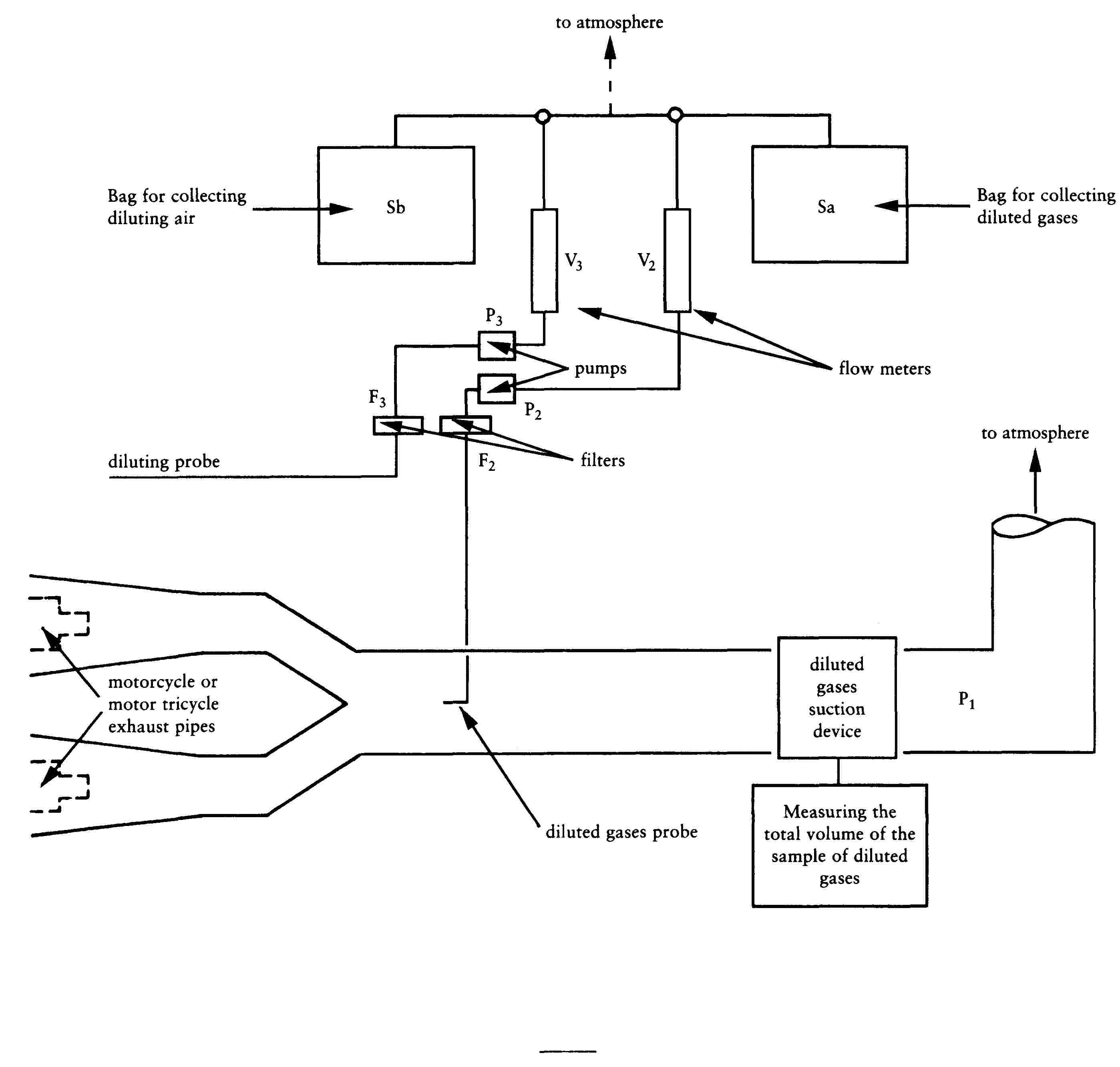
Sub-appendix 4
Method of calibrating the on-road power absorption by the dynamometer in the case of motorcycles or motor tricycles
This Sub-appendix describes a method used to determine on-road power absorption using a dynamometer.
The absorbed power measured on the road includes the power absorbed by friction and the power absorbed by the power absorption device. The dynamometer is operated above the range of test speeds. The device used to activate the dynamometer is then disconnected from the bench and the rotational speed of the roller(s) decreases.
The kinetic energy of the device is dissipated by the dynamometer power absorption unit and by the friction of the dynamometer. This method takes no account of variations in internal friction within the roller due to the rotating mass of the motorcycle or motor tricycle. The difference between the time the free rear-roller stops and the time the motor-driven front roller stops can be ignored in the case of a dynamometer with two rollers.
Procedures are as follows:
1. The rotational speed of the roller is measured if this has not already been done. An additional measuring wheel, a revolution counter, or another method may be used.
2. The motorcycle or motor tricycle is placed on the dynamometer or another method is used to make the dynamometer function.
3. The flywheel, or any other of the inertia simulation systems most commonly used with the dynamometer for the particular category of motorcycle or motor tricycle mass, is engaged.
4. The dynamometer is brought to a speed of 50 km/h.
5. The power absorbed is recorded.
6. The dynamometer is brought to a speed of 60 km/h.
7. The device used to activate the dynamometer is disconnected.
8. The time taken for the dynamometer to decrease from a speed of 55 km/h to a speed of 45 km/h is recorded.
9. The power absorption device is set to a different level.
10. Stages 4 to 9 above are repeated as often as required to cover the range of the on-road powers used.
11. The absorbed power is calculated by means of the formula:
![]()
where:
|
Pd |
= |
power in kW |
|
M1 |
= |
equivalent inertia in kg |
|
V1 |
= |
initial velocity in m/s (55 km/h = 15,28 m/s) |
|
V2 |
= |
final velocity in m/s (45 km/h = 12,50 m/s) |
|
t |
= |
time taken by the roller to decelerate from 55 km/h to 45 km/h |
12. Diagram showing the power absorbed by the dynamometer according to the power indicated for the test speed of 50 km/h referred to in phase 4 below.
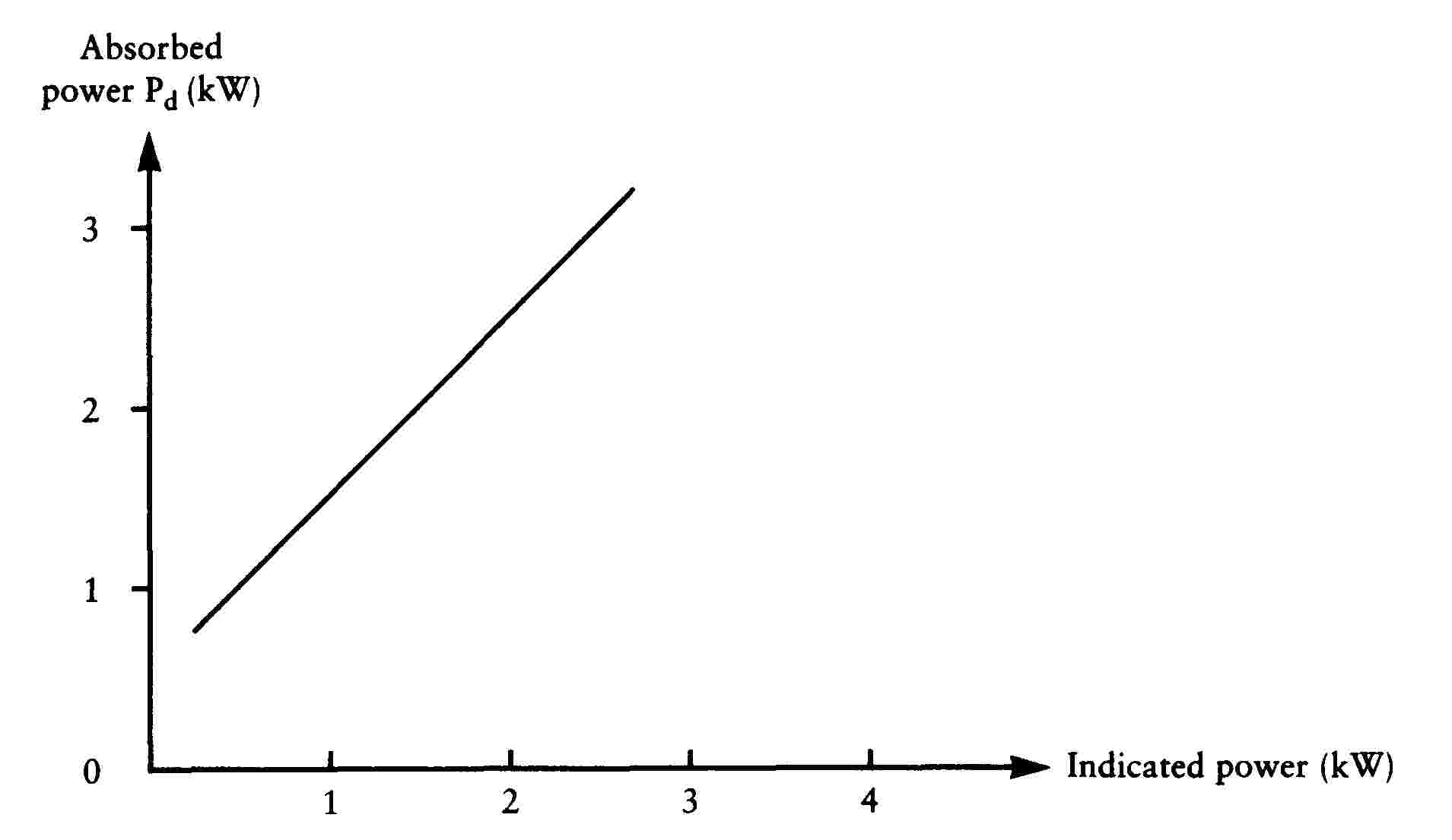
Appendix 1a
Type I test (for vehicles tested against the emission limits laid down in Row B of the Table in section 2.2.1.1.5 of this Annex)
(checking the average emission of pollutants)
1. INTRODUCTION
Procedure for Type I test specified in section 2.2.1.1 of Annex II.
|
1.1. |
The motorcycle or motor tricycle is placed on a dynamometer equipped with a brake and flywheel. A test conducted over six elementary urban cycles lasting a total of 1 170 seconds for class I motorcycles or a test conducted over six elementary urban cycles plus one extra-urban cycle lasting a total of 1 570 seconds for class II motorcycles is carried out without interruption. During the test the exhaust gases are diluted with air so that the flow volume of the mixture remains constant. Throughout the test a continuous flow of samples of the mixture must be passed into one or more bags so that concentrations (average test values) of carbon monoxide, unburnt hydrocarbons, oxides of nitrogen and carbon dioxide can be determined in succession. |
2. OPERATING CYCLE ON THE DYNAMOMETER
2.1. Description of cycle
The operating cycles on the dynamometer are indicated in sub-Appendix 1.
2.2. General conditions for carrying out the cycle
Preliminary test cycles must be carried out if necessary to determine how best to actuate the accelerator and brake controls so as to achieve a cycle approximating to the theoretical cycle within the prescribed limits.
2.3. Use of the gearbox
|
2.3.1. |
Use of the gearbox is determined as follows: 2.3.1.1. At constant speed, the engine speed must as far as possible remain between 50 % and 90 % of the maximum speed. If this speed can be achieved using more than one gear, the engine is tested using the highest gear. 2.3.1.2. With respect to the urban cycle, during acceleration the engine must be tested using the gear which allows maximum acceleration. The next higher gear is engaged, at the latest, when the engine speed has reached 110 % of the speed at which the maximum rated power output occurs. If a motorcycle or motor tricycle reaches a speed of 20 km/h in first gear or 35 km/h in second gear, the next higher gear must be engaged at these speeds. In these cases, no other change into higher gears is permitted. If, during the acceleration phase, the gears are changed at fixed motorcycle or motor tricycle speeds, the steady speed phase which follows must be performed with the gear which is engaged when the motorcycle or motor tricycle begins the steady speed phase, irrespective of the engine speed. 2.3.1.3. During deceleration, the next lower gear must be engaged before the engine reaches virtual idling speed or when the engine speed has fallen to 30 % of the speed of the maximum rated output, whichever occurs first. First gear must not be engaged during deceleration. |
|
2.3.2. |
Motorcycles or motor tricycles equipped with automatic gearboxes are tested with the highest gear engaged (drive). The accelerator must be operated in such a way as to obtain as steady an acceleration as possible so that the transmission engages the different gears in the normal order. The tolerances specified in section 2.4 apply. |
|
2.3.3. |
For carrying out the extra-urban cycle, the gearbox shall be used according to the manufacturer's recommendations. The gear change points shown in Appendix 1 to this Annex do not apply; acceleration must continue throughout the period represented by the straight line connecting the end of each period of idling with the beginning of the next following period of steady speed. The tolerances given in section 2.4 apply. |
2.4. Tolerances
2.4.1. The theoretical speed shall be maintained to a tolerance of ± 2 km/h during all phases. Speed tolerances greater than those prescribed are permitted during phase changes provided that the tolerances are never exceeded for more than 0,5 seconds on any one occasion, in all cases subject to the provisions of sections 6.5.2 and 6.6.3.
2.4.2. A tolerance of ± 0,5 seconds above or below the theoretical times must be allowed.
2.4.3. The speed and time tolerances are combined as indicated in sub-Appendix 1.
2.4.4. The distance travelled during the cycle must be measured with a tolerance of ± 2 %.
3. MOTORCYCLE OR MOTOR TRICYCLE AND FUEL
3.1. Test motorcycle or motor tricycle
3.1.1. The motorcycle or motor tricycle must be presented in good mechanical condition. It should have been run in and driven at least 1 000 km before the test. The laboratory may decide whether a motorcycle or motor tricycle which has travelled less than 1 000 km before the test may be accepted.
3.1.2. The exhaust device must not have any leaks likely to reduce the quantity of gases collected, which must equal the quantity of gases emerging from the engine.
3.1.3. The tightness of the intake system may be checked to ensure the carburation is not affected by an accidental intake of air.
3.1.4. The settings of the motorcycle or motor tricycle must be as prescribed by the manufacturer.
3.1.5. The laboratory may verify that the motorcycle or motor tricycle delivers the performance stated by the manufacturer, that it can be used for normal driving, and more particularly that it is capable of starting when cold and when hot.
3.2. Fuel
The fuel used for the test must be the reference fuel as defined in Annex IV. If the engine is lubricated by a mixture, the oil added to the reference fuel must comply as to quality and quantity with the manufacturer's recommendations.
4. TEST EQUIPMENT
4.1. Dynamometer
The main characteristics of the dynamometer are as follows:
Contact between roller and tyre of each driving wheel:
— diameter of roller ≥ 400 mm;
— Equation for power-absorption curve: from an initial speed of 12 km/h, the test bench must be able to reproduce, with a tolerance of ± 15 %, the power developed by the engine when the motorcycle or motor tricycle is travelling along a flat road with wind speed virtually zero. Either the power absorbed by the brakes and the internal friction of the bench must be calculated according to the provisions of section 11 of sub-Appendix 4 to Appendix 1, or the power absorbed by the brakes and the internal friction of the bench are:
— K V3 ± 5 % of PV50
— Additional inertias: 10 kg and 10 kg ( 66 ).
|
4.1.1. |
The distance effectively travelled is measured using a revolution counter driven by the roller which drives the brake and the flywheels. |
4.2. Equipment for sampling the gases and measuring their volume
4.2.1. Sub-Appendices 2 and 3 of Appendix 1 contain a diagram showing the principle for collecting, diluting, sampling and measuring the volume of exhaust gases during the test.
4.2.2. The following sections describe the components of the test equipment (against each component is given the abbreviation used in the sketch in sub-Appendices 2 and 3 of Appendix 1). The technical service may authorise the use of different equipment provided that it gives equivalent results:
4.2.2.1. a device to collect all the exhaust gases produced during the test; this is generally an open device, which maintains atmospheric pressure at the exhaust pipe(s). Nevertheless, a closed system may be used provided that the back-pressure conditions are complied with (± 1,25 kPa). The gases must be collected in such a way that there is not sufficient condensation to have a significant effect on the nature of the exhaust gases at the test temperature;
4.2.2.2. a tube (Tu) connecting the exhaust-gas collection equipment and the exhaust-gas sampling system. This connecting tube and the gas-collection equipment must be made of stainless steel, or of another material which will not affect the composition of the gases collected and will resist their temperature;
4.2.2.3. a heat exchanger (Sc) capable of limiting the variation in the temperature of the diluted gases at the pump inlet to within ± 5 oC for the duration of the test. This exchanger must be equipped with a pre-heating system capable of bringing the gases up to operating temperature (± 5 oC) before the test commences;
4.2.2.4. a displacement pump (P1) to suck in the diluted gases driven by a motor which can operate at various rigorously constant speeds. The pump must guarantee constant flow of a sufficient volume in order to ensure that all the exhaust gases are sucked in. A device which uses a critical flow venturi may also be used;
4.2.2.5. a device which can continually record the temperature of the diluted gases entering the pump;
4.2.2.6. a sampling probe (S3) attached to the outside of the gas-collection device which can collect a constant sample of the dilution air using a pump, a filter and a flow meter for the duration of the test;
4.2.2.7. a sampling probe S2, placed before the displacement pump and directed upstream of the flow of diluted gases to sample the mixture of diluted gases for the duration of the test at a constant rate of flow using, if necessary, a filter, a flow meter and a pump. The minimum rate of flow of the gases in the two sampling systems described above must be at least 150 l/h;
4.2.2.8. two filters (F2 and F3), placed after probes S2 and S3 respectively, designed to filter out the solid particles suspended in the flow of the sample collected in the bags. Particular care must be taken to ensure that they do not affect the concentrations of gaseous components in the samples;
4.2.2.9. two pumps (P2 and P3) to take samples from probes S2 and S3 respectively and to fill bags Sa and Sb;
4.2.2.10. two hand-adjustable valves (V2 and V3) installed in series with pumps P2 and P3 respectively in order to regulate the flow of the sample sent into the bags;
4.2.2.11. two rotameters (R2 and R3) installed in series in the lines ‘probe, filter, pump, valve, bag’ (S2, F2, P2, V2, Sa and S3, F3, P3, V3, Sb respectively) so that instant visual checks can be made on the flow of the sample at any moment;
4.2.2.12. leak-tight sampling bags to collect the dilution air and mixture of diluted gases which are of sufficient capacity not to disrupt the normal flow of sampling. These sampling bags must have automatic sealing devices on the side of the bag which can be closed rapidly and tightly, either on the sampling circuit or on the analysis circuit at the end of the test;
4.2.2.13.
two differential pressure manometers (g
1and g
2) installed:
|
g1 |
: |
before pump P1 in order to measure the difference in pressure between the mixture of exhaust gases and dilution air and the atmosphere; |
|
g2 |
: |
before and after pump P1 in order to measure the increase in pressure exerted on the flow of gas; |
4.2.2.14. a revolution counter to count the number of revolutions made by the rotary displacement pump P1;
4.2.2.15. three-way valves on the sampling circuits described above to direct the flow of samples either to the atmosphere or to their respective sampling bags for the duration of the test. Rapid-action valves must be used. They must be manufactured from materials which do not affect the composition of the gases; they must also have discharge cross-sections and shapes which minimise load losses as far as technically possible.
4.3. Analytical equipment
4.3.1. Measuring the concentration of hydrocarbons
4.3.1.1. A flame-ionisation analyser is used to measure the concentration of unburnt hydrocarbons in the samples collected in bags Sa and Sb, during the test.
4.3.2. Measuring the concentrations of CO and CO2
4.3.2.1. A non-dispersive infra-red absorption analyser is used to measure the concentrations of carbon monoxide CO and carbon dioxide CO2 in the samples collected in bags Sa and Sb during the test.
4.3.3. Measuring the concentration of NOx
4.3.3.1. A chemiluminescent analyser is used to measure the concentrations of oxides of nitrogen (NOx) in the samples collected in bags Sa and Sb during the test.
4.4. Accuracy of instruments and measurements
|
4.4.1. |
As the brake is calibrated in a separate test, it is not necessary to indicate the accuracy of the dynamometer. The total inertia of the rotating masses, including that of the rollers and the rotating part of the brake (see section 5.2), must be given to within ± 2 %. |
|
4.4.2. |
The speed of the motorcycle or motor tricycle is measured by the speed of rotation of the rollers connected to the brake and the flywheels. It must be measurable to within ± 2 km/h from 0 to 10 km/h and to within ± 1 km/h for speeds above 10 km/h. |
|
4.4.3. |
The temperature referred to in section 4.2.2.5 must be measurable to within ± 1 oC. The temperature referred to in section 6.1.1 must be measurable to within ± 2 oC. |
|
4.4.4. |
The atmospheric pressure must be measurable to within ± 0,133 kPa. |
|
4.4.5. |
The drop in pressure in the mixture of diluted gases entering pump P1 (see section 4.2.2.13) compared with atmospheric pressure must be measurable to within ± 0,4 kPa. The difference in pressure of the diluted gases entering the sections before and after pump P1 (see section 4.2.2.13) must be measurable to within ± 0,4 kPa. |
|
4.4.6. |
The volume displaced at each complete rotation of pump P1 and the displacement value at the lowest possible pump speed, as recorded by the revolution counter, must make it possible to determine the overall volume of the mixture of exhaust gases and dilution air displaced by pump P1 during the test to within ± 2 %. |
|
4.4.7. |
Irrespective of the accuracy with which the standard gases are determined, the measuring range of the analysers must be compatible with the accuracy required to measure the content of the various pollutants to within ± 3 %. The flame-ionisation analyser which measures the concentration of hydrocarbons must be capable of reaching 90 % of the full scale in less than one second. |
|
4.4.8. |
The content of the standard (calibration) gases must not differ by more than ± 2 % from the reference value of each gas. The diluent must be nitrogen. |
5. PREPARING THE TEST
5.1. Road test
5.1.1. Requirement for road
The test road shall be flat, level, straight and smoothly paved. The road surface shall be dry and free of obstacles or wind barriers that might impede the measurement of the running resistance. The slope shall not exceed 0,5 % between any two points at least 2 m apart.
5.1.2. Ambient conditions for road test
During data collecting periods, the wind shall be steady. The wind speed and the direction of the wind shall be measured continuously or with adequate frequency at a location where the wind force during coastdown is representative.
The ambient conditions shall be within the following limits:
— maximum wind speed: 3 m/s
— maximum wind speed for gusts: 5 m/s
— average wind speed, parallel: 3 m/s
— average wind speed, perpendicular: 2 m/s
— maximum relative humidity: 95 %
— air temperature: 278 K to 308 K
Standard ambient conditions shall be as follows:
— pressure, p0: 100 kPa
— temperature, T0: 293 K
— relative air density, d0: 0,9197
— wind speed: no wind
— air volumetric mass, ρ0: 1,189 kg/m3
The relative air density when the motorcycle is tested, calculated in accordance with the formula below, shall not differ by more than 7,5 % from the air density under the standard conditions.
The relative air density, dT, shall be calculated by the formula:
![]()
where
|
dT |
= |
relative air density under test conditions; |
|
pT |
= |
ambient pressure under test conditions, in kilopascals; |
|
TT |
= |
absolute temperature during the test, in Kelvin. |
5.1.3. Reference speed
The reference speed or speeds shall be as defined in the test cycle.
5.1.4. Specified speed
The specified speed, v, is required to prepare the running resistance curve. To determine the running resistance as a function of motorcycle speed in the vicinity of the reference speed v0, running resistances shall be measured using at least four specified speeds, including the reference speed(s). The range of specified speed points (the interval between the maximum and minimum points) shall extend either side of the reference speed or the reference speed range, if there is more than one reference speed, by at least Δv, as defined in 5.1.6. The specified speed points, including the reference speed point(s), shall be no greater than 20 km/h apart and the interval of specified speeds should be the same. From the running resistance curve the running resistance at the reference speed(s) can be calculated.
5.1.5. Coastdown starting speed
The coastdown starting speed shall be more than 5 km/h above the highest speed at which coastdown time measurement begins; since sufficient time is required, for example, to settle the positions of both the motorcycle and rider and to cut the transmitted engine power off before the speed is reduced to v1, the speed at which the measurement of the coastdown time is started.
5.1.6. Coastdown time measurement beginning speed and ending speed
To ensure accuracy in measuring the coastdown time Δt, and coastdown speed interval 2Δv, the beginning speed v1, and ending speed v2, in kilometres per hour, the following requirements shall be met:
![]()
![]()
Δv = 5 km/h for v < 60 km/h
Δv = 10 km/h for v ≥ 60 km/h
5.1.7. Preparation of test motorcycle
5.1.7.1. The motorcycle shall conform in all its components with the production series, or, if the motorcycle is different from the production series, a full description shall be given in the test report.
5.1.7.2. The engine, transmission and motorcycle shall be properly run in, in accordance with the manufacturer's requirements.
5.1.7.3. Motorcycle shall be adjusted in accordance with the manufacturer's requirements, e.g. the viscosity of the oils, tyre pressures, or, if the motorcycle is different from the production series, a full description shall be given in the test report.
5.1.7.4. The mass in running order of the motorcycle shall be as defined in section 1.2 of this Annex.
5.1.7.5. The total test mass including the masses of the rider and the instruments shall be measured before the beginning of the test.
5.1.7.6. The distribution of the load between the wheels shall be in conformity with the manufacturer's instructions.
5.1.7.7. When installing the measuring instruments on the test motorcycle, care shall be taken to minimise their effects on the distribution of the load between the wheels. When installing the speed sensor outside the motorcycle, care shall be taken to minimise the additional aerodynamic loss.
5.1.8. Rider and riding position
|
5.1.8.1. |
The rider shall wear a well-fitting suit (one-piece) or similar clothing, a protective helmet, eye protection, boots and gloves. |
|
5.1.8.2. |
The rider in the conditions given in 5.1.8.1 shall have a mass of 75 kg ± 5 kg and be 1,75 m ± 0,05 m tall. |
|
5.1.8.3. |
The rider shall be seated on the seat provided, with his feet on the footrests and his arms normally extended. This position shall allow the rider at all times to have proper control of the motorcycle during the coastdown test. The position of the rider shall remain unchanged during the whole measurement. |
5.1.9. Measurement of coastdown time
|
5.1.9.1. |
After a warm-up period, the motorcycle shall be accelerated to the coastdown starting speed, at which point the coastdown shall be started. |
|
5.1.9.2. |
Since it can be dangerous and difficult from the viewpoint of its construction to have the transmission shifted to neutral, the coasting may be performed solely with the clutch disengaged. Further, the tractive method of using another motorcycle for traction shall be applied to those motorcycles that have no way of cutting the transmitted engine power off during coasting. When the coastdown test is reproduced on the chassis dynamometer, the transmission and clutch shall be in the same condition on the road test. |
|
5.1.9.3. |
The motorcycle steering shall be altered as little as possible and the brakes shall not be operated until the end of the coastdown measurement. |
|
5.1.9.4. |
The coastdown time Δtai corresponding to the specified speed vj shall be measured as the elapsed time from the motorcycle speed vj+Δv to vj-Δv. |
|
5.1.9.5. |
The procedure from 5.1.9.1 to 5.1.9.4 shall be repeated in the opposite direction to measure the coastdown time Δtbi. |
|
5.1.9.6. |
The average ΔT i of the two coastdown times Δtai and Δtbi shall be calculated by the following equation:
|
|
5.1.9.7. |
At least four tests shall be performed and the average coastdown time ΔT j calculated by the following equation:
Tests shall be performed until the statistical accuracy, P, is equal to or less than 3 % (P ≤ 3 %). The statistical accuracy, P, as a percentage, is defined by:
where:
Table 1 The coefficient for the statistical accuracy
|
|
5.1.9.8. |
In repeating the test, care shall be taken to start the coastdown after observing the same warm-up conditions and at the same coastdown starting speed. |
|
5.1.9.9. |
The measurement of coastdown time for multiple specified speeds may be made by a continuous coastdown. In this case, the coastdown shall be repeated always from the same coastdown starting speed. |
5.2. Data processing
5.2.1. Calculation of running resistance force
|
5.2.1.1. |
The running resistance force Fj, in Newton, at the specified speed vj is calculated as follows:
where:
|
|
5.2.1.2. |
The running resistance force Fj shall be corrected in accordance with 5.2.2. |
5.2.2. Running resistance curve fitting
The running resistance force, F, is calculated as follows:
![]()
This equation shall be fitted by linear regression to the data set of Fj and vj obtained above to determine the coefficients f0 and f2,
where:
|
F |
= |
running resistance force, including wind velocity resistance, if appropriate, in Newton; |
|
f0 |
= |
rolling resistance, in Newton; |
|
f2 |
= |
coefficient of aerodynamic drag, in Newton-hours squared per square kilometre [N/(km/h)2]. |
The coefficients f0 and f2 determined shall be corrected to the standard ambient conditions by the following equations:
![]()
![]()
where:
|
f*0 |
= |
corrected rolling resistance at standard ambient conditions, in Newton; |
|
TT |
= |
mean ambient temperature, in Kelvin; |
|
f*2 |
= |
corrected coefficient of aerodynamic drag in Newton-hours squared per square kilometre [N/(km/h)2]; |
|
pT |
= |
mean atmospheric pressure, in kilo-Pascals; |
|
K0 |
= |
temperature correction factor of rolling resistance, that may be determined based on the empirical data for the particular motorcycle and tyre tests, or may be assumed as follows if the information is not available: K0 = 6 × 10⁻³ K-1. |
5.2.3. Target running resistance force for chassis dynamometer setting
The target running resistance force F*(v0) on the chassis dynamometer at the reference motorcycle speed (v0), in Newton, is determined as follows:
![]()
5.3. Chassis dynamometer setting derived from on-road coastdown measurements
5.3.1. Requirements for equipment
|
5.3.1.1. |
The instrumentation for the speed and time measurement shall have the accuracy specified in Table 2, (a) to (f).
Table 2 Required accuracy of measurements
The chassis dynamometer rollers shall be clean, dry and free from anything which might cause the tyre to slip. |
5.3.2. Inertia mass setting
|
5.3.2.1. |
The equivalent inertia mass for the chassis dynamometer shall be the flywheel equivalent inertia mass, mfi, closest to the actual mass of the motorcycle, ma. The actual mass, ma, is obtained by adding the rotating mass of the front wheel, mrf, to the total mass of the motorcycle, rider and instruments measured during the road test. Alternatively, the equivalent inertia mass mi can be derived from Table 3. The value of mrf may be measured or calculated, in kilograms, as appropriate, or may be estimated as 3 % of m. If the actual mass ma cannot be equalised to the flywheel equivalent inertia mass mi, to make the target running resistance force F* equal to the running resistance force FE which is to be set to the chassis dynamometer, the corrected coastdown time ΔTE may be adjusted in accordance with the total mass ratio of the target coastdown time ΔTroad as follows:
with
and where:
|
|
5.3.3. |
Before the test, the chassis dynamometer shall be appropriately warmed up to the stabilised frictional force Ff. |
|
5.3.4. |
The tyre pressures shall be adjusted to the specifications of the manufacturer or to those at which the speed of the motorcycle during the road test and the motorcycle speed obtained on the chassis dynamometer are equal. |
|
5.3.5. |
The test motorcycle shall be warmed up on the chassis dynamometer to the same condition as it was during the road test. |
|
5.3.6. |
Procedures for setting chassis dynamometer The load on the chassis dynamometer FE is, in view of its construction, composed of the total friction loss Ff which is the sum of the chassis dynamometer rotating frictional resistance, tyre rolling resistance and frictional resistance to the rotating parts in the driving system of the motorcycle, and the braking force of the power absorbing unit (pau) Fpau, as shown in the following equation:
The target running resistance force F* in 5.2.3 should be reproduced on the chassis dynamometer in accordance with the motorcycle speed. Namely:
5.3.6.1. Determination of total friction loss The total friction loss Ff on the chassis dynamometer shall be measured by the method given in sections 5.3.6.1.1 and 5.3.6.1.2. 5.3.6.1.1. Motoring by chassis dynamometer This method applies only to chassis dynamometers capable of driving a motorcycle. The motorcycle shall be driven by the chassis dynamometer steadily at the reference speed v0 with the transmission engaged and the clutch off. The total friction loss Ff(v0) at the reference speed v0 is given by the chassis dynamometer force. 5.3.6.1.2. Coastdown without absorption The method of measuring the coastdown time is regarded as the coastdown method for the measurement of the total friction loss Ff. The motorcycle coastdown shall be performed on the chassis dynamometer by the procedure described from 5.1.9.1 to 5.1.9.4 under zero chassis dynamometer absorption, and the coastdown time Δti corresponding to the reference speed v0 shall be measured. The measurement shall be carried out at least three times, and the mean coastdown time
The total friction loss Ff(v0) at the reference speed v0 is calculated as:
5.3.6.2. Calculation of power absorption unit force The force Fpau(v0) to be absorbed by the chassis dynamometer at the reference speed v0 is calculated by subtracting Ff(v0) from the target running resistance force F*(v0):
5.3.6.3. Chassis dynamometer setting According to the type of chassis dynamometer, it shall be set by one of the methods described in sections 5.3.6.3.1 to 5.3.6.3.4. 5.3.6.3.1. Chassis dynamometer with polygonal function In the case of a chassis dynamometer with polygonal function, in which the absorption characteristics are determined by load values at several speed points, at least three specified speeds, including the reference speed, shall be chosen as the setting points. At each setting point, the chassis dynamometer shall be set to the value Fpau(vj) obtained in 5.3.6.2. 5.3.6.3.2. Chassis dynamometer with coefficient control 5.3.6.3.2.1. In the case of a chassis dynamometer with coefficient control, in which the absorption characteristics are determined by given coefficients of a polynomial function, the value of Fpau(vj) at each specified speed shall be calculated by the procedure given in sections 5.3.6.1 and 5.3.6.2. 5.3.6.3.2.2. Assuming the load characteristics to be:
the coefficients a, b and c shall be determined by the polynomial regression method. 5.3.6.3.2.3. The chassis dynamometer shall be set to the coefficients a, b and c obtained in section 5.3.6.3.2.2. 5.3.6.3.3. Chassis dynamometer with F* polygonal digital setter 5.3.6.3.3.1. In the case of a chassis dynamometer with F* polygonal digital setter, where a CPU is incorporated in the system, F* is input directly, and Δti, Ff and Fpau are automatically measured and calculated to set on the chassis dynamometer the target running resistance force F*=f*0+f*2v2. 5.3.6.3.3.2. In this case, several points are directly input in succession digitally by the data set of F*j and vj, the coastdown is performed and the coastdown time Δti is measured. By automatic calculation in the following sequence by the built-in CPU, Fpau is automatically set in the memory at motorcycle speed intervals of 0,1 km/h, and after the coastdown test is repeated several times, the running resistance setting is computed:
5.3.6.3.4. Chassis dynamometer with f*0, f*2 coefficient digital setter 5.3.6.3.4.1. In the case of a chassis dynamometer with f*0, f*2 coefficient digital setter, where a CPU is incorporated in the system, the target running resistance force F*=f*0+f*2v2 is automatically set on the chassis dynamometer. 5.3.6.3.4.2. In this case, the coefficients f*0 and f*2 are directly input digitally; the coastdown is performed and the coastdown time Δti is measured. The calculation is automatically made in the following sequence by the built-in CPU and Fpau is automatically set in the memory digitally at motorcycle speed intervals of 0,06 km/h to complete the running resistance setting:
|
|
5.3.7. |
Verification of chassis dynamometer
|
5.4. Chassis dynamometer setting using the running resistance table
The chassis dynamometer can be set by the use of the running resistance table instead of the running resistance force obtained by the coastdown method. In this table method, the chassis dynamometer shall be set by the reference mass regardless of particular motorcycle characteristics.
The flywheel equivalent inertia mass mfi shall be the equivalent inertia mass mi specified in Table 3. The chassis dynamometer shall be set by the rolling resistance of front wheel ‘a’ and the aerodynamic drag coefficient ‘b’ specified in Table 3.
Table 3 (1)
Equivalent inertia mass
|
Reference mass mref (kg) |
Equivalent inertia mass mi (kg) |
Rolling resistance of front wheel ‘a’ (N) |
Aerodynamic drag coefficient ‘b’ (N/(km/h) (1) |
|
95 < mref ≤ 105 |
100 |
8,8 |
0,0215 |
|
105 < mref ≤ 115 |
110 |
9,7 |
0,0217 |
|
115 < mref ≤ 125 |
120 |
10,6 |
0,0218 |
|
125 < mref ≤ 135 |
130 |
11,4 |
0,0220 |
|
135 < mref ≤ 145 |
140 |
12,3 |
0,0221 |
|
145 < mref ≤ 155 |
150 |
13,2 |
0,0223 |
|
155 < mref ≤ 165 |
160 |
14,1 |
0,0224 |
|
165 < mref ≤ 175 |
170 |
15,0 |
0,0226 |
|
175 < mref ≤ 185 |
180 |
15,8 |
0,0227 |
|
185 < mref ≤ 195 |
190 |
16,7 |
0,0229 |
|
195 < mref ≤ 205 |
200 |
17,6 |
0,0230 |
|
205 < mref ≤ 215 |
210 |
18,5 |
0,0232 |
|
215 < mref ≤ 225 |
220 |
19,4 |
0,0233 |
|
225 < mref ≤ 235 |
230 |
20,2 |
0,0235 |
|
235 < mref ≤ 245 |
240 |
21,1 |
0,0236 |
|
245 < mref ≤ 255 |
250 |
22,0 |
0,0238 |
|
255 < mref ≤ 265 |
260 |
22,9 |
0,0239 |
|
265 < mref ≤ 275 |
270 |
23,8 |
0,0241 |
|
275 < mref ≤ 285 |
280 |
24,6 |
0,0242 |
|
285 < mref ≤ 295 |
290 |
25,5 |
0,0244 |
|
295 < mref ≤ 305 |
300 |
26,4 |
0,0245 |
|
305 < mref ≤ 315 |
310 |
27,3 |
0,0247 |
|
315 < mref ≤ 325 |
320 |
28,2 |
0,0248 |
|
325 < mref ≤ 335 |
330 |
29,0 |
0,0250 |
|
335 < mref ≤ 345 |
340 |
29,9 |
0,0251 |
|
345 < mref ≤ 355 |
350 |
30,8 |
0,0253 |
|
355 < mref ≤ 365 |
360 |
31,7 |
0,0254 |
|
365 < mref ≤ 375 |
370 |
32,6 |
0,0256 |
|
375 < mref ≤ 385 |
380 |
33,4 |
0,0257 |
|
385 < mref ≤ 395 |
390 |
34,3 |
0,0259 |
|
395 < mref ≤ 405 |
400 |
35,2 |
0,0260 |
|
405 < mref ≤ 415 |
410 |
36,1 |
0,0262 |
|
415 < mref ≤ 425 |
420 |
37,0 |
0,0263 |
|
425 < mref ≤ 435 |
430 |
37,8 |
0,0265 |
|
435 < mref ≤ 445 |
440 |
38,7 |
0,0266 |
|
445 < mref ≤ 455 |
450 |
39,6 |
0,0268 |
|
455 < mref ≤ 465 |
460 |
40,5 |
0,0269 |
|
465 < mref ≤ 475 |
470 |
41,4 |
0,0271 |
|
475 < mref ≤ 485 |
480 |
42,2 |
0,0272 |
|
485 < mref ≤ 495 |
490 |
43,1 |
0,0274 |
|
495 < mref ≤ 505 |
500 |
44,0 |
0,0275 |
|
At every 10 kg |
At every 10 kg |
a = 0,088mi Note: round to two decimal places |
b = 0,000015mi + 0,0200 Note: round to five decimal places |
|
(1) If the maximum speed of a vehicle as declared by the manufacturer is below 130 km/h and this speed cannot be reached on the roller bench with the test bench settings defined by Table 3, the coefficient b has to be adjusted so that the maximum speed will be reached. |
|||
5.4.1. The running resistance force on the chassis dynamometer setting by the running resistance table
The running resistance force on the chassis dynamometer FE shall be determined from the following equation:
![]()
where:
|
FT |
= |
running resistance force obtained from the running resistance table, in Newton; |
|
A |
= |
rolling resistance force of front wheel in Newton; |
|
B |
= |
coefficient of aerodynamic drag in Newton-hours squared per square kilometre [N/(km/h)2]; |
|
v |
= |
specified speed, in kilometres per hour. |
The target running resistance force F* shall be equal to the running resistance force obtained from the running resistance table FT, because the correction for the standard ambient conditions shall not be necessary.
5.4.2. The specified speed for the chassis dynamometer
The running resistances on the chassis dynamometer shall be verified at the specified speed v. At least four specified speeds, including the reference speed(s), should be verified. The range of specified speed points (the interval between the maximum and minimum points) shall extend either side of the reference speed or the reference speed range, if there is more than one reference speed, by at least Δv, as defined in 5.1.6. The specified speed points, including the reference speed point(s), shall be no greater than 20 km/h apart and the interval of specified speeds should be the same.
5.4.3. Verification of chassis dynamometer
|
5.4.3.1. |
Immediately after the initial setting, the coastdown time on the chassis dynamometer corresponding to the specified speed shall be measured. The motorcycle should not be set up on the chassis dynamometer during the coastdown time measurement. When the chassis dynamometer speed exceeds the maximum speed of the test cycle, the coastdown time measurement shall start. The measurement shall be carried out at least three times, and the mean coastdown time ΔtE shall be calculated from the results. |
|
5.4.3.2. |
The set running resistance force FE(vj) at the specified speed on the chassis dynamometer is calculated by the following equation:
|
|
5.4.3.3. |
The setting error at the specified speed, ε is calculated as follows:
|
|
5.4.3.4. |
The chassis dynamometer shall be readjusted if the setting error does not satisfy the following criteria: ε ≤ 2 % for v ≥ 50 km/h ε ≤ 3 % for 30 km/h ≤ v < 50 km/h ε ≤ 10 % for v < 30 km/h The procedure given in sections 5.4.3.1 to 5.4.3.3 shall be repeated until the setting error satisfies the criteria. |
5.5. Conditioning of the motorcycle or motor tricycle
5.5.1. Before the test, the motorcycle or motor tricycle must be kept in a room in which the temperature remains relatively constant between 20 oC and 30 oC. This conditioning must be carried out until the engine oil temperature and coolant, if any, are within ± 2 K of the temperature of the room.
5.5.2. The tyre pressure must be that indicated by the manufacturer for performance of the preliminary road test to set the brake. However, if the diameter of the rollers is less than 500 mm, the pressure in the tyres may be increased by 30 % to 50 %.
5.5.3. The mass on the driven wheel is the same as when the motorcycle or motor tricycle is used under normal driving conditions with a driver weighing 75 kg.
5.6. Calibration of analytical apparatus
5.6.1. Calibration of analysers
The quantity of gas at the indicated pressure compatible with the correct functioning of the equipment is injected into the analyser by means of the flow meter and discharge gauge mounted on each bottle. The apparatus is adjusted to indicate as a stabilised value, the value shown on the standard gas bottle. Starting from the setting obtained with the maximum-content bottle, the curve of the analyser's deviations is drawn as a function of the content of the various standard gas bottles used. For the regular calibration of flame-ionisation analysers, which should be done at least once a month, mixtures of air and propane (or hexane) with rated concentrations of hydrocarbon equal to 50 % and 90 % of the full scale are used. For regular calibration of non-dispersive infra-red absorption analysers, mixtures of nitrogen with CO and CO2 respectively are measured at rated concentrations of 10 %, 40 %, 60 %, 85 % and 90 % of the full scale. For calibration of the chemiluminescent NOx analyser, mixtures of nitrous oxide (N2O) diluted in nitrogen with a nominal concentration of 50 % and 90 % of the full scale are used. For the test calibration, which must be carried out before each series of tests, it is necessary, for all three types of analyser, to use mixtures containing the gases to be measured to a concentration equal to 80 % of the full scale. A dilution device can be used for diluting a 100 % calibration gas to the required concentration.
6. PROCEDURE FOR DYNAMOMETER TESTS
6.1. Special conditions for carrying out the cycle
|
6.1.1. |
The temperature in the premises where the dynamometer bench is situated must be between 20 oC and 30 oC throughout the test, and must be as close as possible to the temperature of the premises where the motorcycle or motor tricycle were conditioned. |
|
6.1.2. |
The motorcycle or motor tricycle must as far as possible be horizontal during the test so as to avoid any abnormal distribution of the fuel. |
|
6.1.3. |
Throughout the test, a variable speed cooling blower shall be positioned in front of the motorcycle, so as to direct the cooling air to the motorcycle in a manner which simulates actual operating conditions. The blower speed shall be such that, within the operating range of 10 to 50 km/h, the linear velocity of the air at the blower outlet is within ±5 km/h of the corresponding roller speed. And at the range of over 50 km/h, the linear velocity of the air shall be within ± 10 %. At roller speeds of less than 10 km/h, air velocity may be zero. The abovementioned air velocity shall be determined as an averaged value of nine measuring points which are located at the centre of each rectangle dividing whole of the blower outlet into nine areas (dividing both of horizontal and vertical sides of the blower outlet into three equal parts). Each value at those nine points shall be within 10 % of the averaged value of themselves. The blower outlet shall have a cross-section area of at least 0,4 m2 and the bottom of the blower outlet shall be between 5 and 20 cm above floor level. The blower outlet shall be perpendicular to the longitudinal axis of the motorcycle between 30 and 45 cm in front of its front wheel. The device used to measure the linear velocity of the air shall be located at between 0 and 20 cm from the air outlet. |
|
6.1.4. |
During the test, speed is plotted against time in order to check that the cycles have been performed correctly. |
|
6.1.5. |
The temperatures of the cooling water and the crankcase oil may be recorded. |
6.2. Starting up the engine
6.2.1. Once the preliminary operations on the equipment for collecting, diluting, analysing and measuring the gases have been carried out (see section 7.1), the engine is started up by means of the devices provided for that purpose, such as the choke, the starter valve, etc., according to the manufacturer's instructions.
6.2.2. The first cycle begins when the taking of samples and the measuring of the pump rotations commence.
6.3. Use of the manual choke
The choke must be cut out as soon as possible and in principle before acceleration from 0 to 50 km/h. If this requirement cannot be met, the moment of actual cut-out must be indicated. The choke must be adjusted in accordance with the manufacturer's instructions.
6.4. Idling
6.4.1. Manual-shift gearbox:
6.4.1.1. During periods of idling the clutch must be engaged and the gears in neutral.
6.4.1.2. To enable the accelerations to be performed according to the normal cycle the vehicle must be put in first gear, with the clutch disengaged, five seconds before commencement of the acceleration following the idling period in question.
6.4.1.3. The first idling period at the beginning of the cycle consists of six seconds of idling in neutral with the clutch engaged and five seconds in first gear with the clutch disengaged.
6.4.1.4. For the idling periods during each cycle the corresponding times are 16 seconds in neutral and five seconds in first gear with the clutch disengaged.
6.4.1.5. The last idling period in the cycle consists of seven seconds in neutral with the clutch engaged.
6.4.2. Semi-automatic gearboxes:
the manufacturer's instructions for driving in town, or in their absence instructions applicable to manual gearboxes, must be followed.
6.4.3. Automatic gearboxes:
the selector must not be operated at any time during the test unless the manufacturer specifies otherwise. In the latter case the procedure for manual gearboxes applies.
6.5. Accelerations
6.5.1. Accelerations must be effected so as to ensure that the rate of acceleration is as constant as possible throughout the operation.
6.5.2. If the acceleration capacities of the motorcycle or motor tricycle are not sufficient to perform the acceleration cycles within the prescribed tolerances, the motorcycle or motor tricycle must be driven with the throttle completely open until the speed prescribed for the cycle has been reached; the cycle may then continue normally.
6.6. Decelerations
6.6.1. All decelerations must be effected by completely closing the throttle, the clutch remaining engaged. The engine must be disengaged at a speed of 10 km/h.
6.6.2. If the period of deceleration is longer than that prescribed for the corresponding phase, the vehicle's brakes are used to keep to the cycle.
6.6.3. If the period of deceleration is shorter than that prescribed for the corresponding phase, the timing of the theoretical cycle is restored by a steady-state or an idling period merging into the following steady-state or idling operation. In this case, section 2.4.3 is not applicable.
6.6.4. At the end of the deceleration period (stopping motorcycle or motor tricycle on the rollers) the gear is put into neutral and the clutch engaged.
6.7. Steady speeds
6.7.1. ‘Pumping’ or the closing of the throttle must be avoided when passing from acceleration to the following steady speed.
6.7.2. Periods of constant speed must be achieved by keeping the accelerator position fixed.
7. PROCEDURE FOR SAMPLING, ANALYSING AND MEASURING THE VOLUME OF EMISSIONS
7.1. Operations to be carried out before the motorcycle or motor tricycle is started up
7.1.1. The bags for collecting the samples Sa and Sb, are emptied and sealed.
7.1.2. The rotary displacement pump P1 is activated without starting up the revolution counter.
7.1.3. The pumps P2 and P3 for taking the samples are activated with the valves set to divert the gases produced into the atmosphere; the flow through valves V2 and V3 is regulated.
7.1.4. The recording devices for the temperature T and the pressure g1 and g2 are put into operation.
7.1.5. The revolution counter CT and the roller revolution counter are set to zero.
7.2. Beginning of sampling and volume measurement
7.2.1. The operations specified in sections 7.2.2 to 7.2.5 are performed simultaneously.
7.2.2. The diversion valves are set to collect the samples, which have previously been directed towards the atmosphere, continuously through probes S2 and S3 in bags Sa and Sb.
7.2.3. The moment at which the test begins is indicated on the analogue graphs which record results from the temperature gauge T and the differential pressure gauges g1 and g2.
7.2.4. The counter which records the total number of revolutions of pump P1 is started up.
7.2.5. The device referred to in section 6.1.3 which directs a flow of air at the motorcycle or motor tricycle is started up.
7.3. End of sampling and measurement of volume
7.3.1. At the end of the test cycle the operations described in sections 7.3.2 to 7.3.5 are performed simultaneously.
7.3.2. The diversion valves must be set to close bags Sa and Sb and to discharge into the atmosphere the samples sucked in by pumps P2 and P3 through probes S2 and S3.
7.3.3. The moment at which the test finishes must be indicated on the analogue graphs referred to in section 7.2.3.
7.3.4. The pump P1 revolution counter is stopped.
7.3.5. The device referred to in section 6.1.3 which directs a flow of air at the motorcycle or motor tricycle is stopped.
7.4. Analysis
7.4.1. The exhaust gases contained in the bag must be analysed as soon as possible and in any event not later than 20 minutes after the end of the test cycle.
7.4.2. Prior to each sample analysis the analyser range to be used for each pollutant must be set to zero with the appropriate span gas.
7.4.3. The analysers are then set to the calibration curves by means of span gases of nominal concentrations of 70 to 100 % of the range.
7.2.4. The analysers' zeros are then rechecked. If the reading differs by more than 2 % of the range from that set in section 7.4.2, the procedure is repeated.
7.4.5. The samples are then analysed.
7.4.6. After the analysis zero and span points are rechecked using the same gases. If these rechecks are within 2 % of those in 7.4.3, the analysis is considered acceptable.
7.4.7. At all points in this section the flow rates and pressures of the various gases must be the same as those used during calibration of the analysers.
7.4.8. The figure adopted for the concentration of each pollutant measured in the gases is that read-off after stabilisation of the measuring device.
7.5. Measuring the distance travelled
The distance S actually travelled, expressed in km, is obtained by multiplying the total number of revolutions shown on the revolution counter by the size of the roller (see section 4.1.1).
8. DETERMINATION OF THE QUANTITY OF GASEOUS POLLUTANTS EMITTED
|
8.1. |
The mass of carbon monoxide gas emitted during the test is determined by means of the formula:
where: 8.1.1. COM is the mass of carbon monoxide emitted during the test, expressed in g/km; 8.1.2. S is the distance defined in section 7.5; 8.1.3. dCO is the density of carbon monoxide at a temperature of 0 oC and at a pressure of 101,33 kPa (= 1,250 kg/m3); 8.1.4. COc is the volume concentration of carbon monoxide in the diluted gases, expressed in parts per million and corrected to take account of pollution of the dilution air:
where: 8.1.4.1. COe is the concentration of carbon monoxide, measured in parts per million, in the sample of diluted gases collected in bag Sb; 8.1.4.2. COd is the concentration of carbon monoxide, measured in parts per million, in the sample of dilution air collected in bag Sa; 8.1.4.3. DF is the coefficient specified in section 8.4. 8.1.5. V is the total volume, expressed in m3/test, of diluted gases at reference temperature 0 oC (273 oK) and reference pressure 101,33 kPa,
where: 8.1.5.1. Vo is the volume of gas displaced by pump P1 during one rotation expressed in m3/revolution. This volume is a function of the differential pressures between the inlet and outlet sections of the group itself, 8.1.5.2. N is the number of rotations made by the pump P1 during each test cycle phase, 8.1.5.3. Pa is the atmospheric pressure expressed in kPa; 8.1.5.4. Pi is the mean value, expressed in kPa, during performance of the four cycles of the drop in pressure in the inlet section of pump P1; 8.1.5.5. Tp is the value, during performance of the four cycles, of the temperature of the diluted gases measured in the inlet section of pump P1. |
|
8.2. |
The mass of unburnt hydrocarbons emitted through the exhaust of the motorcycle or motor tricycle during the test is calculated by means of the formula:
where: 8.2.1. HCM is the mass of hydrocarbons emitted during the test, expressed in g/km; 8.2.2. S is the distance defined in section 7.5; 8.2.3. dHC is the density of hydrocarbons at a temperature of 0 oC and a pressure of 101,33 kPa for an average ratio of carbon to hydrogen of 1:1,85 (= 0,619 kg/m3); 8.2.4. HCc is the concentration of the diluted gases expressed in parts per million carbon equivalent (for example: the concentration of propane multiplied by 3) and corrected to take account of the dilution air:
where: 8.2.4.1. HCe is the concentration of hydrocarbons, expressed in parts per million carbon equivalent, in the sample of diluted gases collected in bag Sb; 8.2.4.2. HCd is the concentration of hydrocarbons, expressed in parts per million carbon equivalent, in the sample of dilution air collected in bag Sa; 8.2.4.3. DF is the coefficient specified in section 8.4; 8.2.5. V is the total volume (see section 8.1.5). |
|
8.3. |
The mass of oxides of nitrogen emitted through the exhaust of the motorcycle or motor tricycle during the test is calculated by means of the formula:
where: 8.3.1. NOxM is the mass of oxides of nitrogen emitted during the test, expressed in g/km; 8.3.2. S is the distance defined in section 7.5; 8.3.3. dNO2 is the density of the oxides of nitrogen in the exhaust gases, in NO2 equivalent, at a temperature of 0 oC and a pressure of 101,33 kPa (= 2,05 kg/m3); 8.3.4. NOxc is the concentration of oxides of nitrogen in the diluted gases, expressed in parts per million and corrected to take account of the dilution air:
8.3.4.1. NOxe is the concentration of oxides of nitrogen, expressed in parts per million, in the sample of diluted gases collected in bag Sa; 8.3.4.2. NOxd is the concentration of oxides of nitrogen, expressed in parts per million, in the sample of dilution air collected in bag Sb; 8.3.4.3. DF is the coefficient specified in 8.4; 8.3.5. Kh is the correction factor for humidity:
where: 8.3.5.1. H is the absolute humidity in grams of water per kg of dry air:
where: 8.3.5.1.1. U is the humidity content expressed as a percentage; 8.3.5.1.2. Pd is the saturated-water-vapour pressure, expressed in kPa, at the test temperature; 8.3.5.1.3. Pa is the atmospheric pressure in kPa; |
|
8.4. |
DF is a coefficient expressed by means of the formula:
where: 8.4.1. CO, CO2 and HC are concentrations of carbon monoxide, carbon dioxide and hydrocarbons expressed as a percentage of the sample of diluted gases contained in bag Sa. |
Sub-Appendix 1a
BREAKDOWN OF THE OPERATING CYCLES USED FOR THE TYPE I TEST
Operating cycle of the Elementary Urban Cycle on the dynamometer
(see Appendix 1, section 2.1)
Engine operating cycle of the Elementary Urban Cycle for the Type I test
(see Appendix 1, sub-Appendix 1)
Operating cycle of the extra-urban cycle on the dynamometer
|
No of operations |
Operations |
Phase |
Acceleration (m/s2) |
Speed (km/h) |
Duration of each operation phase |
Cumulative time (sec) |
Gear to be used in the case of a manual gearbox |
|
|
(sec) |
(sec) |
|||||||
|
1 |
Idling |
1 |
20 |
20 |
20 |
See section 2.3.3 of Appendix 2 — use of the gearbox over the extra-urban cycle according to the manufacturer's recommendations |
||
|
2 |
Acceleration |
0,83 |
0 — 15 |
5 |
25 |
|||
|
3 |
Gear change |
2 |
27 |
|||||
|
4 |
Acceleration |
0,62 |
15 — 35 |
9 |
36 |
|||
|
5 |
Gear change |
2 |
2 |
41 |
38 |
|||
|
6 |
Acceleration |
0,52 |
35 — 50 |
8 |
46 |
|||
|
7 |
Gear change |
2 |
48 |
|||||
|
8 |
Acceleration |
0,43 |
50 — 70 |
13 |
61 |
|||
|
9 |
Steady speed |
3 |
70 |
50 |
50 |
111 |
||
|
10 |
Deceleration |
4 |
– 0,69 |
70 — 50 |
8 |
8 |
119 |
|
|
11 |
Steady speed |
5 |
50 |
69 |
69 |
188 |
||
|
12 |
Acceleration |
6 |
0,43 |
50 — 70 |
13 |
13 |
201 |
|
|
13 |
Steady speed |
7 |
70 |
50 |
50 |
251 |
||
|
14 |
Acceleration |
8 |
0,24 |
70 — 100 |
35 |
35 |
286 |
|
|
15 |
Steady speed |
9 |
100 |
30 |
30 |
316 |
||
|
16 |
Acceleration |
10 |
0,28 |
100 — 120 |
20 |
20 |
336 |
|
|
17 |
Steady speed |
11 |
120 |
10 |
20 |
346 |
||
|
18 |
Deceleration |
– 0,69 |
120 — 80 |
16 |
362 |
|||
|
19 |
Deceleration |
12 |
– 1,04 |
80 — 50 |
8 |
34 |
370 |
|
|
20 |
Deceleration, clutch disengaged |
– 1,39 |
50 — 0 |
10 |
380 |
|||
|
21 |
Idling |
13 |
20 |
20 |
400 |
|||
Engine operating cycle of the extra-urban cycle for the Type I test
(see section 3 of Appendix 1 to Annex III of Directive 91/441/EEC ( 67 ))
Appendix 2
Type II test
(measuring emissions of carbon monoxide at idling speed)
1. INTRODUCTION
Procedure for Type II test specified in section 2.2.1.2. of Annex II.
2. MEASUREMENT CONDITIONS
|
2.1. |
The fuel used is that prescribed in Annex IV. |
|
2.2. |
The Type II test specified in section 2.2.1.2 of Annex II must be measured immediately after the Type I test with the engine at normal idling speed and at high idle. |
|
2.3. |
In the case of motorcycles or motor tricycles with manual or semi-automatic gearboxes, the test is carried out with the gear lever in the ‘neutral’ position and with the clutch engaged. |
|
2.4. |
In the case of motorcycles or motor tricycles with automatic transmissions, the test is carried out with the selector in position ‘zero’ or ‘park’. |
3. SAMPLING OF GASES
|
3.1. |
The exhaust outlet must be fitted with a sufficiently leak-tight extension piece so that the exhaust-gas sampling probe can be inserted to at least 60 cm without increasing back-pressure by more than 1,25 kPa and without affecting operation of the motorcycle or motor tricycle. Nevertheless, the shape of the extension piece must be such as to avoid appreciable dilution of exhaust gases by air at the point of the sampling probe. If the motorcycle or motor tricycle is equipped with more than one exhaust outlet, either these outlets must be connected up to a common pipe or carbon monoxide concentrations must be tested at each outlet, with the results of the measurements being the arithmetical mean of these concentrations. |
|
3.2. |
The concentrations of CO(CCO) and CO2 (CCO2 ) are determined by reading off the results shown by the instruments or recording devices and using the appropriate calibration tables. |
|
3.3. |
The corrected concentration of carbon monoxide in two-stroke engines is:
|
|
3.4. |
The corrected concentration of carbon monoxide in four-stroke engines is:
|
|
3.5. |
It is not necessary to correct the concentration of CCO (3.2) measured according to the formulae given in 3.3 or 3.4 if the sum of the concentrations measured (CCO + CCO2 ) is 10 or more for two-stroke engines or 15 or more for four-stroke engines. |
Appendix 3
Emissions test procedure for hybrid electric motorcycles, motor tricycles and quadricycles
1. SCOPE
This annex lays down the specific provisions regarding type-approval of a hybrid electric vehicle.
2. CATEGORIES OF HYBRID ELECTRIC VEHICLES
|
Vehicle charging |
Off-Vehicle Charging (1) (OVC) |
Not Off-Vehicle Charging (2) (NOVC) |
||
|
Operating mode switch |
Without |
With |
Without |
With |
|
(1) also known as ‘externally chargeable’ (2) also known as ‘not externally chargeable’ |
||||
3. TYPE I TEST METHODS
For the Type I test, hybrid electric motorcycles or motor tricycles shall be tested according to the applicable test procedure (Appendix 1 or Appendix 1a) as prescribed in point 2.2.1.1.5 of Annex II. For each of test condition, the emission test result shall comply with the limits specified in point 2.2.1.1.5 of Annex II.
3.1. Externally chargeable (OVC HEV) without an operating mode switch
|
3.1.1. |
Two tests shall be performed under the following conditions: Condition A: test shall be carried out with a fully charged electrical energy storage device. Condition B: test shall be carried out with an electrical energy storage device in minimum state of charge (maximum discharge of capacity). The profile of the state of charge (SOC) of the electrical energy storage device during different stages of the Type I test is given in Sub-appendix 3. |
|
3.1.2. |
Condition A
|
|
3.1.3. |
Condition B 3.1.3.1. Conditioning of vehicle
3.1.3.2. Test procedure
|
|
3.1.4. |
Test results
|
3.2. Externally chargeable (OVC) with an operating mode switch
|
3.2.1. |
Two tests shall be performed under the following conditions:
|
||||||||||||||||||||||||||
|
3.2.2. |
Condition A
|
|
3.2.3. |
Condition B
|
|
3.2.4. |
Test results
|
3.3. Not externally chargeable (NOVC HEV) without an operating mode switch
|
3.3.1. |
Not externally chargeable (NOVC HEV) without an operating mode switch vehicles, in hybrid mode, shall be tested according to Annex I to Chapter 5. |
|
3.3.2. |
The vehicle shall be driven according to the applicable test procedure (Appendix 1 or Appendix 1a). |
3.4. Not externally chargeable (NOVC HEV) with an operating mode switch
|
3.4.1. |
Not externally chargeable (NOVC HEV) with an operating mode switch vehicles, in hybrid mode, are tested according to Annex I to Chapter 5. If several modes are available, the test shall be carried out in the mode that is automatically set after turn on of the ignition key (normal mode). On the basis of information provided by the manufacturer, the Technical Service will make sure that the limit values are met in all hybrid modes. |
|
3.4.2. |
The vehicle shall be driven according to the applicable test procedure (Appendix 1 or Appendix 1a). |
4. TYPE II TEST METHODS
|
4.1. |
The vehicles shall be tested according to the test procedure described in Appendix 2. |
Sub-appendix 1
Method for measuring the electricity balance of the battery of OVC and NOVC HEVS
1. Purpose
|
1.1. |
The purpose of this sub-appendix is to describe the method and required instrumentation for measuring the electricity balance of Off Vehicle Charging Hybrid Electric Vehicles (OVC HEV) and Not Off Vehicle Charging Hybrid Electric Vehicles (NOVC HEV). |
2. Measurement equipment and instrumentation
|
2.1. |
During the tests as described in points 3.1 to 3.4 the battery current shall be measured using a current transducer of the clamp-on type or the closed type. The current transducer (i.e. the current sensor without data acquisition equipment) shall have a minimum accuracy of 0,5 % of the measured value or 0,1 % of the maximum value of the scale. OEM diagnostic testers are not to be used for the purpose of this test.
|
|
2.2. |
A list of the instrumentation (manufacturer, model no., serial no.) used by the manufacturer for determining when the minimum state of charge of the battery as been reached during the test procedure defined in points 3.1 and 3.2 and the last calibration dates of the instruments (where applicable) shall be provided to the Technical Service. |
3. Measurement procedure
|
3.1. |
Measurement of the battery current shall start at the same time as the test starts and shall end immediately after the vehicle has driven the complete driving cycle. |
Sub-appendix 2
Method of measuring the electric range of vehicles powered by a hybrid electric power train and the OVC range of vehicles powered by a hybrid electric powertrain
1. MEASUREMENT OF THE ELECTRIC RANGE
The test method described in this sub-appendix permits to measure the electric range, expressed in km, of vehicles powered by a hybrid electric power train with off-vehicle charging (OVC-HEV).
2. PARAMETERS, UNITS AND ACCURACY OF MEASUREMENTS
Parameters, units and accuracy of measurements shall be as follows:
|
Parameter |
Unit |
Accuracy |
Resolution |
|
Time |
s |
+/– 0,1 s |
0,1 s |
|
Distance |
m |
+/– 0,1 % |
1 m |
|
Temperature |
°C |
+/– 1 °C |
1 °C |
|
Speed |
km/h |
+/– 1 % |
0,2 km/h |
|
Mass |
kg |
+/– 0,5 % |
1 kg |
|
Electricity balance |
Ah |
+/– 0,5 % |
0,3 % |
3. TEST CONDITIONS
3.1. Condition of the vehicle
3.1.1. The vehicle tyres shall be inflated to the pressure specified by the vehicle manufacturer when the tyres are at the ambient temperature.
3.1.2. The viscosity of the oils for the mechanical moving parts shall conform to the specifications of the vehicle manufacturer.
3.1.3. The lighting and light-signalling and auxiliary devices shall be off, except those required for testing and usual daytime operation of the vehicle.
3.1.4. All energy storage systems available for other than traction purposes shall be charged up to their maximum level specified by the manufacturer.
3.1.5. If the batteries are operated above the ambient temperature, the operator shall follow the procedure recommended by the vehicle manufacturer in order to keep the temperature of the battery in the normal operating range.
The manufacturer’s agent shall be in a position to attest that the thermal management system of the battery is neither disabled nor reduced.
3.1.6. The vehicle must have undergone at least 300 km during the seven days before the test with those batteries that are installed in the test vehicle.
3.2. Climatic conditions
For testing performed outdoors, the ambient temperature shall be between 5 °C and 32 °C. The indoors testing shall be performed at a temperature between 20 °C and 30 °C.
4. OPERATION MODES
The test method includes the following steps:
(a) Initial charge of the battery;
(b) Application of the cycle and measurement of the electric range.
Between the steps, if the vehicle shall move, it shall be pushed to the following test area (without regenerative recharging).
4.1. Initial charge of the battery
Charging the battery consists of the following procedures:
Note: ‘Initial charge of the battery’ applies to the first charge of the battery, at the reception of the vehicle.
In case of several combined tests or measurements, carried out consecutively, the first charge carried out shall be an ‘initial charge of the battery’ and the following may be done in accordance with the ‘normal overnight charge’ (described in point 4.1.2.1) procedure.
4.1.1. Discharge of the battery
4.1.1.1. For externally chargeable hybrid electric vehicle (OVC HEV) without an operating mode switch, the manufacturer shall provide the means for performing the measurement with the vehicle running in pure electric operating state. The procedure shall start with the discharge of the electrical energy storage device of the vehicle while driving:
(a) at a steady speed of 50 km/h until the fuel consuming engine of the HEV starts up,
(b) or, if a vehicle can not reach a steady speed of 50 km/h without starting up the fuel consuming engine, the speed shall be reduced until the vehicle can run at a lower steady speed where the fuel consuming engine just does not start up for a defined time/distance (to be specified between technical service and manufacturer),
(c) or with recommendation from the manufacturer.
The fuel consuming engine shall be stopped within 10 seconds of it being automatically started.
4.1.1.2. For externally chargeable hybrid electric vehicle (OVC HEV) with an operating mode:
4.1.1.2.1. If the vehicle is equipped with a pure electric operating state, the procedure shall start with the discharge of the electrical energy storage device of the vehicle while driving with the switch in pure electric position at a steady speed of 70 % +/– 5 % of the maximum thirty minutes speed of the vehicle. Stopping the discharge occurs in any of the following situations:
(a) when the vehicle is not able to run at 65 % of the maximum thirty minutes speed; or
(b) when an indication to stop the vehicle is given to the driver by the standard onboard instrumentation, or
(c) after covering the distance of 100 km.
4.1.1.2.2. If the vehicle is not equipped with a pure electric operating state, the manufacturer shall provide the means for performing the measurement with the vehicle running in pure electric operating state. The discharge of the electrical energy storage device shall be achieved by driving the vehicle:
(a) at a steady speed of 50 km/h until the fuel consuming engine of the HEV starts up, or
(b) if a vehicle can not reach a steady speed of 50 km/h without starting up the fuel consuming engine, the speed shall be reduced until the vehicle can run a lower steady speed where the fuel consuming engine just does not start up for a defined time/distance (to be specified between technical service and manufacturer), or
(c) with recommendation from the manufacturer.
The fuel consuming engine shall be stopped within 10 seconds of it being automatically started.
4.1.2. Application of a normal overnight charge
For an OVC HEV, the electrical energy storage device shall be charged according to the following procedure.
4.1.2.1. Normal overnight charge procedure
The charging is carried out:
(a) with the on board charger if fitted; or
(b) with an external charger recommended by the manufacturer using the charging pattern prescribed for normal charging;
(c) in an ambient temperature comprised between 20 °C and 30 °C.
This procedure excludes all types of special charges that could be automatically or manually initiated like, for instance, the equalisation charges or the servicing charges. The manufacturer shall declare that during the test, a special charge procedure has not occurred.
4.1.2.2. End of charge criteria
The end of charge criteria corresponds to a charging time of 12 hours, except if a clear indication is given to the driver by the standard instrumentation that the electrical energy storage device is not yet fully charged.
In this case, the maximum time is = 3 · claimed battery capacity (Wh)/mains power supply (W)
4.2. Application of the cycle and measurement of the range
4.2.1. To determine the electric range of a hybrid electric vehicle
4.2.1.1. The applicable test sequence as described in point 2 of Annex II to Chapter 5 and accompanying gear shift prescription is applied on a chassis dynamometer adjusted as described in Appendix 1 to Annex II to Chapter 5, until the end of the test criteria is reached.
4.2.1.2. At a speed over 50 km/h or maximum speed in pure electric mode, as declared by manufacturer, when the vehicle does not reach the required acceleration or speed of the test cycle, the accelerator handle shall remain in WOT position until the reference curve has been reached again.
4.2.1.3. To measure the electric driving range the end of the test criteria is reached when the vehicle is not able to meet the target curve, up to 50 km/h, or the maximum speed in pure electric mode, as declared by manufacturer, or when an indication from the standard on-board instrumentation is given to the driver to stop the vehicle or when the electrical energy storage device has reached its minimum level of charge. Then the vehicle shall be slowed down to 5 km/h by releasing the accelerator handle, without touching the brake and then stopped by braking.
4.2.1.4. To respect human needs, up to three interruptions are permitted between test sequences, of no more than 15 minutes in total.
4.2.1.5. At the end, the measure De of the distance covered using the electrical motor only in km is the electric range of the hybrid electric vehicle. It shall be rounded to the nearest whole number.
Where the vehicle operates both in electric and hybrid modes during the test, the periods of electric only operation will be determined by measuring current to the injectors or ignition.
4.2.2. To determine the OVC range of a hybrid electric vehicle
4.2.2.1. The applicable test sequence as defined in point 2 of Annex II to Chapter 5, and accompanying gear shift prescription is applied on a chassis dynamometer adjusted as described in Appendix 1 or Appendix 1a to Annex II to Chapter 5, until the end of the test criteria is reached.
4.2.2.2. To measure the OVC range the end of the test criteria is reached when the battery has reached its minimum state of charge according to the criteria defined in Sub-appendix 1. Driving is continued until the final idling period is reached.
4.2.2.3. To respect human needs, up to three interruptions are permitted between test sequences, of no more than 15 minutes in total.
4.2.2.4. At the end, the total distance driven in km, rounded to the nearest whole number, is the OVC range (Dovc) of the hybrid electric vehicle.
Sub-appendix 3
Electrical energy storage device State Of Charge (SOC) profile for OVC HEV Type I test
Condition A of the Type I test

Condition A:
1. initial electrical energy storage device state of charge
2. discharge according to points 3.1.2.1 and 3.2.2.2 of Appendix 3
3. charge during soak according to points 3.1.2.2.2 and 3.2.2.3.2 of Appendix 3
4. test according to points 3.1.3.2 and 3.2.2.4 of Appendix 3
Condition B of the Type I test

Condition B:
1. initial state of charge
2. discharge according to points 3.1.3.1.1 and 3.2.3.2.1 of Appendix 3
3. soak according to points 3.1.3.1.2 and 3.2.3.2.2 of Appendix 3
4. test according to points 3.1.3.2 and 3.2.3.3 of Appendix 3
ANNEX III
SPECIFICATIONS FOR MEASURES TO BE TAKEN AGAINST VISIBLE AIR POLLUTION CAUSED BY TWO-OR THREE-WHEEL MOTOR VEHICLES EQUIPPED WITH A COMPRESSION-IGNITION ENGINE
1. DEFINITION
For the purposes of this Chapter:
|
1.1. |
‘Vehicle type’ means motor vehicles which do not differ in essential respects as regards the characteristics of the vehicle and the engine as defined in Annex V. |
2. TEST SPECIFICATIONS
2.1. General
The components liable to affect the emission of visible pollutants must be designed, constructed and assembled so as to enable the vehicle, in normal use, despite the vibration to which it may be subjected, to continue to comply with the requirements of this Annex.
2.2. Specifications of cold-starting device
|
2.2.1. |
The cold-starting device must be designed and constructed in such a way that it cannot continue to operate or be put into operation whilst the engine is operating normally. |
|
2.2.2. |
The provisions of 2.2.1 do not apply if one or more of the following conditions is met:
|
2.3. Specifications concerning emissions of visible pollutants
|
2.3.1. |
Emissions of visible pollutants by the type of vehicle presented for type-approval are measured using the two methods described in Appendices 1 and 2, which respectively describe tests under steady-state operation and tests under free acceleration. |
|
2.3.2. |
Emissions of visible pollutants measured according to the method described in Appendix 1 must not exceed the limits laid down in Appendix 3. |
|
2.3.3. |
In the case of an engine with turbocharger, the absorption coefficient measured under acceleration in neutral must not exceed the limit laid down in Appendix 3 for the rated flow value which corresponds to the maximum absorption coefficient measured under steady-state operation tests plus 0,5 m-1. |
|
2.3.4. |
The use of equivalent measuring equipment is allowed. If equipment other than that described in Appendix 4 is used, proof must be given of its equivalence for the type of engine concerned. |
3. CONFORMITY OF PRODUCTION
|
3.1. |
The requirements of section 1 of Annex VI to Directive 92/61/EEC are applicable for checks on the conformity of production. |
|
3.2. |
In order to verify conformity as prescribed in 3.1, a vehicle is taken from the series. |
|
3.3. |
Conformity of the vehicle with the type approved is verified on the basis of the description given in the approval form. In addition, verifying tests are carried out in the following conditions:
|
Appendix 1
Steady-state operation test over the full-load curve
1. INTRODUCTION
|
1.1. |
Procedure for determining emissions of visible pollutants under different conditions of steady-state operation over the full-load curve. |
|
1.2. |
The test may be performed either on an engine or on a vehicle. |
2. PRINCIPLE OF MEASUREMENT
|
2.1. |
The opacity of the exhaust gases produced by the engine operating at full load under steady-state conditions is measured. |
|
2.2. |
At least six measurements ranging from the maximum rated speed to the minimum rated speed are made. The extreme measuring points are at the two extremities of the interval defined above, and one measuring point must coincide with the speed at which the engine develops maximum power and the speed at which it develops maximum torque. |
3. TEST CONDITIONS
3.1. Motor vehicle
|
3.1.1. |
The engine or the vehicle must be presented in good mechanical condition. The engine must have been run in. |
|
3.1.2. |
The engine is tested with the equipment specified in Annex V. |
|
3.1.3. |
When an engine is tested, its power is measured in accordance with the separate Directive on maximum power, taking into account the tolerances laid down in 3.1.4. When a vehicle is tested, checks are made to ensure that the fuel flow-rate is no lower than that specified by the manufacturer. |
|
3.1.4. |
As regards the power of the engine measured on the dynamometer during steady-state operation testing over the full-load curve, the following tolerances are allowed in relation to the power declared by the manufacturer: — maximum power ± 2 % — at other measuring points + 6 % / - 2 %. |
|
3.1.5. |
The exhaust device must not have any leaks likely to dilute the gases emitted by the engine. If an engine has more than one exhaust outlet, they must be linked up to one single outlet at which the opacity is measured. |
|
3.1.6. |
The settings of the engine must be those prescribed by the manufacturer for normal use. In particular, the cooling water and oil must both be at the normal temperatures prescribed by the manufacturer. |
3.2. Fuel
A reference diesel fuel in accordance with the specifications set out in Annex IV is used for the test.
3.3. Test laboratoy
|
3.3.1. |
The absolute temperature T, expressed in K, of the air ( 68 ) admitted into the engine is measured no more than 15 cm before the air is admitted to the air filter or, if there is no air filter, no more than 15 cm from the air intake. Dry atmospheric pressure ps, expressed in kPa, is also measured and the atmospheric factor fa shall be determined in accordance with the following provisions:
where:
|
|
3.3.2. |
If a test is to be recognized as valid, the parameter fa must be such that 0,98 < fa < 1,02. |
3.4. Sampling and measuring equipment
The light-absorption coefficient of exhaust gases is measured using an opacimeter which meets the specifications of Appendix 4 and is installed in accordance with the specifications of Appendix 5.
4. EVALUATING THE LIGHT-ABSORPTION COEFFICIENT
|
4.1. |
The nominal flow of gas is calculated for each of the rotation speeds for which the absorption coefficient is measured in accordance with section 2.2 by means of the following formulae: — two stroke engines
— four stroke engines
where:
|
|
4.2. |
If the nominal flow value does not correspond with one of the values given in the table in Appendix 3, the limit value to be used is determined by interpolating a proportional value. |
Appendice 2
Free-acceleration test
1. TEST CONDITIONS
|
1.1. |
Tests are performed on an engine installed on a dynamometer or on a vehicle.
|
|
1.2. |
The combustion chamber must not have been cooled or clogged by excessive idling before the test. |
|
1.3. |
The test conditions set out in sections 3.1., 3.2 and 3.3 of Appendix 1 apply. |
|
1.4. |
The conditions concerning the sampling and measuring equipment set out in section 3.4 of Appendix 1 apply. |
2. TEST PROCEDURE
|
2.1. |
When the test is carried out on a dynamometer, the engine is disconnected from the brake, this being replaced either by the driven rotating parts when the gearbox is in neutral, or by an inertia that is perceptibly equivalent to that of those parts. |
|
2.2. |
When the test is carried out on a vehicle, the gearbox control must be in neutral and the clutch engaged. |
|
2.3. |
With the engine idling, the accelerator is operated rapidly but gently in order to obtain maximum flow from the injection pump. This position is maintained until maximum engine speed has been achieved and the governor cuts in. As soon as this speed has been reached, the accelerator is released until the engine returns to idling speed and the opacimeter again registers accordingly. |
|
2.4. |
The operation described in 2.3 is repeated at least six times in order to clear the exhaust system and, if necessary, in order to reset the measuring equipment. The maximum opacity values obtained at each successive acceleration are recorded until a stabilized value is obtained. No account is taken of values recorded during the idling period following each acceleration period. Values are considered to have stabilized when four consecutive values come within a range of no more than 0,25 m-1 and do not form a decreasing series. The absorption coefficient XM recorded is the arithmetic mean of these four values. |
|
2.5. |
Engines equipped with a turbocharger must, where appropriate, be governed by the following special conditions:
|
3. DETERMINATION OF THE CORRECTED VALUE FOR THE ABSORPTION COEFFICIENT
These provisions apply if the absorption coefficient under steady-state operation has actually been arrived at on the same derivative engine type.
3.1. Symbols
|
XM |
= |
the value of the absorption coefficient under acceleration in neutral, measured as laid down in 2.4; |
|
XL |
= |
the corrected value of the absorption coefficient under free acceleration; |
|
SM |
= |
the value of the absorption coefficient measured under steady-state operation (see section 2.1 of Appendix 1) which is closest to the prescribed limit value corresponding to the same nominal flow; |
|
SL |
= |
the value of the absorption coefficient laid down in section 4.2 of Appendix 1 for the nominal flow corresponding to the measuring point which gave the value SM. |
|
3.2. |
Since absorption coefficients are expressed in m-1, the corrected value XL is given by the smaller of the following two expressions:
or XL = XM + 0,5 |
Appendix 3
Limit values applicable in steady-state tests
|
Nominal flow G litres/second |
Absorption coefficient k m-1 |
|
< 42 |
2,26 |
|
45 |
2,19 |
|
50 |
2,08 |
|
55 |
1,985 |
|
60 |
1,90 |
|
65 |
1,84 |
|
70 |
1,775 |
|
75 |
1,72 |
|
80 |
1,665 |
|
85 |
1,62 |
|
90 |
1,575 |
|
95 |
1,535 |
|
100 |
1,495 |
|
105 |
1,465 |
|
110 |
1,425 |
|
115 |
1,395 |
|
120 |
1,37 |
|
125 |
1,345 |
|
130 |
1,32 |
|
135 |
1,30 |
|
140 |
1,27 |
|
145 |
1,25 |
|
150 |
1,225 |
|
155 |
1,205 |
|
160 |
1,19 |
|
165 |
1,17 |
|
170 |
1,155 |
|
175 |
1,14 |
|
180 |
1,125 |
|
185 |
1,11 |
|
190 |
1,095 |
|
195 |
1,08 |
|
> 200 |
1,065 |
Note: Although the above values have been rounded off to the nearest 0,01 or 0,005, this does not mean that the measurements have to be made to this degree of accuracy.
Appendix 4
Specifications for opacimeters
1. SCOPE
This Appendix defines the conditions which must be met by the opacimeters used in the tests described in Appendices 1 and 2.
2. BASIC SPECIFICATIONS FOR OPACIMETERS
|
2.1. |
The gas to be measured must be contained in a chamber with a non-reflecting internal surface. |
|
2.2. |
The effective length of the passage of rays of light through the gas being measured is determined taking into account the possible effect of the devices to protect the light source and the photoelectric cell. This length must be indicated on the apparatus. |
|
2.3. |
The opacimeter's measurement indicator must have two scales, one in absolute units of light absorption from 0 to |
3. MANUFACTURING SPECIFICATIONS
3.1. General
The opacimeter must be such that, under steady-state operating conditions, the smoke chamber is full of smoke with uniform opacity.
3.2. Smoke chamber and opacimeter housing
|
3.2.1. |
The possibility of unwanted light reaching the photoelectric cell as a result of internal reflection or the effects of diffusion must be kept to a minimum (e.g. by colouring internal surfaces matt black and arranging them in a suitable way). |
|
3.2.2. |
The optical characteristics must be such that the combined effect of diffusion and reflection does not exceed one unit on the linear scale when the smoke chamber is full of smoke with an absorption coefficient in the region of 1,7 m-1. |
3.3. Light source
The light source must be an incandescent lamp with a colour temperature between 2 800 and 3 250 K.
3.4. Receiver
|
3.4.1. |
The receiver consists of a photoelectric cell with a spectral response curve similar to the photopic curve of the human eye (maximum response in the 550/570 nm band, less than 4 % of this maximum response below 430 nm and above 680 nm). |
|
3.4.2. |
Construction of the electrical circuit containing the measurement indicator must be such that the output current of the photoelectric cell is a linear function of the intensity of light received in the range of operating temperatures of the photoelectric cell. |
3.5. Measurement scale
|
3.5.1. |
The light absorption coefficient k is calculated by means of the formula Ø = Øo · e-KL, where L is the effective length of the passage of light beams through the gas being measured, Øo is the flow of light in and Ø is the flow of light out. When the effective length L of a type of opacimeter may not be evaluated directly according to its geometry, the actual length L is determined; — either by the method described in section 4, or — by comparison with another type of opacimeter whose actual length is known. |
|
3.5.2. |
The relation between the linear scale from 0 to 100 and the absorption coefficient k is arrived at by means of the following formula:
where N is the reading on the linear scale and k the corresponding absorption coefficient value. |
|
3.5.3. |
The measurement indicator of the opacimeter must allow reading of an absorption coefficient of 1,7 m-1 with an accuracy of 0,025 m-1. |
3.6. Setting and testing the measuring equipment
|
3.6.1. |
The electrical circuit of the photoelectric cell and the indicator must be adjustable so that the needle can be set to zero when the flow of light passes through a smoke chamber filled with clean air or a chamber with identical characteristics. |
|
3.6.2. |
With the lamp off and the electrical measuring circuit off or short-circuited, the reading from the scale of absorption coefficients is ∞ and, with the measuring circuit on gain the value must remain ∞. |
|
3.6.3. |
An intermediate check is carried out by placing in the smoke chamber a filter which represents a gas whose absorption coefficient, k, measured as described in 3.5.1, is known to be between 1,6 m-1 and 1,8m-1. The k value must be known to within 0,025 m-1. The check is designed to ensure that the value differs by no more than 0,05 m-1 from that shown on the measurement indicator once the filter has been inserted between the light source and the photoelectric cell. |
3.7. Opacimeter response
|
3.7.1. |
The response time of the electrical measuring circuit, which is the time it takes for the indicator to reach a total deflection of 90 % of the full scale when a screen is inserted which fully obscures the photoelectric cell, must be between 0,9 and 1,1 seconds. |
|
3.7.2. |
Damping of the electrical measuring circuit must be such that the initial exceeding of the final stable value after any momentary variation in the input value (e.g. the check filter) is no more than 4 % of this value in the units in the linear scale. |
|
3.7.3. |
the response time of the opacimeter to physical phenomena in the smoke chamber, which is the period of time between the gases first entering the measuring device and the gases completely filling the smoke chamber, must not be more than 0,4 seconds. |
|
3.7.4. |
These provisions apply only to opacimeters used to measure opacity under free acceleration. |
3.8. Pressure of the gas to be measured and the scavenging air.
|
3.8.1. |
The pressure of the exhaust gases in the smoke chamber must not differ from that of the ambient air by more than 0,75 kPa. |
|
3.8.2. |
Variations in the pressure of the gases being measured and the scavenging air must not cause the absorption coefficient to vary by more than 0,05 m-1 for a gas corresponding to an absorption coefficient of 1,7 m-1. |
|
3.8.3. |
The opacimeter must be fitted with devices capable of measuring the pressure in the smoke chamber. |
|
3.8.4. |
The manufacturer of the appliance must indicate the limits in variation of the pressure of the gas and the scavenging air in the smoke chamber. |
3.9. Temperature of the gas being measured
|
3.9.1. |
Throughout the smoke chamber, the temperature of the gas at the time of measurement must be between 70 oC and a maximum temperature specified by the manufacturer of the opacimeter, such that readings over this range of temperatures do not vary by more than 0,1 -1 when the chamber is full of a gas with an absorption coefficient of 1,7 m-1. |
|
3.9.2. |
The opacimeter must be equipped with devices to measure temperatures in the smoke chamber. |
4. EFFECTIVE LENGHT ‘L’ OF THE OPACIMETER
4.1. General
|
4.1.1. |
In certain types of opacimeter, the gases between the light source and the photoelectric cell, or between the transparent components protecting the light source and the photoelectric cell, do not have constant opacity. In these cases the effective length L is that of a column of gas of uniform opacity resulting in the same light absorption as that observed when the gas passes through the opacimeter normally. |
|
4.1.2. |
The effective length of the passage of the light rays is obtained by comparing the reading N on the opacimeter operating normally with the reading No obtained with the opacimeter modified so that the test gas fills a carefully defined length Lo. |
|
4.1.3. |
Comparative readings must be taken in rapid succession in order to determine the correct place of zero. |
4.2. Method of evaluating L
|
4.2.1. |
The test gases are the exhaust gases with constant opacity or absorbent gases with a density in the order of that of the exhaust gases. |
|
4.2.2. |
A column Lo of the opacimeter which may be uniformly filled with the test gases and with bases more or less perpendicular to the direction of the light rays must be determined accurately. This length Lo must be close to the supposed effective length of the opacimeter. |
|
4.2.3. |
The average temperature of the test gases in the smoke chamber is measured. |
|
4.2.4. |
If necessary, an expansion vessel with sufficient capacity to neutralize pulsations and of compact shape may be incorporated into the sampling line, as near the probe as possible. A cooling device may also be installed. Addition of an expansion vessel and a cooling device must not unduly affect the composition of the exhaust gases. |
|
4.2.5. |
The test to determine effective length consists in passing a sample of test gas alternately through the opacimeter operating normally and through the same apparatus modified as described in 4.1.2.
|
|
4.2.6. |
The effective length is:
|
|
4.2.7. |
The test is repeated with at least four test gases to give readings spaced regularly along a linear scale from 20 to 80. |
|
4.2.8. |
The effective length L of the opacimeter is the arithmetic mean of the effective lengths obtained as defined in 4.2.6 with each of the test gases. |
Appendix 5
Installation and use of the opacimeter
1. SCOPE
This Appendix contains specifications for the installations and use of opacimeters designed for use in the tests described in Appendices 1 and 2.
2. SAMPLING OPACIMETER
2.1. Installation for steady-state testing
|
2.1.1. |
The ratio between the surface area of the section of the probe and that of the exhaust pipe must be at least 0,05. The back-pressure measured in the exhaust pipe at the probe inlet must not exceed 0,75 kPa. |
|
2.1.2. |
The probe is a tube with its open end facing forwards in the axis of the exhaust pipe, or of the extension piece if used. It is placed in a section where distribution of the gas is approximately uniform. In order to achieve this, the probe must be placed as far downstream of the exhaust pipe as possible, or extension piece if used, so that, if D is the diameter of the exhaust pipe at its outlet, the end of the probe is placed in a rectilinear section having a length of at least 6 D upstream of the sampling point and 3 D downstream. If an extension tube is used no air must be allowed to enter at the joint. |
|
2.1.3. |
The pressure in the exhaust pipe and the nature of the drop in pressure in the sampling line must be such that the probe collects a sample which is virtually equivalent to that which would be obtained by isokinetic sampling. |
|
2.1.4. |
If necessary, an expansion vessel of compact shape and with sufficient capacity to neutralize any pulsations may be incorporated into the sampling line, as near the probe as possible. A cooling device may also be installed. The expansion vessel and the cooling device must be so designed that they do not unduly affect the composition of the exhaust gases. |
|
2.1.5. |
A butterfly valve, or another means of increasing the sampling pressure, may be fitted inside the exhaust pipe at least 3 D downstream of the sampling probe. |
|
2.1.6. |
The pipes between the probe, the cooling device, the expansion vessel (if used) and the opacimeter must be as short as possible, whilst meeting the pressure and temperature requirements laid down in sections 3.8 and 3.9 of Appendix 4. The pipes must slope upwards from the sampling point to the opacimeter and there must be no sharp bends where soot can accumulate. If not incorporated in the opacimeter, a bypass valve is fitted upstream. |
|
2.1.7. |
During the test, checks must be made to ensure that the provisions of section 3.8 of Appendix 4 on pressure and those of 3.9 on temperature in the measuring chamber are being met. |
2.2. Installation for tests under free acceleration
|
2.2.1. |
The ratio between the surface area of the section of the probe and that of the exhaust pipe must be at least 0,05. The back-pressure measured in the exhaust pipe at the probe inlet must not exceed 0,75 kPa. |
|
2.2.2. |
The probe is a tube with its open end facing forwards in the axis of the exhaust pipe, or of the extension piece if used. It is placed in a section where distribution of the gas is approximately uniform. In order to achieve this, the probe must be placed as far downstream of the exhaust pipe as possible, or extension piece if used, so that, if D is the diameter of the exhaust pipe at its outlet, the end of the probe is placed in a rectilinear section having a length of at least 6 D upstream of the sampling point and 3 D downstream. If an extension tube is used no air must be allowed to enter at the joint. |
|
2.2.3. |
The sampling system must be such that at all engine speeds the pressure of the sample in the opacimeter is within the limits laid down in section 3.8.2 of Appendix 4. This can be checked by noting the pressure of the sample at idling speed and at maximum speed under no load. Depending on the type of opacimeter, the pressure of the sample can be controlled by installing a collar or a butterfly valve in the exhaust pipe or the extension piece. Whatever the method used, the back-pressure measured in the exhaust pipe at the probe inlet must not exceed 0,75 kPa. |
|
2.2.4. |
The pipes connected to the opacimeter must be as short as possible. The pipe must slope upwards from the sampling point to the opacimeter and there must be no sharp bends where soot can accumulate. A bypass valve may be installed before the opacimeter to isolate the exhaust gases, except when measurements are being taken. |
3. TOTAL FLOW OPACIMETER
The only general precautions to be observed for tests under steady state operation and under free acceleration are as follows:
|
3.1. |
The pipes connecting the exhaust system and the opacimeter must be such that no outside air may enter. |
|
3.2. |
The opacimeter connection pipes must be as short as possible as for the sampling opacimeters. The pipes must slope upwards from the exhaust pipe to the opacimeter and there must be no sharp bends where soot can accumulate. A bypass valve may be installed before the opacimeter to isolate the flows of exhaust gases, except when measurements are being taken. |
|
3.3. |
A cooling system upstream of the opacimeter may also be necessary. |
ANNEX IV
SPECIFICATIONS FOR THE REFERENCE FUELS
Petrol (E5) and diesel (B5) reference fuels shall be specified in accordance with section A of Annex IX to Commission Regulation (EC) No 692/2008 ( 69 ).
ANNEX V
ANNEX VI

ANNEX VII
TYPE-APPROVAL OF REPLACEMENT CATALYTIC CONVERTER AS SEPARATE TECHNICAL UNIT FOR TWO OR THREE-WHEEL MOTOR VEHICLES
This Annex applies to the type-approval, as separate technical units within the meaning of Article 2(5) of Directive 2002/24/EC, of catalytic converters to be fitted, on one or more types of two or three-wheel motor vehicles, as replacement parts.
1. DEFINITIONS
For the purposes of this Annex, the following definitions shall apply:
|
1.1. |
‘original equipment catalytic converter’ means a catalytic converter or an assembly of catalytic converters covered by the type approval delivered for the vehicle; |
|
1.2. |
‘replacement catalytic converter’ means a catalytic converter or an assembly of catalytic converters intended to replace an original equipment catalytic converter on a vehicle type-approved in accordance with this Chapter which can be type-approved as a separate technical unit as defined in Article 2(5) of Directive 2002/24/EC; |
|
1.3. |
‘original replacement catalytic converter’ means a catalytic converter or an assembly of catalytic converters whose types are indicated in ► section 4a of Annex VI ◄ but are offered on the market as separate technical units by the holder of the vehicle type-approval; |
|
1.4. |
‘type of catalytic converter’ means catalytic converters which do not differ in such essential respects as the following: 1.4.1. number of coated substrates, structure and material; 1.4.2. type of catalytic activity (oxidising, three-way, etc.); 1.4.3. volume, ratio of frontal area and substrate length; 1.4.4. catalyst material content; 1.4.5. catalyst material ratio; 1.4.6. cell density; 1.4.7. dimensions and shape; 1.4.8. thermal protection; |
|
1.5. |
‘vehicle type with regard to the emission of gaseous pollutants from the engine’ means two or three-wheel motor vehicles which do not differ in such essential respects as the following: 1.5.1. the equivalent inertia determined in relation to the reference mass, as laid down in section 5.2 of Appendix 1 of Annex I or Annex II (depending upon the type of vehicle); 1.5.2. the characteristics of the engine and the two or three-wheel motor vehicle as defined in Annex V; |
|
1.6. |
‘gaseous pollutants’ means carbon monoxide, hydrocarbons and oxides of nitrogen expressed in terms of nitrogen dioxide (NO2) equivalence. |
2. APPLICATION FOR TYPE-APPROVAL
|
2.1. |
An application for type-approval of a type of replacement catalytic converter as a separate technical unit shall be submitted by the manufacturer of the system or by his authorised representative. |
|
2.2. |
A model for the information document is given in Appendix 1. |
|
2.3. |
For each type of catalytic converter for which approval is requested, the type-approval application must be accompanied by the following documents in triplicate, and by the following particulars: 2.3.1. description of the type(s) of vehicle for which the device is intended, in respect of the characteristics referred to in section 1.1 of Annex I or Annex II (depending upon the type of vehicle); 2.3.2. the numbers and/or symbols specific to the type of engine and vehicle; 2.3.3. description of the replacement catalytic converter stating the relative position of each of its components, together with the fitting instructions; 2.3.4. drawings of each component to facilitate location and identification, and statement of materials used. These drawings must also indicate the intended location of the mandatory type-approval number. |
|
2.4. |
The following must be submitted to the technical service responsible for the type approval test: 2.4.1. Vehicle(s) of a type approved in accordance with this Chapter equipped with a new original equipment catalytic converter. This (these) vehicle(s) shall be selected by the applicant with the agreement of the technical service. It (they) shall comply with the requirements of Section 3 of Appendix 1 to Annex I, II or III (depending upon the type of vehicle). The test vehicle(s) shall have no emission control system defects; any excessively worn out or malfunctioning emission-related original part shall be repaired or replaced. The test vehicle(s) shall be tuned properly and set to the manufacturer's specification prior to emission testing. 2.4.2. One sample of the type of the replacement catalytic converter. This sample shall be clearly and indelibly marked with the applicant's trade name or mark and its commercial designation. |
3. GRANTING OF TYPE-APPROVAL
3.1. Upon completion of the tests laid down in this Annex, the competent authority shall issue a certificate based on the model set out in Appendix 2.
3.2. An approval number in accordance with Annex V to Directive 2002/24/EC shall be assigned to each type of replacement catalytic converter approved. The same Member State shall not assign the same number to another replacement catalytic converter type. The same type-approval number may cover the use of that replacement catalytic converter type on a number of different vehicle types.
4. MARKING REQUIREMENT
|
4.1. |
Every replacement catalytic converter conforming to the type approved under this Directive as a separate technical unit, but not the mounting parts and pipes, shall bear a type-approval mark composed in accordance with the requirements of Article 8 of Directive 2002/24/EC, supplemented by further information as referred to in section 4.2 of this Annex. The type-approval mark must be affixed in such a way as to be legible and indelible and also visible (where possible) in the position at which it is to be fitted. The dimensions of ‘a’ must be ≥ 3 mm. |
|
4.2. |
Further information contained in the type-approval mark
|
5. REQUIREMENTS
5.1. General requirements
The design, construction and mounting of the replacement catalytic converter must be such that:
5.1.1. the vehicle complies with the requirements of the Annex under normal conditions of use, and in particular regardless of any vibrations to which it may be subjected;
5.1.2. the replacement catalytic converter displays reasonable resistance to the corrosion phenomena to which it is exposed, with due regard to the normal conditions of use of the vehicle;
5.1.3. the ground clearance available under the original equipment catalytic converter, and the angle at which the vehicle can lean over, are not reduced;
5.1.4. the surface does not reach unduly high temperatures;
5.1.5. the outline has no projections or sharp edges;
5.1.6. shock absorbers and suspension have adequate clearance;
5.1.7. adequate safety clearance is provided for pipes;
5.1.8. it is impact-resistant in a way that is compatible with clearly-defined maintenance and installation requirements;
5.1.9. if the original equipment catalytic converter includes thermal protection, the replacement catalytic converter shall include equivalent protection;
5.1.10. if (an) oxygen probe(s) and other sensors are originally installed on the exhaust line, the installation of the replacement catalytic converter shall be at the exact position of the original equipment catalytic converter, and the position on the exhaust line of the oxygen probe(s) and other sensors, shall not be modified.
5.2. Requirements regarding emissions
|
5.2.1. |
The vehicle referred to in section 2.4.1, equipped with a replacement catalytic converter of the type for which type-approval is requested, shall undergo the tests laid down in Appendices 1 and 2 to Annexes I, II or III (according to the type-approval of the vehicle) ( 70 ). 5.2.1.1. Evaluation of the emission of pollutants of vehicles equipped with replacement catalytic converter Requirements regarding emissions are deemed to be complied with if the test vehicle equipped with the replacement catalytic converter complies with the limit values according to Annex I, II or III (according to the type-approval of the vehicle) ( 71 ). Where type-approval is applied for different types of vehicles from the same manufacturer, and provided that these different types of vehicle are fitted with the same type of original equipment catalytic converter, the type I test may be limited to at least two vehicles selected after agreement with the technical service responsible for approval. |
|
5.2.2. |
Requirements regarding permissible sound level The vehicle referred to in section 2.4.1, equipped with a replacement catalytic converter of the type for which type-approval is requested, shall satisfy the requirements of section 3 to Annex II, III or IV to Chapter 9 (according to the type approval of the vehicle). The test result for the vehicle in motion and for the stationary test shall be mentioned in the test report. |
5.3. Testing of vehicle performance
5.3.1. The replacement catalytic converter must be such as to ensure that the vehicle’s performance is comparable to that achieved with the original equipment catalytic converter.
5.3.2. The replacement catalytic converter must be compared with an original equipment catalytic converter, also in new condition, fitted in turn to the vehicle referred to in section 2.4.1.
5.3.3. This test is carried out by measuring the engine power curve. The net maximum power and the top speed measured with the replacement catalytic converter must not deviate from the net maximum power and top speed measured under the same conditions with the original equipment catalytic converter by more than ± 5 %.
6. CONFORMITY OF PRODUCTION
The provisions of Annex VI to Directive 2002/24/EC apply to the checking of conformity of production.
In order to test conformity as required above, a sample replacement catalytic converter must be taken from the production line of the type-approved, pursuant to this Annex.
Production will be regarded as being in conformity with the provisions of this Annex if the requirements of section 5.2 (Requirements regarding emissions) and section 5.3 (Testing of vehicle performance) are satisfied.
7. DOCUMENTATION
|
7.1. |
Each new replacement catalytic converter shall be accompanied by the following information: 7.1.1. the catalyst manufacturer's name or trade mark; 7.1.2. the vehicles (including year of manufacture) for which the replacement catalytic converter is approved; 7.1.3. installation instructions, where necessary. |
|
7.2. |
This information shall be provided either on a leaflet accompanying the replacement catalytic converter, or on the packaging in which the replacement catalytic converter is sold, or by any other applicable means. |
Appendix 1
Information document in respect of a replacement catalytic converter, as separate technical unit, for a type of two or three-wheel vehicle
Order No (assigned by applicant)
The type-approval application for replacement catalytic converter for a type of two or three-wheel vehicle must include the following details:
1. Make of the device:...
2. Type of the device:...
3. Name and address of the manufacturer of the device:...
...
4. If applicable, name and address of the authorised representative of the manufacturer of the device: ...
...
5. Make(s) and type(s) of vehicle for which the device is designed ( 72 ):
6. Drawings of the replacement catalytic converter, identifying in particular all the characteristics referred to in section 1.4 of Annex VII to Chapter 5 annexed to Directive 97/24/EC: ...
...
7. Description and drawings showing the position of the replacement catalytic converter relative to the engine exhaust manifold(s) and the oxygen sensor (if any): ...
8. Any restrictions on use and fitting instructions: ...
9. The details listed in Annex II to Directive 2002/24/CE, part 1 (A), sections:
0.1,
0.2,
0.5,
0.6,
2.1,
3,
3.0,
3.1,
3.1.1,
3.2.1.7,
3.2.12,
4 to 4.4.2,
4.5,
4.6,
5.2.
Appendix 2
Type-approval certificate in respect of a replacement catalytic converter for a type of two or three-wheel vehicle
Report No: ... by technical service: ... Date: ...
Type-approval No: ... No of extension: ...
1. Make of the device: ...
2. Type of the device: ...
3. Name and address of the manufacturer of the device: ...
...
4. If applicable, name and address of the authorised representative of the manufacturer of the device: ...
...
5. Make(s) and type(s) and any variant(s) or version(s) of the vehicle(s) for which the device is designed: ...
...
6. Date device submitted for testing: ...
7. Type-approval granted/refused ( 73 ):
8. Place: ...
9. Date: ...
10. Signature: ...
Appendix 3
Examples of type-approval mark
The above represented type-approval mark was issued by Germany [e1] under number 1230 for a replacement catalytic converter consisting of a sole part integrating both the catalytic converter and the exhaust system (silencer).

The above represented type-approval mark was issued by Germany [e1] under number 1230 for the replacement catalytic converter not integrated in the exhaust system (catalytic converter and silencer not integrated in a sole element).

The above represented type-approval mark was issued by Germany [e1] under number 1230 for the non-original silencer not integrating a catalytic converter (catalytic converter and silencer not integrated in a sole element or vehicle not equipped with a catalytic converter) (see Chapter 9).
CHAPTER 6
FUEL TANKS OF TWO OR THREE-WHEEL MOTOR VEHICLES
LIST OF ANNEXES
|
ANNEX I |
Build requirements |
|
Appendix 1 |
Test equipment |
|
Appendix 2 |
Information document in respect of a fuel tank type for a two or three-wheel motor vehicle |
|
Appendix 3 |
Component type-approval certificate in respect of a fuel tank type for a two or three-wheel motor vehicle |
|
ANNEX II |
Requirements concerning the fitting of fuel tanks and fuel supply systems to two or three-wheel motor vehicles |
|
Appendix 1 |
Information document in respect of the fitting of a fuel tank or tanks to a type of two or three-wheel motor vehicle |
|
Appendix 2 |
Vehicle type-approval certificate in respect of the fitting of a fuel tank or tanks to a type of two or three-wheel motor vehicle |
ANNEX I
BUILD REQUIREMENTS
1. GENERAL
|
1.0. |
For the purpose of this Chapter, ‘fuel tank type’ means fuel tanks produced by the same manufacturer and the aspects of design, construction and material of which do not differ in any essential respects. |
|
1.1. |
Fuel tanks must be made with materials the thermal, mechanical and chemical behaviour of which continue to be appropriate under their intended conditions of use. |
|
1.2. |
Fuel tanks and the adjacent parts must be designed in such a way as not to generate any electrostatic charge which could cause sparking between the tank and the chassis of the vehicle which would be likely to ignite the fuel/air mixture. |
|
1.3. |
Fuel tanks must be made in such a way as to withstand corrosion. They must pass the leak-tightness tests carried out at a pressure that is twice the relative service pressure and, in any case, is at least equal to an absolute pressure of 130 kPa. Any excess pressure or any pressure exceeding the service pressure must be automatically released by appropriate devices (orifices, safety valves, etc.). The ventilation orifices must be designed in such a way as to preclude any risk of ignition. The fuel must be unable to flow from the filler cap or any devices fitted in order to release excess pressure even if the tank is fully inverted; dripping is tolerated to a maximum of 30 g/min. |
2. TESTS
Fuel tanks made of anything other than metal are tested as described below and in the order shown:
2.1. Permeability test
2.1.1. Test method
The fuel tank must be tested at a temperature of 313 K ± 2 K. The test fuel to be used in the reference fuel defined in chapter 5 on measures to counter atmospheric pollution by two or three-wheel motor vehicles.
The tank is filled up to 50 % of its rated capacity with the test fuel and allowed to rest in the ambient air at a temperature of 313 K ± 2 K until there is a constant weight loss. That period must be at least four weeks (pre-storage period). The tank is emptied and then refilled to 50 % of its rated capacity with test fuel.
The tank is then stored under the stabilizing conditions at a temperature of 313 K ± 2 K until its contents are at the test temperature. The tank is then closed. The pressure rise in the tank during the test may be compensated. The weight loss due to diffusion must be determined during the eight-week test. During that test a maximum quantity of 20 g may escape, on average, every 24 hours. If the diffusion losses are greater, the fuel loss must also be determined at a test temperature of 296 K ± 2 K, all other conditions being maintained (pre-storage at 313 K ± 2 K). The loss determined under those conditions must not exceed 10 g per 24 hours.
When the test it conducted with internal pressure compensation, which must be mentioned in the test report, the fuel loss resulting from the pressure compensation must be taken into account when the diffusion loss is established.
2.2. Shock test
2.2.1. Test method
The fuel tank is filled up to its nominal capacity with a mixture of 50 % water and ethylene glycol or with any other coolant which does not attack the fuel tank material, the cryoscopic point of which is lower than 243 K ± 2 K.
The temperature of the substances contained in the fuel tank during the test must be 253 K ± 5 K. The tank is cooled down at a corresponding ambient temperature. It is also possible to fill the fuel tank with a suitably refrigerated liquid provided that the fuel tank is left at the test temperature for at least an hour.
A pendulum is used for the test. Its impact head must take the form of an equilateral triangular pyramid having a radius of curvature of 3,0 mm at its peaks and edges. With a mass of 15 kg the pendulum's energy may not be less than 30,0 J.
The points on the fuel tank to be tested must be those considered at risk as a result of the fitting of the tank and its position on the vehicle. There must be no liquid leakage following a single impact at one of those points.
2.3. Mechanical strength
2.3.1. Test method
The fuel tank is filled up to its rated capacity, the test liquid used being water at 326 K ± 2 K. The relative internal pressure must not be less than 30 kPa. Where the fuel tank has been designed to withstand relative internal pressure of use greater than 15 kPa, the relative test pressure to be applied must be double the relative internal use pressure for which the tank has been designed. The tank must remain closed for a period of 5 hours.
Any deformation which may arise may not render the fuel tank unusable. (For example, the tank must not be perforated). Account must be taken of specific fitting conditions if the deformation of the tank is to be assessed.
2.4. Fuel-resistance test
2.4.1. Test method
Six tensile test-pieces of approximately the same thickness are taken from the flat faces. Their tensile strength and elastic limits are established at 296 K ± 2 K at an elongation rate of 50 mm/min. These values must be compared with the tensile strength and elasticity values obtained via similar tests using a fuel tank that has already been stored for the pre-storage period. The material must be considered to be acceptable if there has been no difference in tensile strength of more than 25 %.
2.5. Fire-resistance test
2.5.1. Test method
The tank material must not burn at a flame speed greater than 0,64 mm/s in the test set out in Appendix 1.
2.6. High-temperature test
2.6.1. Test method
The fuel tank, filled to 50 % of its rated capacity with water at 293 K ± 2 K, must not display plastic deformation or leaks after storage for one hour at an ambient temperature of 343 K ± 2 K. After the test, the tank must always be fully usable. The testing device must take account of the fitting conditions.
Appendix 1
1. TEST EQUIPMENT
1.1. Test chamber
A totally enclosed laboratory fume hood with a heat-resistant test-observation window. A mirror may be used in certain test enclosures in order to provide a rear view of the sample.
The fume extractor fan must be shut down during the test and restarted immediately after the test in order to remove any toxic combustion products.
The test may also be carried out inside a metal box placed beneath the fume hood with the extractor fan operating.
The top and bottom walls of the box must incorporate ventilation holes enabling sufficient air for the combustion to pass through while not subjecting the burning sample to a draught.
1.2. Supporting base
A laboratory supporting base including two grips which can be set in any position by means of swivel joints.
1.3. Burner
A gas-fired Bunsen (or Tirill) type with a 10 mm nozzle.
The nozzle must not be fitted with any accessory.
1.4. Metal mesh
Mesh size 20. Square of 100 × 100 mm.
1.5. Timer
A timer or similar device with divisions not greater than 1 second.
1.6. Water bath
1.7. Graduated scale
Graduation in millimetres.
2. TEST SAMPLE
|
2.1. |
At least 10 test samples 125 ± 5 mm long × 12,5 ± 0,2 mm wide must be taken direct from a typical fuel tank. If otherwise prevented by the shape of the fuel tank, part of the tank must be moulded into a plate that is 3 mm thick and sufficient in area to enable the necessary samples to be taken. |
|
2.2. |
The samples must normally be tested in their type-approval state, unless otherwise specified. |
|
2.3. |
Two lines, one at 25 mm and the other at 100 mm from one end must be cut into each sample. |
|
2.4. |
The edges of the test samples must be sharply defined. Edges obtained by sawing must be fine-sanded down in order to obtain a smooth finish. |
3. TEST METHOD
|
3.1. |
The sample is attached to one of the grips on the base by the end closest to the 100 mm mark, its longitudinal axis being horizontal and its transverse axis at 45o to the horizontal. Below the test sample a (roughly 100 × 100 mm) woven metal screen is attached and located 10 mm horizontally below the edge of the sample such that the sample protrudes approximatly 13 mm beyond the end of the screen (see Figure 1). Before each test, any residue remaining on the metal screen must be burnt or the screen replaced. A bath full of water must be placed on the fume hood table in such a way as to receive any incandescent particles which may fall during the test. |
|
3.2. |
The air supply to the burner must be set in such a way as to obtain a blue flame roughly 25 mm high. |
|
3.3. |
The burner must be placed such that its flame touches the outer edge of the test sample as shown in Figure 1 and at the same time the timer is started. The flame is held in contact for 30 seconds and if the sample deforms, melts or shrinks away from the flame, the flame must be moved in order to maintain contact with the sample. Significant deformation of the sample during the test may invalidate the result. The burner must be withdrawn after 30 seconds or when the flame front reaches the 25 mm mark. If it reaches this earlier the burner must be moved at least 450 mm away from the sample and the fume hood closed. |
|
3.4. |
When the flame front reach the 25 mm mark, the time in seconds must be noted on the timer as time t1. |
|
3.5. |
The timer is stopped when combustion (with or without flame) stops or reaches the mark 100 mm from the free end. |
|
3.6. |
The time on the timer, in seconds, is noted as time t. |
|
3.7. |
If the combustion does not reach the 100 mm mark the unburnt length from the 100 mm mark along the lower edge of the sample is measured, rounded up or down to the nearest millimetre. The burnt length must be equal to 100 mm less the unburnt length expressed in mm. |
|
3.8. |
If a sample has burnt up to or beyond the 100 mm mark the combustion speed must be:
|
|
3.9. |
The test is repeated (3.1 to 3.8) until three samples have burnt up to or beyond the 100 mm mark or ten samples have been tested. If one sample out of 10 burns up to the 100 mm mark or beyond, the test (3.1 to 3.8) is repeated on 10 new samples. |
4. EXPRESSION OF RESULTS
|
4.1. |
If at least two samples have burnt up to the 100 mm mark the average speed of combustion (in mm/s) which must be stated is the average of the combustion speeds of all of the samples that have burnt up to the mark. |
|
4.2. |
The average combustion time and length of combustion must be stated if no sample out of ten or not more than 1 out of 20 has burnt up to the 100 mm mark.
|
|
4.3. |
The complete results must include the following information:
|

Figure 1
Test apparatus
Appendix 2

Appendix 3
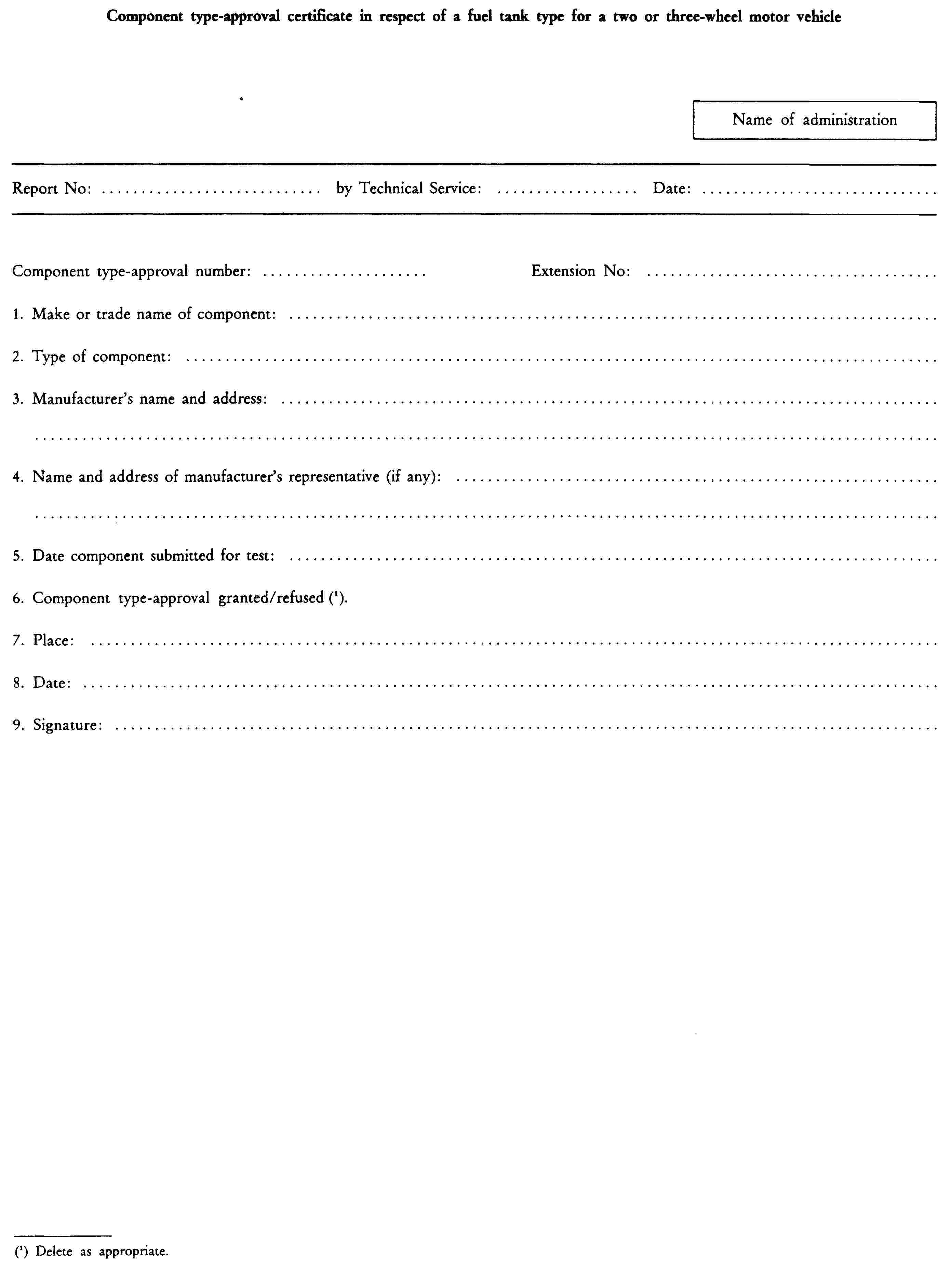
ANNEX II
REQUIREMENTS CONCERNING THE FITTING OF FUEL TANKS AND FUEL SUPPLY SYSTEMS TO TWO OR THREE-WHEEL MOTOR VEHICLES
1. FUEL TANK
Tank attachment systems must be designed, manufactured and installed in such a way as to fulfil their function whatever the driving conditions.
2. FUEL-SUPPLY SYSTEM
Engine fuel-system components must be suitably protected by a part of the frame or bodywork in such a way that they cannot strike against obstacles on the ground. That protection is not required if the components in question, when located beneath the vehicle, are further from the ground than the part of the frame or bodywork that is located immediately ahead of them.
The fuel-supply system must be designed, manufactured and installed in such a way as to withstand the effects of any internal and external corrosion to which it is exposed. No motion due to torsion, flexing and vibration of the vehicle structure, engine and transmission must subject fuel-system components to abnormal friction or stressing.
Appendix 1
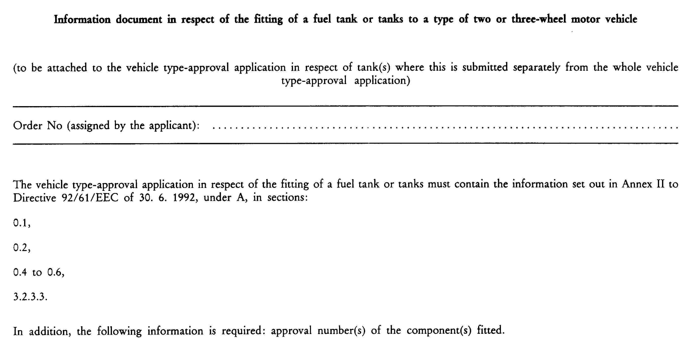
Appendix 2

CHAPTER 7
ANTI-TAMPERING MEASURES FOR TWO-WHEEL MOPEDS AND MOTORCYCLES
ANNEX
1. DEFINITIONS
or the purposes of this Chapter:
|
1.1. |
‘Anti-tampering measures for two-wheel mopeds and motorcycles’ means a series of technical requirements and specifications the aim of which is to prevent, as far as possible, unauthorized modifications which may prejudice safety, in particular by increasing vehicle performance, and damage the environment. |
|
1.2. |
‘Vehicle performance’ means the maximum speed of mopeds and the engine power of motorcycles. |
|
1.3. |
‘Vehicle categories’ means vehicles subdivided into the following categories:
|
|
1.4. |
‘Unauthorized modification’ means a modification which is not permitted by this Chapter. |
|
1.5. |
‘Interchangeability of parts’ means the interchangeability of parts which are not identical. |
|
1.6. |
‘Inlet conduit’ means the combination of the inlet passage and the intake pipe. |
|
1.7. |
‘Inlet passage’ means the passage for the intake of air within the cylinder, cylinder-head or crankcase. |
|
1.8. |
‘Intake pipe’ means a part connecting the carburettor or air-control system and the cylinder, cylinder-head or crankcase. |
|
1.9. |
‘Intake system’: means the combination of the inlet conduit and the intake silencer. |
|
1.10. |
‘Exhaust system’ means the combination of the exhaust pipe, the expansion box, the exhaust silencer and the catalytic converter (if any). |
|
1.11. |
‘Special tools’ means tools which are made available only to distributors authorized by the vehicle manufacturer and are not available to the general public. |
2. GENERAL PROVISIONS
|
2.1. |
Interchangeability of non-identical parts between component-type-approved vehicles:
|
|
►C3 2.2. |
The manufacturer must declare that modifications of the following characteristics will not increase the maximum power of a category B motorcycle by more than 10 % or ◄ increase the maximum speed of a moped by more than 5 km/h and that in no case may the maximum design speed or the maximum net engine power for the category concerned be exceeded: ignition (advance, etc.), fuel feed system. |
|
2.3. |
Category B motorcycles must comply with the requirements of either 2.3.1 or 2.3.2 or 2.3.3 and with 2.3.4 and 2.3.5.
|
|
2.4. |
Removing the air filter must not have the effect of increasing a moped's maximum design speed by more than 10 %. |
3. SPECIFIC REQUIREMENTS FOR VEHICLES IN CATEGORIES A AND B
The requirements in this section are not mandatory unless a single requirement or combination of requirements proves necessary to impede tampering resulting in the vehicle's maximum design speed increasing by more than 5 km/h in the case of category A vehicles or the vehicle's power increasing by more than 10 % in the case of category B vehicles. In no case may the maximum design speed or maximum net engine power of the relevant category be exceeded.
|
3.1. |
Cylinder-head gasket: after mounting, the maximum thickness of a cylinder-head gasket, if any, may not exceed — 1,3 mm for mopeds, and — 1,6 mm for motorcycles. |
|
3.2. |
Cylinder/crankcase gasket for two-stroke engines: the maximum thickness of any gasket between the base of the cylinder and the crankcase, if any, may not exceed 0,5 mm, after mounting. |
|
3.3. |
Piston for two-stroke engines: the piston, when in position at top dead centre, must not cover the inlet port. This requirement does not apply to those parts of the transfer port which coincide with the inlet port in the case of vehicles the engine of which is equipped with an induction system incorporating reed valve(s). |
|
3.4. |
For two-stroke engines, rotation of the piston through 180o must not increase engine performance. |
|
3.5. |
Without prejudice to the provisions of 2.3, no artificial restriction is permitted in the exhaust system. The valve guides of a four-stroke engine are not considered to be artificial restrictions. |
|
3.6. |
The part(s) of the exhaust system inside the silencer(s) which determine(s) the effective length of the exhaust pipe must be affixed to the silencer(s) or expansion box(es) in such a way that it (they) cannot be removed. |
|
3.7. |
Any component (mechanical, electrical, structural, etc.) which limits full engine load (e.g. a throttle control stop or a twist-grip stop) is forbidden. |
|
3.8. |
If a category A vehicle is equipped with electrical/electronic devices which limit its speed, the vehicle manufacturer must provide data and evidence to the test authorities to demonstrate that modification or disconnection of the device or its wiring system will not increase the moped's maximum speed by more than 10 %. Electrical/electronic devices which cut and/or inhibit spark ignition are forbidden if their operation results in an increase in fuel consumption or unburnt hydrocarbon emissions. Electrical/electronic devices which vary spark advance must be designed in such a way that the engine power, measured with the device functioning, does not differ by more than 10 % from the power measured with the device disconnected and with spark advance set for maximum road speed. The maximum road speed must be achieved with the spark advance set within ± 5 o of the value specified for the development of maximum power. |
|
3.9. |
Should an engine be equipped with a reed valve, this must be fixed with shear-bolts which prevent re-use of its support or bolts removable only using special tools. |
|
3.10. |
Requirements for the identification of a vehicle engine type
|

|
Appendix 1

Appendix 2
CHAPTER 8
ELECTROMAGNETIC COMPATIBILITY OF TWO OR THREE-WHEEL MOTOR VEHICLES AND ELECTRICAL OR ELECTRONIC SEPARATE TECHNICAL UNITS
LIST OF ANNEXES
|
ANNEX I |
Conditions applying to vehicles and to electrical or electronic separate technical units |
|
ANNEX II |
Method of measuring wide-band electromagnetic radiation from vehicles |
|
ANNEX III |
Method of measuring narrow-band electromagnetic radiation from vehicles |
|
ANNEX IV |
Methods of testing vehicle immunity to electromagnetic radiation |
|
ANNEX V |
Methods of measuring wide-band electromagnetic radiation from separate technical units (STUs) |
|
ANNEX VI |
Method of measuring narrow-band electromagnetic radiation from separate technical units (STUs) |
|
ANNEX VII |
Methods of testing the immunity of separate technical units (STUs) to electromagnetic radiation |
|
ANNEX VIII |
Models for information document (Appendix 1) and component type-approval certificate (Appendix 2) |
|
ANNEX IX |
Models for information document (Appendix 1) and component type-approval certificate (Appendix 2) of a type of separate technical unit (STU) |
ANNEX I
CONDITIONS APPLYING TO VEHICLES AND TO ELECTRICAL AND ELECTRONIC SEPARATE TECHNICAL UNITS
1. DEFINITIONS
For the purposes of this Chapter:
|
1.1. |
‘electromagnetic compatibility’ means the ability of a vehicle or one of its electrical/electronic systems to function satisfactorily in its electromagnetic environment without introducing intolerable electromagnetic disturbances to anything in that environment. Complex components and subunits (electric motors, thermostats, electronic circuit boards, etc.) which are sold direct to the end-user and are not exclusively designed for two or three-wheel motor vehicles must comply either with the provisions of this Directive or with those of Council Directive 89/336/EEC of 3 May 1989 on the approximation of the laws of the Member States relating to electromagnetic compatibility. |
|
1.2. |
‘electromagnetic disturbance’ means any electromagnetic phenomenon which may degrade the performance of a vehicle or one of its electronic/electrical systems. An electromagnetic disturbance may be electromagnetic noise, an unwanted signal or a change in the propagation medium itself. |
|
1.3. |
‘electromagnetic immunity’ means the ability of a vehicle or one of its electronic/electrical systems to perform without degradation of quality in the presence of specific electromagnetic disturbances. |
|
1.4. |
‘electromagnetic environment’ means all electromagnetic phenomena present in a given situation. |
|
1.5. |
‘reference limit’ means the nominal level to which both the component type-approval of the vehicle type and the conformity-of-production limit value refer. |
|
1.6. |
‘reference antenna’ means a balanced half-wave dipole tuned to the measured frequency. |
|
1.7. |
‘wide-band emission’ means any emission which has a bandwidth exceeding that of a specific receiver or measuring instrument. |
|
1.8. |
‘narrow-band emission’ means any emission which has a bandwidth less than that of a specific receiver or measuring instrument. |
|
1.9. |
‘electronic/electrical separate technical unit (STU)’ means the electronic and/or electrical component, or the set of components provided for installation in a vehicle, together with all electrical connections and associated wiring for the execution of several specific functions. |
|
1.10. |
‘STU’ means the test carried out on one or more specific STUs. |
|
1.11. |
‘vehicle type with regard to electromagnetic compatibility’, given that there are no fundamental differences from one vehicle to another, means inter alia:
|
|
1.12. |
‘STU type in relation to electromagnetic compatibility’ means a separate technical unit that does not differ from other units in its essential aspects, e.g.,
|
|
1.13. |
‘direct vehicle control’ the vehicle control performed by the rider acting on the steering, the brakes and the accelerator control. |
2. APPLICATION FOR COMPONENT TYPE-APPROVAL
|
2.1. |
Application for component type-approval of a vehicle type with regard to electromagnetic compatibility must be accompanied not only by the information provided for in Annex VIII (Appendix 1) but also by the following:
|
|
2.2. |
The application for component type-approval in respect of the electromagnetic compatibility of an STU type:
|
3. MARKING
|
3.1. |
All STUs, with the exception of cables other than ignition connecting cables, must bear the following:
|
|
3.2. |
these marks must be indelible and clearly legible. |
4. COMPONENT TYPE-APPROVAL OF A VEHICLE TYPE
|
4.1. |
If the vehicle submitted for testing meets the requirements of this Chapter, component type-approval must be granted and be valid for all the specific combinations set out in the list referred to in 2.1.1. |
|
4.2. |
However, the testing bodies responsible for the component type-approval tests may only waive the immunity test referred to in 5.4 in the case of vehicles fitted with electrical or electronic devices, if, in the event of the failure of such devices, the safety functions as performed by the braking, light-signalling, audible-warning and steering systems are in no way impaired. Such exemptions, with duly substantiated reasons, must be mentioned explicitly in the test report. |
|
4.3. |
Component type-approval of the vehicle The following ways of component type-approving the vehicle are available: 4.3.1. Component type-approval of a complete installation on the vehicle. A complete installation on the vehicle may be granted component type-approval directly by passing tests conducted in accordance with the limits and procedures laid down in section 5. If this route is chosen by a vehicle manufacturer no separate STU testing is required. 4.3.2. Component type-approval of vehicle type via individual STU tests. The vehicle manufacturer may obtain component type-approval for the vehicle by demonstrating to the approval authority that all of the relevant STUs (see 2.1.1) have been individually approved in accordance with this Chapter and have been installed in accordance with any conditions attached thereto. |
|
4.4. |
Component type-approval of a STU A STU may be component type-approved if it passes tests conducted in accordance with the limits and procedures laid down in section 5. Approval may be granted for fitting to any vehicle type or to a specific vehicle type or types as requested by the manufacturer. |
5. REQUIREMENTS
5.1. General requirements
All vehicles and STUs must be designed and constructed in such a way that, under normal conditions of use, they meet the conditions laid down in this Chapter.
However, the measuring methods used in checking the immunity of vehicles and STUs to electromagnetic radiation described in Annexes IV and VII respectively are not required until three years after the date of entry into force of this Chapter.
5.2. Requirements relating to wide-band radiation from vehicles
5.2.1. Measuring method
The electromagnetic radiation generated by the vehicle type submitted for testing are to be measured by the method described in Annex II.
5.2.2. Vehicle reference limits (wide-band)
|
5.2.2.1. |
If measurements are taken using the method described in Annex II, in respect of a vehicle-antenna distance of 10,0 ± 0,2 m, the radiation reference limit will be 34 dB microvolts/m (50 microvolts/m) in the 30-75 MHz frequency band and 34-45 dB microvolts/m (50-180 microvolts/m) in the 75-400 MHz frequency band. As shown in Appendix 1 to this Annex, this limit will increase by the frequency logarithm for frequencies above 75 MHz. In the 400-1 000 MHz frequency band the limit remains constant at 45 dB (180 microvolts/m). |
|
5.2.2.2. |
If measurements are taken using the method described in Annex II, in respect of a vehicle-antenna distance of 3,0 ± 0,5 m, the radiation reference limits will be 44 dB microvolts/m (160 microvolts/m) in the 30-75 MHz frequency band and 44-55 dB (160-546 microvolts/m) in the 75-400 MHZ frequency band. As shown in Appendix 2 to this Annex, this limit will increase by the frequency logarithm for frequencies above 75 MHz. In the 400-1 000 MHz frequency band the limit remains constant at 55 dB (546 microvolts/m). |
|
5.2.2.3. |
The measured values expressed in dB (microvolts/m) must be at least 2,0 dB below the reference limit for the vehicle submitted for testing. |
5.3. Requirements relating to narrow-band radiation emissions from vehicles
5.3.1. Measuring method
The electromagnetic radiation from the vehicle submitted for testing is to be measured by the method described in Annex III.
5.3.2. Vehicle Reference limits for vehicle narrow-band radiation
|
5.3.2.1. |
If measurements are taken using the method described in Annex III, in respect of a vehicle-antenna distance of 10,0 ± 0,2 m, the radiation reference limit will be 24 dB (16 microvolts/m) in the 30-75 MHz frequency band and 24-35 dB (16-56 microvolts/m) in the 75-400 MHz frequency band. As shown in Appendix 3 to this Annex, this limit will increase by the frequency logarithm for frequencies above 75 MHz. In the 400-1 000 MHz frequency band the limit remains constant at 35 dB (56 microvolts/m). |
|
5.3.2.2. |
If measurements are taken using the method described in Annex III, in respect of a vehicle-antenna distance of 3,0 ± 0,05 m, the radiation reference limits will be 34 dB (50 microvolts/m) in the 30-75 MHz frequency band and 34-45 dB (50-180 microvolts/m) in the 75-400 MHz frequency band. As shown in Appendix 4 to this Annex, this limit will increase by the frequency logarithm for frequencies above 75 MHz. In the 400-1 000 MHz frequency band the limit remains constant at 45 dB (microvolts/m). |
|
5.3.2.3. |
The measured values for the vehicle type submitted for testing expressed in dB (microvolts/m), must be at least 2,0 dB below the reference limit. |
5.4. Requirements regarding vehicle immunity to electromagnetic radiation
5.4.1. Measuring method
Tests to determine the immunity of the vehicle type to electromagnetic radiation must be conducted in accordance with the method described in Annex IV.
5.4.2. Vehicle immunity reference limits
|
5.4.2.1. |
If measurements are taken using the method described in Annex IV, the field strength reference level must be 24 volts/m r.m.s. in over 90 % of the 20 MHz to 1 000 MHz frequency band and 20 volts/m r.m.s. over the whole 20 MHz to 1 000 MHz frequency band. |
|
5.4.2.2. |
The vehicle representative of the type submitted for testing must not display any deterioration in the direct control of the vehicle which might be observed by the driver or by any other road user when the vehicle in question is in the state defined in Annex IV, section 4, and when it is subjected to the field strength expressed in volts/m, which must be 25 % above the reference level. |
5.5. Requirements concerning wide-band STU radiation
5.5.1. Measuring method
The electromagnetic radiation generated by the STU submitted for component type-approval must be measured by the method described in Annex V.
5.5.2. STU wide-band reference limits
|
5.5.2.1. |
If measurements are taken using the method described in Annex V, the radiation reference limit will be 64-54 dB (microvolts/m) within the 30-75 MHz frequency band, this limit decreasing by the frequency logarithm, and 54-65 dB microvolts/m) in the 75-400 MHz band, this limit increasing by the frequency logarithm, as shown in Appendix 5 to this Annex. In the 400-1 000 MHz frequency band the limit remains constant at 65 dB (1 800 microvolts/m). |
|
5.5.2.2. |
The measured values for the STU submitted for approval, expressed in dB (microvolts/m), must be at least 2,0 dB below the reference limits. |
5.6. Requirements concerning narrow-band STU radiation
5.6.1. Method of measurement
The electromagnetic radiation generated by the STU submitted for component type-approval is to be measured in accordance with the method described in Annex VI.
5.6.2. STU narrow-band reference limits
|
5.6.2.1. |
If measurements are taken using the method described in Annex VI, the radiation reference limit will be 54-44 dB (microvolts/m) in the 30-75 MHz frequency band, this limit decreasing by the fequency logartihm, and 44-55 dB (microvolts/m) in the 75-400 MHz band, this limit increasing by the frequency logarithm, as shown in Appendix 6 to this Annex. In the 400-1 000 MHz frequency band the limit remains constant at 55 dB (560 microvolts/m). |
|
5.6.2.2. |
The measured values for the STU submitted for competent type-approval, expressed in dB (microvolts/m), must be at least 2,0 dB below the reference limits. |
5.7. Requirements concerning STU immunity to electromagnetic radiation
5.7.1. Method of measurement
The immunity to electromagnetic radiation of the STU submitted for component type-approval will be tested by means of one of the methods described in Annex VII.
5.7.2. STU immunity reference limits
|
5.7.2.1. |
If measurements are taken using the methods described in Annex VII, the immunity test reference levels will be 48 volts/m for the 150 mm stripline testing method, 12 volts/m for the 800 mm stripline testing method, 60 volts/m for the TEM cell testing method, 48 mA for the Bulk Current Injection (BCI) testing method and 24 volts/m for the Free Field testing method. |
|
5.7.2.2. |
The STUs representative of the type submitted for testing may not exhibit any malfunction which is able to cause any degradation on the direct control of the vehicle perceptible to the driver or other road user if the vehicle is in the state defined in Annex IV, section 4, at a field strength or current expressed in appropriate linear units 25 % above the reference limit. |
6. CONFORMITY OF PRODUCTION
|
6.1. |
Measures to ensure the conformity of production must be taken in accordance with the provisions laid down in Article 4 of Directive 92/61/EEC. |
|
6.2. |
Conformity of production with regard to the electromagnetic compatibility of the vehicle or component or separate technical unit is to be checked on the basis of the data contained in the type-approval certificate(s) set out in Annex VIII and/or IX to this Directive as appropriate. |
|
6.3. |
If the authority is not satisfied with the auditing procedure of the manufacturer, then sections 1.2.2 and 1.2.3 of Annex VI to Directive 92/61/EEC and sections 6.3.1 and 6.3.2 below apply.
|
7. EXCEPTIONS
|
7.1. |
Vehicles with compression ignition engines are deemed to comply with the requirements laid down in 5.2.2. |
|
7.2. |
Vehicles or electrical/electronic STUs not incorporationg an electronic oscillator with an operating frequency of more than 9 kHz ar deemed to comply with the requirements laid down in 5.3.2 and in Annex III. |
|
7.3. |
Vehicles not fitted with any sensitive electronic device are exempted from the tests set out in Annex IV. |
|
7.4. |
It is not considered necessary to carry out any immunity test on STUs the functions of which are not considered essential for the direct control of the vehicle. |
Appendix 1

Frequency — megahertz — logarithmic
(see section 5.2.2.1)
Appendix 2
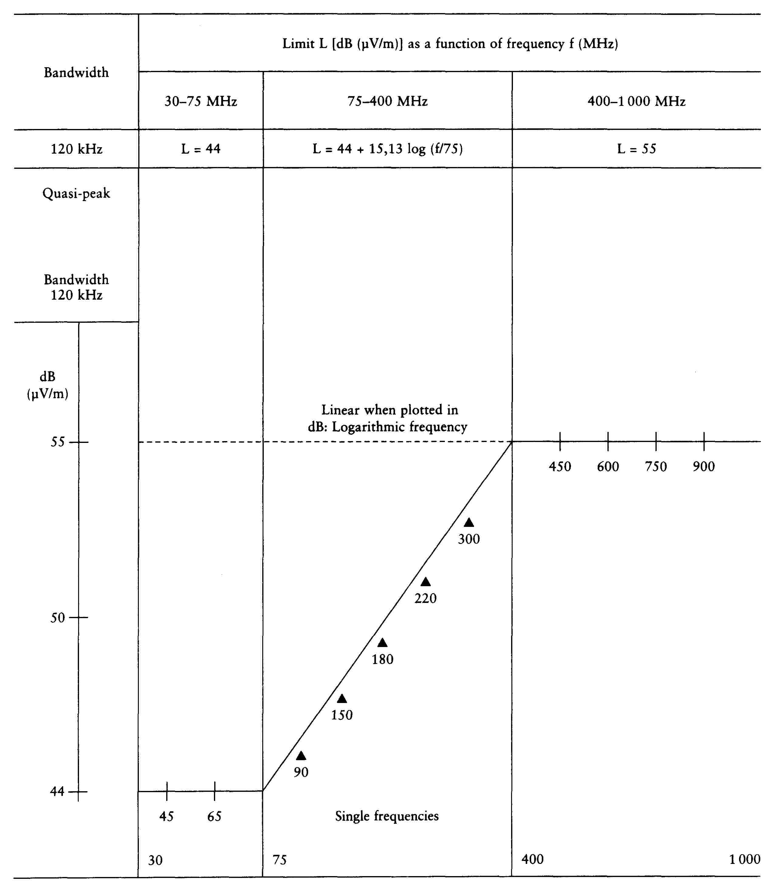
Frequency — megahertz — logarithmic
(see section 5.2.2.2)
Appendix 3
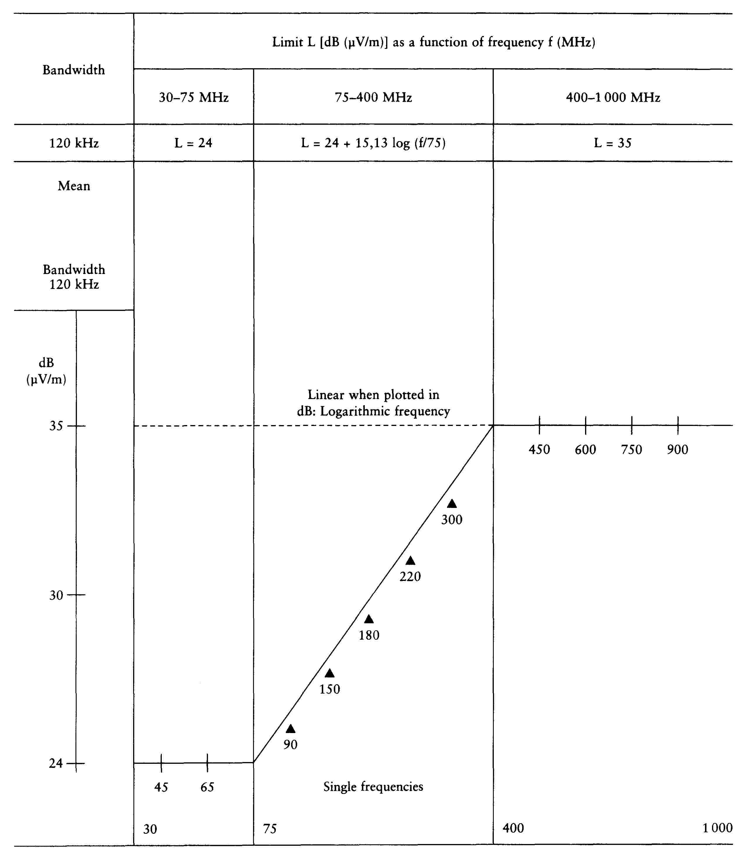
Frequency — megahertz — logarithmic
(see section 5.3.2.1)
Appendix 4

Frequency — megahertz — logarithmic
(see section 5.3.2.2)
Appendix 5
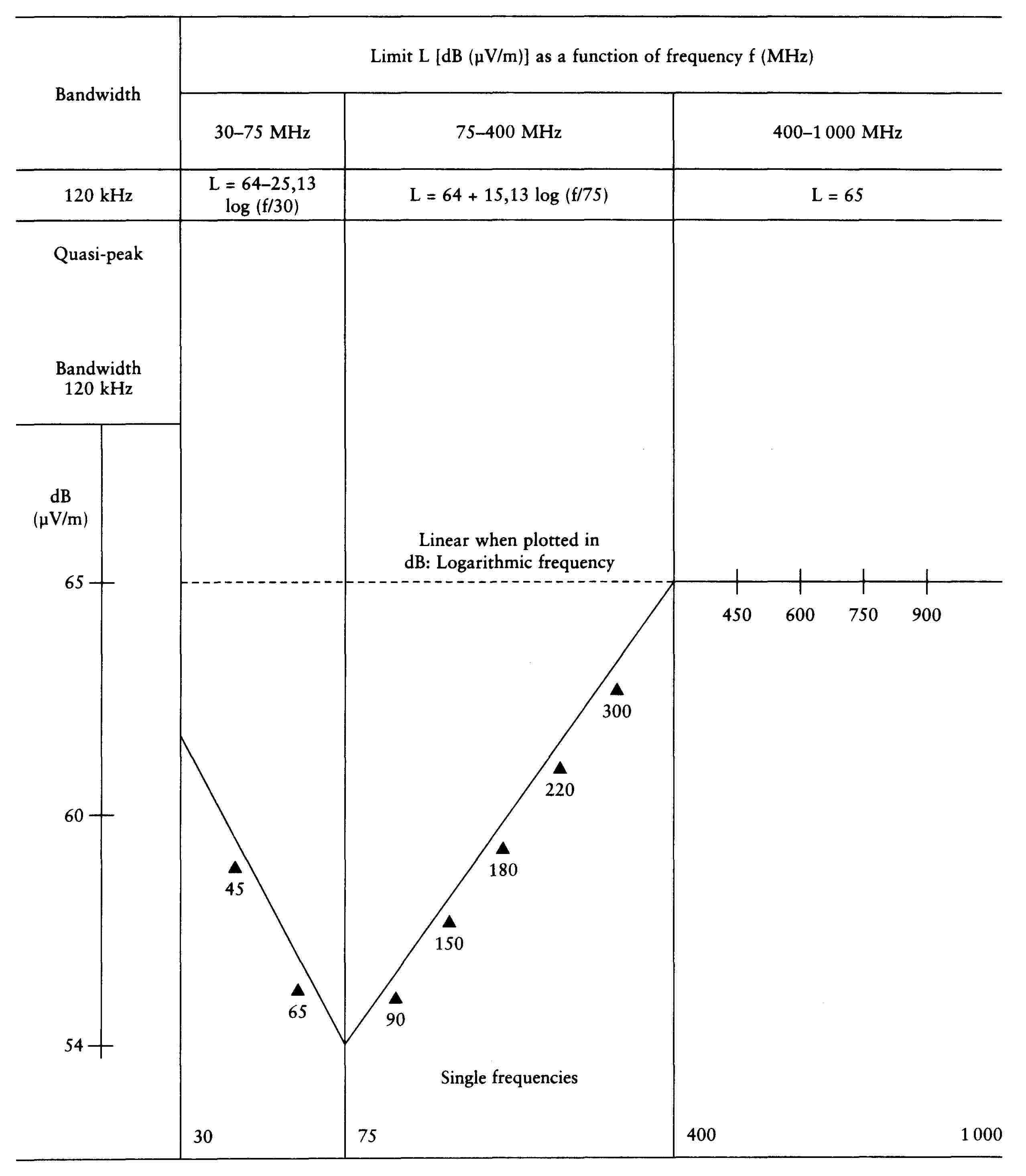
Frequency — megahertz — logarithmic
(see section 5.5.2.1)
Appendix 6

Frequency — megahertz — logarithmic
(see section 5.6.2.1)
ANNEX II
METHOD OF MEASURING WIDE-BAND ELECTROMAGNETIC RADIATION FROM VEHICLES
1. GENERAL
1.1. Measuring equipment
The measuring equipment must meet the conditions laid down in Publication No 16, Edition 2, of the International Special Committee on Radio Interference (CISPR).
A quasi-peak detector must be used to measure wide-band electromagnetic radiation.
1.2. Test method
The test is designed to measure wide-band radiation from spark ignition systems and electric motors within systems designed for continuous use (e.g., electric traction motors, heating system/demister motors and fuel pumps).
As regards the choice of reference antenna, that choice being determined by common agreement between manufacturers and testing bodies: the distance in the vehicle may be either 10 or 3 metres. In both cases, the conditions set out in section 3 below must be complied with.
2. EXPRESSION OF RESULTS
The measured results are expressed in dB (microvolts/m) for bandwidths of 120 kHz. If the measuring equipment's actual bandwidth B (expressed in kHz) does not correspond exactly to 120 kHz, readings must be converted to a bandwidth of 120 kHz by adding 20 log (120/B), where B must be less than 120 kHz.
3. TEST CONDITIONS
|
3.1. |
The test surface must be horizontal and untrammelled and free of electromagnetic reflective surfaces within a minimum radius of 30 m, measured from a point mid-way between the vehicle and the antenna (see fig. 1 in Appendix 1). Alternatively, the test surface may be any location that fulfils the conditions shown in fig. 2 in Appendix 1. |
|
3.2. |
Both the measuring equipment and the test cab or the vehicle in which the measuring equipment is situated are positioned within the part of the test surface shown in fig. 1 in Appendix 1. Where the test surface fulfils the conditions stated in fig. 2 in Appendix 1, the measuring equipment must lie outside the part shown in fig. 2. |
|
3.3. |
Closed installations may be used for the tests, if it is to be demonstrated that a correlation exists between these installations and the external test surface. Such installations are not subject to the dimensional conditions specified in figs 1 and 2 of Appendix 1, except for the condition relating to the distance between the vehicle and the antenna and to the height of the latter. |
|
3.4. |
In order to ensure the absence of any noise or extraneous signals of a level that might materially affect the measurements, such measurements must be taken before and after the main test. If the vehicle is present during these measurements, steps must be taken to ensure that no emission from the vehicle can significantly affect the measurements (e.g., the ignition key should be removed or the battery disconnected when the vehicle is withdrawn from the test surface). For both types of measurement, the noise or extraneous signal must be at least 10 dB below the limits stated in Annex I (5.2.2.1 or 5.2.2.2, as the case may be), save for intentional narrow-band ambient emissions. |
4. STATE OF THE VEHICLE DURING THE TEST
4.1. Engine
The engine must function at its normal operating temperature and, where a gearbox is fitted, must be in neutral. If this is not possible for practical reasons, alternative solutions must be sought by agreement with the manufacturer and the authorities responsible for carrying out the tests. Steps must be taken to ensure that the gear-changing mechanisms do not exert any influence on electromagnetic radiation from the vehicle. During each measurement, the engine must operate as follows:
|
Engine type |
Measurement methods |
|
Spark ignition |
Quasi-peak |
|
One cylinder |
2 500 rpm ± 10 % |
|
More than one cylinder |
1 500 rpm ± 10 % |
|
Electric motors |
3/4 of the maximum operating power declared by the manufacturer |
4.2. Equipment controlled by the driver
The equipment controlled by the driver (including such components as heating-fan and air-conditioning motors and excluding other components such as seat or windscreen-wiper motors) is designed for steady-state operation cycle at 100 % and must operate in such a way as to absorb the maximum current.
|
4.3. |
Test must not be carried out in the rain, nor must they be carried out for 10 minutes after it has stopped raining. |
|
4.4. |
The driver must occupy the driving position assigned to him if, in the judgment of the testing body, this represents the worst-case scenario. |
5. ANTENNA TYPE, POSITION AND ORIENTATION
5.1. Antenna type
Any type of linearly polarized antenna is permitted, provided that it can be standardized on the reference antenna.
5.2. Measurement height and distance
5.2.1. Height
|
5.2.1.1. |
Tests at 10 m The antenna phase mid-point must be 3,0 ± 0,05 m above the vehicle plane. |
|
5.2.1.2. |
Tests at 3 m The antenna phase mid-point must be 1,8 ± 0,05 m above the vehicle plane. |
|
5.2.1.3. |
No part of the antenna receiving components must be less than 0,25 m from the vehicle plane. |
5.2.2. Measuring distance
|
5.2.2.1. |
Tests at 10 m The horizontal distance from the antenna phase mid-point to the external surface of the vehicle must be 10,0 ± 0,2 m. |
|
5.2.2.2. |
Tests at 3 m The horizontal distance from the antenna phase mid-point to the external surface of the vehicle must be 3,0 ± 0,05 m. |
|
5.2.2.3. |
If the test is carried out in a closed installation with the object of creating an electromagnetic screen against radiofrequencies, the position of the antenna receiving components must not be less than (0,5) m from any type of radiofrequency absorption material of less than (1,5) m from the closed installation. There must be no absorption material between the receiving antenna and the vehicle under test. |
5.3. Position of the antenna in relation to the vehicle
The antenna must be positioned successively on each side of the vehicle parallel to the longitudinal median plane of the vehicle and in line with the mid-point of the engine (see fig. 3 in Appendix 1).
5.4. Position of the antenna
Readings are taken for each measuring point, first with the antenna vertically polarized and then horizontally polarized (see fig. 3 in Appendix 1).
5.5. Measurements
The maximum value of the four measurements taken in accordance with 5.3 and 5.4 for each frequency is regarded as the characteristic measurement for this frequency.
6. FREQUENCIES
6.1. Measurement
Measurements are taken over a range of frequencies from 30 to 1 000 MHz. A vehicle is deemed to comply with the requisite limits over the entire frequency range if it meets the limits laid down for the following 11 frequencies: 45, 65, 90, 150, 180, 220, 300, 450, 600, 750 and 900 MHz. Should the limit be exceeded during the tests, steps must be taken to confirm that this is due to the vehicle and not to ambient radiation.
6.2. Tolerances
|
Single frequency (MHz) |
Tolerance (MHz) |
|
45, 65, 90, 150, 180 and 220 |
± 5 |
|
300, 450, 600, 750 and 900 |
± 20 |
The tolerances are applied to the above frequencies with the aim of avoiding interference in transmissions operating at, or close to, the nominal frequencies during the measurements.
Appendix 1
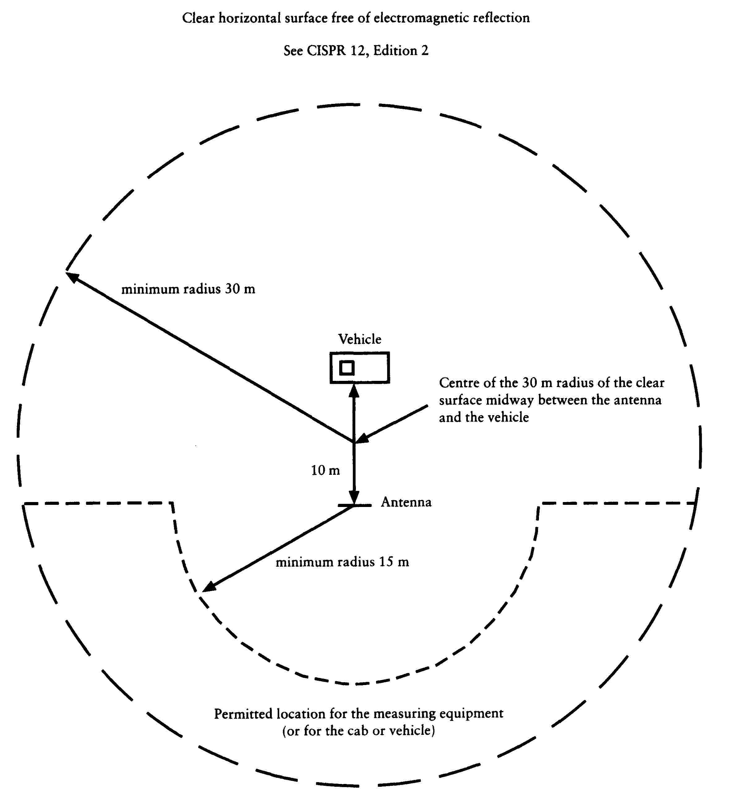
Figure 1
Vehicle test surface
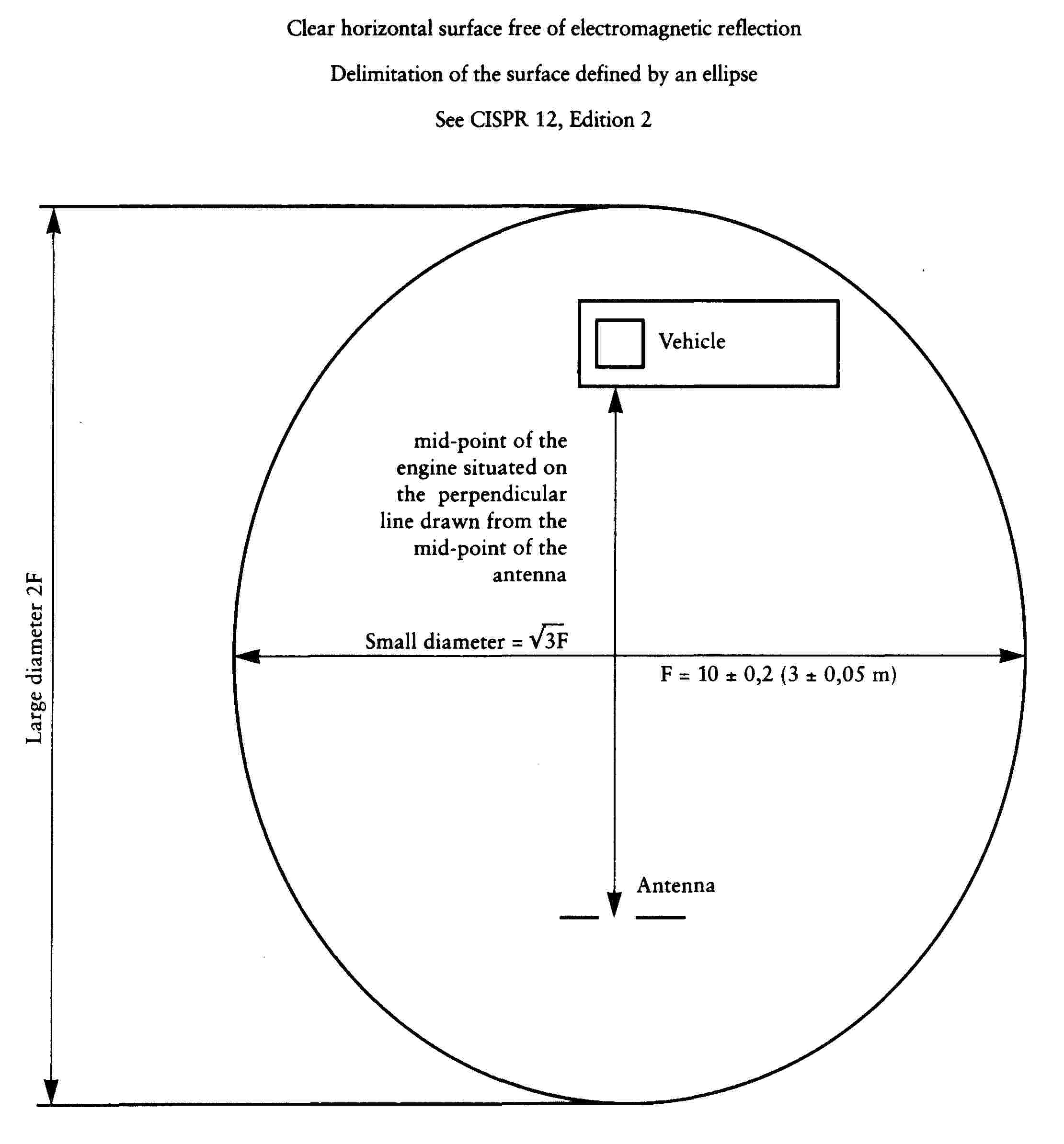
Figure 2
Vehicle test surface
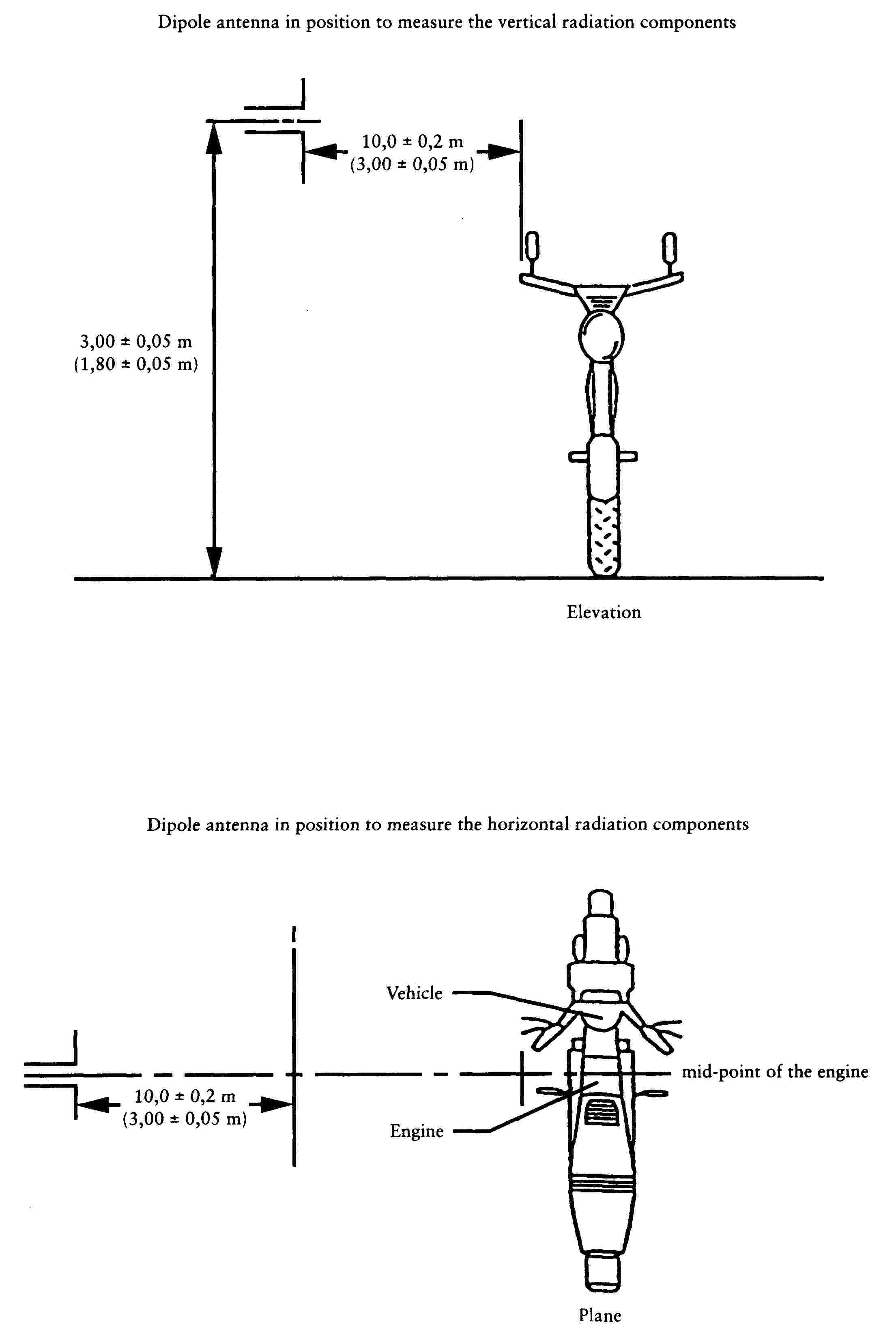
Figure 3
Position of antenna in relation to vehicle
ANNEX III
METHOD OF MEASURING NARROW-BAND ELECTROMAGNETIC RADIATION FROM VEHICLES
1. GENERAL
1.1. Measuring equipment
The measuring equipment must comply with the conditions laid down in Publication No 16, Edition 2, of the International Special Committee on Radio Interference (CISPR).
A mean-value detector is used to measure narrow-band electromagnetic radiation.
1.2. Test method
The test is designed to measure narrow-band electromagnetic radiation such as that which may be generated by a microprocessor-based system or from another narrow band source.
As regards the choice of antenna, that choice being determined by common agreement between manufacturer and testing body, the distance from the vehicle may be either 10 or 3 metres. In both cases, the conditions set out in section 3 below must be complied with. In the initial stage (2-3 minutes) it is possible, through the choice of antenna position and polarization, to scan the range of frequencies listed in 6.1 by the use of a spectrum analyzer or an automatic receiver to indicate the maximum transmitting frequencies. This can be useful for selecting the frequencies to be tested in each band (see section 6).
2. EXPRESSION OF THE RESULTS
The measured results are expressed in dB (microvolts/m).
3. TEST CONDITIONS
|
3.1. |
The test surface must be horizontal and untrammelled and free of electromagnetic reflections within a minimum radius of 30 m, measured from a point mid-way between the vehicle and the antenna (see fig. 1 in Appendix 1, Annex II). Alternatively, the test surface may be any location that fulfils the conditions shown in fig. 2 in Appendix 1, Annex II. |
|
3.2. |
Both the measuring equipment and the test cab or the vehicle in which the measuring equipment is situated are positioned within the test surface, but only in the part shown in fig. 1 in Appendix 1, Annex II. Where the test surface fulfils all the conditions set out in fig. 2 in Appendix 1, Annex II, the measuring equipment must lie outside the part shown in that figure. |
|
3.3. |
Closed installations may be used for the tests, provided that it can be demonstrated that a correlation exists between these installations and the external test surface. Such installations are not subject to the dimensional conditions laid down in figs 1 and 2 in Appendix 1, Annex II, except as regards the distance between the vehicle and the antenna and to the height of the latter. |
|
3.4. |
In order to ensure the absence of any noise or extraneous signals of a level that might materially affect the measurements, such measurements must be taken before and after the main test. Steps must be taken to ensure that no emission from the vehicle can significantly affect the measurements (e.g., the ignition key should be removed or the battery/batteries disconnected when the vehicle is withdrawn from the test surface). For both types of measurement, the noise or extraneous signal must be at least 10 dB below the interference limits contained in Annex I (5.3.2.1 or. 5.3.2.2, depending on the distance between the vehicle and the antenna), save for intentional narrow-band ambient emissions. |
4. STATE OF THE VEHICLE DURING THE TESTS
|
4.1. |
The vehicle's electronic systems must be in their normal operating mode and the vehicle must be stationary. |
|
4.2. |
The ignition must be connected. The engine must not be running. |
|
4.3. |
Tests must not be carried out in the rain, nor must they be carried out for 10 minutes after it has stopped raining. |
5. ANTENNA TYPE, POSITION AND ORIENTATION
5.1. Antenna type
Any type of linearly polarized antenna is permitted, provided that it can be standardized with the reference antenna.
5.2. Measurement height and distance
5.2.1. Height
|
5.2.1.1. |
Tests at 10 m The antenna phase mid-point must be 3,0 ± 0,05 m above the vehicle plane. |
|
5.2.1.2. |
Tests at 3 m The antenna phase mid-point must be 1,8 ± 0,05 m above the vehicle plane. |
|
5.2.1.3. |
No part of the antenna's receiving components may be less than 0,25 m from the vehicle plane. |
5.2.2. Measuring distance
|
5.2.2.1. |
Test at 10 m The horizontal distance from the antenna phase mid-point to the external surface of the vehicle must be 10,0 ± 0,2 m. |
|
5.2.2.2. |
Test at 3 m The horizontal distance from the antenna phase mid-point to the external surface of the vehicle must be 3,00 ± 0,05 m. |
|
5.2.2.3. |
If the test is carried out in a closed installation with the object of creating an electromagnetic screen against radio frequencies, the position of the antenna receiving components must not be less than (0,5) m from any type of radiofrequency absorption material or less than (1,5) m from the wall of the installation in question. There must be no absorption material between the receiving antenna and the vehicle under test. |
5.3. Position of the antenna in relation to the vehicle
The antenna must be positioned successively on each side of the vehicle parallel to the median longitudinal plane of the vehicle and in line with the mid-point of the engine (see figs 1, 2 and 3, Appendix 1, Annex II).
5.4. Position of the antenna
Readings are taken for each measuring point, with the antenna both vertically and horizontally polarized (see fig. 3, Appendix 1, Annex II).
5.5. Measurements
The maximum values of the four measurements taken for each frequency in accordance with 5.3 and 5.4 are regarded as the characteristic measurement for this frequency.
6. FREQUENCIES
6.1. Measurements
Measurements are taken over a range of frequencies from 30 to 1 000 MHz. This range is divided into 11 bands. In each band a test is carried out on the frequency with the highest value in order to check that it is within the required limits. A vehicle is deemed to comply with the requisite limits over the entire frequency range if it meets with the selected frequency in each of the following 11 frequency bands: 30-45, 45-80, 80-130, 130-170, 170-225, 225-300, 300-400, 400-525, 525-700, 700-850 and 850-1 000 MHz.
|
6.2. |
If, during the first test carried out in accordance with the test method described in 1.2, the narrow-band radiation for any of the bands defined in 6.1 are at least 10 dB below the reference limit, then the vehicle is deemed to fulfil the conditions laid down in this Annex for the frequency band under consideration. In that case, the full test is not necessary. |
ANNEX IV
METHODS OF TESTING VEHICLE IMMUNITY TO ELECTROMAGNETIC RADIATION
1. GENERAL
1.1. Test methods
These tests are designed to demonstrate the insensitivity of the vehicle to any factor which may alter the quality of its direct control. The vehicle must be exposed to the electromagnetic fields, described in this Annex, and must be monitored during the tests.
2. EXPRESSION OF THE RESULTS
The field strengths must be expressed in volts/m for all the tests described in this Annex.
3. TEST CONDITIONS
The test equipment must be capable of generating the field strengths in the range of frequencies defined in this Annex, and must meet the (national) legal requirements regarding electromagnetic signal. The control and monitoring equipment must not be susceptible to radiation fields whereby the tests could be invalidated.
4. STATE OF THE VEHICLE DURING THE TESTS
|
4.1. |
The mass of the vehicle must be equal to the mass in running order.
|
|
4.2. |
Where STUs are involved in the direct control of the vehicle and where these systems do not operate under the conditions described in 4.1.1, the testing authority may carry out separate tests on the systems in question under conditions agreed with the vehicle manufacturer. |
|
4.3. |
During the tests on the vehicle, only non-interference-generating equipment may be used (see section 8). |
|
4.4. |
Under normal conditions, the vehicle must be facing the antenna. |
5. TYPE, POSITION AND ORIENTATION OF THE FIELD GENERATOR
5.1. Type of field generator
|
5.1.1. |
The criterion for the selection of the field generator type is the capacity of the latter to attain the prescribed field strength at the reference point (see 5.4) and at the appropriate frequencies. |
|
5.1.2. |
Either the antenna(s) or a transmission line system (TLS) may be used as the field-generating device(s). |
|
5.1.3. |
The design and orientation of the field generator must be such that the field is polarized both horizontally and vertically at frequencies between 20 and 1 000 MHz. |
5.2. Measurement height and distance
5.2.1. Height
|
5.2.1.1. |
The phase mid-point of all antennas must not be less than 1,5 m above the vehicle plane. |
|
5.2.1.2. |
No part of the antenna radiator elements must be less than 0,25 m from the vehicle plane. |
5.2.2. Measuring distance
|
5.2.2.1. |
Greater homogeneity of the field may be obtained by placing the field generator as far as technically possible from the vehicle. This distance will normally be in the range 1 to 5 m. |
|
5.2.2.2. |
If the test is carried out in a closed installation, the radiator elements of the field generator must not be less than 0,5 m from any type of radiofrequency absorption material and not less than 1,5 m from the wall of the installation in question. There must be no absorption material between the transmitting antenna and the vehicle under test. |
5.3. Position of the antenna in relation to the vehicle
|
5.3.1. |
The field generator must be positioned in the median longitudinal plane of the vehicle. |
|
5.3.2. |
No part of the TLS, except the vehicle plane, may be less than 0,5 m from any part of the vehicle. |
|
5.3.3. |
Any field generator placed above the vehicle must cover at least 75 % of the length of the vehicle. |
5.4. Reference point
|
5.4.1. |
The reference point is the point at which the field strengths are established and is defined as follows:
|
|
5.5. |
If the testing authority chooses to subject the rear part of the vehicle to radiation, the reference point must be established as stated in 5.4. In this case the vehicle will be positioned with its front part facing in the opposite direction to the antenna and as if it had been rotated horizontally through 180 degrees about its central point. The distance between the antenna and the nearest part of the outer surface of the vehicle must remain the same (see Appendix 3). |
6. REQUISITE TEST CONDITIONS
6.1. Range of frequencies, duration of the tests, polarization
The vehicle must be exposed to electromagnetic radiation in the 20-1 000 MHz frequency range.
|
6.1.1. |
The tests are to be carried out at the following 12 frequencies: 27, 45, 65, 90, 150, 180, 220, 300, 450, 600, 750 and 900 MHz ± 10 % for 2 s at ± 10 % in each frequency. |
|
6.1.2. |
One of the polarization modes described in 5.1.3 must be selected by common agreement between manufacturer and testing body. |
|
6.1.3. |
All other test parameters are as defined in this Annex. |
6.2. Tests to check deterioration in direct control
|
6.2.1. |
A vehicle is deemed to fulfil the requisite immunity conditions if, during the tests carried out in the manner required by this Annex, there are no abnormal changes in the speed of the vehicle's drive wheels, there are no signs of operational deterioration which might mislead other road users and there are no other noticeable phenomena which could result in a deterioration in the direct control of the vehicle. |
|
6.2.2. |
For vehicle observation purposes, only the monitoring equipment described in section 8 may be used. |
|
6.2.3. |
If a vehicle does not meet the requirements of the tests defined in 6.2, steps must be taken to verify that the faults occurred under normal conditions and are not attributable to spurious fields. |
7. GENERATION OF THE REQUISITE FIELD STRENGTH
7.1. Test method
|
7.1.1. |
The ‘substitution method’ is to be used for the purpose of creating the field test conditions. |
|
7.1.2. |
Substitution method For each test frequency required, the RF power level of the field generator must be set so as to produce the required test field strength at the reference point of the test area without the vehicle being present. This RF power level, as well as all other relevant settings on the field generator must be recorded in the test report (calibration curve). The recorded information is to be used for type-approval purposes. Should any alterations be made to the equipment at the test location, the substitution method must be repeated. |
|
7.1.3. |
The vehicle is then brought to the test installation and positioned in accordance with the conditions laid down in section 5. The power required by 7.1.2 is then applied to the field generator for each of the frequencies indicated in 6.1.1. |
|
7.1.4. |
Whatever field-definition parameter in chosen in accordance with the conditions laid down in 7.1.2, the same parameter must be used in order to determine the strength of that field throughout the test. |
|
7.1.5. |
For the purposes of this test, the same field generating equipment and the same equipment configuration must be used as in the operations conducted in pursuance of 7.1.2. |
|
7.1.6. |
Field strength measuring device Under the substitution method, the device used to determine the field strength during the calibration stage should take the form either of a compact isotropic probe for measuring field strength or of a calibrated receiving antenna. |
|
7.1.7. |
During the calibration phase of the substitution method, the phase mid-point of the field-strength measuring device must coincide with the reference point. |
|
7.1.8. |
If a calibrated receiving antenna is used as the field strength measuring device, readings will be obtained in three directions at right angles to each other. The equivalent isotropic value corresponding to these measurements is to be regarded as the field strength. |
|
7.1.9. |
In order to take account of differences in vehicle geometry, a number of reference points must be established for the relevant test installation. |
7.2. Field strength contour
|
7.2.1. |
During the calibration phase (before the vehicle is positioned on the test surface) the field strength must not be less than 50 % of the nominal field strength at the following locations: (i) for all field-generating devices, 1,0 ± 0,02 m on either side of the reference point on a line passing through this point, and perpendicular to the median longitudinal plane of the vehicle; (ii) in the case of a TLS, 1,5 ± 0,02 m on a line passing through the reference point, and situated in the median longitudinal plane of the vehicle. |
7.3. Characteristics of the test signal to be generated
7.3.1. Peak value of the modulated test field strength
The peak value of the modulated test field strength must correspond to that of the unmodulated test field strength, the actual value in volts/m of which is defined in section 5.4.2 of Annex I.
7.3.2. Test signal waveform
The test signal must be a radio-frequency sinusoidal wave, amplitude-modulated by a sinusoidal 1 kHz wave at a modulation rate m of 0,8 ± 0,04 m.
7.3.3. Modulation rate
The modulation rate m is defined as follows:
![]()
The envelope describes the curve formed by the edges of the modulated carrier as seen on an oscillograph.
8. INSPECTION AND MONITORING EQUIPMENT
|
8.1. |
For the purposes of monitoring the external part of the vehicle and the passenger compartment and of determining whether the conditions laid down in 6.2 have been met, use will be made of a video camera or cameras. |
Appendix 1

Appendix 2

Appendix 3

ANNEX V
METHOD OF MEASURING WIDE-BAND ELECTROMAGNETIC RADIATION FROM SEPARATE TECHNICAL UNITS (STU)
1. GENERAL
1.1. Measuring equipment
The measuring equipment must meet the conditions laid down in Publication No 16, Edition 2, of the International Special Committee on Radio Interference (CISPR).
A quasi-peak detector must be used to measure wide-band electromagnetic emissions.
1.2. Test method
This test is designed to measure wide-band emissions generated by spark-ignition systems or by electric motors fitted to systems designed for continuous use (e.g. electric traction motor, heating system/demister motors, fuel pumps etc.)
2. EXPRESSION OF RESULTS
The measured results are expressed in dB (microvolts/m) for a bandwidth of 120 kHz. If the measuring equipment's actual bandwidth B (expressed in kHz) does not correspond exactly to 120 kHz, readings must be converted to a bandwidth of 120 kHz by adding 20 log (120/B), where B must be less than 120 kHz.
3. TEST CONDITIONS
|
3.1. |
The testing surface must meet the conditions laid down in publication No 16, Edition 2, of the International Special Committee en Radio Interference (CISPR). (See fig. 1 in Appendix 1 to this Annex.) |
|
3.2. |
The measuring equipment and the test cab or the vehicle in which the measuring equipment is situated must be positioned outside the area shown in fig. 1, Appendix 1 to this Annex. |
|
3.3. |
Covered equipment may be used for the tests if it is demonstrated that there is a correlation between the results obtained therewith and those obtained by using an outside surface which has been approved for the tests. Covered test equipment has the advantage of enabling tests to be conducted in all weathers, within a controlled environment and with improved measurement repeatability deriving from more stable electrical characteristics. This covered facility does not need to meet the dimensional requirements set out in figure 1, in Appendix 1 to this Annex, apart from those relating to the distance between the antenna and the STU and to the height of the antenna. |
|
3.4. |
In order to ensure that there is no extraneous noise or signal of such a magnitude that they could materially affect the measurements, the background radiation is measured before and after the main test. For both of these measurements both the noises and extraneous signals must be at least 10 dB below the limits set out in section 5.5.2.1 in Annex I, except in the case of deliberate narrow-band transmissions within the environment. |
4. STATE OF THE STU DURING THE TEST
|
4.1. |
The STU must be in its normal operating state. |
|
4.2. |
Measurements must not be carried out in the rain, nor for 10 minutes after the rain has stopped. |
|
4.3. |
The STU and its cable harnesses must be placed on insulated supports 50 + 10/- 0 mm above the earth plate. However, if one of the parts of the STU was intended to be electrically connected to the metal bodywork of the vehicle, that part must be situated on the earth plate and connected thereto electrically. The earth plate must be a metal sheet at least 0,25 mm thick. The minimum dimensions of the earth plate depends upon the size of the STU but will have to be sufficiently large to receive the cable harness and the components of the vehicle system. The earth plate must be connected to the earth conductor, located 1,0 ± 0,1 m above the ground and run parallel thereto. The STU must be ready to operate and be connected in accordance with the conditions laid down. The power distribution cable harness must run parallel to the edges of the earth plate and be no more than 100 mm form the edge of the plate closest to the antenna. The STU must be earthed in accordance with the manufacturer's specifications: no additional earth connections are permitted. The minimum distance between the STU and all of the other conducting structures such as the walls of a protected area (except, however, for the base plate below the test piece) must be at least 1,0 m. |
|
4.4. |
Power for the STU is supplied by a 50μH Line Impedance Stabilizing Network (LISN) which is connected electrically to the earth plate. The power supply voltage must be maintained at ± 10 % of the nominal operating voltage of the system. All ripple voltage must be less than 1,5 % of the nominal operating voltage of the system measured at the LISN monitoring port. |
|
4.5. |
If the STU consists of more than one component the best way of linking them is to use the cable harness intended for use on the vehicle. The cable harness used should as far as possible duplicate that used in practice and preferably be connected to the actual loads and actuators. If other equipment not to be included in the measurement is needed for the functioning of the unit in accordance with the regulations, the proportion of radiation emissions measured in the overall measurement must be taken into account. |
5. ANTENNA TYPE, POSITION AND ORIENTATION
5.1. Antenna type
Any type of linearly polarized antenna is permitted provided that it can be standardized on the reference antenna.
5.2. Measurement height and distance
5.2.1. Height
The phase centre of the antenna must be 0,5 ± 0,05 m above the earth plate.
5.2.2. Measuring distance
The horizontal distance measured between the antenna phase mid-point and the edge of the earth plate must be 1,0 ± 0,05 m. No part of the antenna may be less than 0,5 m from the earth plate.
The antenna must be placed parallel to the plane perpendicular to the earth plate and run along that edge of the plate along which the main parts of the cable harness are situated.
|
5.2.3. |
If the test is carried out in a closed installation with the object of creating an electromagnetic screen against radio frequencies, the antenna receiving components must not be less than 0,5 m from any type of radio frequency absorption material or less than 1,5 m from the wall of the closed installation. There must be no absorption material between the receiving antenna and the STU for the vehicle under test. |
5.3. Orientation and polarization of the antenna
Readings must be taken at the measuring point with the antenna polarized, first horizontally and then vertically.
5.4. Measurements
The greater of the two measurements taken in accordance with 5.3 for each single frequency must be regarded as the characteristic measurement for that frequency.
6. FREQUENCIES
6.1. Measurements
The measurements are to be taken over a range of frequencies from 30 to 1 000 MHz. An STU is deemed to fall within the limits for the full range of frequencies if it does not exceed the limits laid down for the following 11 frequencies: 45, 65, 90, 150, 180, 220, 300, 450, 600, 750 and 900 MHz. Should the limit be exceeded, steps must be taken to confirm that this is due to the STU and not to ambient radiation.
6.2. Tolerances
|
Single frequency (MHz) |
Tolerance (MHz) |
|
45, 65, 90, 150, 180 and 220 |
± 5 |
|
300, 450, 600, 750 end 900 |
± 20 |
The aim of the tolerances applying to the frequencies set out above is to avoid interference in transmissions operating at, or close to, the nominal frequencies during the measurements.
Appendix 1

Figure 1
Boundaries of the testing surface
ANNEX VI
METHOD OF MEASURING NARROW-BAND ELECTROMAGNETIC RADIATION FROM SEPARATE TECHNICAL UNITS (STUs)
1. GENERAL
1.1. Measuring equipment
The measuring equipment must meet the conditions laid down in publication No 16, edition 2 by the International Special Committee on Radio Interference (CISPR).
A mean-value detector is used to measure the narrow-band electromagnetic radiation.
1.2. Test method
The test is designed to measure narrow-band electromagnetic radiation such as that which may emanate from a micro-processor based system. In the initial stage (2-3 minutes) it is permissible, once an antenna polarization has been selected, to scan the range of frequencies identified in 6.1 by using a spectrum analyzer to pinpoint the maximum transmission frequencies. This can make it easier to select the frequencies to be tested (see section 6).
2. EXPRESSION OF RESULTS
The results of the measurements are to be expressed in dB (microvolts/m).
3. TEST CONDITIONS
|
3.1. |
The test surface must meet the conditions laid down in publication No 16, edition 2, of the International Special Committee on Radio Interference (CISPR) (see figure 1 in Appendix 1 to Annex V). |
|
3.2. |
The measuring equipment, the test cab, or the vehicle in which the measuring equipment is situated must be outside the area of the test-surface indicated in fig. 1 in Appendix 1 to Annex V. |
|
3.3. |
Closed installations may be used for the tests, provided that it can be demonstrated that a correlation exists between these installations and the external test surface. These test installations have the advantage that all of the measuring equipment is at all times operating in a controlled environment and its repeatability is improved as a result of its more stable electrical characteristics. The closed testing installations are not subject to the dimensional requirements laid down in figure 1 in Appendix 1 to Annex V, except for those relating to the distance between the STU and the antenna and to the height of the antenna. |
|
3.4. |
In order to ensure the absence of any noise or extraneous signals of a level that might affect the measurements materially, the background radiation must be measured before and after the main test. For both types of measurement, the noise or extraneous signals must be at least 10 dB below the value given in section 5.6.2.1 of Annex I, save for intentional narrow-band emissions. |
4. STATE OF THE STU DURING THE TESTS
|
4.1. |
The STU must be in its normal operating state. |
|
4.2. |
No measurements may be taken while it is raining on the STU nor for ten minutes after it has stopped raining. |
|
4.3. |
The STU and its cable harnesses must be placed on insulated supports 50 + 10/- 0 mm above the earth plate. However, if one of the parts of the STU is intended to be connected electrically to the metal bodywork of the vehicle that part must be located on and be connected electrically to the earth plate. The earth plate must be in the form of a metal sheet at least 0,25 mm thick. The minimum size of the earth plate depends upon the size of the STU, but must be sufficiently large to carry the vehicle system's components and cable harnesses. The earth plate must be connected to the earth-conductor, must be located at a height of 1,0 ± 0,1 m above the ground and be parallel to it. The STU must be ready to operate and connected in accordance with the instructions. The power distribution cables must run parallel to and lie at the most 100 mm from the edge of the earth plate closest to the antenna. The STU must be earthed as specified by the manufacturer: no additional earth connections are permitted. The distance between the STU and the other conducting structures, such as the walls of a shielded area (except for the earth plate supporting the test object) must be at least 1,0 m. |
|
4.4. |
Power is applied to the STU via a 50 μH Line Impedance Stabilizing Network (LISN), which is connected electrically to the earth plate. The electrical supply voltage must remain within ± 10 % of the nominal operating voltage of the system. Any ripple voltage must be less than 1,5 % of the nominal operating voltage of the system measured at the LISN monitoring port. |
|
4.5. |
If the STU consists of more than one component the best way of linking them together is to use the cable harness intended for use on the vehicle. The cable harness used must as far as possible duplicate that used in practice and preferably be connected to the actual loads and actuators. If other equipment not to be included in the measurement is needed for the functioning of the unit in accordance with the regulations, the proportion of radiation emissions measured in the overall measurement must be taken into account. |
5. ANTENNA TYPE, POSITION AND ORIENTATION
5.1. Antenna type
Any type of linearly polarized antenna is permitted, provided that it can be standardized with the reference antenna.
5.2. Measurement height and distance
5.2.1. Height
The phase centre of the antenna must be 0,50 ± 0,05 m above the earth plate.
5.2.2. Measuring distance
The horizontal distance measured between the antenna phase mid-point and the earth plate must be 1,00 ± 0,05 m. No part of the antenna may be less than 0,5 m from the earth plate.
The antenna must lie parallel to a plane that is perpendicular to the earth plate and run along that edge of the plate along which the main parts of the harness are situated.
|
5.2.3. |
If the test is carried out in a closed installation with the object of creating a screen against radiofrequencies, the antenna's receiving components must not be less than 0,5 m from any type of radiofrequency absorption material or less than 1,5 m from the wall of the screen in question. There may be no absorption material between the receiving antenna and the vehicle under test. |
5.3. Orientation and polarization of antenna
Readings are to be taken at the measuring point, with the antenna polarized, first horizontally and then vertically.
5.4. Measurements
The greater of the two measurements taken in accordance with 5.3 for each frequency must be regarded as the characteristic measurement for that frequency.
6. FREQUENCIES
6.1. Measurements
Measurements are taken over a range of frequencies from 30 to 1 000 MHz. This range is divided into 11 bands. In each band a test is carried out on the frequency with the highest value, in order to check that it is within the required limits. A vehicle is deemed to comply with the requisite limits over the entire frequency range if it meets the limits laid down for the selected frequency in each of the following 11 frequency bands: 30-45, 45-80, 80-130, 130-170, 170-225, 225-300, 300-400, 400-525, 525-700, 700-850, 850-1 000 MHz.
|
6.2. |
If, during the first measurement conducted in accordance with 1.2, the narrow-band radiation emissions for any of the bands referred to in 6.1 are at least 10 dB below the reference limit, then the STU is deemed to meet the conditions laid down in this Annex for the frequency band under consideration. In that case, the full test is not necessary. |
ANNEX VII
METHODS OF TESTING STU IMMUNITY TO ELECTROMAGNETIC RADIATION
1. GENERAL
1.1. Test methods
STUs must comply with the limits (see Annex I, section 5.7.2.1) for one of the following test methods, at their manufacturers discretion, within the range of 20-1 000 MHz:
— 150 mm stripline test: see figure 1 in Appendix 1;
— 800 mm stripline test: see figures 2 and 3 in Appendix 1;
— Bulk current injection test: see figures 1 and 2 in Appendix 2;
— TEM-cell test: see figure 1 in Appendix 3;
— free-field STU immunity test: see figure 1 in Appendix 4.
NB: To avoid radiation from electromagnetic fields during tests, they must be carried out in a shielded area.
2. EXPRESSION OF THE RESULTS
For all of the tests described in this Annex, the field strengths must be expressed in volts/m and the injected current in milliamperes.
3. TEST CONDITIONS
|
3.1. |
The test equipment must be capable of generating the test signal required for the frequency ranges defined in this Annex. The location of the tests must meet the (national) legal requirements regarding electromagnetic signal emissions. |
|
3.2. |
The control and monitoring equipment may not be affected by any radiation fields which could invalidate the tests. |
4. STATE OF THE STU DURING THE TEST
|
4.1. |
The STU must be in its normal operating state. It must be arranged as shown in this Annex unless otherwise required by a specific individual test method. |
|
4.2. |
The STU and its cable harnesses must be placed on insulated supports 50 ± 10/- 0 mm above the earth plate. However, if one of the parts of the STU is intended to be connected electrically to the metal bodywork of the vehicle that part must be placed on the earth plate and connected to it electrically. The earth plate must be in the form of a metal sheet that is at least 0,25 mm thick, except where a TEM-cell test is used. The minimum size of the earth plate depends on the size of the STU, but must be large enough to carry the STUs components and harnesses. The earth plate must be connected to an earth conductor, must be 1,0 ± 0,1 m above the ground and parallel to it. There must be a distance of at least 1,0 m between the STU and all the other conducting structures such as the walls of a shielded area (except the earth plate underneath the test piece), save where a TEM-cell test is used. |
|
4.3. |
Power is applied to the STU via a 50 μH Line Impedance Stabilizing Network (LISN) which is connected electrically to the earth plate. The supply voltage must be kept at a constant level. Any deviation in the constant supply voltage from the STU's nominal operating voltage must be no more than ± 10 % of the STU's nominal operating voltage. Any ripple in the power supply voltage measured at the monitoring port of the power supply must not exceed 1,5 % of the STU's nominal operating voltage. |
|
4.4. |
Any extraneous equipment needed to operate the STU must be in place during the calibration stage. During the calibration, it must be placed at least 1 m from the reference point. |
|
4.5. |
In order to obtain reproducible results the tests and measurements will be repeated. The test-signal generating equipment and its configuration must be to the same specification as that used during each of the appropriate calibration phases (sections 7.2, 8.2 and 10.3 of this Annex). |
5. MEASURING FREQUENCIES, DURATION OF TESTS
|
5.1. |
Measurements will be conducted within the frequency range of 20-1 000 MHz. |
|
5.2. |
The tests are to be carried out with the following 12 fequencies: 27 MHz, 45 MHz, 65 MHz, 90 MHz, 150 MHz, 180 MHz, 220 MHz, 300 MHz, 450 MHz, 600 MHz, 750 MHz, 900 MHz ± 10 % for two s ± 10 % in each frequency. |
6. CHARACTERISTICS OF TEST SIGNAL TO BE GENERATED
6.1. Peak value of modulated test field
The peak value of the modulated test field strength must correspond to that of the unmodulated test field strength, the actual value of which is defined in section 5.7.2 of Annex I.
6.2. Test signal wave form
The test signal will be a radio frequency sine wave, amplitude modulated by a 1 kHz sinusoidal wave at a modulation depth, m, of 0,8 ± 0,04.
6.3. Modulation factor
The modulation factor, m, is defined as follows:
![]()
The envelope describes the curve formed by the edges of the modulated carrier as seen on an oscillograph.
7. STRIPLINE TEST
7.1. Test method
This test method consists in subjecting the cable harnesses connecting the components in an STU to specified field strengths.
The test method enables homogeneous fields to be generated between an active conductor (the stripline), and an earth plate (the conducting surface of the mounting table), between which part of the cable harness may be inserted.
7.2. Field strength measurement in the stripline
For each required test frequency, a level of RF power is fed into the stripline, initially without the STU, to produce the required test field strength in the test area. This RF power level and all other relevant settings on the RF power generator must be recorded in the test report (calibration curve).
The recorded information is to be used for type-approval purposes. Should any alterations be made to the equipment at the test location, the calibration of the stripline must be repeated.
7.3. Installation of the STU
|
7.3.1. |
The STU's electronic controller(s) must be mounted on the earth plate but outside the stripline with one of its edges parallel to the active conductor of the stripline. It must be 200 ± 10 mm from a line on the earth plate directly below the edge of the active conductor. All the edges of the active conductor must be at least 200 mm from any peripheral measuring device. The STU's cable harness must run horizontally between the active conductor and the earth plate.
|
8. ALTERNATIVE TEST USING 800 mm STRIPLINE
8.1. Test method
The stripline consists of two parallel metallic plates separated by 800 mm. Equipment under test is positioned centrally between the plates and subjected to an electromagnetic field (see figs 2 and 3 of Appendix 1 to this Annex).
This method can test complete electronic systems including sensors and actuators as well as the controller and wiring loom. It is suitable for apparatus whose largest dimension is less than 1/3 of the plate separation.
8.2. Positioning of stripline
The stripline must be housed in a screened room (to prevent external emissions) and positioned 2 m away from walls and any metallic enclosure to prevent electromagnetic reflections. RF absorber material may be used to damp these reflections. The stripline must be placed on non-conducting supports at least 0,4 m above the floor.
8.3. Calibration of the stripline
A field measuring probe is positioned within the central third of the longitudinal, vertical and transverse dimensions of the space between the parallel plates with the system under test absent. The associated measuring equipment must be sited outside the screened room.
At each desired test frequency, a level of power is fed into the stripline to produce the required field strength at the antenna. This level of forward power, or another parameter directly related to the forward power required to define the field, is to be measured and the results recorded. These results will be used for type-approval tests unless changes occur in the facilities or equipment which necessitate this procedure being repeated.
8.4. Installation of the STU under Test
The main control unit must be positioned within the central third of the longitudinal, vertical and transverse dimension of the space between the parallel plates. It must be supported on a stand made from non-conducting material.
8.5. Main wiring loom and sensor/actuator cables
The main wiring loom and any sensor/actuator cables must rise vertically from the control unit to the top ground plate (this helps to maximize coupling with the electromagnetic field). Then they follow the under side of the plate to one of its free edges where they loop over and follow the top of the ground plate as far as the connections to the stripline feed. The cables are then routed to the associated equipment which must be sited in an area outside the influence of the electromagnetic field e.g.: on the floor of the screened room 1 m longitudinally away from the stripline.
9. BULK CURRENT INJECTION TEST
9.1. Test method
This is a method of conducting immunity tests by using a current injection probe to induce currents directly into a cable harness. This probe consists of a coupling clamp through which the STU cables pass. The immunity test can then be carried out by varying the frequency of the induced signals. The STU may be installed on an earth plate as described in 4.2 or in a vehicle in accordance with the vehicle design specification.
9.2. Calibration of bulk current injection probe
The injection probe is attached to the calibration fixture shown in fig. 2 of Appendix 2 to this Annex, whereupon the test frequency range is swept in stages. The RF power input into the injection probe is increased for each test frequency until the current induced in the closed test circuit reaches the figure laid down in Annex I. The RF power level required for this must be recorded in the test report (calibration curve). Using this method, the requisite RF power of the field generator is applied to the test radio disturbance induced in a calibrated circuit. During the STU's radio disturbance immunity test, the frequency variable RF power, as determined during the calibration process, is then input for each frequency into the injection probe.
9.3. Installation of the STU
If the system is mounted on the earth plate as described in 4.2 all of the cables in the cable harness must be finished as realistically as possible and preferably with real loads and actuators. For both vehicle-mounted and earth-plate mounted systems the current injection probe is wound in turn around all the wires in the cable harness at 100 ± 10 mm from each connector for the STU's electronic control units, instrumentation modules or active sensors, as illustrated in fig. 2 in Appendix 1.
9.4. Power, signal and control wires
Where an STU is mounted on an earth plate as described in 4.2, a cable harness will link a LISN with the main electronic control unit. This harness must run parallel to the edge of the earth plate, 100 mm ± 10 mm from its edge.
This harness will contain the positive lead connecting the vehicle battery to this ECU and, if used on the vehicle, the negative lead wire.
The distance from the ECU to the LISN will be 1,5 ± 0,1 m or may be the harness length between the ECU and the battery as used on the vehicle, if known, whichever is the shorter. If the vehicle harness is used, then any line branches along its length must be routed along the earth plate but perpendicular to its edge of axis. Otherwise the STU wires which are in this length must break out at the LISN.
10. TEM-CELL TEST
10.1. Test method
The TEM (Transverse Electromagnetic Mode) cell generates homogeneous fields between the internal conductor (partition) and housing (earth plate). It is used for testing the STUs.
10.2. Field strength measurement in a TEM cell
The field strength sensor is placed in the upper half of the TEM cell. In this part of the TEM cell the electronic control unit(s) has only a slight effect on the test field. The output of this sensor determines the field strength. Alternatively, the following equation may be used to determine the electrical field:
![]()
|
E |
= |
electric field intensity (volts/m); |
|
P |
= |
cell-input power (W) |
|
Z |
= |
cell impedance (50 Ω) |
|
d |
= |
distance in metres between the upper wall and the plate (partition). |
10.3. Dimensions of TEM cell
In order to maintain a homogeneous field in the TEM cell and to obtain repeatable measurements, the height of the STU must not be more than of the inside height of the cell.
10.4. Power, signal and control wires
The TEM cell is to be attached to a board equipped with a co-axial socket and a plug connector with an adequate number of pins. The power supply and signal leads running from the plug connector on the cell wall are directly connected to the testpiece.
The external components such as sensors, power-supply units and control units are connected:
(i) via a shielded peripheral;
(ii) via the vehicle next to the TEM cell;
(iii) directly to the shielded socketboard.
Shielded cables must be used in connecting the TEM cell to the peripherals or the vehicle.
11. ‘FREE FIELD’ TEST
|
11.1. |
This method consists of testing STUs by exposing a complete STU to electromagnetic radiation. |
|
11.2. |
Type, position and orientation of the field generator
|
|
11.3. |
Generation of required field strength 11.3.1. Test method
11.3.2. Field strength contour
|
Appendix 1

Figure 1
Stripline test

Figure 2
800 mm Stripline test

Figure 3
800 mm Stripline dimensions
Appendix 2
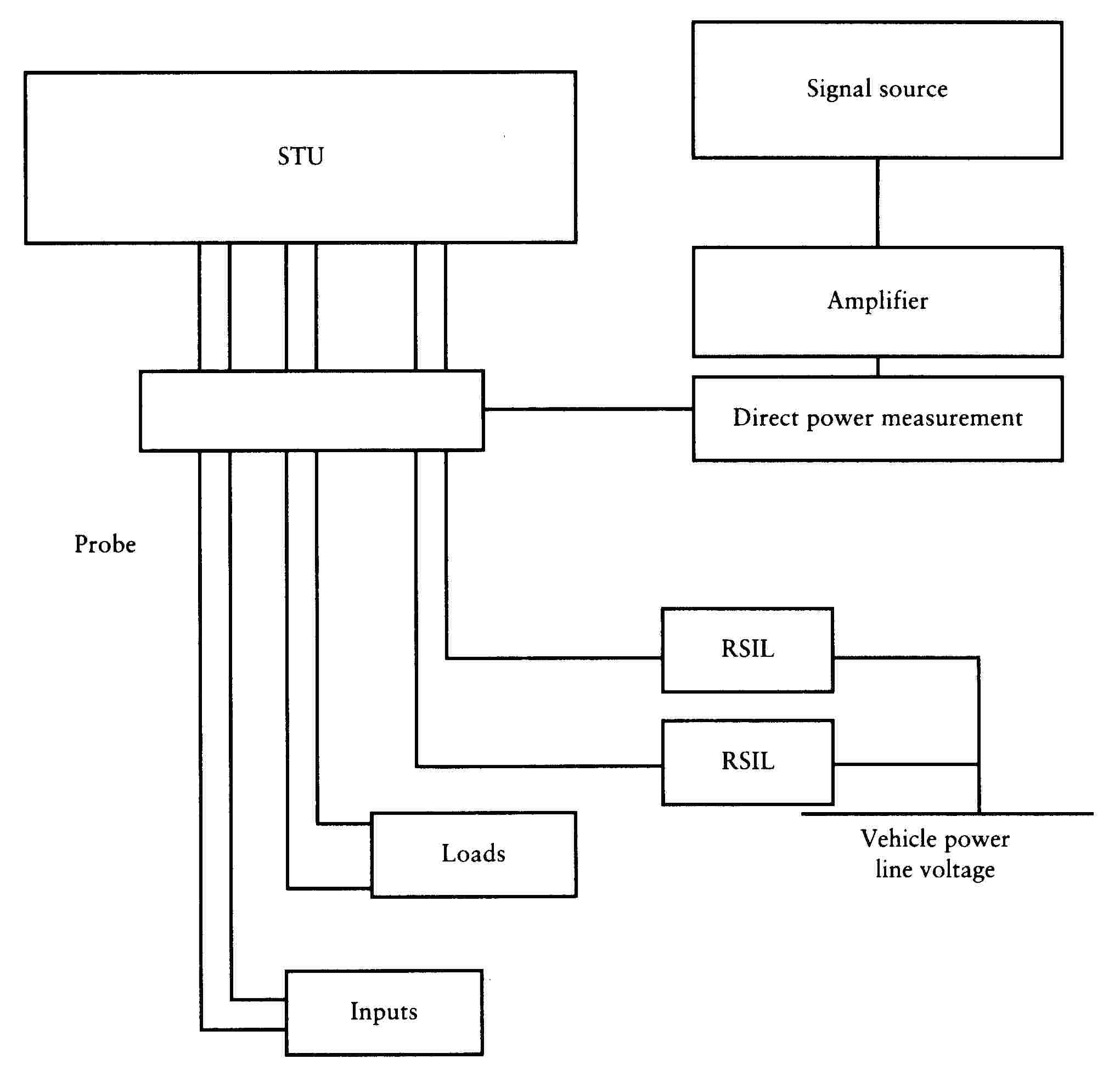
Figure 1
Bulk current injection test

Figure 2
Probe calibration circuit calibration set-up
Appendix 3

Figure 1
TEM-cell test
Appendix 4

Figure 1
Free-field test
ANNEX VIII
Appendix 1
Appendix 2

ANNEX IX
Appendix 1

Appendix 2

CHAPTER 9
PERMISSIBLE SOUND LEVEL AND EXHAUST SYSTEM OF TWO OR THREE-WHEEL MOTOR VEHICLES
LIST OF ANNEXES
|
ANNEX I |
Sound level limits in dB(A) and dates of entry into force for component type-approval regarding the permissible sound level of a type of two or three-wheel motor vehicle |
|
ANNEX II |
Requirements for two-wheel mopeds |
|
1.Definitions |
|
|
2.Component type-approval in respect of the sound level and original exhaust system, as a separate technical unit, of a type of two-wheel moped |
|
|
3.Component type-approval of a non-original exhaust system or components thereof, as separate technical units, for a type of two-wheel moped |
|
|
Appendix 1A |
Information document in respect of the permissible sound level and original exhaust system of a type of two-wheel moped |
|
Appendix 1B |
Component type-approval certificate in respect of the permissible sound level and original exhaust system(s) of a type of two-wheel moped |
|
Appendix 2A |
Information document in respect of a non-original exhaust system or component(s) thereof, as separate technical unit(s), for a type of two-wheel moped |
|
Appendix 2B |
Component type-approval certificate in respect of a non-original exhaust system for a type of two-wheel moped |
|
ANNEX III |
Requirements for motorcycles |
|
1.Definitions |
|
|
2.Component type-approval in respect of the sound level and original exhaust system, as a separate technical unit, of a type of motorcycle |
|
|
3.Component type-approval of a non-original exhaust system or components thereof, as separate technical units, for a type of motorcycle |
|
|
Appendix 1A |
Information document in respect of the permissible sound level and original exhaust system of a type of motorcycle |
|
Appendix 1B |
Component type-approval certificate in respect of the permissible sound level and original exhaust system(s) of a type of motorcycle |
|
Appendix 2A |
Information document in respect of a non-original exhaust system or component(s) thereof, as separate technical unit(s), for a type of motorcycle |
|
Appendix 2B |
Component type-approval certificate in respect of a non-original exhaust system for a type of motorcycle |
|
ANNEX IV |
Requirements for three-wheel mopeds and tricycles |
|
1.Definitions |
|
|
2.Component type-approval in respect of the sound level and original exhaust system, as a separate technical unit, of a type of three-wheel moped or tricycle |
|
|
3.Component type-approval of a non-original exhaust system or components thereof, as separate technical units, for a type of three-wheel moped or tricycle |
|
|
Appendix 1A |
Information document in respect of the permissible sound level and original exhaust system of a type of three-wheel moped or tricycle |
|
Appendix 1B |
Component type-approval certificate in respect of the permissible sound level and original exhaust system(s) of a type of three-wheel moped or tricycle |
|
Appendix 2A |
Information document in respect of a non-original exhaust system or component(s) thereof, as separate technical unit(s), for a type of three-wheel moped or tricycle |
|
Appendix 2B |
Component type-approval certificate for a non-original exhaust system for a type of three-wheel moped or tricycle |
|
ANNEX V |
Production conformity requirements |
|
ANNEX VI |
Marking requirements |
|
Appendix |
Examples of type-approval mark |
|
ANNEX VII |
Test track specifications |
ANNEX I
SOUND LEVEL LIMITS IN dB(A) AND DATES OF ENTRY INTO FORCE FOR COMPONENT TYPE-APPROVAL REGARDING THE PERMISSIBLE SOUND LEVEL OF A TYPE OF TWO OR THREE-WHEEL MOTOR VEHICLE
|
Vehicles |
Sound level limits with effect from 24 months from the date of adoption of this Directive |
|
1.Two-wheel mopeds |
|
|
≤ 25 km/h |
66 |
|
> 25 km/h |
71 |
|
three-wheel mopeds |
76 |
|
2.Motorcycles |
|
|
≤ 80 cm3 |
75 |
|
> 80 ≤ 175 cm3 |
77 |
|
> 175 cm3 |
80 |
|
3.Tricycles |
80 |
ANNEX II
REQUIREMENTS FOR TWO-WHEEL MOPEDS
1. DEFINITIONS
For the purposes of this Chapter:
|
1.1. |
‘type of two-wheel moped as regards its sound level and exhaust system’ means mopeds which do not differ in such essential respects as the following:
|
|
1.2. |
‘exhaust system’ or ‘silencer’ means a complete set of components necessary to limit the noise caused by a moped engine and its exhaust.
|
|
1.3. |
‘exhaust systems of differing types’ means systems which are fundamentally different in one of the following ways:
|
|
1.4. |
‘component of an exhaust system’ means one of the individual components which together form the exhaust system (such as exhaust pipework, the silencer proper) and the intake system (air filter) if any. If the engine has to be equipped with an intake system (air filter and/or intake noise absorber) in order to comply with the maximum permissible sound levels, the filter and/or the absorber must be treated as components having the same importance as the exhaust system. |
2. COMPONENT TYPE-APPROVAL IN RESPECT OF THE SOUND LEVEL AND ORIGINAL EXHAUST SYSTEM, AS A SEPARATE TECHNICAL UNIT, OF A TYPE OF TWO-WHEEL MOPED
2.1. Noise of the two-wheel moped in motion (measuring conditions and method for testing of the vehicle during component type-approval).
2.1.1. Limits: see Annex I.
2.1.2. Measuring instruments
|
2.1.2.1. |
Acoustic measurements The apparatus used for measuring the sound-level must be a precision sound-level meter of the type described in International Electrotechnical Commission (IEC) publication 179 ‘Precision sound-level meters’, second edition. Measurements must be carried out using the ‘fast’ response and the ‘A’ weighting also described in that publication. At the beginning and end of each series of measurements the sound-level meter must be calibrated in accordance with the manufacturer's instructions, using an appropriate sound source (e.g. pistonphone). |
|
2.1.2.2. |
Speed measurements Engine speed and moped speed on the test track must be determined to within ± 3 %. |
2.1.3. Conditions of measurement
|
2.1.3.1. |
Condition of the moped The combined weight of the rider and the test equipment used on the moped must be no more than 90 kg and no less than 70 kg. If necessary, weights must be added to the moped to bring the combined weight up to at least 70 kg. During the measurements the moped must be in running order (including coolant, oils, fuel, tools, spare wheel and rider). Before the measurements are made the moped must be brought to the normal operating temperature. If the moped is fitted with fans with an automatic actuating mechanism, this system must not be interfered with during the sound measurements. For mopeds having more than one driven wheel, only the drive provided for normal road operation may be used. Where a moped is fitted with a sidecar, this must be removed for the purposes of the test. |
|
2.1.3.2. |
Test site The test site must consist of a central acceleration section surrounded by a substantially flat test area. The acceleration section must be flat; its surface must be dry and such that surface noise remains low. On the test site the variations in the free sound field between the sound source at the centre of the acceleration section and the microphone must not exceed 1 dB. This condition will be deemed to be met if there are no large objects which reflect sound, such as fences, rocks, bridges or buildings, within 50 m of the centre of the acceleration section. The road surface covering of the test track must conform to the requirements of Annex VII. The microphone must not be obstructed in any way which could affect the sound field, and no person may stand between the microphone and the sound source. The observer carrying out the measurements must so position himself as not to affect the readings of the measuring instrument. |
|
2.1.3.3. |
Miscellaneous Measurements must not be made in poor atmospheric conditions. It must be ensured that the results are not affected by gusts of wind. For measurements, the A-weighted sound level of sound sources other than those of the vehicle to be tested and of wind effects must be at least 10 dB(A) below the sound level produced by the vehicle. A suitable windscreen may be fitted to the microphone provided that account is taken of its effect on the sensitivity and directional characteristics of the microphone. If the difference between the ambient noise and the measured noise is between 10 and 16 dB(A), in order to calculate the test results the appropriate correction must be subtracted from the readings on the sound-level meter, as in the following graph:
|

2.1.4. Method of measurement
|
2.1.4.1. |
Nature and number of measurements The maximum sound level expressed in A-weighted decibels (dB(A)) must be measured as the moped travels between lines AA′ and BB′ (figure 1). The measurement will be invalid if an abnormal discrepancy between the peak value and the general sound level is recorded. At least two measurements must be taken on each side of the moped. |
|
2.1.4.2. |
Positioning of the microphone The microphone must be located 7,5 m ± 0,2 m from the reference line CC′ (figure 1) of the track and 1,2 m ± 0,1 m above ground level. |
|
2.1.4.3. |
Conditions of operation The moped must approach line AA′ at an initial steady speed ►C2 as specified in 2.1.4.3.1 or 2.1.4.3.2. ◄ When the front of the moped reaches line AA′ the throttle must be fully opened as quicly as practically possible and kept in that position until the rear of the moped reaches line BB′; the throttle must then be returned as quicly as possible to the idle position. For all measurements the moped must be ridden in a straight line over the acceleration section keeping the median longitudinal plane of the moped as close as possible to line CC′.
|
2.1.5. Results (test report)
|
2.1.5.1. |
the test report drawn up for the purpose of issuing the document referred to in Appendix 1B must indicate any circumstances and influences affecting the results of the measurements. |
|
2.1.5.2. |
The values taken must be rounded off to the nearest decibel. If the figure following the decimal point is between 0 and 4, the total is rounded down and if between 5 and 9, it is rounded up. Only those measurements whose variation in two consecutive tests on the same side of the moped is less than or equal to 2 dB(A) may be used for the purpose of issuing the document referred to in Appendix 1B. |
|
2.1.5.3. |
To take account of inaccuracies in the measurements, the result of each measurement must be arrived at by deducting 1 dB(A) from the value obtained in accordance with 2.1.5.2. |
|
2.1.5.4. |
If the average of the four results of the measurements does not exceed the maximum permissible level for the category to which the moped being tested belongs, the limits laid down in 2.1.1 will be deemed as being complied with. This average value will constitute the result of the test. |
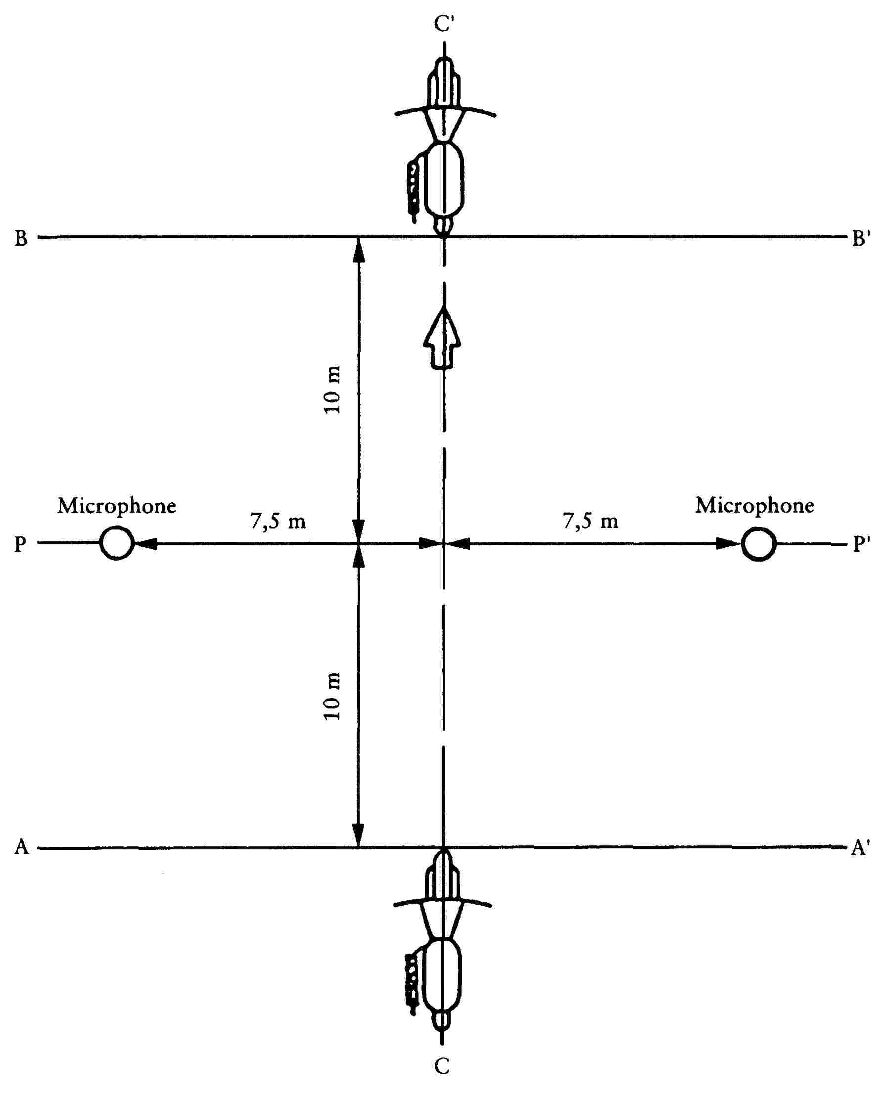
Figure 1
Test for vehicle in motion

Figure 2
Test for stationary vehicle
2.2. Noise from stationary moped (measuring conditions and method for testing of the vehicle in use)
2.2.1. Sound-pressure level in the immediate vicinity of the moped
In order to facilitate subsequent noise tests on mopeds in use, the sound-pressure level must also be measured in the immediate vicinity of the exhaust-system outlet (silencer) in accordance with the following requirements, the result of the measurement being entered in the test report drawn up for the purpose of issuing the document referred to in Appendix 1B.
2.2.2. Measuring instruments
A precision sound-level meter as defined in 2.1.2.1 must be used.
2.2.3. Conditions of measurement
|
2.2.3.1. |
Condition of the moped Before the measurements are made the moped engine must be brought to the normal operating temperature. If the moped is fitted with fans with an automatic actuating mechanism, this system must not be interfered with during the sound measurements. During the measurements the gearbox must be in neutral gear. If it is impossible to disconnect the transmission, the driving wheel of the moped must be allowed to rotate freely, for example by placing the vehicle on its centre stand. |
|
2.2.3.2. |
Test site (Figure 2) Any area in which there are no significant acoustic disturbances may be used as a test site. Flat surfaces which are covered with concrete, asphalt or some other hard material and are highly reflective are suitable; surfaces consisting of earth which has been tamped down must not be used. The test site must be in the form of a rectangle whose sides are at least 3 m from the outer edge of the moped (handlebars excluded). There must be no significant obstacles, e.g. no persons other than the rider and the observer may stand within this rectangle. The moped must be positioned within the said rectangle so that the microphone used for measurement is at least 1 m from any kerb. |
|
2.2.3.3. |
Miscellaneous Readings of the measuring instrument caused by ambient noise and wind effects must be at least 10 dB(A) lower than the sound levels to be measured. A suitable windshield may be fitted to the microphone provided that account is taken of its effect on the sensitivity of the microphone. |
2.2.4. Method of measurement
|
2.2.4.1. |
Nature and number of measurements The maximum sound level expressed in A-weighted decibels (dB(A)) must be measured during the period of operation laid down in 2.2.4.3. At least three measurements must be taken at each measuring point. |
|
2.2.4.2. |
Positioning of the microphone (Figure 2) The microphone must be positioned level with the exhaust outlet or 0,2 m above the surface of the track, whichever is the higher. The microphone diaphragm must face towards the exhaust outlet at a distance of 0,5 m from it. The axis of maximum sensitivity of the microphone must be parallel to the surface of the track at an angle of 45o ± 10o to the vertical plane of the direction of the exhaust emissions. In relation to this vertical plane, the microphone must be located on the side which gives the maximum possible distance between the microphone and the outline of the moped (handlebars excluded). If the exhaust system has more than one outlet at centres less than 0,3 m apart, the microphone must be faced towards the outlet which is nearest the moped (handlebars excluded) or towards the outlet which is highest above the surface of the track. If the centres of the outlets are more than 0,3 m apart, separate measurements must be taken for each of them, the highest figure recorded being taken as the test value. |
|
2.2.4.3. |
Operating conditions The engine speed must be held steady at one of the following values: —
—
where ‘S’ is the speed referred to in section 3.2.1.7 of Appendix 1A. When a constant engine speed is reached, the throttle must be returned swiftly to the idle position. The sound level must be measured during an operating cycle consisting of a brief period of constant engine speed and throughout the deceleration period, the maximum sound-level meter reading being taken as the test value. |
2.2.5. Results (test report)
|
2.2.5.1. |
the test report drawn up for the purpose of issuing the document referred to in Appendix 1B must indicate all relevant data and particularly those used in measuring the noise of the stationary moped. |
|
2.2.5.2. |
Values, rounded off to the nearest decibel, must be read off the measuring instrument. Only those measurements which vary by no more than 2 dB(A) in three consecutive tests will be used. |
|
2.2.5.3. |
The highest of the three measurements constitutes the test result. |
2.3. Original exhaust system (silencer)
|
2.3.1. |
Requirements for silencers containing absorbent fibrous materials
|
||||||||||||||||||||||||||||||||||||||||||||||||||||||||||||||||||||||||||||||
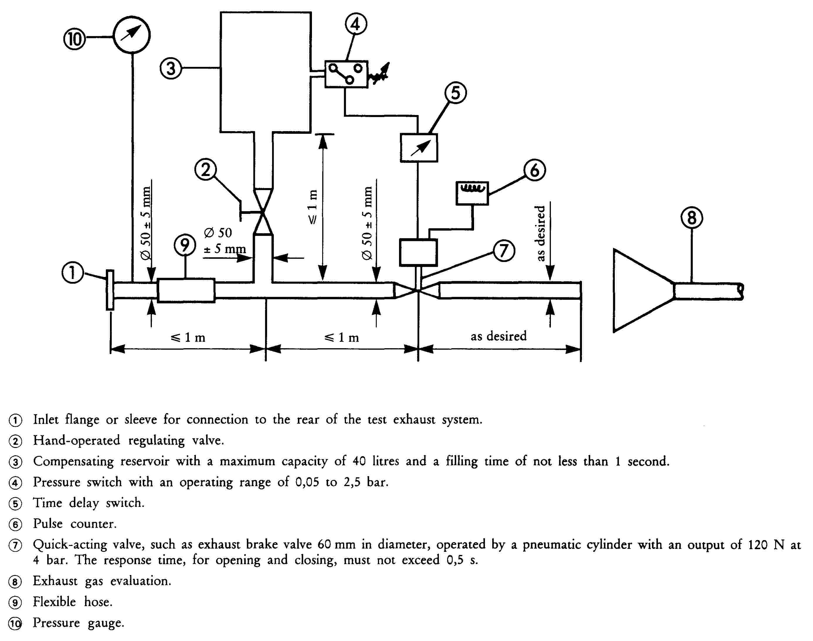
|
2.3.2. |
Diagram and markings
|
|
2.3.3. |
Intake silencer If the engine intake has to be fitted with an air filter and/or intake silencer in order to comply with the permissible sound level, the filter and/or silencer must be regarded as part of the silencer and the requirements of 2.3 will also apply to them. |
3. COMPONENT TYPE-APPROVAL OF A NON-ORIGINAL EXHAUST SYSTEM OR COMPONENTS THEREOF, AS A SEPARATE TECHNICAL UNIT, FOR TWO-WHEEL MOPEDS
This point applies to the component type-approval, as separate technical units, of exhaust systems or components therof intended to be fitted to one or more particular types of moped as non-original replacement parts.
3.1. Definition
|
3.1.1. |
‘Non-original replacement exhaust system or components thereof’ means any exhaust system component as defined in 1.2 intended to be fitted to a moped to replace that of the type fitted to the moped when the document provided for in Appendix 1B was issued. |
3.2. Application for component type-approval
|
3.2.1. |
Applications for component type-approval for replacement exhaust systems or components thereof as separate technical units must be submitted by the manufacturer of the system or by his authorized representative. |
|
3.2.2. |
For each type of replacement exhaust system or components thereof for which approval is requested, the component type-approval application must be accompanied by the following documents in triplicate, and by the following particulars:
|
|
3.2.3. |
The applicant must submit, at the request of the technical service:
|
3.3. Markings and inscriptions
|
3.3.1. |
Non-original exhaust systems or components thereof must be marked in accordance with the requirements of Annex VI. |
3.4. Component type-approval
|
3.4.1. |
Upon completion of the tests laid down in this chapter, the competent authority will issue a certificate based on the model set out in Appendix 2B. The component type-approval number must be preceded by a rectangle surrounding the letter ‘e’ followed by the distinguishing number or letters of the Member State which issued or refused the component type-approval. The exhaust system which is granted component type-approval is deemed to conform to the provisions of Chapter 7. |
3.5. Specifications
3.5.1. General specifications
The design, construction and mounting of the silencer must be such that:
|
3.5.1.1. |
— the moped complies with the requirements of the Chapter under normal conditions of use, and in particular regardless of any vibrations to which it may be subjected; |
|
3.5.1.2. |
— it displays reasonable resistance to the corrosion phenomena to which it is exposed, with due regard to the normal conditions of use of the moped; |
|
3.5.1.3. |
— the ground clearance available under the silencer originally fitted, and the angle at which the moped can lean over, are not reduced; |
|
3.5.1.4. |
— the surface does not reach unduly high temperatures; |
|
3.5.1.5. |
— its outline has no projections or sharp edges; |
|
3.5.1.6. |
— shock absorbers and suspension have adequate clearance; |
|
3.5.1.7. |
— adequate safety clearance is provided for pipes; |
|
3.5.1.8. |
— it is impact-resistant in a way that is compatible with clearly-defined maintenance and installation requirements. |
3.5.2. Specifications for sound levels
|
3.5.2.1. |
The acoustic efficiency of the replacement exhaust systems or components thereof must be tested using the methods described in 2.1.2, 2.1.3, 2.1.4 and 2.1.5. With a replacement exhaust system or component thereof fitted to the moped referred to in 3.2.3.3, the sound-level values obtained must meet the following conditions:
|
3.5.3. Testing of moped performance
|
3.5.3.1. |
The replacement silencer must be such as to ensure that the moped's performance is comparable to that achieved with the original silencer or component thereof. |
|
3.5.3.2. |
The replacement silencer must be compared with an originally-fitted silencer, also in new condition, fitted in turn to the moped referred to in 3.2.3.3. |
|
3.5.3.3. |
This test is carried out by measuring the engine power curve. The net maximum power and the top speed measured with the replacement silencer must not deviate from the net maximum power and top speed measured under the same conditions with the original equipment silencer by more than ± 5 %. |
|
3.5.4. |
Additional provisions relating to silencers as separate technical units containing fibrous material. Fibrous material may not be used in the construction of such silencers unless the requirements set out in section 2.3.1 of this Annex are met. |
|
3.5.5. |
Evaluation of the emission of pollutants of vehicles equipped with replacement silencer system The vehicle referred to in section 3.2.3.3, equipped with a silencer of the type for which approval is requested, shall undergo a Type I and a Type II test under the conditions described in the corresponding Annex to Chapter 5 annexed to this Directive according to the type-approval of the vehicle. The requirements regarding emissions shall be deemed to be fulfilled if the results meet the limit values according to the type-approval of the vehicle. |
Appendix 1A

Appendix 1B

Appendix 2A

Appendix 2B

ANNEX III
REQUIREMENTS FOR MOTORCYCLES
1. DEFINITIONS
For the purposes of this Chapter:
|
1.1. |
‘type of motorcycle as regards its sound level and exhaust system’ means motorcycles which do not differ in such essential respects as the following:
|
|
1.2. |
‘exhaust system’ or ‘silencer’ means a complete set of components necessary to limit the noise caused by a motorcycle engine and its exhaust.
|
|
1.3. |
‘exhaust systems of differing types’ means systems which are fundamentally different in one of the following ways:
|
|
1.4. |
‘component of an exhaust system’ means one of the individual components which together form the exhaust system (such as exhaust pipework, the silencer proper) and the intake system (air filter) if any. If the engine has to be equipped with an intake system (air filter and/or intake noise absorber) in order to comply with the maximum permissible sound levels, the filter and/or the absorber must be treated as components having the same importance as the exhaust system. |
|
1.5. |
‘Hybrid electric vehicle (HEV)’ means a vehicle that, for the purpose of mechanical propulsion, draws energy from both of the following on-vehicle sources of stored energy: (a) a consumable fuel; (b) an electrical energy storage device (e.g.: battery, capacitor, flywheel/generator etc.) …. |
2. COMPONENT TYPE-APPROVAL IN RESPECT OF THE SOUND LEVEL AND ORIGINAL EXHAUST SYSTEM, AS A SEPARATE TECHNICAL UNIT, OF A TYPE OF MOTORCYCLE
2.1. Noise of the motorcycle in motion (measuring conditions and method for testing of the vehicle during component type-approval)
2.1.1. Limits: see Annex I.
2.1.2. Measuring instruments
|
2.1.2.1. |
Acoustic measurements The apparatus used for measuring the sound level must be a precision sound-level meter of the type described in International Electrotechnical Commission (IEC) publication 179 ‘Precision sound-level meters’, second edition. Measurements must be carried out using the ‘fast’ response and the ‘A’ weighting also described in that publication. At the beginning and end of each series of measurements the sound-level meter must be calibrated in accordance with the manufacturer's instructions, using an appropriate sound source (e.g. pistonphone). |
|
2.1.2.2. |
Speed measurements Engine speed and motorcycle speed on the test track must be determined to within ± 3 %. |
2.1.3. Conditions of measurement
|
2.1.3.1. |
Condition of the motorcycle During the measurements the motorcycle must be in running order (including coolant, oils, fuel, tools, spare wheel and rider). Before the measurements are made the motorcycle must be brought to the normal operating temperature. If the motorcycle is fitted with fans with an automatic actuating mechanism, this system must not be interfered with during the sound measurements. For motorcycles having more than one driven wheel, only the drive provided for normal road operation may be used. Where a motorcycle is fitted with a sidecar, this must be removed for the purposes of the test. |
|
2.1.3.2. |
Test site The test site must consist of a central acceleration section surrounded by a substantially flat test area. The acceleration section must be flat; its surface must be dry and such that surface noise remains low. On the test site the variations in the free sound field between the sound source at the centre of the acceleration section and the microphone must not exceed 1 dB. This condition will be deemed to be met if there are no large objects which reflect sound, such as fences, rocks, bridges or buildings, within 50 m of the centre of the acceleration section. The road surface covering of the test site must conform to the requirements of Annex VII. The mircrophone must not be obstructed in any way which could affect the sound field, and no person may stand between the microphone and the sound source. The observer carrying out the measurements must so position himself as not to affect the readings of the measuring instrument. |
|
2.1.3.3. |
Miscellaneous Measurements must not be made in poor atmospheric conditions. It must be ensured that the results are not affected by gusts of wind. For measurements, the A-weighted sound level of sound sources other than those of the vehicle to be tested and of wind effects must be at least 10 dB(A) below the sound level produced by the vehicle. A suitable windscreen may be fitted to the microphone provided that account is taken of its effect on the sensitivity and directional characteristics of the microphone. If the difference between the ambient noise and the measured noise is between 10 and 16 dB(A), in order to calculate the test results the appropriate correction must be subtracted from the readings on the sound-level meter, as in the following graph:
|

2.1.4. Method of measurement
|
2.1.4.1. |
Nature and number of measurements The maximum sound level expressed in A-weighted decibels (dB(A)) must be measured as the motorcycle travels between lines AA′ and BB′ (figure 1). The measurement will be invalid if an abnormal discrepancy between the peak value and the general sound level is recorded. At least two measurements must be taken on each side of the motorcycle. |
|
2.1.4.2. |
Positioning of the microphone The microphone must be located 7,5 m ± 0,2 m from the reference line CC′ (Figure 1) of the track and 1,2 m ± 0,1 m above ground level. |
|
2.1.4.3. |
Conditions of operation The motorcycle must approach line AA′ at an initial steady speed as specified in 2.1.4.3.1 and 2.1.4.3.2. When the front of the motorcycle reaches line AA′ the throttle must be fully opened as quickly as practically possible and kept in that position until the rear of the motorcycle reaches line BB′; the throttle must then be returned as quickly as possible to the idle position. For all measurements the motorcycle must be ridden in a straight line over the acceleration section keeping the longitudinal median plane of the motorcycle as close as possible to line CC′.
|
|
2.1.4.4. |
In case of Hybrid vehicle the tests have to be performed 2 times: (a) Condition A: Batteries shall be at their maximum state of charge; if more than one ‘hybrid mode’ is available, the most electric hybrid mode shall be selected for the test; (b) Condition B: Batteries shall be at their minimum state of charge; if more than one ‘hybrid mode’ is available, the most fuel consuming hybrid mode shall be selected for the test. |
2.1.5. Results (test report)
|
2.1.5.1. |
The test report drawn up for the purpose of issuing the document referred to in Appendix 1B must indicate any circumstances and influences affecting the results of the measurements. |
|
2.1.5.2. |
Readings taken must be rounded off to the nearest decibel. If the figure following the decimal point is between 0 and 4, the total is rounded down and if between 5 and 9, it is rounded up. Only those measurements whose variation in two consecutive tests on the same side of the motorcycle is less than or equal to 2 dB(A) may be used for the purpose of issuing the document referred to in Appendix 1B. |
|
2.1.5.3. |
To take account of inaccuracies in the measurements, the result of each measurement must be arrived at by deducting 1 dB(A) from the value obtained in accordance with 2.1.5.2. |
|
2.1.5.4. |
If the average of the four results of the measurements does not exceed the maximum permissible level for the category to which the vehicle being tested belongs, the limit laid down in 2.1.1 will be deemed as being complied with. This average value will constitute the result of the test. |
|
2.1.5.5. |
If the average of four results of Condition A and if the average of four results of Condition B do not exceed the maximum permissible level for the category to which the vehicle being tested belongs, the limits laid down in point 2.1.1 shall be deemed as being complied with. The highest average value shall constitute the result of the test. |
2.2. Noise from stationary motorcycle (measuring conditions and method for testing of the vehicle in use)
2.2.1. Sound-pressure level in the immediate vicinity of the motorcycle
In order to facilitate subsequent noise tests on motorcycles in use, the sound-pressure level must also be measured in the immediate vicinity of the exhaust-system outlet in accordance with the following requirements, the result of the measurement being entered in the test report drawn up for the purpose of issuing the document referred to in Appendix 1B.
2.2.2. Measuring instruments
A precision sound-level meter as defined in 2.1.2.1 must be used.
2.2.3. Conditions of measurement
|
2.2.3.1. |
Condition of the motorcycle Before the measurements are made the motorcycle engine must be brought to the normal operating temperature. If the motorcycle is fitted with fans with an automatic actuating mechanism, this system must not be interfered with during the sound measurements. During the measurements the gearbox must be in neutral gear. If it is impossible to disconnect the transmission, the driving wheel of the motorcycle must be allowed to rotate freely, for example by placing the vehicle on its centre stand. |
|
2.2.3.2. |
Test site (Figure 2) Any area in which there are no significant acoustic disturbances may be used as a test site. Flat surfaces which are covered with concrete, asphalt or some other hard material and are highly reflective are suitable; surfaces consisting of earth which has been tamped down must not be used. The test site must be in the form of a rectangle whose sides are at least 3 m from the outer edge of the motorcycle (handlebars excluded). There must be no significant obstacles, e.g. no persons other than the rider and the observer may stand within this rectangle. The motorcycle must be positioned within the said rectangle so that the microphone used for measurement is at least 1 m from any kerb. |
|
2.2.3.3. |
Miscellaneous Readings of the measuring instrument caused by ambient noise and wind effects must be at least 10 dB(A) lower than the sound levels to be measured. A suitable windshield may be fitted to the microphone provided that account is taken of its effect on the sensitivity of the microphone. |
2.2.4. Method of measurement
|
2.2.4.1. |
Nature and number of measurements The maximum sound level expressed in A-weighted decibels (dB(A)) must be measured during the period of operation laid down in 2.2.4.3. At least three measurements must be taken at each measuring point. |
|
2.2.4.2. |
Positioning of the microphone (Figure 2) The microphone must be positioned level with the exhaust outlet or 0,2 m above the surface of the track, whichever is the highest. The microphone diaphragm must face towards the exhaust outlet at a distance of 0,5 m from it. The axis of maximum sensitivity of the microphone must be parallel to the surface of the track at an angle of 45o ± 10o to the vertical plane of the direction of the exhaust emissions. In relation to this vertical plane, the microphone must be located on the side which gives the maximum possible distance between the microphone and the outline of the motorcycle (handlebars excluded). If the exhaust system has more than one outlet at centres less than 0,3 m apart, the microphone must be faced towards the outlet which is nearest the motorcycle (handlebars excluded) or towards the outlet which is highest above the surface of the track. If the centres of the outlets are more than 0,3 m apart, separate measurements must be taken for each of them, the highest figure recorded being taken as the test value. |
|
2.2.4.3. |
Operating conditions The engine speed must be held steady at one of the following values: —
—
where S is the speed referred to in section 3.2.1.7 of Appendix 1A. When a constant engine speed is reached, the throttle must be returned swiftly to the idle position. The sound level must be measured during an operating cycle consisting of a brief period of constant engine speed and throughout the deceleration period, the maximum sound-level meter reading being taken as the test value. |
2.2.5. Results (test report)
|
2.2.5.1. |
The test report drawn up for the purpose of issuing the document referred to in Appendix 1B must indicate all relevant data and particularly those used in measuring the noise of the stationary motorcycle. |
|
2.2.5.2. |
Values, rounded off to the nearest decibel, must be read off the measuring instrument. If the figure following the decimal point is between 0 and 4, the total is rounded down and if between 5 and 9, it is rounded up. Only those measurements which vary by no more than 2 dB(A) in three consecutive tests will be used. |
|
2.2.5.3. |
The highest of the three measurements will constitute the test result. |

Figure 1
Test for vehicle in motion
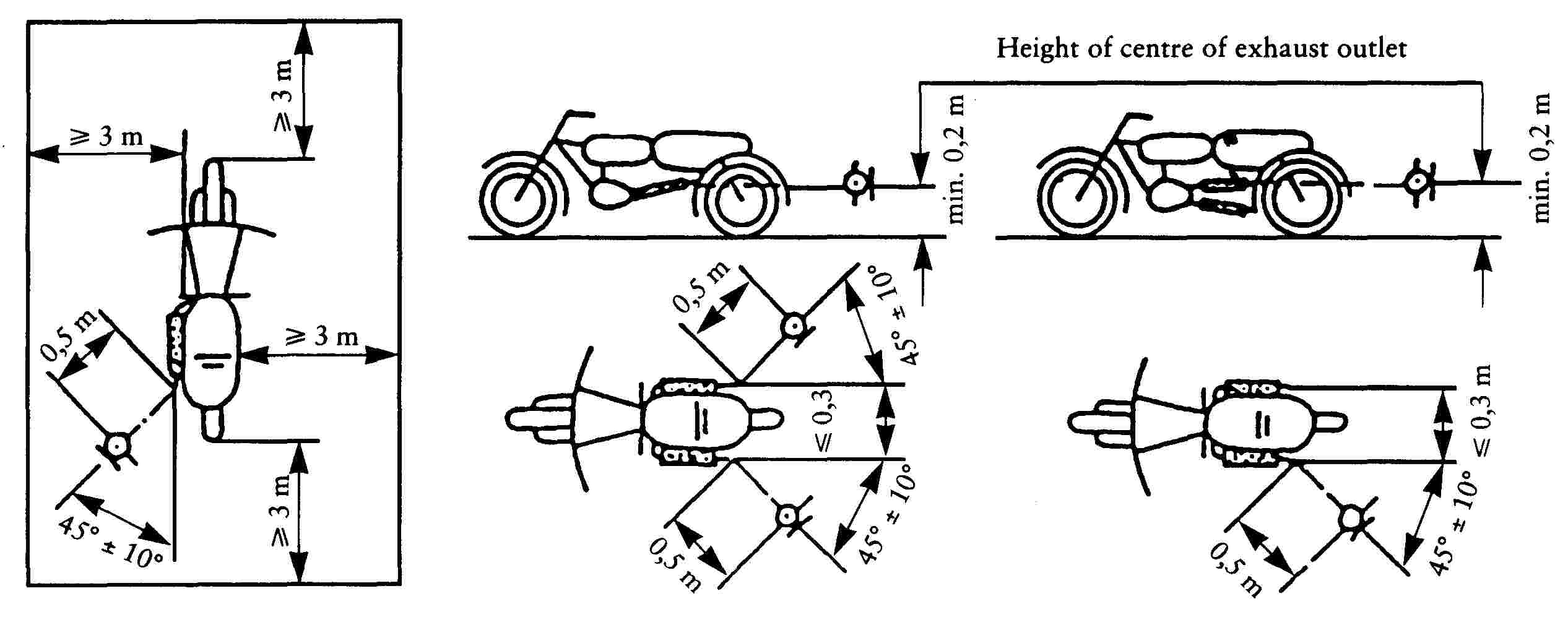
Figure 2
Test for stationary vehicle
2.3. Original exhaust system (silencer)
2.3.1. Requirements for silencers containing absorbent fibrous materials
|
2.3.1.1. |
Absorbent fibrous material must be asbestos-free and may be used in the construction of silencers only if it is securely held in place thoughout the service life of the silencer and it meets the requirements of any one of 2.3.1.2, 2.3.1.3 or 2.3.1.4. |
|
2.3.1.2. |
After removal of the fibrous material, the sound level must comply with the requirements of 2.1.1. |
|
2.3.1.3. |
The absorbent fibrous material may not be placed in those parts of the silencer through which the exhaust gases pass and must comply with the following requirements:
|
|
2.3.1.4. |
Before the system is tested in accordance with 2.1, it must be put into normal working order by one of the following methods:
Figure 3 Test apparatus for conditioning by pulsation |
||||||||||||||||||||||||||||||||||||||||||||||||||||||||||||||||||||||||||||||||||||||||||
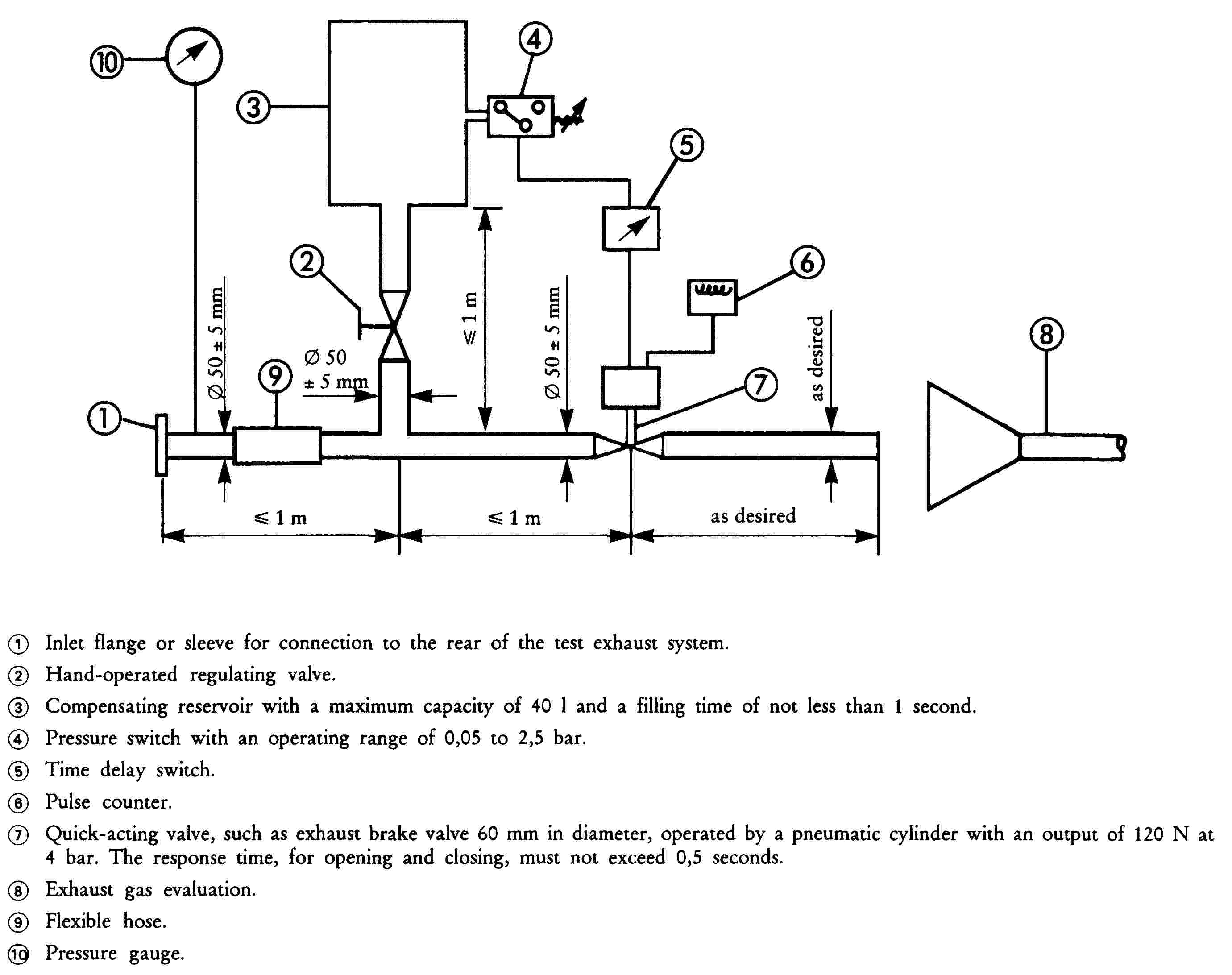
2.3.2. Diagram and markings
|
2.3.2.1. |
A diagram and a cross-sectional drawing indicating the dimensions of the exhaust system must be annexed to the document referred to in Appendix 1A. |
|
2.3.2.2. |
All original silencers shall bear at least the following identifications: — the ‘e’ mark followed by the identification of the country which granted the type-approval, — the vehicle manufacturer's name or trade mark, — the make and identifying part number. This reference must be legible and indelible and also visible, in the position at which it is to be fitted. |
|
2.3.2.3. |
Any packing of original replacement silencer systems must be marked legibly with the words ‘original part’ and the make and type references integrated together with the ‘e’ mark and also the reference of the country of origin. |
2.3.3. Intake silencer
If the engine intake has to be fitted with an air filter and/or intake silencer in order to comply with the permissible sound level, the filter and/or silencer must be regarded as part of the silencer and the requirements of 2.3 also apply to them.
3. COMPONENT TYPE-APPROVAL OF A NON-ORIGINAL EXHAUST SYSTEM OR COMPONENTS THEREOF, AS TECHNICAL UNITS, FOR MOTORCYCLES
This section applies to the component type-approval, as technical units of exhaust sytems or components thereof intended to be fitted to one or more particular types of motorcycle as non-original replacement parts.
3.1. Definition
|
3.1.1. |
‘Non-original replacement exhaust system or components thereof’ means any exhaust system component as defined in 1.2 intended to be fitted to a motorcycle to replace that of the type fitted to the motorcycle when the document provided for in Appendix 1B was issued. |
3.2. Application for component type-approval
|
3.2.1. |
Applications for component type-approval for replacement exhaust systems or components thereof as separate technical units must be submitted by the manufacturer of the system or by his authorized representative. |
|
3.2.2. |
For each type of replacement exhaust system or components thereof for which approval is requested, the component type-approval application must be accompanied by the following documents in triplicate, and by the following particulars:
|
|
3.2.3. |
The applicant must submit, at the request of the technical authority:
|
3.3. Markings and inscriptions
|
3.3.1. |
Non-originnal exhaust systems or components thereof must be marked in accordance with the requirements of Annex VI. |
3.4. Component type-approval
|
3.4.1. |
Upon completion of the tests laid down in this Chapter, the competent authority will issue a certificate corresponding to the model shown in Appendix 2B. The component type-approval number must be preceded by a rectangle surrounding the letter ‘e’ followed by the distinguishing number or letters of the Member State which issued or refused the component type-approval. The exhaust system which is granted component type-approval is deemed to conform to the provisions of Chapter 1. |
3.5. Specifications
|
3.5.1. |
General specifications The design, construction and mounting of the silencer must be such that:
|
|
3.5.2. |
Specifications for sound levels
|
|
3.5.3. |
Testing of motorcycle performance
|
|
3.5.4. |
Additional provisions relating to silencers as separate technical units containing fibrous material. Fibrous material may not be used in the construction of such silencers unless the requirements set out in 2.3.1 are met. |
|
3.5.5. |
Evaluation of the emission of pollutants of vehicles equipped with replacement silencer system The vehicle referred to in section 3.2.3.3, equipped with a silencer of the type for which approval is requested, shall undergo a Type I and a Type II test under the conditions described in the corresponding Annex to Chapter 5 annexed to this Directive according to the type-approval of the vehicle. The requirements regarding emissions shall be deemed to be fulfilled if the results meet the limit values according to the type-approval of the vehicle. |
Appendix 1A
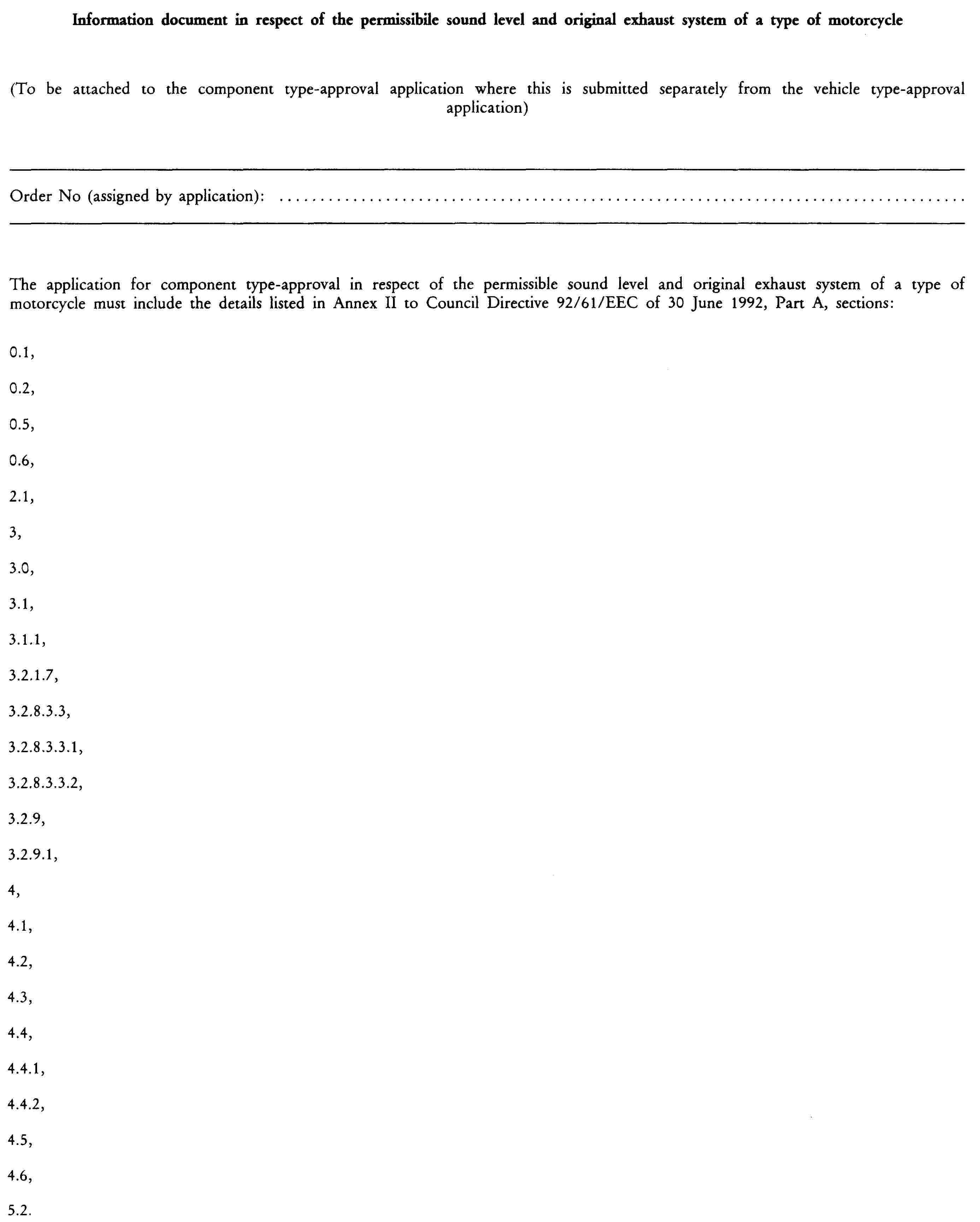
Appendix 1B
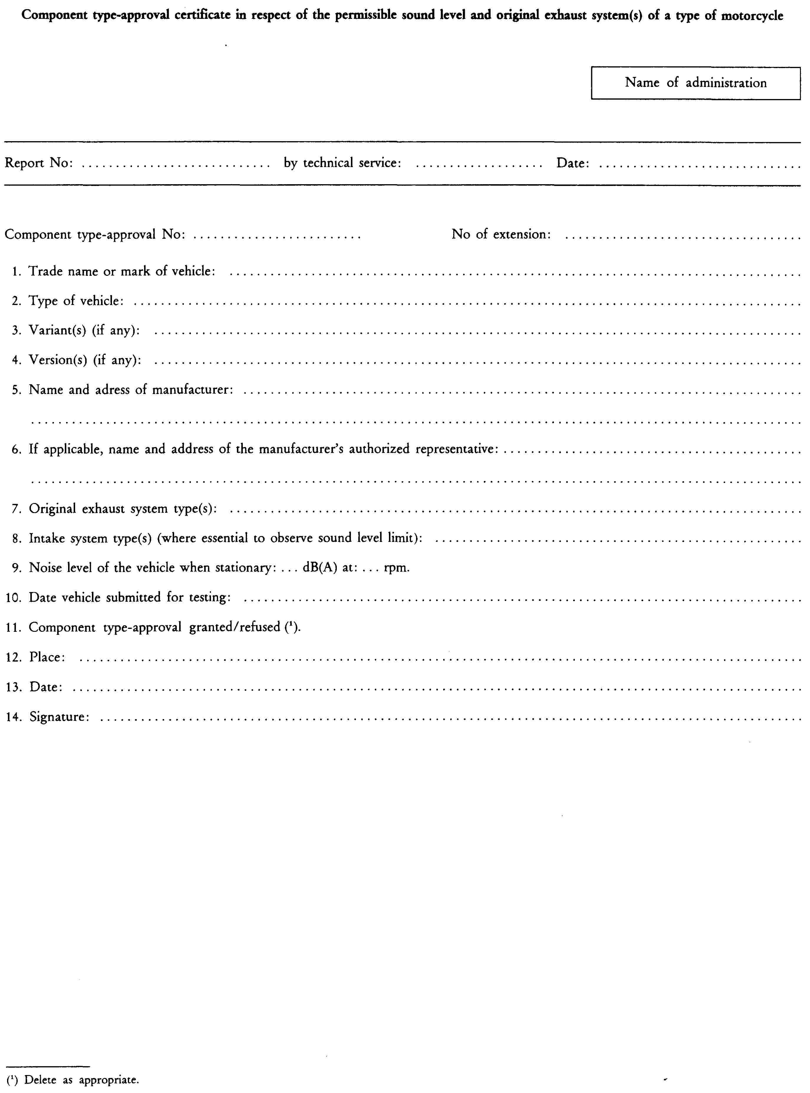
Appendix 2A

Appendix 2B

ANNEX IV
REQUIREMENTS FOR THREE-WHEEL MOPEDS AND TRICYCLES
1. DEFINITIONS
For the purposes of this Chapter:
|
1.1. |
‘type of three-wheel moped or tricycle as regards its sound level and exhaust system’ means three-wheel mopeds and tricycles which do not differ in such essential respects as the following:
|
|
1.2. |
‘exhaust system’ or ‘silencer’ means a complete set of components necessary to limit the noise caused by the engine and exhaust of a three-wheel moped or tricycle.
|
|
1.3. |
‘exhaust systems of differing types’ means systems which are fundamentally different in one of the following ways:
|
|
1.4. |
‘component of an exhaust system’ means one of the individual components which together form the exhaust system (such as exhaust pipework, the silencer proper) and the intake system (air filter) if any. If the engine has to be equipped with an intake system (air filter and/or intake noise absorber) in order to comply with maximum permissible sound levels, the filter and/or the absorber must be treated as a component having the same importance as the exhaust system. |
|
1.5. |
‘Hybrid electric vehicle (HEV)’ means a vehicle that, for the purpose of mechanical propulsion, draws energy from both of the following on-vehicle sources of stored energy: (a) a consumable fuel; (b) an electrical energy storage device (e.g.: battery, capacitor, flywheel/generator etc.)…. |
2. COMPONENT TYPE-APPROVAL IN RESPECT OF THE SOUND LEVEL AND ORIGINAL EXHAUST SYSTEM, AS A SEPARATE TECHNICAL UNIT, OF A TYPE OF THREE-WHEEL MOPED OR TRICYCLE
2.1. Noise of the three-wheel moped or tricycle (measuring conditions and method for testing of the vehicle during component type-approval).
|
2.1.1. |
The vehicle, its engine and its exhaust system must be designed, constructed and assembled so that the vehicle complies with the requirements of this chapter under normal conditions of use, regardless of any vibrations to which they may be subjected. |
|
2.1.2. |
The exhaust system must be designed, constructed and mounted to resist the corrosion phenomena to which it is exposed. |
2.2. Specifications for sound levels
2.2.1. Limits: see Annex I.
2.2.2. Measuring instruments
|
2.2.2.1. |
The apparatus used for measuring the sound level must be a precision sound-level meter of the type described in International Electrotechnical Commission (IEC) publication No 179 ‘Precision sound-level meters’, second edition. Measurements must be carried out using the ‘fast’ response of the sound-level meter and the ‘A’ weighting also described in that publication. At the beginning and end of each series of measurements the sound-level meter must be calibrated in accordance with the manufacturer's instructions, using an appropriate sound source (e.g. a pistonphone). |
|
2.2.2.2. |
Speed measurements Engine speed and vehicle speed on the test track must be determined to within ± 3 %. |
2.2.3. Conditions of measurement
|
2.2.3.1. |
Condition of the vehicle During the measurements, the vehicle must be in the running order (including coolant, oils, fuel, tools, spare wheel and rider). Before the measurements are made the vehicle must be brought to the normal operating temperature.
|
|
2.2.3.2. |
Test site The test site must consist of a central acceleration section surrounded by a substantially flat test area. The acceleration section must be flat; its surface must be dry and such that surface noise remains low. On the test site the variations in the free sound field between the sound source at the centre of the acceleration section and the micropohone must not exceed ± 1 dB. This condition will be deemed to be met if there are no large objects which reflect sound, such as fences, rocks, bridges or buildings, within 50 m of the centre of the acceleration section. The road surface covering of the test track must conform to the requirements of Annex VII. The microphone must not be obstructed in any way which could affect the sound field, and no person may stand between the microphone and the sound source. The observer carrying out the measurements must so position himself as not to affect the readings of the measuring instrument. |
|
2.2.3.3. |
Miscellaneous Measurements must not be made in poor atmospheric conditions. It must be ensured that the results are not affected by gusts of wind. For measurements, the A-weighted sound level of sound sources other than those of the vehicle to be tested and of wind effects must be at least 10 dB(A) below the sound level produced by the vehicle. A suitable windscreen may be fitted to the microphone provided that account is taken of its effect on the sensitivity and directional characteristics of the microphone. It the difference between the ambient noise and the measured noise is between 10 and 16 dB(A), in order to calculate the test results the appropriate correction must be subtracted from the readings on the sound-level meter, as in the following graph:
|
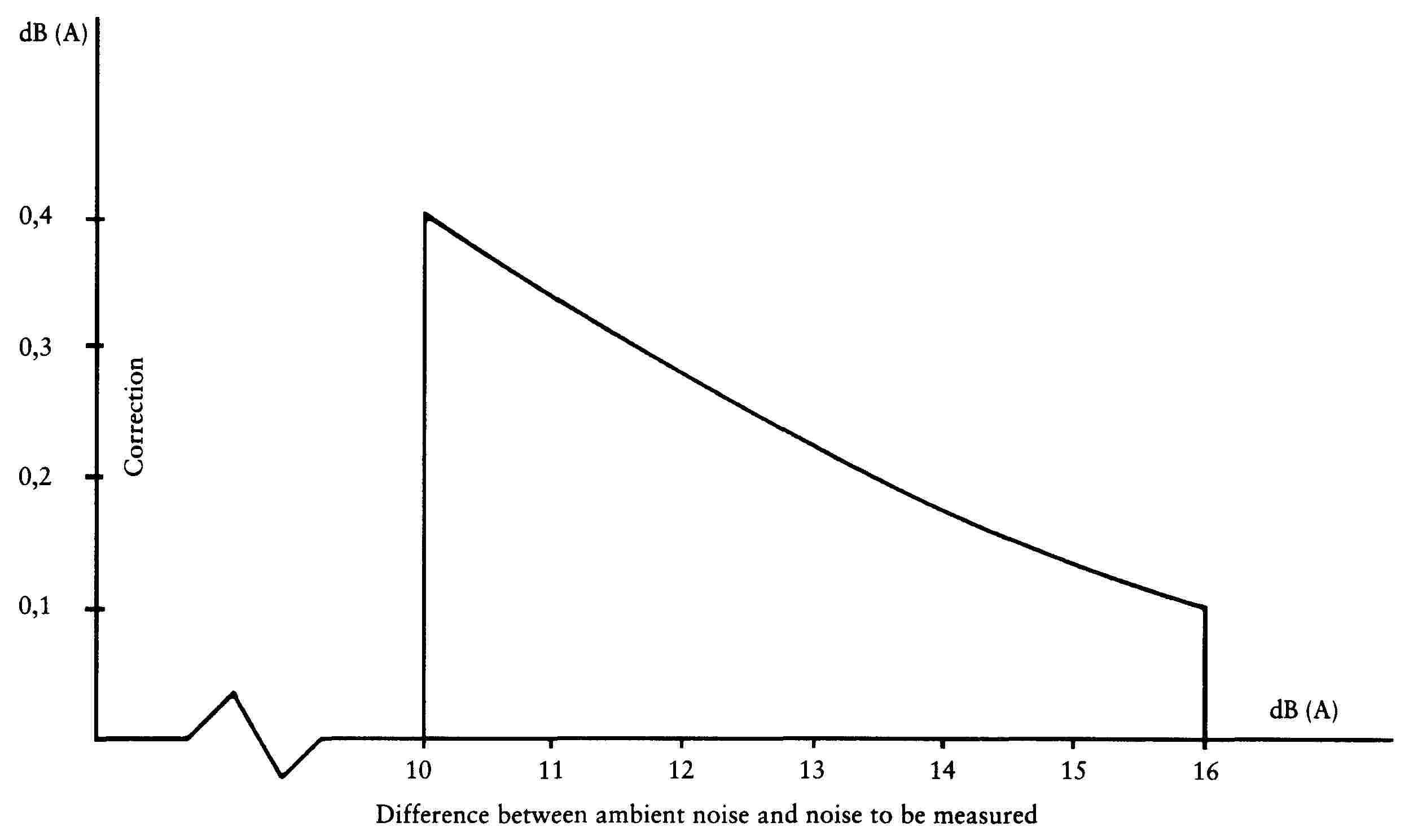
2.2.4. Method of measurement
|
2.2.4.1. |
Nature and number of measurements The maximum sound level expressed in A-weighted decibels (dB(A)) must be measured as the vehicle travels between lines AA′ and BB′ (figure 1). The measurement will be invalid if an abnormal discrepancy between the peak value and the general sound level is recorded. At least two measurements must be taken on each side of the vehicle. |
|
2.2.4.2. |
Positioning of the microphone The microphone must be located 7,5 m ± 0,2 m from the reference line CC′ (Figure 1) of the track and 1,2 m ± 0,1 m above ground level. |
|
2.2.4.3. |
Conditions of operation The vehicle must approach line AA′ at an initial steady speed as specified in 2.2.4.4. When the front of the vehicle reaches line AA′ the throttle must be fully opened as quickly as practically possible and kept in that position until the rear of the vehicle reaches line BB′; the throttle must then be returned as quickly as possible to the idle position. For all measurements the vehicle must be ridden in a straight line over the acceleration section keeping the median longitudinal plane of the vehicle as close as possible to line CC′.
|
|
2.2.4.4. |
Determining the steady speed to be adopted
|
|
2.2.4.5. |
In case of Hybrid vehicle the tests have to be performed 2 times: (a) Condition A: Batteries shall be at their maximum state of charge; if more than one ‘hybrid mode’ is available, the most electric hybrid mode shall be selected for the test (b) Condition B: Batteries shall be at their minimum state of charge; if more than one ‘hybrid mode’ is available, the most fuel consuming hybrid mode shall be selected for the test. |
2.2.5. Results (test report)
|
2.2.5.1. |
The test report drawn up for the purpose of issuing the document referred to in Appendix 1B must indicate any circumstances and influences affecting the results of the measurements. |
|
2.2.5.2. |
The values taken must be rounded off to the nearest decibel. If the figure following the decimal point is between 0 and 4, the total is rounded down and if between 5 and 9, it is rounded up. Only those measurements whose variation in two consecutive tests on the same side of the vehicle is less than or equal to 2 dB(A) may be used for the purpose of issuing the document referred to in Appendix 1B. |
|
2.2.5.3. |
To take account of inaccuracies in the measurements, the result of each measurement must be arrived at by deducting 1 dB(A) from the value obtained in accordance with 2.2.5.2. |
|
2.2.5.4. |
If the average of the four results of the measurements does not exceed the maximum permissible level for the category to which the vehicle being tested belongs, the limit laid down in 2.2.1 will be deemed as being complied with. This average value will constitute the result of the test. |
|
2.2.5.5. |
If the average of four results of Condition A and if thes average of four results of Condition B do not exceed the maximum permissible level for the category to which the vehicle being tested belongs, the limits laid down in point 2.2.1 shall be deemed as being complied with. The highest average value shall constitute the result of the test. |
2.3. Measurement of the noise of the stationary vehicle (for testing the vehicle in use)
|
2.3.1. |
Sound-pressure level in the immediate vicinity of the vehicle. In order to facilitate subsequent noise tests on vehicles in use, the sound-pressure level must also be measured in the immediate vicinity of the exhaust-system outlet (silencer) in accordance with the following requirements, the result of the measurement being entered in the test report drawn up for the purpose of issuing the document referred to in Appendix 1B. |
|
2.3.2. |
Measuring instruments A precision sound-level meter conforming in accuracy to 2.2.2.1 must be used. |
|
2.3.3. |
Conditions of measurement
|
|
2.3.4. |
Method of measurement
|
|
2.3.5. |
Results (test report)
|
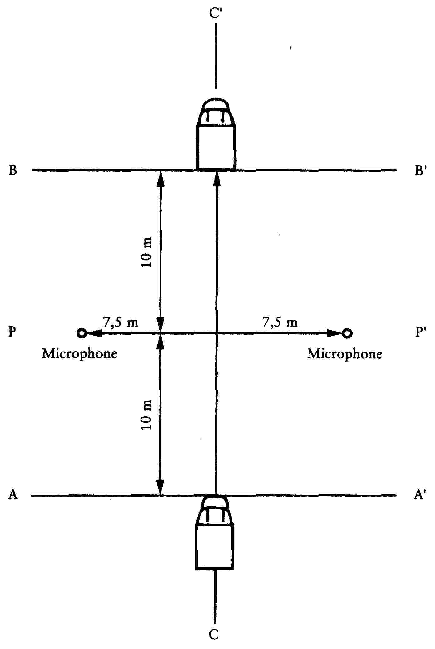
Figure 1
Positions for testing the vehicle in motion

Figure 2
Positions for testing the stationary vehicle
2.4. Original exhaust system (silencer)
2.4.1. Requirements for silencers containing absorbent fibrous materials
|
2.4.1.1. |
Absorbent fibrous material must be asbestos-free and may be used in the construction of silencers only if it is securely held in place throughout the service life of the silencer and it meets the requirements of any one of 2.4.1.2, 2.4.1.3 or 2.4.1.4. |
|
2.4.1.2. |
After removal of the fibrous material, the sound level must comply with the requirements of 2.2.1. |
|
2.4.1.3. |
The absorbent fibrous material may not be placed in those parts of the silencer through which the exhaust gases pass and must comply with the following requirements.
|
|
2.4.1.4. |
Before the system is tested in accordance with section 2, it must be put into normal working order by one of the following methods:
Figure 3 Test apparatus for conditioning by pulsation |
||||||||||||||||||||||||||||||||||||||||||||||||||||||||||||||||||||||||||||||||||||||||||
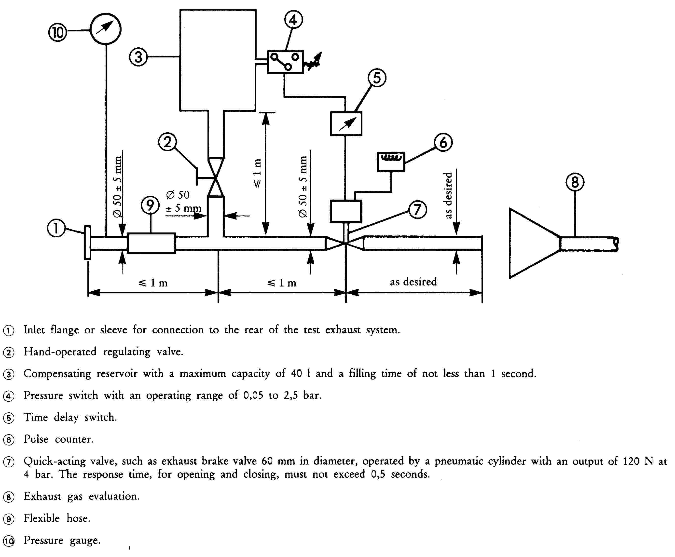
2.4.2. Diagram and markings
|
2.4.2.1. |
A diagram and a cross-sectional drawing indicating the dimensions of the exhaust system must be annexed to the document referred to in Appendix 1A. |
|
2.4.2.2. |
All original silencers shall bear at least the following identifications: — the ‘e’ mark followed by the identification of the country which granted the type-approval, — the vehicle manufacturer's name or trade mark, — the make and identifying part number. This reference must be legible and indelible and also visible, in the position at which it is to be fitted. |
|
2.4.2.3. |
Any packing of original replacement silencer systems must be marked legibly with the words ‘original part’ and the make and type references integrated together with the ‘e’ mark and also the reference of the country of origin. |
2.4.3. Intake silencer
If the engine intake has to be fitted with an air filter and/or intake silencer in order to comply with the permissible sound level, the filter and/or silencer must be regarded as part of the silencer and the requirements of 2.4 will also apply to them.
3. COMPONENT TYPE-APPROVAL IN RESPECT OF A NON-ORIGINAL EXHAUST SYSTEM OR COMPONENTS THEREOF, AS SEPARATE TECHNICAL UNITS, FOR THREE-WHEEL MOPEDS AND TRICYCLES
This section applies to the component type-approval, as separate technical units, of exhaust systems or components thereof intended to be fitted to one or more particular types of three-wheel mopeds and tricycles as non-original replacement parts.
3.1. Definition
|
3.1.1. |
‘Non-original replacement exhaust system or components thereof’ means any exhaust system component as defined in 1.2 intended to be fitted to a three-wheel moped or tricycle to replace that of the type fitted to the three-wheel moped or tricycle when the document provided for in Appendix 1B was issued. |
3.2. Application for component type-approval
|
3.2.1. |
Applications for component type-approval for replacement exhaust systems or components thereof as separate technical units must be submitted by the manufacturer of the system or by his authorized representative. |
|
3.2.2. |
For each type of replacement exhaust system or components thereof for which approval is requested, the application for component type-approval must be accompanied by the following documents in triplicate, and by the following particulars:
|
|
3.2.3. |
The applicant must submit, at the request of the technical service:
|
3.3. Markings and inscriptions
|
3.3.1. |
Non-original exhaust systems or components thereof must be marked in accordance with the requirements of Annex VI. |
3.4. Component type-approval
|
3.4.1. |
Upon completion of the tests laid down in this Chapter, the competent authority will issue a certificate corresponding to the model shown in Appendix 2B. The component type-approval number must be preceded by a rectangle surrounding the letter ‘e’ followed by the distinguishing number or letters of the Member State which issued or refused the component type-approval. |
3.5. Specifications
3.5.1. General specifications
The design, construction and mounting of the silencer must be such that:
|
3.5.1.1. |
— the vehicle complies with the requirements of the chapter under normal conditions or use, and in particular regardless of any vibrations to which it may be subjected; |
|
3.5.1.2. |
— it displays reasonable resistance to the corrosion phenomena to which it is exposed, with due regard to the normal conditions of use of the vehicle; |
|
3.5.1.3. |
— the ground clearance available under the silencer originally fitted, and the angle at which the vehicle can lean over, are not reduced; |
|
3.5.1.4. |
— the surface does not reach unduly high temperatures; |
|
3.5.1.5. |
— its outline has no projections or sharp edges; |
|
3.5.1.6. |
— shock absorbers and suspension have adequate clearance; |
|
3.5.1.7. |
— adequate safety clearance is provided for pipes; |
|
3.5.1.8. |
— it is impact-resistant in a way that is compatible with clearly-defined maintenance and installation requirements. |
3.5.2. Specifications for sound levels
|
3.5.2.1. |
The acoustic efficiency of the replacement exhaust systems or components thereof must be tested using the methods described in 2.3, 2.4, 2.5 and 2.6. With a replacement exhaust system or component thereof fitted to the vehicle referred to in 3.2.3.3 of this Annex, the sound-level values obtained must meet the following conditions:
|
3.5.3. Testing of vehicle performance
|
3.5.3.1. |
The replacement silencer must be such as to ensure that the vehicle's performance is comparable to that achieved with the original silencer or component thereof. |
|
3.5.3.2. |
The replacement silencer must be compared with an originally-fitted silencer, also in new condition, fitted in turn to the vehicle referred to in 3.2.3.3. |
|
3.5.3.3. |
This test is carried out by measuring the engine power curve. The net maximum power and the top speed measured with the replacement silencer must not deviate from the net maximum power and top speed measured under the same conditions with the original equipment silencer by more than ± 5 %. |
3.5.4. Additional provisions relating to silencers as separate technical units containing fibrous material
Fibrous material may not be used in the construction of such silencers unless the requirements set out in 2.4.1 are met.
3.5.5. Evaluation of the emission of pollutants of vehicles equipped with replacement silencer system
The vehicle referred to in section 3.2.3.3, equipped with a silencer of the type for which approval is requested, shall undergo a Type I and a Type II test under the conditions described in the corresponding Annex to Chapter 5 annexed to this Directive according to the type-approval of the vehicle.
The requirements regarding emissions shall be deemed to be fulfilled if the results meet the limit values according to the type-approval of the vehicle.
Appendix 1A

Appendix 1B
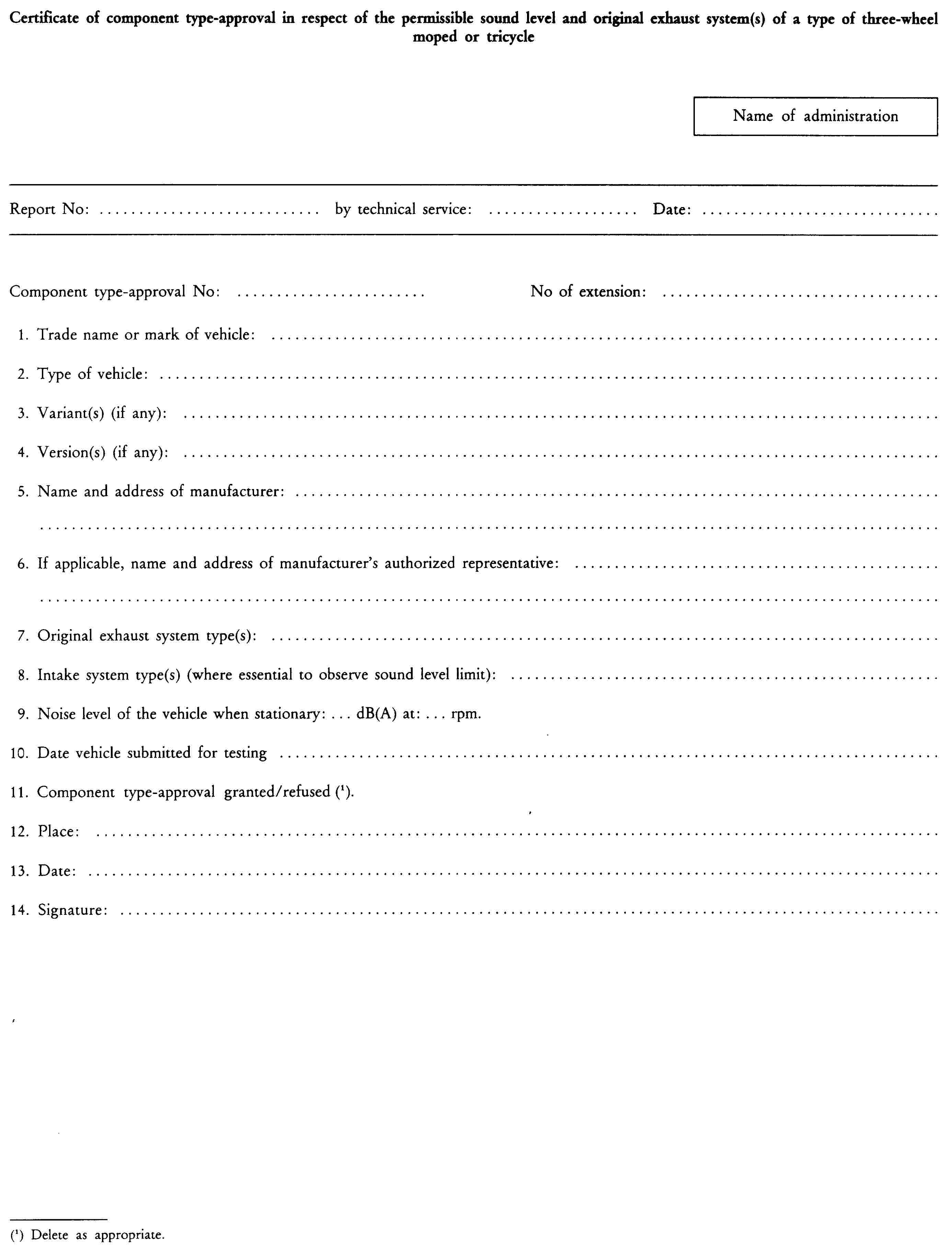
Appendix 2A

Appendix 2B

ANNEX V
PRODUCTION CONFORMITY REQUIREMENTS
1. VEHICLE CONFORMITY
Any vehicle manufactured must conform to a type of vehicle approved pursuant to this Chapter, be equipped with the silencer with which it was type-approved and satisfy the requirements of section 2 of the Annex relating to the type of vehicle concerned.
In order to test conformity as required above, a sample vehicle will be taken from the production line of the type approved pursuant to this Chapter. Production will be regarded as conforming to the provisions of this Chapter if the sound level measured using the method described in section 2.1 of each Annex does not exceed by more than 3 dB(A) the value measured at the time of type-approval, nor by more than 1 dB(A) the limits laid down in this Chapter.
2. CONFORMITY OF A NON-ORIGINAL REPLACEMENT EXHAUST SYSTEM
Any exhaust system manufactured must conform to a type approved pursuant to this Chapter and satisfy the requirements of section 3 of the Annex relating to the type of vehicle for which it is intended.
In order to test conformity as required above, a sample exhaust will be taken from the production line of the type approved pursuant to this Chapter.
Production will be regarded as conforming to the provisions of this Chapter if the requirements of sections 3.5.2 and 3.5.3 of each Annex are satisfied and if the sound level measured using the method described in section 2.1 of each Annex does not exceed by more than 3 dB(A) the value measured at the time of type-approval, nor by more than 1 dB(A) the limits laid down in this chapter.
ANNEX VI
MARKING REQUIREMENTS
|
1. |
Non-original exhaust system or components thereof, but not the mounting parts and pipes, must bear:
|
|
2. |
The marks referred to in 1.1 and 1.3 and the name referred to in 1.2 must be indelible and clearly legible even when the exhaust system is fitted to the vehicle. |
|
3. |
A component may bear several type-approval numbers if it has been type-approved as a component of several replacement exhaust systems. |
|
4. |
The replacement exhaust system must be supplied with packaging or labelling bearing the following:
|
|
5. |
The manufacturer must supply the following:
|
|
6. |
FURTHER INFORMATION CONTAINED IN THE TYPE-APPROVAL MARK
|
Appendix
Examples of type-approval mark

The above represented type-approval mark was issued by France [e2] under number 6789 for a non-original exhaust system consisting of a sole part integrating both the silencer and the catalytic converter.

The above represented type-approval mark was issued by France [e2] under number 6789 for a non-original silencer not integrating a catalytic converter (catalytic converter and silencer not integrated in a sole element or vehicle not equipped with a catalytic converter)
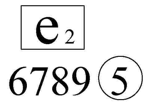
The above represented type-approval mark was issued by France [e2] under number 6789 for the replacement catalytic converter not integrated in the exhaust system (catalytic converter and silencer not integrated in a sole element) (see Chapter 5).
The above represented type-approval mark was issued by France [e2] under number 6789 for a non-original exhaust system consisting of a sole part (silencer) intended to be fitted on vehicles which are not type-approved according to Chapter 5.
ANNEX VII
TEST TRACK SPECIFICATIONS
This Annex lays down specifications relating to the physical characteristics of the paving and the layout of the test track paving.
1. REQUIRED CHARACTERISTICS OF SURFACE
A surface is considered to conform to this Directive provided that the texture and voids content or sound absorption coefficient have been measured and found to fulfill all the requirements given in 1.1 to 1.4 and provided that the design requirements (section 2.2) have been met.
1.1. Residual voids content
The residual voids content, Vc, of the test track paving mixture must not exceed 8 %. See section 3.1 for measurement procedure.
1.2. Sound absorption coefficient
If the surface fails to comply with the residual voids content requirement, the surface is acceptable only if its sound absorption coefficient, α, is ≤ 0,10. See section 3.2 or measurement procedure.
The requirement of section 1.1 and 1.2 is met also if only sound absorption has been measured and found to be: α ≤ 0,10.
1.3. Texture depth
The texture depth (TD) measured according to the volumetric method (see section 3.3) shall be:
TD ≥ 0,4 mm.
1.4. Homogeneity of the surface
Every practical effort must be taken to ensure that the surface is made to be as homogenous as possible within the test area. This includes the texture and voids content, but it should also be observed that if the rolling process results in more effective rolling at some places than at others, the texture may be different and uneverness causing bumps may also occur.
1.5. Period of testing
In order to check whether the surface continues to conform to the texture and voids content or sound absorption requirements stipulated in this standard, periodic testing of the surface must be performed at the following intervals:
(a) for residual voids content or sound absorption:
— when the surface is new.
— if the surface meets the requiremens when new, no further periodical testing is required.
If it does not meet the requirement when it is new, it may do so later because surfaces tend to become clogged and compacted with time;
(b) for texture depth (TD):
— when the surface is new,
— when the noise testing starts (NB: not before four weeks after laying).
— then every twelve months
2. TEST SURFACE DESIGN
2.1. Area
When designing the test track layout it is important to ensure that, as a minimum requirement, the area traversed by the vehicles running through the test strip is covered with the specified test material with suitable margins for safe and practical driving. This will require that the width of the track is at least 3 m and the length of the track extends beyond lines AA and BB by at least 10 m at either end. Figure 1 shows a plan of a suitable test site and indicates the minimum area which, must be machine laid and machine compacted with the specified test surface material.

Figure 1
Minimum requirements for test surface area
2.2. Design requirements for the surface
The test surface must meet four design requirements:
1. it must be a dense asphaltic concrete;
2. the maximum chipping size must be 8 mm (tolerances allow from 6,3 to 10 mm);
3. the thickness of the wearing couse must be ≥ 30 mm;
4. the binder must be a straight penetration grade bitumen without modification.
As a guide to the test surface constructor, an aggregate grading curve which will give desired characteristics is shown in figure 2. In addition, table 3 gives some guidelines in order to obtain the desired texture and durability. The grading curve fits the following formula:
P (% passing) = 100 (d/dmax) 1/2
where
|
d |
= |
square mesh sieve size, in mm |
|
dmax |
= |
8 mm for the mean curve |
|
dmax |
= |
10 mm for the lower tolerance curve |
|
dmax |
= |
6,3 mm for the upper tolerance curve |
In addition to the above, the following recommendations are given:
— the sand fraction (0,063 mm < square mesh sieve size < 2 mm) should include no more than 55 % natural sand and least 45 % crushed sand,
— the base and sub-base should ensure a good stability and evenness, according to best road construction practice,
— the chippings should be crushed (100 % crushed faces) and of a material with a high resistance to crushing,
— the chippings used in the mix should be washed,
— no extra chippings should be added on to the surface,
— the binder hardness expressed as PEN value should be 40 to 60, 60 to 80 or even 80 to 100, depending on the climatic conditions of the country. The rule is that as hard a binder as possible should be used, provided this is consistent with common practice,
— the temperature of the mix before rolling should be chosen so as to achieve by subsequent rolling the required voids content. In order to increase the probability or satisfying the specifications of sections 1.1 to 1.4, the compactness should be studied not only by an appropriate choice of mixing temperature, but also by an appropriate number of passings and by the choice of compacting vehicle.
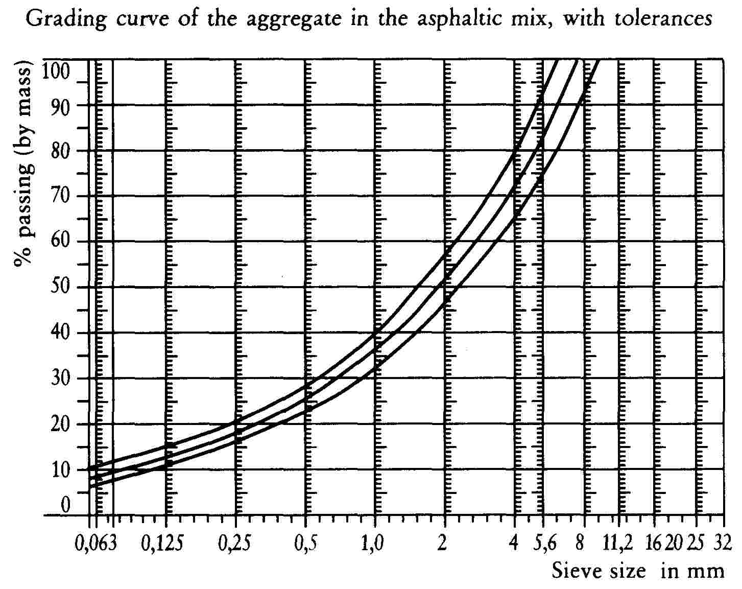
Figure 2
Table 3
Design guidelines
|
Target values |
Tolerances |
||
|
By total mass of mix |
By mass of the approcase |
||
|
Mass of stones, Square Mesh Sieve (SM) > 2 mm |
47,6 % |
50,5 % |
± 5 |
|
Mass of sand 0,063 < SM < 2 mm |
38,0 % |
40,2 % |
± 5 |
|
Mass of filter SM < 0,063 mm |
8,8 % |
9,3 % |
± 2 |
|
Mass of binder (bitumen) |
5,8 % |
N.A. |
± 0,5 |
|
Maximum chipping size |
8 mm |
6,3-10 |
|
|
Binder hardness |
(see below) |
||
|
Polished stone value (PSV) (see doc. 5 in bibliography) |
> 50 |
||
|
Compactness, relative to Marshall compactness |
98 % |
||
3. TEST METHODS
3.1. Measurement of the residual voids content
For the purpose of this measurement, cores have to be taken from the track at least at four different positions which are equally distributed in the test area between lines AA and BB (see figure 1). In order to avoid inhomogeneity and unevenness in the wheel tracks, cores should not be taken in the wheel tracks themselves, but close to them. Two cores (minimum) should be taken close to the wheel tracks and one core (minimum) should be taken approximately midway between the wheel tracks and each microphone location.
If there is a suspicion that the condition of homogeneity in not met (see section 1.4), cores should be taken from more locations within the test area.
The residual voids content has to be determined for each core. Then the average value from all cores is calculated and compared with the requirement of section 1.1. In addition, no single core should have a voids value which is higher than 10 %.
The test surface constructor is reminded of the problem which may arise when the test area is heated by pipes or electrical wires and cores must be taken from this area. Such installations must be carefully planned with respect to future core drilling locations. It is recommended to leave a few locations of size approximately 200 × 300 mm where there are no wires or pipes, or where the latter are located deep enough in order not to be damaged by cores taken from the surface layer.
3.2. Sound absorption coefficient
The sound absorption coefficient (normal incidence) is measured by the impedance tube method using the procedure specified in ISO/DIS 10534: ‘Acoustics — Determination of sound absorption coefficient and impedance by a tube method’.
Regarding test specimens, the same requirements are followed as regarding the residual voids content (see section 3.1).
The sound absorption is measured in the range 400 to 800 Hz and in the range 800 to 1 600 Hz (at least at the centre frequencies of third octave bands) and the maximum values shall be identified for both of these frequency ranges. Then these values, for all test cores, are averged to constitute the final result.
3.3. Volumetric macrotexture measurement
For the purposes of this standard, texture depth measurements are made on at least 10 positions evenly spaced along the wheel tracks of the test strip and the average value taken to compare with the specified minimum texture depth. See Annex F to Draft Standard ISO/DIS 10844 for a description of the procedure.
4. STABILITY IN TIME AND MAINTENANCE
4.1. Age influence
In common with many other surfaces, is it expected that the tyre/road noise levels measured on the test surface may increase slightly during the first six to 12 months after construction.
The surface will achieve its required characteristics not earlier than four weeks after construction.
The stability over time is determined mainly by the polishing and compaction by vehicles driving on the surface. It must be periodically checked as stated in section 1.5.
4.2. Maintenance of the surface
Loose debris or dust which could significantly reduce the effective texture depth must be removed from the surface. In countries with winter climates, salt is sometimes used for de-icing. Salt may alter the surface temporarily or even permanently in such a way as to increase noise and is therefore not recommended.
4.3. Repaving the test area
If it is necessary to repave the test track, it is usually unnecessary to repave more than the test strip (of 3 m width in figure 1) where vehicles are driving provided the test area outside the strip met the requirement of residual voids content or sound absorption when it was measured.
5. DOCUMENTATION OF THE SURFACE AND OF TESTS PERFORMED ON IT
5.1. Documentation of the test surface
The following data must be given in a document describing the test surface:
(a) the location of the test track;
(b) type of binder, binder hardness, type of aggregate, maximum theoretical density of the concrete (‘DR’), thickness of the wearing course and grading curve determined from cores from the test track;
(c) method of compaction (e.g. type of roller, roller mass, number of passes);
(d) temperature of the mix, temperature of the ambient air and wind speed during laying of the surface;
(e) date when the surface was laid and contractor;
(f) all or at least the latest test result, including:
(i) the residual voids content of each core;
(ii) the locations in the test area from where the cores for voids measurement have been taken;
(iii) the sound absorption coefficient of each core (if measured). Specify the results both for each core and each frequency range as well as the overall average;
(iv) the locations in the test area from where the cores for absorption measurement have been taken;
(v) texture depth, including the number of tests and standard deviation;
(vi) the institution responsible for tests (i) and (iii) and the type of equipment used;
(vii) date of the test(s) and date when the cores were taken from the test track.
5.2. Documentation of vehicle noise tests concluded on the surface
In the document describing the vehicle noise test(s) it must be stated whether all the requirements were fulfilled or not. Reference must be made to a document in accordance with section 5.1.
CHAPTER 10
TRAILER COUPLING DEVICES OF TWO OR THREE-WHEEL MOTOR VEHICLES
ANNEX AND APPENDICES
|
ANNEX I |
Trailer coupling devices of two or three-wheel motor vehicles |
|
Appendix 1 |
Ball coupling on two or three-wheel motor vehicles |
|
Appendix 2 |
|
|
Appendix 3 |
|
|
Appendix 4 |
Information document in respect of coupling devices for trailers towed by a type of two or three-wheel motor vehicle |
|
Appendix 5 |
Component type-approval certificate in respect of coupling devices for trailers towed by a type of two or three-wheel motor vehicle |
ANNEX I
TRAILER COUPLING DEVICES OF TWO OR THREE-WHEEL MOTOR VEHICLES
1. SCOPE
|
1.1. |
This Annex I applies to coupling devices for two and three-wheel motor vehicles and their attachment to these vehicles. |
|
1.2. |
This Annex I states the requirements which coupling devices for two and three-wheel motor vehicles must satisfy in order to — ensure compatibility when combining motor vehicles with different types of trailers; — ensure the safe coupling together of the vehicles under all conditions of use; — ensure safe procedures for coupling and uncoupling. |
2. DEFINITIONS
|
2.1. |
‘Coupling devices for motor vehicles’ means all parts and devices fitted to the frames, load-bearing parts of the bodywork and chassis of the vehicles by means of which towing and towed vehicles are connected together. They also include fixed or detachable parts for the attachment, adjustment or operation of the abovementioned coupling devices.
|
3. GENERAL REQUIREMENTS
|
3.1. |
The coupling devices for two and three-wheel motor vehicles must be manufactured and attached in accordance with good engineering practice, and must be safe to operate. |
|
3.2. |
The coupling devices must be so designed and manufactured that in normal use, with proper maintenance and the timely replacement of wearing parts, they will continue to function satisfactorily. |
|
3.3. |
Every coupling device must be accompanied by installation and operating instructions giving sufficient information for a competent person to install it on the vehicle and operate it properly. The instructions must be in the official language or languages of the Member State in which the coupling device will be offered for sale. |
|
3.4. |
The materials that may be used are those for which the properties relevant to the application are laid down in a standard or those for which the properties are given in the application documentation. |
|
3.5. |
All parts of the coupling devices whose failure could result in separation of the two vehicles must be made of steel. Other materials may be used provided equivalence has been demonstrated by the manufacturer to the satisfaction of the Technical Service. |
|
3.6. |
All couplings must be designed for positive mechanical engagement, and the closed position must be secured at least once by positive mechanical engagement. |
|
3.7. |
In principle coupling balls in accordance with Appendix 1, Figure 1 are to be used on two and three-wheel motor vehicles. In the case of three-wheel vehicles particularly, the coupling type must be chosen and positioned to allow maximum compatibility with a range of trailer types. Devices other than coupling balls may be used, provided the requirements of 3.8 are met and that compatibility and interchangeability of trailers is neither necessary nor possible (dedicated combinations). |
|
3.8. |
Coupling devices must be designed in a way to meet the requirements for case of operation, position, mobility and strength according to Sections 3.9, 3.10, 3.11, 4, 5 and 6. |
|
3.9. |
The coupling devices must be designed and attached in a way to achieve maximum safety according to good engineering practice; this also applies to the operation of the coupling. |
|
3.10. |
Safe coupling and uncoupling of the vehicles must be possible by one person without the use of tools. |
|
3.11. |
The operation of detachable coupling devices must be possible easily by hand and without the use of tools. |
4. REQUIREMENTS FOR POSITION
|
4.1. |
Coupling devices attached to the vehicles must ensure an unhindered and safe operation. |
|
4.2. |
Coupling balls attached to the vehicles must correspond to the geometric conditions specified in Appendix 1, Figure 2. |
|
4.3. |
The height of the coupling point of a coupling device other than a coupling ball must correspond to the height of the coupling point of the drawbar of the trailer within a range of ± 35 mm, provided the trailer is in a horizontal position. |
|
4.4. |
The shape and the dimensions of the towing brackets must correspond to the vehicle manufacturer's requirements with respect to fixing points and any additional mounting devices required. |
|
4.5. |
The requirements of the vehicle manufacturer with regard to the type of the coupling device, the permissible mass of the trailer and the permissible static vertical load imposed at the coupling point must be observed. |
|
4.6. |
The mounted coupling device must not obscure the visibility of the rear licence plate, otherwise a coupling device which can be dismantled without special tools has to be used. |
5. REQUIREMENTS FOR ARTICULATION
|
5.1. |
The following articulation must be possible with the coupling device not attached to the vehicle.
|
|
5.2. |
At all angles of horizontal rotation the following combinations of articulation must be possible: in the case of two-wheel vehicles, except where the device is used with one-wheel trailers which tilt with the two-wheel motor vehicle: — vertical pitch of ± 15o with axial roll of ± 40o, — axial roll of ± 30o with vertical pitch of ± 20o; in the case of three-wheel vehicles or quadricycles: — vertical pitch of ± 15o with axial roll of ± 25o — axial roll of ± 10o with vertical pitch of ± 20o. |
|
5.3. |
It must also be possible to couple and uncouple ball couplings when the longitudinal axis of the ball coupling in relation to the centre line of the coupling ball and mounting: — is horizontally β = 60o right or left — is vertically α = 10o up or down — is axially rotated 10o right or left. |
6. REQUIREMENTS FOR STRENGTH
|
6.1. |
A dynamic strength test (endurance test) must be performed.
|
|
6.2. |
Test procedures
|
|
6.3. |
Test of coupling balls and towing brackets
|
|
6.4. |
The abovementioned testing requirements in 6.3.1 are also applicable to coupling devices other than coupling balls. |
7. COUPLING HEADS
|
7.1. |
The basic test is an endurance test with an alternating test force and a static test (lifting test) on each test sample. |
|
7.2. |
The dynamic test must be performed with a suitable coupling ball of appropriate strength. On the test rig the coupling head and the ball coupling must be arranged as instructed by the manufacturer and in a way corresponding to their attachment in a vehicle. There must be no possibility of extra forces in addition to the test force acting on the sample. The test force must be applied along a line passing through the centre of the ball and inclined downwards to the rear at 15o (see Appendix 3, Figure 6). An endurance test must be performed on a test sample with the following test force: Fres = ± 0,6 D |
|
7.3. |
A static lifting test must also be performed (see Appendix 3, Figure 7). The coupling ball used for the test must have a diameter of 49– 0 +0,13 mm in order to represent a worn coupling ball. The lifting force FA must be increased smoothly and quickly to a value of
and held for 10 seconds, where
|
|
7.4. |
If coupling devices other than ball couplings are used, the coupling head must be tested, as applicable, in accordance with the relevant requirements of Directive 94/20/EC. |
8. MARKING
Coupling devices must be marked in accordance with the relevant requirements of Directive 94/20/EC.
Appendix 1
Ball coupling on two or three-wheel motor vehicles
The ball coupling system for trailers does not exclude the use of other systems (for instance cardan couplings); however, if a ball-coupling system is used, this system must correspond to the specification laid down in Figure 1.
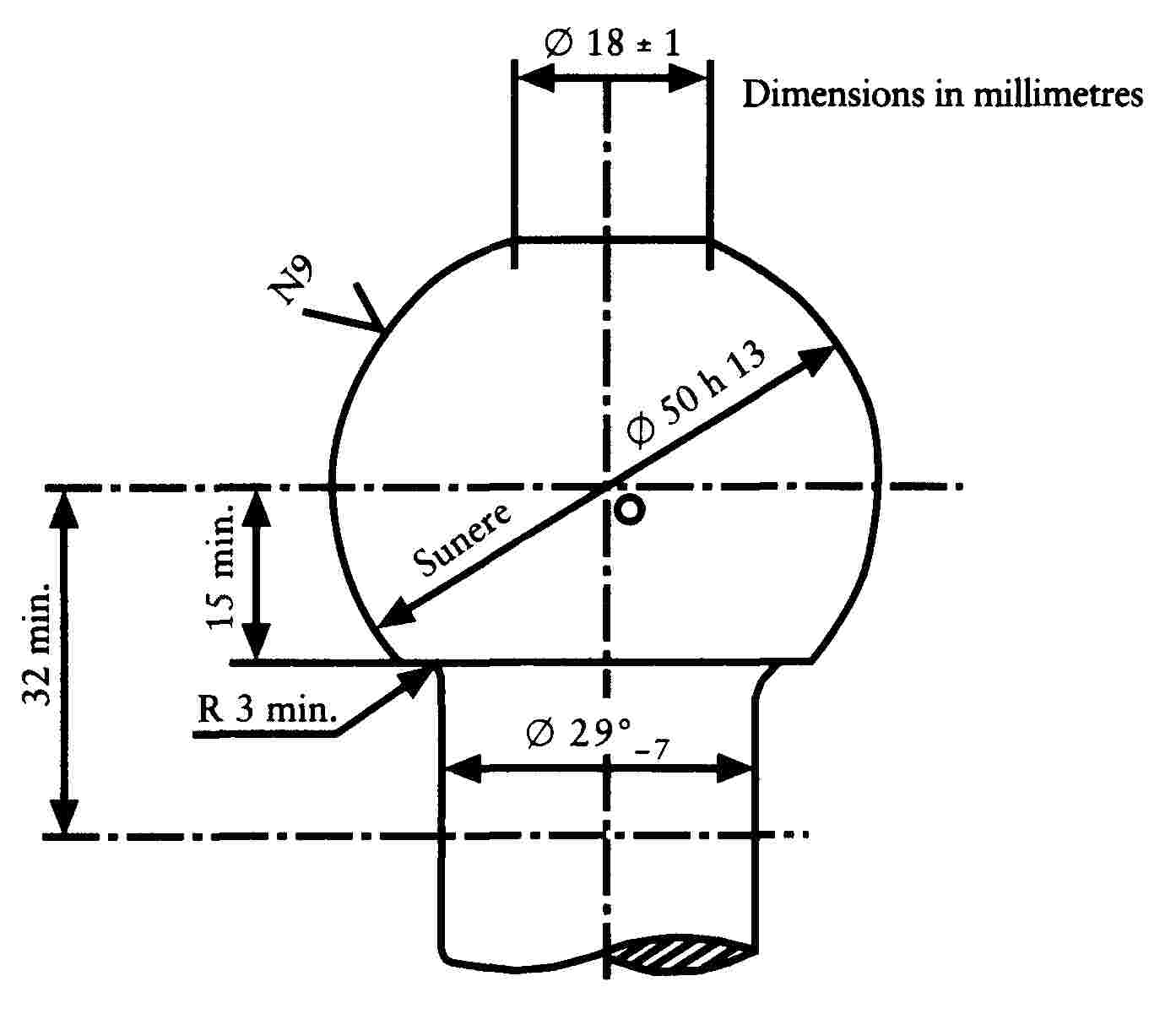
Figure 1
(1) The connecting radius between the ball and the neck is tangential both to the neck and to the lower horizontal surface of the coupling ball.
(2) See ISO/R 468 and ISO 1302; the roughness number N9 refers to an Ra value of 6,3 μm.

Figure 2
Clearance space for coupling balls
Appendix 2
The test direction is shown by the example of a coupling ball with towing bracket. (Applicable by analogy to other coupling systems).

Appendix 3
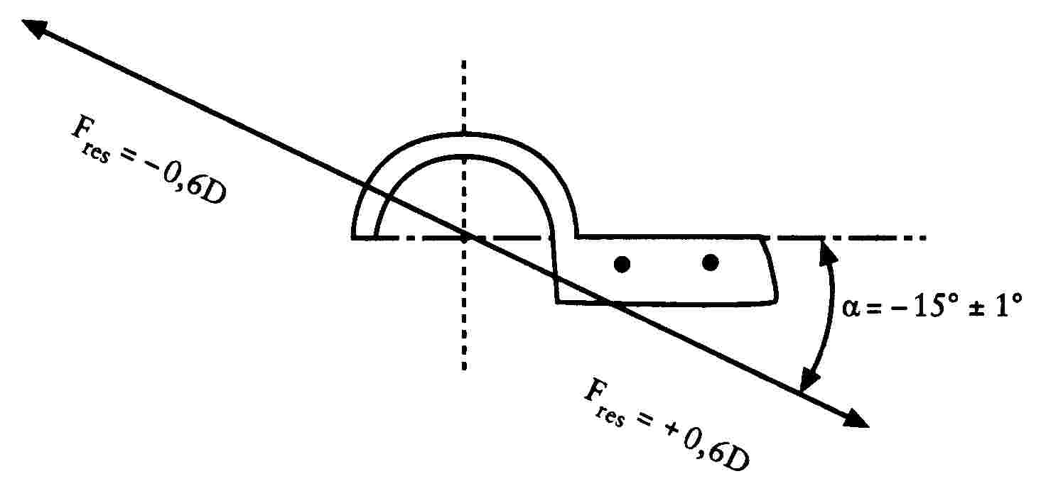
Figure 6

Figure 7
Appendix 4

Appendix 5

CHAPTER 11
SAFETY-BELT ANCHORAGES AND SAFETY-BELTS OF THREE-WHEEL MOPEDS, TRICYCLES AND QUADRICYCLES
LIST OF ANNEXES
|
ANNEX I |
Definitions |
|
ANNEX II |
Effective anchorage attachment areas |
|
ANNEX III |
Procedure to be followed in order to determine the position of the H point and the true backrest rake angle and to check their relationship with the position of the R point and the intended backrest rake angle |
|
Appendix |
Components of the three-dimensional dummy |
|
ANNEX IV |
Traction device |
|
ANNEX V |
|
|
Appendix 1 |
Information document in respect of safety-belt anchorages intended for a type of bodied three-wheel moped, tricycle or quadricyle |
|
Appendix 2 |
Component type-approval certificate in respect of safety-belt anchorages for a type of bodied three-wheel moped, tricycle or quadricycle |
|
ANNEX VI |
Requirements for safety-belts |
|
Appendix 1 |
Information document in respect of a type of safety-belt intended for bodied three-wheel mopeds, tricycles or quadricycles |
|
Appendix 2 |
Component type-approval certificate in respect of a type of safety-belt intended for bodied three-wheel mopeds, tricycles or quadricycles |
|
Appendix 3 |
Information document in respect of the fitting of safety-belts to a type of bodied three-wheel moped, tricycle or quadricycle |
|
Appendix 4 |
Component type-approval certificate in respect of the fitting of safety-belts to a type of bodied three-wheel moped, tricycle or quadricycle |
ANNEX I
1. DEFINITIONS
For the purposes of this Chapter:
|
1.1. |
‘type of vehicle in respect of its safety-belt anchorages’ means motor vehicles which do not differ in such essential respects as the following: dimensions, shapes and materials of the structural components of the vehicle or seat to which the anchorages are attached; |
|
1.2. |
‘safety-belt anchorages’ means the parts of the structures of the vehicle or seat or all other parts of the vehicle to which the belts must be fastened; |
|
1.3. |
‘strap guide’ means a device which alters the lie of the strap in relation to the wearer of the belt assembly; |
|
1.4. |
‘effective anchorage’ means the point used to determine, in a conventional manner in accordance with section 4, the angle of each part of the safety-belt in relation to its wearer i.e. the point where a strap should be attached in order to adopt a position identical to an intended position of the belt when this is used and which may or may not correspond to the true anchorage according to the configuration of the accessories for the attachment of the belt at the point where this is attached to the anchorage; 1.4.1. for example:
|
|
1.5. |
‘floor’ means the lower part of the bodywork of the vehicle linking the side walls of that vehicle. Taken within this meaning the floor includes the ribs, raised pressings and any other stiffeners even where these are beneath the floor, such as spars and struts. |
|
1.6. |
‘seat’ means a structure, whether or not forming an integral part of the vehicle structure and including its trim, which offers a seated position for an adult, the term designating both an individual seat and part of a bench corresponding to a seating position. A saddle is not considered to be a seat for item 2.1. |
|
1.6a. |
‘saddle’ means a seating position where the rider or passenger sits astride. |
|
1.7. |
‘group of seats’ means either a bench-type seat or separate seats mounted side by side (i.e. in such a way that the front anchorages of a seat are in line with or ahead of the rear anchorages of another seat and in line with or behind the front anchorages of that same other seat) providing one or several seating positions for adults. |
|
1.8. |
‘bench’ means a complete structure together with its cover which provides at least two seating positions for adult occupants. |
|
1.9. |
‘tip-up seat’ means an auxiliary seat intended for occasional use that is normally folded away; |
|
1.10. |
‘type of seat’ means a category of seats which do not differ essentially among themselves in such respects as:
|
|
1.11. |
‘seat anchorage’ means the system of attaching the seat in its entirety to the vehicle structure, including the relevant parts of the vehicle structure. |
|
1.12. |
‘adjustment system’ means the device enabling the parts of the seat to be adjusted in order to achieve a seating position that is adapted to the occupant's morphology. That adjustment device may in particular permit:
|
|
1.13. |
‘protected space’ means a space within which the screening areas within the protective space have a cumulative area of at least 800 cm2. |
|
1.14. |
‘protection space’ means the space in front of a seat and lying: — between two horizontal planes, one of which passes through the H point as defined in 1.17 and the other which is 400 mm above that point; — between vertical longitudinal planes that are symmetrical in relation to the H point and lie 400 mm apart; — behind a vertical transverse plane that is 1,30 m from the H point. In any given transverse vertical plane a continuous surface such that, if a 165 mm diameter sphere is projected in a horizontal longitudinal direction passing through any given point within the zone and through the centre of the sphere there is within the protection space no aperture through which the sphere can be passed, is called a ‘screening area’. |
|
1.15. |
‘movement system’ means a device enabling a seat or one of its parts to move or rotate without any fixed intermediate position in order to ease access to the space behind the seat concerned. |
|
1.16. |
‘locking system’ means a device holding the seat and its parts in any position of use and comprising mechanisms for locking the seat backrest in relation to the seat and the seat in relation to the vehicle. |
|
1.17. |
‘H-point’ means a reference point as defined in section 1.1 of Annex III determined in accordance with the procedure described in that Annex. |
|
1.18. |
‘H1-point’ means the reference point corresponding to the H point defined in 1.17 and determined for all normal positions of use of the seat. |
|
1.19. |
‘R-point’ means the reference point of a seat as defined in section 1.2 of Annex III. |
|
1.20. |
‘reference line’ means the straight line defined in section 3.4 of Annex III. |
|
1.21. |
‘L1 and L2-points’ means the lower effective anchorages. |
|
1.22. |
‘C-point’ means the point located 450 mm vertically above the R point. However, if distance S defined in 1.24 is not less than 280 mm and if the other conceivable formula, BR = 260 mm + 0,8 S specified in section 4.3.3 is retained by the manufacturer the vertical distance between C and R must be 500 mm. |
|
1.23. |
‘α1 and α2’ angles mean respectively the angles formed by a horizontal plane and the planes perpendicular to the median longitudinal plane of the vehicle and passing through point H1 and points L1 and L2. |
|
1.24. |
‘S’ means the distance, in millimetres, between the effective upper anchorage and a reference plane P that is parallel to the median longitudinal plane of the vehicle, defined as follows:
|
2. GENERAL REQUIREMENTS
|
2.1. |
Whenever safety belt anchorages are fitted, these must comply with the prescriptions in this Chapter.
|
3. MINIMUM NUMBER OF BELT ANCHORAGES
|
3.1. |
Two lower and one upper anchorage must be provided for the front seats. However, two lower anchorages are considered sufficient for the front centre seats, if fitted, where there are other front seats and the windscreen is located outside the reference zone defined in Annex II to Directive 74/60/EEC. The windscreen is considered as forming part of the reference zone for the anchorages should the windsceen enter into static contact with the device for testing in accordance with the method described in Annex II to Directive 74/60/EEC on the interior fittings of motor vehicles ( 75 ). |
|
3.2. |
for the outboard seats two lower anchorages and one upper anchorage must be provided. |
|
3.3. |
with the exception of the tip-up seat for which anchorages are not required, at least two lower anchorages must be provided for all other forward-facing seats. |
|
3.4. |
If the vehicle is fitted with anchorages for tip-up seats, the anchorages must comply with this Chapter. |
4. POSITIONING OF SAFETY-BELTS
(see Annex II, figure 1)
4.1. General
|
4.1.1. |
The anchorages for any one belt may all be attached to the structure of the vehicle, or of the seat or to any other part of the vehicle, or be divided among those various positions. |
|
4.1.2. |
The same anchorage may receive the ends of two adjancent belts provided that the test requirements are met. |
|
4.2. |
Position of lower effective anchorages
|
|
4.3. |
Position of the upper effective anchorages (see Annex II, figure 2)
|
5. STRENGTH OF ANCHORAGES
|
5.1. |
Each anchorage must be able to withstand the tests provided for in 6.3 and 6.4. Permanent deformation, including partial rupture of an anchorage or the surrounding area does not constitute failure if the required force is sustained for the specified time. During the test the minimum distances for the lower effective anchorages required in 4.2.3 and the requirements set out in 4.3.6 and 4.3.7 for upper effective anchorages must be maintained. |
|
5.2. |
In the vehicles in which these devices are used the movement and locking systems enabling the occupants of all the seats to exit from the vehicle must still be capable of being manually activated after the tractive force has ceased to be applied; |
|
5.3. |
Dimensions of threaded holes for anchorages The threaded holes for the anchorages must be of the 7/16-20 UNF 2 B type in accordance with ISO Standard TR 1417. |
|
5.4. |
If the manufacturer has fitted the vehicle with safety-belts that have been attached at all of the anchorages required for a particular seat, it is not necessary that those anchorages meet the requirements of 5.3 provided that they meet the other requirements of this Chapter. Moreover, the requirement set out in 5.3 does not apply to additional anchorages meeting the requirement set out in 4.3.7.3. |
|
5.5. |
It must be possible to remove the safety-belt from the anchorage without damage to the anchorage. |
6. TESTS
6.1. General
|
6.1.1. |
Subject to the implementation of the provisions set out in 6.2 and in line with the manufacturer's request,
|
|
6.1.2. |
The seats must be installed and adjusted to their driving position or position of use selected by the testing body responsible for the component type-approval tests as being the least favourable from a system-strength point of view. The position of the seats must be stated in the report. If its angle is adjustable the backrest must be locked in position in accordance with the manufacturer's instructions or, in their absence, in a position corresponding to an effective seat angle as close as possible to 15o and in the case of a quadricycle to 25o. |
6.2. Vehicle restraint
|
6.2.1. |
The method used to restrain the vehicle during the test must not cause the anchorage or anchorage areas to be reinforced or reduce the normal deformation of the structure. |
|
6.2.2. |
A restraint device is considered satisfactory if it has no effect on an area extending throughout the width of the structure and if the vehicle or structure is locked or attached at the front at a distance of at least 500 mm from the anchorage to be tested and held or attached at the rear at least 300 mm from said anchorage. |
|
6.2.3. |
It is recommended that the structure be made to rest on supports directly below the wheel axes or if that is not possible directly below the suspension points. |
6.3. General test requirements
|
6.3.1. |
All the anchorages within the same group of seats must be tested simultaneously. |
|
6.3.2. |
The tractive force must be applied forwards at an angle of 10o ± 5o above the horizontal in a plane parallel to the median longitudinal plane of the vehicle. |
|
6.3.3. |
The loading must begin as quickly as possible. The anchorages must withstand the specified load for at least 0,2 s. |
|
6.3.4. |
The traction devices to be used for the tests described in 6.4 are shown in Annex IV. |
|
6.3.5. |
The anchorages for seats fitted with upper anchorages must be tested under the following conditions:
|
|
6.3.6. |
Where there are no upper anchorages for the outboard side seats and central seats, the lower anchorages must be subjected to the test required in 6.4.3 in which the forces are transferred to them by means of a device reproducing the geometry of a lap belt. |
|
6.3.7. |
If the vehicle is designed to receive other devices which do not enable the straps to be attached directly to the anchorages without the use of intermediate rollers, etc. or which require anchorages additional to those referred to in section 3, the belt or assembly of cables, rollers, etc. representing the belt equipment must be attached by means of such a device to the anchorages on the vehicle and those anchorages subjected to the test required in 6.4 as appropriate. |
|
6.3.8. |
A test method other than those required in 6.3 may be used but its equivalence must be demonstrated. |
|
6.4. |
Specific requirements for the tests to be carried out on vehicles having an unladen mass of not more than 400 kg ( 76 ) (or 550 kg if the vehicles are to be used for the transport of goods) 6.4.1. Test in three-point belt configuration incorporating an inertia reel with reverser attached to the upper anchorage.
6.4.2. Test in three-belt configuration without inertia reel or with inertia reel on the upper anchorage.
6.4.3. Test in lap-belt configuration
6.4.4. Anchorage test, with the anchorages either all attached to the seat structure or distributed among the vehicle structure and the seat structure.
6.4.5. Test in special-type belt configuration.
|
|
6.5. |
Specific requirements for the tests to be carried out on vehicles having an unladen mass of more than 400 kg (or 550 kg if the vehicles are assigned to the transport of goods) The requirements set out in Annex I to Directive 76/115/EEC ( 77 ) concerning the specific test methods on safety-belt anchorages for motor vehicles of catergory M1 apply. |
7. CHECKING AFTER THE TESTS
Any deterioration in the anchorages and load supporting structures during the tests must be recorded after the tests.
ANNEX II
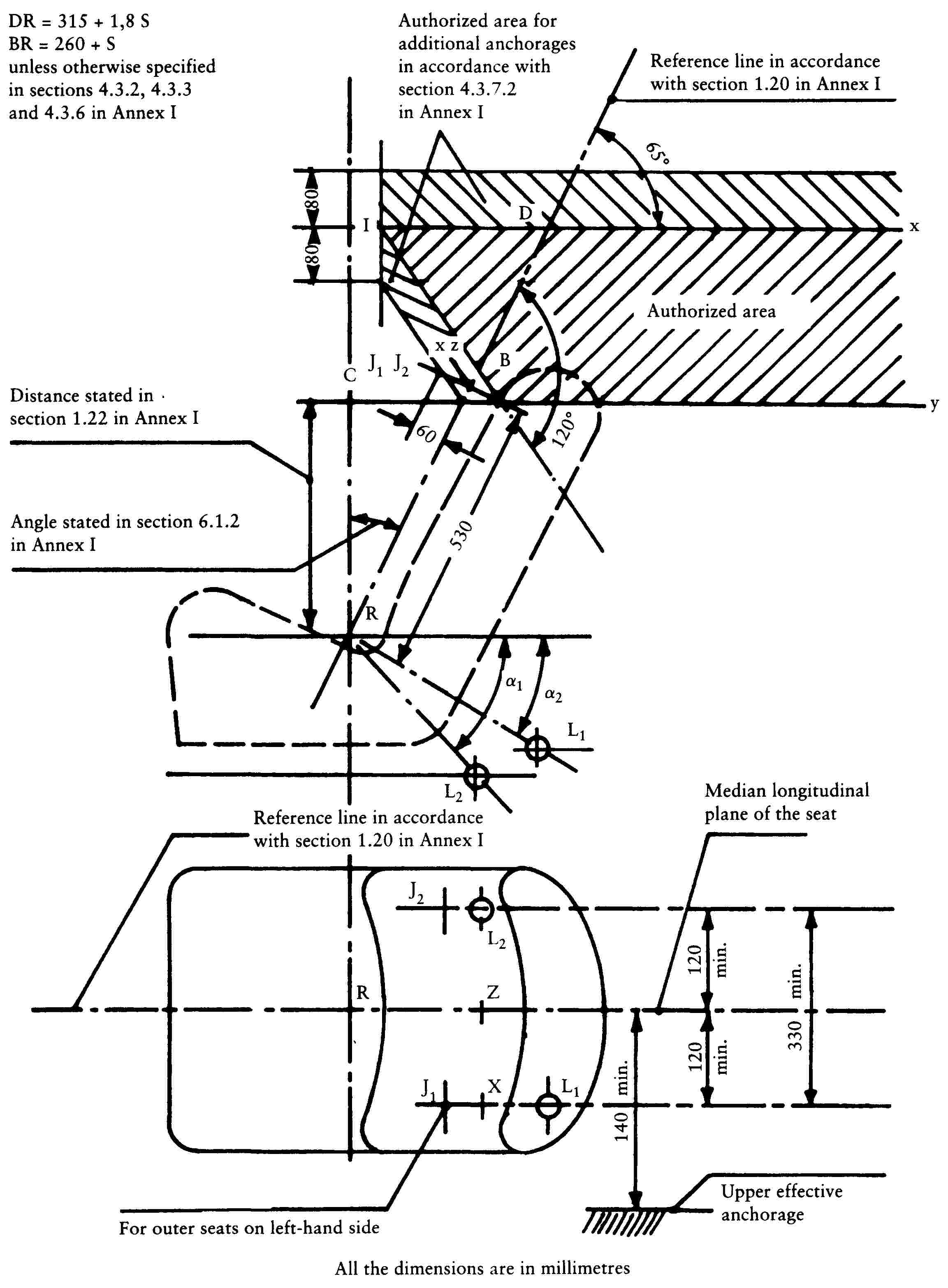
Figure 1
Effective anchorage attachment areas
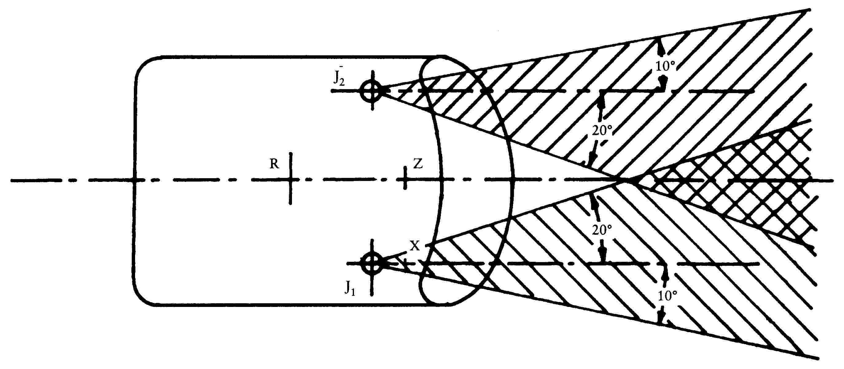
Figure 2
Effective upper anchorages in accordance with section 4.3.7.3 of Annex I
ANNEX III
PROCEDURE TO BE FOLLOWED IN ORDER TO DETERMINE THE POSITION OF THE H POINT AND THE TRUE BACKREST RAKE ANGLE AND TO CHECK THEIR RELATIONSHIP WITH THE POSITION OF THE R POINT AND THE INTENDED BACKREST RAKE ANGLE
1. DEFINITIONS
|
1.1. |
The H point which characterizes the position within the passenger compartment of a seated occupant is the trace, in a vertical longitudinal plane, of the theoretical axis of rotation between the legs and trunk of a human body, as represented by the dummy described in section 3 below. |
|
1.2. |
The R point or the ‘seated position reference point’ is the reference point stated by the manufacturer which:
|
|
1.3. |
‘Backrest rake angle’ is the inclination of the seat back in relation to the vertical. |
|
1.4. |
The ‘true backrest rake angle’ is the angle formed by the vertical line passing through the H point and the reference line for the trunk of the human body represented by the dummy described in section 3 below. |
|
1.5. |
The ‘intended backrest rake angle’ is the angle specified by the manufacturer which:
|
2. DETERMINATION OF THE H POINTS AND TRUE BACKREST RAKE ANGLES
|
2.1. |
A H point and a true backrest rake angle must be determined for each seat provided by the manufacturer. Where the seats in the same row can be regarded as similar (bench seat, identical seats, etc.), only one H point and one true backrest rake angle is determined for each row of seats, the dummy described in section 3 below being seated in a place regarded as representative for the row. This place is:
|
|
2.2. |
When a H point and a true backrest rake angle is being determined, the seat in question is placed in the rearmost normal position provided by the manufacturer for driving or travelling, the back, if adjustable, being locked in a position specified by the manufacturer or, in the absence of any specification, in a manner such that the real rake angle is between 25o and 15o. |
3. DUMMY CHARACTERISTICS
|
3.1. |
A three-dimensional dummy is used, with a mass and contour of an average-size adult. Figures 1 and 2 in the Appendix to this Annex show a diagram of this dummy. |
|
3.2. |
The dummy comprises:
|
|
3.3. |
Ballast representing the weight of each body component is located at the appropriate points constituting the corresponding centres of gravity in order to obtain a total dummy mass of approximately 75,6 kg. The details of the different ballast weights are given in Figure 2 in the Appendix. |
|
3.4. |
The reference line for the trunk of the dummy is taken into account via a straight line passing through the joint between the leg and the pelvis and the theoretical joint between the neck and thorax (see Figure 1 in the Appendix). |
4. PLACING IN POSITION OF DUMMY
The three-dimensional dummy is placed in position as follows:
|
4.1. |
The vehicle is placed on a horizontal plane and the seats adjusted as described in 2.2; |
|
4.2. |
the seat to be tested is covered with a piece of cloth intended to ease the correct placing in position of the dummy; |
|
4.3. |
the dummy is sat in the position under examination, its swivel axis being at right angles to the median longitudinal plane of symmetry of the vehicle; |
|
4.4. |
the feet of the dummy are located as follows:
|
|
4.5. |
the ballast masses are placed on the thighs, the level gauge for the transverse lean of the seat brought into the horizontal and the ballast masses placed on the component representing the seat of the dummy; |
|
4.6. |
the dummy must be moved away form the seat backrest using the knee pivot rod and its back pivoted forwards. The dummy is repositioned on the seat by sliding its seating support backwards until resistance is met, then pivoting its back rearwards until it is supported by the seat backrest; |
|
4.7. |
a horizontal force of approximately 10 ± 1 daN is then applied twice to the dummy. The direction and point of application of the force are represented by a black arrow in Figure 2 of the Appendix; |
|
4.8. |
the ballast masses are then placed on the right and left flanks, followed by the bust masses. The transverse level of the dummy must be kept horizontal; |
|
4.9. |
while the transverse level gauge of the dummy is maintained in a horizontal position the back is brought forwards until the bust masses are above the H point in such a way as to cancel out any rubbing against the seat backrest; |
|
4.10. |
the back must then be carefully moved rearwards in such a way as to complete the placing in position. The transverse level gauge for the dummy must be horizontal otherwise the above procedure must be followed again. |
5. RESULTS
|
5.1. |
Once the dummy has been placed in position in accordance with section 4, the H point and the true backrest rake angle under consideration are determined by the H point and the rake angle of the reference line of the trunk of the dummy. |
|
5.2. |
The coordinates of the H point in relation to three planes that are at right angles respectively to the true backrest rake angle must be measured for comparison with the data provided by the manufacturer of the vehicle. |
6. CHECKING OF THE POSITION RELATIVE TO THE R AND H POINTS AND OF THE RELATIONSHIP BETWEEN THE INTENDED ANGLE AND THE TRUE BACKREST RAKE ANGLE
|
6.1. |
The results of the measurements carried out in accordance with 5.2 in respect of the H point and the true backrest rake angle are compared with the coordinates for the R point and with the intended backrest rake angle stated by the manufacturer of the vehicle. |
|
6.2. |
The check on the relative position of the R and H points and on the relationship between the intended angle and true backrest rake angle is considered satisfactory for the seating position under consideration if the H point as defined by its coordinates is located within a 50 mm square having a centre R and if the true backrest rake angle does not diverge by more than 5o from the intended rake angle.
|
|
6.3. |
If the H point or the true rake angle do not meet the requirements set out in 6.2 the H point or the true rake angle are determined twice more (three times altogether). If the results obtained during two of these three operations meet the requirements the result of the test is considered satisfactory. |
|
6.4. |
If the results of at least two of the three operations do not meet the requirements set out in 6.2 the result of the test is considered unsatisfactory. |
|
6.5. |
If the situation described in 6.4 arises or if the check cannot be carried out because the manufaturer has not provided information on the position of the R point or the intended backrest rake angle the average of the results of the three determinations may be used and be considered as applying in all cases where the R point or intended backrest rake angle is referred to in this Chapter. |
Appendix

Figure 1
Components of the Three-Dimensional Dummy

Figure 2
Dimensions and mass of Dummy
ANNEX IV
TRACTION DEVICE

(dimensions in mm)
Figure 1

Figure 2
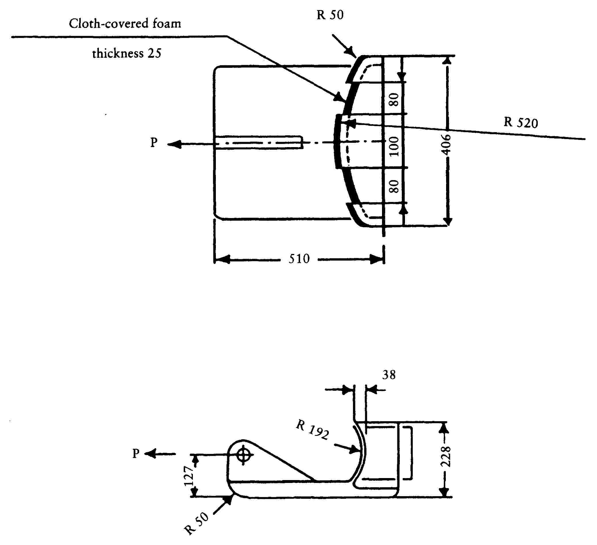
Figure 3
ANNEX V
Appendix 1

Appendix 2

ANNEX VI
REQUIREMENTS FOR SAFETY-BELTS
|
1. |
The requirements for vehicles of category M1 set out in the Annexes to Directive 77/541/EEC ( 78 ) apply. |
|
2. |
However, by way of derogation from the fitting requirements set out in section 3 of Annex I to that Directive, vehicles having an unladen mass not exceeding 400 kg (or 500 kg if the vehicles are to be used for transport of goods) may be fitted with belts or restraint systems incorporating belts that have the following configurations:
|
Appendix 1

Appendix 2

Appendix 3
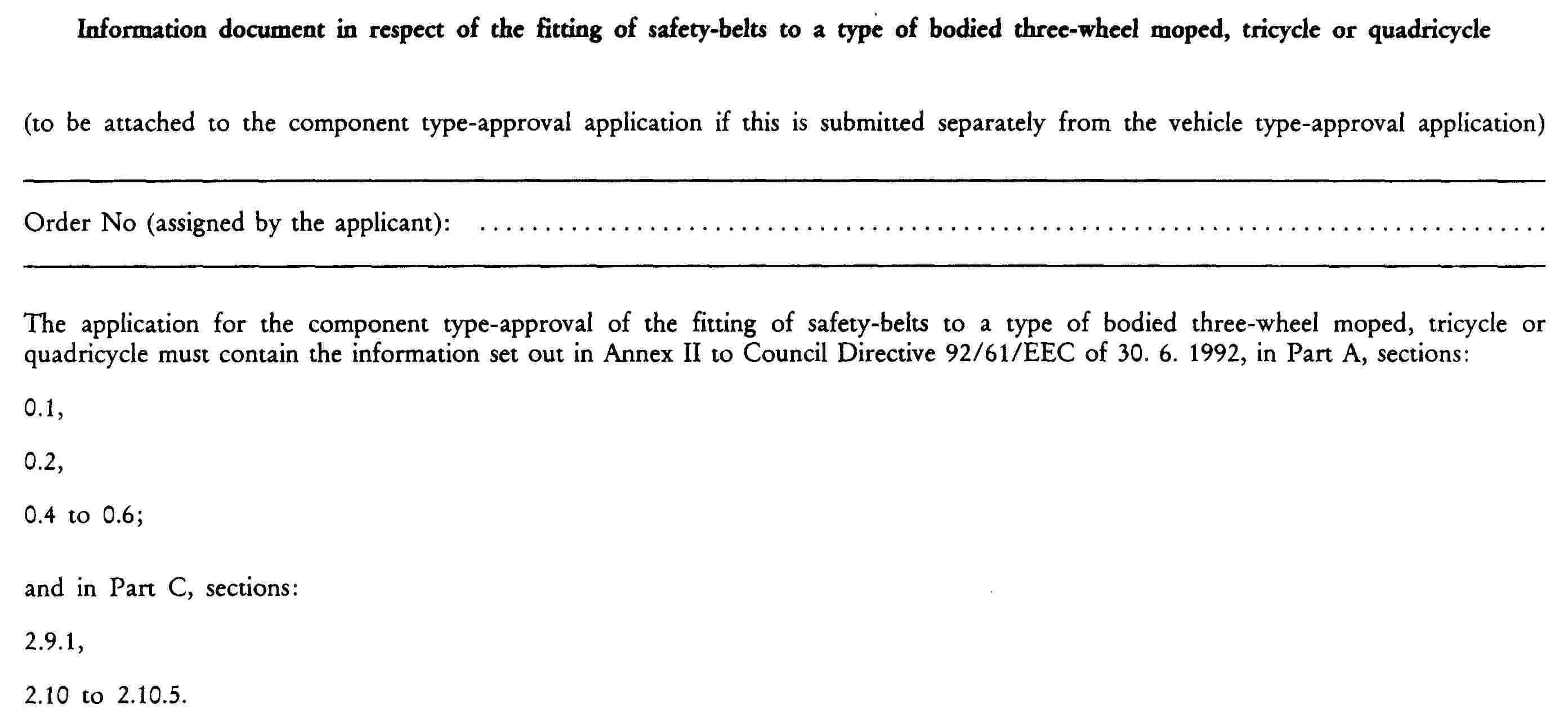
Appendix 4

CHAPTER 12
GLAZING, WINDSCREEN WIPERS, WASHERS, DE-ICERS AND DE-MISTERS OF BODIED THREE-WHEEL MOPEDS, TRICYCLES AND QUADRICYCLES
LIST OF ANNEXES
|
ANNEX I |
Glazing |
|
Appendix 1 |
Information document in respect of a type of glazing intended for bodied three-wheel mopeds, tricycles or quadricycles |
|
Appendix 2 |
Component type-approval certificate in respect of a type of glazing intended for bodied three-wheel mopeds, tricycles or quadricycles |
|
Appendix 3 |
Information document in respect of the fitting of glazing to a type of bodied three-wheel moped, tricycle or quadricycle |
|
Appendix 4 |
Component type-approval certificate in respect of the fitting of glazing to a type of bodied three-wheel moped, tricycle or quadricycle |
|
ANNEX II |
Windscreen wipers, washers and de-icers and de-misters of bodied three-wheel mopeds, tricycles or quadricycles |
|
Appendix 1 |
Procedure to be followed in order to determine the fields of vision on the windscreens of bodied three-wheel mopeds, tricycles or quadricycles in relation to the V points |
|
Appendix 2 |
Mixture for testing windscreen wipers and washers |
|
Appendix 3 |
Information document in respect of the windscreen wiper for a type of bodied three-wheel moped, tricycle or quadricycle |
|
Appendix 4 |
Component type-approval certificate in respect of the windscreen wiper for a type of bodied three-wheel moped, tricycle or quadricycle |
|
Appendix 5 |
Information document in respect of the windscreen washer for a type of bodied three-wheel moped, tricycle or quadricycle |
|
Appendix 6 |
Component type-approval certificate in respect of the windscreen washer for a type of bodied three-wheel moped, tricycle or quadricycle |
|
Appendix 7 |
Information document in respect of the de-icing and de-misting device for a type of bodied three-wheel moped, tricycle or quadricycle |
|
Appendix 8 |
Component type-approval certificate in respect of the de-icing and de-misting device for a type of bodied three-wheel moped, tricycle or quadricycle |
ANNEX I
GLAZING
For the purpose of this Chapter ‘bodied vehicle’ means a vehicle for which the passenger compartment is bounded or may be bounded by at least four of the following elements: windscreen, floor, roof, side and rear walls or doors.
1. DESIGN REQUIREMENTS
|
1.1. |
The vehicles covered by this Chapter and having a maximum design speed of more than 45 km/h are subject to the design and installation requirements set out in Directive 92/22/EEC ( 79 ) on safety glazing and glazing materials on motor vehicles and their trailers. |
|
1.2. |
The vehicles covered by this chapter and having a maximum design speed of not more than 45 km/h are subject to the requirements set out in Directive 92/22/EEC or in Annex III to Directive 89/173/EEC ( 80 ) relating to certain components and characteristics of wheeled agricultural or forestry tractors. However,
|
2. REQUIREMENTS CONCERNING THE FITTING OF WINDSCREENS AND OTHER GLAZING TO THE VEHICLES REFERRED TO IN 1.2
|
2.1. |
At the discretion of the manufacturer bodied vehicles may be fitted with:
|
Appendix 1

Appendix 2

Appendix 3
Appendix 4
ANNEX II
WINDSCREEN WIPERS, WASHERS AND DE-ICERS AND DE-MISTERS OF BODIED THREE-WHEEL MOPEDS, TRICYCLES OR QUADRICYCLES
1. DEFINITIONS
For the purposes of this Directive:
|
1.1. |
‘Type of vehicle in respect of windscreen wipers, washers, de-icers and de-misters’ means: vehicles which do not differ among themselves in such essential respects as the following:
|
|
1.2. |
‘V points’ means the points the position of which within the cab is determined by vertical longitudinal planes passing through the centres of the outermost seating positions provided on the front seat and which in relation to the R point and the intended rake of the backrest are used to check compliance with the requirements concerning fields of vision (see Appendix 1). |
|
1.3. |
R point or seating-position reference point and H point: the definitions set out in Chapter XI relating to safety-belt anchorages and safety belts apply. |
|
1.4. |
‘Windscreen reference points’ means the points on the intersection with windscreens of lines radiating forward from the V points up to the outer surface of the windscreen. |
|
1.5. |
‘Transparent area of a windscreen’ means the part of the surface the light transmission factor of which, measured at right angles to the surface, is at least 70 %. |
|
1.6. |
‘Windscreen wiper’ means the assembly consisting of a device which wipes the outer surface of the windscreen and the accessories and controls needed to start and stop the said device. |
|
1.7. |
‘Windscreen wiper field’ means the area on the outer surface of a wet windscreen that is swept by the windscreen wiper. |
|
1.8. |
‘Windscreen washer’ means a device for storing and applying a liquid to the outer surface of a windscreen, together with the necessary controls for starting and stopping the device. |
|
1.9. |
‘Windscreen washer control’ means a unit or accessory for starting and stopping the windscreen washer device. Starting and stopping may be coordinated with the operation of the windscreen wiper or be totally independent of this. |
|
1.10. |
‘Windscreen washer pump’ means a device intended to convey the windscreen washer liquid from its bottle to the surface of the windscreen. |
|
1.11. |
‘Jet’ means a device which can be directionally adjusted and which directs the screen washer liquid on to the windscreen. |
|
1.12. |
‘Operation of the windscreen washer’ means the ability of a windscreen washer device to direct the liquid on to the target area of the windscreen without producing a leak or the detachment of a windscreen washer tube when the device is used normally. |
|
1.13. |
‘De-icing device’ means a device intended to melt frost or ice from the surfaces of the windscreen and thus to restore vision. |
|
1.14. |
‘De-icing’ means the removal of the coating of frost or ice covering the glazed surfaces using the de-icing and windscreen wiping devices. |
|
1.15. |
‘De-iced area’ means the area on the glazed surfaces of which is dry or covered with melted or partly melted (damp) frost which can be removed from the outside by the windscreen wiper, but excluding the area of the windscreen that is covered with dry frost. |
|
1.16. |
‘De-misting device’ means a device intended to remove the coating of mist from the inner surface of the windscreen and thus to restore vision. |
|
1.17. |
‘Mist’ means a coating of condensate on the inner face of the glazed surfaces. |
|
1.18. |
‘De-misting’ means removal of the mist covering the glazed surfaces using the de-misting device. |
2. REQUIREMENTS
2.1. Windscreen wiper
|
2.1.1. |
All vehicles must be equipped with at least one automatic windscreen wiper i.e. which is able to operate when the engine of the vehicle is running without any intervention by the driver other than that necessary in order to start and stop the windscreen wiper.
|
|
2.1.2. |
The windscreen wiper must have a sweep frequency of at least 40 cycles per minute, a cycle being the forward and return movement of the windscreen wiper. |
|
2.1.3. |
The frequency (frequencies) referred to in 2.1.2 must be obtained as stated in 3.1.1 to 3.1.8. |
|
2.1.4. |
The wiper arm must be fitted in such a way as to be able to be folded back from the windscreen in order to enable this to be cleaned manually. |
|
2.1.5. |
The windscreen wiper must be able to operate for two minutes on a dry windscreen as required in 3.1.9. |
|
2.1.6. |
The system must be capable of withstanding stalling for a continuous period of 15 seconds, with the windscreen-wiper arms restrained in their vertical position and the windscreen-wiper control set at the maximum sweep frequency. |
2.2. Windscreen washer
|
2.2.1. |
All vehicles must be fitted with a windscreen washer able to withstand the loadings resulting from blocked jets, when the system is activated via the procedure described in 3.2.1. |
|
2.2.2. |
Operation of the screen washers and wipers must not be impaired by exposure to the temperature cycles required in 3.2.2 and 3.2.3. |
|
2.2.3. |
The windscreen washer must be able to supply enough liquid to clear 60 % of the area defined in section 2.2 of Appendix 1 under the conditions described in 3.2.4. |
|
2.2.4. |
The capacity of the liquid bottle must be at least one litre. |
2.3. De-icer and de-mister
|
2.3.1. |
All vehicles must be equipped with a windscreen de-icer and de-mister enabling any ice or frost covering the windscreen and any mist covering the inner surface of the windscreen to be removed. However, this device is not required for bodied three-wheel mopeds having an engine developing not more than 4 kW or for vehicles where the windscreen is fitted such that there is no any supporting or other structure or panel attached to the windscreen extending rearwards for more than 100 mm. The device is required for any vehicle having a roof that is either permanent or detachable or retractable. |
|
2.3.2. |
The conditions set out in 2.3.1 are considered to have been met if the vehicle is fitted with a suitable passenger-compartment heating system which must meet the conditions imposed by Directive 78/548/EEC ( 81 ) relating to heating systems for the passenger compartment of motor vehicles, with the following addendum to sections 2.4.1.1 and 2.4.1.2 of Annex I to the abovementioned Directive: ‘alternatively it must be clearly demonstrated that no leaks may reach the passenger compartment’. |
|
2.3.3. |
By way of derogation from 2.3.2 the requirements of Directive 78/317/EEC ( 82 ) relating to the defrosting and demisting systems of glazed surfaces of motor vehicles apply to vehicles having a power of more than 15 kW. |
3. TEST PROCEDURE
3.1. Windscreen wiper
|
3.1.1. |
Unless otherwise specified the tests described below must be carried out under the following conditions: |
|
3.1.2. |
The ambient temperature must not be less than 10 oC nor more than 40 oC; |
|
3.1.3. |
The windscreen must be kept constantly wet; |
|
3.1.4. |
If the windscreen wiper is electrically operated the following additional conditions must be met:
|
|
3.1.5. |
Compressed air or vacuum windscreen wipers must be able to operate continuously at the required frequencies whatever the engine speed and loading. |
|
3.1.6. |
The sweep frequencies of the windscreen wiper must meet the conditions set out in 2.1.2 following a preliminary operating period of 20 minutes on a wet surface. |
|
3.1.7. |
The outer surface of the windscreen must be thoroughly degreased with methylated spirits or an equivalent degreasing agent. After drying at least 3 % and at the most 10 % ammonia solution must be applied and allowed to dry and the surface of the windscreen then wiped with a dry cotton rag. |
|
3.1.8. |
A uniform coating of test mixture must then be applied to the outer surface of the windscreen (see Appendix 2) and then allowed to dry. |
|
3.1.9. |
The requirements of 2.1.5 must be met under the conditions specified in 3.1.4. |
3.2. Windscreen washer
Test conditions
3.2.1. Test No 1
|
3.2.1.1. |
The windscreen washer is filled with water and fully primed, then exposed to an ambient temperature of 20 ± 5 oC for a minimum of 4 hours. All of the jets are blocked and the control actuated six times within one minute, each operating period being at least 3 seconds. If the device is actuated by the muscular energy of the driver the required force is stated as in the following table:
|
|
3.2.1.2. |
The test voltage for electric pumps must not be less than the nominal voltage without, however, exceeding this by more than 2 volts. |
|
3.2.1.3. |
Once the test has been carried out the windscreen washer must operate as required in section 1.12. |
3.2.2. Test No 2 (test involving exposure to low temperatures)
|
3.2.2.1. |
The windscreen washer is filled with water, fully primed and then exposed to an ambient temperature of - 18 ± 3 oC for at least 4 hours, ensuring that all the water contained in the device is frozen. The device is then exposed to an ambient temperature of 20 ± 2 oC until the ice has completely melted. The operation of the device is then checked, and the device then actuated as required in 3.2.1. |
3.2.3. Test No 3 (exposure to high temperatures)
|
3.2.3.1. |
The windscreen washer is filled with water at a temperature of 60o ± 3 oC. The operation of the device is then checked by being actuated as required in 3.2.1. |
3.2.4. Test No 4 (windscreen washer efficiency test provided for in 2.2.3)
|
3.2.4.1. |
The windscreen washer is filled with water and fully primed. With the vehicle at a standstill and not exposed to any significant windforce the windscreen-washer jet or jets must be adjusted to point towards the target area on the outer surface of the windscreen. If the device is actuated by the muscular energy of the driver the force to be used in order to do so must not exceed that provided for in 3.2.1.1. If the device is actuated by an electric pump, the requirements of 3.1.4 apply. |
|
3.2.4.2. |
The outer surface of the windscreen is subjected to the treatment described in 3.1.7 and 3.1.8. |
|
3.2.4.3. |
The windscreen washer is then actuated as described by its manufacturer for ten automatic operating cycles of the windscreen wiper at its highest frequency and the proportion of the field of vision found in section 2.2 of Appendix 1 thus cleaned is determined. |
|
3.3. |
All the tests on the windscreen washer described in 3.2.1 to 3.2.3 must be carried out on the same device. |
Appendix 1
Procedure to be followed in order to determine the fields of vision on the windscreens of bodied three-wheel mopeds, tricycles and quadricycles in relation to the V points
1. POSITIONS OF THE V POINTS
|
1.1. |
Tables I and II give the positon of the V points in relation to the R point as emerging from their X, Y and Z coordinates within the three-dimensional reference system. |
|
1.2. |
Table I indicates the base coordinates for a designated backrest rake angle of 25o. The positive direction of the coordinates is shown in figure 1.
TABLE I
|
|
1.3. |
Correction to be made to the intended backrest rake angles other than 25o.
|
2. FIELDS OF VISION
|
2.1. |
Two fields of vision are determined from the V points. |
|
2.2. |
Field of vision A is the area on the outer protruding surface of the windscreen which is bounded by the four following planes emanating forwards from the V points (see Figure 1): — a vertical plane passing through V1 and V2 and forming an angle of 18o to the left with the X axis; — a plane parallel to the Y axis passing through V1 and forming an angle of 3o upwards with the X axis; — a plane parallel to the Y axis passing through V2 and forming an angle of 1o downwards with the X axis; — a vertical plane passing through V1 and V2 and forming an angle of 20o to the right with the X axis.
Figure 1 Field of Vision A |
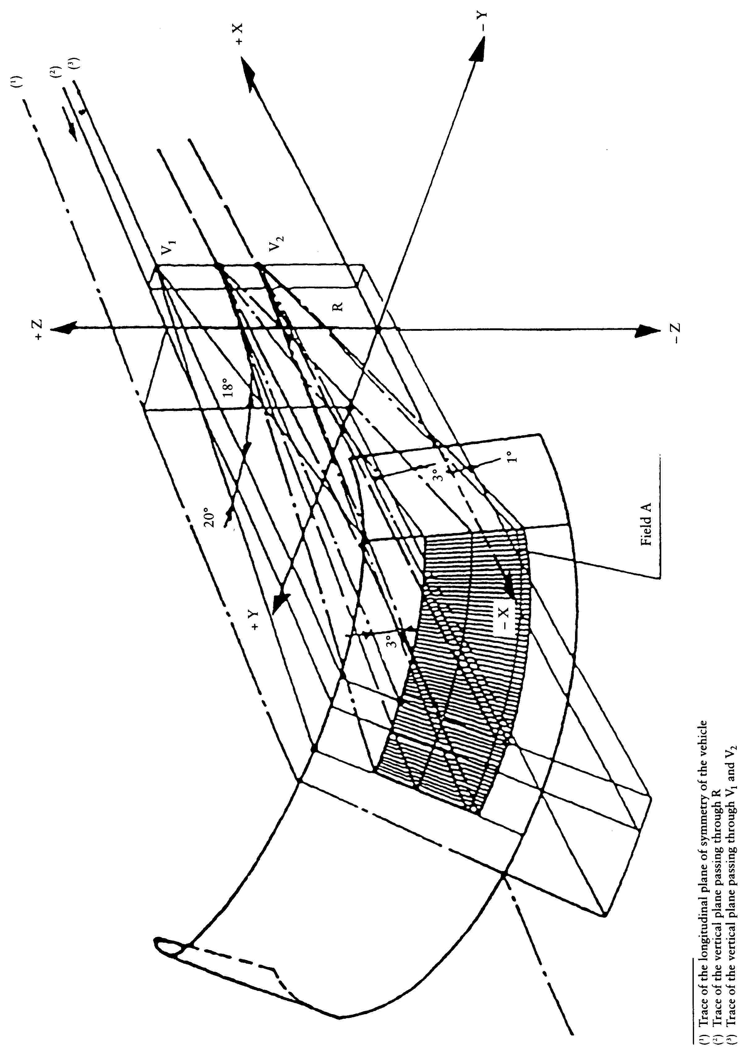
Appendix 2
Mixture for testing windscreen wipers and washers
The test mixture referred to in sections 3.1.8 and 3.2.4.2 comprises, by volume, 92.5 % of water (having a hardness of less than 205 g/1 000 kg following evaporation), 5 % of saturated aqueous salt (sodium chloride) and 2.5 % by mass of dust the composition of which is shown in Tables I and II.
TABLE I
Analysis of the test dust
|
Element |
Percentage by mass |
|
SiO2 |
67 to 69 |
|
Fe2O3 |
3 to 5 |
|
Al2O3 |
15 to 17 |
|
CaO |
2 to 4 |
|
MgO |
0,5 to 1,5 |
|
Alkalis |
3 to 5 |
|
Ignition losses |
2 to 3 |
TABLE II
Distribution of the coarse dust in accordance with the dimension of the particles
|
Particle dimension (in μm) |
Distribution according to dimension (in %) |
|
0 to 5 |
12 ± 2 |
|
5 to 10 |
12 ± 3 |
|
10 to 20 |
14 ± 3 |
|
20 to 40 |
23 ± 3 |
|
40 to 80 |
30 ± 3 |
|
80 to 200 |
9 ± 3 |
Appendix 3

Appendix 4

Appendix 5

Appendix 6
Appendix 7
Appendix 8

( 1 ) OJ No C 177, 29.6.1994, p. 1, and
OJ No C 21, 25.1.1996, p. 23.
( 2 ) OJ No C 195, 18.7.1994, p. 77.
( 3 ) Opinion of the European Parliament of 18 May 1995 (OJ No C 151, 19.6.1995, p. 184), common position of the Council of 23 November 1995 (OJ No C 190, 29.6.1996, p. 1) and Decision of the European Parliament of 19 June 1996 (OJ No C 198, 9.7.1996, p. 23). Decision of the European Parliament of 24 April 1997; Council Decision of 12 May 1997.
( 4 ) OJ No L 225, 10.8.1992, p. 72.
( 5 ) E/ECE/TRANS/505/REV 1/ADD 29.
( 6 ) E/ECE/TRANS/505/REV 1/ADD 53.
( 7 ) E/ECE/TRANS/505/REV 1/ADD 63.
( 8 ) E/ECE/TRANS/505/REV 1/ADD 74.
( 9 ) E/ECE/TRANS/324/ADD 2.
( 10 ) E/ECE/TRANS/324/REV 1/ADD 18.
( 11 ) E/ECE/TRANS/324/REV 1/ADD 19.
( 12 ) E/ECE/TRANS/505/REV 1/ADD 36.
( 13 ) E/ECE/TRANS/324/REV 1/ADD 37.
( 14 ) E/ECE/TRANS/505/REV 1/ADD 49.
( 15 ) E/ECE/TRANS/505/REV 1/ADD52/Rev.2.
( 16 ) E/ECE/TRANS/505/REV 1/ADD 55.
( 17 ) E/ECE/TRANS/505/REV 1/ADD 56.
( 18 ) E/ECE/TRANS/505/REV 1/ADD 71.
( 19 ) E/ECE/TRANS/505/REV 1/ADD73/Rev.2/Amend.1.
( 20 ) E/ECE/TRANS/505/REV 1/ADD 81.
( 21 ) E/ECE/TRANS/505/REV 1/ADD 80.
( 22 ) E/ECE/TRANS/505/REV 1/ADD 15.
( 23 ) E/ECE/TRANS/505/Rev.1/Add.40/Rev.2.
( 24 ) OJ No L 42, 23.2.1970, p. 1. Directive as last amended by Directive 96/27/EC (OJ No L 169, 8.7.1996, p. 1).
( 25 ) OJ No L 229, 30.8.1980, p. 49. Directive as last amended by Directive 80/1272/EEC (OJ No L 375, 31.12.1980, p. 73).
( 26 ) OJ No L 349, 13.12.1978, p. 21. Directive as last amended by Directive 89/235/EEC (OJ No L 98, 11.4.1989, p. 1).
( 27 ) OJ No L 139, 23.5.1989, p. 19. Directive as last amended by Directive 93/97/EEC (OJ No L 290, 24.11.1993, p. 1).
( 28 ) See diagram in Appendix 1.
( 29 ) See diagram in Appendix 1.
( 30 ) See diagram in Appendix 1.
( 31 ) The inflation pressures may also be specified as follows:
|
Tyre version |
Speed category symbol |
Pressure |
||
|
bar |
kPa |
|||
|
MOPEDS |
||||
|
standard |
B |
2,25 |
225 |
|
|
reinforced |
B |
2,80 |
280 |
|
|
MOTORCYCLES |
F, G, J, K, L, M, N, P, Q, R, S |
2,25 |
225 |
|
|
standard |
T, U, H, V, W |
2,80 |
280 |
|
|
reinforced |
F to P |
|||
|
Q, R, S, T, U, H |
3,30 |
330 |
||
|
MOTORCYCLE DERIVATIVES |
4PR |
F to M |
3,50 |
350 |
|
6PR |
4,00 |
400 |
||
|
8PR |
4,50 |
450 |
||
|
Other tyre versions must be inflated to the pressure specified by their manufacturer. |
||||
( 32 ) Headlamps of Annex III-B, III-C and III-D.
( 33 ) The measuring screen for driving on the left must be symmetrical to line v-v shown in the diagram in this Annex.
( 34 ) Technical requirements for filament lamps: see Annex IV.
( 35 ) A headlamp is regarded as satisfying the requirements of this paragraph if the filament lamp can easily be fitted into the headlamp and the positioning lugs can be correctly fitted into their slots even in darkness.
( 36 ) These provisions do not apply to the control switch.
( 37 ) The test screen must be sufficiently wide to allow examination of the cut-off over a range of at least 5o each side of the line v-v.
( 38 ) If, in the case of headlamp designed to satisfy the requirements of this Directive with respect to the passing beam only, the focal axis diverges appreciably from the general direction of the beam, or if, whatever the type of headlamp (passing only or combined passing and driving), the beam does not have a cut-off with a clear elbow, the lateral adjustment must be affected in the manner which best satisfies the requirements for illumunation at points 75 R and 50 R for right-hand traffic and at points 75 L and 50 L for left-hand traffic.
( 39 ) A headlamp designed to emit a passing beam may incorporate a driving beam not complying with this specification.
( 40 ) The limit of re-alignment of 1o towards the right or left is not incompatible with upward or downward vertical re-alignment. The latter is limited only by the requirements laid down in section 3.3; however, the horizontal part of the cut-off should not extend beyond the line h-h (the provisions of section 3.3 are not applicable to headlamps intended to meet the requirements of this Annex for passing beam only).
( 41 ) When the tested headlamp is grouped and/or reciprocally incorporated with signalling lamps, the latter must be lit for the duration of the test. In the case of a direction indicator lamp, it must be lit in flashing operation mode with an on/off time ratio of approximately one to one.
( 42 ) If two or more lamp filaments are simultaneously lit when headlamp flashing is used, this is not considered as being normal use of the filament simultaneously.
( 43 ) When the tested headlamp is grouped and/or reciprocally incorporated with signalling lamps, the latter must be lit for the duration of the test. In the case of a direction indicator lamp, it must be lit in flashing operation mode with an on/off time ratio of approximately one to one.
( 44 ) If two or more lamp filaments are simultaneously lit when headlamp flashing is used, this is not considered as being normal use of the filament simultaneously.
( 45 ) NaCMC represents the sodium salt of carboxymethylcellulose, customarily referred to as CMC. The NaCMC used in the dirt mixture must have a degree of substitution (DS) of 0,6-0,7 and a viscosity of 200-300 cP for a 2 % solution 20 oC.
( 46 ) 50 V is situated 375 mm below HV on the vertical line v-v on the screen at 25 m distance.
( 47 ) For L2 the use of a focal distance of about 80 mm is recommended.
( 48 ) The reference axis is perpendicular to the reference plane and passes through the centre of the 45 mm cap diameter.
( 49 ) The colour of the light emitted must be white.
( 50 ) No part of the cap may, by reflection of light emitted by the passing-beam filament, throw any stray rising ray when the filament lamp is in the normal operating position on the vehicle.
( 51 ) The points to be measured are those where the outside of the end turn that is nearest to or furthest from the cap crosses the filament axis.
( 52 ) The cap must be pressed in these directions.
( 53 ) See sheet H2/1.
( 54 ) The end of the filament is defined at sheet H2/3.
( 55 ) The drawing is not mandatory with respect to the design of the shield.
( 56 ) The drawing is not mandatory with respect to the design of the shield.
( 57 ) Manufacturers may choose another set of perpendicular viewing directions. The viewing directions specified by the manufacturer are to be used by the testing laboratory when checking filament dimensions and position.
( 58 ) Manufacturers may choose another set of perpendicular viewing directions. The viewing directions specified by the manufacturer are to be used by the testing laboratory when cheching filament dimensions and position.
( 59 ) OJ L 266, 2.10.1974, p. 4.
( 60 ) Definitions extracted from CIE publication 50 (45), international electrotechnical vocabulary, group 45, lighting.
( 61 ) Abridged table. The
![]()
![]()
![]()
( 62 )
![]()
![]()
where xi is any one of the individual results obtained with sample n and
![]()
![]()
( 63 ) These additional masses may where appropriate be replaced by an electronic device provided that the equivalence of the results is demonstrated.
( 64 ) UN/ECE Global Technical Regulation No 2 ‘Measurement procedure for two wheeled motorcycles equipped with a positive or compression ignition engine with regard to the emissions of gaseous pollutants, CO2 emissions and fuel consumption’ (ECE/TRANS/180/Add2 of 30 August 2005).
( 65 ) These are additional masses which may where appropriate be replaced by an electronic device, provided that the equivalence of the results is demonstrated.
( 66 ) These are additional masses which may, where appropriate, be replaced by an electronic device, provided that the equivalence of the results is demonstrated.
( 67 ) OJ L 242, 30.8.1991, p. 1.
( 68 ) The test may be performed in an air-conditioned test cell where the atmospheric conditions can be controlled.
( 69 ) OJ L 199, 28.7.2008, p. 1.
( 70 ) As provided for in this Directive in the version applicable to the type-approval of that vehicle.
( 71 ) As provided for in this Directive in the version applicable to the type-approval of that vehicle.
( 72 ) Delete as appropriate.
( 73 ) Delete as appropriate.
( 74 ) OJ No L 237, 24.8.1991, p. 1.
( 75 ) OJ No L 38, 11.2.1974, p. 2.
( 76 ) The mass of the traction batteries for electric vehicles is not included in the unladen mass.
( 77 ) OJ No L 24, 30.1.1976, p. 6.
( 78 ) OJ No L 220, 29.8.1977, p. 95.
( 79 ) OJ No L 129, 14.5.1992, p. 11.
( 80 ) OJ No L 67, 10.3.1989, p. 1.
( 81 ) OJ No L 168, 26.6.1978, p. 40.
( 82 ) OJ No L 81, 28.3.1978, p. 27.