

EUR-Lex Access to European Union law
This document is an excerpt from the EUR-Lex website
Document 02008R0692-20160101
Commission Regulation (EC) No 692/2008 of 18 July 2008 implementing and amending Regulation (EC) No 715/2007 of the European Parliament and of the Council on type-approval of motor vehicles with respect to emissions from light passenger and commercial vehicles (Euro 5 and Euro 6) and on access to vehicle repair and maintenance information (Text with EEA relevance)
Consolidated text: Commission Regulation (EC) No 692/2008 of 18 July 2008 implementing and amending Regulation (EC) No 715/2007 of the European Parliament and of the Council on type-approval of motor vehicles with respect to emissions from light passenger and commercial vehicles (Euro 5 and Euro 6) and on access to vehicle repair and maintenance information (Text with EEA relevance)
Commission Regulation (EC) No 692/2008 of 18 July 2008 implementing and amending Regulation (EC) No 715/2007 of the European Parliament and of the Council on type-approval of motor vehicles with respect to emissions from light passenger and commercial vehicles (Euro 5 and Euro 6) and on access to vehicle repair and maintenance information (Text with EEA relevance)

2008R0692 — EN — 01.01.2016 — 009.001
This document is meant purely as a documentation tool and the institutions do not assume any liability for its contents
|
COMMISSION REGULATION (EC) No 692/2008 of 18 July 2008 implementing and amending Regulation (EC) No 715/2007 of the European Parliament and of the Council on type-approval of motor vehicles with respect to emissions from light passenger and commercial vehicles (Euro 5 and Euro 6) and on access to vehicle repair and maintenance information (OJ L 199 28.7.2008, p. 1) |
Amended by:
|
|
|
Official Journal |
||
|
No |
page |
date |
||
|
L 158 |
1 |
16.6.2011 |
||
|
L 142 |
16 |
1.6.2012 |
||
|
L 182 |
14 |
13.7.2012 |
||
|
L 47 |
51 |
20.2.2013 |
||
|
L 55 |
9 |
27.2.2013 |
||
|
L 65 |
1 |
8.3.2013 |
||
|
L 158 |
74 |
10.6.2013 |
||
|
L 43 |
12 |
13.2.2014 |
||
|
L 9 |
1 |
15.1.2015 |
||
|
L 82 |
1 |
31.3.2016 |
||
Corrected by:
COMMISSION REGULATION (EC) No 692/2008
of 18 July 2008
implementing and amending Regulation (EC) No 715/2007 of the European Parliament and of the Council on type-approval of motor vehicles with respect to emissions from light passenger and commercial vehicles (Euro 5 and Euro 6) and on access to vehicle repair and maintenance information
(Text with EEA relevance)
THE COMMISSION OF THE EUROPEAN COMMUNITIES,
Having regard to the Treaty establishing the European Community, and in particular Article 95 thereof,
Having regard to Regulation (EC) No 715/2007 of the European Parliament and of the Council of 20 June 2007 on type-approval of motor vehicles with respect to emissions from light passenger and commercial vehicles (Euro 5 and Euro 6) and on access to vehicle repair and maintenance information ( 1 ), and in particular Articles 4(4), 5(3) and 8 thereof
Whereas:|
(1) |
Regulation (EC) No 715/2007 is one of the separate regulatory acts under the type-approval procedure laid down by Council Directive 70/156/EEC of 6 February 1970 on the approximation of the laws of the Member States relating to the type-approval of motor vehicles and their trailers ( 2 ). |
|
(2) |
Regulation (EC) No 715/2007 requires new light-duty vehicles to comply with new emission limits and makes additional requirements on access to information. The technical requirements take effect in two stages, Euro 5 starting from 1 September 2009 and Euro 6 from 1 September 2014. The specific technical provisions necessary to implement that Regulation should be adopted. Therefore, the present Regulation aims at setting the requirements necessary for the type-approval of Euro 5 and 6 specification vehicles. |
|
(3) |
Article 5 of Regulation (EC) No 715/2007 provides for specific technical requirements relating to the control of emissions from vehicles to be set in its implementing legislation. Therefore, it is appropriate to adopt such requirements. |
|
(4) |
Following the adoption of the main requirements for type approval in Regulation (EC) No 715/2007, it is necessary to establish administrative provisions for EC type-approval of light duty vehicles. These administrative requirements include provisions for conformity of production and in-service conformity to ensure continued good performance of production vehicles. |
|
(5) |
In accordance with Article 11 of Regulation (EC) No 715/2007, it is necessary to establish requirements for type approval of replacement pollution control devices so as to ensure that they function correctly. |
|
(6) |
In accordance with Articles 6 and 7 of Regulation (EC) No 715/2007, it is also necessary to establish requirements to ensure that vehicle on board diagnostic (OBD) and vehicle repair and maintenance information is readily accessible, so as to ensure that independent operators have access to such information. |
|
(7) |
In accordance with Regulation (EC) No 715/2007, the measures provided for in this Regulation regarding access to vehicle repair and maintenance information, information for diagnostic tools and the compatibility of replacement parts with vehicle OBD systems, should not be restricted to emissions-related components and systems but cover all aspects of a vehicle subject to type-approval within the scope of this Regulation. |
|
(8) |
As provided by Article 14(2) of Regulation (EC) No 715/2007, recalibrated limit values for particulate mass and new limit values for number of particles emitted are introduced. |
|
(9) |
The measures provided for in this Regulation are in accordance with the opinion of the Technical Committee — Motor Vehicles established by Article 40 of Directive 2007/46/EC of the European Parliament and of the Council of 5 September 2007 establishing a framework for the approval of motor vehicles and their trailers, and of systems, components and separate technical units intended for such vehicles (Framework Directive) ( 3 ). |
|
(10) |
A Forum should be established to examine any concerns raised regarding the implementation of section 2.2 of Annex XIV, concerning access information relating to vehicle security features. The information exchange in the Forum should help to reduce the risk of misuse of vehicle security information. Due to the sensitivity of the subject matter it might be necessary to keep discussions and findings of the Forum confidential. |
HAS ADOPTED THIS REGULATION:
Article 1
Subject matter
This Regulation lays down measures for the implementation of Articles 4, 5 and 8 of Regulation (EC) No 715/2007.
Article 2
Definitions
For the purposes of this Regulation, the following definitions shall apply:
1. ‘vehicle type with regard to emissions and vehicle repair and maintenance information’ means a group of vehicles which do not differ in the following respects:
(a) the equivalent inertia determined in relation to the reference mass as provided for in paragraph 5.1 of Annex 4 of UN/ECE Regulation 83 ( 4 );
(b) the engine and vehicle characteristics as set out in Appendix 3 of Annex I;
2. ‘EC type-approval of a vehicle with regard to emissions and vehicle repair and maintenance information’ means an EC type-approval of a vehicle with regard to its tailpipe emissions, crankcase emissions, evaporative emissions, fuel consumption and access to vehicle OBD and vehicle repair and maintenance information;
3. ‘gaseous pollutants’ means the exhaust gas emissions of carbon monoxide, oxides of nitrogen, expressed in nitrogen dioxide (NO2) equivalent, and hydrocarbons with the following ratio:
(a) C1H1,89O0,016 for petrol (E5);
(b) C1H1,86O0,005 for diesel (B5);
(c) C1H2,525 for liquefied petroleum gas (LPG);
(d) CH4 for natural gas (NG) and biomethane;
(e) C1H2,74O0,385 for ethanol (E85);
4. ‘starting aid’ means glow plugs, modifications to the injection timing and other devices which assist the engine to start without enrichment of the air/fuel mixture of the engine;
5. ‘engine capacity’ means either of the following:
(a) for reciprocating piston engines, the nominal engine swept volume;
(b) for rotary piston (Wankel) engines, double the nominal engine swept volume;
6. ‘periodically regenerating system’ means catalytic converters, particulate filters or other pollution control devices that require a periodical regeneration process in less than 4 000 km of normal vehicle operation
7. ‘original replacement pollution control device’ means a pollution control device or an assembly of pollution control devices whose types are indicated in Appendix 4 to Annex I to this Regulation but are offered on the market as separate technical units by the holder of the vehicle type-approval;
8. ‘type of pollution control device’ means catalytic converters and particulate filters which do not differ in any of the following essential aspects:
(a) number of substrates, structure and material;
(b) type of activity of each substrate;
(c) volume, ratio of frontal area and substrate length;
(d) catalyst material content;
(e) catalyst material ratio;
(f) cell density;
(g) dimensions and shape;
(h) thermal protection;
9. ‘mono fuel vehicle’ means a vehicle that is designed to run primarily on one type of fuel;
10. ‘mono fuel gas vehicle’ means a mono fuel vehicle that primarily runs on LPG, NG/biomethane, or hydrogen but may also have a petrol system for emergency purposes or starting only, where the petrol tank does not contain more than 15 litres of petrol;
11. ‘bi fuel vehicle’ means a vehicle with two separate fuel storage systems that can run part-time on two different fuels and is designed to run on only one fuel at a time;
12. ‘bi fuel gas vehicle’ means a bi fuel vehicle that can run on petrol and also on either LPG, NG/biomethane or hydrogen;
13. ‘flex fuel vehicle’ means a vehicle with one fuel storage system that can run on different mixtures of two or more fuels;
14. ‘flex fuel ethanol vehicle’ means a flex fuel vehicle that can run on petrol or a mixture of petrol and ethanol up to an 85 % ethanol blend (E85);
15. ‘flex fuel biodiesel vehicle’ means a flex fuel vehicle that can run on mineral diesel or a mixture of mineral diesel and biodiesel;
16. ‘hybrid electric vehicle’ (HEV) means a vehicle, including vehicles which draw energy from a consumable fuel only for the purpose of re-charging the electrical energy/power storage device, that, for the purpose of mechanical propulsion, draws energy from both of the following on-vehicle sources of stored energy/power:
(a) a consumable fuel;
(b) a battery, capacitor, flywheel/generator or other electrical energy/power storage device;
17. ‘properly maintained and used’ means, for the purpose of a test vehicle, that such a vehicle satisfies the criteria for acceptance of a selected vehicle laid down in section 2 of Appendix 1 to Annex II;
18. ‘emission control system’ means, in the context of the OBD system, the electronic engine management controller and any emission-related component in the exhaust or evaporative system which supplies an input to or receives an output from this controller;
19. ‘malfunction indicator (MI)’ means a visible or audible indicator that clearly informs the driver of the vehicle in the event of a malfunction of any emission-related component connected to the OBD system, or of the OBD system itself;
20. ‘malfunction’ means the failure of an emission-related component or system that would result in emissions exceeding the limits in section 3.3.2 of Annex XI or if the OBD system is unable to fulfil the basic monitoring requirements set out in Annex XI;
21. ‘secondary air’ means the air introduced into the exhaust system by means of a pump or aspirator valve or other means that is intended to aid in the oxidation of HC and CO contained in the exhaust gas stream;
22. ‘driving cycle’, in respect of vehicle OBD systems, consists of engine start-up, driving mode where a malfunction would be detected if present, and engine shut-off;
23. ‘access to information’ means the availability of all vehicle OBD and vehicle repair and maintenance information, required for the inspection, diagnosis, servicing or repair of the vehicle.
24. ‘deficiency’ means, in the context of the OBD system, that up to two separate components or systems which are monitored contain temporary or permanent operating characteristics that impair the otherwise efficient OBD monitoring of those components or systems or do not meet all of the other detailed requirements for OBD;
25. ‘deteriorated replacement pollution control device’ means a pollution control device as defined in Article 3(11) of Regulation (EC) No 715/2007 that has been aged or artificially deteriorated to such an extent that it fulfils the requirements laid out in Section 1 to Appendix 1 to Annex XI of UN/ECE Regulation No 83;
26. ‘vehicle OBD information’ means information relating to an on-board diagnostic system for any electronic system on the vehicle
27. ‘reagent’ means any product other than fuel that is stored on-board the vehicle and is provided to the exhaust after-treatment system upon request of the emission control system;
28. ‘mass of the vehicle in running order’ means the mass described in point 2.6 of Annex I to Directive 2007/46/EC;
29. ‘engine misfire’ means lack of combustion in the cylinder of a positive ignition engine due to absence of spark, poor fuel metering, poor compression or any other cause;
30. ‘cold start system or device’ means a system which temporarily enriches the air/fuel mixture of the engine thus assisting the engine to start;
31. ‘power take-off operation or unit’ means an engine-driven output provision for the purposes of powering auxiliary, vehicle mounted, equipment;
32. ‘small volume manufacturers’ means vehicle manufacturers whose worldwide annual production is less than 10 000 units;
33. ‘Electric power train’ means a system consisting of one or more electric energy storage devices, one or more electric power conditioning devices and one or more electric machines that convert stored electric energy to mechanical energy delivered at the wheels for propulsion of the vehicle;
34. ‘Pure electric vehicle’ means a vehicle powered by an electric power train only;
35. ‘flex fuel H2NG vehicle’ means a flex fuel vehicle that can run on different mixtures of hydrogen and NG/biomethane;
36. ‘Hydrogen fuel cell vehicle’ means a vehicle powered by a fuel cell that converts chemical energy from hydrogen into electric energy, for propulsion of the vehicle;
37. ‘net power’ means the power obtained on a test bench at the end of the crankshaft or its equivalent at the corresponding engine or motor speed with the auxiliaries, tested in accordance with Annex XX (Measurements of net engine power, net power and the maximum 30 minutes power of electric drive train), and determined under reference atmospheric conditions;
38. ‘maximum net power’ means the maximum value of the net power measured at full engine load;
39. ‘maximum 30 minutes power’ means the maximum net power of an electric drive train at DC voltage as set out in paragraph 5.3.2. of UNECE Regulation No 85 ( 5 );
40. ‘cold start’ means an engine coolant temperature (or equivalent temperature) at engine start less than or equal to 35 °C and less than or equal to 7 K higher than ambient temperature (if available) at engine start;
41. ‘Real driving emissions (RDE)’ means the emissions of a vehicle under its normal conditions of use;
42. ‘Portable emissions measurement system (PEMS)’ means a portable emissions measurement system meeting the requirements specified in Appendix 1 to Annex IIIA.
Article 3
Requirements for type-approval
1. In order to receive an EC type-approval with regard to emissions and vehicle repair and maintenance information, the manufacturer shall demonstrate that the vehicles comply with the test procedures specified in Annexes III to VIII, X to XII, XIV, XVI and XX to this Regulation. The manufacturer shall also ensure compliance with the specifications of reference fuels set out in Annex IX to this Regulation.
2. Vehicles shall be subject to the tests specified in Figure I.2.4 of Annex I.
3. As an alternative to the requirements contained in Annexes II, III, V to XI and XVI, small volume manufacturers may request the granting of EC type-approval to a vehicle type which was approved by an authority of a third country on the basis of the legislative acts set out in Section 2.1 of Annex I.
The emissions tests for roadworthiness purposes set out in Annex IV, tests fuel consumption and CO2 emissions set out in Annex XII and the requirements for access to vehicle OBD and vehicle repair and maintenance information set out in Annex XIV shall still be required to obtain EC type-approval with regard to emissions and vehicle repair and maintenance information under this paragraph.
The approval authority shall inform the Commission of the circumstances of each type approval granted under this paragraph.
4. Specific requirements for inlets to fuel tanks and electronic system security are laid down in Section 2.2 and 2.3 of Annex I.
5. The manufacturer shall take technical measures so as to ensure that the tailpipe and evaporative emissions are effectively limited, in accordance with this Regulation, throughout the normal life of the vehicle and under normal conditions of use.
These measures shall include ensuring that the security of hoses, joints and connections, used within the emission control systems, are constructed so as to conform with the original design intent.
6. The manufacturer shall ensure that the emissions test results comply with the applicable limit value under the specified test conditions of this Regulation.
7. For the Type 2 test set out in Appendix 1 to Annex IV, at normal engine idling speed, the maximum permissible carbon monoxide content in the exhaust gases shall be that stated by the vehicle manufacturer. However, the maximum carbon monoxide content shall not exceed 0,3 % vol.
At high idle speed, the carbon monoxide content by volume of the exhaust gases shall not exceed 0,2 %, with the engine speed being at least 2 000 min-1 and Lambda being 1 ± 0,03 or in accordance with the specifications of the manufacturer.
8. The manufacturer shall ensure that for the Type 3 test set out in Annex V, the engine’s ventilation system does not permit the emission of any crankcase gases into the atmosphere.
9. The Type 6 test measuring emissions at low temperatures set out in Annex VIII shall not apply to diesel vehicles.
However, when applying for type-approval, manufacturers shall present to the approval authority with information showing that the NOx aftertreatment device reaches a sufficiently high temperature for efficient operation within 400 seconds after a cold start at – 7 °C as described in the Type 6 test.
In addition, the manufacturer shall provide the approval authority with information on the operating strategy of the exhaust gas recirculation system (EGR), including its functioning at low temperatures.
This information shall also include a description of any effects on emissions.
The approval authority shall not grant type-approval if the information provided is insufficient to demonstrate that the aftertreatment device actually reaches a sufficiently high temperature for efficient operation within the designated period of time.
At the request of the Commission, the approval authority shall provide information on the performance of NOx aftertreatment devices and EGR system at low temperatures.
10. The manufacturer shall ensure that, throughout the normal life of a vehicle which is type-approved in accordance with Regulation (EC) No 715/2007, its emissions as determined in accordance with the requirements set out in Annex IIIA to this Regulation and emitted at an RDE test performed in accordance with that Annex, shall not exceed the values set out therein.
Type-approval in accordance with Regulation (EC) No 715/2007 may only be issued if the vehicle is part of a validated PEMS test family according to Appendix 7 of Annex IIIA.
Until the adoption of specific values for the parameters CFpollutan t in the table of point 2.1 of Annex IIIA to this Regulation, the following provisions shall apply:
(a) The requirements of point 2.1 of Annex IIIA to this Regulation shall only apply after the adoption of specific values for the parameters CFpollutant in the table of point 2.1 of Annex IIIA to this Regulation.
(b) The other requirements of Annex IIIA, in particular with regard to RDE tests to be performed and data to be recorded and made available, shall apply only to new type-approvals according to Regulation (EC) No 715/2007 issued after the twentieth day following that of the publication of Annex IIIA in the Official Journal of the European Union.
(c) The requirements of Annex IIIA shall not apply to type-approvals granted to small-volume manufacturers as defined in Article 2(32) of this Regulation.
(d) Where the requirements set out in Appendices 5 and 6 of Annex IIIA are satisfied for only one of the two data evaluation methods described in those Appendices, the following procedures shall be followed:
(i) one additional RDE test shall be performed;
(ii) where those requirements are again satisfied for only one method the analysis of the completeness and normality shall be recorded for both methods and the calculation required by point 9.3 of Annex IIIA may be limited to the method for which the completeness and normality requirements are satisfied.
The data of both RDE tests and of the analysis of the completeness and normality shall be recorded and made available for examining the difference in the results of the two data evaluation methods.
(e) The power at the wheels of the test vehicle shall be determined either by wheel hub torque measurement or from the CO2 mass flow using ‘Velines’ according to point 4 of Appendix 6 of Annex IIIA.
Article 4
Requirements for type-approval regarding the OBD system
1. The manufacturer shall ensure that all vehicles are equipped with an OBD system.
2. The OBD system shall be designed, constructed and installed on a vehicle so as to enable it to identify types of deterioration or malfunction over the entire life of the vehicle.
3. The OBD system shall comply with the requirements of this Regulation during conditions of normal use.
4. When tested with a defective component in accordance with Appendix 1 of Annex XI, the OBD system malfunction indicator shall be activated.
The OBD system malfunction indicator may also activate during this test at levels of emissions below the OBD thresholds limits specified in Annex XI.
5. The manufacturer shall ensure that the OBD system complies with the requirements for in-use performance set out in section 3 of Appendix 1 to Annex XI of this Regulation under all reasonably foreseeable driving conditions.
6. In-use performance related data to be stored and reported by a vehicle’s OBD system according to the provisions of point 3.6 of Appendix 1 to Annex XI shall be made readily available by the manufacturer to national authorities and independent operators without any encryption.
▼M2 —————
Article 5
Application for EC type-approval of a vehicle with regard to emissions and access to vehicle repair and maintenance information
1. The manufacturer shall submit to the approval authority an application for EC type-approval of a vehicle with regard to emissions and access to vehicle repair and maintenance information.
2. The application referred to in paragraph 1 shall be drawn up in accordance with the model of the information document set out in Appendix 3 to Annex I.
3. In addition, the manufacturer shall submit the following information:
(a) in the case of vehicles equipped with positive-ignition engines, a declaration by the manufacturer of the minimum percentage of misfires out of a total number of firing events that either would result in emissions exceeding the limits given in section 2.3 of Annex XI if that percentage of misfire had been present from the start of a type 1 test as described in Annex III to this Regulation or could lead to an exhaust catalyst, or catalysts, overheating prior to causing irreversible damage;
(b) detailed written information fully describing the functional operation characteristics of the OBD system, including a listing of all relevant parts of the emission control system of the vehicle that are monitored by the OBD system;
(c) a description of the malfunction indicator used by the OBD system to signal the presence of a fault to a driver of the vehicle;
(d) a declaration by the manufacturer that the OBD system complies with the provisions of section 3 of Appendix 1 to Annex XI relating to in-use performance under all reasonably foreseeable driving conditions;
(e) a plan describing the detailed technical criteria and justification for incrementing the numerator and denominator of each monitor that must fulfil the requirements of sections 3.2 and 3.3 of Appendix 1 to Annex XI, as well as for disabling numerators, denominators and the general denominator under the conditions outlined in section 3.7 of Appendix 1 to Annex XI;
(f) a description of the provisions taken to prevent tampering with and modification of the emission control computer;
(g) if applicable, the particulars of the vehicle family as referred to in Appendix 2 to Annex XI;
(h) where appropriate, copies of other type-approvals with the relevant data to enable extension of approvals and establishment of deterioration factors.
4. For the purposes of paragraph 3(d), the manufacturer shall use the model of a manufacturer’s certificate of compliance with the OBD in-use performance requirements set out in Appendix 7 of Annex I
5. For the purposes of paragraph 3(e), the approval authority that grants the approval shall make the information referred to in that point available to the approval authorities or the Commission upon request.
6. For the purposes of points (d) and (e) of paragraph 3, approval authorities shall not approve a vehicle if the information submitted by the manufacturer is inappropriate for fulfilling the requirements of section 3 of Appendix 1 to Annex XI.
Sections 3.2, 3.3 and 3.7 of Appendix 1 to Annex XI shall apply under all reasonably foreseeable driving conditions.
For the assessment of the implementation of the requirements set out in the first and second subparagraphs, the approval authorities shall take into account the state of technology.
7. For the purposes of paragraph 3(f), the provisions taken to prevent tampering with and modification of the emission control computer shall include the facility for updating using a manufacturer-approved programme or calibration.
8. For the tests specified in Figure I.2.4 of Annex I the manufacturer shall submit to the technical service responsible for the type-approval tests a vehicle representative of the type to be approved.
9. The application for type-approval of mono fuel, bi-fuel and flex-fuel vehicles shall comply with the additional requirements laid down in Sections 1.1 and 1.2 of Annex I.
10. Changes to the make of a system, component or separate technical unit that occur after a type-approval shall not automatically invalidate a type approval, unless its original characteristics or technical parameters are changed in such a way that the functionality of the engine or pollution control system is affected.
Article 6
Administrative provisions for EC type-approval of a vehicle with regard to emissions and access to vehicle repair and maintenance information
1. If all the relevant requirements are met, the approval authority shall grant an EC type-approval and issue a type-approval number in accordance with the numbering system set out in Annex VII to Directive 2007/46/EC.
Without prejudice to the provisions of Annex VII to Directive 2007/46/EC, section 3 of the type-approval number shall be drawn up in accordance with Appendix 6 to Annex I to this Regulation.
An approval authority shall not assign the same number to another vehicle type.
The requirements of Regulation (EC) No 715/2007 shall be deemed to be met if all the following conditions are fulfilled:
(a) the requirements of Article 3(10) are met;
(b) the requirements of Article 13 of this Regulation are met;
(c) for vehicles type-approved to the requirements of the Euro 5 emission limits given in Table 1 of Annex I of Regulation (EC) No 715/2007, the vehicle has been approved according to UN/ECE Regulations No 83, series of amendments 06, No 85, No 101, series of amendments 01 and in the case of compression ignition vehicles No 24 Part III, series of amendments 03;
(d) for vehicles type-approved to the requirements of the Euro 6 emission limits given in Table 2 of Annex I of Regulation (EC) No 715/2007, the vehicle has been approved according to UN/ECE Regulations No 83, series of amendments 07, No 85 and its supplements, No 101, Revision 3 (comprising series of amendments 01 and their supplements) and in the case of compression ignition vehicles No 24 Part III, series of amendments 03.
In the case referred to in the fourth subparagraph Article 14 shall also apply.
2. By way of derogation from paragraph 1, at the request of the manufacturer, a vehicle with an OBD system may be accepted for type-approval with regard to emissions and vehicle repair and maintenance information, even though the system contains one or more deficiencies such that the specific requirements of Annex XI are not fully met, provided that the specific administrative provisions set out in Section 3 of that Annex are complied with.
The approval authority shall notify the decision to grant such a type approval to all approval authorities in the other Member States in accordance with the requirements set out in Article 8 of Directive 2007/46/EC.
3. When granting an EC type approval under paragraph 1, the approval authority shall issue an EC type-approval certificate using the model set out in Appendix 4 to Annex I.
Article 7
Amendments to type-approvals
Articles 13, 14 and 16 of Directive 2007/46/EC shall apply to any amendments to the type-approvals.
At the manufacturer’s request the provisions specified in Section 3 of Annex I shall apply without the need for additional testing only to vehicles of the same type.
Article 8
Conformity of production
1. Measures to ensure the conformity of production shall be taken in accordance with the provisions of Article 12 of Directive 2007/46/EC.
2. Conformity of production shall be checked on the basis of the description in the type-approval certificate set out in Appendix 4 to Annex I to this Regulation.
3. The specific provisions concerning conformity of production are laid down in Section 4 of Annex I to this Regulation and the relevant statistical methods in Appendices 1 and 2 to that Annex.
Article 9
In service conformity
1. The provisions for in-service conformity are laid down in Annex II to this Regulation and, for vehicles type-approved under Council Directive 70/220/EEC ( 6 ), in Annex XV to this Regulation.
2. Measures to ensure in-service conformity of vehicles type-approved under this Regulation or Directive 70/220/EEC shall be taken in accordance with Article 12 of Directive 2007/46/EC.
3. The in-service conformity measures shall be appropriate for confirming the functionality of the pollution control devices during the normal useful life of the vehicles under normal conditions of use as specified in Annex II to this Regulation.
4. The in-service conformity measures shall be checked for a period of up to 5 years of age or 100 000 km, whichever is the sooner.
5. The manufacturer shall not be obliged to carry out an audit of in-service conformity if the number of vehicles sold precludes obtaining sufficient samples to test. Therefore, an audit shall not be required if the annual sales of that vehicle type are less than 5 000 across the Community.
However, the manufacturer of such small series vehicles shall provide the approval authority with a report of any emissions related warranty and repair claims and OBD faults as set out in point 2.3 of Annex II to this Regulation. In addition, the type-approval authority may require such vehicle types to be tested in accordance with Appendix 1 to Annex II to this Regulation.
6. With regard to vehicles type-approved under this Regulation, where the approval authority is not satisfied with the results of the tests in accordance with the criteria defined in Appendix 2 to Annex II, the remedial measures referred to in Article 30(1) and in Annex X to Directive 2007/46/EC shall be extended to vehicles in service belonging to the same vehicle type which are likely to be affected with the same defects in accordance with section 6 of Appendix 1 to Annex II.
The plan of remedial measures presented by the manufacturer according to section 6.1 of Appendix 1 of Annex II to this Regulation shall be approved by the approval authority. The manufacturer shall be responsible for the execution of the approved remedial plan.
The approval authority shall notify its decision to all Member States within 30 days. Member States may require that the same plan of remedial measures be applied to all vehicles of the same type registered in their territory.
7. If an approval authority has established that a vehicle type does not conform to the applicable requirements of Appendix 1, it shall notify without delay the Member State which granted the original type-approval in accordance with the requirements of Article 30(3) of Directive 2007/46/EC.
Following that notification and subject to the provision of Article 30(6) of Directive 2007/46/EC, the approval authority which granted the original type-approval shall inform the manufacturer that a vehicle type fails to satisfy the requirements of these provisions and that certain measures are expected of the manufacturer. The manufacturer shall submit to that authority, within two months after this notification, a plan of measures to overcome the defects, the substance of which should correspond to the requirements of sections 6.1 to 6,8 of Appendix 1. The approval authority which granted the original type-approval shall, within two months, consult the manufacturer in order to secure agreement on a plan of measures and on the carrying out the plan. If the approval authority which granted the original type-approval establishes that no agreement can be reached, the procedure pursuant to Article 30(3) and (4) of Directive 2007/46/EC shall be initiated
Article 10
Pollution control devices
1. The manufacturer shall ensure that replacement pollution control devices intended to be fitted to EC type-approved vehicles covered by the scope of Regulation (EC) No 715/2007 are EC type-approved, as separate technical units within the meaning of Article 10(2) of Directive 2007/46/EC, in accordance with Article 12, Article 13 and Annex XIII to this Regulation.
Catalytic converters and particulate filters shall be considered to be pollution control devices for the purposes of this Regulation.
The relevant requirements shall be deemed to be met if all the following conditions are fulfilled:
(a) the requirements of Article 13 are met;
(b) the replacement pollution control devices have been approved according to UN/ECE Regulation No 103.
In the case referred to in the third subparagraph Article 14 shall also apply.
2. Original equipment replacement pollution control devices, which fall within the type covered by point 2.3 of the Addendum to Appendix 4 to Annex I and are intended for fitment to a vehicle to which the relevant type-approval document refers, do not need to comply with Annex XIII provided they fulfil the requirements of points 2.1 and 2.2 of that Annex.
3. The manufacturer shall ensure that the original pollution control device carries identification markings.
4. The identification markings referred to in paragraph 3 shall comprise the following:
(a) the vehicle or engine manufacturer’s name or trade mark;
(b) the make and identifying part number of the original pollution control device as recorded in the information mentioned in point 3.2.12.2 of Appendix 3 to Annex I.
Article 11
Application for EC type-approval of a type of replacement pollution control device as a separate technical unit
1. The manufacturer shall submit to the approval authority an application for EC type-approval of a type of replacement pollution control device as a separate technical unit.
The application shall be drawn up in accordance with the model of the information document set out in Appendix 1 to Annex XIII.
2. In addition to the requirements laid down in paragraph 1, the manufacturer shall submit to the technical service responsible for the type-approval test the following:
(a) a vehicle or vehicles of a type approved in accordance with this Regulation equipped with a new original equipment pollution control device
(b) one sample of the type of the replacement pollution control device
(c) an additional sample of the type of the replacement pollution control device, in the case of a replacement pollution control device intended to be fitted to a vehicle equipped with an OBD system.
3. For the purposes of paragraph 2(a), the test vehicles shall be selected by the applicant with the agreement of the technical service.
The test vehicles shall comply with the requirements set out in Section 3.1 of Annex 4 to UN/ECE Regulation 83.
The test vehicles shall respect the following requirements:
(a) they shall have no emission control system defects;
(b) any excessively worn out or malfunctioning emission-related original part shall be repaired or replaced;
(c) they shall be tuned properly and set to manufacturer’s specification prior to emission testing.
4. For the purposes of points (b) and (c) of paragraph 2, the sample shall be clearly and indelibly marked with the applicant’s trade name or mark and its commercial designation.
5. For the purposes of paragraph 2(c), the sample shall have been deteriorated as defined under point 25 of Article 2.
Article 12
Administrative provisions for EC type-approval of replacement pollution control device as separate technical unit
1. If all the relevant requirements are met, the type approval authority shall grant an EC type-approval for replacement pollution control devices as separate technical unit and issue a type-approval number in accordance with the numbering system set out in Annex VII to Directive 2007/46/EC.
The approval authority shall not assign the same number to another replacement pollution control device type.
The same type-approval number may cover the use of that replacement pollution control device type on a number of different vehicle types.
2. For the purposes of paragraph 1, the approval authority shall issue an EC type-approval certificate established in accordance with the model set out in Appendix 2 to Annex XIII.
3. If the applicant for type-approval is able to demonstrate to the approval authority or technical service that the replacement pollution control device is of a type indicated in section 2.3 of the Addendum to Appendix 4 to Annex I, the granting of a type-approval shall not be dependent on verification of compliance with the requirements specified in section 4 of Annex XIII.
Article 13
Access to vehicle OBD and vehicle repair and maintenance information
1. Manufacturers shall put in place the neccessary arrangements and procedures, in accordance with Articles 6 and 7 of Regulation (EC) No 715/2007 and Annex XIV of this regulation, to ensure that vehicle OBD and vehicle repair and maintenance information is readily accessible.
2. Approval authorities shall only grant type-approval after receiving from the manufacturer a Certificate on Access to Vehicle OBD and Vehicle Repair and Maintenance Information.
3. The Certificate on Access to Vehicle OBD and Vehicle Repair and Maintenance Information shall serve as the proof of compliance with Article 6(7) of Regulation (EC) No 715/2007.
4. The Certificate on Access to Vehicle OBD and Vehicle Repair and Maintenance Information shall be drawn up in accordance with the model set out in Appendix 1 of Annex XIV.
5. If the vehicle OBD and vehicle repair and maintenance information is not available, or does not conform to Article 6 and 7 of Regulation (EC) No 715/2007 and Annex XIV of this Regulation, when the application for type-approval is made, the manufacturer shall provide that information within six months of the relevant date set out in paragraph 2 of Article 10 of Regulation (EC) No 715/2007 or within six months of the date of type-approval, whichever date is later.
6. The obligations to provide information within the dates specified in paragraph 5 shall apply only if, following type-approval, the vehicle is placed on the market.
When the vehicle is placed on the market more than six months after type-approval, the information shall be provided on the date on which the vehicle is placed on the market.
7. The approval authority may presume that the manufacturer has put in place satisfactory arrangements and procedures with regard to access to vehicle OBD and vehicle repair and maintenance information, on the basis of a completed Certificate on Access to Vehicle OBD and Vehicle Repair and Maintenance Information, providing that no complaint was made, and that the manufacturer provides thise information within the period set out in paragraph 5.
8. In addition to the requirements for the access to OBD information that are specified in Section 4 of Annex XI, the manufacturer shall make available to interested parties the following information:
(a) relevant information to enable the development of replacement components which are critical to the correct functioning of the OBD system.
(b) information to enable the development of generic diagnostic tools.
For the purposes of point (a), the development of replacement components shall not be restricted by: the unavailability of pertinent information, the technical requirements relating to malfunction indication strategies if the OBD thresholds are exceeded or if the OBD system is unable to fulfil the basic OBD monitoring requirements of this Regulation; specific modifications to the handling of OBD information to deal independently with vehicle operation on petrol or on gas; and the type-approval of gas-fuelled vehicles that contain a limited number of minor deficiencies.
For the purposes of point (b), where manufacturers use diagnostic and test tools in accordance with ISO 22900 Modular Vehicle Communication Interface (MVCI) and ISO 22901 Open Diagnostic Data Exchange (ODX) in their franchised networks, the ODX files shall be accessible to independent operators via the web site of the manufacturer.
9. The Forum on Access to Vehicle Information (the Forum) is hereby established.
The Forum shall consider whether access to information affects the advances made in reducing vehicle theft and shall make recommendations for improving the requirements relating to access to information. In particular, the Forum shall advise the Commission on the introduction of a process for approving and authorising independent operators by accredited organisations to access information on vehicle security.
The Commission may decide to keep the discussions and findings of the Forum confidential.
Article 14
Compliance with the obligations regarding access to vehicle OBD and vehicle repair and maintenance information
1. An approval authority may, at any time, whether on its own initiative, on the basis of a complaint, or on the basis of an assessment by a technical service, check the compliance of a manufacturer with the provisions of Regulation (EC) No 715/2007, this Regulation, and the terms of the Certificate on Access to Vehicle OBD and Vehicle Repair and Maintenance Information.
2. Where an approval authority finds that the manufacturer has failed to comply with its obligations regarding access to vehicle OBD and vehicle repair and maintenance information, the approval authority which granted the relevant type approval shall take appropriate steps to remedy the situation.
3. These steps may include withdrawal or suspension of type-approval, fines, or other measures adopted in accordance with Article 13 of Regulation (EC) No 715/2007.
4. The approval authority shall proceed to an audit in order to verify compliance by the manufacturer with the obligations concerning access to vehicle OBD and vehicle repair and maintenance information, if an independent operator or a trade association representing independent operators files a complaint to the approval authority.
5. When carrying out the audit, the approval authority may ask a technical service or any other independent expert to carry out an assessment to verify whether these obligations are met.
Article 15
Special requirements regarding type approval information
1. By way of derogation from Annex I to Council Directive 70/156/EEC ( 7 ) and until 29 April 2009, the additional requirements set out in Annex XVIII to this Regulation shall also apply.
2. By way of derogation from Annex III to Council Directive 70/156/EEC and until 29 April 2009, the additional requirements set out in Annex XIX to this Regulation shall also apply.
Article 16
Amendments to Regulation (EC) No 715/2007
Regulation (EC) No 715/2007 is amended in accordance with Annex XVII to this Regulation.
Article 17
Entry into force
This Regulation shall enter into force on the third day following its publication in the Official Journal of the European Union.
However, the obligations set out in Articles 4(5), 4(6), 5(3)(d) and 5(3)(e) shall apply from 1 September 2011 for the type-approval of new types of vehicles and from 1 January 2014 for all new vehicles sold, registered or put into service in the Community.
This Regulation shall be binding in its entirety and directly applicable in all Member States.
LIST OF ANNEXES
|
ANNEX I |
Administrative provisions for EC type-approval |
|
Appendix 1 |
Verification of conformity of production (1st statistical method) |
|
Appendix 2 |
Verification of conformity of production (2nd statistical method) |
|
Appendix 3 |
Model information document |
|
Appendix 4 |
Model EC type-approval certificate |
|
Appendix 5 |
OBD related information |
|
Appendix 6 |
EC type-approval certificate numbering system |
|
Appendix 7 |
Manufacturer's certificate of compliance with OBD in-use performance requirements |
|
ANNEX II |
In-service conformity |
|
Appendix 1 |
In-service conformity check |
|
Appendix 2 |
Statistical procedure for tailpipe emissions in-service conformity testing |
|
Appendix 3 |
Responsibilities for in-service conformity |
|
ANNEX III |
Verifying average exhaust emissions at ambient conditions (Type 1 test) |
|
ANNEX IIIA |
Verifying real driving emissions |
|
Appendix 1 |
Test procedure for vehicle emissions testing with a Portable Emissions Measurement System (PEMS) |
|
Appendix 2 |
Specifications and calibration of PEMS components and signals |
|
Appendix 3 |
Validation of PEMS and non-traceable exhaust mass flow rate |
|
Appendix 4 |
Determination of emissions |
|
Appendix 5 |
Verification of trip dynamic conditions with method 1 (Moving Averaging Window) |
|
Appendix 6 |
Verification of trip dynamic conditions with method 2 (Power Binning) |
|
Appendix 7 |
Selection of vehicles for PEMS testing at initial type approval |
|
Appendix 8 |
Data exchange and reporting requirements |
|
Appendix 9 |
Manufacturer's certificate of compliance |
|
ANNEX IV |
Emissions data required at type-approval for roadworthiness purposes |
|
Appendix 1 |
Measuring carbon monoxide emissions at idling speeds (Type 2 test) |
|
Appendix 2 |
Measurement of smoke opacity |
|
ANNEX V |
Verifying emissions of crankcase gases (Type 3 test) |
|
ANNEX VI |
Determination of evaporative emissions (Type 4 test) |
|
ANNEX VII |
Verifying the durability of pollution control devices (Type 5 test) |
|
Appendix 1 |
Standard Bench Cycle (SBC) |
|
Appendix 2 |
Standard Diesel Bench Cycle (SDBC) |
|
Appendix 3 |
Standard Road Cycle (SRC) |
|
ANNEX VIII |
Verifying the average exhaust emissions at low ambient temperatures (Type 6 test) |
|
ANNEX IX |
Specifications of reference fuels |
|
ANNEX X |
Emissions test procedure for hybrid electric vehicles (HEV) |
|
ANNEX XI |
On-board diagnostics (OBD) for motor vehicles |
|
Appendix 1 |
Functional aspects of OBD systems |
|
Appendix 2 |
Essential characteristics of the vehicle family |
|
ANNEX XII |
Determination of CO2 emissions, fuel consumption, electric energy consumption and electric range |
|
ANNEX XIII |
EC Type-approval of replacement pollution control devices as separate technical unit |
|
Appendix 1 |
Model information document |
|
Appendix 2 |
Model EC type-approval certificate |
|
Appendix 3 |
Model EC type-approval mark |
|
ANNEX XIV |
Access to vehicle OBD and vehicle repair and maintenance information |
|
Appendix 1 |
Certificate of compliance |
|
ANNEX XV |
In-service conformity of vehicles type-approval under Directive 70/220/EC |
|
Appendix 1 |
In-service conformity check |
|
Appendix 2 |
Statistical procedure for in-service conformity testing |
|
ANNEX XVI |
Requirements for vehicles that use a reagent for the exhaust aftertreatment system |
|
ANNEX XVII |
Amendments to Regulation (EC) No 715/2007 |
|
ANNEX XVIII |
Special Provisions Regarding Annex I to Council Directive 70/156/EEC |
|
ANNEX XIX |
Special Provisions Regarding Annex III to Council Directive 70/156/EEC |
|
ANNEX XX |
Measurement of net engine power |
ANNEX I
ADMINISTRATIVE PROVISIONS FOR EC TYPE-APPROVAL
1. ADDITIONAL REQUIREMENTS FOR GRANTING OF EC TYPE-APPROVAL
1.1. Additional requirements for mono fuel gas vehicles, bi-fuel gas vehicles and flex fuel H2NG vehicles.
|
1.1.1. |
For the purposes of section 1.1 the following definitions shall apply:
|
|
1.1.2. |
In case of vehicles fuelled by LPG, NG/biomethane, H2NG, EC type-approval is granted subject to the following requirements:
|


|
1.1.3. |
►M3
For the type-approval of a mono- fuel gas vehicle and bi-fuel gas vehicles operating in gas mode, fuelled by LPG or NG/biomethane, as a member of the family, a type 1 test shall be performed with one gas reference fuel. This reference fuel may be either of the gas reference fuels. The vehicle is considered to comply if the following requirements are met: ◄(a) the vehicle complies with the definition of a family member as defined in section 1.1.1.3; (b) if the test fuel is the reference fuel A for LPG or G20 for NG/Biomethane, the emission result for each pollutant shall be multiplied by the relevant factor ‘r’ calculated in section 1.1.2.4 if r > 1; if r < 1, no correction is needed; (c) if the test fuel is the reference fuel B for LPG or G25 for NG/Biomethane, the emission result for each pollutant shall be divided by the relevant factor ‘r’ calculated in section 1.1.2.4 if r < 1; if r > 1, no correction is needed; (d) on the manufacturer’s request the type 1 test may be performed on both reference fuels, so that no correction is needed; (e) the vehicle shall comply with the emission limits valid for the relevant category for both measured and calculated emissions; (f) if repeated tests are made on the same engine the results on reference fuel G20, or A, and those on reference fuel G25, or B, shall first be averaged; the ‘r’ factor shall then be calculated from these averaged results; (g) during the type 1 test the vehicle shall only use petrol for a maximum of 60 seconds when operating in gas mode. |
|
1.1.4. |
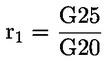
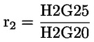
For the type-approval of a flex fuel H2NG vehicle as a member of a family, two type 1 tests shall be performed, the first test with 100 % of either G20 or G25, and the second test with the mixture of hydrogen and the same NG/biomethane fuel used during the first test, with the maximum hydrogen percentage specified by the manufacturer. The vehicle tested in accordance with the first paragraph shall be considered as complying if, in addition to requirements set out in points (a), (e) and (g) of point 1.1.3., the following requirements are met: (a) if the NG/biomethane fuel is the reference fuel G20, the emission result for each pollutant shall be multiplied by the relevant factors (r1 for the first test and r2 for the second test), calculated in section 1.1.2.5, if the relevant factor > 1; if the correspondent relevant factor < 1, no correction is needed; (b) if the NG/biomethane fuel is the reference fuel G25, the emission result for each pollutant shall be divided by the correspondent relevant factor (r1 for the first test and r2 for the second test) calculated in accordance with point 1.1.2.5, if the correspondent relevant factor < 1; if the correspondent relevant factor > 1, no correction is needed; (c) on the manufacturer's request the type 1 test must be performed with the four possible combinations of reference fuels, according to section 1.1.2.5, so that no correction is needed; (d) if repeated tests are made on the same engine the results on reference fuel G20, or H2G20, and those on reference fuel G25, or H2G25 with the maximum hydrogen percentage specified by the manufacturer, shall first be averaged; the ‘r1’ and ‘r2’ factors shall then be calculated from these averaged results. |
1.2. Additional requirements for flex fuel vehicles
|
1.2.1. |
For the type-approval of a flex fuel ethanol or biodiesel vehicle, the vehicle manufacturer shall describe the capability of the vehicle to adapt to any mixture of petrol and ethanol fuel (up to an 85 % ethanol blend) or diesel and biodiesel that may occur across the market. |
|
1.2.2. |
For flex fuel vehicles, the transition from one reference fuel to another between the tests shall take place without manual adjustment of the engine settings. |
2. ADDITIONAL TECHNICAL REQUIREMENTS AND TESTS
2.1. Small volume manufacturers
|
2.1.1. |
List of legislative acts referred to in Article 3(3):
|
2.2. Inlets to fuel tanks
|
2.2.1. |
The inlet orifice of the petrol or ethanol tank shall be designed so that it prevents the tank from being filled from a fuel pump delivery nozzle that has an external diameter of 23,6 mm or greater. |
|
2.2.2. |
Section 2.2.1 shall not apply to a vehicle for which both of the following conditions are satisfied: (a) the vehicle is designed and constructed so that no device designed to control the emission of gaseous pollutants is adversely affected by leaded petrol, and (b) the vehicle is conspicuously, legibly and indelibly marked with the symbol for unleaded petrol specified in ISO 2575:2004 in a position immediately visible to a person filling the fuel tank. Additional markings are permitted. |
|
2.2.3. |
Provision shall be made to prevent excess evaporative emissions and fuel spillage caused by a missing fuel filler cap. This may be achieved by using one of the following: (a) an automatically opening and closing, non-removable fuel filler cap, (b) design features which avoid excess evaporative emissions in the case of a missing fuel filler cap, (c) any other provision which has the same effect. Examples may include, but are not limited to, a tethered filler cap, a chained filler cap or one utilizing the same locking key for the filler cap as for the vehicle’s ignition. In this case the key shall be removable from the filler cap only in the locked condition. |
2.3. Provisions for electronic system security
|
2.3.1. |
Any vehicle with an emission control computer shall include features to prevent modification, except as authorised by the manufacturer. The manufacturer shall authorise modifications if these modifications are necessary for the diagnosis, servicing, inspection, retrofitting or repair of the vehicle. Any reprogrammable computer codes or operating parameter shall be resistant to tampering and afford a level of protection at least as good as the provisions in ISO 15031-7; dated 15 March 2001 (SAE J2186 dated October 1996). Any removable calibration memory chips shall be potted, encased in a sealed container or protected by electronic algorithms and shall not be changeable without the use of specialised tools and procedures. Only features directly associated with emissions calibration or prevention of vehicle theft may be so protected. |
|
2.3.2. |
Computer-coded engine operating parameters shall not be changeable without the use of specialized tools and procedures (e. g. soldered or potted computer components or sealed (or soldered) computer enclosures). |
|
2.3.3. |
In the case of mechanical fuel-injection pumps fitted to compression-ignition engines, manufacturers shall take adequate steps to protect the maximum fuel delivery setting from tampering while a vehicle is in service. |
|
2.3.4. |
Manufacturers may apply to the approval authority for an exemption to one of the requirements of Section 2.3 for those vehicles which are unlikely to require protection. The criteria that the approval authority shall evaluate in considering an exemption shall include the current availability of performance chips, the high-performance capability of the vehicle and the projected sales volume of the vehicle. |
|
2.3.5. |
Manufacturers using programmable computer code systems (e.g. electrical erasable programmable read-only memory, EEPROM) shall deter unauthorised reprogramming. Manufacturers shall include enhanced tamper-protection strategies and write-protect features requiring electronic access to an off-site computer maintained by the manufacturer ’, to which independent operators shall also have access using the protection afforded in Section 2.3.1. and Section 2.2. of Annex XIV. Methods giving an adequate level of tamper protection shall be approved by the approval authority. |
2.4. Application of tests
|
2.4.1. |
Figure I.2.4 illustrates the application of the tests for type-approval of a vehicle. The specific test procedures are described in Annexes II, III, IV, V, VI, VII, VIII, X, XI, XII, XVI ( 8 ) and XX.
Figure I.2.4 Application of test requirements for type-approval and extensions
Explanatory note: The dates of application of the reference fuels E10 and B7 for all new vehicles have been set out to minimise the test burden. If, however, technical evidence for vehicles certified with E5 or B5 reference fuels showing significantly higher emissions when tested with E10 or B7 is established, the Commission should make a proposal advancing these introduction dates. |
|||||||||||||||||||||||||||||||||||||||||||||||||||||||||||||||||||||||||||||||||||||||||||||||||||||||||||||||||||||||||||||||||||||||||||||||||||||||||||||||||||||||||||||||||||||||||||||||||||||||||||||||||||||||||||||||||||||||||||||||||||||||||||||||||||||||||||||||||||||||||||
3. EXTENSIONS TO TYPE-APPROVALS
3.1. Extensions for tailpipe emissions (type 1, type 2 and type 6 tests)
|
3.1.1. |
Vehicles with different reference masses
|
|
3.1.2. |
Vehicles with different overall transmission ratios
|
|
3.1.3. |
Vehicles with different reference masses and transmission ratios The type-approval shall be extended to vehicles with different reference masses and transmission ratios, provided that all the conditions prescribed in 3.1.1 and 3.1.2 are fulfilled. |
|
3.1.4. |
Vehicles with periodically regenerating systems The type-approval of a vehicle type equipped with a periodically regenerating system shall be extended to other vehicles with periodically regenerating systems, whose parameters described below are identical, or within the stated tolerances. The extension shall only relate to measurements specific to the defined periodically regenerating system.
|
|
3.1.5. |
Application of extensions to other vehicles When an extension has been granted in accordance with 3.1.1 to 3.1.4, such a type-approval shall not be further extended to other vehicles. |
3.2. Extensions for evaporative emissions (type 4 test)
|
3.2.1. |
The type-approval shall be extended to vehicles equipped with a control system for evaporative emissions which meet the following conditions:
|
|
3.2.2. |
The type-approval shall be extended to vehicles with:
|
3.3. Extensions for durability of pollution control devices (type 5 test)
|
3.3.1. |
The type-approval shall be extended to different vehicle types, provided that the vehicle, engine or pollution control system parameters specified below are identical or remain within the prescribed tolerances:
|
3.4. Extensions for on-board diagnostics
|
3.4.1. |
The type-approval shall be extended to different vehicles with identical engine and emission control systems as defined in Annex XI, Appendix 2. The type-approval shall be extended regardless of the following vehicle characteristics: (a) engine accessories; (b) tyres; (c) equivalent inertia; (d) cooling system; (e) overall gear ratio; (f) transmission type; and (g) type of bodywork. |
3.5. Extensions for CO2 emissions and fuel consumption
|
3.5.1. |
Vehicles powered by an internal combustion engine only, except vehicles equipped with a periodically regenerating emission control system.
|
|
3.5.2. |
Vehicles powered by an internal combustion engine only and equipped with a periodically regenerating emission control system
|
|
3.5.3. |
Vehicles powered by an electric power train only Extensions shall be granted after agreement with the technical service responsible for conducting the tests. |
|
3.5.4. |
Vehicles powered by a hybrid electric power train The type-approval shall be extended to vehicles differing with regard to the following characteristics, if the CO2 emissions and the electric energy consumption measured by the technical service do not exceed the type approved value by more than 4 % for vehicles of category M and 6 % for vehicles of category N: — reference mass, — technically permissible maximum laden mass, — Type of bodywork as defined in Section C of Annex II of Directive 2007/46/EC, — With respect to a change in any other characteristic extensions may be granted after agreement with the technical service responsible for conducting the tests., |
|
3.5.5. |
Extension of type-approval of vehicles of category N within a family:
|
3.6. Type-approval of vehicles of category N within a family for fuel consumption and CO2 emissions
Vehicles of category N shall be type-approved within a family as defined in point 3.6.1 using one of the two alternative methods described in points 3.6.2 and 3.6.3.
|
3.6.1. |
N vehicles may be grouped together into a family for the purposes of measurement of fuel consumption and CO2 emissions if the following parameters are identical or within the specified limits:
|
|
3.6.2. |
A vehicle family, as defined in point 3.6.1, may be approved with CO2 emission and fuel consumption data that are common to all members of the family. The technical service shall select for testing the member of the family which the service considers to have the highest CO2 emission. The measurements shall be performed as described in Annex XII, and the results according to the method described in section 5.5 of UN/ECE Regulation No 101 shall be used as type-approval values that are common to all members of the family. |
|
3.6.3. |
Vehicles that are grouped in a family as defined in point 3.6.1 may be approved with individual CO2 emission and fuel consumption data for each of the family members. The technical service shall select for testing the two vehicles, which the service considers to have the highest and the lowest CO2 emissions respectively. The measurements shall be performed as described in Annex XII. If the manufacturer’s data for these two vehicles falls within the tolerance limits described in section 5.5 of UN/ECE Regulation No 101, the CO2 emissions declared by the manufacturer for all members of the vehicle family can be used as type-approval values. If the manufacturer’s data do not fall within the tolerance limits, the results according to the method described in section 5.5 of UN/ECE Regulation No 101 shall be used as type-approval values and the technical service shall select an appropriate number of other family members for additional tests. |
4. CONFORMITY OF PRODUCTION
4.1. Introduction
|
4.1.1. |
Where applicable the tests of types 1, 2, 3, 4, the test for OBD, the test for CO2 emissions and fuel consumption and the test for smoke opacity shall be performed, as described in section 2.4. The specific procedures for conformity of production are set out in the sections 4.2 to 4.10. |
4.2. Checking the conformity of the vehicle for a type 1 test
|
4.2.1. |
The type 1 test shall be carried out on a vehicle of the same specification as described in the type-approval certificate. When a type 1 test is to be carried out for a vehicle type-approval that has one or several extensions, the type 1 tests shall be carried out either on the vehicle described in the initial information package or on the vehicle described in the information package relating to the relevant extension. |
|
4.2.2. |
After selection by the approval authority, the manufacturer shall not undertake any adjustment to the vehicles selected.
|

|
4.2.3. |
Notwithstanding the requirements of Annex III, the tests shall be carried out on vehicles coming straight off the production line.
|
4.3. Checking the conformity of the vehicle for CO2 emissions
|
4.3.1. |
If a vehicle type has had one or several extensions, the tests shall be carried out on the vehicle(s) described in the information package which accompanied the first type-approval application, or on the vehicle described in the information package that accompanied the relevant extension. |
|
4.3.2. |
If the approval authority is not satisfied with the auditing procedure of the manufacturer, points 3.3 and 3,4 of Annex X to Directive 2007/46/EC shall apply. |
|
4.3.3. |
For the purpose of this section and Appendices 1 and 2, the term ‘pollutant’ shall include the regulated pollutants (given in Tables 1 and 2 of Annex I to Regulation (EC) No 715/2007) and the emission of CO2. |
|
4.3.4. |
The conformity of the vehicle for CO2 emissions shall be determined in accordance with the procedure described in point 4.2.2. with the following exceptions:
|
|
4.3.5. |
Vehicle fitted with eco-innovations
|
4.4. Vehicles powered by an electric power train only
Measures to ensure the conformity of production with regard to electric energy consumption shall be checked on the basis of the description in the type-approval certificate set out in Appendix 4 to this Annex.
|
4.4.1. |
The holder of the approval shall, in particular:
|
|
4.4.2. |
The approval authorities may verify at any time the methods applied in each production unit.
|
4.5. Vehicles powered by a hybrid electric power train
|
4.5.1. |
Measures to ensure the conformity of production with regard to CO2 emissions and electric energy consumption from hybrid electric vehicles shall be checked on the basis of the description in the type-approval certificate conforming to the model in Appendix 4. |
|
4.5.2. |
The control of production conformity shall be based on an assessment made by the approval authority of the manufacturer’s auditing procedure in order to ensure conformity of the vehicle type with respect to the emission of CO2 and the electric energy consumption. |
|
4.5.3. |
If the approval authority is not satisfied with the standard of the manufacturer’s auditing procedure, it shall require that verification tests be carried out on vehicles in production. |
|
4.5.4. |
Conformity for CO2 emissions shall be checked using the statistical procedures described in Section 4.3 and Appendices 1 and 2. Vehicles shall be tested according to the procedure referred to in Annex XII. |
4.6. Checking the conformity of the vehicle for a type 3 test
|
4.6.1. |
If a type 3 test is to be carried out, it shall be conducted on all vehicles selected for the type 1 conformity of production test set out in section 4.2. The conditions laid down in Annex V shall apply. |
4.7. Checking the conformity of the vehicle for a type 4 test
|
4.7.1. |
If a type 4 test is to be carried out, it shall be conducted in accordance with Annex VI. |
4.8. Checking the conformity of the vehicle for On-board Diagnostics (OBD)
|
4.8.1. |
If a verification of the performance of the OBD system is to be carried out, it shall be conducted in accordance with the following requirements:
|
4.9. Checking the conformity of a vehicle fuelled by LPG, natural gas or H2NG
|
4.9.1. |
Tests for conformity of production may be performed with a commercial fuel of which the C3/C4 ratio lies between those of the reference fuels in the case of LPG, or of which the Wobbe index lies between those of the extreme reference fuels in the case of NG or H2NG. In that case a fuel analysis shall be presented to the approval authority. |
4.10. Checking the conformity of vehicle for smoke opacity
|
4.10.1. |
Conformity of the vehicle with the approved type as regards the emission of pollutants from compression ignition engines shall be verified on the basis of the results listed in the Addendum to the type-approval certificate set out in point 2.4 of Appendix 4. |
|
4.10.2. |
In addition to point 10.1, where a check is carried out on a vehicle taken from the series, the tests shall be carried out as follows: 4.10.2.1 A vehicle which has not been run in shall be subjected to the test under free acceleration described in section 4.3 of Appendix 2 to Annex IV. The vehicle shall be deemed to conform to the approved type if the absorption coefficient determined does not exceed by more than 0·5 m–1 the figure shown in the approval mark. 4.10.2.2 If the figure determined in the test referred to in point 4.10.2.1. exceeds by more than 0·5 m–1 the figure shown in the approval mark, a vehicle of the type considered or its engine shall be subjected to the test at steady speeds over the full-load curve, as described in section 4.2 of Appendix 2 to Annex IV. The emission levels shall not exceed the limits prescribed in Annex 7 to UN/ECE Regulation No 24 ( 10 ). |
Appendix 1
Verification of conformity of production — First statistical method
|
1. |
The first statistical method shall be used to verify the production conformity for the type 1 test when the manufacturer’s production standard deviation is satisfactory. The applicable statistical method is set out in Appendix 1 to UN/ECE Regulation No 83. The exceptions to these procedures are the following:
|
Appendix 2
Verification of conformity of production — Second statistical method
|
1. |
The second statistical method shall be used to verify the production conformity requirements for the type 1 test when the manufacturer’s evidence of production standard deviation is either unsatisfactory or unavailable. The applicable statistical method is set out in Appendix 2 to UN/ECE Regulation No 83, The exceptions to these procedures are the following:
|
Appendix 3
MODEL
INFORMATION DOCUMENT No …
relating to EC type-approval of a vehicle with regard to emissions and access to vehicle repair and maintenance information
The following information, if applicable, must be supplied in triplicate and include a list of contents. Any drawings must be supplied in appropriate scale and in sufficient detail on size A4 or on a folder of A4 format. Photographs, if any, must show sufficient detail.
If the systems, components or separate technical units have electronic controls, information concerning their performance must be supplied.
0. GENERAL
|
0.1. |
Make (trade name of manufacturer): |
|
0.2. |
Type:
|
|
0.3. |
Means of identification of type, if marked on the vehicle ( 11 ) ( 12 )
|
|
0.4. |
Category of vehicle ( 13 ): |
|
0.5. |
Name and address of manufacturer: |
|
0.8. |
Name(s) and address(es) of assembly plant(s): |
|
0.9. |
Name and address of the manufacturer’s representative (if any) |
1. GENERAL CONSTRUCTION CHARACTERISTICS OF THE VEHICLE
|
1.1. |
Photographs and/or drawings of a representative vehicle: |
|
1.3.3. |
Powered axles (number, position, interconnection): |
2. MASSES AND DIMENSIONS ( 14 ) (in kg and mm)
(Refer to drawing where applicable)
|
2.6. |
Mass of the vehicle with bodywork and, in the case of the towing vehicle of a category other than M1, with coupling device, if fitted by the manufacturer, in running order, or mass of the chassis or chassis with cab, without bodywork and/or coupling device if the manufacturer does not fit the bodywork and/or coupling device (including liquids, tools, spare wheel, if fitted, and driver and, for buses and coaches, a crew member if there is a crew seat in the vehicle) ( 15 ) (maximum and minimum for each variant): |
|
2.8. |
Technically permissible maximum laden mass stated by the manufacturer ( 16 ) ( 17 ) |
|
2.17. |
Vehicle submitted to multi-stage type-approval (only in the case of incomplete or completed vehicles of category N1 within the scope of Regulation (EC) No 715/2007): yes/no (17)
|
3. POWER PLANT ( 18 ) (In the case of a vehicle that can run either on petrol, diesel, etc., or also in combination with another fuel, items shall be repeated ( 19 ))
|
3.1. |
Manufacturer:
|
|
3.2. |
Internal combustion engine
|
|
3.3. |
Electric motor
|
|
3.4. |
Engines or motor combinations
|
|
3.5. |
CO2 emissions/fuel consumption ( 26 ) (manufacturer’s declared value)
▼M8 —————
|
||||||||||||||||||||||||||||||||||||||||||||||||||||||||||||||||||||||||||||||||||||||||||||||||||||||||||||||||||||||||||||||||||||||||||
|
3.6. |
Temperatures permitted by the manufacturer
|
|
3.8. |
Lubrication system
|
4. TRANSMISSION ( 35 )
|
4.3. |
Moment of inertia of engine flywheel:
|
|
4.4. |
Clutch (type):
|
|
4.5. |
Gearbox
|
|
4.6. |
Gear ratios
|
6. SUSPENSION
|
6.6. |
Tyres and wheels
|
9. BODYWORK
|
9.1. |
Type of bodywork: (use codes defined in Annex II, section C of Directive 2007/46/EC): |
|
9.10.3. |
Seats
|
16. ACCESS TO VEHICLE REPAIR AND MAINTENANCE INFORMATION
|
16.1. |
Address of principal website for access to vehicle repair and maintenance information:
|
|
16.2. |
Terms and conditions of access to website referred to in Section 16.1: |
|
16.3. |
Format of vehicle repair and maintenance information accessible through website referred to in Section 16.1: |
Appendix to information document
INFORMATION ON TEST CONDITIONS
1. Spark plugs
|
1.1. |
Make: |
|
1.2. |
Type: |
|
1.3. |
Spark-gap setting: |
2. Ignition coil
|
2.1. |
Make: …. |
|
2.2. |
Type: |
3. Lubricant used
|
3.1. |
Make: |
|
3.2. |
Type: (state percentage of oil in mixture if lubricant and fuel mixed) |
4 Dynamometer load setting information (repeat information for each dynamometer test)
|
4.1. |
Vehicle bodywork type (variant/version) |
|
4.2. |
Gearbox type (manual/automatic/CVT) |
|
4.3. |
Fixed load curve dynamometer setting information (if used)
|
|
4.4. |
Adjustable load curve dynamometer setting information (if used)
|
Appendix 4
MODEL OF EC TYPE-APPROVAL CERTIFICATE
(Maximum format: A4 (210 × 297 mm))
EC TYPE-APPROVAL CERTIFICATE
Communication concerning the:
— EC type-approval ( 36 ),
— extension of EC type-approval (36) ,
— refusal of EC type-approval (36) ,
— withdrawal of EC type-approval (36) ,
— of a type of system/type of a vehicle with regard to a system (36) with regard to Regulation (EC) No 715/2007 ( 37 ) and Regulation (EC) No 692/2008 ( 38 )
EC type-approval number:
Reason for extension:
SECTION I
|
0.1. |
Make (trade name of manufacturer): |
|
0.2. |
Type:
|
|
0.3. |
Means of identification of type if marked on the vehicle ( 39 )
|
|
0.4. |
Category of vehicle ( 40 ) |
|
0.5. |
Name and address of manufacturer: |
|
0.8. |
Name(s) and address(es) of assembly plant(s): |
|
0.9. |
Representative of the manufacturer: …. |
SECTION II
|
1. |
Additional information (where applicable): (see addendum) |
|
2. |
Technical service responsible for carrying out the tests: |
|
3. |
Date of test report: |
|
4. |
Number of test report: |
|
5. |
Remarks (if any): (see addendum) |
|
6. |
Place: |
|
7. |
Date: |
|
8. |
Signature: |
|
Attachments: |
Information package. Test report. |
Addendum to EC type-approval certificate No …
concerning the type-approval of a vehicle with regard to emissions and access to vehicle repair and maintenance information according to Regulation (EC) No 715/2007
1. Additional information
|
1.1. |
Mass of the vehicle in running order: |
|
1.2. |
Maximum mass: |
|
1.3. |
Reference mass: |
|
1.4. |
Number of seats: |
|
1.6. |
Type of bodywork:
|
|
1.7. |
Drive wheels: front, rear, 4 x 4 (41) |
|
1.8. |
Pure electric vehicle: yes/no (41) |
|
1.9. |
Hybrid electric vehicle: yes/no (41)
|
|
1.10. |
Engine identification:
|
|
1.11. |
Power train (for pure electric vehicle or hybrid electric vehicle) (41)
|
|
1.12. |
Traction battery (for pure electric vehicle or hybrid electric vehicle)
|
|
1.13. |
Transmission: …,
|
|
1.14. |
Tyres: …, , … Type: … Dimensions: Rolling circumference under load: Rolling circumference of tyres used for the Type 1 test |
2. Test results
|
2.1. |
Tailpipe emissions test results Emissions classification: Euro 5/Euro 6 (41) Type 1 test results, where applicable Type approval number if not parent vehicle (41) :
Information about regeneration strategy D — number of operating cycles between 2 cycles where regenerative phases occur: d — number of operating cycles required for regeneration: Type 2: % Type 3: Type 4: g/test
|
|||||||||||||||||||||||||||||||||||||||||||||||||||||||||||||||||||||||||||||||||||||||||||||||||||||||||||||||||||||||||||||||||||||||
|
2.2. |
Emissions data required for roadworthiness testing
|
|
2.3. |
Catalytic converters yes/no (43)
|
|
2.4. |
Smoke opacity test results (43)
|
|
2.5. |
CO2 emissions and fuel consumption test results
|
|
2.6. |
Test results of eco-innovations (
46
) (
47
)
2.6.1. General code of the eco-innovation(s) ( 48 ): … |
||||||||||||||||||||||||||||||||||||||||||||||||
|
3. |
Vehicle repair information
|
|
4. |
Power measurement Maximum engine net power of internal combustion engine, net power and maximum 30 minutes power of electric drive train 4.1. Internal combustion engine net power
4.2. Electric drive train(s):
|
|
5. |
Remarks: |
Appendix 5
Vehicle OBD information
|
1. |
The information required in this Appendix shall be provided by the vehicle manufacturer for the purposes of enabling the manufacture of OBD-compatible replacement or service parts and diagnostic tools and test equipment. |
|
2. |
Upon request, the following information shall be made available to any interested component, diagnostic tools or test equipment manufacturer, on a non-discriminatory basis:
|
|
3. |
Information required for the manufacture of diagnostic tools In order to facilitate the provision of generic diagnostic tools for multi-make repairers, vehicle manufacturers shall make available the information referred to in the points 3.1 to 3.3. through their repair information web-sites. This information shall include all diagnostic tool functions and all the links to repair information and troubleshooting instructions. The access to this information may be subject to the payment of a reasonable fee. 3.1. Communication Protocol Information The following information shall be required indexed against vehicle make, model and variant, or other workable definition such as VIN or vehicle and systems identification: (a) Any additional protocol information system necessary to enable complete diagnostics in addition to the standards prescribed in Annex XI Section 4, including any additional hardware or software protocol information, parameter identification, transfer functions, ‘keep alive’ requirements, or error conditions; (b) Details of how to obtain and interpret all fault codes not in accordance with the standards prescribed in Annex XI Section 4: (c) A list of all available live data parameters including scaling and access information; (d) A list of all available functional tests including device activation or control and the means to implement them; (e) Details of how to obtain all component and status information, time stamps, pending DTC and freeze frames; (f) Resetting adaptive learning parameters, variant coding and replacement component setup, and customer preferences; (g) ECU identification and variant coding; (h) Details of how to reset service lights; (i) Location of diagnostic connector and connector details; (j) Engine code identification. 3.2. Test and diagnosis of OBD monitored components The following information shall be required: (a) A description of tests to confirm its functionality, at the component or in the harness (b) Test procedure including test parameters and component information (c) Connection details including minimum and maximum input and output and driving and loading values (d) Values expected under certain driving conditions including idling (e) Electrical values for the component in its static and dynamic states (f) Failure mode values for each of the above scenarios (g) Failure mode diagnostic sequences including fault trees and guided diagnostics elimination. 3.3. Data required to perform the repair The following information shall be required: (a) ECU and component initialisation (in the event of replacements being fitted) (b) Initialisation of new or replacement ECU’s where relevant using pass-through (re-) programming techniques. |
Appendix 6
EC Type –Approval Certification Numbering System
|
1. |
Section 3 of the EC type-approval number issued according to Article 6(1) shall be composed by the number of the implementing regulatory act or the latest amending regulatory act applicable to the EC type-approval. ►M2 This number shall be followed by one or more characters reflecting the different categories in accordance with Table 1. ◄ These alphabetical characters shall also distinguish the Euro 5 and 6 emission limit values to which the approval was granted.
Table 1
|
||||||||||||||||||||||||||||||||||||||||||||||||||||||||||||||||||||||||||||||||||||||||||||||||||||||||||||||||||||||||||||||||||||||||||||||||||||||||||||||||||||||||||||||||||||||||||||||||||||||||||||||||||||||||||||||||||||||||||||||||||||||||||||||||||||||||||||||||||||||||||||||||
|
2. |
Examples of type–approval certification numbers.
|
Appendix 7

ANNEX II
IN-SERVICE CONFORMITY
1. INTRODUCTION
|
1.1. |
This Annex sets out the tailpipe emissions and OBD (inclusive IUPRM) in-service conformity requirements for vehicles type approved to this Regulation. |
2. AUDIT OF IN-SERVICE CONFORMITY
|
2.1. |
The audit of in-service conformity by the approval authority shall be conducted on the basis of any relevant information that the manufacturer has, under the same procedures as those for the conformity of production defined in Article 12(1) and (2) of Directive 2007/46/EC and in points 1 and 2 of Annex X to that Directive. Information from approval authority and Member State surveillance testing may complement the in-service monitoring reports supplied by the manufacturer. |
|
2.2. |
The figure referred to in point 9 of Appendix 2 to this Annex and Figure 4/2 of Appendix 4 to UN/ECE Regulation No 83 (for tailpipe emissions only) illustrates the procedure for in-service conformity checking. The process for in-service conformity is described in Appendix 3 to this Annex. |
|
2.3. |
As part of the information provided for the in-service conformity control, at the request of the approval authority, the manufacturer shall report to the type-approval authority on warranty claims, warranty repair works and OBD faults recorded at servicing, according to a format agreed at type-approval. The information shall detail the frequency and substance of faults for emissions-related components and systems. The reports shall be filed at least once a year for each vehicle model for the duration of the period defined in Article 9(4) of this Regulation. |
|
2.4. |
Parameters defining the tailpipe emissions in-service family
The in-service family may be defined by basic design parameters which shall be common to vehicles within the family. Accordingly, vehicle types may be considered as belonging to the same in-service family if they have in common, or within the stated tolerances, the following parameters: 2.4.1. combustion process (two stroke, four stroke, rotary); 2.4.2. number of cylinders; 2.4.3. configuration of the cylinder block (in-line, V, radial, horizontally opposed, other. The inclination or orientation of the cylinders is not a criteria); 2.4.4. method of engine fuelling (e.g. indirect or direct injection); 2.4.5. type of cooling system (air, water, oil); 2.4.6. method of aspiration (naturally aspirated, pressure charged); 2.4.7. fuel for which the engine is designed (petrol, diesel, NG, LPG, etc.). Bi fuelled vehicles may be grouped with dedicated fuel vehicles providing one of the fuels is common; 2.4.8. type of catalytic converter (three-way catalyst, lean NOx trap, SCR, lean NOx catalyst or other(s)); 2.4.9. type of particulate trap (with or without); 2.4.10. exhaust gas recirculation (with or without, cooled or non-cooled); and 2.4.11. engine cylinder capacity of the largest engine within the family minus 30 %. |
|
2.5. |
Information requirements
An audit of in-service conformity will be conducted by the approval authority on the basis of information supplied by the manufacturer. Such information shall include in particular, the following: 2.5.1. the name and address of the manufacturer; 2.5.2. the name, address, telephone and fax numbers and e-mail address of his authorised representative within the areas covered by the manufacturer’s information; 2.5.3. the model name(s) of the vehicles included in the manufacturer’s information; 2.5.4. where appropriate, the list of vehicle types covered within the manufacturer’s information, i.e. for tailpipe emissions, the in-service family group in accordance with point 2.4, and for OBD and IUPRM, the OBD family in accordance with Appendix 2 to Annex XI; 2.5.5. the vehicle identification number (VIN) codes applicable to these vehicle types within the family (VIN prefix); 2.5.6. the numbers of the type-approvals applicable to these vehicle types within the family, including, where applicable, the numbers of all extensions and field fixes/recalls (re-works); 2.5.7. details of extensions, field fixes/recalls to those type-approvals for the vehicles covered within the manufacturer’s information (if requested by the approval authority); 2.5.8. the period of time over which the manufacturer’s information was collected; 2.5.9. the vehicle build period covered within the manufacturer’s information (e.g. vehicles manufactured during the 2007 calendar year); 2.5.10. the manufacturer’s in-service conformity checking procedure, including: (i) vehicle location method; (ii) vehicle selection and rejection criteria; (iii) test types and procedures used for the programme; (iv) the manufacturer’s acceptance/rejection criteria for the family group; (v) geographical area(s) within which the manufacturer has collected information; (vi) sample size and sampling plan used; 2.5.11. the results from the manufacturer’s in-service conformity procedure, including: (i) identification of the vehicles included in the programme (whether tested or not). The identification shall include the following: — model name, — vehicle identification number (VIN), — vehicle registration number, — date of manufacture, — region of use (where known), — tyres fitted (tailpipe emissions only); (ii) the reason(s) for rejecting a vehicle from the sample; (iii) service history for each vehicle in the sample (including any re-works); (iv) repair history for each vehicle in the sample (where known); (v) test data, including the following: — date of test/download, — location of test/download, — distance indicated on vehicle odometer; (vi) test data for tailpipe emissions only: — test fuel specifications (e.g. test reference fuel or market fuel), — test conditions (temperature, humidity, dynamometer inertia weight), — dynamometer settings (e.g. power setting), — test results (from at least three different vehicles per family); (vii) test data for IUPRM only: — all required data downloaded from the vehicle, — For each monitor to be reported the in-use-performance ratio IUPRM; 2.5.12. records of indication from the OBD system; 2.5.13. for IUPRM sampling, the following: — The average of in-use-performance ratios IUPRM of all selected vehicles for each monitor according to points 3.1.4 and 3.1.5 of Appendix 1 to Annex XI, — The percentage of selected vehicles, which have an IUPRM greater or equal to the minimum value applicable to the monitor according to points 3.1.4 and 3.1.5 of Appendix 1 to Annex XI. |
3. SELECTION OF VEHICLES FOR IN-SERVICE CONFORMITY
|
3.1. |
The information gathered by the manufacturer shall be sufficiently comprehensive to ensure that in-service performance can be assessed for normal conditions of use. The manufacturer’s sampling shall be drawn from at least two Member States with substantially different vehicle operating conditions (unless only sold in one Member State). Factors such as differences in fuels, ambient conditions, average road speeds, and urban/highway driving split shall be taken into consideration in the selection of the Member States. For OBD IUPRM testing only vehicles fulfilling the criteria of point 2.2.1 of Appendix 1 shall be included in the test sample. |
|
3.2. |
In selecting the Member States for sampling vehicles, the manufacturer may select vehicles from a Member State that is considered to be particularly representative. In this case, the manufacturer shall demonstrate to the approval authority which granted the type approval that the selection is representative (e.g. by the market having the largest annual sales of a vehicle family within the Union). When a family requires more than one sample lot to be tested as defined in point 3.5, the vehicles in the second and third sample lots shall reflect different vehicle operating conditions from those selected for the first sample. |
|
3.3. |
The emissions testing may be done at a test facility which is located in a different market or region from where the vehicles have been selected. |
|
3.4. |
The in-service tailpipe emissions conformity tests by the manufacturer shall be continuously carried out reflecting the production cycle of applicable vehicles types within a given in-service vehicle family. The maximum time period between commencing two in-service conformity checks shall not exceed 18 months. In the case of vehicle types covered by an extension to the type-approval that did not require an emissions test, this period may be extended up to 24 months. |
|
3.5. |
Sample size
3.5.1. When applying the statistical procedure defined in Appendix 2 (i.e. for tailpipe emissions), the number of sample lots shall depend on the annual sales volume of an in-service family in the Union, as defined in the following table:
3.5.2. For IUPR, the number of sample lots to be taken is described in the table in point 3.5.1 and is based on the number of vehicles of an OBD family that are approved with IUPR (subject to sampling). For the first sampling period of an OBD family, all of the vehicle types in the family that are approved with IUPR shall be considered to be subject to sampling. For subsequent sampling periods, only vehicle types which have not been previously tested or are covered by emissions approvals that have been extended since the previous sampling period shall be considered to be subject to sampling. For families consisting of fewer than 5 000 EU registrations that are subject to sampling within the sampling period the minimum number of vehicles in a sample lot is six. For all other families, the minimum number of vehicles in a sample lot to be sampled is fifteen. Each sample lot shall adequately represent the sales pattern, i.e. at least high volume vehicle types (≥ 20 % of the family total) shall be represented. |
|
4. |
On the basis of the audit referred to in Section 2 the approval authority shall adopt one of the following decisions and actions: (a) decide that the in-service conformity of a vehicle type, vehicle in-service family or vehicle OBD family is satisfactory and not take any further action; (b) decide that the data provided by the manufacturer is insufficient to reach a decision and request additional information or test data from the manufacturer; (c) decide that based on data from the approval authority or Member State surveillance testing programmes, that information provided by the manufacturer is insufficient to reach a decision and request additional information or test data from the manufacturer; (d) decide that the in-service conformity of a vehicle type, that is part of an in-service family, or of an OBD family, is unsatisfactory and proceed to have such vehicle type or OBD family tested in accordance with Appendix 1. If according to the IUPRM audit the test criteria of point 6.1.2 point (a) or (b) of Appendix 1 are met for the vehicles in a sample lot, the type-approval authority must take the further action described in point (d) of this point.
|
Appendix 1
In-service conformity check
1. INTRODUCTION
1.1. This Appendix sets out the criteria referred to in Section 4 regarding the selection of vehicles for testing and the procedures for the in-service conformity control.
2. SELECTION CRITERIA
The criteria for acceptance of a selected vehicle are defined for tailpipe emissions in points 2.1 to 2.8 and for IUPRM in Sections 2.1 to 2.5.
2.1. The vehicle shall belong to a vehicle type that is type-approved under this Regulation and covered by a certificate of conformity in accordance with Directive 2007/46/EC. For checking of IUPRM, the vehicle shall be approved to the OBD standards Euro 5+, Euro 6- plus IUPR or later. It shall be registered and have been used in the Union.
2.2. The vehicle shall have been in service for at least 15 000 km or 6 months, whichever the later, and for no more than 100 000 km or 5 years, whichever the sooner.
2.2.1. For checking IUPRM, the test sample shall include only vehicles that:
(a) have collected sufficient vehicle operation data for the monitor to be tested.
For monitors required to meet the in-use monitor performance ratio and to track and report ratio data pursuant to point 3.6.1 of Appendix 1 to Annex XI, sufficient vehicle operation data shall mean the denominator meets the criteria set forth below. The denominator, as defined in points 3.3 and 3.5 of Appendix 1 to Annex XI, for the monitor to be tested must have a value equal to or greater than one of the following values:
(i) 75 for evaporative system monitors, secondary air system monitors, and monitors utilising a denominator incremented in accordance with point 3.3.2 points (a), (b) or (c) of Appendix 1 to Annex XI (e.g. cold start monitors, air conditioning system monitors, etc.); or
(ii) 25 for particulate filter monitors and oxidation catalyst monitors utilising a denominator incremented in accordance with point 3.3.2(d) of Appendix 1 to Annex XI; or
(iii) 150 for catalyst, oxygen sensor, EGR, VVT, and all other component monitors;
(b) have not been tampered with or equipped with add-on or modified parts that would cause the OBD system not to comply with the requirements of Annex XI.
2.3. There shall be a maintenance record to show that the vehicle has been properly maintained (e.g. has been serviced in accordance with the manufacturer’s recommendations).
2.4. The vehicle shall exhibit no indications of abuse (e. g. racing, overloading, mis-fuelling, or other misuse), or other factors (e. g. tampering) that could affect emission performance. The fault code and mileage information stored in the computer shall be taken into account. A vehicle shall not be selected for testing if the information stored in the computer shows that the vehicle has operated after a fault code was stored and a relatively prompt repair was not carried out.
2.5. There shall have been no unauthorised major repair to the engine or major repair of the vehicle.
2.6. The lead content and sulphur content of a fuel sample from the vehicle tank shall meet the applicable standards laid down in Directive 98/70/EC of the European Parliament and of the Council ( 50 ) and there shall be no evidence of mis-fuelling. Checks may be done in the tailpipe.
2.7. There shall be no indication of any problem that might jeopardise the safety of laboratory personnel.
2.8. All anti-pollution system components on the vehicle shall be in conformity with the applicable type-approval.
3. DIAGNOSIS AND MAINTENANCE
Diagnosis and any normal maintenance necessary shall be performed on vehicles accepted for testing, prior to measuring exhaust emissions, in accordance with the procedure laid down in points 3.1 to 3.7.
3.1. The following checks shall be carried out: checks on air filter, all drive belts, all fluid levels, radiator cap, all vacuum hoses and electrical wiring related to the antipollution system for integrity; checks on ignition, fuel metering and pollution control device components for maladjustments and/or tampering. All discrepancies shall be recorded.
3.2. The OBD system shall be checked for proper functioning. Any malfunction indications in the OBD memory shall be recorded and the requisite repairs shall be carried out. If the OBD malfunction indicator registers a malfunction during a preconditioning cycle, the fault may be identified and repaired. The test may be rerun and the results of that repaired vehicle used.
3.3. The ignition system shall be checked and defective components replaced, for example spark plugs, cables, etc.
3.4. The compression shall be checked. If the result is unsatisfactory the vehicle shall be rejected.
3.5. The engine parameters shall be checked to the manufacturer’s specifications and adjusted if necessary.
3.6. If the vehicle is within 800 km of a scheduled maintenance service, that service shall be performed according to the manufacturer’s instructions. Regardless of odometer reading, the oil and air filter may be changed at the request of the manufacturer.
3.7. Upon acceptance of the vehicle, the fuel shall be replaced with appropriate emission test reference fuel, unless the manufacturer accepts the use of market fuel.
4. IN-SERVICE TESTING
4.1. When a check on vehicles is deemed necessary, emission tests in accordance with Annex III are performed on pre-conditioned vehicles selected in accordance with the requirements of Sections 2 and 3 of this Appendix. This test shall only include the measurement of particle number emissions for vehicles approved to the Euro 6 emission standards in categories W, X and Y as defined in Table 1 of Appendix 6 to Annex I. Pre-conditioning cycles additional to those specified in points 5.3 of Annex 4 to UN/ECE Regulation No 83 will only be allowed if they are representative of normal driving.
4.2. Vehicles equipped with an OBD system may be checked for proper in-service functionality, of the malfunction indication, etc., in relation to levels of emissions (e.g. the malfunction indication limits defined in Annex XI) for the type-approved specifications.
4.3. The OBD system may be checked, for example, for levels of emissions above the applicable limit values with no malfunction indication, systematic erroneous activation of the malfunction indication and identified faulty or deteriorated components in the OBD system.
4.4. If a component or system operates in a manner not covered by the particulars in the type-approval certificate and/or information package for such vehicle types and such deviation has not been authorised under Article 13(1) or (2) of Directive 2007/46/EC, with no malfunction indication by the OBD, the component or system shall not be replaced prior to emission testing, unless it is determined that the component or system has been tampered with or abused in such a manner that the OBD does not detect the resulting malfunction.
5. EVALUATION OF EMISSION TEST RESULTS
5.1. The test results shall be submitted to the evaluation procedure in accordance with Appendix 2.
5.2. Test results shall not be multiplied by deterioration factors.
6. PLAN OF REMEDIAL MEASURES
6.1. The approval authority shall request the manufacturer to submit a plan of remedial measures to remedy the non-compliance when:
6.1.1. For tailpipe emissions, more than one vehicle is found to be an outlying emitter that meets either of the following conditions:
(a) the conditions set out in point 3.2.3 of Appendix 4 to UN/ECE Regulation No 83 and where both the approval authority and the manufacturer agree that the excess emission is due to the same cause; or
(b) the conditions set out in point 3.2.4 of Appendix 4 to UN/ECE Regulation No 83 where the approval authority has determined that the excess emission is due to the same cause.
6.1.2. For IUPRM of a particular monitor M the following statistical conditions are met in a test sample, the size of which is determined according to point 3.5 of this Annex:
(a) For vehicles certified to a ratio of 0,1 in accordance with point 3.1.5 of Appendix 1 to Annex XI, the data collected from the vehicles indicate for at least one monitor M in the test sample either that the test sample average in-use-performance ratio is less than 0,1 or that 66 % or more of the vehicles in the test sample have an in-use monitor performance ratio of less than 0,1.
(b) For vehicles certified to the full ratios in accordance with point 3.1.4 of Appendix 1 to Annex XI, the data collected from the vehicles indicate for at least one monitor M in the test sample either that the test sample average in-use performance ratio in the test sample is less than the value Testmin(M) or that 66 % or more of the vehicles in the test sample have an in-use performance ratio of less than Testmin(M).
The value of Testmin(M) shall be:
(i) 0,230 if the monitor M is required to have an in-use ratio of 0,26;
(ii) 0,460 if the monitor M is required to have an in-use ratio of 0,52;
(iii) 0,297 if the monitor M is required to have an in-use ratio of 0,336;
according to point 3.1.4 of Appendix 1 to Annex XI.
6.2. The plan of remedial measures shall be filed with the type-approval authority not later than 60 working days from the date of the notification referred to in point 6.1. The type-approval authority shall within 30 working days declare its approval or disapproval of the plan of remedial measures. However, where the manufacturer can demonstrate, to the satisfaction of the competent approval authority, that further time is required to investigate the non-compliance in order to submit a plan of remedial measures, an extension shall be granted.
6.3. The remedial measures shall apply to all vehicles likely to be affected by the same defect. The need to amend the type-approval documents shall be assessed.
6.4. The manufacturer shall provide a copy of all communications related to the plan of remedial measures, and shall also maintain a record of the recall campaign, and supply regular status reports to the approval authority.
6.5. The plan of remedial measures shall include the requirements specified in points 6.5.1 to 6.5.11. The manufacturer shall assign a unique identifying name or number to the plan of remedial measures.
6.5.1. A description of each vehicle type included in the plan of remedial measures.
6.5.2. A description of the specific modifications, alterations, repairs, corrections, adjustments or other changes to be made to bring the vehicles into conformity including a brief summary of the data and technical studies which support the decision of the manufacturer as to the particular measures to be taken to correct the non-conformity.
6.5.3. A description of the method by which the manufacturer informs the vehicle owners.
6.5.4. A description of the proper maintenance or use, if any, which the manufacturer stipulates as a condition of eligibility for repair under the plan of remedial measures, and an explanation of the reasons why the manufacturer imposes any such condition. No maintenance or use conditions may be imposed unless it is demonstrably related to the non-conformity and the remedial measures.
6.5.5. A description of the procedure to be followed by vehicle owners to obtain correction of the non-conformity. This description shall include a date after which the remedial measures may be taken, the estimated time for the workshop to perform the repairs and where they can be done. The repair shall be done expediently, within a reasonable time after delivery of the vehicle.
6.5.6. A copy of the information transmitted to the vehicle owner.
6.5.7. A brief description of the system which the manufacturer uses to assure an adequate supply of component or systems for fulfilling the remedial action. It shall be indicated when there will be an adequate supply of components or systems to initiate the campaign.
6.5.8. A copy of all instructions to be sent to those persons who are to perform the repair.
6.5.9. A description of the impact of the proposed remedial measures on the emissions, fuel consumption, driveability, and safety of each vehicle type, covered by the plan of remedial measures with data and technical studies which support these conclusions.
6.5.10. Any other information, reports or data the type-approval authority may reasonably determine is necessary to evaluate the plan of remedial measures.
6.5.11. Where the plan of remedial measures includes a recall, a description of the method for recording the repair shall be submitted to the type-approval authority. If a label is used, an example of it shall be submitted.
6.6. The manufacturer may be required to conduct reasonably designed and necessary tests on components and vehicles incorporating a proposed change, repair, or modification to demonstrate the effectiveness of the change, repair, or modification.
6.7. The manufacturer is responsible for keeping a record of every vehicle recalled and repaired and the workshop which performed the repair. The type-approval authority shall have access to the record on request for a period of 5 years from the implementation of the plan of remedial measures.
6.8. The repair and modification or addition of new equipment shall be recorded in a certificate supplied by the manufacturer to the vehicle owner.
Appendix 2
Statistical procedure for tailpipe emissions in-service conformity testing
1. This procedure shall be used to verify the in-service conformity requirements for the type 1 test. The applicable statistical method set out in Appendix 4 to UN/ECE Regulation No 83 shall apply, with the exceptions described in the Sections 2 to 9 of this Appendix.
2. Note 1 shall not apply.
3. Point 3.2 shall be understood as follows:
A vehicle is said to be an outlying emitter when the conditions given in point 3.2.2 are met.
4. Point 3.2.1 shall not apply.
5. In point 3.2.2, the reference to row B of the table in point 5.3.1.4 shall be understood as reference to Table 1 of Annex I to Regulation (EC) No 715/2007 for Euro 5 vehicles and to Table 2 of Annex I to Regulation (EC) No 715/2007 for Euro 6 vehicles.
6. In points 3.2.3.2.1 and 3.2.4.2, the reference to Section 6 of Appendix 3 shall be understood as reference to Section 6 of Appendix 1 to Annex II to this Regulation.
7. In notes 2 and 3, the reference to row A of the table in point 5.3.1.4 shall be understood as reference to Table 1 of Annex I to Regulation (EC) No 715/2007 for Euro 5 vehicles and to Table 2 of Annex I to Regulation (EC) No 715/2007 for Euro 6 vehicles.
8. In point 4.2, the reference to point 5.3.1.4 shall be understood as reference to Table 1 of Annex I to Regulation (EC) No 715/2007 for Euro 5 vehicles and Table 2 of Annex I to Regulation (EC) No 715/2007 for Euro 6 vehicles.
9. Figure 4/1 shall be replaced by the following figure:
‘Figure 4/1

Appendix 3
Responsibilities for in-service conformity
1. The process of checking in-service conformity check is illustrated in Figure 1.
2. The manufacturer shall compile all the information needed to comply with the requirements of this Annex. The approval authority may also take information from surveillance programmes into consideration.
3. The approval authority shall conduct all the procedures and tests necessary to ensure that the requirements regarding the in-service conformity are met. (Phases 2 to 4).
4. In the event of discrepancies or disagreements in the assessment of information supplied, the approval authority shall request clarification from the technical service that conducted the type-approval test.
5. The manufacturer shall establish and implement a plan of remedial measures. This plan shall be approved by the approval authority before it is implemented (Phase 5).
Figure 1
Illustration of the in-service conformity process

ANNEX III
VERIFYING AVERAGE EXHAUST EMISSIONS AT AMBIENT CONDITIONS
(TYPE 1 TEST)
1. INTRODUCTION
This Annex describes the procedure for the type 1 test verifying the average exhaust emissions at ambient conditions.
2. GENERAL REQUIREMENTS
|
2.1. |
The general requirements shall be those set out in paragraph 5.3.1 of UN/ECE Regulation 83, with the exceptions described in sections 2.2 to 2.5. |
|
2.2. |
The vehicles that are subject to the test set out in paragraph 5.3.1.1 shall be understood as being all vehicles covered by the scope of this Regulation. |
|
2.3. |
The pollutants specified in paragraph 5.3.1.2.4 shall be understood as being all those covered by Tables 1 and 2 of Annex 1 of Regulation (EC) No 715/2007. |
|
2.4. |
The reference to the deterioration factors from paragraph 5.3.6 in paragraph 5.3.1.4 shall be understood as being a reference to the deterioration factors specified in Annex VII to this Regulation. |
|
2.5. |
The emission limits referred to in paragraph 5.3.1.4 shall be understood as being a reference to the emission limits set out in Table 1 of Annex 1 to Regulation (EC) No 715/2007 for Euro 5 vehicles, and in Table 2 of Annex 1 of Regulation (EC) No 715/2007 for Euro 6 vehicles. |
|
2.6. |
Requirements for vehicles fuelled by LPG, natural gas or biomethane
|
3. TECHNICAL REQUIREMENTS
|
3.1. |
The technical requirements shall be those set out in Annex 4 to UN/ECE Regulation No 83 with the exceptions set out in points 3.2 to 3.12. As from the dates set out in the second sentence of Article 10(6) of Regulation (EC) No 715/2007 the mass of particulate matter (PM) and the number of particles (P) shall be determined according the emission test procedure set out in Section 6 of Annex 4a to UN/ECE Regulation No 83, series of amendments 05, supplement 07, using the test equipment described in points 4.4 and 4.5 thereof, respectively. |
|
3.2. |
The reference fuels specified in paragraph 3.2 shall be understood as being a reference to the appropriate reference fuel specifications in Annex IX to this Regulation. |
|
3.3. |
The exhaust gases mentioned in paragraph 4.3.1.1 shall be understood as including methane, water and hydrogen: ‘… (HFID). It shall be calibrated with propane gas expressed as equivalent to carbon atoms (C1). Methane (CH4) analysis: The analyser shall be either a gas chromatograph combined with a flame ionisation (FID) type or a flame ionisation (FID) with a non-methane cutter type, calibrated with methane gas expressed as equivalent to carbon atoms (C1). Water (H2O) analysis: The analyser shall be of the non-dispersive infrared analyzer (NDIR) absorption type. The NDIR shall be calibrated either with water vapour or with propylene (C3H6). If the NDIR is calibrated with water vapour, it shall be ensured that no water condensation can occur in tubes and connections during the calibration process. If the NDIR is calibrated with propylene, the manufacturer of the analyzer shall provide the information for converting the concentration of propylene to its corresponding concentration of water vapour. The values for conversion shall be periodically checked by the manufacturer of the analyzer, and at least once per year. Hydrogen (H2) analysis: The analyser shall be of the sector field mass spectrometry type, calibrated with hydrogen. Nitrogen oxide (NOx) …’. |
|
3.3.a. |
The pure gases mentioned in paragraph 4.5.1. shall be understood as including propylene: ‘… propane: (minimum purity 99,5 per cent). propylene: (minimum purity 99,5 per cent)’. |
|
3.4. |
The hydrocarbons ratios in paragraph 8.2 shall be understood as follows:
A being the quantity of NG/biomethane within the H2NG mixture, expressed in per cent volume. |

|
3.5. |
From the relevant dates set out in Article 10(4) and 10(5) of Regulation (EC) No 715/2007, paragraph 4.1.2. of Appendix 3 to Annex 4 shall be understood as follows: ‘Tyres The choice of tyres shall be based on the rolling resistance. The tyres with the highest rolling resistance shall be chosen, measured according to ISO 28580. If there are more than three tyre rolling resistances, the tyre with the second highest rolling resistance shall be chosen. The rolling resistance characteristics of the tyres fitted to production vehicles shall reflect those of the tyres used for type-approval’ |
|
3.6. |
Paragraph 2.2.2 of Appendix 5 to Annex 4 shall be understood as covering: ‘… concentrations of CO2, CO, THC, CH4 and NOx …’ |
|
3.7. |
Paragraph 1 of Appendix 8 to Annex 4 shall be amended to read: ‘… There is no humidity correction for THC, CH4 and CO, …’ |
|
3.8. |
The second subparagraph of paragraph 1.3 of Appendix 8 to Annex 4 shall be understood as: ‘… The dilution factor is calculated as follows: For each reference fuel, except hydrogen
For a fuel of composition CxHyOz, the general formula is:
In particular for H2NG, the formula is:
For hydrogen, the dilution factor is calculated as follows:
For the reference fuels contained in Annex IX, the values of “X” are as follows:
In these equations:
|

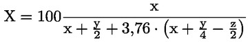

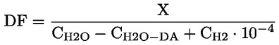
|
3.9. |
An addition to the requirements of Paragraph 1.3. of Appendix 8 to Annex 4, the following requirements shall apply: Non-methane hydrocarbon concentration is calculated as follows: CNMHC = CTHC — (Rf CH4 × CCH4) where:
|
|
3.10. |
Paragraph 1.5.2.3 of Appendix 8 to Annex 4 shall be understood as including the following:
|
|
3.11. |
References to HC should be understood as references to THC in the following paragraphs: (a) Paragraph 4.3.1.1; (b) Paragraph 4.3.2; (c) Appendix 6 — Paragraph 2.2; (d) Appendix 8 — Paragraph 1.3; (e) Appendix 8 — Paragraph 1.5.1.3; (f) Appendix 8 — Paragraph 1.5.2.3; (g) Appendix 8 — Paragraph 2.1. |
|
3.12. |
References to hydrocarbons should be understood as references to total hydrocarbons in the following paragraphs: (a) Paragraph 4.3.1.1; (b) Paragraph 4.3.2; (c) Paragraph 7.2.8. |
|
3.13. |
Technical requirements for a vehicle equipped with a periodically regenerating system
|
|
3.14. |
As from the dates laid down in Article 2 of Commission Directive 2008/89/EC ( 51 ) the daytime running lamps of the vehicle as defined in Section 2 of UN/ECE Regulation No 48 ( 52 ) shall be switched on during the test cycle. The vehicle tested shall be equipped with the daytime running lamp system that has the highest electrical energy consumption among the daytime running lamp systems, which are fitted by the manufacturer to vehicles in the group represented by the type-approved vehicle. The manufacturer shall supply appropriate technical documentation to the type-approval authorities in this respect. |
ANNEX IIIA
VERIFYING REAL DRIVING EMISSIONS
1. INTRODUCTION, DEFINITIONS AND ABBREVIATIONS
1.1. Introduction
This Annex describes the procedure to verify the Real Driving Emissions (RDE) performance of light passenger and commercial vehicles.
1.2. Definitions
|
1.2.1. |
‘Accuracy’ means the deviation between a measured or calculated value and a traceable reference value. |
|
1.2.2. |
‘Analyser’ means any measurement device that is not part of the vehicle but installed to determine the concentration or the amount of gaseous or particle pollutants. |
|
1.2.3. |
‘Axis intercept’ of a linear regression (a 0) means:
where:
|
|
1.2.4. |
‘Calibration’ means the process of setting the response of an analyser, flow-measuring instrument, sensor, or signal so that its output agrees with one or multiple reference signals. |
|
1.2.5. |
‘Coefficient of determination’ (r 2) means:
where:
|

|
1.2.6. |
‘Cross-correlation coefficient’ (r) means:
where:
|
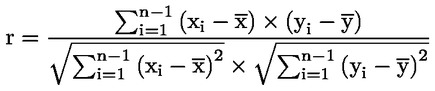
|
1.2.7. |
‘Delay time’ means the time from the gas flow switching (t0) until the response reaches 10 per cent (t10) of the final reading. |
|
1.2.8. |
‘Engine control unit (ECU) signals or data’ means any vehicle information and signal recorded from the vehicle network using the protocols specified in point 3.4.5.of Appendix 1. |
|
1.2.9. |
‘Engine control unit’ means the electronic unit that controls various actuators to ensure the optimal performance of the powertrain. |
|
1.2.10. |
‘Emissions’ also referred to as ‘components’, ‘pollutant components’ or ‘pollutant emissions’ means the regulated gaseous or particle constituents of the exhaust. |
|
1.2.11. |
‘Exhaust’, also referred to as exhaust gas, means the total of all gaseous and particulate components emitted at the exhaust outlet or tailpipe as the result of fuel combustion within the vehicle's internal combustion engine. |
|
1.2.12. |
‘Exhaust emissions’ means the emissions of particles, characterised as particulate matter and particle number, and of gaseous components at the tailpipe of a vehicle. |
|
1.2.13. |
‘Full scale’ means the full range of an analyser, flow-measuring instrument or sensor as specified by the equipment manufacturer. If a sub-range of the analyser, flow-measuring instrument or sensor is used for measurements, full scale shall be understood as the maximum reading. |
|
1.2.14. |
‘Hydrocarbon response factor’ of a particular hydrocarbon species means the ratio between the reading of a FID and the concentration of the hydrocarbon species under consideration in the reference gas cylinder, expressed as ppmC1. |
|
1.2.15. |
‘Major maintenance’ means the adjustment, repair or replacement of an analyser, flow-measuring instrument or sensor that could affect the accuracy of measurements. |
|
1.2.16. |
‘Noise’ means two times the root mean square of ten standard deviations, each calculated from the zero responses measured at a constant recording frequency of at least 1,0 Hz during a period of 30 seconds. |
|
1.2.17. |
‘Non-methane hydrocarbons’ (NMHC) means the total hydrocarbons (THC) excluding methane (CH4). |
|
1.2.18. |
‘Particle number’ (PN) means as the total number of solid particles emitted from the vehicle exhaust as defined by the measurement procedure provided for by this Regulation for assessing the respective Euro 6 emission limit defined in Table 2 of Annex I to Regulation (EC) No 715/2007. |
|
1.2.19. |
‘Precision’ means 2,5 times the standard deviation of 10 repetitive responses to a given traceable standard value. |
|
1.2.20. |
‘Reading’ means the numerical value displayed by an analyser, flow-measuring instrument, sensor or any other measurement devise applied in the context of vehicle emission measurements. |
|
1.2.21. |
‘Response time’ (t 90) means the sum of the delay time and the rise time. |
|
1.2.22. |
‘Rise time’ means the time between the 10 per cent and 90 per cent response (t90 – t10) of the final reading. |
|
1.2.23. |
‘Root mean square’ (x rms) means the square root of the arithmetic mean of the squares of values and defined as:
where:
|

|
1.2.24. |
‘Sensor’ means any measurement device that is not part of the vehicle itself but installed to determine parameters other than the concentration of gaseous and particle pollutants and the exhaust mass flow. |
|
1.2.25. |
‘Span’ means the calibration of an analyser, flow-measuring instrument, or sensor so that it gives an accurate response to a standard that matches as closely as possible the maximum value expected to occur during the actual emissions test. |
|
1.2.26. |
‘Span response’ means the mean response to a span signal over a time interval of at least 30 seconds. |
|
1.2.27. |
‘Span response drift’ means the difference between the mean response to a span signal and the actual span signal that is measured at a defined time period after an analyser, flow-measuring instrument or sensor was accurately spanned. |
|
1.2.28. |
‘Slope’ of a linear regression (a 1) means:
where:
|

|
1.2.29. |
‘Standard error of estimate’ (SEE) means:
where:
|

|
1.2.30. |
‘Total hydrocarbons’ (THC) means the sum of all volatile compounds measurable by a flame ionisation detector (FID). |
|
1.2.31. |
‘Traceable’ means the ability to relate a measurement or reading through an unbroken chain of comparisons to a known and commonly agreed standard. |
|
1.2.32. |
‘Transformation time’ means the time difference between a change of concentration or flow (t 0) at the reference point and a system response of 50 per cent of the final reading (t 50). |
|
1.2.33. |
‘Type of analyser’, also referred to as ‘analyser type’ means a group of analysers produced by the same manufacturer that apply an identical principle to determine the concentration of one specific gaseous component or the number of particles. |
|
1.2.34. |
‘Type of exhaust mass flow meter’ means a group of exhaust mass flow meters produced by the same manufacturer that share a similar tube inner diameter and function on an identical principle to determine the mass flow rate of the exhaust gas. |
|
1.2.35. |
‘Validation’ means the process of evaluating the correct installation and functionality of a Portable Emissions Measurement System and the correctness of exhaust mass flow rate measurements as obtained from one or multiple non-traceable exhaust mass flow meters or as calculated from sensors or ECU signals. |
|
1.2.36. |
‘Verification’ means the process of evaluating whether the measured or calculated output of an analyser, flow-measuring instrument, sensor or signal agrees with a reference signal within one or more predetermined thresholds for acceptance. |
|
1.2.37. |
‘Zero’ means the calibration of an analyser, flow-measuring instrument or sensor so that it gives an accurate response to a zero signal. |
|
1.2.38. |
‘Zero response’ means the mean response to a zero signal over a time interval of at least 30 seconds. |
|
1.2.39. |
‘Zero response drift’ means the difference between the mean response to a zero signal and the actual zero signal that is measured over a defined time period after an analyser, flow-measuring instrument or sensor has been accurately zero calibrated. |
1.3. Abbreviations
Abbreviations refer generically to both the singular and the plural forms of abbreviated terms.
|
CH4 |
— |
Methane |
|
CLD |
— |
Chemiluminescence Detector |
|
CO |
— |
Carbon Monoxide |
|
CO2 |
— |
Carbon Dioxide |
|
CVS |
— |
Constant Volume Sampler |
|
DCT |
— |
Dual Clutch Transmission |
|
ECU |
— |
Engine Control Unit |
|
EFM |
— |
Exhaust mass Flow Meter |
|
FID |
— |
Flame Ionisation Detector |
|
FS |
— |
full scale |
|
GPS |
— |
Global Positioning System |
|
H2O |
— |
Water |
|
HC |
— |
Hydrocarbons |
|
HCLD |
— |
Heated Chemiluminescence Detector |
|
HEV |
— |
Hybrid Electric Vehicle |
|
ICE |
— |
Internal Combustion Engine |
|
ID |
— |
identification number or code |
|
LPG |
— |
Liquid Petroleum Gas |
|
MAW |
— |
Moving Average Window |
|
max |
— |
maximum value |
|
N2 |
— |
Nitrogen |
|
NDIR |
— |
Non-Dispersive Infrared |
|
NDUV |
— |
Non-Dispersive Ultraviolet |
|
NEDC |
— |
New European Driving Cycle |
|
NG |
— |
Natural Gas |
|
NMC |
— |
Non-Methane Cutter |
|
NMC-FID |
— |
Non-Methane Cutter in combination with a Flame-Ionisation Detector |
|
NMHC |
— |
Non-Methane Hydrocarbons |
|
NO |
— |
Nitrogen Monoxide |
|
No |
— |
number |
|
NO2 |
— |
Nitrogen Dioxide |
|
NOX |
— |
Nitrogen Oxides |
|
NTE |
— |
Not-to-exceed |
|
O2 |
— |
Oxygen |
|
OBD |
— |
On-Board Diagnostics |
|
PEMS |
— |
Portable Emissions Measurement System |
|
PHEV |
— |
Plug-in Hybrid Electric Vehicle |
|
PN |
— |
particle number |
|
RDE |
— |
Real Driving Emissions |
|
SCR |
— |
Selective Catalytic Reduction |
|
SEE |
— |
Standard Error of Estimate |
|
THC |
— |
Total Hydrocarbons |
|
UN/ECE |
— |
United Nations Economic Commission for Europe |
|
VIN |
— |
Vehicle Identification Number |
|
WLTC |
— |
Worldwide harmonised light vehicles test cycle |
|
WWH-OBD |
— |
Worldwide Harmonised On-Board Diagnostics |
2. GENERAL REQUIREMENTS
|
2.1. |
Throughout its normal life, the emissions of a vehicle type-approved according to Regulation (EC) No 715/2007 as determined according to the requirements of this Annex and emitted at a RDE test performed in accordance to the requirements of this Annex, shall not be higher than the following not-to-exceed (NTE) values: NTEpollutant = CFpollutant × EURO-6 where EURO-6 is the applicable Euro 6 emission limit in Table 2 of Annex I to Regulation (EC) No 715/2007 and CFpollutant the conformity factor for the respective pollutant specified as follows:
|
|
2.2. |
The manufacturer shall confirm compliance with point 2.1 by completing the certificate set out in Appendix 9. |
|
2.3. |
The RDE tests required by this Annex at type-approval and during the lifetime of a vehicle provide a presumption of conformity with the requirement set out in point 2.1. The presumed conformity may be reassessed by additional RDE tests. |
|
2.4. |
Member States shall ensure that vehicles can be tested with PEMS on public roads in accordance with the procedures under their own national law, while respecting local road traffic legislation and safety requirements. |
|
2.5. |
Manufacturers shall ensure that vehicles can be tested with PEMS by an independent party on public roads fulfilling the requirements of point 2.4, e.g. by making available suitable adapters for exhaust pipes, granting access to ECU signals and making the necessary administrative arrangements. If the respective PEMS test is not required by this Regulation the manufacturer may charge a reasonable fee as set out in Article 7(1) of Regulation (EC) No 715/2007. |
3. RDE TEST TO BE PERFORMED
|
3.1. |
The following requirements apply to PEMS tests referred to in Article 3(10), second sub-paragraph.
|
4. GENERAL REQUIREMENTS
|
4.1. |
The RDE performance shall be demonstrated by testing vehicles on the road operated over their normal driving patterns, conditions and payloads. The RDE test shall be representative for vehicles operated on their real driving routes, with their normal load. |
|
4.2. |
The manufacturer shall demonstrate to the approval authority that the chosen vehicle, driving patterns, conditions and payloads are representative for the vehicle family. The payload and altitude requirements, as specified in points 5.1 and 5.2, shall be used ex-ante to determine whether the conditions are acceptable for RDE testing. |
|
4.3. |
The approval authority shall propose a test trip in urban, rural and motorway environments meeting the requirements of point 6. For the purpose of trip selection, the definition of urban, rural and motorway operation shall be based on a topographic map. |
|
4.4. |
If for a vehicle the collection of ECU data influences the vehicle's emissions or performance the entire PEMS test family to which the vehicle belongs as defined in Appendix 7 shall be considered as non-compliant. Such functionality shall be considered as a ‘defeat device’ as defined in Article 3(10) of Regulation (EC) No 715/2007. |
5. BOUNDARY CONDITIONS
5.1. Vehicle payload and test mass
|
5.1.1. |
The vehicle's basic payload shall comprise the driver, a witness of the test (if applicable) and the test equipment, including the mounting and the power supply devices. |
|
5.1.2. |
For the purpose of testing some artificial payload may be added as long as the total mass of the basic and artificial payload does not exceed 90 % of the sum of the ‘mass of the passengers’ and the ‘pay-mass’ defined in points 19 and 21 of Article 2 of Commission Regulation (EU) No 1230/2012 ( 53 ). |
5.2. Ambient conditions
|
5.2.1. |
The test shall be conducted under ambient conditions laid down in this section. The ambient conditions become ‘extended’ when at least one of the temperature and altitude conditions is extended. |
|
5.2.2. |
Moderate altitude conditions: Altitude lower or equal to 700 metres above sea level. |
|
5.2.3. |
Extended altitude conditions: Altitude higher than 700 metres above sea level and lower or equal to 1 300 metres above sea level. |
|
5.2.4. |
Moderate temperature conditions: Greater than or equal to 273 K (0 °C) and lower than or equal to 303 K (30 °C) |
|
5.2.5. |
Extended temperature conditions: Greater than or equal to 266 K (– 7 °C) and lower than 273 K (0 °C) or greater than 303 K (30 °C) and lower than or equal to 308 K (35 °C) |
|
5.2.6. |
By way of derogation from the provisions of points 5.2.4 and 5.2.5 the lower temperature for moderate conditions shall be greater or equal to 276K (3 °C) and the lower temperature for extended conditions shall be greater or equal to 271 K (– 2 °C) between the start of the application of binding NTE emission limits as defined in Section 2.1 and until five years after the dates given in paragraphs 4 and 5 of Article 10 of Regulation (EC) No 715/2007. |
|
5.3. |
Dynamic conditions |
|
5.4. |
The dynamic conditions encompass the effect of road grade, head wind and driving dynamics (accelerations, decelerations) and auxiliary systems upon energy consumption and emissions of the test vehicle. The verification of the normality of dynamic conditions shall be done after the test is completed, using the recorded PEMS data. The methods for verifying the normality of the dynamic conditions, are laid down in Appendices 5 and 6 of this Annex. Each method includes a reference for dynamic conditions, ranges around the reference and the minimum coverage requirements to achieve a valid test. |
|
5.5. |
Vehicle condition and operation
|
6. TRIP REQUIREMENTS
|
6.1. |
The shares of urban, rural and motorway driving, classified by instantaneous speed as described in points 6.3 to 6.5, shall be expressed as a percentage of the total trip distance. |
|
6.2. |
The trip sequence shall consist of urban driving followed by rural and motorway driving according to the shares specified in point 6.6. The urban, rural and motorway operation shall be run continuously. Rural operation may be interrupted by short periods of urban operation when driving through urban areas. Motorway operation may be interrupted by short periods of urban or rural operation, e.g. when passing toll stations or sections of road work. If another testing order is justified for practical reasons, the order of urban, rural and motorway operation may be altered, after obtaining approval from the approval authority. |
|
6.3. |
Urban operation is characterised by vehicle speeds up to 60 km/h. |
|
6.4. |
Rural operation is characterised by vehicle speeds between 60 and 90 km/h. |
|
6.5. |
Motorway operation is characterised by speeds above 90 km/h. |
|
6.6. |
The trip shall consist of approximately 34 % per cent urban, 33 % per cent rural and 33 % per cent motorway operation classified by speed as described in points 6.3 to 6.5 above. ‘Approximately’ shall mean the interval of ± 10 per cent points around the stated percentages. The urban operation shall however never be less than 29 % of the total trip distance. |
|
6.7. |
The vehicle velocity shall normally not exceed 145 km/h. This maximum speed may be exceeded by a tolerance of 15 km/h for not more than 3 % of the time duration of the motorway driving. Local speed limits remain in force at a PEMS test, notwithstanding other legal consequences. Violations of local speed limits per se do not invalidate the results of a PEMS test. |
|
6.8. |
The average speed (including stops) of the urban driving part of the trip should be between 15 and 30 km/h. Stop periods, defined as vehicle speed of less than 1 km/h, shall account for at least 10 % of the time duration of urban operation. Urban operation shall contain several stop periods of 10 s or longer. The inclusion of one excessively long stop period that individually comprises >80 % of the total stop time of urban operation shall be avoided. |
|
6.9. |
The speed range of the motorway driving shall properly cover a range between 90 and at least 110 km/h. The vehicle's velocity shall be above 100 km/h for at least 5 minutes. |
|
6.10. |
The trip duration shall be between 90 and 120 minutes. |
|
6.11. |
The start and the end point shall not differ in their elevation above sea level by more than 100 m. |
|
6.12. |
The minimum distance of each operation: urban, rural and motorway, shall be 16 km. |
7. OPERATIONAL REQUIREMENTS
|
7.1. |
The trip shall be selected in such a way that the testing is uninterrupted and the data continuously recorded to reach the minimum test duration defined in point 6.10. |
|
7.2. |
Electrical power shall be supplied to the PEMS by an external power supply unit and not from a source that draws its energy either directly or indirectly from the engine of the test vehicle. |
|
7.3. |
The installation of the PEMS equipment shall be done in a way to influence the vehicle emissions or performance or both to the minimum extent possible. Care should be exercised to minimise the mass of the installed equipment and potential aerodynamic modifications of the test vehicle. The vehicle payload shall be in accordance with point 5.1. |
|
7.4. |
RDE tests shall be conducted on working days as defined for the Union in Council Regulation (EEC, Euratom) No 1182/71 ( 54 ). |
|
7.5. |
RDE tests shall be conducted on paved roads and streets (e.g. off-road operation is not permitted). |
|
7.6 |
Prolonged idling shall be avoided after the first ignition of the combustion engine at the beginning of the emissions test. If the engine stalls during the test, it may be restarted, but the sampling shall not be interrupted. |
8. LUBRICATING OIL, FUEL AND REAGENT
|
8.1. |
The fuel, lubricant and reagent (if applicable) used for RDE testing shall be within the specifications issued by the manufacturer for vehicle operation by the customer. |
|
8.2. |
Samples of fuel, lubricant and reagent (if applicable) shall be taken and kept for at least 1 year. |
9. EMISSIONS AND TRIP EVALUATION
|
9.1. |
The test shall be conducted in accordance with Appendix 1 of this Annex. |
|
9.2. |
The trip shall fulfil the requirements set out in points 4 to 8. |
|
9.3. |
It shall not be permitted to combine data of different trips or to modify or remove data from a trip. |
|
9.4. |
After establishing the validity of a trip according to Point 9.2 emission results shall be calculated using the methods laid down in Appendix 5 and Appendix 6 of this Annex. |
|
9.5. |
If during a particular time interval the ambient conditions are extended according to point 5.2, the emissions during this particular time interval calculated according to Appendix 4 of this Annex shall be divided by a value ext before being evaluated for compliance with the requirements of this Annex. |
|
9.6. |
The cold start is defined in accordance with point 4 of Appendix 4 of this Annex. Until specific requirements for emissions at cold start are applied, the latter shall be recorded but excluded from the emissions evaluation. |
Appendix 1
Test procedure for vehicle emissions testing with a Portable Emissions Measurement System (PEMS)
1. INTRODUCTION
This Appendix describes the test procedure to determine exhaust emissions from light passenger and commercial vehicles using a Portable Emissions Measurement System.
2. SYMBOLS
|
≤ |
— |
smaller or equal |
|
# |
— |
number |
|
#/m3 |
— |
number per cubic metre |
|
% |
— |
per cent |
|
°C |
— |
degree centigrade |
|
g |
— |
gramme |
|
g/s |
— |
gramme per second |
|
h |
— |
hour |
|
Hz |
— |
hertz |
|
K |
— |
kelvin |
|
kg |
— |
kilogramme |
|
kg/s |
— |
kilogramme per second |
|
km |
— |
kilometre |
|
km/h |
— |
kilometre per hour |
|
kPa |
— |
kilopascal |
|
kPa/min |
— |
kilopascal per minute |
|
l |
— |
litre |
|
l/min |
— |
litre per minute |
|
m |
— |
metre |
|
m3 |
— |
cubic-metre |
|
mg |
— |
milligram |
|
min |
— |
minute |
|
p e |
— |
evacuated pressure [kPa] |
|
qvs |
— |
volume flow rate of the system [l/min] |
|
ppm |
— |
parts per million |
|
ppmC1 |
— |
parts per million carbon equivalent |
|
rpm |
— |
revolutions per minute |
|
s |
— |
second |
|
V s |
— |
system volume [l] |
3. GENERAL REQUIREMENTS
3.1. PEMS
The test shall be carried out with a PEMS, composed of components specified in points 3.1.1 to 3.1.5. If applicable, a connection with the vehicle ECU may be established to determine relevant engine and vehicle parameters as specified in point 3.2.
|
3.1.1. |
Analysers to determine the concentration of pollutants in the exhaust gas. |
|
3.1.2. |
One or multiple instruments or sensors to measure or determine the exhaust mass flow. |
|
3.1.3. |
A Global Positioning System to determine the position, altitude and, speed of the vehicle. |
|
3.1.4. |
If applicable, sensors and other appliances being not part of the vehicle, e.g. to measure ambient temperature, relative humidity, air pressure, and vehicle speed. |
|
3.1.5. |
An energy source independent of the vehicle to power the PEMS. |
3.2. Test parameters
Test parameters as specified in Table 1 of this Annex shall be measured, recorded at a constant frequency of 1,0 Hz or higher and reported according to the requirements of Appendix 8. If ECU parameters are obtained, these should be made available at a substantially higher frequency than the parameters recorded by PEMS to ensure correct sampling. The PEMS analysers, flow-measuring instruments and sensors shall comply with the requirements laid down in Appendices 2 and 3 of this Annex.
Table 1
Test parameters
|
Parameter |
Recommended unit |
Source (8) |
|
ppm |
Analyser |
|
|
ppm |
Analyser |
|
|
ppm |
Analyser (6) |
|
|
ppm |
Analyser |
|
|
CO2 concentration (1) |
ppm |
Analyser |
|
ppm |
Analyser (7) |
|
|
PN concentration (4) |
#/m3 |
Analyser |
|
Exhaust mass flow rate |
kg/s |
EFM, any methods described in point 7 of Appendix 2 |
|
Ambient humidity |
% |
Sensor |
|
Ambient temperature |
K |
Sensor |
|
Ambient pressure |
kPa |
Sensor |
|
Vehicle speed |
km/h |
Sensor, GPS, or ECU (3) |
|
Vehicle latitude |
Degree |
GPS |
|
Vehicle longitude |
Degree |
GPS |
|
M |
GPS or Sensor |
|
|
Exhaust gas temperature (5) |
K |
Sensor |
|
Engine coolant temperature (5) |
K |
Sensor or ECU |
|
Engine speed (5) |
rpm |
Sensor or ECU |
|
Engine torque (5) |
Nm |
Sensor or ECU |
|
Torque at driven axle (5) |
Nm |
Rim torque meter |
|
Pedal position (5) |
% |
Sensor or ECU |
|
Engine fuel flow (2) |
g/s |
Sensor or ECU |
|
Engine intake air flow (2) |
g/s |
Sensor or ECU |
|
Fault status (5) |
— |
ECU |
|
Intake air flow temperature |
K |
Sensor or ECU |
|
Regeneration status (5) |
— |
ECU |
|
Engine oil temperature (5) |
K |
Sensor or ECU |
|
Actual gear (5) |
# |
ECU |
|
Desired gear (e.g. gear shift indicator) (5) |
# |
ECU |
|
Other vehicle data (5) |
unspecified |
ECU |
|
(1) To be measured on a wet basis or to be corrected as described in point 8.1 of Appendix 4. (2) To be determined only if indirect methods are used to calculate exhaust mass flow rate as described in paragraphs 10.2 and 10.3 of Appendix 4. (3) The method to determine vehicle speed shall be chosen according to point 4.7. (4) Parameter only mandatory if measurement required by Annex IIIA, Section 2.1. (5) To be determined only if necessary to verify the vehicle status and operating conditions. (6) May be calculated from THC and CH4 concentrations according to point 9.2 of Appendix 4. (7) May be calculated from measured NO and NO2 concentrations. (8) Multiple parameter sources may be used. (9) The preferable source is the ambient pressure sensor. |
||
3.3. Preparation of the vehicle
The preparation of the vehicle shall include a general technical and operational check.
3.4. Installation of PEMS
3.4.1. General
The installation of the PEMS shall follow the instructions of the PEMS manufacturer and the local health and safety regulations. The PEMS should be installed as to minimise during the test electromagnetic interferences as well as exposure to shocks, vibration, dust and variability in temperature. The installation and operation of the PEMS shall be leak-tight and minimise heat loss. The installation and operation of PEMS shall not change the nature of the exhaust gas nor unduly increase the length of the tailpipe. To avoid the generation of particles, connectors shall be thermally stable at the exhaust gas temperatures expected during the test. It is recommended not to use elastomer connectors to connect the vehicle exhaust outlet and the connecting tube. Elastomer connectors, if used, shall have a minimum exposure to the exhaust gas to avoid artefacts at high engine load.
3.4.2. Permissible backpressure
The installation and operation of the PEMS shall not unduly increase the static pressure at the exhaust outlet. If technically feasible, any extension to facilitate the sampling or connection with the exhaust mass flow meter shall have an equivalent, or larger, cross-sectional area as the exhaust pipe.
3.4.3. Exhaust mass flow meter
Whenever used, the exhaust mass flow meter shall be attached to the vehicle's tailpipe(s) according to the recommendations of the EFM manufacturer. The measurement range of the EFM shall match the range of the exhaust mass flow rate expected during the test. The installation of the EFM and any exhaust pipe adaptors or junctions shall not adversely affect the operation of the engine or exhaust after-treatment system. A minimum of four pipe diameters or 150 mm of straight tubing, whichever is larger, shall be placed either side of the flow-sensing element. When testing a multi-cylinder engine with a branched exhaust manifold, it is recommended to combine the manifolds upstream of the exhaust mass flow meter and to increase the cross section of the piping appropriately as to minimise backpressure in the exhaust. If this is not feasible, exhaust flow measurements with several exhaust mass flow meters shall be considered. The wide variety of exhaust pipe configurations, dimensions and expected exhaust mass flow rates may require compromises, guided by good engineering judgement, when selecting and installing the EFM(s). If measurement accuracy requires, it is permissible to install an EFM with a diameter smaller than that of the exhaust outlet or the total cross-sectional area of multiple outlets, providing it does not adversely affect the operation or the exhaust after-treatment as specified in point 3.4.2.
3.4.4. Global Positioning System
The GPS antenna should be mounted, e.g. at the highest possible location, as to ensure good reception of the satellite signal. The mounted GPS antenna shall interfere as little as possible with the vehicle operation.
3.4.5. Connection with the Engine Control Unit
If desired, relevant vehicle and engine parameters listed in Table 1 can be recorded by using a data logger connected with the ECU or the vehicle network following standards, e.g. ISO 15031-5 or SAE J1979, OBD-II, EOBD or WWH-OBD. If applicable, manufacturers shall disclose parameter labels to allow the identification of required parameters.
3.4.6. Sensors and auxiliary equipment
Vehicle speed sensors, temperature sensors, coolant thermocouples or any other measurement device not part of the vehicle shall be installed to measure the parameter under consideration in a representative, reliable and accurate manner without unduly interfering with the vehicle operation and the functioning of other analysers, flow-measuring instruments, sensors and signals. Sensors and auxiliary equipment shall be powered independently of the vehicle.
3.5. Emissions sampling
Emissions sampling shall be representative and conducted at locations of well-mixed exhaust where the influence of ambient air downstream of the sampling point is minimal. If applicable, emissions shall be sampled downstream of the exhaust mass flow meter, respecting a distance of at least 150 mm to the flow sensing element. The sampling probes shall be fitted at least 200 mm or three times the diameter of the exhaust pipe, whichever is larger, upstream of the vehicle's exit of the exhaust outlet, which is the point at which the exhaust exits the PEMS sampling installation into the environment. If the PEMS feeds back a flow to the tail pipe, this shall occur downstream of the sampling probe in a manner that does not affect during engine operation the nature of the exhaust gas at the sampling point(s). If the length of the sample line is changed, the system transport times shall be verified and if necessary corrected.
If the engine is equipped with an exhaust after-treatment system, the exhaust sample shall be taken downstream of the exhaust after-treatment system. When testing a vehicle with a multi-cylinder engine and branched exhaust manifold, the inlet of the sampling probe shall be located sufficiently far downstream so as to ensure that the sample is representative of the average exhaust emissions of all cylinders. In multi-cylinder engines, having distinct groups of manifolds, such as in a ‘V’ engine configuration, the manifolds shall be combined upstream of the sampling probe. If this is technically not feasible, multi-point sampling at locations of well-mixed exhaust free of ambient air shall be considered. In this case, the number and location of sampling probes shall match as far as possible that of the exhaust mass flow meters. In case of unequal exhaust flows, proportional sampling or sampling with multiple analysers shall be considered.
If particles are measured, the exhaust shall be sampled from the centre of the exhaust stream. If several probes are used for emissions sampling, the particle sampling probe shall be placed upstream of the other sampling probes.
If hydrocarbons are measured, the sampling line shall be heated to 463 ± 10 K (190 ± 10 °C). For the measurement of other gaseous components with or without cooler, the sampling line shall be kept at a minimum of 333 K (60 °C) as to avoid condensation and to ensure appropriate penetration efficiencies of the various gases. For low pressure sampling systems, the temperature can be lowered corresponding to the pressure decrease provided that the sampling system ensures a penetration efficiency of 95 % for all regulated gaseous pollutants. If particles are sampled, the sampling line from the raw exhaust sample point shall be heated to a minimum of 373 K (100 °C). The residence time of the sample in the particle sampling line shall be less than 3 s until reaching first dilution or the particle counter.
4. PRE-TEST PROCEDURES
4.1. PEMS leak check
After the installation of PEMS is completed, a leak check shall be performed at least once for each PEMS-vehicle installation as prescribed by the PEMS manufacturer or as follows. The probe shall be disconnected from the exhaust system and the end plugged. The analyser pump shall be switched on. After an initial stabilisation period all flow meters shall read approximately zero in the absence of a leak. Else, the sampling lines shall be checked and the fault corrected.
The leakage rate on the vacuum side shall not exceed 0,5 per cent of the in-use flow rate for the portion of the system being checked. The analyser flows and bypass flows may be used to estimate the in-use flow rates.
Alternatively, the system may be evacuated to a pressure of at least 20 kPa vacuum (80 kPa absolute). After an initial stabilisation period the pressure increase Dp (kPa/min) in the system shall not exceed:
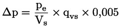
Alternatively, a concentration step change at the beginning of the sampling line shall be introduced by switching from zero to span gas while maintaining the same pressure conditions as under normal system operation. If for a correctly calibrated analyser after an adequate period of time the reading is ≤ 99 per cent compared to the introduced concentration, the leakage problem shall be corrected.
4.2. Starting and stabilising the PEMS
The PEMS shall be switched on, warmed up and stabilised according to the specifications of the PEMS manufacturer until, e.g. pressures, temperatures and flows have reached their operating set points.
4.3. Preparing the sampling system
The sampling system, consisting of the sampling probe, sampling lines and the analysers, shall be prepared for testing by following the instruction of the PEMS manufacturer. It shall be ensured that the sampling system is clean and free of moisture condensation.
4.4. Preparing the EFM
If used for measuring the exhaust mass flow, the EFM shall be purged and prepared for operation in accordance with the specifications of the EFM manufacturer. This procedure shall, if applicable, remove condensation and deposits from the lines and the associated measurement ports.
4.5. Checking and calibrating the analysers for measuring gaseous emissions
Zero and span calibration adjustments of the analysers shall be performed using calibration gases that meet the requirements of point 5 of Appendix 2. The calibration gases shall be chosen to match the range of pollutant concentrations expected during the emissions test.
4.6. Checking the analyser for measuring particle emissions
The zero level of the analyser shall be recorded by sampling HEPA filtered ambient air. The signal shall be recorded at a constant frequency of at least 1,0 Hz over a period of 2 min and averaged; the permissible concentration value shall be determined once suitable measurement equipment becomes available.
4.7. Measuring vehicle speed
Vehicle speed shall be determined by at least one of the following methods:
(a) a GPS; if vehicle speed is determined by a GPS, the total trip distance shall be checked against the measurements of another method according to point 7 of Appendix 4,
(b) a sensor (e.g. optical or micro-wave sensor); if vehicle speed is determined by a sensor, the speed measurements shall comply with the requirements of point 8 of Appendix 2, or alternatively, the total trip distance determined by the sensor shall be compared with a reference distance obtained from a digital road network or topographic map. The total trip distance determined by the sensor shall deviate by no more than 4 % from the reference distance,
(c) the ECU; if vehicle speed is determined by the ECU, the total trip distance shall be validated according to point 3 of Appendix 3 and the ECU speed signal adjusted, if necessary to fulfil the requirements of point 3.3 of Appendix 3. Alternatively, the total trip distance as determined by the ECU shall be compared with a reference distance obtained from a digital road network or topographic map. The total trip distance determined by the ECU shall deviate by no more than 4 % from the reference.
4.8. Check of PEMS set-up
The correctness of connections with all sensors and, if applicable, the ECU shall be verified. If engine parameters are retrieved, it shall be ensured that the ECU reports values correctly (e.g. zero engine speed (rpm) while the combustion engine is in key-on-engine-off status). The PEMS shall function free of warning signals and error indication.
5. EMISSIONS TEST
5.1. Test start
Sampling, measurement and recording of parameters shall begin prior to the start of the engine. To facilitate time alignment, it is recommended to record the parameters that are subject to time alignment either by a single data recording device or with a synchronised time stamp. Before as well as directly after engine start, it shall be confirmed that all necessary parameters are recorded by the data logger.
5.2. Test
Sampling, measurement and recording of parameters shall continue throughout the on-road test of the vehicle. The engine may be stopped and started, but emissions sampling and parameter recording shall continue. Any warning signals, suggesting malfunctioning of the PEMS, shall be documented and verified. Parameter recording shall reach a data completeness of higher than 99 %. Measurement and data recording may be interrupted for less than 1 % of the total trip duration but for no more than a consecutive period of 30 s solely in the case of unintended signal loss or for the purpose of PEMS system maintenance. Interruptions may be recorded directly by the PEMS but it is not permissible to introduce interruptions in the recorded parameter via the pre-processing, exchange or post-processing of data. If conducted, auto zeroing shall be performed against a traceable zero standard similar to the one used to zero the analyser. It is strongly recommended to initiate PEMS system maintenance during periods of zero vehicle speed.
5.3. Test end
The end of the test is reached when the vehicle has completed the trip and the combustion engine is switched off. The data recording shall continue until the response time of the sampling systems has elapsed.
6. POST-TEST PROCEDURE
6.1. Checking the analysers for measuring gaseous emissions
The zero and span of the analysers of gaseous components shall be checked by using calibration gases identical to the ones applied under point 4.5 to evaluate the analyser response drift compared to the pre-test calibration. It is permissible to zero the analyser prior to verifying the span drift, if the zero drift was determined to be within the permissible range. The post-test drift check shall be completed as soon as possible after the test and before the PEMS, or individual analysers or sensors, are turned off or have switched into a non-operating mode. The difference between the pre-test and post-test results shall comply with the requirements specified in Table 2.
Table 2
Permissible analyser drift over a PEMS test
|
Pollutant |
Zero response drift |
Span response drift (1) |
|
CO2 |
≤ 2 000 ppm per test |
≤ 2 % of reading or ≤ 2 000 ppm per test, whichever is larger |
|
CO |
≤ 75 ppm per test |
≤ 2 % of reading or ≤ 75 ppm per test, whichever is larger |
|
NO2 |
≤ 5 ppm per test |
≤ 2 % of reading or ≤ 5 ppm per test, whichever is larger |
|
NO/NOX |
≤ 5 ppm per test |
≤ 2 % of reading or ≤ 5 ppm per test, whichever is larger |
|
CH4 |
≤ 10 ppmC1 per test |
≤ 2 % of reading or ≤ 10 ppmC1 per test, whichever is larger |
|
THC |
≤ 10 ppmC1 per test |
≤ 2 % of reading or ≤ 10 ppmC1 per test, whichever is larger |
|
(1) If the zero drift is within the permissible range, it is permissible to zero the analyser prior to verifying the span drift. |
||
If the difference between the pre-test and post-test results for the zero and span drift is higher than permitted, all test results shall be voided and the test repeated.
6.2. Checking the analyser for measuring particle emissions
The zero level of the analyser shall be recorded by sampling HEPA filtered ambient air. The signal shall be recorded over a period of 2 min and averaged; the permissible final concentration shall be defined once suitable measurement equipment becomes available. If the difference between the pre-test and post-test zero and span check is higher than permitted, all test results shall be voided and the test repeated.
6.3. Checking the on-road emission measurements
The calibrated range of the analysers shall account at least for 90 % of the concentration values obtained from 99 % of the measurements of the valid parts of the emissions test. It is permissible that 1 % of the total number of measurements used for evaluation exceeds the calibrated range of the analysers by up to a factor of two. If these requirements are not met, the test shall be voided.
Appendix 2
Specifications and calibration of PEMS components and signals
1. INTRODUCTION
This appendix sets out the specifications and calibration of PEMS components and signals.
2. SYMBOLS
|
> |
— |
larger than |
|
≥ |
— |
larger than or equal to |
|
% |
— |
per cent |
|
≤ |
— |
smaller than or equal to |
|
A |
— |
undiluted CO2 concentration [%] |
|
a 0 |
— |
y-axis intercept of the linear regression line |
|
a 1 |
— |
slope of the linear regression line |
|
B |
— |
diluted CO2 concentration [%] |
|
C |
— |
diluted NO concentration [ppm] |
|
c |
— |
analyser response in the oxygen interference test |
|
c FS,b |
— |
full scale HC concentration in step (b) [ppmC1] |
|
c FS,d |
— |
full scale HC concentration in step (d) [ppmC1] |
|
c HC(w/NMC) |
— |
HC concentration with CH4 or C2H6 flowing through the NMC [ppmC1] |
|
c HC(w/o NMC) |
— |
HC concentration with CH4 or C2H6 bypassing the NMC [ppmC1] |
|
c m,b |
— |
measured HC concentration in step (b) [ppmC1] |
|
c m,d |
— |
measured HC concentration in step (d) [ppmC1] |
|
c ref,b |
— |
reference HC concentration in step (b) [ppmC1] |
|
c ref,d |
— |
reference HC concentration in step (d) [ppmC1] |
|
°C |
— |
degree centigrade |
|
D |
— |
undiluted NO concentration [ppm] |
|
D e |
— |
expected diluted NO concentration [ppm] |
|
E |
— |
absolute operating pressure [kPa] |
|
E CO2 |
— |
per cent CO2 quench |
|
E E |
— |
ethane efficiency |
|
E H2O |
— |
per cent water quench |
|
E M |
— |
methane efficiency |
|
EO2 |
— |
oxygen interference |
|
F |
— |
water temperature [K] |
|
G |
— |
saturation vapour pressure [kPa] |
|
g |
— |
gramme |
|
gH2O/kg |
— |
gramme water per kilogram |
|
h |
— |
hour |
|
H |
— |
water vapour concentration [%] |
|
H m |
— |
maximum water vapour concentration [%] |
|
Hz |
— |
hertz |
|
K |
— |
kelvin |
|
kg |
— |
kilogramme |
|
km/h |
— |
kilometre per hour |
|
kPa |
— |
kilopascal |
|
max |
— |
maximum value |
|
NOX,dry |
— |
moisture-corrected mean concentration of the stabilised NOX recordings |
|
NOX,m |
— |
mean concentration of the stabilised NOX recordings |
|
NOX,ref |
— |
reference mean concentration of the stabilised NOX recordings |
|
ppm |
— |
parts per million |
|
ppmC1 |
— |
parts per million carbon equivalents |
|
r2 |
— |
coefficient of determination |
|
s |
— |
second |
|
t0 |
— |
time point of gas flow switching [s] |
|
t10 |
— |
time point of 10 % response of the final reading |
|
t50 |
— |
time point of 50 % response of the final reading |
|
t90 |
— |
time point of 90 % response of the final reading |
|
x |
— |
independent variable or reference value |
|
χmin |
— |
minimum value |
|
y |
— |
dependent variable or measured value |
3. LINEARITY VERIFICATION
3.1. General
The linearity of analysers, flow-measuring instruments, sensors and signals, shall be traceable to international or national standards. Any sensors or signals that are not directly traceable, e.g. simplified flow-measuring instruments shall be calibrated alternatively against chassis dynamometer laboratory equipment that has been calibrated against international or national standards.
3.2. Linearity requirements
All analysers, flow-measuring instruments, sensors and signals shall comply with the linearity requirements given in Table 1. If air flow, fuel flow, the air-to-fuel ratio or the exhaust mass flow rate is obtained from the ECU, the calculated exhaust mass flow rate shall meet the linearity requirements specified in Table 1.
Table 1
Linearity requirements of measurement parameters and systems
|
Measurement parameter/instrument |
|
Slope a1 |
Standard error SEE |
Coefficient of determination r2 |
|
Fuel flow rate (1) |
≤ 1 % max |
0,98 - 1,02 |
≤ 2 % max |
≥ 0,990 |
|
Air flow rate (1) |
≤ 1 % max |
0,98 - 1,02 |
≤ 2 % max |
≥ 0,990 |
|
Exhaust mass flow rate |
≤ 2 % max |
0,97 - 1,03 |
≤ 2 % max |
≥ 0,990 |
|
Gas analysers |
≤ 0,5 % max |
0,99 - 1,01 |
≤ 1 % max |
≥ 0,998 |
|
Torque (2) |
≤ 1 % max |
0,98 - 1,02 |
≤ 2 % max |
≥ 0,990 |
|
PN analysers (3) |
tbd |
tbd |
tbd |
tbd |
|
(1) Optional to determine exhaust mass flow. (2) Optional parameter. (3) To be decided once equipment becomes available. |
||||
3.3. Frequency of linearity verification
The linearity requirements according to point 3.2 shall be verified:
(a) for each analyser at least every three months or whenever a system repair or change is made that could influence the calibration;
(b) for other relevant instruments, such as exhaust mass flow meters and traceably calibrated sensors, whenever damage is observed, as required by internal audit procedures, by the instrument manufacturer or by ISO 9000 but no longer than one year before the actual test.
The linearity requirements according to point 3.2 for sensors or ECU signals that are not directly traceable shall be performed once for each PEMS set-up with a traceably calibrated measurement device on the chassis dynamometer.
3.4. Procedure of linearity verification
3.4.1. General requirements
The relevant analysers, instruments and sensors shall be brought to their normal operating condition according to the recommendations of their manufacturer. The analysers, instruments and sensors shall be operated at their specified temperatures, pressures and flows.
3.4.2. General procedure
The linearity shall be verified for each normal operating range by executing the following steps:
(a) The analyser, flow-measuring instrument or sensor shall be set at zero by introducing a zero signal. For gas analysers, purified synthetic air or nitrogen shall be introduced to the analyser port via a gas path that is as direct and short as possible.
(b) The analyser, flow-measuring instrument or sensor shall be spanned by introducing a span signal. For gas analysers, an appropriate span gas shall be introduced to the analyser port via a gas path that is as direct and short as possible.
(c) The zero procedure of (a) shall be repeated.
(d) The verification shall be established by introducing at least 10, approximately equally spaced and valid, reference values (including zero). The reference values with respect to the concentration of components, the exhaust mass flow rate or any other relevant parameter shall be chosen to match the range of values expected during the emissions test. For measurements of exhaust mass flow, reference points below 5 % of the maximum calibration value can be excluded from the linearity verification.
(e) For gas analysers, known gas concentrations in accordance with point 5 shall be introduced to the analyser port. Sufficient time for signal stabilisation shall be given.
(f) The values under evaluation and, if needed, the reference values shall be recorded at a constant frequency of at least 1,0 Hz over a period of 30 seconds.
(g) The arithmetic mean values over the 30-second period shall be used to calculate the least squares linear regression parameters, with the best-fit equation having the form:
y = a 1 x + a 0
where:
|
y |
is the actual value of the measurement system |
|
a 1 |
is the slope of the regression line |
|
x |
is the reference value |
|
a 0 |
is the y intercept of the regression line |
The standard error of estimate (SEE) of y on x and the coefficient of determination (r2) shall be calculated for each measurement parameter and system.
(h) The linear regression parameters shall meet the requirements specified in Table 1.
3.4.3. Requirements for linearity verification on a chassis dynamometer
Non-traceable flow-measuring instruments, sensors or ECU signals that cannot directly be calibrated according to traceable standards, shall be calibrated on the chassis dynamometer. The procedure shall follow as far as applicable, the requirements of Annex 4a to UN/ECE Regulation No 83. If necessary, the instrument or sensor to be calibrated shall be installed on the test vehicle and operated according to the requirements of Appendix 1. The calibration procedure shall follow whenever possible the requirements of point 3.4.2; at least 10 appropriate reference values shall be selected as to ensure that at least 90 % of the maximum value expected to occur during the emissions test is covered.
If a not directly traceable flow-measuring instrument, sensor or ECU signal for determining exhaust flow is to be calibrated, a traceably calibrated reference exhaust mass flow meter or the CVS shall be attached to the vehicle's tailpipe. It shall be ensured that the vehicle exhaust is accurately measured by the exhaust mass flow meter according to point 3.4.3 of Appendix 1. The vehicle shall be operated by applying constant throttle at a constant gear selection and chassis dynamometer load.
4. ANALYSERS FOR MEASURING GASEOUS COMPONENTS
4.1. Permissible types of analysers
4.1.1. Standard analysers
The gaseous components shall be measured with analysers specified in points 1.3.1 to 1.3.5 of Appendix 3, Annex 4A to UN/ECE Regulation No 83, 07 series of amendments. If an NDUV analyser measures both NO and NO2, a NO2/NO converter is not required.
4.1.2. Alternative analysers
Any analyser not meeting the design specifications of point 4.1.1 is permissible provided that it fulfils the requirements of point 4.2. The manufacturer shall ensure that the alternative analyser achieves an equivalent or higher measurement performance compared to a standard analyser over the range of pollutant concentrations and co-existing gases that can be expected from vehicles operated with permissible fuels under moderate and extended conditions of valid on-road testing as specified in points 5, 6 and 7. Upon request, the manufacturer of the analyser shall submit in writing supplemental information, demonstrating that the measurement performance of the alternative analyser is consistently and reliably in line with the measurement performance of standard analysers. Supplemental information shall contain:
(a) a description of the theoretical basis and the technical components of the alternative analyser;
(b) a demonstration of equivalency with the respective standard analyser specified in point 4.1.1 over the expected range of pollutant concentrations and ambient conditions of the type-approval test defined in Annex 4a to UN/ECE Regulation No 83, 07 series of amendments as well as a validation test as described in point 3 of Appendix 3 for a vehicle equipped with a spark-ignition and compression-ignition engine; the manufacturer of the analyser shall demonstrate the significance of equivalency within the permissible tolerances given in point 3.3 of Appendix 3;
(c) a demonstration of equivalency with the respective standard analyser specified in point 4.1.1 with respect to the influence of atmospheric pressure on the measurement performance of the analyser; the demonstration test shall determine the response to span gas having a concentration within the analyser range to check the influence of atmospheric pressure under moderate and extended altitude conditions defined in point 5.2. Such a test can be performed in an altitude environmental test chamber;
(d) a demonstration of equivalency with the respective standard analyser specified in point 4.1.1 over at least three on-road tests that fulfil the requirements of this Annex;
(e) a demonstration that the influence of vibrations, accelerations and ambient temperature on the analyser reading does not exceed the noise requirements for analysers set out in point 4.2.4.
Approval authorities may request additional information to substantiate equivalency or refuse approval if measurements demonstrate that an alternative analyser is not equivalent to a standard analyser.
4.2. Analyser specifications
4.2.1. General
In addition to the linearity requirements defined for each analyser in point 3, the compliance of analyser types with the specifications laid down in points 4.2.2 to 4.2.8 shall be demonstrated by the analyser manufacturer. Analysers shall have a measuring range and response time appropriate to measure with adequate accuracy the concentrations of the exhaust gas components at the applicable emissions standard under transient and steady state conditions. The sensitivity of the analysers to shocks, vibration, aging, variability in temperature and air pressure as well as electromagnetic interferences and other impacts related to vehicle and analyser operation shall be limited as far as possible.
4.2.2. Accuracy
The accuracy, defined as the deviation of the analyser reading from the reference value, shall not exceed 2 % of reading or 0,3 % of full scale, whichever is larger.
4.2.3. Precision
The precision, defined as 2,5 times the standard deviation of 10 repetitive responses to a given calibration or span gas, shall be no greater than 1 % of the full scale concentration for a measurement range equal or above 155 ppm (or ppmC1) and 2 % of the full scale concentration for a measurement range of below 155 ppm (or ppmC1).
4.2.4. Noise
The noise, defined as two times the root mean square of ten standard deviations, each calculated from the zero responses measured at a constant recording frequency of at least 1,0 Hz during a period of 30 seconds, shall not exceed 2 % of full scale. Each of the 10 measurement periods shall be interspersed with an interval of 30 seconds in which the analyser is exposed to an appropriate span gas. Before each sampling period and before each span period, sufficient time shall be given to purge the analyser and the sampling lines.
4.2.5. Zero response drift
The drift of the zero response, defined as the mean response to a zero gas during a time interval of at least 30 seconds, shall comply with the specifications given in Table 2.
4.2.6. Span response drift
The drift of the span response, defined as the mean response to a span gas during a time interval of at least 30 seconds, shall comply with the specifications given in Table 2.
Table 2
Permissible zero and span response drift of analysers for measuring gaseous components under laboratory conditions
|
Pollutant |
Zero response drift |
Span response drift |
|
CO2 |
≤ 1 000 ppm over 4 h |
≤ 2 % of reading or ≤ 1 000 ppm over 4 h, whichever is larger |
|
CO |
≤ 50 ppm over 4 h |
≤ 2 % of reading or ≤ 50 ppm over 4 h, whichever is larger |
|
NO2 |
≤ 5 ppm over 4 h |
≤ 2 % of reading or ≤ 5 ppm over 4 h, whichever is larger |
|
NO/NOX |
≤ 5 ppm over 4 h |
≤ 2 % of reading or 5 ppm over 4h, whichever is larger |
|
CH4 |
≤ 10 ppmC1 |
≤ 2 % of reading or ≤ 10 ppmC1 over 4 h, whichever is larger |
|
THC |
≤ 10 ppmC1 |
≤ 2 % of reading or ≤ 10 ppmC1 over 4 h, whichever is larger |
4.2.7. Rise time
Rise time is defined as the time between the 10 per cent and 90 per cent response of the final reading (t 90 – t 10; see point 4.4). The rise time of PEMS analysers shall not exceed 3 seconds.
4.2.8. Gas drying
Exhaust gases may be measured wet or dry. A gas-drying device, if used, shall have a minimal effect on the composition of the measured gases. Chemical dryers are not permitted.
4.3. Additional requirements
4.3.1. General
The provisions in points 4.3.2 to 4.3.5 define additional performance requirements for specific analyser types and apply only to cases, in which the analyser under consideration is used for PEMS emission measurements.
4.3.2. Efficiency test for NOX converters
If a NOX converter is applied, for example to convert NO2 into NO for analysis with a chemiluminescence analyser, its efficiency shall be tested by following the requirements of point 2.4 of Appendix 3 of Annex 4a to UN/ECE Regulation No 83, 07 series of amendments. The efficiency of the NOX converter shall be verified no longer than one month before the emissions test.
4.3.3. Adjustment of the Flame Ionisation Detector
(a) Optimisation of the detector response
If hydrocarbons are measured, the FID shall be adjusted at intervals specified by the analyser manufacturer by following point 2.3.1 of Appendix 3 of Annex 4a to UN/ECE Regulation No 83, 07 series of amendments. A propane-in-air or propane-in-nitrogen span gas shall be used to optimise the response in the most common operating range.
(b) Hydrocarbon response factors
If hydrocarbons are measured, the hydrocarbon response factor of the FID shall be verified by following the provisions of point 2.3.3 of Appendix 3 of Annex 4a to UN/ECE Regulation No 83, 07 series of amendments, using propane-in-air or propane-in-nitrogen as span gases and purified synthetic air or nitrogen as zero gases, respectively.
(c) Oxygen interference check
The oxygen interference check shall be performed when introducing an analyser into service and after major maintenance intervals. A measuring range shall be chosen in which the oxygen interference check gases fall in the upper 50 per cent. The test shall be conducted with the oven temperature set as required. The specifications of the oxygen interference check gases are described in point 5.3.
The following procedure applies:
(i) The analyser shall be set at zero.
(ii) The analyser shall be spanned with a 0 per cent oxygen blend for positive ignition engines and a 21 per cent oxygen blend for compression ignition engines.
(iii) The zero response shall be rechecked. If it has changed by more than 0,5 per cent of full scale, steps (i) and (ii) shall be repeated.
(iv) The 5 per cent and 10 per cent oxygen interference check gases shall be introduced.
(v) The zero response shall be rechecked. If it has changed by more than ± 1 per cent of full scale, the test shall be repeated.
(vi) The oxygen interference E O2 shall be calculated for each oxygen interference check gas in step (d) as follows:

where the analyser response is:

where:
|
c ref,b |
is the reference HC concentration in step (b) [ppmC1] |
|
c ref,d |
is the reference HC concentration in step (d) [ppmC1] |
|
c FS,b |
is the full scale HC concentration in step (b) [ppmC1] |
|
c FS,d |
is the full scale HC concentration in step (d) [ppmC1] |
|
c m,b |
is the measured HC concentration in step (b) [ppmC1] |
|
c m,d |
is the measured HC concentration in step (d) [ppmC1]. |
(vii) The oxygen interference E O2 shall be less than ± 1,5 per cent for all required oxygen interference check gases.
(viii) If the oxygen interference E O2 is greater than ± 1,5 per cent, corrective action may be taken by incrementally adjusting the air flow (above and below the manufacturer's specifications), the fuel flow and the sample flow.
(ix) The oxygen interference check shall be repeated for each new setting.
4.3.4. Conversion efficiency of the non-methane cutter (NMC)
If hydrocarbons are analysed, a NMC can be used to remove non-methane hydrocarbons from the gas sample by oxidising all hydrocarbons except methane. Ideally, the conversion for methane is 0 per cent and for the other hydrocarbons represented by ethane is 100 per cent. For the accurate measurement of NMHC, the two efficiencies shall be determined and used for the calculation of the NMHC emissions (see point 9.2 of Appendix 4). It is not necessary to determine the methane conversion efficiency in case the NMC-FID is calibrated according to method (b) in point 9.2 of Appendix 4 by passing the methane/air calibration gas through the NMC.
(a) Methane conversion efficiency
Methane calibration gas shall be flown through the FID with and without bypassing the NMC; the two concentrations shall be recorded. The methane efficiency shall be determined as:

where:
|
cHC(w/NMC) |
is the HC concentration with CH4 flowing through the NMC [ppmC1] |
|
cHC(w/o NMC) |
is the HC concentration with CH4 bypassing the NMC [ppmC1] |
(b) Ethane conversion efficiency
Ethane calibration gas shall be flown through the FID with and without bypassing the NMC; the two concentrations shall be recorded. The ethane efficiency shall be determined as:
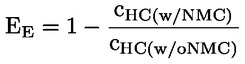
where:
|
c HC(w/NMC) |
is the HC concentration with C2H6 flowing through the NMC [ppmC1] |
|
c HC(w/o NMC) |
is the HC concentration with C2H6 bypassing the NMC [ppmC1] |
4.3.5. Interference effects
(a) General
Other gases than the ones being analysed can affect the analyser reading. A check for interference effects and the correct functionality of analysers shall be performed by the analyser manufacturer prior to market introduction at least once for each type of analyser or device addressed in points (b) to (f).
(b) CO analyser interference check
Water and CO2 can interfere with the measurements of the CO analyser. Therefore, a CO2 span gas having a concentration of 80 to 100 per cent of full scale of the maximum operating range of the CO analyser used during the test shall be bubbled through water at room temperature and the analyser response recorded. The analyser response shall not be more than 2 per cent of the mean CO concentration expected during normal on-road testing or ± 50 ppm, whichever is larger. The interference check for H2O and CO2 may be run as separate procedures. If the H2O and CO2 levels used for the interference check are higher than the maximum levels expected during the test, each observed interference value shall be scaled down by multiplying the observed interference with the ratio of the maximum expected concentration value during the test and the actual concentration value used during this check. Separate interference checks with concentrations of H2O that are lower than the maximum concentration expected during the test may be run and the observed H2O interference shall be scaled up by multiplying the observed interference with the ratio of the maximum H2O concentration value expected during the test and the actual concentration value used during this check. The sum of the two scaled interference values shall meet the tolerance specified in this point.
(c) NOX analyser quench check
The two gases of concern for CLD and HCLD analysers are CO2 and water vapour. The quench response to these gases is proportional to the gas concentrations. A test shall determine the quench at the highest concentrations expected during the test. If the CLD and HCLD analysers use quench compensation algorithms that utilise H2O or CO2 measurement analysers or both, quench shall be evaluated with these analysers active and with the compensation algorithms applied.
(i) CO2 quench check
A CO2 span gas having a concentration of 80 to 100 per cent of the maximum operating range shall be passed through the NDIR analyser; the CO2 value shall be recorded as A. The CO2 span gas shall then be diluted by approximately 50 per cent with NO span gas and passed through the NDIR and CLD or HCLD; the CO2 and NO values shall be recorded as B and C, respectively. The CO2 gas flow shall then be shut off and only the NO span gas shall be passed through the CLD or HCLD; the NO value shall be recorded as D. The per cent quench shall be calculated as:

where:
|
A |
is the undiluted CO2 concentration measured with NDIR [%] |
|
B |
is the diluted CO2 concentration measured with NDIR [%] |
|
C |
is the diluted NO concentration measured with the CLD or HCLD [ppm] |
|
D |
is the undiluted NO concentration measured with the CLD or HCLD [ppm]. |
Alternative methods of diluting and quantifying of CO2 and NO span gas values such as dynamic mixing/blending are permitted upon approval of the approval authority.
(ii) Water quench check
This check applies to measurements of wet gas concentrations only. The calculation of water quench shall consider dilution of the NO span gas with water vapour and the scaling of the water vapour concentration in the gas mixture to concentration levels that are expected to occur during an emissions test. A NO span gas having a concentration of 80 per cent to 100 per cent of full scale of the normal operating range shall be passed through the CLD or HCLD; the NO value shall be recorded as D. The NO span gas shall then be bubbled through water at room temperature and passed through the CLD or HCLD; the NO value shall be recorded as C. The analyser's absolute operating pressure and the water temperature shall be determined and recorded as E and F, respectively. The mixture's saturation vapour pressure that corresponds to the water temperature of the bubbler F shall be determined and recorded as G. The water vapour concentration H [%] of the gas mixture shall be calculated as:

The expected concentration of the diluted NO-water vapour span gas shall be recorded as D e after being calculated as:

For diesel exhaust, the maximum concentration of water vapour in the exhaust gas (in per cent) expected during the test shall be recorded as H m after being estimated, under the assumption of a fuel H/C ratio of 1,8/1, from the maximum CO2 concentration in the exhaust gas A as follows:
![]()
The per cent water quench shall be calculated as:
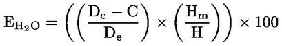
where:
|
D e |
is the expected diluted NO concentration [ppm] |
|
C |
is the measured diluted NO concentration [ppm] |
|
H m |
is the maximum water vapour concentration [%] |
|
H |
is the actual water vapour concentration [%]. |
(iii) Maximum allowable quench
The combined CO2 and water quench shall not exceed 2 per cent of full scale.
(d) Quench check for NDUV analysers
Hydrocarbons and water can positively interfere with NDUV analysers by causing a response similar to that of NOX. The manufacturer of the NDUV analyser shall use the following procedure to verify that quench effects are limited:
(i) The analyser and chiller shall be set up by following the operating instructions of the manufacturer; adjustments should be made as to optimise the analyser and chiller performance.
(ii) A zero calibration and span calibration at concentration values expected during emissions testing shall be performed for the analyser.
(iii) A NO2 calibration gas shall be selected that matches as far as possible the maximum NO2 concentration expected during emissions testing.
(iv) The NO2 calibration gas shall overflow at the gas sampling system's probe until the NOX response of the analyser has stabilised.
(v) The mean concentration of the stabilised NOX recordings over a period of 30 s shall be calculated and recorded as NOX,ref.
(vi) The flow of the NO2 calibration gas shall be stopped and the sampling system saturated by overflowing with a dew point generator's output, set at a dew point of 50 °C. The dew point generator's output shall be sampled through the sampling system and chiller for at least 10 minutes until the chiller is expected to be removing a constant rate of water.
(vii) Upon completion of (iv), the sampling system shall again be overflown by the NO2 calibration gas used to establish NOX,ref until the total NOX response has stabilised.
(viii) The mean concentration of the stabilised NOX recordings over a period of 30 s shall be calculated and recorded as NOX,m.
(ix) NOX,m shall be corrected to NOX,dry based upon the residual water vapour that passed through the chiller at the chiller's outlet temperature and pressure.
The calculated NOX,dry shall at least amount to 95 % of NOX,ref.
(e) Sample dryer
A sample dryer removes water, which can otherwise interfere with the NOX measurement. For dry CLD analysers, it shall be demonstrated that at the highest expected water vapour concentration H m the sample dryer maintains the CLD humidity at ≤ 5 g water/kg dry air (or about 0,8 per cent H2O), which is 100 per cent relative humidity at 3,9 °C and 101,3 kPa or about 25 per cent relative humidity at 25 °C and 101,3 kPa. Compliance may be demonstrated by measuring the temperature at the outlet of a thermal sample dryer or by measuring the humidity at a point just upstream of the CLD. The humidity of the CLD exhaust might also be measured as long as the only flow into the CLD is the flow from the sample dryer.
(f) Sample dryer NO2 penetration
Liquid water remaining in an improperly designed sample dryer can remove NO2 from the sample. If a sample dryer is used in combination with a NDUV analyser without an NO2/NO converter upstream, water could therefore remove NO2 from the sample prior to the NOX measurement. The sample dryer shall allow for measuring at least 95 per cent of the NO2 contained in a gas that is saturated with water vapour and consists of the maximum NO2 concentration expected to occur during a vehicle test.
4.4. Response time check of the analytical system
For the response time check, the settings of the analytical system shall be exactly the same as during the emissions test (i.e. pressure, flow rates, filter settings in the analysers and all other parameters influencing the response time). The response time shall be determined with gas switching directly at the inlet of the sample probe. The gas switching shall be done in less than 0,1 second. The gases used for the test shall cause a concentration change of at least 60 per cent full scale of the analyser.
The concentration trace of each single gas component shall be recorded. The delay time is defined as the time from the gas switching (t 0) until the response is 10 per cent of the final reading (t 10). The rise time is defined as the time between 10 per cent and 90 per cent response of the final reading (t 90 – t 10). The system response time (t 90) consists of the delay time to the measuring detector and the rise time of the detector.
For time alignment of the analyser and exhaust flow signals, the transformation time is defined as the time from the change (t 0) until the response is 50 per cent of the final reading (t 50).
The system response time shall be ≤ 12 s with a rise time of ≤ 3 seconds for all components and all ranges used. When using a NMC for the measurement of NMHC, the system response time may exceed 12 seconds.
5. GASES
5.1. General
The shelf life of calibration and span gases shall be respected. Pure and mixed calibration and span gases shall fulfil the specifications of points 3.1 and 3.2 of Appendix 3 of Annex 4A to UN/ECE Regulation No 83, 07 series of amendments. In addition, NO2 calibration gas is permissible. The concentration of the NO2 calibration gas shall be within two per cent of the declared concentration value. The amount of NO contained in NO2 calibration gas shall not exceed 5 per cent of the NO2 content.
5.2. Gas dividers
Gas dividers, i.e. precision blending devices that dilute with purified N2 or synthetic air, can be used to obtain calibration and span gases. The accuracy of the gas divider shall be such that the concentration of the blended calibration gases is accurate to within ± 2 per cent. The verification shall be performed at between 15 and 50 per cent of full scale for each calibration incorporating a gas divider. An additional verification may be performed using another calibration gas, if the first verification has failed.
Optionally, the gas divider may be checked with an instrument which by nature is linear, e.g. using NO gas in combination with a CLD. The span value of the instrument shall be adjusted with the span gas directly connected to the instrument. The gas divider shall be checked at the settings typically used and the nominal value shall be compared with the concentration measured by the instrument. The difference shall in each point be within ± 1 per cent of the nominal concentration value.
5.3. Oxygen interference check gases
Oxygen interference check gases consist of a blend of propane, oxygen and nitrogen and shall contain propane at a concentration of 350 ± 75 ppmC1. The concentration shall be determined by gravimetric methods, dynamic blending or the chromatographic analysis of total hydrocarbons plus impurities. The oxygen concentrations of the oxygen interference check gases shall meet the requirements listed in Table 3; the remainder of the oxygen interference check gas shall consist of purified nitrogen.
Table 3
Oxygen interference check gases
|
|
Engine type |
|
|
Compression ignition |
Positive ignition |
|
|
O2 concentration |
21 ± 1 % |
10 ± 1 % |
|
10 ± 1 % |
5 ± 1 % |
|
|
5 ± 1 % |
0,5 ± 0,5 % |
|
6. ANALYSERS FOR MEASURING PARTICLE EMISSIONS
This section will define future requirements for analysers for measuring particle emissions, once their measurement becomes mandatory.
7. INSTRUMENTS FOR MEASURING EXHAUST MASS FLOW
7.1. General
Instruments, sensors or signals for measuring the exhaust mass flow rate shall have a measuring range and response time appropriate for the accuracy required to measure the exhaust mass flow rate under transient and steady state conditions. The sensitivity of instruments, sensors and signals to shocks, vibration, aging, variability in temperature, ambient air pressure, electromagnetic interferences and other impacts related to vehicle and instrument operation shall be on a level as to minimise additional errors.
7.2. Instrument specifications
The exhaust mass flow rate shall be determined by a direct measurement method applied in either of the following instruments:
(a) Pitot-based flow devices;
(b) pressure differential devices like flow nozzle (details see ISO 5167);
(c) ultrasonic flow meter;
(d) vortex flow meter.
Each individual exhaust mass flow meter shall fulfil the linearity requirements set out in point 3. Furthermore, the instrument manufacturer shall demonstrate the compliance of each type of exhaust mass flow meter with the specifications in points 7.2.3 to 7.2.9.
It is permissible to calculate the exhaust mass flow rate based on air flow and fuel flow measurements obtained from traceably calibrated sensors if these fulfil the linearity requirements of point 3, the accuracy requirements of point 8 and if the resulting exhaust mass flow rate is validated according to point 4 of Appendix 3.
In addition, other methods that determine the exhaust mass flow rate based on not directly traceable instruments and signals, such as simplified exhaust mass flow meters or ECU signals are permissible if the resulting exhaust mass flow rate fulfils the linearity requirements of point 3 and is validated according to point 4 of Appendix 3.
7.2.1. Calibration and verification standards
The measurement performance of exhaust mass flow meters shall be verified with air or exhaust gas against a traceable standard such as, e.g. a calibrated exhaust mass flow meter or a full flow dilution tunnel.
7.2.2. Frequency of verification
The compliance of exhaust mass flow meters with points 7.2.3 and 7.2.9 shall be verified no longer than one year before the actual test.
7.2.3. Accuracy
The accuracy, defined as the deviation of the EFM reading from the reference flow value, shall not exceed ± 2 % of the reading, 0,5 % of full scale or ± 1,0 % of the maximum flow at which the EFM has been calibrated, whichever is larger.
7.2.4. Precision
The precision, defined as 2,5 times the standard deviation of 10 repetitive responses to a given nominal flow, approximately in the middle of the calibration range, shall be no greater than ±1 per cent of the maximum flow at which the EFM has been calibrated.
7.2.5. Noise
The noise, defined as two times the root mean square of ten standard deviations, each calculated from the zero responses measured at a constant recording frequency of at least 1,0 Hz during a period of 30 seconds, shall not exceed 2 per cent of the maximum calibrated flow value. Each of the 10 measurement periods shall be interspersed with an interval of 30 seconds in which the EFM is exposed to the maximum calibrated flow.
7.2.6. Zero response drift
Zero response is defined as the mean response to zero flow during a time interval of at least 30 seconds. The zero response drift can be verified based on the reported primary signals, e.g. pressure. The drift of the primary signals over a period of 4 hours shall be less than ± 2 per cent of the maximum value of the primary signal recorded at the flow at which the EFM was calibrated.
7.2.7. Span response drift
Span response is defined as the mean response to a span flow during a time interval of at least 30 seconds. The span response drift can be verified based on the reported primary signals, e.g. pressure. The drift of the primary signals over a period of 4 hours shall be less than ± 2 per cent of the maximum value of the primary signal recorded at the flow at which the EFM was calibrated.
7.2.8. Rise time
The rise time of the exhaust flow instruments and methods should match as far as possible the rise time of the gas analysers as specified in point 4.2.7 but shall not exceed 1 second.
7.2.9. Response time check
The response time of exhaust mass flow meters shall be determined by applying similar parameters as those applied for the emissions test (i.e. pressure, flow rates, filter settings and all other response time influences). The response time determination shall be done with gas switching directly at the inlet of the exhaust mass flow meter. The gas flow switching shall be done as fast as possible, but highly recommended in less than 0,1 second. The gas flow rate used for the test shall cause a flow rate change of at least 60 per cent full scale (FS) of the exhaust mass flow meter. The gas flow shall be recorded. The delay time is defined as the time from the gas flow switching (t 0) until the response is 10 per cent (t 10) of the final reading. The rise time is defined as the time between 10 per cent and 90 per cent response (t 90 – t 10) of the final reading. The response time (t 90) is defined as the sum of the delay time and the rise time. The exhaust mass flow meter response time (t90 ) shall be ≤ 3 seconds with a rise time (t 90 – t 10) of ≤ 1 second in accordance with point 7.2.8.
8. SENSORS AND AUXILIARY EQUIPMENT
Any sensor and auxiliary equipment used to determine, e.g. temperature, atmospheric pressure, ambient humidity, vehicle speed, fuel flow or intake air flow shall not alter or unduly affect the performance of the vehicle's engine and exhaust after-treatment system. The accuracy of sensors and auxiliary equipment shall fulfil the requirements of Table 4. Compliance with the requirements of Table 4 shall be demonstrated at intervals specified by the instrument manufacturer, as required by internal audit procedures or in accordance with ISO 9000.
Table 4
Accuracy requirements for measurement parameters
|
Measurement parameter |
Accuracy |
|
Fuel flow (1) |
± 1 % of reading (3) |
|
Air flow (1) |
± 2 % of reading |
|
Vehicle ground speed (2) |
± 1,0 km/h absolute |
|
Temperatures ≤ 600 K |
± 2 K absolute |
|
Temperatures >600 K |
± 0,4 % of reading in Kelvin |
|
Ambient pressure |
± 0,2 kPa absolute |
|
Relative humidity |
± 5 % absolute |
|
Absolute humidity |
± 10 % of reading or, 1 gH2O/kg dry air, whichever is larger |
|
(1) Optional to determine exhaust mass flow. (2) The requirement applies to the speed sensor only. (3) The accuracy shall be 0,02 per cent of reading if used to calculate the air and exhaust mass flow rate from the fuel flow according to point 10 of Appendix 4. |
|
Appendix 3
Validation of PEMS and non-traceable exhaust mass flow rate
1. INTRODUCTION
This appendix describes the requirements to validate under transient conditions the functionality of the installed PEMS as well as the correctness of the exhaust mass flow rate obtained from non-traceable exhaust mass flow meters or calculated from ECU signals.
2. SYMBOLS
|
% |
— |
per cent |
|
#/km |
— |
number per kilometre |
|
a 0 |
— |
y intercept of the regression line |
|
a 1 |
— |
slope of the regression line |
|
g/km |
— |
gramme per kilometre |
|
Hz |
— |
hertz |
|
km |
— |
kilometre |
|
m |
— |
metre |
|
mg/km |
— |
milligramme per kilometre |
|
r2 |
— |
coefficient of determination |
|
x |
— |
actual value of the reference signal |
|
y |
— |
actual value of the signal under validation |
3. VALIDATION PROCEDURE FOR PEMS
3.1. Frequency of PEMS validation
It is recommended to validate the installed PEMS once for each PEMS-vehicle combination either before the test or, alternatively, after the completion of an on-road test. The PEMS installation shall be kept unchanged in the time period between the on-road test and the validation.
3.2. PEMS validation procedure
3.2.1. PEMS installation
The PEMS shall be installed and prepared according to the requirements of Appendix 1. After the completion of the validation test until the start of the on-road test, the PEMS installation shall not be changed.
3.2.2. Test conditions
The validation test shall be conducted on a chassis dynamometer, as far as applicable, under type-approval conditions by following the requirements of Annex 4a to UN/ECE Regulation No 83, 07 series of amendments or any other adequate measurement method. It is recommended to conduct the validation test with the worldwide harmonised light vehicles test cycle (WLTC) as specified in Annex 1 to UNECE Global Technical Regulation No 15. The ambient temperature shall be within the range specified in point 5.2 of this Annex.
It is recommended to feed the exhaust flow extracted by the PEMS during the validation test back to the CVS. If this is not feasible, the CVS results shall be corrected for the extracted exhaust mass. If the exhaust mass flow rate is validated with an exhaust mass flow meter, it is recommended to cross-check the mass flow rate measurements with data obtained from a sensor or the ECU.
3.2.3. Data analysis
The total distance-specific emissions [g/km] measured with laboratory equipment shall be calculated following Annex 4a to UN/ECE Regulation No 83, 07 series of amendments. The emissions as measured with the PEMS shall be calculated according to point 9 of Appendix 4, summed to give the total mass of pollutant emissions [g] and then divided by the test distance [km] as obtained from the chassis dynamometer. The total distance-specific mass of pollutants [g/km], as determined by the PEMS and the reference laboratory system, shall be compared and evaluated against the requirements specified in point 3.3. For the validation of NOX emission measurements, humidity correction shall be applied following point 6.6.5 of Annex 4a to UN/ECE Regulation No 83, 07 series of amendments.
3.3. Permissible tolerances for PEMS validation
The PEMS validation results shall fulfil the requirements given in Table 1. If any permissible tolerance is not met, corrective action shall be taken and the PEMS validation shall be repeated.
Table 1
Permissible tolerances
|
Parameter [Unit] |
Permissible tolerance |
|
Distance [km] (1) |
± 250 m of the laboratory reference |
|
THC (2) [mg/km] |
± 15 mg/km or 15 % of the laboratory reference, whichever is larger |
|
CH4 (2) [mg/km] |
± 15 mg/km or 15 % of the laboratory reference, whichever is larger |
|
NMHC (2) [mg/km] |
± 20 mg/km or 20 % of the laboratory reference, whichever is larger |
|
PN (2) [#/km] |
|
|
CO (2) [mg/km] |
± 150 mg/km or 15 % of the laboratory reference, whichever is larger |
|
CO2 [g/km] |
± 10 g/km or 10 % of the laboratory reference, whichever is larger |
|
NOx (2) [mg/km] |
± 15 mg/km or 15 % of the laboratory reference, whichever is larger |
|
(1) Only applicable if vehicle speed is determined by the ECU; to meet the permissible tolerance it is permitted to adjust the ECU vehicle speed measurements based on the outcome of the validation test. (2) Parameter only mandatory if measurement required by Annex IIIA, Section 2.1. (3) Still to be determined. |
|
4. VALIDATION PROCEDURE FOR THE EXHAUST MASS FLOW RATE DETERMINED BY NON-TRACEABLE INSTRUMENTS AND SENSORS
4.1. Frequency of validation
In addition to fulfilling the linearity requirements of point 3 of Appendix 2 under steady-state conditions, the linearity of non-traceable exhaust mass flow meters or the exhaust mass flow rate calculated from non-traceable sensors or ECU signals shall be validated under transient conditions for each test vehicle against a calibrated exhaust mass flow meter or the CVS. The validation test procedure can be executed without the installation of the PEMS but shall generally follow the requirements defined in Annex 4a to UN/ECE Regulation No 83, 07 series of amendments and the requirements pertinent to exhaust mass flow meters defined in Appendix 1.
4.2. Validation procedure
The validation test shall be conducted on a chassis dynamometer under type-approval conditions, as far as applicable, by following the requirements of Annex 4a to UN/ECE Regulation No 83, 07 series of amendments. The test cycle shall be the worldwide harmonised light vehicles test cycle (WLTC) as specified in Annex 1 to UNECE Global Technical Regulation No 15. As reference, a traceably calibrated flow meter shall be used. The ambient temperature can be any within the range specified in point 5.2 of this Annex. The installation of the exhaust mass flow meter and the execution of the test shall fulfil the requirement of point 3.4.3 of Appendix 1 of this Annex.
The following calculation steps shall be taken to validate the linearity:
(a) The signal under validation and the reference signal shall be time corrected by following, as far as applicable, the requirements of point 3 of Appendix 4.
(b) Points below 10 % of the maximum flow value shall be excluded from the further analysis.
(c) At a constant frequency of at least 1,0 Hz, the signal under validation and the reference signal shall be correlated using the best-fit equation having the form:
y = a 1 x + a 0
where:
|
y |
is the actual value of the signal under validation |
|
a 1 |
is the slope of the regression line |
|
x |
is the actual value of the reference signal |
|
a 0 |
is the y intercept of the regression line |
The standard error of estimate (SEE) of y on x and the coefficient of determination (r2) shall be calculated for each measurement parameter and system.
(d) The linear regression parameters shall meet the requirements specified in Table 2.
4.3. Requirements
The linearity requirements given in Table 2 shall be fulfilled. If any permissible tolerance is not met, corrective action shall be taken and the validation shall be repeated.
Table 2
Linearity requirements of calculated and measured exhaust mass flow
|
Measurement parameter/system |
a0 |
Slope a1 |
Standard error SEE |
Coefficient of determination r2 |
|
Exhaust mass flow |
0,0 ± 3,0 kg/h |
1,00 ± 0,075 |
≤ 10 % max |
≥ 0,90 |
Appendix 4
Determination of emissions
1. INTRODUCTION
This appendix describes the procedure to determine the instantaneous mass and particle number emissions [g/s; #/s] that shall be used for the subsequent evaluation of a test trip and the calculation of the final emission result as described in Appendices 5 and 6.
2. SYMBOLS
|
% |
— |
per cent |
|
< |
— |
smaller than |
|
#/s |
— |
number per second |
|
α |
— |
molar hydrogen ratio (H/C) |
|
β |
— |
molar carbon ratio (C/C) |
|
γ |
— |
molar sulphur ratio (S/C) |
|
δ |
— |
molar nitrogen ratio (N/C) |
|
Δtt,i |
— |
transformation time t of the analyser [s] |
|
Δtt,m |
— |
transformation time t of the exhaust mass flow meter [s] |
|
ε |
— |
molar oxygen ratio (O/C) |
|
r e |
— |
density of the exhaust |
|
r gas |
— |
density of the exhaust component ‘gas’ |
|
l |
— |
excess air ratio |
|
l i |
— |
instantaneous excess air ratio |
|
A/F st |
— |
stoichiometric air-to-fuel ratio [kg/kg] |
|
°C |
— |
degrees centigrade |
|
c CH4 |
— |
concentration of methane |
|
c CO |
— |
dry CO concentration [%] |
|
c CO2 |
— |
dry CO2 concentration [%] |
|
c dry |
— |
dry concentration of a pollutant in ppm or per cent volume |
|
c gas,i |
— |
instantaneous concentration of the exhaust component ‘gas’ [ppm] |
|
c HCw |
— |
wet HC concentration [ppm] |
|
c HC(w/NMC) |
— |
HC concentration with CH4 or C2H6 flowing through the NMC [ppmC1] |
|
c HC(w/oNMC) |
— |
HC concentration with CH4 or C2H6 bypassing the NMC [ppmC1] |
|
c i,c |
— |
time-corrected concentration of component i [ppm] |
|
c i,r |
— |
concentration of component i [ppm] in the exhaust |
|
c NMHC |
— |
concentration of non-methane hydrocarbons |
|
c wet |
— |
wet concentration of a pollutant in ppm or per cent volume |
|
E E |
— |
ethane efficiency |
|
E M |
— |
methane efficiency |
|
g |
— |
gramme |
|
g/s |
— |
gramme per second |
|
H a |
— |
intake air humidity [g water per kg dry air] |
|
i |
— |
number of the measurement |
|
kg |
— |
kilogram |
|
kg/h |
— |
kilogramme per hour |
|
kg/s |
— |
kilogramme per second |
|
k w |
— |
dry-wet correction factor |
|
m |
— |
metre |
|
m gas,i |
— |
mass of the exhaust component ‘gas’ [g/s] |
|
qm aw,i |
— |
instantaneous intake air mass flow rate [kg/s] |
|
q m,c |
— |
time-corrected exhaust mass flow rate [kg/s] |
|
qm ew,i |
— |
instantaneous exhaust mass flow rate [kg/s] |
|
qm f,i |
— |
instantaneous fuel mass flow rate [kg/s] |
|
q m,r |
— |
raw exhaust mass flow rate [kg/s] |
|
r |
— |
cross-correlation coefficient |
|
r2 |
— |
coefficient of determination |
|
r h |
— |
hydrocarbon response factor |
|
rpm |
— |
revolutions per minute |
|
s |
— |
second |
|
u gas |
— |
u value of the exhaust component ‘gas’ |
3. TIME CORRECTION OF PARAMETERS
For the correct calculation of distance-specific emissions, the recorded traces of component concentrations, exhaust mass flow rate, vehicle speed, and other vehicle data shall be time corrected. To facilitate the time correction, data which are subject to time alignment shall be recorded either in a single data recording device or with a synchronised timestamp following point 5.1 of Appendix 1. The time correction and alignment of parameters shall be carried out by following the sequence described in points 3.1 to 3.3.
3.1. Time correction of component concentrations
The recorded traces of all component concentrations shall be time corrected by reverse shifting according to the transformation times of the respective analysers. The transformation time of analysers shall be determined according to point 4.4 of Appendix 2:
c i,c (t – Δt t,i ) = c i,r (t)
where:
|
c i,c |
is the time-corrected concentration of component i as function of time t |
|
c i,r |
is the raw concentration of component i as function of time t |
|
Δtt,i |
is the transformation time t of the analyser measuring component i. |
3.2. Time correction of exhaust mass flow rate
The exhaust mass flow rate measured with an exhaust flow meter shall be time corrected by reverse shifting according to the transformation time of the exhaust mass flow meter. The transformation time of the mass flow meter shall be determined according to point 4.4.9 of Appendix 2:
q m,c (t – Δt t,m ) = qm ,r (t)
where:
|
q m,c |
is the time-corrected exhaust mass flow rate as function of time t |
|
q m,r |
is the raw exhaust mass flow rate as function of time t |
|
Δtt,m |
is the transformation time t of the exhaust mass flow meter. |
In case the exhaust mass flow rate is determined by ECU data or a sensor, an additional transformation time shall be considered and obtained by cross-correlation between the calculated exhaust mass flow rate and the exhaust mass flow rate measured following point 4 of Appendix 3.
3.3. Time alignment of vehicle data
Other data obtained from a sensor or the ECU shall be time-aligned by cross-correlation with suitable emission data (e.g. component concentrations).
3.3.1. Vehicle speed from different sources
To time align vehicle speed with the exhaust mass flow rate, it is first necessary to establish one valid speed trace. In case vehicle speed is obtained from multiple sources (e.g. the GPS, a sensor or the ECU), the speed values shall be time aligned by cross-correlation.
3.3.2. Vehicle speed with exhaust mass flow rate
Vehicle speed shall be time aligned with the exhaust mass flow rate by means of cross-correlation between the exhaust mass flow rate and the product of vehicle velocity and positive acceleration.
3.3.3. Further signals
The time alignment of signals whose values change slowly and within a small value range, e.g. ambient temperature, can be omitted.
4. COLD START
The cold start period covers the first 5 minutes after initial start of the combustion engine. If the coolant temperature can be reliably determined, the cold start period ends once the coolant has reached 343 K (70 °C) for the first time but no later than 5 minutes after initial engine start. Cold start emissions shall be recorded.
5. EMISSION MEASUREMENTS DURING ENGINE STOP
Any instantaneous emissions or exhaust flow measurements obtained while the combustion engine is deactivated shall be recorded. In a separate step, the recorded values shall afterward be set to zero by the data post processing. The combustion engine shall be considered as deactivated if two of the following criteria apply: the recorded engine speed is < 50 rpm; the exhaust mass flow rate is measured at < 3 kg/h; the measured exhaust mass flow rate drops to < 15 % of the steady-state exhaust mass flow rate at idling.
6. CONSISTENCY CHECK OF VEHICLE ALTITUDE
In case well-reasoned doubts exist that a trip has been conducted above of the permissible altitude as specified in point 5.2 of Annex IIIA and in case altitude has only been measured with a GPS, the GPS altitude data shall be checked for consistency and, if necessary, corrected. The consistency of data shall be checked by comparing the latitude, longitude and altitude data obtained from the GPS with the altitude indicated by a digital terrain model or a topographic map of suitable scale. Measurements that deviate by more than 40 m from altitude depicted in the topographic map shall be manually corrected and marked.
7. CONSISTENCY CHECK OF GPS VEHICLE SPEED
The vehicle speed as determined by the GPS shall be checked for consistency by calculating and comparing the total trip distance with reference measurements obtained from either a sensor, the validated ECU or, alternatively, from a digital road network or topographic map. It is mandatory to correct GPS data for obvious errors, e.g. by applying a dead reckoning sensor, prior to the consistency check. The original and uncorrected data file shall be retained and any corrected data shall be marked. The corrected data shall not exceed an uninterrupted time period of 120 s or a total of 300 s. The total trip distance as calculated from the corrected GPS data shall deviate by no more than 4 % from the reference. If the GPS data do not meet these requirements and no other reliable speed source is available, the test results shall be voided.
8. CORRECTION OF EMISSIONS
8.1. Dry-wet correction
If the emissions are measured on a dry basis, the measured concentrations shall be converted to a wet basis as:
c wet= k w· c dry
where:
|
c wet |
is the wet concentration of a pollutant in ppm or per cent volume |
|
c dry |
is the dry concentration of a pollutant in ppm or per cent volume |
|
k w |
is the dry-wet correction factor |
The following equation shall be used to calculate k w:
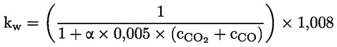
where:

where:
|
H a |
is the intake air humidity [g water per kg dry air] |
|
c CO2 |
is the dry CO2 concentration [%] |
|
c CO |
is the dry CO concentration [%] |
|
α |
is the molar hydrogen ratio. |
8.2. Correction of NOx for ambient humidity and temperature
NOx emissions shall not be corrected for ambient temperature and humidity.
9. DETERMINATION OF THE INSTANTANEOUS GASEOUS EXHAUST COMPONENTS
9.1. Introduction
The components in the raw exhaust gas shall be measured with the measurement and sampling analysers described in Appendix 2. The raw concentrations of relevant components shall be measured in accordance with Appendix 1. The data shall be time corrected and aligned in accordance with point 3.
9.2. Calculating NMHC and CH4 concentrations
For methane measurement using a NMC-FID, the calculation of NMHC depends on the calibration gas/method used for the zero/span calibration adjustment. When a FID is used for THC measurement without a NMC, it shall be calibrated with propane/air or propane/N2 in the normal manner. For the calibration of the FID in series with a NMC, the following methods are permitted:
(a) the calibration gas consisting of propane/air bypasses the NMC;
(b) the calibration gas consisting of methane/air passes through the NMC.
It is strongly recommended to calibrate the methane FID with methane/air through the NMC.
In method (a), the concentrations of CH4 and NMHC shall be calculated as follows:
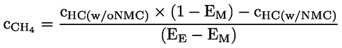

In case (b), the concentration of CH4 and NMHC shall be calculated as follows:
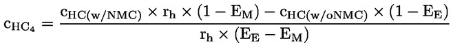
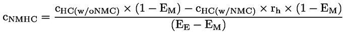
where:
|
c HC(w/oNMC) |
is the HC concentration with CH4 or C2H6 bypassing the NMC [ppmC1] |
|
c HC(w/NMC) |
is the HC concentration with CH4 or C2H6 flowing through the NMC [ppmC1] |
|
r h |
is the hydrocarbon response factor as determined in point 4.3.3(b) of Appendix 2 |
|
E M |
is the methane efficiency as determined in point 4.3.4(a) of Appendix 2 |
|
E E |
is the ethane efficiency as determined in point 4.3.4(b) of Appendix 2. |
If the methane FID is calibrated through the cutter (method b), then the methane conversion efficiency as determined in point 4.3.4(a) of Appendix 2 is zero. The density used for NMHC mass calculations shall be equal to that of total hydrocarbons at 273,15 K and 101,325 kPa and is fuel-dependent.
10. DETERMINATION OF EXHAUST MASS FLOW
10.1. Introduction
The calculation of instantaneous mass emissions according to points 11 and 12 requires determining the exhaust mass flow rate. The exhaust mass flow rate shall be determined by one of the direct measurement methods specified in point 7.2 of Appendix 2. Alternatively, it is permissible to calculate the exhaust mass flow rate as described in points 10.2 to 10.4.
10.2. Calculation method using air mass flow rate and fuel mass flow rate
The instantaneous exhaust mass flow rate can be calculated from the air mass flow rate and the fuel mass flow rate as follows:
q mew,i = q maw,i + q mf,i
where:
|
qm ew,i |
is the instantaneous exhaust mass flow rate [kg/s] |
|
qm aw,i |
is the instantaneous intake air mass flow rate [kg/s] |
|
qm f,i |
is the instantaneous fuel mass flow rate [kg/s]. |
If the air mass flow rate and the fuel mass flow rate or the exhaust mass flow rate are determined from ECU recording, the calculated instantaneous exhaust mass flow rate shall meet the linearity requirements specified for the exhaust mass flow rate in point 3 of Appendix 2 and the validation requirements specified in point 4.3 of Appendix 3.
10.3. Calculation method using air mass flow and air-to-fuel ratio
The instantaneous exhaust mass flow rate can be calculated from the air mass flow rate and the air-to-fuel ratio as follows:
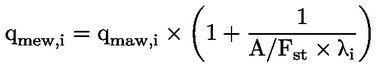
where:


where:
|
qm aw,i |
is the instantaneous intake air mass flow rate [kg/s] |
|
A/F st |
is the stoichiometric air-to-fuel ratio [kg/kg] |
|
l i |
is the instantaneous excess air ratio |
|
c CO2 |
is the dry CO2 concentration [%] |
|
c CO |
is the dry CO concentration [ppm] |
|
c HCw |
is the wet HC concentration [ppm] |
|
α |
is the molar hydrogen ratio (H/C) |
|
β |
is the molar carbon ratio (C/C) |
|
γ |
is the molar sulphur ratio (S/C) |
|
δ |
is the molar nitrogen ratio (N/C) |
|
ε |
is the molar oxygen ratio (O/C). |
Coefficients refer to a fuel Cβ Hα Oε Nδ Sγ with β = 1 for carbon-based fuels. The concentration of HC emissions is typically low and may be omitted when calculating l i.
If the air mass flow rate and air-to-fuel ratio are determined from ECU recording, the calculated instantaneous exhaust mass flow rate shall meet the linearity requirements specified for the exhaust mass flow rate in point 3 of Appendix 2 and the validation requirements specified in point 4.3 of Appendix 3.
10.4. Calculation method using fuel mass flow and air-to-fuel ratio
The instantaneous exhaust mass flow rate can be calculated from the fuel flow and the air-to-fuel ratio (calculated with A/Fst and l i according to point 10.3) as follows:
q mew,i = q mf,i × (1 + A/F st × λ i)
The calculated instantaneous exhaust mass flow rate shall meet the linearity requirements specified for the exhaust gas mass flow rate in point 3 of Appendix 2 and the validation requirements specified in point 4.3 of Appendix 3.
11. CALCULATING THE INSTANTANEOUS MASS EMISSIONS
The instantaneous mass emissions [g/s] shall be determined by multiplying the instantaneous concentration of the pollutant under consideration [ppm] with the instantaneous exhaust mass flow rate [kg/s], both corrected and aligned for the transformation time, and the respective u value of Table 1. If measured on a dry basis, the dry-wet correction according to point 8.1 shall be applied to the instantaneous component concentrations before executing any further calculations. If applicable, negative instantaneous emission values shall enter all subsequent data evaluations. All significant digits of intermediate results shall enter the calculation of the instantaneous emissions. The following equation shall be applied:
m gas,i = u gas · c gas,i · q mew,i
where:
|
m gas,i |
is the mass of the exhaust component ‘gas’ [g/s] |
|
u gas |
is the ratio of the density of the exhaust component ‘gas’ and the overall density of the exhaust as listed in Table 1 |
|
c gas,i |
is the measured concentration of the exhaust component ‘gas’ in the exhaust [ppm] |
|
qm ew,i |
is the measured exhaust mass flow rate [kg/s] |
|
gas |
is the respective component |
|
i |
number of the measurement. |
Table 1
Raw exhaust gas u values depicting the ratio between the densities of exhaust component or pollutant [kg/m3] and the density of the exhaust gas [kg/m3] (6)
|
Fuel |
ρ e [kg/m3] |
Component or pollutant i |
|||||
|
NOx |
CO |
HC |
CO2 |
O2 |
CH4 |
||
|
ρ gas [kg/m3] |
|||||||
|
2,053 |
1,250 |
1,9636 |
1,4277 |
0,716 |
|||
|
Diesel (B7) |
1,2943 |
0,001586 |
0,000966 |
0,000482 |
0,001517 |
0,001103 |
0,000553 |
|
Ethanol (ED95) |
1,2768 |
0,001609 |
0,000980 |
0,000780 |
0,001539 |
0,001119 |
0,000561 |
|
CNG (3) |
1,2661 |
0,001621 |
0,000987 |
0,000528 (4) |
0,001551 |
0,001128 |
0,000565 |
|
Propane |
1,2805 |
0,001603 |
0,000976 |
0,000512 |
0,001533 |
0,001115 |
0,000559 |
|
Butane |
1,2832 |
0,001600 |
0,000974 |
0,000505 |
0,001530 |
0,001113 |
0,000558 |
|
LPG (5) |
1,2811 |
0,001602 |
0,000976 |
0,000510 |
0,001533 |
0,001115 |
0,000559 |
|
Petrol (E10) |
1,2931 |
0,001587 |
0,000966 |
0,000499 |
0,001518 |
0,001104 |
0,000553 |
|
Ethanol (E85) |
1,2797 |
0,001604 |
0,000977 |
0,000730 |
0,001534 |
0,001116 |
0,000559 |
|
(1) Depending on fuel. (2) At l = 2, dry air, 273 K, 101,3 kPa. (3) u values accurate within 0,2 % for mass composition of: C = 66 – 76 %; H = 22 – 25 %; N = 0 – 12 %. (4) NMHC on the basis of CH2,93 (for THC the u gas coefficient of CH4 shall be used). (5) u accurate within 0,2 % for mass composition of: C3 = 70 – 90 %; C4 = 10 – 30 %. (6) ugas is a unitless parameter; the u gas values include unit conversions to ensure that the instantaneous emissions are obtained in the specified physical unit, i.e. g/s. |
|||||||
12. CALCULATING THE INSTANTANEOUS PARTICLE NUMBER EMISSIONS
This section will define future requirements for calculating instantaneous particle number emissions, once their measurement becomes mandatory.
13. DATA REPORTING AND EXCHANGE
The data shall be exchanged between the measurement systems and the data evaluation software by a standardised reporting file as specified in point 2 of Appendix 8. Any pre-processing of data (e.g. time correction according to point 3 or the correction of the GPS vehicle speed signal according to point 7) shall be done with the control software of the measurement systems and shall be completed before the data reporting file is generated. If data are corrected or processed prior to entering the data reporting file, the original raw data shall be kept for quality assurance and control. Rounding of intermediate values is not permitted. Instead, intermediate values shall enter the calculation of instantaneous emissions [g/s; #/s] as reported by the analyser, flow-measuring instrument, sensor or the ECU.
Appendix 5
Verification of trip dynamic conditions with method 1 (Moving Averaging Window)
1. INTRODUCTION
The Moving Averaging Window method provides an insight on the real-driving emissions (RDE) occurring during the test at a given scale. The test is divided in sub-sections (windows) and the subsequent statistical treatment aims at identifying which windows are suitable to assess the vehicle RDE performance.
The ‘normality’ of the windows is conducted by comparing their CO2 distance-specific emissions ( 55 ) with a reference curve. The test is complete when the test includes a sufficient number of normal windows, covering different speed areas (urban, rural, motorway).
|
Step 1. |
Segmentation of the data and exclusion of cold start emissions; |
|
Step 2. |
Calculation of emissions by sub-sets or ‘windows’ (point 3.1); |
|
Step 3. |
Identification of normal windows; (point 4) |
|
Step 4. |
Verification of test completeness and normality (point 5); |
|
Step 5. |
Calculation of emissions using the normal windows (point 6). |
2. SYMBOLS, PARAMETERS AND UNITS
Index (i) refers to the time step
Index (j) refers to the window
Index (k) refers to the category (t=total, u=urban, r=rural, m=motorway) or to the CO2 characteristic curve (cc)
Index ‘gas’ refers to the regulated exhaust gas components (e.g. NOx, CO, PN)
|
Δ |
— |
difference |
|
≥ |
— |
larger or equal |
|
# |
— |
number |
|
% |
— |
per cent |
|
≤ |
— |
smaller or equal |
|
a 1, b 1 |
— |
coefficients of the CO2 characteristic curve |
|
a 2, b 2 |
— |
coefficients of the CO2 characteristic curve |
|
dj |
— |
distance covered by window j [km] |
|
fk |
— |
weighing factors for urban, rural and motorway shares |
|
h |
— |
distance of windows to the CO2 characteristic curve [%] |
|
hj |
— |
distance of window j to the CO2 characteristic curve [%] |
|
|
— |
severity index for urban, rural and motorway shares and the complete trip |
|
k 11, k 12 |
— |
coefficients of the weighing function |
|
k 21, k 21 |
— |
coefficients of the weighing function |
|
M CO2,ref |
— |
reference CO2 mass [g] |
|
Mgas |
— |
mass or particle number of the exhaust component ‘gas’ [g] or [#] |
|
Mgas,j |
— |
mass or particle number of the exhaust component ‘gas’ in window j [g] or [#] |
|
Mgas,d |
— |
distance-specific emission for the exhaust component ‘gas’ [g/km] or [#/km] |
|
Mgas,d,j |
— |
distance-specific emission for the exhaust component ‘gas’ in window j [g/km] or [#/km] |
|
N k |
— |
number of windows for urban, rural, and motorway shares |
|
P 1, P 2, P 3 |
— |
reference points |
|
t |
— |
time [s] |
|
t 1,j |
— |
first second of the jth averaging window [s] |
|
t 2,j |
— |
last second of the jth averaging window [s] |
|
ti |
— |
total time in step i [s] |
|
t i,j |
— |
total time in step i considering window j [s] |
|
tol 1 |
— |
primary tolerance for the vehicle CO2 characteristic curve [%] |
|
tol 2 |
— |
secondary tolerance for the vehicle CO2 characteristic curve [%] |
|
tt |
— |
duration of a test [s] |
|
v |
— |
vehicle speed [km/h] |
|
|
— |
average speed of windows [km/h] |
|
vi |
— |
actual vehicle speed in time step i [km/h] |
|
|
— |
average vehicle speed in window j [km/h] |
|
|
— |
average speed of the Low Speed phase of the WLTP cycle |
|
|
— |
average speed of the High Speed phase of the WLTP cycle |
|
|
— |
average speed of the Extra High Speed phase of the WLTP cycle |
|
w |
— |
weighing factor for windows |
|
wj |
— |
weighing factor of window j. |
3. MOVING AVERAGING WINDOWS
3.1. Definition of averaging windows
The instantaneous emissions calculated according to Appendix 4 shall be integrated using a moving averaging window method, based on the reference CO2 mass. The principle of the calculation is as follows: the mass emissions are not calculated for the complete data set, but for sub-sets of the complete data set, the length of these sub-sets being determined so as to match the CO2 mass emitted by the vehicle over the reference laboratory cycle. The moving average calculations are conducted with a time increment corresponding to the data sampling frequency. These sub-sets used to average the emissions data are referred to as ‘averaging windows’. The calculation described in the present point may be run from the last point (backwards) or from the first point (forward).
The following data shall not be considered for the calculation of the CO2 mass, the emissions and the distance of the averaging windows:
— the periodic verification of the instruments and/or after the zero drift verifications,
— the cold start emissions, defined according to Appendix 4, point 4.4,
— vehicle ground speed < 1 km/h,
— any section of the test during which the combustion engine is switched off.
The mass (or particle number) emissions M gas,j shall be determined by integrating the instantaneous emissions in g/s (or #/s for PN) calculated as specified in Appendix 4.
Figure 1
Vehicle speed versus time — Vehicle averaged emissions versus time, starting from the first averaging window

Figure 2
Definition of CO2 mass based averaging windows

The duration (t2,j – t1,j ) of the jth averaging window is determined by:
![]()
Where:
![]() is the CO2 mass measured between the test start and time (ti,j), [g];
is the CO2 mass measured between the test start and time (ti,j), [g];
![]() is the half of the CO2 mass [g] emitted by the vehicle over the WLTP cycle (Type I test, including cold start);
is the half of the CO2 mass [g] emitted by the vehicle over the WLTP cycle (Type I test, including cold start);
t 2,j shall be selected such as:
![]()
Where Δt is the data sampling period.
The CO2 masses are calculated in the windows by integrating the instantaneous emissions calculated as specified in Appendix 4 to this Annex.
3.2. Calculation of window emissions and averages
The following shall be calculated for each window determined in accordance with point 3.1:
— the distance-specific emissions Mgas,d,j for all the pollutants specified in this annex,
— the distance-specific CO2 emissions MCO2,d,j ,
— the average vehicle speed ![]()
4. EVALUATION OF WINDOWS
4.1. Introduction
The reference dynamic conditions of the test vehicle are set out from the vehicle CO2 emissions versus average speed measured at type approval and referred to as ‘vehicle CO2 characteristic curve’.
To obtain the distance-specific CO2 emissions, the vehicle shall be tested using the road load settings prescribed in the UNECE Global Technical Regulation No 15 — worldwide harmonised light vehicles test procedure (ECE/TRANS/180/Add.15).
4.2. CO2 characteristic curve reference points
The reference points P 1, P 2 and P 3 required to define the curve shall be established as follows:
4.2.1. Point P1
![]()
(average speed of the Low Speed phase of the WLTP cycle)
![]() = Vehicle CO2 emissions over the Low Speed phase of the WLTP cycle × 1,2 [g/km].
= Vehicle CO2 emissions over the Low Speed phase of the WLTP cycle × 1,2 [g/km].
4.2.2. Point P2
|
4.2.3. |
|
|
4.2.4. |
Point P3 |
|
4.2.5. |
|
4.3. CO2 characteristic curve definition
Using the reference points defined in point 4.2, the characteristic curve CO2 emissions are calculated as a function of the average speed using two linear sections (P 1, P 2) and (P 2, P 3). The section (P 2, P 3) is limited to 145 km/h on the vehicle speed axis. The characteristic curve is defined by equations as follows:
For the section (P 1, P 2):
![]()
with:
![]()
and:
![]()
For the section (P 2, P 3):
![]()
with:
![]()
and:
![]()
Figure 3
Vehicle CO2 characteristic curve

4.4. Urban, rural and motorway windows
|
4.4.1. |
Urban windows are characterised by average vehicle ground speeds
|
|
4.4.2. |
Rural windows are characterised by average vehicle ground speeds
|
|
4.4.3. |
Motorway windows are characterised by average vehicle ground speeds
|
Figure 4
Vehicle CO2 characteristic curve: urban, rural and motorway driving definitions
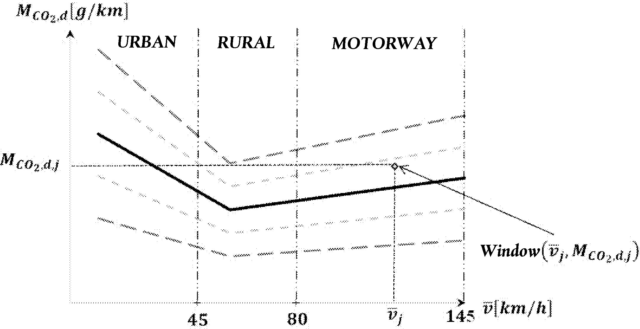
5. VERIFICATION OF TRIP COMPLETENESS AND NORMALITY
5.1. Tolerances around the vehicle CO2 characteristic curve
The primary tolerance and the secondary tolerance of the vehicle CO2 characteristic curve are respectively tol 1= 25 % and tol2 = 50 %.
5.2. Verification of test completeness
The test shall be complete when it comprises at least 15 % of urban, rural and motorway windows, out of the total number of windows.
5.3. Verification of test normality
The test shall be normal when at least 50 % of the urban, rural and motorway windows are within the primary tolerance defined for the characteristic curve.
If the specified minimum requirement of 50 % is not met, the upper positive tolerance tol 1 may be increased by steps of 1 % until the 50 % of normal windows target is reached. When using this mechanism, tol1 shall never exceed 30 %.
6. CALCULATION OF EMISSIONS
6.1. Calculation of weighted distance-specific emissions
The emissions shall be calculated as a weighted average of the windows distance-specific emissions separately for the urban, rural and motorway categories and the complete trip.
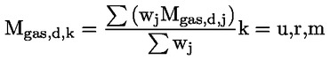
The weighing factor w j for each window shall be determined as such:
If
![]()
Then w j = 1
If

Then wj = k11hj + k12
with k11 = 1/(tol1 – tol2)
and k12: tol2/(tol2– tol1)
If
![]()
Then wj = k21hj + K22
with k21 = 1/(tol2 – tol1)
and k22 = k21 = tol2/(tol2 – tol1)
If
![]()
or
![]()
Then w j = 0
Where:

Figure 5
Averaging window weighing function

6.2. Calculation of severity indices
The severity indices shall be calculated separately for the urban, rural and motorway categories:

and the complete trip:

Where fu, fr fm are equal to 0,34, 0,33 and 0,33 respectively.
6.3. Calculation of emissions for the total trip
Using the weighted distance-specific emissions calculated under point 6.1, the distance-specific emissions in [mg/km] shall be calculated for the complete trip each gaseous pollutant in the following way:
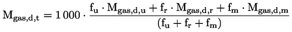
And for particle number:

Where fu, fr fm are respectively equal to 0,34, 0,33 and 0,33.
7. NUMERICAL EXAMPLES
7.1. Averaging window calculations
Table 1
Main calculation settings
|
|
610 |
|
Direction for averaging window calculation |
Forward |
|
Acquisition frequency [Hz] |
1 |
Figure 6 shows how averaging windows are defined on the basis of data recorded during an on-road test performed with PEMS. For sake of clarity, only the first 1 200 seconds of the trip are shown hereafter.
Seconds 0 up to 43 as well as seconds 81 to 86 are excluded due to operation under zero vehicle speed.
The first averaging window starts at t 1,1 = 0s and ends at second t 2,1 = 524 s (Table 3). The window average vehicle speed, integrated CO and NOx masses [g] emitted and corresponding to the valid data over the first averaging window are listed in Table 4.


Figure 6
Instantaneous CO2 emissions recorded during on-road test with PEMS as a function of time. Rectangular frames indicate the duration of the jth window. Data series named ‘Valid=100 / Invalid=0’ shows second by second data to be excluded from analysis

7.2. Evaluation of windows
Table 2
Calculation settings for the CO2 characteristic curve
|
CO2 Low Speed WLTC (P1) [g/km] |
154 |
|
CO2 High Speed WLTC (P2) [g/km] |
96 |
|
CO2 Extra-High Speed WLTC (P3) [g/km] |
120 |
|
Reference Point |
|
|
|
P 1 |
|
|
|
P 2 |
|
|
|
P 3 |
|
|
The definition of the CO2 characteristic curve is as follows:
For the section (P 1, P 2):
![]()
with

and: b1 = 154 – (– 1,543) × 19.0 = 154 + 29,317 = 183,317
For the section (P 2, P 3):
![]()
with
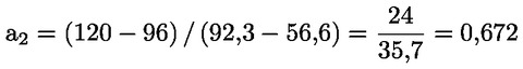
and: b2 = 96 – 0,672 × 56,6 = 96 – 38,035 = 57,965
Examples of calculation for the weighing factors and the window categorisation as urban, rural or motorway are:
For window #45:
![]()
![]()
For the characteristic curve:
![]()
Verification of:
![]()
![]()
124,498 × (1 – 25/100) ≤ 122,62 ≤ 124,498 × (1 + 25/100)
93,373 ≤ 122,62 ≤ 155,622
Leads to: w 45= 1
For window #556:
![]()
![]()
For the characteristic curve:
![]()
Verification of:
![]()
![]()
105,982 × (1 – 50/100) ≤ 72,15 ≤ 105,982 × (1 + 25/100)
52,991 ≤ 72,15 ≤ 79,487
Leads to:

w 556 = k 21 h 556 + k 22 = 0,04 · (– 31,922) + 2 = 0,723
with k 21 = 1/(tol 2 – tol 1) = 1/(50 – 25) = 0,04
and k 22 = k 21 = tol 2/(tol 2 – tol 1) = 50/(50 – 25) = 2
Table 3
Emissions numerical data
|
Window [#] |
t 1,j [s] |
t 2,j – Δt [s] |
t 2,j [s] |
[g] |
[g] |
|
1 |
0 |
523 |
524 |
609,06 |
610,22 |
|
2 |
1 |
523 |
524 |
609,06 |
610,22 |
|
… |
… |
|
… |
… |
… |
|
43 |
42 |
523 |
524 |
609,06 |
610,22 |
|
44 |
43 |
523 |
524 |
609,06 |
610,22 |
|
45 |
44 |
523 |
524 |
609,06 |
610,22 |
|
46 |
45 |
524 |
525 |
609,68 |
610,86 |
|
47 |
46 |
524 |
525 |
609,17 |
610,34 |
|
… |
… |
|
… |
… |
… |
|
100 |
99 |
563 |
564 |
609,69 |
612,74 |
|
… |
… |
|
… |
… |
… |
|
200 |
199 |
686 |
687 |
608,44 |
610,01 |
|
… |
… |
|
… |
… |
… |
|
474 |
473 |
1 024 |
1 025 |
609,84 |
610,60 |
|
475 |
474 |
1 029 |
1 030 |
609,80 |
610,49 |
|
|
… |
|
… |
… |
… |
|
556 |
555 |
1 173 |
1 174 |
609,96 |
610,59 |
|
557 |
556 |
1 174 |
1 175 |
609,09 |
610,08 |
|
558 |
557 |
1 176 |
1 177 |
609,09 |
610,59 |
|
559 |
558 |
1 180 |
1 181 |
609,79 |
611,23 |
Table 4
Window numerical data
|
Window [#] |
t1,j [s] |
t2,j [s] |
dj [km] |
[km/h] |
MCO2,j [g] |
MCO,j [g] |
MNOx,j [g] |
MCO2,d,j [g/km] |
MCO,d,j [g/km] |
MNOx,d,j [g/km] |
MCO2,d,cc( [g/km] |
Window (U/R/M) |
hj [%] |
wj [%] |
|
1 |
0 |
524 |
4,98 |
38,12 |
610,22 |
2,25 |
3,51 |
122,61 |
0,45 |
0,71 |
124,51 |
URBAN |
– 1,53 |
1,00 |
|
2 |
1 |
524 |
4,98 |
38,12 |
610,22 |
2,25 |
3,51 |
122,61 |
0,45 |
0,71 |
124,51 |
URBAN |
– 1,53 |
1,00 |
|
… |
… |
… |
… |
… |
… |
… |
… |
… |
… |
… |
… |
… |
… |
… |
|
43 |
42 |
524 |
4,98 |
38,12 |
610,22 |
2,25 |
3,51 |
122,61 |
0,45 |
0,71 |
124,51 |
URBAN |
– 1,53 |
1,00 |
|
44 |
43 |
524 |
4,98 |
38,12 |
610,22 |
2,25 |
3,51 |
122,61 |
0,45 |
0,71 |
124,51 |
URBAN |
– 1,53 |
1,00 |
|
45 |
44 |
524 |
4,98 |
38,12 |
610,22 |
2,25 |
3,51 |
122,62 |
0,45 |
0,71 |
124,51 |
URBAN |
– 1,51 |
1,00 |
|
46 |
45 |
525 |
4,99 |
38,25 |
610,86 |
2,25 |
3,52 |
122,36 |
0,45 |
0,71 |
124,30 |
URBAN |
– 1,57 |
1,00 |
|
… |
… |
… |
… |
… |
… |
… |
… |
… |
… |
… |
… |
… |
… |
… |
|
100 |
99 |
564 |
5,25 |
41,23 |
612,74 |
2,00 |
3,68 |
116,77 |
0,38 |
0,70 |
119,70 |
URBAN |
– 2,45 |
1,00 |
|
… |
… |
… |
… |
… |
… |
… |
… |
… |
… |
… |
… |
… |
… |
… |
|
200 |
199 |
687 |
6,17 |
46,32 |
610,01 |
2,07 |
4,32 |
98,93 |
0,34 |
0,70 |
111,85 |
RURAL |
– 11,55 |
1,00 |
|
… |
… |
… |
… |
… |
… |
… |
… |
… |
… |
… |
… |
… |
… |
… |
|
474 |
473 |
1 025 |
7,82 |
52,00 |
610,60 |
2,05 |
4,82 |
78,11 |
0,26 |
0,62 |
103,10 |
RURAL |
– 24,24 |
1,00 |
|
475 |
474 |
1 030 |
7,87 |
51,98 |
610,49 |
2,06 |
4,82 |
77,57 |
0,26 |
0,61 |
103,13 |
RURAL |
– 24,79 |
1,00 |
|
|
… |
… |
… |
… |
… |
… |
… |
… |
… |
… |
… |
… |
… |
… |
|
556 |
555 |
1 174 |
8,46 |
50,12 |
610,59 |
2,23 |
4,98 |
72,15 |
0,26 |
0,59 |
105,99 |
RURAL |
– 31,93 |
0,72 |
|
557 |
556 |
1 175 |
8,46 |
50,12 |
610,08 |
2,23 |
4,98 |
72,10 |
0,26 |
0,59 |
106,00 |
RURAL |
– 31,98 |
0,72 |
|
558 |
557 |
1 177 |
8,46 |
50,07 |
610,59 |
2,23 |
4,98 |
72,13 |
0,26 |
0,59 |
106,08 |
RURAL |
– 32,00 |
0,72 |
|
559 |
558 |
1 181 |
8,48 |
49,93 |
611,23 |
2,23 |
5,00 |
72,06 |
0,26 |
0,59 |
106,28 |
RURAL |
– 32,20 |
0,71 |
7.3. Urban, rural and motorway windows — Trip completeness
In this numerical example, the trip consists of 7 036 averaging windows. Table 5 lists the number of windows classified in urban, rural and motorway according to their average vehicle speed and divided in regions with respect to their distance to the CO2 characteristic curve. The trip is complete since it comprises at least 15 % of urban, rural and motorway windows out of the total number of windows. In addition the trip is characterised as normal since at least 50 % of the urban, rural and motorway windows are within the primary tolerances defined for the characteristic curve.
Table 5
Verification of trip completeness and normality
|
Driving Conditions |
Numbers |
Percentage of windows |
|
All Windows |
||
|
Urban |
1 909 |
1 909 /7 036 × 100 = 27,1 > 15 |
|
Rural |
2 011 |
2 011 /7 036 × 100 = 28,6 > 15 |
|
Motorway |
3 116 |
3 116 /7 036 × 100 = 44,3 > 15 |
|
Total |
1 909 + 2 011 + 3 116 = 7 036 |
|
|
Normal Windows |
||
|
Urban |
1 514 |
1 514 /1 909 × 100 = 79,3 > 50 |
|
Rural |
1 395 |
1 395 /2 011 × 100 = 69,4 > 50 |
|
Motorway |
2 708 |
2 708 /3 116 × 100 = 86,9 > 50 |
|
Total |
1 514 + 1 395 + 2 708 = 5 617 |
|
Appendix 6
Verification of trip dynamic conditions with method 2 (Power Binning)
1. INTRODUCTION
This Appendix describes the data evaluation according to the power binning method, named in this appendix ‘evaluation by normalisation to a standardised power frequency (SPF) distribution’.
2. SYMBOLS, PARAMETERS AND UNITS
|
ai |
Actual acceleration in time step i, if not other defined in an equation:
|
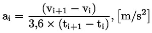
|
aref |
Reference acceleration for Pdrive, [0,45 m/s2] |
|
DWLTC |
intercept of the Veline from WLTC |
|
f0, f1, f2 |
Driving resistance coefficients |
|
i |
Time step for instantaneous measurements, minimum resolution 1Hz |
|
j |
Wheel power class, j = 1 to 9 |
|
kWLTC |
Slope of the Veline from WLTC |
|
mgas, i |
Instantaneous mass of the exhaust component ‘gas’ at time step i, [g/s] |
|
mgas, 3s, k |
3-second moving average mass flow of the exhaust gas component ‘gas’ in time step k given in 1 Hz resolution [g/s] |
|
|
Average emission value of an exhaust gas component in the wheel power class j, g/s |
|
Mgas,d |
Distance-specific emissions for the exhaust gas component ‘gas’ [g/km] |
|
p |
phase of WLTC (low, medium, high and extra-high), p = 1 – 4 |
|
Pdrag |
Engine drag power in the Veline approach where fuel injection is zero, [kW] |
|
Prated |
Maximum rated engine power as declared by the manufacturer, [kW] |
|
Prequired,i |
Power to overcome road load and inertia of a vehicle at time step i, [kW] |
|
Pr,,I |
Same as Prequired,i defined above used in longer equations |
|
Pwot(nnorm) |
Full load power curve, [kW] |
|
Pc,j |
Wheel power class limits for class number j, [kW] (Pc,j, lower bound represents the lower limit Pc,j, upper bound the upper limit) |
|
Pc,norm, j |
Wheel power class limits for class j as normalised power value, [-] |
|
Pr, I |
Power demand at the vehicle's wheel to overcome driving resistances in time step i [kW] |
|
Pw,3s,k |
3-second moving average power demand at the vehicle's wheel to overcome driving resistances in in time step k in 1 Hz resolution [kW] |
|
Pdrive |
Power demand at the wheel hub for a vehicle at reference speed and acceleration [kW] |
|
Pnorm |
Normalised power demand at the wheel hub [-] |
|
ti |
Total time in step i, [s] |
|
tc,j |
Time share of the wheel power class j, [%] |
|
ts |
Start time of the WLTC phase p, [s] |
|
te |
End time of the WLTC phase p, [s] |
|
TM |
Test mass of the vehicle, [kg]; to be specified per section: real test weight in PEMS test, NEDC inertia class weight or WLTP masses (TML, TMH or TMind) |
|
SPF |
Standardised Power Frequency distribution |
|
vi |
Actual vehicle speed in time step i, [km/h] |
|
|
Average vehicle speed in the wheel power class j, km/h |
|
vref |
Reference velocity for Pdrive, [70 km/h] |
|
v3s,k |
3-second moving average of the vehicle velocity in time step k, [km/h]. |
3. EVALUATION OF THE MEASURED EMISSIONS USING A STANDARDISED WHEEL POWER FREQUENCY DISTRIBUTION
The power binning method uses the instantaneous emissions of the pollutants, mgas, i (g/s) calculated in accordance with Appendix 4.
The mgas, i values shall be classified in accordance with the corresponding power at the wheels and the classified average emissions per power class shall be weighted to obtain the emission values for a test with a normal power distribution according to the following points.
3.1. Sources for the actual wheel power
The actual wheel power Pr,i shall be the total power to overcome air resistance, rolling resistance, longitudinal inertia of the vehicle and rotational inertia of the wheels.
When measured and recorded, the wheel power signal shall use a torque signal meeting the linearity requirements laid down in Appendix 2, point 3.2.
As an alternative, the actual wheel power may be determined from the instantaneous CO2 emissions following the procedure laid down in point 4 of this Appendix.
3.2. Classification of the moving averages to urban, rural and motorway
The standard power frequencies are defined for urban driving and for the total trip (see paragraph 3.4) and a separate evaluation of the emissions shall be made for the total trip and for the urban part. The three-second moving averages calculated according to paragraph 3.3 shall therefore be allocated later to urban and extra-urban driving conditions according to the velocity signal (v3s,k) as outlined in Table 1-1.
Table 1-1
Speed ranges for the allocation of test data to urban, rural and motorway conditions in the power binning method
|
|
Urban |
Rural (1) |
Motorway (1) |
|
v3s,k [km/h] |
0 to ≤ 60 |
> 60 to ≤ 90 |
> 90 |
|
(1) For the evaluation the three-second moving averages need only to be classified later into events under urban velocity conditions for the ‘urban’ part of the trip. For the ‘total’ trip all three-second moving averages shall be used independently from the velocity. |
|||
Where
|
v3s,k |
3-second moving average of the vehicle velocity in time step k, [km/h] |
|
k |
time step for moving average values. |
3.3. Calculation of the moving averages of the instantaneous test data
Three-second moving averages shall be calculated from all relevant instantaneous test data to reduce influences of possibly imperfect time alignment between emission mass flow and wheel power. The moving average values shall be computed in a 1 Hz frequency:


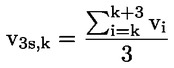
Where
|
k |
time step for moving average values |
|
i |
time step from instantaneous test data. |
3.4. Set up of the wheel power classes for emission classification
|
3.4.1. |
The power classes and the corresponding time shares of the power classes in normal driving are defined for normalised power values to be representative for any LDV (Table 1-2).
Table 1-2 Normalised standard power frequencies for urban driving and for a weighted average for a total trip consisting of 1/3 urban, 1/3 road, 1/3 motorway mileage
The Pc,norm columns in Table 1-2 shall be de-normalised by multiplication with Pdrive, where Pdrive is the actual wheel power of the tested car in the type approval settings at the chassis dynamometer at vref and aref. Pc,j [kW] = Pc,norm, j × Pdrive
Where: — j is the power class index according to Table 1-2 — The driving resistance coefficients f0, f1, f2 should be calculated with a least squares regression analysis from the following definition: — PCorrected/v = f0 + f1 × v + f2 × v2 — with (PCorrected/v) being the road load force at vehicle velocity v for the NEDC test cycle defined in point 5.1.1.2.8 of Appendix 7 to Annex 4a of UNECE Regulation 83 — 07 series of amendments. — TMNEDC is the inertia class of the vehicle in the type approval test, [kg]. |
||||||||||||||||||||||||||||||||||||||||||||||||||||||

|
3.4.2. |
Correction of the wheel power classes
The maximum wheel power class to be considered is the highest class in Table 1-2 which includes (Prated × 0,9). The time shares of all excluded classes shall be added to the highest remaining class. From each Pc,norm,j the corresponding Pc,j shall be calculated to define the upper and lower bounds in kW per wheel power class for the tested vehicle as shown in Figure 1. 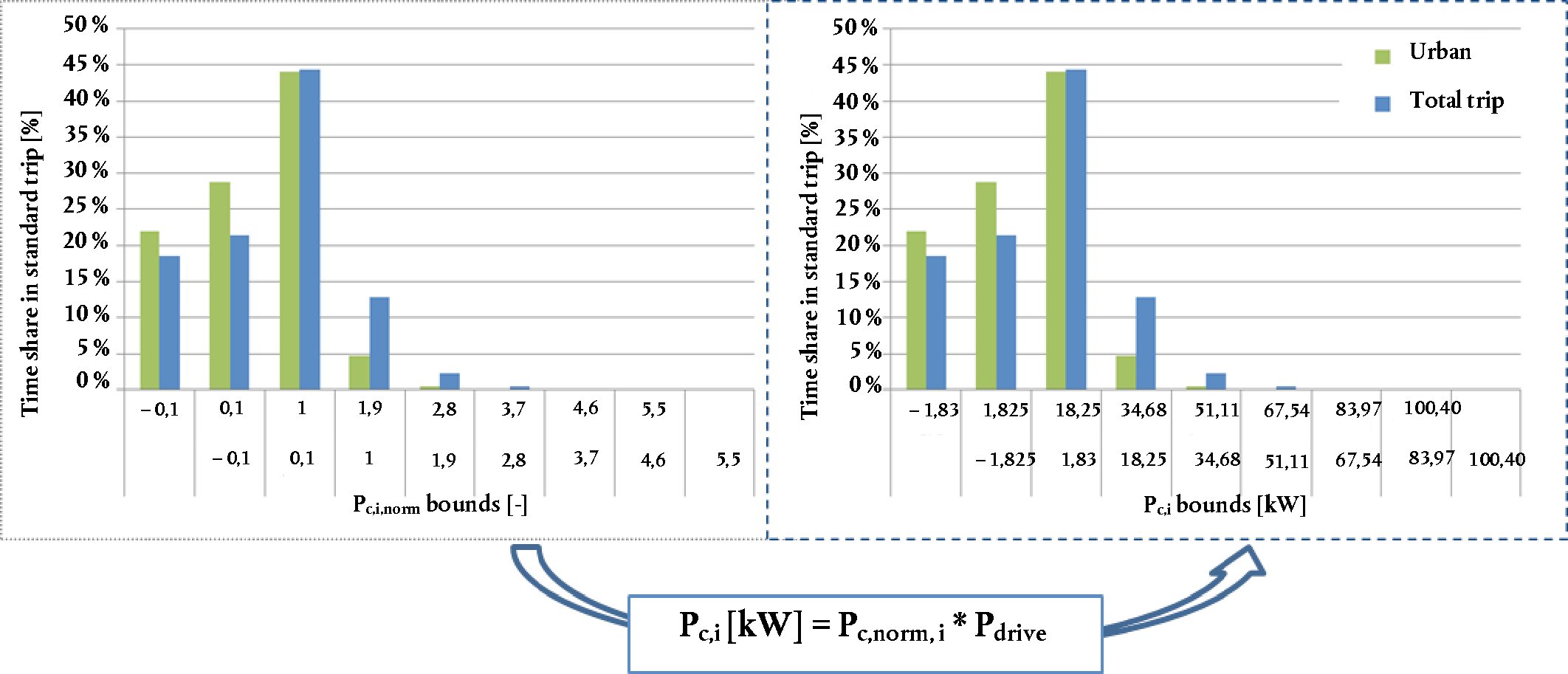
An example for this de-normalisation is given below. Example for input data:
Corresponding results: Pdrive = 70 [km/h]/3,6 × (79,19 + 0,73 [N/(km/h)] × 70[km/h] + 0,03 [N/(km/h)2] × (70 [km/h])2 + 1 470 [kg] × 0,45[m/s2]) × 0,001 Pdrive = 18.25 kW
Table 2 De-normalised standard power frequency values from Table 1-2 (for Example 1)
Table 3 De-normalised standard power frequency values from Table 1-2 ( for Example 2)
|
||||||||||||||||||||||||||||||||||||||||||||||||||||||||||||||||||||||||||||||||||||||||||||||||||||||||||||||||||||||||||||||||||||
3.5. Classification of the moving average values
Each moving average value calculated according to point 3.2 shall be sorted into the de-normalised wheel power class into which the actual 3-second moving average wheel power Pw,3s,k fits. The de-normalised wheel power class limits have to be calculated according to point 3.3.
The classification shall be done for all three-second moving averages of the entire valid trip data as well as for the all urban trip parts. Additionally all moving averages classified to urban according to the velocity limits defined in Table 1-1 shall be classified into one set of urban power classes independently of the time when the moving average appeared in the trip.
Then the average of all three-second moving average values within a wheel power class shall be calculated for each wheel power class per parameter. The equations are described below and shall be applied once for the urban data set and once for the total data set.
Classification of the 3-second moving average values into power class j (j = 1 to 9):
if
![]()
then: class index for emissions and velocity = j.
The number of 3-second moving average values shall be counted for each power class:
if
![]()
then: countsj = n + 1 (countsj is counting the number of 3-second moving average emission value in a power class to check later the minimum coverage demands).
3.6. Check of power class coverage and of normality of power distribution
For a valid test the time shares of the single wheel power classes shall be in the ranges listed in Table 4.
Table 4
Minimum and maximum shares per power class for a valid test
|
|
Pc,norm,j [-] |
Total trip |
Urban trip parts |
|||
|
Power class No |
From > |
to ≤ |
lower bound |
upper bound |
lower bound |
upper bound |
|
Sum 1 + 2 (1) |
|
0,1 |
15 % |
60 % |
5 % (1) |
60 % |
|
3 |
0,1 |
1 |
35 % |
50 % |
28 % |
50 % |
|
4 |
1 |
1,9 |
7 % |
25 % |
0,7 % |
25 % |
|
5 |
1,9 |
2,8 |
1,0 % |
10 % |
> 5 counts |
5 % |
|
6 |
2,8 |
3,7 |
> 5 counts |
2,5 % |
0 % |
2 % |
|
7 |
3,7 |
4,6 |
0 % |
1,0 % |
0 % |
1 % |
|
8 |
4,6 |
5,5 |
0 % |
0,5 % |
0 % |
0,5 % |
|
9 |
5,5 |
|
0 % |
0,25 % |
0 % |
0,25 % |
|
(1) Representing the total of motoring and low power conditions |
||||||
In addition to the requirements in Table 4, a minimum coverage of 5 counts is demanded for the total trip in each wheel power class up to the class containing 90 % of the rated power to provide a sufficient sample size.
A minimum coverage of five counts is required for the urban part of the trip in each wheel power class up to class No 5. If the counts in the urban part of the trip in a wheel power class above No 5 are less than five, the average class emission value shall be set to zero.
3.7. Averaging of the measured values per wheel power class
The moving averages sorted in each wheel power class shall be averaged as follows:


Where
|
j |
wheel power class 1 to 9 according to Table 1 |
|
|
average emission value of an exhaust gas component in a wheel power class (separate value for total trip data and for the urban parts of the trip), [g/s] |
|
|
average velocity in a wheel power class (separate value for total trip data and for the urban parts of the trip), [km/h] |
|
k |
time step for moving average values. |
3.8. Weighting of the average values per wheel power class
The average values of each wheel power class shall be multiplied with the time share, tC,j per class according to Table 1-2 and summed up to produce the weighted average value for each parameter. This value represents the weighted result for a trip with the standardised power frequencies. The weighted averages shall be computed for the urban part of the test data using the time shares for urban power distribution as well as for the total trip using the time shares for the total.
The equations are described below and shall be applied once for the urban data set and once for the total data set.

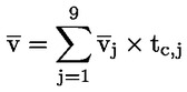
3.9. Calculation of the weighted distance-specific emission value
The time-based weighted averages of the emissions in the test shall be converted into distance-based emissions once for the urban data set and once for the total data set as follows:

Using this formula, weighted averages shall be calculated for the following pollutants:
|
Mw,NOx,d |
weighted NOx test result in [mg/km] |
|
Mw,CO,d |
weighted CO test result in [mg/km] |
4. ASSESSMENT OF THE WHEEL POWER FROM THE INSTANTANEOUS CO2 MASS FLOW
The power at the wheels (Pw,i) can be computed from the measured CO2 mass flow in 1 Hz basis. For this calculation the vehicle-specific CO2 lines (‘Veline’) shall be used.
The Veline shall be calculated from the vehicle type approval test in the WLTC according to the test procedure described in UNECE Global Technical Regulation No 15 — worldwide harmonised light vehicles test procedure (ECE/TRANS/180/Add.15).
The average wheel power per WLTC phase shall be calculated. in 1 Hz from the driven velocity and from the chassis dynamometer settings. All wheel power values below the drag power shall be set to the drag power value.

With
|
f0, f1, f2 |
road load coefficients used in in the WLTP test performed with the vehicle |
|
TM |
test mass of the vehicle in the WLTP test performed with the vehicle in [kg] |
P drag = – 0,04 × P rated
if Pw,i < Pdrag then Pw,i = Pdrag
The average power per WLTC phase is calculated from the 1 Hz wheel power according to:
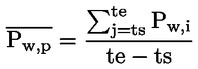
With
|
p |
phase of WLTC (low, medium, high and extra-high) |
|
ts |
Start time of the WLTC phase p, [s] |
|
te |
end time of the WLTC phase p, [s]. |
Then a linear regression shall be made with the CO2 mass flow from the bag values of the WLTC on the y-axis and from the average wheel power Pw,p per phase on the x-axis as illustrated in Figure 2.
The resulting Veline equation defines the CO2 mass flow as function of the wheel power:
|
|
CO2 in [g/h] |
Where
|
kWLTC |
slope of the Veline from WLTC, [g/kWh] |
|
DWLTC |
intercept of the Veline from WLTC, [g/h]. |
Figure 2
Schematic picture of setting up the vehicle-specific Veline from the CO2 test results in the four phases of the WLTC

The actual wheel power shall be calculated from the measured CO2 mass flow according to:

With
CO2 in [g/h]
PW,j in [kW]
The above equation can be used to provide PWi for the classification of the measured emissions as described in point 3 with following additional conditions in the calculation
|
if vi < 0,5 and if ai < 0 then P w,i = 0 |
v in [m/s] |
|
if CO2i < 0,5 X DWLTC then P w,i = Pdrag |
v in [m/s]. |
Appendix 7
Selection of vehicles for PEMS testing at initial type approval
1. INTRODUCTION
Due to their particular characteristics, PEMS tests are not required to be performed for each ‘vehicle type with regard to emissions and vehicle repair and maintenance information’ as defined in Article 2(1) of this Regulation, which is called in the following ‘vehicle emission type’. Several vehicle emission types may be put together by the vehicle manufacturer to form a ‘PEMS test family’ according to the requirements of point 3, which shall be validated according to the requirements of point 4.
2. SYMBOLS, PARAMETERS AND UNITS
|
N |
— |
Number of vehicle emission types |
|
NT |
— |
Minimum number of vehicle emission types |
|
PMRH |
— |
highest power-to-mass-ratio of all vehicles in the PEMS test family |
|
PMRL |
— |
lowest power-to-mass-ratio of all vehicles in the PEMS test family |
|
V_eng_max |
— |
maximum engine volume of all vehicles within the PEMS test family. |
3. PEMS TEST FAMILY BUILDING
A PEMS test family shall comprise vehicles with similar emission characteristics. Upon the choice of the manufacturer vehicle emission types may be included in a PEMS test family only if they are identical with respect to the characteristics in points 3.1 and 3.2.
3.1. Administrative criteria
|
3.1.1. |
The approval authority issuing the emission type approval according to Regulation (EC) 715/2007. |
|
3.1.2. |
A single vehicle manufacturer. |
3.2. Technical criteria
|
3.2.1. |
Propulsion type (e.g. ICE, HEV, PHEV). |
|
3.2.2. |
Type(s) of fuel(s) (e.g. petrol, diesel, LPG, NG, …). Bi- or flex-fuelled vehicles may be grouped with other vehicles, with which they have one of the fuels in common. |
|
3.2.3. |
Combustion process (e.g. two stroke, four stroke) |
|
3.2.4. |
Number of cylinders |
|
3.2.5. |
Configuration of the cylinder block (e.g. in-line, V, radial, horizontally opposed) |
|
3.2.6. |
Engine volume The vehicle manufacturer shall specify a value V_eng_max (= maximum engine volume of all vehicles within the PEMS test family). The engine volumes of vehicles in the PEMS test family shall not deviate more than – 22 % from V_eng_max if V_eng_max ≥ 1 500 ccm and – 32 % from V_eng_max if V_eng_max < 1 500 ccm. |
|
3.2.7. |
Method of engine fuelling (e.g. indirect or direct or combined injection) |
|
3.2.8. |
Type of cooling system (e.g. air, water, oil) |
|
3.2.9. |
Method of aspiration such as naturally aspirated, pressure charged, type of pressure charger (e.g. externally driven, single or multiple turbo, variable geometries, …) |
|
3.2.10. |
Types and sequence of exhaust after-treatment components (e.g. three-way catalyst, oxidation catalyst, lean NOx trap, SCR, lean NOx catalyst, particulate trap). |
|
3.2.11. |
Exhaust gas recirculation (with or without, internal/external, cooled/non-cooled, low/high pressure). |
3.3. Extension of a PEMS test family
An existing PEMS test family may be extended by adding new vehicle emission types to it. The extended PEMS test family and its validation must also fulfil the requirements of points 3 and 4. This may in particular require the PEMS testing of additional vehicles to validate the extended PEMS test family according to point 4.
3.4. Alternative PEMS test family
As an alternative to the provisions of points 3.1 to 3.2 the vehicle manufacturer may define a PEMS test family, which is identical to a single vehicle emission type. In this the requirement of point 4.1.2 for validating the PEMS test family shall not apply.
4. VALIDATION OF A PEMS TEST FAMILY
4.1. General requirements for validating a PEMS test family
|
4.1.1. |
The vehicle manufacturer presents a representative vehicle of the PEMS test family to the type-approval authority. The vehicle shall be subject to a PEMS test carried out by a Technical Service to demonstrate compliance of the representative vehicle with the requirements of this Annex. |
|
4.1.2. |
The authority responsible for issuing the emission type-approval in accordance with Regulation (EC) No 715/2007 selects additional vehicles according to the requirements of point 4.2 of this Appendix for PEMS testing carried out by a Technical Service to demonstrate compliance of the selected vehicles with the requirements of this Annex. The technical criteria for selection of an additional vehicle according to point 4.2 of this Appendix shall be recorded with the test results. |
|
4.1.3. |
With agreement of the type-approval authority, a PEMS test can also be driven by a different operator witnessed by a Technical Service, provided that at least the tests of the vehicles required by of this Appendix and in total at least 50 % of the PEMS tests required by this Appendix for validating the PEMS test family are driven by a Technical Service. In such case the Technical Service remains responsible for the proper execution of all PEMS tests pursuant to the requirements of this Annex. |
|
4.1.4. |
A PEMS test results of a specific vehicle may be used for validating different PEMS test families according to the requirements of this Appendix under the following conditions: — the vehicles included in all PEMS test families to be validated are approved by a single authority according to the requirements of Regulation (EC) 715/2007 and this authority agrees to the use of the specific vehicle's PEMS test results for validating different PEMS test families, — each PEMS test family to be validated includes a vehicle emission type, which comprises the specific vehicle; For each validation the applicable responsibilities are considered to be borne by the manufacturer of the vehicles in the respective family, regardless of whether this manufacturer was involved in the PEMS test of the specific vehicle emission type. |
4.2. Selection of vehicles for PEMS testing when validating a PEMS test family
By selecting vehicles from a PEMS test family it should be ensured that the following technical characteristics relevant for pollutant emissions are covered by a PEMS test. One vehicle selected for testing can be representative for different technical characteristics. For the validation of a PEMS test family vehicles shall be selected for PEMS testing as follows:
|
4.2.1. |
For each combination of fuels (e.g. petrol-LPG, petrol-NG, petrol only), on which some vehicle of the PEMS test family can operate, at least one vehicle that can operate on this combination of fuels shall be selected for PEMS testing. |
|
4.2.2. |
The manufacturer shall specify a value PMRH (= highest power-to-mass-ratio of all vehicles in the PEMS test family) and a value PMRL (= lowest power-to-mass-ratio of all vehicles in the PEMS test family). Here the ‘power-to-mass-ratio’ corresponds to the ratio of the maximum net power of the internal combustion engine as indicated in point 3.2.1.8 of Appendix 3 to Annex I of this Regulation and of the reference mass as defined in Article 3(3) of Regulation (EC) No 715/2007. At least one vehicle configuration representative for the specified PMRH and one vehicle configuration representative for the specified PMRL of a PEMS test family shall be selected for testing. If the power-to-mass ratio of a vehicle deviates by not more than 5 % from the specified value for PMRH, or PMRL, the vehicle should be considered as representative for this value. |
|
4.2.3. |
At least one vehicle for each transmission type (e.g. manual, automatic, DCT) installed in vehicles of the PEMS test family shall be selected for testing. |
|
4.2.4. |
At least one four-wheel drive vehicle (4 × 4 vehicle) shall be selected for testing if such vehicles are part of the PEMS test family. |
|
4.2.5. |
For each engine volume occurring on a vehicle in the PEMS family at least one representative vehicle shall be tested. |
|
4.2.6. |
At least one vehicle for each number of installed exhaust after-treatment components shall be selected for testing. |
|
4.2.7. |
Notwithstanding the provisions in points 4.2.1 to 4.2.6, at least the following number of vehicle emission types of a given PEMS test family shall be selected for testing:
|
5. REPORTING
|
5.1. |
The vehicle manufacturer provides a full description of the PEMS test family, which includes in particular the technical criteria described in point 3.2 and submits it to the responsible type approval authority. |
|
5.2. |
The manufacturer attributes a unique identification number of the format MS-OEM-X-Y to the PEMS test family and communicates it to the type approval authority. Here MS is the distinguishing number of the Member State issuing the EC type-approval ( 56 ), OEM is the 3 character manufacturer, X is a sequential number identifying the original PEMS test family and Y is a counter for its extensions (starting with 0 for a PEMS test family not extended yet). |
|
5.3. |
The type approval authority and the vehicle manufacturer shall maintain a list of vehicle emission types being part of a given PEMS test family on the basis of emission type approval numbers. For each emission type all corresponding combinations of vehicle type approval numbers, types, variants and versions as defined in Sections 0.10 and 0.2 of the vehicle's EC certificate of conformity shall be provided as well. |
|
5.4. |
The type approval authority and the vehicle manufacturer shall maintain a list of vehicle emission types selected for PEMS testing in order validate a PEMS test family in accordance with point 4, which also provides the necessary information on how the selection criteria of point 4.2 are covered. This list shall also indicate whether the provisions of point 4.1.3 were applied for a particular PEMS test. |
Appendix 8
Data exchange and reporting requirements
1. INTRODUCTION
This Appendix describes the requirements for the data exchange between the measurement systems and the data evaluation software and for the reporting and exchange of intermediate and final results after the completion of the data evaluation.
The exchange and reporting of mandatory and optional parameters shall follow the requirements of point 3.2 of Appendix 1. The data specified in the exchange and reporting files of point 3 shall be reported to ensure a complete traceability of final results.
2. SYMBOLS, PARAMETERS AND UNITS
|
a 1 |
— |
coefficient of the CO2 characteristic curve |
|
b 1 |
— |
coefficient of the CO2 characteristic curve |
|
a 2 |
— |
coefficient of the CO2 characteristic curve |
|
b 2 |
— |
coefficient of the CO2 characteristic curve |
|
k 11 |
— |
coefficient of the weighing function |
|
k 12 |
— |
coefficient of the weighing function |
|
k 21 |
— |
coefficient of the weighing function |
|
k 22 |
— |
coefficient of the weighing function |
|
tol 1 |
— |
primary tolerance |
|
tol 2 |
— |
secondary tolerance. |
3. DATA EXCHANGE AND REPORTING FORMAT
3.1. General
Emission values as well as any other relevant parameters shall be reported and exchanged as csv-formatted data file. Parameter values shall be separated by a comma, ASCII-Code #h2C. The decimal marker of numerical values shall be a point, ASCII-Code #h2E. Lines shall be terminated by carriage return, ASCII-Code #h0D. No thousands separators shall be used.
3.2. Data exchange
Data shall be exchanged between the measurement systems and the data evaluation software by means of a standardised reporting file that contains a minimum set of mandatory and optional parameters. The data exchange file shall be structured as follows: The first 195 lines shall be reserved for a header that provides specific information about, e.g. the test conditions, the identity and calibration of the PEMS equipment (Table 1). Lines 198-200 shall contain the labels and units of parameters. Lines 201 and all consecutive data lines shall comprise the body of the data exchange file and report parameter values (Table 2). The body of the data exchange file shall contain at least as many data lines as the test duration in seconds multiplied by the recording frequency in Hertz.
3.3. Intermediate and final results
Manufacturers shall record summary parameters of intermediate results as structured in Table 3. The information in Table 3 shall be obtained prior to the application of the data evaluation methods laid down in Appendices 5 and 6.
The vehicle manufacturer shall record the results of the two data evaluation methods in separate files. The results of the data evaluation with the method described in Appendix 5 shall be reported according to Tables 4, 5 and 6. The results of the data evaluation with the method described in Appendix 6 shall be reported according to Tables 7, 8 and 9. The header of the data reporting file shall be composed of three parts. The first 95 lines shall be reserved for specific information about the settings of the data evaluation method. Lines 101-195 shall report the results of the data evaluation method. Lines 201-490 shall be reserved for reporting the final emission results. Line 501 and all consecutive data lines comprise the body of the data reporting file and shall contain the detailed results of the data evaluation.
4. TECHNICAL REPORTING TABLES
4.1. Data exchange
Table 1
Header of the data exchange file
|
Line |
Parameter |
Description/unit |
|
1 |
TEST ID |
[code] |
|
2 |
Test date |
[day.month.year] |
|
3 |
Organisation supervising the test |
[name of the organisation] |
|
4 |
Test location |
[city, country] |
|
5 |
Person supervising the test |
[name of the principal supervisor] |
|
6 |
Vehicle driver |
[name of the driver] |
|
7 |
Vehicle type |
[vehicle name] |
|
8 |
Vehicle manufacturer |
[name] |
|
9 |
Vehicle model year |
[year] |
|
10 |
Vehicle ID |
[VIN code] |
|
11 |
Odometer value at test start |
[km] |
|
12 |
Odometer value at test end |
[km] |
|
13 |
Vehicle category |
[category] |
|
14 |
Type approval emissions limit |
[Euro X] |
|
15 |
Engine type |
[e.g. spark ignition, compression ignition] |
|
16 |
Engine rated power |
[kW] |
|
17 |
Peak torque |
[Nm] |
|
18 |
Engine displacement |
[ccm] |
|
19 |
Transmission |
[e.g. manual, automatic] |
|
20 |
Number of forward gears |
[#] |
|
21 |
Fuel |
[e.g. gasoline, diesel] |
|
22 |
Lubricant |
[product label] |
|
23 |
Tyre size |
[width/height/rim diameter] |
|
24 |
Front and rear axle tire pressure |
[bar; bar] |
|
25 |
Road load parameters |
[F0, F1, F2] |
|
26 |
Type-approval test cycle |
[NEDC, WLTC] |
|
27 |
Type-approval CO2 emissions |
[g/km] |
|
28 |
CO2 emissions in WLTC mode Low |
[g/km] |
|
29 |
CO2 emissions in WLTC mode Mid |
[g/km] |
|
30 |
CO2 emissions in WLTC mode High |
[g/km] |
|
31 |
CO2 emissions in WLTC mode Extra High |
[g/km] |
|
32 |
Vehicle test mass (1) |
[kg; % (2)] |
|
33 |
PEMS manufacturer |
[name] |
|
34 |
PEMS type |
[PEMS name] |
|
35 |
PEMS serial number |
[number] |
|
36 |
PEMS power supply |
[e.g. % battery type] |
|
37 |
Gas analyser manufacturer |
[name] |
|
38 |
Gas analyser type |
[type] |
|
39 |
Gas analyser serial number |
[number] |
|
40-50 (3) |
… |
… |
|
51 |
EFM manufacturer (4) |
[name] |
|
52 |
EFM sensor type (4) |
[functional principle] |
|
53 |
EFM serial number (4) |
[number] |
|
54 |
Source of exhaust mass flow rate |
[EFM/ECU/sensor] |
|
55 |
Air pressure sensor |
[type, manufacturer] |
|
56 |
Test date |
[day.month.year] |
|
57 |
Start time of pre-test procedure |
[h:min] |
|
58 |
Start time of trip |
[h:min] |
|
59 |
Start time of post-test procedure |
[h:min] |
|
60 |
End time of pre-test procedure |
[h:min] |
|
61 |
End time of trip |
[h:min] |
|
62 |
End time of post-test procedure |
[h:min] |
|
63-70 (5) |
… |
… |
|
71 |
Time correction: Shift THC |
[s] |
|
72 |
Time correction: Shift CH4 |
[s] |
|
73 |
Time correction: Shift NMHC |
[s] |
|
74 |
Time correction: Shift O2 |
[s] |
|
75 |
Time correction: Shift PN |
[s] |
|
76 |
Time correction: Shift CO |
[s] |
|
77 |
Time correction: Shift CO2 |
[s] |
|
78 |
Time correction: Shift NO |
[s] |
|
79 |
Time correction: Shift NO2 |
[s] |
|
80 |
Time correction: Shift exhaust mass flow rate |
[s] |
|
81 |
Span reference value THC |
[ppm] |
|
82 |
Span reference value CH4 |
[ppm] |
|
83 |
Span reference value NMHC |
[ppm] |
|
84 |
Span reference value O2 |
[%] |
|
85 |
Span reference value PN |
[#] |
|
86 |
Span reference value CO |
[ppm] |
|
87 |
Span reference value CO2 |
[%] |
|
88 |
Span reference value NO |
[ppm] |
|
89 |
Span Reference Value NO2 |
[ppm] |
|
90-95 (5) |
… |
… |
|
96 |
Pre-test zero response THC |
[ppm] |
|
97 |
Pre-test zero response CH4 |
[ppm] |
|
98 |
Pre-test zero response NMHC |
[ppm] |
|
99 |
Pre-test zero response O2 |
[%] |
|
100 |
Pre-test zero response PN |
[#] |
|
101 |
Pre-test zero response CO |
[ppm] |
|
102 |
Pre-test zero response CO2 |
[%] |
|
103 |
Pre-test zero response NO |
[ppm] |
|
104 |
Pre-test zero response NO2 |
[ppm] |
|
105 |
Pre-test span response THC |
[ppm] |
|
106 |
Pre-test span response CH4 |
[ppm] |
|
107 |
Pre-test span response NMHC |
[ppm] |
|
108 |
Pre-test span response O2 |
[%] |
|
109 |
Pre-test span response PN |
[#] |
|
110 |
Pre-test span response CO |
[ppm] |
|
111 |
Pre-test span response CO2 |
[%] |
|
112 |
Pre-test span response NO |
[ppm] |
|
113 |
Pre-test span response NO2 |
[ppm] |
|
114 |
Post-test zero response THC |
[ppm] |
|
115 |
Post-test zero response CH4 |
[ppm] |
|
116 |
Post-test zero response NMHC |
[ppm] |
|
117 |
Post-test zero response O2 |
[%] |
|
118 |
Post-test zero response PN |
[#] |
|
119 |
Post-test zero response CO |
[ppm] |
|
120 |
Post-test zero response CO2 |
[%] |
|
121 |
Post-test zero response NO |
[ppm] |
|
122 |
Post-test zero response NO2 |
[ppm] |
|
123 |
Post-test span response THC |
[ppm] |
|
124 |
Post-test span response CH4 |
[ppm] |
|
125 |
Post-test span response NMHC |
[ppm] |
|
126 |
Post-test span response O2 |
[%] |
|
127 |
Post-test span response PN |
[#] |
|
128 |
Post-test span response CO |
[ppm] |
|
129 |
Post-test span response CO2 |
[%] |
|
130 |
Post-test span response NO |
[ppm] |
|
131 |
Post-test span response NO2 |
[ppm] |
|
132 |
PEMS validation — results THC |
[mg/km;%] (6) |
|
133 |
PEMS validation — results CH4 |
[mg/km;%] (6) |
|
134 |
PEMS validation — results NMHC |
[mg/km;%] (6) |
|
135 |
PEMS validation — results PN |
[#/km;%] (6) |
|
136 |
PEMS validation — results CO |
[mg/km;%] (6) |
|
137 |
PEMS validation — results CO2 |
[g/km;%] (6) |
|
138 |
PEMS validation — results NOX |
[mg/km;%] (6) |
|
… (7) |
… (7) |
… (7) |
|
(1) Mass of the vehicle as tested on the road, including the mass of the driver and all PEMS components. (2) Percentage shall indicate the deviation from the gross vehicle weight. (3) Placeholders for additional information about analyser manufacturer and serial number in case multiple analysers are used. Number of reserved rows is indicative only; no empty rows shall occur in the completed data reporting file. (4) Mandatory if the exhaust mass flow rate is determined by an EFM. (5) If required, additional information may be added here. (6) PEMS validation is optional; distance-specific emissions as measured with the PEMS; Percentage shall indicate the deviation from the laboratory reference. (7) Additional parameters may be added until line 195 to characterise and label the test. |
||
Table 2
Body of the data exchange file; the rows and columns of this table shall be transposed in the body of the data exchange file
|
Line |
198 |
199 (1) |
200 |
201 |
|
|
Time |
trip |
[s] |
|
|
|
Vehicle speed (3) |
Sensor |
[km/h] |
|
|
|
Vehicle speed (3) |
GPS |
[km/h] |
|
|
|
Vehicle speed (3) |
ECU |
[km/h] |
|
|
|
Latitude |
GPS |
[deg:min:s] |
|
|
|
Longitude |
GPS |
[deg:min:s] |
|
|
|
Altitude (3) |
GPS |
[m] |
|
|
|
Altitude (3) |
Sensor |
[m] |
|
|
|
Ambient pressure |
Sensor |
[kPa] |
|
|
|
Ambient temperature |
Sensor |
[K] |
|
|
|
Ambient humidity |
Sensor |
[g/kg; %] |
|
|
|
THC concentration |
Analyser |
[ppm] |
|
|
|
CH4 concentration |
Analyser |
[ppm] |
|
|
|
NMHC concentration |
Analyser |
[ppm] |
|
|
|
CO concentration |
Analyser |
[ppm] |
|
|
|
CO2 concentration |
Analyser |
[ppm] |
|
|
|
NOX concentration |
Analyser |
[ppm] |
|
|
|
NO concentration |
Analyser |
[ppm] |
|
|
|
NO2 concentration |
Analyser |
[ppm] |
|
|
|
O2 concentration |
Analyser |
[ppm] |
|
|
|
PN concentration |
Analyser |
[#/m3] |
|
|
|
Exhaust mass flow rate |
EFM |
[kg/s] |
|
|
|
Exhaust temperature in the EFM |
EFM |
[K] |
|
|
|
Exhaust mass flow rate |
Sensor |
[kg/s] |
|
|
|
Exhaust mass flow rate |
ECU |
[kg/s] |
|
|
|
THC mass |
Analyser |
[g/s] |
|
|
|
CH4 mass |
Analyser |
[g/s] |
|
|
|
NMHC mass |
Analyser |
[g/s] |
|
|
|
CO mass |
Analyser |
[g/s] |
|
|
|
CO2 mass |
Analyser |
[g/s] |
|
|
|
NOX mass |
Analyser |
[g/s] |
|
|
|
NO mass |
Analyser |
[g/s] |
|
|
|
NO2 mass |
Analyser |
[g/s] |
|
|
|
O2 mass |
Analyser |
[g/s] |
|
|
|
PN |
Analyser |
[#/s] |
|
|
|
Gas measurement active |
PEMS |
[active (1); inactive (0); error (>1)] |
|
|
|
Engine speed |
ECU |
[rpm] |
|
|
|
Engine torque |
ECU |
[Nm] |
|
|
|
Torque at driven axle |
Sensor |
[Nm] |
|
|
|
Wheel rotational speed |
Sensor |
[rad/s] |
|
|
|
Fuel rate |
ECU |
[g/s] |
|
|
|
Engine fuel flow |
ECU |
[g/s] |
|
|
|
Engine intake air flow |
ECU |
[g/s] |
|
|
|
Coolant temperature |
ECU |
[K] |
|
|
|
Oil temperature |
ECU |
[K] |
|
|
|
Regeneration status |
ECU |
— |
|
|
|
Pedal position |
ECU |
[%] |
|
|
|
Vehicle status |
ECU |
[error (1); normal (0)] |
|
|
|
Per cent torque |
ECU |
[%] |
|
|
|
Per cent friction torque |
ECU |
[%] |
|
|
|
State of charge |
ECU |
[%] |
|
|
|
… (4) |
… (4) |
… (4) |
|
|
(1) This column can be omitted if the parameter source is part of the label in column 198. (2) Actual values to be included from line 201 onward until the end of data (3) To be determined by at least one method (4) Additional parameters may be added to characterise vehicle and test conditions. |
||||
4.2. Intermediate and final results
4.2.1. Intermediate results
Table 3
Reporting file #1 — Summary parameters of intermediate results
|
Line |
Parameter |
Description/unit |
|
1 |
Total trip distance |
[km] |
|
2 |
Total trip duration |
[h:min:s] |
|
3 |
Total stop time |
[min:s] |
|
4 |
Trip average speed |
[km/h] |
|
5 |
Trip maximum speed |
[km/h] |
|
6 |
Average THC concentration |
[ppm] |
|
7 |
Average CH4 concentration |
[ppm] |
|
8 |
Average NMHC concentration |
[ppm] |
|
9 |
Average CO concentration |
[ppm] |
|
10 |
Average CO2 concentration |
[ppm] |
|
11 |
Average NOX concentration |
[ppm] |
|
12 |
Average PN concentration |
[#/m3] |
|
13 |
Average exhaust mass flow rate |
[kg/s] |
|
14 |
Average exhaust temperature |
[K] |
|
15 |
Maximum exhaust temperature |
[K] |
|
16 |
Cumulated THC mass |
[g] |
|
17 |
Cumulated CH4 mass |
[g] |
|
18 |
Cumulated NMHC mass |
[g] |
|
19 |
Cumulated CO mass |
[g] |
|
20 |
Cumulated CO2 mass |
[g] |
|
21 |
Cumulated NOX mass |
[g] |
|
22 |
Cumulated PN |
[#] |
|
23 |
Total trip THC emissions |
[mg/km] |
|
24 |
Total trip CH4 emissions |
[mg/km] |
|
25 |
Total trip NMHC emissions |
[mg/km] |
|
26 |
Total trip CO emissions |
[mg/km] |
|
27 |
Total trip CO2 emissions |
[g/km] |
|
28 |
Total trip NOX emissions |
[mg/km] |
|
29 |
Total trip PN emissions |
[#/km] |
|
30 |
Distance urban part |
[km] |
|
31 |
Duration urban part |
[h:min:s] |
|
32 |
Stop time urban part |
[min:s] |
|
33 |
Average speed urban part |
[km/h] |
|
34 |
Maximum speed urban part |
[km/h] |
|
35 |
Average urban THC concentration |
[ppm] |
|
36 |
Average urban CH4 concentration |
[ppm] |
|
37 |
Average urban NMHC concentration |
[ppm] |
|
38 |
Average urban CO concentration |
[ppm] |
|
39 |
Average urban CO2 concentration |
[ppm] |
|
40 |
Average urban NOX concentration |
[ppm] |
|
41 |
Average urban PN concentration |
[#/m3] |
|
42 |
Average urban exhaust mass flow rate |
[kg/s] |
|
43 |
Average urban exhaust temperature |
[K] |
|
44 |
Maximum urban exhaust temperature |
[K] |
|
45 |
Cumulated urban THC mass |
[g] |
|
46 |
Cumulated urban CH4 mass |
[g] |
|
47 |
Cumulated urban NMHC mass |
[g] |
|
48 |
Cumulated urban CO mass |
[g] |
|
49 |
Cumulated urban CO2 mass |
[g] |
|
50 |
Cumulated urban NOX mass |
[g] |
|
51 |
Cumulated urban PN |
[#] |
|
52 |
Urban THC emissions |
[mg/km] |
|
53 |
Urban CH4 emissions |
[mg/km] |
|
54 |
Urban NMHC emissions |
[mg/km] |
|
55 |
Urban CO emissions |
[mg/km] |
|
56 |
Urban CO2 emissions |
[g/km] |
|
57 |
Urban NOX emissions |
[mg/km] |
|
58 |
Urban PN emissions |
[#/km] |
|
59 |
Distance rural part |
[km] |
|
60 |
Duration rural part |
[h:min:s] |
|
61 |
Stop time rural part |
[min:s] |
|
62 |
Average speed rural part |
[km/h] |
|
63 |
Maximum speed rural part |
[km/h] |
|
64 |
Average rural THC concentration |
[ppm] |
|
65 |
Average rural CH4 concentration |
[ppm] |
|
66 |
Average rural NMHC concentration |
[ppm] |
|
67 |
Average rural CO concentration |
[ppm] |
|
68 |
Average rural CO2 concentration |
[ppm] |
|
69 |
Average rural NOX concentration |
[ppm] |
|
70 |
Average rural PN concentration |
[#/m3] |
|
71 |
Average rural exhaust mass flow rate |
[kg/s] |
|
72 |
Average rural exhaust temperature |
[K] |
|
73 |
Maximum rural exhaust temperature |
[K] |
|
74 |
Cumulated rural THC mass |
[g] |
|
75 |
Cumulated rural CH4 mass |
[g] |
|
76 |
Cumulated rural NMHC mass |
[g] |
|
77 |
Cumulated rural CO mass |
[g] |
|
78 |
Cumulated rural CO2 mass |
[g] |
|
79 |
Cumulated rural NOX mass |
[g] |
|
80 |
Cumulated rural PN |
[#] |
|
81 |
Rural THC emissions |
[mg/km] |
|
82 |
Rural CH4 emissions |
[mg/km] |
|
83 |
Rural NMHC emissions |
[mg/km] |
|
84 |
Rural CO emissions |
[mg/km] |
|
85 |
Rural CO2 emissions |
[g/km] |
|
86 |
Rural NOX emissions |
[mg/km] |
|
87 |
Rural PN emissions |
[#/km] |
|
88 |
Distance motorway part |
[km] |
|
89 |
Duration motorway part |
[h:min:s] |
|
90 |
Stop time motorway part |
[min:s] |
|
91 |
Average speed motorway part |
[km/h] |
|
92 |
Maximum speed motorway part |
[km/h] |
|
93 |
Average motorway THC concentration |
[ppm] |
|
94 |
Average motorway CH4 concentration |
[ppm] |
|
95 |
Average motorway NMHC concentration |
[ppm] |
|
96 |
Average motorway CO concentration |
[ppm] |
|
97 |
Average motorway CO2 concentration |
[ppm] |
|
98 |
Average motorway NOX concentration |
[ppm] |
|
99 |
Average motorway PN concentration |
[#/m3] |
|
100 |
Average motorway exhaust mass flow rate |
[kg/s] |
|
101 |
Average motorway exhaust temperature |
[K] |
|
102 |
Maximum motorway exhaust temperature |
[K] |
|
103 |
Cumulated motorway THC mass |
[g] |
|
104 |
Cumulated motorway CH4 mass |
[g] |
|
105 |
Cumulated motorway NMHC mass |
[g] |
|
106 |
Cumulated motorway CO mass |
[g] |
|
107 |
Cumulated motorway CO2 mass |
[g] |
|
108 |
Cumulated motorway NOX mass |
[g] |
|
109 |
Cumulated motorway PN |
[#] |
|
110 |
Motorway THC emissions |
[mg/km] |
|
111 |
Motorway CH4 emissions |
[mg/km] |
|
112 |
Motorway NMHC emissions |
[mg/km] |
|
113 |
Motorway CO emissions |
[mg/km] |
|
114 |
Motorway CO2 emissions |
[g/km] |
|
115 |
Motorway NOX emissions |
[mg/km] |
|
116 |
Motorway PN emissions |
[#/km] |
|
… (1) |
… (1) |
… (1) |
|
(1) Additional parameters may be added to characterise additional elements. |
||
4.2.2. Results of the data evaluation
Table 4
Header of reporting file #2 — Calculation settings of the data evaluation method according to Appendix 5
|
Line |
Parameter |
Unit |
|
1 |
Reference CO2 mass |
[g] |
|
2 |
Coefficient a 1 of the CO2 characteristic curve |
|
|
3 |
Coefficient b 1 of the CO2 characteristic curve |
|
|
4 |
Coefficient a 2 of the CO2 characteristic curve |
|
|
5 |
Coefficient b 2 of the CO2 characteristic curve |
|
|
6 |
Coefficient k 11 of the weighing function |
|
|
7 |
Coefficient k 12 of the weighing function |
|
|
8 |
Coefficient k 22 = k 21 of the weighing function |
|
|
9 |
Primary tolerance tol 1 |
[%] |
|
10 |
Secondary tolerance tol 2 |
[%] |
|
11 |
Calculation software and version |
(e.g. EMROAD 5.8) |
|
… (1) |
… (1) |
… (1) |
|
(1) Additional parameters may be added until line 95 to characterise calculation settings. |
||
Table 5a
Header of reporting file #2 — Results of the data evaluation method according to Appendix 5
|
Line |
Parameter |
Unit |
|
101 |
Number of windows |
|
|
102 |
Number of urban windows |
|
|
103 |
Number of rural windows |
|
|
104 |
Number of motorway windows |
|
|
105 |
Share of urban windows |
[%] |
|
106 |
Share of rural windows |
[%] |
|
107 |
Share of motorway windows |
[%] |
|
108 |
Share of urban windows greater than 15 % |
(1=Yes, 0=No) |
|
109 |
Share of rural windows greater than 15 % |
(1=Yes, 0=No) |
|
110 |
Share of motorway windows greater than 15 % |
(1=Yes, 0=No) |
|
111 |
Number of windows within ± tol 1 |
|
|
112 |
Number of urban windows within ± tol 1 |
|
|
113 |
Number of rural windows within ± tol 1 |
|
|
114 |
Number of motorway windows within ± tol 1 |
|
|
115 |
Number of windows within ± tol 2 |
|
|
116 |
Number of urban windows within ± tol 2 |
|
|
117 |
Number of rural windows within ± tol 2 |
|
|
118 |
Number of motorway windows within ± tol 2 |
|
|
119 |
Share of urban windows within ± tol 1 |
[%] |
|
120 |
Share of rural windows within ± tol 1 |
[%] |
|
121 |
Share of motorway windows within ± tol 1 |
[%] |
|
122 |
Share of urban windows within ± tol 1 greater than 50 % |
(1=Yes, 0=No) |
|
123 |
Share of rural windows within tol 1 ± greater than 50 % |
(1=Yes, 0=No) |
|
124 |
Share of motorway windows within ± tol 1 greater than 50 % |
(1=Yes, 0=No) |
|
125 |
Average severity index of all windows |
[%] |
|
126 |
Average severity index of urban windows |
[%] |
|
127 |
Average severity index of rural windows |
[%] |
|
128 |
Average severity index of motorway windows |
[%] |
|
129 |
Weighted THC emissions of urban windows |
[mg/km] |
|
130 |
Weighted THC emissions of rural windows |
[mg/km] |
|
131 |
Weighted THC emissions of motorway windows |
[mg/km] |
|
132 |
Weighted CH4 emissions of urban windows |
[mg/km] |
|
133 |
Weighted CH4 emissions of rural windows |
[mg/km] |
|
134 |
Weighted CH4 emissions of motorway windows |
[mg/km] |
|
135 |
Weighted NMHC emissions of urban windows |
[mg/km] |
|
136 |
Weighted NMHC emissions of rural windows |
[mg/km] |
|
137 |
Weighted NMHC emissions of motorway windows |
[mg/km] |
|
138 |
Weighted CO emissions of urban windows |
[mg/km] |
|
139 |
Weighted CO emissions of rural windows |
[mg/km] |
|
140 |
Weighted CO emissions of motorway windows |
[mg/km] |
|
141 |
Weighted NOx emissions of urban windows |
[mg/km] |
|
142 |
Weighted NOx emissions of rural windows |
[mg/km] |
|
143 |
Weighted NOx emissions of motorway windows |
[mg/km] |
|
144 |
Weighted NO emissions of urban windows |
[mg/km] |
|
145 |
Weighted NO emissions of rural windows |
[mg/km] |
|
146 |
Weighted NO emissions of motorway windows |
[mg/km] |
|
147 |
Weighted NO2 emissions of urban windows |
[mg/km] |
|
148 |
Weighted NO2 emissions of rural windows |
[mg/km] |
|
149 |
Weighted NO2 emissions of motorway windows |
[mg/km] |
|
150 |
Weighted PN emissions of urban windows |
[#/km] |
|
151 |
Weighted PN emissions of rural windows |
[#/km] |
|
152 |
Weighted PN emissions of motorway windows |
[#/km] |
|
… (1) |
… (1) |
… (1) |
|
(1) Additional parameters may be added until line 195. |
||
Table 5b
Header of reporting file #2 — Final emission results according to Appendix 5
|
Line |
Parameter |
Unit |
|
201 |
Total trip — THC Emissions |
[mg/km] |
|
202 |
Total trip — CH4 Emissions |
[mg/km] |
|
203 |
Total trip — NMHC Emissions |
[mg/km] |
|
204 |
Total trip — CO Emissions |
[mg/km] |
|
205 |
Total trip — NOx Emissions |
[mg/km] |
|
206 |
Total trip — PN Emissions |
[#/km] |
|
… (1) |
… (1) |
… (1) |
|
(1) Additional parameters may be added. |
||
Table 6
Body of reporting file #2 — Detailed results of the data evaluation method according to Appendix 5; the rows and columns of this table shall be transposed in the body of the data reporting file
|
Line |
498 |
499 |
500 |
501 |
|
|
Window Start Time |
|
[s] |
|
|
|
Window End Time |
|
[s] |
|
|
|
Window Duration |
|
[s] |
|
|
|
Window Distance |
Source (1=GPS, 2=ECU, 3=Sensor) |
[km] |
|
|
|
Window THC emissions |
|
[g] |
|
|
|
Window CH4 emissions |
|
[g] |
|
|
|
Window NMHC emissions |
|
[g] |
|
|
|
Window CO emissions |
|
[g] |
|
|
|
Window CO2 emissions |
|
[g] |
|
|
|
Window NOX emissions |
|
[g] |
|
|
|
Window NO emissions |
|
[g] |
|
|
|
Window NO2 emissions |
|
[g] |
|
|
|
Window O2 emissions |
|
[g] |
|
|
|
Window PN emissions |
|
[#] |
|
|
|
Window THC emissions |
|
[mg/km] |
|
|
|
Window CH4 emissions |
|
[mg/km] |
|
|
|
Window NMHC emissions |
|
[mg/km] |
|
|
|
Window CO emissions |
|
[mg/km] |
|
|
|
Window CO2 emissions |
|
[g/km] |
|
|
|
Window NOX emissions |
|
[mg/km] |
|
|
|
Window NO emissions |
|
[mg/km] |
|
|
|
Window NO2 emissions |
|
[mg/km] |
|
|
|
Window O2 emissions |
|
[mg/km] |
|
|
|
Window PN emissions |
|
[#/km] |
|
|
|
Window distance to CO2 characteristic curve h j |
|
[%] |
|
|
|
Window weighing factor w j |
|
[-] |
|
|
|
Window Average Vehicle Speed |
Source (1=GPS, 2=ECU, 3=Sensor) |
[km/h] |
|
|
|
… (2) |
… (2) |
… (2) |
|
|
(1) Actual values to be included from line 501 to line onward until the end of data. (2) Additional parameters may be added to characterise window characteristics. |
||||
Table 7
Header of reporting file #3 — Calculation settings of the data evaluation method according to Appendix 6
|
Line |
Parameter |
Unit |
|
1 |
Torque source for the power at the wheels |
Sensor/ECU/‘Veline’ |
|
2 |
Slope of the Veline |
[g/kWh] |
|
3 |
Intercept of the Veline |
[g/h] |
|
4 |
Moving average duration |
[s] |
|
5 |
Reference speed for de-normalisation of goal pattern |
[km/h] |
|
6 |
Reference acceleration |
[m/s2] |
|
7 |
Power demand at the wheel hub for a vehicle at reference speed and acceleration |
[kW] |
|
8 |
Number of power classes including the 90 % of Prated |
— |
|
9 |
Goal pattern layout |
(stretched/shrank) |
|
10 |
Calculation software and version |
(e.g. CLEAR 1.8) |
|
… (1) |
… (1) |
… (1) |
|
(1) Additional parameters may be added until line 95 to characterise calculation settings. |
||
Table 8a
Header of reporting file #3 — Results of data evaluation method according to Appendix 6
|
Line |
Parameter |
Unit |
|
101 |
Power class coverage (counts >5) |
(1=Yes, 0=No) |
|
102 |
Power class normality |
(1=Yes, 0=No) |
|
103 |
Total trip — Weighted average THC emissions |
[g/s] |
|
104 |
Total trip — Weighted average CH4 emissions |
[g/s] |
|
105 |
Total trip — Weighted average NMHC emissions |
[g/s] |
|
106 |
Total trip — Weighted average CO emissions |
[g/s] |
|
107 |
Total trip — Weighted average CO2 emissions |
[g/s] |
|
108 |
Total trip — Weighted average NOX emissions |
[g/s] |
|
109 |
Total trip — Weighted s average NO emissions |
[g/s] |
|
110 |
Total trip — Weighted average NO2 emissions |
[g/s] |
|
111 |
Total trip — Weighted average O2 emissions |
[g/s] |
|
112 |
Total trip — Weighted average PN emissions |
[#/s] |
|
113 |
Total trip — Weighted average Vehicle Speed |
[km/h] |
|
114 |
Urban — Weighted average THC emissions |
[g/s] |
|
115 |
Urban — Weighted average CH4 emissions |
[g/s] |
|
116 |
Urban — Weighted average NMHC emissions |
[g/s] |
|
117 |
Urban — Weighted average CO emissions |
[g/s] |
|
118 |
Urban — Weighted average CO2 emissions |
[g/s] |
|
119 |
Urban — Weighted average NOX emissions |
[g/s] |
|
120 |
Urban — Weighted s average NO emissions |
[g/s] |
|
121 |
Urban — Weighted average NO2 emissions |
[g/s] |
|
122 |
Urban — Weighted average O2 emissions |
[g/s] |
|
123 |
Urban — Weighted average PN emissions |
[#/s] |
|
124 |
Urban — Weighted average Vehicle Speed |
[km/h] |
|
… (1) |
… (1) |
… (1) |
|
(1) Additional parameters may be added until line 195. |
||
Table 8b
Header of reporting file #3 — Final emissions results according to Appendix 6
|
Line |
Parameter |
Unit |
|
201 |
Total trip — THC Emissions |
[mg/km] |
|
202 |
Total trip — CH4 Emissions |
[mg/km] |
|
203 |
Total trip — NMHC Emissions |
[mg/km] |
|
204 |
Total trip — CO Emissions |
[mg/km] |
|
205 |
Total trip — NOx Emissions |
[mg/km] |
|
206 |
Total trip — PN Emissions |
[#/km] |
|
… (1) |
… (1) |
… (1) |
|
(1) Additional parameters may be added. |
||
Table 9
Body of reporting file #3 — Detailed results of the data evaluation method according to Appendix 6; the rows and columns of this table shall be transposed in the body of the data reporting file
|
Line |
498 |
499 |
500 |
501 |
|
|
Total trip — Power class number (1) |
|
— |
|
|
|
Total trip — Lower power class limit (1) |
|
[kW] |
|
|
|
Total trip — Upper power class limit (1) |
|
[kW] |
|
|
|
Total trip — Goal pattern used (distribution) (1) |
|
[%] |
|
|
|
Total trip — Power class occurrence (1) |
|
— |
|
|
|
Total trip — Power class coverage > 5 counts (1) |
|
— |
(1=Yes, 0=No) (2) |
|
|
Total trip — Power class normality (1) |
|
— |
(1=Yes, 0=No) (2) |
|
|
Total trip — Power class average THC emissions (1) |
|
[g/s] |
|
|
|
Total trip — Power class average CH4 emissions (1) |
|
[g/s] |
|
|
|
Total trip — Power class average NMHC emissions (1) |
|
[g/s] |
|
|
|
Total trip — Power class average CO emissions (1) |
|
[g/s] |
|
|
|
Total trip — Power class average CO2 emissions (1) |
|
[g/s] |
|
|
|
Total trip — Power class average NOX emissions (1) |
|
[g/s] |
|
|
|
Total trip — Power class average NO emissions (1) |
|
[g/s] |
|
|
|
Total trip — Power class average NO2 emissions (1) |
|
[g/s] |
|
|
|
Total trip — Power class average O2 emissions (1) |
|
[g/s] |
|
|
|
Total trip — Power class average PN emissions (1) |
|
[#/s] |
|
|
|
Total trip — Power class average Vehicle Speed (1) |
Source (1=GPS, 2=ECU, 3=Sensor) |
[km/h] |
|
|
|
Urban trip — Power class number (1) |
|
— |
|
|
|
Urban trip — Lower power class limit (1) |
|
[kW] |
|
|
|
Urban trip — Upper power class limit (1) |
|
[kW] |
|
|
|
Urban trip — Goal pattern used (distribution) (1) |
|
[%] |
|
|
|
Urban trip — Power class occurrence (1) |
|
— |
|
|
|
Urban trip — Power class coverage > 5 counts (3) |
|
— |
(1=Yes, 0=No) (2) |
|
|
Urban trip — Power class normality (1) |
|
— |
(1=Yes, 0=No) (2) |
|
|
Urban trip — Power class average THC emissions (1) |
|
[g/s] |
|
|
|
Urban trip — Power class average CH4 emissions (1) |
|
[g/s] |
|
|
|
Urban trip — Power class average NMHC emissions (1) |
|
[g/s] |
|
|
|
Urban trip — Power class average CO emissions (1) |
|
[g/s] |
|
|
|
Urban trip — Power class average CO2 emissions (1) |
|
[g/s] |
|
|
|
Urban trip — Power class average NOX emissions (1) |
|
[g/s] |
|
|
|
Urban trip — Power class average NO emissions (1) |
|
[g/s] |
|
|
|
Urban trip — Power class average NO2 emissions (1) |
|
[g/s] |
|
|
|
Urban trip — Power class average O2 emissions (1) |
|
[g/s] |
|
|
|
Urban trip — Power class average PN emissions (1) |
|
[#/s] |
|
|
|
Urban trip — Power class average Vehicle Speed (1) |
Source (1=GPS, 2=ECU, 3=Sensor) |
[km/h] |
|
|
|
… (4) |
… (4) |
… (4) |
|
|
(1) Results reported for each power class starting from power class #1 up to power class which includes 90 % of Prated. (2) Actual values to be included from line 501 to line onward until the end of data. (3) Results reported for each power class starting from power class #1 up to power class #5. (4) Additional parameters may be added. |
||||
4.3. Vehicle and engine description
The manufacturer shall provide the vehicle and engine description in accordance with Appendix 4 of Annex I.
Appendix 9
Manufacturer's certificate of compliance
Manufacturer's certificate of compliance with the Real Driving Emissions requirements
(Manufacturer):
(Address of the Manufacturer):
Certifies that
The vehicle types listed in the attachment to this Certificate comply with the requirements laid down in point 2.1 of Annex IIIA to Regulation (EC) No 692/2008 relating to real driving emissions for all possible RDE tests, which are in accordance to the requirements of this Annex.
Done at […(Place)]
On […(Date)]
(Stamp and signature of the manufacturer's representative)
Annex:
— List of vehicle types to which this certificate applies.
ANNEX IV
EMISSIONS DATA REQUIRED AT TYPE-APPROVAL FOR ROADWORTHINESS PURPOSES
Appendix 1
MEASURING CARBON MONOXIDE EMISSION AT IDLING SPEEDS
(TYPE 2 TEST)
1. INTRODUCTION
|
1.1. |
This appendix describes the procedure for the type 2 test, measuring carbon monoxide emissions at idling speeds (normal and high). |
2. GENERAL REQUIREMENTS
|
2.1. |
The general requirements shall be those specified in paragraphs 5.3.7.1 to 5.3.7.4 of UN/ECE Regulation 83, with the exceptions set out in sections 2.2, 2.3 and 2.4. |
|
2.2. |
The atomic ratios specified in point 5.3.7.3 shall be understood as follows:
|
|
2.3. |
The table in section 2.2 of Appendix 4 to Annex I to this Regulation shall be completed on the basis of the requirements set out in sections 2.2 and 2.4 of this Annex. |
|
2.4. |
The manufacturer shall confirm the accuracy of the Lambda value recorded at the time of type-approval in paragraph 2.1 of this Appendix as being representative of typical production vehicles within 24 months of the date of the granting of type-approval by the technical service. An assessment shall be made on the basis of surveys and studies of production vehicles. |
3. TECHNICAL REQUIREMENTS
|
3.1. |
The technical requirements shall be those set out in Annex 5 to UN/ECE Regulation No 83, with the exceptions set out in section 3.2. |
|
3.2. |
The reference fuels specified in paragraph 2.1 of Annex 5 to UN/ECE Regulation No 83 shall be understood as referring to the appropriate reference fuel specifications in Annex IX to this Regulation. |
Appendix 2
MEASUREMENT OF SMOKE OPACITY
1. INTRODUCTION
|
1.1. |
This Appendix describes the requirements for measuring the opacity of exhaust emissions. |
2. SYMBOL OF THE CORRECTED ABSORPTION COEFFICIENT
|
2.1. |
A symbol of the corrected absorption coefficient shall be affixed to every vehicle conforming to a vehicle type to which this test applies. The symbol shall be a rectangle surrounding a figure expressing in m–1 the corrected absorption coefficient obtained, at the time of approval, from the test under free acceleration. The test method is described in section 4. |
|
2.2. |
The symbol shall be clearly legible and indelible. It shall be fixed in a conspicuous and readily accessible place, the location of which shall be specified in the Addendum to the type-approval certificate shown in Appendix 4 to Annex I. |
|
2.3. |
Figure IV.2.1 gives an example of the symbol. Figure IV.2.1 
The above symbol shows that the corrected absorption coefficient is 1,30 m–1. |
3. SPECIFICATIONS AND TESTS
|
3.1. |
The specifications and tests shall be those set out in Part III, section 24, of UN/ECE Regulation No 24, with the exception to these procedures set out in section 3.2. |
|
3.2. |
The reference to Annex 2 in paragraph 24.1 of UN/ECE Regulation No 24 shall be understood as a reference to Appendix 2 to Annex X to this Regulation. |
4. TECHNICAL REQUIREMENTS
|
4.1. |
The technical requirements shall be those set out in Annexes 4, 5, 7, 8, 9 and 10 to UN/ECE Regulation No 24, with the exceptions set out in sections 4.2., 4.3 and 4.4. |
|
4.2. |
Test at steady speeds over the full load curve
|
|
4.3. |
Test under free acceleration
|
|
4.4. |
‘ECE’ method of measuring the net power of C.I. engines
|
ANNEX V
VERIFYING EMISSIONS OF CRANKCASE GASES
(TYPE 3 TEST)
1. INTRODUCTION
|
1.1. |
This Annex describes the procedure for the type 3 test verifying emissions of crankcase gases. |
2. GENERAL REQUIREMENTS
|
2.1. |
The general requirements for conducting the type 3 test shall be those set out in section 2 of Annex 6 to UN/ECE Regulation No 83. |
3. TECHNICAL REQUIREMENTS
|
3.1. |
The technical requirements shall be those set out in section 3 to 6 of Annex 6 to UN/ECE Regulation No 83. |
ANNEX VI
DETERMINATION OF EVAPORATIVE EMISSIONS
(TYPE 4 TEST)
1. INTRODUCTION
|
1.1. |
This Annex describes the procedure for the Type 4 test, which determines the emission of hydrocarbons by evaporation from the fuel systems of vehicles. |
2. TECHNICAL REQUIREMENTS
|
2.1. |
The technical requirements and specifications shall be those set out in sections 2 to 7 and Appendices 1 and 2 to Annex 7 to UN/ECE Regulation No 83, with the exceptions set out in sections 2.2 and 2.3. |
|
2.2. |
The reference fuels specified in paragraph 3.2 of Annex 7 to UN/ECE Regulation No 83 shall be understood as reference to the appropriate reference fuel specifications in Annex IX to this Regulation. |
|
2.3. |
The reference to paragraph 8.2.5 in paragraph 7.5.2 of Annex 7 to UN/ECE Regulation No 83 shall be understood as reference to Section 4 of Annex I to this Regulation. |
ANNEX VII
VERIFYING THE DURABILITY OF POLLUTION CONTROL DEVICES
(TYPE 5 TEST)
1. INTRODUCTION
|
1.1. |
This Annex describes the tests for verifying the durability of pollution control devices. The durability requirements shall be demonstrated using one of the three options set out in points 1.2, 1.3 and 1.4. |
|
1.2. |
The whole vehicle durability test represents an ageing test of 160 000 kilometres driven on a test track, on the road, or on a chassis dynamometer. |
|
1.3. |
The manufacturer may choose to use a bench ageing durability test. |
|
1.4. |
As an alternative to durability testing, a manufacturer may choose to apply the assigned deterioration factors from the following table.
|
|
1.5. |
At the request of the manufacturer, the technical service may carry out the type 1 test before the whole vehicle or bench ageing durability test has been completed using the assigned deterioration factors in the table above. On completion of the whole vehicle or bench ageing durability test, the technical service may then amend the type-approval results recorded in Appendix 4 to Annex I by replacing the assigned deterioration factors in the above table with those measured in the whole vehicle or bench ageing durability test. |
|
1.6. |
In the absence of assigned deterioration factors for Euro 6 compression ignition vehicles, manufacturers shall use the whole vehicle or bench ageing durability test procedures to establish deterioration factors. |
|
1.7. |
Deterioration factors are determined using either the procedures set out in points 1.2 and 1.3 or using the assigned values in the table contained in point 1.4. The deterioration factors are used to establish compliance with the requirements of the appropriate emissions limits set out in Tables 1 and 2 of Annex 1 to Regulation (EC) No 715/2007 during the useful life of the vehicle. |
2. TECHNICAL REQUIREMENTS
|
2.1. |
The technical requirements and specifications shall be those set out in section 2 to 6 of Annex 9 to UN/ECE Regulation No 83, with the exceptions set out in subsections 2.1.1 to 2.1.4.
|
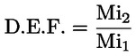
|
2.2. |
Bench Ageing Durability Test
|
2.3.1. Vehicles with Positive Ignition Engines
|
2.3.1.1. |
The following bench ageing procedure shall be applicable for positive-ignition vehicles including hybrid vehicles which use a catalyst as the principle after-treatment emission control device. The bench ageing procedure requires the installation of the catalyst-plus-oxygen sensor system on a catalyst ageing bench. Ageing on the bench shall be conducted by following the standard bench cycle (SBC) for the period of time calculated from the bench ageing time (BAT) equation. The BAT equation requires, as input, catalyst time-at-temperature data measured on the Standard Road Cycle (SRC), described in Appendix 3 to this Annex. |
|
2.3.1.2. |
Standard bench cycle (SBC). Standard catalyst bench ageing shall be conducted following the SBC. The SBC shall be run for the period of time calculated from the BAT equation. The SBC is described in Appendix 1 of this Annex. |
|
2.3.1.3. |
Catalyst time-at-temperature data. Catalyst temperature shall be measured during at least two full cycles of the SRC cycle as described in Appendix 3 to this Annex. Catalyst temperature shall be measured at the highest temperature location in the hottest catalyst on the test vehicle. Alternatively, the temperature may be measured at another location providing that it is adjusted to represent the temperature measured at the hottest location using good engineering judgement. Catalyst temperature shall be measured at a minimum rate of one hertz (one measurement per second). The measured catalyst temperature results shall be tabulated into a histogram with temperature groups of no larger than 25 °C. |
|
2.3.1.4. |
Bench-ageing time. Bench ageing time shall be calculated using the bench ageing time (BAT) equation as follows: te for a temperature bin = th e((R/Tr)–(R/Tv)) Total te = Sum of te over all the temperature groups Bench-Ageing Time = A (Total te) Where:
|
|
2.3.1.5. |
Effective reference temperature on the SBC. The effective reference temperature of the standard bench cycle (SBC) shall be determined for the actual catalyst system design and actual ageing bench which will be used using the following procedures: (a) Measure time-at-temperature data in the catalyst system on the catalyst ageing bench following the SBC. Catalyst temperature shall be measured at the highest temperature location of the hottest catalyst in the system. Alternatively, the temperature may be measured at another location providing that it is adjusted to represent the temperature measured at the hottest location. Catalyst temperature shall be measured at a minimum rate of one hertz (one measurement per second) during at least 20 minutes of bench ageing. The measured catalyst temperature results shall be tabulated into a histogram with temperature groups of no larger than 10 °C. (b) The BAT equation shall be used to calculate the effective reference temperature by iterative changes to the reference temperature (Tr) until the calculated ageing time equals or exceeds the actual time represented in the catalyst temperature histogram. The resulting temperature is the effective reference temperature on the SBC for that catalyst system and ageing bench. |
|
2.3.1.6. |
Catalyst Ageing Bench. The catalyst ageing bench shall follow the SBC and deliver the appropriate exhaust flow, exhaust constituents, and exhaust temperature at the face of the catalyst. All bench ageing equipment and procedures shall record appropriate information (such as measured A/F ratios and time-at-temperature in the catalyst) to assure that sufficient ageing has actually occurred. |
|
2.3.1.7. |
Required Testing. For calculating deterioration factors at least two Type 1 tests before bench ageing of the emission control hardware and at least two Type 1 tests after the bench-aged emission hardware is reinstalled have to be performed on the test vehicle. Additional testing may be conducted by the manufacturer. Calculation of the deterioration factors has to be done according to the calculation method as specified in Paragraph 6 of Annex 9 to UN/ECE Regulation No 83 as amended by this Regulation. |
2.3.2. Vehicles with Compression Ignition Engines
|
2.3.2.1. |
The following bench ageing procedure is applicable for compression-ignition vehicles including hybrid vehicles. The bench ageing procedure requires the installation of the aftertreatment system on a aftertreatment system ageing bench. Ageing on the bench is conducted by following the standard diesel bench cycle (SDBC) for the number of regenerations/desulphurisations calculated from the bench ageing duration (BAD) equation. |
|
2.3.2.2. |
Standard Diesel Bench Cycle (SDBC). Standard bench ageing is conducted following the SDBC. The SDBC shall be run for the period of time calculated from the bench ageing duration (BAD) equation. The SDBC is described in Appendix 2 of this Annex. |
|
2.3.2.3. |
Regeneration data. Regeneration intervals shall be measured during at least 10 full cycles of the SRC cycle as described in Appendix 3. As an alternative the intervals from the Ki determination may be used. If applicable, desulphurisation intervals shall also be considered based on manufacturer’s data |
|
2.3.2.4. |
Diesel bench-ageing duration. Bench ageing duration is calculated using the BAD equation as follows: Bench-Ageing Duration = number of regeneration and/or desulphurisation cycles (whichever is the longer) equivalent to 160 000 km of driving |
|
2.3.2.5. |
Ageing Bench. The ageing bench shall follow the SDBC and deliver appropriate exhaust flow, exhaust constituents, and exhaust temperature to the aftertreatment system inlet. The manufacturer shall record the number of regenerations/desulphurisations (if applicable) to assure that sufficient ageing has actually occurred. |
|
2.3.2.6. |
Required Testing. For calculating deterioration factors at least two Type 1 tests before bench ageing of the emission control hardware and at least two Type 1 tests after the bench-aged emission hardware is reinstalled have to be performed. Additional testing may be conducted by the manufacturer. Calculation of the deterioration factors shall be done according to the calculation method set out in Paragraph 6 of Annex 9 to UN/ECE Regulation No 83 and with the additional requirements contained in this Regulation. |
Appendix 1
Standard Bench Cycle (SBC)
1. Introduction
The standard ageing durability procedure consists of ageing a catalyst/oxygen sensor system on an ageing bench which follows the standard bench cycle (SBC) described in this Appendix. The SBC requires use of an ageing bench with an engine as the source of feed gas for the catalyst. The SBC is a 60-second cycle which is repeated as necessary on the ageing bench to conduct ageing for the required period of time. The SBC is defined based on the catalyst temperature, engine air/fuel (A/F) ratio, and the amount of secondary air injection which is added in front of the first catalyst.
2. Catalyst Temperature Control
|
2.1. |
Catalyst temperature shall be measured in the catalyst bed at the location where the highest temperature occurs in the hottest catalyst. Alternatively, the feed gas temperature may be measured and converted to catalyst bed temperature using a linear transform calculated from correlation data collected on the catalyst design and ageing bench to be used in the ageing process. |
|
2.2. |
Control the catalyst temperature at stoichiometric operation (01 to 40 seconds on the cycle) to a minimum of 800 °C (± 10 °C) by selecting the appropriate engine speed, load, and spark timing for the engine. Control the maximum catalyst temperature that occurs during the cycle to 890 °C (± 10 °C) by selecting the appropriate A/F ratio of the engine during the ‘rich’ phase described in the table below. |
|
2.3. |
If a low control temperature other than 800 °C is utilized, the high control temperature shall be 90 °C higher than the low control temperature.
Standard Bench Cycle (SBC)
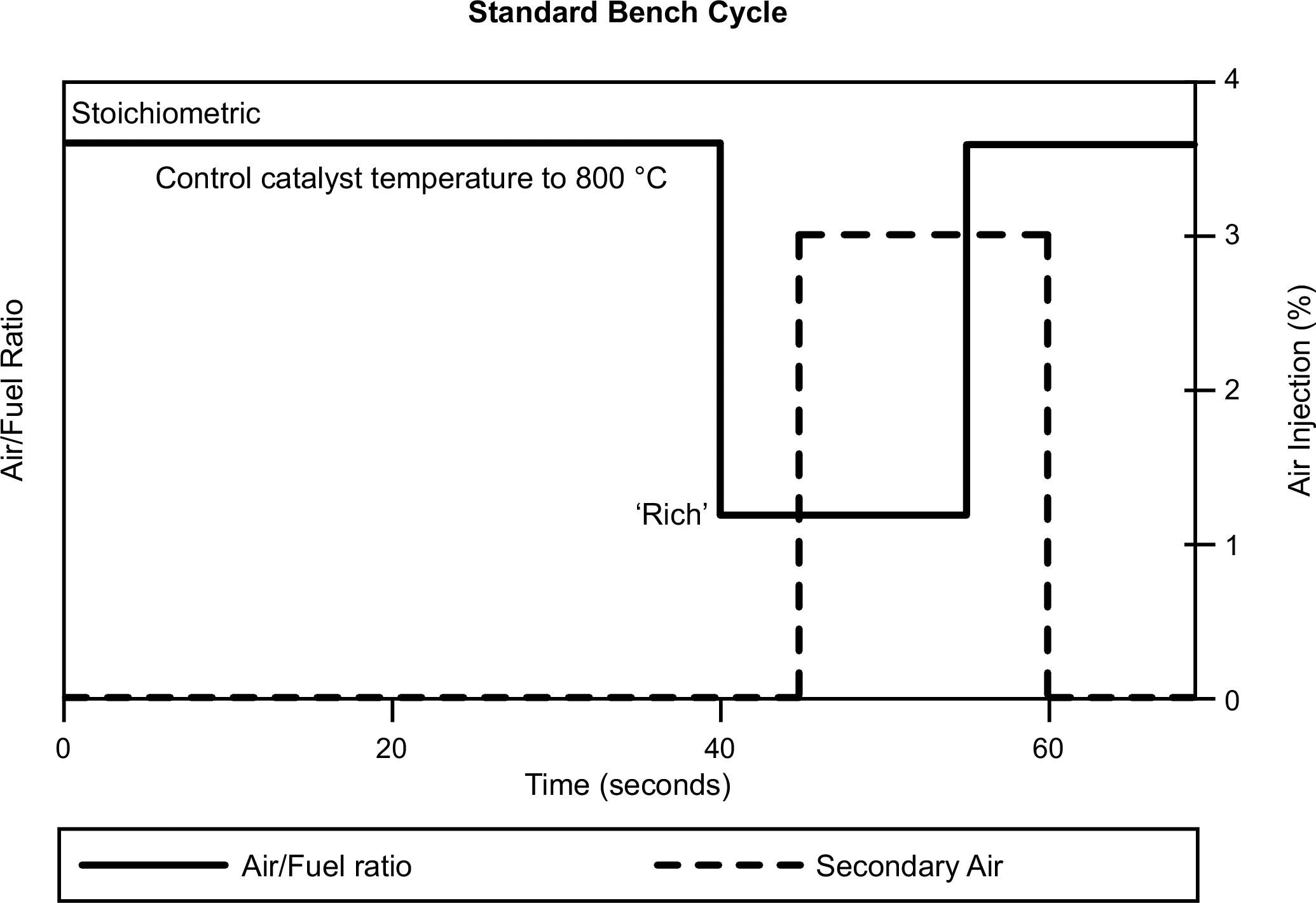
|
3. Ageing Bench Equipment and Procedures
|
3.1. |
Ageing Bench Configuration. The ageing bench shall provide the appropriate exhaust flow rate, temperature, air-fuel ratio, exhaust constituents and secondary air injection at the inlet face of the catalyst. The standard ageing bench consists of an engine, engine controller, and engine dynamometer. Other configurations may be acceptable (e.g. whole vehicle on a dynamometer, or a burner that provides the correct exhaust conditions), as long as the catalyst inlet conditions and control features specified in this Appendix are met. A single ageing bench may have the exhaust flow split into several streams providing that each exhaust stream meets the requirements of this appendix. If the bench has more than one exhaust stream, multiple catalyst systems may be aged simultaneously. |
|
3.2. |
Exhaust System Installation. The entire catalyst(s)-plus-oxygen sensor(s) system, together with all exhaust piping which connects these components, will be installed on the bench. For engines with multiple exhaust streams (such as some V6 and V8 engines), each bank of the exhaust system will be installed separately on the bench in parallel. For exhaust systems that contain multiple in-line catalysts, the entire catalyst system including all catalysts, all oxygen sensors and the associated exhaust piping will be installed as a unit for ageing. Alternatively, each individual catalyst may be separately aged for the appropriate period of time. |
|
3.3. |
Temperature Measurement. Catalyst temperature shall be measured using a thermocouple placed in the catalyst bed at the location where the highest temperature occurs in the hottest catalyst. Alternatively, the feed gas temperature just before the catalyst inlet face may be measured and converted to catalyst bed temperature using a linear transform calculated from correlation data collected on the catalyst design and ageing bench to be used in the ageing process. The catalyst temperature shall be stored digitally at the speed of 1 hertz (one measurement per second). |
|
3.4. |
Air/Fuel Measurement. Provisions shall be made for the measurement of the air/fuel (A/F) ratio (such as a wide-range oxygen sensor) as close as possible to the catalyst inlet and outlet flanges. The information from these sensors shall be stored digitally at the speed of 1 hertz (one measurement per second). |
|
3.5. |
Exhaust Flow Balance. Provisions shall be made to assure that the proper amount of exhaust (measured in grams/second at stoichiometry, with a tolerance of ± 5 grams/second) flows through each catalyst system that is being aged on the bench. The proper flow rate is determined based upon the exhaust flow that would occur in the original vehicle’s engine at the steady state engine speed and load selected for the bench ageing in Paragraph 3.6. of this Appendix. |
|
3.6. |
Setup. The engine speed, load, and spark timing are selected to achieve a catalyst bed temperature of 800 °C (± 10 °C) at steady-state stoichiometric operation. The air injection system is set to provide the necessary air flow to produce 3,0 % oxygen (± 0,1 %) in the steady-state stoichiometric exhaust stream just in front of the first catalyst. A typical reading at the upstream A/F measurement point (required in paragraph 5) is lambda 1,16 (which is approximately 3 % oxygen). With the air injection on, set the ‘Rich’ A/F ratio to produce a catalyst bed temperature of 890 °C (± 10 °C). A typical A/F value for this step is lambda 0,94 (approximately 2 % CO). |
|
3.7. |
Ageing Cycle. The standard bench ageing procedures use the standard bench cycle (SBC). The SBC is repeated until the amount of ageing calculated from the bench ageing time equation (BAT) is achieved. |
|
3.8. |
Quality Assurance. The temperatures and A/F ratio in paragraphs 3.3. and 3.4. of this appendix shall be reviewed periodically (at least every 50 hours) during ageing. Necessary adjustments shall be made to assure that the SBC is being appropriately followed throughout the ageing process. After the ageing has been completed, the catalyst time-at-temperature collected during the ageing process shall be tabulated into a histogram with temperature groups of no larger than 10 °C. The BAT equation and the calculated effective reference temperature for the ageing cycle according to Paragraph 2.3.1.4 of Annex VII will be used to determine if the appropriate amount of thermal ageing of the catalyst has in fact occurred. Bench ageing will be extended if the thermal effect of the calculated ageing time is not at least 95 % of the target thermal ageing. |
|
3.9. |
Startup and Shutdown. Care should be taken to assure that the maximum catalyst temperature for rapid deterioration (e.g., 1 050 °C) does not occur during startup or shutdown. Special low temperature startup and shutdown procedures may be used to alleviate this concern. |
4. Experimentally Determining the R-Factor for Bench Ageing Durability Procedures
|
4.1. |
The R-Factor is the catalyst thermal reactivity coefficient used in the bench ageing time (BAT) equation. Manufacturers may determine the value of R experimentally using the following procedures.
|


Appendix 2
Standard Diesel Bench Cycle (SDBC)
1. Introduction
For particulate filters, the number of regenerations is critical to the ageing process. For systems that require desulphurisation cycles (e.g. NOx storage catalysts), this process is also significant.
The standard diesel bench ageing durability procedure consists of ageing an aftertreatment system on an ageing bench which follows the standard bench cycle (SDBC) described in this Appendix. The SDBC requires use of an ageing bench with an engine as the source of feed gas for the system.
During the SDBC, the regeneration/desulphurisation strategies of the system shall remain in normal operating condition.
|
2. |
The Standard Diesel Bench Cycle reproduces the engine speed and load conditions that are encountered in the SRC cycle as appropriate to the period for which durability is to be determined. In order to accelerate the process of ageing, the engine settings on the test bench may be modified to reduce the system loading times. For example the fuel injection timing or EGR strategy may be modified. |
|
3. |
Ageing Bench Equipment and Procedures
|
Appendix 3
Standard Road Cycle (SRC)
Introduction
The standard road cycle (SRC) is a kilometre accumulation cycle. The vehicle may be run on a test track or on a kilometre accumulation dynamometer.
The cycle consists of 7 laps of a 6 km course. The length of the lap may be changed to accommodate the length of the mileage accumulation test track.
Standard Road cycle
|
Lap |
Description |
Typical acceleration rate m/s2 |
|
1 |
(start engine) idle 10 seconds |
0 |
|
1 |
Moderate acceleration to 48 km/h |
1,79 |
|
1 |
Cruise at 48 km/h for 1/4 lap |
0 |
|
1 |
Moderate deceleration to 32 km/h |
– 2,23 |
|
1 |
Moderate acceleration to 48 km/h |
1,79 |
|
1 |
Cruise at 48 km/h for 1/4 lap |
0 |
|
1 |
Moderate deceleration to stop |
– 2,23 |
|
1 |
Idle 5 seconds |
0 |
|
1 |
Moderate acceleration to 56 km/h |
1,79 |
|
1 |
Cruise at 56 km/h for 1/4 lap |
0 |
|
1 |
Moderate deceleration to 40 km/h |
– 2,23 |
|
1 |
Moderate acceleration to 56 km/h |
1,79 |
|
1 |
Cruise at 56 km/h for 1/4 lap |
0 |
|
1 |
Moderate deceleration to stop |
– 2,23 |
|
2 |
idle 10 seconds |
0 |
|
2 |
Moderate acceleration to 64 km/h |
1,34 |
|
2 |
Cruise at 64 km/h for 1/4 lap |
0 |
|
2 |
Moderate deceleration to 48 km/h |
– 2,23 |
|
2 |
Moderate acceleration to 64 km/h |
1,34 |
|
2 |
Cruise at 64 km/h for 1/4 lap |
0 |
|
2 |
Moderate deceleration to stop |
– 2,23 |
|
2 |
Idle 5 seconds |
0 |
|
2 |
Moderate acceleration to 72 km/h |
1,34 |
|
2 |
Cruise at 72 km/h for 1/4 lap |
0 |
|
2 |
Moderate deceleration to 56 km/h |
– 2,23 |
|
2 |
Moderate acceleration to 72 km/h |
1,34 |
|
2 |
Cruise at 72 km/h for 1/4 lap |
0 |
|
2 |
Moderate deceleration to stop |
– 2,23 |
|
3 |
idle 10 seconds |
0 |
|
3 |
Hard acceleration to 88 km/h |
1,79 |
|
3 |
Cruise at 88 km/h for 1/4 lap |
0 |
|
3 |
Moderate deceleration to 72 km/h |
– 2,23 |
|
3 |
Moderate acceleration to 88 km/h |
0,89 |
|
3 |
Cruise at 88 km/h for 1/4 lap |
0 |
|
3 |
Moderate deceleration to 72 km/h |
– 2,23 |
|
3 |
Moderate acceleration to 97 km/h |
0,89 |
|
3 |
Cruise at 97 km/h for 1/4 lap |
0 |
|
3 |
Moderate deceleration to 80 km/h |
– 2,23 |
|
3 |
Moderate acceleration to 97 km/h |
0,89 |
|
3 |
Cruise at 97 km/h for 1/4 lap |
0 |
|
3 |
Moderate deceleration to stop |
– 1,79 |
|
4 |
idle 10 seconds |
0 |
|
4 |
Hard acceleration to 129 km/h |
1,34 |
|
4 |
Coastdown to 113 km/h |
– 0,45 |
|
4 |
Cruise at 113 km/h for 1/2 lap |
0 |
|
4 |
Moderate deceleration to 80 km/h |
– 1,34 |
|
4 |
Moderate acceleration to 105 km/h |
0,89 |
|
4 |
Cruise at 105 km/h for 1/2 lap |
0 |
|
4 |
Moderate deceleration to 80 km/h |
– 1,34 |
|
5 |
Moderate acceleration to 121 km/h |
0,45 |
|
5 |
Cruise at 121 km/h for 1/2 lap |
0 |
|
5 |
Moderate deceleration to 80 km/h |
– 1,34 |
|
5 |
Light acceleration to 113 km/h |
0,45 |
|
5 |
Cruise at 113 km/h for 1/2 lap |
0 |
|
5 |
Moderate deceleration to 80 km/h |
– 1,34 |
|
6 |
Moderate acceleration to 113 km/h |
0,89 |
|
6 |
Coastdown to 97 km/h |
– 0,45 |
|
6 |
Cruise at 97 km/h for 1/2 lap |
0 |
|
6 |
Moderate deceleration to 80 km/h |
– 1,79 |
|
6 |
Moderate acceleration to 104 km/h |
0,45 |
|
6 |
Cruise at 104 km/h for 1/2 lap |
0 |
|
6 |
Moderate deceleration to stop |
– 1,79 |
|
7 |
idle 45 seconds |
0 |
|
7 |
Hard acceleration to 88 km/h |
1,79 |
|
7 |
Cruise at 88 km/h for 1/4 lap |
0 |
|
7 |
Moderate deceleration to 64 km/h |
– 2,23 |
|
7 |
Moderate acceleration to 88 km/h |
0,89 |
|
7 |
Cruise at 88 km/h for 1/4 lap |
0 |
|
7 |
Moderate deceleration to 64 km/h |
– 2,23 |
|
7 |
Moderate acceleration to 80 km/h |
0,89 |
|
7 |
Cruise at 80 km/h for 1/4 lap |
0 |
|
7 |
Moderate deceleration to 64 km/h |
– 2,23 |
|
7 |
Moderate acceleration to 80 km/h |
0,89 |
|
7 |
Cruise at 80 km/h for 1/4 lap |
0 |
|
7 |
Moderate deceleration to stop |
– 2,23 |
The standard road cycle is represented graphically in the following figure:

ANNEX VIII
VERIFYING THE AVERAGE EMISSIONS AT LOW AMBIENT TEMPERATURES
(TYPE 6 TEST)
1. INTRODUCTION
|
1.1. |
This Annex describes the equipment required and the procedure for the Type 6 test in order to verify the emissions at cold temperatures. |
2. GENERAL REQUIREMENTS
|
2.1. |
The general requirements for the Type 6 test are those set out in paragraph 5.3.5.1.1 to 5.3.5.3.2 of UN/ECE Regulation 83 with the exceptions specified below. |
|
2.2. |
The reference to ‘hydrocarbons’ in 5.3.5.1.4 of UN/ECE Regulation 83 shall be read as ‘total hydrocarbons’ |
|
2.3. |
The limit values referred to in point 5.3.5.2 of UN/ECE Regulation No 83 relate to the limit values set out in Annex 1, Table 4, to Regulation (EC) No 715/2007. |
3. TECHNICAL REQUIREMENTS
|
3.1. |
The technical requirements and specifications are those set out in section 2 to 6 of Annex 8 to UN/ECE Regulation No 83 with the exceptions described in the following sections. |
|
3.2. |
The reference to paragraph 3. of Annex 10 in paragraph 3.4.1. of Annex 8 to UN/ECE Regulation No 83 shall be understood as reference to to Section B of Annex IX to this Regulation. |
|
3.3. |
The references to ‘hydrocarbons’ shall be read as ‘total hydrocarbons’ in the following sections of Annex 8 to UN/ECE Regulation No 83: Paragraph 2.4.1 Paragraph 5.1.1 |
ANNEX IX
SPECIFICATIONS OF REFERENCE FUELS
A. REFERENCE FUELS
1. Technical data on fuels for testing vehicles with positive-ignition engines
Type: Petrol (E5)
|
Parameter |
Unit |
Limits (1) |
Test method |
|
|
Minimum |
Maximum |
|||
|
Research octane number, RON |
|
95,0 |
— |
EN 25164 prEN ISO 5164 |
|
Motor octane number, MON |
|
85,0 |
— |
EN 25163 prEN ISO 5163 |
|
Density at 15 °C |
kg/m3 |
743 |
756 |
EN ISO 3675 EN ISO 12185 |
|
Vapour pressure |
kPa |
56,0 |
60,0 |
EN ISO 13016-1 (DVPE) |
|
Water content |
% v/v |
|
0,015 |
ASTM E 1064 |
|
Distillation: |
|
|
|
|
|
— Evaporated at 70 °C, |
% v/v |
24,0 |
44,0 |
EN-ISO 3405 |
|
— evaporated at 100 °C, |
% v/v |
48,0 |
60,0 |
EN-ISO 3405 |
|
— evaporated at150 °C, |
% v/v |
82,0 |
90,0 |
EN-ISO 3405 |
|
— final boiling point, |
°C |
190 |
210 |
EN-ISO 3405 |
|
Residue |
% v/v |
— |
2,0 |
EN-ISO 3405 |
|
Hydrocarbon analysis: |
|
|
|
|
|
— olefins, |
% v/v |
3,0 |
13,0 |
ASTM D 1319 |
|
— aromatics, |
% v/v |
29,0 |
35,0 |
ASTM D 1319 |
|
— benzene, |
% v/v |
— |
1,0 |
EN 12177 |
|
— saturates, |
% v/v |
Report |
ASTM 1319 |
|
|
Carbon/hydrogen ratio |
|
Report |
|
|
|
Carbon/oxygen ratio |
|
Report |
|
|
|
Induction period (2) |
minutes |
480 |
— |
EN-ISO 7536 |
|
Oxygen content (3) |
% m/m |
Report |
EN 1601 |
|
|
Existent gum |
mg/ml |
— |
0,04 |
EN-ISO 6246 |
|
Sulphur content (4) |
mg/kg |
— |
10 |
EN ISO 20846 EN ISO 20884 |
|
Copper corrosion |
|
— |
Class 1 |
EN-ISO 2160 |
|
Lead content |
mg/l |
— |
5 |
EN 237 |
|
Phosphorus content (5) |
mg/l |
— |
1,3 |
ASTM D 3231 |
|
Ethanol (3) |
% v/v |
4,7 |
5,3 |
EN 1601 EN 13132 |
|
(1) The values quoted in the specifications are ‘true values’. In establishment of their limit values the terms of ISO 4259 Petroleum products — Determination and application of precision data in relation to methods of test have been applied and in fixing a minimum value, a minimum difference of 2R above zero has been taken into account; in fixing a maximum and minimum value, the minimum difference is 4R (R = reproducibility). Notwithstanding this measure, which is necessary for technical reasons, the manufacturer of fuels shall nevertheless aim at a zero value where the stipulated maximum value is 2R and at the mean value in the case of quotations of maximum and minimum limits. Should it be necessary to clarify whether a fuel meets the requirements of the specifications, the terms of ISO 4259 shall be applied. (2) The fuel may contain oxidation inhibitors and metal deactivators normally used to stabilise refinery gasoline streams, but detergent/dispersive additives and solvent oils shall not be added. (3) Ethanol meeting the specification of EN 15376 is the only oxygenate that shall be intentionally added to the reference fuel. (4) The actual sulphur content of the fuel used for the Type 1 test shall be reported. (5) There shall be no intentional addition of compounds containing phosphorus, iron, manganese, or lead to this reference fuel. |
||||
Type: Petrol (E10):
|
Parameter |
Unit |
Limits (1) |
Test method |
|
|
Minimum |
Maximum |
|||
|
Research octane number, RON (2) |
|
95,0 |
98,0 |
EN ISO 5164 |
|
Motor octane number, MON (2) |
|
85,0 |
89,0 |
EN ISO 5163 |
|
Density at 1 5 °C |
kg/m3 |
743,0 |
756,0 |
EN ISO 12185 |
|
Vapour pressure (DVPE) |
kPa |
56,0 |
60,0 |
EN 13016-1 |
|
Water content |
|
max 0,05 % v/v Appearance at – 7 °C: clear and bright |
EN 12937 |
|
|
Distillation: |
|
|
|
|
|
— evaporated at 70 °C |
% v/v |
34,0 |
46,0 |
EN ISO 3405 |
|
— evaporated at 100 °C |
% v/v |
54,0 |
62,0 |
EN ISO 3405 |
|
— evaporated at 150 °C |
% v/v |
86,0 |
94,0 |
EN ISO 3405 |
|
— final boiling point |
°C |
170 |
195 |
EN ISO 3405 |
|
Residue |
% v/v |
— |
2,0 |
EN ISO 3405 |
|
Hydrocarbon analysis: |
|
|
|
|
|
— olefins |
% v/v |
6,0 |
13,0 |
EN 22854 |
|
— aromatics |
% v/v |
25,0 |
32,0 |
EN 22854 |
|
— benzene |
% v/v |
— |
1,00 |
EN 22854 EN 238 |
|
— saturates |
% v/v |
report |
EN 22854 |
|
|
Carbon/hydrogen ratio |
|
report |
|
|
|
Carbon/oxygen ratio |
|
report |
|
|
|
Induction Period (3) |
minutes |
480 |
— |
EN ISO 7536 |
|
Oxygen content (4) |
% m/m |
3,3 |
3,7 |
EN 22854 |
|
Solvent washed gum (Existent gum content) |
mg/100 ml |
— |
4 |
EN ISO 6246 |
|
Sulphur content (5) |
mg/kg |
— |
10 |
EN ISO 20846 EN ISO 20884 |
|
Copper corrosion 3 hrs, 50 °C |
|
— |
class 1 |
EN ISO 2160 |
|
Lead content |
mg/l |
— |
5 |
EN 237 |
|
Phosphorus content (6) |
mg/l |
— |
1,3 |
ASTM D 3231 |
|
Ethanol (4) |
% v/v |
9,0 |
10,0 |
EN 22854 |
|
(1) The values quoted in the specifications are ‘true values’. In establishment of their limit values the terms of ISO 4259 Petroleum products - Determination and application of precision data in relation to methods of test have been applied and in fixing a minimum value, a minimum difference of 2R above zero has been taken into account; in fixing a maximum and minimum value, the minimum difference is 4R (R = reproducibility). Notwithstanding this measure, which is necessary for technical reasons, the manufacturer of fuels shall nevertheless aim at a zero value where the stipulated maximum value is 2R and at the mean value in the case of quotations of maximum and minimum limits. Should it be necessary to clarify whether a fuel meets the requirements of the specifications, the terms of ISO 4259 shall be applied. (2) A correction factor of 0,2 for MON and RON shall be subtracted for the calculation of the final result in accordance with EN 228:2008. (3) The fuel may contain oxidation inhibitors and metal deactivators normally used to stabilise refinery gasoline streams, but detergent/dispersive additives and solvent oils shall not be added. (4) Ethanol is the only oxygenate that shall be intentionally added to the reference fuel. The Ethanol used shall conform to EN 15376. (5) The actual sulphur content of the fuel used for the Type 1 test shall be reported. (6) There shall be no intentional addition of compounds containing phosphorus, iron, manganese, or lead to this reference fuel. (2) Equivalent EN/ISO methods will be adopted when issued for properties listed above. |
||||
Type: Ethanol (E85)
|
Parameter |
Unit |
Limits (1) |
Test method (2) |
|
|
Minimum |
Maximum |
|||
|
Research octane number, RON |
|
95 |
— |
EN ISO 5164 |
|
Motor octane number, MON |
|
85 |
— |
EN ISO 5163 |
|
Density at 15 °C |
kg/m3 |
Report |
ISO 3675 |
|
|
Vapour pressure |
kPa |
40 |
60 |
EN ISO 13016-1 (DVPE) |
|
mg/kg |
— |
10 |
EN ISO 20846 EN ISO 20884 |
|
|
Oxidation stability |
minutes |
360 |
|
EN ISO 7536 |
|
Existent gum content (solvent washed) |
mg/100ml |
— |
5 |
EN-ISO 6246 |
|
Appearance This shall be determined at ambient temperature or 15 °C whichever is higher. |
|
Clear and bright, visibly free of suspended or precipitated contaminants |
Visual inspection |
|
|
Ethanol and higher alcohols (7) |
% (V/V) |
83 |
85 |
EN 1601 EN 13132 EN 14517 |
|
Higher alcohols (C3-C8) |
% (V/V) |
— |
2 |
|
|
Methanol |
% (V/V) |
|
0,5 |
|
|
Petrol (5) |
% (V/V) |
Balance |
EN 228 |
|
|
Phosphorus |
mg/l |
0,3 (6) |
ASTM D 3231 |
|
|
Water content |
% (V/V) |
|
0,3 |
ASTM E 1064 |
|
Inorganic chloride content |
mg/l |
|
1 |
ISO 6227 |
|
pHe |
|
6,5 |
9 |
ASTM D 6423 |
|
Copper strip corrosion (3h at 50 °C) |
Rating |
Class 1 |
|
EN ISO 2160 |
|
Acidity, (as acetic acid CH3COOH) |
% (m/m) (mg/l) |
— |
0,005-40 |
ASTM D 1613 |
|
Carbon/hydrogen ratio |
|
report |
|
|
|
Carbon/oxygen ration |
|
report |
|
|
|
(1) The values quoted in the specifications are ‘true values’. In establishment of their limit values the terms of ISO 4259 Petroleum products — Determination and application of precision data in relation to methods of test have been applied and in fixing a minimum value, a minimum difference of 2R above zero has been taken into account; in fixing a maximum and minimum value, the minimum difference is 4R (R = reproducibility). Notwithstanding this measure, which is necessary for technical reasons, the manufacturer of fuels shall nevertheless aim at a zero value where the stipulated maximum value is 2R and at the mean value in the case of quotations of maximum and minimum limits. Should it be necessary to clarify whether a fuel meets the requirements of the specifications, the terms of ISO 4259 shall be applied. (2) In cases of dispute, the procedures for resolving the dispute and interpretation of the results based on test method precision, described in EN ISO 4259 shall be used. (3) In cases of national dispute concerning sulphur content, either EN ISO 20846 or EN ISO 20884 shall be called up similar to the reference in the national annex of EN 228. (4) The actual sulphur content of the fuel used for the Type 1 test shall be reported. (5) The unleaded petrol content can be determined as 100 minus the sum of the percentage content of water and alcohols (6) There shall be no intentional addition of compounds containing phosphorus, iron, manganese, or lead to this reference fuel. (7) Ethanol to meet specification of EN 15376 is the only oxygenate that shall be intentionally added to this reference fuel. |
||||
Type: LPG
|
Parameter |
Unit |
Fuel A |
Fuel B |
Test method |
|
Composition: |
|
|
|
ISO 7941 |
|
C3-content |
% vol |
30 ± 2 |
85 ± 2 |
|
|
C4-content |
% vol |
Balance |
Balance |
|
|
< C3, > C4 |
% vol |
Maximum 2 |
Maximum 2 |
|
|
Olefins |
% vol |
Maximum 12 |
Maximum 15 |
|
|
Evaporation residue |
mg/kg |
Maximum 50 |
Maximum 50 |
prEN 15470 |
|
Water at 0 °C |
|
Free |
Free |
prEN 15469 |
|
Total sulphur content |
mg/kg |
Maximum 10 |
Maximum 10 |
ASTM 6667 |
|
Hydrogen sulphide |
|
None |
None |
ISO 8819 |
|
Copper strip corrosion |
Rating |
Class 1 |
Class 1 |
ISO 6251 (1) |
|
Odour |
|
Characteristic |
Characteristic |
|
|
Motor octane number |
|
Minimum 89 |
Minimum 89 |
EN 589 Annex B |
|
(1) This method may not accurately determine the presence of corrosive materials if the sample contains corrosion inhibitors or other chemicals which diminish the corrosivity of the sample to the copper strip. Therefore, the addition of such compounds for the sole purpose of biasing the test method is prohibited. |
||||
Type: NG/Biomethane
|
Characteristics |
Units |
Basis |
Limits |
Test method |
|
|
minimum |
maximum |
||||
|
Reference fuel G20 |
|||||
|
Composition: |
|
|
|
|
|
|
Methane |
% mole |
100 |
99 |
100 |
ISO 6974 |
|
Balance (1) |
% mole |
— |
— |
1 |
ISO 6974 |
|
N2 |
% mole |
|
|
|
ISO 6974 |
|
Sulphur content |
mg/m3 (2) |
— |
— |
10 |
ISO 6326-5 |
|
Wobbe Index (net) |
MJ/m3 (3) |
48,2 |
47,2 |
49,2 |
|
|
Reference fuel G25 |
|||||
|
Composition: |
|
|
|
|
|
|
Methane |
% mole |
86 |
84 |
88 |
ISO 6974 |
|
Balance (1) |
% mole |
— |
— |
1 |
ISO 6974 |
|
N2 |
% mole |
14 |
12 |
16 |
ISO 6974 |
|
Sulphur content |
mg/m3 (2) |
— |
— |
10 |
ISO 6326-5 |
|
Wobbe Index (net) |
MJ/m3 (3) |
39,4 |
38,2 |
40,6 |
|
|
(1) Inerts (different from N2) + C2 + C2+. (2) Value to be determined at 293,2 K (20 °C) and 101,3 kPa. (3) Value to be determined at 273,2 K (0 °C) and 101,3 kPa. |
|||||
Type: Hydrogen for internal combustion engines
|
Characteristics |
Units |
Limits |
Test method |
|
|
minimum |
maximum |
|||
|
Hydrogen purity |
% mole |
98 |
100 |
ISO 14687-1 |
|
Total hydrocarbon |
μmol/mol |
0 |
100 |
ISO 14687-1 |
|
Water (1) |
μmol/mol |
0 |
ISO 14687-1 |
|
|
Oxygen |
μmol/mol |
0 |
ISO 14687-1 |
|
|
Argon |
μmol/mol |
0 |
ISO 14687-1 |
|
|
Nitrogen |
μmol/mol |
0 |
ISO 14687-1 |
|
|
CO |
μmol/mol |
0 |
1 |
ISO 14687-1 |
|
Sulphur |
μmol/mol |
0 |
2 |
ISO 14687-1 |
|
Permanent particulates (3) |
|
|
|
ISO 14687-1 |
|
(1) Not to be condensed. (2) Combined water, oxygen, nitrogen and argon: 1,900 μmol/mol. (3) The hydrogen shall not contain dust, sand, dirt, gums, oils, or other substances in an amount sufficient to damage the fuelling station equipment of the vehicle (engine) being fuelled. |
||||
Type: Hydrogen for fuel cell vehicles
|
Characteristics |
Units |
Limits |
Test method |
|
|
minimum |
maximum |
|||
|
Hydrogen fuel (1) |
% mole |
99,99 |
100 |
ISO 14687-2 |
|
Total gases (2) |
μmol/mol |
0 |
100 |
|
|
Total hydrocarbon |
μmol/mol |
0 |
2 |
ISO 14687-2 |
|
Water |
μmol/mol |
0 |
5 |
ISO 14687-2 |
|
Oxygen |
μmol/mol |
0 |
5 |
ISO 14687-2 |
|
Helium (He), Nitrogen (N2), Argon (Ar) |
μmol/mol |
0 |
100 |
ISO 14687-2 |
|
CO2 |
μmol/mol |
0 |
2 |
ISO 14687-2 |
|
CO |
μmol/mol |
0 |
0,2 |
ISO 14687-2 |
|
Total sulphur compounds |
μmol/mol |
0 |
0,004 |
ISO 14687-2 |
|
Formaldehyde (HCHO) |
μmol/mol |
0 |
0,01 |
ISO 14687-2 |
|
Formic acid (HCOOH) |
μmol/mol |
0 |
0,2 |
ISO 14687-2 |
|
Ammonia (NH3) |
μmol/mol |
0 |
0,1 |
ISO 14687-2 |
|
Total halogenated compounds |
μmol/mol |
0 |
0,05 |
ISO 14687-2 |
|
Particulates size |
μm |
0 |
10 |
ISO 14687-2 |
|
Particulates concentration |
μg/l |
0 |
1 |
ISO 14687-2 |
|
(1) The hydrogen fuel index is determined by subtracting the total content of non-hydrogen gaseous constituents listed in the table (Total gases), expressed in mole percent, from 100 mole percent. It is less than the sum of the maximum allowable limits of all non-hydrogen constituents shown in the Table. (2) The value of total gases is summation of the values of the non-hydrogen constituents listed in the table, except the particulates. |
||||
Type: H2NG
The hydrogen and the NG/biomethane fuels composing a H2NG mixture, must comply separately with their corresponding characteristics, expressed in this Annex.
2. Technical data on fuels for testing vehicles with compression ignition engines
Type: Diesel (B5)
|
Parameter |
Unit |
Limits (1) |
Test method |
|
|
Minimum |
Maximum |
|||
|
Cetane number (2) |
|
52,0 |
54,0 |
EN-ISO 5165 |
|
Density at 15 °C |
kg/m3 |
833 |
837 |
EN-ISO 3675 |
|
Distillation: |
|
|
|
|
|
— 50 % point |
°C |
245 |
— |
EN-ISO 3405 |
|
— 95 % point |
°C |
345 |
350 |
EN-ISO 3405 |
|
— final boiling point |
°C |
— |
370 |
EN-ISO 3405 |
|
Flash point |
°C |
55 |
— |
EN 22719 |
|
CFPP |
°C |
— |
– 5 |
EN 116 |
|
Viscosity at 40 °C |
mm2/s |
2,3 |
3,3 |
EN-ISO 3104 |
|
Polycyclic aromatic hydrocarbons |
% m/m |
2,0 |
6,0 |
EN 12916 |
|
Sulphur content (3) |
mg/kg |
— |
10 |
EN ISO 20846/EN ISO 20884 |
|
Copper corrosion |
|
— |
Class 1 |
EN-ISO 2160 |
|
Conradson carbon residue (10 % DR) |
% m/m |
— |
0,2 |
EN-ISO10370 |
|
Ash content |
% m/m |
— |
0,01 |
EN-ISO 6245 |
|
Water content |
% m/m |
— |
0,02 |
EN-ISO12937 |
|
Neutralisation (strong acid) number |
mg KOH/g |
— |
0,02 |
ASTM D 974 |
|
Oxidation stability (4) |
mg/ml |
— |
0,025 |
EN-ISO12205 |
|
Lubricity (HFRR wear scan diameter at 60 °C) |
μm |
— |
400 |
EN ISO 12156 |
|
h |
20,0 |
|
EN 14112 |
|
|
FAME (5) |
% v/v |
4,5 |
5,5 |
EN 14078 |
|
(1) The values quoted in the specifications are ‘true values’. In establishment of their limit values the terms of ISO 4259 Petroleum products — Determination and application of precision data in relation to methods of test have been applied and in fixing a minimum value, a minimum difference of 2R above zero has been taken into account; in fixing a maximum and minimum value, the minimum difference is 4R (R = reproducibility). Notwithstanding this measure, which is necessary for technical reasons, the manufacturer of fuels shall nevertheless aim at a zero value where the stipulated maximum value is 2R and at the mean value in the case of quotations of maximum and minimum limits. Should it be necessary to clarify whether a fuel meets the requirements of the specifications, the terms of ISO 4259 shall be applied. (2) The range for cetane number is not in accordance with the requirements of a minimum range of 4R. However, in the case of a dispute between fuel supplier and fuel user, the terms of ISO 4259 may be used to resolve such disputes provided replicate measurements, of sufficient number to archive the necessary precision, are made in preference to single determinations. (3) The actual sulphur content of the fuel used for the Type 1 test shall be reported. (4) Even though oxidation stability is controlled, it is likely that shelf life will be limited. Advice shall be sought from the supplier as to storage conditions and life. (5) FAME content to meet the specification of EN 14214. (6) Oxidation stability can be demonstrated by EN-ISO12205 or by EN 14112. This requirement shall be reviewed based on CEN/TC19 evaluations of oxidative stability performance and test limits. |
||||
Type: Diesel (B7):
|
Parameter |
Unit |
Limits (1) |
Test method |
|
|
Minimum |
Maximum |
|||
|
Cetane Index |
|
46,0 |
|
EN ISO 4264 |
|
Cetane number (2) |
|
52,0 |
56,0 |
EN ISO 5165 |
|
Density at 15 °C |
kg/m3 |
833,0 |
837,0 |
EN ISO 12185 |
|
Distillation: |
|
|
|
|
|
— 50 % point |
°C |
245,0 |
— |
EN ISO 3405 |
|
— 95 % point |
°C |
345,0 |
360,0 |
EN ISO 3405 |
|
— final boiling point |
°C |
— |
370,0 |
EN ISO 3405 |
|
Flash point |
°C |
55 |
— |
EN ISO 2719 |
|
Cloud point |
°C |
— |
– 10 |
EN 23015 |
|
Viscosity at 40 °C |
mm2/s |
2,30 |
3,30 |
EN ISO 3104 |
|
Polycyclic aromatic hydrocarbons |
% m/m |
2,0 |
4,0 |
EN 12916 |
|
Sulphur content |
mg/kg |
— |
10,0 |
EN ISO 20846 EN ISO 20884 |
|
Copper corrosion 3 hrs, 50 °C |
|
— |
Class 1 |
EN ISO 2160 |
|
Conradson carbon residue (10 % DR) |
% m/m |
— |
0,20 |
EN ISO 10370 |
|
Ash content |
% m/m |
— |
0,010 |
EN ISO 6245 |
|
Total contamination |
mg/kg |
— |
24 |
EN 12662 |
|
Water content |
mg/kg |
— |
200 |
EN ISO 12937 |
|
Acid number |
mg KOH/g |
— |
0,10 |
EN ISO 6618 |
|
Lubricity (HFRR wear scan diameter at 60 °C) |
μm |
— |
400 |
EN ISO 12156 |
|
Oxidation stability at 110 °C (3) |
h |
20,0 |
|
EN 15751 |
|
FAME (4) |
% v/v |
6,0 |
7,0 |
EN 14078 |
|
(1) The values quoted in the specifications are ‘true values’. In establishment of their limit values the terms of ISO 4259 Petroleum products – Determination and application of precision data in relation to methods of test have been applied and in fixing a minimum value, a minimum difference of 2R above zero has been taken into account; in fixing a maximum and minimum value, the minimum difference is 4R (R = reproducibility). Notwithstanding this measure, which is necessary for technical reasons, the manufacturer of fuels shall nevertheless aim at a zero value where the stipulated maximum value is 2R and at the mean value in the case of quotations of maximum and minimum limits. Should it be necessary to clarify whether a fuel meets the requirements of the specifications, the terms of ISO 4259 shall be applied. (2) The range for cetane number is not in accordance with the requirements of a minimum range of 4R. However, in the case of a dispute between fuel supplier and fuel user, the terms of ISO 4259 may be used to resolve such disputes provided replicate measurements, of sufficient number to archive the necessary precision, are made in preference to single determinations. (3) Even though oxidation stability is controlled, it is likely that shelf life will be limited. Advice shall be sought from the supplier as to storage conditions and life. (4) FAME content to meet the specification of EN 14214. |
||||
B. REFERENCE FUELS FOR TESTING EMISSIONS AT LOW AMBIENT TEMPERATURES — TYPE 6 TEST
Type: Petrol (E5)
|
Parameter |
Unit |
Limits (1) |
Test method |
|
|
Minimum |
Maximum |
|||
|
Research octane number, RON |
|
95,0 |
— |
EN 25164 prEN ISO 5164 |
|
Motor octane number, MON |
|
85,0 |
— |
EN 25163 prEN ISO 5163 |
|
Density at 15 °C |
kg/m3 |
743 |
756 |
ISO 3675 EN ISO 12185 |
|
Vapour pressure |
kPa |
56,0 |
95,0 |
EN ISO 13016-1 (DVPE) |
|
Water content |
% v/v |
|
0,015 |
ASTM E 1064 |
|
Distillation: |
|
|
|
|
|
— evaporated at 70 °C |
% v/v |
24,0 |
44,0 |
EN-ISO 3405 |
|
— evaporated at 100 °C |
% v/v |
50,0 |
60,0 |
EN-ISO 3405 |
|
— evaporated at 150 °C |
% v/v |
82,0 |
90,0 |
EN-ISO 3405 |
|
— final boiling point |
°C |
190 |
210 |
EN-ISO 3405 |
|
Residue |
% v/v |
— |
2,0 |
EN-ISO 3405 |
|
Hydrocarbon analysis: |
|
|
|
|
|
— olefins |
% v/v |
3,0 |
13,0 |
ASTM D 1319 |
|
— aromatics |
% v/v |
29,0 |
35,0 |
ASTM D 1319 |
|
— benzene |
% v/v |
— |
1,0 |
EN 12177 |
|
— saturates |
% v/v |
Report |
ASTM D 1319 |
|
|
Carbon/hydrogen ratio |
|
Report |
|
|
|
Carbon/oxygen ratio |
|
Report |
|
|
|
Induction period (2) |
minutes |
480 |
— |
EN-ISO 7536 |
|
Oxygen content (3) |
% m/m |
Report |
EN 1601 |
|
|
Existent gum |
mg/ml |
— |
0,04 |
EN-ISO 6246 |
|
Sulphur content (4) |
mg/kg |
— |
10 |
EN ISO 20846 EN ISO 20884 |
|
Copper corrosion |
|
— |
Class 1 |
EN-ISO 2160 |
|
Lead content |
mg/l |
— |
5 |
EN 237 |
|
Phosphorus content (5) |
mg/l |
— |
1,3 |
ASTM D 3231 |
|
Ethanol (3) |
% v/v |
4,7 |
5,3 |
EN 1601 EN 13132 |
|
(1) The values quoted in the specifications are ‘true values’. In establishment of their limit values the terms of ISO 4259 Petroleum — products Determination and application of precision data in relation to methods of test have been applied and in fixing a minimum value, a minimum difference of 2R above zero has been taken into account; in fixing a maximum and minimum value, the minimum difference is 4R (R = reproducibility). Notwithstanding this measure, which is necessary for technical reasons, the manufacturer of fuels shall nevertheless aim at a zero value where the stipulated maximum value is 2R and at the mean value in the case of quotations of maximum and minimum limits. Should it be necessary to clarify whether a fuel meets the requirements of the specifications, the terms of ISO 4259 shall be applied. (2) The fuel may contain oxidation inhibitors and metal deactivators normally used to stabilise refinery gasoline streams, but detergent/dispersive additives and solvent oils shall not be added. (3) Ethanol to meet specification of EN 15376 is the only oxygenate that shall be intentionally added to this reference fuel. (4) The actual sulphur content of the fuel used for the Type 6 test shall be reported. (5) There shall be no intentional addition of compounds containing phosphorus, iron, manganese, or lead to this reference fuel. |
||||
Type: Petrol (E10):
|
Parameter |
Unit |
Limits (1) |
Test method |
|
|
Minimum |
Maximum |
|||
|
Research octane number, RON (2) |
|
95,0 |
98,0 |
EN ISO 5164 |
|
Motor octane number, MON (2) |
|
85,0 |
89,0 |
EN ISO 5163 |
|
Density at 15 °C |
kg/m3 |
743,0 |
756,0 |
EN ISO 12185 |
|
Vapour pressure (DVPE) |
kPa |
56,0 |
95,0 |
EN 13016-1 |
|
Water content |
|
max 0,05 % v/v Appearance at – 7 °C: clear and bright |
EN 12937 |
|
|
Distillation: |
|
|
|
|
|
— evaporated at 70 °C |
% v/v |
34,0 |
46,0 |
EN ISO 3405 |
|
— evaporated at 100 °C |
% v/v |
54,0 |
62,0 |
EN ISO 3405 |
|
— evaporated at 150 °C |
% v/v |
86,0 |
94,0 |
EN ISO 3405 |
|
— final boiling point |
°C |
170 |
195 |
EN ISO 3405 |
|
Residue |
% v/v |
— |
2,0 |
EN ISO 3405 |
|
Hydrocarbon analysis: |
|
|
|
|
|
— olefins |
% v/v |
6,0 |
13,0 |
EN 22854 |
|
— aromatics |
% v/v |
25,0 |
32,0 |
EN 22854 |
|
— benzene |
% v/v |
— |
1,00 |
EN 22854 EN 238 |
|
— saturates |
% v/v |
report |
EN 22854 |
|
|
Carbon/hydrogen ratio |
|
report |
|
|
|
Carbon/oxygen ratio |
|
report |
|
|
|
Induction Period (3) |
minutes |
480 |
— |
EN ISO 7536 |
|
Oxygen content (4) |
% m/m |
3,3 |
3,7 |
EN 22854 |
|
Solvent washed gum (Existent gum content) |
mg/100 ml |
— |
4 |
EN ISO 6246 |
|
Sulphur content (5) |
mg/kg |
— |
10 |
EN ISO 20846 EN ISO 20884 |
|
Copper corrosion 3 hrs, 50 °C |
|
— |
class 1 |
EN ISO 2160 |
|
Lead content |
mg/l |
— |
5 |
EN 237 |
|
Phosphorus content (6) |
mg/l |
— |
1,3 |
ASTM D 3231 |
|
Ethanol (4) |
% v/v |
9,0 |
10,0 |
EN 22854 |
|
(1) The values quoted in the specifications are ‘true values’. In establishment of their limit values the terms of ISO 4259 Petroleum products - Determination and application of precision data in relation to methods of test have been applied and in fixing a minimum value, a minimum difference of 2R above zero has been taken into account; in fixing a maximum and minimum value, the minimum difference is 4R (R = reproducibility). Notwithstanding this measure, which is necessary for technical reasons, the manufacturer of fuels shall nevertheless aim at a zero value where the stipulated maximum value is 2R and at the mean value in the case of quotations of maximum and minimum limits. Should it be necessary to clarify whether a fuel meets the requirements of the specifications, the terms of ISO 4259 shall be applied. (2) A correction factor of 0,2 for MON and RON shall be subtracted for the calculation of the final result in accordance with EN 228:2008. (3) The fuel may contain oxidation inhibitors and metal deactivators normally used to stabilise refinery gasoline streams, but detergent/dispersive additives and solvent oils shall not be added. (4) Ethanol is the only oxygenate that shall be intentionally added to the reference fuel. The ethanol used shall conform to EN 15376. (5) The actual sulphur content of the fuel used for the Type 6 test shall be reported. (6) There shall be no intentional addition of compounds containing phosphorus, iron, manganese, or lead to this reference fuel. (2) Equivalent EN/ISO methods will be adopted when issued for properties listed above. |
||||
Type: Ethanol (E75)
|
Parameter |
Unit |
Limits (1) |
Test method (2) |
|
|
Minimum |
Maximum |
|||
|
Research octane number, RON |
|
95 |
— |
EN ISO 5164 |
|
Motor octane number, MON |
|
85 |
— |
EN ISO 5163 |
|
Density at 15 °C |
kg/m3 |
report |
EN ISO 12185 |
|
|
Vapour pressure |
kPa |
50 |
60 |
EN ISO 13016-1 (DVPE) |
|
mg/kg |
— |
10 |
EN ISO 20846 EN ISO 20884 |
|
|
Oxidation stability |
minutes |
360 |
— |
EN ISO 7536 |
|
Existent gum content (solvent washed) |
mg/100ml |
— |
4 |
EN ISO 6246 |
|
Appearance shall be determined at ambient temperature or 15 °C whichever is higher |
|
Clear and bright, visibly free of suspended or precipitated contaminants |
Visual inspection |
|
|
Ethanol and higher alcohols (7) |
% (V/V) |
70 |
80 |
EN 1601 EN 13132 EN 14517 |
|
Higher alcohols (C3 – C8) |
% (V/V) |
— |
2 |
|
|
Methanol |
|
— |
0,5 |
|
|
Petrol (5) |
% (V/V) |
Balance |
EN 228 |
|
|
Phosphorus |
mg/l |
0,30 (6) |
EN 15487 ASTM D 3231 |
|
|
Water content |
% (V/V) |
— |
0,3 |
ASTM E 1064 EN 15489 |
|
Inorganic chloride content |
mg/l |
— |
1 |
ISO 6227 — EN 15492 |
|
pHe |
|
6,50 |
9 |
ASTM D 6423 EN 15490 |
|
Copper strip corrosion (3h at 50 °C) |
Rating |
Class 1 |
|
EN ISO 2160 |
|
Acidity (as acetic acid CH3COOH) |
% (m/m) |
|
0,005 |
ASTM D1613 EN 15491 |
|
mg/l |
|
40 |
||
|
Carbon/hydrogen ration |
|
report |
|
|
|
Carbon/oxygen ration |
|
report |
|
|
|
(1) The values referred to in the specifications are ‘true values’. When establishing the value limits, the terms of ISO 4259 Petroleum products — Determination and application of precision data in relation to methods of test were applied. When fixing a minimum value, a minimum difference of 2R above zero was taken into account. When fixing a maximum and minimum value, the minimum difference used was 4R (R = reproducibility). Notwithstanding this procedure, which is necessary for technical reasons, fuel manufacturers shall aim for a zero value where the stipulated maximum value is 2R and for the mean value for quotations of maximum and minimum limits. Where it is necessary to clarify whether fuel meets the requirements of the specifications, the ISO 4259 terms shall be applied. (2) In cases of dispute, the procedures for resolving the dispute and interpretation of the results based on test method precision, described in EN ISO 4259 shall be used. (3) In cases of national dispute concerning sulphur content, either EN ISO 20846 or EN ISO 20884 shall be called up similar to the reference in the national annex of EN 228. (4) The actual sulphur content of the fuel used for the Type 6 test shall be reported. (5) The unleaded petrol content may be determined as 100 minus the sum of the percentage content of water and alcohols. (6) There shall be no intentional addition of compounds containing phosphorus, iron, manganese, or lead to this reference fuel. (7) Ethanol to meet specification of EN 15376 is the only oxygenate that shall be intentionally added to this reference fuel. |
||||
ANNEX X
EMISSIONS TEST PROCEDURE FOR HYBRID ELECTRIC VEHICLES (HEV)
1. INTRODUCTION
|
1.1. |
This annex sets out the additional specific provisions regarding type-approval of a hybrid electric vehicle (HEV). |
2. TECHNICAL REQUIREMENTS
|
2.1. |
The technical requirements and specifications shall be those set out in Annex 14 to UN/ECE Regulation No 83 with the exceptions described in the following section. |
|
2.2. |
The references to paragraph 5.3.1.4 in sections 3.1.2.6, 3.1.3.5, 3.2.2.7 and 3.2.3.5 of Annex 14 of UN/ECE Regulation No 83 shall be understood as references to Table 1 of Annex I of Regulation (EC) No 715/2007 for Euro 5 vehicles and Table 2 of Annex I of the Regulation (EC) No 715/2007 for Euro 6 vehicles. |
ANNEX XI
ON-BOARD DIAGNOSTICS (OBD) FOR MOTOR VEHICLES
1. INTRODUCTION
|
1.1. |
This Annex sets out the functional aspects of on-board diagnostic (OBD) systems for the control of emissions from motor vehicles. |
2. REQUIREMENTS AND TESTS
|
2.1. |
The requirements and tests for OBD systems are those specified in Section 3 of Annex 11 to UN/ECE Regulation 83. The exceptions to these requirements as well as additional requirements are described in the following sections. |
|
2.2. |
The durability distance mentioned in section 3.1 and 3.3.1 of Annex 11 to UN/ECE Regulation 83 shall be understood as reference to the requirements of Annex VII to this Regulation. |
|
2.3. |
The threshold limits specified in section 3.3.2 of Annex 11 to UN/ECE Regulation 83 shall be understood as reference to the tables below:
|
||||||||||||||||||||||||||||||||||||||||||||||||||||||||||||||||||||||||||||||||||||||||||||||||||||||||||||||||||||||||||||||||||||||||||||||||||||||||||||||||||||||||||||||||||||||||||||||||||||||||||||||||||||||||||||||||||||||||||||||||||||||||||||||||||||||||||||||||||||||||||||||||||||||||||||||||||||||||||||||||||||||||||||||||||||||||||||||||||||||||||||||||||
|
2.4. |
In addition to the provisions of section 3.2.1 of Annex 11 to UN/ECE Regulation 83 the manufacturer may temporarily disable the OBD system in the following conditions: (a) For flex fuel or mono/bi fuel gas vehicles during 1 minute after re-fuelling to allow for the recognition of fuel quality and composition by the ECU; (b) For bi fuel vehicles during 5 seconds after fuel switching to allow for readjusting engine parameters. The manufacturer may deviate from these time limits if it can demonstrate that stabilisation of the fuelling system after re-fuelling or fuel switching takes longer for justified technical reasons. In any case, the OBD system shall be re-enabled as soon as either the fuel quality and composition is recognised or the engine parameters are readjusted. |
|
2.5. |
Section 3.3.3.1 of Annex 11 to UNECE Regulation No 83 shall be understood as: The OBD system shall monitor the reduction in the efficiency of the catalytic converter with respect to emissions of NMHC and NOx. Manufacturers may monitor the front catalyst alone or in combination with the next catalyst(s) downstream. Each monitored catalyst or catalyst combination shall be considered malfunctioning when the emissions exceed the NMHC or NOx threshold limits provided for in Section 2.3 of this Annex. By way of derogation, the requirement of monitoring the reduction in the efficiency of the catalytic converter with respect to NOx emissions shall only apply as from the dates set out in Article 17. |
|
2.6. |
Section 3.3.3.3 of Annex 11 to UN/ECE Regulation 83 shall mean that the deterioration of all oxygen sensors fitted and used for monitoring malfunctions of the catalytic converter according to the requirements of this Annex shall be monitored. |
|
2.7. |
In addition to the requirements of section 3.3.3 of Annex 11 to UN/ECE Regulation 83, for direct injection positive ignition engines any malfunction, which may lead to emissions exceeding the particulate threshold limits provided for by section 2.3 of this Annex and which has to be monitored according to the requirements of this Annex for compression ignition engines, shall be monitored. |
|
2.8. |
In addition to the requirements of section 3.3.4 of Annex 11 to UN/ECE Regulation 83, malfunctions and the reduction in efficiency of the EGR system shall be monitored. |
|
2.9. |
In addition to the requirements of section 3.3.4 of Annex 11 to UN/ECE Regulation 83, malfunctions and the reduction in efficiency of a NOx aftertreatment system using a reagent and the reagent dosing sub-system shall be monitored. |
|
2.10. |
In addition to the requirements of section 3.3.4 of Annex 11 to UN/ECE Regulation 83, malfunctions and the reduction in efficiency of NOx aftertreatment not using a reagent shall be monitored. |
|
2.11. |
In addition to the requirements of section 6.3.2 of Appendix 1 to Annex 11 to UN/ECE Regulation 83, the manufacturer shall demonstrate that malfunctions of the EGR flow and cooler are detected by the OBD system during its approval test. |
|
2.12. |
References to ‘HC’ (hydrocarbons) shall be read as ‘NMHC’ (non-methane hydrocarbons) in section 6.4.1.2 of Appendix 1 to Annex 11 to UN/ECE Regulation 83. |
|
2.13. |
In addition to the requirements of section 6.5.1.3 of Appendix 1 to Annex 11 of UN/ECE Regulation 83, all data required to be stored in relation to OBD in-use performance according to the provisions of section 3.6 of Appendix 1 of this Annex shall be available through the serial data port on the standardised data link connector according to the specifications given in section 6.5.3 of Appendix 1 to Annex 11 of UN/ECE Regulation 83. |
|
2.14. |
Contrary to point 3.3.5 of Annex 11 to UN/ECE Regulation No 83, the following devices shall be monitored for total failure or removal if the latter resulted in exceeding the applicable emission limits: — as from 1 September 2011, a particulate trap fitted to compression ignition engines as a separate unit or integrated into a combined emission control device, — for vehicles certified against either the OBD threshold limits shown in the tables set out in point 2.3.3 or 2.3.4, a NOx aftertreatment system fitted to compression ignition engines as a separate unit or integrated into a combined emission control device, — for vehicles certified against either the OBD threshold limits shown in the tables set out in point 2.3.3 or 2.3.4, a diesel oxidation catalyst (DOC) fitted to compression ignition engines as a separate unit or integrated into a combined emission control device. The devices referred to in the first paragraph shall also be monitored for any failure that would result in exceeding the applicable OBD threshold limits. |
3. ADMINISTRATIVE PROVISIONS FOR DEFICIENCIES OF OBD SYSTEMS
|
3.1. |
In considering the request for granting type-approval to a vehicle with a deficiency or deficiencies as set out in Article 6(2), the approval authority shall determine whether compliance with the requirements of this Annex is infeasible or unreasonable. |
|
3.2. |
The approval authority shall take into consideration data from the manufacturer that details such factors as, but not limited to, technical feasibility, lead time and production cycles including phase-in or phase-out of engines or vehicle designs and programmed upgrades of computers, the extent to which the resultant OBD system will be effective in complying with the requirements of this Regulation and that the manufacturer has demonstrated an acceptable level of effort toward compliance with the requirements of this Regulation. |
|
3.3. |
The approval authority shall not accept any deficiency request that includes the complete lack of a required diagnostic monitor or of mandated recording and reporting of data related to a monitor. |
|
3.4. |
The approval authority will not accept any deficiency request that does not respect the OBD threshold limits in Section 2.3. |
|
3.5. |
In determining the identified order of deficiencies, deficiencies relating to sections 3.3.3.1, 3.3.3.2 and 3.3.3.3 of Annex 11 of UN/ECE Regulation 83 for positive-ignition engines and sections 3.3.4.1, 3.3.4.2 and 3.3.4.3 of Annex 11 of UN/ECE Regulation 83 for compression-ignition engines shall be identified first. |
|
3.6. |
Prior to or at the time of type-approval, no deficiency shall be granted in respect of the requirements of section 6.5, except section 6.5.3.4 of Appendix 1 to Annex 11 of UN/ECE Regulation 83. |
|
3.6. |
Deficiency period
|
|
3.7. |
The approval authority shall notify its decision in granting a deficiency request in accordance with Article 6(2). |
4. ACCESS TO OBD INFORMATION
|
4.1. |
Requirements for access to OBD information are specified in section 5 of Annex 11 to UN/ECE Regulation 83. The exceptions to these requirements are described in the following sections. |
|
4.2. |
References to Appendix 1 of Annex 2 to UN/ECE Regulation 83 shall be understood as references to Appendix 5 to Annex I to this Regulation. |
|
4.3. |
References to section 4.2.11.2.7.6 of Annex 1 to UN/ECE Regulation 83 shall be understood as references to 3.2.12.2.7.6 of Appendix 3 to Annex I to this Regulation. |
|
4.4. |
References to ‘contracting parties’ shall be understood as references to ‘member states’. |
|
4.5. |
References to approval granted under Regulation 83 shall be understood as references to type-approval granted under this Regulation and Council Directive 70/220/EEC ( 57 ). |
|
4.6. |
UN/ECE type-approval shall be understood as EC type-approval. |
Appendix 1
FUNCTIONAL ASPECTS OF ON-BOARD DIAGNOSTIC (OBD) SYSTEMS
1. INTRODUCTION
|
1.1. |
This Appendix describes the procedure of the test according to section 2 of this Annex. |
2. TECHNICAL REQUIREMENTS
|
2.1. |
The technical requirements and specifications shall be those set out in Appendix 1 to Annex 11 to UN/ECE Regulation No 83 with the exceptions and additional requirements as described in the following sections. |
|
2.2. |
The references to the OBD threshold limits set out in paragraph 3.3.2 to Annex 11 of UN/ECE Regulation 83 shall be understood as references to the limits set out in section 2.3 of this Annex. |
|
2.3. |
The reference fuels specified in paragraph 3.2 of Appendix 1 of Annex 11 of UN/ECE Regulation No 83 shall be understood as reference to the appropriate reference fuel specifications in Annex IX to this Regulation. |
|
2.4. |
The reference to Annex 11 in paragraph 6.5.1.4 of Appendix 1 of Annex 11 of UN/ECE Regulation No 83 shall be understood as reference to Annex XI to this Regulation. |
|
2.5. |
For vehicles approved to Euro 6 limit values contained in Table 2 of Annex 1 of Regulation (EC) No 715/2007, Section 6.5.3.1 of Appendix 1 of Annex 11 of UN/ECE Regulation 83 shall be replaced by: ‘For emissions-related diagnostics, the following standard shall be used as the on-board to off-board communications link: ISO 15765-4 “Road vehicles — Diagnostics on Controller Area Network (CAN) — Part 4: Requirements for emissions-related systems” dated 10 January 2005’ |
3. IN-USE PERFORMANCE
3.1. General Requirements
|
3.1.1. |
Each monitor of the OBD system shall be executed at least once per driving cycle in which the monitoring conditions as specified in section 3.2 are met. Manufacturers may not use the calculated ratio (or any element thereof) or any other indication of monitor frequency as a monitoring condition for any monitor. |
|
3.1.2. |
The in-use performance ratio (IUPR) of a specific monitor M of the OBD system referred to in Article 5(3) shall be: IUPRM = NumeratorM/DenominatorM |
|
3.1.3. |
Comparison of Numerator and Denominator gives an indication of how often a specific monitor is operating relative to vehicle operation. To ensure all manufacturers are tracking IUPRM in the same manner, detailed requirements are given for defining and incrementing these counters. |
|
3.1.4. |
If, according to the requirements of this Annex, the vehicle is equipped with a specific monitor M, IUPRM shall be greater or equal to the following minimum values: (i) 0,260 for secondary air system monitors and other cold start related monitors (ii) 0,520 for evaporative emission purge control monitors (iii) 0,336 for all other monitors |
|
3.1.5. |
Vehicles shall comply with the requirements of section 3.1.4 for a mileage of at least 160 000 km. By way of derogation, vehicles type approved, registered, sold or entered into service before the relevant dates given in Article 10(4), (5) of Regulation (EC) No 715/2007, shall have an IUPRM greater or equal 0,1 for all monitors M. ►M2 For new type approvals and new vehicles the monitor required by point 2.9 of this Annex shall have an IUPR greater or equal to 0,1 until three years after the dates specified in Article 10(4) and (5) of Regulation (EC) No 715/2007 respectively. ◄ |
|
3.1.6. |
The requirements of this section are deemed to be met for a particular monitor M, if for all vehicles of a particular OBD family manufactured in a particular calendar year the following statistical conditions hold: (a) The average IUPRM is equal or above the minimum value applicable to the monitor (b) More than 50 % of all vehicles have an IUPRM equal or above the minimum value applicable to the monitor. |
|
3.1.7. |
The manufacturer shall demonstrate to the approval authority and, upon request, to the Commission that these statistical conditions are satisfied for all monitors required to be reported by the OBD system according to point 3.6 of this Appendix not later than 18 months after the entry onto the market of the first vehicle type with IUPR in an OBD family and every 18 months thereafter. For this purpose, for OBD families consisting of more than 1 000 registrations in the Union, that are subject to sampling within the sampling period, the process described in Annex II shall be used without prejudice to the provisions of point 3.1.9 of this Appendix. In addition to the requirements set out in Annex II and regardless of the result of the audit described in Section 2 of Annex II, the authority granting the approval shall apply the in-service conformity check for IUPR described in Appendix 1 to Annex II in an appropriate number of randomly determined cases. ‘In an appropriate number of randomly determined cases’ means, that this measure has a dissuasive effect on non-compliance with the requirements of Section 3 of this Annex or the provision of manipulated, false or non-representative data for the audit. If no special circumstances apply and can be demonstrated by the type-approval authorities, random application of the in-service conformity check to 5 % of the type approved OBD families shall be considered as sufficient for compliance with this requirement. For this purpose, type-approval authorities may find arrangements with the manufacturer for the reduction of double testing of a given OBD family as long as these arrangements do not harm the dissuasive effect of the type-approval authority’s own in-service conformity check on non-compliance with the requirements of Section 3 of this Annex. Data collected by Member States during surveillance testing programmes may be used for in-service conformity checks. Upon request, type-approval authorities shall provide data on the audits and random in-service conformity checks performed, including the methodology used for identifying those cases, which are made subject to the random in-service conformity check, to the Commission and other type-approval authorities. |
|
3.1.8. |
For the entire test sample of vehicles the manufacturer must report to the relevant authorities all of the in-use performance data to be reported by the OBD system according to point 3.6 of this Appendix in conjunction with an identification of the vehicle being tested and the methodology used for the selection of the tested vehicles from the fleet. Upon request, the type-approval authority granting the approval shall make these data and the results of the statistical evaluation available to the Commission and other approval authorities. |
|
3.1.9. |
Public authorities and their delegates may pursue further tests on vehicles or collect appropriate data recorded by vehicles to verify compliance with the requirements of this Annex. |
|
3.1.10. |
Non-compliance with the requirements of point 3.1.6 established by tests described in points 3.1.7 or 3.1.9 shall be considered as an infringement subject to the penalties set out in Article 13 of Regulation (EC) No 715/2007. This reference does not limit the application of such penalties to other infringements of other provisions of Regulation (EC) No 715/2007 or this Regulation, which do no explicitly refer to Article 13 of Regulation (EC) No 715/2007. |
3.2. NumeratorM
|
3.2.1. |
The numerator of a specific monitor is a counter measuring the number of times a vehicle has been operated such that all monitoring conditions necessary for the specific monitor to detect a malfunction in order to warn the driver, as they have been implemented by the manufacturer, have been encountered. The numerator shall not be incremented more than once per driving cycle, unless there is reasoned technical justification. |
3.3. DenominatorM
|
3.3.1. |
The purpose of the denominator is to provide a counter indicating the number of vehicle driving events, taking into account special conditions for a specific monitor. The denominator shall be incremented at least once per driving cycle, if during this driving cycle such conditions are met and the general denominator is incremented as specified in section 3.5 unless the denominator is disabled according to section 3.7 of this Appendix. |
|
3.3.2. |
In addition to the requirements of section 3.3.1: (a) Secondary air system monitor denominator(s) shall be incremented if the commanded ‘on’ operation of the secondary air system occurs for a time greater than or equal to 10 seconds. For purposes of determining this commanded ‘on’ time, the OBD system may not include time during intrusive operation of the secondary air system solely for the purposes of monitoring; (b) Denominators of monitors of systems only active during cold start shall be incremented if the component or strategy is commanded ‘on’ for a time greater than or equal to 10 seconds; (c) The denominator(s) for monitors of Variable Valve Timing (VVT) and/or control systems shall be incremented if the component is commanded to function (e.g., commanded ‘on’, ‘open’, ‘closed’, ‘locked’, etc.) on two or more occasions during the driving cycle or for a time greater than or equal to 10 seconds, whichever occurs first; (d) For the following monitors, the denominator(s) shall be incremented by one if, in addition to meeting the requirements of this section on at least one driving cycle, at least 800 cumulative kilometres of vehicle operation have been experienced since the last time the denominator was incremented: (i) Diesel oxidation catalyst (ii) Diesel particulate filter; (e) Without prejudice to requirements for the increment of denominators of other monitors the denominators of monitors of the following components shall be incremented if and only if the driving cycle started with a cold start: (i) liquid (oil, engine coolant, fuel, SCR reagent) temperature sensors; (ii) clean air (ambient air, intake air, charge air, inlet manifold) temperature sensors; (iii) exhaust (EGR recirculation/cooling, exhaust gas turbo-charging, catalyst) temperature sensors; (f) The denominators of monitors of the boost pressure control system shall be incremented if the all of the following conditions are met: (i) the general denominator conditions are fulfilled; (ii) the boost pressure control system is active for a time greater than or equal to 15 seconds. |
|
3.3.3. |
For hybrid vehicles, vehicles that employ alternative engine start hardware or strategies (e.g. integrated starter and generators), or alternative fuel vehicles (e.g. dedicated, bi-fuel, or dual-fuel applications), the manufacturer may request the approval of the approval authority to use alternative criteria to those set forth in this section for incrementing the denominator. In general, the approval authority shall not approve alternative criteria for vehicles that only employ engine shut off at or near idle/vehicle stop conditions. Approval by the approval authority of the alternative criteria shall be based on the equivalence of the alternative criteria to determine the amount of vehicle operation relative to the measure of conventional vehicle operation in accordance with the criteria in this section. |
3.4. Ignition Cycle Counter
|
3.4.1. |
The ignition cycle counter indicates the number of ignition cycles a vehicle has experienced. The ignition cycle counter may not be incremented more than once per driving cycle. |
3.5. General Denominator
|
3.5.1. |
The general denominator is a counter measuring the number of times a vehicle has been operated. It shall be incremented within 10 seconds, if and only if, the following criteria are satisfied on a single driving cycle: — Cumulative time since engine start is greater than or equal to 600 seconds while at an elevation of less than 2 440 m above sea level and at an ambient temperature of greater than or equal to – 7 °C., — Cumulative vehicle operation at or above 40 km/h occurs for greater than or equal to 300 seconds while at an elevation of less than 2 440 m above sea level and at an ambient temperature of greater than or equal to – 7 °C., — Continuous vehicle operation at idle (i.e. accelerator pedal released by driver and vehicle speed less than or equal to 1,6 km/h) for greater than or equal to 30 seconds while at an elevation of less than 2 440 m above sea level and at an ambient temperature of greater than or equal to – 7 °C. |
3.6. Reporting and increasing counters
|
3.6.1. |
The OBD system shall report in accordance with the ISO 15031-5 specifications the ignition cycle counter and general denominator as well as separate numerators and denominators for the following monitors, if their presence on the vehicle is required by this Annex: — Catalysts (each bank to be reported separately), — Oxygen/exhaust gas sensors, including secondary oxygen sensors (each sensor to be reported separately), — Evaporative system, — EGR system, — VVT system, — Secondary air system, — Particulate filter, — NOx aftertreatment system (e.g. NOx adsorber, NOx reagent/catalyst system), — Boost pressure control system, |
|
3.6.2. |
For specific components or systems that have multiple monitors, which are required to be reported by this point (e.g. oxygen sensor bank 1 may have multiple monitors for sensor response or other sensor characteristics), the OBD system shall separately track numerators and denominators for each of the specific monitors except those monitoring for short circuit or open circuit failures and report only the corresponding numerator and denominator for the specific monitor that has the lowest numerical ratio. If two or more specific monitors have identical ratios, the corresponding numerator and denominator for the specific monitor that has the highest denominator shall be reported for the specific component. |
|
3.6.3. |
All counters, when incremented, shall be incremented by an integer of one. |
|
3.6.4. |
The minimum value of each counter is 0, the maximum value shall not be less than 65 535 , notwithstanding any other requirements on standardised storage and reporting of the OBD system. |
|
3.6.5. |
If either the numerator or denominator for a specific monitor reaches its maximum value, both counters for that specific monitor shall be divided by two before being incremented again according to the provisions set in sections 3.2 and 3.3. If the ignition cycle counter or the general denominator reaches its maximum value, the respective counter shall change to zero at its next increment according to the provisions set in sections 3.4 and 3.5, respectively. |
|
3.6.6. |
Each counter shall be reset to zero only when a non-volatile memory reset occurs (e.g. reprogramming event, etc.) or, if the numbers are stored in keep-alive memory (KAM), when KAM is lost due to an interruption in electrical power to the control module (e.g. battery disconnect, etc.). |
|
3.6.7. |
The manufacturer shall take measures to ensure that the values of numerator and denominator can not be reset or modified, except in cases provided for explicitly in this section. |
3.7. Disablement of Numerators and Denominators and of the General Denominator
|
3.7.1. |
Within 10 seconds of a malfunction being detected, which disables a monitor required to meet the monitoring conditions of this Annex (i.e. a pending or confirmed code is stored), the OBD system shall disable further incrementing of the corresponding numerator and denominator for each monitor that is disabled. When the malfunction is no longer detected (i.e., the pending code is erased through self-clearing or through a scan tool command), incrementing of all corresponding numerators and denominators shall resume within 10 seconds. |
|
3.7.2. |
Within 10 seconds of the start of a power take-off operation (PTO) operation that disables a monitor required to meet the monitoring conditions of this Annex, the OBD system shall disable further incrementing of the corresponding numerator and denominator for each monitor that is disabled. When the PTO operation ends, incrementing of all corresponding numerators and denominators shall resume within 10 seconds. |
|
3.7.3. |
The OBD system shall disable further incrementing of the numerator and denominator of a specific monitor within 10 seconds, if a malfunction of any component used to determine the criteria within the definition of the specific monitor’s denominator (i.e. vehicle speed, ambient temperature, elevation, idle operation, engine cold start, or time of operation) has been detected and the corresponding pending fault code has been stored. Incrementing of the numerator and denominator shall resume within 10 seconds when the malfunction is no longer present (e.g. pending code erased through self-clearing or by a scan tool command). |
|
3.7.4. |
The OBD system shall disable further incrementing of the general denominator within 10 seconds, if a malfunction has been detected of any component used to determine whether the criteria in section 3.5 are satisfied (i.e. vehicle speed, ambient temperature, elevation, idle operation, or time of operation) and the corresponding pending fault code has been stored. The general denominator may not be disabled from incrementing for any other condition. Incrementing of the general denominator shall resume within 10 seconds when the malfunction is no longer present (e.g., pending code erased through self-clearing or by a scan tool command). |
Appendix 2
ESSENTIAL CHARACTERISTICS OF THE VEHICLE FAMILY
1. PARAMETERS DEFINING THE OBD FAMILY
|
1.1. |
The OBD family means a manufacturer’s grouping of vehicles which, through their design, are expected to have similar exhaust emission and OBD system characteristics. Each engine of this family shall comply with the requirements of this Regulation. |
|
1.2. |
The OBD family may be defined by basic design parameters which shall be common to vehicles within the family. In some cases there may be interaction of parameters. These effects shall also be taken into consideration to ensure that only vehicles with similar exhaust emission characteristics are included within an OBD family. |
|
2. |
To this end, those vehicle types whose parameters described below are identical are considered to belong to the same engine/emission control/OBD system combination. Engine: — combustion process (i.e. positive-ignition/compression-ignition, two stroke/four stroke/rotary), — method of engine fuelling (i.e. single or multi-point fuel injection), — fuel type (i.e. petrol, diesel, flex fuel petrol/ethanol, flex fuel diesel/biodiesel, NG/biomethane, LPG, bi fuel petrol/NG/biomethane, bi fuel petrol/LPG), Emission control system: — type of catalytic converter (i. e. oxidation, three-way, heated catalyst, SCR, other), — type of particulate trap, — secondary air injection (i.e. with or without), — exhaust gas recirculation (i.e. with or without), OBD parts and functioning: — the methods of OBD functional monitoring, malfunction detection and malfunction indication to the vehicle driver. |
ANNEX XII
DETERMINATION OF CO2 EMISSIONS, FUEL CONSUMPTION, ELECTRIC ENERGY CONSUMPTION AND ELECTRIC RANGE
1. INTRODUCTION
This Annex sets out the requirements for the measurement of CO2 emissions, fuel consumption, electric energy consumption and electric range.
2. GENERAL REQUIREMENTS
|
2.1. |
The general specifications for conducting the tests and interpreting the results shall be those set out in Section 5 of UN/ECE Regulation 101 with the exceptions specified below. |
|
2.2. |
Test fuel
|
|
2.3. |
Point 5.2.4 of UNECE Regulation No 101 shall be understood as: (1) density: measured on the test fuel according to ISO 3675 or an equivalent method. For petrol, diesel, biodiesel and ethanol (E85 end E75), the density measured at 15 °C will be used; for LPG and natural gas/biomethane a reference density shall be used, as follows: 0,538 kg/litre for LPG, 0,654 kg/m3 for NG (mean value of G20 and G23 reference fuels at 15 °C.) (2) hydrogen-carbon-oxygen ratio: the following fixed values shall be used: C1H1,89O0,016 for petrol (E5), C1H1,93O0,033 for petrol (E10), C1H1,86O0,005 for diesel (B5), C1H1,86O0,007 for diesel (B7), C1H2,525 for LPG (liquefied petroleum gas), CH4 for NG (natural gas) and biomethane, C1H2,74O0,385 for ethanol (E85), C1H2,61O0,329 for ethanol (E75). |
3. TECHNICAL REQUIREMENTS
|
3.1. |
The technical requirements and specifications for the measurement of CO2 emissions, fuel consumption, electric energy consumption and electric range shall be those set out in Annexes 6 to 10 to UN/ECE Regulation 101 with the exceptions specified below. |
|
3.2. |
In Annex 6, section 1.3.5 of UN/ECE Regulation 101 the tyres used shall meet the same selection criteria as those specified for the type 1 emissions test, set out in Annex III section 3.5 of this Regulation. |
|
3.3. |
In Annex 6 of UN/ECE Regulation 101, section 1.4.3 shall be replaced by the following: 1.4.3. The fuel consumption, expressed in litres per 100 km (in the case of petrol (E5/E10), LPG, ethanol (E85) and diesel (B5/B7)), in m3 per 100 km (in the case of NG/biomethane and H2NG) or in kg per 100 km (in the case of hydrogen) is calculated by means of the following formulae: (a) for vehicles with a positive ignition engine fuelled with petrol (E5):
(b) for vehicles with a positive ignition engine fuelled with petrol (E10):
(c) for vehicles with a positive ignition engine fuelled with LPG:
If the composition of the fuel used for the test differs from the composition that is assumed for the calculation of the normalised consumption, on the manufacturer’s request a correction factor cf may be applied, as follows:
The correction factor cf, which may be applied, is determined as follows:
where: nactual = the actual H/C ratio of the fuel used (d) for vehicles with a positive ignition engine fuelled with NG/biomethane:
(e) for vehicles with a positive ignition engine fuelled with ethanol (E85):
(f) for vehicles with a compression ignition engine fuelled with diesel (B5):
(g) for vehicles with a compression ignition engine fuelled with diesel (B7):
(h) for vehicles with a positive ignition engine fuelled by H2NG:
(i) for vehicles fuelled by gaseous hydrogen:
Under previous agreement with the type-approval authority, and for vehicles fuelled either by gaseous or liquid hydrogen, the manufacturer may choose as alternative to the method above, either the formula
or a method according to standard protocols such as SAE J2572. In these formulae: FC = the fuel consumption in litre per 100 km (in the case of petrol, ethanol, LPG, diesel or biodiesel) in m3 per 100 km (in the case of natural gas and H2NG) or in kg per 100 km in the case of hydrogen. HC = the measured emission of hydrocarbons in g/km CO = the measured emission of carbon monoxide in g/km CO2 = the measured emission of carbon dioxide in g/km H2O = the measured emission of H2O in g/km H2 = the measured emission of H2 in g/km A = quantity of NG/biomethane within the H2NG mixture, expressed in per cent volume D = the density of the test fuel. In the case of gaseous fuels D is the density at 15 °C. d = the theoretical distance covered by a vehicle tested under the type 1 test in km. p1 = pressure in gaseous fuel tank before the operating cycle in Pa; p2 = pressure in gaseous fuel tank after the operating cycle in Pa; T1 = temperature in gaseous fuel tank before the operating cycle in K. T2 = temperature in gaseous fuel tank after the operating cycle in K. Z1 = compressibility factor of the gaseous fuel at p1 and T1 Z2 = compressibility factor of the gaseous fuel at p2 and T2 V = inner volume of the gaseous fuel tank in m 3 The compressibility factor shall be obtained from the following table:
In the case that the needed input values for p and T are not indicated in the table, the compressibility factor shall be obtained by linear interpolation between the compressibility factors indicated in the table, choosing the ones that are the closest to the sought value. |

|
3.4. |
In Annex 8 of UN/ECE Regulation 101, references to Annex 4 shall be understood as reference to Appendix 4 of Annex I of this Regulation. |
|
3.5. |
During the test cycle used for determining the CO2 emissions and fuel consumption of the vehicle the provision of point 3.14 of Annex III shall apply. |
4. TYPE-APPROVAL OF VEHICLES FITTED WITH ECO-INNOVATIONS
|
4.1. |
According to Article 11(1) of Regulation (EU) No 725/2011 for M1 vehicles and Article 11(1) of Regulation (EU) No 427/2014 for N1 vehicles, a manufacturer wishing to benefit from a reduction of its average specific CO2 emissions, as result of the savings achieved by one or more eco-innovations fitted in a vehicle, shall apply to an approval authority for an EC type-approval certificate of the vehicle fitted with the eco-innovation. |
|
4.2. |
The CO2 emissions savings from the vehicle fitted with an eco-innovation shall, for the purpose of type approval, be determined using the procedure and testing methodology specified in the Commission Decision approving the eco-innovation, in accordance with Article 10 of Regulation (EU) No 725/2011 for M1 vehicles, or Article 10 of Regulation (EU) No 427/2014 for N1 vehicles. |
|
4.3. |
The performance of the necessary tests for the determination of the CO2 emissions savings achieved by the eco-innovations shall be considered without prejudice to the demonstration of compliance of the eco-innovations with the technical prescriptions laid down in Directive 2007/46/EC, if applicable. |
|
4.4. |
The type approval shall not be granted if the eco-innovation vehicle does not show a minimum of 1 g CO2/km of emissions reduction with respect to the baseline vehicle, as referred to in article 5 of Regulation (EU) No 725/2011 for M1 vehicles, or Article 5 of Regulation (EU) No 427/2014 for N1 vehicles. |
5. DETERMINATION OF CO2 EMISSIONS AND FUEL CONSUMPTION FROM N1 VEHICLES SUBMITTED TO MULTI-STAGE TYPE-APPROVAL
|
5.1. |
For the purpose of determining the CO2 emissions and fuel consumption of a vehicle submitted to multi-stage type-approval, as defined in Article 3(7) of Directive 2007/46/EC, the base vehicle, as defined in Article 3(18) of that Directive, shall be tested in accordance with points 2 and 3 of this Annex. |
|
5.2. |
The reference mass to be used for the testing shall be the one resulting from the following formula:
In this formula:
|
|
5.3. |
The default added mass shall be calculated according to the following formula:
DAM: In this formula:
|
|
5.4. |
The multiplying factor shall be calculated according to the following formula:
In this formula:
|
|
5.5. |
The manufacturer of the base vehicle is responsible for the correct application of the requirements laid down in points 5.1 to 5.4. |
|
5.6. |
The manufacturer of the completed vehicle shall include, in the certificate of conformity, the information concerning the base vehicle, in accordance with Annex IX to Directive 2007/46/EC. |
|
5.7. |
In the case of vehicles submitted to individual vehicle approval, the individual approval certificate shall include the following information: (a) the CO2 emissions measured according to the methodology set out in points 5.1 to 5.4; (b) the mass of the completed vehicle in running order; (c) the identification code corresponding to the type, variant and version of the base vehicle; (d) the type-approval number of the base vehicle, including the extension number; (e) the name and address of the manufacturer of the base vehicle; (f) the mass of the base vehicle in running order. |
|
5.8. |
The procedure set out in points 5.1 to 5.7 shall apply to base vehicles of category N1, as defined in point 1.2.1 of Part A of Annex II to Directive 2007/46/EC, included in the scope of Regulation (EC) No 715/2007. |
ANNEX XIII
EC TYPE-APPROVAL OF REPLACEMENT POLLUTION CONTROL DEVICES AS SEPARATE TECHNICAL UNIT
1. INTRODUCTION
|
1.1. |
This Annex contains additional requirement for the type-approval as separate technical units of pollution control devices. |
2. GENERAL REQUIREMENTS
2.1. Marking
Original replacement pollution control devices shall bear at least the following identifications:
(a) the vehicle manufacturer’s name or trade mark;
(b) the make and identifying part number of the original replacement pollution control device as recorded in the information mentioned in point 2.3.
2.2. Documentation
Original replacement pollution control devices shall be accompanied by the following information:
(a) the vehicle manufacturer’s name or trade mark;
(b) the make and identifying part number of the original replacement pollution control device as recorded in the information mentioned in point 2.3;
(c) the vehicles for which the original replacement pollution control device is of a type covered by point 2.3 of the Addendum to Appendix 4 to Annex I, including, where applicable, a marking to identify if the original replacement pollution control device is suitable for fitting to a vehicle that is equipped with an on-board diagnostic (OBD) system;
(d) installation instructions, where necessary.
This information shall be available in the product catalogue distributed to points of sale by the vehicle manufacturer.
|
2.3. |
The vehicle manufacturer shall provide to the technical service and/or approval authority the necessary information in electronic format which makes the link between the relevant part numbers and the type-approval documentation. This information shall contain the following: (a) make(s) and type(s) of vehicle, (b) make(s) and type(s) of original replacement pollution control device, (c) part number(s) of original replacement pollution control device, (d) type-approval number of the relevant vehicle type(s). |
3. EC SEPARATE TECHNICAL UNIT TYPE-APPROVAL MARK
|
3.1. |
Every replacement pollution control device conforming to the type approved under this Regulation as a separate technical unit shall bear an EC type-approval mark. |
|
3.2. |
This mark shall consist of a rectangle surrounding the lower-case letter ‘e’ followed by the distinguishing number or letter(s) of the Member State which has granted the EC type-approval: 1. for Germany 2. for France 3. for Italy 4. for the Netherlands 5. for Sweden 6. for Belgium 7. for Hungary 8. for Czech Republic 9. for Spain 11. for the United Kingdom 12. for Austria 13. for Luxembourg 17. for Finland 18. for Denmark 19. for Romania 20. for Poland 21. for Portugal 23. for Greece 24. for Ireland 25. for Croatia 26. for Slovenia 27. for Slovakia 29. for Estonia 32. for Latvia 34. for Bulgaria 36. for Lithuania 49. for Cyprus 50. for Malta The EC type- approval mark shall also include in the vicinity of the rectangle the ‘base approval number’ contained in section 4 of the type-approval number referred to in Annex VII to Directive 2007/46/EC, preceded by the two figures indicating the sequence number assigned to the latest major technical amendment to Regulation (EC) No 715/2007 or this Regulation on the date EC type-approval for a separate technical unit was granted. For this Regulation, the sequence number is 00. |
|
3.3. |
The EC type-approval mark shall be affixed to the replacement pollution control device in such a way as to be clearly legible and indelible. It shall, wherever possible, be visible when the replacement pollution control device is installed on the vehicle. |
|
3.4. |
Appendix 3 to this Annex gives example of the EC type- approval mark. |
4. TECHNICAL REQUIREMENTS
|
4.1. |
The requirements for the type-approval of replacement pollution control devices shall be those of Section 5 of UN/ECE Regulation 103 with the exceptions set out in sections 4.1.1 to 4.1.4.
|
|
4.2. |
For vehicles with positive-ignition engines, if the THC and NMHC emissions measured during the demonstration test of a new original equipment catalytic converter, under paragraph 5.2.1 of UN/ECE Regulation 103, are higher than the values measured during the type-approval of the vehicle, the difference shall be added to the OBD threshold limits. The OBD threshold limits are specified in either: (a) point 3.3.2 of Annex 11 to UN/ECE Regulation 83 for replacement parts intended to be fitted on vehicles type-approved to Directive 70/220/EEC; or (b) point 2.3 of Annex XI of this Regulation for replacement parts intended to be fitted on vehicles type-approved to Regulation (EC) No 715/2007. |
|
4.3. |
The revised OBD threshold limits will apply during the tests of OBD compatibility set out in paragraphs 5.5 to 5.5.5 of UN/ECE Regulation 103. In particular, when the exceedance allowed in paragraph 1 of Appendix 1 to Annex 11 to UN/ECE Regulation 83 is applied. |
|
4.4. |
Requirements for replacement periodically regenerating systems 4.4.1. Requirements regarding emissions
4.4.2. Determination of the basis for comparison
4.4.3. Exhaust gas test with a replacement periodically regeneration system
4.4.4. Other requirements The requirements of paragraphs 5.2.3, 5.3, 5.4 and 5.5 of UN/ECE Regulation 103 shall apply to replacement periodically regenerating systems. In these paragraphs the words ‘catalytic converter’ shall be understood to mean ‘periodically regenerating system’. In addition the exceptions made to these paragraphs in section 4.1 of this annex shall also apply to periodically regenerating systems. |
5. DOCUMENTATION
|
5.1. |
Each replacement pollution control device shall be clearly and indelibly marked with the manufacturer’s name or trade mark and accompanied by the following information: (a) the vehicles (including year of manufacture) for which the replacement pollution control device is approved, including, where applicable, a marking to identify if the replacement pollution control device is suitable for fitting to a vehicle that is equipped with an on-board diagnostic (OBD) system; (b) installation instructions, where necessary. The information shall be available in the product catalogue distributed to points of sale by the manufacturer of replacement pollution control devices. |
6. CONFORMITY OF PRODUCTION
|
6.1. |
Measures to ensure the conformity of production shall be taken in accordance with the provisions laid down in Article 12 of Directive 2007/46/EC. |
|
6.2. |
Special provisions
|
Appendix 1
MODEL
Information document No …
relating to the EC type-approval of replacement pollution control devices
The following information, if applicable, must be supplied in triplicate and include a list of contents. Any drawings must be supplied in appropriate scale and sufficient detail on size A4 or on a folder of A4 format. Photographs, if any, must show sufficient detail.
If the systems, components or separate technical units have electronic controls, information concerning their performance must be supplied.
0. GENERAL
|
0.1. |
Make (trade name of manufacturer): |
|
0.2. |
Type:
|
|
0.5. |
Name and address of manufacturer: Name and address of authorised representative, if any: |
|
0.7. |
In the case of components and separate technical units, location and method of affixing of the EC approval mark: |
|
0.8. |
Address(es) of assembly plant(s): |
1. DESCRIPTION OF THE DEVICE
|
1.1. |
Make and type of the replacement pollution control device: |
|
1.2. |
Drawings of the replacement pollution control device, identifying in particular all the characteristics referred to under point 8 of Article 2 of [this Regulation]: |
|
1.3. |
Description of the vehicle type or types for which the replacement pollution control device is intended:
|
|
1.4. |
Description and drawings showing the position of the replacement pollution control device relative to the engine exhaust manifold(s): |
Appendix 2
MODEL EC TYPE-APPROVAL CERTIFICATE
(Maximum format: A4 (210 mm × 297 mm))
EC TYPE-APPROVAL CERTIFICATE
Communication concerning the:
— EC type-approval ( 59 ), ,
— extension of EC type-approval (59) , ,
— refusal of EC type-approval (59) , ,
— withdrawal of EC type-approval (59) , ,
of a type of component/separate technical unit (59)
with regard to Regulation (EC) No 715/2007, as implemented by Regulation (EC) No 692/2008.
Regulation (EC) No 715/2007 or Regulation (EC) No 692/2008 as last amended by
EC type-approval number: …
Reason for extension: …
SECTION I
|
0.1. |
Make (trade name of manufacturer): |
|
0.2. |
Type: |
|
0.3. |
Means of identification of type if marked on the component/separate technical unit ( 60 ):
|
|
0.5. |
Name and address of manufacturer: |
|
0.7. |
In the case of components and separate technical units, location and method of affixing of the EC approval mark: |
|
0.8. |
Name and address(es) of assembly plant(s): |
|
0.9. |
Name and address of manufacturer’s representative (if any): |
SECTION II
|
1. |
Additional information
|
|
2. |
Technical service responsible for carrying out the tests: |
|
3. |
Date of test report: |
|
4. |
Number of test report: |
|
5. |
Remarks: |
|
6. |
Place: |
|
7. |
Date: |
|
8. |
Signature: |
|
Attachments: |
Information package. Test report. |
Appendix 3
Example of the EC type-approval marks
(see point 5.2 of this Annex)
The above approval mark affixed to a component of a replacement pollution control device shows that the type concerned has been approved in France (e 2), pursuant to this Regulation. The first two digits of the approval number (00) indicate that this part was approved according to this Regulation. The following four digits (1234) are those allocated by the approval authority to the replacement pollution control device as the base approval number.
ANNEX XIV
Access to vehicle OBD and vehicle repair and maintenance information
1. INTRODUCTION
|
1.1. |
This Annex lays down technical requirements for the accessibility of vehicle OBD and vehicle repair and maintenance information. |
2. REQUIREMENTS
|
2.1. |
Vehicle OBD and vehicle repair and maintenance information available through websites shall follow the technical specifications of OASIS Document SC2-D5, Format of Automotive Repair Information, version 1.0, 28 May 2003 ( 61 ) and of Sections 3.2, 3,5, (excluding 3.5.2), 3,6, 3.7 and 3,8 of OASIS Document SC1-D2, Autorepair Requirements Specification, version 6.1, dated 10.1.2003 ( 62 ), using only open text and graphic formats or formats which can be viewed and printed using only standard software plug-ins that are freely available, easy to install, and which run under computer operating systems commonly in use. Where possible, keywords in the meta data shall conform to ISO 15031-2. Such information shall be always available, except as required for web-site maintenance purposes. Those requiring the right to duplicate or re-publish the information should negotiate directly with the manufacturer concerned. Information for training material shall also be available, but may be presented through other media than web-sites. Information on all parts of the vehicle, with which the vehicle, as identified by the vehicle identification number (VIN) and any additional criteria such as wheelbase, engine output, trim level or options, is equipped by the vehicle manufacturer and which can be replaced by spare parts offered by the vehicle manufacturer to its authorised repairers or dealers or third parties by means of reference to original equipment (OE) parts number, shall be made available in a database easily accessible to independent operators. This database shall comprise the VIN, OE parts numbers, OE naming of the parts, validity attributes (valid-from and valid-to dates), fitting attributes and where applicable structuring characteristics. The information on the database shall be regularly updated. The updates shall include in particular all modifications to individual vehicles after their production if this information is available to authorised dealers. |
|
2.2. |
Access to vehicle security features used by authorised dealers and repair shops shall be made available to independent operators under protection of security technology according to the following requirements: (i) data shall be exchanged ensuring confidentiality, integrity and protection against replay; (ii) the standard https//ssl-tls (RFC4346) shall be used; (iii) security certificates in accordance with ISO 20828 shall be used for mutual authentication of independent operators and manufacturers; (iv) the independent operator’s private key shall be protected by secure hardware. The Forum on Access to Vehicle Information provided for by paragraph 9 of Article 13 will specify the parameters for fulfilling these requirements according to the state-of-the-art. The independent operator shall be approved and authorised for this purpose on the basis of documents demonstrating that they pursue a legitimate business activity and have not been convicted of relevant criminal activity. |
|
2.3. |
Reprogramming of control units of vehicles manufactured later than 31 August 2010 shall be conducted in accordance with either ISO 22900 or SAE J2534, regardless of the date of type approval. For the validation of the compatibility of the manufacturer-specific application and the vehicle communication interfaces (VCI) complying to ISO 22900 or SAE J2534, the manufacturer shall offer either a validation of independently developed VCIs or the information, and loan of any special hardware, required for a VCI manufacturer to conduct such validation himself. The conditions of Article 7(1) of Regulation (EC) No 715/2007 apply to fees for such validation or information and hardware. For vehicles manufactured before 1 September 2010 the manufacturer may offer either full reprogramming in accordance with ISO 22900 or SAE J2534 or reprogramming via the sale or lease of its own proprietary tool. In the latter case independent operators must get access in a non-discriminatory, prompt and proportionate way, and the tool must be provided in a usable form. The provisions of Article 7 of Regulation (EC) No 715/2007 shall apply to fees for the access to these tools. |
|
2.4. |
All emission-related fault codes shall be consistent with Appendix 1 to Annex XI. |
|
2.5. |
For access to any vehicle OBD and vehicle repair and maintenance information other than that relating to secure areas of the vehicle, registration requirements for use of the manufacturer’s web site by an independent operator shall require only such information as is necessary to confirm how payment for the information is to be made. For information concerning access to secure areas of the vehicle, the independent operator shall present a certificate in accordance with ISO 20828 to identify himself and the organisation to which he belongs and the manufacturer shall respond with his own certificate in accordance with ISO 20828 to confirm to the independent operator that he is accessing a legitimate site of the intended manufacturer. Both parties shall keep a log of any such transactions indicating the vehicles and changes made to them under this provision. |
|
2.6. |
In the event that vehicle OBD and vehicle repair and maintenance information available on a manufacturer’s website does not contain specific relevant information to permit the proper design and manufacture of alternative fuels retrofit systems, then any interested alternative fuels retrofit system manufacturer shall be able to access the information required in paragraphs 0, 2, and 3 of Appendix 3 to Annex 1 by contacting the manufacturer directly with such a request. Contact details for that purpose shall be clearly indicated on the manufacturer’s website and the information shall be provided within 30 days. Such information need only be provided for alternative fuels retrofit systems that are subject to UN/ECE Regulation 115 or for alternative fuels retrofit components that form part of systems subject to UN/ECE Regulation 115, and need only be provided in response to a request that clearly specifies the exact specification of the vehicle model for which the information is required and that specifically confirms that the information is required for the development of alternative fuels retrofit systems or components subject to UN/ECE Regulation 115. |
|
2.7. |
Manufacturers shall indicate in their repair information websites the type-approval number by model. |
|
2.8. |
Manufacturers shall establish fees for hourly, daily, monthly, annual and per-transaction access to their repair and maintenance information websites, which are reasonable and proportionate. |
Appendix 1


ANNEX XV
IN-SERVICE CONFORMITY OF VEHICLES TYPE-APPROVED UNDER DIRECTIVE 70/220/EEC
1. CONFORMITY OF IN-SERVICE VEHICLES
|
1.1. |
An audit of in-service conformity shall be conducted by the approval authority on the basis of any relevant information in possession of the manufacturer, under procedures similar to those defined in Article 10(1) and (2) and in points 1 and 2 of Annex X to Directive 70/156/EEC. |
|
1.2. |
The Figure referred to under point 4 of Appendix 2 to this Annex and Figure 4/2 of Appendix 4 to UN/ECE Regulation 83 illustrate the procedure for in-service conformity checking. |
|
1.3. |
Parameters defining the in-service family The in-service family may be defined by basic design parameters which shall be common to vehicles within the family. Accordingly, those vehicle types which have in common, or within the stated tolerances, at least the parameters set out in points 1.3.1 to 1.3.11, can be considered as belonging to the same in-service family.
|
|
1.4. |
An audit of in-service conformity shall be conducted by the approval authority on the basis of information supplied by the manufacturer. Such information shall include, but is not limited to, the following:
|
|
2. |
The information gathered by the manufacturer shall be sufficiently comprehensive to ensure that in-service performance can be assessed for normal conditions of use as defined in section 1 and in a way representative of the manufacturer’s geographic penetration. For the purpose of this Regulation, the manufacturer shall not be obliged to carry out an audit of in-service conformity for a vehicle type if he can demonstrate to the satisfaction of the approval authority that the annual sales of that vehicle type in the Community are less than 5 000 per annum. |
|
3. |
On the basis of the audit referred to in Section 1.2 the approval authority shall adopt one of the following decisions and actions: (a) decide that the in-service conformity of a vehicle type or a vehicle in-service family is satisfactory and not take any further action; (b) decide that the data provided by the manufacturer is insufficient to reach a decision and request additional information or test data from the manufacturer; (c) decide that the in-service conformity of a vehicle type, that is part of an in-service family, is unsatisfactory and proceed to have such vehicle type tested in accordance with Appendix 1 to Annex I. Where the manufacturer has been permitted not to carry out an audit for a particular vehicle type in accordance with Section 2, the approval authority may proceed to have such vehicle types tested in accordance with Appendix 1 to Annex I.
|
Appendix 1
In-service conformity check
1. INTRODUCTION
This Appendix sets out the criteria for the in-service conformity control of vehicles type-approved under Directive 70/220/EEC.
2. SELECTION CRITERIA
The criteria for acceptance of a selected vehicle are defined in sections 2.1 to 2.8. Information shall be collected by the approval authority by vehicle examination and an interview with the owner/driver.
|
2.1. |
The vehicle shall belong to a vehicle type that is type-approved under Directive 70/220/EEC and covered by a certificate of conformity in accordance with Directive 70/156/EEC. The vehicle shall be registered and used in the European Community. |
|
2.2. |
The vehicle shall have been in service for at least 15 000 km or 6 months, whichever is the later, and for no more than 100 000 km or 5 years, whichever is the sooner. |
|
2.3. |
There shall be a maintenance record to show that the vehicle has been properly maintained, e. g. has been serviced in accordance with the manufacturer’s recommendations. |
|
2.4. |
The vehicle shall exhibit no indications of abuse (e. g. racing, overloading, misfuelling, or other misuse), or other factors (e. g. tampering) that could affect emission performance. In the case of vehicles fitted with an OBD system, the fault code and mileage information stored in the computer are taken into account. A vehicle shall not be selected for testing if the information stored in the computer shows that the vehicle has operated after a fault code was stored and a relatively prompt repair was not carried out. |
|
2.5. |
There shall have been no unauthorized major repair to the engine or major repair of the vehicle. |
|
2.6. |
The lead content and sulphur content of a fuel sample from the vehicle tank shall meet the applicable standards laid down in Directive 98/70/EC of the European Parliament and of the Council ( 63 ) and there shall be no evidence of misfuelling. Checks may be done in the tailpipe etc. |
|
2.7. |
There shall be no indication of any problem that might jeopardize the safety of laboratory personnel. |
|
2.8. |
All anti-pollution system components on the vehicle shall be in conformity with the applicable type-approval. |
3. DIAGNOSIS AND MAINTENANCE
Diagnosis and any normal maintenance necessary shall be performed on vehicles accepted for testing, prior to measuring exhaust emissions, in accordance with the procedure laid down in section 3.1 to 3.7.
|
3.1. |
The following checks shall be carried out: checks on air filter, all drive belts, all fluid levels, radiator cap, all vacuum hoses and electrical wiring related to the antipollution system for integrity; checks on ignition, fuel metering and pollution control device components for maladjustments and/or tampering. All discrepancies shall be recorded. |
|
3.2. |
The OBD system shall be checked for proper functioning. Any malfunction indications in the OBD memory shall be recorded and the requisite repairs shall be carried out. If the OBD malfunction indicator registers a malfunction during a preconditioning cycle, the fault may be identified and repaired. The test may be re-run and the results of that repaired vehicle used. |
|
3.3. |
The ignition system shall be checked and defective components replaced, for example spark plugs, cables, etc. |
|
3.4. |
The compression shall be checked. If the result is unsatisfactory the vehicle shall be rejected. |
|
3.5. |
The engine parameters shall be checked to the manufacturer’s specifications and adjusted if necessary. |
|
3.6. |
If the vehicle is within 800 km of a scheduled maintenance service, that service shall be performed according to the manufacturer’s instructions. Regardless of odometer reading, the oil and air filter may be changed at the request of the manufacturer. |
|
3.7. |
Upon acceptance of the vehicle, the fuel shall be replaced with appropriate emission test reference fuel, unless the manufacturer accepts the use of market fuel. |
4. IN-SERVICE TESTING
|
4.1. |
When a check on vehicles is deemed necessary, emission tests in accordance with Annex III to Directive 70/220/EEC shall be performed on pre-conditioned vehicles selected in accordance with the requirements of sections 2 and 3 of this Appendix. |
|
4.2. |
Vehicles equipped with an OBD system may be checked for proper in-service functionality of the malfunction indication, etc., in relation to levels of emissions (e. g. the malfunction indication limits defined in Annex XI to Directive 70/220/EEC) for the type-approved specifications. |
|
4.3. |
The OBD system may be checked, for example, for levels of emissions above the applicable limit values with no malfunction indication, systematic erroneous activation of the malfunction indication and identified faulty or deteriorated components in the OBD system. |
|
4.4. |
If a component or system operates in a manner not covered by the particulars in the type-approval certificate and/or information package for such vehicle types and such deviation has not been authorized under Article 5(3) or (4) of Directive 70/156/EEC, with no malfunction indication by the OBD, the component or system shall not be replaced prior to emission testing, unless it is determined that the component or system has been tampered with or abused in such a manner that the OBD does not detect the resulting malfunction. |
5. EVALUATION OF RESULTS
|
5.1. |
The test results are submitted to the evaluation procedure in accordance with Appendix 2 to this Annex. |
|
5.2. |
Test results shall not be multiplied by deterioration factors. |
6. PLAN OF REMEDIAL MEASURES
|
6.1. |
The approval authority shall request the manufacturer to submit a plan of remedial measures to remedy the non-compliance when more than one vehicle is found to be an outlying emitter that meets either of the following conditions: (a) meets the conditions set out in section 3.2.3 of Appendix 4 to UN/ECE Regulation 83 and both the type-approval authority and the manufacturer agree that the excess emission is due to the same cause, or (b) meets the conditions set out in section 3.2.4 of Appendix 4 to UN/ECE Regulation 83 and the type-approval authority has determined that the excess emission is due to the same cause. |
|
6.2. |
The plan of remedial measures shall be filed with the approval authority not later than 60 working days from the date of the notification referred to in section 6.1. The approval authority shall within 30 working days declare its approval or disapproval of the plan of remedial measures. However, where the manufacturer can demonstrate, to the satisfaction of the competent approval authority, that further time is required to investigate the non-compliance in order to submit a plan of remedial measures, an extension is granted. |
|
6.3. |
The remedial measures shall apply to all vehicles likely to be affected by the same defect. The need to amend the type-approval documents shall be assessed. |
|
6.4. |
The manufacturer shall provide a copy of all communications related to the plan of remedial measures, and shall also maintain a record of the recall campaign, and supply regular status reports to the approval authority. |
|
6.5. |
The plan of remedial measures shall include the requirements set out in points 6.5.1 to 6.5.11. The manufacturer shall assign a unique identifying name or number to the plan of remedial measures.
|
|
6.6. |
The manufacturer may be required to conduct reasonably designed and necessary tests on components and vehicles incorporating a proposed change, repair, or modification to demonstrate the effectiveness of the change, repair, or modification. |
|
6.7. |
The manufacturer shall be responsible for keeping a record of every vehicle recalled and repaired and the workshop which performed the repair. The approval authority shall have access to the record on request for a period of 5 years from the implementation of the plan of remedial measures. |
|
6.8. |
The repair and/or modification or addition of new equipment shall be recorded in a certificate supplied by the manufacturer to the vehicle owner. |
Appendix 2
Statistical procedure for in-service conformity testing
|
1. |
This procedure shall be used to verify the in-service conformity requirements for the type 1 test. The applicable statistical method shall be the one set out in Appendix 4 to UN/ECE Regulation No 83, with the exceptions set out in sections 2, 3 and 4. |
|
2. |
Footnote 1 shall not apply. |
|
3. |
In paragraphs 3.2.3.2.1 and 3.2.4.2 of Appendix 4 to UN/ECE Regulation No 83, the reference to paragraph 6 of Appendix 3 shall be understood as reference to Section 6 of Appendix 1 to Annex XV to this Regulation. |
|
4. |
In Figure 4/1. of Appendix 4 to UN/ECE Regulation No 83, the following shall apply: (a) the references to paragraph 8.2.1 shall be understood as reference to Section 1.1 of Annex XV to this Regulation; (b) the reference to Appendix 3 shall be understood as reference to Appendix 1 of Annex XV to this Regulation; (c) footnote 1 shall be understood as follows: In this case, TAA means the approval authority that granted the type-approval according to Directive 70/220/EC. |
ANNEX XVI
REQUIREMENTS FOR VEHICLES THAT USE A REAGENT FOR THE EXHAUST AFTERTREATMENT SYSTEM
1. INTRODUCTION
This Annex sets out the requirements for vehicles that rely on the use of a reagent for the aftertreatment system in order to reduce emissions.
2. REAGENT INDICATION
|
2.1. |
The vehicle shall include a specific indicator on the dashboard that informs the driver of low levels of reagent in the reagent storage tank and of when the reagent tank becomes empty. |
3. DRIVER WARNING SYSTEM
|
3.1. |
The vehicle shall include a warning system consisting of visual alarms that informs the driver when the reagent level is low, that the tank soon needs to be refilled, or the reagent is not of a quality specified by the manufacturer. The warning system may also include an audible component to alert the driver. |
|
3.2. |
The warning system shall escalate in intensity as the reagent approaches empty. It shall culminate in a driver notification that can not be easily defeated or ignored. It shall not be possible to turn off the system until the reagent has been replenished. |
|
3.3. |
The visual warning shall display a message indicating a low level of reagent. The warning shall not be the same as the warning used for the purposes of OBD or other engine maintenance. The warning shall be sufficiently clear for the driver to understand that the reagent level is low (e.g. ‘urea level low’, ‘AdBlue level low’, or ‘reagent low’). |
|
3.4. |
The warning system does not initially need to be continuously activated, however the warning shall escalate so that it becomes continuous as the level of the reagent approaches the point where the driver inducement system in Section 8 comes into effect. An explicit warning shall be displayed (e.g. ‘fill up urea’, ‘fill up AdBlue’, or ‘fill up reagent’). The continuous warning system may be temporarily interrupted by other warning signals providing important safety related messages. |
|
3.5. |
The warning system shall activate at a distance equivalent to a driving range of at least 2 400 km in advance to the reagent tank becoming empty. |
4. IDENTIFICATION OF INCORRECT REAGENT
|
4.1. |
The vehicle shall include a means of determining that a reagent corresponding to the characteristics declared by the manufacturer and recorded in Appendix 3 to Annex I to this Regulation is present on the vehicle. |
|
4.2. |
If the reagent in the storage tank does not correspond to the minimum requirements declared by the manufacturer the driver warning system in section 3 shall be activated and shall display a message indicating an appropriate warning (e.g. ‘incorrect urea detected’, ‘incorrect AdBlue detected’, or ‘incorrect reagent detected’). If the reagent quality is not rectified within 50 km of the activation of the warning system then the driver inducement requirements of section 8 shall apply. |
5. REAGENT CONSUMPTION MONITORING
|
5.1. |
The vehicle shall include a means of determining reagent consumption and providing off-board access to consumption information. |
|
5.2. |
Average reagent consumption and average demanded reagent consumption by the engine system shall be available via the serial port of the standard diagnostic connector. Data shall be available over the previous complete 2 400 km period of vehicle operation. |
|
5.3. |
In order to monitor reagent consumption, at least the following parameters within the vehicle shall be monitored: (a) the level of reagent in the on-vehicle storage tank; (b) the flow of reagent or injection of reagent as close as technically possible to the point of injection into an exhaust aftertreatment system. |
|
5.4. |
A deviation of more than 50 % between the average reagent consumption and the average demanded reagent consumption by the engine system over a period of 30 minutes of vehicle operation, shall result in the activation of the driver warning system in section 3, which shall display a message indicating an appropriate warning (e.g. ‘urea dosing malfunction’, ‘AdBlue dosing malfunction’, or ‘reagent dosing malfunction’). If the reagent consumption is not rectified within 50 km of the activation of the warning system then the driver inducement requirements of section 8 shall apply. |
|
5.5. |
In the case of interruption in reagent dosing activity the driver warning system as referred to in section 3 shall be activated, which shall display a message indicating an appropriate warning. This activation shall not be required where the interruption is demanded by the engine ECU because the vehicle operating conditions are such that the vehicle's emission performance does not require reagent dosing, provided that the manufacturer has clearly informed the approval authority when such operating conditions apply. If the reagent dosing is not rectified within 50 km of the activation of the warning system then the driver inducement requirements of section 8 shall apply. |
6. MONITORING NOx EMISSIONS
|
6.1. |
As an alternative to the monitoring requirements in section 4 and 5 manufacturers may use exhaust gas sensors directly to sense excess NOx levels in the exhaust. |
|
6.2. |
The manufacturer shall demonstrate that use of the sensors referred to in point 6.1 and any other sensors on the vehicle, results in the activation of the driver warning system as referred to in point 3, the display of a message indicating an appropriate warning (e.g. ‘emissions too high — check urea’, ‘emissions too high — check AdBlue’, ‘emissions too high — check reagent’), and the driver inducement system as referred to in point 8.3, when the situations referred to in points 4.2, 5.4 or 5.5 occur. For the purposes of this point these situations are presumed to occur: — in the case of vehicles approved to the Euro 5 emission limits of Table 1 of Annex I to Regulation (EC) No 715/2007, if the applicable NOx emission limit of that table multiplied by a factor of 1,5, is exceeded, — in the case of vehicles approved to the Euro 6 emission limits of Table 2 of Annex I to Regulation (EC) No 715/2007, if the applicable NOx OBD threshold limit of the tables set out in points 2.3.2, 2.3.3 or 2.3.4 of Annex XI is exceeded. NOx emissions during the test to demonstrate compliance with these requirements shall be no more than 20 % higher than the values referred to in the second paragraph. |
7. STORAGE OF FAILURE INFORMATION
|
7.1. |
Where reference is made to this point, non-erasable Parameter Identifiers (PID) shall be stored identifying the reason for and the distance travelled by the vehicle during the inducement system activation. The vehicle shall retain a record of the PID for at least 800 days or 30 000 km of vehicle operation. The PID shall be made available via the serial port of a standard diagnostic connector upon request of a generic scan tool according to the provisions of point 6.5.3.1 of Appendix 1 to Annex 11 to UN/ECE Regulation No 83 and point 2.5 of Appendix 1 to Annex XI to this Regulation. From the dates referred to in Article 17, the information stored in the PID shall be linked to the period of cumulated vehicle operation, during which it has occurred, with an accuracy of not less than 300 days or 10 000 km. |
|
7.2. |
Malfunctions in the reagent dosing system attributed to technical failures (e.g. mechanical or electrical faults) shall also be subject to the OBD requirements in Annex XI. |
8. DRIVER INDUCEMENT SYSTEM
|
8.1. |
The vehicle shall include a driver inducement system to ensure that the vehicle operates with a functioning emissions control system at all times. The inducement system shall be designed so as to ensure that the vehicle can not operate with an empty reagent tank. |
|
8.2. |
The inducement system shall activate at the latest when the level of reagent in the tank reaches a level equivalent to the average driving range of the vehicle with a complete tank of fuel. The system shall also activate when the failures in sections 4, 5 or 6 have occurred, depending on the NOx monitoring approach. The detection of an empty reagent tank and the failures mentioned in sections 4, 5 or 6 shall result in the failure information storage requirements of section 7 coming into effect. |
|
8.3. |
The manufacturer shall select which type of inducement system to install. The options for a system are described in following points 8.3.1, 8.3.2, 8.3.3 and 8.3.4.
|
|
8.4. |
Once the inducement system has fully activated and disabled the vehicle, the inducement system shall only be deactivated if the quantity of reagent added to the vehicle is equivalent to 2 400 km average driving range, or the failures specified in sections 4, 5, or 6 have been rectified. After a repair has been carried out to correct a fault where the OBD system has been triggered under point 7.2, the inducement system may be reinitialised via the OBD serial port (e.g. by a generic scan tool) to enable the vehicle to be restarted for self-diagnosis purposes. The vehicle shall operate for a maximum of 50 km to enable the success of the repair to be validated. The inducement system shall be fully reactivated if the fault persists after this validation. |
|
8.5. |
The driver warning system referred to in section 3 shall display a message indicating clearly: (a) the number of remaining restarts and/or the remaining distance; and (b) the conditions under which the vehicle can be restarted. |
|
8.6. |
The driver inducement system shall be deactivated when the conditions for its activation have ceased to exist. The driver inducement system shall not be automatically deactivated without the reason for its activation having been remedied. |
|
8.7. |
Detailed written information fully describing the functional operation characteristics of the driver inducement system shall be provided to the approval authority at the time of approval. |
|
8.8. |
As part of the application for type-approval under this Regulation, the manufacturer shall demonstrate the operation of the driver warning and inducement systems. |
9. INFORMATION REQUIREMENTS
|
9.1. |
The manufacturer shall provide all owners of new vehicles written information about the emission control system. This information shall state that if the vehicle emission control system is not functioning correctly, the driver shall be informed of a problem by the driver warning system and that the driver inducement system shall consequentially result in the vehicle being unable to start. |
|
9.2. |
The instructions shall indicate requirements for the proper use and maintenance of vehicles, including the proper use of consumable reagents. |
|
9.3. |
The instructions shall specify if consumable reagents have to be refilled by the vehicle operator between normal maintenance intervals. They shall indicate how the driver should refill the reagent tank. The information shall also indicate a likely rate of reagent consumption for that type of vehicle and how often it should be replenished. |
|
9.4. |
The instructions shall specify that use of, and refilling of, a required reagent of the correct specifications is mandatory for the vehicle to comply with the certificate of conformity issued for that vehicle type. |
|
9.5. |
The instructions shall state that it may be a criminal offence to use a vehicle that does not consume any reagent if it is required for the reduction of emissions. |
|
9.6. |
The instructions shall explain how the warning system and driver inducement systems work. In addition, the consequences of ignoring the warning system and not replenishing the reagent shall be explained. |
10. OPERATING CONDITIONS OF THE AFTERTREATMENT SYSTEM
Manufacturers shall ensure that the emission control system retains its emission control function during all ambient conditions regularly found in the European Union, especially at low ambient temperatures. This includes taking measures to prevent the complete freezing of the reagent during parking times of up to 7 days at 258 K (– 15 °C) with the reagent tank 50 % full. If the reagent has frozen, the manufacturer shall ensure that reagent shall be available for use within 20 minutes of the vehicle starting at 258 K (– 15 °C) measured inside the reagent tank, so as to ensure correct operation of the emission control system.
ANNEX XVII
AMENDMENTS TO REGULATION (EC) No 715/2007
Regulation (EC) No 715/2007 is amended as follows:
|
1. |
The following paragraph 6 shall be added to Article 10: ‘6. The 5,0 mg/km emission limit for mass of particulate matter referred to in Tables 1 and 2 of Annex I shall be effective from the applicable dates set out in paragraphs 1, 2 and 3. The 4,5 mg/km emission limit for mass of particulate matter and the particle number limit referred to in Tables 1 and 2 of Annex I shall be effective from 1 September 2011 for the type-approval on new types of vehicles and from 1 January 2013 for all new vehicles sold, registered or put into service in the Community.’ |
|
2. |
Tables 1 and 2 of Annex I are replaced by the following tables:
‘Table 1 Euro 5 Emission Limits
Table 2 Euro 6 Emission Limits
|
||||||||||||||||||||||||||||||||||||||||||||||||||||||||||||||||||||||||||||||||||||||||||||||||||||||||||||||||||||||||||||||||||||||||||||||||||||||||||||||||||||||||||||||||||||||||||||||||||||||||||||||||||||||||||||||||||||||||||||||||||||||||||||||||||||||||||||||||||||||||||||||||||||||||||||||||||||||||||||||||||||
ANNEX XVIII
SPECIAL PROVISIONS REGARDING ANNEX I TO COUNCIL DIRECTIVE 70/156/EEC
|
3.2.1.1. |
Working principle: positive ignition/compression ignition ( 64 ) Four stroke/two stroke/rotary cycle (64) |
|
3.2.2. |
Fuel: Diesel/Petrol/LPG/NG-Biomethane/Ethanol(E85)/Biodiesel/Hydrogen Four stroke/two stroke/rotary cycle (64)
|
|
3.2.4.2.3.3. |
Maximum fuel delivery Four stroke/two stroke/rotary cycle (64) ( 65 ): … mm3/stroke or cycle at an engine speed of: … min-1 or, alternatively, a characteristic diagram: |
|
3.2.4.2.9. |
Electronic controlled injection: yes/no (65)
|
|
3.2.4.3.4. |
System description, in the case of systems other than continuous injection give equivalent details:
|
|
3.2.4.3.5.1. |
Make(s): |
|
3.2.4.3.5.2. |
Type(s): |
|
3.2.8.2.1. |
Type: air-air/air-water (65) |
|
3.2.8.3. |
Intake depression at rated engine speed and at 100 % load (compression ignition engines only) Minimum allowable: kPa Maximum allowable: kPa |
|
3.2.9.3. |
Maximum allowable exhaust back pressure at rated engine speed and at 100 % load (compression ignition engines only): kPa |
|
3.2.11.1. |
Maximum lift of valves, angles of opening and closing, or timing details of alternative distribution systems, in relation to dead centres. For variable timing system, minimum and maximum timing: |
|
3.2.12.2. |
Additional pollution control devices (if any, and if not covered by another heading)
|
|
3.2.15.1. |
EC type-approval number according to Council Directive 70/221/EEC (OJ L 76, 6.4.1970, p. 23) (when the Directive will be amended to cover tanks for gaseous fuels) or approval number of UN/ECE Regulation 67’ |
|
3.2.16.1. |
EC type-approval number according to Directive 70/221/EEC (when the Directive will be amended to cover tanks for gaseous fuels) or approval number of UN/ECE Regulation 110: …’ |
|
3.4. |
Engines or motor combinations
|
|
3.5.2. |
Fuel consumption (provide for each reference fuel tested) |
|
6.6.1. |
Tyre/wheel combination(s) (a) for all tyre options indicate size designation, load-capacity index, speed category symbol, rolling resistance to ISO 28580 (where applicable) (b) for tyres of category Z intended to be fitted on vehicles whose maximum speed exceeds 300 km/h equivalent information shall be provided; for wheels indicate rim size(s) and off-set(s) |
|
9.1. |
Type of bodywork: (use codes defined in Annex II, section C): |
|
16. |
Access to vehicle repair and maintenance information
|
ANNEX XIX
SPECIAL PROVISIONS REGARDING ANNEX III TO COUNCIL DIRECTIVE 70/156/EEC
|
3.2.1.1. |
Working principle: positive ignition/compression ignition ( 66 ) Four stroke/two stroke/rotary cycle (66) |
|
3.2.2. |
Fuel: Diesel/Petrol/LPG/NG-Biomethane/Ethanol(E85)/Biodiesel/Hydrogen (66)
|
|
3.2.12.2. |
Additional pollution control devices (if any, and if not covered by another heading) |
|
3.4. |
Engines or motor combinations
|
|
6.6.1. |
Tyre/wheel combination(s) (a) for all tyre options indicate size designation, load-capacity index, speed category symbol, rolling resistance to ISO 28580 (where applicable) (b) for tyres of category Z intended to be fitted on vehicles whose maximum speed exceeds 300 km/h equivalent information shall be provided; for wheels indicate rim size(s) and off-set(s) |
|
9.1. |
Type of bodywork: (use codes defined in section C of Annex II): |
|
16. |
Access to vehicle repair and maintenance information
|
ANNEX XX
MEASUREMENT OF NET ENGINE POWER, NET POWER AND THE MAXIMUM 30 MINUTES POWER OF ELECTRIC DRIVE TRAIN
1. INTRODUCTION
This Annex sets out requirements for measuring net engine power, net power and the maximum 30 minutes power of electric drive train.
2. GENERAL SPECIFICATIONS
|
2.1 |
The general specifications for conducting the tests and interpreting the results are those set out in paragraph 5 of UNECE Regulation No 85 ( 67 ), with the exceptions specified in this Annex. |
|
2.2 |
Test fuel
Paragraphs 5.2.3.1., 5.2.3.2.1., 5.2.3.3.1., and 5.2.3.4. of UNECE Regulation No 85 shall be understood as follows: The fuel used shall be the one available on the market. In any case of dispute, the fuel shall be the appropriate reference fuel specified in Annex IX to the Regulation (EC) No 692/2008. |
|
2.3 |
Power correction factors
By way of derogation from paragraph 5.1 of Annex V to UNECE Regulation No 85, when a turbo-charged engine is fitted with a system which allows compensating the ambient conditions temperature and altitude, at the request of the manufacturer, the correction factors αa or αd shall be set to the value of 1. |
( 1 ) OJ L 171, 29.6.2007, p. 1.
( 2 ) OJ L 42, 23.2.1970, p. 1 Directive as last amended by Regulation (EC) No 715/2007
( 3 ) OJ L 263, 9.10.2007, p. 1.
( 4 ) OJ L 375, 27.12.2006, p. 223.
( 5 ) OJ L 326, 24.11.2006, p. 55
( 6 ) OJ L 76, 6.4.1970, p. 1.
( 7 ) OJ L 42, 23.2.1970, p. 1 Directive as last amended by Commission Directive 2007/37/EC
( 8 ) Specific test procedures for hydrogen and flex fuel biodiesel vehicles will be defined at a later stage.
( 9 ) OJ L 158, 19.6.2007, p. 34
( 10 ) OJ L 326, 24.11.2006, p. 1.
( 11 ) Delete where not applicable (there are cases where nothing needs to be deleted when more than one entry is applicable).
( 12 ) If the means of identification of type contains characters not relevant to describe the vehicle, component or separate technical unit types covered by this information document, such characters shall be represented in the documentation by the symbol.?. (e.g. ABC??123??).
( 13 ) Classified according to the definitions listed in Annex II, Section A.
( 14 ) (e) Where there is one version with a normal cab and another with a sleeper cab, both sets of masses and dimensions are to be stated.
( 15 ) The mass of the driver and, if applicable, of the crew member is assessed at 75 kg (subdivided into 68 kg occupant mass and 7 kg luggage mass according to ISO Standard 2416-1992), the fuel tank is filled to 90 % ant the other liquid containing systems (except those for used water) to 100 % of the capacity specified by the manufacturer.
( 16 ) For trailers or semi-trailers, and for vehicles coupled with a trailer or a semi-trailer, which exert a significant vertical load on the coupling device or the fifth wheel, this load, divided by standard acceleration of gravity, is included in the maximum technical permissible mass.
( 17 ) Please fill in here the upper and lower values for each variant.
( 18 ) In the case of non-conventional engines and systems, particulars equivalent to those referred to here shall be supplied by the manufacturer.
( 19 ) Vehicles can be fuelled with both petrol and a gaseous fuel but, where the petrol system is fitted for emergency purposes or starting only and of which the petrol tank cannot contain more than 15 litres of petrol, will be regarded for the test as vehicles which can only run a gaseous fuel.
( 20 ) This figure must be rounded off to the nearest tenth of a millimetre.
( 21 ) Specify the tolerance.
( 22 ) Determined in accordance with the requirements of Annex XX to this Regulation.
( 23 ) Vehicles can be fuelled with both petrol and a gaseous fuel but, where the petrol system is fitted for emergency purposes or starting only and of which the petrol tank cannot contain more than 15 litres of petrol, will be regarded for the test as vehicles which can only run on a gaseous fuel.
( 24 ) OJ L 72, 14.3.2008, p. 113.
( 25 ) OJ L 158, 19.6.2007, p. 34.
( 26 ) Determined in accordance with the requirements of Directive 80/1268/EEC.
( 27 ) If applicable.
( 28 ) Delete where not applicable.
( 29 ) Repeat the table for each reference fuel tested.
( 30 ) Expand the table if necessary, using one extra row per eco-innovation.
( 31 ) Delete where not applicable.
( 32 ) If applicable.
( 33 ) Repeat the table for each reference fuel tested.
( 34 ) Expand the table if necessary, using one extra row per eco-innovation.
( 35 ) (v) The specified particulars are to be given for any proposed variants.
( 36 ) Delete where not applicable (there are cases where nothing needs to be deleted when more than one entry is applicable)
( 37 ) OJ L 171, 29.6.2007, p. 1.
( 38 ) OJ L 199, 28.7.2008, p. 1
( 39 ) If the means of identification of type contains characters not relevant to describe the vehicle, component or separate technical unit types covered by this information, such characters shall be represented in the documentation by the symbol ‘?’ (e.g. ABC??123??)
( 40 ) As defined in Annex II, Section A
( 41 ) Delete where not applicable (there are cases where nothing needs to be deleted when more than one entry is applicable.)
( 42 ) For vehicles equipped with positive-ignition engines.
( 43 ) For compression-ignition engine vehicles
( 44 ) For vehicle fuelled with gas the unit is replaced by m3/km.
( 45 ) Measured over the combined cycle, i.e. Part One (urban) and Part Two (extra urban) together
( 46 ) Repeat the table for each reference fuel tested.
( 47 ) Expand the table if necessary, using one extra row per eco-innovation.
( 48 ) The general code of the eco-innovation(s) shall consist of the following elements, each separated by a blank space:
— Code of the type-approval authority as set out in Annex VII to Directive 2007/46/EC;
— Individual code of each eco-innovation fitted in the vehicle, indicated in chronological order of the Commission approval decisions.
— (E.g. the general code of three eco-innovations approved chronologically as 10, 15 and 16 and fitted to a vehicle certified by the German type approval authority should be: ‘e1 10 15 16’)
( 49 ) Delete where not applicable.
( 50 ) OJ L 350, 28.12.1998, p. 58.
( 51 ) OJ L 257, 25.9.2008, p. 14.
( 52 ) OJ L 135, 23.5.2008, p. 1.
( 53 ) Commission Regulation (EU) No 1230/2012 of 12 December 2012 implementing Regulation (EC) No 661/2009 of the European Parliament and of the Council with regard to type-approval requirements for masses and dimensions of motor vehicles and their trailers and amending Directive 2007/46/EC of the European Parliament and of the Council (OJ L 353, 21.12.2012, p. 31).
( 54 ) Regulation (EEC, Euratom) No 1182/71 of the Council of 3 June 1971 determining the rules applicable to periods, dates and time limits (OJ L 124, 8.6.1971, p. 1).
( 55 ) For hybrids, the total energy consumption shall be converted to CO2. The rules for this conversion will be introduced in a second step.
( 56 ) 1 for Germany; 2 for France; 3 for Italy; 4 for the Netherlands; 5 for Sweden; 6 for Belgium; 7 for Hungary; 8 for the Czech Republic; 9 for Spain; 11 for the United Kingdom; 12 for Austria; 13 for Luxembourg; 17 for Finland; 18 for Denmark; 19 for Romania; 20 for Poland; 21 for Portugal; 23 for Greece; 24 for Ireland. 25 for Croatia; 26 for Slovenia; 27 for Slovakia; 29 for Estonia; 32 for Latvia; 34 for Bulgaria; 36 for Lithuania; 49 for Cyprus; 50 for Malta.
( 57 ) OJ L 76, 6.4.1971, p. 1.
( 58 ) Delete where not applicable
( 59 ) Delete where not applicable
( 60 ) If the means of identification of type contains characters not relevant to describe the vehicle, component or separate technical unit types covered by this type-approval certificate such characters shall be represented in the document by the symbol:‘?’ (e.g. ABC??123??).
( 61 ) Available at: http://www.oasis-open.org/committees/download.php/2412/Draft%20Committee%20Specification.pdf
( 62 ) Available at: http://lists.oasis-open.org/archives/autorepair/200302/pdf00005.pdf
( 63 ) OJ L 350, 28.12.1998, p. 58.
( 64 ) Delete where not applicable (there are cases where nothing needs to be deleted when more than one entry is applicable.)
( 65 ) Specify the tolerance.
( 66 ) Delete where not applicable (there are cases where nothing needs to be deleted when more than one entry is applicable)
( 67 ) OJ L 326, 24.11.2006, p. 55.