Special edition in Czech: Chapter 07 Volume 006 P. 279 - 530
Special edition in Estonian: Chapter 07 Volume 006 P. 279 - 530
Special edition in Latvian: Chapter 07 Volume 006 P. 279 - 530
Special edition in Lithuanian: Chapter 07 Volume 006 P. 279 - 530
Special edition in Hungarian Chapter 07 Volume 006 P. 279 - 530
Special edition in Maltese: Chapter 07 Volume 006 P. 279 - 530
Special edition in Polish: Chapter 07 Volume 006 P. 279 - 530
Special edition in Slovak: Chapter 07 Volume 006 P. 279 - 530
Special edition in Slovene: Chapter 07 Volume 006 P. 279 - 530
Special edition in Bulgarian: Chapter 07 Volume 010 P. 3 - 254
Special edition in Romanian: Chapter 07 Volume 010 P. 3 - 254
Special edition in Croatian: Chapter 07 Volume 018 P. 11 - 262
English
Select your language
Official EU languages:
Access to European Union law
EUR-Lex
Access to European Union law
This document is an excerpt from the EUR-Lex website
Use quotation marks to search for an "exact phrase". Append an asterisk (*) to a search term to find variations of it (transp*, 32019R*). Use a question mark (?) instead of a single character in your search term to find variations of it (ca?e finds case, cane, care).
Need more search options? Use the
Advanced search
Document 32002R1360
Commission Regulation (EC) No 1360/2002 of 13 June 2002 adapting for the seventh time to technical progress Council Regulation (EEC) No 3821/85 on recording equipment in road transport (Text with EEA relevance)
Commission Regulation (EC) No 1360/2002 of 13 June 2002 adapting for the seventh time to technical progress Council Regulation (EEC) No 3821/85 on recording equipment in road transport (Text with EEA relevance)
Commission Regulation (EC) No 1360/2002 of 13 June 2002 adapting for the seventh time to technical progress Council Regulation (EEC) No 3821/85 on recording equipment in road transport (Text with EEA relevance)
OJ L 207, 5.8.2002, pp. 1–252
(ES, DA, DE, EL, EN, FR, IT, NL, PT, FI, SV) This document has been published in a special edition(s)
(CS, ET, LV, LT, HU, MT, PL, SK, SL, BG, RO, HR)
 No longer in force, Date of end of validity: 28/02/2014; Repealed by 32014R0165
- Date of document:
- 13/06/2002
- Date of effect:
- 25/08/2002; Entry into force Date pub. + 20 See Art 3
- Date of end of validity:
- 28/02/2014; Repealed by 32014R0165
- Author:
- European Commission
- Form:
- Regulation
- Additional information:
- EEA relevance, Extended to the EEA by 22003D0033
- Authentic language:
- Spanish, Danish, German, Greek, English, French, Italian, Dutch, Portuguese, Finnish, Swedish, Icelandic, Norwegian
- Treaty:
- Treaty establishing the European Economic Community
- Legal basis:
-
- 31985R3821 - A17 31985R3821 - A18
- Link
- Link
- Link
- Select all documents mentioning this document No data available in the table
- Modifies:
-
Relation Act Comment Subdivision concerned From To Modifies 31985R3821 Completion annex 2 25/08/2002 Modifies 31985R3821 Amendment annex 2 25/08/2002 Modifies 31998R2135 Replacement annex 25/08/2002
No data available in the table
- Modified by:
-
Relation Act Comment Subdivision concerned From To Corrected by 32002R1360R(01) (DA, DE, FI, FR, IT, NL, SV) Corrected by 32002R1360R(02) (EL, ES, PT) Corrected by 32002R1360R(03) (EN) Repealed by 32014R0165 - Link
- EUROVOC descriptor:
- Subject matter:
- Directory code:
-
- 07.20.40.10 Transport policy / Inland transport / Structural harmonisation / Technical and safety conditions
- 07.20.40.20 Transport policy / Inland transport / Structural harmonisation / Social conditions
Language
HTML
PDF
Official Journal
|
5.8.2002 |
EN |
Official Journal of the European Union |
L 207/1 |
COMMISSION REGULATION (EC) No 1360/2002
of 13 June 2002
adapting for the seventh time to technical progress Council Regulation (EEC) No 3821/85 on recording equipment in road transport
(Text with EEA relevance)
THE COMMISSION OF THE EUROPEAN COMMUNITIES,
Having regard to the Treaty establishing the European Community,
Having regard to Council Regulation (EEC) No 3821/85 of 20 December 1985 on recording equipment in road transport (1), as last amended by Regulation (EC) No 2135/98 (2), and in particular Articles 17 and 18 thereof,
Whereas:
|
(1) |
The technical specifications of Annex I (B) to Regulation (EEC) No 3821/85 should be adapted to technical progress paying particular attention to the overall security of the system and to the interoperability between the recording equipment and the driver cards. |
|
(2) |
The adaptation of the equipment also requires an adaptation of Annex II to Regulation (EEC) No 3821/85, which defines the marks and approval certificates. |
|
(3) |
The Committee set up by Article 18 of Regulation (EEC) No 3821/85 did not deliver an opinion on the measures provided in the proposal and the Commission therefore submitted to the Council a proposal relating to these measures. |
|
(4) |
On the expiry of the period laid down in Article 18(5)(b) of Regulation (EEC) No 3821/85, the Council had not acted and it is accordingly for the Commission to adopt these measures, |
HAS ADOPTED THIS REGULATION:
Article 1
The Annex to Regulation (EC) No 2135/98 is replaced by the Annex to this Regulation.
Article 2
Annex II to Regulation (EEC) No 3821/85 is amended as follows:
|
1. |
Chapter I, item 1, first subparagraph is amended as follows:
|
|
2. |
Chapter I, item 1, second subparagraph is amended as follows:
|
|
3. |
Chapter I, item 2 is amended as follows:
|
|
4. |
In Chapter II, the following wording is added to the title ‘FOR PRODUCTS COMPLIANT WITH ANNEX I’. |
|
5. |
The following Chapter III is added: ‘III. APPROVAL CERTIFICATE FOR PRODUCTS COMPLIANT WITH ANNEX I B A State, having granted approval, shall issue the applicant with an approval certificate, the model of which is given below. When informing other Member States of approvals issued or, if the occasion should arise, withdrawn, a Member State shall use copies of that certificate.
|
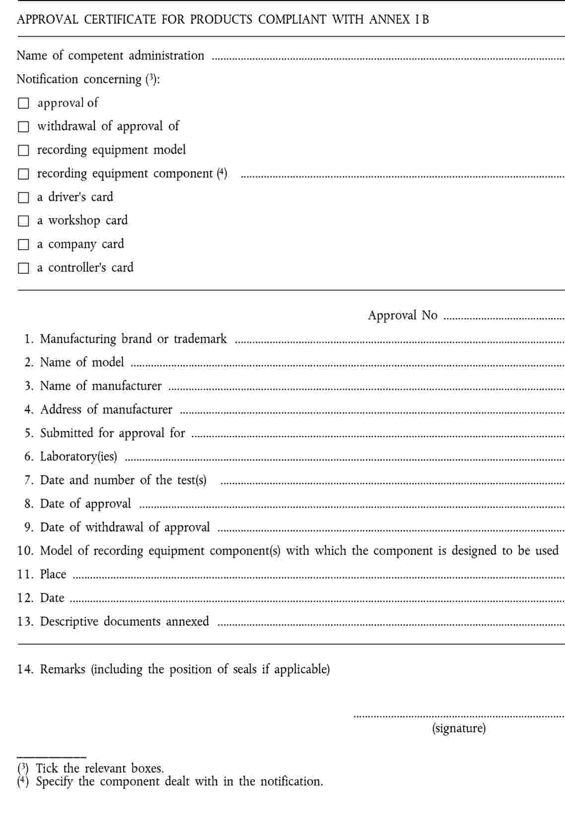 ’
’Article 3
This Regulation shall enter into force on the twentieth day following that of its publication in the Official Journal of the European Communities.
This Regulation shall be binding in its entirety and directly applicable in all Member States.
Done at Brussels, 13 June 2002.
For the Commission
Loyola DE PALACIO
Vice-President
(1) OJ L 370, 31.12.1985, p. 8.
(2) OJ L 274, 9.10.1998, p. 1.
ANNEX
‘
’
ANNEX I B
REQUIREMENTS FOR CONSTRUCTION, TESTING, INSTALLATION AND INSPECTION
CONTENTS
|
I. |
DEFINITIONS | 8 |
|
II. |
GENERAL CHARACTERISTICS AND FUNCTIONS OF THE RECORDING EQUIPMENT | 12 |
|
1. |
General characteristics | 12 |
|
2. |
Functions | 12 |
|
3. |
Modes of operation | 13 |
|
4. |
Security | 14 |
|
III. |
CONSTRUCTION AND FUNCTIONAL REQUIREMENTS FOR RECORDING EQUIPMENT | 14 |
|
1. |
Monitoring cards insertion and withdrawal | 14 |
|
2. |
Speed and distance measurement | 14 |
|
2.1. |
Measurement of distance travelled | 15 |
|
2.2. |
Measurement of speed | 15 |
|
3. |
Time measurement | 15 |
|
4. |
Monitoring driver activities | 16 |
|
5. |
Monitoring driving status | 16 |
|
6. |
Drivers manual entries | 16 |
|
6.1. |
Entry of places where daily work periods begin and/or end | 16 |
|
6.2. |
Manual entry of driver activities | 16 |
|
6.3. |
Entry of specific conditions | 18 |
|
7. |
Company locks management | 18 |
|
8. |
Monitoring control activities | 18 |
|
9. |
Detection of events and/or faults | 18 |
|
9.1. |
“Insertion of a non valid card“ event | 18 |
|
9.2. |
“Card conflict“ event | 19 |
|
9.3. |
“Time overlap“ event | 19 |
|
9.4. |
“Driving without an appropriate card“ event | 19 |
|
9.5. |
“Card insertion while driving“ event | 19 |
|
9.6. |
“Last card session not correctly closed“ event | 19 |
|
9.7. |
“Over speeding“event | 19 |
|
9.8. |
“Power supply interruption“ event | 20 |
|
9.9. |
“Motion data error“ event | 20 |
|
9.10. |
“Security breach attempt“ event | 20 |
|
9.11. |
“Card“ fault | 20 |
|
9.12. |
“Recording equipment“ fault | 20 |
|
10. |
Built-in and self tests | 20 |
|
11. |
Reading from data memory | 21 |
|
12. |
Recording and storing in the data memory | 21 |
|
12.1. |
Equipment identification data | 21 |
|
12.1.1. |
Vehicle Unit identification data | 21 |
|
12.1.2. |
Motion sensor identification data | 22 |
|
12.2. |
Security elements | 22 |
|
12.3. |
Driver card insertion and withdrawal data | 22 |
|
12.4. |
Driver activity data | 23 |
|
12.5. |
Places where daily work periods start and/or end | 23 |
|
12.6. |
Odometer data | 23 |
|
12.7. |
Detailed speed data | 23 |
|
12.8. |
Events data | 23 |
|
12.9. |
Faults data | 25 |
|
12.10. |
Calibration data | 26 |
|
12.11. |
Time adjustment data | 26 |
|
12.12. |
Control activity data | 26 |
|
12.13. |
Company locks data | 27 |
|
12.14. |
Download activity data | 27 |
|
12.15. |
Specific conditions data | 27 |
|
13. |
Reading from tachograph cards | 27 |
|
14. |
Recording and storing on tachograph cards | 27 |
|
15. |
Displaying | 28 |
|
15.1 |
Default display | 28 |
|
15.2. |
Warning display | 29 |
|
15.3. |
Menu access | 29 |
|
15.4. |
Other displays | 29 |
|
16. |
Printing | 29 |
|
17. |
Warnings | 30 |
|
18. |
Data downloading to external media | 31 |
|
19. |
Output data to additional external devices | 31 |
|
20. |
Calibration | 32 |
|
21. |
Time adjustment | 32 |
|
22. |
Performance characteristics | 32 |
|
23. |
Materials | 32 |
|
24. |
Markings | 33 |
|
IV. |
CONSTRUCTIONS AND FUNCTIONAL REQUIREMTNS FOR TACHOGRAPH CARDS … | 33 |
|
1. |
Visible data | 33 |
|
2. |
Security | 36 |
|
3. |
Standards | 36 |
|
4. |
Environmental and electrical specifications | 36 |
|
5. |
Data storage | 36 |
|
5.1. |
Card identification and security data | 37 |
|
5.1.1. |
Application identification | 37 |
|
5.1.2. |
Chip identification | 37 |
|
5.1.3. |
IC card identification | 37 |
|
5.1.4. |
Security elements | 37 |
|
5.2. |
Driver card | 37 |
|
5.2.1. |
Card identification | 37 |
|
5.2.2. |
Card holder identification | 38 |
|
5.2.3. |
Driving licence information | 38 |
|
5.2.4. |
Vehicles used data | 38 |
|
5.2.5. |
Driver activity data | 38 |
|
5.2.6. |
Places where daily periods start and/or end | 39 |
|
5.2.7. |
Events data | 39 |
|
5.2.8. |
Faults data | 40 |
|
5.2.9. |
Control activity data | 40 |
|
5.2.10. |
Card session data | 40 |
|
5.2.11. |
Secific conditions data … | 40 |
|
5.3. |
Workshop card | 41 |
|
5.3.1. |
Security elements | 41 |
|
5.3.2. |
Card identification | 41 |
|
5.3.3. |
Card holder identification | 41 |
|
5.3.4. |
Vehicles' used data | 41 |
|
5.3.5. |
Driver activity data | 41 |
|
5.3.6. |
Daily work periods start and/or end data | 41 |
|
5.3.7. |
Events and faults data | 41 |
|
5.3.8. |
Control activity data | 41 |
|
5.3.9. |
Calibration and time adjustment data | 42 |
|
5.3.10. |
Specific conditions data | 42 |
|
5.4. |
Control card | 42 |
|
5.4.1. |
Card identification | 42 |
|
5.4.2. |
Card holder identification | 42 |
|
5.4.3. |
Control activity data | 42 |
|
5.5. |
Company card | 43 |
|
5.5.1. |
Card identification | 43 |
|
5.5.2. |
Card holder identification | 43 |
|
5.5.3. |
Company activity data | 43 |
|
V. |
INSTALATION OF RECORDING EQUIPMENT | 43 |
|
1. |
Installation | 43 |
|
2. |
Installation plaque | 44 |
|
3. |
Sealing | 44 |
|
VI. |
CHECKS; INSPECTIONS AND REPAIRS | 45 |
|
1. |
Approval of fitters or workshops | 45 |
|
2. |
Check of new or repaired instruments | 45 |
|
3. |
Installation inspection | 45 |
|
4. |
Periodic inspections | 45 |
|
5. |
Measurement of errors | 46 |
|
6. |
Repairs | 46 |
|
VII. |
CARD ISSUING | 46 |
|
VIII. |
TYPE APPROVAL OF RECORDING EQUIPMENT AND TACHOGRAPH CARDS | 46 |
|
1. |
General points | 46 |
|
2. |
Security certificate | 47 |
|
3. |
Funtctional certificate | 47 |
|
4. |
Interoperability certificate | 47 |
|
5. |
Type approval certificate | 48 |
|
6. |
Exceptional procedure: first interoperability tests | 48 |
|
Appendix 1. |
Data dictionary |
|
Appendix 2. |
Tachograph cards specification |
|
Appendix 3. |
Pictograms |
|
Appendix 4. |
Printouts |
|
Appendix 5. |
Display |
|
Appendix 6. |
External interfaces |
|
Appendix 7. |
Data downloading protocol |
|
Appendix 8. |
Calibration protocol |
|
Appendix 9. |
TYPE APPROVAL — LIST OF MINIMUM REQUIRED TESTS |
|
Appendix 10. |
GENERIC SECURITY TARGETS |
|
Appendix 11. |
COMMON SECURITY MEACHANISMS |
I. DEFINITIONS
In this Annex:
(a) “activation“ means : phase where the recording equipment becomes fully operational and implements all functions, including security functions;
Activating a recording equipment requires the use of a workshop card and the entry of its PIN code;
(b) “authentication“ means : a function intended to establish and verify a claimed identity;
(c) “authenticity“ means : the property that an information is coming from a party whose identity can be verified;
(d) “built-in-test (BIT)“ means : tests run at request, triggered by the operator or by an external equipment;
(e) “calendar day“ means : a day ranging from 00.00 hours to 24.00 hours. All calendar days relate to UTC time (universal time coordinated);
(f) “calibration“ means : updating or confirming vehicle parameters to be held in the data memory. Vehicle parameters include vehicle identification (VIN, VRN and registering Member State) and vehicle characteristics (w, k, l, tyre size, speed limiting device setting (if applicable), current UTC time, current odometer value);
calibrating a recording equipment requires the use of a workshop card;
(g) “card number“ means : a 16 alpha-numerical characters number that uniquely identifies a tachograph card within a Member State. The card number includes a consecutive index (if applicable), a replacement index and a renewal index;
a card is therefore uniquely identified by the code of the issuing Member State and the card number;
(h) “card consecutive index“ means : the 14th alpha-numerical character of a card number that is used to differentiate the different cards issued to a company or a body entitled to be issued several tachograph cards. The company or the body is uniquely identified by the 13 first characters of the card number;
(i) “card renewal index“ means : the 16th alpha-numerical character of a card number which is incremented each time a tachograph card is renewed;
(j) “card replacement index“ means : the 15th alpha-numerical character of a card number which is incremented each time a tachograph card is replaced;
(k) “characteristic coefficient of the vehicle“ means : the numerical characteristic giving the value of the output signal emitted by the part of the vehicle linking it with the recording equipment (gearbox output shaft or axle) while the vehicle travels a distance of one kilometre under standard test conditions (see Chapter VI(5)). The characteristic coefficient is expressed in impulses per kilometre (w = … imp/km);
(l) “company card“ means : a tachograph card issued by the authorities of a Member State to the owner or holder of vehicles fitted with recording equipment;
the company card identifies the company and allows for displaying, downloading and printing of the data stored in the recording equipment which has been locked by this company;
(m) “constant of the recording equipment“ means : the numerical characteristic giving the value of the input signal required to show and record a distance travelled of one kilometre; this constant shall be expressed in impulses per kilometre (k = … imp/km);
(n) “continuous driving time“ is computed within the recording equipment as (1) : the continuous driving time is computed as the current accumulated driving times of a particular driver, since the end of his last AVAILABILITY or BREAK/REST or UNKNOWN (2)
(o) “control card“ means : a tachograph card issued by the authorities of a Member State to a national competent control authority;
the control card identifies the control body and possibly the control officer and allows for getting access to the data stored in the data memory or in the driver cards for reading, printing and/or downloading;
(p) “cumulative break time“ is computed within the recording equipment as (1) : the cumulative break from driving time is computed as the current accumulated AVAILABILITY or BREAK/REST or UNKNOWN (2) times of 15 minutes or more of a particular driver, since the end of his last AVAILABILITY or BREAK/REST or UNKNOWN (2) period of 45 minutes or more (this period may have been split in several periods of 15 minutes or more).
The computations involved take into account, as needed, past activities stored on the driver card. Unknown periods of negative duration (start of unknown period > end of unknown period) due to time overlaps between two different recording equipments, are not taken into account for the computation.
When the driver has not inserted his card, the computations involved are based on the data memory recordings related to the current period where no card was inserted and related to the relevant slot;
(q) “data memory“ means : an electronic data storage device built into the recording equipment;
(r) “digital signature“ means : data appended to, or a cryptographic transformation of, a block of data that allows the recipient of the block of data to prove the authenticity and integrity of the block of data;
(s) “downloading“ means : copying together with digital signature of a part or of a complete set of data stored in the data memory of the vehicle or in the memory of a tachograph card;
downloading may not alter or delete any stored data;
(t) “driver card“ means : a tachograph card issued by the authorities of a Member State to a particular driver;
the driver card identifies the driver and allows for storage of driver activity data;
(u) “effective circumference of the wheel tyres“ means : the average of the distances travelled by each of the wheels moving the vehicle (driving wheels) in the course of one complete rotation. The measurement of these distances shall be made under standard test conditions (Chapter VI(5)) and is expressed in the form “l = … mm“. Vehicle manufacturers may replace the measurement of these distances by a theoretical calculation which takes into account the distribution of the weight on the axles, vehicle unladen in normal running order (3). The methods for such theoretical calculation will be approved by a competent Member State authority;
(v) “event“ means : abnormal operation detected by the recording equipment which may come from a fraud attempt;
(w) “fault“ means : abnormal operation detected by the recording equipment which may come from an equipment malfunction or failure;
(x) “installation“ means : mounting of the recording equipment in a vehicle;
(y) “motion sensor“ means : part of the recording equipment, providing a signal representative of vehicle speed and/or distance travelled;
(z) “non valid card“ means : a card detected as faulty, or which initial authentication failed, or which start of validity date is not yet reached, or which expiry date has passed;
(aa) “out of scope“ means : when the use of the recording equipment is not required, according to the provisions of Council Regulation (EEC) No 3820/85;
(bb) “over speeding“ means : exceeding the authorised speed of the vehicle, defined as any period of more than 60 seconds during which the vehicle's measured speed exceeds the limit for setting the speed limitation device laid down in Council Directive 92/6/EEC of 10 February 1992 on the installation and use of speed limitation devices for certain categories of motor vehicles in the Community (4);
(cc) “periodic inspection“ means : set of operations performed to control that the recording equipment works properly and that its settings correspond to the vehicle parameters;
(dd) “printer“ means : component of the recording equipment which provides printouts of stored data;
(ee) “recording equipment“ means : the total equipment intended for installation in road vehicles to show, record and store automatically or semi-automatically details of the movement of such vehicles and of certain work periods of their drivers;
(ff) “renewal“ means : issue of a new tachograph card when an existing card reaches its expiry date, or is malfunctioning and has been returned to the issuing authority. Renewal always implies the certainty that two valid cards do not co-exist;
(gg) “repair“ means : any repair of a motion sensor or of a vehicle unit that requires disconnection of its power supply, or disconnection from other recording equipment components, or opening of it;
(hh) “replacement“ means : issue of a tachograph card in replacement of an existing card, which has been declared lost, stolen or malfunctioning and has not been returned to the issuing authority. Replacement always implies a risk that two valid cards may co-exist;
(ii) “security certification“ means : process to certify, by an ITSEC (5) certification body, that the recording equipment (or component) or the tachograph card under investigation fulfils the security requirements defined in Appendix 10 Generic security targets;
(jj) “self test“ means : tests run cyclically and automatically by the recording equipment to detect faults;
(kk) “tachograph card“ means : smart card intended for use with the recording equipment. Tachograph cards allow for identification by the recording equipment of the identity (or identity group) of the cardholder and allow for data transfer and storage. A tachograph card may be of the following types:
|
— |
driver card, |
|
— |
control card, |
|
— |
workshop card, |
|
— |
company card; |
(ll) “type approval“ means : process to certify, by a Member State, that the recording equipment (or component) or the tachograph card under investigation fulfils the requirements of this regulation;
(mm) “tyre size“ means : the designation of the dimensions of the tyres (external driving wheels) in accordance with Directive 92/23/EEC of 31 march 1992 (6);
(nn) “vehicle identification“ means : numbers identifying the vehicle: vehicle registration number (VRN) with indication of the registering Member State and vehicle identification number (VIN) (7);
(oo) “vehicle unit (VU)“ means : the recording equipment excluding the motion sensor and the cables connecting the motion sensor. The vehicle unit may either be a single unit or be several units distributed in the vehicle, as long as it complies with the security requirements of this regulation;
(pp) for computing sake in the recording equipment “week“ means : the period between 00.00 hours UTC on Monday and 24.00 UTC on Sunday;
(qq) “workshop card“ means : a tachograph card issued by the authorities of a Member State to a recording equipment manufacturer, a fitter, a vehicle manufacturer or workshop, approved by that Member State.
The workshop card identifies the cardholder and allows for testing, calibration and/or downloading of the recording equipment;
II. GENERAL CHARACTERISTICS AND FUNCTIONS OF THE RECORDING EQUIPMENT
000
Any vehicle fitted with the recording equipment complying with the provisions of this Annex, must include a speed display and an odometer. These functions may be included within the recording equipment.
1. General characteristics
The purpose of the recording equipment is to record, store, display, print, and output data related to driver activities.
001
The recording equipment includes cables, a motion sensor, and a vehicle unit.
002
The vehicle unit includes a processing unit, a data memory, a real time clock, two smart card interface devices (driver and co-driver), a printer, a display, a visual warning, a calibration/downloading connector, and facilities for entry of user's inputs.
The recording equipment may be connected to other devices through additional connectors.
003
Any inclusion in or connection to the recording equipment of any function, device, or devices, approved or otherwise, shall not interfere with, or be capable of interfering with, the proper and secure operation of the recording equipment and the provisions of the Regulation.
Recording equipment users identify themselves to the equipment via tachograph cards.
004
The recording equipment provides selective access rights to data and functions according to user's type and/or identity.
The recording equipment records and stores data in its data memory and in tachograph cards.
This is done in accordance with Directive 95/46/EC of 24 October 1995 on the protection of individuals with regard to the processing of personal data and on the free movement of such data (8).
2. Functions
005
The recording equipment shall ensure the following functions:
|
— |
monitoring cards insertions and withdrawals, |
|
— |
speed and distance measurement, |
|
— |
time measurement, |
|
— |
monitoring driver activities, |
|
— |
monitoring driving status, |
|
— |
drivers manual entries:
|
|
— |
company locks management, |
|
— |
monitoring control activities, |
|
— |
detection of events and/or faults, |
|
— |
built-in and self tests, |
|
— |
reading from data memory, |
|
— |
recording and storing in data memory, |
|
— |
reading from tachograph cards, |
|
— |
recording and storing in tachograph cards, |
|
— |
displaying, |
|
— |
printing, |
|
— |
warning, |
|
— |
data downloading to external media, |
|
— |
output data to additional external devices, |
|
— |
calibration, |
|
— |
time adjustment. |
3. Modes of operation
006
The recording equipment shall possess four modes of operation:
|
— |
operational mode, |
|
— |
control mode, |
|
— |
calibration mode, |
|
— |
company mode. |
007
The recording equipment shall switch to the following mode of operation according to the valid tachograph cards inserted into the card interface devices:
|
Mode of operation |
Driver slot |
|||||
|
No card |
Driver card |
Control card |
Workshop card |
Company card |
||
|
Co-driver slot |
No card |
Operational |
Operational |
Control |
Calibration |
Company |
|
Driver card |
Operational |
Operational |
Control |
Calibration |
Company |
|
|
Control card |
Control |
Control |
Control (9) |
Operational |
Operational |
|
|
Workshop card |
Calibration |
Calibration |
Operational |
Calibration (9) |
Operational |
|
|
Company card |
Company |
Company |
Operational |
Operational |
Company (9) |
|
009
The recording equipment shall ignore non-valid cards inserted, except displaying, printing or downloading data held on an expired card which shall be possible.
010
All functions listed in II.2. shall work in any mode of operation with the following exceptions:
|
— |
the calibration function is accessible in the calibration mode only, |
|
— |
the time adjustment function is limited when not in the calibration mode, |
|
— |
the driver manual entries functions are accessible in operational or calibration modes only, |
|
— |
the company locks management function is accessible in the company mode only, |
|
— |
the monitoring of control activities function is operational in the control mode only, |
|
— |
the downloading function is not accessible in the operational mode (except as provided for in Requirement 150). |
011
The recording equipment can output any data to display, printer or external interfaces with the following exceptions:
|
— |
in the operational mode, any personal identification (surname and first name(s)) not corresponding to a tachograph card inserted shall be blanked and any card number not corresponding to a tachograph card inserted shall be partially blanked (every odd character — from left to right — shall be blanked), |
|
— |
in the company mode, driver related data (requirements 081, 084 and 087) can be output only for periods not locked by another company (as identified by the first 13 digits of the company card number), |
|
— |
when no card is inserted in the recording equipment, driver related data can be output only for the current and eight previous calendar days. |
4. Security
The system security aims at protecting the data memory in such a way as to prevent unauthorised access to and manipulation of the data and detecting any such attempts, protecting the integrity and authenticity of data exchanged between the motion sensor and the vehicle unit, protecting the integrity and authenticity of data exchanged between the recording equipment and the tachograph cards, and verifying the integrity and authenticity of data downloaded.
012
In order to achieve the system security, the recording equipment shall meet the security requirements specified in the motion sensor and vehicle unit generic security targets (Appendix 10).
III. CONSTRUCTION AND FUNCTIONAL REQUIREMENTS FOR RECORDING EQUIPMENT
1. Monitoring cards insertion and withdrawal
013
The recording equipment shall monitor the card interface devices to detect card insertions and withdrawals.
014
Upon card insertion the recording equipment shall detect whether the card inserted is a valid tachograph card and in such a case identify the card type.
015
The recording equipment shall be so designed that the tachograph cards are locked in position on their proper insertion into the card interface devices.
016
The release of tachograph cards may function only when the vehicle is stopped and after the relevant data have been stored on the cards. The release of the card shall require positive action by the user.
2. Speed and distance measurement
017
This function shall continuously measure and be able to provide the odometer value corresponding to the total distance travelled by the vehicle.
018
This function shall continuously measure and be able to provide the speed of the vehicle.
019
The speed measurement function shall also provide the information whether the vehicle is moving or stopped. The vehicle shall be considered as moving as soon as the function detects more than 1 imp/sec for at least five seconds from the motion sensor, otherwise the vehicle shall be considered as stopped.
Devices displaying speed (speedometer) and total distance travelled (odometer) installed in any vehicle fitted with a recording equipment complying with the provisions of this Regulation, shall comply with the requirements relating to maximum tolerances laid down in this Annex (Chapters III(2)(1) and III(2)(2)).
2.1. Measurement of distance travelled
020
The distance travelled may be measured either:
|
— |
so as to cumulate both forward and reverse movements, or |
|
— |
so as to include only forward movement. |
021
The recording equipment shall measure distance from 0 to 9 999 999,9 km.
022
Distance measured shall be within the following tolerances (distances of at least 1 000 m):
|
— |
± 1 % before installation, |
|
— |
± 2 % on installation and periodic inspection, |
|
— |
± 4 % in use. |
023
Distance measured shall have a resolution better than or equal to 0,1 km.
2.2. Measurement of speed
024
The recording equipment shall measure speed from 0 to 220 km/h.
025
To ensure a maximum tolerance on speed displayed of ± 6 km/h in use, and taking into account:
|
— |
a ± 2 km/h tolerance for input variations (tyre variations, …), |
|
— |
a ± 1 km/h tolerance in measurements made during installation or periodic inspections, |
the recording equipment shall, for speeds between 20 and 180 km/h, and for characteristic coefficients of the vehicle between 4 000 and 25 000 imp/km, measure the speed with a tolerance of ± 1 km/h (at constant speed).
Note: The resolution of data storage brings an additional tolerance of ± 0,5 km/h to speed stored by the recording equipment.
025a
The speed shall be measured correctly within the normal tolerances within 2 seconds of the end of a speed change when the speed has changed at a rate up to 2 m/s2.
026
Speed measurement shall have a resolution better than or equal to 1 km/h.
3. Time measurement
027
The time measurement function shall measure permanently and digitally provide UTC date and time.
028
UTC date and time shall be used for dating throughout the recording equipment (recordings, printouts, data exchange, display, …).
029
In order to visualise the local time, it shall be possible to change the offset of the time displayed, in half hour steps.
030
Time drift shall be within ± 2 seconds per day in type approval conditions.
031
Time measured shall have a resolution better than or equal to 1 second.
032
Time measurement shall not be affected by an external power supply cut-off of less than 12 months in type approval conditions.
4. Monitoring driver activities
033
This function shall permanently and separately monitor the activities of one driver and one co-driver.
034
Driver activity shall be DRIVING, WORK, AVAILABILITY, or BREAK/REST.
035
It shall be possible for the driver and/or the co-driver to manually select WORK, AVAILABILITY, or BREAK/REST.
036
When the vehicle is moving, DRIVING shall be selected automatically for the driver and AVAILABILITY shall be selected automatically for the co-driver.
037
When the vehicle stops, WORK shall be selected automatically for the driver.
038
The first change of activity arising within 120 seconds of the automatic change to WORK due to the vehicle stop shall be assumed to have happened at the time of vehicle stop (therefore possibly cancelling the change to WORK).
039
This function shall output activity changes to the recording functions at a resolution of one minute.
040
Given a calendar minute, if any DRIVING activity has occurred within the minute, the whole minute shall be regarded as DRIVING.
041
Given a calendar minute, if any DRIVING activity has occurred within both the immediately preceding and the immediately succeeding minute, the whole minute shall be regarded as DRIVING.
042
Given a calendar minute that is not regarded as DRIVING according to previous requirements, the whole minute shall be regarded to be of the same type of activity as the longest continuous activity within the minute (or the latest of the equally longest).
043
This function shall also permanently monitor the continuous driving time and the cumulative break time of the driver.
5. Monitoring driving status
044
This function shall permanently and automatically monitor the driving status.
045
The driving status CREW shall be selected when two valid driver cards are inserted in the equipment, the driving status SINGLE shall be selected in any other case.
6. Drivers manual entries
6.1. Entry of places where daily work periods begin and/or end
046
This function shall allow for the entry of places where the daily work periods begin and/or end for a driver and/or a co-driver.
047
Places are defined as the country and, in addition where applicable, the region.
048
At the time of a driver (or workshop) card withdrawal, the recording equipment shall prompt the (co-)driver to enter a “place where the daily work period ends“.
049
The recording equipment shall allow this request to be disregarded.
050
It shall be possible to input places where daily work periods begin and/or end without card or at times other than card insertion or withdrawal.
6.2. Manual entry of driver activities
050a
Upon driver (or workshop) card insertion, and only at this time, the recording equipment shall:
|
— |
remind the cardholder the date and time of his last card withdrawal, and |
|
— |
ask the cardholder to identify if the current insertion of the card represents a continuation of the current daily work period. |
The recording equipment shall allow the cardholder to disregard the question without answering, or to answer positively, or to answer negatively:
|
— |
in the case where the cardholder disregards the question, the recording equipment shall prompt the cardholder for a “place where the daily work period begins“. The recording equipment shall allow this request to be disregarded. If a location is entered, then it shall be recorded, in the data memory and in the tachograph card, and related to the card insertion time, |
|
— |
in the case of a negative or positive answer, the recording equipment shall invite the cardholder to enter activities manually, with their dates and times of beginning and end, among WORK, AVAILABILITY, or BREAK/REST only, strictly included within the period last card withdrawal — current insertion only, and without allowing such activities to overlap mutually. This shall be done in accordance with the following procedures:
|
During this whole process, the recording equipment shall wait for entries no longer than the following time-outs:
|
— |
if no interaction with the equipment's human machine interface is happening during one minute (with a visual, and possibly audible, warning after 30 seconds) or, |
|
— |
if the card is withdrawn or another driver (or workshop) card is inserted or, |
|
— |
as soon as the vehicle is moving, |
in this case the recording equipment shall validate any entries already made.
6.3. Entry of specific conditions
050b
The recording equipment shall allow the driver to enter, in real time, the following two specific conditions:
|
— |
“OUT OF SCOPE“ (begin, end) |
|
— |
“FERRY/TRAIN CROSSING“ |
A “FERRY/TRAIN CROSSING“ may not occur if an “OUT OF SCOPE“ condition is opened.
An opened “OUT OF SCOPE“ condition must be automatically closed, by the recording equipment, if a driver card is inserted or withdrawn.
7. Company locks management
051
This function shall allow the management of the locks placed by a company to restrict data access in company mode to itself.
052
Company locks consist in a start date/time (lock-in) and an end date/time (lock-out) associated with the identification of the company as denoted by the company card number (at lock-in).
053
Locks may be turned “in“ or “out“ in real time only.
054
Locking-out shall only be possible for the company whose lock is “in“ (as identified by the first 13 digits of the company card number), or,
055
locking-out shall be automatic if another company locks in.
055a
In the case where a company locks in and where the previous lock was for the same company, then it will be assumed that the previous lock has not been turned “out“ and is still “in“.
8. Monitoring control activities
056
This function shall monitor DISPLAYING, PRINTING, VU and card DOWNLOADING activities carried while in control mode.
057
This function shall also monitor OVER SPEEDING CONTROL activities while in control mode. An over speeding control is deemed to have happened when, in control mode, the “over speeding“ printout has been sent to the printer or to the display, or when “events and faults“ data have been downloaded from the VU data memory.
9. Detection of events and/or faults
058
This function shall detect the following events and/or faults:
9.1. Insertion of a non-valid card““ event
059
This event shall be triggered at the insertion of any non-valid card and/or when an inserted valid card expires.
060
This event shall be triggered when any of the valid cards combination noted X in the following table arise:
|
Card conflict |
Driver slot |
|||||
|
No card |
Driver card |
Control card |
Workshop card |
Company card |
||
|
Co-driver slot |
No card |
|
|
|
|
|
|
Driver card |
|
|
|
X |
|
|
|
Control card |
|
|
X |
X |
X |
|
|
Workshop card |
|
X |
X |
X |
X |
|
|
Company card |
|
|
X |
X |
X |
|
9.3. “Time overlap“ event
061
This event shall be triggered when the date/time of last withdrawal of a driver card, as read from the card, is later than the current date/time of the recording equipment in which the card is inserted.
9.4. “Driving without an appropriate card“ event
062
This event shall be triggered for any tachograph cards combination noted X in the following table, when driver activity changes to DRIVING, or when there is a change of the mode of operation while driver activity is DRIVING:
|
Driving without an appropriate card |
Driver slot |
|||||
|
No (or non-valid) card |
Driver card |
Control card |
Workshop card |
Company card |
||
|
Co-driver slot |
No (or non-valid) card |
X |
|
X |
|
X |
|
Driver card |
X |
|
X |
X |
X |
|
|
Control card |
X |
X |
X |
X |
X |
|
|
Workshop card |
X |
X |
X |
|
X |
|
|
Company card |
X |
X |
X |
X |
X |
|
9.5. “Card insertion while driving“ event
063
This event shall be triggered when a tachograph card is inserted in any slot, while driver activity is DRIVING.
9.6. “Last card session not correctly closed“ event
064
This event shall be triggered when at card insertion the recording equipment detects that, despite the provisions laid down in paragraph III(1), the previous card session has not been correctly closed (the card has been withdrawn before all relevant data have been stored on the card). This event shall be triggered by driver and workshop cards only.
9.7. “Over speeding“ event
065
This event shall be triggered for each over speeding.
9.8. “Power supply interruption“ event
066
This event shall be triggered, while not in calibration mode, in case of any interruption exceeding 200 milliseconds of the power supply of the motion sensor and/or of the vehicle unit. The interruption threshold shall be defined by the manufacturer. The drop in power supply due to the starting of the engine of the vehicle shall not trigger this event.
9.9. “Motion data error“ event
067
This event shall be triggered in case of interruption of the normal data flow between the motion sensor and the vehicle unit and/or in case of data integrity or data authentication error during data exchange between the motion sensor and the vehicle unit.
9.10. “Security breach attempt“ event
068
This event shall be triggered for any other event affecting the security of the motion sensor and/or of the vehicle unit as specified within the generic security targets of these components, while not in calibration mode.
9.11. “Card“ fault
069
This fault shall be triggered when a tachograph card failure occurs during operation.
9.12. “Recording equipment“ fault
070
This fault shall be triggered for any of these failures, while not in calibration mode:
|
— |
VU internal fault, |
|
— |
printer fault, |
|
— |
display fault, |
|
— |
downloading fault, |
|
— |
sensor fault. |
10. Built-in and self tests
071
The recording equipment shall self-detect faults through self tests and built-in-tests, according to the following table:
|
Sub-assembly to test |
Self test |
Built-in-test |
|
Software |
|
Integrity |
|
Data memory |
Access |
Access, data integrity |
|
Card interface devices |
Access |
Access |
|
Keyboard |
|
Manual check |
|
Printer |
(up to manufacturer) |
Printout |
|
Display |
|
Visual check |
|
Downloading (performed only during downloading) |
Proper operation |
|
|
Sensor |
Proper operation |
Proper operation |
11. Reading from data memory
072
The recording equipment shall be able to read any data stored in its data memory.
12. Recording and storing in the data memory
For the purpose of this paragraph,
|
— |
“365 days“ is defined as 365 calendar days of average drivers activity in a vehicle. The average activity per day in a vehicle is defined as at least six drivers or co-drivers, six card insertion withdrawal cycles, and 256 activity changes. “365 days“ therefore include at least 2 190 (co-)drivers, 2 190 card insertion withdrawal cycles, and 93 440 activity changes, |
|
— |
times are recorded with a resolution of one minute, unless otherwise specified, |
|
— |
odometer values are recorded with a resolution of one kilometre, |
|
— |
speeds are recorded with a resolution of 1 km/h. |
073
Data stored into the data memory shall not be affected by an external power supply cut-off of less than twelve months in type approval conditions.
074
The recording equipment shall be able to record and store implicitly or explicitly in its data memory the following:
12.1. Equipment identification data
12.1.1. Vehicle unit identification data
075
The recording equipment shall be able to store in its data memory the following vehicle unit identification data:
|
— |
name of the manufacturer, |
|
— |
address of the manufacturer, |
|
— |
part number, |
|
— |
serial number, |
|
— |
software version number, |
|
— |
software version installation date, |
|
— |
year of equipment manufacture, |
|
— |
approval number. |
076
Vehicle unit identification data are recorded and stored once and for all by the vehicle unit manufacturer, except the software-related data and the approval number which may be changed in case of software upgrade.
12.1.2. Motion sensor identification data
077
The motion sensor shall be able to store in its memory the following identification data:
|
— |
name of the manufacturer, |
|
— |
part number, |
|
— |
serial number, |
|
— |
approval number, |
|
— |
embedded security component identifier (e.g. internal chip/processor part number), |
|
— |
operating system identifier (e.g. software version number). |
078
Motion sensor identification data are recorded and stored once and for all in the motion sensor, by the motion sensor manufacturer.
079
The vehicle unit shall be able to record and store in its data memory the following currently paired motion sensor identification data:
|
— |
serial number, |
|
— |
approval number, |
|
— |
first pairing date. |
12.2. Security elements
080
The recording equipment shall be able to store the following security elements:
|
— |
European public key, |
|
— |
Member State certificate, |
|
— |
equipment certificate, |
|
— |
equipment private key. |
Recording equipment security elements are inserted in the equipment by the vehicle unit manufacturer.
12.3. Driver card insertion and withdrawal data
081
For each insertion and withdrawal cycle of a driver or workshop card in the equipment, the recording equipment shall record and store in its data memory:
|
— |
the card holder's surname and first name(s) as stored in the card, |
|
— |
the card's number, issuing Member State and expiry date as stored in the card, |
|
— |
the insertion date and time, |
|
— |
the vehicle odometer value at card insertion, |
|
— |
the slot in which the card is inserted, |
|
— |
the withdrawal date and time, |
|
— |
the vehicle odometer value at card withdrawal, |
|
— |
the following information about the previous vehicle used by the driver, as stored in the card:
|
|
— |
a flag indicating whether, at card insertion, the card holder has manually entered activities or not. |
082
The data memory shall be able to hold these data for at least 365 days.
083
When storage capacity is exhausted, new data shall replace oldest data.
12.4. Driver activity data
084
The recording equipment shall record and store in its data memory whenever there is a change of activity for the driver and/or the co-driver, and/or whenever there is a change of driving status, and/or whenever there is an insertion or withdrawal of a driver or workshop card:
|
— |
the driving status (CREW, SINGLE), |
|
— |
the slot (DRIVER, CO-DRIVER), |
|
— |
the card status in the relevant slot (INSERTED, NOT INSERTED) (see Note), |
|
— |
the activity (DRIVING, AVAILABILITY, WORK, BREAK/REST), |
|
— |
the date and time of the change. |
Note: INSERTED means that a valid driver or workshop card is inserted in the slot. NOT INSERTED means the opposite, i.e. no valid driver or workshop card is inserted in the slot (e.g. a company card is inserted or no card is inserted).
Note: Activity data manually entered by a driver are not recorded in the data memory.
085
The data memory shall be able to hold driver activity data for at least 365 days.
086
When storage capacity is exhausted, new data shall replace oldest data.
12.5. Places where daily work periods start and/or end
087
The recording equipment shall record and store in its data memory whenever a (co-)driver enters the place where a daily work period begins and/or ends:
|
— |
if applicable, the (co-)driver card number and card issuing Member State, |
|
— |
the date and time of the entry (or the date/time related to the entry when the entry is made during the manual entry procedure), |
|
— |
the type of entry (begin or end, condition of entry), |
|
— |
the country and region entered, |
|
— |
the vehicle odometer value. |
088
The data memory shall be able to hold daily work periods start and/or end data for at least 365 days (with the assumption that one driver enters two records per day).
089
When storage capacity is exhausted, new data shall replace oldest data.
12.6. Odometer data
090
The recording equipment shall record in its data memory the vehicle odometer value and the corresponding date at midnight every calendar day.
091
The data memory shall be able to store midnight odometer values for at least 365 calendar days.
092
When storage capacity is exhausted, new data shall replace oldest data.
12.7. Detailed speed data
093
The recording equipment shall record and store in its data memory the instantaneous speed of the vehicle and the corresponding date and time at every second of at least the last 24 hours that the vehicle has been moving.
12.8. Events data
For the purpose of this subparagraph, time shall be recorded with a resolution of one second.
094
The recording equipment shall record and store in its data memory the following data for each event detected according to the following storage rules:
|
Event |
Storage rules |
Data to be recorded per event |
||||||||||||||||||
|
Card conflict |
|
|
||||||||||||||||||
|
Driving without an appropriate card |
|
|
||||||||||||||||||
|
Card insertion while driving |
|
|
||||||||||||||||||
|
Last card session not correctly closed |
|
|
||||||||||||||||||
|
Over speeding (10) |
|
|
||||||||||||||||||
|
Power supply interruption (11) |
|
|
||||||||||||||||||
|
Motion data error |
|
|
||||||||||||||||||
|
Security breach attempt |
|
|
12.9. Faults data
For the purpose of this subparagraph, time shall be recorded with a resolution of one second.
096
The recording equipment shall attempt to record and store in its data memory the following data for each fault detected according to the following storage rules:
|
Fault |
Storage rules |
Data to be recorded per fault |
||||||||||||
|
Card fault |
|
|
||||||||||||
|
Recording equipment faults |
|
|
12.10. Calibration data
097
The recording equipment shall record and store in its data memory data relevant to:
|
— |
known calibration parameters at the moment of activation, |
|
— |
its very first calibration following its activation, |
|
— |
its first calibration in the current vehicle (as identified by its VIN), |
|
— |
the five most recent calibrations (If several calibrations happen within one calendar day, only the last one of the day shall be stored). |
098
The following data shall be recorded for each of these calibrations:
|
— |
purpose of calibration (activation, first installation, installation, periodic inspection), |
|
— |
workshop name and address, |
|
— |
workshop card number, card issuing Member State and card expiry date, |
|
— |
vehicle identification, |
|
— |
parameters updated or confirmed: w, k, l, tyre size, speed limiting device setting, odometer (old and new values), date and time (old and new values). |
099
The motion sensor shall record and store in its memory the following motion sensor installation data:
|
— |
first pairing with a VU (date, time, VU approval number, VU serial number), |
|
— |
last pairing with a VU (date, time, VU approval number, VU serial number). |
12.11. Time adjustment data
100
The recording equipment shall record and store in its data memory data relevant to:
|
— |
the most recent time adjustment, |
|
— |
the five largest time adjustments, since last calibration, |
performed in calibration mode outside the frame of a regular calibration (definition (f)).
101
The following data shall be recorded for each of these time adjustments:
|
— |
date and time, old value, |
|
— |
date and time, new value, |
|
— |
workshop name and address, |
|
— |
workshop card number, card issuing Member State and card expiry date. |
12.12. Control activity data
102
The recording equipment shall record and store in its data memory the following data relevant to the 20 most recent control activities:
|
— |
date and time of the control, |
|
— |
control card number and card issuing Member State, |
|
— |
type of the control (displaying and/or printing and/or VU downloading and/or card downloading). |
103
In case of downloading, the dates of the oldest and of the most recent days downloaded shall also be recorded.
12.13. Company locks data
104
The recording equipment shall record and store in its data memory the following data relevant to the 20 most recent company locks:
|
— |
lock-in date and time, |
|
— |
lock-out date and time, |
|
— |
company card number and card issuing Member State, |
|
— |
company name and address. |
12.14. Download activity data
105
The recording equipment shall record and store in its data memory the following data relevant to the last data memory downloading to external media while in company or in calibration mode:
|
— |
date and time of downloading, |
|
— |
company or workshop card number and card issuing Member State, |
|
— |
company or workshop name. |
12.15. Specific conditions data
105a
The recording equipment shall record in its data memory the following data relevant to specific conditions:
|
— |
date and time of the entry, |
|
— |
type of specific condition. |
105b
The data memory shall be able to hold specific conditions data for at least 365 days (with the assumption that on average, one condition is opened and closed per day). When storage capacity is exhausted, new data shall replace oldest data.
13. Reading from tachograph cards
106
The recording equipment shall be able to read from tachograph cards, where applicable, the necessary data:
|
— |
to identify the card type, the card holder, the previously used vehicle, the date and time of the last card withdrawal and the activity selected at that time, |
|
— |
to check that last card session was correctly closed, |
|
— |
to compute the driver's continuous driving time, cumulative break time and cumulated driving times for the previous and the current week, |
|
— |
to print requested printouts related to data recorded on a driver card, |
|
— |
to download a driver card to external media. |
107
In case of a reading error, the recording equipment shall try again, three times maximum, the same read command, and then if still unsuccessful, declare the card faulty and non-valid.
14. Recording and storing on tachograph cards
108
The recording equipment shall set the “card session data“ in the driver or workshop card right after the card insertion.
109
The recording equipment shall update data stored on valid driver, workshop and/or control cards with all necessary data relevant to the period while the card is inserted and relevant to the card holder. Data stored on these cards are specified in Chapter IV.
109a
The recording equipment shall update driver activity and location data (as specified in Chapter IV, paragraphs 5.2.5 and 5.2.6), stored on valid driver and/or workshop cards, with activity and location data manually entered by the cardholder.
110
Tachograph cards data update shall be such that, when needed and taking into account card actual storage capacity, most recent data replace oldest data.
111
In the case of a writing error, the recording equipment shall try again, three times maximum, the same write command, and then if still unsuccessful, declare the card faulty and non valid.
112
Before releasing a driver card, and after all relevant data have been stored on the card, the recording equipment shall reset the card session data.
15. Displaying
113
The display shall include at least 20 characters.
114
The minimum character size shall be 5 mm high and 3,5 mm wide.
114a
The display shall support the Latin 1 and Greek character sets defined by ISO 8859 parts 1 and 7, as specified in Appendix 1 Chapter 4 “Character sets“. The display may use simplified glyphs (e.g. accented characters may be displayed without accent, or lower case letters may be shown as upper case letters).
115
The display shall be provided with adequate non-dazzling lighting.
116
Indications shall be visible from outside the recording equipment.
117
The recording equipment shall be able to display:
|
— |
default data, |
|
— |
data related to warnings, |
|
— |
data related to menu access, |
|
— |
other data requested by a user. |
Additional information may be displayed by the recording equipment, provided that it is clearly distinguishable from information required above.
118
The display of the recording equipment shall use the pictograms or pictogram combinations listed in Appendix 3. Additional pictograms or pictogram combinations may also be provided by the display, if clearly distinguishable from the aforementioned pictogram or pictogram combinations.
119
The display shall always be ON when the vehicle is moving.
120
The recording equipment may include a manual or automatic feature to turn the display OFF when the vehicle is not moving.
Displaying format is specified in Appendix 5.
15.1. Default display
121
When no other information needs to be displayed, the recording equipment shall display, by default, the following:
|
— |
the local time (as a result of UTC time + offset as set by the driver), |
|
— |
the mode of operation, |
|
— |
the current activity of the driver and the current activity of the co-driver, |
|
— |
information related to the driver:
|
|
— |
information related to the co-driver:
|
122
Display of data related to each driver shall be clear, plain and unambiguous. In the case where the information related to the driver and the co-driver cannot be displayed at the same time, the recording equipment shall display by default the information related to the driver and shall allow the user to display the information related to the co-driver.
123
In the case where the display width does not allow to display by default the mode of operation, the recording equipment shall briefly display the new mode of operation when it changes.
124
The recording equipment shall briefly display the card holder name at card insertion.
124a
When an “OUT OF SCOPE“ condition is opened, then the default display must show using the relevant pictogram that the condition is opened (It is acceptable that the driver's current activity may not be shown at the same time).
15.2. Warning display
125
The recording equipment shall display warning information using primarily the pictograms of Appendix 3, completed where needed by an additional numerically coded information. A literal description of the warning may also be added in the driver's preferred language.
15.3. Menu access
126
The recording equipment shall provide necessary commands through an appropriate menu structure.
15.4. Other displays
127
It shall be possible to display selectively on request:
|
— |
the UTC date and time, |
|
— |
the mode of operation (if not provided by default), |
|
— |
the continuous driving time and cumulative break time of the driver, |
|
— |
the continuous driving time and cumulative break time of the co-driver, |
|
— |
the cumulated driving time of the driver for the previous and the current week, |
|
— |
the cumulated driving time of the co-driver for the previous and the current week, |
|
— |
the content of any of the six printouts under the same formats as the printouts themselves. |
128
Printout content display shall be sequential, line by line. If the display width is less than 24 characters the user shall be provided with the complete information through an appropriate mean (several lines, scrolling, …). Printout lines devoted to hand-written information may be omitted for display.
16. Printing
129
The recording equipment shall be able to print information from its data memory and/or from tachograph cards in accordance with the six following printouts:
|
— |
driver activities from card daily printout, |
|
— |
driver activities from Vehicle Unit daily printout, |
|
— |
events and faults from card printout, |
|
— |
events and faults from Vehicle Unit printout, |
|
— |
technical data printout, |
|
— |
over speeding printout. |
The detailed format and content of these printouts are specified in Appendix 4.
Additional data may be provided at the end of the printouts
Additional printouts may also be provided by the recording equipment, if clearly distinguishable from the six aforementioned printouts.
130
The “driver activities from card daily printout“ and “events and faults from card printout“ shall be available only when a driver card or a workshop card is inserted in the recording equipment. The recording equipment shall update data stored on the relevant card before starting printing.
131
In order to produce the “driver activities from card daily printout“ or the “events and faults from card printout“, the recording equipment shall:
|
— |
either automatically select the driver card or the workshop card if one only of these cards is inserted, |
|
— |
or provide a command to select the source card or select the card in the driver slot if two of these cards are inserted in the recording equipment. |
132
The printer shall be able to print 24 characters per line.
133
The minimum character size shall be 2,1 mm high and 1,5 mm wide.
133a
The printer shall support the Latin 1 and Greek character sets defined by ISO 8859 parts 1 and 7, as specified in Appendix 1 Chapter 4 “Character sets“.
134
Printers shall be so designed as to produce these printouts with a degree of definition likely to avoid any ambiguity when they are read.
135
Printouts shall retain their dimensions and recordings under normal conditions of humidity (10 to 90 %) and temperature.
136
The paper for use by the recording equipment shall bear the relevant type approval mark and the indication of the type(s) of recording equipment with which it may be used. Printouts shall remain clearly legible and identifiable under normal conditions of storage, in terms of light intensity, humidity and temperature, for at least one year.
137
It shall also be possible to add handwritten notes, such as the driver's signature, to these documents.
138
The recording equipment shall manage “paper out“ events while printing by, once paper has been re-loaded, restarting printing from printout beginning or by continuing printing and providing an unambiguous reference to previously printed part.
17. Warnings
139
The recording equipment shall warn the driver when detecting any event and/or fault.
140
Warning of a power supply interruption event may be delayed until the power supply is reconnected.
141
The recording equipment shall warn the driver 15 minutes before and at the time of exceeding 4 h 30 min. continuous driving time.
142
Warnings shall be visual. Audible warnings may also be provided in addition to visual warnings.
143
Visual warnings shall be clearly recognisable by the user, shall be situated in the driver's field of vision and shall be clearly legible both by day and by night.
144
Visual warnings may be built into the recording equipment and/or remote from the recording equipment.
145
In the latter case it shall bear a “T“ symbol and shall be amber or orange.
146
Warnings shall have a duration of at least 30 seconds, unless acknowledged by the user by hitting any key of the recording equipment. This first acknowledgement shall not erase warning cause display referred to in next paragraph.
147
Warning cause shall be displayed on the recording equipment and remain visible until acknowledged by the user using a specific key or command of the recording equipment.
148
Additional warnings may be provided, as long as they do not confuse drivers in relation to previously defined ones.
18. Data downloading to external media
149
The recording equipment shall be able to download on request data from its data memory or from a driver card to external storage media via the calibration/downloading connector. The recording equipment shall update data stored on the relevant card before starting downloading.
150
In addition and as an optional feature, the recording equipment may, in any mode of operation, download data through another connector to a company authenticated through this channel. In such a case, company mode data access rights shall apply to this download.
151
Downloading shall not alter or delete any stored data.
The calibration/downloading connector electrical interface is specified in Appendix 6.
Downloading protocols are specified in Appendix 7.
19. Output data to additional external devices
152
When the recording equipment does not include speed and/or odometer display functions, the recording equipment shall provide output signal(s) to allow for displaying the speed of the vehicle (speedometer) and/or the total distance travelled by the vehicle (odometer).
153
The vehicle unit shall also be able to output the following data using an appropriate dedicated serial link independent from an optional CAN bus connection (ISO 11898 Road vehicles — Interchange of digital information — Controller Area Network (CAN) for high speed communication), to allow their processing by other electronic units installed in the vehicle:
|
— |
current UTC date and time, |
|
— |
speed of the vehicle, |
|
— |
total distance travelled by the vehicle (odometer), |
|
— |
currently selected driver and co-driver activity, |
|
— |
information if any tachograph card is currently inserted in the driver slot and in the co-driver slot and (if applicable) information about the corresponding cards identification (card number and issuing Member State). |
Other data may also be output in addition to this minimum list.
When the ignition of the vehicle is ON, these data shall be permanently broadcast. When the ignition of the vehicle is OFF, at least any change of driver or co-driver activity and/or any insertion or withdrawal of a tachograph card shall generate a corresponding data output. In the event that data output has been withheld whilst the ignition of the vehicle is OFF, that data shall be made available once the ignition of the vehicle is ON again.
20. Calibration
154
The calibration function shall allow:
|
— |
to automatically pair the motion sensor with the VU, |
|
— |
to digitally adapt the constant of the recording equipment (k) to the characteristic coefficient of the vehicle (w) (vehicles with two or more axle ratios shall be fitted with a switch device whereby these various ratios will automatically be brought into line with the ratio for which the equipment has been adapted to the vehicle), |
|
— |
to adjust (without limitation) the current time, |
|
— |
to adjust the current odometer value, |
|
— |
to update motion sensor identification data stored in the data memory, |
|
— |
to update or confirm other parameters known to the recording equipment: vehicle identification, w, l, tyre size and speed limiting device setting if applicable. |
155
Pairing the motion sensor to the VU shall consist, at least, in:
|
— |
updating motion sensor installation data held by the motion sensor (as needed), |
|
— |
copying from the motion sensor to the VU data memory necessary motion sensor identification data. |
156
The calibration function shall be able to input necessary data through the calibration/downloading connector in accordance with the calibration protocol defined in Appendix 8. The calibration function may also input necessary data through other connectors.
21. Time adjustment
157
The time adjustment function shall allow for adjusting the current time in amounts of one minute maximum at intervals of not less than seven days.
158
The time adjustment function shall allow for adjusting the current time without limitation, in calibration mode.
22. Performance characteristics
159
The Vehicle Unit shall be fully operational in the temperature range − 20 °C to 70 °C, and the motion sensor in the temperature range − 40 °C to 135 °C. Data memory content shall be preserved at temperatures down to − 40 °C.
160
The recording equipment shall be fully operational in the humidity range 10 % to 90 %.
161
The recording equipment shall be protected against over-voltage, inversion of its power supply polarity, and short circuits.
162
The recording equipment shall conform to Commission Directive 95/54/EC of 31 October 1995 (12) adapting to technical progress Council Directive 72/245/EEC (13), related to electromagnetic compatibility, and shall be protected against electrostatic discharges and transients.
23. Materials
163
All the constituent parts of the recording equipment shall be made of materials of sufficient stability and mechanical strength and with stable electrical and magnetic characteristics.
164
For normal conditions of use, all the internal parts of the equipment shall be protected against damp and dust.
165
The Vehicle Unit shall meet the protection grade IP 40 and the motion sensor shall meet the protection grade IP 64, as per standard IEC 529.
166
The recording equipment shall conform to applicable technical specifications related to ergonomic design.
167
The recording equipment shall be protected against accidental damage.
24. Markings
168
If the recording equipment displays the vehicle odometer value and speed, the following details shall appear on its display:
|
— |
near the figure indicating the distance, the unit of measurement of distance, indicated by the abbreviation “km“, |
|
— |
near the figure showing the speed, the entry “km/h“. |
The recording equipment may also be switched to display the speed in miles per hour, in which case the unit of measurement of speed shall be shown by the abbreviation “mph“.
169
A descriptive plaque shall be affixed to each separate component of the recording equipment and shall show the following details:
|
— |
name and address of the manufacturer of the equipment, |
|
— |
manufacturer's part number and year of manufacture of the equipment, |
|
— |
equipment serial number, |
|
— |
approval mark for the equipment type. |
170
When physical space is not sufficient to show all abovementioned details, the descriptive plaque shall show at least: the manufacturer's name or logo, and the equipment's part number.
IV. CONSTRUCTION AND FUNCTIONAL REQUIREMENTS FOR TACHOGRAPH CARDS
1. Visible data
The front page will contain:
|
|
171 |
|
|
172
|
|
|
173 |
|
|
174
|
|
|
175
|
||||||||||||||||||||||||||||||||||||||||||||||||||||
|
|
176 |
the reverse page will contain:
|
|
177 |
|
|
178 |

179
Tachograph cards shall be printed with the following background predominant colours:
|
— |
driver card: white, |
|
— |
control card: blue, |
|
— |
workshop card: red, |
|
— |
company card: yellow. |
180
Tachograph cards shall bear at least the following features for protection of the card body against counterfeiting and tampering:
|
— |
a security design background with fine guilloche patterns and rainbow printing, |
|
— |
in the area of the photograph, the security design background and the photograph shall overlap, |
|
— |
at least one two-coloured microprint line. |
181
After consulting the Commission, Member States may add colours or markings, such as national symbols and security features, without prejudice to the other provisions of this Annex.
2. Security
The system security aims at protecting integrity and authenticity of data exchanged between the cards and the recording equipment, protecting the integrity and authenticity of data downloaded from the cards, allowing certain write operations onto the cards to recording equipment only, ruling out any possibility of falsification of data stored in the cards, preventing tampering and detecting any attempt of that kind.
182
In order to achieve the system security, the tachograph cards shall meet the security requirements defined in the tachograph cards generic security target (Appendix 10).
183
Tachograph cards shall be readable by other equipment such as personal computers.
3. Standards
184
The tachograph cards shall comply with the following standards:
|
— |
ISO/IEC 7810 Identification cards — Physical characteristics, |
|
— |
ISO/IEC 7816 Identification cards — Integrated circuits with contacts:
|
|
— |
ISO/IEC 10373 Identification cards — Test methods. |
4. Environmental and electrical specifications
185
The tachograph cards shall be capable of operating correctly in all the climatic conditions normally encountered in Community territory and at least in the temperature range − 25 °C to + 70 °C with occasional peaks of up to + 85 °C, “occasional“ meaning not more than 4 hours each time and not over 100 times during the lifetime of the card.
186
The tachograph cards shall be capable of operating correctly in the humidity range 10 % to 90 %.
187
The tachograph cards shall be capable of operating correctly for a five-year period if used within the environmental and electrical specifications.
188
During operation, the tachograph cards shall conform to Commission Directive 95/54/EC of 31 October 1995 (14), related to electromagnetic compatibility, and shall be protected against electrostatic discharges.
5. Data storage
For the purpose of this paragraph,
|
— |
times are recorded with a resolution of one minute, unless otherwise specified, |
|
— |
odometer values are recorded with a resolution of one kilometre, |
|
— |
speeds are recorded with a resolution of 1 km/h. |
The tachograph cards functions, commands and logical structures, fulfilling data storage requirements are specified in Appendix 2.
189
This paragraph specifies minimum storage capacity for the various application data files. The tachograph cards shall be able to indicate to the recording equipment the actual storage capacity of these data files.
Any additional data that may be stored on tachograph cards, related to other applications eventually borne by the card, shall be stored in accordance with Directive 95/46/EC of 24 October 1995 on the protection of individuals with regard to the processing of personal data and on the free movement of such data (15).
5.1. Card identification and security data
5.1.1. Application identification
190
The tachograph cards shall be able to store the following application identification data:
|
— |
tachograph application identification, |
|
— |
type of tachograph card identification. |
5.1.2. Chip identification
191
The tachograph cards shall be able to store the following integrated circuit (IC) identification data:
|
— |
IC serial number, |
|
— |
IC manufacturing references. |
5.1.3. IC card identification
192
The tachograph cards shall be able to store the following smart card identification data:
|
— |
card serial number (including manufacturing references), |
|
— |
card type approval number, |
|
— |
card personaliser identification (ID), |
|
— |
embedder ID, |
|
— |
IC identifier. |
5.1.4. Security elements
193
The tachograph cards shall be able to store the following security elements data:
|
— |
European public key, |
|
— |
Member State certificate, |
|
— |
card certificate, |
|
— |
card private key. |
5.2. Driver card
5.2.1. Card identification
194
The driver card shall be able to store the following card identification data:
|
— |
card number, |
|
— |
issuing Member State, issuing authority name, issue date, |
|
— |
card beginning of validity date, card expiry date. |
5.2.2. Card holder identification
195
The driver card shall be able to store the following card holder identification data:
|
— |
surname of the holder, |
|
— |
first name(s) of the holder, |
|
— |
date of birth, |
|
— |
preferred language. |
5.2.3. Driving licence information
196
The driver card shall be able to store the following driving licence data:
|
— |
issuing Member State, issuing authority name, |
|
— |
driving licence number (at the date of the issue of the card). |
5.2.4. Vehicles used data
197
The driver card shall be able to store, for each calendar day where the card has been used, and for each period of use of a given vehicle that day (a period of use includes all consecutive insertion/withdrawal cycle of the card in the vehicle, as seen from the card point of view), the following data:
|
— |
date and time of first use of the vehicle (i.e. first card insertion for this period of use of the vehicle, or 00.00 if the period of use is on-going at that time), |
|
— |
vehicle odometer value at that time, |
|
— |
date and time of last use of the vehicle, (i.e. last card withdrawal for this period of use of the vehicle, or 23.59 if the period of use is on-going at that time), |
|
— |
vehicle odometer value at that time, |
|
— |
VRN and registering Member State of the vehicle. |
198
The driver card shall be able to store at least 84 such records.
5.2.5. Driver activity data
199
The driver card shall be able to store, for each calendar day where the card has been used or for which the driver has entered activities manually, the following data:
|
— |
the date, |
|
— |
a daily presence counter (increased by one for each of these calendar days), |
|
— |
the total distance travelled by the driver during this day, |
|
— |
a driver status at 00.00, |
|
— |
whenever the driver has changed of activity, and/or has changed of driving status, and/or has inserted or withdrawn his card:
|
200
The driver card memory shall be able to hold driver activity data for at least 28 days (the average activity of a driver is defined as 93 activity changes per day).
201
The data listed under requirements 197 and 199 shall be stored in a way allowing the retrieval of activities in the order of their occurrence, even in case of a time overlap situation.
5.2.6. Places where daily work periods start and/or end
202
The driver card shall be able to store the following data related to places where daily work periods begin and/or end, entered by the driver:
|
— |
the date and time of the entry (or the date/time related to the entry if the entry is made during the manual entry procedure), |
|
— |
the type of entry (begin or end, condition of entry), |
|
— |
the country and region entered, |
|
— |
the vehicle odometer value. |
203
The driver card memory shall be able to hold at least 42 pairs of such records.
5.2.7. Events data
For the purpose of this subparagraph, time shall be stored with a resolution of one second.
204
The driver card shall be able to store data related to the following events detected by the recording equipment while the card was inserted:
|
— |
time overlap (where this card is the cause of the event), |
|
— |
card insertion while driving (where this card is the subject of the event), |
|
— |
last card session not correctly closed (where this card is the subject of the event), |
|
— |
power supply interruption, |
|
— |
motion data error, |
|
— |
security breach attempts. |
205
The driver card shall be able to store the following data for these events:
|
— |
event code, |
|
— |
date and time of beginning of the event (or of card insertion if the event was on-going at that time), |
|
— |
date and time of end of the event (or of card withdrawal if the event was on-going at that time), |
|
— |
VRN and registering Member State of vehicle in which the event happened. |
Note: For the “time overlap“ event:
|
— |
date and time of beginning of the event shall correspond to the date and time of the card withdrawal from the previous vehicle, |
|
— |
date and time of end of the event shall correspond to the date and time of card insertion in current vehicle, |
|
— |
vehicle data shall correspond to the current vehicle raising the event. |
Note: For the “last card session not correctly closed“ event:
|
— |
date and time of beginning of event shall correspond to the card insertion date and time of the session not correctly closed, |
|
— |
date and time of end of event shall correspond to the card insertion date and time of the session during which the event was detected (current session), |
|
— |
vehicle data shall correspond to the vehicle in which the session was not correctly closed. |
206
The driver card shall be able to store data for the six most recent events of each type (i.e. 36 events).
5.2.8. Faults data
For the purpose of this subparagraph, time shall be recorded with a resolution of one second.
207
The driver card shall be able to store data related to the following faults detected by the recording equipment while the card was inserted:
|
— |
card fault (where this card is the subject of the event), |
|
— |
recording equipment fault. |
208
The driver card shall be able to store the following data for these faults:
|
— |
fault code, |
|
— |
date and time of beginning of the fault (or of card insertion if the fault was on-going at that time), |
|
— |
date and time of end of the fault (or of card withdrawal if the fault was on-going at that time), |
|
— |
VRN and registering Member State of vehicle in which the fault happened. |
209
The driver card shall be able to store data for the twelve most recent faults of each type (i.e. 24 faults).
5.2.9. Control activity data
210
The driver card shall be able to store the following data related to control activities:
|
— |
date and time of the control, |
|
— |
control card number and card issuing Member State, |
|
— |
type of the control (displaying and/or printing and/or VU downloading and/or card downloading (see note)), |
|
— |
period downloaded, in case of downloading, |
|
— |
VRN and registering Member State of the vehicle in which the control happened. |
Note: security requirements imply that card downloading will only be recorded if performed through a recording equipment.
211
The driver card shall be able to hold one such record.
5.2.10. Card session data
212
The driver card shall be able to store data related to the vehicle which opened its current session:
|
— |
date and time the session was opened (i.e. card insertion) with a resolution of one second, |
|
— |
VRN and registering Member State. |
5.2.11. Specific conditions data
212a
The driver card shall be able to store the following data related to specific conditions entered while the card was inserted (whatever the slot):
|
— |
date and time of the entry, |
|
— |
type of specific condition. |
212b
The driver card shall be able to hold 56 such records.
5.3. Workshop card
5.3.1. Security elements
213
The workshop card shall be able to store a personal identification number (PIN code).
214
The workshop card shall be able to store the cryptographic keys needed for pairing motion sensors to vehicle units.
5.3.2. Card identification
215
The workshop card shall be able to store the following card identification data:
|
— |
card number, |
|
— |
issuing Member State, issuing authority name, issue date, |
|
— |
card beginning of validity date, card expiry date. |
5.3.3. Card holder identification
216
The workshop card shall be able to store the following card holder identification data:
|
— |
workshop name, |
|
— |
workshop address, |
|
— |
surname of the holder, |
|
— |
first name(s) of the holder, |
|
— |
preferred language. |
5.3.4. Vehicles used data
217
The workshop card shall be able to store vehicles used data records in the same manner as a driver card.
218
The workshop card shall be able to store at least 4 such records.
5.3.5. Driver activity data
219
The workshop card shall be able to store driver activity data in the same manner as a driver card.
220
The workshop card shall be able to hold driver activity data for at least one day of average driver activity.
5.3.6. Daily work periods start and/or end data
221
The workshop card shall be able to store daily works period start and/or end data records in the same manner as a driver card.
222
The workshop card shall be able to hold at least three pairs of such records.
5.3.7. Events and faults data
223
The workshop card shall be able to store events and faults data records in the same manner as a driver card.
224
The workshop card shall be able to store data for the three most recent events of each type (i.e. 18 events) and the six most recent faults of each type (i.e. 12 faults).
5.3.8. Control activity data
225
The workshop card shall be able to store a control activity data record in the same manner as a driver card.
5.3.9. Calibration and time adjustment data
226
The workshop card shall be able to hold records of calibrations and/or time adjustments performed while the card is inserted in a recording equipment.
227
Each calibration record shall be able to hold the following data:
|
— |
purpose of calibration (first installation, installation, periodic inspection), |
|
— |
vehicle identification, |
|
— |
parameters updated or confirmed (w, k, l, tyre size, speed limiting device setting, odometer (new and old values), date and time (new and old values), |
|
— |
recording equipment identification (VU part number, VU serial number, motion sensor serial number). |
228
The workshop card shall be able to store at least 88 such records.
229
The workshop card shall hold a counter indicating the total number of calibrations performed with the card.
230
The workshop card shall hold a counter indicating the number of calibrations performed since its last download.
5.3.10. Specific conditions data
230a
The workshop card shall be able to store data relevant to specific conditions in the same manner as the driver card. The workshop card shall be able to store two such records.
5.4. Control card
5.4.1. Card identification
231
The control card shall be able to store the following card identification data:
|
— |
card number, |
|
— |
issuing Member State, issuing authority name, issue date, |
|
— |
card beginning of validity date, card expiry date (if any). |
5.4.2. Card holder identification
232
The control card shall be able to store the following card holder identification data:
|
— |
control body name, |
|
— |
control body address, |
|
— |
surname of the holder, |
|
— |
first name(s) of the holder, |
|
— |
preferred language. |
5.4.3. Control activity data
233
The control card shall be able to store the following control activity data:
|
— |
date and time of the control, |
|
— |
type of the control (displaying and/or printing and/or VU downloading and/or card downloading), |
|
— |
period downloaded (if any), |
|
— |
VRN and Member State registering authority of the controlled vehicle, |
|
— |
card number and card issuing Member State of the driver card controlled. |
234
The control card shall be able to hold at least 230 such records.
5.5. Company card
5.5.1. Card identification
235
The company card shall be able to store the following card identification data:
|
— |
card number, |
|
— |
issuing Member State, issuing authority name, issue date, |
|
— |
card beginning of validity date, card expiry date (if any). |
5.5.2. Card holder identification
236
The company card shall be able to store the following card holder identification data:
|
— |
company name, |
|
— |
company address. |
5.5.3. Company activity data
237
The company card shall be able to store the following company activity data:
|
— |
date and time of the activity, |
|
— |
type of the activity (VU locking in and/or out, and/or VU downloading and/or card downloading), |
|
— |
period downloaded (if any), |
|
— |
VRN and Member State registering authority of vehicle, |
|
— |
card number and card issuing Member State (in case of card downloading). |
238
The company card shall be able to hold at least 230 such records.
V. INSTALLATION OF RECORDING EQUIPMENT
1. Installation
239
New recording equipment shall be delivered non-activated to fitters or vehicle manufacturers, with all calibration parameters, as listed in Chapter III(20), set to appropriate and valid default values. Where no particular value is appropriate, literal parameters shall be set to strings of “?“ and numeric parameters shall be set to “0“.
240
Before its activation, the recording equipment shall give access to the calibration function even if not in calibration mode.
241
Before its activation, the recording equipment shall neither record nor store data referred by points III.12.3. to III.12.9. and III.12.12 to III.12.14. inclusive.
242
During installation, vehicle manufacturers shall pre-set all known parameters.
243
Vehicle manufacturers or fitters shall activate the installed recording equipment before the vehicle leaves the premises where the installation took place.
244
The activation of the recording equipment shall be triggered automatically by the first insertion of a workshop card in either of its card interface devices.
245
Specific pairing operations required between the motion sensor and the vehicle unit, if any, shall take place automatically before or during activation.
246
After its activation, the recording equipment shall fully enforce functions and data access rights.
247
The recording and storing functions of the recording equipment shall be fully operational after its activation.
248
Installation shall be followed by a calibration. The first calibration will include entry of VRN and will take place within 2 weeks of this installation or of VRN allocation whichever comes last.
248a
The recording equipment must be positioned in the vehicle in such a way as to allow the driver to access the necessary functions from his seat.
2. Installation plaque
249
After the recording equipment has been checked on installation, an installation plaque which is clearly visible and easily accessible shall be affixed on, in or beside the recording equipment. After every inspection by an approved fitter or workshop, a new plaque shall be affixed in place of the previous one.
250
The plaque shall bear at least the following details:
|
— |
name, address or trade name of the approved fitter or workshop, |
|
— |
characteristic coefficient of the vehicle, in the form “w = … imp/km“, |
|
— |
constant of the recording equipment, in the form “k = … imp/km“, |
|
— |
effective circumference of the wheel tyres in the form “l = … mm“, |
|
— |
tyre size, |
|
— |
the date on which the characteristic coefficient of the vehicle was determined and the effective circumference of the wheel tyres measured, |
|
— |
the vehicle identification number. |
3. Sealing
251
The following part shall be sealed:
|
— |
any connection which, if disconnected, would cause undetectable alterations to be made or undetectable data loss, |
|
— |
the installation plaque, unless it is attached in such a way that it cannot be removed without the markings thereon being destroyed. |
252
The seals mentioned above may be removed:
|
— |
in case of emergency, |
|
— |
to install, to adjust or to repair a speed limitation device or any other device contributing to road safety, provided that the recording equipment continues to function reliably and correctly and is resealed by an approved fitter or workshop (in accordance with Chapter VI) immediately after fitting the speed limitation device or any other device contributing to road safety or within seven days in other cases. |
253
On each occasion that these seals are broken a written statement giving the reasons for such action shall be prepared and made available to the competent authority.
VI. CHECKS, INSPECTIONS AND REPAIRS
Requirements on the circumstances in which seals may be removed, as referred to in Article 12.5 of Regulation (EEC) No 3821/85 as last amended by Regulation (EC) No 2135/98, are defined in Chapter V(3) of this annex.
1. Approval of fitters or workshops
The Member States will approve, regularly control and certify the bodies to carry out:
|
— |
installations, |
|
— |
checks, |
|
— |
inspections, |
|
— |
repairs. |
In the framework of Article 12(1) of this Regulation, workshop cards will be issued only to fitters and/or workshops approved for the activation and/or the calibration of recording equipment in conformity with this annex and, unless duly justified:
|
— |
who are not eligible for a company card, |
|
— |
and whose other professional activities do not present a potential compromise of the overall security of the system as defined in Appendix 10. |
2. Check of new or repaired instruments
254
Every individual device, whether new or repaired, shall be checked in respect of its proper operation and the accuracy of its reading and recordings, within the limits laid down in Chapter III.2.1. and III.2.2 by means of sealing in accordance with Chapter V.3. and calibration.
3. Installation inspection
255
When being fitted to a vehicle, the whole installation (including the recording equipment) shall comply with the provisions relating to maximum tolerances laid down in Chapter III.2.1 and III.2.2.
4. Periodic inspections
256
Periodic inspections of the equipment fitted to the vehicles shall take place after any repair of the equipment, or after any alteration of the characteristic coefficient of the vehicle or of the effective circumference of the tyres, or after equipment UTC time is wrong by more than 20 minutes, or when the VRN has changed, and at least once within two years (24 months) of the last inspection.
257
These inspections shall include the following checks:
|
— |
that the recording equipment is working properly, including the data storage in tachograph cards function, |
|
— |
that compliance with the provisions of Chapter III.2.1 and III.2.2 on the maximum tolerances on installation is ensured, |
|
— |
that the recording equipment carries the type approval mark, |
|
— |
that the installation plaque is affixed, |
|
— |
that the seals on the equipment and on the other parts of the installation are intact, |
|
— |
the tyre size and the actual circumference of the wheel tyres. |
258
These inspections shall include a calibration.
5. Measurement of errors
259
The measurement of errors on installation and during use shall be carried out under the following conditions, which are to be regarded as constituting standard test conditions:
|
— |
vehicle unladen, in normal running order, |
|
— |
tyre pressures in accordance with the manufacturer's instructions, |
|
— |
tyre wear, within the limits allowed by national law, |
|
— |
vehicle movement:
|
|
— |
provided that it is of comparable accuracy, alternative methods, such as a suitable test bench, may also be used for the test. |
6. Repairs
260
Workshops shall be able to download data from the recording equipment to give the data back to the appropriate transport company.
261
Approved workshops shall issue to transport companies a certificate of data un-downloadability where the malfunction of the recording equipment prevents previously recorded data to be downloaded, even after repair by this workshop. The workshops will keep a copy of each issued certificate for at least one year.
VII. CARD ISSUING
The card issuing processes set-up by the Member States shall conform to the following:
|
|
262 |
|
|
263 |
|
|
264 |
|
|
265 |
|
|
266 |
|
|
267 |
|
|
268 |
VIII. TYPE APPROVAL OF RECORDING EQUIPMENT AND TACHOGRAPH CARDS
1. General points
For the purpose of this chapter, the words “recording equipment“ mean “recording equipment or its components“. No type approval is required for the cable(s) linking the motion sensor to the VU. The paper, for use by the recording equipment, shall be considered as a component of the recording equipment.
269
Recording equipment shall be submitted for approval complete with any integrated additional devices.
270
Type approval of recording equipment and of tachograph cards shall include security related tests, functional tests and interoperability tests. Positive results to each of these tests are stated by an appropriate certificate.
271
Member States type approval authorities will not grant a type approval certificate in accordance with Article 5 of this Regulation, as long as they do not hold:
|
— |
a security certificate, |
|
— |
a functional certificate, |
|
— |
and an interoperability certificate, |
for the recording equipment or the tachograph card, subject of the request for type approval.
272
Any modification in software or hardware of the equipment or in the nature of materials used for its manufacture shall, before being used, be notified to the authority which granted type-approval for the equipment. This authority shall confirm to the manufacturer the extension of the type approval, or may require an update or a confirmation of the relevant functional, security and/or interoperability certificates.
273
Procedures to upgrade in situ recording equipment software shall be approved by the authority which granted type approval for the recording equipment. Software upgrade must not alter nor delete any driver activity data stored in the recording equipment. Software may be upgraded only under the responsibility of the equipment manufacturer.
2. Security certificate
274
The security certificate is delivered in accordance with the provisions of Appendix 10 to this Annex.
3. Functional certificate
275
Each candidate for type approval shall provide the Member State's type approval authority with all the material and documentation that the authority deems necessary.
276
A functional certificate shall be delivered to the manufacturer only after all functional tests specified in Appendix 9, at least, have been successfully passed.
277
The type approval authority delivers the functional certificate. This certificate shall indicate, in addition to the name of its beneficiary and the identification of the model, a detailed list of the tests performed and the results obtained.
4. Interoperability certificate
278
Interoperability tests are carried out by a single laboratory under the authority and responsibility of the European Commission.
279
The laboratory shall register interoperability test requests introduced by manufacturers in the chronological order of their arrival.
280
Requests will be officially registered only when the laboratory is in possession of:
|
— |
the entire set of material and documents necessary for such interoperability tests, |
|
— |
the corresponding security certificate, |
|
— |
the corresponding functional certificate, |
The date of the registration of the request shall be notified to the manufacturer.
281
No interoperability tests shall be carried out by the laboratory, for a recording equipment or a tachograph card that have not been granted a security certificate and a functional certificate.
282
Any manufacturer requesting interoperability tests shall commit to leave to the laboratory in charge of these tests the entire set of material and documents which he provided to carry out the tests.
283
The interoperability tests shall be carried out, in accordance with the provisions of paragraph 5 of Appendix 9 of this Annex, with respectively all the types of recording equipment or tachograph cards:
|
— |
for which type approval is still valid, or |
|
— |
for which type approval is pending and that have a valid interoperability certificate. |
284
The interoperability certificate shall be delivered by the laboratory to the manufacturer only after all required interoperability tests have been successfully passed.
285
If the interoperability tests are not successful with one or more of the recording equipment or tachograph card(s), as requested by requirement 283, the interoperability certificate shall not be delivered, until the requesting manufacturer has realised the necessary modifications and has succeeded with the interoperability tests. The laboratory shall identify the cause of the problem with the help of the manufacturers concerned by this interoperability fault and shall attempt to help the requesting manufacturer in finding a technical solution. In the case where the manufacturer has modified its product, it is the manufacturer's responsibility to ascertain from the relevant authorities that the security certificate and the functional certificates are still valid.
286
The interoperability certificate is valid for six months. It is revoked at the end of this period if the manufacturer has not received a corresponding type approval certificate. It is forwarded by the manufacturer to the type approval authority of the Member State who has delivered the functional certificate.
287
Any element that could be at the origin of an interoperability fault shall not be used for profit or to lead to a dominant position.
5. Type approval certificate
288
The type approval authority of the Member State may deliver the type approval certificate as soon as it holds the three required certificates.
289
The type approval certificate shall be copied by the type approval authority to the laboratory in charge of the interoperability tests at the time of deliverance to the manufacturer.
290
The laboratory competent for interoperability tests shall run a public web site on which will be updated the list of recording equipment or tachograph cards models:
|
— |
for which a request for interoperability tests have been registered, |
|
— |
having received an interoperability certificate (even provisional), |
|
— |
having received a type approval certificate. |
6. Exceptional procedure: first interoperability certificates
291
Until four months after a first couple of recording equipment and tachograph cards (driver, workshop, control and company cards) have been certified to be interoperable, any interoperability certificate delivered (including this very first one), regarding requests registered during this period, shall be considered provisional.
292
If at the end of this period, all products concerned are mutually interoperable, all corresponding interoperability certificates shall become definitive.
293
If during this period, interoperability faults are found, the laboratory in charge of interoperability tests shall identify the causes of the problems with the help of all manufacturers involved and shall invite them to realise the necessary modifications.
294
If at the end of this period, interoperability problems still remain, the laboratory in charge of interoperability tests, with the collaboration of the manufacturers concerned and with the type approval authorities who delivered the corresponding functional certificates shall find out the causes of the interoperability faults and establish which modifications should be made by each of the manufacturers concerned. The search for technical solutions shall last for a maximum of two months, after which, if no common solution is found, the Commission, after having consulted the laboratory in charge of interoperability tests, shall decide which equipment(s) and cards get a definitive interoperability certificate and state the reasons why.
295
Any request for interoperability tests, registered by the laboratory between the end of the four-month period after the first provisional interoperability certificate has been delivered and the date of the decision by the Commission referred to in requirement 294, shall be postponed until the initial interoperability problems have been solved. Those requests are then processed in the chronological order of their registration.
Appendix 1
DATA DICTIONARY
CONTENTS
|
1. |
Introduction | 54 |
|
1.1. |
Approach for definitions of data types | 54 |
|
1.2. |
References | 54 |
|
2. |
Data Type Definitions | 55 |
|
2.1. |
ActivityChangeInfo | 55 |
|
2.2. |
Address | 56 |
|
2.3. |
BCDString | 56 |
|
2.4. |
CalibrationPurpose | 56 |
|
2.5. |
CardActivityDailyRecord | 57 |
|
2.6. |
CardActivityLengthRange | 57 |
|
2.7. |
CardApprovalNumber | 57 |
|
2.8. |
CardCertificate | 57 |
|
2.9. |
CardChipIdentification | 57 |
|
2.10. |
CardConsecutiveIndex | 58 |
|
2.11. |
CardControlActivityDataRecord | 58 |
|
2.12. |
CardCurrentUse | 58 |
|
2.13. |
CardDriverActivity | 58 |
|
2.14. |
CardDrivingLicenceInformation | 59 |
|
2.15. |
CardEventData | 59 |
|
2.16. |
CardEventRecord | 59 |
|
2.17. |
CardFaultData | 60 |
|
2.18. |
CardFaultRecord | 60 |
|
2.19. |
CardIccIdentification | 60 |
|
2.20. |
CardIdentification | 61 |
|
2.21. |
CardNumber | 61 |
|
2.22. |
CardPlaceDailyWorkPeriod | 61 |
|
2.23. |
CardPrivateKey | 62 |
|
2.24. |
CardPublicKey | 62 |
|
2.25. |
CardRenewalIndex | 62 |
|
2.26. |
CardReplacementIndex | 62 |
|
2.27. |
CardSlotNumber | 62 |
|
2.28. |
CardSlotsStatus | 62 |
|
2.29. |
CardStructureVersion | 63 |
|
2.30. |
CardVehicleRecord | 63 |
|
2.31. |
CardVehiclesUsed | 63 |
|
2.32. |
Certificate | 64 |
|
2.33. |
CertificateContent | 64 |
|
2.34. |
CertificateHolderAuthorisation | 64 |
|
2.35. |
CertificateRequestID | 65 |
|
2.36. |
CertificationAuthorityKID | 65 |
|
2.37. |
CompanyActivityData | 65 |
|
2.38. |
CompanyActivityType | 66 |
|
2.39. |
CompanyCardApplicationIdentification | 66 |
|
2.40. |
CompanyCardHolderIdentification | 66 |
|
2.41. |
ControlCardApplicationIdentification | 67 |
|
2.42. |
ControlCardControlActivityData | 67 |
|
2.43. |
ControlCardHolderIdentification | 67 |
|
2.44. |
ControlType | 68 |
|
2.45. |
CurrentDateTime | 68 |
|
2.46. |
DailyPresenceCounter | 68 |
|
2.47. |
Datef | 69 |
|
2.48. |
Distance | 69 |
|
2.49. |
DriverCardApplicationIdentification | 69 |
|
2.50. |
DriverCardHolderIdentification | 69 |
|
2.51. |
EntryTypeDailyWorkPeriod | 70 |
|
2.52. |
EquipmentType | 70 |
|
2.53. |
EuropeanPublicKey | 70 |
|
2.54. |
EventFaultType | 70 |
|
2.55. |
EventFaultRecordPurpose | 71 |
|
2.56. |
ExtendedSerialNumber | 72 |
|
2.57. |
FullCardNumber | 72 |
|
2.58. |
HighResOdometer | 72 |
|
2.59. |
HighResTripDistance | 72 |
|
2.60. |
HolderName | 72 |
|
2.61. |
K-ConstantOfRecordingEquipment | 73 |
|
2.62. |
KeyIdentifier | 73 |
|
2.63. |
L-TyreCircumference | 73 |
|
2.64. |
Language | 73 |
|
2.65. |
LastCardDownload | 73 |
|
2.66. |
ManualInputFlag | 73 |
|
2.67. |
ManufacturerCode | 74 |
|
2.68. |
MemberStateCertificate | 74 |
|
2.69. |
MemberStatePublicKey | 75 |
|
2.70. |
Name | 75 |
|
2.71. |
NationAlpha | 75 |
|
2.72. |
NationNumeric | 76 |
|
2.73. |
NoOfCalibrationRecords | 77 |
|
2.74. |
NoOfCalibrationSinceDonwload | 77 |
|
2.75. |
NoOfCardPlaceRecords | 77 |
|
2.76. |
NoOfCardVehicleRecords | 77 |
|
2.77. |
NoOfCompanyActivityRecords | 77 |
|
2.78. |
NoOfControlActivityRecords | 78 |
|
2.79. |
NoOfEventsPerType | 78 |
|
2.80. |
NoOfFaultsPerType | 78 |
|
2.81. |
OdometerValueMidnight | 78 |
|
2.82. |
OdometerShort | 78 |
|
2.83. |
OverspeedNumber | 78 |
|
2.84. |
PlaceRecord | 78 |
|
2.85. |
PreviousVehicleInfo | 79 |
|
2.86. |
PublicKey | 79 |
|
2.87. |
RegionAlpha | 79 |
|
2.88. |
RegionNumeric | 79 |
|
2.89. |
RSAKeyModulus | 80 |
|
2.90. |
RSAKeyPrivateExponent | 80 |
|
2.91. |
RSAKeyPublicExponent | 80 |
|
2.92. |
SensorApprovalNumber | 80 |
|
2.93. |
SensorIdentification | 80 |
|
2.94. |
SensorInstallation | 81 |
|
2.95. |
SensorInstallationSecData | 81 |
|
2.96. |
SensorOSIdentifier | 81 |
|
2.97. |
SensorPaired | 81 |
|
2.98. |
SensorPairingDate | 82 |
|
2.99. |
SensorSerialNumber | 82 |
|
2.100. |
SensorSCIdentifier | 82 |
|
2.101. |
Signature | 82 |
|
2.102. |
SimilarEventsNumber | 82 |
|
2.103. |
SpecificConditionType | 82 |
|
2.104. |
SpecificConditionRecord | 82 |
|
2.105. |
Speed | 83 |
|
2.106. |
SpeedAuthorised | 83 |
|
2.107. |
SpeedAverage | 83 |
|
2.108. |
SpeedMax | 83 |
|
2.109. |
TDesSessionKey | 83 |
|
2.110. |
TimeReal | 83 |
|
2.111. |
TyreSize | 83 |
|
2.112. |
VehicleIdentificationNumber | 84 |
|
2.113. |
VehicleRegistrationIdentification | 84 |
|
2.114. |
VehicleRegistrationNumber | 84 |
|
2.115. |
VuActivityDailyData | 84 |
|
2.116. |
VuApprovalNumber | 84 |
|
2.117. |
VuCalibrationData | 84 |
|
2.118. |
VuCalibrationRecord | 85 |
|
2.119. |
VuCardIWData | 85 |
|
2.120. |
VuCardIWRecord | 86 |
|
2.121. |
VuCertificate | 86 |
|
2.122. |
VuCompanyLocksData | 86 |
|
2.123. |
VuCompanyLocksRecord | 87 |
|
2.124. |
VuControlActivityData | 87 |
|
2.125. |
VuControlActivityRecord | 87 |
|
2.126. |
VuDataBlockCounter | 87 |
|
2.127. |
VuDetailedSpeedBlock | 87 |
|
2.128. |
VuDetailedSpeedData | 88 |
|
2.129. |
VuDownloadablePeriod | 88 |
|
2.130. |
VuDownloadActivityData | 88 |
|
2.131. |
VuEventData | 88 |
|
2.132. |
VuEventRecord | 89 |
|
2.133. |
VuFaultData | 89 |
|
2.134. |
VuFaultRecord | 89 |
|
2.135. |
VuIdentification | 90 |
|
2.136. |
VuManufacturerAddress | 90 |
|
2.137. |
VuManufacturerName | 90 |
|
2.138. |
VuManufacturingDate | 90 |
|
2.139. |
VuOverSpeedingControlData | 91 |
|
2.140. |
VuOverSpeedingEventData | 91 |
|
2.141. |
VuOverSpeedingEventRecord | 91 |
|
2.142. |
VuPartNumber | 91 |
|
2.143. |
VuPlaceDailyWorkPeriodData | 92 |
|
2.144. |
VuPlaceDailyWorkPeriodRecord | 92 |
|
2.145. |
VuPrivateKey | 92 |
|
2.146. |
VuPublicKey | 92 |
|
2.147. |
VuSerialNumber | 92 |
|
2.148. |
VuSoftInstallationDate | 92 |
|
2.149. |
VuSoftwareIdentification | 92 |
|
2.150. |
VuSoftwareVersion | 93 |
|
2.151. |
VuSpecificConditionData | 93 |
|
2.152. |
VuTimeAdjustmentData | 93 |
|
2.153. |
VuTimeAdjustmentRecord | 93 |
|
2.154. |
W-VehicleCharacteristicConstant | 93 |
|
2.155. |
WorkshopCardApplicationIdentification | 94 |
|
2.156. |
WorkshopCardCalibrationData | 94 |
|
2.157. |
WorkshopCardCalibrationRecord | 94 |
|
2.158. |
WorkshopCardHolderIdentification | 95 |
|
2.159. |
WorkshopCardPIN | 95 |
|
3. |
Value and size range definitions | 96 |
|
3.1. |
Definitions for the Driver Card | 96 |
|
3.2. |
Definitions für the Workshop Card | 96 |
|
3.3. |
Definitions for the Control Card | 96 |
|
3.4. |
Definitions for the Company Card | 96 |
|
4. |
Character sets | 96 |
|
5. |
Encoding | 96 |
1. INTRODUCTION
This appendix specifies data formats, data elements, and data structures for use within the recording equipment and tachograph cards.
1.1. Approach for definitions of data types
This appendix uses Abstract Syntax Notation One (ASN.1) to define data types. This enables simple and structured data to be defined without implying any specific transfer syntax (encoding rules) which will be application and environment dependent.
ASN.1 type naming conventions are done in accordance with ISO/IEC 8824-1. This implies that:
|
— |
where possible, the meaning of the data type is implied through the names being selected, |
|
— |
where a data type is a composition of other data types, the data type name is still a single sequence of alphabetical characters commencing with a capital letter, however capitals are used within the name to impart the corresponding meaning, |
|
— |
in general, the data types names are related to the name of the data types from which they are constructed, the equipment in which data is stored and the function related to the data. |
If an ASN.1 type is already defined as part of another standard and if it is relevant for usage in the recording equipment, then this ASN.1 type will be defined in this appendix.
To enable several types of encoding rules, some ASN.1 types in this appendix are constrained by value range identifiers. The value range identifiers are defined in paragraph 3.
1.2. References
The following references are used in this Appendix:
|
ISO 639 |
Code for the representation of names of languages. First Edition: 1988 |
|
EN 726-3 |
Identification cards systems — Telecommunications integrated circuit(s) cards and terminals — Part 3: Application independent card requirements. December 1994 |
|
ISO 3779 |
Road vehicles — Vehicle identification number (VIN) — Content and structure. Edition 3: 1983 |
|
ISO/IEC 7816-5 |
Information technology — Identification cards — Integrated circuit(s) cards with contacts — Part 5: Numbering system and registration procedure for application identifiers. First edition: 1994 + Amendment 1: 1996 |
|
ISO/IEC 8824-1 |
Information technology — Abstract Syntax Notation 1 (ASN.1): Specification of basic notation. Edition 2: 1998 |
|
ISO/IEC 8825-2 |
Information technology — ASN.1 encoding rules: Specification of Packed Encoding Rules (PER). Edition 2: 1998 |
|
ISO/IEC 8859-1 |
Information technology — 8 bit single-byte coded graphic character sets — Part 1: Latin alphabet No 1. First edition: 1998 |
|
ISO/IEC 8859-7 |
Information technology — 8 bit single-byte coded graphic character sets — Part 7: Latin/Greek alphabet. First edition: 1987 |
|
ISO 16844-3 |
Road vehicles — Tachograph systems — Motion Sensor Interface. WD 3-20/05/99. |
2. DATA TYPE DEFINITIONS
For any of the following data types, the default value for an “unknown“ or a “not applicable“ content will consist in filling the data element with ′FF′-Bytes.
2.1. ActivityChangeInfo
This data type enables to code, within a two bytes word, a slot status at 00.00 and/or a driver status at 00.00 and/or changes of activity and/or changes of driving status and/or changes of card status for a driver or a co-driver. This data type is related to requirements 084, 109a, 199 and 219.
ActivityChangeInfo ::= OCTET STRING (SIZE(2))
Value assignment — Octet Aligned: ′scpaattttttttttt′B (16 bits)
|
|
For Data Memory recordings (or slot status):
|
|
|
For Driver (or Workshop) card recordings (and driver status):
|
Note for the case “card withdrawal“:
When the card is withdrawn:
|
— |
′s′ is relevant and indicates the slot from which the card is withdrawn, |
|
— |
′c′ must be set to 0, |
|
— |
′p′ must be set to 1, |
|
— |
′aa′ must code the current activity selected at that time, |
As a result of a manual entry, the bits ′c′ and ′aa′ of the word (stored in a card) may be overwritten later to reflect the entry.
2.2. Address
An address.
|
address ::= SEQUENCE { |
|
|
codePage |
INTEGER (0..255), |
|
address |
OCTET STRING (SIZE(35)) |
|
} |
|
codePage specifies the part of the ISO/IEC 8859 used to code the address,
address is an address coded in accordance with ISO/IEC 8859-codePage.
2.3. BCDString
BCDString is applied for Binary Code Decimal (BCD) representation. This data type is used to represent one decimal digit in one semi octet (4 bits). BCDString is based on the ISO/IEC 8824-1 ′CharacterStringType′.
BCDString ::= CHARACTER STRING (WITH COMPONENTS {
identification ( WITH COMPONENTS {
fixed PRESENT }) })
BCDString uses an “hstring“ notation. The leftmost hexadecimal digit shall be the most significant semi octet of the first octet. To produce a multiple of octets, zero trailing semi octets shall be inserted, as needed, from the leftmost semi octet position in the first octet.
Permitted digits are: 0, 1, 9.
2.4. CalibrationPurpose
Code explaining why a set of calibration parameters was recorded. This data type is related to requirements 097 and 098.
CalibrationPurpose ::= OCTET STRING (SIZE(1)).
Value assignment:
|
′00′H |
reserved value, |
|
′01′H |
activation: recording of calibration parameters known, at the moment of the VU activation, |
|
′02′H |
first installation: first calibration of the VU after its activation, |
|
′03′H |
installation: first calibration of the VU in the current vehicle, |
|
′04′H |
periodic inspection. |
2.5. CardActivityDailyRecord
Information, stored in a card, related to the driver activities for a particular calendar day. This data type is related to requirements 199 and 219.
|
CardActivityDailyRecord ::= SÉQUENCE { |
|
|
activityPreviousRecordLength |
INTEGER(0..CardActivityLengthRange), |
|
activityRecordDate |
TimeReal, |
|
activityDailyPresenceCounter |
DailyPresenceCounter, |
|
activityDayDistance |
Distance, |
|
activityChangeInfo |
SET SIZE(1..1440) OF ActivityChangeInfo |
|
} |
|
activityPreviousRecordLength is the total length in bytes of the previous daily record. The maximum value is given by the length of the OCTET STRING containing these records (see CardActivityLengthRange paragraph 3). When this record is the oldest daily record, the value of activityPreviousRecordLength must be set to 0.
activityRecordLength is the total length in bytes of this record. The maximum value is given by the length of the OCTET STRING containing these records.
activityRecordDate is the date of the record.
activityDailyPresenceCounter is the daily presence counter for the card this day.
activityDayDistance is the total distance travelled this day.
activityChangeInfo is the set of ActivityChangeInfo data for the driver this day. It may contain at maximum 1 440 values (one activity change per minute). This set always includes the activityChangeInfo coding the driver status at 00.00.
2.6. CardActivityLengthRange
Number of bytes in a driver or a workshop card, available to store driver activity records.
CardActivityLengthRange ::= INTEGER(0..216-1)
Value assignment: see paragraph 3.
2.7. CardApprovalNumber
Type approval number of the card.
CardApprovalNumber ::= IA5String(SIZE(8))
Value assignment: Unspecified.
2.8. CardCertificate
Certificate of the public key of a card.
CardCertificate ::= Certificate.
2.9. CardChipIdentification
Information, stored in a card, related to the identification of the card's Integrated Circuit (IC) (requirement 191).
|
CardChipIdentification ::= SEQUENCE { |
|
|
icSerialNumber |
OCTET STRING (SIZE(4)) |
|
icManufacturingReferences |
OCTET STRING (SIZE(4)) |
|
} |
|
icSerialNumber is the IC serial number as defined in EN 726-3.
icManufacturingReferences is the IC manufacturer identifier and fabrication elements as defined in EN 726-3.
2.10. CardConsecutiveIndex
A card consecutive index (definition h)).
CardConsecutiveIndex ::= IA5String(SIZE(1))
Value assignment: (see this Annex Chapter VII)
Order for increase: ′0, , 9, A, , Z, a, , z′.
2.11. CardControlActivityDataRecord
Information, stored in a driver or workshop card, related to the last control the driver has been subject to (requirements 210 and 225).
|
CardControlActivityDataRecord ::= SEQUENCE { |
|
|
controlType |
controlType |
|
controlTime |
TimeReal, |
|
controlCardNumber |
FullCardNumber, |
|
controlVehicleRegistration |
VehicleRegistrationIdentification, |
|
controlDownloadPeriodBegin |
TimeReal, |
|
controlDownloadPeriodEnd |
TimeReal, |
|
} |
|
controlType is the type of the control.
controlTime is the date and time of the control.
controlCardNumber is the FullCardNumber of the control officer having performed the control.
controlVehicleRegistration is the VRN and registering Member State of the vehicle in which the control happened.
controlDownloadPeriodBegin and controlDownloadPeriodEnd is the period downloaded, in case of downloading.
2.12. CardCurrentUse
Information about the actual usage of the card (requirement 212).
|
CardCurrentUse ::= SEQUENCE { |
|
|
sessionOpenTime |
TimeReal, |
|
sessionOpenVehicle |
VehicleRegistrationIdentification |
|
} |
|
sessionOpenTime is the time when the card is inserted for the current usage. This element is set to zero at card removal.
sessionOpenVehicle is the identification of the currently used vehicle, set at card insertion. This element is set to zero at card removal.
2.13. CardDriverActivity
Information, stored in a driver or a workshop card, related to the activities of the driver (requirements 199 and 219).
|
CardDriverActivity ::= SEQUENCE { |
|
|
activityPointerOldestDayRecord |
INTEGER(0..CardActivityLengthRange-1), |
|
activityPointerNewestRecord |
INTEGER(0..CardActivityLengthRange-1), |
|
activityDailyRecords |
OCTET STRING (SIZE(CardActivityLengthRange)) |
|
} |
|
activityPointerOldestDayRecord is the specification of the begin of the storage place (number of bytes from the beginning of the string) of the oldest complete day record in the activityDailyRecords string. The maximum value is given by the length of the string.
activityPointerNewestRecord is the specification of the begin of the storage place (number of bytes from the beginning of the string) of the most recent day record in the activityDailyRecords string. The maximum value is given by the length of the string.
activityDailyRecords is the space available to store the driver activity data (data structure: CardActivityDailyRecord) for each calendar day where the card has been used.
Value assignment: this octet string is cyclically filled with records of CardActivityDailyRecord. At the first use storing is started at the first byte of the string. All new records are appended at the end of the previous one. When the string is full, storing continues at the first byte of the string independently of a break being inside a data element. Before placing new activity data in the string (enlarging current activityDailyRecord, or placing a new activityDailyRecord) that replaces older activity data, activityPointerOldestDayRecord must be updated to reflect the new location of the oldest complete day record, and activityPreviousRecordLength of this (new) oldest complete day record must be reset to 0.
2.14. CardDrivingLicenceInformation
Information, stored in a driver card, related to the card holder driver licence data (requirement 196).
|
CardDrivingLicenceInformation ::= SEQUENCE { |
|
|
drivingLicenceIssuingAuthority |
Name, |
|
drivingLicenceIssuingNation |
NationNumeric |
|
drivingLicenceNumber |
IA5String(SIZE(16)) |
|
} |
|
drivingLicenceIssuingAuthority is the authority responsible for issuing the driving licence.
drivingLicenceIssuingNation is the nationality of the authority that issued the driving licence.
drivingLicenceNumber is the number of the driving licence.
2.15. CardEventData
Information, stored in a driver or workshop card, related to the events associated with the card holder (requirements 204 and 223).
|
CardEventData ::= SEQUENCE SIZE(6) OF { |
|
|
cardEventRecords |
SET SIZE(NoOfEventsPerType) OF CardEventRecord |
|
} |
|
CardEventData is a sequence, ordered by ascending value of EventFaultType, of cardEventRecords (except security breach attempts related records which are gathered in the last set of the sequence).
cardEventRecords is a set of event records of a given event type (or category for security breach attempts events).
2.16. CardEventRecord
Information, stored in a driver or a workshop card, related to an event associated to the card holder (requirements 205 and 223).
|
CardEventRecord ::= SEQUENCE { |
|
|
eventType |
EventFaultType, |
|
eventBeginTime |
TimeReal, |
|
eventEndTime |
TimeReal, |
|
eventVehicleRegistration |
VehicleRegistrationIdentification |
|
} |
|
eventType is the type of the event.
eventBeginTime is the date and time of beginning of event.
eventEndTime is the date and time of end of event.
eventVehicleRegistration is the VRN and registering Member State of vehicle in which the event happened.
2.17. CardFaultData
Information, stored in a driver or a workshop card, related to the faults associated to the card holder (requirements 207 and 223).
|
CardFaultData ::= SEQUENCE SIZE(2) OF { |
|
|
cardFaultRecords |
SET SIZE(NoOfFaultsPerType) OF CardFaultRecord |
|
} |
|
CardFaultData is a sequence of Recording Equipment faults set of records followed by card faults set of records.
cardFaultRecords is a set of fault records of a given fault category (Recording Equipment or card).
2.18. CardFaultRecord
Information, stored in a driver or a workshop card, related to a fault associated to the card holder (requirement 208 and 223).
|
CardFaultRecord ::= SEQUENCE { |
|
|
faultType |
EventFaultType, |
|
faultBeginTime |
TimeReal, |
|
faultEndTime |
TimeReal, |
|
faultVehicleRegistration |
VehicleRegistrationIdentification |
|
} |
|
faultType is the type of the fault.
faultBeginTime is the date and time of beginning of fault.
faultEndTime is the date and time of end of fault.
faultVehicleRegistration is the VRN and registering Member State of vehicle in which the fault happened.
2.19. CardIccIdentification
Information, stored in a card, related to the identification of the integrated circuit (IC) card (requirement 192).
|
CardIccIdentification ::= SEQUENCE { |
|
|
clockStop |
OCTET STRING (SIZE(1)), |
|
cardExtendedSerialNumber |
ExtendedSerialNumber, |
|
cardApprovalNumber |
CardApprovalNumber |
|
cardPersonaliserID |
OCTET STRING (SIZE(1)), |
|
embedderIcAssemblerId |
OCTET STRING (SIZE(5)), |
|
icIdentifier |
OCTET STRING (SIZE(2)) |
|
} |
|
clockStop is the Clockstop mode as defined in EN 726-3.
cardExtendedSerialNumber is the IC card serial number and IC card manufacturing reference as defined in EN 726-3 and as further specified by the ExtendedSerialNumber data type.
cardApprovalNumber is the type approval number of the card.
cardPersonaliserID is the card personaliser ID as defined in EN 726-3.
embedderIcAssemblerId is the embedder/IC assembler identifier as defined in EN 726-3.
icIdentifier is the Identifier of the IC on the card and its IC manufacturer as defined in EN 726-3.
2.20. CardIdentification
Information, stored in a card, related to the identification of the card (requirements 194, 215, 231, 235).
|
CardIdentification ::= SEQUENCE |
|
|
cardIssuingMemberState |
NationNumeric, |
|
cardNumber |
CardNumber, |
|
cardIssuingAuthorityName |
Name, |
|
cardIssueDate |
TimeReal, |
|
cardValidityBegin |
TimeReal, |
|
cardExpiryDate |
TimeReal, |
|
} |
|
cardIssuingMemberState is the code of the Member State issuing the card.
cardNumber is the card number of the card.
cardIssuingAuthorityName is the name of the authority having issued the Card.
cardIssueDate is the issue date of the Card to the current holder.
cardValidityBegin is the first date of validity of the card.
cardExpiryDate is the date when the validity of the card ends.
2.21. CardNumber
A card number as defined by definition g).
|
CardNumber ::= CHOICE { |
|
|
SEQUENCE { |
|
|
driverIdentification |
IA5String(SIZE(14)), |
|
cardReplacementIndex |
CardReplacementIndex, |
|
cardRenewalIndex |
CardRenewalIndex |
|
} |
|
|
SEQUENCE { |
|
|
ownerIdentification |
IA5String(SIZE(13)), |
|
cardConsecutiveIndex |
CardConsecutiveIndex, |
|
cardReplacementIndex |
CardReplacementIndex, |
|
cardRenewalIndex |
CardRenewalIndex |
|
} |
|
|
} |
|
driverIdentification is the unique identification of a driver in a Member State.
ownerIdentification is the unique identification of a company or a workshop or a control body within a Member State.
cardConsecutiveIndex is the card consecutive index.
cardReplacementIndex is the card replacement index.
cardRenewalIndex is the card renewal index.
The first sequence of the choice is suitable to code a driver card number, the second sequence of the choice is suitable to code workshop, control, and company card numbers.
2.22. CardPlaceDailyWorkPeriod
Information, stored in a driver or a workshop card, related to the places where daily work periods begin and/or end (requirements 202 and 221).
|
CardPlaceDailyWorkPeriod ::= SEQUENCE { |
|
|
placePointerNewestRecord |
INTEGER(0..NoOfCardPlaceRecords-1), |
|
placeRecords |
SET SIZE(NoOfCardPlaceRecords) OF PlaceRecord |
|
} |
|
placePointerNewestRecord is the index of the last updated place record.
Value assignment: Number corresponding to the numerator of the place record, beginning with “0“ for the first occurrence of the place records in the structure.
placeRecords is the set of records containing the information related to the places entered.
2.23. CardPrivateKey
The private key of a card.
CardPrivateKey ::= RSAKeyPrivateExponent.
2.24. CardPublicKey
The public key of a card.
CardPublicKey ::= PublicKey.
2.25. CardRenewalIndex
A card renewal index (definition i)).
CardRenewalIndex ::= IA5String(SIZE(1)).
Value assignment: (see this Annex Chapter VII).
′0′ First issue.
Order for increase: ′0, , 9, A, , Z′.
2.26. CardReplacementIndex
A card replacement index (definition j)).
CardReplacementIndex ::= IA5String(SIZE(1))
Value assignment: (see this Annex Chapter VII).
′0′ Original card.
Order for increase: ′0, , 9, A, , Z′.
2.27. CardSlotNumber
Code to distinguish between the two slots of a vehicle unit.
|
CardSlotNumber ::= INTEGER { |
|
|
driverSlot |
(0), |
|
co-driverSlot |
(1) |
|
} |
|
Value assignment: not further specified.
2.28. CardSlotsStatus
Code indicating the type of cards inserted in the two slots of the vehicle unit.
CardSlotsStatus ::= OCTET STRING (SIZE(1))
Value assignment — Octet Aligned: ′ccccdddd′B:
|
′cccc′B |
Identification of the type of card inserted in the co-driver slot, |
|
′dddd′B |
Identification of the type of card inserted in the driver slot, |
with the following identification codes:
|
′0000′B |
no card is inserted, |
|
′0001′B |
a driver card is inserted, |
|
′0010′B |
a workshop card is inserted, |
|
′0011′B |
a control card is inserted, |
|
′0100′B |
a company card is inserted. |
2.29. CardStructureVersion
Code indicating the version of the implemented structure in a tachograph card.
CardStructureVersion ::= OCTET STRING (SIZE(2))
Value assignment: ′aabb′H:
|
′aa′H |
Index for changes of the structure, |
|
′bb′H |
Index for changes concerning the use of the data elements defined for the structure given by the high byte. |
2.30. CardVehicleRecord
Information, stored in a driver or workshop card, related to a period of use of a vehicle during a calendar day (requirements 197 and 217).
|
CardVehicleRecord ::= SEQUENCE { |
|
|
vehicleOdometerBegin |
OdometerShort, |
|
vehicleOdometerEnd |
OdometerShort, |
|
vehicleFirstUse |
TimeReal, |
|
vehicleLastUse |
TimeReal, |
|
vehicleRegistration |
VehicleRegistrationIdentification, |
|
vuDataBlockCounter |
VuDataBlockCounter |
|
} |
|
vehicleOdometerBegin is the vehicle odometer value at the beginning of the period of use of the vehicle.
vehicleOdometerEnd is the vehicle odometer value at the end of the period of use of the vehicle.
vehicleFirstUse is the date and time of the beginning of the period of use of the vehicle.
vehicleLastUse is the date and time of the end of the period of use of the vehicle.
vehicleRegistration is the VRN and the registering Member State of the vehicle.
vuDataBlockCounter is the value of the VuDataBlockCounter at last extraction of the period of use of the vehicle.
2.31. CardVehiclesUsed
Information, stored in a driver or workshop card, related to the vehicles used by the card holder (requirements 197 and 217).
|
CardVehiclesUsed := SEQUENCE { |
|
|
vehiclePointerNewestRecord |
INTEGER(0..NoOfCardVehicleRecords-1), |
|
cardVehicleRecords |
SIZE(NoOfCardVehicleRecords) OF CardVehicleRecord |
|
} |
|
vehiclePointerNewestRecord is the index of the last updated vehicle record.
Value assignment: Number corresponding to the numerator of the vehicle record, beginning with ′0′ for the first occurrence of the vehicle records in the structure.
cardVehicleRecords is the set of records containing information on vehicles used.
2.32. Certificate
The certificate of a public key issued by a Certification Authority.
Certificate ::= OCTET STRING (SIZE(194))
Value assignment: digital signature with partial recovery of a CertificateContent according to Appendix 11 “common security mechanisms“: Signature (128 bytes) || Public Key remainder (58 Byte) || Certification Authority Reference (8 bytes).
2.33. CertificateContent
The (clear) content of the certificate of a public key according to Appendix 11 common security mechanisms.
|
CertificateContent ::= SEQUENCE { |
|
|
certificateProfileIdentifier |
INTEGER(0..255), |
|
certificationAuthorityReference |
KeyIdentifier, |
|
certificateHolderAuthorisation |
CertificateHolderAuthorisation, |
|
certificateEndOfValidity |
TimeReal, |
|
certificateHolderReference |
KeyIdentifier, |
|
publicKey |
PublicKey |
|
} |
|
certificateProfileIdentifier is the version of the corresponding certificate.
Value assignment:: ′01h′ for this version.
CertificationAuthorityReference identifies the Certification Authority issuing the certificate. It also references the Public Key of this Certification Authority.
certificateHolderAuthorisation identifies the rights of the certificate holder.
certificateEndOfValidity is the date when the certificate expires administratively.
certificateHolderReference identifies the certificate holder. It also references his Public Key.
publicKey is the public key that is certified by this certificate.
2.34. CertificateHolderAuthorisation
Identification of the rights of a certificate holder.
|
CertificateHolderAuthorisation ::= SEQUENCE { |
|
|
tachographApplicationID |
OCTET STRING(SIZE(6)) |
|
equipmentType |
EquipmentType |
|
} |
|
tachographApplicationID is the application identifier for the tachograph application.
Value assignment: ′FFh′ ′54h′ ′41h′ ′43h′ ′48h′ ′4Fh′. This AID is a proprietary non-registered application identifier in accordance with ISO/IEC 7816-5.
equipmentType is the identification of the type of equipment to which the certificate is intended.
Value assignment: in accordance with EquipmentType data type. 0 if certificate is the one of a Member State.
2.35. CertificateRequestID
Unique identification of a certificate request. It can also be used as a Vehicle Unit Public Key Identifier if the serial number of the vehicle Unit to which the key is intended is not known at certificate generation time.
|
CertificateRequestID ::= SEQUENCE { |
|
|
requestSerialNumber |
INTEGER(0..232-1) |
|
requestMonthYear |
BCDString(SIZE(2)) |
|
crIdentifier |
OCTET STRING(SIZE(1)) |
|
manufacturerCode |
ManufacturerCode |
|
} |
|
requestSerialNumber is a serial number for the certificate request, unique for the manufacturer and the month below.
requestMonthYear is the identification of the month and the year of the certificate request.
Value assignment: BCD coding of month (two digits) and year (two last digits).
crIdentifier: is an identifier to distinguish a certificate request from an extended serial number.
Value assignment: ′FFh′.
manufacturerCode: is the numerical code of the manufacturer requesting the certificate.
2.36. CertificationAuthorityKID
Identifier of the Public Key of a Certification Authority (a Member State or the European Certification Authority).
|
CertificationAuthorityKID ::= SEQUENCE { |
|
|
nationNumeric |
NationNumeric |
|
nationAlpha |
NationAlpha |
|
keySerialNumber |
NTEGER(0..255) |
|
additionalInfo |
OCTET STRING(SIZE(2)) |
|
caIdentifier |
OCTET STRING(SIZE(1)) |
|
} |
|
nationNumeric is the numerical nation code of the Certification Authority.
nationAlpha is the alphanumerical nation code of the Certification Authority.
keySerialNumber is a serial number to distinguish the different keys of the Certification Authority in the case keys are changed.
additionalInfo is a two byte field for additional coding (Certification Authority specific).
caIdentifier is an identifier to distinguish a Certification Authority Key Identifier from other Key Identifiers.
Value assignment: ′01h′.
2.37. CompanyActivityData
Information, stored in a company card, related to activities performed with the card (requirement 237).
|
CompanyActivityData ::= SEQUENCE { |
|
|
companyPointerNewestRecord |
INTEGER(0..NoOfCompanyActivityRecords-1), |
|
companyActivityRecords |
SET SIZE(NoOfCompanyActivityRecords) OF |
|
companyActivityRecord |
SEQUENCE { |
|
companyActivityType |
CompanyActivityType, |
|
companyActivityTime |
TimeReal, |
|
cardNumberInformation |
FullCardNumber, |
|
vehicleRegistrationInformation |
VehicleRegistrationIdentification, |
|
downloadPeriodBegin |
TimeReal, |
|
downloadPeriodEnd |
TimeReal, |
|
} |
|
|
} |
|
companyPointerNewestRecord is the index of the last updated companyActivityRecord.
Value assignment: Number corresponding to the numerator of the company activity record, beginning with ′0′ for the first occurrence of the company activity record in the structure.
companyActivityRecords is the set of all company activity records.
companyActivityRecord is the sequence of information related to one company activity.
companyActivityType is the type of the company activity.
companyActivityTime is the date and time of the company activity.
cardNumberInformation is the card number and the card issuing Member State of the card downloaded, if any.
vehicleRegistrationInformation is the VRN and registering Member State of the vehicle downloaded or locked in or out.
downloadPeriodBegin and downloadPeriodEnd is the period downloaded from the VU, if any.
2.38. CompanyActivityType
Code indicating an activity carried out by a company using its company card.
|
CompanyActivityType ::= INTEGER { |
|
|
card downloading (1), |
(1), |
|
VU downloading (2), |
(2), |
|
VU lock-in (3), |
(3), |
|
VU lock-out (4). |
(4) |
|
} |
|
2.39. CompanyCardApplicationIdentification
Information, stored in a company card related to the identification of the application of the card (requirement 190).
|
CompanyCardApplicationIdentification ::= SEQUENCE { |
|
|
typeOfTachographCardId |
EquipmentType, |
|
cardStructureVersion |
CardStructureVersion, |
|
noOfCompanyActivityRecords |
NoOfCompanyActivityRecords |
|
} |
|
typeOfTachographCardId is specifying the implemented type of card.
cardStructureVersion is specifying the version of the structure that is implemented in the card.
noOfCompanyActivityRecords is the number of company activity records the card can store.
2.40. CompanyCardHolderIdentification
Information, stored in a company card, related to the cardholder identification (requirement 236).
|
CompanyCardHolderIdentification ::= SEQUENCE { |
|
|
companyName |
Name |
|
companyAddress |
Address, |
|
cardHolderPreferredLanguage |
Language |
|
} |
|
companyName is the name of the holder company.
companyAddress is the address of the holder company.
cardHolderPreferredLanguage is the preferred language of the card holder.
2.41. ControlCardApplicationIdentification
Information, stored in a control card related to the identification of the application of the card (requirement 190).
|
ControlCardApplicationIdentification ::= SEQUENCE { |
|
|
typeOfTachographCardId |
EquipmentType, |
|
cardStructureVersion |
CardStructureVersion, |
|
noOfControlActivityRecords |
NoOfControlActivityRecords |
|
} |
|
typeOfTachographCardId is specifying the implemented type of card.
cardStructureVersion is specifying the version of the structure that is implemented in the card.
noOfControlActivityRecords is the number of control activity records the card can store.
2.42. ControlCardControlActivityData
Information, stored in a control card, related to control activity performed with the card (requirement 233).
|
ControlCardControlActivityData ::= SEQUENCE { |
|
|
controlPointerNewestRecord |
INTEGER(0..NoOfControlActivityRecords-1), |
|
controlActivityRecords |
SET SIZE(NoOfControlActivityRecords) OF |
|
controlActivityRecord |
SEQUENCE { |
|
controlType |
ControlType, |
|
controlTime |
TimeReal, |
|
controlledCardNumber |
FullCardNumber, |
|
controlledVehicleRegistration |
VehicleRegistrationIdentification, |
|
controlDownloadPeriodBegin |
TimeReal, |
|
controlDownloadPeriodEnd |
TimeReal, |
|
} |
|
|
} |
|
controlPointerNewestRecord is the index of the last updated control activity record.
Value assignment: Number corresponding to the numerator of the control activity record, beginning with ′0′ for the first occurrence of the control activity record in the structure.
controlActivityRecords is the set of all control activity records.
controlActivityRecord is the sequence of information related to one control.
controlType is the type of the control.
controlTime is the date and time of the control.
controlledCardNumber is the card number and the card issuing Member State of the card controlled.
controlledVehicleRegistration is the VRN and registering Member State of the vehicle in which the control happened.
controlDownloadPeriodBegin and controlDownloadPeriodEnd is the period eventually downloaded.
2.43. ControlCardHolderIdentification
Information, stored in a control card, related to the identification of the cardholder (requirement 232).
|
ControlCardHolderIdentification ::= SEQUENCE { |
|
|
controlBodyName |
Name, |
|
controlBodyAddress |
Address, |
|
cardHolderName |
HolderName, |
|
cardHolderPreferredLanguage |
Language |
|
} |
|
controlBodyName is the name of the control body of the card holder.
controlBodyAddress is the address of the control body of the card holder.
cardHolderName is the name and first name(s) of the holder of the Control Card.
cardHolderPreferredLanguage is the preferred language of the card holder.
2.44. ControlType
Code indicating the activities carried out during a control. This data type is related to requirements 102, 210 and 225.
ControlType ::= OCTET STRING (SIZE(1))
Value assignment — Octet aligned: ′cvpdxxxx′B (8 bits)
|
′c′B |
card downloading:
|
||||
|
′v′B |
VU downloading:
|
||||
|
′p′B |
printing:
|
||||
|
′d′B |
display:
|
||||
|
′xxxx′B |
Not used. |
2.45. CurrentDateTime
The current date and time of the recording equipment.
CurrentDateTime ::= TimeReal
Value assignment: not further specified.
2.46. DailyPresenceCounter
Counter, stored in a driver or workshop card, increased by one for each calendar day the card has been inserted in a VU. This data type is related to requirements 199 and 219.
DailyPresenceCounter ::= BCDString(SIZE(2))
Value assignment: Consecutive number with maximum value = 9 999, starting again with 0. At the time of first issuing of the card the number is set to 0.
2.47. Datef
Date expressed in a readily printable numeric format.
|
Datef ::= SEQUENCE { |
|
|
année |
BCDString(SIZE(2)), |
|
mois |
BCDString(SIZE(1)), |
|
jour |
BCDString(SIZE(1)), |
|
} |
|
Value assignment:
|
yyyy |
Year |
|
mm |
Month |
|
dd |
Day |
′00000000′H denotes explicitly no date.
2.48. Distance
A distance travelled (result of the calculation of the difference between two vehicle's odometer value in kilometres).
Distance ::= INTEGER(0..216-1)
Value assignment: Unsigned binary. Value in km in the operational range 0 to 9 999 km.
2.49. DriverCardApplicationIdentification
Information, stored in a driver card related to the identification of the application of the card (requirement 190).
|
DriverCardApplicationIdentification ::= SEQUENCE { |
|
|
typeOfTachographCardId |
EquipmentType, |
|
cardStructureVersion |
CardStructureVersion, |
|
noOfEventsPerType |
NoOfEventsPerType, |
|
noOfFaultsPerType |
NoOfFaultsPerType, |
|
activityStructureLength |
CardActivityLengthRange, |
|
noOfCardVehicleRecords |
NoOfCardVehicleRecords, |
|
noOfCardPlaceRecords |
NoOfCardPlaceRecords |
|
} |
|
typeOfTachographCardId is specifying the implemented type of card.
cardStructureVersion is specifying the version of the structure that is implemented in the card.
noOfEventsPerType is the number of events per type of event the card can record.
noOfFaultsPerType is the number of faults per type of fault the card can record.
activityStructureLength indicates the number of bytes available for storing activity records.
noOfCardVehicleRecords is the number of vehicle records the card can contain.
noOfCardPlaceRecords is the number of places the card can record.
2.50. DriverCardHolderIdentification
Information, stored in a driver card, related to the identification of the cardholder (requirement 195).
|
DriverCardHolderIdentification ::= SEQUENCE { |
|
|
cardHolderName |
HolderName, |
|
cardHolderBirthDate |
Datef, |
|
cardHolderPreferredLanguage |
Language |
|
} |
|
cardHolderName is the name and first name(s) of the holder of the Driver Card.
cardHolderBirthDate is the date of birth of the holder of the Driver Card.
cardHolderPreferredLanguage is the preferred language of the card holder.
2.51. EntryTypeDailyWorkPeriod
Code to distinguish between begin and end for an entry of a daily work period place and condition of the entry.
|
EntryTypeDailyWorkPeriod ::= INTEGER |
|
|
|
Begin, |
related time = card insertion time or time of entry |
(0), |
|
End, |
related time = card withdrawal time or time of entry |
(1), |
|
Begin, |
related time manually entered (start time) |
(2), |
|
End, |
related time manually entered (end of work period) |
(3), |
|
Begin, |
related time assumed by VU |
(4), |
|
End, |
related time assumed by VU |
(5) |
|
} |
|
|
Value assignment: according to ISO/IEC8824-1.
2.52. EquipmentType
Code to distinguish different types of equipment for the tachograph application.
|
EquipmentType ::=INTEGER(0..255) |
|
|
- - Reserved |
(0), |
|
- - Driver Card |
(1), |
|
- - Workshop Card |
(2), |
|
- - Control Card |
(3), |
|
- - Company Card |
(4), |
|
- - Manufacturing Card |
(5), |
|
- - Vehicle Unit |
(6), |
|
- - Motion Sensor |
(7), |
|
- - RFU |
(8..255) |
Value assignment: According to ISO/IEC 8824-1.
Value 0 is reserved for the purpose of designating a Member State or Europe in the CHA field of certificates.
2.53. EuropeanPublicKey
The European public key.
EuropeanPublicKey ::= PublicKey.
2.54. EventFaultType
Code qualifying an event or a fault.
EventFaultType ::= OCTET STRING (SIZE(1)).
Value assignment:
|
|
|
|
|
|
|
|
|
|
|
|
2.55. EventFaultRecordPurpose
Code explaining why an event or a fault has been recorded.
EventFaultRecordPurpose ::= OCTET STRING (SIZE(1)).
Value assignment:
|
′00′H |
one of the 10 most recent (or last) events or faults |
|
′01′H |
the longest event for one of the last 10 days of occurrence |
|
′02′H |
one of the 5 longest events over the last 365 days |
|
′03′H |
the last event for one of the last 10 days of occurrence |
|
′04′H |
the most serious event for one of the last 10 days of occurrence |
|
′05′H |
one of the 5 most serious events over the last 365 days |
|
′06′H |
the first event or fault having occurred after the last calibration |
|
′07′H |
an active/on-going event or fault |
|
′08′H to ′7F′H |
RFU |
|
′80′H to ′FF′H |
manufacturer specific. |
2.56. ExtendedSerialNumber
Unique identification of an equipment. It can also be used as an equipment Public Key Identifier.
ExtendedSerialNumber ::= SEQUENCE {
serialNumber INTEGER(0..232-1)
monthYear BCDString(SIZE(2))
type OCTET STRING(SIZE(1))
manufacturerCode ManufacturerCode
}
|
ExtendedSerialNumber ::= SÉQUENCE { |
|
|
serialNumber |
ENTIER(0..232-1) |
|
monthYear |
BCDString[LONGUEUR(2)] |
|
type |
OCTET STRING(SIZE(1) |
|
manufacturerCode |
ManufacturerCode |
|
} |
|
serialNumber is a serial number for the equipment, unique for the manufacturer, the equipment's type and the month below.
monthYear is the identification of the month and the year of manufacturing (or of serial number assignment).
Value assignment: BCD coding of Month (two digits) and Year (two last digits).
type is an identifier of the type of equipment.
Value assignment: manufacturer specific, with FFh' reserved value.
manufacturerCode: is the numerical code of the manufacturer of the equipment.
2.57. FullCardNumber
Code fully identifying a tachograph card.
|
FullCardNumber ::= SEQUENCE { |
|
|
cardType |
EquipmentType, |
|
cardIssuingMemberState |
NationNumeric, |
|
cardNumber |
CardNumber |
|
} |
|
cardType is the type of the tachograph card.
cardIssuingMemberState is the code of the Member State having issued the card.
cardNumber is the card number.
2.58. HighResOdometer
Odometer value of the vehicle: Accumulated distance travelled by the vehicle during its operation.
HighResOdometer ::= INTEGER(0..232-1)
Value assignment: Unsigned binary. Value in 1/200 km in the operating range 0 to 21 055 406 km.
2.59. HighResTripDistance
A distance travelled during all or part of a journey.
HighResTripDistance ::= INTEGER(0..232-1)
Value assignment: Unsigned binary. Value in 1/200 km in the operating range 0 to 21 055 406 km.
2.60. HolderName
The surname and first name(s) of a card holder.
|
HolderName ::= SEQUENCE { |
|
|
holderSurname |
Name, |
|
holderFirstNames |
Name, |
|
} |
|
holderSurname is the surname (family name) of the holder. This surname does not include titles.
Value assignment: When a card is not personal, holderSurname contains the same information as companyName or workshopName or controlBodyName.
holderFirstNames is the first name(s) and initials of the holder.
2.61. K-ConstantOfRecordingEquipment
Constant of the recording equipment (definition m)).
K-ConstantOfRecordingEquipment ::= INTEGER(0..216-1)
Value assignment: Pulses per kilometre in the operating range 0 to 64 255 pulses/km.
2.62. KeyIdentifier
A unique identifier of a Public Key used to reference and select the key. It also identifies the holder of the key.
|
KeyIdentifier ::= CHOICE { |
|
|
extendedSerialNumber |
ExtendedSerialNumber, |
|
certificateRequestID |
CertificateRequestID, |
|
certificationAuthorityKID |
CertificationAuthorityKID |
|
} |
|
The first choice is suitable to reference the public key of a Vehicle Unit or of a tachograph card.
The second choice is suitable to reference the public key of a Vehicle Unit (in the case the serial number of the Vehicle Unit cannot be known at certificate generation time).
The third choice is suitable to reference the public key of a Member State.
2.63. L-TyreCircumference
Effective circumference of the wheel tyres (definition u)).
L-TyreCircumference ::= INTEGER(0..216-1)
Value assignment: Unsigned binary, value in 1/8 mm in the operating range 0 to 8 031 mm.
2.64. Language
Code identifying a language.
Language ::= IA5String(SIZE(2))
Value assignment: Two-letter lower-case coding according to ISO 639.
2.65. LastCardDownload
Date and time, stored on a driver card, of last card download (for other purposes than control). This date is updateable by a VU or any card reader.
LastCardDownload ::= TimeReal
Value assignment: not further specified.
2.66. ManualInputFlag
Code identifying whether a cardholder has manually entered driver activities at card insertion or not (requirement 081).
|
ManualInputFlag ::= INTEGER { |
|
|
noEntry |
(0) |
|
manualEntries |
(1) |
|
} |
|
Value assignment: not further specified.
2.67. ManufacturerCode
Code identifying a manufacturer.
ManufacturerCode ::= INTEGER(0..255)
Value assignment:
|
′00′H |
No information available |
|
′01′H |
Reserved value |
|
′02′H .. ′0F′H |
Reserved for Future Use |
|
′10′H |
ACTIA |
|
′11′H .. ′17′H |
Reserved for manufacturers which name begins with ′A′ |
|
′18′H .. ′1F′H |
Reserved for manufacturers which name begins with ′B′ |
|
′20′H .. ′27′H |
Reserved for manufacturers which name begins with ′C′ |
|
′28′H .. ′2F′H |
Reserved for manufacturers which name begins with ′D′ |
|
′30′H .. ′37′H |
Reserved for manufacturers which name begins with ′E′ |
|
′38′H .. ′3F′H |
Reserved for manufacturers which name begins with ′F′ |
|
′40′H |
Giesecke & Devrient GmbH |
|
′41′H |
GEM plus |
|
′42′H .. ′47′H |
Reserved for manufacturers which name begins with ′G′ |
|
′48′H .. ′4F′H |
Reserved for manufacturers which name begins with ′H′ |
|
′50′H .. ′57′H |
Reserved for manufacturers which name begins with ′I′ |
|
′58′H .. ′5F′H |
Reserved for manufacturers which name begins with ′J′ |
|
′60′H .. ′67′H |
Reserved for manufacturers which name begins with ′K′ |
|
′68′H .. ′6F′H |
Reserved for manufacturers which name begins with ′L′ |
|
′70′H .. ′77′H |
Reserved for manufacturers which name begins with ′M′ |
|
′78′H .. ′7F′H |
Reserved for manufacturers which name begins with ′N′ |
|
′80′H |
OSCARD |
|
′81′H .. ′87′H |
Reserved for manufacturers which name begins with ′O′ |
|
′88′H .. ′8F′H |
Reserved for manufacturers which name begins with ′P′ |
|
′90′H .. ′97′H |
Reserved for manufacturers which name begins with ′Q′ |
|
′98′H .. ′9F′H |
Reserved for manufacturers which name begins with ′R′ |
|
′A0′H |
SETEC |
|
′A1′H |
SIEMENS VDO |
|
′A2′H |
STONERIDGE |
|
′A3′H .. ′A7′H |
Reserved for manufacturers which name begins with ′S′ |
|
′AA′H |
TACHOCONTROL |
|
′AB′H .. ′AF′H |
Reserved for manufacturers which name begins with ′T′ |
|
′B0′H .. ′B7′H |
Reserved for manufacturers which name begins with ′U′ |
|
′B8′H .. ′BF′H |
Reserved for manufacturers which name begins with ′V′ |
|
′C0′H .. ′C7′H |
Reserved for manufacturers which name begins with W′ |
|
′C8′H .. ′CF′H |
Reserved for manufacturers which name begins with ′X′ |
|
′D0′H .. ′D7′H |
Reserved for manufacturers which name begins with ′Y′ |
|
′D8′H .. ′DF′H |
Reserved for manufacturers which name begins with ′Z′ |
2.68. MemberStateCertificate
The certificate of the public key of a Member State issued by the European certification authority.
MemberStateCertificate ::= Certificate
2.69. MemberStatePublicKey
The public key of a Member State.
MemberStatePublicKey ::= PublicKey.
2.70. Name
A name.
|
Name ::= SEQUENCE { |
|
|
codePage |
INTEGER (0..255), |
|
name |
OCTET STRING (SIZE(35)) |
|
} |
|
codePage specifies the part of the ISO/IEC 8859 used to code the name,
name is a name coded in accordance with ISO/IEC 8859-codePage.
2.71. NationAlpha
Alphabetic reference to a country, in accordance with the conventional coding of countries on car bumper stickers, and/or as used on internationally harmonised vehicle insurance papers (green card).
NationAlpha ::= IA5String(SIZE(3))
Value assignment:
|
′ ′ |
No information available |
|
′A′ |
Austria |
|
′AL′ |
Albania |
|
′AND′ |
Andorra |
|
′ARM′ |
Armenia |
|
′AZ′ |
Azerbaijan |
|
′B′ |
Belgium |
|
′BG′ |
Bulgaria |
|
′BIH′ |
Bosnia and Herzegovina |
|
′BY′ |
Belarus |
|
′CH′ |
Switzerland |
|
′CY′ |
Cyprus |
|
′CZ′ |
Czech Republic |
|
′D′ |
Germany |
|
′DK′ |
Denmark |
|
′E′ |
Spain |
|
′EST′ |
Estonia |
|
′F′ |
France |
|
′FIN′ |
Finland |
|
′FL′ |
Liechtenstein |
|
′FR′ |
Faeroe Islands |
|
′UK′ |
United Kingdom, Alderney, Guernsey, Jersey, Isle of Man, Gibraltar |
|
′GE′ |
Georgia |
|
′GR′ |
Greece |
|
′H′ |
Hungary |
|
′HR′ |
Croatia |
|
′I′ |
Italy |
|
′IRL′ |
Ireland |
|
′IS′ |
Iceland |
|
′KZ′ |
Kazakhstan |
|
′L′ |
Luxembourg |
|
′LT′ |
Lithuania |
|
′LV′ |
Latvia |
|
′M′ |
Malta |
|
′MC′ |
Monaco |
|
′MD′ |
Republic of Moldova |
|
′MK′ |
Macedonia |
|
′N′ |
Norway |
|
′NL′ |
The Netherlands |
|
′P′ |
Portugal |
|
′PL′ |
Poland |
|
′RO′ |
Romania |
|
′RSM′ |
San Marino |
|
′RUS′ |
Russian Federation |
|
′S′ |
Sweden |
|
′SK′ |
Slovakia |
|
′SLO′ |
Slovenia |
|
′TM′ |
Turkmenistan |
|
′TR′ |
Turkey |
|
′UA′ |
Ukraine |
|
′V′ |
Vatican City |
|
′YU′ |
Yugoslavia |
|
′UNK′ |
Unknown |
|
′EC′ |
European Community |
|
′EUR′ |
Rest of Europe |
|
′WLD′ |
Rest of the world. |
2.72. NationNumeric
Numerical reference to a country.
NationNumeric ::= INTEGER(0..255)
Value assignment:
|
(00)H, |
||
|
(00)H, |
||
|
(01)H, |
||
|
(02)H, |
||
|
(03)H, |
||
|
(04)H, |
||
|
(05)H, |
||
|
(06)H, |
||
|
(07)H, |
||
|
(08)H, |
||
|
(09)H, |
||
|
(0A)H, |
||
|
(0B)H, |
||
|
(0C)H, |
||
|
(0D)H, |
||
|
(0E)H, |
||
|
(0F)H, |
||
|
(10)H, |
||
|
(11)H, |
||
|
(12)H, |
||
|
(13)H, |
||
|
(14)H, |
||
|
(15)H, |
||
|
(16)H, |
||
|
(17)H, |
||
|
(18)H, |
||
|
(19)H, |
||
|
(1A)H, |
||
|
(1B)H, |
||
|
(1C)H, |
||
|
(1D)H, |
||
|
(1E)H, |
||
|
(1F)H, |
||
|
(20)H, |
||
|
(21)H, |
||
|
(22)H, |
||
|
(23)H, |
||
|
(24)H, |
||
|
(25)H, |
||
|
(26)H, |
||
|
(27)H, |
||
|
(28)H, |
||
|
(29)H, |
||
|
(2A)H, |
||
|
(2B)H, |
||
|
(2C)H, |
||
|
(2D)H, |
||
|
(2E)H, |
||
|
(2F)H, |
||
|
(30)H, |
||
|
(31)H, |
||
|
(32)H, |
||
|
(33)H, |
||
|
(34..FC)H, |
||
|
(FD)H, |
||
|
(FE)H, |
||
|
(FF)H |
2.73. NoOfCalibrationRecords
Number of calibration records, a workshop card can store.
NoOfCalibrationRecords ::= INTEGER(0..255)
Value assignment: see paragraph 3.
2.74. NoOfCalibrationsSinceDownload
Counter indicating the number of calibrations performed with a workshop card since its last download (requirement 230).
NoOfCalibrationsSinceDownload ::= INTEGER(0..216-1),
Value assignment: Not specified further.
2.75. NoOfCardPlaceRecords
Number of place records a driver or workshop card can store.
NoOfCardPlaceRecords ::= INTEGER(0..255)
Value assignment: see paragraph 3.
2.76. NoOfCardVehicleRecords
Number of vehicles used records a driver or workshop card can store.
NoOfCardVehicleRecords ::= INTEGER(0..216-1)
Value assignment: see paragraph 3.
2.77. NoOfCompanyActivityRecords
Number of company activity records, a company card can store.
NoOfCompanyActivityRecords ::= INTEGER(0..216-1)
Value assignment: see paragraph 3.
2.78. NoOfControlActivityRecords
Number of control activity records, a control card can store.
NoOfControlActivityRecords ::= INTEGER(0..216-1)
Value assignment: see paragraph 3.
2.79. NoOfEventsPerType
Number of events per type of event a card can store.
NoOfEventsPerType ::= INTEGER(0..255)
Value assignment: see paragraph 3.
2.80. NoOfFaultsPerType
Number of faults per type of fault a card can store.
NoOfFaultsPerType ::= INTEGER(0..255)
Value assignment: see paragraph 3.
2.81. OdometerValueMidnight
The vehicle's odometer value at midnight on a given day (requirement 090).
OdometerValueMidnight ::= OdometerShort
Value assignment: not further specified.
2.82. OdometerShort
Odometer value of the vehicle in a short form.
OdometerShort ::= INTEGER(0..224-1)
Value assignment: Unsigned binary. Value in km in the operating range 0 to 9 999 999 km.
2.83. OverspeedNumber
Number of over speeding events since the last over speeding control.
OverspeedNumber ::= INTEGER(0..255)
Value assignment: 0 means that no over speeding event has occurred since the last over speeding control, 1 means that one over speeding event has occurred since the last over speeding control 255 means that 255 or more over speeding events have occurred since the last over speeding control.
2.84. PlaceRecord
Information related to a place where a daily work period begins or ends (requirements 087, 202, 221).
|
PlaceRecord ::= SEQUENCE { |
|
|
entryTime |
TimeReal, |
|
entryTypeDailyWorkPeriod |
EntryTypeDailyWorkPeriod, |
|
dailyWorkPeriodCountry |
NationNumeric, |
|
dailyWorkPeriodRegion |
RegionNumeric, |
|
vehicleOdometerValue |
OdometerShort |
|
} |
|
entryTime is a date and time related to the entry.
entryTypeDailyWorkPeriod is the type of entry.
dailyWorkPeriodCountry is the country entered.
dailyWorkPeriodRegion is the region entered.
vehicleOdometerValue is the odometer value at the time of place entry.
2.85. PreviousVehicleInfo
Information related to the vehicle previously used by a driver when inserting his card in a vehicle unit (requirement 081).
|
PreviousVehicleInfo ::= SEQUENCE { |
|
|
vehicleRegistrationIdentification |
VehicleRegistrationIdentification, |
|
cardWithdrawalTime |
TimeReal |
|
} |
|
vehicleRegistrationIdentification is the VRN and the registering Member State of the vehicle.
cardWithdrawalTime is the card withdrawal date and time.
2.86. PublicKey
A public RSA key.
|
PublicKey ::= SEQUENCE { |
|
|
rsaKeyModulus |
RSAKeyModulus, |
|
rsaKeyPublicExponent |
RSAKeyPublicExponent |
|
} |
|
rsaKeyModulus is the Modulus of the key pair.
rsaKeyPublicExponent is the public exponent of the key pair.
2.87. RegionAlpha
Alphabetic reference to a region within a specified country.
RegionAlpha ::= IA5STRING(SIZE(3))
Value assignment:
|
′ ′ |
No information available |
Spain:
|
′AN′ |
Andalucía |
|
′AR′ |
Aragón |
|
′AST′ |
Asturias |
|
′C′ |
Cantabria |
|
′CAT′ |
Cataluña |
|
′CL′ |
Castilla-León |
|
′CM′ |
Castilla-La-Mancha |
|
′CV′ |
Valencia |
|
′EXT′ |
Extremadura |
|
′G′ |
Galicia |
|
′IB′ |
Baleares |
|
′IC′ |
Canarias |
|
′LR′ |
La Rioja |
|
′M′ |
Madrid |
|
′MU′ |
Murcia |
|
′NA′ |
Navarra |
|
′PV′ |
País Vasco. |
2.88. RegionNumeric
Numerical reference to a region within a specified country.
RegionNumeric ::= OCTET STRING (SIZE(1))
Value assignment:
|
′00′H |
No information available |
Spain:
|
′01′H |
Andalucía |
|
′02′H |
Aragón |
|
′03′H |
Asturias |
|
′04′H |
Cantabria |
|
′05′H |
Cataluña |
|
′06′H |
Castilla-León |
|
′07′H |
Castilla-La-Mancha |
|
′08′H |
Valencia |
|
′09′H |
Extremadura |
|
′0A′H |
Galicia |
|
′0B′H |
Baleares |
|
′0C′H |
Canarias |
|
′0D′H |
La Rioja |
|
′0E′H |
Madrid |
|
′0F′H |
Murcia |
|
′10′H |
Navarra |
|
′11′H |
País Vasco. |
2.89. RSAKeyModulus
The modulus of a RSA key pair.
RSAKeyModulus ::= OCTET STRING (SIZE(128))
Value assignment: Unspecified.
2.90. RSAKeyPrivateExponent
The private exponent of a RSA key pair.
RSAKeyPrivateExponent ::= OCTET STRING (SIZE(128))
Value assignment: Unspecified.
2.91. RSAKeyPublicExponent
The public exponent of a RSA key pair.
RSAKeyPublicExponent ::= OCTET STRING (SIZE(8))
Value assignment: Unspecified.
2.92. SensorApprovalNumber
Type approval number of the sensor.
SensorApprovalNumber ::= IA5String(SIZE(8))
Value assignment: Unspecified.
2.93. SensorIdentification
Information, stored in a motion sensor, related to the identification of the motion sensor (requirement 077).
|
SensorIdentification ::= SEQUENCE { |
|
|
sensorSerialNumber |
SensorSerialNumber, |
|
sensorApprovalNumber |
SensorApprovalNumber, |
|
sensorSCIdentifier |
SensorSCIdentifier, |
|
sensorOSIdentifier |
SensorOSIdentifier |
|
} |
|
sensorSerialNumber is the extended serial number of the motion sensor (includes part number and manufacturer code).
sensorApprovalNumber is the approval number of the motion sensor.
sensorSCIdentifier is the identifier of the security component of the motion sensor.
sensorOSIdentifier is the identifier of the operating system of the motion sensor.
2.94. SensorInstallation
Information, stored in a motion sensor, related to the installation of the motion sensor (requirement 099).
|
SensorInstallation ::= SEQUENCE { |
|
|
sensorPairingDateFirst |
SensorPairingDate, |
|
firstVuApprovalNumber |
VuApprovalNumber, |
|
firstVuSerialNumber |
VuSerialNumber, |
|
sensorPairingDateCurrent |
SensorPairingDate, |
|
currentVuApprovalNumber |
VuApprovalNumber, |
|
currentVUSerialNumber |
VuSerialNumber |
|
} |
|
sensorPairingDateFirst is the date of the first pairing of the motion sensor with a vehicle unit.
firstVuApprovalNumber is the approval number of the first vehicle unit paired with the motion sensor.
firstVuSerialNumber is the serial number of the first vehicle unit paired with the motion sensor.
sensorPairingDateCurrent is the date of the current pairing of the motion sensor with the vehicle unit.
currentVuApprovalNumber is the approval number of the vehicle unit currently paired with the motion sensor.
currentVUSerialNumber is the serial number of the vehicle unit currently paired with the motion sensor.
2.95. SensorInstallationSecData
Information, stored in a workshop card, related to the security data needed for pairing motion sensors to vehicle units (requirement 214).
SensorInstallationSecData ::= TDesSessionKey
Value assignment: in accordance with ISO 16844-3.
2.96. SensorOSIdentifier
Identifier of the operating system of the motion sensor.
SensorOSIdentifier ::= IA5String(SIZE(2))
Value assignment: manufacturer specific.
2.97. SensorPaired
Information, stored in a vehicle unit, related to the identification of the motion sensor paired with the vehicle unit (requirement 079).
|
SensorPaired ::= SEQUENCE { |
|
|
sensorSerialNumber |
SensorSerialNumber, |
|
sensorApprovalNumber |
SensorApprovalNumber, |
|
sensorPairingDateFirst |
SensorPairingDate |
|
} |
|
sensorSerialNumber is the serial number of the motion sensor currently paired with the vehicle unit.
sensorApprovalNumber is the approval number of the motion sensor currently paired with the vehicle unit.
sensorPairingDateFirst is the date of the first pairing with a vehicle unit of the motion sensor currently paired with the vehicle unit.
2.98. SensorPairingDate
Date of a pairing of the motion sensor with a vehicle unit.
SensorPairingDate ::= TimeReal
Value assignment: Unspecified.
2.99. SensorSerialNumber
Serial number of the motion sensor.
SensorSerialNumber ::= ExtendedSerialNumber:
2.100. SensorSCIdentifier
Identifier of the security component of the motion sensor.
SensorSCIdentifier ::= IA5String(SIZE(8))
Value assignment: component manufacturer specific.
2.101. Signature
A digital signature.
Signature ::= OCTET STRING (SIZE(128))
Value assignment: in accordance with Appendix 11, “Common security mechanisms“.
2.102. SimilarEventsNumber
The number of similar events for one given day (requirement 094).
SimilarEventsNumber ::= INTEGER(0..255)
Value assignment: 0 is not used, 1 means that only one event of that type have occurred and have been stored on that day, 2 means that 2 events of that type have occurred on that day (one only has been stored), 255 means that 255 or more events of that type have occurred on that day.
2.103. SpecificConditionType
Code identifying a specific condition (requirements 050b, 105a, 212a and 230a).
SpecificConditionType ::= INTEGER(0..255)
Value assignment:
|
′00′H |
RFU |
|
′01′H |
Out of scope — Begin |
|
′02′H |
Out of scope — End |
|
′03′H |
Ferry/Train crossing |
|
′04′H .. ′FF′H |
RFU. |
2.104. SpecificConditionRecord
Information, stored in a driver card, a workshop card or a vehicle unit, related to a specific condition (requirements 105a, 212a and 230a).
|
SpecificConditionRecord ::= SEQUENCE { |
|
|
entryTime |
TimeReal, |
|
specificConditionType |
SpecificConditionType |
|
} |
|
entryTime is the date and time of the entry.
specificConditionType is the code identifying the specific condition.
2.105. Speed
Speed of the vehicle (km/h).
Speed ::= INTEGER(0..255)
Value assignment: kilometre per hour in the operational range 0 to 220 km/h.
2.106. SpeedAuthorised
Maximum authorised Speed of the vehicle (definition bb)).
SpeedAuthorised ::= Speed.
2.107. SpeedAverage
Average speed in a previously defined duration (km/h).
SpeedAverage ::= Speed.
2.108. SpeedMax
Maximum speed measured in a previously defined duration.
SpeedMax ::= Speed.
2.109. TDesSessionKey
A triple DES session key.
|
TDesSessionKey ::= SEQUENCE { |
|
|
tDesKeyA |
OCTET STRING (SIZE(8)) |
|
tDesKeyB |
OCTET STRING (SIZE(8)) |
|
} |
|
Value assignment: not further specified.
2.110. TimeReal
Code for a combined date and time field, where the date and time are expressed as seconds past 00h.00m.00s. on 1 January 1970 GMT.
TimeReal{INTEGER:TimeRealRange} ::= INTEGER(0..TimeRealRange)
Value assignment — Octet Aligned: Number of seconds since midnight 1 January 1970 GMT.
The max possible date/time is in the year 2106.
2.111. TyreSize
Designation of tyre dimensions.
TyreSize ::= IA5String(SIZE(15))
Value assignment: in accordance with Directive 92/23 (EEC) 31.3.1992, OJ L 129, p. 95.
2.112. VehicleIdentificationNumber
Vehicle Identification Number (VIN) referring to the vehicle as a whole, normally chassis serial number or frame number.
VehicleIdentificationNumber ::= IA5String(SIZE(17))
Value assignment: As defined in ISO 3779.
2.113. VehicleRegistrationIdentification
Identification of a vehicle, unique for Europe (VRN and Member State).
|
VehicleRegistrationIdentification ::= SEQUENCE { |
|
|
vehicleRegistrationNation |
NationNumeric, |
|
vehicleRegistrationNumber |
ehicleRegistrationNumber |
|
} |
|
vehicleRegistrationNation is the nation where the vehicle is registered.
vehicleRegistrationNumber is the registration number of the vehicle (VRN).
2.114. VehicleRegistrationNumber
Registration number of the vehicle (VRN). The registration number is assigned by the vehicle licensing authority.
|
VehicleRegistrationNumber ::= SEQUENCE { |
|
|
codePage |
INTEGER (0..255), |
|
vehicleRegNumber |
OCTET STRING (SIZE(13)) |
|
} |
|
codePage specifies the part of the ISO/IEC 8859 used to code the vehicleRegNumber,
vehicleRegNumber is a VRN coded in accordance with ISO/IEC 8859-codePage.
Value assignment: Country specific.
2.115. VuActivityDailyData
Information, stored in a VU, related to changes of activity and/or changes of driving status and/or changes of card status for a given calendar day (requirement 084) and to slots status at 00.00 that day.
|
VuActivityDailyData ::= SEQUENCE { |
|
|
noOfActivityChanges |
NTEGER SIZE(0..1440), |
|
activityChangeInfos |
SET SIZE(noOfActivityChanges) OF ActivityChangeInfo |
|
} |
|
noOfActivityChanges is the number of ActivityChangeInfo words in the activityChangeInfos set.
activityChangeInfos is the set of ActivityChangeInfo words stored in the VU for the day. It always includes two ActivityChangeInfo words giving the status of the two slots at 00.00 that day.
2.116. VuApprovalNumber
Type approval number of the vehicle unit.
VuApprovalNumber ::= IA5String(SIZE(8))
Value assignment: Unspecified.
2.117. VuCalibrationData
Information, stored in a vehicle unit, related to the calibrations of the recording equipment (requirement 098).
|
VuCalibrationData ::= SEQUENCE { |
|
|
noOfVuCalibrationRecords |
INTEGER(0..255), |
|
vuCalibrationRecords |
SET SIZE(noOfVuCalibrationRecords) OF VuCalibrationRecord |
|
} |
|
noOfVuCalibrationRecords is the number of records contained in the vuCalibrationRecords set.
vuCalibrationRecords is the set of calibration records.
2.118. VuCalibrationRecord
Information, stored in a vehicle unit, related a calibration of the recording equipment (requirement 098).
|
VuCalibrationRecord ::= SEQUENCE { |
|
|
calibrationPurpose |
CalibrationPurpose, |
|
workshopName |
Name, |
|
workshopAddress |
Address, |
|
workshopCardNumber |
FullCardNumber, |
|
workshopCardExpiryDate |
TimeReal, |
|
vehicleIdentificationNumber |
VehicleIdentificationNumber, |
|
vehicleRegistrationIdentification |
VehicleRegistrationIdentification, |
|
wVehicleCharacteristicConstant |
W-VehicleCharacteristicConstant, |
|
kConstantOfRecordingEquipment |
K-ConstantOfRecordingEquipment, |
|
lTyreCircumference |
L-TyreCircumference, |
|
tyreSize |
TyreSize, |
|
authorisedSpeed |
SpeedAuthorised, |
|
oldOdometerValue |
OdometerShort, |
|
newOdometerValue |
OdometerShort, |
|
oldTimeValue |
Temps réel |
|
newTimeValue |
TimeReal, |
|
nextCalibrationDate |
TimeReal, |
|
} |
|
calibrationPurpose is the purpose of the calibration.
workshopName, workshopAddress are the workshop name and address.
workshopCardNumber identifies the workshop card used during the calibration.
workshopCardExpiryDate is the card expiry date.
vehicleIdentificationNumber is the VIN.
vehicleRegistrationIdentification contains the VRN and registering Member State.
wVehicleCharacteristicConstant is the characteristic coefficient of the vehicle.
kConstantOfRecordingEquipment is the constant of the recording equipment.
lTyreCircumference is the effective circumference of the wheel tyres.
tyreSize is the designation of the dimension of the tyres mounted on the vehicle.
authorisedSpeed is the authorised speed of the vehicle.
oldOdometerValue, newOdometerValue are the old and new values of the odometer.
oldTimeValue, newTimeValue are the old and new values of date and time.
nextCalibrationDate is the date of the next calibration of the type specified in CalibrationPurpose to be carried out by the authorised inspection authority.
2.119. VuCardIWData
Information, stored in a vehicle unit, related to insertion and withdrawal cycles of driver cards or of workshop cards in the vehicle unit (requirement 081).
|
VuCardIWData ::= SEQUENCE { |
|
|
noOfIWRecords |
INTEGER(0..216-1), |
|
vuCardIWRecords |
SET SIZE(noOfIWRecords) OF VuCardIWRecord |
|
} |
|
noOfIWRecords is the number of records in the set vuCardIWRecords.
vuCardIWRecords is a set of records related to card insertion withdrawal cycles.
2.120. VuCardIWRecord
Information, stored in a vehicle unit, related to an insertion and withdrawal cycle of a driver card or of a workshop card in the vehicle unit (requirement 081).
|
VuCardIWRecord ::= SEQUENCE { |
|
|
cardHolderName |
HolderName, |
|
fullCardNumber |
FullCardNumber, |
|
cardExpiryDate |
TimeReal, |
|
cardInsertionTime |
TimeReal, |
|
vehicleOdometerValueAtInsertion |
OdometerShort, |
|
cardSlotNumber |
CardSlotNumber, |
|
cardWithdrawalTime |
TimeReal, |
|
vehicleOdometerValueAtWithdrawal |
OdometerShort, |
|
previousVehicleInfo |
PreviousVehicleInfo |
|
manualInputFlag |
ManualInputFlag |
|
} |
|
cardHolderName is the driver or workshop card holder's surname and first names as stored in the card.
fullCardNumber is the type of card, its issuing Member State and its card number as stored in the card.
cardExpiryDate is the card's expiry date as stored in the card.
cardInsertionTime is the insertion date and time.
vehicleOdometerValueAtInsertion is the vehicle odometer value at card insertion.
cardSlotNumber is the slot in which the card is inserted.
cardWithdrawalTime is the withdrawal date and time.
vehicleOdometerValueAtWithdrawal is the vehicle odometer value at card withdrawal.
previousVehicleInfo contains information about the previous vehicle used by the driver, as stored in the card.
manualInputFlag is a flag identifying if the cardholder has manually entered driver activities at card insertion.
2.121. VuCertificate
Certificate of the public key of a vehicle unit.
VuCertificate ::= Certificate
2.122. VuCompanyLocksData
Information, stored in a vehicle unit, related to company locks (requirement 104).
|
VuCompanyLocksData ::= SEQUENCE { |
|
|
noOfLocks |
INTEGER(0..20), |
|
vuCompanyLocksRecords |
SET SIZE(noOfLocks) OF VuCompanyLocksRecord |
|
} |
|
noOfLocks is the number of locks listed in vuCompanyLocksRecords.
vuCompanyLocksRecords is the set of company locks records.
2.123. VuCompanyLocksRecord
Information, stored in a vehicle unit, related to one company lock (requirement 104).
|
VuCompanyLocksRecord ::= SEQUENCE { |
|
|
lockInTime |
TimeReal, |
|
lockOutTime |
TimeReal, |
|
companyName |
Name, |
|
companyAddress |
Address, |
|
companyCardNumber |
FullCardNumber |
|
} |
|
lockInTime, lockOutTime are the date and time of lock-in and lock-out.
companyName, companyAddress are the company name and address related with the lock-in.
companyCardNumber identifies the card used at lock-in.
2.124. VuControlActivityData
Information, stored in a vehicle unit, related to controls performed using this VU (requirement 102).
|
VuControlActivityData ::= SEQUENCE { |
|
|
noOfControls |
INTEGER(0..20), |
|
vuControlActivityRecords |
SET SIZE(noOfControls) OF VuControlActivityRecord |
|
} |
|
noOfControls is the number of controls listed in vuControlActivityRecords.
vuControlActivityRecords is the set of control activity records.
2.125. VuControlActivityRecord
Information, stored in a vehicle unit, related to a control performed using this VU (requirement 102).
|
VuControlActivityRecord ::= SEQUENCE { |
|
|
controlType |
ControlType, |
|
controlTime |
TimeReal, |
|
controlCardNumber |
FullCardNumber, |
|
downloadPeriodBeginTime |
TimeReal, |
|
downloadPeriodEndTime |
TimeReal, |
|
} |
|
controlType is the type of the control.
controlTime is the date and time of the control.
ControlCardNumber identifies the control card used for the control.
downloadPeriodBeginTime is the begin time of the downloaded period, in case of downloading.
downloadPeriodEndTime is the end time of the downloaded period, in case of downloading.
2.126. VuDataBlockCounter
Counter, stored in a card, identifying sequentially the insertion withdrawal cycles of the card in vehicle units.
VuDataBlockCounter ::= BCDString(SIZE(2))
Value assignment: Consecutive Number with max, value 9 999, starting again with 0.
2.127. VuDetailedSpeedBlock
Information, stored in a vehicle unit, related to the vehicle's detailed speed for a minute during which the vehicle has been moving (requirement 093).
|
VuDetailedSpeedBlock ::= SEQUENCE { |
|
|
speedBlockBeginDate |
TimeReal, |
|
speedsPerSecond |
SEQUENCE SIZE(60) OF Speed |
|
} |
|
speedBlockBeginDate is the date and time of the first speed value within the block.
speedsPerSecond is the chronological sequence of measured speeds every seconds for the minute starting at speedBlockBeginDate (included).
2.128. VuDetailedSpeedData
Information, stored in a vehicle unit, related to the detailed speed of the vehicle.
|
VuDetailedSpeedData ::= SEQUENCE |
|
|
noOfSpeedBlocks |
NTEGER(0.216-1), |
|
vuDetailedSpeedBlocks |
SET SIZE(noOfSpeedBlocks) OF VuDetailedSpeedBlock |
|
} |
|
noOfSpeedBlocks is the number of speed blocks in the vuDetailedSpeedBlocks set.
vuDetailedSpeedBlocks is the set of detailed speed blocks.
2.129. VuDownloadablePeriod
Oldest and latest dates for which a vehicle unit holds data related to drivers activities (requirements 081, 084 or 087).
|
VuDownloadablePeriod ::= SEQUENCE { |
|
|
minDownloadableTime |
TimeReal |
|
maxDownloadableTime |
TimeReal |
|
} |
|
minDownloadableTime is the oldest card insertion or activity change or place entry date and time stored in the VU.
maxDownloadableTime is the latest card withdrawal or activity change or place entry date and time stored in the VU.
2.130. VuDownloadActivityData
Information, stored in a vehicle unit, related to its last download (requirement 105).
|
VuDownloadActivityData ::= SEQUENCE { |
|
|
downloadingTime |
TimeReal, |
|
fullCardNumber |
FullCardNumber, |
|
companyOrWorkshopName |
Name |
|
} |
|
downloadingTime is the date and time of downloading.
fullCardNumber identifies the card used to authorise the download.
companyOrWorkshopName is the company or workshop name.
2.131. VuEventData
Information, stored in a vehicle unit, related to events (requirement 094 except over speeding event).
|
VuEventData ::= SEQUENCE { |
|
|
noOfVuEvents |
INTEGER(0..255), |
|
vuEventRecords |
SET SIZE(noOfVuEvents) OF VuEventRecord |
|
} |
|
noOfVuEvents is the number of events listed in the vuEventRecords set.
vuEventRecords is a set of events records.
2.132. VuEventRecord
Information, stored in a vehicle unit, related to an event (requirement 094 except over speeding event).
|
VuEventRecord ::= SEQUENCE { |
|
|
eventType |
EventFaultType, |
|
eventRecordPurpose |
EventFaultRecordPurpose, |
|
eventBeginTime |
TimeReal, |
|
eventEndTime |
TimeReal, |
|
cardNumberDriverSlotBegin |
FullCardNumber, |
|
cardNumberCodriverSlotBegin |
FullCardNumber, |
|
cardNumberDriverSlotEnd |
FullCardNumber, |
|
cardNumberCodriverSlotEnd |
FullCardNumber, |
|
similarEventsNumber |
SimilarEventsNumber |
|
} |
|
eventType is the type of the event.
eventRecordPurpose is the purpose for which this event has been recorded.
eventBeginTime is the date and time of beginning of event.
eventEndTime is the date and time of end of event.
cardNumberDriverSlotBegin identifies the card inserted in the driver slot at the beginning of the event.
cardNumberCodriverSlotBegin identifies the card inserted in the co-driver slot at the beginning of the event.
cardNumberDriverSlotEnd identifies the card inserted in the driver slot at the end of the event.
cardNumberCodriverSlotEnd identifies the card inserted in the co-driver slot at the end of the event.
similarEventsNumber is the number of similar events that day.
This sequence can be used for all events other than over speeding events.
2.133. VuFaultData
Information, stored in a vehicle unit, related to faults (requirement 096).
|
VuFaultData ::= SEQUENCE { |
|
|
noOfVuFaults |
INTEGER(0..255), |
|
vuFaultRecords |
SET SIZE(noOfVuFaults) OF VuFaultRecord |
|
} |
|
noOfVuFaults is the number of faults listed in the vuFaultRecords set.
vuFaultRecords is a set of faults records.
2.134. VuFaultRecord
Information, stored in a vehicle unit, related to a fault (requirement 096).
|
VuFaultRecord ::= SEQUENCE { |
|
|
faultType |
EventFaultType, |
|
faultRecordPurpose |
EventFaultRecordPurpose, |
|
faultBeginTime |
TimeReal, |
|
faultEndTime |
TimeReal, |
|
cardNumberDriverSlotBegin |
FullCardNumber, |
|
cardNumberCodriverSlotBegin |
FullCardNumber, |
|
cardNumberDriverSlotEnd |
FullCardNumber, |
|
cardNumberCodriverSlotEnd |
FullCardNumber, |
|
} |
|
faultType is the type of recording equipment fault.
faultRecordPurpose is the purpose for which this fault has been recorded.
faultBeginTime is the date and time of beginning of fault.
faultEndTime is the date and time of end of fault.
cardNumberDriverSlotBegin identifies the card inserted in the driver slot at the beginning of the fault.
cardNumberCodriverSlotBegin identifies the card inserted in the co-driver slot at the beginning of the fault.
cardNumberDriverSlotEnd identifies the card inserted in the driver slot at the end of the fault.
cardNumberCodriverSlotEnd identifies the card inserted in the co-driver slot at the end of the fault.
2.135. VuIdentification
Information, stored in a vehicle unit, related to the identification of the vehicle unit (requirement 075).
|
VuIdentification ::= SEQUENCE { |
|
|
vuManufacturerName |
VuManufacturerName, |
|
vuManufacturerAddress |
VuManufacturerAddress, |
|
vuPartNumber |
VuPartNumber, |
|
vuSerialNumber |
VuSerialNumber, |
|
vuSoftwareIdentification |
VuSoftwareIdentification, |
|
vuManufacturingDate |
VuManufacturingDate, |
|
vuApprovalNumber |
VuApprovalNumber |
|
} |
|
vuManufacturerName is the name of the manufacturer of the vehicle unit.
vuManufacturerAddress is the address of the manufacturer of the vehicle unit.
vuPartNumber is the part number of the vehicle unit.
vuSerialNumber is the serial number of the vehicle unit.
vuSoftwareIdentification identifies the software implemented in the vehicle unit.
vuManufacturingDate is the manufacturing date of the vehicle unit.
vuApprovalNumber is the type approval number of the vehicle unit.
2.136. VuManufacturerAddress
Address of the manufacturer of the vehicle unit.
VuManufacturerAddress ::= Address
Value assignment: Unspecified.
2.137. VuManufacturerName
Name of the manufacturer of the vehicle unit.
VuManufacturerName ::= Name
Value assignment: Unspecified.
2.138. VuManufacturingDate
Date of manufacture of the vehicle unit.
VuManufacturingDate ::= TimeReal
Value assignment: Unspecified.
2.139. VuOverSpeedingControlData
Information, stored in a vehicle unit, related to over speeding events since the last over speeding control (requirement 095).
|
VuOverSpeedingControlData ::= SEQUENCE { |
|
|
lastOverspeedControlTime |
TimeReal, |
|
firstOverspeedSince |
TimeReal,l |
|
numberOfOverspeedSince |
OverspeedNumber |
|
} |
|
lastOverspeedControlTime is the date and time of the last over speeding control.
firstOverspeedSince is the date and time of the first over speeding following this over speeding control.
numberOfOverspeedSince is the number of over speeding events since the last over speeding control.
2.140. VuOverSpeedingEventData
Information, stored in a vehicle unit, related to over speeding events (requirement 094).
|
VuOverSpeedingEventData ::= SEQUENCE { |
|
|
noOfVuOverSpeedingEvents |
INTEGER(0..255), |
|
vuOverSpeedingEventRecords |
SET SIZE(noOfVuOverSpeedingEvents) OF VuOverSpeedingEventRecord |
|
} |
|
noOfVuOverSpeedingEvents is the number of events listed in the vuOverSpeedingEventRecords set.
vuOverSpeedingEventRecords is a set of over speeding events records.
2.141. VuOverSpeedingEventRecord
Information, stored in a vehicle unit, related to over speeding events (requirement 094).
|
VuOverSpeedingEventRecord ::= SEQUENCE { |
|
|
eventType |
EventFaultType, |
|
eventRecordPurpose |
EventFaultRecordPurpose, |
|
eventBeginTime |
TimeReal, |
|
eventEndTime |
Temps réel |
|
maxSpeedValue |
SpeedMax, |
|
averageSpeedValue |
SpeedAverage, |
|
cardNumberDriverSlotBegin |
FullCardNumber, |
|
similarEventsNumber |
SimilarEventsNumber |
|
} |
|
eventType is the type of the event.
eventRecordPurpose is the purpose for which this event has been recorded.
eventBeginTime is the date and time of beginning of event.
eventEndTime is the date and time of end of event.
maxSpeedValue is the maximum speed measured during the event.
averageSpeedValue is the arithmetic average speed measured during the event.
cardNumberDriverSlotBegin identifies the card inserted in the driver slot at the beginning of the event.
similarEventsNumber is the number of similar events that day.
2.142. VuPartNumber
Part number of the vehicle unit.
VuPartNumber ::= IA5String(SIZE(16))
Value assignment: VU manufacturer specific.
2.143. VuPlaceDailyWorkPeriodData
Information, stored in a vehicle unit, related to places where drivers begin or end a daily work periods (requirement 087).
|
VuPlaceDailyWorkPeriodData ::= SEQUENCE { |
|
|
noOfPlaceRecords |
INTEGER(0..255), |
|
vuPlaceDailyWorkPeriodRecords |
SET SIZE(noOfPlaceRecords) OF VuPlaceDailyWorkPeriodRecord |
|
} |
|
noOfPlaceRecords is the number of records listed in the vuPlaceDailyWorkPeriodRecords set.
vuPlaceDailyWorkPeriodRecords is a set of place related records.
2.144. VuPlaceDailyWorkPeriodRecord
Information, stored in a vehicle unit, related to a place where a driver begins or ends a daily work period (requirement 087).
|
VuPlaceDailyWorkPeriodRecord ::= SEQUENCE { |
|
|
fullCardNumber |
FullCardNumber, |
|
placeRecord |
PlaceRecord |
|
} |
|
fullCardNumber is the driver's card type, card issuing Member State and card number.
placeRecord contains the information related to the place entered.
2.145. VuPrivateKey
The private key of a vehicle unit.
VuPrivateKey ::= RSAKeyPrivateExponent
2.146. VuPublicKey
The public key of a vehicle unit.
VuPublicKey ::= PublicKey
2.147. VuSerialNumber
Serial number of the vehicle unit (requirement 075).
VuSerialNumber ::= ExtendedSerialNumber
2.148. VuSoftInstallationDate
Date of installation of the vehicle unit software version.
VuSoftInstallationDate ::= TimeReal
Value assignment: Unspecified.
2.149. VuSoftwareIdentification
Information, stored in a vehicle unit, related to the software installed.
|
VuSoftwareIdentification ::= SEQUENCE { |
|
|
vuSoftwareVersion |
VuSoftwareVersion, |
|
vuSoftInstallationDate |
VuSoftInstallationDate |
|
} |
|
vuSoftwareVersion is the software version number of the Vehicle Unit.
vuSoftInstallationDate is the software version installation date.
2.150. VuSoftwareVersion
Software version number of the vehicle unit.
VuSoftwareVersion ::= IA5String(SIZE(4))
Value assignment: Unspecified.
2.151. VuSpecificConditionData
Information, stored in a vehicle unit, related to specific conditions.
|
VuSpecificConditionData ::= SEQUENCE { |
|
|
noOfSpecificConditionRecords |
INTEGER(0..216-1) |
|
specificConditionRecords |
SET SIZE (noOfSpecificConditionRecords) OF SpecificConditionRecord |
|
} |
|
noOfSpecificConditionRecords is the number of records listed in the specificConditionRecords set.
specificConditionRecords is a set of specific conditions related records.
2.152. VuTimeAdjustmentData
Information, stored in a vehicle unit, related to time adjustments performed outside the frame of a regular calibration (requirement 101).
|
VuTimeAdjustmentData ::= SEQUENCE { |
|
|
noOfVuTimeAdjRecords |
INTEGER(0..6), |
|
vuTimeAdjustmentRecords |
SET SIZE(noOfVuTimeAdjRecords) OF VuTimeAdjustmentRecords |
|
} |
|
noOfVuTimeAdjRecords is the number of records in vuTimeAdjustmentRecords.
vuTimeAdjustmentRecords is a set of time adjustment records.
2.153. VuTimeAdjustmentRecord
Information, stored in a vehicle unit, related to a time adjustment performed outside the frame of a regular calibration (requirement 101).
|
VuTimeAdjustmentRecord ::= SEQUENCE { |
|
|
oldTimeValue |
TimeReal, |
|
newTimeValue |
TimeReal, |
|
workshopName |
Name, |
|
workshopAddress |
Address, |
|
workshopCardNumber |
FullCardNumber |
|
} |
|
oldTimeValue, newTimeValue are the old and new values of date and time.
workshopName, workshopAddress are the workshop name and address.
workshopCardNumber identifies the workshop card used to perform the time adjustment.
2.154. W-VehicleCharacteristicConstant
Characteristic coefficient of the vehicle (definition k)).
W-VehicleCharacteristicConstant ::= INTEGER(0..216-1))
Value assignment: Impulses per kilometre in the operating range 0 to 64 255 pulses/km.
2.155. WorkshopCardApplicationIdentification
Information, stored in a workshop card related to the identification of the application of the card (requirement 190).
|
WorkshopCardApplicationIdentification ::= SEQUENCE { |
|
|
typeOfTachographCardId |
EquipmentType, |
|
cardStructureVersion |
CardStructureVersion, |
|
noOfEventsPerType |
NoOfEventsPerType, |
|
noOfFaultsPerType |
NoOfFaultsPerType, |
|
activityStructureLength |
CardActivityLengthRange, |
|
noOfCardVehicleRecords |
NoOfCardVehicleRecords, |
|
noOfCardPlaceRecords |
NoOfCardPlaceRecords, |
|
noOfCalibrationRecords |
NoOfCalibrationRecords |
|
} |
|
typeOfTachographCardId is specifying the implemented type of card.
cardStructureVersion is specifying the the version of the structure that is implemented in the card.
noOfEventsPerType is the number of events per type of event the card can record.
noOfFaultsPerType is the number of faults per type of fault the card can record.
activityStructureLength indicates the number of bytes available for storing activity records.
noOfCardVehicleRecords is the number of vehicle records the card can contain.
noOfCardPlaceRecords is the number of places the card can record.
noOfCalibrationRecords is the number of calibration records the card can store.
2.156. WorkshopCardCalibrationData
Information, stored in a workshop card, related to workshop activity performed with the card (requirements 227 and 229).
|
WorkshopCardCalibrationData ::= SEQUENCE { |
|
|
calibrationTotalNumber |
INTEGER(0..216-1), |
|
calibrationPointerNewestRecord |
INTEGER(0..NoOfCalibrationRecords-1), |
|
calibrationRecords |
SET SIZE(NoOfCalibrationRecords) OF WorkshopCardCalibrationRecord |
|
} |
|
calibrationTotalNumber is the total number of calibrations performed with the card.
calibrationPointerNewestRecord is the index of the last updated calibration record.
Value assignment: Number corresponding to the numerator of the calibration record, beginning with “0“ for the first occurrence of the calibration records in the structure.
calibrationRecords is the set of records containing calibration and/or time adjustment information.
2.157. WorkshopCardCalibrationRecord
Information, stored in a workshop card, related to a calibration performed with the card (requirement 227).
|
WorkshopCardCalibrationRecord ::= SEQUENCE { |
|
|
calibrationPurpose |
CalibrationPurpose, |
|
vehicleIdentificationNumber |
VehicleIdentificationNumber, |
|
vehicleRegistration |
VehicleRegistrationIdentification, |
|
wVehicleCharacteristicConstant |
W-VehicleCharacteristicConstant, |
|
kConstantOfRecordingEquipment |
K-ConstantOfRecordingEquipment, |
|
lTyreCircumference |
L-TyreCircumference, |
|
tyreSize |
TyreSize, |
|
authorisedSpeed |
SpeedAuthorised, |
|
oldOdometerValue |
OdometerShort, |
|
newOdometerValue |
OdometerShort, |
|
oldTimeValue |
Temps réel |
|
newTimeValue |
TimeReal, |
|
nextCalibrationDate |
TimeReal, |
|
vuPartNumber |
VuPartNumber, |
|
vuSerialNumber |
VuSerialNumber, |
|
sensorSerialNumber |
SensorSerialNumber |
|
} |
|
calibrationPurpose is the purpose of the calibration.
vehicleIdentificationNumber is the VIN.
vehicleRegistration contains the VRN and registering Member State.
wVehicleCharacteristicConstant is the characteristic coefficient of the vehicle.
kConstantOfRecordingEquipment is the constant of the recording equipment.
lTyreCircumference is the effective circumference of the wheel tyres.
tyreSize is the designation of the dimensions of the tyres mounted on the vehicle.
authorisedSpeed is the maximum authorised speed of the vehicle.
oldOdometerValue, newOdometerValue are the old and new values of the odometer.
oldTimeValue, newTimeValue are the old and new values of date and time.
nextCalibrationDate is the date of the next calibration of the type specified in CalibrationPurpose to be carried out by the authorised inspection authority.
vuPartNumber, vuSerialNumber and sensorSerialNumber are the data elements for recording equipment identification.
2.158. WorkshopCardHolderIdentification
Information, stored in a workshop card, related to the identification of the cardholder (requirement 216).
|
WorkshopCardHolderIdentification ::= SEQUENCE { |
|
|
workshopName |
Name, |
|
workshopAddress |
Address, |
|
cardHolderName |
HolderName |
|
cardHolderPreferredLanguage |
Language |
|
} |
|
workshopName is name of the workshop of the card holder.
workshopAddress is the address of the workshop of the card holder.
cardHolderName is the name and first name(s) of the holder (e.g. the name of the mechanic).
cardHolderPreferredLanguage is the preferred language of the card holder.
2.159. WorkshopCardPIN
Personal identification number of the Workshop Card (requirement 213).
WorkshopCardPIN ::= IA5String(SIZE(8))
Value assignment: The PIN known to the cardholder, right padded with “FF“ bytes up to 8 bytes.
3. VALUE AND SIZE RANGE DEFINITIONS
Definition of variable values used for definitions in paragraph 2.
TimeRealRange ::= 232-1
3.1. Definitions for the Driver Card:
|
Name of the variable value |
Minimum |
Maximum |
|
CardActivityLengthRange |
5 544 bytes (28 days 93 activity changes per day) |
13 776 bytes (28 days 240 activity changes per day) |
|
NoOfCardPlaceRecords |
84 |
112 |
|
NoOfCardVehicleRecords |
84 |
200 |
|
NoOfEventsPerType |
6 |
12 |
|
NoOfFaultsPerType |
12 |
24 |
3.2. Definitions for the Workshop Card:
|
Name of the variable value |
Minimum |
Maximum |
|
CardActivityLengthRange |
198 bytes (1 day 93 activity changes) |
492 bytes (1 day 240 activity changes) |
|
NoOfCardPlaceRecords |
6 |
8 |
|
NoOfCardVehicleRecords |
4 |
8 |
|
NoOfEventsPerType |
3 |
3 |
|
NoOfFaultsPerType |
6 |
6 |
|
NoOfCalibrationRecords |
88 |
255 |
3.3. Definitions for the Control Card:
|
Name of the variable value |
Minimum |
Maximum |
|
NoOfControlActivityRecords |
230 |
520 |
3.4. Definitions for the Company Card:
|
Name of the variable value |
Minimum |
Maximum |
|
NoOfCompanyActivityRecords |
230 |
520 |
4. CHARACTER SETS
IA5Strings use the ASCII characters as defined by ISO/IEC 8824-1. For readability and for easy referencing the value assignment is given below. The ISO/IEC 8824-1 supersedes this informative note in case of discrepancy.
! " # $ % & ' ( ) * + , - . / 0 1 2 3 4 5 6 7 8 9 : ; < = > ?
@ A B C D E F G H I J K L M N O P Q R S T U V W X Y Z [ \ ] ^ _
`a b c d e f g h i j k l m n o p q r s t u v w x y z { | } ∼
Other character strings (Address, Name, VehicleRegistrationNumber) use, in addition, the characters defined by the codes 192 to 255 of ISO/IEC 8859-1 (Latin1 character set) or ISO/IEC 8859-7 (Greek character set).
5. ENCODING
When encoded with ASN.1 encoding rules, all data types defined shall be encoded according to ISO/IEC 8825-2, aligned variant.
Appendix 2
TACHOGRAPH CARDS SPECIFICATION
Contents
|
1. |
Introduction … | 99 |
|
1.1. |
Abbreviations … | 99 |
|
1.2. |
References … | 100 |
|
2. |
Electrical and physical characteristics … | 100 |
|
2.1. |
Supply voltage and current consumption … | 100 |
|
2.2. |
Programming voltage Vpp … | 101 |
|
2.3. |
Clock generation and frequency … | 101 |
|
2.4. |
I/O contact … | 101 |
|
2.5. |
States of the card … | 101 |
|
3. |
Hardware and communication … | 101 |
|
3.1. |
Introduction … | 101 |
|
3.2. |
Transmission protocol … | 101 |
|
3.2.1. |
Protocols … | 101 |
|
3.2.2. |
ATR … | 102 |
|
3.2.3. |
PTS … | 103 |
|
3.3. |
Access conditions (AC) … | 103 |
|
3.4. |
Data encryption … | 104 |
|
3.5. |
Commands and error codes overview … | 104 |
|
3.6. |
Commands description … | 105 |
|
3.6.1. |
Select file … | 105 |
|
3.6.1.1. |
Selection by name (AID) … | 105 |
|
3.6.1.2. |
Selection of an elementary file using its file identifier … | 106 |
|
3.6.2. |
Read Binary … | 106 |
|
3.6.2.1. |
Command without secure messaging … | 107 |
|
3.6.2.2. |
Command with secure messaging … | 107 |
|
3.6.3. |
Update Binary … | 109 |
|
3.6.3.1. |
Command without secure messaging … | 109 |
|
3.6.3.2. |
Command with secure messaging … | 110 |
|
3.6.4. |
Get challenge … | 111 |
|
3.6.5. |
Verify … | 111 |
|
3.6.6. |
Get response … | 112 |
|
3.6.7. |
PSO: verify certificate … | 112 |
|
3.6.8. |
Internal authenticate … | 113 |
|
3.6.9. |
External authenticate … | 114 |
|
3.6.10. |
Manage security environment … | 115 |
|
3.6.11. |
PSO: hash … | 116 |
|
3.6.12. |
Perform hash of file … | 116 |
|
3.6.13. |
PSO: compute digital signature … | 117 |
|
3.6.14. |
PSO: verify digital signature … | 118 |
|
4. |
Tachograph cards structure … | 118 |
|
4.1. |
Driver card structure … | 119 |
|
4.2. |
Workshop card structure … | 121 |
|
4.3. |
Control card structure … | 123 |
|
4.4. |
Company card structure … | 125 |
1. INTRODUCTION
1.1. Abbreviations
For the purpose of this appendix, the following abbreviations apply:
|
AC |
access conditions |
|
AID |
application identifier |
|
ALW |
always |
|
APDU |
application protocol data unit (structure of a command) |
|
ATR |
answer to reset |
|
AUT |
authenticated |
|
C6, C7 |
contacts No 6 and 7 of the card as described in ISO/IEC 7816-2 |
|
cc |
clock cycles |
|
CHV |
card holder verification information |
|
CLA |
class byte of an APDU command |
|
DF |
dedicated file. A DF can contain other files (EF or DF) |
|
EF |
elementary file |
|
ENC |
encrypted: access is possible only by encoding data |
|
etu |
elementary time unit |
|
IC |
integrated circuit |
|
ICC |
integrated circuit card |
|
ID |
identifier |
|
IFD |
interface device |
|
IFS |
information field size |
|
IFSC |
information field size for the card |
|
IFSD |
information field size device (for the terminal) |
|
INS |
instruction byte of an APDU command |
|
Lc |
length of the input data for a APDU command |
|
Le |
length of the expected data (output data for a command) |
|
MF |
master file (root DF) |
|
P1-P2 |
parameter bytes |
|
NAD |
node address used in T=1 protocol |
|
NEV |
never |
|
PIN |
personal identification number |
|
PRO SM |
protected with secure messaging |
|
PTS |
protocol transmission selection |
|
RFU |
reserved for future use |
|
RST |
reset (of the card) |
|
SM |
secure messaging |
|
SW1-SW2 |
status bytes |
|
TS |
initial ATR character |
|
VPP |
programming voltage |
|
XXh |
value XX in hexadecimal notation |
|
|| |
concatenation symbol 03||04=0304. |
1.2. References
The following references are used in this Appendix:
|
EN 726-3 |
Identification cards systems — Telecommunications integrated circuit(s) cards and terminals — Part 3: Application independent card requirements. December 1994. |
|
ISO/IEC 7816-2 |
Information technology — Identification cards — Integrated circuit(s) cards with contacts — Part 2: Dimensions and location of the contacts. First edition: 1999. |
|
ISO/IEC 7816-3 |
Information technology — Identification cards — Integrated circuit(s) cards with contacts — Part 3: Electronic signals and transmission protocol. Edition 2: 1997. |
|
ISO/IEC 7816-4 |
Information technology — Identification cards — Integrated circuit(s) cards with contacts — Part 4: Interindustry commands for interexchange. First edition: 1995 + Amendment 1: 1997. |
|
ISO/IEC 7816-6 |
Information technology — Identification cards — Integrated circuit(s) cards with contacts — Part 6: Interindustry data elements. First Edition: 1996 + Cor 1: 1998. |
|
ISO/IEC 7816-8 |
Information technology — Identification cards — Integrated circuit(s) cards with contacts — Part 8: Security related interindustry commands. First Edition: 1999. |
|
ISO/IEC 9797 |
Information technology — Security techniques — Data integrity mechanism using a cryptographic check function employing a block cipher algorithm. Edition 2: 1994. |
2. ELECTRICAL AND PHYSICAL CHARACTERISTICS
TCS_200
All electronic signals shall be in accordance with ISO/IEC 7816-3 unless specified otherwise.
TCS_201
The location and dimensions of the card contacts shall comply with the ISO/IEC 7816-2.
2.1. Supply voltage and current consumption
TCS_202
The card shall work according to specifications within the consumption limits specified in ISO/IEC 7816-3.
TCS_203
The card shall work with Vcc = 3 V (+/− 0,3 V) o Vcc = 5 V (+/− 0,5 V).
Voltage selection shall be performed according to ISO/IEC 7816-3.
2.2. Programming voltage Vpp
TCS_204
The card shall not require a programming voltage at pin C6. It is expected that pin C6 is not connected in an IFD. Contact C6 may be connected to Vcc in the card but shall not be connected to ground. This voltage should not be interpreted in any case.
2.3. Clock generation and frequency
TCS_205
The card shall operate within a frequency range of 1 to 5 MHz. Within one card session the clock frequency may vary ± 2 %. The clock frequency is generated by the Vehicle Unit and not the card itself. The duty cycle may vary between 40 and 60 %.
TCS_206
Under conditions contained into the card file EFICC, the external clock can be stopped. The first byte of the EFICC file body codes the Clockstop mode conditions (see EN 726-3 for further details):
|
Low |
High |
|
|
|
Bit 3 |
Bit 2 |
Bit 1 |
|
|
0 |
0 |
1 |
Clockstop allowed, no preferred level |
|
0 |
1 |
1 |
Clockstop allowed, high level preferred |
|
1 |
0 |
1 |
Clockstop allowed, low level preferred |
|
0 |
0 |
0 |
Clockstop not allowed |
|
0 |
1 |
0 |
Clockstop only allowed on high level |
|
1 |
0 |
0 |
Clockstop only allowed on low level |
Bits 4 to 8 are not used.
2.4. I/O contact
TCS_207
The I/O contact C7 is used to receive data from and to transmit data to the IFD. During operation only either the card or the IFD shall be in transmit mode. Should both units be in transmit mode no damage shall occur to the card. Unless transmitting, the card shall enter the reception mode.
2.5. States of the card
TCS_208
The card works in two states while the supply voltage is applied:
|
— |
operation state while executing commands or interfacing with Digital Unit, |
|
— |
idle state at all other times; in this state all data shall be retained by the card. |
3. HARDWARE AND COMMUNICATION
3.1. Introduction
This paragraph describes the minimum functionality required by Tachograph cards and VUs to ensure correct operation and interoperability.
Tachograph cards are as compliant as possible with the available ISO/IEC applicable norms (especially ISO/IEC 7816). However, commands and protocols are fully described in order to specify some restricted usage or some differences if they exist. The commands specified are fully compliant with the referred norms except where indicated.
3.2. Transmission protocol
TCS_300
The Transmission protocol shall be compliant with ISO/IEC 7816-3. In particular, the VU shall recognise waiting time extensions sent by the card.
3.2.1. Protocols
TCS_301
The card shall provide both protocol T=0 and protocol T=1.
TCS_302
T=0 is the default protocol, a PTS command is therefore necessary to change the protocol to T=1.
TCS_303
Devices shall support direct convention in both protocols: the direct convention is hence mandatory for the card.
TCS_304
The Information Field Size Card byte shall be presented at the ATR in character TA3. This value shall be at least ′F0h′ (= 240 bytes).
The following restrictions apply to the protocols:
|
|
TCS_305
|
|
|
TCS_306
|
3.2.2. ATR
TCS_307
The device checks ATR bytes, according to ISO/IEC 7816-3. No verification shall be done on ATR Historical Characters.
Example of Basic Biprotocol ATR according to ISO/IEC 7816-3
|
Character |
Value |
Remarks |
|
TS |
′3Bh′ |
Indicates direct convention |
|
T0 |
′85h′ |
TD1 present; 5 historical bytes are presents |
|
TD1 |
′80h′ |
TD2 present; T=0 to be used |
|
TD2 |
′11h′ |
TA3 present; T=1 to be used |
|
TA3 |
′XXh′ (mind. ′F0h′) |
Information Field Size Card (IFSC) |
|
TH1 bis TH5 |
′XXh′ |
Historical characters |
|
TCK |
′XXh′ |
Check character (exclusive OR) |
TCS_308
After the Answer To Reset (ATR), the Master File (MF) is implicitly selected and becomes the Current Directory.
3.2.3. PTS
TCS_309
The default Protocol is T=0. To set the T=1 protocol, a PTS (also known as PPS) must be sent to the card by the device.
TCS_310
As both T=0 and T=1 protocols are mandatory for the card, the basic PTS for protocol switching is mandatory for the card.
The PTS can be used, as indicated in ISO/IEC 7816-3, to switch to higher baud rates than the default one proposed by the card in the ATR if any (TA(1) byte).
Higher baud rates are optional for the card.
TCS_311
If no other baud rate than the default one are supported (or if the selected baud rate is not supported), the card shall respond to the PTS correctly according to ISO/IEC 7816-3 by omitting the PPS1 byte.
Examples of basic PTS for protocol selection are the following:
|
Character |
Value |
Remarks |
|
PPSS |
′FFh′ |
The initiate character |
|
PPS0 |
′00h′ or ′01h′ |
PPS1 to PPS3 are not present; ′00h′ to select T0, ′01h′ to select T1 |
|
PK |
′XXh′ |
Check character: ′XXh′ = ′FFh′ if PPS0 = ′00h′ ′XXh′ = ′FEh′ if PPS0 = ′01h′ |
3.3. Access conditions (AC)
Access Conditions (AC) for the UPDATE_BINARY and READ_BINARY commands are defined for each Elementary File.
TCS_312
The AC of the current file must be met before accessing the file via these commands.
The definitions of the available access conditions are the following:
— ALW:: The action is always possible and can be executed without any restriction.
— NEV:: The action is never possible.
— AUT:: The right corresponding a successful external authentication must be opened up (done by the EXTERNAL_AUTHENTICATE command).
— PRO SM:: Command must be transmitted with a cryptographic checksum using secure messaging (See Appendix 11).
— AUT and PRO SM: (combined)
On the processing commands (UPDATE_BINARY and READ_BINARY), the following access conditions can be set in the card:
|
|
UPDATE_ BINARY |
READ_ BINARY |
|
ALW |
Yes |
Yes |
|
NEV |
Yes |
Yes |
|
AUT |
Yes |
Yes |
|
PRO SM |
Yes |
No |
|
AUT and PRO SM |
Yes |
No |
The PRO SM access condition is not available for the READ_BINARY command. It means that the presence of a cryptographic checksum for a READ command is never mandatory. However, using the value ′OC′ for the class, it is possible to use the READ_BINARY command with secure messaging, as described in paragraph 3.6.2.
3.4. Data encryption
When confidentiality of data to be read from a file needs to be protected, the file is marked as “Encrypted“. Encryption is performed using secure messaging (See Appendix 11).
3.5. Commands and error codes overview
Commands and file organisation are deduced from and complies with ISO/IEC 7816-4.
TCS_313
This section describes the following APDU command-response pairs:
|
Command |
INS |
||||||||
|
SELECT FILE |
A4 |
||||||||
|
READ BINARY |
B0 |
||||||||
|
UPDATE BINARY |
D6 |
||||||||
|
GET CHALLENGE |
84 |
||||||||
|
VERIFY |
20 |
||||||||
|
GET RESPONSE |
C0 |
||||||||
|
PERFORM SECURITY OPERATION:
|
2A |
||||||||
|
INTERNAL AUTHENTICATE |
88 |
||||||||
|
EXTERNAL AUTHENTICATE |
82 |
||||||||
|
MANAGE SECURITY ENVIRONMENT: SETTING A KEY |
22 |
||||||||
|
PERFORM HASH OF FILE |
2A |
TCS_314
The status word SW1 SW2 are returned in any response message and denote the processing state of the command.
|
SW1 |
SW2 |
Meaning |
|||||||||
|
90 |
00 |
Normal processing |
|||||||||
|
61 |
XX |
Normal processing. XX = number of response bytes available |
|||||||||
|
62 |
81 |
Warning processing. Part of returned data may be corrupted |
|||||||||
|
63 |
CX |
Wrong CHV (PIN). Remaining attempts counter provided by ′X′ |
|||||||||
|
64 |
00 |
Execution error — State of non-volatile memory unchanged. Integrity error |
|||||||||
|
65 |
00 |
Execution error — State of non-volatile memory changed |
|||||||||
|
65 |
81 |
Execution error — State of non-volatile memory changed — Memory failure |
|||||||||
|
66 |
88 |
Security error: |
|
||||||||
|
67 |
00 |
Wrong length (wrong Lc or Le) |
|||||||||
|
69 |
00 |
Forbidden command (no response available in T=0) |
|||||||||
|
69 |
82 |
Security status not satisfied |
|||||||||
|
69 |
83 |
Authentication method blocked |
|||||||||
|
69 |
85 |
Conditions of use not satisfied |
|||||||||
|
69 |
86 |
Command not allowed (no current EF) |
|||||||||
|
69 |
87 |
Expected secure messaging data objects missing |
|||||||||
|
69 |
88 |
Incorrect secure messaging data objects |
|||||||||
|
6A |
82 |
File not found |
|||||||||
|
6A |
86 |
Wrong parameters P1-P2 |
|||||||||
|
6A |
88 |
Referenced data not found |
|||||||||
|
6B |
00 |
Wrong parameters (offset outside the EF) |
|||||||||
|
6C |
XX |
Wrong length, SW2 indicates the exact length. No data field is returned |
|||||||||
|
6D |
00 |
Instruction code not supported or invalid |
|||||||||
|
6E |
00 |
Class not supported |
|||||||||
|
6F |
00 |
Other checking errors |
|||||||||
3.6. Commands description
The mandatory commands for the Tachograph cards are described in this chapter.
Additional relevant details, related to cryptographic operations involved, are given in Appendix 11 Common security mechanisms.
All commands are described independently of the used protocol (T=0 or T=1). The APDU bytes CLA, INS, P1, P2, Lc and Le are always indicated. If Lc or Le is not needed for the described command, the associated length, value and description are empty.
TCS_315
If both length bytes (Lc and Le) are requested, the described command has to be split in two parts if the IFD is using protocol T=0: the IFD sends the command as described with P3=Lc + data and then sends a GET_RESPONSE (see point 3.6.6) command with P3=Le.
TCS_316
If both length bytes are requested, and Le=0 (secure messaging):
|
— |
When using protocol T=1, the card shall answer to Le=0 by sending all available output data. |
|
— |
When using protocol T=0, the IFD shall send the first command with P3=Lc + data, the card shall answer (to this implicit Le=0) by the Status bytes ′61La′, where La is the number of response bytes available. The IFD shall then generate a GET RESPONSE command with P3=La to read the data. |
3.6.1. Select file
This command is compliant with ISO/IEC 7816-4, but has a restricted usage compared to the command defined in the norm.
The SELECT FILE command is used:
|
— |
to select an application DF (selection by name must be used) |
|
— |
to select an elementary file corresponding to the submitted file ID |
3.6.1.1. Selection by name (AID)
This command allows to select an application DF in the card.
TCS_317
This command can be performed from anywhere in the file structure (after the ATR or at anytime).
TCS_318
The selection of an application resets the current security environment. After performing the application selection, no current public key is selected anymore and the former session key is no longer available for secure messaging. The AUT access condition is also lost.
TCS_319
Command Message
|
Byte |
Length |
Value |
Description |
|
CLA |
1 |
′00h′ |
|
|
INS |
1 |
′A4h′ |
|
|
P1 |
1 |
′04h′ |
Selection by name (AID) |
|
P2 |
1 |
′0Ch′ |
No response expected |
|
Lc |
1 |
′NNh′ |
Number of bytes sent to the card (length of the AID): ′06h′ for the Tachograph application |
|
#6-#(5+NN) |
NN |
′XX..XXh′ |
AID: ′FF 54 41 43 48 4F′ for the Tachograph application |
No response to the SELECT FILE command is needed (Le absent in T=1, or no response asked in T=0).
TCS_320
Response Message (no response asked)
|
Byte |
Length |
Value |
Description |
|
SW |
2 |
′XXXXh′ |
Status Words (SW1, SW2) |
|
— |
If the command is successful, the card returns ′9000′, |
|
— |
if the application corresponding with the AID is not found, the processing state returned is ′6A82′, |
|
— |
in T=1, if the byte Le is present, the state returned is ′6700′, |
|
— |
in T=0, if a response is asked after the SELECT FILE command, the state returned is ′6900′, |
|
— |
if the selected application is considered corrupted (integrity error is detected within the file attributes), the processing state returned is ′6400′ or ′6581′. |
3.6.1.2. Selection of an elementary file using its file identifier
TCS_321
Command Message
|
Byte |
Length |
Value |
Description |
|
CLA |
1 |
′00h′ |
|
|
INS |
1 |
′A4h′ |
|
|
P1 |
1 |
′02h′ |
Selection of an EF under the current DF |
|
P2 |
1 |
′0Ch′ |
No response expected |
|
Lc |
1 |
′02h′ |
Number of bytes sent to the card |
|
#6-#7 |
2 |
′XXXXh′ |
File Identifier |
No response to the SELECT FILE command is needed (Le absent in T=1, or no response asked in T=0).
TCS_322
Response Message (no response asked)
|
Byte |
Length |
Value |
Description |
|
SW |
2 |
′XXXXh′ |
Status Words (SW1, SW2) |
|
— |
If the command is successful, the card returns ′9000′, |
|
— |
if the file corresponding with the file identifier is not found, the processing state returned is ′6A82′, |
|
— |
in T=1, if the byte Le is present, the state returned is ′6700′, |
|
— |
in T=0, if a response is asked after the SELECT FILE command, the state returned is ′6900′, |
|
— |
if the selected file is considered corrupted (integrity error is detected within the file attributes), the processing state returned is ′6400′ or ′6581′. |
3.6.2. Read Binary
This command is compliant with ISO/IEC 7816-4, but has a restricted usage compared to the command defined in the norm.
The Read Binary command is used to read data from a transparent file.
The response of the card consists of returning the data read, optionally encapsulated in a secure messaging structure.
TCS_323
The command can be performed only if the security status satisfies the security attributes defined for the EF for the READ function.
3.6.2.1. Command without secure messaging
This command enables the IFD to read data from the EF currently selected, without secure messaging.
TCS_324
Reading data from a file marked as “Encrypted“ shall not be possible through this command.
TCS_325
Command Message
|
Byte |
Length |
Value |
Description |
|
CLA |
1 |
′00h′ |
No secure messaging asked |
|
INS |
1 |
′B0h′ |
|
|
P1 |
1 |
′XXh′ |
Offset in bytes from the beginning of the file: most significant byte |
|
P2 |
1 |
′XXh′ |
Offset in bytes from the beginning of the file: least significant byte |
|
Le |
1 |
′XXh′ |
Length of data expected. number of bytes to be read |
Note: bit 8 of P1 must be set to 0.
TCS_326
Response Message
|
Byte |
Length |
Value |
Description |
|
#1-#X |
X |
′XX..XXh′ |
Data read |
|
SW |
2 |
′XXXXh′ |
Status words (SW1, SW2) |
|
— |
If the command is successful, the card returns ′9000′, |
|
— |
if no EF is selected, the processing state returned is ′6986′, |
|
— |
if the Access Control of the selected file are not satisfied, the command is interrupted with ′6982′, |
|
— |
if the Offset is not compatible with the size of the EF (Offset > EF size), the processing state returned is ′6B00′, |
|
— |
if the size of the data to be read is not compatible with the size of the EF (Offset + Le > EF size) the processing state returned is ′6700′ or ′6Cxx′, where ′xx′ indicates the exact length, |
|
— |
if an integrity error is detected within the file attributes, the card shall consider the file as corrupted and unrecoverable, the processing state returned is ′6400′ or ′6581′, |
|
— |
if an integrity error is detected within the stored data, the card shall return the demanded data, and the processing state returned is ′6281′. |
3.6.2.2. Command with secure messaging
This command enables the IDF to read data from the EF currently selected with secure messaging, in order to verify the integrity of the data received and to protect the confidentiality of the data in the case the EF is marked as “Encrypted“.
TCS_327
Command Message
|
Byte |
Length |
Value |
Description |
|
CLA |
1 |
′0Ch′ |
Secure Messaging asked |
|
INS |
1 |
′B0h′ |
INS |
|
P1 |
1 |
′XXh′ |
P1 (offset in bytes from the beginning of the file): Most Significant Byte |
|
P2 |
1 |
′XXh′ |
P2 (offset in bytes from the beginning of the file): Least Significant Byte |
|
Lc |
1 |
′09h′ |
Length of input data for secure messaging |
|
#6 |
1 |
′97h′ |
TLE: Tag for expected length specification |
|
#7 |
1 |
′01h′ |
LLE: Length of expected length |
|
#8 |
1 |
′NNh′ |
Expected length specification (original Le): Number of Bytes to be read |
|
#9 |
1 |
′8Eh′ |
TCC: Tag for cryptographic checksum |
|
#10 |
1 |
′04h′ |
LCC: Length of following cryptographic checksum |
|
#11-#14 |
4 |
′XX..XXh′ |
Cryptographic checksum (4 most significant bytes) |
|
Le |
1 |
′00h′ |
As specified in ISO/IEC 7816-4 |
TCS_328
Response Message if EF is not marked as “Encrypted“ and if Secure Messaging input format is correct:
|
Byte |
Length |
Value |
Description |
|
#1 |
1 |
′81h′ |
TPV: Tag for plain value data |
|
#2 |
L |
′NNh′ or ′81 NNh′ |
LPV: length of returned data (= original Le) L is 2 bytes if LPV >127 bytes |
|
#(2+L)-#(1+L+NN) |
NN |
′XX..XXh′ |
Plain Data value |
|
#(2+L+NN) |
1 |
′8Eh′ |
TCC: Tag for cryptographic checksum |
|
#(3+L+NN) |
1 |
′04h′ |
LCC: Length of following cryptographic checksum |
|
#(4+L+NN)-#(7+L+NN) |
4 |
′XX..XXh′ |
Cryptographic checksum (4 most significant bytes) |
|
SW |
2 |
′XXXXh′ |
Status Words (SW1, SW2) |
TCS_329
Response Message if EF is marked as “Encrypted“ and if Secure Messaging input format is correct:
|
Byte |
Length |
Value |
Description |
|
#1 |
1 |
′87h′ |
TPI CG: Tag for encrypted data (cryptogram) |
|
#2 |
L |
′MMh′ or ′81 MMh′ |
LPI CG: length of returned encrypted data (different of original Le of the command due to padding) L is 2 byte if LPI CG > 127 bytes |
|
#(2+L)-#(1+L+MM) |
MM |
′01XX..XXh′ |
Encrypted data: padding indicator and cryptogram |
|
#(2+L+MM) |
1 |
′8Eh′ |
TCC: tag for cryptographic checksum |
|
#(3+L+MM) |
1 |
′04h′ |
LCC: length of following cryptographic checksum |
|
#(4+L+MM)-#(7+L+MM) |
4 |
′XX..XXh′ |
Cryptographic checksum (4 most significant bytes) |
|
SW |
2 |
′XXXXh′ |
Status words (SW1, SW2) |
The encrypted data returned contain a first byte indicating the used padding mode. For the tachograph application, the padding indicator always takes the value '01h', indicating that the used padding mode is the one specified in ISO/IEC 7816-4 (one byte with value ′80h′ followed by some null bytes: ISO/IEC 9797 method 2).
The “regular“ processing states, described for the READ BINARY command with no secure messaging (see point 3.6.2.1), can be returned using the response message structures described above, under a ′99h′ Tag (as described in TCS 335).
Additionally, some errors specifically related to secure messaging can happen. In that case, the processing state is simply returned, with no secure messaging structure involved:
TCS_330
Response Message if incorrect Secure Messaging input format
|
Byte |
Length |
Value |
Description |
|
SW |
2 |
′XXXXh′ |
Status words (SW1, SW2) |
|
— |
If no current session key is available, the processing state ′6A88′ is returned. It happens either if the session key has not already been generated or if the session key validity has expired (in this case the IFD must re-run a mutual authentication process to set a new session key). |
|
— |
If some expected data objects (as specified above) are missing in the secure messaging format, the processing state ′6987′ is returned: this error happens if an expected tag is missing or if the command body is not properly constructed. |
|
— |
If some data objects are incorrect, the processing state returned is ′6988′: this error happens if all the required tags are present but some lengths are different from the ones expected. |
|
— |
If the verification of the cryptographic checksum fails, the processing state returned is ′6688′. |
3.6.3. Update Binary
This command is compliant with ISO/IEC 7816-4, but has a restricted usage compared to the command defined in the norm.
The UPDATE BINARY command message initiates the update (erase + write) of the bits already present in an EF binary with the bits given in the command APDU.
TCS_331
The command can be performed only if the security status satisfies the security attributes defined for the EF for the UPDATE function (If the access control of the UPDATE function includes PRO SM, a secure messaging must be added in the command).
3.6.3.1. Command without secure messaging
This command enables the IFD to write data into the EF currently selected, without the card verifying the integrity of data received. This plain mode is allowed only if the related file is not marked as “Encrypted“.
TCS_332
Command Message
|
Byte |
Length |
Value |
Description |
|
CLA |
1 |
′00h′ |
No secure messaging asked |
|
INS |
1 |
′D6h′ |
|
|
P1 |
1 |
′XXh′ |
Offset in bytes from the beginning of the file: most significant byte |
|
P2 |
1 |
′XXh′ |
Offset in bytes from the beginning of the file: least significant byte |
|
Lc |
1 |
′NNh′ |
Lc length of data to Update. Number of bytes to be written |
|
#6-#(5+NN) |
NN |
′XX..XXh′ |
Data to be written |
Note: bit 8 of P1 must be set to 0.
TCS_333
Response Message
|
Byte |
Length |
Value |
Description |
|
SW |
2 |
′XXXXh′ |
Status words (SW1, SW2) |
|
— |
If the command is successful, the card returns ′9000′, |
|
— |
if no EF is selected, the processing state returned is ′6986′, |
|
— |
if the Access Control of the selected file are not satisfied, the command is interrupted with ′6982′, |
|
— |
if the Offset is not compatible with the size of the EF (Offset > EF size), the processing state returned is ′6B00′, |
|
— |
if the size of the data to be written is not compatible with the size of the EF (Offset + Le > EF size) the processing state returned is ′6700′, |
|
— |
if an integrity error is detected within the file attributes, the card shall consider the file as corrupted and unrecoverable, the processing state returned is ′6400′ or ′6500′, |
|
— |
if writing is unsuccessful, the processing state returned is ′6581′. |
3.6.3.2. Command with secure messaging
This command enables the IFD to write data into the EF currently selected, with the card verifying the integrity of data received. As no confidentiality is required, the data are not encrypted.
TCS_334
Command Message
|
Byte |
Length |
Value |
Description |
|
CLA |
1 |
′0Ch′ |
Secure messaging. Asked |
|
INS |
1 |
′D6h′ |
INS |
|
P1 |
1 |
′XXh′ |
Offset in bytes from the beginning of the file: most significant byte |
|
P2 |
1 |
′XXh′ |
Offset in bytes from the beginning of the file: least significant byte |
|
Lc |
1 |
′XXh′ |
Length of the secured data field |
|
#6 |
1 |
′81h′ |
TPV: tag for plain value data |
|
#7 |
L |
′NNh′ or ′81 NNh′ |
LPV: length of transmitted data L is 2 bytes if LPV > 127 bytes |
|
#(7+L)-#(6+L+NN) |
NN |
′XX..XXh′ |
Plain data value (data to be written) |
|
#(7+L+NN) |
1 |
′8Eh′ |
TCC: tag for cryptographic checksum |
|
#(8+L+NN) |
1 |
′04h′ |
LCC: Length of following cryptographic checksum |
|
#(9+L+NN)-#(12+L+NN) |
4 |
′XX..XXh′ |
Cryptographic checksum (4 most significant bytes) |
|
Le |
1 |
′00h′ |
As specified in ISO/IEC 7816-4 |
TCS_335
Response message if correct Secure Messaging input format
|
Byte |
Length |
Value |
Description |
|
#1 |
1 |
′99h′ |
TSW: tag for status words (to be protected by CC) |
|
#2 |
1 |
′02h′ |
LSW: length of returned status words |
|
#3-#4 |
2 |
′XXXXh′ |
Status words (SW1, SW2) |
|
#5 |
1 |
′8Eh′ |
TCC: tag for cryptographic checksum |
|
#6 |
1 |
′04h′ |
LCC: Length of following cryptographic checksum |
|
#7-#10 |
4 |
′XX..XXh′ |
Cryptographic checksum (4 most significant bytes) |
|
SW |
2 |
′XXXXh′ |
Status words (SW1, SW2) |
The “regular“ processing states, described for the UPDATE BINARY command with no secure messaging (see point 3.6.3.1), can be returned using the response message structure described above.
Additionally, some errors specifically related to secure messaging can happen. In that case, the processing state is simply returned, with no secure messaging structure involved:
TCS_336
Response Message if error in secure messaging
|
Byte |
Length |
Value |
Description |
|
SW |
2 |
′XXXXh′ |
Status Words (SW1, SW2) |
|
— |
If no current session key is available, the processing state ′6A88′ is returned, |
|
— |
if some expected data objects (as specified above) are missing in the secure messaging format, the processing state ′6987′ is returned: this error happens if an expected tag is missing or if the command body is not properly constructed, |
|
— |
if some data objects are incorrect, the processing state returned is ′6988′: this error happens if all the required tags are present but some lengths are different from the ones expected, |
|
— |
if the verification of the cryptographic checksum fails, the processing state returned is ′6688′. |
3.6.4. Get challenge
This command is compliant with ISO/IEC 7816-4, but has a restricted usage compared to the command defined in the norm.
The GET CHALLENGE command asks the card to issue a challenge in order to use it in a security related procedure in which a cryptogram or some ciphered data are sent to the card.
TCS_337
The Challenge issued by the card is only valid for the next command, which uses a challenge, sent to the card.
TCS_338
Command Message
|
Byte |
Length |
Value |
Description |
|
CLA |
1 |
′00h′ |
CLA |
|
INS |
1 |
′84h′ |
INS |
|
P1 |
1 |
′00h′ |
P1 |
|
P2 |
1 |
′00h′ |
P2 |
|
Le |
1 |
′08h′ |
Le (Length of challenge expected) |
TCS_339
Response Message
|
Byte |
Length |
Value |
Description |
|
#1-#8 |
8 |
′XX..XXh′ |
Challenge |
|
SW |
2 |
′XXXXh′ |
Status words (SW1, SW2) |
|
— |
If the command is successful, the card returns ′9000′, |
|
— |
if Le is different from ′08h′, the processing state is ′6700′, |
|
— |
if parameters P1-P2 are incorrect, the processing state is ′6A86′. |
3.6.5. Verify
This command is compliant with ISO/IEC 7816-4, but has a restricted usage compared to the command defined in the norm.
The Verify command initiates the comparison in the card of the CHV (PIN) data sent from the command with the reference CHV stored in the card.
Note: The PIN entered by the user must be right padded with FFh' bytes up to a length of 8 bytes by the IFD.
TCS_340
If the command is successful, the rights corresponding to CHV presentation are opened and the remaining CHV attempt counter is reinitialised.
TCS_341
An unsuccessful comparison is recorded in the card in order to limit the number of further attempts of the use of the reference CHV.
TCS_342
Command Message
|
Byte |
Length |
Value |
Description |
|
CLA |
1 |
′00h′ |
CLA |
|
INS |
1 |
′20h′ |
INS |
|
P1 |
1 |
′00h′ |
P1 |
|
P2 |
1 |
′00h′ |
P2 (the verified CHV is implicitly known) |
|
Lc |
1 |
′08h′ |
Length of CHV code transmitted |
|
#6-#13 |
8 |
′XX..XXh′ |
CHV |
TCS_343
Response Message
|
Byte |
Length |
Value |
Description |
|
SW |
2 |
′XXXXh′ |
Status words (SW1, SW2) |
|
— |
If the command is successful, the card returns ′9000′, |
|
— |
if the reference CHV is not found, the processing state returned is ′6A88′, |
|
— |
if the CHV is blocked, (the remaining attempt counter of the CHV is null), the processing state returned is ′6983′. Once in that state, the CHV can never be successfully presented anymore, |
|
— |
if the comparison is unsuccessful, the remaining attempt Counter is decreased and the status ′63CX′ is returned (X > 0, and X equals the remaining CHV attempts counter. X = ′F′, the CHV attempts counter is greater than ′F′), |
|
— |
if the reference CHV is considered corrupted, the processing state returned is ′6400′ or ′6581′. |
3.6.6. Get response
This command is compliant with ISO/IEC 7816-4.
This command (only necessary and available for T=0 Protocol) is used to transmit prepared data from the card to the interface device (case where a command had included both Lc and Le).
The GET_RESPONSE command has to be issued immediately after the command preparing the data, otherwise, the data are lost. After the execution of the GET_RESPONSE command (except if the error ′61xx′ or ′6Cxx′ occur, see below), the previously prepared data are no longer available.
TCS_344
Command Message
|
Byte |
Length |
Value |
Description |
|
CLA |
1 |
′00h′ |
|
|
INS |
1 |
′C0h′ |
|
|
P1 |
1 |
′00h′ |
|
|
P2 |
1 |
′00h′ |
|
|
Le |
1 |
′XXh′ |
Number of bytes expected |
TCS_345
Response Message
|
Byte |
Length |
Value |
Description |
|
#1-#X |
X |
′XX..XXh′ |
Data |
|
SW |
2 |
′XXXXh′ |
Status words (SW1, SW2) |
|
— |
If the command is successful, the card returns ′9000′. |
|
— |
If no data have been prepared by the card, the processing state returned is ′6900′ or ′6F00′. |
|
— |
If Le exceeds the number of available bytes or if Le is null, the processing state returned is ′6Cxx′, where ′xx′ denotes the exact number of available bytes. In that case, the prepared data are still available for a subsequent GET_RESPONSE command. |
|
— |
If Le is not null and is smaller than the number of available bytes, the required data are sent normally by the card, and the processing state returned is ′61xx′, where ′xx′ indicates a number of extra bytes still available by a subsequent GET_RESPONSE command. |
|
— |
If the command is not supported (protocol T=1), the card returns ′6D00′. |
3.6.7. PSO: verify certificate
This command is compliant with ISO/IEC 7816-8, but has a restricted usage compared to the command defined in the norm.
The VERIFY CERTIFICATE command is used by the card to obtain a Public Key from the outside and to check its validity.
TCS_346
When a VERIFY CERTIFICATE command is successful, the Public Key is stored for a future use in the Security environment. This key shall be explicitly set for the use in security related commands (INTERNAL AUTHENTICATE, EXTERNAL AUTHENTICATE or VERIFY CERTIFICATE) by the MSE command (see point 3.6.10) using its key identifier.
TCS_347
In any case, the VERIFY CERTIFICATE command uses the public key previously selected by the MSE command to open the certificate. This public key must be the one of a Member State or of Europe.
TCS_348
Command Message
|
Byte |
Length |
Value |
Description |
|
CLA |
1 |
′00h′ |
CLA |
|
INS |
1 |
′2Ah′ |
Perform Security Operation |
|
P1 |
1 |
′00h′ |
P1 |
|
P2 |
1 |
′AEh′ |
P2: non BER-TLV coded data (concatenation of data elements) |
|
Lc |
1 |
′CEh′ |
Lc: Length of the certificate, 194 bytes |
|
#6-#199 |
194 |
′XX..XXh′ |
Certificate: concatenation of data elements (as described in Appendix 11) |
TCS_349
Response Message
|
Byte |
Length |
Value |
Description |
|
SW |
2 |
′XXXXh′ |
Status words (SW1, SW2) |
|
— |
If the command is successful, the card returns ′9000′, |
|
— |
if the certificate verification fails, the processing state returned is ′6688′. The verification and unwrapping process of the certificate is described in Appendix 11, |
|
— |
if no Public Key is present in the Security Environment, ′6A88′ is returned, |
|
— |
if the selected public key (used to unwrap the certificate) is considered corrupted, the processing state returned is ′6400′ or ′6581′, |
|
— |
if the selected public key (used to unwrap the certificate) has a CHA.LSB (CertificateHolderAuthorisation.equipmentType) different from ′00′ (i.e. is not the one of a Member State or of Europe), the processing state returned is ′6985′. |
3.6.8. Internal authenticate
This command is compliant with ISO/IEC 7816-4.
Using the INTERNAL AUTHENTICATE command, the IFD can authenticate the card.
The authentication process is described in Appendix 11. It includes the following statements:
TCS_350
The INTERNAL AUTHENTICATE command uses the card Private Key (implicitly selected) to sign authentication data including K1 (first element for session key agreement) and RND1, and uses the Public Key currently selected (through the last MSE command) to encrypt the signature and form the authentication token (more details in Appendix 11).
TCS_351
Command Message
|
Byte |
Length |
Value |
Description |
|
CLA |
1 |
′00h′ |
CLA |
|
INS |
1 |
′88h′ |
INS |
|
P1 |
1 |
′00h′ |
P1 |
|
P2 |
1 |
′00h′ |
P2 |
|
Lc |
1 |
′10h′ |
Length of data sent to the card |
|
#6-#13 |
8 |
′XX..XXh′ |
Challenge used to authenticate the card |
|
#14-#21 |
8 |
′XX..XXh′ |
VU.CHR (see Appendix 11) |
|
Le |
1 |
′80h′ |
Length of the data expected from the card |
TCS_352
Response Message
|
Byte |
Length |
Value |
Description |
|
#1-#128 |
128 |
′XX..XXh′ |
Card authentication token (see Appendix 11) |
|
SW |
2 |
′XXXXh′ |
Status words (SW1, SW2) |
|
— |
If the command is successful, the card returns ′9000′, |
|
— |
if no Public Key is present in the Security Environment, the processing state returned is ′6A88′, |
|
— |
if no Private Key is present in the Security Environment, the processing state returned is ′6A88′, |
|
— |
if VU.CHR does not match the current public key identifier, the processing state returned is ′6A88′, |
|
— |
if the selected private key is considered corrupted, the processing state returned is ′6400′ or ′6581′. |
TCS_353
If the INTERNAL_AUTHENTICATE command is successful, the current session key, if existing, is erased and no longer available. In order to have a new session key available, the EXTERNAL_AUTHENTICATE command must be successfully performed.
3.6.9. External authenticate
This command is compliant with ISO/IEC 7816-4.
Using the EXTERNAL AUTHENTICATE command, the card can authenticate the IFD.
The authentication process is described in Appendix 11. It includes the following statements:
TCS_354
A GET CHALLENGE command must precede the EXTERNAL_AUTHENTICATE command immediately. The card issues a challenge to the outside (RND3).
TCS_355
The verification of the cryptogram uses RND3 (challenge issued by the card), the card private key (implicitly selected) and the public key previously selected by the MSE command.
TCS_356
The card verifies the cryptogram, and if it is correct, the AUT access condition is opened.
TCS_357
The input cryptogram is carries the second element for session key agreement K2.
TCS_358
Command Message
|
Byte |
Length |
Value |
Description |
|
CLA |
1 |
′00h′ |
CLA |
|
INS |
1 |
′82h′ |
INS |
|
P1 |
1 |
′00h′ |
P1 |
|
P2 |
1 |
′00h′ |
P2 (the public key to be used is implicitly known, and has been previously set by the MSE command) |
|
Lc |
1 |
′80h′ |
Lc (Length of the data sent to the card) |
|
#6-#133 |
128 |
′XX..XXh′ |
Cryptogram (see Appendix 11) |
TCS_359
Response Message
|
Byte |
Length |
Value |
Description |
|
SW |
2 |
′XXXXh′ |
Status words (status words (SW1, SW2)) |
|
— |
If the command is successful, the card returns ′9000′, |
|
— |
if no Public Key is present in the Security Environment, ′6A88′ is returned, |
|
— |
if the CHA of the currently set public key is not the concatenation of the Tachograph application AID and of a VU equipment Type, the processing state returned is ′6F00′ (see Appendix 11), |
|
— |
if no Private Key is present in the Security Environment, the processing state returned is ′6A88′, |
|
— |
if the verification of the cryptogram is wrong, the processing state returned is ′6688′, |
|
— |
if the command is not immediately preceded with a GET CHALLENGE command, the processing state returned is ′6985′, |
|
— |
if the selected private key is considered corrupted, the processing state returned is ′6400′ or ′6581′. |
TCS_360
If the EXTERNAL AUTHENTICATE command is successful, and if the first part of the session key is available from a successful INTERNAL AUTHENTICATE recently performed, the session key is set for future commands using secure messaging.
TCS_361
If the first session key part is not available from a previous INTERNAL AUTHENTICATE command, the second part of the session key, sent by the IFD, is not stored in the card. This mechanism ensures that the mutual authentication process is done in the order specified in Appendix 11.
3.6.10. Manage security environment
This command is used to set a public key for authentication purpose.
This command is compliant with ISO/IEC 7816-8. The use of this command is restricted regarding the related standard.
TCS_362
The key referenced in the MSE data field is valid for every file of the Tachograph DF.
TCS_363
The key referenced in the MSE data field remains the current public key until the next correct MSE command.
TCS_364
If the key referenced is not (already) present into the card, the security environment remains unchanged.
TCS_365
Command Message
|
Byte |
Length |
Value |
Description |
|
CLA |
1 |
′00h′ |
CLA |
|
INS |
1 |
′22h′ |
INS |
|
P1 |
1 |
′C1h′ |
P1: referenced key valid for all cryptographic operations |
|
P2 |
1 |
′B6h′ |
P2 (referenced data concerning digital signature) |
|
Lc |
1 |
′0Ah′ |
Lc: length of subsequent data field |
|
#6 |
1 |
′83h′ |
Tag for referencing a public key in asymmetric cases |
|
#7 |
1 |
′08h′ |
Length of the key reference (key identifier) |
|
#8-#15 |
08h |
′XX..XXh′ |
Key identifier as specified in Appendix 11 |
TCS_366
Response Message
|
Byte |
Length |
Value |
Description |
|
SW |
2 |
′XXXXh′ |
Status words (SW1, SW2) |
|
— |
If the command is successful, the card returns ′9000′, |
|
— |
if the referenced key is not present into the card, the processing state returned is ′6A88′, |
|
— |
if some expected data objects are missing in the secure messaging format, the processing state ′6987′ is returned. This can happen if the tag ′83h′ is missing, |
|
— |
if some data objects are incorrect, the processing state returned is ′6988′. This can happen if the length of the key identifier is not ′08h′, |
|
— |
if the selected key is considered corrupted, the processing state returned is ′6400′ or ′6581′. |
3.6.11. PSO: hash
This command is used to transfer to the card the result of a hash calculation on some data. This command is used for the verification of digital signatures. The hash value is stored in EEPROM for the subsequent command verify digital signature.
This command is compliant with ISO/IEC 7816-8. The use of this command is restricted regarding the related standard.
TCS_367
Command Message
|
Byte |
Length |
Value |
Description |
|
CLA |
1 |
′00h′ |
CLA |
|
INS |
1 |
′2Ah′ |
Perform security operation |
|
P1 |
1 |
′90h′ |
Return hash code |
|
P2 |
1 |
′A0h′ |
Tag: data field contains DOs relevant for hashing |
|
Lc |
1 |
′16h′ |
Length Lc of the subsequent data field |
|
#6 |
1 |
′90h′ |
Tag for the hash code |
|
#7 |
1 |
′14h′ |
Length of the hash code |
|
#8-#27 |
20 |
′XX..XXh′ |
Hash code |
TCS_368
Response Message
|
Byte |
Length |
Value |
Description |
|
SW |
2 |
′XXXXh′ |
Status words (SW1, SW2) |
|
— |
If the command is successful, the card returns ′9000′, |
|
— |
if some expected data objects (as specified above) are missing, the processing state ′6987′ is returned. This can happen if one of the tag ′90h′ is missing, |
|
— |
if some data objects are incorrect, the processing state returned is ′6988′. This error happens if the required tag is present but with a length different from ′14h′. |
3.6.12. Perform hash of file
This command is not compliant with ISO/IEC 7816-8. Thus the CLA byte of this command indicates that there is a proprietary use of the PERFORM SECURITY OPERATION/HASH.
TCS_369
The perform hash file command is used to hash the data area of the currently selected transparent EF.
TCS_370
The result of the hash operation is stored in the card. It can then be used to get a digital signature of the file, using the PSO-COMPUTE_DIGITAL_SIGNATURE command. This result remains available for the COMPUTE DIGITAL SIGNATURE command until the next successful PERFORM HASH of FILE command.
TCS_371
Command Message
|
Byte |
Length |
Value |
Description |
|
CLA |
1 |
′80h′ |
CLA |
|
INS |
1 |
′2Ah′ |
Perform security operation |
|
P1 |
1 |
′90h′ |
Tag: hash |
|
P2 |
1 |
′00h′ |
P2: hash the data of the currently selected transparent file |
TCS_372
Response Message
|
Byte |
Length |
Value |
Description |
|
SW |
2 |
′XXXXh′ |
Status words (SW1, SW2) |
|
— |
If the command is successful, the card returns ′9000′, |
|
— |
if no application is selected, the processing state ′6985′ is returned, |
|
— |
if the selected EF is considered corrupted (file attributes or stored data integrity errors), the processing state returned is ′6400′ or ′6581′, |
|
— |
if the selected file is not a transparent file, the processing state returned is ′6986′. |
3.6.13. PSO: compute digital signature
This command is used to compute the digital signature of previously computed hash code (see PERFORM HASH of FILE, point 3.6.12).
This command is compliant with ISO/IEC 7816-8. The use of this command is restricted regarding the related standard.
TCS_373
The card private key is used to compute the digital signature and is implicitly known by the card.
TCS_374
The card performs a digital signature using a padding method compliant with PKCS1 (see Appendix 11 for details).
TCS_375
Command Message
|
Byte |
Length |
Value |
Description |
|
CLA |
1 |
′00h′ |
CLA |
|
INS |
1 |
′2Ah′ |
Perform security operation |
|
P1 |
1 |
′9Eh′ |
Digital signature to be returned |
|
P2 |
1 |
′9Ah′ |
Tag: data field contains data to be signed. As no data field is included, the data are supposed to be already present in the card (hash of file) |
|
Le |
1 |
′80h′ |
Length of the expected signature |
TCS_376
Response Message
|
Byte |
Length |
Value |
Description |
|
#1-#128 |
128 |
′XX..XXh′ |
Signature of the previously computed hash |
|
SW |
2 |
′XXXXh′ |
Status words (SW1, SW2) |
|
— |
If the command is successful, the card returns ′9000′, |
|
— |
if the implicitly selected private key is considered as corrupted, the processing state returned is ′6400′ or ′6581′. |
3.6.14. PSO: verify digital signature
This command is used to verify the digital signature, provided as an input, in accordance with PKCS1 of a message, whose hash is known to the card. The signature algorithm is implicitly known by the card.
This command is compliant with ISO/IEC 7816-8. The use of this command is restricted regarding the related standard.
TCS_377
The Verify Digital Signature command always uses the public key selected by the previous Manage Security Environment command, and the previous hash code entered by a PSO: hash command.
TCS_378
Command Message
|
Byte |
Length |
Value |
Description |
|
CLA |
1 |
′00h′ |
CLA |
|
INS |
1 |
′2Ah′ |
Perform security operation |
|
P1 |
1 |
′00h′ |
|
|
P2 |
1 |
′A8h′ |
Tag: data field contains DOs relevant for verification |
|
Lc |
1 |
′83h′ |
Length Lc of the subsequent data field |
|
#28 |
1 |
′9Eh′ |
Tag for digital signature |
|
#29-#30 |
2 |
′8180h′ |
Length of digital signature (128 bytes, coded in accordance with ISO/IEC 7816-6) |
|
#31-#158 |
128 |
′XX..XXh′ |
Digital signature content |
TCS_379
Response Message
|
Byte |
Length |
Value |
Description |
|
SW |
2 |
′XXXXh′ |
Status words (SW1, SW2) |
|
— |
If the command is successful, the card returns ′9000′, |
|
— |
if the verification of the signature fails, the processing state returned is ′6688′. The verification process is described in Appendix 11, |
|
— |
if no public key is selected, the processing state returned is ′6A88′, |
|
— |
if some expected data objects (as specified above) are missing, the processing state ′6987′ is returned. This can happen if one of the required tag is missing, |
|
— |
if no hash code is available to process the command (as a result of a previous PSO: hash command), the processing state returned is ′6985′, |
|
— |
if some data objects are incorrect, the processing state returned is ′6988′. This can happen if one of the required data objects length is incorrect, |
|
— |
if the selected public key is considered corrupted, the processing state returned is ′6400′ or ′6581′. |
4. TACHOGRAPH CARDS STRUCTURE
This paragraph specifies the file structures of the Tachograph cards for storage of accessible data,
It does not specify card manufacturer dependant internal structures, such as e.g. file headers, nor storage and handling of data elements needed for internal use only such as EuropeanPublicKey, CardPrivateKey, TDesSessionKey or WorkshopCardPin.
The useful storage capacity of Tachograph cards shall be of 11 Kbytes minimum. Greater capacities may be used. In such case, the structure of the card remains the same, but the number of records of some elements of the structure is increased. This paragraph specifies minimum and maximum values of these record numbers.
4.1. Driver card structure
TCS_400
After its personalisation, the driver card shall have the following permanent file structure and file access conditions:
TCS_401
All EFs structures shall be transparent.
TCS_402
Read with secure messaging shall be possible for all files under the DF Tachograph.
TCS_403
The driver card shall have the following data structure:
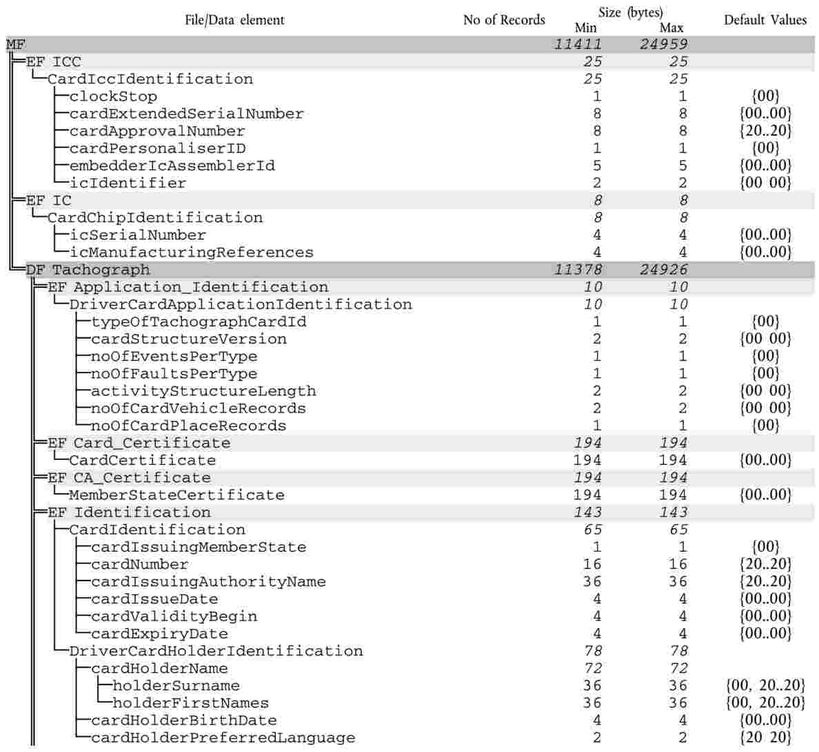

TCS_404
The following values, used to provide sizes in the table above, are the minimum and maximum record number values the driver card data structure must use:
|
|
|
Min |
Max |
|
n1 |
NoOfEventsPerType |
6 |
12 |
|
n2 |
NoOfFaultsPerType |
12 |
24 |
|
n3 |
NoOfCardVehicleRecords |
84 |
200 |
|
n4 |
NoOfCardPlaceRecords |
84 |
112 |
|
n6 |
CardActivityLengthRange |
5 544 bytes (28 days * 93 activity changes) |
13 776 bytes (28 days * 240 activity changes) |
4.2. Workshop card structure
TCS_405
After its personalisation, the workshop card shall have the following permanent file structure and file access conditions:

TCS_406
All EFs structures shall be transparent.
TCS_407
Read with secure messaging shall be possible for all files under the DF Tachograph.
TCS_408
The workshop card shall have the following data structure:


TCS_409
The following values, used to provide sizes in the table above, are the minimum and maximum record number values the workshop card data structure must use:
|
|
|
Min |
Max |
|
n1 |
NoOfEventsPerType |
3 |
3 |
|
n2 |
NoOfFaultsPerType |
6 |
6 |
|
n3 |
NoOfCardVehicleRecords |
4 |
8 |
|
n4 |
NoOfCardPlaceRecords |
6 |
8 |
|
n6 |
CardActivityLengthRange |
88 |
255 |
|
n5 |
NoOfCalibrationRecords |
198 bytes (1 day * 93 activity changes) |
492 bytes (1 day * 240 activity changes) |
4.3. Control card structure
TCS_410
After its personalisation, the control card shall have the following permanent file structure and file access conditions:

TCS_411
All EFs structures shall be transparent.
TCS_412
Read with secure messaging shall be possible for files under the DF Tachograph.
TCS_413
The control card shall have the following data structure:

TCS_414
The following values, used to provide sizes in the table above, are the minimum and maximum record number values the control card data structure must use:
|
|
|
Min |
Max |
|
n7 |
NoOfControlActivityRecords |
230 |
520 |
4.4. Company card structure
TCS_415
After its personalisation, the company card shall have the following permanent file structure and file access conditions:

TCS_416
All EFs structures shall be transparent.
TCS_417
Read with secure messaging shall be possible for all files under the DF Tachograph.
TCS_418
The company card shall have the following data structure:
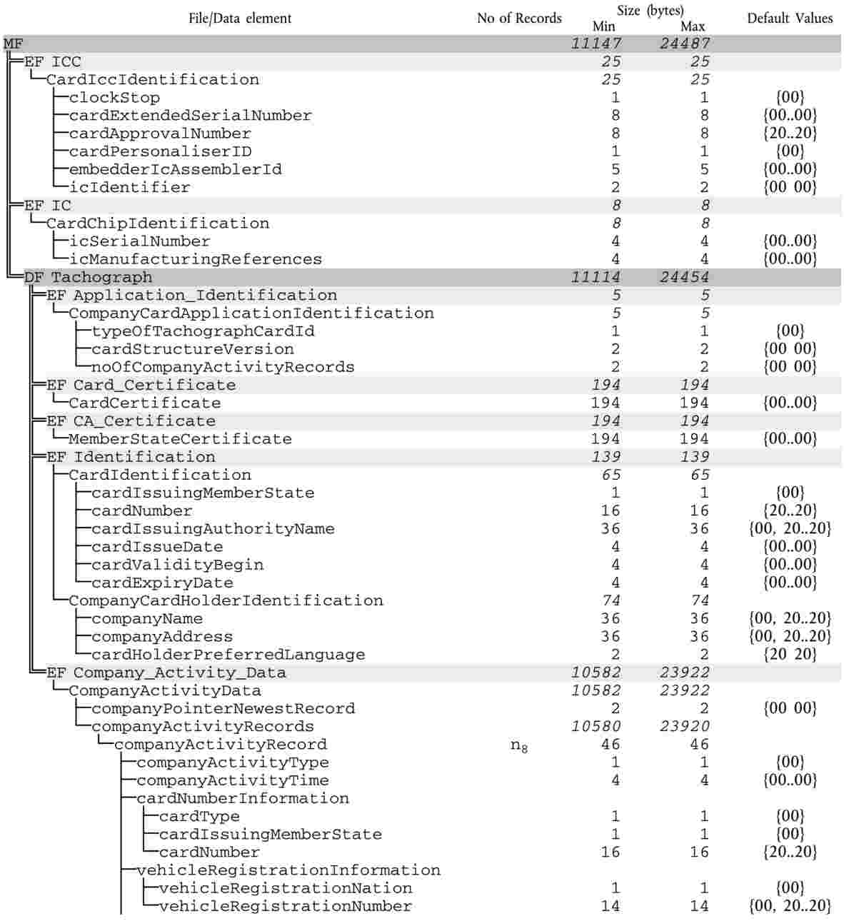
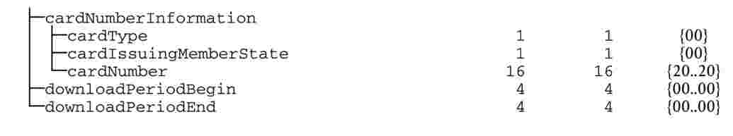
TCS_419
The following values, used to provide sizes in the table above, are the minimum and maximum record number values the company card data structure must use:
|
|
|
Min |
Max |
|
n8 |
NoOfCompanyActivityRecords |
230 |
520 |
Appendix 3
PICTOGRAMS
PIC_001
The recording equipment may use the following pictograms and pictograms combinations:
|
1. |
BASIC PICTOGRAMS
|


|
2. |
PICTOGRAM COMBINATIONS
|


Note: Additional pictogram combinations to form printout block or record identifiers are defined in Appendix 4.
Appendix 4
PRINTOUTS
CONTENTS
|
1. |
Generalities | 131 |
|
2. |
Data blocks specification | 131 |
|
3. |
Printout specifications | 137 |
|
3.1. |
Driver activities from card daily printout | 138 |
|
3.2. |
Driver activities from VU daily printout | 138 |
|
3.3. |
Events and faults from card printout | 139 |
|
3.4. |
Events and faults from VU printout | 139 |
|
3.5. |
Technical data printout | 140 |
|
3.6. |
Over speeding printout | 140 |
1. GENERALITIES
Each printout is built up by chaining various data blocks, possibly identified with a block identifier.
A data block contains one or more records, possibly identified with a record identifier.
PRT_001
When a block identifier immediately precedes a record identifier, the record identifier is not printed.
PRT_002
In the case where a data item is unknown, or must not be printed for data access rights reasons, spaces are printed instead.
PRT_003
If the content of a complete line is unknown, or need not to be printed, then the complete line is omitted.
PRT_004
Numerical data fields are printed right aligned, with a space separator for thousands and millions, and without leading zeros.
PRT_005
String data fields are printed left aligned and filled up with spaces to data item length, or truncated to data item length when needed (names and addresses).
2. DATA BLOCKS SPECIFICATION
In this chapter the following format notation conventions have been used:
|
— |
characters printed in bold denote plain text to be printed (printing remains in normal characters), |
|
— |
normal characters denote variables (pictograms or data) to be replaced by their values for printing, |
|
— |
variable names have been padded with underscores to show the data item length available for the variable, |
|
— |
dates are specified with a “dd/mm/yyyy“ (day, month, year) format. A “dd.mm.yyyy“ format may also be used, |
|
— |
the term “card identification“ denotes the composition of: the type of card through a card pictograms combination, the card issuing Member State code, a forward slash character and the card number with the replacement index and the renewal index separated with a space:
|

PRT_006
Printouts shall use the following data blocks and/or data records, in accordance with the following meanings and formats:
|
Block or record number Meaning |
|
||||||||||||
|
|
||||||||||||
|
|
||||||||||||
|
|
||||||||||||
|
|
||||||||||||
|
|
||||||||||||
|
|
||||||||||||
|
|
||||||||||||
|
|
||||||||||||
|
|
||||||||||||
|
|
||||||||||||
|
|
||||||||||||
|
|
||||||||||||
|
|
||||||||||||
|
|
||||||||||||
|
|
||||||||||||
|
|
||||||||||||
|
|
||||||||||||
|
|
||||||||||||
|
|
||||||||||||
|
|
||||||||||||
|
|
||||||||||||
|
|
||||||||||||
|
|
||||||||||||
|
|
||||||||||||
|
|
||||||||||||
|
|
||||||||||||
|
|
||||||||||||
|
|
||||||||||||
|
|
||||||||||||
|
|
||||||||||||
|
|
||||||||||||
|
|
||||||||||||
|
|
||||||||||||
|
|
||||||||||||
|
|
||||||||||||
|
|
||||||||||||
|
|
||||||||||||
|
|
||||||||||||
|
|
||||||||||||
|
|
||||||||||||
|
|
||||||||||||
|
|
||||||||||||
|
|
||||||||||||
|
|
||||||||||||
|
|
||||||||||||
|
|
||||||||||||
|
|
||||||||||||
|
|
||||||||||||
|
|
||||||||||||
|
|
||||||||||||
|
|
||||||||||||
|
|
||||||||||||
|
|
||||||||||||
|
|


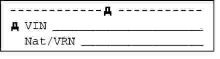

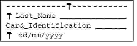
 : VU downloading,
 : printing,
 : Displaying.

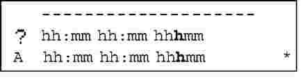


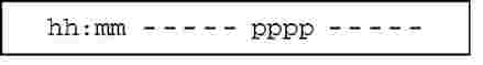


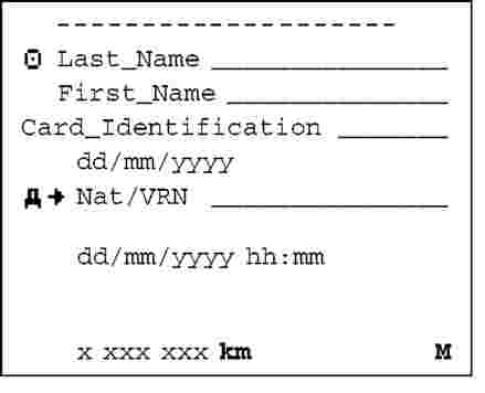


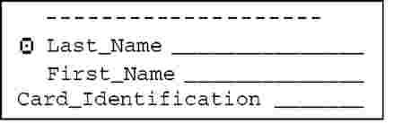

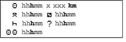

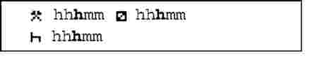


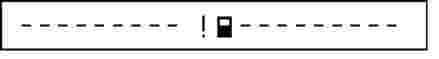

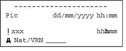
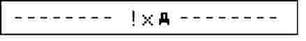


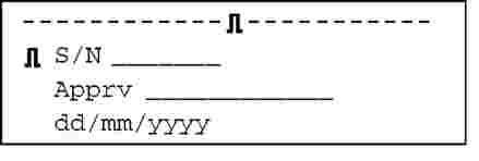


3. PRINTOUT SPECIFICATIONS
In this chapter the following notation conventions have been used:
|
|
Print block or record number N |
|
|
Print block or record number N repeated as many times as necessary |
|
|
Print blocks or records X and/or Y as needed, and repeating as many times as necessary |
3.1. Driver activities from card daily printout
PRT_007
The driver activities from card daily printout shall be in accordance with the following format:
|
|
Date and time at which the document is printed |
|
|
Type of printout |
|
|
Controller identification (if a control card is inserted in the VU) |
|
|
Driver identification (from card subject of the printout) |
|
|
Vehicle identification (vehicle from which printout is taken) |
|
|
VU identification (VU from which printout is taken) |
|
|
Last calibration of this VU |
|
|
Last control the inspected driver has been subject to |
|
|
Driver activities delimiter |
|
|
Activities of the driver in order of occurrence |
|
|
Daily summary delimiter |
|
|
Places entered in chronological order |
|
|
Activity totals |
|
|
Events or faults from card delimiter |
|
|
Event/Fault records (Last 5 events or faults stored in the card) |
|
|
Events or faults from VU delimiter |
|
|
Event/Fault records (Last 5 events or faults stored or on-going in the VU) |
|
|
Control place |
|
|
Controller's signature |
|
|
Driver's signature |


3.2. Driver activities from VU daily printout
PRT_008
The driver activities from VU daily printout shall be in accordance with the following format:
|
|
Date and time at which the document is printed |
|
|
|
Type of printout |
|
|
|
Card holder identification (for all cards inserted in VU) |
|
|
|
Vehicle identification (vehicle from which printout is taken) |
|
|
|
VU identification (VU from which printout is taken) |
|
|
|
Last calibration of this VU |
|
|
|
Last control on this recording equipment |
|
|
|
Driver activities delimiter |
|
|
|
Driver slot delimiter (slot 1) |
|
|
|
Activities in chronological order (driver slot) |
|
|
|
Co-driver slot delimiter (slot 2) |
|
|
|
Activities in chronological order (co-driver slot) |
|
|
|
Daily summary delimiter |
|
|
|
Summary of periods without card in driver slot |
|
|
|
Places entered in chronological order |
|
|
|
Activity totals |
|
|
|
Summary of periods without card in co-driver slot |
|
|
|
Places entered in chronological order |
|
|
|
Activity totals |
|
|
|
Summary of activities for a driver both slots included |
|
|
|
Places entered by this driver in chronological order |
|
|
|
Activity totals for this driver |
|
|
|
Events faults delimiter |
|
|
|
Event/Fault records (Last 5 events or faults stored or on-going in the VU) |
|
|
|
Control place |
|
|
|
Controller's signature |
|
|
|
From time |
(space available for a driver without a card to indicate which periods are relevant to himself) |
|
|
To time |
|
|
|
Driver's signature |
|


3.3. Events and faults from card printout
PRT_009
The events and faults from card printout shall be in accordance with the following format:
|
|
Date and time at which the document is printed |
|
|
Type of printout |
|
|
Controller identification (if a control card is inserted in the VU) |
|
|
Driver identification (from card subject of the printout) |
|
|
Vehicle identification (vehicle from which printout is taken) |
|
|
Events delimiter |
|
|
Event records (all events stored on the card) |
|
|
Faults delimiter |
|
|
Fault records (all faults stored on the card) |
|
|
Control place |
|
|
Controller's signature |
|
|
Driver's signature |
3.4. Events and faults from VU printout
PRT_010
The events and faults from VU printout shall be in accordance with the following format:
|
|
Date and time at which the document is printed |
|
|
Type of printout |
|
|
Card holder identification (for all cards inserted in VU) |
|
|
Vehicle identification (vehicle from which printout is taken) |
|
|
Events delimiter |
|
|
Event records (All Events stored or on-going in the VU) |
|
|
Faults delimiter |
|
|
Fault records (All Faults stored or on-going in the VU) |
|
|
Control place |
|
|
Controller's signature |
|
|
Driver's signature |


3.5. Technical data printout
PRT_011
The technical data printout shall be in accordance with the following format:
|
|
Date and time at which the document is printed |
|
|
Type of printout |
|
|
Card holder identification (for all cards inserted in VU) |
|
|
Vehicle identification (vehicle from which printout is taken) |
|
|
VU identification |
|
|
Sensor identification |
|
|
Calibration data delimiter |
|
|
Calibration records (all records available in chronological order) |
|
|
Time adjustment delimiter |
|
|
Time adjustment records (all records available from time adjustment and from calibration data records) |
|
|
Most recent event and Fault recorded in the VU |

3.6. Over speeding printout
PRT_012
The over speeding printout shall be in accordance with the following format:
|
|
Date and time at which the document is printed |
|
|
Type of printout |
|
|
Card holder identification (for all cards inserted in VU) |
|
|
Vehicle identification (vehicle from which printout is taken) |
|
|
Over speeding control information |
|
|
Over speeding data identifier |
|
|
First over speeding after the last calibration |
|
|
Over speeding data identifier |
|
|
The 5 most serious over speeding events over the last 365 days |
|
|
Over speeding data identifier |
|
|
The most serious over speeding for each of the last 10 days of occurrence |
|
|
Control place |
|
|
Controller's signature |
|
|
Driver's signature. |
Appendix 5
DISPLAY
In this appendix the following format notation conventions have been used:
|
— |
characters printed in bold denote plain text to be displayed (display remains in normal character), |
|
— |
normal characters denote variables (pictograms or data) to be replaced by their values for displaying:
|
DIS_001
The recording equipment shall display data using the following formats:
|
Data |
Format |
|
Default display |
|
|
Local time |
hh:mm |
|
Mode of operation |
O |
|
Information related to the driver |
|
|
Information related to the co-driver |
|
|
Out of scope condition opened |
|
|
Warning display |
|
|
Exceeding continuous driving time |
|
|
Event or fault |
EF |
|
Other displays |
|
|
UTC date |
UTC
or
UTC
|
|
time |
hh:mm |
|
Driver's continuous driving time and cumulative break time |
|
|
Co-driver's continuous driving time and cumulative break time |
|
|
Driver's cumulated driving time for the previous and the current week |
|
|
Co-driver's cumulated driving time for the previous and the current week |
|


Appendix 6
EXTERNAL INTERFACES
CONTENT
|
1. |
Hardware | 144 |
|
1.1. |
Connector | 144 |
|
1.2. |
Contact allocation | 146 |
|
1.3. |
Block diagram | 146 |
|
2. |
Downloading Interface | 146 |
|
3. |
Calibration Interface | 147 |
1. HARDWARE
1.1. Connector
INT_001
The downloading/calibration connector shall be a six pin connector, accessible on the front panel without the need to disconnect any part of the recording equipment, and shall comply with the following drawing (all dimensions in millimetres):
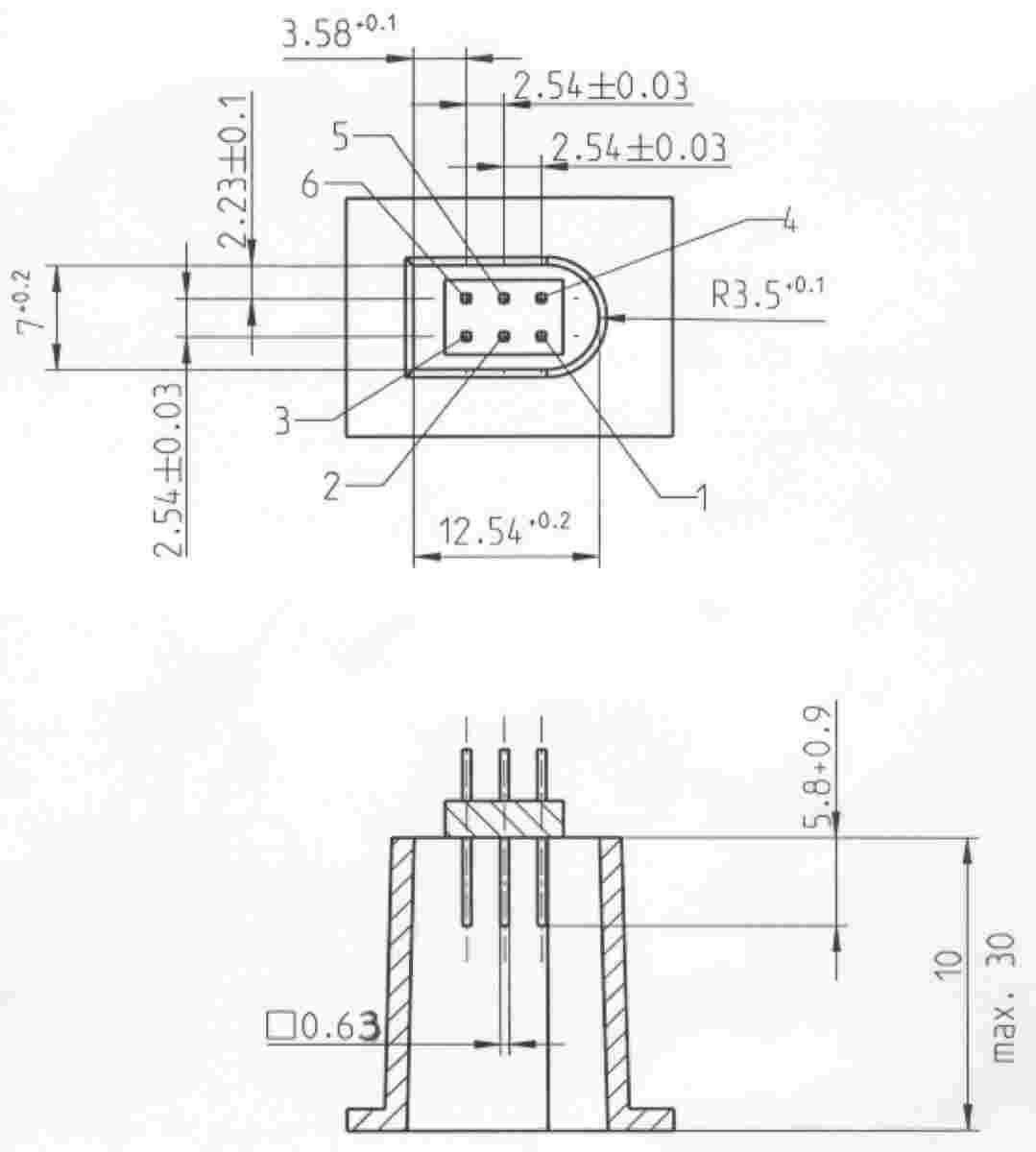
The following diagram shows a typical six pin mating plug:
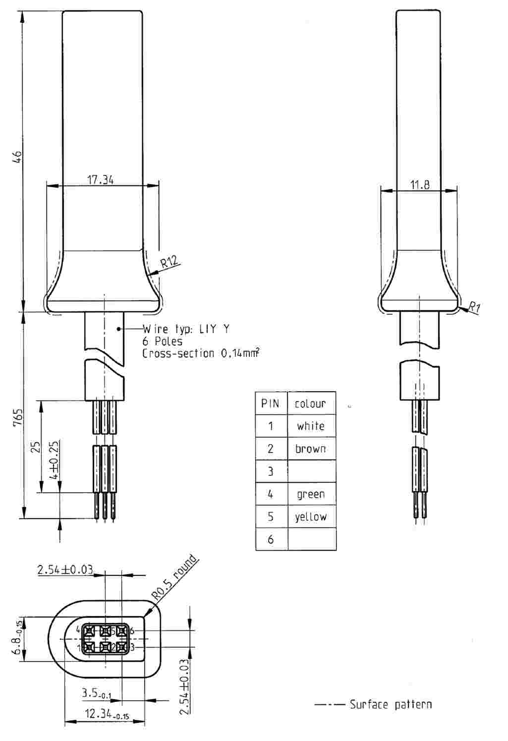
1.2. Contact allocation
INT_002
Contacts shall be allocated in accordance with the following table:
|
Pin |
Description |
Remark |
|
1 |
Battery minus |
Connected to the battery minus of the vehicle |
|
2 |
Data communication |
K-line (ISO 14 230-1) |
|
3 |
RxD — Downloading |
Data input to recording equipment |
|
4 |
Input/output signal |
Calibration |
|
5 |
Permanent power output |
The voltage range is specified to be that of the vehicle power minus 3V to allow for the voltage drop across the protective circuitry Output 40 mA |
|
6 |
TxD — Downloading |
Data output from recording equipment |
1.3. Block diagram
INT_003
The block diagram shall comply with the following:
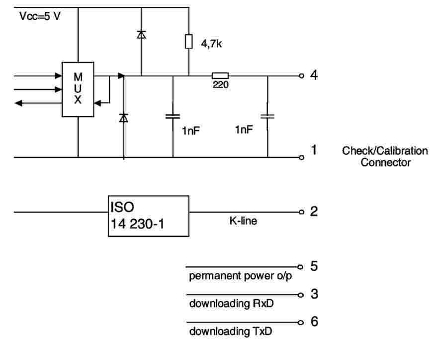
2. DOWNLOADING INTERFACE
INT_004
The downloading interface shall comply to RS232 specifications.
INT_005
The downloading interface shall use one start bit, 8 data bits LSB first, one even parity bit and 1 stop bit.

When numerical data composed by more than one byte are transmitted, the most significant byte is transmitted first and the least significant byte last.
INT_006
Transmission baud rates shall be adjustable from 9 600 bps to 115 200 bps. Transmission shall be achieved at the highest possible transmission speed, the initial baud rate after a start of communication being set at 9 600 bps.
3. CALIBRATION INTERFACE
INT_007
The data communication shall comply to ISO 14 230-1 Road vehicles — Diagnostic systems — Keyword protocol 2000 — Part 1: Physical layer, First edition: 1999.
INT_008
The input/output signal shall comply with the following electrical specification:
|
Parameter |
Minimum |
Typical |
Maximum |
Remark |
|
Ulow (in) |
|
|
1,0 V |
I = 750 μA |
|
Uhigh (in) |
4 V |
|
|
I = 200 μA |
|
Frequency |
|
|
4 kHz |
|
|
Ulow (in) |
|
|
1,0 V |
I = 1 mA |
|
Uhigh (out) |
4 V |
|
|
I = 1 mA |
INT_009
The input/output signal shall comply with the following timing diagrams:
|
Sensor signal (out) |
|
|
Test signal (in) |
|
|
UTC clock signal (out) |
|


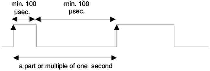
Appendix 7
DATA DOWNLOADING PROTOCOLS
CONTENTS
|
1. |
Introduction | 150 |
|
1.1. |
Scope | 150 |
|
1.2. |
Acronysmus and notations | 150 |
|
2. |
VU data downloading | 151 |
|
2.1. |
Download procedure | 151 |
|
2.2. |
Data download protocol | 151 |
|
2.2.1. |
Message structure | 151 |
|
2.2.2. |
Message types | 152 |
|
2.2.2.1. |
Start communication request (SID 81) | 154 |
|
2.2.2.2. |
Positive response start communication (SID C1) | 154 |
|
2.2.2.3. |
Start diagnostic session request (SID 10) | 154 |
|
2.2.2.4. |
Positive response start diagnostic (SID 50) | 154 |
|
2.2.2.5. |
Link control service (SID 87) | 154 |
|
2.2.2.6. |
Link control positive response (SID C7) | 154 |
|
2.2.2.7. |
Request upload (SID 35) | 154 |
|
2.2.2.8. |
Positive response request upload (SID 75) | 154 |
|
2.2.2.9. |
Transfer data request (SID 36) | 154 |
|
2.2.2.10. |
Positive response transfer data (SID 76) | 155 |
|
2.2.2.11. |
Transfer exit request (SID 37) | 155 |
|
2.2.2.12. |
Positive response request transfer exit (SID 77) | 155 |
|
2.2.2.13. |
Stop communication request (SID 82) | 155 |
|
2.2.2.14. |
Positive response stop communication (SID C2) | 155 |
|
2.2.2.15. |
Acknowledge sub message (SID 83) | 155 |
|
2.2.2.16. |
Negative response (SID 7F) | 155 |
|
2.2.3. |
Message flow | 156 |
|
2.2.4. |
Timing | 157 |
|
2.2.5. |
Error handling | 157 |
|
2.2.5.1. |
Start communication phase | 157 |
|
2.2.5.2. |
Communication phase | 157 |
|
2.2.6. |
Response message content | 160 |
|
2.2.6.1. |
Positive response transfer data overview | 160 |
|
2.2.6.2. |
Positive response transfer data activities | 161 |
|
2.2.6.3. |
Positive response transfer data events and faults | 162 |
|
2.2.6.4. |
Positive response transfer data detailed speed | 163 |
|
2.2.6.5. |
Positive response transfer data technical data | 163 |
|
2.3. |
ESM file storage | 164 |
|
3. |
Tachograph cards downloading protocol | 164 |
|
3.1. |
Scope | 164 |
|
3.2. |
Definitions | 164 |
|
3.3. |
Card downloading | 164 |
|
3.3.1. |
Initialisation sequence | 165 |
|
3.3.2. |
Sequence for un-signed data files | 165 |
|
3.3.3. |
Sequence for signed data files | 165 |
|
3.3.4. |
Sequence for resetting the calibration counter | 166 |
|
3.4. |
Data storage format | 166 |
|
3.4.1. |
Introduction | 166 |
|
3.4.2. |
File format | 166 |
|
4. |
Downloading a tachograph card via a vehicle unit | 167 |
1. INTRODUCTION
This appendix specifies the procedures to follow in order to perform the different types of data download to an external storage medium, together with the protocols that must be implemented to assure the correct data transfer and the full compatibility of the downloaded data format to allow any controller to inspect these data and be able to control their authenticity and their integrity before analysing them.
1.1. Scope
Data may be downloaded to an ESM:
|
— |
from a vehicle unit by an intelligent dedicated equipment (IDE) connected to the VU, |
|
— |
from a tachograph card by an IDE fitted with a card interface device (IFD), |
|
— |
from a tachograph card via a vehicle unit by an IDE connected to the VU. |
To give the possibility to verify the authenticity and integrity of downloaded data stored on an ESM, data is downloaded with a signature appended in accordance with Appendix 11 Common Security Mechanisms. The source equipment (VU or card) identification and its security certificates (Member State and equipment) are also downloaded. The verifier of the data must possess independently a trusted European public key.
DDP_001
Data downloaded during one download session must be stored in the ESM within one file.
1.2. Acronyms and notations
The following acronyms are used in this appendix:
|
AID |
application identifier |
|
ATR |
answer to reset |
|
CS |
checksum byte |
|
DF |
dedicated file |
|
DS_ |
diagnostic session |
|
EF |
elementary file |
|
ESM |
external storage medium |
|
FID |
file identifier (File ID) |
|
FMT |
format byte (first byte of message header) |
|
ICC |
integrated circuit card |
|
IDE |
intelligent dedicated equipment: The equipment used to perform data downloading to the ESM (e.g. personal computer) |
|
IFD |
interface device |
|
KWP |
keyword protocol 2000 |
|
LEN |
length byte (last byte of message header) |
|
PPS |
protocol parameter selection |
|
PSO |
perform security operation |
|
SID |
service identifier |
|
SRC |
source byte |
|
TGT |
target byte |
|
TLV |
tag length value |
|
TREP |
transfer response parameter |
|
TRTP |
transfer request parameter |
|
VU |
vehicle unit. |
2. VU DATA DOWNLOADING
2.1. Download procedure
In order to carry on a VU data download, the operator must perform the following operations:
|
— |
insert his tachograph card inside a card slot of the VU (16), |
|
— |
connect the IDE to the VU download connector, |
|
— |
establish the connection between the IDE and the VU, |
|
— |
select on the IDE the data to download and send the request to the VU, |
|
— |
close the download session. |
2.2. Data download protocol
The protocol is structured on a master-slave basis, with the IDE playing the master role and the VU playing the slave role.
The message structure, types and flow are principally based on the Keyword Protocol 2000 (KWP) (ISO 14230-2 Road vehicles — Diagnostic systems — Keyword protocol 2000 — Part 2: Data link layer).
The application layer is principally based on the current draft to date of ISO 14229-1 (Road vehicles — Diagnostic systems — Part 1: Diagnostic services, version 6 of 22 February 2001).
2.2.1. Message structure
DDP_002
All the messages exchanged between the IDE and the VU are formatted with a structure consisting of three parts:
|
— |
header composed by a format byte (FMT), a target byte (TGT), a source byte (SRC) and possibly a length byte (LEN), |
|
— |
data field composed by a service identifier byte (SID) and a variable number of data bytes, which can include an optional diagnostic session byte (DS_) or an optional transfer parameter byte (TRTP or TREP). |
|
— |
checksum composed by a checksum byte (CS). |
|
Header |
Data field |
Checksum |
|||||||
|
FMT |
TGT |
SRC |
LEN |
SID |
DATA |
... |
... |
... |
CS |
|
4 bytes |
Max 225 bytes |
1 byte |
|||||||
The TGT and SRC byte represent the physical address of the recipient and originator of the message. Values are F0 Hex for the IDE and EE Hex for the VU.
The LEN byte is the length of the data field part.
The checksum byte is the 8 bit sum series modulo 256 of all the bytes of the message excluding the CS itself.
FMT, SID, DS_, TRTP and TREP bytes are defined later in this document.
DDP_003
In the case where the data to be carried by the message is longer than the space available in the data field part, the message is actually sent in several submessages. Each submessage bears a header, the same SID, TREP and a 2-byte submessage counter indicating the submessage number within the total message. To enable error checking and abort the IDE acknowledges every submessage. The IDE can accept the submessage, ask for it to be re-transmitted, request the VU to start again or abort the transmission.
DDP_004
If the last submessage contains exactly 255 bytes in the data field, a final submessage with an empty (except SID TREP and submessage counter) data field must be appended to show the end of the message.
Example:
|
|
|
|||||||||
|
|
Will be transmitted as:
|
|||||||||||||||||||||||||||||||||||||||||||||||
|
|
or as:
|
||||||||||||||||||||||||||||||||||||||||||||||||||||||||||||
2.2.2. Message types
The communication protocol for data download between the VU and the IDE requires the exchange of eight different message types.
The following table summarises these messages.
|
Message Structure IDE -> <- VU |
Maximum 4 bytes Header |
Maximum 255 bytes Data |
1 byte CheckSum |
|||||||||||||||
|
FMT |
TGT |
SRC |
LEN |
SID |
DS_/TRTP |
DATA |
CS |
|||||||||||
|
Start communication request |
81 |
EE |
F0 |
|
81 |
|
|
E0 |
||||||||||
|
Positive response start communication |
80 |
F0 |
EE |
03 |
C1 |
|
8F,EA |
9B |
||||||||||
|
Start diagnostic session request |
80 |
EE |
F0 |
02 |
10 |
81 |
|
F1 |
||||||||||
|
Positive response start diagnostic |
80 |
F0 |
EE |
02 |
50 |
81 |
|
31 |
||||||||||
|
Link control service |
|
|||||||||||||||||
|
Verify Baud rate (stage 1) |
||||||||||||||||||
|
9 600Bd |
80 |
EE |
F0 |
04 |
87 |
|
01,01,01 |
EC |
||||||||||
|
19 200Bd |
80 |
EE |
F0 |
04 |
87 |
|
01,01,02 |
ED |
||||||||||
|
38 400Bd |
80 |
EE |
F0 |
04 |
87 |
|
01,01,03 |
ED |
||||||||||
|
57 600Bd |
80 |
EE |
F0 |
04 |
87 |
|
01,01,04 |
EF |
||||||||||
|
115 200Bd |
80 |
EE |
F0 |
04 |
87 |
|
01,01,05 |
F0 |
||||||||||
|
Positive response verify Baud rate |
80 |
F0 |
EE |
02 |
C7 |
|
01 |
28 |
||||||||||
|
Transition baud rate (stage 2) |
80 |
EE |
F0 |
03 |
87 |
|
02,03 |
ED |
||||||||||
|
Request Upload |
80 |
EE |
F0 |
0A |
35 |
|
00,00,00,00,00,FF,FF,FF,FF |
99 |
||||||||||
|
Positive response request upload |
80 |
F0 |
EE |
03 |
75 |
|
00,FF |
D5 |
||||||||||
|
Transfer data request |
|
|||||||||||||||||
|
Overview |
80 |
F0 |
EE |
02 |
36 |
01 |
|
97 |
||||||||||
|
Activities |
80 |
EE |
F0 |
06 |
36 |
02 |
Date |
CS |
||||||||||
|
Events and faults |
80 |
EE |
02 |
F0 |
36 |
03 |
|
99 |
||||||||||
|
Detailed speed |
80 |
EE |
F0 |
02 |
36 |
04 |
|
9A |
||||||||||
|
Technical data |
80 |
EE |
F0 |
02 |
36 |
05 |
|
9B |
||||||||||
|
Card download |
80 |
EE |
F0 |
02 |
36 |
06 |
|
9C |
||||||||||
|
Positive response transfer data |
80 |
F0 |
EE |
Len |
76 |
TREP |
Data |
CS |
||||||||||
|
Request transfer exit |
80 |
EE |
F0 |
01 |
37 |
|
|
96 |
||||||||||
|
Positive response request transfer exit |
80 |
F0 |
EE |
01 |
77 |
|
|
D6 |
||||||||||
|
Stop communication request |
80 |
EE |
F0 |
01 |
82 |
|
|
E1 |
||||||||||
|
Positive response stop communication |
80 |
F0 |
EE |
01 |
C2 |
|
|
21 |
||||||||||
|
Acknowledge sub message |
80 |
EE |
F0 |
Len |
83 |
|
Data |
CS |
||||||||||
|
Negative responses |
|
|||||||||||||||||
|
General reject |
80 |
F0 |
EE |
03 |
7F |
Sid Req |
10 |
CS |
||||||||||
|
Service not supported |
80 |
F0 |
EE |
03 |
7F |
Sid Req |
11 |
CS |
||||||||||
|
Subfunction not supported |
80 |
F0 |
EE |
03 |
7F |
Sid Req |
12 |
CS |
||||||||||
|
Incorrect message length |
80 |
F0 |
EE |
03 |
7F |
Sid Req |
13 |
CS |
||||||||||
|
Conditions not correct or request sequence error |
80 |
F0 |
EE |
03 |
7F |
Sid Req |
22 |
CS |
||||||||||
|
Request out of range |
80 |
F0 |
EE |
03 |
7F |
Sid Req |
31 |
CS |
||||||||||
|
Upload not accepted |
80 |
F0 |
EE |
03 |
7F |
Sid Req |
50 |
CS |
||||||||||
|
Response pending |
80 |
F0 |
EE |
03 |
7F |
Sid Req |
78 |
CS |
||||||||||
|
Data not available |
80 |
F0 |
EE |
03 |
7F |
Sid Req |
FA |
CS |
||||||||||
|
Notes:
|
||||||||||||||||||
2.2.2.1. Start communication request (SID 81)
DDP_005
This message is issued by the IDE to establish the communication link with the VU. Initial communications are always performed at 9 600 baud (until baud rate is eventually changed using the appropriate Link control services).
2.2.2.2. Positive response start communication (SID C1)
DDP_006
This message is issued by the VU to answer positively to a start communication request. It includes the 2 key bytes ′8F′ ′EA′ indicating that the unit supports protocol with header including target source and length information.
2.2.2.3. Start diagnostic session request (SID 10)
DDP_007
The start diagnostic session request message is issued by the IDE in order to request a new diagnostic session with the VU. The sub function 'default session' (81 Hex) indicates a standard diagnostic session is to be opened.
2.2.2.4. Positive response start diagnostic (SID 50)
DDP_008
The positive response start diagnostic message is sent by the VU to answer positively to Diagnostic Session Request.
2.2.2.5. Link control service (SID 87)
DDP_052
The link control service is used by the IDE to initiate a change in baud rate. This takes place in two steps. In step one the IDE proposes the baud rate change, indicating the new rate. On receipt of a positive message from the VU the IDE sends out confirmation of the baud rate change to the VU (step two). The IDE then changes to the new baud rate. After receipt of the confirmation the VU changes to the new baud rate
2.2.2.6. Link control positive response (SID C7)
DDP_053
The link control positive response is issued by the VU to answer positively to Link Control Service request (step one). Note that no response is given to the confirmation request (step two).
2.2.2.7. Request upload (SID 35)
DDP_009
The request upload message is issued by the IDE to specify to the VU that a download operation is requested. To meet the requirements of ISO14229 data is included covering address, the size and format details for the data requested. As these are not known to the IDE prior to a download, the memory address is set to 0, format is unencrypted and uncompressed and the memory size is set to the maximum.
2.2.2.8. Positive response request upload (SID 75)
DDP_010
The positive response request upload message is sent by the VU to indicate to the IDE that the VU is ready to download data. To meet the requirements of ISO 14229 data is included in this positive response message, indicating to the IDE that further positive response transfer data messages will include 00FF hex bytes maximum.
2.2.2.9. Transfer data request (SID 36)
DDP_011
The transfer data request is sent by the IDE to specify to the VU the type of data that are to be downloaded. A one byte transfer request parameter (TRTP) indicates the type of transfer.
There are six types of data transfer:
|
— |
overview (TRTP 01), |
|
— |
activities of a specified date (TRTP 02), |
|
— |
events and faults (TRTP 03), |
|
— |
detailed speed (TRTP 04), |
|
— |
technical data (TRTP 05), |
|
— |
card download (TRTP 06). |
DDP_054
It is mandatory for the IDE to request the overview data transfer (TRTP 01) during a download session as this only will ensure that the VU certificates are recorded within the downloaded file (and allow for verification of digital signature).
In the second case (TRTP 02) the transfer data request message includes the indication of the calendar day TimeReal format) to be downloaded.
2.2.2.10. Positive response transfer data (SID 76)
DDP_012
The positive response transfer data is sent by the VU in response to the transfer data request. The message contains the requested data, with a transfer response parameter (TREP) corresponding to the TRTP of the request.
DDP_055
In the first case (TREP 01), the VU will send data helping the IDE operator to choose the data he wants to download further. The information contained within this message is:
|
— |
security certificates, |
|
— |
vehicle identification, |
|
— |
VU current date and time, |
|
— |
minimum and maximum downloadable date (VU data), |
|
— |
indication of cards presence in the VU, |
|
— |
previous download to a company, |
|
— |
company locks, |
|
— |
previous controls. |
2.2.2.11. Request transfer exit (SID 37)
DDP_013
The request transfer exit message is sent by the IDE to inform the VU that the download session is terminated.
2.2.2.12. Positive response request transfer exit (SID 77)
DDP_014
The positive response request transfer exit message is sent by the VU to acknowledge the Request Transfer Exit.
2.2.2.13. Stop communication request (SID 82)
DDP_015
The stop communication request message is sent by the IDE to disconnect the communication link with the VU.
2.2.2.14. Positive response stop communication (SID C2)
DDP_016
The positive response stop communication message is sent by the VU to acknowledge the stop communication request.
2.2.2.15. Acknowledge submessage (SID 83)
DDP_017
The acknowledge sub message is sent by the IDE to confirm receipt of each part of a message that is being transmitted as several submessages. The data field contains the SID received from the VU and a 2-byte code as follows:
|
— |
MsgC +1 Acknowledges correct receipt of submessage number MsgC. Request from the IDE to the VU to send next submessage, |
|
— |
MsgC indicates a problem with the receipt of submessage number MsgC. Request from the IDE to the VU to send the submessage again, |
|
— |
FFFF requests termination of the message. This can be used by the IDE to end the transmission of the VU message for any reason. |
The last submessage of a message (LEN byte < 255) may be acknowledged using any of these codes or not acknowledged.
The VU responses that will consist of several sub messages are:
|
— |
positive response transfer Data (SID 76) |
2.2.2.16. Negative Response (SID 7F)
DDP_018
The negative response message is sent by the VU in response to the above request messages when the VU cannot satisfy the request. The data fields of the message contains the SID of the response (7F), the SID of the request, and a code specifying the reason of the negative response. The following codes are available:
|
— |
10 general reject The action cannot be performed for a reason not covered below |
|
— |
11 service not supported The SID of the request is not understood |
|
— |
12 sub function not supported The DS_ or TRTP of the request is not understood, or there are no further sub messages to be transmitted |
|
— |
13 incorrect message length The length of the received message is wrong |
|
— |
22 conditions not correct or request sequence error The required service is not active or the sequence of request messages is not correct |
|
— |
31 request out of range The request parameter record (data field) is not valid |
|
— |
50 upload not accepted The request cannot be performed (VU in a non appropriate mode of operation or internal fault of the VU) |
|
— |
78 response pending The action requested cannot be completed in time and the VU is not ready to accept another request |
|
— |
FA data not available The data object of a data transfer request are not available in the VU (e.g. no card is inserted, ) |
2.2.3. Message flow
A typical message flow during a normal data download procedure is the following:
|
IDE |
|
FE |
|
Start communication request |
|
|
|
|
|
Positive response |
|
Start diagnostic service request |
|
|
|
|
|
Positive response |
|
Request upload |
|
|
|
|
|
Positive response |
|
Transfer data request overview |
|
|
|
|
|
Positive response transfer |
|
Data request #2 |
|
|
|
|
|
Positive response #1 |
|
Acknowledge submessage #1 |
|
|
|
|
|
Positive response #2 |
|
Acknowledge submessage #2 |
|
|
|
|
|
Positive response #m |
|
Acknowledge submessage #m |
|
|
|
|
|
Positive response (Data field < 255 Bytes) |
|
Acknowledge submessage (optional) |
|
|
|
... |
||
|
Transfer data request #n |
|
|
|
|
|
Positive response |
|
Request transfer exit |
|
|
|
|
|
Positive response |
|
Stop communication request |
|
|
|
|
|
Positive response |
2.2.4. Timing
DDP_019
During normal operation the timing parameters shown in the following figure are relevant:

Where:
|
P1 |
= |
Inter byte time for VU response. |
|
P2 |
= |
Time between end of IDE request and start of VU response, or between end of IDE acknowledge and start of next VU response. |
|
P3 |
= |
Time between end of VU response and start of new IDE request, or between end of VU response and start of IDE acknowledge, or between end of IDE request and start of new IDE request if VU fails to respond. |
|
P4 |
= |
Inter byte time for IDE request. |
|
P5 |
= |
Extended value of P3 for card downloading. |
The allowed values for the timing parameters are showed in the following table (KWP extended timing parameters set, used in case of physical addressing for faster communication).
|
Timing Parameter |
Lower limit Value (ms) |
Upper limit value (ms) |
|
P1 |
0 |
20 |
|
P2 |
20 |
1 000 (17) |
|
P3 |
10 |
5 000 |
|
P4 |
5 |
20 |
|
P5 |
10 |
20 minutes |
2.2.5. Error handling
If an error occurs during the message exchange, the message flow scheme is modified depending on which equipment has detected the error and on the message generating the error.
In Figure 2 and Figure 3 the error handling procedures for the VU and the IDE are respectively shown.
2.2.5.1. Start communication phase
DDP_020
If the IDE detects an error during the Start Communication phase, either by timing or by the bit stream, then it will wait for a period P3 min before issuing again the request.
DDP_021
If the VU detects an error in the sequence coming from the IDE, it shall send no response and wait for another Start Communication Request message within a period P3 max.
2.2.5.2. Communication phase
Two different error handling areas can be defined:
|
1. |
The VU detects an IDE transmission error. DDP_022 DDP_023 DDP_024 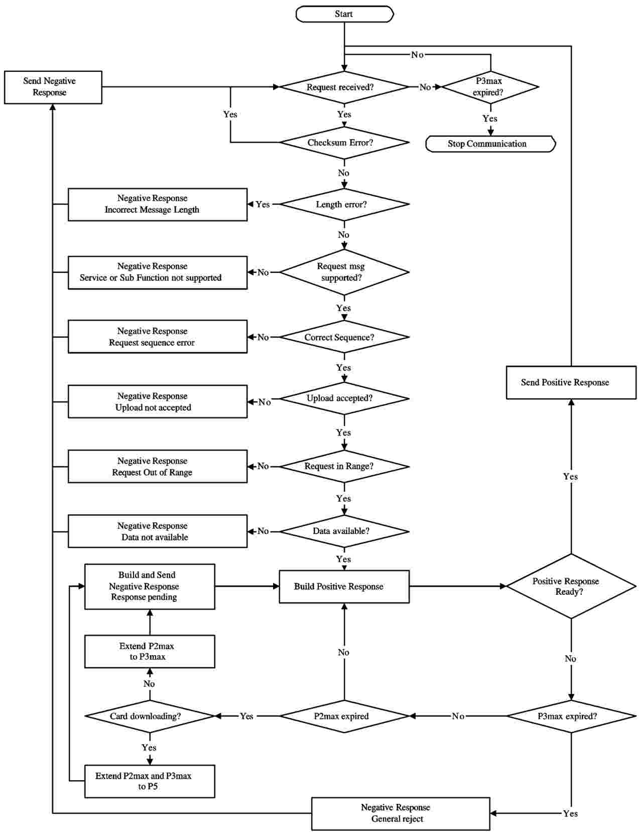
|
|
2. |
The IDE detects a VU transmission error. DDP_025 DDP_026 DDP_027 DDP_028 
|
2.2.6. Response message content
This paragraph specifies the content of the data fields of the various positive response messages.
Data elements are defined in Appendix 1 data dictionary.
2.2.6.1. Positive response transfer data overview
DDP_029
The data field of the “positive response transfer data overview“ message shall provide the following data in the following order under the SID 76 Hex, the TREP 01 Hex and appropriate sub message splitting and counting:
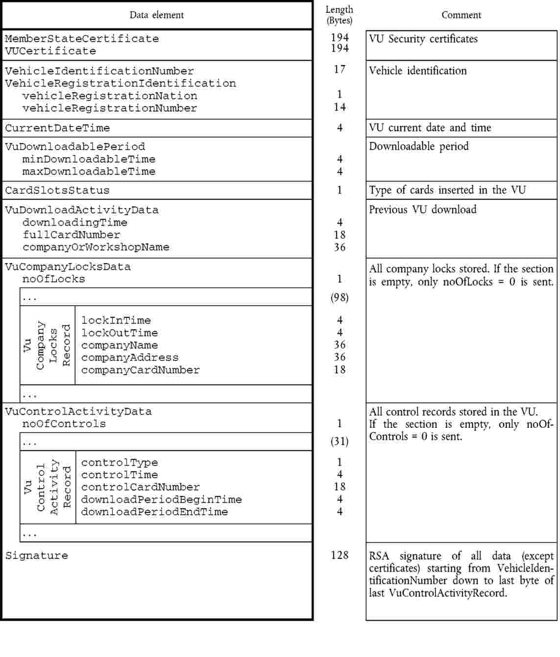
2.2.6.2. Positive response transfer data activities
DDP_030
The data field of the “positive response transfer data activities“ message shall provide the following data in the following order under the SID 76 Hex, the TREP 02 Hex and appropriate sub message splitting and counting:

2.2.6.3. Positive response transfer data events and faults
DDP_031
The data field of the “positive response transfer data events and faults“ message shall provide the following data in the following order under the SID 76 Hex, the TREP 03 Hex and appropriate sub message splitting and counting:

2.2.6.4. Positive response transfer data detailed speed
DDP_032
The data field of the “positive response transfer data detailed speed“ message shall provide the following data in the following order under the SID 76 Hex, the TREP 04 Hex and appropriate sub message splitting and countering:

2.2.6.5. Positive response transfer data technical data
DDP_033
The data field of the “positive response transfer data technical data“ message shall provide the following data in the following order under the SID 76 Hex, the TREP 05 Hex and appropriate sub message splitting and counting:
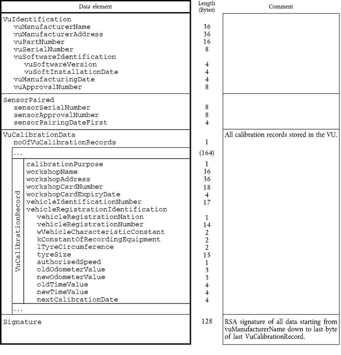
2.3. ESM File storage
DDP_034
When a download session has included a VU data transfer, the IDE shall store within one physical file all data received from the VU during the download session within positive response transfer data messages. Data stored excludes message headers, sub-message counters, empty sub-messages and checksums but include the SID and TREP (of the first sub-message only if several sub-messages).
3. TACHOGRAPH CARDS DOWNLOADING PROTOCOL
3.1. Scope
This paragraph describes the direct card data downloading of a tachograph card to an IDE. The IDE is not part of the secure environment; therefore no authentication between the card and the IDE is performed.
3.2. Definitions
Download session : Each time a download of the ICC data is performed. The session covers the complete procedure from the reset of the ICC by an IFD until the deactivation of the ICC (withdraw of the card or next reset).
Signed data file : A file from the ICC. The file is transferred to the IFD in plain text. On the ICC the file is hashed and signed and the signature is transferred to the IFD.
3.3. Card downloading
DDP_035
The download of a tachograph card includes the following steps:
|
— |
download the common information of the card in the EFs ICC and IC. This information is optional and is not secured with a digital signature, |
|
— |
Download the EFs Card_Certificate and CA_Certificate. This information is not secured with a digital signature, It is mandatory to download these files for each download session. |
|
— |
download the other application data EFs (within Tachograph DF) except EF Card_Download. This information is secured with a digital signature,
|
|
— |
When downloading a driver card, update the LastCardDownload date in EF Card_Download, |
|
— |
When downloading a workshop card, reset the calibration counter in EF Card_Download. |
3.3.1. Initialisation sequence
DDP_036
The IDE shall initiate the sequence as follows:
|
Card |
Direction |
IDE/IFD |
Meaning/Remarks |
|
|
|
Hardware reset |
|
|
ATR |
|
|
|
It is optional to use PPS to switch to a higher baudrate as long as the ICC supports it.
3.3.2. Sequence for unsigned data files
DDP_037
The sequence to download the ICC, IC, Card_Certificate and CA_Certificate is as follows:
|
Card |
Direction |
IDE/IFD |
Meaning/Remarks |
|
|
|
Select file |
Select file select by file identifiers |
|
OK |
|
|
|
|
|
|
Read Binary |
If the file contains more data than the buffer size of the reader or the card the command has to be repeated until the complete file is read. |
|
File data OK |
|
Store data to ESM |
according to 3.4, (Data storage format) |
Note: Before selecting the Card_Certificate EF, the Tachograph Application must be selected (selection by AID).
3.3.3. Sequence for signed data files
DDP_038
The following sequence shall be used for each of the following files that has to be downloaded with their signature:
|
Card |
Direction |
IDE/IFD |
Meaning/Remarks |
|
|
|
Select File |
|
|
OK |
|
|
|
|
|
|
Perform hash of File |
Calculates the hash value over the data content of the selected file using the prescribed hash algorithm in accordance with Appendix 11. This command is not an ISO-Command. |
|
Calculate hash of file and store hash value temporarily |
|
|
|
|
OK |
|
|
|
|
|
|
Read Binary |
If the file contains more data than the buffer of the reader or the card can hold, the command has to be repeated until the complete file is read. |
|
File Data OK |
|
Store received data to ESM |
according to 3.4, (Data storage format) |
|
|
|
PSO: Compute digital signature |
|
|
Perform security operation “compute digital signature“ using the temporarily stored hash value |
|
|
|
|
Signature OK |
|
Append data to the previous stored data on the ESM |
according to 3.4, (Data storage format) |
3.3.4. Sequence for resetting the calibration counter
DDP_039
The sequence to reset the NoOfCalibrationsSinceDownload counter in the EF Card_Download in a workshop card is the following:
|
Card |
Direction |
IDE/IFD |
Meaning/Remarks |
|
|
|
Select File EF Card_Download |
Select by file identifiers |
|
OK |
|
|
|
|
|
|
Update Binary NoOfCalibrationsSinceDownload = ′00 00′ |
|
|
Resets card download number |
|
|
|
|
OK |
|
|
|
3.4. Data storage format
3.4.1. Introduction
DDP_040
The downloaded data has to be stored according to the following conditions:
|
— |
the data shall be stored transparent. This means that the order of the bytes as well as the order of the bits inside the byte that are transferred from the card has to be preserved during storage, |
|
— |
all files of the card downloaded within a download session are stored in one file on the ESM. |
3.4.2. File format
DDP_041
The file format is a concatenation of several TLV objects.
DDP_042
The tag for an EF shall be the FID plus the appendix “00“.
DDP_043
The tag of an EF's signature shall be the FID of the file plus the appendix “01“.
DDP_044
The length is a two byte value. The value defines the number of bytes in the value field. The value “FF FF“ in the length field is reserved for future use.
DDP_045
When a file is not downloaded nothing related to the file shall be stored (no tag and no zero length).
DDP_046
A signature shall be stored as the next TLV object directly after the TLV object that contains the data of the file.
|
Definition |
Meaning |
Length |
|
FID (2 Bytes) || “00“ |
Tag for EF (FID) |
3 Bytes |
|
FID (2 Bytes) || “01“ |
Tag for Signature of EF(FID) |
3 Bytes |
|
xx xx |
Length of value field |
2 Bytes |
Example of data in a download file on an ESM:
|
Tag |
Length |
Value |
|
00 02 00 |
00 11 |
Data of EF ICC |
|
C1 00 00 |
00 C2 |
Data of EF Card_Certificate |
|
|
|
|
|
05 05 00 |
0A 2E |
Data of EF Vehicles_Used |
|
05 05 01 |
00 80 |
Signature of EF Vehicles_Used |
4. DOWNLOADING A TACHOGRAPH CARD VIA A VEHICLE UNIT
DDP_047
The VU must allow for downloading the content of a driver card inserted to a connected IDE.
DDP_048
The IDE shall send a “transfer data request card download“ message to the VU to initiate this mode (see 2.2.2.9).
DDP_049
The VU shall then download the whole card, file by file, in accordance with the card downloading protocol defined in paragraph 3, and forward all data received from the card to the IDE within the appropriate TLV file format (see 3.4.2) and encapsulated within a “positive response transfer data“ message.
DDP_050
The IDE shall retrieve card data from the “positive response transfer data“ message (stripping all headers, SIDs, TREPs, submessage counters, and checksums) and store them within one physical file as described in paragraph 2.3.
DDP_051
The VU shall then, as applicable, update the Control_Activity_Data or the Card_Download file of the driver card.
Appendix 8
CALIBRATION PROTOCOL
CONTENTS
|
1. |
Introduction | 170 |
|
2. |
Terms, Definitions and References | 170 |
|
3. |
Overview of services | 170 |
|
3.1. |
Services available | 170 |
|
3.2. |
Response codes | 171 |
|
4. |
Communication Services | 171 |
|
4.1. |
StartCommunication Service | 171 |
|
4.2. |
StopCommunication Service | 173 |
|
4.2.1. |
Message description | 173 |
|
4.2.2. |
Message format | 174 |
|
4.2.3. |
Parameter Definition | 175 |
|
4.3. |
TesterPresent Service | 175 |
|
4.3.1. |
Message description | 175 |
|
4.3.2. |
Message format | 175 |
|
5. |
Management Services | 176 |
|
5.1. |
StartDiagnosticSession service | 176 |
|
5.1.1. |
Message description | 176 |
|
5.1.2. |
Message format | 177 |
|
5.1.3. |
Parameter definition | 178 |
|
5.2. |
SecurityAccess service | 178 |
|
5.2.1. |
Message description | 178 |
|
5.2.2. |
Message format — SecurityAccess — requestSeed | 179 |
|
5.2.3. |
Message format — SecurityAccess — sendKey | 180 |
|
6. |
Data Transmission Services | 181 |
|
6.1. |
DataByIdentifier service | 181 |
|
6.1.1. |
Message description | 181 |
|
6.1.2. |
Message format | 181 |
|
6.1.3. |
Parameter Definition | 182 |
|
6.2. |
WriteDataByIdentifier service | 183 |
|
6.2.1 |
Message description | 183 |
|
6.2.2. |
Message format | 183 |
|
6.2.3. |
Parameter definition | 184 |
|
7. |
Control of Test Pulses — Input/Output Control functional unit | 184 |
|
7.1. |
InputOutputControlByIdentifier service | 184 |
|
7.1.1. |
Message description | 184 |
|
7.1.2. |
Message format | 185 |
|
7.1.3. |
Parameter definition | 186 |
|
8. |
dataRecords formats | 187 |
|
8.1. |
Transmitted parameter ranges | 187 |
|
8.2. |
dataRecords formats | 188 |
1. INTRODUCTION
This appendix describes how data is exchanged between a vehicle unit and a tester via the K-line which forms part of the calibration interface described in Appendix 6. It also describes control of the input/output signal line on the calibration connector.
Establishing K-line communications is described in Section 4 “Communication Services“.
This appendix uses the idea of diagnostic “sessions“ to determine the scope of K-line control under different conditions. The default session is the “StandardDiagnosticSession“ where all data can be read from a vehicle unit but no data can be written to a vehicle unit.
Selection of the diagnostic session is described in Section 5 “Management Services“.
CPR_001
The “ECUProgrammingSession“ allows data entry into the vehicle unit. In the case of entry of calibration data (requirements 097 and 098), the vehicle unit must, in addition be in the CALIBRATION mode of operation.
Data transfer via K-line is described in Section 6 “Data Transmission Services“. Formats of data transferred are detailed in Section 8 “dataRecords formats“.
CPR_002
The “ECUAdjustmentSession“ allows the selection of the I/O mode of the calibration I/O signal line via the K-line interface. Control of the calibration I/O signal line is described in section 7 “Control of Test Pulses — Input/Output Control functional unit“.
CPR_003
Throughout this document the address of the tester is referred to as ′tt′. Although there may be preferred addresses for testers, the VU shall respond correctly to any tester address. The physical address of the VU is 0xEE.
2. TERMS, DEFINITIONS AND REFERENCES
The protocols, messages and error codes are principally based on the current draft to date of ISO 14229-1 (Road vehicles — Diagnostic systems — Part 1: Diagnostic services, version 6 of 22 February 2001).
Byte encoding and hexadecimal values are used for the service identifiers, the service requests and responses, and the standard parameters.
The term “tester“ refers to the equipment used to enter programming/calibration data into the VU.
The terms “client“ and “server“ refer to the tester and the VU respectively.
The term ECU means “Electronic Control Unit“ and refers to the VU.
References:
|
ISO 14230-2 |
: |
Road Vehicles — Diagnostic Systems — Keyword Protocol 2000- Part 2: Data Link Layer. First edition: 1999. Vehicles — Diagnostic Systems. |
3. OVERVIEW OF SERVICES
3.1. Services available
The following table provides an overview of the services that will be available in the recording equipment and are defined in this document.
CPR_004
The table indicates the services that are available in an enabled diagnostic session.
|
— |
The first column lists the services that are available, |
|
— |
the second column includes the section number in this appendix where of service is further defined, |
|
— |
the third column assigns the assigns the service identifier values for request messages, |
|
— |
the fourth column specifies the services of the “StandardDiagnosticSession“ (SD) which must be implemented in each VU, |
|
— |
the fifth column specifies the services of the “ECUAdjustmentSession“ (ECUAS) which must be implemented to allow control of the I/O signal line in the front panel calibration connector of the VU, |
|
— |
the sixth column specifies the services of the “ECUProgrammingSession“ (ECUPS) which must be implemented to allow for programming of parameters in the VU. |
Table 1
Service Identifier value summary table
|
Diagnostic Service Name |
Section No |
SId Req.Value |
Diagnostic Sessions |
||
|
SD |
ECUAS |
ECUPS |
|||
|
StartCommunication |
4.1 |
81 |
|||
|
StopCommunication |
4.2 |
82 |
|
|
|
|
TesterPresent |
4.3 |
3E |
|||
|
StartDiagnosticSession |
5.1 |
10 |
|||
|
SecurityAccess |
5.2 |
27 |
|||
|
ReadDataByIdentifier |
6.1 |
22 |
|||
|
WriteDataByIdentifier |
6.2 |
2E |
|
|
|
|
InputOutputControlByIdentifier |
7.1 |
2F |
|
|
|
3.2. Response codes
Response codes are defined for each service.
4. COMMUNICATION SERVICES
Some services are necessary to establish and maintain communication. They do not appear on the application layer. The services available are detailed in the following table:
Table 2
Communication services
|
Service name |
Description |
|
StartCommunication |
The client requests to start a communication session with a server(s) |
|
StopCommunication |
The client requests to stop the current communication session |
|
TesterPresent |
The client indicates to the server that it is still present |
CPR_005
The StartCommunication Service is used for starting a communication. In order to perform any service, communication must be initialised and the communication parameters need to be appropriate for the desired mode.
4.1. StartCommunication Service
CPR_006
Upon receiving a StartCommunication indication primitive, the VU shall check if the requested communication link can be initialised under the present conditions. Valid conditions for the initialisation of a communication link are described in document ISO 14230-2.
CPR_007
Then the VU shall perform all actions necessary to initialise the communication link and send a StartCommunication response primitive with the positive response parameters selected.
CPR_008
If a VU that is already initialised (and has entered any diagnostic session) receives a new StartCommunication request (e.g. due to error recovery in the tester) the request shall be accepted and the VU shall be re-initialised.
CPR_009
If the communication link cannot be initialised for any reason, the VU shall continue operating as it was immediately prior to the attempt to initialise the communication link.
CPR_010
The StartCommunication Request message must be physically addressed.
CPR_011
Initialising the VU for services is performed through a “fast initialisation“ method,
|
— |
there is a bus-idle time prior to any activity, |
|
— |
the tester then sends an initialisation pattern, |
|
— |
all information which is necessary to establish communication is contained in the response of the VU. |
CPR_012
After completion of the initialisation,
|
— |
all communication parameters are set to values defined in Table 4 according to the key bytes, |
|
— |
the VU is waiting for the first request of the tester, |
|
— |
the VU is in the default diagnostic mode, i.e. StandardDiagnosticSession, |
|
— |
the calibration I/O signal line is in the default state, i.e. disabled state. |
CPR_014
The data rate on the K-line shall be 10 400 Baud.
CPR_016
The fast initialisation is started by the tester transmitting a wake-up pattern (Wup) on the K-line. The pattern begins after the idle time on K-line with a low time of Tinil. The tester transmits the first bit of the StartCommunication Service after a time of Twup following the first falling edge.

CPR_017
The timing values for the fast initialisation and communications in general are detailed in the tables below. There are different possibilities for the idle time:
|
— |
first transmission after power on, Tidle = 300 ms. |
|
— |
after completion of a StopCommunication Service, Tidle = P3 min. |
|
— |
after stopping communication by time-out P3 max, Tidle = O. |
Table 3
Timing values for fast initialisation
|
Parameter |
minimum value |
maximum value |
|
|
|
|
||
|
Tinil |
25 ± 1 ms |
24 ms |
26 ms |
|
Twup |
50 ± 1 ms |
49 ms |
51 ms |
Table 4
Communication timing values
|
Timing parameter |
Parameter description |
Lower limit values (ms) |
Upper limit values (ms) |
|
minimum |
maximum |
||
|
P1 |
Inter byte time for VU response |
0 |
20 |
|
P2 |
Time between tester request and VU response or two VU responses |
25 |
250 |
|
P3 |
Time between end of VU responses and start of new tester request |
55 |
5 000 |
|
P4 |
Inter byte time for tester request |
5 |
20 |
CPR_018
The message format for fast initialisation is detailed in the following tables:
Table 5
StartCommunication request message
|
Byte # |
Parameter Name |
Hex value |
Mnemonic |
|
#1 |
Format byte — physical addressing |
81 |
FMT |
|
#2 |
Target address byte |
EE |
TGT |
|
#3 |
Source address byte |
tt |
SRC |
|
#4 |
StartCommunication Request Service |
81 |
SCR |
|
#5 |
Checksum |
00-FF |
CS |
Table 6
StartCommunication positive response message
|
Byte # |
Parameter Name |
Hex value |
Mnemonic |
|
#1 |
Format byte — physical addressing |
80 |
FMT |
|
#2 |
Target address byte |
tt |
TGT |
|
#3 |
Source address byte |
EE |
SRC |
|
#4 |
Additional length byte |
03 |
LEN |
|
#5 |
StartCommunication Positive Response Service Id |
C1 |
SCRPR |
|
#6 |
Key byte 1 |
EA |
KB1 |
|
#7 |
Key byte 2 |
8F |
KB2 |
|
#8 |
Checksum |
00-FF |
CS |
CPR_019
There is no negative response to the StartCommunication Request message, if there is no positive response message to be transmitted then the VU is not initialised, nothing is transmitted and it remains in its normal operation.
4.2. StopCommunication service
4.2.1. Message description
The purpose of this communication layer service is to terminate a communication session.
CPR_020
Upon receiving a StopCommunication indication primitive, the VU shall check if the current conditions allow to terminate this communication. In this case the VU shall perform all actions necessary to terminate this communication.
CPR_021
If it is possible to terminate the communication, the VU shall issue a StopCommunication response primitive with the Positive Response parameters selected, before the communication is terminated.
CPR_022
If the communication cannot be terminated by any reason, the VU shall issue a StopCommunication response primitive with the Negative Response parameter selected.
CPR_023
If time -out of P3max is detected by the VU, the communication shall be terminated without any response primitive being issued.
4.2.2. Message format
CPR_024
The message formats for the StopCommunication primitives are detailed in the following tables:
Table 7
StopCommunication request message
|
Byte # |
Parameter Name |
Hex value |
Mnemonic |
|
#1 |
Format byte — physical addressing |
80 |
FMT |
|
#2 |
Target address byte |
EE |
TGT |
|
#3 |
Source address byte |
tt |
SRC |
|
#4 |
Additional length byte |
01 |
LEN |
|
#5 |
StopCommunication Request Service Id |
82 |
SPR |
|
#6 |
Checksum |
00-FF |
CS |
Table 8
StopCommunication positive response message
|
Byte # |
Parameter Name |
Hex value |
Mnemonic |
|
#1 |
Format byte — physical addressing |
80 |
FMT |
|
#2 |
Target address byte |
tt |
TGT |
|
#3 |
Source address byte |
EE |
SRC |
|
#4 |
Additional length byte |
01 |
LEN |
|
#5 |
StopCommunication Positive Response Service |
C2 |
SPRPR |
|
#6 |
Checksum |
00-FF |
CS |
Table 9
StopCommunication negative response message
|
Byte # |
Parameter Name |
Hex value |
Mnemonic |
|
#1 |
Format byte — physical addressing |
80 |
FMT |
|
#2 |
Target address byte |
tt |
TGT |
|
#3 |
Source address byte |
EE |
SRC |
|
#4 |
Additional length byte |
03 |
LEN |
|
#5 |
negative Response Service Id |
7F |
NR |
|
#6 |
StopCommunication Request Service Identification |
82 |
SPR |
|
#7 |
responseCode = generalReject |
10 |
RC_GR |
|
#8 |
Checksum |
00-FF |
CS |
4.2.3. Parameter definition
This service does not require any parameter definition.
4.3. TesterPresent service
4.3.1. Message description
The TesterPresent service is used by the tester to indicate to the server that it is still present, in order to prevent the server from automatically returning to normal operation and possibly stopping the communication. This service, sent periodically, keeps the diagnostic session/communication active by resetting the P3 timer each time a request for this service is received.
4.3.2. Message format
CPR_079
The message formats for the TesterPresent primitives are detailed in the following tables.
Table 10
TesterPresent request message
|
Byte # |
Parameter Name |
Hex value |
Mnemonic |
|
#1 |
Format byte — physical addressing |
80 |
FMT |
|
#2 |
Target address byte |
EE |
TGT |
|
#3 |
Source address byte |
tt |
SRC |
|
#4 |
Additional length byte |
02 |
LEN |
|
#5 |
TesterPresent Request Service Id |
3E |
TP |
|
#6 |
Sub Function = responseRequired = [yes |
01 |
RESPREQ_Y |
|
no] |
02 |
RESPREQ_NO |
|
|
#7 |
Checksum |
00-FF |
CS |
CPR_080
If the responseRequired parameter is set to “yes“, then the server shall respond with the following positive response message. If set to “no“, then no response is sent by the server.
Table 11
TesterPresent positive response message
|
Byte # |
Parameter Name |
Hex value |
Mnemonic |
|
#1 |
Format byte — physical addressing |
80 |
FMT |
|
#2 |
Target address byte |
tt |
TGT |
|
#3 |
Source address byte |
EE |
SRC |
|
#4 |
Additional length byte |
01 |
LEN |
|
#5 |
TesterPresent Positive Response Service Id |
7E |
TPPR |
|
#6 |
Checksum |
00-FF |
CS |
CPR_081
The service shall support the following negative responses codes:
Table 12
TesterPresent negative response message
|
Byte # |
Parameter Name |
Hex value |
Mnemonic |
|
#1 |
Format byte — physical addressing |
80 |
FMT |
|
#2 |
Target address byte |
tt |
TGT |
|
#3 |
Source address byte |
EE |
SRC |
|
#4 |
Additional length byte |
03 |
LEN |
|
#5 |
negative Response Service Id |
7F |
NR |
|
#6 |
TesterPresent Request Service Identification |
3E |
TP |
|
#7 |
responseCode = [SubFunctionNotSupported-InvalidFormat |
12 |
RC_SFNS_IF |
|
incorrectMessageLength] |
13 |
RC_IML |
|
|
#8 |
Checksum |
00-FF |
CS |
5. MANAGEMENT SERVICES
The services available are detailed in the following table:
Table 13
Management services
|
Service name |
Description |
|
StartDiagnosticSession |
The client requests to start a diagnostic session with a VU |
|
SecurityAccess |
The client requests access to functions restricted to authorised users |
5.1. StartDiagnosticSession service
5.1.1. Message description
CPR_025
The service StartDiagnosticSession is used to enable different diagnostic sessions in the server. A diagnostic session enables a specific set of services according to Table 17. A session can enable vehicle manufacturer specific services which are not part of this document. Implementation rules shall conform to the following requirements:
|
— |
there shall be always exactly one diagnostic session active in the VU, |
|
— |
the VU shall always start the StandardDiagnosticSession when powered up. If no other diagnostic session is started, then the StandardDiagnosticSession shall be running as long as the VU is powered, |
|
— |
if a diagnostic session which is already running has been requested by the tester, then the VU shall send a positive response message, |
|
— |
whenever the tester requests a new diagnostic session, the VU shall first send a StartDiagnosticSession positive response message before the new session becomes active in the VU. If the VU is not able to start the requested new diagnostic session, then it shall respond with a StartDiagnosticSession negative response message, and the current session shall continue. |
CPR_026
The diagnostic session shall only be started if communication has been established between the client and the VU.
CPR_027
The timing parameters defined in Table 4 shall be active after a successful StartDiagnosticSession with the diagnosticSession parameter set to “StandardDiagnosticSession“ in the request message if another diagnostic session was previously active.
5.1.2. Message format
CPR_028
The message formats for the StartDiagnosticSession primitives are detailed in the following tables:
Table 14
StartDiagnosticSession request message
|
Byte # |
Parameter Name |
Hex value |
Mnemonic |
|
#1 |
Format byte — physical addressing |
80 |
FMT |
|
#2 |
Target address byte |
EE |
TGT |
|
#3 |
Source address byte |
tt |
SRC |
|
#4 |
Additional length byte |
02 |
LEN |
|
#5 |
StartDiagnosticSession request service Id |
10 |
STDS |
|
#6 |
diagnosticSession = (one value from Table 17) |
xx |
DS_… |
|
#7 |
Checksum |
00-FF |
CS |
Table 15
StartDiagnosticSession positive response message
|
Byte # |
Parameter Name |
Hex value |
Mnemonic |
|
#1 |
Format byte — physical addressing |
80 |
FMT |
|
#2 |
Target address byte |
tt |
TGT |
|
#3 |
Source address byte |
EE |
SRC |
|
#4 |
Additional length byte |
02 |
LEN |
|
#5 |
StartDiagnosticSession Positive Response Service Id |
50 |
STDSPR |
|
#6 |
DiagnosticSession = (same value as in byte #6 Table 14) |
xx |
DS_… |
|
#7 |
Checksum |
00-FF |
CS |
Table 16
StartDiagnosticSession negative response message
|
Byte # |
Parameter Name |
Hex value |
Mnemonic |
|
#1 |
Format byte — physical addressing |
80 |
FMT |
|
#2 |
Target address byte |
tt |
TGT |
|
#3 |
Source address byte |
EE |
SRC |
|
#4 |
Additional length byte |
03 |
LEN |
|
#5 |
Negative response service Id |
7F |
NR |
|
#6 |
StartDiagnosticSession request service Id |
10 |
STDS |
|
#7 |
ResponseCode = (subFunctionNotSupported (19) |
12 |
RC_SFNS |
|
incorrectMessageLength (20) |
13 |
RC_IML |
|
|
conditionsNotCorrect (21)) |
22 |
RC_CNC |
|
|
#8 |
Checksum |
00-FF |
CS |
5.1.3. Parameter definition
CPR_029
The parameter diagnosticSession (DS_) is used by the StartDiagnosticSession service to select the specific behaviour of the server(s). The following diagnostic sessions are specified in this document:
Table 17
Definition of diagnosticSession values
|
Hex |
Description |
Mnemonic |
|
81 |
StandardDiagnosticSession This diagnostic session enables all services specified in Table 1 column 4 “SD“. These services allow reading of data from a server (VU). This diagnostic Session is active after the initialisation has been successfully completed between client (tester) and server (VU). This diagnostic session may be overwritten by other diagnostic sessions specified in this section. |
SD |
|
85 |
ECUProgrammingSession This diagnostic session enables all services specified in Table 1 column 6 “ECUPS“. These services support the memory programming of a server (VU) This diagnostic session may be overwritten by other diagnostic sessions specified in this section. |
ECUPS |
|
87 |
ECUAdjustmentSession This diagnostic session enables all services specified in Table 1 column 5 “ECUAS“. These services support the input/output control of a server (VU). This diagnostic session may be overwritten by other diagnostic sessions specified in this section. |
ECUAS |
5.2. SecurityAccess service
Writing of calibration data or access to the calibration input/output line is not possible unless the VU is in CALIBRATION mode. In addition to insertion of a valid workshop card into the VU, it is necessary to enter the appropriate PIN into the VU before access to the CALIBRATION mode is granted.
The SecurityAccess service provides a means to enter the PIN and to indicate to the tester whether or not the VU is in CALIBRATION mode.
It is acceptable that the PIN may be entered through alternative methods.
5.2.1. Message description
The SecurityAccess service consists of a SecurityAccess “requestSeed“ message, eventually followed by a SecurityAccess “sendKey“ message. The SecurityAccess service must be carried out after the StartDiagnosticSession service.
CPR_033
The tester shall use the SecurityAccess "requestSeed" message to check if the vehicle unit is ready to accept a PIN.
CPR_034
If the vehicle unit is already in CALIBRATION mode, it shall answer the request by sending a “seed“ of 0x0000 using the service SecurityAccess Positive Response.
CPR_035
If the vehicle unit is ready to accept a PIN for verification by a workshop card, it shall answer the request by sending a “seed“ greater than 0x0000 using the service SecurityAccess positive response.
CPR_036
If the vehicle unit is not ready to accept a PIN from the tester, either because the workshop card inserted is not valid, or because no workshop card has been inserted, or because the vehicle unit expects the PIN from another method, it shall answer the request with a negative response with a response code set to conditionsNotCorrectOrRequestSequenceError.
CPR_037
The tester shall then, eventually, use the SecurityAccess “sendKey“ message to forward a PIN to the Vehicle Unit. To allow time for the card authentication process to take place, the VU shall use the negative response code requestCorrectlyReceived-ResponsePending to extend the time to respond. However, the maximum time to respond shall not exceed five minutes. As soon as the requested service has been completed, the VU shall send a positive response message or negative response message with a response code different from this one. The negative response code requestCorrectlyReceived-ResponsePending may be repeated by the VU until the requested service is completed and the final response message is sent.
CPR_038
The vehicle unit shall answer to this request using the service SecurityAccess Positive Response only when in CALIBRATION mode.
CPR_039
In the following cases, the vehicle unit shall answer to this request with a Negative Response with a response code set to:
|
— |
subFunctionNot supported: invalid format for the subfunction parameter (accessType), |
|
— |
conditionsNotCorrectOrRequestSequenceError: vehicle unit not ready to accept a PIN entry, |
|
— |
invalidKey: PIN not valid and number of PIN checks attempts not exceeded, |
|
— |
exceededNumberOfAttempts: PIN not valid and number of PIN checks attempts exceeded, |
|
— |
generalReject: Correct PIN but mutual authentication with workshop card failed. |
5.2.2. Message format — SecurityAccess — requestSeed
CPR_040
The message formats for the SecurityAccess “requestSeed“ primitives are detailed in the following tables:
Table 18
SecurityAccess request — requestSeed message
|
Byte # |
Parameter Name |
Hex value |
Mnemonic |
|
#1 |
Format byte — physical addressing |
80 |
FMT |
|
#2 |
Target address byte |
EE |
TGT |
|
#3 |
Source address byte |
tt |
SRC |
|
#4 |
Additional length byte |
02 |
LEN |
|
#5 |
SecurityAccess request service Id |
27 |
SA |
|
#6 |
accessType — requestSeed |
7D |
AT_RSD |
|
#7 |
Checksum |
00-FF |
CS |
Table 19
SecurityAccess — requestSeed positive response message
|
Byte # |
Parameter Name |
Hex value |
Mnemonic |
|
#1 |
Format byte — physical addressing |
80 |
FMT |
|
#2 |
Target address byte |
tt |
TGT |
|
#3 |
Source address byte |
EE |
SRC |
|
#4 |
Additional length byte |
04 |
LEN |
|
#5 |
SecurityAccess positive response service Id |
67 |
SAPR |
|
#6 |
accessType — requestSeed |
7D |
AT_RSD |
|
#7 |
Seed High |
00-FF |
SEEDH |
|
#8 |
Seed Low |
00-FF |
SEEDL |
|
#9 |
Checksum |
00-FF |
CS |
Table 20
SecurityAccess negative response message
|
Byte # |
Parameter Name |
Hex value |
Mnemonic |
|
#1 |
Format byte — physical addressing |
80 |
FMT |
|
#2 |
Target address byte |
tt |
TGT |
|
#3 |
Source address byte |
EE |
SRC |
|
#4 |
Additional length byte |
03 |
LEN |
|
#5 |
negativeResponse Service Id |
7F |
NR |
|
#6 |
SecurityAccess request service Id |
27 |
SA |
|
#7 |
responseCode = (conditionsNotCorrectOrRequestSequenceError |
22 |
RC_CNC |
|
incorrectMessageLength) |
13 |
RC_IML |
|
|
#8 |
Checksum |
00-FF |
CS |
5.2.3. Message format — SecurityAccess — sendKey
CPR_041
The message formats for the SecurityAccess “sendKey“ primitives are detailed in the following tables:
Table 21
SecurityAccess request — sendKey message
|
Byte # |
Parameter Name |
Hex value |
Mnemonic |
|
#1 |
Format byte — physical addressing |
80 |
FMT |
|
#2 |
Target address byte |
EE |
TGT |
|
#3 |
Source address byte |
tt |
SRC |
|
#4 |
Additional length byte |
m+2 |
LEN |
|
#5 |
SecurityAccess Request Service Id |
27 |
SA |
|
#6 |
accessType — sendKey |
7E |
AT_SK |
|
#7 to #m+6 |
Key #1 (High) |
xx |
KEY |
|
… |
… |
|
|
|
Key #m (low, m must be a minimum of 4, and a maximum of 8) |
xx |
|
|
|
#m+7 |
Checksum |
00-FF |
CS |
Table 22
SecurityAccess — sendKey positive response message
|
Byte # |
Parameter Name |
Hex value |
Mnemonic |
|
#1 |
Format byte — physical addressing |
80 |
FMT |
|
#2 |
Target address byte |
tt |
TGT |
|
#3 |
Source address byte |
EE |
SRC |
|
#4 |
Additional length byte |
02 |
LEN |
|
#5 |
SecurityAccess positive response service Id |
67 |
SAPR |
|
#6 |
accessType — sendKey |
7E |
AT_SK |
|
#7 |
Checksum |
00-FF |
CS |
Table 23
SecurityAccess negative response message
|
Byte # |
Parameter Name |
Hex value |
Mnemonic |
|
#1 |
Format byte — physical addressing |
80 |
FMT |
|
#2 |
Target address byte |
tt |
TGT |
|
#3 |
Source address byte |
EE |
SRC |
|
#4 |
Additional length byte |
03 |
LEN |
|
#5 |
NegativeResponse Service Id |
7F |
NR |
|
#6 |
SecurityAccess request service Id |
27 |
SA |
|
#7 |
ResponseCode = (generalReject |
10 |
RC_GR |
|
subFunctionNotSupported |
12 |
RC_SFNS |
|
|
incorrectMessageLength |
13 |
RC_IML |
|
|
conditionsNotCorrectOrRequestSequenceError |
22 |
RC_CNC |
|
|
invalidKey |
35 |
RC_IK |
|
|
exceededNumberOfAttempts |
36 |
RC_ENA |
|
|
requestCorrectlyReceived-ResponsePending) |
78 |
RC_RCR_RP |
|
|
#8 |
Checksum |
00-FF |
CS |
6. DATA TRANSMISSION SERVICES
The services available are detailed in the following table:
Table 24
Data transmission services
|
Service name |
Description |
|
ReadDataByIdentifier |
The client requests the transmission of the current value of a record with access by recordDataIdentifier |
|
WriteDataByIdentifier |
The client requests to write a record accessed by recordDataIdentifier |
6.1. ReadDataByIdentifier service
6.1.1. Message description
CPR_050
The ReadDataByIdentifier service is used by the client to request data record values from a server. The data are identified by a recordDataIdentifier. It is the VU manufacturer's responsibility that the server conditions are met when performing this service.
6.1.2. Message format
CPR_051
The message formats for the ReadDataByIdentifier primitives are detailed in the following tables:
Table 25
ReadDataByIdentifier request message
|
Byte # |
Parameter Name |
Hex value |
Mnemonic |
|
#1 |
Format byte — physical addressing |
80 |
FMT |
|
#2 |
Target address byte |
EE |
TGT |
|
#3 |
Source address byte |
tt |
SRC |
|
#4 |
Additional length byte |
03 |
LEN |
|
#5 |
ReadDataByIdentifier Request Service Id |
22 |
RDBI |
|
#6 and #7 |
recordDataIdentifier = (a valor from Table 28) |
xxxx |
RDI_… |
|
#8 |
Checksum |
00-FF |
CS |
Table 26
ReadDataByIdentifier positive response message
|
Byte # |
Parameter Name |
Hex value |
Mnemonic |
|
#1 |
Format byte — physical addressing |
80 |
FMT |
|
#2 |
Target address byte |
tt |
TGT |
|
#3 |
Source address byte |
EE |
SRC |
|
#4 |
Additional length byte |
m+3 |
LEN |
|
#5 |
ReadDataByIdentifier Positive Response Service Id |
62 |
RDBIPR |
|
#6 and #7 |
recordDataIdentifier = (the same value as bytes #6 and #7 Table 25) |
xxxx |
RDI_… |
|
#8 to #m+7 |
dataRecord() = (data#1 |
xx |
DREC_DATA1 |
|
: |
: |
: |
|
|
data#m) |
xx |
DREC_DATAm |
|
|
#m+8 |
Checksum |
00-FF |
CS |
Table 27
ReadDataByIdentifier negative response message
|
Byte # |
Parameter Name |
Hex value |
Mnemonic |
|
#1 |
Format byte — physical addressing |
80 |
FMT |
|
#2 |
Target address byte |
tt |
TGT |
|
#3 |
Source address byte |
EE |
SRC |
|
#4 |
Additional length byte |
03 |
LEN |
|
#5 |
NegativeResponse Service Id |
7F |
NR |
|
#6 |
ReadDataByIdentifier Request Service Id |
22 |
RDBI |
|
#7 |
ResponseCode = (requestOutOfRange |
31 |
RC_ROOR |
|
incorrectMessageLength |
13 |
RC_IML |
|
|
conditionsNotCorrect) |
22 |
RC_CNC |
|
|
#8 |
Checksum |
00-FF |
CS |
6.1.3. Parameter definition
CPR_052
The parameter recordDataIdentifier (RDI_) in the ReadDataByIdentifier request message identifies a data record.
CPR_053
recordDataIdentifier values defined by this document are shown in the table below.
The recordDataIdentifier table consists of four columns and multiple lines.
|
— |
The first column (Hex) includes the “hex value“ assigned to the recordDataIdentifier specified in the third column. |
|
— |
The second column (Data element) specifies the data element of Appendix 1 on which the recordDataIdentifier is based (transcoding is sometimes necessary). |
|
— |
The third column (Description) specifies the corresponding recordDataIdentifier name. |
|
— |
The fourth column (Mnemonic) specifies the mnemonic of this recordDataIdentifier. |
Table 28
Definition of recordDataIdentifier values
|
Hex |
Data element |
recordDataIdentifier Name (see format in Section 8.2) |
Mnemonic |
|
F90B |
CurrentDateTime |
TimeDate |
RDI_TD |
|
F912 |
HighResOdometer |
HighResolutionTotalVehicleDistance |
RDI_HRTVD |
|
F918 |
K-ConstantOfRecordingEquipment |
Kfactor |
RDI_KF |
|
F91C |
L-TyreCircumference |
LfactorTyreCircumference |
RDI_LF |
|
F91D |
W-VehicleCharacteristicConstant |
WvehicleCharacteristicFactor |
RDI_WVCF |
|
F921 |
TyreSize |
TyreSize |
RDI_TS |
|
F922 |
nextCalibrationDate |
NextCalibrationDate |
RDI_NCD |
|
F92C |
SpeedAuthorised |
SpeedAuthorised |
RDI_SA |
|
F97D |
vehicleRegistrationNation |
RegisteringMemberState |
RDI_RMS |
|
F97E |
VehicleRegistrationNumber |
VehicleRegistrationNumber |
RDI_VRN |
|
F190 |
VehicleIdentificationNumber |
VIN |
RDI_VIN |
CPR_054
The parameter dataRecord (DREC_) is used by the ReadDataByIdentifier positive response message to provide the data record value identified by the recordDataIdentifier to the client (tester). Data formats are specified in Section 8. Additional user optional dataRecords including VU specific input, internal and output data may be implemented, but are not defined in this document.
6.2. WriteDataByIdentifier service
6.2.1. Message description
CPR_056
The WriteDataByIdentifier service is used by the client to write data record values to a server. The data are identified by a recordDataIdentifier. It is the VU manufacturer's responsibility that the server conditions are met when performing this service. To update the parameters listed in Table 28 the VU must be in CALIBRATION mode.
6.2.2. Message format
CPR_057
The message formats for the WriteDataByIdentifier primitives are detailed in the following tables:
Table 29
WriteDataByIdentifier request message
|
Byte # |
Parameter Name |
Hex value |
Mnemonic |
|
#1 |
Format byte — physical addressing |
80 |
FMT |
|
#2 |
Target address byte |
EE |
TGT |
|
#3 |
Source address byte |
tt |
SRC |
|
#4 |
Additional length byte |
m+3 |
LEN |
|
#5 |
WriteDataByIdentifier request service Id |
2E |
WDBI |
|
#6 and #7 |
recordDataIdentifier = (a value from Table 28) |
xxxx |
RDI_… |
|
#8 to #m+7 |
dataRecord() = (data#1 |
xx |
DREC_DATA1 |
|
: |
: |
: |
|
|
data#m) |
xx |
DREC_DATAm |
|
|
#m+8 |
Checksum |
00-FF |
CS |
Table 30
WriteDataByIdentifier positive response message
|
Byte # |
Parameter Name |
Hex value |
Mnemonic |
|
#1 |
Format byte — physical addressing |
80 |
FMT |
|
#2 |
Target address byte |
tt |
TGT |
|
#3 |
Source address byte |
EE |
SRC |
|
#4 |
Additional length byte |
03 |
LEN |
|
#5 |
WriteDataByIdentifier positive response service Id |
6E |
WDBIPR |
|
#6 and #7 |
recordDataIdentifier = (the same value as bytes #6 and #7 Table 29) |
xxxx |
RDI_… |
|
#8 |
Checksum |
00-FF |
CS |
Table 31
WriteDataByIdentifier negative response message
|
Byte # |
Parameter Name |
Hex value |
Mnemonic |
|
#1 |
Format byte — physical addressing |
80 |
FMT |
|
#2 |
Target address byte |
tt |
TGT |
|
#3 |
Source address byte |
EE |
SRC |
|
#4 |
Additional length byte |
03 |
LEN |
|
#5 |
NegativeResponse Service Id |
7F |
NR |
|
#6 |
WriteDataByIdentifier request service Id |
2E |
WDBI |
|
#7 |
ResponseCode = (requestOutOfRange |
31 |
RC_ROOR |
|
incorrectMessageLength |
13 |
RC_IML |
|
|
conditionsNotCorrect) |
22 |
RC_CNC |
|
|
#8 |
Checksum |
00-FF |
CS |
6.2.3. Parameter definition
The parameter recordDataIdentifier (RDI_) is defined in Table 28.
The parameter dataRecord (DREC_) is used by the WriteDataByIdentifier request message to provide the data record values identified by the recordDataIdentifier to the server (VU). Data formats are specified in Section 8.
7. CONTROL OF TEST PULSES — INPUT/OUTPUT CONTROL FUNCTIONAL UNIT
The services available are detailed in the following table:
Table 32
Input/Output control functional unit
|
Service name |
Description |
|
InputOutputControlByIdentifier |
The client requests the control of an input/output specific to the server |
7.1. Message description
7.1.1. Message description
There is a connection via the front connector which allows test pulses to be controlled or monitored using a suitable tester.
CPR_058
This calibration I/O signal line can be configured by K-line command using the InputOutputControlByIdentifier service to select the required input or output function for the line. The available states of the line are:
|
— |
disabled, |
|
— |
speedSignalInput, where the calibration I/O signal line is used to input a speed signal (test signal) replacing the motion sensor speed signal, |
|
— |
realTimeSpeedSignalOutputSensor, where the calibration I/O signal line is used to output the speed signal of the motion sensor, |
|
— |
RTCOutput, where the calibration I/O signal line is used to output the UTC clock signal. |
CPR_059
The vehicle unit must have entered an adjustment session and must be in CALIBRATION mode to configure the state of the line. On exit of the adjustment session or of the CALIBRATION mode the vehicle unit must ensure the calibration I/O signal line is returned to the “disabled“ (default) state.
CPR_060
If speed pulses are received at the real time speed signal input line of the VU while the calibration I/O signal line is set to input then the calibration I/O signal line shall be set to output or returned to the disabled state.
CPR_061
The sequence shall be:
|
— |
establish communications by StartCommunication Service |
|
— |
enter an adjustment session by StartDiagnosticSession Service and be in CALIBRATION mode of operation (the order of these two operations is not important). |
|
— |
change the state of the output by InputOutputControlByIdentifier Service. |
7.1.2. Message format
CPR_062
The message formats for the InputOutputControlByIdentifier primitives are detailed in the following tables:
Table 33
InputOutputControlByIdentifier request message
|
Byte # |
Parameter name |
Hex value |
Mnemonic |
|
#1 |
Format byte — physical addressing |
80 |
FMT |
|
#2 |
Target address byte |
EE |
TGT |
|
#3 |
Source address byte |
tt |
SRC |
|
#4 |
Additional length byte |
xx |
LEN |
|
#5 |
InputOutputControlByIdentifier request Sid |
2F |
IOCBI |
|
#6 and #7 |
InputOutputIdentifier = (CalibrationInputOutput) |
F960 |
IOI_CIO |
|
#8 or #8 to #9 |
ControlOptionRecord = ( |
|
COR_… |
|
inputOutputControlParameter — one value from Table 36 |
xx |
IOCP_… |
|
|
controlState — one value from Table 38 (see note below)) |
xx |
CS_… |
|
|
#9 or #10 |
Checksum |
00-FF |
CS |
|
Note: The controlState parameter is present only in some cases (see 7.1.3). |
|||
Table 34
InputOutputControlByIdentifier positive response message
|
Byte # |
Parameter Name |
Hex value |
Mnemonic |
|
#1 |
Format byte — physical addressing |
80 |
FMT |
|
#2 |
Target address byte |
tt |
TGT |
|
#3 |
Source address byte |
EE |
SRC |
|
#4 |
Additional length byte |
xx |
LEN |
|
#5 |
inputOutputControlByIdentifier positive response SId |
6F |
IOCBIPR |
|
#6 and #7 |
inputOutputIdentifier = (CalibrationInputOutput) |
F960 |
IOI_CIO |
|
#8 or #8 to #9 |
controlStatusRecord = ( |
|
CSR_ |
|
inputOutputControlParameter (same value as byte #8 Table 33) |
xx |
IOCP_… |
|
|
controlState (same value as byte #9 Table 33)) (if applicable) |
xx |
CS_… |
|
|
#9 or #10 |
Checksum |
00-FF |
CS |
Table 35
InputOutputControlByIdentifier negative response message
|
Byte # |
Parameter Name |
Hex value |
Mnemonic |
|
#1 |
Format byte — physical addressing |
80 |
FMT |
|
#2 |
Target address byte |
tt |
TGT |
|
#3 |
Source address byte |
EE |
SRC |
|
#4 |
Additional length byte |
03 |
LEN |
|
#5 |
negativeResponse Service Id |
7F |
NR |
|
#6 |
inputOutputControlByIdentifier request SId |
2F |
IOCBI |
|
#7 |
responseCode = ( |
|
|
|
incorrectMessageLength |
13 |
RC_IML |
|
|
conditionsNotCorrect |
22 |
RC_CNC |
|
|
requestOutOfRange |
31 |
RC_ROOR |
|
|
deviceControlLimitsExceeded) |
7A |
RC_DCLE |
|
|
#8 |
Checksum |
00-FF |
CS |
7.1.3. Parameter definition
CPR_064
The parameter inputOutputControlParameter (IOCP_) is defined in the following table:
Table 36
Definition of inputOutputControlParameter values
|
Hex |
Description |
Mnemonic |
|
00 |
ReturnControlToECU This value shall indicate to the server (VU) that the tester does no longer have control about the calibration I/O signal line. |
RCTECU |
|
01 |
ResetToDefault This value shall indicate to the server (VU) that it is requested to reset the calibration I/O signal line to its default state. |
RTD |
|
03 |
ShortTermAdjustment This value shall indicate to the server (VU) that it is requested to adjust the calibration I/O signal line to the value included in the controlState parameter. |
STA |
CPR_065
The parameter controlState is present only when the inputOutputControlParameter is set to ShortTermAdjustment and is defined in the following table:
Table 37
Definition of controlState values
|
Mode |
Hex value |
Description |
|
Disable |
00 |
I/O line is disabled (default state) |
|
Enable |
01 |
Enable calibration I/O line as speedSignalInput |
|
Enable |
02 |
Enable calibration I/O line as realTimeSpeedSignalOutputSensor |
|
Enable |
03 |
Enable calibration I/O line as RTCOutput |
8. DATARECORDS FORMATS
This section details:
|
— |
general rules that shall be applied to ranges of parameters transmitted by the vehicle unit to the tester, |
|
— |
formats that shall be used for data transferred via the Data Transmission Services described in Section 6. |
CPR_067
All parameters identified shall be supported by the VU.
CPR_068
Data transmitted by the VU to the tester in response to a request message shall be of the measured type (i.e. current value of the requested parameter as measured or observed by the VU).
8.1. Transmitted parameter ranges
CPR_069
Table 38 defines the ranges used to determine the validity of a transmitted parameter.
CPR_070
The values in the range “error indicator“ provide a means for the vehicle unit to immediately indicate that valid parametric data is not currently available due to some type of error in the recording equipment.
CPR_071
The values in the range “not available“ provide a means for the vehicle unit to transmit a message which contains a parameter that is not available or not supported in that module. The values in the range “not requested“ provide a means for a device to transmit a command message and identify those parameters where no response is expected from the receiving device.
CPR_072
If a component failure prevents the transmission of valid data for a parameter, the error indicator as described in Table 38 should be used in place of that parameter's data. However, if the measured or calculated data has yielded a value that is valid yet exceeds the defined parameter range, the error indicator should not be used. The data should be transmitted using the appropriate minimum or maximum parameter value.
Table 38
dataRecords ranges
|
Range Name |
1 byte (Hex value) |
2 bytes (Hex value) |
4 bytes (Hex value) |
ASCII |
|
Valid signal |
00 to FA |
0000 to FAFF |
00000000 to FAFFFFFF |
1 to 254 |
|
Parameter specific indicator |
FB |
FB00 to FBFF |
FB000000 to FBFFFFFF |
none |
|
Reserved range for future indicator bits |
FC to FD |
FC00 to FDFF |
FC000000 to FDFFFFFF |
none |
|
Error indicator |
FE |
FE00 to FEFF |
FE000000 to FEFFFFFF |
0 |
|
Not available or not requested |
FF |
FF00 to FFFF |
FF000000 to FFFFFFFF |
FF |
CPR_073
For parameters coded in ASCII, the ASCII character “*“ is reserved as a delimiter.
8.2. dataRecords formats
Table 40 to Table 44 below detail the formats that shall be used via the ReadDataByIdentifier and WriteDataByIdentifier Services.
CPR_074
Table 40 provides the length, resolution and operating range for each parameter identified by its recordDataIdentifier:
Table 39
Format of dataRecords
|
Parameter Name |
Data length (bytes) |
Resolution |
Operating range |
|
TimeDate |
8 |
See details in Table 40 |
|
|
HighResolutionTotalVehicleDistance |
4 |
5 m/bit gain, 0 m offset |
0 to + 21 055 406 km |
|
Kfactor |
2 |
0,001 pulse/m/bit gain, offset 0 |
0 to 64,255 pulse/m |
|
LfactorTyreCircumference |
2 |
0,125 10-3/bit gain, 0 offset |
0 to 8 031 m |
|
WvehicleCharacteristicFactor |
2 |
0,001 pulse/m/bit gain, 0 offset |
0 to 64,255 pulse/m |
|
TyreSize |
15 |
ASCII |
ASCII |
|
NextCalibrationDate |
3 |
See details in Table 41 |
|
|
SpeedAuthorised |
2 |
1/256 km/h/bit gain, 0 offset |
0 to 250 996 km/h |
|
RegisteringMemberState |
3 |
ASCII |
ASCII |
|
VehicleRegistrationNumber |
14 |
See details in Table 44 |
|
|
VIN |
17 |
ASCII |
ASCII |
CPR_075
Table 40 details the formats of the different bytes of the TimeDate parameter:
Table 40
Detailed format of TimeDate (recordDataIdentifier value # F00B)
|
Byte |
Parameter definition |
Resolution |
Operating range |
|
1 |
Seconds |
0,25 s/bit gain, 0 s offset |
0 to 59,75 s |
|
2 |
Minutes |
1 min/bit gain, 0 min offset |
0 to 59 min |
|
3 |
Hours |
1 h/bit gain, 0 h offset |
0 to 23 h |
|
4 |
Month |
1 month/bit gain, 0 month offset |
1 toa 12 month |
|
5 |
Day |
0,25 day/bit gain, 0 day offset (see Note below Table 41) |
0,25 to 31,75 day |
|
6 |
Year |
1 year/bit gain, +1985 year offset (see Note below Table 41) |
1985 to 2235 year |
|
7 |
Local Minute Offset |
1 min/bit gain, - 125 min offset |
- 59 to 59 min |
|
8 |
Local Hour Offset |
1 h/bit gain, - 125 offset |
- 23 to + 23 h |
CPR_076
Table 41 details the formats of the different bytes of the NextCalibrationDate parameter:
Table 41
Detailed format of NextCalibrationDate (recordDataIdentifier value # F022)
|
Byte |
Parameter definition |
Resolution |
Operating range |
||||
|
1 |
Month |
1 month/bit gain, 0 month offset |
1 to 12 month |
||||
|
2 |
Day |
0,25 day/bit gain, 0 day offset (see Note below) |
0,25 to 31,75 day |
||||
|
3 |
Year |
1 Year/bit gain, +1985 year offset (see Note below) |
1985 to 2235 year |
||||
|
Note conerning the use of the “Day“ parameter:
Note concerning the use of byte “Year“ parameter: A value of 0 for the year identifies the year 1985; a value of 1 identifies 1986; etc. |
|||||||
CPR_078
Table 42 details the formats of the different bytes of the VehicleRegistrationNumber parameter:
Table 42
Detailed format of VehicleRegistrationNumber (recordDataIdentifier value # F07E)
|
Byte |
Parameter definition |
Resolution |
Operating range |
|
1 |
Code Page (as defined in Appendix 1) |
ASCII |
01 to 0A |
|
2 to 14 |
Vehicle Registration Number (as defined in Appendix 1) |
ASCII |
ASCII |
Appendix 9
TYPE APPROVAL — LIST OF MINIMUM REQUIRED TESTS
CONTENTS
|
1. |
Introduction | 191 |
|
1.1. |
Type approval | 191 |
|
1.2. |
References | 191 |
|
2. |
Vehicle unit functional tests | 192 |
|
3. |
Motion sensor functional tests | 195 |
|
4. |
Tachograph cards functional tests | 197 |
|
5. |
Interoperability tests | 198 |
1. INTRODUCTION
1.1. Type approval
The EEC type approval for a recording equipment (or component) or a tachograph card is based on:
|
— |
a security certification, performed by an ITSEC authority, against a security target fully compliant with Appendix 10 to this Annex, |
|
— |
a functional certification performed by a Member State authority certifying that the item tested fulfils the requirements of this Annex in terms of functions performed, measurement accuracy and environmental characteristics, |
|
— |
an interoperability certification performed by the competent body certifying that the recording equipment (or tachograph card) is fully interoperable with the necessary tachograph card (or recording equipment) models (see Chapter VIII of this Annex). |
This Appendix specifies which tests, as a minimum, must be performed by a Member State authority during the functional tests, and which tests, as a minimum, must be performed by the competent body during the interoperability tests. Procedures to follow to carry out the tests or the type of tests are not specified further.
The security certification aspects are not covered by this Appendix. If some tests requested for type approval are performed during the security evaluation and certification process, then these tests do not need to be performed again. In this case, only the results of these security tests may be inspected. For information, the requirements expected to be tested (or closely related to tests expected to be performed) during the security certification, are marked with a “*“ in this Appendix.
This Appendix considers separately the type approval of the motion sensor and of the vehicle unit, as components of the recording equipment. Interoperability between every model of motion sensor and every model of vehicle unit is not required, therefore the type approval for a motion sensor can be granted only in combination with the type approval of a vehicle unit and vice versa.
1.2. References
The following references are used in this Appendix:
|
IEC 68-2-1 |
Environmental testing — Part 2: Tests — Tests A: Cold. 1990 + Amendment 2: 1994. |
|
IEC 68-2-2 |
Environmental testing — Part 2: Tests — Tests B: Dry heat. 1974 + Amendment 2: 1994. |
|
IEC 68-2-6 |
Basic environmental testing procedures — Test methods — Test Fc and guidance: Vibration (sinusoidal). 6th edition: 1985. |
|
IEC 68-2-14 |
Basic environmental testing procedures — Test methods — Test N: Change of temperature. Modification 1: 1986. |
|
IEC 68-2-27 |
Basic environmental testing procedures — Test methods — Test Ea and guidance: Shock. Edition 3: 1987. |
|
IEC 68-2-30 |
Basic environmental testing procedures — Test methods — Test Db and guidance: Damp heat, cyclic (12 + 12 — hour cycle). Modification 1: 1985. |
|
IEC 68-2-35 |
Basic environmental testing procedure — Test methods — Test Fda: Random vibration wide band — Reproductibility High. Modification 1: 1983. |
|
IEC 529 |
Degrees of protection provided by enclosures (IP code). Edition 2: 1989. |
|
IEC 61000-4-2 |
Electromagnetic Compatibility (EMC) — Testing and measurement techniques — Electrostatic discharge immunity test: 1995/Amendment 1: 1998. |
|
ISO 7637-1 |
Road vehicles — Electrical disturbance by conduction and coupling — Part 1: Passenger cars and light commercial vehicles with nominal 12 V supply voltage — Electrical transient conduction along supply lines only. Edition 2: 1990. |
|
ISO 7637-2 |
Road vehicles — Electrical disturbance by conduction and coupling — Part 1: Passenger cars and light commercial vehicles with nominal 12 V supply voltage — Electrical transient conduction along supply lines only. Edition 2: 1990. |
|
ISO 7637-3 |
Road vehicles — Electrical disturbance by conduction and coupling — Part 3: Vehicles with 12 V or 24 V supply voltage — Electrical transient transmission by capacitive and inductive coupling via lines other than supply lines. First Edition: 1995 + Cor 1: 1995. |
|
ISO/IEC 7816-1 |
Identification cards — Integrated circuit(s) cards with contacts — Part 1: Physical characteristics. First edition: 1998. |
|
ISO/IEC 7816-2 |
Information technology — Identification cards — Integrated circuit(s) cards with contacts — Part 2: Dimensions and location of the contacts. First edition: 1999. |
|
ISO/IEC 7816-3 |
Information technology — Identification cards — Integrated circuit(s) cards with contacts — Part 3: Electronic signals and transmission protocol. Edition 2: 1997. |
|
ISO/IEC 10373 |
Identification cards — Test methods. First edition: 1993. |
2. VEHICLE UNIT FUNCTIONAL TESTS
|
No |
Test |
Description |
Related requirements |
||||||||||||||||||||||||
|
1. |
Administrative examination |
||||||||||||||||||||||||||
|
1.1. |
Documentation |
Correctness of documentation |
|
||||||||||||||||||||||||
|
1.2. |
Manufacturer test results |
Results of manufacturer test performed during integration. Paper demonstrations |
070, 071, 073 |
||||||||||||||||||||||||
|
2. |
Visual inspection |
||||||||||||||||||||||||||
|
2.1. |
Compliance with documentation |
||||||||||||||||||||||||||
|
2.2. |
Identification/markings |
168, 169 |
|||||||||||||||||||||||||
|
2.3. |
Materials |
163 to 167 |
|||||||||||||||||||||||||
|
2.4 |
Sealing |
251 |
|||||||||||||||||||||||||
|
2.5. |
External interfaces |
||||||||||||||||||||||||||
|
3. |
Functional tests |
||||||||||||||||||||||||||
|
3.1. |
Functions provided |
002, 004, 244 |
|||||||||||||||||||||||||
|
3.2. |
Modes of operation |
006*, 007*, 008*, 009*, 106, 107 |
|||||||||||||||||||||||||
|
3.3. |
Functions and data access rights |
010*, 011*, 240, 246, 247 |
|||||||||||||||||||||||||
|
3.4. |
Monitoring cards insertion and withdrawal |
013, 014, 015*, 016*, 106 |
|||||||||||||||||||||||||
|
3.5. |
Speed and distance measurement |
017 to 026 |
|||||||||||||||||||||||||
|
3.6. |
Time measurement (test performed at 20 °C) |
027 to 032 |
|||||||||||||||||||||||||
|
3.7. |
Monitoring driver activities |
033 to 043, 106 |
|||||||||||||||||||||||||
|
3.8. |
Monitoring driving status |
044, 045, 106 |
|||||||||||||||||||||||||
|
3.9. |
Manual entries |
046 to 050b |
|||||||||||||||||||||||||
|
3.10. |
Company locks management |
051 to 055 |
|||||||||||||||||||||||||
|
3.11. |
Monitoring control activities |
056, 057 |
|||||||||||||||||||||||||
|
3.12. |
Detection of events and/or faults |
059 to 069, 106 |
|||||||||||||||||||||||||
|
3.13. |
Equipment identification data |
075*, 076*, 079 |
|||||||||||||||||||||||||
|
3.14. |
Driver card insertion and withdrawal data |
081* to 083* |
|||||||||||||||||||||||||
|
3.15. |
Driver activity data |
084* to 086* |
|||||||||||||||||||||||||
|
3.16. |
Places data |
087* to 089* |
|||||||||||||||||||||||||
|
3.17. |
Odometer data |
090* to 092* |
|||||||||||||||||||||||||
|
3.18. |
Detailed speed data |
093* |
|||||||||||||||||||||||||
|
3.19. |
Events data |
094*, 095 |
|||||||||||||||||||||||||
|
3.20. |
Faults data |
096* |
|||||||||||||||||||||||||
|
3.21. |
Calibration data |
097*, 098* |
|||||||||||||||||||||||||
|
3.22. |
Time adjustment data |
100*, 101* |
|||||||||||||||||||||||||
|
3.23. |
Control activity data |
102*, 103* |
|||||||||||||||||||||||||
|
3.24. |
Company locks data |
104* |
|||||||||||||||||||||||||
|
3.25. |
Download activity data |
105* |
|||||||||||||||||||||||||
|
3.26. |
Specific conditions data |
105a*, 105b* |
|||||||||||||||||||||||||
|
3.27. |
Recording and storing on tachographs cards |
108, 109*, 109a*, 110*, 111, 112 |
|||||||||||||||||||||||||
|
3.28. |
Displaying |
072, 106, 113 to 128, PIC_001, DIS_001 |
|||||||||||||||||||||||||
|
3.29. |
Printing |
072, 106, 129 to 138, PIC_001, PRT_001 to PRT_012 |
|||||||||||||||||||||||||
|
3.30. |
Warning |
106, 139 to 148, PIC_001 |
|||||||||||||||||||||||||
|
3.31. |
Data downloading to external media |
072, 106, 149 to 151 |
|||||||||||||||||||||||||
|
3.32. |
Output data to additional external devices |
152, 153 |
|||||||||||||||||||||||||
|
3.33. |
Calibration |
154*, 155*, 156*, 245 |
|||||||||||||||||||||||||
|
3.34. |
Time adjustment |
157*, 158* |
|||||||||||||||||||||||||
|
3.35. |
Non-interference of additional functions |
003, 269 |
|||||||||||||||||||||||||
|
4. |
Environmental tests |
||||||||||||||||||||||||||
|
4.1. |
Temperature |
Verify functionality through:
Temperature cycles: verify that the vehicle unit can withstand rapid changes in the environment temperature through IEC 68-2-14 test Na, 20 cycles, each with temperature varying from the lower temperature (− 20 °C) to the higher temperature (+ 70 °C) and a 2 hours stay at both the lower and the higher temperature A reduced set of tests (among those defined in section 3 of this table) can be carried out at the lower temperature, the higher temperature and during the temperature cycles |
159 |
||||||||||||||||||||||||
|
4.2. |
Humidity |
Verify that the vehicle unit can withstand a cyclic damp (heat test) through IEC 68-2-30, test Db, six 24 hours cycles, each temperature varying from + 25 °C to + 55 °C and a relative humidity of 97 % at + 25 °C and equal to 93 % at + 55 °C |
160 |
||||||||||||||||||||||||
|
4.3. |
Vibration |
|
163 |
||||||||||||||||||||||||
|
4.4. |
Protection against water and foreign bodies |
Verify that the vehicle unit protection index according to IEC 529 is at least IP 40, when mounted in operating conditions in a vehicle |
164, 165 |
||||||||||||||||||||||||
|
4.5. |
Over-voltage protection |
Verify that the vehicle unit can withstand a power supply of: 24V versions: 34 V at + 40 °C 1 hour 12V versions: 17 V at + 40 °C 1 hour |
161 |
||||||||||||||||||||||||
|
4.6. |
Reverse polarity protection |
Verify that the vehicle unit can withstand an inversion of its power supply |
161 |
||||||||||||||||||||||||
|
4.7. |
Short-circuit protection |
Verify that input output signals are protected against short circuits to power supply and ground |
161 |
||||||||||||||||||||||||
|
5. |
EMC tests |
||||||||||||||||||||||||||
|
5.1. |
Radiated emissions and susceptibility |
Compliance with Directive 95/54/EEC |
162 |
||||||||||||||||||||||||
|
5.2. |
Electrostatic discharge |
Compliance with IEC 61000-4-2, ± 2 kV (level 1) |
162 |
||||||||||||||||||||||||
|
5.3. |
Conducted transient susceptibility on power supply |
For 24V versions: compliance with ISO 7637-2:
For 12V versions: compliance with ISO 7637-1:
Pulse 5 shall be tested only for vehicle units designed to be installed in vehicles for which no external common protection against load dump is implemented |
162 |
||||||||||||||||||||||||
3. MOTION SENSOR FUNCTIONAL TESTS
|
No |
Test |
Description |
Related requirements |
||||
|
1. |
Administrative examination |
||||||
|
1.1. |
Documentation |
Correctness of documentation |
|
||||
|
2. |
Visual inspection |
||||||
|
2.1. |
Compliance with documentation |
||||||
|
2.2. |
Identification/markings |
169, 170 |
|||||
|
2.3. |
Materials |
163 to 167 |
|||||
|
2.4. |
Sealing |
251 |
|||||
|
3. |
Functional tests |
||||||
|
3.1. |
Sensor identification data |
077* |
|||||
|
3.2. |
Motion sensor — vehicle unit pairing |
099*, 155 |
|||||
|
3.3. |
Motion detection |
||||||
|
Motion measurement accuracy |
022 to 026 |
||||||
|
4. |
Environmental tests |
||||||
|
4.1. |
Operating temperature |
Verify functionality (as defined in test No 3.3) in temperature range [− 40 °C; + 135 °C] through:
|
159 |
||||
|
4.2. |
Temperature cycles |
Verify functionality (as defined in test No 3.3) through IEC 68-2-14 test Na, 20 cycles, each with temperature varying from the lower temperature (− 40 °C) to the higher temperature (+135 °C) and a 2 hours stay at both the lower and the higher temperature A reduced set of tests (among those defined in test 3.3) can be carried out at the lower temperature, the higher temperature and during the temperature cycles |
159 |
||||
|
4.3. |
Humidity cycles |
Verify functionality (as defined in test No 3.3) through IEC 68-2-30, test Db, six 24 hours cycles, each temperature varying from + 25 °C to + 55 °C and a relative humidity of 97 % at + 25 °C and equal to 93 % at + 55 °C |
160 |
||||
|
4.4. |
Vibration |
Verify functionality (as defined in test No 3.3) through IEC 68-2-6, test Fc, with a test duration of 100 frequency cycles: constant displacement between 10 and 57 Hz: 1,5 mm peak constant accelaration between 57 and 500 Hz: 20 g |
163 |
||||
|
4.5. |
Mechanical shock |
Verify functionality (as defined in test No 3.3) through IEC 68-2-27, test Ea, 3 shocks in both directions of the 3 perpendicular axes |
163 |
||||
|
4.6. |
Protection against water and foreign bodies |
Verify that the motion sensor protection index according to IEC 529 is at least IP 64, when mounted in operating conditions in a vehicle |
165 |
||||
|
4.7. |
Reverse polarity protection |
Verify that the motion sensor can withstand an inversion of its power supply |
161 |
||||
|
4.8. |
Short circuit protection |
Verify that input output signals are protected against short circuits to power supply and ground |
161 |
||||
|
5. |
EMC |
||||||
|
5.1. |
Radiated emissions and susceptibility |
Verify compliance with Directive 95/54/EEC |
162 |
||||
|
5.2. |
Electrostatic discharge |
Compliance with IEC 61000-4-2, ± 2 kV (level 1) |
162 |
||||
|
5.3. |
Conducted transient susceptibility on data lines) |
Compliance with ISO 7637-3 (level III) |
162 |
||||
4. TACHOGRAPH CARDS FUNCTIONAL TESTS
|
No |
Test |
Description |
Related requirements |
|
1. |
Administrative examination |
||
|
1.1. |
Documentation |
Correctness of documentation |
|
|
2. |
Visual inspection |
||
|
2.1. |
|
Make sure that all features for protection and visible data are correctly printed on the card and compliant |
171 to 181 |
|
3. |
Physical tests |
||
|
3.1. |
|
Check dimension of the card and location of the contacts |
184 ISO/IEC 7816-1 ISO/IEC 7816-2 |
|
4. |
Protocol tests |
||
|
4.1. |
ATR |
Check that the ATR is compliant |
ISO/IEC 7816-3 TCS 304, 307, 308 |
|
4.2. |
T=0 |
Check that T=0 protocol is compliant |
ISO/IEC 7816-3 TCS 302, 303, 305 |
|
4.3. |
PTS |
Check that the PTS command is compliant by setting T=1 from T=0 |
ISO/IEC 7816-3 TCS 309 to 311 |
|
4.4. |
T=1 |
Check that T=1 protocol is compliant |
ISO/IEC 7816-3 TCS 303, / 306 |
|
5. |
Card structure |
||
|
5.1. |
|
Test that the file structure of the card is compliant by checking the presence of the mandatory files in the card and their access conditions |
TCS 312 TCS 400*, 401, 402, 403*, 404, 405*, 406, 407, 408*, 409, 410*, 411, 412, 413*, 414, 415*, 416, 417, 418*, 419 |
|
6. |
Functional tests |
||
|
6.1. |
Normal processing |
Test at least once each allowed usage of each command (ex: test the UPDATE BINARY command with CLA = ′00′, CLA = ′0C′ and with different P1, P2 and Lc parameters) Check that the operations have actually been performed in the card (ex: by reading the file the command has been performed on) |
TCS 313 to TCS 379 |
|
6.2. |
Error messages |
Test at least once each error message (as specified in Appendix 2) for each command Test at least once every generic error (except ′6400′ integrity errors checked during security certification) |
|
|
7. |
Environmental tests |
||
|
7.1. |
|
Make sure that the cards work within the limit conditions defined in accordance with ISO/IEC 10 373 |
185 to 188 ISO/IEC 7816-1 |
5. INTEROPERABILITY TESTS
|
No |
Test |
Description |
|
1. |
Mutual authentication |
Check that the mutual authentication between the vehicle unit and the tachograph card runs normally |
|
2. |
Write/read tests |
Execute a typical activity scenario on the vehicle unit. The scenario shall be adapted to the type of card being tested and involve writings in as many EFs as possible in the card Verify through a card downloading that all corresponding recordings have been properly made Verify through a card daily printout that all corresponding recordings can be properly read |
Appendix 10
GENERIC SECURITY TARGETS
This appendix specifies the minimum required content of motion sensor, vehicle unit and tachograph card security targets.
In order to form the security targets against which they may seek security certification, manufacturers shall refine and complete the documents as necessary, without amending nor deleting existing threats, objectives, procedural means and security enforcing functions specifications.
CONTENTS
Motion sensor generic security target
|
1. |
Introduction … | 204 |
|
2. |
Abbreviations, definitions and references … | 204 |
|
2.1. |
Abbrevations … | 204 |
|
2.2. |
Definitions … | 204 |
|
2.3. |
References … | 204 |
|
3. |
Product rationale … | 205 |
|
3.1. |
Motion sensor description and method of use … | 205 |
|
3.2. |
Motion sensor life cycle … | 206 |
|
3.3. |
Threats … | 206 |
|
3.3.1. |
Threats to access control policies … | 206 |
|
3.3.2. |
Design related threats … | 207 |
|
3.3.3. |
Operation oriented threats … | 207 |
|
3.4. |
Security objectives … | 207 |
|
3.5. |
Information technology security objectives … | 207 |
|
3.6. |
Physical, personnel or procedural means … | 208 |
|
3.6.1. |
Equipment design … | 208 |
|
3.6.2. |
Equipment delivery … | 208 |
|
3.6.3. |
Security data generation and delivery … | 208 |
|
3.6.4. |
Recording equipment installation, calibration, and inspection … | 208 |
|
3.6.5. |
Law enforcement control … | 208 |
|
3.6.6. |
Software upgrades … | 208 |
|
4. |
Security enforcing functions … | 208 |
|
4.1. |
Identificacion and authentication … | 208 |
|
4.2. |
Access control … | 209 |
|
4.2.1. |
Acess control policy … | 209 |
|
4.2.2. |
Data access rights … | 209 |
|
4.2.3. |
File structure and access conditions … | 209 |
|
4.3. |
Accountability … | 209 |
|
4.4. |
Audit … | 210 |
|
4.5. |
Accuracy … | 210 |
|
4.5.1. |
Information flow control policy … | 210 |
|
4.5.2. |
Internal data transfers … | 210 |
|
4.5.3. |
Stored data integrity … | 210 |
|
4.6. |
Reliability of service … | 210 |
|
4.6.1. |
Tests … | 210 |
|
4.6.2. |
Software … | 211 |
|
4.6.3. |
Physical protection … | 211 |
|
4.6.4. |
Power supply interruptions … | 211 |
|
4.6.5. |
Reset conditions … | 211 |
|
4.6.6. |
Data availability … | 211 |
|
4.6.7. |
Multiple applications … | 211 |
|
4.7. |
Data exchange … | 211 |
|
4.8. |
Cryptographic support … | 211 |
|
5. |
Definition of security mechanisms … | 212 |
|
6. |
Minimum strength of security mechanisms … | 212 |
|
7. |
Level of assurance … | 212 |
|
8. |
Rationale … | 212 |
Vehicle Unit generic security target
|
1. |
Introduction … | 214 |
|
2. |
Abbreviations, definitions and references … | 214 |
|
2.1. |
Abbreviations … | 214 |
|
2.2. |
Definitions … | 214 |
|
2.3. |
References … | 214 |
|
3. |
Product rationale … | 214 |
|
3.1. |
Vehicle unit description and method of use … | 214 |
|
3.2. |
Vehicle unit life cycle … | 216 |
|
3.3. |
Threats … | 216 |
|
3.3.1. |
Threats to identification and access control policies … | 216 |
|
3.3.2. |
Design related threats … | 217 |
|
3.3.3. |
Operation oriented threats … | 217 |
|
3.4. |
Security objectives … | 217 |
|
3.5. |
Information technology security objectives … | 218 |
|
3.6. |
Physica, personnel or procedural means … | 218 |
|
3.6.1. |
Equipment design … | 218 |
|
3.6.2. |
Equipment delivery and activation … | 218 |
|
3.6.3. |
Security data generation and delivery … | 218 |
|
3.6.4. |
Cards delivery … | 219 |
|
3.6.5. |
Recording equipment installation, calibration, and ispection … | 219 |
|
3.6.6. |
Equipment operation … | 219 |
|
3.6.7. |
Law enforcement control … | 219 |
|
3.6.8. |
Software upgrades … | 219 |
|
4. |
Security enforcing functions … | 219 |
|
4.1. |
Identification and authentication … | 219 |
|
4.1.1. |
Motion sensor identification and authentication … | 219 |
|
4.1.2. |
User identification and authentication … | 220 |
|
4.1.3. |
Remotely connected company identificatin and authentication … | 221 |
|
4.1.4. |
Management device identification and authentication … | 221 |
|
4.2. |
Access control … | 221 |
|
4.2.1. |
Access control policy … | 221 |
|
4.2.2. |
Access rights to functions … | 221 |
|
4.2.3. |
Access rights to data … | 221 |
|
4.2.4. |
File structure and access conditions … | 222 |
|
4.3. |
Accountability … | 222 |
|
4.4. |
Audit … | 222 |
|
4.5. |
Object re-use … | 223 |
|
4.6. |
Accuracy … | 223 |
|
4.6.1. |
Information flow control policy … | 223 |
|
4.6.2. |
Internal data transfers … | 223 |
|
4.6.3. |
Stored data integrity … | 223 |
|
4.7. |
Reliability of service … | 223 |
|
4.7.1. |
Tests … | 223 |
|
4.7.2. |
Software … | 224 |
|
4.7.3. |
Physical protection … | 224 |
|
4.7.4. |
Power supply interuptions … | 224 |
|
4.7.5. |
Reset conditions … | 224 |
|
4.7.6. |
Data availability … | 224 |
|
4.7.7. |
Multiple applications … | 224 |
|
4.8. |
Data exchange … | 224 |
|
4.8.1. |
Data exchange with motion sensor … | 224 |
|
4.8.2. |
Data exchange with tachograph cards … | 225 |
|
4.8.3. |
Data exchange with external storage media (downloading function) … | 225 |
|
4.9. |
Cryptographic support … | 225 |
|
5. |
Definition of security mechanisms … | 225 |
|
6. |
Minimum strength of security mechanisms … | 225 |
|
7. |
Level of assurance … | 225 |
|
8. |
Rationale … | 226 |
Tachograph card generic security target
|
1. |
Introduction … | 230 |
|
2. |
Abbreviations, definitions and references … | 230 |
|
2.1. |
Abbreviations … | 230 |
|
2.2. |
Defininitions … | 231 |
|
2.3. |
References … | 231 |
|
3. |
Product rationale … | 231 |
|
3.1. |
Tachograph card description and method of use … | 231 |
|
3.2. |
Tachograph card life-cycle … | 231 |
|
3.3. |
Threats … | 232 |
|
3.3.1. |
Final aims … | 232 |
|
3.3.2. |
Attack paths … | 232 |
|
3.4. |
Security objecives … | 232 |
|
3.5. |
Information technology security objectives … | 232 |
|
3.6. |
Physical, personnel or procedural means … | 232 |
|
4. |
Security enforcing functions … | 233 |
|
4.1. |
Compliance to protection profiles … | 233 |
|
4.2. |
User identification and authentication … | 233 |
|
4.2.1. |
User identification … | 233 |
|
4.2.2. |
User authentication … | 233 |
|
4.2.3. |
Authentication failures … | 233 |
|
4.3. |
Access control … | 234 |
|
4.3.1. |
Access control policy … | 234 |
|
4.3.2. |
Access control functions … | 234 |
|
4.4. |
Accountability … | 234 |
|
4.5. |
Audit … | 234 |
|
4.6. |
Accuracy … | 234 |
|
4.6.1. |
Stored data integrity … | 234 |
|
4.6.2. |
Basic data authentication … | 234 |
|
4.7. |
Reliability of service … | 235 |
|
4.7.1. |
Tests … | 235 |
|
4.7.2. |
Software … | 235 |
|
4.7.3. |
Power supply … | 235 |
|
4.7.4. |
Reset conditions … | 235 |
|
4.8. |
Data exchange … | 235 |
|
4.8.1. |
Data exchange with a vehicle unit … | 235 |
|
4.8.2. |
Export of data to a non-vehicle unit (download function) … | 235 |
|
4.9. |
Cryptographic support … | 235 |
|
5. |
Definition of security mechanisms … | 235 |
|
6. |
Claimed minimum strength of mechanisms … | 236 |
|
7. |
Level of assurance … | 236 |
|
8. |
Rationale … | 236 |
MOTION SENSOR GENERIC SECURITY TARGET
1. Introduction
This document contains a description of the motion sensor, of the threats it must be able to counteract and of the security objectives it must achieve. It specifies the required security enforcing functions. It states the claimed minimum strength of security mechanisms and the required level of assurance for the development and the evaluation.
Requirements referred to in the document, are those of the body of Annex I B. For clarity of reading, duplication sometimes arises between Annex I B body requirements and security target requirements. In case of ambiguity between a security target requirement and the Annex I B body requirement referred by this security target requirement, the Annex I B body requirement shall prevail.
Annex I B body requirements not referred by security targets are not the subject of security enforcing functions.
Unique labels have been assigned to threats, objectives, procedural means and SEF specifications for the purpose of traceability to development and evaluation documentation.
2. Abbreviations, definitions and references
2.1. Abbreviations
|
ROM |
Read only Memory |
|
SEF |
Security enforcing function |
|
TBD |
To be defined |
|
TOE |
Target of evaluation |
|
VU |
Vehicle unit. |
2.2. Definitions
|
Digital Tachograph |
Recording equipment |
|
Entity |
A device connected to the motion sensor |
|
Motion data |
The data exchanged with the VU, representative of speed and distance travelled |
|
Physically separated parts |
Physical components of the motion sensor that are distributed in the vehicle as opposed to physical components gathered into the motion sensor casing |
|
Security data |
The specific data needed to support security enforcing functions (e.g. crypto keys) |
|
System |
Equipment, people or organisations, involved in any way with the recording equipment |
|
User |
A human user of the motion sensor (when not used in the expression “user data“) |
|
User data |
Any data, other than motion or security data, recorded or stored by the motion sensor. |
2.3. References
|
ITSEC |
ITSEC Information Technology Security Evaluation Criteria 1991. |
3. Product rationale
3.1. Motion sensor description and method of use
The motion sensor is intended to be installed in road transport vehicles. Its purpose is to provide a VU with secured motion data representative of vehicle's speed and distance travelled.
The motion sensor is mechanically interfaced to a moving part of the vehicle, which movement can be representative of vehicle's speed or distance travelled. It may be located in the vehicle's gear box or in any other part of the vehicle.
In its operational mode, the motion sensor is connected to a VU.
It may also be connected to specific equipment for management purposes (TBD by manufacturer).
The typical motion sensor is described in the following figure:

3.2. Motion sensor life cycle
The typical life cycle of the motion sensor is described in the following figure:

3.3. Threats
This paragraph describes the threats the motion sensor may face.
3.3.1. Threats to access control policies
|
T.Access |
Users could try to access functions not allowed to them. |
3.3.2. Design related threats
|
T.Faults |
Faults in hardware, software, communication procedures could place the motion sensor in unforeseen conditions compromising its security |
|
T.Tests |
The use of non invalidated test modes or of existing back doors could compromise the motion sensor security |
|
T.Design |
Users could try to gain illicit knowledge of design either from manufacturer's material (through theft, bribery, …) or from reverse engineering. |
3.3.3. Operation oriented threats
|
T.Environment |
Users could compromise the motion sensor security through environmental attacks (thermal, electromagnetic, optical, chemical, mechanical, …) |
|
T.Hardware |
Users could try to modify motion sensor hardware |
|
T.Mechanical_Origin |
Users could try to manipulate the motion sensor input (e.g. unscrewing from gearbox, …) |
|
T.Motion_Data |
Users could try to modify the vehicle's motion data (addition, modification, deletion, replay of signal) |
|
T.Power_Supply |
Users could try to defeat the motion sensor security objectives by modifying (cutting, reducing, increasing) its power supply |
|
T.Security_Data |
Users could try to gain illicit knowledge of security data during security data generation or transport or storage in the equipment |
|
T.Software |
Users could try to modify motion sensor software |
|
T.Stored_Data |
Users could try to modify stored data (security or user data). |
3.4. Security objectives
The main security objective of the digital tachograph system is the following:
|
O.Main |
The data to be checked by control authorities must be available and reflect fully and accurately the activities of controlled drivers and vehicles in terms of driving, work, availability and rest periods and in terms of vehicle speed |
Therefore the security objective of the motion sensor, contributing to the global security objective, is:
|
O.Sensor_Main |
The data transmitted by the motion sensor must be available to the VU so as to allow the VU to determine fully and accurately the movement of the vehicle in terms of speed and distance travelled. |
3.5. Information technology security objectives
The specific IT security objectives of the motion sensor contributing to its main security objective, are the following:
|
O.Access |
The motion sensor must control connected entities' access to functions and data |
|
O.Audit |
The motion sensor must audit attempts to undermine its security and should trace them to associated entities |
|
O.Authentication |
The motion sensor must authenticate connected entities |
|
O.Processing |
The motion sensor must ensure that processing of input to derive motion data is accurate |
|
O.Reliability |
The motion sensor must provide a reliable service |
|
O.Secured_Data_Exchange |
The motion sensor must secure data exchanges with the VU. |
3.6. Physical, personnel or procedural means
This paragraph describes physical, personnel or procedural requirements that contribute to the security of the motion sensor.
3.6.1. Equipment design
|
M.Development |
Motion sensor developers must ensure that the assignment of responsibilities during development is done in a manner which maintains IT security |
|
M.Manufacturing |
Motion sensor manufacturers must ensure that the assignment of responsibilities during manufacturing is done in a manner which maintains IT security, and that during the manufacturing process the motion sensor is protected from physical attacks which might compromise IT security. |
3.6.2. Equipment delivery
|
M.Delivery |
Motion sensor manufacturers, vehicle manufacturers and fitters or workshops must ensure that handling of the motion sensor is done in a manner which maintains IT security. |
3.6.3. Security data generation and delivery
|
M.Sec_Data_Generation |
Security data generation algorithms must be accessible to authorised and trusted persons only |
|
M.Sec_Data_Transport |
Security data must be generated, transported, and inserted into the motion sensor, in such a way to preserve its appropriate confidentiality and integrity. |
3.6.4. Recording equipment installation, calibration, and inspection
|
M.Approved_Workshops |
Installation, calibration and repair of recording equipment must be carried by trusted and approved fitters or workshops |
|
M.Mechanical_Interface |
Means of detecting physical tampering with the mechanical interface must be provided (e.g. seals) |
|
M.Regular_Inpections |
Recording equipment must be periodically inspected and calibrated. |
3.6.5. Law enforcement control
|
M.Controls |
Law enforcement controls must be performed regularly and randomly, and must include security audits. |
3.6.6. Software upgrades
|
M.Software_Upgrade |
Software revisions must be granted security certification before they can be implemented in a motion sensor. |
4. Security enforcing functions
4.1. Identification and authentication
UIA_101
The motion sensor shall be able to establish, for every interaction, the identity of any entity it is connected to.
UIA_102
The identity of a connected entity shall consist of:
|
— |
an entity group:
|
|
— |
an entity ID (VU only). |
UIA_103
The entity ID of a connected VU shall consist of the VU approval number and the VU serial number.
UIA_104
The motion sensor shall be able to authenticate any VU or management device it is connected to:
|
— |
at entity connection, |
|
— |
at power supply recovery. |
UIA_105
The motion sensor shall be able to periodically re-authenticate the VU it is connected to.
UIA_106
The motion sensor shall detect and prevent use of authentication data that has been copied and replayed.
UIA_107
After (TBD by manufacturer and not more than 20) consecutive unsuccessful authentication attempts have been detected, the SEF shall:
|
— |
generate an audit record of the event, |
|
— |
warn the entity, |
|
— |
continue to export motion data in a non secured mode. |
4.2. Access control
Access controls ensure that information is read from, created in, or modified into the TOE only by those authorised to do so.
4.2.1. Access control policy
ACC_101
The motion sensor shall control access rights to function and data.
4.2.2. Data access rights
ACC_102
The motion sensor shall ensure that motion sensor identification data can be written once only (requirement 078).
ACC_103
The motion sensor shall accept and/or store user data from authenticated entities only.
ACC_104
The motion sensor shall enforce appropriate read and write access rights to security data.
4.2.3. File structure and access conditions
ACC_105
Application and data files structure and access conditions shall be created during the manufacturing process, and then locked from any future modification or deletion.
4.3. Accountability
ACT_101
The motion sensor shall hold in its memory motion sensor identification data (requirement 077).
ACT_102
The motion sensor shall store in its memory installation data (requirement 099).
ACT_103
The motion sensor shall have a capability to output accountability data to authenticated entities at their request.
4.4. Audit
AUD_101
The motion sensor shall, for events impairing its security, generate audit records of the events.
AUD_102
The events affecting the security of the motion sensor are the following:
|
— |
security breach attempts,
|
|
— |
sensor fault. |
AUD_103
Audit records shall include the following data:
|
— |
date and time of the event, |
|
— |
type of event, |
|
— |
connected entity identity. |
when required data is not available, an appropriate default indication shall be given (TBD by manufacturer).
AUD_104
The motion sensor shall send the generated audit records to the VU at the moment of their generation, and may also store them in its memory.
AUD_105
In the case where the motion sensor stores audit records, it shall ensure that 20 audit records will be maintained independent of audit storage exhaustion, and shall have a capability to output stored audit records to authenticated entities at their request.
4.5. Accuracy
4.5.1. Information flow control policy
ACR_101
The motion sensor shall ensure that motion data may only been processed and derived from sensor mechanical input.
4.5.2. Internal data transfers
The requirements of this paragraph apply only if the motion sensor makes use of physically separated parts.
ACR_102
If data are transferred between physically separated parts of the motion sensor, the data shall be protected from modification.
ACR_103
Upon detection of a data transfer error during an internal transfer, transmission shall be repeated and the SEF shall generate an audit record of the event.
4.5.3. Stored data integrity
ACR_104
The motion sensor shall check user data stored in its memory for integrity errors.
ACR_105
Upon detection of a stored user data integrity error, the SEF shall generate an audit record.
4.6. Reliability of service
4.6.1 Tests
RLB_101
All commands, actions, or test points, specific to the testing needs of the manufacturing phase shall be disabled or removed before the end of the manufacturing phase. It shall not be possible to restore them for later use.
RLB_102
The motion sensor shall run self-tests, during initial start-up, and during normal operation to verify its correct operation. The motion sensor self-tests shall include a verification of the integrity of security data and a verification of the integrity of stored executable code (if not in ROM).
RLB_103
Upon detection of an internal fault during self-test, the SEF shall generate an audit record (sensor fault).
4.6.2. Software
RLB_104
There shall be no way to analyse or debug the motion sensor software in the field.
RLB_105
Inputs from external sources shall not be accepted as executable code.
4.6.3. Physical protection
RLB_106
If the motion sensor is designed so that it can be opened, the motion sensor shall detect any case opening, even without external power supply for a minimum of 6 months. In such a case, the SEF shall generate an audit record of the event (It is acceptable that the audit record is generated and stored after power supply reconnection).
If the motion sensor is designed so that it cannot be opened, it shall be designed such that physical tampering attempts can be easily detected (e.g. through visual inspection).
RLB_107
The motion sensor shall detect specified (TBD by manufacturer) hardware sabotage.
RLB_108
In the case described above, the SEF shall generate an audit record and the motion sensor shall: (TBD by manufacturer).
4.6.4. Power supply interruptions
RLB_109
The motion sensor shall preserve a secure state during power supply cut-off or variations.
4.6.5. Reset conditions
RLB_110
In case of a power supply interruption, or if a transaction is stopped before completion, or on any other reset conditions, the motion sensor shall be reset cleanly.
4.6.6. Data availability
RLB_111
The motion sensor shall ensure that access to resources is obtained when required and that resources are not requested nor retained unnecessarily.
4.6.7. Multiple applications
RLB_112
If the motion sensor provides applications other than the tachograph application, all applications shall be physically and/or logically separated from each other. These applications shall not share security data. Only one task shall be active at a time.
4.7. Data exchange
DEX_101
The motion sensor shall export motion data to the VU with associated security attributes, such that the VU will be able to verify its integrity and authenticity.
4.8. Cryptographic support
The requirements of this paragraph are applicable only where needed, depending upon security mechanisms used and upon the manufacturer's solutions.
CSP_101
Any cryptographic operation performed by the motion sensor shall be in accordance with a specified algorithm and a specified key size.
CSP_102
If the motion sensor generates cryptographic keys, it shall be in accordance with specified cryptographic key generation algorithms and specified cryptographic key sizes.
CSP_103
If the motion sensor distributes cryptographic keys, it shall be in accordance with specified key distribution methods.
CSP_104
If the motion sensor accesses cryptographic keys, it shall be in accordance with specified cryptographic keys access methods.
CSP_105
If the motion sensor destroys cryptographic keys, it shall be in accordance with specified cryptographic keys destruction methods.
5. Definition of security mechanisms
The security mechanisms, fulfilling the motion sensor security enforcing functions, are defined by the motion sensor manufacturers.
6. Minimum strength of security mechanisms
The minimum strength of the motion sensor security mechanisms is High, as defined in (ITSEC).
7. Level of assurance
The target level of assurance for the motion sensor is ITSEC level E3, as defined in (ITSEC).
8. Rationale
The following matrixes give a rationale for the SEFs by showing:
|
— |
which SEFs or means counteract which threats, |
|
— |
which SEFs fulfil which IT security objectives. |
|
|
Threats |
IT Objectives |
||||||||||||||||
|
|
Access |
Faults |
Tests |
Design |
Environment |
Hardware |
Mechanical_Origin |
Motion_Data |
Power_Supply |
Security_Data |
Software |
Stored_Data |
Access |
Audit |
Authentication |
Processing |
Reliability |
Secured_Data_Exchange |
|
Physical Personnel Procedural means |
||||||||||||||||||
|
Development |
|
x |
x |
x |
|
|
|
|
|
|
|
|
|
|
|
|
|
|
|
Manufacturing |
|
|
x |
x |
|
|
|
|
|
|
|
|
|
|
|
|
|
|
|
Delivery |
|
|
|
|
|
x |
|
|
|
|
x |
x |
|
|
|
|
|
|
|
Security Data Generation |
|
|
|
|
|
|
|
|
|
x |
|
|
|
|
|
|
|
|
|
Security Data Transport |
|
|
|
|
|
|
|
|
|
x |
|
|
|
|
|
|
|
|
|
Approved Workshops |
|
|
|
|
|
|
x |
|
|
|
|
|
|
|
|
|
|
|
|
Mechanical interface |
|
|
|
|
|
|
x |
|
|
|
|
|
|
|
|
|
|
|
|
Regular Inspection |
|
|
|
|
|
x |
x |
|
x |
|
x |
|
|
|
|
|
|
|
|
Law enforcement controls |
|
|
|
|
x |
x |
x |
|
x |
x |
x |
|
|
|
|
|
|
|
|
Software Upgrades |
|
|
|
|
|
|
|
|
|
|
x |
|
|
|
|
|
|
|
|
Security Enforcing Functions |
||||||||||||||||||
|
Identification and authentication |
||||||||||||||||||
|
UIA_101 Entities identification |
x |
|
|
|
|
|
|
x |
|
|
|
|
x |
|
x |
|
|
x |
|
UIA_102 Entities identity |
x |
|
|
|
|
|
|
|
|
|
|
|
x |
|
x |
|
|
|
|
UIA_103 VU identity |
|
|
|
|
|
|
|
|
|
|
|
|
|
x |
|
|
|
|
|
UIA_104 Entities authentication |
x |
|
|
|
|
|
|
x |
|
|
|
|
x |
|
x |
|
|
x |
|
UIA_105 re-authentication |
x |
|
|
|
|
|
|
x |
|
|
|
|
x |
|
x |
|
|
x |
|
UIA_106 Unforgeable authentication |
x |
|
|
|
|
|
|
x |
|
|
|
|
x |
|
x |
|
|
|
|
UIA_107 Authentication failure |
|
|
|
|
|
|
|
x |
|
|
|
|
|
x |
|
|
x |
|
|
Access control |
||||||||||||||||||
|
ACC_101 Access control policy |
x |
|
|
|
|
|
|
|
|
x |
|
x |
x |
|
|
|
|
|
|
ACC_102 Motion sensor ID |
|
|
|
|
|
|
|
|
|
|
|
x |
x |
|
|
|
|
|
|
ACC_103 User Data |
|
|
|
|
|
|
|
|
|
|
|
x |
x |
|
|
|
|
|
|
ACC_104 Security Data |
|
|
|
|
|
|
|
|
|
x |
|
x |
x |
|
|
|
|
|
|
ACC_105 File structure and access conditions |
x |
|
|
|
|
|
|
|
|
x |
|
x |
x |
|
|
|
|
|
|
Accountability |
||||||||||||||||||
|
ACT_101 Motion sensor ID data |
|
|
|
|
|
|
|
|
|
|
|
|
x |
|
|
|
|
|
|
ACT_102 Pairing data |
|
|
|
|
|
|
|
|
|
|
|
|
|
x |
|
|
|
|
|
ACT_103 Accountability data |
|
|
|
|
|
|
|
|
|
|
|
|
|
x |
|
|
|
|
|
Audit |
||||||||||||||||||
|
AUD_101 Audit records |
|
|
|
|
|
|
|
|
|
|
|
|
|
x |
|
|
|
|
|
AUD_102 Audit events list |
x |
|
|
|
x |
x |
|
|
|
|
|
x |
|
x |
|
|
|
|
|
AUD_103 Audit data |
|
|
|
|
|
|
|
|
|
|
|
|
|
x |
|
|
|
|
|
AUD_104 Audit tools |
|
|
|
|
|
|
|
|
|
|
|
|
|
x |
|
|
|
|
|
AUD_105 Audit records storage |
|
|
|
|
|
|
|
|
|
|
|
|
|
x |
|
|
|
|
|
Accuracy |
||||||||||||||||||
|
ACR_101 Information flow control policy |
|
|
|
|
|
|
|
x |
|
|
|
|
|
|
|
x |
x |
|
|
ACR_102 Internal transfers |
|
|
|
|
|
|
|
|
|
|
|
|
|
|
|
x |
x |
|
|
ACR_103 Internal transfers |
|
|
|
|
|
|
|
|
|
|
|
|
|
x |
|
|
|
|
|
ACR_104 Stored data integrity |
|
|
|
|
|
|
|
|
|
|
|
x |
|
|
|
|
x |
|
|
ACR_105 Stored data integrity |
|
|
|
|
|
|
|
|
|
|
|
x |
|
x |
|
|
|
|
|
Reliability |
||||||||||||||||||
|
RLB_101 Manufacturing tests |
|
|
x |
x |
|
|
|
|
|
|
|
|
|
|
|
|
x |
|
|
RLB_102 Self tests |
|
x |
|
|
|
x |
|
|
x |
|
x |
|
|
|
|
|
x |
|
|
RLB_103 Self tests |
|
|
|
|
|
x |
|
|
x |
|
x |
|
|
x |
|
|
|
|
|
RLB_104 Software analysis |
|
|
|
x |
|
|
|
|
|
|
x |
|
|
|
|
|
x |
|
|
RLB_105 Software input |
|
|
|
|
|
|
|
|
|
|
x |
|
|
|
|
x |
x |
|
|
RLB_106 Case opening |
|
|
|
x |
x |
x |
|
|
|
x |
x |
x |
|
|
|
|
x |
|
|
RLB_107 Hardware sabotage |
|
|
|
|
|
x |
|
|
|
|
|
|
|
|
|
|
x |
|
|
RLB_108 Hardware sabotage |
|
|
|
|
|
x |
|
|
|
|
|
|
|
x |
|
|
|
|
|
RLB_109 Power supply interruptions |
|
|
|
|
|
|
|
|
x |
|
|
|
|
|
|
|
x |
|
|
RLB_110 Reset |
|
x |
|
|
|
|
|
|
|
|
|
|
|
|
|
|
x |
|
|
RLB_111 Data Availability |
|
|
|
|
|
|
|
|
|
|
|
|
|
|
|
x |
x |
|
|
RLB_112 Multiple Applications |
|
|
|
|
|
|
|
|
|
|
|
|
|
|
|
|
x |
|
|
Data exchange |
||||||||||||||||||
|
DEX_101 Secured motion data export |
|
|
|
|
|
|
|
x |
|
|
|
|
|
|
|
|
|
x |
|
Cryptographic support |
||||||||||||||||||
|
CSP_101 Algorithms |
|
|
|
|
|
|
|
|
|
|
|
|
|
|
|
|
x |
x |
|
CSP_102 key generation |
|
|
|
|
|
|
|
|
|
|
|
|
|
|
|
|
x |
x |
|
CSP_103 key distribution |
|
|
|
|
|
|
|
|
|
|
|
|
|
|
|
|
x |
x |
|
CSP_104 key access |
|
|
|
|
|
|
|
|
|
|
|
|
|
|
|
|
x |
x |
|
CSP_105 key destruction |
|
|
|
|
|
|
|
|
|
|
|
|
|
|
|
|
x |
x |
VEHICLE UNIT GENERIC SECURITY TARGET
1. Introduction
This document contains a description of the vehicle unit, of the threats it must be able to counteract and of the security objectives it must achieve. It specifies the required security enforcing functions. It states the claimed minimum strength of security mechanisms and the required level of assurance for the development and the evaluation.
Requirements referred to in the document, are those of the body of Annex I B. For clarity of reading, duplication sometimes arises between Annex I B body requirements and security target requirements. In case of ambiguity between a security target requirement and the Annex I B body requirement referred by this security target requirement, the Annex I B body requirement shall prevail.
Annex I B body requirements not referred by security targets are not the subject of security enforcing functions.
Unique labels have been assigned to threats, objectives, procedural means and SEF specifications for the purpose of traceability to development and evaluation documentation.
2. Abbreviations, definitions and references
2.1. Abbreviations
|
PIN |
Personal identification number |
|
ROM |
Read only memory |
|
SEF |
Security enforcing function |
|
TBD |
To be defined |
|
TOE |
Target of evaluation |
|
VU |
Vehicle Unit. |
2.2. Definitions
|
Digital tachograph |
Recording equipment |
|
Motion data |
The data exchanged with the motion sensor, representative of speed and distance travelled |
|
Physically separated parts |
Physical components of the VU that are distributed in the vehicle as opposed to physical components gathered into the VU casing |
|
Security data |
The specific data needed to support security enforcing functions (e.g. crypto keys) |
|
System |
Equipment, people or organisations, involved in any way with the recording equipment |
|
User |
Users are to be understood as human user of the equipment. Normal users of the VU comprise drivers, controllers, workshops and companies |
|
User data |
Any data, other than security data, recorded or stored by the VU, required by Chapter III.12. |
2.3. References
|
ITSEC |
ITSEC Information Technology Security Evaluation Criteria 1991. |
3. Product rationale
3.1. Vehicle unit description and method of use
The VU is intended to be installed in road transport vehicles. Its purpose is to record, store, display, print and output data related to driver activities.
It is connected to a motion sensor with which it exchanges vehicle's motion data.
Users identify themselves to the VU using tachograph cards.
The VU records and stores user activities data in its data memory, it also records user activities data in tachograph cards.
The VU outputs data to display, printer and external devices.
The vehicle unit's operational environment while installed in a vehicle is described in the following figure:
The VU general characteristics, functions and mode of operations are described in Chapter II of Annex I B.
The VU functional requirements are specified in Chapter III of Annex I B.
The typical VU is described in the following figure:
It must be noted that although the printer mechanism is part of the TOE, the paper document once produced is not.
3.2. Vehicle unit life cycle
The typical life cycle of the VU is described in the following figure:
3.3. Threats
This paragraph describes the threats the VU may face.
3.3.1. Threats to identification and access control policies
|
T.Access |
Users could try to access functions not allowed to them (e.g. drivers gaining access to calibration function) |
|
T.Identification |
Users could try to use several identifications or no identification. |
3.3.2. Design related threats
|
T.Faults |
Faults in hardware, software, communication procedures could place the VU in unforeseen conditions compromising its security |
|
T.Tests |
The use of non invalidated test modes or of existing back doors could compromise the VU security |
|
T.Design |
Users could try to gain illicit knowledge of design either from manufacturer's material (through theft, bribery, …) or from reverse engineering |
3.3.3. Operation oriented threats
|
T.Calibration_Parameters |
Users could try to use mis-calibrated equipment (through calibration data modification, or through organisational weaknesses) |
|
T.Card_Data_Exchange |
Users could try to modify data while exchanged between VU and tachograph cards (addition, modification, deletion, replay of signal) |
|
T.Clock |
Users could try to modify internal clock |
|
T.Environment |
Users could compromise the VU security through environmental attacks (thermal, electromagnetic, optical, chemical, mechanical, …) |
|
T.Fake_Devices |
Users could try to connect fake devices (motion sensor, smart cards) to the VU |
|
T.Hardware |
Users could try to modify VU hardware |
|
T.Motion_Data |
Users could try to modify the vehicle's motion data (addition, modification, deletion, replay of signal) |
|
T.Non_Activated |
Users could use non activated equipment |
|
T.Output_Data |
Users could try to modify data output (print, display or download) |
|
T.Power_Supply |
Users could try to defeat the VU security objectives by modifying (cutting, reducing, increasing) its power supply |
|
T.Security_Data |
Users could try to gain illicit knowledge of security data during security data generation or transport or storage in the equipment |
|
T.Software |
Users could try to modify VU software |
|
T.Stored_Data |
Users could try to modify stored data (security or user data). |
3.4. Security objectives
The main security objective of the digital tachograph system is the following:
|
O.Main |
The data to be checked by control authorities must be available and reflect fully and accurately the activities of controlled drivers and vehicles in terms of driving, work, availability and rest periods and in terms of vehicle speed |
Therefore the security objectives of the VU, contributing to the global security objective, are the following:
|
O.VU_Main |
The data to be measured and recorded and then to be checked by control authorities must be available and reflect accurately the activities of controlled drivers and vehicles in terms of driving, work, availability and rest periods and in terms of vehicle speed |
|
O.VU_Export |
The VU must be able to export data to external storage media in such a way as to allow for verification of their integrity and authenticity. |
3.5. Information technology security objectives
The specific IT security objectives of the VU contributing to its main security objectives, are the following:
|
O.Access |
The VU must control user access to functions and data |
|
O.Accountability |
The VU must collect accurate accountability data |
|
O.Audit |
The VU must audit attempts to undermine system security and should trace them to associated users |
|
O.Authentication |
The VU should authenticate users and connected entities (when a trusted path needs to be established between entities) |
|
O.Integrity |
The VU must maintain stored data integrity |
|
O.Output |
The VU must ensure that data output reflects accurately data measured or stored |
|
O.Processing |
The VU must ensure that processing of inputs to derive user data is accurate |
|
O.Reliability |
The VU must provide a reliable service |
|
O.Secured_Data_Exchange |
The VU must secure data exchanges with the motion sensor and with tachograph cards. |
3.6. Physical, personnel or procedural means
This paragraph describes physical, personnel or procedural requirements that contribute to the security of the VU.
3.6.1. Equipment design
|
M.Development |
VU developers must ensure that the assignment of responsibilities during development is done in a manner which maintains IT security |
|
M.Manufacturing |
VU manufacturers must ensure that the assignment of responsibilities during manufacturing is done in a manner which maintains IT security, and that during the manufacturing process the VU is protected from physical attacks which might compromise IT security. |
3.6.2. Equipment delivery and activation
|
M.Delivery |
VU manufacturers, vehicle manufacturers and fitters or workshops must ensure that handling of non activated VUs is done in a manner which maintains VU security |
|
M.Activation |
Vehicle manufacturers and fitters or workshops must activate the VU after its installation before the vehicle leaves the premises where installation took place. |
3.6.3. Security data generation and delivery
|
M.Sec_Data_Generation |
Security data generation algorithms must be accessible to authorised and trusted persons only |
|
M.Sec_Data_Transport |
Security data must be generated, transported, and inserted into the VU, in such a way to preserve its appropriate confidentiality and integrity. |
3.6.4. Cards delivery
|
M.Card_Availability |
Tachograph cards must be available and delivered to authorised persons only |
|
M.Driver_Card_Uniqueness |
Drivers must possess, at one time, one valid driver card only |
|
M.Card_Traceability |
Card delivery must be traceable (white lists, black lists), and black lists must be used during security audits. |
3.6.5. Recording equipment installation, calibration, and inspection
|
M.Approved_Workshops |
Installation, calibration and repair of recording equipment must be carried by trusted and approved fitters or workshops |
|
M.Regular_Inpections |
Recording equipment must be periodically inspected and calibrated |
|
M.Faithful_Calibration |
Approved fitters and workshops must enter proper vehicle parameters in recording equipment during calibration. |
3.6.6. Equipment operation
|
M.Faithful_Drivers |
Drivers must play by the rules and act responsibly (e.g. use their driver cards, properly select their activity for those that are manually selected, …). |
3.6.7. Law enforcement control
|
M.Controls |
Law enforcement controls must be performed regularly and randomly, and must include security audits. |
3.6.8. Software upgrades
|
M.Software_Upgrade |
Software revisions must be granted security certification before they can be implemented in a VU. |
4. Security enforcing functions
4.1. Identification and authentication
4.1.1. Motion sensor identification and authentication
UIA_201
The VU shall be able to establish, for every interaction, the identity of the motion sensor it is connected to.
UIA_202
The identity of the motion sensor shall consist of the sensor approval number and the sensor serial number.
UIA_203
The VU shall authenticate the motion sensor it is connected to:
|
— |
at motion sensor connection, |
|
— |
at each calibration of the recording equipment, |
|
— |
at power supply recovery. |
Authentication shall be mutual and triggered by the VU.
UIA_204
The VU shall periodically (period TBD by manufacturer and more frequently than once per hour) re-identify and re-authenticate the motion sensor it is connected to, and ensure that the motion sensor identified during the last calibration of the recording equipment has not been changed.
UIA_205
The VU shall detect and prevent use of authentication data that has been copied and replayed.
UIA_206
After (TBD by manufacturer and not more than 20) consecutive unsuccessful authentication attempts have been detected, and/or after detecting that the identity of the motion sensor has changed while not authorised (i.e. while not during a calibration of the recording equipment), the SEF shall:
|
— |
generate an audit record of the event, |
|
— |
warn the user, |
|
— |
continue to accept and use non secured motion data sent by the motion sensor. |
4.1.2. User identification and authentication
UIA_207
The VU shall permanently and selectively track the identity of two users, by monitoring the tachograph cards inserted in respectively the driver slot and the co-driver slot of the equipment.
UIA_208
The user identity shall consist of:
|
— |
a user group:
|
|
— |
a user ID, composed of:
|
UNKNOWN identities may be implicitly or explicitly known.
UIA_209
The VU shall authenticate its users at card insertion.
UIA_210
The VU shall re-authenticate its users:
|
— |
at power supply recovery, |
|
— |
periodically or after occurrence of specific events (TBD by manufacturers and more frequently than once per day). |
UIA_211
Authentication shall be performed by means of proving that the card inserted is a valid tachograph card, possessing security data that only the system could distribute. Authentication shall be mutual and triggered by the VU.
UIA_212
In addition to the above, workshops shall be required to be successfully authenticated through a PIN check. PINs shall be at least 4 characters long.
Note:
In the case the PIN is transferred to the VU from an outside equipment located in the vicinity of the VU, PIN confidentiality need not be protected during the transfer.
UIA_213
The VU shall detect and prevent use of authentication data that has been copied and replayed.
UIA_214
After 5 consecutive unsuccessful authentication attempts have been detected, the SEF shall:
|
— |
generate an audit record of the event, |
|
— |
warn the user, |
|
— |
assume the user as UNKNOWN, and the card as non valid (definition z) and requirement 007). |
4.1.3. Remotely connected company identification and authentication
Company remote connection capability is optional. This paragraph therefore applies only if this feature is implemented.
UIA_215
For every interaction with a remotely connected company, the VU shall be able to establish the company's identity.
UIA_216
The remotely connected company's identity shall consist of its company card issuing Member State code and of its company card number.
UIA_217
The VU shall successfully authenticate the remotely connected company before allowing any data export to it.
UIA_218
Authentication shall be performed by means of proving that the company owns a valid company card, possessing security data that only the system could distribute.
UIA_219
The VU shall detect and prevent use of authentication data that has been copied and replayed.
UIA_220
After 5 consecutive unsuccessful authentication attempts have been detected, the VU shall:
|
— |
warn the remotely connected company. |
4.1.4. Management device identification and authentication
VU manufacturers may foresee dedicated devices for additional VU management functions (e.g. Software upgrading, security data reloading, …). This paragraph therefore applies only if this feature is implemented.
UIA_221
For every interaction with a management device, the VU shall be able to establish the device identity.
UIA_222
Before allowing any further interaction, the VU shall successfully authenticate the management device.
UIA_223
The VU shall detect and prevent use of authentication data that has been copied and replayed.
4.2. Access control
Access controls ensure that information is read from, created in, or modified into the TOE only by those authorised to do so.
It must be noted that the user data recorded by the VU, although presenting privacy or commercial sensitivity aspects, are not of a confidential nature. Therefore, the functional requirement related to data read access rights (requirement 011) is not the subject of a security enforcing function.
4.2.1. Access control policy
ACC_201
The VU shall manage and check access control rights to functions and to data.
4.2.2. Access rights to functions
ACC_202
The VU shall enforce the mode of operation selection rules (requirements 006 to 009).
ACC_203
The VU shall use the mode of operation to enforce the functions access control rules (requirement 010).
4.2.3. Access rights to data
ACC_204
The VU shall enforce the VU identification data write access rules (requirement 076)
ACC_205
The VU shall enforce the paired motion sensor identification data write access rules (requirements 079 and 155)
ACC_206
After the VU activation, the VU shall ensure that only in calibration mode, may calibration data be input into the VU and stored into its data memory (requirements 154 and 156).
ACC_207
After the VU activation, the VU shall enforce calibration data write and delete access rules (requirement 097).
ACC_208
After the VU activation, the VU shall ensure that only in calibration mode, may time adjustment data be input into the VU and stored into its data memory (This requirement does not apply to small time adjustments allowed by requirements 157 and 158).
ACC_209
After the VU activation, the VU shall enforce time adjustment data write and delete access rules (requirement 100).
ACC_210
The VU shall enforce appropriate read and write access rights to security data (requirement 080).
4.2.4. File structure and access conditions
ACC_211
Application and data files structure and access conditions shall be created during the manufacturing process, and then locked from any future modification or deletion.
4.3. Accountability
ACT_201
The VU shall ensure that drivers are accountable for their activities (requirements 081, 084, 087, 105a, 105b, 109 and 109a).
ACT_202
The VU shall hold permanent identification data (requirement 075).
ACT_203
The VU shall ensure that workshops are accountable for their activities (requirements 098, 101 and 109).
ACT_204
The VU shall ensure that controllers are accountable for their activities (requirements 102, 103 and 109).
ACT_205
The VU shall record odometer data (requirement 090) and detailed speed data (requirement 093).
ACT_206
The VU shall ensure that user data related to requirements 081 to 093 and 102 to 105b inclusive are not modified once recorded, except when becoming oldest stored data to be replaced by new data.
ACT_207
The VU shall ensure that it does not modify data already stored in a tachograph card (requirements 109 and 109a) except for replacing oldest data by new data (requirement 110) or in the case described in Appendix 1 Paragraph 2.1 Note.
4.4. Audit
Audit capabilities are required only for events that may indicate a manipulation or a security breach attempt. It is not required for the normal exercising of rights even if relevant to security.
AUD_201
The VU shall, for events impairing the security of the VU, record those events with associated data (requirements 094, 096 and 109).
AUD_202
The events affecting the security of the VU are the following:
|
— |
Security breach attempts,
|
|
— |
last card session not correctly closed, |
|
— |
motion data error event, |
|
— |
power supply interruption event, |
|
— |
VU internal fault. |
AUD_203
The VU shall enforce audit records storage rules (requirement 094 and 096).
AUD_204
The VU shall store audit records generated by the motion sensor in its data memory.
AUD_205
It shall be possible to print, display and download audit records.
4.5. Object re-use
REU_201
The VU shall ensure that temporary storage objects can be re-used without this involving inadmissible information flow.
4.6. Accuracy
4.6.1. Information flow control policy
ACR_201
The VU shall ensure that user data related to requirements 081, 084, 087, 090, 093, 102, 104, 105, 105a and 109 may only be processed from the right input sources:
|
— |
vehicle motion data, |
|
— |
VU's real time clock, |
|
— |
recording equipment calibration parameters, |
|
— |
tachograph cards, |
|
— |
user's inputs. |
ACR_201a
The VU shall ensure that user data related to requirement 109a may only be entered for the period last card withdrawal — current insertion (requirement 050a).
4.6.2. Internal data transfers
The requirements of this paragraph apply only if the VU makes use of physically separated parts.
ACR_202
If data are transferred between physically separated parts of the VU, the data shall be protected from modification.
ACR_203
Upon detection of a data transfer error during an internal transfer, transmission shall be repeated and the SEF shall generate an audit record of the event.
4.6.3. Stored data integrity
ACR_204
The VU shall check user data stored in the data memory for integrity errors.
ACR_205
Upon detection of a stored user data integrity error, the SEF shall generate an audit record.
4.7. Reliability of service
4.7.1. Tests
RLB_201
All commands, actions or test points, specific to the testing needs of the manufacturing phase of the VU shall be disabled or removed before the VU activation. It shall not be possible to restore them for later use.
RLB_202
The VU shall run self tests, during initial start-up, and during normal operation to verify its correct operation. The VU self tests shall include a verification of the integrity of security data and a verification of the integrity of stored executable code (if not in ROM).
RLB_203
Upon detection of an internal fault during self test, the SEF shall:
|
— |
generate an audit record (except in calibration mode) (VU internal fault), |
|
— |
Preserve the stored data integrity. |
4.7.2. Software
RLB_204
There shall be no way to analyse or debug software in the field after the VU activation.
RLB_205
Inputs from external sources shall not be accepted as executable code.
4.7.3. Physical protection
RLB_206
If the VU is designed so that it can be opened, the VU shall detect any case opening, except in calibration mode, even without external power supply for a minimum of six months. In such a case, the SEF shall generate an audit record (It is acceptable that the audit record is generated and stored after power supply reconnection).
If the VU is designed so that it cannot be opened, it shall be designed such that physical tampering attempts can be easily detected (e.g. through visual inspection).
RLB_207
After its activation, the VU shall detect specified (TBD by manufacturer) hardware sabotage.
RLB_208
In the case described above, the SEF shall generate an audit record and the VU shall: (TBD by manufacturer).
4.7.4. Power supply interruptions
RLB_209
The VU shall detect deviations from the specified values of the power supply, including cut-off.
RLB_210
In the case described above, the SEF shall:
|
— |
generate an audit record (except in calibration mode), |
|
— |
preserve the secure state of the VU, |
|
— |
maintain the security functions, related to components or processes still operational, |
|
— |
preserve the stored data integrity. |
4.7.5. Reset conditions
RLB_211
In case of a power supply interruption, or if a transaction is stopped before completion, or on any other reset conditions, the VU shall be reset cleanly.
4.7.6. Data availability
RLB_212
The VU shall ensure that access to resources is obtained when required and that resources are not requested nor retained unnecessarily.
RLB_213
The VU must ensure that cards cannot be released before relevant data have been stored to them (requirements 015 and 016)
RLB_214
In the case described above, the SEF shall generate an audit record of the event.
4.7.7. Multiple applications
RLB_215
If the VU provides applications other than the tachograph application, all applications shall be physically and/or logically separated from each other. These applications shall not share security data. Only one task shall be active at a time.
4.8. Data exchange
This paragraph addresses data exchange between the VU and connected devices.
4.8.1. Data exchange with motion sensor
DEX_201
The VU shall verify the integrity and authenticity of motion data imported from the motion sensor
DEX_202
Upon detection of a motion data integrity or authenticity error, the SEF shall:
|
— |
generate an audit record, |
|
— |
continue to use imported data. |
4.8.2. Data exchange with tachograph cards
DEX_203
The VU shall verify the integrity and authenticity of data imported from tachograph cards.
DEX_204
Upon detection of card data integrity or authenticity error, the VU shall:
|
— |
generate an audit record, |
|
— |
not use the data. |
DEX_205
The VU shall export data to tachograph smart cards with associated security attributes such that the card will be able to verify its integrity and authenticity.
4.8.3. Data exchange with external storage media (downloading function)
DEX_206
The VU shall generate an evidence of origin for data downloaded to external media.
DEX_207
The VU shall provide a capability to verify the evidence of origin of downloaded data to the recipient.
DEX_208
The VU shall download data to external storage media with associated security attributes such that downloaded data integrity and authenticity can be verified.
4.9. Cryptographic support
The requirements of this paragraph are applicable only where needed, depending upon security mechanisms used and upon the manufacturer's solutions.
CSP_201
Any cryptographic operation performed by the VU shall be in accordance with a specified algorithm and a specified key size.
CSP_202
If the VU generates cryptographic keys, it shall be in accordance with specified cryptographic key generation algorithms and specified cryptographic key sizes.
CSP_203
If the VU distributes cryptographic keys, it shall be in accordance with specified key distribution methods.
CSP_204
If the VU accesses cryptographic keys, it shall be in accordance with specified cryptographic keys access methods.
CSP_205
If the VU destroys cryptographic keys, it shall be in accordance with specified cryptographic keys destruction methods.
5. Definition of security mechanisms
Required security mechanisms are specified in Appendix 11.
All other security mechanisms are to be defined by manufacturers.
6. Minimum strength of security mechanisms
The minimum strength of the Vehicle Unit security mechanisms is High, as defined in (ITSEC).
7. Level of assurance
The target level of assurance for the Vehicle Unit is ITSEC level E3, as defined in (ITSEC).
8. Rationale
The following matrixes give a rationale for the SEFs by showing:
|
— |
which SEFs or means counteract which threats, |
|
— |
which SEFs fulfil which IT security objectives. |
|
|
Threats |
IT Objectives |
||||||||||||||||||||||||||
|
|
Access |
Identification |
Faults |
Tests |
Design |
Calibration_Parameters |
Card_Data_Exchange |
Clock |
Environment |
Fake_Devices |
Hardware |
Motion_Data |
Non_Activated |
Output_Data |
Power_Supply |
|
Security_Data |
Software |
Stored_Data |
Access |
Accountability |
Audit |
Authentication |
Integrity |
Output |
Processing |
Reliability |
Secured_Data_Exchange |
|
Physical Personnel Procedural Means |
||||||||||||||||||||||||||||
|
Development |
|
|
x |
x |
x |
|
|
|
|
|
|
|
|
|
|
|
|
|
|
|
|
|
|
|
|
|
|
|
|
Manufacturing |
|
|
|
x |
x |
|
|
|
|
|
|
|
|
|
|
|
|
|
|
|
|
|
|
|
|
|
|
|
|
Delivery |
|
|
|
|
|
|
|
|
|
|
|
|
x |
|
|
|
|
|
|
|
|
|
|
|
|
|
|
|
|
Activation |
x |
|
|
|
|
|
|
|
|
|
|
|
x |
|
|
|
|
|
|
|
|
|
|
|
|
|
|
|
|
Security data generation |
|
|
|
|
|
|
|
|
|
|
|
|
|
|
|
|
x |
|
|
|
|
|
|
|
|
|
|
|
|
Security data transport |
|
|
|
|
|
|
|
|
|
|
|
|
|
|
|
|
x |
|
|
|
|
|
|
|
|
|
|
|
|
Card availability |
|
x |
|
|
|
|
|
|
|
|
|
|
|
|
|
|
|
|
|
|
|
|
|
|
|
|
|
|
|
One driver card |
|
x |
|
|
|
|
|
|
|
|
|
|
|
|
|
|
|
|
|
|
|
|
|
|
|
|
|
|
|
Card traceability |
|
x |
|
|
|
|
|
|
|
|
|
|
|
|
|
|
|
|
|
|
|
|
|
|
|
|
|
|
|
Approved workshops |
|
|
|
|
|
x |
|
x |
|
|
|
|
|
|
|
|
|
|
|
|
|
|
|
|
|
|
|
|
|
Regular inspection calibration |
|
|
|
|
|
x |
|
x |
|
|
|
x |
x |
|
|
x |
|
|
|
|
|
|
|
|
|
|
|
|
|
Faithful workshops |
|
|
|
|
|
x |
|
x |
|
|
|
|
|
|
|
|
|
|
|
|
|
|
|
|
|
|
|
|
|
Faithful drivers |
|
x |
|
|
|
|
|
|
|
|
|
|
|
|
|
|
|
|
|
|
|
|
|
|
|
|
|
|
|
Law enforcement controls |
|
x |
|
|
|
x |
|
x |
x |
|
x |
|
x |
|
x |
|
|
x |
x |
|
|
|
|
|
|
|
|
|
|
Software upgrade |
|
|
|
|
|
|
|
|
|
|
|
|
|
|
|
|
|
|
x |
|
|
|
|
|
|
|
|
|
|
Security enforcing functions |
||||||||||||||||||||||||||||
|
Identification and authentication |
||||||||||||||||||||||||||||
|
UIA_201 Sensor identification |
|
|
|
|
|
|
|
|
|
x |
|
x |
|
|
|
|
|
|
|
|
|
|
x |
|
|
|
|
x |
|
UIA_202 Sensor identity |
|
|
|
|
|
|
|
|
|
x |
|
x |
|
|
|
|
|
|
|
|
|
|
x |
|
|
|
|
x |
|
UIA_203 Sensor authentication |
|
|
|
|
|
|
|
|
|
x |
|
x |
|
|
|
|
|
|
|
|
|
|
x |
|
|
|
|
x |
|
UIA_204 Sensor re-identification and re-authentication |
|
|
|
|
|
|
|
|
|
x |
|
x |
|
|
|
|
|
|
|
|
|
|
x |
|
|
|
|
x |
|
UIA_205 Unforgeable authentication |
|
|
|
|
|
|
|
|
|
x |
|
x |
|
|
|
|
|
|
|
|
|
|
x |
|
|
|
|
|
|
UIA_206 Authentication failure |
|
|
|
|
|
|
|
|
|
x |
|
x |
|
|
|
|
|
|
|
|
|
x |
|
|
|
|
x |
|
|
UIA_207 Users identification |
x |
x |
|
|
|
|
|
|
|
x |
|
|
|
|
|
|
|
|
|
x |
|
|
x |
|
|
|
|
x |
|
UIA_208 User identity |
x |
x |
|
|
|
|
|
|
|
x |
|
|
|
|
|
|
|
|
|
x |
|
|
x |
|
|
|
|
x |
|
UIA_209 User authentication |
x |
x |
|
|
|
|
|
|
|
x |
|
|
|
|
|
|
|
|
|
x |
|
|
x |
|
|
|
|
x |
|
UIA_210 User re-authentication |
x |
x |
|
|
|
|
|
|
|
x |
|
|
|
|
|
|
|
|
|
x |
|
|
x |
|
|
|
|
x |
|
UIA_211 Authentication means |
x |
x |
|
|
|
|
|
|
|
x |
|
|
|
|
|
|
|
|
|
x |
|
|
x |
|
|
|
|
|
|
UIA_212 PIN checks |
x |
x |
|
|
|
x |
|
x |
|
|
|
|
|
|
|
|
|
|
|
x |
|
|
x |
|
|
|
|
|
|
UIA_213 Unforgeable authentication |
x |
x |
|
|
|
|
|
|
|
x |
|
|
|
|
|
|
|
|
|
x |
|
|
x |
|
|
|
|
|
|
UIA_214 Authentification failure |
x |
x |
|
|
|
|
|
|
|
x |
|
|
|
|
|
|
|
|
|
|
|
x |
|
|
|
|
|
|
|
UIA_215 Remote user identification |
x |
x |
|
|
|
|
|
|
|
|
|
|
|
|
|
|
|
|
|
|
|
x |
|
|
|
|
|
|
|
UIA_216 Remote user identity |
x |
x |
|
|
|
|
|
|
|
|
|
|
|
|
|
|
|
|
|
x |
|
|
x |
|
|
|
|
|
|
UIA_217 Remote user authentication |
x |
x |
|
|
|
|
|
|
|
|
|
|
|
|
|
|
|
|
|
x |
|
|
x |
|
|
|
|
x |
|
UIA_218 Authentication means |
x |
x |
|
|
|
|
|
|
|
|
|
|
|
|
|
|
|
|
|
x |
|
|
x |
|
|
|
|
|
|
UIA_219 Unforgeable authentication |
x |
x |
|
|
|
|
|
|
|
|
|
|
|
|
|
|
|
|
|
x |
|
|
x |
|
|
|
|
|
|
UIA_220 Authentication failure |
x |
x |
|
|
|
|
|
|
|
|
|
|
|
|
|
|
|
|
|
|
|
|
|
|
|
|
|
|
|
UIA_221 Management device identification |
x |
x |
|
|
|
|
|
|
|
|
|
|
|
|
|
|
|
|
|
x |
|
|
x |
|
|
|
|
|
|
UIA_222 Management device identification |
x |
x |
|
|
|
|
|
|
|
|
|
|
|
|
|
|
|
|
|
x |
|
|
x |
|
|
|
|
|
|
UIA_223 Unforgeable authentication |
x |
x |
|
|
|
|
|
|
|
|
|
|
|
|
|
|
|
|
|
x |
|
|
x |
|
|
|
|
|
|
Access Control |
||||||||||||||||||||||||||||
|
ACC_201 Access control policy |
x |
|
|
|
|
x |
|
x |
|
|
|
|
|
|
|
|
x |
|
x |
x |
|
|
|
|
|
|
|
|
|
ACC_202 Access rights to functions |
x |
|
|
|
|
x |
|
x |
|
|
|
|
|
|
|
|
|
|
|
x |
|
|
|
|
|
|
|
|
|
ACC_203 Access rights to functions |
x |
|
|
|
|
x |
|
x |
|
|
|
|
|
|
|
|
|
|
|
x |
|
|
|
|
|
|
|
|
|
ACC_204 VU ID |
|
|
|
|
|
|
|
|
|
|
|
|
|
|
|
|
|
|
x |
x |
|
|
|
|
|
|
|
|
|
ACC_205 Connected sensor ID |
|
|
|
|
|
|
|
|
|
x |
|
|
|
|
|
|
|
|
x |
x |
|
|
|
|
|
|
|
|
|
ACC_206 Calibration data |
x |
|
|
|
|
x |
|
|
|
|
|
|
|
|
|
|
|
|
x |
x |
|
|
|
|
|
|
|
|
|
ACC_207 Calibration data |
|
|
|
|
|
x |
|
|
|
|
|
|
|
|
|
|
|
|
x |
x |
|
|
|
|
|
|
|
|
|
ACC_208 Time adjustment data |
|
|
|
|
|
|
|
|
|
|
|
|
|
|
|
|
|
|
x |
x |
|
|
|
|
|
|
|
|
|
ACC_209 Time adjustment data |
|
|
|
|
|
|
|
x |
|
|
|
|
|
|
|
|
|
|
x |
x |
|
|
|
|
|
|
|
|
|
ACC_210 Security data |
|
|
|
|
|
|
|
|
|
|
|
|
|
|
|
|
x |
|
x |
x |
|
|
|
|
|
|
|
|
|
ACC_211 File structure and access conditions |
x |
|
|
|
|
x |
|
|
|
|
|
|
|
|
|
|
x |
|
x |
x |
|
|
|
|
|
|
|
|
|
Accountability |
||||||||||||||||||||||||||||
|
ACT_201 Drivers accountability |
x |
|
|
|
|
|
|
|
|
|
|
|
|
|
|
|
|
|
|
|
x |
|
|
|
|
|
|
|
|
ACT_202 VU ID data |
|
|
|
|
|
|
|
|
|
|
|
|
|
|
|
|
|
|
|
|
x |
x |
|
|
|
|
|
|
|
ACT_203 Workshops accountability |
|
|
|
|
|
|
|
|
|
|
|
|
|
|
|
|
|
|
|
|
x |
|
|
|
|
|
|
|
|
ACT_204 Controllers accountability |
|
|
|
|
|
|
|
|
|
|
|
|
|
|
|
|
|
|
|
|
x |
|
|
|
|
|
|
|
|
ACT_205 Vehicle movement accountability |
|
|
|
|
|
|
|
|
|
|
|
|
|
|
|
|
|
|
|
|
x |
|
|
|
|
|
|
|
|
ACT_206 Accountability data modification |
|
|
|
|
|
|
|
|
|
|
|
|
|
|
|
|
|
|
x |
|
|
|
|
x |
|
|
x |
|
|
ACT_207 Accountability data modification |
|
|
|
|
|
|
|
|
|
|
|
|
|
|
|
|
|
|
x |
|
|
|
|
x |
|
|
x |
|
|
Audit |
||||||||||||||||||||||||||||
|
AUD_201 Audit records |
|
|
|
|
|
|
|
|
|
|
|
|
|
|
|
|
|
|
|
|
|
x |
|
|
|
|
|
|
|
AUD_202 Audit events list |
x |
|
|
|
|
|
x |
|
|
|
x |
x |
|
x |
x |
|
|
|
x |
|
|
x |
|
|
|
|
|
|
|
AUD_203 Audit records storage rules |
|
|
|
|
|
|
|
|
|
|
|
|
|
|
|
|
|
|
|
|
|
x |
|
|
|
|
|
|
|
AUD_204 Sensor audit records |
|
|
|
|
|
|
|
|
|
|
|
|
|
|
|
|
|
|
|
|
|
x |
|
|
|
|
|
|
|
AUD_205 Audit tools |
|
|
|
|
|
|
|
|
|
|
|
|
|
|
|
|
|
|
|
|
|
x |
|
|
|
|
|
|
|
Re-use |
||||||||||||||||||||||||||||
|
REU_201 Re-use |
|
|
|
|
|
|
|
|
|
|
|
|
|
|
|
|
x |
|
|
|
|
|
|
|
|
x |
x |
|
|
Accuracy |
||||||||||||||||||||||||||||
|
ACR_201 Information flow control policy |
|
|
|
|
|
x |
|
|
x |
|
x |
|
|
|
|
|
|
|
|
|
|
|
|
|
|
x |
x |
|
|
ACR_202 Internal transfers |
|
|
|
|
|
|
|
|
|
|
|
|
|
x |
|
|
|
|
|
|
|
|
|
|
x |
x |
x |
|
|
ACR_203 Internal transfers |
|
|
|
|
|
|
|
|
|
|
|
|
|
x |
|
|
|
|
|
|
|
x |
|
|
|
|
|
|
|
ACR_204 Stored data integrity |
|
|
|
|
|
|
|
|
|
|
|
|
|
|
|
|
|
|
x |
|
|
|
|
x |
|
|
x |
|
|
ACR_205 Stored data integrity |
|
|
|
|
|
|
|
|
|
|
|
|
|
|
|
|
|
|
x |
|
|
x |
|
|
|
|
|
|
|
Reliability |
||||||||||||||||||||||||||||
|
RLB_201 Manufacturing tests |
|
|
|
x |
x |
|
|
|
|
|
|
|
|
|
|
|
|
|
|
|
|
|
|
|
|
|
x |
|
|
RLB_202 Self tests |
|
|
x |
|
|
|
|
|
|
|
x |
|
|
|
x |
|
|
x |
|
|
|
|
|
|
|
|
x |
|
|
RLB_203 Self tests |
|
|
|
|
|
|
|
|
|
|
x |
|
|
|
x |
|
|
x |
|
|
|
x |
|
|
|
|
|
|
|
RLB_204 Software analysis |
|
|
|
|
x |
|
|
|
|
|
|
|
|
|
|
|
|
x |
|
|
|
|
|
|
|
|
x |
|
|
RLB_205 Software input |
|
|
|
|
|
|
|
|
|
|
|
|
|
|
|
|
|
x |
|
|
|
|
|
|
x |
x |
x |
|
|
RLB_206 Case opening |
|
|
|
|
x |
|
|
|
x |
|
x |
|
|
x |
|
|
x |
x |
x |
|
|
|
|
|
x |
|
x |
|
|
RLB_207 Hardware sabotage |
|
|
|
|
|
|
|
|
|
|
x |
|
|
|
|
|
|
|
|
|
|
|
|
|
|
|
x |
|
|
RLB_208 Hardware sabotage |
|
|
|
|
|
|
|
|
|
|
x |
|
|
|
|
|
|
|
|
|
|
x |
|
|
|
|
|
|
|
RLB_209 Power supply interruptions |
|
|
|
|
|
|
|
|
|
|
|
|
|
|
x |
|
|
|
|
|
|
|
|
|
|
|
x |
|
|
RLB_210 Power supply interruptions |
|
|
|
|
|
|
|
|
|
|
|
|
|
|
x |
|
|
|
|
|
|
x |
|
|
|
|
|
|
|
RLB_211 Reset |
|
|
x |
|
|
|
|
|
|
|
|
|
|
|
|
|
|
|
|
|
|
|
|
|
|
|
x |
|
|
RLB_212 Data availability |
|
|
|
|
|
|
|
|
|
|
|
|
|
|
|
|
|
|
|
|
|
|
|
|
|
x |
x |
|
|
RLB_213 Card release |
|
|
|
|
|
|
|
|
|
|
|
|
|
|
|
|
|
|
|
|
|
|
|
|
|
|
x |
|
|
RLB_214 Card session not correctly closed |
|
|
|
|
|
|
|
|
|
|
|
|
|
|
|
|
|
|
|
|
|
|
x |
|
|
|
|
|
|
RLB_215 Multiple applications |
|
|
|
|
|
|
|
|
|
|
|
|
|
|
|
|
|
|
|
|
|
|
|
|
|
|
x |
|
|
Data exchange |
||||||||||||||||||||||||||||
|
DEX_201 Secured motion data import |
|
|
|
|
|
|
|
|
|
|
|
x |
|
|
|
|
|
|
|
|
|
|
|
|
|
|
|
x |
|
DEX_202 Secured motion data import |
|
|
|
|
|
|
|
|
|
|
|
x |
|
|
|
|
|
|
x |
|
|
|
|
|
|
|
|
|
|
DEX_203 Secured card data import |
|
|
|
|
|
|
x |
|
|
|
|
|
|
|
|
|
|
|
|
|
|
|
|
|
|
|
|
x |
|
DEX_204 Secured card data imports |
|
|
|
|
|
|
x |
|
|
|
|
|
|
|
|
|
|
|
|
|
x |
|
|
|
|
|
|
|
|
DEX_205 Secured data export to cards |
|
|
|
|
|
|
x |
|
|
|
|
|
|
|
|
|
|
|
|
|
|
|
|
|
|
|
|
x |
|
DEX_206 Evidence of origin |
|
|
|
|
|
|
|
|
|
|
|
|
|
|
|
|
|
|
|
|
|
|
|
x |
x |
|
|
|
|
DEX_207 Evidence of origin |
|
|
|
|
|
|
|
|
|
|
|
|
|
|
|
|
|
|
|
|
|
|
|
x |
x |
|
|
|
|
DEX_208 Secure export to external media |
|
|
|
|
|
|
|
|
|
|
|
|
|
|
|
|
|
|
|
|
|
|
|
x |
x |
|
|
|
|
Cryptographic support |
||||||||||||||||||||||||||||
|
CSP_201 Algorithms |
|
|
|
|
|
|
|
|
|
|
|
|
|
|
|
|
|
|
|
|
|
|
|
|
|
|
x |
x |
|
CSP_202 key generation |
|
|
|
|
|
|
|
|
|
|
|
|
|
|
|
|
|
|
|
|
|
|
|
|
|
|
x |
x |
|
CSP_203 key distribution |
|
|
|
|
|
|
|
|
|
|
|
|
|
|
|
|
|
|
|
|
|
|
|
|
|
|
x |
x |
|
CSP_204 key access |
|
|
|
|
|
|
|
|
|
|
|
|
|
|
|
|
|
|
|
|
|
|
|
|
|
|
x |
x |
|
CSP_205 key destruction |
|
|
|
|
|
|
|
|
|
|
|
|
|
|
|
|
|
|
|
|
|
|
|
|
|
|
x |
x |
TACHOGRAPH CARD GENERIC SECURITY TARGET
1. Introduction
This document contains a description of the tachograph card, of the threats it must be able to counteract and of the security objectives it must achieve. It specifies the required security enforcing functions. It states the claimed minimum strength of security mechanisms, and the required level of assurance for the development and the evaluation.
Requirements referred to in the document, are those of the body of Annex I B. For clarity of reading, duplication sometimes arises between Annex I B body requirements and security target requirements. In case of ambiguity between a security target requirement and the Annex I B requirement referred by this security target requirement, the Annex I B body requirement shall prevail.
Annex I B body requirements not referred by security targets are not the subject of security enforcing functions.
A tachograph card is a standard smart card carrying a dedicated tachograph application, and shall comply with up-to-date functional and assurance security requirements applicable to smart cards. This security target therefore incorporates only the extra security requirements needed by the tachograph application.
Unique labels have been assigned to threats, objectives, procedural means and SEF specifications for the purpose of traceability to development and evaluation documentation.
2. Abbreviations, definitions and references
2.1. Abbreviations
|
IC |
Integrated Circuit (electronic component designed to perform processing and/or memory functions) |
|
OS |
Operating system |
|
PIN |
Personal identification number |
|
ROM |
Read only memory |
|
SFP |
Security functions policy |
|
TBD |
To be defined |
|
TOE |
Target of evaluation |
|
TSF |
TOE security function |
|
VU |
Vehicle unit. |
2.2. Definitions
|
Digital tachograph |
Recording equipment. |
|
Sensitive data |
Data stored by the tachograph card that need to be protected for integrity, unauthorised modification and confidentiality (where applicable for security data). Sensitive data includes security data and user data. |
|
Security data |
The specific data needed to support security enforcing functions (e.g. crypto keys). |
|
System |
Equipment, people or organisations involved in any way with the recording equipment. |
|
User |
Any entity (human user or external IT entity) outside the TOE that interacts with the TOE (when not used in the expression “user data“). |
|
User data |
Sensitive data stored in the tachograph card, other than security data. User data include identification data and activity data. |
|
Identification data |
Identification data include card identification data and cardholder identification data. |
|
Card identification data |
User data related to card identification as defined by requirements 190, 191, 192, 194, 215, 231 and 235. |
|
Cardholder identification data |
User data related to cardholder identification as defined by requirements 195, 196, 216, 232 and 236. |
|
Activity data |
Activity data include cardholder activities data, events and faults data and control activity data. |
|
Cardholder activities data |
User data related to the activities carried by the cardholder as defined by requirements 197, 199, 202, 212, 212a, 217, 219, 221, 226, 227, 229, 230a, 233 and 237. |
|
Events and faults data |
User data related to events or faults as defined by requirements 204, 205, 207, 208 and 223. |
|
Control activity data |
User data related to law enforcement controls as defined by requirements 210 and 225. |
2.3. References
|
ITSEC |
ITSEC Information Technology Security Evaluation Criteria 1991 |
|
IC PP |
Smartcard Integrated Circuit Protection Profile — version 2.0 — issue September 1998. Registered at French certification body under the number PP/9806 |
|
ES PP |
Smart Card Integrated Circuit With Embedded Software Protection Profile — version 2.0 — issue June 99. Registered at French certification body under the number PP/9911 |
3. Product Rationale
3.1. Tachograph card description and method of use
A tachograph card is a smart card, as described in (IC PP) and (ES PP), carrying an application intended for its use with the recording equipment.
The basic functions of the tachograph card are:
|
— |
to store card identification and card holder identification data. These data are used by the vehicle unit to identify the cardholder, provide accordingly functions and data access rights, and ensure cardholder accountability for his activities, |
|
— |
to store cardholder activities data, events and faults data and control activities data, related to the cardholder. |
A tachograph card is therefore intended to be used by a card interface device of a vehicle unit. It may also be used by any card reader (e.g. of a personal computer) which shall have full read access right on any user data.
During the end-usage phase of a tachograph card life cycle (phase 7 of life-cycle as described in (ES PP)), vehicle units only may write user data to the card.
The functional requirements for a tachograph card are specified in Annex I B body text and Appendix 2.
3.2. Tachograph card life cycle
The tachograph card life cycle conforms to smart card life cycle described in (ES PP).
3.3. Threats
In addition to the smart card general threats listed in (ES PP) and (IC PP), the tachograph card may face the following threats:
3.3.1. Final aims
The final aim of attackers will be to modify user data stored within the TOE.
|
T.Ident_Data |
A successful modification of identification data held by the TOE (e.g. the type of card, or the card expiry date or the cardholder identification data) would allow a fraudulent use of the TOE and would be a major threat to the global security objective of the system. |
|
T.Activity_Data |
A successful modification of activity data stored in the TOE would be a threat to the security of the TOE. |
|
T.Data_Exchange |
A successful modification of activity data (addition, deletion, modification) during import or export would be a threat to the security of the TOE. |
3.3.2. Attack paths
TOE's assets may be attacked by:
|
— |
trying to gain illicit knowledge of TOE's hardware and software design and especially of its security functions or security data. Illicit knowledge may be gained though attacks to designer or manufacturer material (theft, bribery, …) or through direct examination of the TOE (physical probing, inference analysis, …), |
|
— |
taking advantage of weaknesses in TOE design or realisation (exploit errors in hardware, errors in software, transmission faults, errors induced in TOE by environmental stress, exploit weaknesses of security functions such as authentication procedures, data access control, cryptographic operations, …), |
|
— |
modifying the TOE or its security functions through physical, electrical or logical attacks or combination of these. |
3.4. Security Objectives
The main security objective of the entire digital tachograph system is the following:
|
O.Main |
The data to be checked by control authorities must be available and reflect fully and accurately the activity of controlled drivers and vehicles in terms of driving, work, availability and rest period and in terms of vehicle speed. |
Therefore the main security objectives of the TOE, contributing to this global security objective are the following:
|
O.Card_Identification_Data |
The TOE must preserve card identification data and cardholder identification data stored during card personalisation process, |
|
O.Card_Activity_Storage |
The TOE must preserve user data stored in the card by vehicle units. |
3.5. Information technology security objectives
In addition to the smart card general security objectives listed in (ES PP) and (IC PP), the specific IT security objectives of the TOE that contributes to its main security objectives during its end-usage life-cycle phase are the following:
|
O.Data_Access |
The TOE must limit user data write access rights to authenticated vehicle units, |
|
O.Secure_Communications |
The TOE must be able to support secure communication protocols and procedures between the card and the card interface device when required by the application. |
3.6. Physical, personnel or procedural means
The physical, personnel or procedural requirements that contribute to the security of the TOE are listed in (ES PP) and (IC PP) (chapters security objectives for the environment).
4. Security enforcing functions
This paragraph refines some of the permitted operations such as assignment or selection of (ES PP) and provides additional SEF functional requirements.
4.1. Compliance to protection profiles
CPP_301
The TOE shall comply with (IC PP).
CPP_302
The TOE shall comply with (ES PP) as refined further.
4.2. User identification and authentication
The card must identify the entity in which it is inserted and know whether it is an authenticated vehicle unit or not. The card may export any user data whatever the entity it is connected to, except the control card which may export card holder identification data to authenticated vehicle units only (such that a controller is ensured that the vehicle unit is not a fake one by seeing his name on display or printouts).
4.2.1. User identification
Assignment (FIA_UID.1.1) List of TSF mediated actions: none.
Assignment (FIA_ATD.1.1) List of security attributes:
USER_GROUP VEHICLE_UNIT, NON_VEHICLE_UNIT,
USER_ID Vehicle Registration Number (VRN) and registering Member State Code (USER_ID is known for USER_GROUP = VEHICLE_UNIT only).
4.2.2. User authentication
Assignment (FIA_UAU.1.1) List of TSF mediated actions:
|
— |
Driver and Workshop cards: export user data with security attributes (card data download function), |
|
— |
Control card: export user data without security attributes except cardholder identification data. |
UIA_301
Authentication of a vehicle unit shall be performed by means of proving that it possesses security data that only the system could distribute.
Selection (FIA_UAU.3.1 and FIA_UAU.3.2): prevent.
Assignment (FIA_UAU.4.1) Identified authentication mechanism(s): any authentication mechanism.
UIA_302
The Workshop card shall provide an additional authentication mechanism by checking a PIN code (This mechanism is intended for the vehicle unit to ensure the identity of the card holder, it is not intended to protect workshop card content).
4.2.3. Authentication failures
The following assignments describe the card reaction for each single user authentication failure.
Assignment (FIA_AFL.1.1) Number: 1, list of authentication events: authentication of a card interface device.
Assignment (FIA_AFL.1.2) List of actions:
|
— |
warn the entity connected, |
|
— |
assume the user as NON_VEHICLE_UNIT. |
The following assignments describe the card reaction in the case of failure of the additional authentication mechanism required in UIA_302.
Assignment (FIA_AFL.1.1) Number: 5, list of authentication events: PIN checks (workshop card).
Assignment (FIA_AFL.1.2) List of actions:
|
— |
warn the entity connected, |
|
— |
block the PIN check procedure such that any subsequent PIN check attempt will fail, |
|
— |
be able to indicate to subsequent users the reason of the blocking. |
4.3. Access control
4.3.1. Access control policy
During end-usage phase of its life cycle, the tachograph card is the subject of one single access control security function policy (SFP) named AC_SFP.
Assignment (FDP_ACC.2.1) Access control SFP: AC_SFP.
4.3.2. Access control functions
Assignment (FDP_ACF.1.1) Access control SFP: AC_SFP.
Assignment (FDP_ACF.1.1) Named group of security attributes: USER_GROUP.
Assignment (FDP_ACF.1.2) Rules governing access among controlled subjects and controlled objects using controlled operations on controlled objects:
|
GENERAL_READ |
: |
User data may be read from the TOE by any user, except cardholder identification data which may be read from control cards by VEHICLE_UNIT only. |
|
IDENTIF_WRITE |
: |
Identification data may only be written once and before the end of phase 6 of card's life-cycle. No user may write or modify identification data during end-usage phase of card's life-cycle. |
|
ACTIVITY_WRITE |
: |
Activity data may be written to the TOE by VEHICLE_UNIT only. |
|
SOFT_UPGRADE |
: |
No user may upgrade TOE's software. |
|
FILE_STRUCTURE |
: |
Files structure and access conditions shall be created before end of phase 6 of TOE's life-cycle and then locked from any future modification or deletion by any user. |
4.4. Accountability
ACT_301
The TOE shall hold permanent identification data.
ACT_302
There shall be an indication of the time and date of the TOE's personalisation. This indication shall remain unalterable.
4.5. Audit
The TOE must monitor events that indicate a potential violation of its security.
Assignment (FAU_SAA.1.2) Subset of defined auditable events:
|
— |
cardholder authentication failure (5 consecutive unsuccessful PIN checks), |
|
— |
self test error, |
|
— |
stored data integrity error, |
|
— |
activity data input integrity error. |
4.6. Accuracy
4.6.1. Stored data integrity
Assignment (FDP_SDI.2.2) Actions to be taken: warn the entity connected,
4.6.2. Basic data authentication
Assignment (FDP_DAU.1.1) List of objects or information types: activity data.
Assignment (FDP_DAU.1.2) List of subjects: any.
4.7. Reliability of service
4.7.1. Tests
Selection (FPT_TST.1.1): during initial start-up, periodically during normal operation.
Note: during initial start-up means before code is executed (and not necessarily during Answer To Reset procedure).
RLB_301
The TOE's self tests shall include the verification of the integrity of any software code not stored in ROM.
RLB_302
Upon detection of a self test error the TSF shall warn the entity connected.
RLB_303
After OS testing is completed, all testing-specific commands and actions shall be disabled or removed. It shall not be possible to override these controls and restore them for use. Command associated exclusively with one life cycle state shall never be accessed during another state.
4.7.2. Software
RLB_304
There shall be no way to analyse, debug or modify TOE's software in the field.
RLB_305
Inputs from external sources shall not be accepted as executable code.
4.7.3. Power supply
RLB_306
The TOE shall preserve a secure state during power supply cut-off or variations.
4.7.4. Reset conditions
RLB_307
If power is cut (or if power variations occur) from the TOE, or if a transaction is stopped before completion, or on any other reset conditions, the TOE shall be reset cleanly.
4.8. Data exchange
4.8.1. Data exchange with a vehicle unit
DEX_301
The TOE shall verify the integrity and authenticity of data imported from a vehicle unit.
DEX_302
Upon detection of an imported data integrity error, the TOE shall:
|
— |
warn the entity sending the data, |
|
— |
not use the data. |
DEX_303
The TOE shall export user data to the vehicle unit with associated security attributes, such that the vehicle unit will be able to verify the integrity and authenticity of data received.
4.8.2. Export of data to a non-vehicle unit (download function)
DEX_304
The TOE shall be able to generate an evidence of origin for data downloaded to external media.
DEX_305
The TOE shall be able to provide a capability to verify the evidence of origin of downloaded data to the recipient.
DEX_306
The TOE shall be able to download data to external storage media with associated security attributes such that downloaded data integrity can be verified.
4.9. Cryptographic support
CSP_301
If the TSF generates cryptographic keys, it shall be in accordance with specified cryptographic key generation algorithms and specified cryptographic key sizes. Generated cryptographic session keys shall have a limited (TBD by manufacturer and not more than 240) number of possible use.
CSP_302
If the TSF distributes cryptographic keys, it shall be in accordance with specified cryptographic key distribution methods.
5. Definition of security mechanisms
Required security mechanisms are specified in Appendix 11.
All other security mechanisms are to be defined by the TOE manufacturer.
6. Claimed minimum strength of mechanisms
The minimum strength of mechanisms for the Tachograph Card is High as defined in (ITSEC).
7. Level of Assurance
The target level of assurance for the Tachograph Card is ITSEC level E3, as defined in (ITSEC).
8. Rationale
The following matrixes give a rationale for the additional SEFs by showing:
|
— |
which SEFs counteract which threats, |
|
— |
which SEFs fulfil which IT security objectives. |
|
|
Threats |
IT Objectives |
||||||||||||||||||
|
|
T.CLON* |
T.DIS_ES2 |
T.T_ES |
T.T_CMD |
T.MOD_SOFT* |
T.MOD_LOAD |
T.MOD_EXE |
T.MOD_SHARE |
Ident_Data |
Activity_Data |
Data_Exchange |
O.TAMPER_ES |
O.CLON* |
O.OPERATE* |
O.FLAW* |
O.DIS_MECHANISM2 |
O.DIS_MEMORY* |
O.MOD_MEMORY* |
Data_Access |
Secured_Communications |
|
UIA_301 Authentication means |
|
|
|
|
|
|
|
|
|
|
|
|
|
|
|
|
|
|
x |
|
|
UIA_302 PIN checks |
|
|
|
|
|
|
|
|
|
|
|
|
|
|
|
|
|
|
x |
|
|
ACT_301 Identification data |
|
|
|
|
|
|
|
|
|
|
|
|
|
|
|
|
|
|
|
|
|
ACT_302 Personalisation date |
|
|
|
|
|
|
|
|
|
|
|
|
|
|
|
|
|
|
|
|
|
RLB_301 Software integrity |
|
|
|
|
|
|
|
|
|
|
|
x |
|
x |
|
|
|
|
|
|
|
RLB_302 Self tests |
|
|
|
|
|
|
|
|
|
|
|
x |
|
x |
|
|
|
|
|
|
|
RLB_303 Manufacturing tests |
|
|
|
|
x |
x |
|
|
|
|
|
x |
|
x |
|
|
|
|
|
|
|
RLB_304 Software analysis |
|
|
|
|
x |
|
x |
x |
|
|
|
x |
|
x |
|
|
|
|
|
|
|
RLB_305 Software input |
|
|
|
|
x |
x |
|
x |
|
|
|
x |
|
x |
|
|
|
|
|
|
|
RLB_306 Power supply |
|
|
|
|
|
|
|
|
x |
x |
|
x |
|
x |
|
|
|
|
|
|
|
RLB_307 Reset |
|
|
|
|
|
|
|
|
|
|
|
x |
|
x |
|
|
|
|
|
|
|
DEX_301 Secured data import |
|
|
|
|
|
|
|
|
|
|
x |
|
|
|
|
|
|
|
|
x |
|
DEX_302 Secured data import |
|
|
|
|
|
|
|
|
|
|
x |
|
|
|
|
|
|
|
|
x |
|
DEX_303 Secured data export to VU |
|
|
|
|
|
|
|
|
|
|
x |
|
|
|
|
|
|
|
|
x |
|
DEX_304 Evidence of origin |
|
|
|
|
|
|
|
|
|
|
x |
|
|
|
|
|
|
|
|
x |
|
DEX_305 Evidence of origin |
|
|
|
|
|
|
|
|
|
|
x |
|
|
|
|
|
|
|
|
x |
|
DEX_306 Secured export to external media |
|
|
|
|
|
|
|
|
|
|
x |
|
|
|
|
|
|
|
|
x |
|
CSP_301 key generation |
|
|
|
|
|
|
|
|
|
|
|
x |
|
|
|
|
|
|
|
x |
|
CSP_302 key distribution |
|
|
|
|
|
|
|
|
|
|
|
x |
|
|
|
|
|
|
|
x |
Appendix 11
COMMON SECURITY MECHANISMS
CONTENTS
|
1. |
Generalities … | 238 |
|
1.1. |
References … | 238 |
|
1.2. |
Notations and abbreviated terms … | 239 |
|
2. |
Cryptographic systems and algorithms … | 240 |
|
2.1. |
Cryptographic systems … | 240 |
|
2.2. |
Cryptographic algorithms … | 240 |
|
2.2.1. |
RSA algorithm … | 240 |
|
2.2.2. |
Hash algorithm … | 240 |
|
2.2.3. |
Data encryption algorithm … | 240 |
|
3. |
Keys and certificates … | 240 |
|
3.1. |
Keys generation and distribution … | 240 |
|
3.1.1. |
RSA keys generation and distribution … | 240 |
|
3.1.2. |
RSA test keys … | 242 |
|
3.1.3. |
Motion sensor keys … | 242 |
|
3.1.4. |
T-DES session keys generation and distribution … | 242 |
|
3.2. |
Keys … | 242 |
|
3.3. |
Certificates … | 242 |
|
3.3.1. |
Certificates content … | 243 |
|
3.3.2. |
Certificates issued … | 244 |
|
3.3.3. |
Certificate verification and unwrapping … | 245 |
|
4. |
Mutual authentication mechanism … | 245 |
|
5. |
VU-cards data transfer confidentiality, integrity and authentication mechanism … | 248 |
|
5.1. |
Secure messaging … | 248 |
|
5.2. |
Treatment of secure messaging errors … | 249 |
|
5.3. |
Algorithm to compute cryptographic checksums … | 250 |
|
5.4. |
Algorithm to compute cryptograms for confidentiality DOs … | 250 |
|
6. |
Data download digital signature mechanisms … | 251 |
|
6.1. |
Signature generation … | 251 |
|
6.2. |
Signature verification … | 251 |
1. GENERALITIES
This appendix specifies the security mechanisms ensuring:
|
— |
the mutual authentication between VUs and tachograph cards, including session key agreement, |
|
— |
the confidentiality, integrity and authentication of data transferred between VUs and tachograph cards, |
|
— |
the integrity and authentication of data downloaded from VUs to external storage media, |
|
— |
the integrity and authentication of data downloaded from tachograph cards to external storage media. |
1.1. References
The following references are used in this Appendix:
|
SHA-1 |
National Institute of Standards and Technology (NIST). FIPS Publication 180-1: Secure Hash Standard. April 1995 |
|
PKCS1 |
RSA Laboratories. PKCS # 1: RSA Encryption Standard. Version 2.0. October 1998 |
|
TDES |
National Institute of Standards and Technology (NIST). FIPS Publication 46-3: Data Encryption Standard. Draft 1999 |
|
TDES-OP |
ANSI X9.52, Triple Data Encryption Algorithm Modes of Operation. 1998 |
|
ISO/IEC 7816-4 |
Information Technology — Identification cards — Integrated circuit(s) cards with contacts — Part 4: Interindustry commands for interexchange. First edition: 1995 + Amendment 1: 1997 |
|
ISO/IEC 7816-6 |
Information Technology — Identification cards — Integrated circuit(s) cards with contacts — Part 6: Interindustry data elements. First edition: 1996 + Cor 1: 1998 |
|
ISO/IEC 7816-8 |
Information Technology — Identification cards — Integrated circuit(s) cards with contacts — Part 8: Security related interindustry commands. First edition 1999 |
|
ISO/IEC 9796-2 |
Information Technology — Security techniques — Digital signature schemes giving message recovery — Part 2: Mechanisms using a hash function. First edition: 1997 |
|
ISO/IEC 9798-3 |
Information Technology — Security techniques — Entity authentication mechanisms — Part 3: Entity authentication using a public key algorithm. Second edition 1998 |
|
ISO 16844-3 |
Road vehicles — Tachograph systems — Part 3: Motion sensor interface. |
1.2. Notations and abbreviated terms
The following notations and abbreviated terms are used in this Appendix:
|
(Ka, Kb, Kc) |
a key bundle for use by the triple data encryption algorithm |
|
CA |
Certification authority |
|
CAR |
Certification authority reference |
|
CC |
Cryptographic checksum |
|
CG |
Cryptogram |
|
CH |
Command header |
|
CHA |
Certificate holder authorisation |
|
CHR |
Certificate holder reference |
|
D() |
Decryption with DES |
|
DE |
Data element |
|
DO |
Data object |
|
d |
RSA private key, private exponent |
|
e |
RSA public key, public exponent |
|
E() |
Encryption with DES |
|
EQT |
Equipment |
|
Hash() |
hash value, an output of hash |
|
Hash |
hash function |
|
KID |
Key identifier |
|
Km |
TDES key. Master Key defined in ISO 16844-3 |
|
Kmvu |
TDES key inserted in vehicle units |
|
Kmwc |
TDES key inserted in workshop cards |
|
m |
message representative an integer between 0 and n-1 |
|
n |
RSA keys, modulus |
|
PB |
Padding bytes |
|
PI |
Padding indicator byte (for use in cryptogram for confidentiality DO) |
|
PV |
Plain value |
|
s |
signature representative, an integer between 0 and n-1 |
|
SSC |
Send sequence counter |
|
SM |
Secure messaging |
|
TCBC |
TDEA cipher block chaining mode of operation |
|
TDEA |
Triple data encryption algorithm |
|
TLV |
Tag length value |
|
VU |
Vehicle unit |
|
X.C |
the certificate of user X issued by a certification authority |
|
X.CA |
a certification authority of user X |
|
X.CA.PKoX.C |
the operation of unwrapping a certificate to extract a public key. It is an infix operator, whose left operand is the public key of a certification authority, and whose right operand is the certificate issued by that certification authority. The outcome is the public key of the user X whose certificate is the right operand, |
|
X.PK |
public key of a user X |
|
X.PK[I] |
RSA encipherment of some information I, using the public key of user X |
|
X.SK |
RSA private key of a user X |
|
X.SK[I] |
RSA encipherment of some information I, using the private key of user X |
|
′xx′ |
a Hexadecimal value |
|
|| |
concatenation operator. |
2. CRYPTOGRAPHIC SYSTEMS AND ALGORITHMS
2.1. Cryptographic systems
CSM_001
Vehicle units and tachograph cards shall use a classical RSA public-key cryptographic system to provide the following security mechanisms:
|
— |
authentication between vehicle units and cards, |
|
— |
transport of Triple-DES session keys between vehicle units and tachograph cards, |
|
— |
digital signature of data downloaded from vehicle units or tachograph cards to external media. |
CSM_002
Vehicle units and tachograph cards shall use a Triple DES symmetric cryptographic system to provide a mechanism for data integrity during user data exchange between vehicle units and tachograph cards, and to provide, where applicable, confidentiality of data exchange between vehicle units and tachograph cards.
2.2. Cryptographic algorithms
CSM_003
The RSA algorithm is fully defined by the following relations:

2.2.1. RSA algorithm
A more comprehensive description of the RSA function can be found in reference (PKCS1).
Public exponent, e, for RSA calculations will be different from 2 in all generated RSA keys.
2.2.2. Hash algorithm
CSM_004
The digital signature mechanisms shall use the SHA-1 hash algorithm as defined in reference (SHA-1).
2.2.3. Data encryption algorithm
CSM_005
DES based algorithms shall be used in Cipher Block Chaining mode of operation.
3. KEYS AND CERTIFICATES
3.1. Keys generation and distribution
3.1.1. RSA keys generation and distribution
CSM_006
RSA keys shall be generated through three functional hierarchical levels:
|
— |
European level, |
|
— |
Member State level, |
|
— |
Equipment level. |
CSM_007
At European level, a single European key pair (EUR.SK and EUR.PK) shall be generated. The European private key shall be used to certify the Member States public keys. Records of all certified keys shall be kept. These tasks shall be handled by a European certification authority, under the authority and responsibility of the European Commission.
CSM_008
At Member State level, a Member State key pair (MS.SK and MS.PK) shall be generated. Member States public keys shall be certified by the European Certification Authority. The Member State private key shall be used to certify public keys to be inserted in equipment (vehicle unit or tachograph card). Records of all certified public keys shall be kept with the identification of the equipment to which it is intended. These tasks shall be handled by a Member State certification authority. A Member State may regularly change its key pair.
CSM_009
At equipment level, one single key pair (EQT.SK and EQT.PK) shall be generated and inserted in each equipment. Equipment public keys shall be certified by a Member State certification authority. These tasks may be handled by equipment manufacturers, equipment personalisers or Member State authorities. This key pair is used for authentication, digital signature and encipherement services
CSM_010
Private keys confidentiality shall be maintained during generation, transport (if any) and storage.
The following picture summarises the data flow of this process:

3.1.2. RSA test keys
CSM_011
For the purpose of equipment testing (including interoperability tests) the European certification authority shall generate a different single European test key pair and at least two Member State test key pairs, the public keys of which shall be certified with the European private test key. Manufacturers shall insert, in equipment undergoing type approval tests, test keys certified by one of these Member State test keys.
3.1.3. Motion sensor keys
The confidentiality of the three TDES keys described below shall be appropriately maintained during generation, transport (if any) and storage.
In order to support recording equipment compliant with ISO 16844, the European certification authority and the Member State certification authorities shall, in addition, ensure the following:
CSM_036
The European certification authority shall generate KmVU and KmWC, two independent and unique Triple DES keys, and generate Km as:
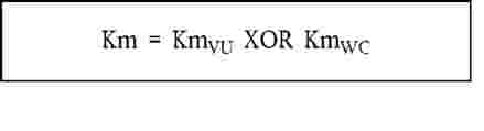
The European certification authority shall forward these keys, under appropriately secured procedures, to Member States certification authorities at their request.
CSM_037
Member States certification authorities shall:
|
— |
use Km to encrypt motion sensor data requested by motion sensor manufacturers (data to be encrypted with Km is defined in ISO 16844-3), |
|
— |
forward KmVU to vehicle unit manufacturers, under appropriately secured procedures, for insertion in vehicle units, |
|
— |
ensure that KmWC will be inserted in all workshop cards (SensorInstallationSecData in Sensor_Installation_Data elementary file) during card personalisation. |
3.1.4. T-DES session keys generation and distribution
CSM_012
Vehicle units and tachograph cards shall, as a part of the mutual authentication process, generate and exchange necessary data to elaborate a common Triple DES session key. This exchange of data shall be protected for confidentiality through an RSA crypt-mechanism.
CSM_013
This key shall be used for all subsequent cryptographic operations using secure messaging. Its validity shall expire at the end of the session (withdrawal of the card or reset of the card) and/or after 240 use (one use of the key = one command using secure messaging sent to the card and associated response).
3.2. Keys
CSM_014
RSA keys shall have (whatever the level) the following lengths: modulus n 1024 bits, public exponent e 64 bits maximum, private exponent d 1024 bits.
CSM_015
Triple DES keys shall have the form (Ka, Kb, Ka) where Ka and Kb are independent 64 bits long keys. No parity error detecting bits shall be set.
3.3. Certificates
CSM_016
RSA Public key certificates shall be “non self-descriptive““Card Verifiable“ certificates (Ref.: ISO/IEC 7816-8)
3.3.1. Certificates content
CSM_017
RSA Public key certificates are built with the following data in the following order:
|
Data |
Format |
Bytes |
Obs |
|
CPI |
INTEGER |
1 |
Certificate profile identifier (′01′ for this version) |
|
CAR |
OCTET STRING |
8 |
Certification authority reference |
|
CHA |
OCTET STRING |
7 |
Certificate holder authorisation |
|
EOV |
TimeReal |
4 |
Certificate end of validity. Optional, ′FF′ padded if not used |
|
CHR |
OCTET STRING |
8 |
Certificate holder reference |
|
n |
OCTET STRING |
128 |
Public key (modulus) |
|
e |
OCTET STRING |
8 |
Public key (public exponent) |
|
|
|
164 |
|
Notes:
|
1. |
The “Certificate Profile Identifier“ (CPI) delineates the exact structure of an authentication certificate. It can be used as an equipment internal identifier of a relevant headerlist which describes the concatenation of Data Elements within the certificate. The headerlist associated with this certificate content is as follows:
|

|
2. |
The “Certification Authority Reference“ (CAR) has the purpose of identifying the certificate issuing CA, in such a way that the data element can be used at the same time as an authority key identifier to reference the public key of the certification authority (for coding, see Key Identifier below). |
|
3. |
The “Certificate Holder Authorisation“ ((CHA) is used to identify the rights of the certificate holder. It consists of the Tachograph Application ID and of the type of equipment to which the certificate is intended (according to EquipmentType data element, “00“ for a Member State). |
|
4. |
“Certificate Holder Reference“ (CHR) has the purpose of identifying uniquely the certificate holder, in such a way that the Data Element can be used at the same time as a Subject Key Identifier to reference the Public Key of the certificate holder. |
|
5. |
Key Identifiers uniquely identify certificate holder or certification authorities. They are coded as follows:
|
|
5.2. |
Certification Authority:
The key serial number is used to distinguish the different keys of a Member State, in the case the key is changed. |
|
6. |
Certificate verifiers shall implicitly know that the public key certified is an RSA key relevant to authentication, digital signature verification and encipherement for confidentiality services (the certificate contains no Object Identifier to specify it). |
3.3.2. Certificates issued
CSM_018
The certificate issued is a digital signature with partial recovery of the certificate content in accordance with ISO/IEC 9796-2, with the “Certification Authority Reference“ appended.
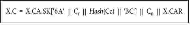
With certificate content
Notes:
|
1. |
This certificate is 194 bytes long. |
|
2. |
CAR, being hidden by the signature, is also appended to the signature, such that the public key of the certification authority may be selected for the verification of the certificate. |
|
3. |
The certificate verifier shall implicitly know the algorithm used by the certification authority to sign the certificate. |
|
4. |
The headerlist associated with this issued certificate is as follows:
|

3.3.3. Certificate verification and unwrapping
Certificate verification and unwrapping consists in verifying the signature in accordance with ISO/IEC 9796-2, retrieving the certificate content and the public key contained: X.PK = X.CA.PKoX.C, and verifying the validity of the certificate.
CSM_019
It involves the following steps:
|
|
verify signature and retrieve content:
|
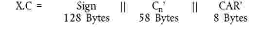
|
|
If the checks are OK the certificate is a genuine one, its content is C′. |
|
|
Verify validity. From C′:
|
|
|
Retrieve and store public key, Key Identifier, Certificate Holder Authorisation and Certificate End of Validity from C′:
|
4. MUTUAL AUTHENTICATION MECHANISM
Mutual authentication between cards and VUs is based on the following principle:
|
|
Each party shall demonstrate to the other that it owns a valid key pair, the public key of which has been certified by a Member State certification authority, itself being certified by the European certification authority. |
|
|
Demonstration is made by signing with the private key a random number sent by the other party, who must recover the random number sent when verifying this signature. |
|
|
The mechanism is triggered at card insertion by the VU. It starts with the exchange of certificates and unwrapping of public keys, and ends with the setting of a session key. |
CSM_020
The following protocol shall be used (arrows indicate commands and data exchanged (see Appendix 2)):

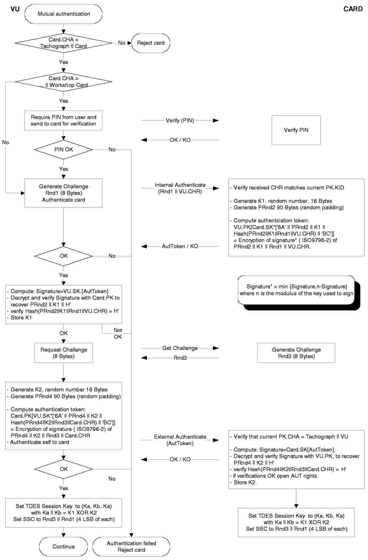
5. VU-CARDS DATA TRANSFER CONFIDENTIALITY, INTEGRITY AND AUTHENTICATION MECHANISMS
5.1. Secure messaging
CSM_021
VU-cards data transfers integrity shall be protected through Secure Messaging in accordance with references (ISO/IEC 7816-4) and (ISO/IEC 7816-8).
CSM_022
When data need to be protected during transfer, a cryptographic checksum data object shall be appended to the data objects sent within the command or the response. The cryptographic checksum shall be verified by the receiver.
CSM_023
The cryptographic checksum of data sent within a command shall integrate the command header, and all data objects sent (= > CLA = ′0C′, and all data objects shall be encapsulated with tags in which b1 = 1).
CSM_024
The response status-information bytes shall be protected by a cryptographic checksum when the response contains no data field.
CSM_025
Cryptographic checksums shall be four bytes long.
The structure of commands and responses when using secure messaging is therefore the following:
|
|
The DOs used are a partial set of the Secure Messaging DOs described in ISO/IEC 7816-4:
|
|
|
Given an unsecured command response pair:
|
|||||||||||||||
The corresponding secured command response pair is:
|
|
Secured command:
Data to be integrated in checksum = CH || PB || TPV || LPV || PV || TLE || LLE || Le || PB PB = padding bytes (80 .. 00) in accordance with ISO-IEC 7816-4 and ISO 9797 method 1. DOs PV and LE are present only when there is some corresponding data in the unsecured command. |
|||||||||||||||||||||||||||||||||||||||||||||
|
|
Secured response:
|
||||||||||||||||||||||||||||||||||||||||||||||||||||||||||||||||||||||||||||||||||||||||||
5.2. Treatment of secure messaging errors
CSM_026
When the tachograph card recognises an SM error while interpreting a command, then the status bytes must be returned without SM. In accordance with ISO/IEC 7816-4, the following status bytes are defined to indicate SM errors:
|
′66 88′ |
verification of cryptographic checksum failed, |
|
′69 87′ |
expected SM data objects missing, |
|
′69 88′ |
SM data objects incorrect. |
CSM_027
When the tachograph card returns status bytes without SM DOs or with an erroneous SM DO, the session must be aborted by the VU.
5.3. Algorithm to compute cryptographic checksums
CSM_028
Cryptographic checksums are built using a retail MACs in accordance with ANSI X9.19 with DES:
|
— |
initial stage: the initial check block y0 is E(Ka, SSC). |
|
— |
sequential stage: the check blocks y1, …, yn are calculated using Ka. |
|
— |
final stage: the cryptographic checksum is calculated from the last check block yn as follows: E(Ka, D(Kb, yn)). |
where E() means encryption with DES, and D() means decryption with DES.
The four most significant bytes of the cryptographic checksum are transferred
CSM_029
The send sequence counter (SSC) shall be initiated during key agreement procedure to:
Initial SSC: Rnd3 (4 least significant bytes) || Rnd1 (4 least significant bytes).
CSM_030
The send sequence counter shall be increased by 1 each time before a MAC is calculated (i.e. the SSC for the first command is Initial SSC + 1, the SSC for the first response is Initial SSC + 2).
The following figure shows the calculation of the retail MAC:

5.4. Algorithm to compute cryptograms for confidentiality DOs
CSM_031
Cryptograms are computed using TDEA in TCBC mode of operation in accordance with references (TDES) and (TDES-OP) and with the Null vector as Initial Value block.
The following figure shows the application of keys in TDES:

6. DATA DOWNLOAD DIGITAL SIGNATURE MECHANISMS
CSM_032
The intelligent dedicated equipment (IDE) stores data received from an equipment (VU or card) during one download session within one physical data file. This file must contain the certificates MSi.C and EQT.C. The file contains digital signatures of data blocks as specified in Appendix 7 Data Downloading Protocols.
CSM_033
Digital signatures of downloaded data shall use a digital signature scheme with appendix such, that downloaded data may be read without any decipherment if desired.
6.1. Signature generation
CSM_034
Data signature generation by the equipment shall follow the signature scheme with appendix defined in reference (PKCS1) with the SHA-1 hash function:
Signature = EQT.SK[′00′ || ′01′ || PS || ′00′ || DER(SHA-1(Data))]
|
PS |
Padding string of octets with value ′FF′ such that length is 128. |
DER(SHA-1(M)) is the encoding of the algorithm ID for the hash function and the hash value into an ASN.1 value of type DigestInfo (distinguished encoding rules):
′30′||′21′||′30′||′09′||′06′||′05′||′2B′||′0E′||′03′||′02′||′1A′||′05′||′00′||′04′||′14′||Hash Value.
6.2. Signature verification
CSM_035
Data signature verification on downloaded data shall follow the signature scheme with appendix defined in reference (PKCS1) with the SHA-1 hash function.
The European public key EUR.PK needs to be known independently (and trusted) by the verifier.
The following table illustrates the protocol an IDE carrying a Control card can follow to verify the integrity of data downloaded and stored on the ESM (external storage media). The control card is used to perform the decipherement of digital signatures. This function may in this case not be implemented in the IDE.
The equipment that has downloaded and signed the data to be analysed is denoted EQT.

(1) This way of computing the continuous driving time and the cumulative break time serves into the recording equipment for computing the continuous driving time warning. It does not prejudge the legal interpretation to be made of these times.
(2) UNKNOWN periods correspond to periods where the driver's card was not inserted in a recording equipment and for which no manual entry of driver activities was made. period of 45 minutes or more (this period may have been split in several periods of 15 minutes or more). The computations involved take into account, as needed, past activities stored on the driver card. When the driver has not inserted his card, the computations involved are based on the data memory recordings related to the current period where no card was inserted and related to the relevant slot;
(3) Directive 97/27/EC of 22 July 1997 relating to the masses and dimensions of certain categories of motor vehicles and their trailers and amending Directive 70/156/EEC (OJ L 233, 25.8.1997, p. 1).
(5) Council Recommendation 95/144/EC of 7 April 1995 on common information technology security evaluation criteria (OJ L 93, 26.4.1995, p. 27).
(6) OJ L 129, 14.5.1992, p. 95.
(7) Directive 76/114/EEC, of 18 December 1975 on the approximation of the laws of the Member States relating to statutory plates and inscriptions for motor vehicles and their trailers, and their location and method of attachment (OJ L 24, 30.1.1976, p. 1).
(8) OJ L 281, 23.11.1995, p. 31.
(9) 008
In these situations the recording equipment shall use only the tachograph card inserted in the driver slot.
(10) 095
The recording equipment shall also record and store in its data memory:
|
— |
the date and time of the last OVER SPEEDING CONTROL, |
|
— |
the date and time of the first over speeding following this OVER SPEEDING CONTROL, |
|
— |
the number of over speeding events since the last OVER SPEEDING CONTROL. |
(11) These data may be recorded at power supply reconnection only, times may be known with an accuracy to the minute.
(12) OJ L 266, 8.11.1995, p. 1.
(13) OJ L 152, 6.7.1972, p. 15.
(14) OJ L 266, 8.11.1995, p. 1.
(15) OJ L 281, 23.11.1995, p. 31.
(16) The card inserted will trigger the appropriate access rights to the downloading function and to the data.
(17) If the VU responds with a negative response containing a code meaning “request correctly received, response pending“, this value is extended to the same upper limit value of P3.
|
■ |
This symbol indicates that the service is mandatory in this diagnostic session. |
No symbol indicates that this service is not allowed in this diagnostic session.
(19) The value inserted in byte #6 of the request message is not supported, i.e. not in Table 17.
(20) The length of the message is wrong.
(21) The criteria for the request StartDiagnosticSession are not met.


All