

EUR-Lex Access to European Union law
This document is an excerpt from the EUR-Lex website
Document 02015R0504-20180215
Commission Implementing Regulation (EU) 2015/504 of 11 March 2015 implementing Regulation (EU) No 167/2013 of the European Parliament and of the Council with regard to the administrative requirements for the approval and market surveillance of agricultural and forestry vehicles (Text with EEA relevance)
Consolidated text: Commission Implementing Regulation (EU) 2015/504 of 11 March 2015 implementing Regulation (EU) No 167/2013 of the European Parliament and of the Council with regard to the administrative requirements for the approval and market surveillance of agricultural and forestry vehicles (Text with EEA relevance)
Commission Implementing Regulation (EU) 2015/504 of 11 March 2015 implementing Regulation (EU) No 167/2013 of the European Parliament and of the Council with regard to the administrative requirements for the approval and market surveillance of agricultural and forestry vehicles (Text with EEA relevance)

02015R0504 — EN — 15.02.2018 — 002.001
This text is meant purely as a documentation tool and has no legal effect. The Union's institutions do not assume any liability for its contents. The authentic versions of the relevant acts, including their preambles, are those published in the Official Journal of the European Union and available in EUR-Lex. Those official texts are directly accessible through the links embedded in this document
|
COMMISSION IMPLEMENTING REGULATION (EU) 2015/504 of 11 March 2015 implementing Regulation (EU) No 167/2013 of the European Parliament and of the Council with regard to the administrative requirements for the approval and market surveillance of agricultural and forestry vehicles (OJ L 085 28.3.2015, p. 1) |
Amended by:
|
|
|
Official Journal |
||
|
No |
page |
date |
||
|
COMMISSION IMPLEMENTING REGULATION (EU) 2016/1789 of 7 September 2016 |
L 277 |
60 |
13.10.2016 |
|
|
COMMISSION IMPLEMENTING REGULATION (EU) 2018/128 of 25 January 2018 |
L 22 |
16 |
26.1.2018 |
|
COMMISSION IMPLEMENTING REGULATION (EU) 2015/504
of 11 March 2015
implementing Regulation (EU) No 167/2013 of the European Parliament and of the Council with regard to the administrative requirements for the approval and market surveillance of agricultural and forestry vehicles
(Text with EEA relevance)
Article 1
Subject matter
This Regulation provides for the implementing measures referred to in Article 68 of Regulation (EU) No 167/2013 to establish uniform conditions for the implementation of the administrative requirements for the approval of new agricultural and forestry vehicles, as well as systems, components and separate technical units designed and constructed for such vehicles and for the placing on the market and entry into service of parts or equipment which may pose a serious risk to the correct functioning of systems that are essential for the safety of the vehicle of for its environmental performance.
Article 2
Template for the information document and for the information folder
Manufacturers applying for EU type-approval shall provide the information document and the information folder referred to in Article 22(1) and Article 22(2)(a) of Regulation (EU) No 167/2013 on the basis of the template set out in Annex I to this Regulation.
Article 3
Template for the manufacturer's certificate on access to vehicle on-board diagnostics (OBD) and to vehicle repair and maintenance information
Manufacturers concerned by Article 53(1) of Regulation (EU) No 167/2013 applying for EU type-approval shall provide the approval authority with a certificate on access to vehicle OBD and vehicle repair and maintenance information in accordance with Article 53(8) of that Regulation on the basis of the template set out in Annex II to this Regulation.
Article 4
Templates for the certificate of conformity
Manufacturers shall issue the certificate of conformity referred to in Article 33(1) of Regulation (EU) No 167/2013 in accordance with the templates set out in Annex III to this Regulation.
Article 5
Models for the statutory plate and EU type-approval mark
Manufacturers shall issue the statutory plate and the EU type-approval mark referred to in Article 34(1) and (2) of Regulation (EU) No 167/2013 in accordance with the models set out in Annex IV to this Regulation.
Article 6
Templates for the EU type-approval certificate
Approval authorities shall issue the EU type-approval certificates referred to in Article 25(1) of Regulation (EU) No 167/2013 in accordance with the templates set out in Annex V to this Regulation.
Article 7
Numbering system of EU type-approval certificates
EU type-approval certificates shall be numbered in accordance with Annex VI.
Article 8
Template for the test results sheet
Approval authorities shall issue the test results sheet referred to in Article 25(3)(a) of Regulation (EU) No 167/2013 in accordance with the template set out in Annex VII to this Regulation.
Article 9
Format of test reports
1. The format of the test reports referred to in Article 27(1) of Regulation (EU) No 167/2013 shall comply with the general requirements set out in Annex VIII to this Regulation.
2. Existing test reports for components and separate technical units issued under Directive 2003/37/EC, Directive 2007/46/EC, Directive 97/68/EC, Regulation (EU) No 595/2009 or international regulations referred to in Chapter XIII of Regulation (EU) No 167/2013 and the delegated and implementing acts adopted pursuant that Regulation, shall be accepted for the purposes of type-approval under Regulation (EU) No 167/2013 under the condition that neither the substantive requirements nor the requirements regarding the test procedures have changed since the execution of the test. Test reports fulfilling these conditions shall be listed in Annex VIII to this Regulation.
Article 10
List of parts or equipment which may pose a serious risk to the correct functioning of essential systems
The list of parts or equipment which may pose a serious risk to the correct functioning of systems that are essential for the safety of the vehicle or for its environmental performance referred to in Article 45(2) of Regulation (EU) No 167/2013 is set out in Annex IX to this Regulation.
Article 11
Template for the certificate for the placing on the market and entry into service of parts or equipment which may pose a serious risk to the correct functioning of essential systems
Approval authorities shall issue the certificate for the placing on the market and entry into service of parts or equipment which may pose a serious risk to the correct functioning of systems that are essential for the safety of the vehicle or for its environmental performance referred to in Article 46(2) of Regulation (EU) No 167/2013 in accordance with the template set out in Annex X to this Regulation.
Article 12
Numbering system of certificates for the placing on the market and entry into service of parts or equipment which may pose a serious risk to the correct functioning of essential systems
Certificates for the placing on the market and entry into service of parts or equipment which may pose a serious risk to the correct functioning of systems that are essential for the safety of the vehicle or for its environmental performance shall be numbered in accordance with Annex XI.
Article 13
Entry into force and application
This Regulation shall enter into force on the twentieth day following that of its publication in the Official Journal of the European Union.
It shall apply from 1 January 2016.
This Regulation shall be binding in its entirety and directly applicable in all Member States.
LIST OF ANNEXES
|
Annex Number |
Annex title |
|
I |
Template for the information document and for the information folder |
|
II |
Template for the manufacturer's certificate on access to vehicle on-board diagnostics (OBD) and to vehicle repair and maintenance information |
|
III |
Templates for the certificate of conformity |
|
IV |
Models for the statutory plate and EU type-approval mark |
|
V |
Templates for the EU type-approval certificate |
|
VI |
Numbering system of EU type-approval certificates |
|
VII |
Template for the test results sheet |
|
VIII |
Format of test reports |
|
IX |
List of parts or equipment which may pose a serious risk to the correct functioning of essential systems |
|
X |
Template for the certificate for the placing on the market and entry into service of parts or equipment which may pose a serious risk to the correct functioning of essential systems |
|
XI |
Numbering system of certificates for the placing on the market and entry into service of parts or equipment which may pose a serious risk to the correct functioning of essential systems |
ANNEX I
Template for the information document and for the information folder
List of Appendices
|
Appendix Number |
Appendix title |
|
1 |
Model information document relating to EU type-approval of a type of (or a type of a vehicle with regard to) an installation of an engine/engine family system |
|
2 |
Model information document relating to EU type-approval of a type of (or a type of a vehicle with regard to) an external sound level system |
|
3 |
Model information document relating to EU type-approval of an engine/engine family as a component/STU |
|
4 |
Model information document relating to EU type-approval of a type of (or a type of a vehicle with regard to) a driver information system |
|
5 |
Model information document relating to EU type-approval of a type of (or a type of a vehicle with regard to) an installation of lighting and light-signalling devices system |
|
6 |
Model information document relating to EU type-approval of a type of (or a type of a vehicle with regard to) an electro-magnetic compatibility system |
|
7 |
Model information document relating to EU type-approval of a type of (or a type of a vehicle with regard to) an installation of audible warning device(s) system |
|
8 |
Model information document relating to EU type-approval of a type of (or a type of a vehicle with regard to) the installation of rear-view mirrors as a system |
|
9 |
Model information document relating to EU type-approval of a type of (or a type of a vehicle with regard to) an installation of a crawler undercarriage system |
|
10 |
Model information document relating to EU type-approval of electro-magnetic compatibility of electrical/electronic sub-assemblies as a STU |
|
11 |
Model information document relating to EU type-approval of ballast masses as a component/STU |
|
12 |
Model information document relating to EU type-approval of a lateral and/or rear protective structure as a component/STU |
|
13 |
Model information document relating to EU type-approval of a tyre as a component |
|
14 |
Model information document relating to EU type-approval of a mechanical coupling as a component/STU |
|
15 |
Model information document relating to EU type-approval of a type of (or a type of a vehicle with regard to) a braking system |
|
16 |
Model information document relating to EU type-approval of a type of (or a type of a vehicle with regard to) a driver's exposure to noise level system |
|
17 |
Model information document relating to EU type-approval of a type of (or a type of a vehicle with regard to) a seat-belt anchorages system |
|
18 |
Model information document relating to EU type-approval of a type of (or a type of a vehicle with regard to) a protection against hazardous substances system |
|
19 |
Model information document relating to EU type-approval of a roll-over protective structure (ROPS) as a STU |
|
20 |
Model information document relating to EU type-approval of a falling objects protective structure (FOPS) as a STU |
|
21 |
Model information document relating to EU type-approval of a driver's seat as a component/STU |
|
22 |
Model information document relating to EU type-approval of a safety belt as a component/STU |
|
23 |
Model information document relating to EU type-approval of a protection against penetrating objects (OPS) as a STU |
|
24 |
Manufacturer's declaration on anti-tampering of powertrain and speed-limitation device |
PART A
INFORMATION FOLDER
1. General requirements
|
1.1. |
When applying for EU type-approval for a vehicle, system, component or separate technical unit, the manufacturer shall provide, in accordance with Article 22 of Regulation (EU) No 167/2013, an information folder which shall contain the following: (a) a list of contents; (b) the information on the type-approval procedure chosen in accordance with Article 20(1) of Regulation (EU) No 167/2013, the template for which is set out in point 2 (information folder sheet); (c) the information document as set out in Part B of this Annex; (d) all relevant data, drawings, photographs and other information as required in the information document; (e) the manufacturer's certificate providing proof of compliance to the type-approval authority on access to vehicle on-board diagnostic (OBD) and to vehicle repair and maintenance information as referred to in Article 53(8) of Regulation (EU) No 167/2013 and set out in Annex II to this Regulation; (f) for tractors type-approved with machinery mounted on them and for R- and S-category vehicles, a document setting out the contents of the EC declaration of conformity in accordance with the national provisions implementing Directive 2006/42/EC of the European Parliament and of the Council, not necessarily including the serial number and the signature; if requested by the approval authority, the manufacturer shall provide in addition any relevant documentation contained in the technical file of the machinery set out in Annex VII to that Directive, especially: — the standards and other technical specifications used, indicating the essential health and safety requirements covered by these standards, — any technical report giving the results of the tests carried out either by the manufacturer or by a body chosen by the manufacturer or his authorised representative; (g) any additional information requested by the approval authority as part of the approval procedure. (h) the manufacturer's declaration on anti-tampering of powertrain and speed-limitation device as referred to in Article 17(2)(b) of Regulation (EU) No 167/2013 and in point 4.3.2 of Annex III to Commission Delegated Regulation (EU) 2015/208 ( 1 ) according to the model established in Appendix 24 to this Annex; (i) for vehicles equipped with (an) electrical/electronic device(s) which limit its propulsion performance, data and evidence to demonstrate that modification or disconnection of the device or its wiring system will not increase the propulsion performance; (j) for vehicles of categories T2, T3 and T4.3 equipped with foldable ROPS with an automatic locking system, a certificate of the manufacturer stating that the preliminary test has been done according to the test procedure set out in point 5.5. of Part B3 of Annex IX to Commission Delegated Regulation (EU) No 1322/2014 ( 2 ). |
|
1.2. |
Applications submitted on paper shall be in triplicate. Any drawings shall be to an appropriate scale and in sufficient detail on size A4 sheets or in a folder of A4 format. Photographs (if any) shall show sufficient detail. |
|
1.3. |
Information concerning the performance of complex electronic vehicle control systems listed in Appendix 2 to Annex XXIII to Commission Delegated Regulation (EU) No 1322/2014 ( 3 ) shall be provided. |
2. Template of the information folder sheet.
Information
on the type-approval procedure chosen in accordance with Article 20(1) of Regulation (EU) No 167/2013 of the European Parliament and of the Council
Information folder sheet
A duly completed version of this statement shall be included in the information folder.
The undersigned: […(full name and position)]
Company name and address of the manufacturer (4): …
Name and address of the manufacturer's representative (if any) (4): …
Hereby applies for type-approval procedure:
(a) step-by-step type-approval (1)
(b) single-step type-approval (1)
(c) mixed type-approval (1)
Where procedures (a) or (c) are chosen, compliance with requirements as under (b) is declared for all systems, components and separate technical units.
Multi-stage type-approval chosen in accordance with Article 20(5) of Regulation (EU) No 167/2013: yes/no (1)
Information on the vehicle(s) to be filled in, if application is for EU whole-vehicle type-approval:
|
1.1 |
Make (trade name of the manufacturer) (4): … |
|
1.2. |
Type (2): …
|
|
1.3. |
Category, subcategory and speed index of the vehicle (3): … |
Applies for type-approval of:
(a) a complete vehicle type (1)
(b) completed vehicle type (1)
(c) an incomplete vehicle type (1)
(d) a vehicle type with complete and incomplete variants (1)
(e) a vehicle type with completed and incomplete variants (1)
Information to be filled in, if application is for type-approval of a system/component/separate technical unit (1):
|
2.1. |
Make(s) (trade name(s) of manufacturer): … |
|
2.2. |
Type (5): …
|
|
2.8. |
Virtual and/or self-testing (1)
|
Place: …
Date: …
Signature: …
Name and position in the company: …
Explanatory notes relating to the information folder sheet
(Footnote markers, footnotes and explanatory notes not to be stated on the information folder sheet)
(1) Delete if not applicable.
(2) Indicate the alphanumeric code Type-Variant-Version or ‘TVV’ allocated to each type, variant and version as set out in point 2.3 of Part B of Annex I to this Regulation. For the identification of variant and versions it may be employed the matrix set out in point 2.2 of Part B of Annex I to this Regulation.
(3) Classified according to Article 4 of Regulation (EU) No 167/2013, the coding shall be indicated, e.g. ‘T4.3a’ for a low-clearance tractor with a maximum design speed below or equal to 40 km/h.
(4) In case of multi-stage type-approval supply this information for each stage(s).
(5) For engines indicate the information relative to the engine type or the engine family type, as applicable without the type-approval extension number.
PART B
INFORMATION DOCUMENT
1. GENERAL REQUIREMENTS
|
1.1. |
The information document shall have a reference number supplied by the applicant. |
|
1.2. |
Where the particulars appearing in the information document for vehicle approval have changed, the manufacturer shall submit revised pages to the approval authority showing clearly the nature of the change(s) and the date of re-issue. |
2. TYPE-APPROVAL OF VEHICLES
|
2.1. |
All information documents shall contain the following: — the matrix in point 2.2 to identify the versions and variants of the vehicle intended for type-approval, — a list of items applicable to the (sub-)category and to the technical characteristics of the vehicle from which content has been extracted, adhering to the numbering system of the total list set out in point 5. |
|
2.2. |
Matrix showing the combinations of the entries listed in point 5 within the versions and variants of the vehicle type
Variants and version matrix
|
|
2.3 |
Type-, variant- and version designations
|
3. TYPE-APPROVAL OF SYSTEMS, COMPONENTS AND SEPARATE TECHNICAL UNITS
|
3.1. |
For a system, component or separate technical unit as listed in Table 1-1 the manufacturer shall complete the applicable appendix to this Annex. In addition to the Annexes mentioned in Table 1-1, the systems, components and separate technical units shall comply with the following requirements: (a) arrangements for type-approval procedures (Annex III to Commission Delegated Regulation (EU) No 1322/2014) (b) conformity of production (CoP) (Annex IV to Commission Delegated Regulation (EU) No 1322/2014) (c) access to repair and maintenance information (Annex V to Commission Delegated Regulation (EU) No 1322/2014)
Table 1-1 Lists of systems, components and separate technical units which may be subject to an EU type-approval
|
||||||||||||||||||||||||||||||||||||||||||||||||||||||||||||||||||||||||||||||||||||||||||||||||||||||||||||||||||||||||||||||||
4. TYPE-APPROVAL NUMBERS OR TEST REPORTS NUMBERS OF THE APPLICABLE SUBJECTS
|
4.1. |
The manufacturer shall supply the information required by Table 1-2 in respect of the applicable subjects for the vehicle set out in Annex I to Regulation (EU) No 167/2013. All relevant approvals and test reports (if available) for each subject shall be included. However, information in respect of systems, components or separate technical units need not be given here so long as such information is included in the correspondent approval certificate.
Table 1-2 Type-approval number and test report overview
Signed: … Position in company: … Date: … |
||||||||||||||||||||||||
|
4.2. |
For those subjects referred to in Annex I to Regulation (EU) No 167/2013 whose approvals have been granted in accordance with Directive 97/68/EC, Regulation (EC) No 595/2009 or the UNECE regulations referred to in Article 49 of Regulation (EU) No 167/2013 (UNECE approvals), or are based on complete test reports issued on the basis of the OECD standard Codes as an alternative to the test reports drawn up under that Regulation and the delegated acts adopted pursuant to it, the manufacturer shall supply the information required in point 5 only if it is not already provided in the correspondent approval certificate and/or test report. However, the information referred to in the certificate of conformity (Annex III to this Regulation) shall be supplied in any case. |
5. INFORMATION DOCUMENT DATA ENTRIES
A. GENERAL INFORMATION
1. GENERAL INFORMATION CONCERNING VEHICLES
|
1.1. |
Make (trade name of manufacturer) (18): … |
|
1.2. |
Type (17): …
|
|
1.3. |
Category, subcategory and speed index of vehicle (2): … |
|
1.4. |
Company name and address of manufacturer (18): …
|
|
1.5. |
Manufacturer's statutory plate(s)
|
|
1.6. |
Vehicle identification number
|
2. GENERAL INFORMATION CONCERNING SYSTEMS, COMPONENTS OR SEPARATE TECHNICAL UNITS
|
2.1. |
Make(s) (trade name(s) of manufacturer): … |
|
2.2. |
Type (49): …
|
|
2.3. |
Company name and address of manufacturer: …
|
|
2.4. |
For systems and separate technical units, vehicle(s) for which they are intended for (21):
|
|
2.5. |
Additional general information for engines
|
3. GENERAL CONSTRUCTION CHARACTERISTICS
|
3.1. |
Photographs or drawings of a representative version of the vehicle: … |
|
3.2. |
Scale and dimensioned drawing of the whole vehicle: … |
|
3.3. |
Axles and wheels:
|
|
3.4. |
For C-category vehicles
|
|
3.5. |
Chassis
|
|
3.6. |
Material used for the bodywork: … |
|
3.7. |
Position and arrangement of the engine: … |
|
3.8. |
Position of the steering wheel: left/right/centre (4): … |
|
3.9. |
Vehicle is equipped to be driven in right/left (4) -hand traffic and in countries that use metric/metric and imperial units in the speedometer (4); |
|
3.10. |
T- or C-category vehicles equipped for forestry applications: yes/no (4) |
|
3.11. |
T- or C-category vehicles equipped for protection against hazardous substances: yes/no (4) |
|
3.12. |
For R- and S-category vehicles, type of braking: unbraked/inertia-braked/continuous braked/semi-continuous braked/hydraulic braked/pneumatic braked (4) |
4. MASSES AND DIMENSIONS
(in kg and mm) (Refer to drawings where applicable)
4.1 Range of vehicle mass (overall)
4.1.1. Unladen mass
|
4.1.1.1. |
Unladen mass(es) in running order (13): 4.1.1.1.1. Maximum: … kg (30) 4.1.1.1.2. Minimum: … kg (30) 4.1.1.1.3. Distribution of this (these) mass(es) among the axles: … kg 4.1.1.1.4. In the case of a rigid drawbar or centre- axle R- or S-category vehicle indicate the vertical load on the coupling point (S): … kg |
4.1.2. Maximum mass(es), as declared by the manufacturer
|
4.1.2.1. |
Technically permissible maximum laden mass(es) of the vehicle (13): … kg
|
|
4.1.2.2. |
Mass(es) and tyre(s)
|
||||||||||||||||||||||||||||||||||||||||||||||||||||||||||||||||||||||||||||||||||||||||||||||||||||||||||||||
|
4.1.2.3. |
Mass(es) and crawler undercarriage
|
||||||||||||||||||||||||||||||||||||||||||
▼M1 —————
|
4.1.3. |
Technically permissible towable mass(es) for T- or C-category vehicles for each chassis/ braking configuration of the R- or S-category vehicle (for R- and S-category vehicles, indicate the maximum permissible load(s) on the rear coupling point):
|
||||||||||||||||||||||||
|
4.1.4. |
Total technically permissible mass(es) of the tractor (T- or C-category vehicle) and towed vehicle (R- or S-category vehicle) combination for each chassis/braking configuration of the R- or S-category vehicle:
|
▼M1 —————
4.2. Range of vehicle dimensions (overall)
4.2.1. For incomplete vehicles
4.2.1.1. Length (31)
|
4.2.1.1.1. |
Maximum permissible length for the completed vehicle: … mm |
|
4.2.1.1.2. |
Minimum permissible length for the completed vehicle: … mm |
4.2.1.2. Width (32)
|
4.2.1.2.1. |
Maximum permissible width for the completed vehicle: … mm |
|
4.2.1.2.2. |
Minimum permissible width for the completed vehicle: … mm |
|
4.2.1.3. |
Height (in running order) (33)
|
|
4.2.1.4. |
Forward overhang (34): … mm
|
|
4.2.1.5. |
For T- and C-category vehicles: rear overhang (35): … mm
|
|
4.2.1.6. |
For T- and C-category vehicles: ground clearance (36)
|
|
4.2.1.7. |
Extreme permissible positions of the centre of gravity for the completed vehicle: … mm
|
4.2.2. For complete/completed (4) vehicles
|
4.2.2.1. |
Overall dimensions of the vehicle, including mechanical coupling: 4.2.2.1.1. Length for on-road use (31)
4.2.2.1.2. Width for on-road use (32)
4.2.2.1.3. Height for on-road use (33) (47)
|
|
4.2.2.2. |
Forward overhang (34) (48)
|
|
4.2.2.3. |
Rear overhang (35)
|
|
4.2.2.4. |
Ground clearance (36)
|
|
4.2.2.5. |
Wheelbase (37): … mm |
|
4.2.2.6. |
Distance(s) between consecutive axles 1-2: … mm 2-3: … mm, 3-4: … mm, etc. |
|
4.2.2.7. |
For rigid draw bar and centre axle R- and S-category vehicles: 4.2.2.7.1. Distance between the coupling point and the first axle: … mm 4.2.2.7.2. Distance between the coupling point and the last axle: … mm |
|
4.2.2.8. |
Maximum and minimum width of track of each axle (measured between the symmetry planes of the single or twin tyres or of the tyres in triple formation normally fitted) (to be stated by the manufacturer) (38): 4.2.2.8.1. Maximum: Axle 1 … mm Axle 2 … mm Axle …:… mm 4.2.2.8.2. Minimum: Axle 1 … mm Axle 2 … mm Axle …:… mm |
|
4.2.2.9. |
Position of centre of gravity of the vehicle in the longitudinal, transverse and vertical direction: …
|
5. GENERAL POWERTRAIN CHARACTERISTICS
5.1. Maximum vehicle speed
5.1.1. Forward maximum vehicle speed
|
5.1.1.1. |
Declared maximum design vehicle speed: … km/h |
|
5.1.1.2. |
Calculated maximum design vehicle speed in top gear (show factors used in calculation) (41): … km/h |
|
5.1.1.3. |
Measured maximum vehicle speed: … km/h (41) |
5.1.2. Rearward maximum vehicle speed (54)
|
5.1.2.1. |
Declared rearward maximum design vehicle speed: … km/h |
▼M1 —————
|
5.2. |
Rated engine net power: … kW, at … min–1 (in accordance with UNECE Regulation No 120 (OJ L 257, 30.9.2010, p. 280)) |
|
5.3. |
Maximum engine net power: … kW, at … min–1 (in accordance with UNECE Regulation No 120 (OJ L 257, 30.9.2010, p. 280)) |
|
5.4. |
Maximum engine torque: … Nm, at … min–1 (in accordance with UNECE Regulation No 120 (OJ L 257, 30.9.2010, p. 280)) |
|
5.5. |
Fuel type (9): … |
|
5.6. |
Actual forward movement of powered wheels corresponding to one complete revolution of the wheel: … mm |
B. INFORMATION ON ENVIRONMENTAL AND PROPULSION PERFORMANCE
6. ESSENTIAL CHARACTERISTICS OF THE PARENT ENGINE/ENGINE (4)
|
6.1. |
Cycle: four stroke/two stroke (4) |
|
6.2. |
Bore (12) … mm |
|
6.3. |
Stroke (12): … mm |
|
6.4. |
Number … and layout (26) … of cylinders |
|
6.5. |
Engine capacity: … cm3 |
|
6.6. |
Rated speed: … min–1 |
|
6.7. |
Maximum torque speed: … min–1 |
|
6.8. |
Volumetric compression ratio (7): … |
|
6.9. |
Combustion system description: … |
|
6.10. |
Drawing(s) of combustion chamber and piston crown: … |
|
6.11. |
Minimum cross sectional area of inlet and outlet ports: … |
|
6.12. |
Cooling system
6.12.1. Liquid
6.12.2. Air
|
|
6.13. |
Temperature permitted by the manufacturer
|
|
6.14. |
Pressure charger
|
|
6.15. |
Intake system: maximum allowable intake depression at rated engine speed and at 100 % load: … kPa |
|
6.16. |
Exhaust system: maximum permissible exhaust backpressure at rated engine speed and at 100 % load: … kPa |
|
6.17. |
Measures taken against air pollution
|
|
6.18. |
Fuel feed for diesel engines
6.18.1. Feed pump 6.18.1.1 Pressure (7) … kPa or characteristic diagram: … 6.18.2. Injection system 6.18.2.1. Pump 6.18.2.1.1. Make(s): … 6.18.2.1.2. Type(s): … 6.18.2.1.3. Delivery: … and … mm3 (7) per stroke or cycle at full injection at pump speed of: … rpm (rated) and: … rpm (maximum torque) respectively, or characteristic diagram: … 6.18.2.1.3.1. Method used: on engine/on pump bench (4) 6.18.2.2. Injection advance: 6.18.2.2.1. Injection advance curve (7): … 6.18.2.2.2. Timing (7): … 6.18.2.3. Injection piping: 6.18.2.3.1. Length: … mm 6.18.2.3.2. Internal diameter: … mm 6.18.2.4. Injector(s) 6.18.2.4.1. Make(s) … 6.18.2.4.2. Type(s): … 6.18.2.4.3. Opening pressure (7): … kPa, or characteristic diagram: … 6.18.2.5. Governor 6.18.2.5.1. Make(s) … 6.18.2.5.2. Type(s): … 6.18.2.5.3. Speed at which cut-off starts under full load (7): … min–1 6.18.2.5.4. Maximum no-load speed (7): … min–1 6.18.2.5.5. Idling speed (7): … min–1 6.18.2.6. Cold-start system 6.18.2.6.1. Make(s): … 6.18.2.6.2. Type(s): … 6.18.2.6.3. Description: … |
|
6.19. |
Fuel for petrol engines
|
|
6.20. |
Valve timing
|
|
6.21. |
Porting configuration
|
|
6.22. |
Ignition system
6.22.1. Ignition coil
|
7. ESSENTIAL CHARACTERISTICS OF THE ENGINE FAMILY
7.1. Common parameters (56)
|
7.1.1. |
Combustion cycle: positive ignition/compression ignition (4) |
|
7.1.2. |
Cooling medium … |
|
7.1.3. |
Method of air aspiration: … |
|
7.1.4. |
Combustion chamber type and design: … |
|
7.1.5. |
Valve and porting configuration, size and number: … |
|
7.1.6. |
Fuel system: … |
|
7.1.7 |
Engine management systems (proof of identity pursuant to drawing number(s))
|
|
7.1.8 |
Exhaust after-treatment system (3): … |
7.2. Engine family listing
|
7.2.1. |
Name of engine family: … |
|
7.2.2. |
Specifications of engines within the family:
|
||||||||||||||||||||||||||||||||||||||||||||||||||||||||||||||||||||||||||||||
8. ESSENTIAL CHARACTERISTICS OF THE ENGINE TYPE WITHIN THE FAMILY
|
8.1. |
Cycle: four stroke/two stroke (4): … |
|
8.2. |
Bore (12): … mm |
|
8.3. |
Stroke (12): … mm |
|
8.4. |
Number … and layout (26) … of cylinders |
|
8.5. |
Engine capacity: … cm3 |
|
8.6. |
Rated speed: … min–1 |
|
8.7. |
Maximum torque speed: … min–1 |
|
8.8. |
Volumetric compression ratio (7): … |
|
8.9. |
Combustion system description: … |
|
8.10. |
Drawings of combustion chamber and piston crown: … |
|
8.11. |
Minimum cross sectional area of inlet and outlet ports: … |
|
8.12. |
Cooling system
8.12.1. Liquid
8.12.2. Air 8.12.2.1. Blower: yes/no (4) 8.12.2.1.1. Characteristics of the blower. … 8.12.2.1.2. Drive ratio(s) (if applicable): … |
|
8.13. |
Temperature permitted by the manufacturer
|
|
8.14. |
Pressure charger
|
|
8.15. |
Intake system: maximum allowable intake depression at rated engine speed and at 100 % load: … kPa |
|
8.16. |
Exhaust system: maximum permissible exhaust backpressure at rated engine speed and at 100 % load: … kPa |
|
8.17. |
Measures taken against air pollution
8.17.1. Device for recycling crankcase gases: yes/no (4) 8.17.2. Additional anti-pollution devices (if any): 8.17.2.1. Catalytic converter: yes/no (4) 8.17.2.1.1. Make: … 8.17.2.1.2. Type … 8.17.2.1.3. Number of catalytic converters and elements … 8.17.2.1.4. Dimensions and volume of the catalytic converter(s): … 8.17.2.1.5. Type of catalytic action … 8.17.2.1.6. Total charge of precious metals: … 8.17.2.1.7. Relative concentration: … 8.17.2.1.8. Substrate (structure and material): … 8.17.2.1.9. Cell density: … 8.17.2.1.10. Type of casing for the catalytic converter(s): … 8.17.2.1.11. Location of the catalytic converter(s) (place(s) and maximum/minimum distance(s) from engine: … 8.17.2.1.12. Normal operating range: … K 8.17.2.1.13. Consumable reagent (where appropriate) … 8.17.2.1.13.1. Type and concentration of reagent needed for catalytic action: … 8.17.2.1.13.2. Normal operational temperature range of reagent: … K 8.17.2.1.13.3. International standard (if applicable): … 8.17.2.1.14. NOx sensor: yes/no (4) 8.17.2.1.15. Oxygen sensor: yes/no (4) 8.17.2.1.15.1. Make: … 8.17.2.1.15.2. Type … 8.17.2.1.15.3. Location: … 8.17.2.1.16. Air injection: yes/no (4) 8.17.2.1.16.1. Type: pulse air/air pump/other (4) (if other specify: …) 8.17.2.1.17. EGR: yes/no (4) 8.17.2.1.17.1. Characteristics (cooled/uncooled, high pressure/low pressure, etc.): … 8.17.2.1.18. Particulate trap: yes/no (4) 8.17.2.1.18.1. Dimensions and capacity of the particulate trap: … 8.17.2.1.18.2. Type and design of the particulate trap: … 8.17.2.1.18.3. Location (place(s) and maximum/minimum distance(s) from engine: … 8.17.2.1.18.4. Method or system of regeneration, description and/or drawing: … 8.17.2.1.18.5. Normal operating temperature range: … K and pressure range: …kPa 8.17.2.1.19. Other systems: yes/no (4) 8.17.2.1.19.1. Description and operation: … |
|
8.18. |
Fuel feed for diesel engines
8.18.1. Feed pump 8.18.1.1 Pressure (7) … kPa or characteristic diagram: … 8.18.2. Injection system 8.18.2.1. Pump 8.18.2.1.1. Make(s): … 8.18.2.1.2. Type(s): … 8.18.2.1.3. Delivery: … and …mm3 (7) per stroke or cycle at full injection at pump speed of: … rpm (rated) and: … rpm (maximum torque) respectively, or characteristic diagram: … 8.18.2.1.3.1. Method used: on engine/on pump bench (4) 8.18.2.2. Injection advance: 8.18.2.2.1. Injection advance curve (7): … 8.18.2.2.2. Timing (7): … 8.18.2.3. Injection piping: 8.18.2.3.1. Length: … mm 8.18.2.3.2. Internal diameter: … mm 8.18.2.4. Injector(s) 8.18.2.4.1. Make(s) … 8.18.2.4.2. Type(s): … 8.18.2.4.3. Opening pressure (7): … kPa, or characteristic diagram: … 8.18.2.5. Governor 8.18.2.5.1. Make(s) … 8.18.2.5.2. Type(s): … 8.18.2.5.3. Speed at which cut-off starts under full load (7): … min–1 8.18.2.5.4. Maximum no-load speed (7): … min–1 8.18.2.5.5. Idling speed (7): … min–1 8.18.2.6. Cold-start system 8.18.2.6.1. Make(s): … 8.18.2.6.2. Type(s): … 8.18.2.6.3. Description: … |
|
8.19. |
Fuel feed for petrol engines
|
|
8.20. |
Valve timing
|
|
8.21. |
Porting configuration
|
|
8.22. |
Ignition system
8.22.1. Ignition coil
|
9. ENERGY STORAGE DEVICE(S) (11)
9.1. Description: battery/capacitor/flywheel/generator (4)
9.2. Identification number: …
9.3. Kind of electrochemical couple: …
9.4. Energy stored
9.4.1. For battery, voltage: … and capacity: … Ah in 2h
9.4.2. For capacitor: … J
9.4.3. For flywheel/generator (4): … J
9.4.3.1. Flywheel moment of inertia: … kg m2
9.4.3.1.1. Additional moment of inertia if no gear is engaged: … kg m2
9.5. Charger: on-board/external/without (4)
10. EXTERNAL SOUND LEVEL
10.1. External sound level declared by the manufacturer
|
10.1.1. |
Moving: … dB(A) |
|
10.1.2 |
Stationary: … dB(A) |
|
10.1.3. |
At engine speed: … min–1 |
|
10.2. |
Brief description and schematic drawing of exhaust system (including the air intake system, the devices for noise and tailpipe emission control): … |
|
10.3. |
Air-intake system
|
|
10.4. |
Exhaust system
|
|
10.5. |
Details of any non-engine related devices designed to reduce noise (if not covered by other items): … |
11. DRIVE-TRAIN AND CONTROL (13)
11.1. Brief description and schematic drawing of the vehicle drive-train and its control system (gear shift control, clutch control or any other element of drive-train):
11.2. Transmission
11.2.1. Brief description and schematic drawing of gear shift system(s) and its control: …
11.2.2. Diagram and or drawing of the transmission system: …
11.2.3. Type of transmission: mechanical/hydraulic/electric/other (4) (if other specify …)
11.2.4. Brief description of the electrical/electronic components (if any): …
11.2.5. Location relative to the engine: …
11.2.6. Method of control: …
11.2.7. Transfer box: with/without (4)
11.2.8. Type of gear shift system(s) (24): …
11.3. Clutch (if any)
11.3.1. Brief description and schematic drawing of the clutch and its control system:
11.3.2. Maximum torque conversion: …
11.4. Gear ratios
|
Gear |
Internal gearbox ratios (ratios of engine to gearbox output shaft revolutions) |
Internal transfer box ratios (ratios of engine to transfer box output shaft revolutions) |
Final drive ratio(s) (ratio of gearbox output shaft to driven wheel revolutions) |
Total gear ratios |
Ratio (engine speed/vehicle speed) for manual transmission only |
|
Maximum for CVT (1) 1 2 3 |
|
|
|
|
|
|
Minimum for CVT (1) Reverse 1 … |
|
|
|
|
|
|
(*1) Continuously variable transmission |
|||||
11.5. Differential lock
11.5.1. Differential lock: yes/no/optional (4)
C. INFORMATION ON FUNCTIONAL SAFETY
12. PROPULSION AND/OR DRIVE-TRAIN OUTPUT GOVERNORS
|
12.1. |
Number of speed governors: … |
|
12.2. |
Nominal cut-off point No 1: …
|
|
12.3. |
Nominal cut-off point No 2: …
|
|
12.4. |
The stated purpose of governor(s): maximum design vehicle speed limitation/maximum power limitation/engine over-speed protection (4): … |
|
12.5. |
Adjustable speed limitation device complying with the requirements for N2- and N3-category vehicles set out in points 1 and 2, Part II point 13.2, Part III points 21.2 and 21.3, Annex 5 point 1 and Annex 6 to UNECE Regulation No 89 (OJ L 158, 19.6.2007, p. 1). with relevant documentation included in the information document: yes/no/not applicable (4) |
13. STEERING
|
13.1. |
Schematic diagram of steered axle(s) showing steering geometry: … |
|
13.2. |
Steering category: manual/power-assisted/servo steering/differential (4) |
|
13.3. |
Transmission and control of steering
|
|
13.4. |
Maximum turning angle of the wheels (if fitted)
|
|
13.5. |
Minimum turning circle (without braking) (42)
|
|
13.6. |
Steering for fast (‘b’ speed index) T-category vehicles
|
|
13.7. |
Complex electronic control systems that affect the steering function
|
14. SPEEDOMETER, ODOMETER, TACHOMETER AND HOUR METER
14.1. Speedometer
|
14.1.1. |
Photographs and/or drawings of the complete system: … |
|
14.1.2. |
Vehicle speed range displayed: … |
|
14.1.3. |
Tolerance of the measuring mechanism of the speedometer: … |
|
14.1.4. |
Technical constant of the speedometer: … |
|
14.1.5. |
Method of operation and description of the drive mechanism: … |
|
14.1.6. |
Overall transmission ratio of the drive mechanism: … |
|
14.1.7. |
Design of the instrument dial or of the other forms of read-out: … |
|
14.1.8. |
Brief description of the electrical/electronic components: … |
14.2. Odometer
|
14.2.1. |
Tolerance of the measuring mechanism of the odometer: … |
|
14.2.2. |
Method of operation and description of the drive mechanism: … |
14.3. Tachometer
|
14.3.1. |
Tolerance of the measuring mechanism of the tachometer: … |
|
14.3.2. |
Method of operation and description of the drive mechanism: … |
14.4. Hour meter
|
14.4.1. |
Tolerance of the measuring mechanism of the hour meter: … |
|
14.4.2. |
Method of operation and description of the drive mechanism: … |
15. FIELD OF VISION
|
15.1. |
Drawing(s) and/or photograph(s) showing the location of component parts within the 180 o forward field of vision: … |
|
15.2. |
Requirements under ISO 5721-1:2013 (Agricultural tractors — Requirements, test procedures and acceptance criteria for the operator's field of vision — Part 1: Field of vision to the front) are met with relevant documentation included in the information document: yes/no (4) |
|
15.3. |
Requirements under ISO 5721-2:2014 (Agricultural tractors — Requirements, test procedures and acceptance criteria for the operator's field of vision — Part 2: Field of vision to the side and to the rear) are met with relevant documentation included in the information document: yes/no (4) |
16. WINDSCREEN WIPERS AND WASHERS AND DEFROSTING AND DEMISTING
16.1. Windscreen wipers
|
16.1.1. |
Requirements under ISO 5721-1:2013 (Agricultural tractors — Requirements, test procedures and acceptance criteria for the operator's field of vision — Part 1: Field of vision to the front) are met with relevant documentation included in the information document: yes/no (4) |
|
16.1.2. |
Alternatively to entry 16.1.1, provide a detailed technical description (including photographs or drawings) and the number and frequency of its operation: … |
16.2. Windscreen washer
|
16.2.1. |
Detailed technical description (including photographs or drawings): … |
|
16.2.2. |
Capacity of the reservoir: … l |
16.3. Defrosting and demisting
|
16.3.1. |
Detailed technical description (including photographs or drawings): … |
|
16.3.2. |
Maximum electrical consumption: … kW |
17. GLAZING
|
17.1. |
The following requirements under UNECE Regulation 43 (OJ L 42, 12.2.2014, p. 1) are met with the relevant documentation included in the information document: … |
|
17.2. |
Alternatively to entry 17.1, provide the following information:
|
18. REAR-VIEW MIRRORS
|
18.1. |
Number and class(es) of the mirrors: … |
|
18.2. |
Requirements under UNECE Regulation No 46 (OJ L 177, 10.7.2010, p. 211) are met with the relevant documentation included in the information document: yes/no/not applicable (4) |
|
1.8.3. |
Requirements under UNECE Regulation No 81 (OJ L 185, 13.7.2012, p. 1) are met with the relevant documentation included in the information document: yes/no/not applicable (4) |
|
18.4. |
Drawing(s) for the identification of the mirror showing the position of the mirror relative to the vehicle structure: … |
|
18.5. |
Details of the method of attachment including that part of the vehicle structure to which it is attached: … |
|
18.6. |
Brief description of the electrical/electronic components of the adjustment system: … |
|
18.7 |
Technical description of the defrosting and demisting system of the mirrors: … |
|
18.8. |
Optional equipment that might restrict the field of vision to the rear: … |
|
18.9. |
Field of vision for rear view mirror(s) of class II
|
19. DEVICES FOR INDIRECT VISION OTHER THAN MIRRORS (OPTIONAL)
|
19.1. |
Type and characteristics (such as a complete description of the device): … |
|
19.2. |
In the case of a camera-monitor device, the detection distance (mm), contrast, luminance range, glare correction, display performance (black and white/colour (4)), image repetition frequency, luminance reach of the monitor (4): … |
|
19.3. |
Sufficiently detailed drawings to identify the complete device, including installation instructions: … |
|
19.4. |
Requirements under ISO 5721-2:2014 (Agricultural tractors — Requirements, test procedures and acceptance criteria for the operator's field of vision — Part 2: Field of vision to the side and to the rear) are met with relevant documentation included in the information document: yes/no (4) |
20. DRIVER INFORMATION SYSTEMS
|
20.1. |
Requirements under ISO 15077:2008 (Tractors and self-propelled machinery for agriculture — Operator controls — Actuating forces, displacement, location and method of operation) Annex B on operator controls associated with virtual terminals are met with relevant documentation included in the information document: yes/no (4) |
21. INSTALLATION OF LIGHTING, LIGHT-SIGNALLING DEVICES, INCLUDING AUTOMATIC SWITCHING OF LIGHTING
|
21.1. |
List of all devices (mentioning the number, make(s),type, component type-approval mark(s), the maximum intensity of the main-beam headlamps, colour, the corresponding tell-tale); the list may include several types of device for each function; in addition, the list may include in respect of each function the additional annotation ‘or equivalent devices’: … |
|
21.2. |
A diagram of the lighting and signalling installation as a whole, showing the position of the various devices on the vehicle: … |
|
21.3. |
Dimensioned sketches of the exterior of the vehicle showing the location of the lighting and light-signalling devices, number and colour of lights: … |
|
21.4. |
For every lamp and reflector, supply the following information:
|
|
21.5. |
Description/drawing and type of headlamp levelling device (e.g. automatic, stepwise manually adjustable, continuously manually adjustable) (4): …
|
|
21.6. |
For R- and S-category vehicles, description of the power connection for lighting and light-signalling devices: … |
|
21.7. |
Brief description of the electrical and/or electronic components used in the lighting system and in the light-signalling system: … |
22. VEHICLE OCCUPANT PROTECTION, INCLUDING INTERIOR FITTINGS AND OTHER WEATHER PROTECTION ARRANGEMENTS
22.1. Bodywork
|
22.1.1. |
Materials used and methods of construction: … |
22.2. Burning rate of cab material
|
22.2.1. |
Burning rate not exceeding the maximum rate of 150 mm/min in accordance with the requirements under ISO 3795:1989 (Road vehicles, and tractors and machinery for agriculture and forestry — Determination of burning behaviour of interior materials) with the relevant documentation included in the information document: yes/no (4). |
22.3. Interior protection for occupants
|
22.3.1. |
Photographs, drawings and/or an exploded view of the interior fittings, showing the parts in the passenger compartment and the materials used (with the exception of interior rear view mirrors), arrangement of controls, seats and their rear parts, head restraints, roof and opening roof, doors and window winders and other non-specified fittings: … |
|
22.3.2. |
For vehicles equipped with steering wheel and bench seats or bucket seats in more than one row, environment of the rear passenger seats, if fitted, complying with Annex XVII to Commission Delegated Regulation (EU) No 3/2014 ( 4 ): yes/no (4) |
22.4. Head restraint(s)
|
22.4.1. |
Provided: yes/no (4) |
|
22.4.2. |
Requirements under UNECE Regulation 25 (OJ L 215, 14.8.2010, p. 1) are met with the relevant documentation included in the information document: yes/no (4) |
|
22.4.3. |
Type: integrated/detachable/separate (4) |
|
22.4.4. |
Detailed description of the head restraint, specifying in particular the nature of the padding material or materials and, where applicable, the position and specifications of the braces and anchorage pieces for the type of seat for which approval is sought: … |
|
22.4.5. |
In the case of a‘separate’ head restraint:
|
22.5. Foot rests
|
22.5.1. |
Photographs and/or drawings of the operating space showing the true, effective number, location and dimensions of the footrests: … |
22.6. Other weather protection arrangements
|
22.6.1. |
Description (Including photographs and drawings): … |
|
22.6.2. |
Internal and external dimensions: … mm × … mm × … mm … mm × … mm × … mm |
23. VEHICLE EXTERIOR AND ACCESSORIES
|
23.1. |
General arrangement (drawing or photographs accompanied if necessary by dimensional details and/or text) indicating the position of the attached sections and views, of any parts of the exterior surface which can be regarded as critical for external projections, for example, and where relevant: bumpers, floor line, door and window pillars, air-intake grilles, radiator grille, windscreen wipers, rain gutter channels, handles, slide rails, flaps, door hinges and locks, hooks, eyes, winches, decorative trim, badges, emblems and recesses and any other parts of the exterior surface which can be regarded as critical with regard to the risk or seriousness of bodily injury to a person hit by the external surface or brushing against it in the event of a collision (e.g. lighting equipment): … |
|
23.2. |
A detailed description, including photographs and/or drawings, of the vehicle with respect to the structure, the dimensions, the relevant reference lines and the constituent materials of the frontal part of the vehicle (interior and exterior), including detail of any active pedestrian protection system installed: … … |
|
23.3. |
Drawing of the floor line: … |
24. ELECTRO-MAGNETIC COMPATIBILITY (EMC)
|
24.1. |
Schedule describing all projected combinations of relevant vehicle electrical/electronic systems or ESAs, body styles (60), variations in body material, general wiring arrangements, engine variations, left-hand/right-hand drive versions and wheelbase versions: … |
|
24.2. |
Requirements under UNECE Regulation No 10 (OJ L 254, 20.9.2012, p. 1) are met with the relevant documentation included in the information document: yes/no (4) |
|
24.3. |
Requirements under ISO 14982:1998 (Agricultural and forestry machinery — Electromagnetic compatibility — Test methods and acceptance criteria) are met with relevant documentation included in the information document: yes/no (4) |
|
24.4. |
Alternatively to entry 24.2 or entry 24.3, provide the following information:
|
25. AUDIBLE WARNING DEVICE(S)
|
25.1. |
Component type-approval for an audible warning device granted according to the requirements for N-category vehicles in the UNECE Regulation No 28 (OJ L 323, 6.12.2011, p. 33), with relevant documentation included in the information document: yes/no (4) |
|
25.2. |
Summary description of device(s) used: … |
|
25.3. |
Drawing(s) showing the location of the audible warning device(s) in relation to the structure of the vehicle: … |
|
25.4. |
Details of the method of attachment, including the part of the vehicle structure to which the audible warning device(s) is (are) attached: … |
|
25.5. |
Electrical/pneumatic circuit diagram: …
|
|
25.6. |
Drawing of the mounting device: … |
26. HEATING SYSTEM AND AIR-CONDITIONING
|
26.1. |
Heating system tested in accordance with section 8 of ISO 14269-2:1997 (Tractors and self-propelled machines for agriculture and forestry — Operator enclosure environment — Part 2: Heating, ventilation and air-conditioning test method and performance) and test reports are included in the information document: yes/no/not applicable (4) |
|
26.2. |
Air-conditioning system tested in accordance with section 9 of ISO 14269-2:1997 (Tractors and self-propelled machines for agriculture and forestry — Operator enclosure environment — Part 2: Heating, ventilation and air-conditioning test method and performance) and test reports are included in the information document: yes/no/not applicable (4) |
|
26.3. |
Alternatively to entries 26.1 to 26.2, requirements under UNECE Regulation 122 (OJ L 164, 30.6.2010, p. 231) for vehicles of for N-category are met with the relevant documentation included in the information document: yes/no/not applicable (4)) |
|
26.4. |
Heating system
|
|
26.5. |
Air-conditioning
|
27. DEVICES TO PREVENT UNAUTHORISED USE
27.1. For T- and C-category vehicles
|
27.1.1. |
Requirements under UNECE Regulation 62 (OJ L 89, 27.3.2013, p. 37) are met with the relevant documentation included in the information document: yes/no/not applicable (4) |
|
27.1.2. |
Relevant requirements as prescribed for N2-category vehicles in points 2, 5 except point 5.6, 6.2 and 6.3, under UNECE Regulation No 18 (OJ L 120, 13.5.2010, p. 29) are met with the relevant documentation included in the information document: yes/no/not applicable (4) |
|
27.1.3. |
Alternatively to entry 27.1.1 or entry 27.1.2, provide the following information:
|
27.2. For R- and S-category vehicles
|
27.2.1. |
Detailed description, including photographs or drawings, of the protective device(s) and of the vehicle parts involved in its installation: …
|
28. REAR REGISTRATION PLATE(S) SPACE
28.1. Location of registration plate(s) (indicate variants where necessary; drawings may be used as appropriate):
28.1.1. Height above road surface, upper edge: …mm
28.1.2. Height above road surface, lower edge: …mm
28.1.3. Distance of the centre line from the longitudinal median plane of the vehicle: …mm
28.1.4. Dimensions (length × width): …mm × …mm
28.1.5. Inclination of the plane to the vertical: …degr.
28.1.6. Angle of visibility in the horizontal plane: ….degr.
29. BALLAST MASSES
29.1. Detailed technical description (including photographs or drawings with dimensions) of the ballast masses and how they are mounted on the tractor:
29.2. Number of sets of ballast masses: …
29.2.1. Number of components on each set: Set 1: … Set 2: …Set …
29.3. Mass of the components on each set: Set 1: …kg Set 2: …kg Set …:…kg
29.3.1. Total mass of each set: Set 1: …kg Set 2: …kg Set …:…kg
29.4. Total mass of ballast masses: …kg
29.4.1. Distribution of these masses among the axles: …kg
29.5. Material(s) and method of construction: …
30. SAFETY OF ELECTRICAL SYSTEMS
|
30.1. |
Brief description of the power circuit components installation and drawings/photographs showing the location of the power circuit components installation: … |
|
30.2. |
Schematic diagram of all electrical functions included in power circuit: … |
|
30.3. |
Working voltage(s) (V): … |
|
30.4. |
Description of protection against electric-shocks: … |
|
30.5. |
Fuse and/or circuit breaker yes/no/optional (4)
|
|
30.6. |
Configuration of power wiring harness: … |
|
30.7. |
Generator
|
|
30.8. |
All-electric vehicles
|
|
30.9. |
Battery isolator
|
31. FUEL TANK(S)
|
31.1. |
Drawing and technical description of the tank(s) with connections and lines of the breathing and venting system, locks, valves, fastening devices: … |
|
31.2. |
Drawing clearly showing the position of the tank(s) in the vehicle: … |
|
31.3. |
Drawing of the heat shield between tank and exhaust device: … |
|
31.4. |
Main fuel tank(s)
|
|
31.5. |
Reserve fuel tank(s)
|
32. LATERAL AND REAR PROTECTION
32.1. Lateral protection
|
32.1.1. |
Presence: yes/no/incomplete (4) |
|
32.1.2. |
Drawing of the vehicle parts relevant to the lateral protection, i.e. drawing of the vehicle and/or chassis with position and mounting of the axle(s), drawing of the mountings and/or the fittings of lateral protection device(s). If the lateral protection is achieved without lateral protection device(s) the drawing shall clearly show that the required dimensions are met: … |
|
32.1.3. |
Drawing of the floor line at the vehicle lateral: … |
|
32.1.4. |
Drawings of the necessary sections through the external surface to measure the height (H) of the external surface projections in accordance with Appendix 1 to Annex XXVII to Commission Delegated Regulation (EU) 2015/208: … |
|
32.1.5. |
In the case of lateral protection device(s), full description and/or drawing of such device(s) (including mountings and fittings) or its/their component type-approval number(s): …
|
|
32.1.6. |
Requirements under points 2 and 3 and Parts I, II and III of UNECE Regulation No 73 (OJ L 122, 8.5.2012, p. 1) are met with relevant documentation included in the information document: yes/no (4) |
32.2. Rear protective structure
|
32.2.1. |
Presence: yes/no/incomplete (4) |
|
32.2.2. |
Drawing of the vehicle parts relevant to the rear protective structure, i.e. drawing of the vehicle and/or chassis with position and mounting of the widest rear axle, drawing of the mounting and/or fitting of the rear protective structure. If the rear protective structure is not a special device, the drawing shall clearly show that the required dimensions are met: … |
|
32.2.3. |
Drawing of the floor line at the vehicle rear end: … |
|
32.2.4. |
In case of a special device, full description and/or drawing of the rear protective structure (including mountings and fittings), or, if approved as separate technical unit, type-approval number: …
|
33. LOAD PLATFORM(S)
33.1. Load platform(s) dimensions
|
33.1.1. |
Length of the load platform(s): … mm |
|
33.1.2. |
Width of load platform(s): … mm |
|
33.1.3. |
Height of load platform(s) above the ground (47): … mm |
|
33.2. |
Safe load carrying capacity of load platform(s) declared by manufacturer: … kg
|
|
33.3. |
For T- and C-category vehicles, detachable platform(s): yes/no/optional (4)
|
|
33.4. |
Stability of the load platform
|
34. FRONT TOWING DEVICE (T-AND C-CATEGORY VEHICLES)
|
34.1. |
Dimensioned drawing of the front towing device and of the securing device: … |
|
34.2. |
For vehicles equipped with a maximum technically permissible mass not exceeding 2 000 kg, requirements of Commission (EU) Regulation No 1005/2010 (OJ L 291, 9.11.2010, p. 36) are met, with the relevant documentation included in the information document: yes/no (4) |
35. TYRES
|
35.1. |
Type-approved in accordance with Annex XXX to Commission Delegated Regulation (EU) 2015/208: yes/no/not applicable (4) |
|
35.2. |
Type-approved in accordance with Regulation (EC) No 661/2009 of the European Parliament and of the Council (OJ L 200, 31.7.2009, p. 1): yes/no/not applicable (4) |
|
35.3. |
Approved in accordance with UNECE Regulation No 106 (OJ L 257, 30.9.2010, p. 231): yes/no/not applicable (4) |
|
35.4. |
Approved in accordance with UNECE Regulation No 30 (OJ L 307, 23.11.2011, p. 1): yes/no/not applicable (4) |
|
35.5. |
Approved in accordance with UNECE Regulation No 54 (OJ L 307, 23.11.2011, p. 2): yes/no/not applicable (4) |
|
35.6. |
Approved in accordance with UNECE Regulation No 75 (OJ L 84, 30.3.2011, p. 46): yes/no/not applicable (4) |
|
35.7. |
Approved in accordance with UNECE Regulation No 117 (OJ L 307, 23.11.2011, p. 3): yes/no/not applicable (4) |
36. SPRAY-SUPPRESSION SYSTEM
36.1. Wheel guards
|
36.1.1. |
Vehicle fitted with wheel guards: yes/no (4) |
|
36.1.2. |
Brief description of the vehicle with regard to its wheel guards: … |
|
36.1.3. |
Detailed drawings of the wheel guards and their position on the vehicle showing the dimensions and taking account of the extremes of tyre/wheel combinations: … |
36.2. Other spray-suppression devices
|
36.2.1. |
Presence: yes/no/incomplete (4) |
|
36.2.2. |
Brief description of the vehicle with regard to its spray-suppression system and the constituent components: … |
|
36.2.3. |
Detailed drawings of the spray-suppression system and its position on the vehicle showing the dimensions and taking account of the extremes of tyre/wheel combinations: … |
37. CRAWLER UNDERCARRIAGE
(provide also entry 4.1.2.3)
|
37.1. |
Photographs and dimensioned drawings of the arrangement of the crawler undercarriage and its installation on the vehicle (including the elements inside of track belts to ensure that the track belt is guided over the rollers and the track pattern in the outside): … |
|
37.2. |
Type of material in contact with the surface: rubber tracks/steel tracks/rubber pads on the track shoes (4) |
|
37.3. |
Metallic tracks
|
|
37.4. |
Rubber tracks
|
38. MECHANICAL COUPLING
|
38.1. |
Photographs and dimensional drawings of the mechanical coupling, its installation on the vehicle and its coupling with the device installed on the towed vehicle:
|
|
38.2. |
Short technical description of the mechanical coupling specifying the type of construction and the material used
|
|
38.3. |
Rear mechanical coupling
|
|||||||||||||||||||||||||||||||||||||||||||||||||||||||||||||
|
38.4. |
Front coupling device (for R- and S-category vehicles):
|
||||||||||||||||||||||||||||||||||||||||||||||||||||
|
38.5. |
Description of the mechanical coupling:
|
|
38.6. |
Component type-approval for a mechanical coupling granted under UNECE Regulation No 55 (OJ L 227, 28.8.2010, p. 1), with relevant documentation included in the information document: yes/no/not applicable (4) |
39. THREE-POINT LIFTING MECHANISM
|
39.1. |
Three-point lifting mechanism: front mounted/rear mounted/both front and rear mounted/inexistent (4) |
|
39.2. |
Maximum towable mass (16): … kg |
40. ADDITIONAL COUPLING POINTS
|
40.1. |
Additional coupling points: yes/no/optional (4) |
|
40.2. |
Detailed technical description (including photographs or drawings) and main purpose(s) of the additional coupling points: … |
|
40.3. |
Maximum permissible vertical load on the additional coupling points: … kg |
D. INFORMATION ON BRAKING PERFORMANCE
41. SUSPENSION
|
41.1. |
Brief description and schematic drawing of suspension and its control system for of each axle or group of axles or wheel: … |
|
41.2. |
Drawing of the suspension arrangements: … |
|
41.3. |
Level adjustment: yes/no/optional (4) |
|
41.4. |
Brief description of the electrical/electronic components: … |
|
41.5. |
Air-suspension for driving axle(s): yes/no (4)
|
|
41.6. |
Air-suspension for non-driving axle(s): yes/no (4)
|
|
41.7. |
Characteristics of the springing parts of the suspension (design, characteristics of the materials and dimensions): … |
|
41.8. |
Vehicle equipped with hydro-pneumatic/hydraulic/pneumatic (4) suspension: yes/no (4) |
|
41.9. |
Stabilisers: yes/no/optional (4) |
|
41.10. |
Shock absorbers: yes/no/optional (4) |
|
41.11. |
Other devices (if any): … |
42. AXLE(S) AND TYRES
|
42.1. |
Description (including photographs and drawings) of the axle(s): … |
|
42.2. |
Material(s) and method of construction: … |
|
42.3. |
Make (where appropriate): … |
|
42.4. |
Type (where appropriate): … |
|
42.5. |
Maximum permissible mass supported by the axle(s): … kg |
|
42.6. |
Axle(s) dimensions:
|
|
42.7. |
Braking connection to the axle(s): axial/radial/integrated/other (4) (if other, specify: …) |
|
42.8. |
Dimensions of the largest permissible tyres on braked axles: …
|
43. BRAKING
|
43.1. |
Brief description of the braking system(s) installed on the vehicle (55): … |
|
43.2. |
Specifications of the vehicle with respect to the control circuits of the pneumatic and/or electric control lines of the braking system(s) and a list of the supported messages and parameters: … |
▼M1 —————
|
43.4. |
Braking system(s)
|
|
43.5. |
Braking transmission
|
|
43.6. |
Towed vehicle braking devices
43.6.1. Towed vehicle braking control system technology: Hydraulic / Pneumatic / Electric/None (4) 43.6.2. Towed vehicle-brake actuating device (description, characteristics): … 43.6.3. Description of the connectors, couplings and safety devices (including drawings, sketches and the identification of any electronic parts): … 43.6.4. Connections type: Single line/Two-lines/None (4) 43.6.4.1. Supply pressure Hydraulic: Single line: … kPa Two lines: … kPa 43.6.4.2. Supply pressure Pneumatic: Two lines: … kPa 43.6.5. Presence of ISO 7638:2003 connector (15): yes/no (4) |
43.A. TOWED VEHICLE AXLE AND BRAKE INFORMATION DOCUMENT WITH RESPECT TO THE ALTERNATIVE TYPE I AND TYPE III PROCEDURE
43.A.1. General
43.A.1.1. Name and address of axle or vehicle manufacturer:
43.A.2. Axle data
43.A.2.1. Manufacturer (name and address): …
43.A.2.2. Type/variant: …
43.A.2.3. Axle identifier: ID1- …
43.A.2.4. Test axle load (Fe): … daN
43.A.2.5. Wheel and brake data according to the following figures 1A and 1B …
43.A.3. Brake
43.A.3.1. General information
43.A.3.1.1. Make:
43.A.3.1.2. Manufacturer (name and address):
43.A.3.1.3. Type of brake (e.g. drum / disc):
43.A.3.1.3.1. Variant (e.g. S-cam, single wedge etc.):
43.A.3.1.4. Brake identifier: ID2-
43.A.3.1.5. Brake data according to the figures 2A and 2B:
43.A.3.2. Drum brake data
43.A.3.2.1. Brake adjustment device (external/integrated): …
43.A.3.2.2. Declared maximum brake input torque Cmax: … Nm
43.A.3.2.3. Mechanical efficiency: η = …
43.A.3.2.4. Declared brake input threshold torque C0,dec: … Nm
43.A.3.2.5. Effective length of the cam shaft: … mm
43.A.3.3. Brake drum
43.A.3.3.1. Max diameter of friction surface (wear limit) … mm
43.A.3.3.2. Base material: …
43.A.3.3.3. Declared mass: … kg
43.A.3.3.4. Nominal mass: … kg
43.A.3.4. Brake lining
43.A.3.4.1. Manufacturer and address …
43.A.3.4.2. Make …
43.A.3.4.3. Type …
43.A.3.4.4. Identification (type identification on lining) …
43.A.3.4.5. Minimum thickness (wear limit) … mm
43.A.3.4.6. Method of attaching friction material to brake shoe: …
43.A.3.4.6.1. … Worst case of attachment (in the case of more than one):
43.A.3.5. Disc brake data
43.A.3.5.1. Connection type to the axle (axial, radial, integrated, etc.): …
43.A.3.5.2. Brake adjustment device (external/integrated): …
43.A.3.5.3. Max. actuation stroke: … mm
43.A.3.5.4. Declared maximum input force ThAmax: … daN
43.A.3.5.4.1 Cmax = ThAmax · le : … Nm
43.A.3.5.5. Friction radius: re = … mm
43.A.3.5.6. Lever length: le = … mm
43.A.3.5.7. Input/output ratio (le/ee): i = ….
43.A.3.5.8. Mechanical efficiency: η = …
43.A.3.5.9. Declared brake input threshold force ThA0,dec: … N
43.A.3.5.9.1. C0,dec = ThA0,dec · le : … Nm
43.A.3.5.10. Minimum rotor thickness (wear limit): … mm
43.A.3.6. Brake disc data …
43.A.3.6.1. Disc type description: …
43.A.3.6.2. Connection/mounting to the hub: …
43.A.3.6.3. Ventilation (yes/no): …
43.A.3.6.4. Declared mass: … kg
43.A.3.6.5. Nominal mass: … kg
43.A.3.6.6. Declared external diameter: … mm
43.A.3.6.7. Minimum external diameter: … mm
43.A.3.6.8. Inner diameter of friction ring: … mm
43.A.3.6.9. Width of ventilation channel (if appl.): … mm
43.A.3.6.10. Base material: …
43.A.3.7. Brake pad data …
43.A.3.7.1. Manufacturer and address: …
43.A.3.7.2. Make:
43.A.3.7.3. Type: …
43.A.3.7.4. Identification (type identification on pad back plate): …
43.A.3.7.5. Minimum thickness (wear limit): … mm
43.A.3.7.6. Method of attaching friction material to pad back plate: …
43.A.3.7.6.1. Worst case of attachment (in the case of more than one): …
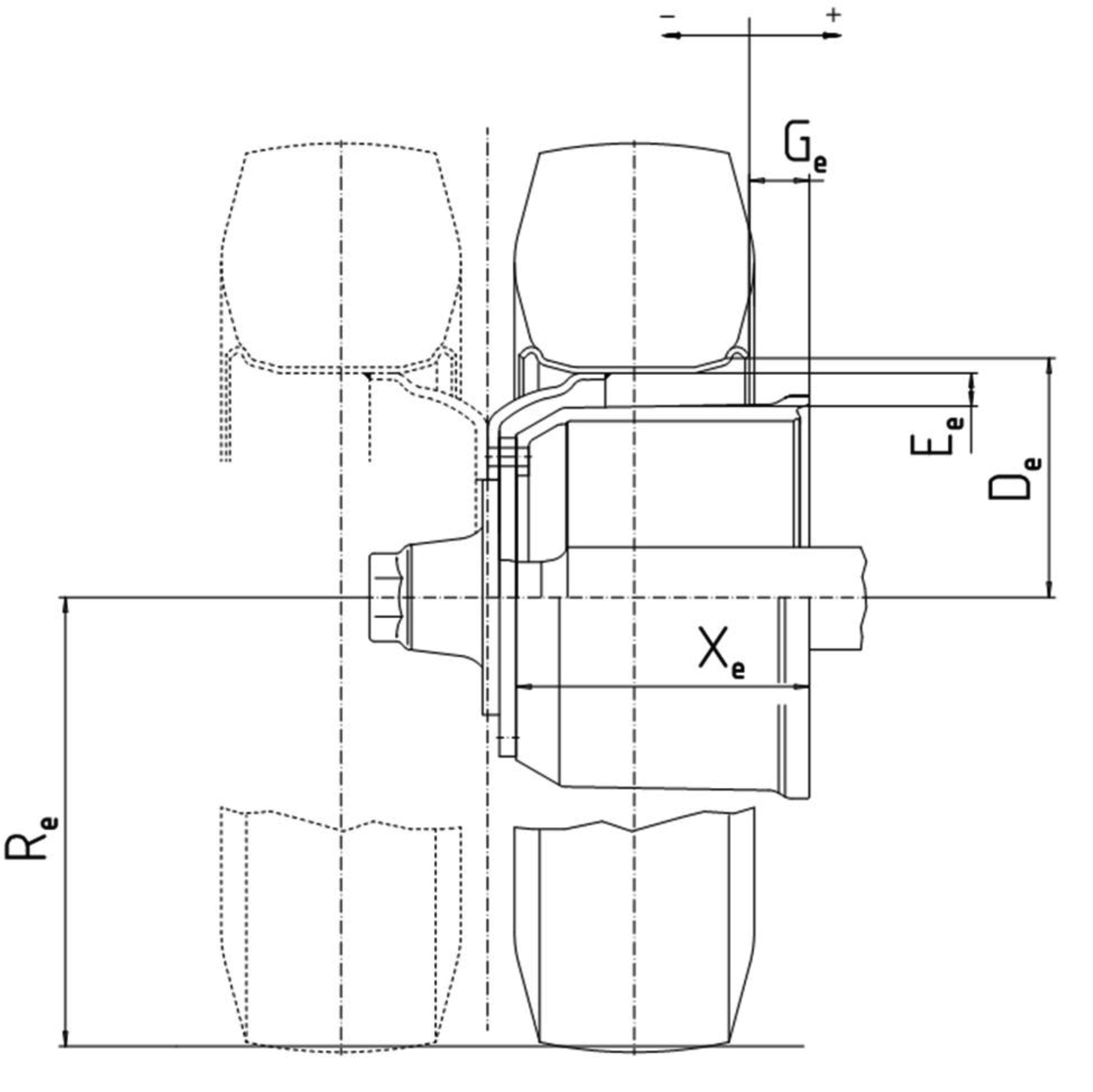


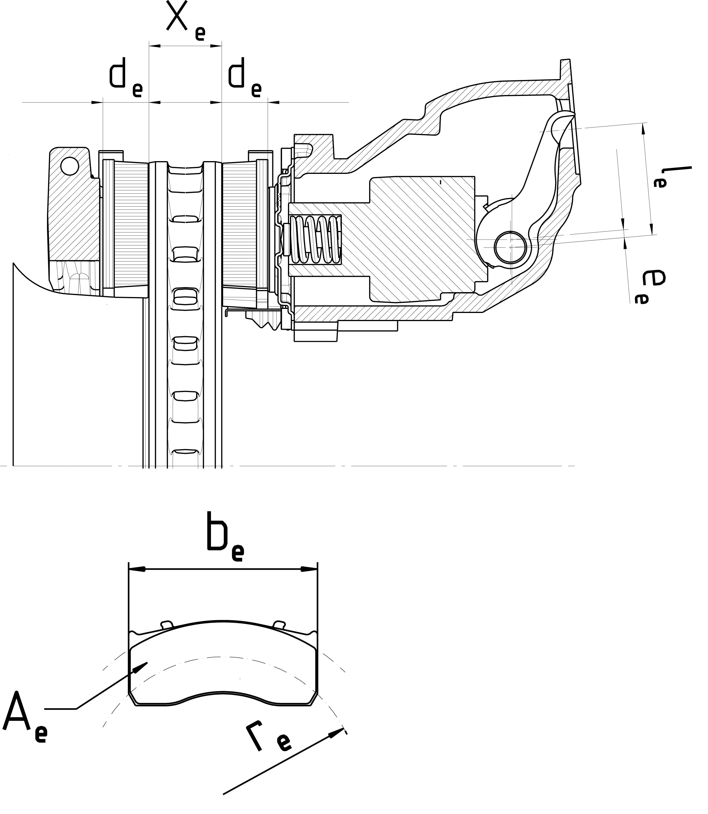
|
xe (mm) |
ae (mm) |
he (mm) |
ce (mm) |
de (mm) |
ee (mm) |
α0e |
α1e |
be (mm) |
re (mm) |
Ae (cm2) |
S1e (mm) |
S2e (mm) |
S3e (mm) |
|
|
|
|
|
|
|
|
|
|
|
|
|
|
|
E. INFORMATION ON VEHICLE CONSTRUCTION
44. CONFORMITY OF PRODUCTION
|
44.1. |
Description of overall quality-assurance management systems: … |
45. ACCESS TO VEHICLE ON BOARD DIAGNOSTIC (OBD) AND VEHICLE REPAIR AND MAINTENANCE INFORMATION (45)
|
45.1. |
Address of principal website for access to vehicle repair and maintenance information (45): … |
|
45.2. |
In the case of multi-stage type-approval, address of principal website for access to vehicle repair and maintenance information from manufacturer(s) at previous stage(s) (45): … |
|
45.3. |
Relevant information to enable the development of replacement components which are critical to the correct functioning of the OBD system provided: yes/no (4) |
|
45.4. |
Annual worldwide production of a type (61): … |
|
45.5. |
Proof(s) of compliance that vehicle repair and maintenance information is provided using only open text and graphic formats or formats which can be viewed and printed using only standard software plug-ins that are freely available, easy to install, and which run with computer operating systems commonly in use.
|
|
45.6. |
Reprogramming of control units in accordance with point 2.5 of Appendix 1 to Annex V to Commission Delegated Regulation (EU) No 1322/2014
|
|
45.7. |
Information required for the manufacture of diagnostic tools
|
|
45.8. |
Repair and maintenance information of vehicle combinations
|
46. ROLL-OVER PROTECTIVE STRUCTURE (ROPS)
|
46.1. |
Equipment of ROPS: compulsory/optional/standard (4) |
|
46.2. |
ROPS by cab/by frame/by roll bar(s) mounted at front/rear (4)
|
|
46.3. |
Photographs and detailed technical drawings showing the position of the ROPS, position of the seat index point (SIP), the details of mountings and position of the front part of the tractor capable of supporting the tractor when overturned (if necessary) etc. (in the case of front-mounted foldable ROPS, show the grasping area and a lateral and top view of the accessible zones). The main dimensions must figure on the drawings, including external dimensions of tractor with protective structure fitted and main interior dimensions: … |
|
46.4. |
Brief description of the protective structure, comprising:
|
|
46.5. |
Dimensions (52)
|
|
46.6. |
Details of materials used in the construction of the protective structure and specifications of steels used (53)
|
|
46.7. |
Alternatively to entries 46.1 to 46.6.7, provide the following information:
|
47. FALLING OBJECT PROTECTIVE STRUCTURES (FOPS)
47.1. T- and C-category vehicles equipped for forestry applications
|
47.1.1. |
Requirements under standard ISO 8083:2006 (Machinery for forestry — Falling-object protective structures (FOPS) — Laboratory tests and performance requirements) level I/level II (4) on FOPS are met with relevant documentation included in the information document: yes/no (4) |
47.2. All other T- and C-category vehicles fitted with FOPS
|
47.2.1. |
Photographs and detailed technical drawings showing the position of the FOPS, position of the seat index point (SIP), etc. The main dimensions must figure on the drawings, including external dimensions of tractor with protective structure fitted and main interior dimensions: |
|
47.2.2. |
Brief description of the protective structure, comprising:
|
|
47.2.3. |
Dimensions (52)
|
|
47.2.4. |
Details of materials used in the construction of the protective structure and specifications of steels used (53)
|
|
47.2.5. |
Details of tractor manufacturer's reinforcements on original parts: … |
|
47.2.6. |
Alternatively to entries 47.2.1 to 47.2.5, a complete test report issued on the basis of the OECD standard Code for the official testing of falling object protective structures on agricultural and forestry tractors, OECD Code 10, Edition 2015 of July 2014 is provided with relevant documentation included in the information document: yes/no (4) |
48. DRIVER'S EXPOSURE TO NOISE LEVEL
|
48.1. |
T- or C-category (with rubber tracks) vehicles to be tested in accordance with Test method 1, in accordance with point 2 of Annex XIII to Commission Delegated Regulation (EU) No 1322/2014: yes/no/not applicable (4) |
|
48.2. |
T- or C-category (with rubber tracks) vehicles to be tested in accordance with Test method 2, in accordance with point 3 of Annex XIII to Commission Delegated Regulation (EU) No 1322/2014: yes/no/not applicable (4) |
|
48.3. |
C-category vehicles with steel tracks to be tested on a layer of humid sand as specified by paragraph 5.3.2 of ISO 6395:2008 (Earth-moving machinery — Determination of sound power level — Dynamic test conditions): yes/no/not applicable (4) |
|
48.4 |
Alternatively to entries 48.1 to 48.3, a complete test report issued on the basis of the OECD standard Code for the official measurement of noise at the driving position(s) on agricultural and forestry tractors, OECD Code 5, Edition 2015 of July 2014, is provided with relevant documentation included in the information document: yes/no/not applicable (4) |
49. SEATING POSITIONS (SADDLES AND SEATS)
|
49.1. |
Seating position configuration: seat/saddle (4) |
|
49.2. |
Coordinates or drawing of the Seat Reference point(s) (S) of all seating positions: … |
|
49.3. |
Description and drawings of:
|
|
49.4. |
Driver's seat
|
|
49.5. |
Passenger seat(s)
49.5.1. Number of passenger seats: … 49.5.2. Location and arrangement (8): … 49.5.3. Dimensions of the passenger seat(s): … 49.5.4. Main characteristics of the passenger seat(s): … 49.5.5. Requirements under standard EN 15694:2009 (Agricultural and forestry tractors. Passenger seat. Requirements and test procedures) are met with relevant documentation included in the information document: yes/no/not applicable (4) 49.5.6. Requirements under standard EN 15997:2011 (All terrain vehicles (ATVs - Quads). Safety requirements and test methods) on passenger seats for ATV Type II vehicle are met with relevant documentation included in the information document: yes/no/not applicable (4) |
50. OPERATING SPACE AND ACCESS TO AND EXIT OF THE VEHICLE INCLUDING DOORS AND WINDOWS
50.1. Operating space
|
50.1.1. |
Detailed photographs or drawings, including dimensions of the operating space, indicating in particular the position of the Seat reference point (S) and the dimensions of the operating space around it, the clearance between the base of the steering wheel and the fixed parts of the tractor, the locations of the control devices, rungs and necessary handrails: … |
|
50.1.2. |
Hand-operated control devices have the minimum clearances required by point 4.5.3 of ISO 4254-1:2013 (Agricultural machinery — Safety — Part 1: General requirements) with relevant documentation included in the information document: yes/no (4) |
|
50.2. |
Access to the driving position:
|
|
50.3. |
Access to other positions than the driving position:
|
|
50.4. |
Occupant doors, latches and hinges
|
|
50.5. |
Windows and emergency exit(s)
|
51. POWER TAKE-OFF(S)
|
51.1. |
Number of power take-offs: … |
|
51.2. |
Main power take-off
51.2.1. Position: front/rear/other (4) (if other specify: …) 51.2.2. Revolutions per minute: … min–1 51.2.2.1. Ratio of power take-off revolutions to that of the engine: … 51.2.3. Optional: Power at the power take-off (PTO) at the rated speed(s) (in accordance with OECD Code 2 (57) or ISO 789-1:1990 (Agricultural tractors – Test procedures – Part 1: Power tests for power take-off))
51.2.4. Power take-off guard (description, dimensions, drawings, photographs): … |
|
51.3. |
Secondary power take-off (if any)
|
|
51.4. |
Rear power take-off
|
|
51.5. |
Front power take-off
|
52. PROTECTION OF DRIVE COMPONENTS, EXHAUST SYSTEM, GUARDS AND PROTECTIVE DEVICES
|
52.1. |
Description (including drawings, sketches or photos) of the protection devices with dimensions showing the safety distances for avoiding contact with dangerous parts and the protective devices fitted for protection on dangerous points, at least for the following components:
|
|
52.2. |
Description (including photographs and drawings, if necessary) of the protective devices employed for:
|
|
52.3. |
Requirements under standard EN 15997:2011 (All terrain vehicles (ATVs — Quads). Safety requirements and test methods) on hot surfaces are met with relevant documentation included in the information document: yes/no/not applicable (4) |
|
52.4. |
Description (including drawings, sketches or photos) of the layout and marking of flexible hydraulic hoses: … |
|
52.5. |
For R-category vehicles with tipping capability, description (including drawings, sketches or photos) of the support devices for service and maintenance: … |
|
52.6. |
Description and identification (including drawings, sketches or photos) of the greasing points and the means to access them: … |
53. SEAT-BELT ANCHORAGES
|
53.1. |
Requirements under standard ISO 3776-1:2006 (Tractors and machinery for agriculture — Seat belts — Part 1: Anchorage location requirements) are met with relevant documentation included in the information document: yes/no (4) |
|
53.2. |
Photographs and/or drawings of the bodywork showing the true, effective location and dimensions of the anchorages: … |
|
53.3. |
Drawings of the anchorages and the parts of the vehicle structure to which they are attached (together with a statement on the nature of the materials used): … |
|
53.4. |
Designation of the types of belts (14) authorised for attachment to the anchorages on the vehicles
|
|||||||||||||||||||||||||||||||||||||||||||||||
|
53.5. |
Special devices (example: seat-height adjustment, preloading device, etc.): … |
|
53.6. |
Description of a particular type of safety belt where an anchorage is located in the seat backrest or incorporates an energy dissipating device: … |
|
53.7. |
Alternative to entries 53.2 to 53.6.
|
54. SAFETY BELTS
|
54.1. |
Requirements under standard ISO 3776-3:2009 (Tractors and machinery for agriculture — Seat belts — Part 3: Requirements for assemblies) are met with relevant documentation included in the information document: yes/no (4) |
|
54.2. |
Test report granted a on the basis of UNECE Regulation No 16 (OJ L 233, 9.9.2011, p. 1) with relevant documentation included in the information document: yes/no (4) |
|
54.3. |
Number and position of safety belts and seats on which they can be used, please fill out table below:
Safety belt configuration and associated information
|
||||||||||||||||||||||||||||||||||||||||||||||||||||||
|
54.4. |
Brief description of electrical/electronic components: … |
55. PROTECTION AGAINST PENETRATING OBJECTS (OPS)
55.1. T- and C-category vehicles equipped for forestry applications
|
55.1.1. |
Requirements under ISO 8084:2003 (Machinery for forestry — Operator protective structures — Laboratory tests and performance requirements) are met with relevant documentation included in the information document: yes/no (4) |
55.2. All other T- and C-category vehicles fitted with OPS
|
55.2.1. |
Requirements under Annex 14 to UNECE Regulation 43 (OJ L 230, 31.8.2010, p. 119) on safety glazing are met with the relevant documentation included in the information document: yes/no (4) |
56. OPERATOR'S MANUAL, INFORMATION WARNINGS AND MARKINGS
56.1. Operator's manual
|
56.1.1. |
Requirements under ISO 3600:1996 (Tractors, machinery for agriculture and forestry, powered lawn and garden equipment — Operator's manuals — Content and presentation), with the exception of section 4.3 (Machine identification), are met: yes/no (4) |
|
56.1.2. |
Information requested under Annex XXII to Commission Delegated Regulation (EU) No 1322/2014 is provided in the operator's manual: yes/no (4) |
56.2. Information, warnings and markings
|
56.2.1. |
Requirements under ISO 3767 Parts 1 (1998+A2:2012) (Tractors, machinery for agriculture and forestry, powered lawn and garden equipment — Symbols for operator controls and other displays — Part 1: Common symbols) and, if applicable, Part 2 (:2008) (Tractors, machinery for agriculture and forestry, powered lawn and garden equipment — Symbols for operator controls and other displays — Part 2: Symbols for agricultural tractors and machinery) are met with relevant documentation included in the information document: yes/no/not applicable (4) |
|
56.2.2. |
Alternatively to entry 56.2.1, requirements under UNECE Regulation No 60 (OJ L 95, 31.3.2004, p. 10) are met with relevant documentation included in the information document: yes/no/not applicable (4) |
|
56.2.3. |
Requirements under ISO 11684:1995 (Tractors, machinery for agriculture and forestry, powered lawn and garden equipment — Safety signs and hazard pictorials — General principles) are met with relevant documentation included in the information document: yes/no/not applicable (4) |
|
56.2.4. |
Requirements under ISO 7010:2011 (Graphical symbols — Safety colours and safety signs — Registered safety signs) are met with relevant documentation included in the information document: yes/no/not applicable (4) |
|
56.3. |
Description, colour coding and means for the identification of flow directions of hydraulic couplings (including drawings, sketches or photos): … |
|
56.4. |
Description, colour coding and means of identification of safe jacking points (including drawings, sketches or photos): … |
57. DRIVER-OPERATED CONTROL DEVICES INCLUDING IDENTIFICATION OF CONTROL DEVICES, TELL-TALES AND INDICATORS
|
57.1. |
Photographs and/or drawings of the arrangement of symbols and controls, tell-tales and indicators: |
|
57.2. |
Controls, tell-tales and indicators for which, when fitted, identification is mandatory, and symbols to be used for that purpose
|
||||||||||||||||||||||||||||||||||||||||||||||||||||||||||||||||||||||||||||||||||||||||||||||||||||||||||||||||||||||||||||||||||||||||||||||||||||||||||||||||||||||||||||||||||||||||||||||||||||||||
|
57.3. |
Controls, tell-tales and indicators for which, when fitted, identification is optional, and symbols which shall be used if they are to be identified
|
||||||||||||||||||||||||||||||||||||||||||||||||||||||||||||||||||||||||||||||||||||||||||||||||||||||||||||||||||||||||
|
57.4. |
Brief description and schematic drawing of the locations, displacement, methods of operation and colour coding of the various control devices in the interior of the vehicle and showing for tractors without enclosed cab, how the accessibility to internal control devices from the ground has been avoided: … |
|
57.5. |
Brief description and schematic drawing of the locations, displacement, methods of operation and colour coding of the various control devices in the exterior of the vehicle and indicating the front and the rear hazard zones in accordance with Appendix 1 of Annex XXIII to Commission Delegated Regulation (EU) No 1322/2014: … |
|
57.6. |
Requirements under Annexes A and C of standard ISO 15077:2008 (Tractors and self-propelled machinery for agriculture – Operator controls – Actuating forces, displacement, location and method of operation) are met with relevant documentation included in the information document: yes/no (4) |
|
57.7. |
Requirements under paragraph 4.5.3 of standard ISO 4254-1:2013 (Agricultural machinery – Safety – Part 1: General requirements), with the exception of fingertip operation control devices, are met with relevant documentation included in the information document: yes/no (4) |
|
57.8. |
Requirements under standard EN 15997:2011 (All terrain vehicles (ATVs - Quads). Safety requirements and test methods) on throttle control and manual clutch control are met with relevant documentation included in the information document: yes/no/not applicable (4) |
|
57.9. |
For vehicles of T- and C-category, requirements under standard ISO 10975:2009 (Tractors and machinery for agriculture – Auto-guidance systems for operator-controlled tractors and self-propelled machines – Safety requirements) are met with relevant documentation included in the information document: yes/no/not applicable (4) |
58. PROTECTION AGAINST HAZARDOUS SUBSTANCES
|
58.1. |
Brief description (including drawings and photographs) of the air delivery and filtration system, including the devices to obtain a positive differential within the cab and the air flow of fresh filtered air: … |
|
58.2. |
Requirements under standard EN 15695-1 (Agricultural tractors and self-propelled sprayers — Protection of the operator (driver) against hazardous substances — Part 1: Cab classification, requirements and test procedures): category 1/category 2/category 3 category 4 (4) on cab classification with regard to protection against hazardous substances are met with relevant documentation included in the information document: yes/no (4) |
|
58.3. |
Requirements under standard EN 15695-2 (Agricultural tractors and self-propelled sprayers — Protection of the operator (driver) against hazardous substances — Part 2: Filters, requirements and test procedures): Dust filter/Aerosol filter/Vapour filter (4) on filters with regard to protection against hazardous substances are met with relevant documentation included in the information document: yes/no (4) |
59. FOR T- AND C-CATEGORY VEHICLES, MACHINERY (63) MOUNTED ON THE VEHICLE
|
59.1. |
General description of the machinery and its inter-action with the vehicle: … |
|
59.2. |
Overall drawing of the machinery and drawings of the control circuits, as well as the pertinent descriptions and explanations necessary for understanding the operation of the machinery: … |
Appendix 1
Model information document relating to EU type-approval of a type of (or a type of a vehicle with regard to) an installation of an engine/engine family system
A. GENERAL INFORMATION
2. GENERAL INFORMATION CONCERNING SYSTEMS, COMPONENTS OR SEPARATE TECHNICAL UNITS
|
2.1. |
Make(s) (trade name(s) of manufacturer): … |
|
2.2. |
Type (49): …
|
|
2.3. |
Company name and address of manufacturer: …
|
|
2.4. |
For systems and separate technical units, vehicle(s) for which they are intended for (21):
|
|
2.5. |
Additional general information for engines
|
5. GENERAL POWERTRAIN CHARACTERISTICS
5.1. Maximum vehicle speed
5.1.1. Forward maximum vehicle speed
|
5.1.1.1. |
Declared maximum design vehicle speed: … km/h |
|
5.1.1.2. |
Calculated maximum design vehicle speed in top gear (show factors used in calculation) (41): … km/h |
|
5.1.1.3. |
Measured maximum vehicle speed: … km/h (41) |
5.1.2. Rearward maximum vehicle speed (54)
|
5.1.2.1. |
Declared rearward maximum design vehicle speed: … km/h |
▼M1 —————
|
5.2. |
Rated engine net power: … kW, at … min–1 (in accordance with UNECE Regulation No 120 (OJ L 257, 30.9.2010, p. 280)) |
|
5.3. |
Maximum engine net power: … kW, at … min–1 (in accordance with UNECE Regulation No 120 (OJ L 257, 30.9.2010, p. 280)) |
|
5.4. |
Maximum engine torque: … Nm, at … min–1 (in accordance with UNECE Regulation No 120 (OJ L 257, 30.9.2010, p. 280)) |
|
5.5. |
Fuel type (9): … |
B. INFORMATION ON ENVIRONMENTAL AND PROPULSION PERFORMANCE
6. ESSENTIAL CHARACTERISTICS OF THE PARENT ENGINE/ENGINE (4)
|
6.1. |
Cycle: four stroke/two stroke (4) |
|
6.2. |
Bore (12) … mm |
|
6.3. |
Stroke (12): … mm |
|
6.4. |
Number … and layout (26) … of cylinders |
|
6.5. |
Engine capacity: … cm3 |
|
6.6. |
Rated speed: … min–1 |
|
6.7. |
Maximum torque speed: … min–1 |
|
6.8. |
Volumetric compression ratio (7): … |
|
6.9. |
Combustion system description: … |
|
6.10. |
Drawing(s) of combustion chamber and piston crown: … |
|
6.11. |
Minimum cross sectional area of inlet and outlet ports: … |
|
6.12. |
Cooling system 6.12.1. Liquid
6.12.2. Air
|
|
6.13. |
Temperature permitted by the manufacturer
|
|
6.14. |
Pressure charger
|
|
6.15. |
Intake system: maximum allowable intake depression at rated engine speed and at 100 % load: … kPa |
|
6.16. |
Exhaust system: maximum permissible exhaust backpressure at rated engine speed and at 100 % load: … kPa |
|
6.17. |
Measures taken against air pollution
|
|
6.18. |
Fuel feed for diesel engines
6.18.1. Feed pump 6.18.1.1 Pressure (7) … kPa or characteristic diagram: … 6.18.2. Injection system 6.18.2.1. Pump 6.18.2.1.1. Make(s): … 6.18.2.1.2. Type(s): … 6.18.2.1.3. Delivery: … and … mm3 (7) per stroke or cycle at full injection at pump speed of: … rpm (rated) and: … rpm (maximum torque) respectively, or characteristic diagram: … 6.18.2.1.3.1. Method used: on engine/on pump bench (4) 6.18.2.2. Injection advance: 6.18.2.2.1. Injection advance curve (7): … 6.18.2.2.2. Timing (7): … 6.18.2.3. Injection piping: 6.18.2.3.1. Length: … mm 6.18.2.3.2. Internal diameter: … mm 6.18.2.4. Injector(s) 6.18.2.4.1. Make(s) … 6.18.2.4.2. Type(s): … 6.18.2.4.3. Opening pressure (7): … kPa, or characteristic diagram: … 6.18.2.5. Governor 6.18.2.5.1. Make(s) … 6.18.2.5.2. Type(s): … 6.18.2.5.3. Speed at which cut-off starts under full load (7): … min–1 6.18.2.5.4. Maximum no-load speed (7): … min–1 6.18.2.5.5. Idling speed (7): … min–1 6.18.2.6. Cold-start system 6.18.2.6.1. Make(s): … 6.18.2.6.2. Type(s): … 6.18.2.6.3. Description: … |
|
6.19. |
Fuel for petrol engines
|
|
6.20. |
Valve timing
|
|
6.21. |
Porting configuration
|
|
6.22. |
Ignition system 6.22.1. Ignition coil
|
7. ESSENTIAL CHARACTERISTICS OF THE ENGINE FAMILY
7.1. Common parameters (56)
|
7.1.1. |
Combustion cycle: positive ignition/compression ignition (4) |
|
7.1.2. |
Cooling medium … |
|
7.1.3. |
Method of air aspiration: … |
|
7.1.4. |
Combustion chamber type and design: … |
|
7.1.5. |
Valve and porting configuration, size and number: … |
|
7.1.6. |
Fuel system: … |
|
7.1.7 |
Engine management systems (proof of identity pursuant to drawing number(s))
|
|
7.1.8 |
Exhaust after-treatment system (3): … |
7.2. Engine family listing
|
7.2.1. |
Name of engine family: … |
|
7.2.2. |
Specifications of engines within the family:
|
||||||||||||||||||||||||||||||||||||||||||||||||||||||||||||||||||||||||||||||
8. ESSENTIAL CHARACTERISTICS OF THE ENGINE TYPE WITHIN THE FAMILY
|
8.1. |
Cycle: four stroke/two stroke (4): … |
|
8.2. |
Bore (12): … mm |
|
8.3. |
Stroke (12): … mm |
|
8.4. |
Number … and layout (26) … of cylinders |
|
8.5. |
Engine capacity: … cm3 |
|
8.6. |
Rated speed: … min–1 |
|
8.7. |
Maximum torque speed: … min–1 |
|
8.8. |
Volumetric compression ratio (7): … |
|
8.9. |
Combustion system description: … |
|
8.10. |
Drawings of combustion chamber and piston crown: … |
|
8.11. |
Minimum cross sectional area of inlet and outlet ports: … |
|
8.12. |
Cooling system 8.12.1. Liquid
8.12.2. Air 8.12.2.1. Blower: yes/no (4) 8.12.2.1.1. Characteristics of the blower. … 8.12.2.1.2. Drive ratio(s) (if applicable): … |
|
8.13. |
Temperature permitted by the manufacturer
|
|
8.14. |
Pressure charger
|
|
8.15. |
Intake system: maximum allowable intake depression at rated engine speed and at 100 % load: … kPa |
|
8.16. |
Exhaust system: maximum permissible exhaust backpressure at rated engine speed and at 100 % load: … kPa |
|
8.17. |
Measures taken against air pollution
8.17.1. Device for recycling crankcase gases: yes/no (4) 8.17.2. Additional anti-pollution devices (if any): 8.17.2.1. Catalytic converter: yes/no (4) 8.17.2.1.1. Make: … 8.17.2.1.2. Type … 8.17.2.1.3. Number of catalytic converters and elements … 8.17.2.1.4. Dimensions and volume of the catalytic converter(s): … 8.17.2.1.5. Type of catalytic action … 8.17.2.1.6. Total charge of precious metals: … 8.17.2.1.7. Relative concentration: … 8.17.2.1.8. Substrate (structure and material): … 8.17.2.1.9. Cell density: … 8.17.2.1.10. Type of casing for the catalytic converter(s): … 8.17.2.1.11. Location of the catalytic converter(s) (place(s) and maximum/minimum distance(s) from engine: … 8.17.2.1.12. Normal operating range: …K 8.17.2.1.13. Consumable reagent (where appropriate) … 8.17.2.1.13.1. Type and concentration of reagent needed for catalytic action: … 8.17.2.1.13.2. Normal operational temperature range of reagent: … K 8.17.2.1.13.3. International standard (if applicable): … 8.17.2.1.14. NOx sensor: yes/no (4) 8.17.2.1.15. Oxygen sensor: yes/no (4) 8.17.2.1.15.1. Make: … 8.17.2.1.15.2. Type … 8.17.2.1.15.3. Location: … 8.17.2.1.16. Air injection: yes/no (4) 8.17.2.1.16.1. Type: pulse air/air pump/other(4) (if other specify: …) 8.17.2.1.17. EGR: yes/no (4) 8.17.2.1.17.1. Characteristics (cooled/uncooled, high pressure/low pressure, etc.): … 8.17.2.1.18. Particulate trap: yes/no (4) 8.17.2.1.18.1. Dimensions and capacity of the particulate trap: … 8.17.2.1.18.2. Type and design of the particulate trap: … 8.17.2.1.18.3. Location (place(s) and maximum/minimum distance(s) from engine: … 8.17.2.1.18.4. Method or system of regeneration, description and/or drawing: … 8.17.2.1.18.5. Normal operating temperature range: … K and pressure range: … kPa 8.17.2.1.19. Other systems: yes/no (4) 8.17.2.1.19.1. Description and operation:… |
|
8.18. |
Fuel feed for diesel engines
8.18.1. Feed pump 8.18.1.1 Pressure (7) … kPa or characteristic diagram: … 8.18.2. Injection system 8.18.2.1. Pump 8.18.2.1.1. Make(s): … 8.18.2.1.2. Type(s): … 8.18.2.1.3. Delivery: … and … mm3 (7) per stroke or cycle at full injection at pump speed of: … rpm (rated) and: … rpm (maximum torque) respectively, or characteristic diagram: … 8.18.2.1.3.1. Method used: on engine/on pump bench (4) 8.18.2.2. Injection advance: 8.18.2.2.1. Injection advance curve (7): … 8.18.2.2.2. Timing (7): … 8.18.2.3. Injection piping: 8.18.2.3.1. Length: … mm 8.18.2.3.2. Internal diameter: … mm 8.18.2.4. Injector(s) 8.18.2.4.1. Make(s) … 8.18.2.4.2. Type(s): … 8.18.2.4.3. Opening pressure (7): … kPa, or characteristic diagram: … 8.18.2.5. Governor 8.18.2.5.1. Make(s) … 8.18.2.5.2. Type(s): … 8.18.2.5.3. Speed at which cut-off starts under full load (7): … min–1 8.18.2.5.4. Maximum no-load speed (7): … min–1 8.18.2.5.5. Idling speed (7): … min–1 8.18.2.6. Cold-start system 8.18.2.6.1. Make(s): … 8.18.2.6.2. Type(s): … 8.18.2.6.3. Description: … |
|
8.19. |
Fuel feed for petrol engines
|
|
8.20. |
Valve timing
|
|
8.21. |
Porting configuration
|
|
8.22. |
Ignition system 8.22.1. Ignition coil
|
Appendix 2
Model information document relating to EU type-approval of a type of (or a type of a vehicle with regard to) an external sound level system
A. GENERAL INFORMATION
2. GENERAL INFORMATION CONCERNING SYSTEMS, COMPONENTS OR SEPARATE TECHNICAL UNITS
|
2.1. |
Make(s) (trade name(s) of manufacturer): … |
|
2.2. |
Type (49): …
|
|
2.3. |
Company name and address of manufacturer: …
|
|
2.4. |
For systems and separate technical units, vehicle(s) for which they are intended for (21):
|
|
2.5. |
Additional general information for engines
|
5. GENERAL POWERTRAIN CHARACTERISTICS
5.1. Maximum vehicle speed
5.1.1. Forward maximum vehicle speed
|
5.1.1.1. |
Declared maximum design vehicle speed: … km/h |
|
5.1.1.2. |
Calculated maximum design vehicle speed in top gear (show factors used in calculation) (41): … km/h |
|
5.1.1.3. |
Measured maximum vehicle speed: … km/h (41) |
5.1.2. Rearward maximum vehicle speed (54)
|
5.1.2.1. |
Declared rearward maximum design vehicle speed: … km/h |
▼M1 —————
|
5.2. |
Rated engine net power: … kW, at … min–1 (in accordance with UNECE Regulation No 120 (OJ L 257, 30.9.2010, p. 280)) |
|
5.3. |
Maximum engine net power: … kW, at … min–1 (in accordance with UNECE Regulation No 120 (OJ L 257, 30.9.2010, p. 280)) |
|
5.4. |
Maximum engine torque: … Nm, at … min–1 (in accordance with UNECE Regulation No 120 (OJ L 257, 30.9.2010, p. 280)) |
|
5.5. |
Fuel type (9): … |
10. EXTERNAL SOUND LEVEL
10.1. External sound level declared by the manufacturer
|
10.1.1. |
Moving: … dB(A) |
|
10.1.2 |
Stationary: … dB(A) |
|
10.1.3. |
At engine speed: … min–1 |
|
10.2. |
Brief description and schematic drawing of exhaust system (including the air intake system, the devices for noise and tailpipe emission control): |
|
10.3. |
Air-intake system
|
|
10.4. |
Exhaust system
|
|
10.5. |
Details of any non-engine related devices designed to reduce noise (if not covered by other items): |
Appendix 3
Model information document relating to EU type-approval of an engine/engine family as a component/STU
A. GENERAL INFORMATION
2. GENERAL INFORMATION CONCERNING SYSTEMS, COMPONENTS OR SEPARATE TECHNICAL UNITS
|
2.1. |
Make(s) (trade name(s) of manufacturer): … |
|
2.2. |
Type (49): …
|
|
2.3. |
Company name and address of manufacturer: …
|
|
2.4. |
For systems and separate technical units, vehicle(s) for which they are intended for (21):
|
|
2.5. |
Additional general information for engines
|
5. GENERAL POWERTRAIN CHARACTERISTICS
|
5.2. |
Rated engine net power: … kW, at … min–1 (in accordance with UNECE Regulation No 120 (OJ L 257, 30.9.2010, p. 280)) |
|
5.3. |
Maximum engine net power: … kW, at … min–1 (in accordance with UNECE Regulation No 120 (OJ L 257, 30.9.2010, p. 280)) |
|
5.4. |
Maximum engine torque: … Nm, at … min–1 (in accordance with UNECE Regulation No 120 (OJ L 257, 30.9.2010, p. 280)) |
|
5.5. |
Fuel type (9): … |
B. INFORMATION ON ENVIRONMENTAL AND PROPULSION PERFORMANCE
6. ESSENTIAL CHARACTERISTICS OF THE PARENT ENGINE/ENGINE (4)
|
6.1. |
Cycle: four stroke/two stroke (4) |
|
6.2. |
Bore (12) … mm |
|
6.3. |
Stroke (12): … mm |
|
6.4. |
Number … and layout (26) … of cylinders |
|
6.5. |
Engine capacity: … cm3 |
|
6.6. |
Rated speed: … min–1 |
|
6.7. |
Maximum torque speed: … min–1 |
|
6.8. |
Volumetric compression ratio (7): … |
|
6.9. |
Combustion system description: … |
|
6.10. |
Drawing(s) of combustion chamber and piston crown: … |
|
6.11. |
Minimum cross sectional area of inlet and outlet ports: … |
|
6.12. |
Cooling system
6.12.1. Liquid
6.12.2. Air
|
|
6.13. |
Temperature permitted by the manufacturer
|
|
6.14. |
Pressure charger
|
|
6.15. |
Intake system: maximum allowable intake depression at rated engine speed and at 100 % load: … kPa |
|
6.16. |
Exhaust system: maximum permissible exhaust backpressure at rated engine speed and at 100 % load: … kPa |
|
6.17. |
Measures taken against air pollution
|
|
6.18. |
Fuel feed for diesel engines
6.18.1. Feed pump 6.18.1.1 Pressure (7) … kPa or characteristic diagram: … 6.18.2. Injection system 6.18.2.1. Pump 6.18.2.1.1. Make(s): … 6.18.2.1.2. Type(s): … 6.18.2.1.3. Delivery: … and … mm3 (7) per stroke or cycle at full injection at pump speed of: … rpm (rated) and: … rpm (maximum torque) respectively, or characteristic diagram: … 6.18.2.1.3.1. Method used: on engine/on pump bench (4) 6.18.2.2. Injection advance: 6.18.2.2.1. Injection advance curve (7): … 6.18.2.2.2. Timing (7): … 6.18.2.3. Injection piping: 6.18.2.3.1. Length: … mm 6.18.2.3.2. Internal diameter: … mm 6.18.2.4. Injector(s) 6.18.2.4.1. Make(s) … 6.18.2.4.2. Type(s): … 6.18.2.4.3. Opening pressure (7): … kPa, or characteristic diagram: … 6.18.2.5. Governor 6.18.2.5.1. Make(s) … 6.18.2.5.2. Type(s): … 6.18.2.5.3. Speed at which cut-off starts under full load (7): … min–1 6.18.2.5.4. Maximum no-load speed (7): … min–1 6.18.2.5.5. Idling speed (7): … min–1 6.18.2.6. Cold-start system 6.18.2.6.1. Make(s): … 6.18.2.6.2. Type(s): … 6.18.2.6.3. Description: … |
|
6.19. |
Fuel for petrol engines
|
|
6.20. |
Valve timing
|
|
6.21. |
Porting configuration
|
|
6.22. |
Ignition system
6.22.1. Ignition coil
|
7. ESSENTIAL CHARACTERISTICS OF THE ENGINE FAMILY
7.1. Common parameters (56)
|
7.1.1. |
Combustion cycle: positive ignition/compression ignition (4) … |
|
7.1.2. |
Cooling medium … |
|
7.1.3. |
Method of air aspiration: … |
|
7.1.4. |
Combustion chamber type and design: … |
|
7.1.5. |
Valve and porting configuration, size and number: … |
|
7.1.6. |
Fuel system: … |
|
7.1.7 |
Engine management systems (proof of identity pursuant to drawing number(s))
|
|
7.1.8 |
Exhaust after-treatment system (3): … |
7.2. Engine family listing
|
7.2.1. |
Name of engine family: … |
|
7.2.2. |
Specifications of engines within the family:
|
||||||||||||||||||||||||||||||||||||||||||||||||||||||||||||||||||||||||||||||
8. ESSENTIAL CHARACTERISTICS OF THE ENGINE TYPE WITHIN THE FAMILY
|
8.1. |
Cycle: four stroke/two stroke (4): … |
|
8.2. |
Bore (12): … mm |
|
8.3. |
Stroke (12): … mm |
|
8.4. |
Number … and layout (26) … of cylinders |
|
8.5. |
Engine capacity: … cm3 |
|
8.6. |
Rated speed: … min–1 |
|
8.7. |
Maximum torque speed: … min–1 |
|
8.8. |
Volumetric compression ratio (7): … |
|
8.9. |
Combustion system description: … |
|
8.10. |
Drawings of combustion chamber and piston crown: … |
|
8.11. |
Minimum cross sectional area of inlet and outlet ports: … |
|
8.12. |
Cooling system
8.12.1. Liquid
8.12.2. Air 8.12.2.1. Blower: yes/no (4) 8.12.2.1.1. Characteristics of the blower. … 8.12.2.1.2. Drive ratio(s) (if applicable): … |
|
8.13. |
Temperature permitted by the manufacturer
|
|
8.14. |
Pressure charger
|
|
8.15. |
Intake system: maximum allowable intake depression at rated engine speed and at 100 % load: … kPa |
|
8.16. |
Exhaust system: maximum permissible exhaust backpressure at rated engine speed and at 100 % load: … kPa |
|
8.17. |
Measures taken against air pollution
8.17.1. Device for recycling crankcase gases: yes/no (4) 8.17.2. Additional anti-pollution devices (if any): 8.17.2.1. Catalytic converter: yes/no (4) 8.17.2.1.1. Make: … 8.17.2.1.2. Type … 8.17.2.1.3. Number of catalytic converters and elements … 8.17.2.1.4. Dimensions and volume of the catalytic converter(s): … 8.17.2.1.5. Type of catalytic action … 8.17.2.1.6. Total charge of precious metals: … 8.17.2.1.7. Relative concentration: … 8.17.2.1.8. Substrate (structure and material): … 8.17.2.1.9. Cell density: … 8.17.2.1.10. Type of casing for the catalytic converter(s): … 8.17.2.1.11. Location of the catalytic converter(s) (place(s) and maximum/minimum distance(s) from engine: … 8.17.2.1.12. Normal operating range: …K 8.17.2.1.13. Consumable reagent (where appropriate) … 8.17.2.1.13.1. Type and concentration of reagent needed for catalytic action: … 8.17.2.1.13.2. Normal operational temperature range of reagent: … K 8.17.2.1.13.3. International standard (if applicable): … 8.17.2.1.14. NOx sensor: yes/no (4) 8.17.2.1.15. Oxygen sensor: yes/no (4) 8.17.2.1.15.1. Make: … 8.17.2.1.15.2. Type … 8.17.2.1.15.3. Location: … 8.17.2.1.16. Air injection: yes/no (4) 8.17.2.1.16.1. Type: pulse air/air pump/other (4) (if other specify: …) 8.17.2.1.17. EGR: yes/no(4) 8.17.2.1.17.1. Characteristics (cooled/uncooled, high pressure/low pressure, etc.): … 8.17.2.1.18. Particulate trap: yes/no (4) 8.17.2.1.18.1. Dimensions and capacity of the particulate trap: … 8.17.2.1.18.2. Type and design of the particulate trap: … 8.17.2.1.18.3. Location (place(s) and maximum/minimum distance(s) from engine: … 8.17.2.1.18.4. Method or system of regeneration, description and/or drawing: … 8.17.2.1.18.5. Normal operating temperature range: … K and pressure range: …kPa 8.17.2.1.19. Other systems: yes/no (4) 8.17.2.1.19.1. Description and operation: … |
|
8.18. |
Fuel feed for diesel engines
8.18.1. Feed pump 8.18.1.1 Pressure (7) … kPa or characteristic diagram: … 8.18.2. Injection system 8.18.2.1. Pump 8.18.2.1.1. Make(s): … 8.18.2.1.2. Type(s): … 8.18.2.1.3. Delivery: … and … mm3 (7) per stroke or cycle at full injection at pump speed of: … rpm (rated) and: … rpm (maximum torque) respectively, or characteristic diagram: … 8.18.2.1.3.1. Method used: on engine/on pump bench (4) 8.18.2.2. Injection advance: 8.18.2.2.1. Injection advance curve (7): … 8.18.2.2.2. Timing (7): … 8.18.2.3. Injection piping: 8.18.2.3.1. Length: … mm 8.18.2.3.2. Internal diameter: … mm 8.18.2.4. Injector(s) 8.18.2.4.1. Make(s) … 8.18.2.4.2. Type(s): … 8.18.2.4.3. Opening pressure (7): … kPa, or characteristic diagram: … 8.18.2.5. Governor 8.18.2.5.1. Make(s) … 8.18.2.5.2. Type(s): … 8.18.2.5.3. Speed at which cut-off starts under full load (7): … min–1 8.18.2.5.4. Maximum no-load speed (7): … min–1 8.18.2.5.5. Idling speed (7): … min–1 8.18.2.6. Cold-start system 8.18.2.6.1. Make(s): … 8.18.2.6.2. Type(s): … 8.18.2.6.3. Description: … |
|
8.19. |
Fuel feed for petrol engines
|
|
8.20. |
Valve timing
|
|
8.21. |
Porting configuration
|
|
8.22. |
Ignition system
8.22.1. Ignition coil
|
Appendix 4
Model information document relating to EU type-approval of a type of (or a type of a vehicle with regard to) a driver information system
A. GENERAL INFORMATION
2. GENERAL INFORMATION CONCERNING SYSTEMS, COMPONENTS OR SEPARATE TECHNICAL UNITS
|
2.1. |
Make(s) (trade name(s) of manufacturer): … |
|
2.2. |
Type (49): …
|
|
2.3. |
Company name and address of manufacturer: …
|
|
2.4. |
For systems and separate technical units, vehicle(s) for which they are intended for (21):
|
20. DRIVER INFORMATION SYSTEMS
|
20.1. |
Requirements under ISO 15077:2008 (Tractors and self-propelled machinery for agriculture — Operator controls — Actuating forces, displacement, location and method of operation) Annex B on operator controls associated with virtual terminals are met with relevant documentation included in the information document: yes/no (4) |
Appendix 5
Model information document relating to EU type-approval of a type of (or a type of a vehicle with regard to) an installation of lighting and light-signalling devices system
A. GENERAL INFORMATION
2. GENERAL INFORMATION CONCERNING SYSTEMS, COMPONENTS OR SEPARATE TECHNICAL UNITS
|
2.1. |
Make(s) (trade name(s) of manufacturer): … |
|
2.2. |
Type (49): …
|
|
2.3. |
Company name and address of manufacturer: …
|
|
2.4. |
For systems and separate technical units, vehicle(s) for which they are intended for (21):
|
3. GENERAL CONSTRUCTION CHARACTERISTICS
|
3.1. |
Photographs or drawings of a representative version of the vehicle: … |
|
3.2. |
Scale and dimensioned drawing of the whole vehicle: … |
21. INSTALLATION OF LIGHTING, LIGHT-SIGNALLING DEVICES, INCLUDING AUTOMATIC SWITCHING OF LIGHTING
|
21.1. |
List of all devices (mentioning the number, make(s),type, component type-approval mark(s), the maximum intensity of the main-beam headlamps, colour, the corresponding tell-tale); the list may include several types of device for each function; in addition, the list may include in respect of each function the additional annotation ‘or equivalent devices’: … |
|
21.2. |
A diagram of the lighting and signalling installation as a whole, showing the position of the various devices on the vehicle: … |
|
21.3. |
Dimensioned sketches of the exterior of the vehicle showing the location of the lighting and light-signalling devices, number and colour of lights: … |
|
21.4. |
For every lamp and reflector, supply the following information:
|
|
21.5. |
Description/drawing and type of headlamp levelling device (e.g. automatic, stepwise manually adjustable, continuously manually adjustable) (4): …
|
|
21.6. |
For R- and S-category vehicles, description of the power connection for lighting and light-signalling devices: … |
|
21.7. |
Brief description of the electrical and/or electronic components used in the lighting system and in the light-signalling system: … |
Appendix 6
Model information document relating to EU type-approval of a type of (or a type of a vehicle with regard to) an electro-magnetic compatibility system
A. GENERAL INFORMATION
2. GENERAL INFORMATION CONCERNING SYSTEMS, COMPONENTS OR SEPARATE TECHNICAL UNITS
|
2.1. |
Make(s) (trade name(s) of manufacturer): … |
|
2.2. |
Type (49): …
|
|
2.3. |
Company name and address of manufacturer: …
|
|
2.4. |
For systems and separate technical units, vehicle(s) for which they are intended for (21):
|
24. ELECTRO-MAGNETIC COMPATIBILITY (EMC)
|
24.1. |
Schedule describing all projected combinations of relevant vehicle electrical/electronic systems or ESAs, body styles (60), variations in body material, general wiring arrangements, engine variations, left-hand/right-hand drive versions and wheelbase versions: … |
|
24.2. |
Requirements under UNECE Regulation No 10 (OJ L 254, 20.9.2012, p. 1) are met with the relevant documentation included in the information document: yes/no (4) |
|
24.3. |
Requirements under ISO 14982:1998 (Agricultural and forestry machinery — Electromagnetic compatibility — Test methods and acceptance criteria) are met with relevant documentation included in the information document: yes/no (4) |
|
24.4. |
Alternatively to entry 24.2 or entry 24.3, provide the following information: 24.4.1. Description and drawings/photographs of the shapes and constituent materials of the part of the body forming the engine compartment and adjacent parts of the passenger compartment: … 24.4.2. Drawings or photographs of the position of the metal components housed in the engine compartment (e.g. heating appliances, spare wheel, air filter, steering mechanism, etc.): … 24.4.3. Table or drawing of radio-interference control equipment: … 24.4.4. Particulars of the nominal value of the direct-current resistance, and, in the case of resistive ignition cables, of their nominal resistance per metre: … |
Appendix 7
Model information document relating to EU type-approval of a type of (or a type of a vehicle with regard to) an installation of audible warning device(s) system
A. GENERAL INFORMATION
2. GENERAL INFORMATION CONCERNING SYSTEMS, COMPONENTS OR SEPARATE TECHNICAL UNITS
|
2.1. |
Make(s) (trade name(s) of manufacturer): … |
|
2.2. |
Type (49): …
|
|
2.3. |
Company name and address of manufacturer: …
|
|
2.4. |
For systems and separate technical units, vehicle(s) for which they are intended for (21):
|
25. AUDIBLE WARNING DEVICE(S)
|
25.1. |
Component type-approval for an audible warning device granted according to the requirements for N-category vehicles in the UNECE Regulation No 28 (OJ L 323, 6.12.2011, p. 33), with relevant documentation included in the information document: yes/no (4) |
|
25.2. |
Summary description of device(s) used: … |
|
25.3. |
Drawing(s) showing the location of the audible warning device(s) in relation to the structure of the vehicle: … |
|
25.4. |
Details of the method of attachment, including the part of the vehicle structure to which the audible warning device(s) is (are) attached: … |
|
25.5. |
Electrical/pneumatic circuit diagram: …
|
|
25.6. |
Drawing of the mounting device: … |
Appendix 8
Model information document relating to EU type-approval of a type of (or a type of a vehicle with regard to) the installation of rear-view mirrors as a system
A. GENERAL INFORMATION
2. GENERAL INFORMATION CONCERNING SYSTEMS, COMPONENTS OR SEPARATE TECHNICAL UNITS
|
2.1. |
Make(s) (trade name(s) of manufacturer): … |
|
2.2. |
Type (49): …
|
|
2.3. |
Company name and address of manufacturer: …
|
|
2.4. |
For systems and separate technical units, vehicle(s) for which they are intended for (21):
|
18. REAR-VIEW MIRRORS
|
18.1. |
Number and class(es) of the mirrors: … |
|
18.2. |
Requirements under UNECE Regulation No 46 (OJ L 177, 10.7.2010, p. 211) are met with the relevant documentation included in the information document: yes/no/not applicable (4) |
|
18.3. |
Requirements under UNECE Regulation No 81 (OJ L 185, 13.7.2012, p. 1) are met with the relevant documentation included in the information document: yes/no/not applicable (4) |
|
18.4. |
Drawing(s) for the identification of the mirror showing the position of the mirror relative to the vehicle structure: … |
|
18.5. |
Details of the method of attachment including that part of the vehicle structure to which it is attached: … |
|
18.6. |
Brief description of the electrical/electronic components of the adjustment system: … |
|
18.7 |
Technical description of the defrosting and demisting system of the mirrors: … |
|
18.8. |
Optional equipment that might restrict the field of vision to the rear: … |
|
18.9. |
Field of vision for rear view mirror(s) of class II
|
19. DEVICES FOR INDIRECT VISION OTHER THAN MIRRORS (OPTIONAL)
|
19.1. |
Type and characteristics (such as a complete description of the device): … |
|
19.2. |
In the case of a camera-monitor device, the detection distance (mm), contrast, luminance range, glare correction, display performance (black and white/colour (4)), image repetition frequency, luminance reach of the monitor (4): … |
|
19.3. |
Sufficiently detailed drawings to identify the complete device, including installation instructions: … |
|
19.4. |
Requirements under ISO 5721-2:2014 (Agricultural tractors — Requirements, test procedures and acceptance criteria for the operators field of vision — Part 2: Field of vision to the side and to the rear) are met with relevant documentation included in the information document: yes/no (4) |
Appendix 9
Model information document relating to EU type-approval of a type of (or a type of a vehicle with regard to) an installation of a crawler undercarriage system
A. GENERAL INFORMATION
2. GENERAL INFORMATION CONCERNING SYSTEMS, COMPONENTS OR SEPARATE TECHNICAL UNITS
|
2.1. |
Make(s) (trade name(s) of manufacturer): … |
|
2.2. |
Type (49): …
|
|
2.3. |
Company name and address of manufacturer: …
|
|
2.4. |
For systems and separate technical units, vehicle(s) for which they are intended for (21):
|
3. GENERAL CONSTRUCTION CHARACTERISTICS
|
3.1. |
Photographs or drawings of a representative version of the vehicle: … |
|
3.2. |
Scale and dimensioned drawing of the whole vehicle: … |
|
3.3. |
Axles and wheels:
|
|
3.4. |
For C-category vehicles
|
|
3.5. |
Chassis
|
4. MASSES AND DIMENSIONS
(in kg and mm) (Refer to drawings where applicable)
4.1 Range of vehicle mass (overall)
4.1.1. Unladen mass
|
4.1.1.1. |
Unladen mass(es) in running order (13):
|
4.1.2. Maximum mass(es), as declared by the manufacturer
|
4.1.2.1. |
Technically permissible maximum laden mass(es) of the vehicle (13): … kg
|
▼M1 —————
|
4.1.2.3. |
Mass(es) and crawler undercarriage
|
||||||||||||||||||||||||||||||||||||||||||
▼M1 —————
|
4.1.3. |
Technically permissible towable mass(es) for T- or C-category vehicles for each chassis/ braking configuration of the R- or S-category vehicle (for R- and S-category vehicles, indicate the maximum permissible load(s) on the rear coupling point):
|
||||||||||||||||||||||||
|
4.1.4. |
Total technically permissible mass(es) of the tractor (T- or C-category vehicle) and towed vehicle (R- or S-category vehicle) combination for each chassis/braking configuration of the R- or S-category vehicle:
|
▼M1 —————
37. CRAWLER UNDERCARRIAGE
(provide also entry 4.1.2.3)
|
37.1. |
Photographs and dimensioned drawings of the arrangement of the crawler undercarriage and its installation on the vehicle (including the elements inside of track belts to ensure that the track belt is guided over the rollers and the track pattern in the outside): … |
|
37.2. |
Type of material in contact with the surface: rubber tracks/steel tracks/rubber pads on the track shoes (4) |
|
37.3. |
Metallic tracks
|
|
37.4. |
Rubber tracks
|
Appendix 10
Model information document relating to EU type-approval of electro-magnetic compatibility of electrical/electronic sub-assemblies as a STU
A. GENERAL INFORMATION
2. GENERAL INFORMATION CONCERNING SYSTEMS, COMPONENTS OR SEPARATE TECHNICAL UNITS
|
2.1. |
Make(s) (trade name(s) of manufacturer): … |
|
2.2. |
Type (49): …
|
|
2.3. |
Company name and address of manufacturer: …
|
|
2.4. |
For systems and separate technical units, vehicle(s) for which they are intended for (21):
|
24. ELECTRO-MAGNETIC COMPATIBILITY (EMC)
|
24.1. |
Schedule describing all projected combinations of relevant vehicle electrical/electronic systems or ESAs, body styles (60), variations in body material, general wiring arrangements, engine variations, left-hand/right-hand drive versions and wheelbase versions:… |
|
24.2. |
Requirements under UNECE Regulation No 10 (OJ L 254, 20.9.2012, p. 1) are met with the relevant documentation included in the information document: yes/no (4) |
|
24.3. |
Requirements under ISO 14982:1998 (Agricultural and forestry machinery — Electromagnetic compatibility — Test methods and acceptance criteria) are met with relevant documentation included in the information document: yes/no (4) |
|
24.4. |
Alternatively to entry 24.2 or entry 24.3, provide the following information: 24.4.1. Description and drawings/photographs of the shapes and constituent materials of the part of the body forming the engine compartment and adjacent parts of the passenger compartment: … 24.4.2. Drawings or photographs of the position of the metal components housed in the engine compartment (e.g. heating appliances, spare wheel, air filter, steering mechanism, etc.): … 24.4.3. Table or drawing of radio-interference control equipment: … 24.4.4. Particulars of the nominal value of the direct-current resistance, and, in the case of resistive ignition cables, of their nominal resistance per metre: … |
Appendix 11
Model information document relating to EU type-approval of ballast masses as a component/STU
A. GENERAL INFORMATION
2. GENERAL INFORMATION CONCERNING SYSTEMS, COMPONENTS OR SEPARATE TECHNICAL UNITS
|
2.1. |
Make(s) (trade name(s) of manufacturer): … |
|
2.2. |
Type (49): …
|
|
2.3. |
Company name and address of manufacturer: …
|
|
2.4. |
For systems and separate technical units, vehicle(s) for which they are intended for (21):
|
29. BALLAST MASSES
29.1. Detailed technical description (including photographs or drawings with dimensions) of the ballast masses and how they are mounted on the tractor:
29.2. Number of sets of ballast masses: …
29.2.1. Number of components on each set: Set 1: … Set 2:… Set …:…
29.3. Mass of the components on each set: Set 1: ….kg Set 2: …kg Set … kg
29.3.1. Total mass of each set: Set 1: …kg … Set 2: … kg Set … kg
29.4. Total mass of ballast masses: …kg
29.4.1. Distribution of these masses among the axles: … kg
29.5. Material(s) and method of construction: …
Appendix 12
Model information document relating to EU type-approval of a lateral and/or rear protective structure as a component/STU
A. GENERAL INFORMATION
2. GENERAL INFORMATION CONCERNING SYSTEMS, COMPONENTS OR SEPARATE TECHNICAL UNITS
|
2.1. |
Make(s) (trade name(s) of manufacturer): … |
|
2.2. |
Type (49): …
|
|
2.3. |
Company name and address of manufacturer: …
|
|
2.4. |
For systems and separate technical units, vehicle(s) for which they are intended for (21):
|
32. LATERAL AND REAR PROTECTION
32.1. Lateral protection
|
32.1.5. |
In the case of lateral protection device(s), full description and/or drawing of such device(s) (including mountings and fittings): …
|
|
32.1.6. |
Requirements under points 2 and 3 and Parts I, II and III of UNECE Regulation No 73 (OJ L 122, 8.5.2012, p. 1) are met with relevant documentation included in the information document: yes/no (4) |
32.2. Rear protective structure
|
32.2.4. |
In case of a special device, full description and/or drawing of the rear protective structure (including mountings and fittings), or, if approved as separate technical unit, type-approval number: … |
|
32.2.4.1. |
Materials used: … |
|
32.2.4.2. |
Complete details of fittings required and full instructions, including torque requirements, for fitting: … |
Appendix 13
Model information document relating to EU type-approval of a tyre as a component
A. GENERAL INFORMATION
2. GENERAL INFORMATION CONCERNING SYSTEMS, COMPONENTS OR SEPARATE TECHNICAL UNITS
|
2.1. |
Make(s) (trade name(s) of manufacturer): … |
|
2.2. |
Type (49): …
|
|
2.3. |
Company name and address of manufacturer: …
|
35. TYRES
|
35.8. |
Tyre size designation: … |
|
35.9. |
Type of vehicle(s) for which is intended for: tractor (T- and C-category vehicles)/trailer (R-category vehicles)/interchangeable towed equipment (S-category vehicles) (4) |
|
35.10. |
Tyre construction: diagonal (bias-ply)/bias belted/radial for construction applications (4) |
|
35.11. |
Photographs and drawing of the mould's sidewall: … |
|
35.12. |
Load capacity index and speed category symbol …
|
|
35.13. |
Rolling resistance in accordance with ISO 28580:2009 (Passenger car, truck and bus tyres — Methods of measuring rolling resistance — Single point test and correlation of measurement results) (where applicable): … |
|
35.14. |
Service for which is intended: drive wheel/free rolling wheel/both (4) |
|
35.15. |
Tyre designed for use without an inner tube (tubeless): yes/no (4) |
|
35.16. |
Inflation pressure for bead seating during tyre mounting less than: … kPa. |
Appendix 14
Model information document relating to EU type-approval of a mechanical coupling as a component/STU
A. GENERAL INFORMATION
2. GENERAL INFORMATION CONCERNING SYSTEMS, COMPONENTS OR SEPARATE TECHNICAL UNITS
|
2.1. |
Make(s) (trade name(s) of manufacturer): … |
|
2.2. |
Type (49): …
|
|
2.3. |
Company name and address of manufacturer: …
|
|
2.4. |
For systems and separate technical units, vehicle(s) for which they are intended for (21):
|
38. MECHANICAL COUPLINGS
|
38.1. |
Photographs and dimensional drawings of the mechanical coupling, its installation on the vehicle and its coupling with the device installed on the towed vehicle: …
|
|
38.2. |
Short technical description of the mechanical coupling specifying the type of construction and the material used |
|
38.5. |
Description of the mechanical coupling:
|
|
38.6. |
Component type-approval for a mechanical coupling granted under UNECE Regulation No 55 (OJ L 227, 28.8.2010, p. 1), with relevant documentation included in the information document: yes/no/not applicable (4) |
Appendix 15
Model information document relating to EU type-approval of a type of (or a type of a vehicle with regard to) a braking system
A. GENERAL INFORMATION
2. GENERAL INFORMATION CONCERNING SYSTEMS, COMPONENTS OR SEPARATE TECHNICAL UNITS
|
2.1. |
Make(s) (trade name(s) of manufacturer): … |
|
2.2. |
Type (49): …
|
|
2.3. |
Company name and address of manufacturer: …
|
|
2.4. |
For systems and separate technical units, vehicle(s) for which they are intended for (21):
|
3. GENERAL CONSTRUCTION CHARACTERISTICS
|
3.1. |
Photographs or drawings of a representative version of the vehicle: … |
|
3.2. |
Scale and dimensioned drawing of the whole vehicle: … |
|
3.3. |
Axles and wheels:
|
|
3.4. |
For C-category vehicles
|
|
3.5. |
Chassis
|
|
3.12. |
For R- and S-category vehicles, type of braking: unbraked/inertia-braked/continuous braked/semi-continuous braked/hydraulic braked/pneumatic braked (4) |
4. MASSES AND DIMENSIONS
(in kg and mm) (Refer to drawings where applicable)
4.1 Range of vehicle mass (overall)
4.1.1. Unladen mass
|
4.1.1.1. |
Unladen mass(es) in running order (13):
|
4.1.2. Maximum mass(es), as declared by the manufacturer
|
4.1.2.1. |
Technically permissible maximum laden mass(es) of the vehicle (13): … kg
|
▼M1 —————
|
4.1.3. |
Technically permissible towable mass(es) for T- or C-category vehicles for each chassis/ braking configuration of the R- or S-category vehicle (for R- and S-category vehicles, indicate the maximum permissible load(s) on the rear coupling point):
|
||||||||||||||||||||||||
|
4.1.4. |
Total technically permissible mass(es) of the tractor (T- or C-category vehicle) and towed vehicle (R- or S-category vehicle) combination for each chassis/braking configuration of the R- or S-category vehicle:
|
▼M1 —————
4.2. Range of vehicle dimensions (overall)
|
4.2.2.5. |
Wheelbase (37): … mm |
|
4.2.2.6. |
Distance(s) between consecutive axles 1-2: … mm 2-3: … mm, 3-4: … mm, etc. |
|
4.2.2.7. |
For rigid draw bar and centre axle R- and S-category vehicles:
|
|
4.2.2.8. |
Maximum and minimum width of track of each axle (measured between the symmetry planes of the single or twin tyres or of the tyres in triple formation normally fitted) (to be stated by the manufacturer) (38): 4.2.2.8.1. Maximum: Axle 1 … mm Axle 2 … mm Axle …: … mm 4.2.2.8.2. Minimum: Axle 1 … mm Axle 2 … mm Axle …: … mm |
|
4.2.2.9. |
Position of centre of gravity of the vehicle in the longitudinal, transverse and vertical direction: …
|
5. GENERAL POWERTRAIN CHARACTERISTICS
5.1. Maximum vehicle speed
5.1.1. Forward maximum vehicle speed
|
5.1.1.1. |
Declared maximum design vehicle speed: … km/h |
|
5.1.1.2. |
Calculated maximum design vehicle speed in top gear (show factors used in calculation) (41): … km/h |
|
5.1.1.3. |
Measured maximum vehicle speed: … km/h (41) |
5.1.2. Rearward maximum vehicle speed (54)
|
5.1.2.1. |
Declared rearward maximum design vehicle speed: … km/h |
▼M1 —————
|
5.2. |
Rated engine net power: … kW, at … min–1 (in accordance with UNECE Regulation No 120 (OJ L 257, 30.9.2010, p. 280)) |
|
5.3. |
Maximum engine net power: … kW, at … min–1 (in accordance with UNECE Regulation No 120 (OJ L 257, 30.9.2010, p. 280)) |
|
5.4. |
Maximum engine torque: … Nm, at … min–1 (in accordance with UNECE Regulation No 120 (OJ L 257, 30.9.2010, p. 280)) |
B. INFORMATION ON ENVIRONMENTAL AND PROPULSION PERFORMANCE
6. ESSENTIAL CHARACTERISTICS OF THE PARENT ENGINE/ENGINE (4)
|
6.1. |
Cycle: four stroke/two stroke (4) |
|
6.2. |
Bore (12) … mm |
|
6.3. |
Stroke (12): … mm |
|
6.4. |
Number … and layout (26) … of cylinders |
|
6.5. |
Engine capacity: … cm3 |
|
6.6. |
Rated speed: … min–1 |
|
6.7. |
Maximum torque speed: … min–1 |
7. ESSENTIAL CHARACTERISTICS OF THE ENGINE FAMILY
7.1. Common parameters (56)
7.1.1. Combustion cycle: positive ignition/compression ignition (4)
9. ENERGY STORAGE DEVICE(S) (11)
9.1. Description: battery/capacitor/flywheel/generator (4)
9.2. Identification number: …
9.3. Kind of electrochemical couple: …
9.4. Energy stored
9.4.1. For battery, voltage: … and capacity: … Ah in 2h
9.4.2. For capacitor: … J
9.4.3. For flywheel/generator(4): … J
9.4.3.1. Flywheel moment of inertia: … kg m2
9.4.3.1.1. Additional moment of inertia if no gear is engaged: … kg m2
9.5. Charger: on-board/external/without (4)
11. DRIVE-TRAIN AND CONTROL (13)
11.1. Brief description and schematic drawing of the vehicle drive-train and its control system (gear shift control, clutch control or any other element of drive-train):
11.2. Transmission
11.2.1. Brief description and schematic drawing of gear shift system(s) and its control: …
11.2.2. Diagram and or drawing of the transmission system: …
11.2.3. Type of transmission: mechanical/hydraulic/electric/other (4) (if other specify …)
11.2.4. Brief description of the electrical/electronic components (if any): …
11.2.5. Location relative to the engine: …
11.2.6. Method of control: …
11.2.7. Transfer box: with/without (4)
11.2.8. Type of gear shift system(s) (24): …
11.3. Clutch (if any)
11.3.1. Brief description and schematic drawing of the clutch and its control system:
11.3.2. Maximum torque conversion: …
11.4. Gear ratios
|
Gear |
Internal gearbox ratios (ratios of engine to gearbox output shaft revolutions) |
Internal transfer box ratios (ratios of engine to transfer box output shaft revolutions) |
Final drive ratio(s) (ratio of gearbox output shaft to driven wheel revolutions) |
Total gear ratios |
Ratio (engine speed/vehicle speed) for manual transmission only |
|
Maximum for CVT (1) 1 2 3 |
|
|
|
|
|
|
Minimum for CVT (1) Reverse 1 … |
|
|
|
|
|
|
(*1) Continuously variable transmission |
|||||
11.5. Differential lock
11.5.1. Differential lock: yes/no/optional (4)
41. SUSPENSION
|
41.1. |
Brief description and schematic drawing of suspension and its control system for of each axle or group of axles or wheel: … |
|
41.2. |
Drawing of the suspension arrangements: … |
|
41.3. |
Level adjustment: yes/no/optional (4) |
|
41.4. |
Brief description of the electrical/electronic components: … |
|
41.5. |
Air-suspension for driving axle(s): yes/no (4)
|
|
41.6. |
Air-suspension for non-driving axle(s): yes/no (4)
|
|
41.7. |
Characteristics of the springing parts of the suspension (design, characteristics of the materials and dimensions): … |
|
41.8. |
Vehicle equipped with hydro-pneumatic/hydraulic/pneumatic (4) suspension |
|
41.9. |
Stabilisers: yes/no/optional (4) |
|
41.10. |
Shock absorbers: yes/no/optional (4) |
|
41.11. |
Other devices (if any): … |
42. AXLE(S) AND TYRES
|
42.1. |
Description (including photographs and drawings) of the axle(s): … |
|
42.2. |
Material(s) and method of construction: … |
|
42.3. |
Make (where appropriate): … |
|
42.4. |
Type (where appropriate): … |
|
42.5. |
Maximum permissible mass supported by the axle(s): … kg |
|
42.6. |
Axle(s) dimensions: 42.6.1. Length: … mm 42.6.2. Width: … mm |
|
42.7. |
Braking connection to the axle(s): axial/radial/integrated/other (4) (if other, specify: …) |
|
42.8. |
Dimensions of the largest permissible tyres on braked axles: …
|
43. BRAKING
|
43.1. |
Brief description of the braking system(s) installed on the vehicle (55): … |
|
43.2. |
Specifications of the vehicle with respect to the control circuits of the pneumatic and/or electric control lines of the braking system(s): … |
▼M1 —————
|
43.4. |
Braking system(s)
|
|
43.5. |
Braking transmission
|
|
43.6. |
Towed vehicle braking devices
43.6.1. Towed vehicle braking control system technology: Hydraulic / Pneumatic / Electric/None (4) 43.6.2. Towed vehicle-brake actuating device (description, characteristics): … 43.6.3. Description of the connectors, couplings and safety devices (including drawings, sketches and the identification of any electronic parts): … 43.6.4. Connections type: Single line/Two-lines/None (4) 43.6.4.1. Supply pressure Hydraulic: Single line: … kPa Two lines: … kPa 43.6.4.2. Supply pressure Pneumatic: Two lines: … kPa 43.6.5. Presence of ISO 7638:2003 connector (15): … yes/no (4) |
43.A TOWED VEHICLE AXLE AND BRAKE INFORMATION DOCUMENT WITH RESPECT TO THE ALTERNATIVE TYPE I AND TYPE III PROCEDURE
43.A.1. General
43.A.1.1. Name and address of axle or vehicle manufacturer:
43.A.2. Axle data
43.A.2.1. Manufacturer (name and address): …
43.A.2.2. Type/variant: …
43.A.2.3. Axle identifier: ID1- …
43.A.2.4. Test axle load (Fe): … daN
43.A.2.5. Wheel and brake data according to the following figures 1A and 1B
43.A.3. Brake
43.A.3.1. General information
43.A.3.1.1. Make:
43.A.3.1.2. Manufacturer (name and address):
43.A.3.1.3. Type of brake (e.g. drum / disc):
43.A.3.1.3.1. Variant (e.g. S-cam, single wedge etc.):
43.A.3.1.4. Brake identifier: ID2-
43.A.3.1.5. Brake data according to the figures 2A and 2B:
43.A.3.2. Drum brake data
43.A.3.2.1. Brake adjustment device (external/integrated): …
43.A.3.2.2. Declared maximum brake input torque Cmax: … Nm
43.A.3.2.3. Mechanical efficiency: η =…
43.A.3.2.4. Declared brake input threshold torque C0,dec: … Nm
43.A.3.2.5. Effective length of the cam shaft: … mm
43.A.3.3. Brake drum
43.A.3.3.1. Max diameter of friction surface (wear limit) … mm
43.A.3.3.2. Base material: …
43.A.3.3.3. Declared mass: … kg
43.A.3.3.4. Nominal mass: … kg
43.A.3.4. Brake lining
43.A.3.4.1. Manufacturer and address …
43.A.3.4.2. Make …
43.A.3.4.3. Type …
43.A.3.4.4. Identification (type identification on lining) …
43.A.3.4.5. Minimum thickness (wear limit) … mm
43.A.3.4.6. Method of attaching friction material to brake shoe: …
43.A.3.4.6.1. … Worst case of attachment (in the case of more than one):
43.A.3.5. Disc brake data
43.A.3.5.1. Connection type to the axle (axial, radial, integrated, etc.): …
43.A.3.5.2. Brake adjustment device (external/integrated): …
43.A.3.5.3. Max. actuation stroke: … mm
43.A.3.5.4. Declared maximum input force ThAmax: … daN
43.A.3.5.4.1 Cmax = ThAmax · le : … Nm
43.A.3.5.5. Friction radius: re = … mm
43.A.3.5.6. Lever length: le = … mm
43.A.3.5.7. Input/output ratio (le/ee): i = …
43.A.3.5.8. Mechanical efficiency: η = …
43.A.3.5.9. Declared brake input threshold force ThA0,dec: … N
43.A.3.5.9.1. C0,dec = ThA0,dec · le : … Nm
43.A.3.5.10. Minimum rotor thickness (wear limit): … mm
43.A.3.6. Brake disc data …
43.A.3.6.1. Disc type description: …
43.A.3.6.2. Connection/mounting to the hub: …
43.A.3.6.3. Ventilation (yes/no): …
43.A.3.6.4. Declared mass: … kg
43.A.3.6.5. Nominal mass: … kg
43.A.3.6.6. Declared external diameter: … mm
43.A.3.6.7. Minimum external diameter: … mm
43.A.3.6.8. Inner diameter of friction ring: … mm
43.A.3.6.9. Width of ventilation channel (if appl.): … mm
43.A.3.6.10. Base material: …
43.A.3.7. Brake pad data …
43.A.3.7.1. Manufacturer and address: …
43.A.3.7.2. Make:
43.A.3.7.3. Type: …
43.A.3.7.4. Identification (type identification on pad back plate): …
43.A.3.7.5. Minimum thickness (wear limit): … mm
43.A.3.7.6. Method of attaching friction material to pad back plate: …
43.A.3.7.6.1. Worst case of attachment (in the case of more than one): …
Figure 1A
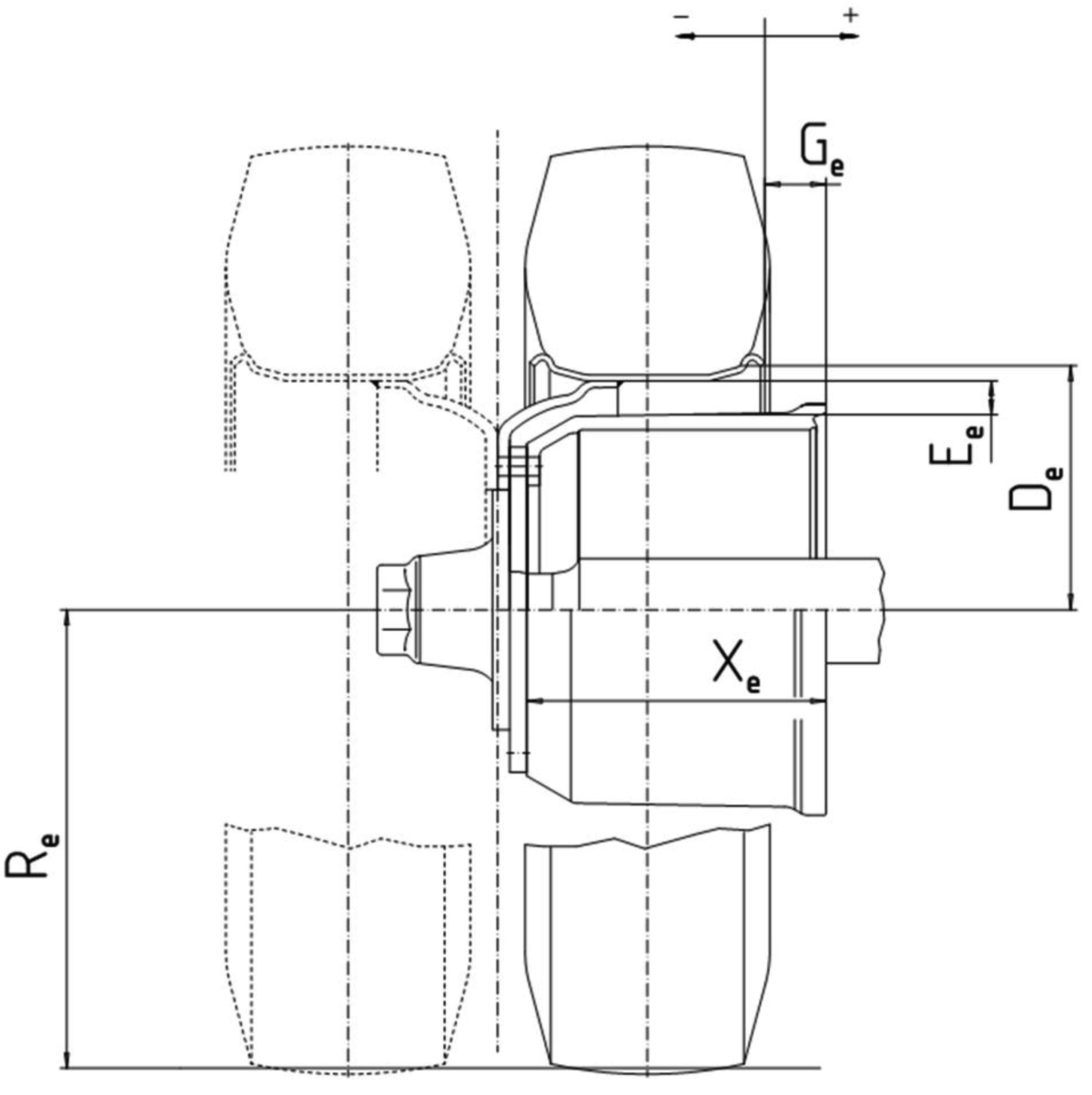
Figure 1B

Figure 2A

Figure 2B

|
xe (mm) |
ae (mm) |
he (mm) |
ce (mm) |
de (mm) |
ee (mm) |
α0e |
α1e |
be (mm) |
re (mm) |
Ae (cm2) |
S1e (mm) |
S2e (mm) |
S3e (mm) |
|
|
|
|
|
|
|
|
|
|
|
|
|
|
|
Appendix 16
Model information document relating to EU type-approval of a type of (or a type of a vehicle with regard to) a driver's exposure to noise level system
A. GENERAL INFORMATION
2. GENERAL INFORMATION CONCERNING SYSTEMS, COMPONENTS OR SEPARATE TECHNICAL UNITS
|
2.1. |
Make(s) (trade name(s) of manufacturer): … |
|
2.2. |
Type (49): …
|
|
2.3. |
Company name and address of manufacturer: …
|
|
2.4. |
For systems and separate technical units, vehicle(s) for which they are intended for (21):
|
|
2.5. |
Location and method of attachment of the type-approval mark (19): … |
48. DRIVER'S EXPOSURE TO NOISE LEVEL
|
48.1. |
T- or C-category (with rubber tracks) vehicles to be tested in accordance with Test method 1, in accordance with point 2 of Annex XIII to Commission Delegated Regulation (EU) No 1322/2014: yes/no/not applicable (4) |
|
48.2. |
T- or C-category (with rubber tracks) vehicles to be tested in accordance with Test method 2, in accordance with point 3 of Annex XIII to Commission Delegated Regulation (EU) No 1322/2014: yes/no/not applicable (4) |
|
48.3. |
C-category vehicles with steel tracks to be tested on a layer of humid sand as specified by paragraph 5.3.2 of ISO 6395:2008 (Earth-moving machinery — Determination of sound power level — Dynamic test conditions): yes/no/not applicable (4) |
|
48.4 |
Alternatively to entries 48.1 to 48.3, a complete test report issued on the basis of the OECD standard Code for the official measurement of noise at the driving position(s) on agricultural and forestry tractors, OECD Code 5, Edition 2015 of July 2014, is provided with relevant documentation included in the information document: yes/no/not applicable (4) |
Appendix 17
Model information document relating to EU type-approval of a type of (or a type of a vehicle with regard to) a seat belt anchorages system
A. GENERAL INFORMATION
2. GENERAL INFORMATION CONCERNING SYSTEMS, COMPONENTS OR SEPARATE TECHNICAL UNITS
|
2.1. |
Make(s) (trade name(s) of manufacturer): … |
|
2.2. |
Type (49): …
|
|
2.3. |
Company name and address of manufacturer: …
|
|
2.4. |
For systems and separate technical units, vehicle(s) for which they are intended for (21):
|
46. ROLL-OVER PROTECTIVE STRUCTURE (ROPS)
|
46.1. |
Equipment of ROPS: compulsory/optional/standard (4) |
49. SEATING POSITIONS (SADDLES AND SEATS)
|
49.1. |
Seating position configuration: seat/saddle (4) |
|
49.2. |
Coordinates or drawing of the Seat Reference point (S) of all seating positions: … |
|
49.3. |
Description and drawings of: 49.3.1. The seats and their anchorages: … 49.3.2. The adjustment system: … 49.3.3. The displacement and locking systems: … 49.3.4. The seat-belt anchorages (if incorporated in the seat structure): … 49.3.5. The parts of the vehicle used as anchorages: … |
53. SEAT-BELT ANCHORAGES
|
53.1. |
Requirements under standard ISO 3776-1:2006 (Tractors and machinery for agriculture — Seat belts — Part 1: Anchorage location requirements) are met with relevant documentation included in the information document: yes/no (4) |
|
53.2. |
Photographs and/or drawings of the bodywork showing the true, effective location and dimensions of the anchorages: … |
|
53.3. |
Drawings of the anchorages and the parts of the vehicle structure to which they are attached (together with a statement on the nature of the materials used): … |
|
53.4. |
Designation of the types of belts (14) authorised for attachment to the anchorages on the vehicle
|
|||||||||||||||||||||||||||||||||||||||||||||||
|
53.5. |
Special devices (example: seat-height adjustment, preloading device, etc.): … |
|
53.6. |
Description of a particular type of safety belt where an anchorage is located in the seat backrest or incorporates an energy dissipating device: … |
|
53.7. |
Alternative to entries 53.2 to 53.6.
|
Appendix 18
Model information document relating to EU type-approval of a type of (or a type of a vehicle with regard to) a protection against hazardous substances system
A. GENERAL INFORMATION
2. GENERAL INFORMATION CONCERNING SYSTEMS, COMPONENTS OR SEPARATE TECHNICAL UNITS
|
2.1. |
Make(s) (trade name(s) of manufacturer): … |
|
2.2. |
Type (49): …
|
|
2.3. |
Company name and address of manufacturer: …
|
|
2.4. |
For systems and separate technical units, vehicle(s) for which they are intended for (21):
|
3. GENERAL CONSTRUCTION CHARACTERISTICS
|
3.11. |
Vehicle of T- or C-category equipped for protection against hazardous substances: yes/no (4) |
58. PROTECTION AGAINST HAZARDOUS SUBSTANCES
|
58.1. |
Brief description (including drawings and photographs) of the air delivery and filtration system, including the devices to obtain a positive differential within the cab and the air flow of fresh filtered air: … |
|
58.2. |
Requirements under standard EN 15695-1 (Agricultural tractors and self-propelled sprayers — Protection of the operator (driver) against hazardous substances — Part 1: Cab classification, requirements and test procedures): category 1/category 2/category 3 category 4 (4) on cab classification with regard to protection against hazardous substances are met with relevant documentation included in the information document: yes/no (4) |
|
58.3. |
Requirements under standard EN 15695-2 (Agricultural tractors and self-propelled sprayers — Protection of the operator (driver) against hazardous substances — Part 2: Filters, requirements and test procedures): Dust filter/Aerosol filter/Vapour filter (4) on filters with regard to protection against hazardous substances are met with relevant documentation included in the information document: yes/no (4) |
Appendix 19
Model information document relating to EU type-approval of a roll-over protective structure (ROPS) as a STU
A. GENERAL INFORMATION
2. GENERAL INFORMATION CONCERNING SYSTEMS, COMPONENTS OR SEPARATE TECHNICAL UNITS
|
2.1. |
Make(s) (trade name(s) of manufacturer): … |
|
2.2. |
Type (49): …
|
|
2.3. |
Company name and address of manufacturer: …
|
|
2.4. |
For systems and separate technical units, vehicle(s) for which they are intended for (21):
|
46. ROLL-OVER PROTECTIVE STRUCTURE (ROPS)
|
46.1. |
Equipment of ROPS: compulsory/optional/standard (4) |
|
46.2. |
ROPS by cab/by frame/by roll bar(s) mounted at front/rear (4)
|
|
46.3. |
Photographs and detailed technical drawings showing the position of the ROPS, position of the seat index point (SIP), the details of mountings and position of the front part of the tractor capable of supporting the tractor when overturned (if necessary) etc. (in the case of front-mounted foldable ROPS, show the grasping area and a lateral and top view of the accessible zones). The main dimensions must figure on the drawings, including external dimensions of tractor with protective structure fitted and main interior dimensions: … |
|
46.4. |
Brief description of the protective structure, comprising: 46.4.1. Type of construction: … 46.4.2. Details of mountings: … 46.4.3. Details of the front part of the tractor capable of supporting the tractor when overturned (if necessary): … 46.4.4. Additional frame: … |
|
46.5. |
Dimensions (52)
|
|
46.6. |
Details of materials used in the construction of the protective structure and specifications of steels used (53)
|
|
46.7. |
Alternatively to entries 46.1 to 46.6.7, provide the following information: 46.7.1. Complete test report issued on the basis of the OECD standard Code for the official testing of protective structures on agricultural and forestry tractors (dynamic test), OECD Code 3, Edition 2015 of July 2014, is provided with relevant documentation included in the information document: yes/no/not applicable (4) 46.7.2. Complete test report issued on the basis of the OECD standard Code for the official testing of protective structures on agricultural and forestry track-laying tractors, OECD Code 8, Edition 2015 of July 2014, is provided with relevant documentation included in the information document: yes/no/not applicable (4) 46.7.3. Complete test report issued on the basis of the OECD standard Code for the official testing of protective structures on agricultural and forestry tractors (static test), OECD Code 4, Edition 2015 of July 2014, is provided with relevant documentation included in the information document: yes/no/not applicable (4) 46.7.4. Complete test report issued on the basis of the OECD standard Code for the official testing of front mounted roll-over protective structures on narrow-track wheeled agricultural and forestry tractors, OECD Code 6, Edition 2015 of July 2014, is provided with relevant documentation included in the information document: yes/no/not applicable (4) 46.7.5 Complete test report issued on the basis of the OECD standard Code for the official testing of rear mounted roll-over protective structures on narrow-track wheeled agricultural and forestry tractors, OECD Code 7, Edition 2015 of July 2014, is provided with relevant documentation included in the information document: yes/no/not applicable (4) |
Appendix 20
Model information document relating to EU type-approval of a falling objects protective structure (FOPS) as a STU
A. GENERAL INFORMATION
2. GENERAL INFORMATION CONCERNING SYSTEMS, COMPONENTS OR SEPARATE TECHNICAL UNITS
|
2.1. |
Make(s) (trade name(s) of manufacturer): … |
|
2.2. |
Type (49): …
|
|
2.3. |
Company name and address of manufacturer: …
|
|
2.4. |
For systems and separate technical units, vehicle(s) for which they are intended for (21):
|
47. FALLING OBJECT PROTECTIVE STRUCTURES (FOPS)
47.1. Vehicles of categories T and C equipped for forestry applications
|
47.1.1. |
Requirements under ISO 8083:2006 (Machinery for forestry — Falling-object protective structures (FOPS) — Laboratory tests and performance requirements) level I/level II (4) are met with relevant documentation included in the information document: yes/no (4) |
47.2. All other vehicles of categories T and C fitted with FOPS
|
47.2.1. |
Photographs and detailed technical drawings showing the position of the FOPS, position of the seat index point (SIP), etc. The main dimensions must figure on the drawings, including external dimensions of tractor with protective structure fitted and main interior dimensions: … |
|
47.2.2. |
Brief description of the protective structure, comprising: 47.2.2.1. Type of construction: … 47.2.2.2. Details of mountings: … |
|
47.2.3. |
Dimensions (52)
|
|
47.2.4. |
Details of materials used in the construction of the protective structure and specifications of steels used (53)
|
|
47.2.5. |
Details of tractor manufacturer's reinforcements on original parts: … |
|
47.2.6. |
Alternatively to entries 47.2.1 to 47.2.5, a complete test report issued on the basis of the OECD standard Code for the official testing of falling object protective structures on agricultural and forestry tractors, OECD Code 10, Edition 2015 of July 2014 is provided with relevant documentation included in the information document: yes/no (4) |
Appendix 21
Model information document relating to EU type-approval of a driver's seat as a component/STU
A. GENERAL INFORMATION
2. GENERAL INFORMATION CONCERNING SYSTEMS, COMPONENTS OR SEPARATE TECHNICAL UNITS
|
2.1. |
Make(s) (trade name(s) of manufacturer): … |
|
2.2. |
Type (49): …
|
|
2.3. |
Company name and address of manufacturer: …
|
|
2.4. |
For systems and separate technical units, vehicle(s) for which they are intended for (21):
|
49. SEATING POSITIONS (SADDLES AND SEATS)
|
49.1. |
Seating position configuration: seat/saddle (4) |
|
49.2. |
Coordinates or drawing of the Seat Reference point (S) of the driver's seat: … |
|
49.3. |
Description and drawings of: 49.3.1. The seat and its anchorages: … 49.3.2. The adjustment system: … 49.3.3. The displacement and locking systems: … 49.3.4. The seat-belt anchorages (if incorporated in the seat structure): … 49.3.5. The parts of the vehicle used as anchorages: … |
|
49.4. |
Driver's seat
|
Appendix 22
Model information document relating to EU type-approval of a safety belt as a component/STU
A. GENERAL INFORMATION
2. GENERAL INFORMATION CONCERNING SYSTEMS, COMPONENTS OR SEPARATE TECHNICAL UNITS
|
2.1. |
Make(s) (trade name(s) of manufacturer): … |
|
2.2. |
Type (49): …
|
|
2.3. |
Company name and address of manufacturer: …
|
|
2.4. |
For systems and separate technical units, vehicle(s) for which they are intended for (21):
|
54. SAFETY BELTS
|
54.1. |
Requirements under standard ISO 3776-3:2009 (Tractors and machinery for agriculture — Seat belts — Part 3: Requirements for assemblies) are met with relevant documentation included in the information document: yes/no (4) |
|
54.2. |
Test report granted a on the basis of UNECE Regulation No 16 (OJ L 233, 9.9.2011, p. 1) with relevant documentation included in the information document: yes/no (4) |
|
54.3. |
Number and position of safety belts and seats on which they can be used, please fill out table below:
Safety belt configuration and associated information
|
||||||||||||||||||||||||||||||||||||||||||||||||||||||
|
54.4. |
Brief description of electrical/electronic components: … |
Appendix 23
Model information document relating to EU type-approval of a protection against penetrating objects (OPS) as a STU
A. GENERAL INFORMATION
2. GENERAL INFORMATION CONCERNING SYSTEMS, COMPONENTS OR SEPARATE TECHNICAL UNITS
|
2.1. |
Make(s) (trade name(s) of manufacturer): … |
|
2.2. |
Type (49): …
|
|
2.3. |
Company name and address of manufacturer: …
|
|
2.4. |
For systems and separate technical units, vehicle(s) for which they are intended for (21):
|
55. PROTECTION AGAINST PENETRATING OBJECTS (OPS)
55.1. Vehicles of categories T and C equipped for forestry applications
|
55.1.1. |
Requirements under ISO 8084:2003 (Machinery for forestry — Operator protective structures — Laboratory tests and performance requirements) are met with relevant documentation included in the information document: yes/no (4) |
55.2. All other T- and C-category vehicles fitted with OPS
|
55.2.1. |
Requirements under Annex 14 to UNECE Regulation 43 (OJ L 230, 31.8.2010, p. 119) on safety glazing are met with the relevant documentation included in the information document: yes/no (4) |
Appendix 24
Manufacturer’s declaration on anti-tampering of powertrain and speed-limitation device
Manufacturer’s declaration on anti-tampering of powertrain and speed-limitation device
A duly-completed version of this statement shall be included in the information folder.
The undersigned: [… (full name and position)]
2.3. Company name and address of manufacturer: …
2.3.2. Name and address of the manufacturer’s authorised representative (if any) ( 5 ): …
Hereby declares that:
2.1. Make(s) (trade name(s) of manufacturer: …
2.4.1. Type ( 6 ): …
2.4.2. Variant(s) (6) : …
2.4.3. Version(s) (6) : …
2.4.4 Commercial name(s) (if available): …
2.4.5. Category, subcategory and speed index of vehicle ( 7 ): …
Will not market interchangeable components which could involve an increase in the propulsion performance of the vehicle variant
Place: … Date: …
Signature: … Name and position in the company: …
Explanatory notes relating to Appendix 24
(Footnote markers, footnotes and explanatory notes not to be stated on the Manufacturer’s declaration)
Explanatory notes relating to the information document
(Footnote markers, footnotes and explanatory notes not to be stated on the data entries)
(1) For tyres type-approved in accordance with the requirements laid down in section 2 of Annex XXX to Commission Delegated Regulation (EU) 2015/208 or approved in accordance with UNECE Regulation No 106, indicate the ‘Rolling radius, expressed by the speed radius index’; for tyres approved under UNECE Regulation No 54 or UNECE Regulation No 75 indicate the ‘Nominal Rolling Circumference’.
(2) Classified according to Article 4 of Regulation (EU) No 167/2013, the coding shall be indicated, e.g. ‘T4.3a’ for a low-clearance tractor with a maximum design speed below or equal to 40 km/h.
(3) Delete the entry if not applicable.
(4) Delete where not applicable (no deletion required when more than one value is applicable).
(5) Indicate the configuration by following codes:
|
— |
R : right side of the vehicle |
|
— |
L : left side of the vehicle |
|
— |
F : front side of the vehicle |
|
— |
RE : rear side of the vehicle |
Example for a vehicle with 2 left-side doors and 1 right-side door:
2 L, 1R
(6) This value shall be calculated (p = 3,1416) and rounded off to the nearest cm3. For rotary piston engines, double the nominal engine swept volume.
(7) Specify the tolerance.
(8) Indicate the position by the following codes:
|
— |
Rx : row number |
|
— |
R : right side of the vehicle |
|
— |
C : centre of the vehicle |
|
— |
L : left side of the vehicle |
Example for a vehicle with a second row with 1 passenger seat on the left side of the vehicle:
r2: 1L
(9) Indicate fuel type by the following codes:
P: petrol
B5: diesel
E5: petrol E5
M: mixture (for two stroke engines)
O: other.
(10) For EU whole-vehicle type-approval, describe the manifold installed on the vehicle; for EU type-approval of an engine/engine family as a component/STU, describe one of the possible manifolds that can be installed on the engine.
(11) Excluding SLI batteries that supply electric energy for starting, lighting and ignition.
(12) This figure shall be rounded off to the nearest tenth of a millimetre.
(13) The specified particulars are to be given for any proposed variants.
(14) ‘A’: for a three-point belt;
‘B’: for a lap belt;
‘S’: for special types of belt (in this case provide specific information on the nature of these types under observation in entry 53.4.1.);
‘Ar’, ‘Br’ or‘Sr’: for a belt incorporating an inertia reel retractor;
‘Are’, ‘Bre’ and ‘Sre’: for a belt equipped with an inertia reel retractor and an energy-absorption device on at least one anchorage.
(15) Only applicable to T- and C-category vehicles authorized to tow R- or S-category vehicles if fitted with a hydraulic energy storage device.
(16) Indicate the maximum towable mass on the lower link arms of the rear three-point lifting mechanism or the rear three-point lifting mechanism itself, as declared by the manufacturer.
(17) Indicate the alphanumeric code Type-Variant-Version or ‘TVV’ allocated to each type, variant and version as set out in point 2.3 of Part B of Annex I to this Regulation. For the identification of variant and versions it may be employed the matrix set out in point 2.2 of Part B of Annex I to this Regulation.
(18) In case of multi-stage approval, supply this information for each stage.
(19) Provide this information for each component and separate technical unit installed in the vehicle or system.
(21) Provide this information for each vehicle type/system.
(22) Powered and braked track rollers:
F : front
R : rear
F & R : front and rear
C : continuous track
Examples:
|
— |
rear powered track rollers : R |
|
— |
Continuous track braked : C |
(23) Axles with twinned wheels/steered/powered/braked:
F : front
R : rear
A : articulated vehicles
F & R : front and rear
F & A : front and articulated
A & R : articulated and rear
F & A & R : front, articulated and rear
Examples:
|
— |
front twinned wheels : F |
|
— |
front and articulated steering : F & A |
|
— |
rear powered axles : R |
|
— |
front and rear braked axles : F & R |
(24) Indicate the type of gear shift system(s) by the following codes:
A: automatic
M1: manual
M2: manual automated
C: continuous variable transmission (CVT)
W: wheel-hub engine
O: other (indicate…)
(26) Indicate the layout of the cylinders by following codes:
LI: in line
V: in V
O: opposed-cylinder engine
S: single-cylinder engine
R: rotatory piston engine.
(29) For compression ignition engines only.
(30) Serving as a reference point for the various delegated acts. Including the roll-over protection structure, excluding optional accessories, but with coolant, lubricants, fuel, tools and driver The mass of the driver shall be assumed to be 75 kg.
(31) Standard ISO 612/-6.1:1978 (Road vehicles — Dimensions of motor vehicles and towed vehicles — Terms and definitions).
(32) Standard ISO 612/-6.2:1978 (Road vehicles — Dimensions of motor vehicles and towed vehicles — Terms and definitions).
(33) Standard ISO 612/-6.3:1978 (Road vehicles — Dimensions of motor vehicles and towed vehicles — Terms and definitions). For vehicles with height adjustable suspension, state the normal running position.
(34) Standard ISO 612/-6.6:1978 (Road vehicles — Dimensions of motor vehicles and towed vehicles — Terms and definitions).
(35) Standard ISO 612/-6.7:1978 (Road vehicles — Dimensions of motor vehicles and towed vehicles — Terms and definitions).
(36) Standard ISO 612/-6.8:1978 (Road vehicles — Dimensions of motor vehicles and towed vehicles — Terms and definitions).
(37) for tractors and drawbar R- or S-category vehicles, wheelbase is the distance from first to last axle; for rigid drawbar and centre-axle R- or S-category vehicles, is the distance from centre of front coupling point to last axle.
(38) Standard ISO 4004:1983 (Agricultural tractors and machinery — Track widths).
(39) If a part has been type-approved that part need not be described if reference is made to such approval. Likewise the description is not needed for all components whose structural characteristics are clearly illustrated by the diagrams or sketches attached to the document. State the numbers of the corresponding annexes for each heading where photographs or drawings must be attached.
(40) In the case of applications involving more than one parent engine, a separate form should be submitted for each one.
(41) A measured speed exceeding the value for the maximum design speed by 3 km/h shall be acceptable. An additional 5 % tolerance shall be permitted in order to take into account variations due to tyre size.
(42) Standard ISO 789-3:1993 (Agricultural tractors — Test procedures — Part 3: Turning and clearance diameters).
(44) Values in respect of the mechanical strength of the coupling device.
(45) Not applicable to types of vehicles, systems, components and separate technical units falling under the requirements of Article 37 or Article 53(13) of Regulation (EU) No 167/2013.
(46) Also applicable to R- or S-category vehicles with a rear coupling device.
(47) For R- and S-category vehicles indicate the height without optional side/rear panels.
(48) For R- and S-category vehicles indicate the overhang of the front coupling point.
(49) For engines indicate the information relative to the engine type or the engine family type, as applicable without the type-approval extension number.
(52) When the tractor is fitted with different optional seats or has a reversible driver’s position (reversible seat and steering wheel), the dimensions in relation to the seat index points (SIP 1, SIP 2, etc.) shall be measured for each case.
(53) Steel specifications shall be in accordance with ISO 630:1995 (Structural steels — Plates, wide flats, bars, sections and profiles), Amd 1: 2003.
(54) Indicate in case that the maximum design speed in the rearward direction of travel is higher than in the forward direction of travel.
(55) Provide the requested information for: Service braking system; Parking braking system; for vehicles of categories T and C, Secondary braking system; for any additional braking device(s) (and especially retarders) and; for anti-lock braking systems.
(56) To be completed in conjunction with the specifications given in sections 9.1 and 9.2 of Annex I to Commission Delegated Regulation (EU) 2015/96
(57) OECD standard code for the official testing of agricultural and forestry tractor performance, OECD Code 2, Edition 2015 of July 2014.
(59) As defined in point 1.1 of Annex VIII to Commission Delegated Regulation (EU) 2015/208.
(60) Relevant vehicle electrical/electronic systems or ESAs are those which may emit significant broadband or narrowband radiation and/or those which are involved in the driver's direct control (see point 3.4.2.3 of Part 2 of Annex XV to Commission Delegated Regulation (EU) 2015/208) of the vehicle
(61) Applicable only for small volume manufacturers as regards section 6 of Annex V to Commission Delegated Regulation (EU) No 1322/2014.
(62) Alternatively, provide a dimensioned drawing showing the position of the coupling point.
(63) Machinery, as defined in Article 2(a) of Directive 2006/42/EC of the European Parliament and of the Council.
ANNEX II
Template for the manufacturer's certificate on access to vehicle on-board diagnostics (OBD) and to vehicle repair and maintenance information
|
1. |
The vehicle manufacturer shall provide, in accordance with Article 53(8) of Regulation (EU) No 167/2013, the certificates providing proof of compliance to the type-approval authority on access to vehicle OBD and vehicle repair and maintenance information which shall take the form set out in point 2.
|
|
2. |
Manufacturer's certificate on access to vehicle OBD and vehicle repair and maintenance information and its addenda.
|
Explanatory notes relating to Annex II
(Footnote markers, footnotes and explanatory notes not to be stated on the manufacturer's certificates)
(1) Delete if not applicable.
(2) Indicate the alphanumeric code Type-Variant-Version or ‘TVV’ allocated to each type, variant and version as set out in point 2.3 of Part B of Annex I to this Regulation. For the identification of variant and versions it may be employed the matrix set out in point 2.2 of Part B of Annex I to this Regulation.
(3) Classified according to Article 4 of Regulation (EU) No 167/2013, the coding shall be indicated, e.g. ‘T4.3a’ for a low-clearance tractor with a maximum design speed below or equal to 40 km/h.
(4) For engines indicate the information relative to the engine type or the engine family type, as applicable without the type-approval extension number.
(5) In case of multi-stage type-approval indicate the website address of the manufacturer(s) responsible for the previous stage(s).
ANNEX III
Templates for the certificate of conformity
1. Objectives
The certificate of conformity enables the competent authorities of the Member States to register vehicles without requiring the applicant to supply additional technical documentation. For these purposes, the certificate of conformity shall include:
(a) the vehicle identification number;
(b) the exact technical characteristics of the vehicle (e.g. it is not permitted to mention any range of value in the various entries).
2. General requirements
2.1. The vehicle manufacturer shall provide, in accordance with Article 33(1) of Regulation (EU) No 167/2013, a certificate of conformity for each vehicle in the series of the type which has been approved, which template is set out in the Appendix 1.
2.2. The certificate of conformity shall consist of two sections:
(a) section 1 contains a statement of compliance by the manufacturer. There are different templates for section 1 according to the vehicles covered, as specified in point 3;
(b) section 2 is a technical description of the main characteristics of the vehicle. There are different templates for section 2 according to the vehicles' category covered, as specified in point 4. Those entries which are not applicable to the certified vehicle can be supressed.
2.3. The certificate of conformity shall be no bigger than A4 paper format (210 × 297 mm).
2.4 All information on the certificate of conformity shall be provided in ISO 8859 series (Information technology — 8-bit single-byte coded graphic character sets) characters (for certificates of conformity issued in Bulgarian language in Cyril characters, for certificates of conformity issued in Greek language in Greek characters) and Arabic numerals.
2.5. Without prejudice to the provisions in point 1(b), the values and units indicated in section 2 of the certificate of conformity shall be those given in the information document of the vehicle type. The tolerances allowed are those laid down in the relevant requirements of the delegated acts adopted pursuant to Regulation (EU) No 167/2013. Maximum and minimum values are accepted for vehicles' dimensions (Length, Width and Height) to take into account their different configurations of wheels and tyres.
3. Models of section 1 of the certificate of conformity
3.1. Model A of section 1 of the certificate of conformity (complete vehicles) shall cover vehicles which can be used on the road without further approval.
3.2. Model B of section 1 of the certificate of conformity (completed vehicles) shall cover vehicles which can also be used on the road without requiring any further approval, and which have previously undergone an additional approval stage.
This is the normal result of the multi-stage approval process (e.g. a T1-category tractor built by a second-stage manufacturer on a chassis built by another vehicle manufacturer).
The additional features added during the multi-stage process shall be described briefly and the certificates of conformity obtained at the previous stages shall be annexed.
3.3. Model C of section 1 of the certificate of conformity (incomplete vehicles) shall cover vehicles which need a further stage for their approval and cannot be permanently registered or used on the road (e.g. a chassis of a T2-category tractor).
4. Models of section 2 of the certificate of conformity
There are two models of section 2 of the certificate of conformity:
(a) Model 1 of section 2 of the certificate of conformity for wheeled tractors (T category vehicles) and track-laying tractors (C category vehicles);
(b) Model 2 of section 2 of the certificate of conformity for trailers (R-category vehicles) and interchangeable towed equipment (S-category vehicles).
5. Paper and features to prevent forgery
5.1. In accordance with Article 33(2) of Regulation (EU) No 167/2013, the certificate of conformity shall be made in such a way as to prevent any forgery. For this purpose, the paper used for the certificate of conformity shall be protected by a watermark in the form of the registered mark of the manufacturer or brand name and by coloured graphics.
5.2. As an alternative to the requirements set out in point 5.1, the paper of the certificate of conformity may be not protected by a watermark in the form of the registered mark of the manufacturer or brand name. In this case, the coloured graphics shall be supplemented with at least one additional security printing feature (e.g. ultraviolet fluorescent ink, inks with viewing angle-dependent colour, inks with temperature-dependent colour, micro printing, guilloche printing, iridescent printing, laser engraving, custom holograms, variable laser images, optical variable images, physically embossed or engraved manufacturer's logo, etc.)
5.3. Manufacturers may provide the certificate of conformity with security printing features additional to those set out in points 5.1 and 5.2.
6. Special provisions
6.1. The certificate of conformity of tractors (T- and C-category vehicles) type-approved with machinery mounted on them and of R- and S-category vehicles shall have as attachment the EC declaration of conformity in compliance with the national provisions implementing Directive 2006/42/EC.
Appendix 1
Models for the certificate of conformity
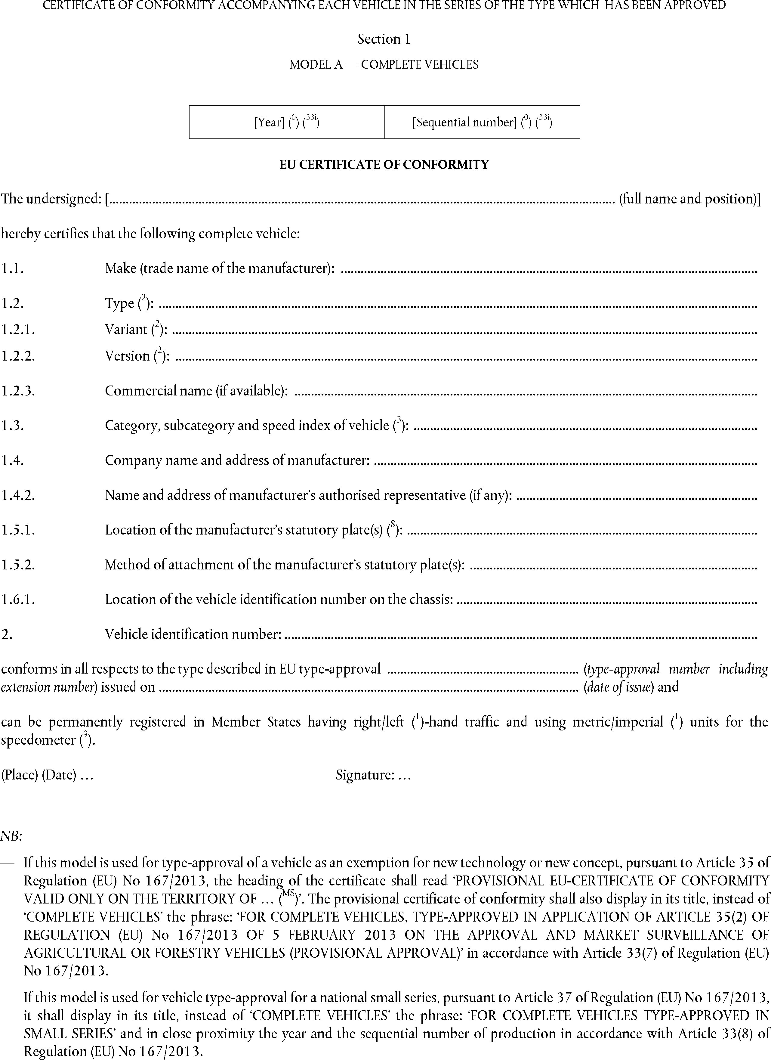


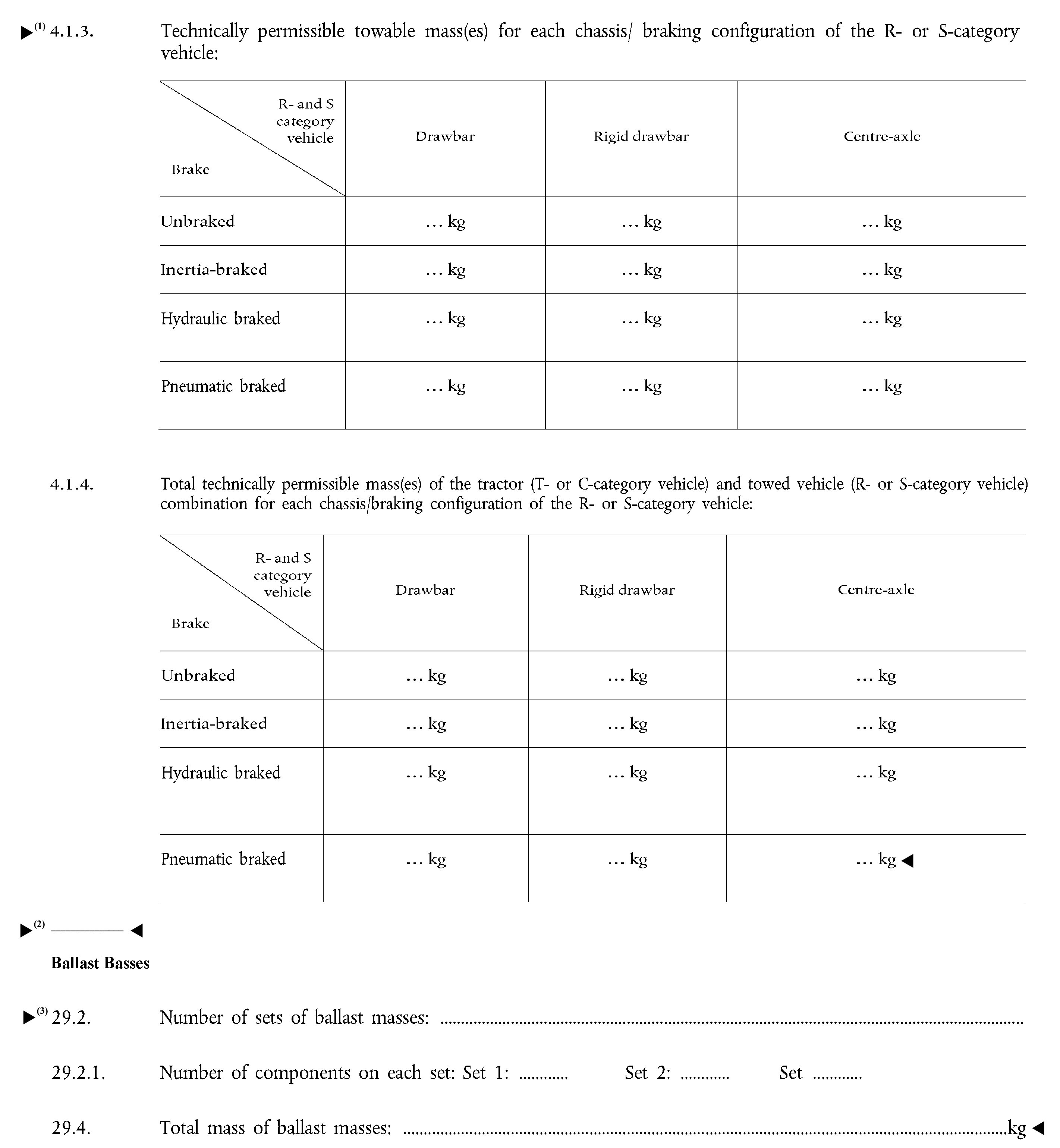


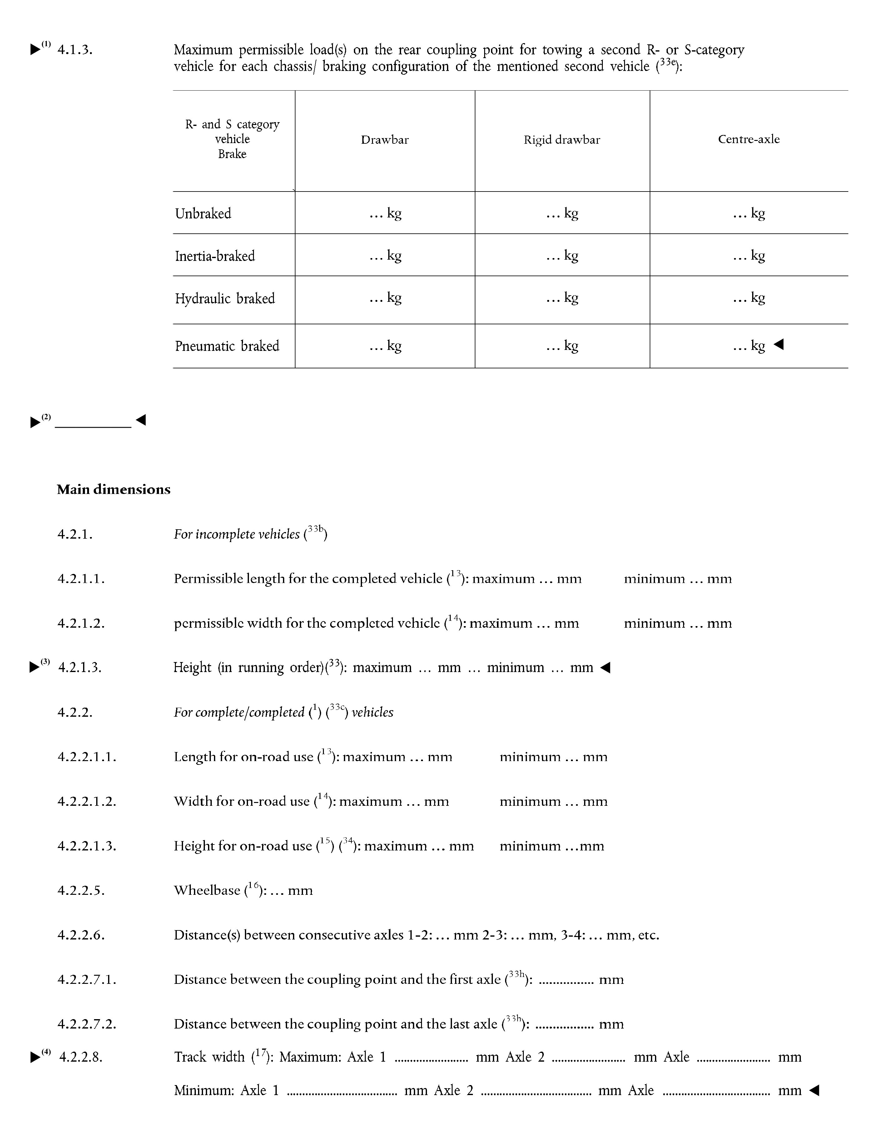

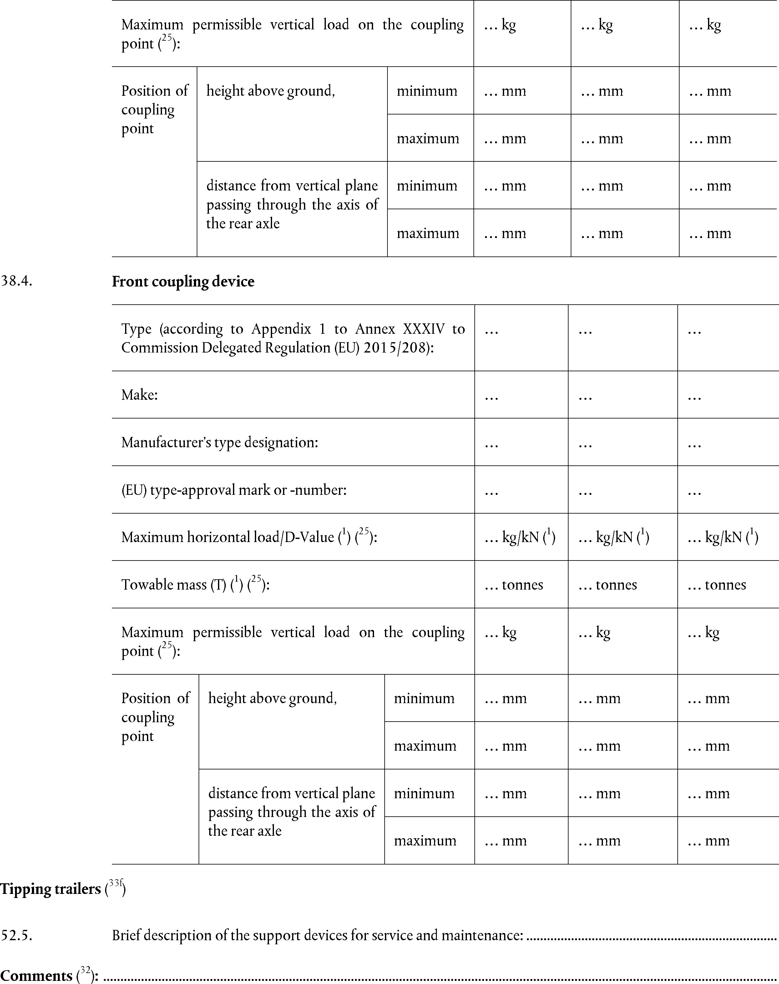


ANNEX IV
Models for the statutory plate and EU type-approval mark
1. General requirements for vehicle marking
|
1.1. |
All vehicles shall be provided with the plate described in this section in accordance with Article 34(1) of Regulation (EU) No 167/2013. The plate shall be attached by the vehicle manufacturer. |
|
1.2. |
Characters
|
|
1.3. |
Minimum height of letters and figures.
|
2. Statutory plate
|
2.1.1. |
The information on the plate shall be clearly legible, indelible and shall contain the following information in the order given below and in accordance with one of the two alternative models set out in Appendix 1: 2.1.1.1. Name of the manufacturer, and trade name (only if different than the name of the manufacturer); 2.1.1.2. Vehicle category including the subcategory and the speed index (1); 2.1.1.3. EU type-approval number in accordance with point 3 of Annex VI; 2.1.1.4. Vehicle identification number (VIN); consisting of a structured combination of characters in accordance with the requirements set out in section 3 of this Annex; 2.1.1.5. Technically permissible maximum laden mass of the vehicle, in the following format: ‘kg’; 2.1.1.6. Technically permissible maximum mass per axle; this information must be listed in order from front to rear, in the following format: ‘A-1: … kg’‘A-2: … kg’‘A-…: … kg’; 2.1.1.7. For C-category vehicles, in addition, technically permissible maximum mass per set of track trains, and, in the same line, average contact pressure on the ground; this information must be combined with that provided for point 2.1.1.6 and listed in order from front to rear, in the following format: ‘S-1: … kg P: … kPa’‘S-2: … kg P: … kPa’‘S-…: … kg P: … kPa’. Each entry separated by one or more spaces. 2.1.1.8. Technically permissible towable mass(es) for each chassis/ braking configuration of the towed R- or S-category vehicle in accordance with entry 4.1.3 of the information document data entries laid down in Part B of Annex I to this Regulation (2), in the following format: ‘B-1’ unbraked, ‘B-2’ inertia braked, ‘B-3’ hydraulic braked, ‘B-4’ pneumatic braked, ‘T-1’ drawbar, ‘T-2’ rigid drawbar, ‘T-3’ centre-axle; 2.1.1.9. For rigid drawbar or centre-axle R- and S-category vehicles, the vertical load on the coupling point (S). The coupling point shall be deemed the first axle and be numbered ‘0’, in the following format: ‘A-0: … kg’; |
|
2.1.2. |
The manufacturer may give additional information below or to the side of the prescribed inscriptions, outside a clearly marked area which shall enclose only the information prescribed in points 2.1.1.1 to 2.1.1.9 (see examples in Appendix 1) |
3. Requirements for the VIN
The VIN shall comply with the requirements of the standard ISO 10261:2002 (Earth-Moving Machinery — Product Identification Numbering System) or the standard ISO 3779: 2009 (Road vehicles — Vehicle identification number (VIN) — Content and structure).
4. Marking requirements for a multi-stage approval
4.1. Base vehicle identification number
The VIN of the base vehicle conforming to the requirements set out in section 3 shall be retained during all subsequent stages of type-approval to ensure the ‘traceability’ of the process.
4.2. Additional statutory plate.
|
4.2.1. |
At the second and subsequent stages, in addition to the statutory plate referred to in section 2, each manufacturer shall affix to the vehicle an additional plate, based on the model set out in Appendix 1. This plate shall be firmly attached, in a conspicuous and readily accessible position to a part which is not subject to replacement during normal use, regular maintenance or repair. It shall show clearly and indelibly the following information in the order listed: 4.2.1.1. Name of the manufacturer, 4.2.1.2. The EU type-approval number in accordance with point 3 of Annex VI, 4.2.1.3. Vehicle category including the subcategory and the speed index (1) and stage of approval (in case of base vehicles, this first-stage identification shall be omitted; in the case of subsequent stages, the information shall indicate the stage: e.g. ‘STAGE 3’ for the third stage), each entry separated by one or more spaces, 4.2.1.4. VIN, 4.2.1.5. Technically permissible maximum laden mass of the vehicle, in the following format: ‘kg’; 4.2.1.6. Technically permissible maximum mass per axle; this information must be listed in order from front to rear, in the following format: ‘A-1: … kg’‘A-2: … kg’‘A-…: … kg’; 4.2.1.7. For C-category vehicles, in addition, technically permissible maximum mass per set of track trains, and, in the same line, average contact pressure on the ground; this information must be combined with that provided for point 4.1.1.6 and listed in order from front to rear, in the following format: ‘S-1: … kg P: … kPa’‘S-2: … kg P: … kPa’‘S-…: … kg P: … kPa’. Each entry separated by one or more spaces. 4.2.1.8. Technically permissible towable mass(es) for each chassis/ braking configuration of the towed R- or S-category vehicle in accordance with entry 4.1.3 of the information document data entries laid down in Part B of Annex I to this Regulation (2), in the following format: ‘B-1’ unbraked, ‘B-2’ inertia braked, ‘B-3’ hydraulic braked, ‘B-4’ pneumatic braked, ‘T-1’ drawbar, ‘T-2’ rigid drawbar, ‘T-3’ centre-axle; 4.2.1.9. For rigid drawbar or centre-axle R- and S-category vehicles, the vertical load on the coupling point (S). The coupling point shall be deemed the first axle and be numbered ‘0’, in the following format: ‘A-0: … kg’; |
5. Marking requirements for components or separate technical units
|
5.1. |
Each separate technical unit or component, whether or not part of a system, which has been EU type-approved and manufactured in conformity with the approved type shall be marked with an EU type-approval mark in accordance with Article 34(2) of Regulation (EU) No 167/2013.
|
|
5.2. |
The EU type-approval mark for a separate technical unit or component shall consist of: 5.2.1. A rectangle surrounding the lower-case letter ‘e’ followed by the distinguishing number, as set out in point 2.1 of Annex VI to the Member State which has granted the EU type-approval for the separate technical unit or component. 5.2.2. In the vicinity of the rectangle, the ‘Sequential number for type-approval certificates’ contained in section 4 of the EU type-approval number as set out in point 2.4 of Annex VI. In addition, it shall be indicated the alphanumerical character as set out in Table 6-1 of Annex VI to clearly identify the type of component or separate technical unit. 5.2.3. Examples of the EU type-approval mark for a separate technical unit or component are shown in Appendix 2. The dimensions of ‘a’ shall be:
|
|
5.3. |
In addition, the make, trade name or trade mark shall be marked in the vicinity of the EU type-approval mark. |
Appendix 1
Examples of the statutory plate
1. MODEL A for a T1b-category vehicle
|
SOFIA TRAKTOR WERKE. T1b e6*167/2013*01223 5DRH123UPAX000001 5 590 kg A-1: 2 390 kg A-2: 3 200 kg |
|||||
|
|
|
T-1 |
T-2 |
T-3 |
|
|
B-1 |
3 000 kg |
4 000 kg |
2 000 kg |
||
|
B-2 |
3 000 kg |
4 000 kg |
2 000 kg |
||
|
B-3 |
6 000 kg |
8 000 kg |
4 000 kg |
||
|
B-4 |
12 000 kg |
15 000 kg |
9 000 kg |
||
|
|
|||||
2. MODEL B alternative to MODEL A for a T1b-category vehicle
|
|
|
||||
|
SOFIA TRAKTOR WERKE. T1b e6*167/2013*01223 5DRH123UPAX000001 5 590 kg A-1: 2 390 kg A-2: 3 200 kg |
|
T-1 |
T-2 |
T-3 |
|
|
B-1 |
3 000 kg |
4 000 kg |
2 000 kg |
|
|
|
B-2 |
3 000 kg |
4 000 kg |
2 000 kg |
|
|
|
B-3 |
6 000 kg |
8 000 kg |
4 000 kg |
|
|
|
B-4 |
12 000 kg |
15 000 kg |
9 000 kg |
|
|
|
|
|
||||
3. MODEL C for stage 1 of a C2a-category vehicle
|
JEAN NICOLE TRACTORS Ltd. C2a STAGE 1 e3*167/2013*14863 ZFS159000AZ000055 820 kg A-1: 366 kg S-2: 454 kg P: 255 kPa |
|||||
|
|
|
T-1 |
T-2 |
T-3 |
|
|
B-1 |
1 000 kg |
2 000 kg |
1 000 kg |
||
|
B-2 |
1 000 kg |
2 000 kg |
1 000 kg |
||
|
B-3 |
2 000 kg |
3 000 kg |
2 000 kg |
||
|
B-4 |
4 000 kg |
5 000 kg |
4 000 kg |
||
|
|
|||||
4. MODEL D alternative to MODEL C for stage 1 of a C2a-category vehicle
|
|
|
||||
|
JEAN NICOLE TRACTORS Ltd. C2a STAGE 1 e3*167/2013*14863 ZFS159000AZ000055 820 kg A-1: 366 kg S-2: 454 kg P: 255 kPa |
|
T-1 |
T-2 |
T-3 |
|
|
B-1 |
1 000 kg |
2 000 kg |
1 000 kg |
|
|
|
B-2 |
1 000 kg |
2 000 kg |
1 000 kg |
|
|
|
B-3 |
2 000 kg |
3 000 kg |
2 000 kg |
|
|
|
B-4 |
4 000 kg |
5 000 kg |
4 000 kg |
|
|
|
|
|
||||
5. MODEL E for a rigid drawbar R2a-category vehicle
|
REMORQUES HENSCHLER SA. R2a e12*167/2013*00053 YA9EBS37009000005 2 050 kg A-0: 1 100 kg A-1: 850 kg A-2: 1 200 kg |
|||||
|
|
|
T-1 |
T-2 |
T-3 |
|
|
B-1 |
1 000 kg |
1 000 kg |
1 000 kg |
||
|
B-2 |
1 000 kg |
1 000 kg |
1 000 kg |
||
|
B-3 |
2 000 kg |
2 000 kg |
2 000 kg |
||
|
B-4 |
2 000 kg |
2 000 kg |
2 000 kg |
||
|
|
|||||
6. MODEL F alternative to MODEL E for a rigid drawbar R2a-category vehicle
|
|
|
||||
|
REMORQUES HENSCHLER SA. R2a e12*167/2013*00053 YA9EBS37009000005 2 050 kg A-0: 1 100 kg A-1: 850 kg A-2: 1 200 kg |
|
T-1 |
T-2 |
T-3 |
|
|
B-1 |
1 000 kg |
1 000 kg |
1 000 kg |
|
|
|
B-2 |
1 000 kg |
1 000 kg |
1 000 kg |
|
|
|
B-3 |
2 000 kg |
2 000 kg |
2 000 kg |
|
|
|
B-4 |
2 000 kg |
2 000 kg |
2 000 kg |
|
|
|
|
|
||||
Appendix 2
Examples of an EU type-approval mark for a separate technical unit or component
Figure 1
Example of EU type-approval mark of a roll-over protective structure (ROPS) (dynamic testing)

Explanatory note relating to figure 1:
The above EU type-approval mark was issued by Portugal under number 00024 for a roll-over protective structure (ROPS) (dynamic testing).
Explanatory notes relating to Annex IV
(Footnote markers, footnotes and explanatory notes not to be stated on the manufacturer's certificates):
(1) Classified according to Article 4 of Regulation (EU) No 167/2013, the coding shall be indicated, e.g. ‘T4.3a’ for a low-clearance tractor with a maximum design speed below or equal to 40 km/h.
(2) For R- and S-category vehicles fitted with a rear mechanical coupling, indicate the maximum permissible load(s) on the rear coupling point for towing a second R- or S-category vehicle for each chassis/braking configuration of the mentioned second vehicle.
ANNEX V
Templates for the EU type-approval certificate
LIST OF APPENDICES
|
Appendix Number |
Appendix title |
|
1 |
Model of the EU whole-vehicle type-approval certificate for a complete vehicle type |
|
2 |
Model of the EU whole-vehicle type-approval certificate for an incomplete type, a vehicle type with complete and incomplete variants, a vehicle type with completed and incomplete variants or a completed vehicle type |
|
3 |
Model of the addendum to the EU type-approval certificate |
|
4 |
Model of the EU type-approval certificate for a vehicle system |
|
5 |
Model of the EU type-approval certificate for a separate technical unit or component |
|
6 |
Model of the addendum to the EU type-approval certificate for a separate technical unit or component |
1. General requirements
|
1.1. |
Model A of the EU whole-vehicle type-approval certificate for a complete vehicle type is set out in Appendix 1. |
|
1.2. |
Model B of the EU whole-vehicle type-approval certificate for an incomplete vehicle type, a vehicle type with complete and incomplete variants, a vehicle type with completed and incomplete variants or a completed vehicle type is set out in Appendix 2. |
|
1.3. |
The list of applicable requirements or acts with which the type of vehicle complies and which are appended to the EU whole-vehicle type-approval certificate when the manufacturer chooses the single-step type-approval procedure according to Article 25(6) of Regulation (EU) No 167/2013 is set out in Appendix 3. |
|
1.4. |
Model C of the EU type-approval certificate for a vehicle system is set out in Appendix 4. |
|
1.5. |
Model D of the EU type-approval certificate for a separate technical unit or component is set out in Appendix 5.
|
|
1.6. |
The type-approval certificate shall be no bigger than A4 paper format (210 × 297 mm). |
Appendix 1
Model of the EU whole-vehicle type-approval certificate for a complete vehicle type
EU TYPE-APPROVAL CERTIFICATE
MODEL A
(to be used for type-approval of a complete vehicle)
EU WHOLE-VEHICLE TYPE-APPROVAL CERTIFICATE
Communication concerning:
|
— EU whole-vehicle type-approval (1) — extension of EU whole-vehicle type-approval (1) — refusal of EU whole-vehicle type-approval (1) — withdrawal of EU whole-vehicle type-approval (1) |
|
with regard to Regulation (EU) No 167/2013, as last amended by (Commission Delegated) (1) Regulation (EU) (No) (1) …/… (1) (5) (of the European Parliament and of the Council) (1)
EU type-approval number: …
Reason for extension/refusal/withdrawal (1): …
SECTION I
|
1.1. |
Make (trade name of manufacturer): … |
|
1.2. |
Type (2): …
|
|
1.3. |
Category, subcategory and speed index of vehicle (3): … |
|
1.4. |
Company name and address of manufacturer of the complete vehicle: …
|
SECTION II
|
1. |
Technical service responsible for carrying out the tests: … |
|
2. |
Date of test report: … |
|
3. |
Number of test report: … |
SECTION III
The undersigned hereby certifies the accuracy of the manufacturer's description in the attached information document of the vehicle type described above, for which one or more representative samples, selected by the EU type-approval authority, have been submitted as prototypes of the vehicle type and that the attached test results apply to the vehicle type.
|
1. |
The complete vehicle type meets/does not meet (1) all relevant requirements as listed in Annex I to Regulation (EU) No 167/2013.
|
|
2. |
The approval is granted/extended/refused/withdrawn (1)
|
Place: …
Date: …
Name and signature (or visual representation of an ‘advanced electronic signature’ according to Directive 1999/93/EC of the European Parliament and of the Council, including data for verification):
Attachments:
Information package
Test results
Name(s) and specimen(s) of the signature(s) of the person(s) authorised to sign certificates of conformity and a statement of their position in the company
A completed specimen of the certificate of conformity
NB:
— If this model is used for type-approval of a vehicle as an exemption for new technology or new concept, pursuant to Article 35 of Regulation (EU) No 167/2013, the heading of the certificate shall read ‘EU WHOLE-VEHICLE PROVISIONAL TYPE-APPROVAL CERTIFICATE VALID ONLY ON THE TERRITORY OF … (4)’. The provisional type-approval certificate shall also specify the restrictions that have been imposed as to its validity in accordance with Article 25(4) of Regulation (EU) No 167/2013.
— If this model is used for vehicle type-approval for a national small series, pursuant to Article 37 of Regulation (EU) No 167/2013, it shall not bear the heading ‘EU VEHICLE TYPE-APPROVAL CERTIFICATE’. The text shall specify the nature of the waivers, the reasons for them and the alternative requirements pursuant to Article 37(2) of Regulation (EU) No 167/2013.
Explanatory notes relating to Appendix 1
(Footnote markers, footnotes and explanatory notes not to be stated on the EU whole-vehicle type-approval certificate):
(1) Delete where not applicable.
(2) Indicate the alphanumeric code Type-Variant-Version or ‘TVV’ allocated to each type, variant and version as set out in point 2.3 of Part B of Annex I to this Regulation. For the identification of variant and versions it may be employed the matrix set out in point 2.2 of Part B of Annex I to this Regulation.
(3) Classified according to Article 4 of Regulation (EU) No 167/2013, the coding shall be indicated, e.g. ‘T4.3a’ for a low-clearance tractor with a maximum design speed below or equal to 40 km/h.
(4) Indicate the Member State.
(5) Indicate only the latest amendment in case of an amendment of one or more Articles of Regulation (EU) No 167/2013, according to the amendment applied for the EU type-approval.
(6) Applicable only for type-approval of a vehicle as an exemption for new technology or new concept, pursuant to Article 35 of Regulation (EU) No 167/2013.
(7) Applicable only for vehicle type-approval for a national small series, pursuant to Article 37 of Regulation (EU) No 167/2013.
Appendix 2
Model of the EU whole-vehicle type-approval certificate for an incomplete type, a vehicle type with complete and incomplete variants, a vehicle type with completed and incomplete variants or a completed vehicle type
EU TYPE-APPROVAL CERTIFICATE
MODEL B
(to be used for type-approval of a completed or incomplete vehicle or a vehicle type with complete and incomplete variants or with completed and incomplete variants)
EU WHOLE-VEHICLE TYPE-APPROVAL CERTIFICATE
Communication concerning:
|
— EU whole-vehicle type-approval (1) — extension of EU whole-vehicle type-approval (1) — refusal of EU whole-vehicle type-approval (1) — withdrawal of EU whole-vehicle type-approval (1) |
|
with regard to Regulation (EU) No 167/2013, as last amended by (Commission Delegated) (1) Regulation (EU) (No) (1) …/… (1) (8) (of the European Parliament and of the Council) (1)
EU type-approval number (1): …
Reason for extension/refusal/withdrawal (1): …
SECTION I
|
1.1. |
Make (trade name of manufacturer): … |
|
1.2. |
Type (2): …
|
|
1.3. |
Category, subcategory and speed index of vehicle (3): … |
|
1.4. |
Company name and address of the manufacturer of the base vehicle (1) (4): … Company name and address of the manufacturer of the complete variant (1) (4): … Company name and address of the manufacturer of the completed vehicle/variant (1) (4): … Company name and address of the manufacturer of the latest built stage of the incomplete vehicle (1) (4): … Company name(s) and address(es) of the manufacturer(s) of all previous stage(s) (1) (4): …
|
SECTION II
|
1. |
Technical service responsible for carrying out the tests: … |
|
2. |
Date of test report: … |
|
3. |
Number of test report: … |
SECTION III
The undersigned hereby certifies the accuracy of the manufacturer's description in the attached information document of the vehicle type described above, for which one or more representative samples, selected by the EU type-approval authority, have been submitted as prototypes of the vehicle type and that the attached test results apply to the vehicle type.
1. For complete variants
|
1.1. |
The complete variants of the vehicle type meet/do not meet (1) all relevant requirements as listed in Annex I to Regulation (EU) No 167/2013. |
2. For completed vehicles/variants
|
2.1. |
The completed vehicle type/completed variant of the vehicle type meets/does not meet (1) all relevant requirements as listed in Annex I to Regulation (EU) No 167/2013 (4):
|
3. For incomplete vehicles/variants
|
3.1. |
The incomplete vehicle type/incomplete variants of the vehicle type meets/does not meet (1) the technical requirements of the regulatory acts listed in the table in point 2 of section 2 (4). |
4. The approval is granted/extended/refused/withdrawn (1)
|
4.1. |
The approval is granted in accordance with Article 35 of Regulation (EU) No 167/2013 and its validity is thus limited to dd/mm/yyyy (6). |
|
5. |
Restrictions of validity (1) (6): … |
|
6. |
Waivers applied (1) (7): …
|
Place: …
Date: …
Name and signature (or visual representation of an ‘advanced electronic signature’ according to Directive 1999/93/EC of the European Parliament and of the Council, including data for verification): …
Attachments:
Information package
Test results
Name(s) and specimen(s) of the signature(s) of the person(s) authorised to sign certificates of conformity and a statement of their position in the company
A completed specimen of the certificate of conformity
NB:
— If this model is used for type-approval of a vehicle as an exemption for new technology or new concept, pursuant to Article 35 of Regulation (EU) No 167/2013, the heading of the certificate shall read ‘EU WHOLE-VEHICLE PROVISIONAL TYPE-APPROVAL CERTIFICATE VALID ONLY ON THE TERRITORY OF … (5)’. The provisional type-approval certificate shall also specify the restrictions that have been imposed as to its validity in accordance with Article 25(4) of Regulation (EU) No 167/2013.
— If this model is used for vehicle type-approval for a national small series, pursuant to Article 37 of Regulation (EU) No 167/2013, it shall not bear the heading ‘EU VEHICLE TYPE-APPROVAL CERTIFICATE’. The text shall specify the nature of the waivers, the reasons for them and the alternative requirements pursuant to Article 37(2) of Regulation (EU) No 167/2013.
EU WHOLE-VEHICLE TYPE-APPROVAL CERTIFICATE
SECTION 2
This EU type-approval concerns incomplete and completed vehicles, variants or versions.
1. Previous stage(s) approval(s) for the vehicles.
|
Stage |
EU type-approval number |
Dated |
Applicable to (as appropriate) |
Variants and versions which are complete or completed (as appropriate) (9) |
|
1 (base vehicle) |
|
|
|
|
|
2 |
|
|
|
|
2. List of requirements applicable to the approved incomplete vehicle type, variant, taking account of the scope and latest amendment to each of the regulatory acts listed below (10).
|
Item |
Subject |
Regulatory act reference |
As amended by and/or stage of implementation |
Applicable to variants |
|
|
|
|
|
|
Explanatory notes relating to Appendix 2
(Footnote markers, footnotes and explanatory notes not to be stated on the EU whole-vehicle type-approval certificate):
(1) Delete where not applicable.
(2) Indicate the alphanumeric code Type-Variant-Version or ‘TVV’ allocated to each type, variant and version as set out in point 2.3 of Part B of Annex I to this Regulation. For the identification of variant and versions it may be employed the matrix set out in point 2.2 of Part B of Annex I to this Regulation.
(3) Classified according to Article 4 of Regulation (EU) No 167/2013, the coding shall be indicated, e.g. ‘T4.3a’ for a low-clearance tractor with a maximum design speed below or equal to 40 km/h.
(4) See section 2.
(5) Indicate the Member State.
(6) Applicable only for type-approval of a vehicle as an exemption for new technology or new concept, pursuant to Article 35 of Regulation (EU) No 167/2013
(7) Applicable only for vehicle type-approval for a national small series, pursuant to Article 37 of Regulation (EU) No 167/2013
(8) Indicate only the latest amendment in case of an amendment of one or more Articles of Regulation (EU) No 167/2013, according to the amendment applied for the EU type-approval.
(9) In the case where the approval includes one or more incomplete variants or versions (as appropriate), list those variants or versions (as appropriate) which are complete or completed.
(10) List only subjects referred to in Annex I to Regulation (EU) No 167/2013 whose approvals have been granted in accordance with Directive 97/68/EC or the UNECE regulations referred to in Article 49 of Regulation (EU) No 167/2013 (UNECE approvals), or are based on complete test reports issued on the basis of the OECD standard Codes as an alternative to the test reports drawn up under Regulation (EU) No 167/2013 and the delegated and implementing acts adopted pursuant to that Regulation.
Appendix 3
Model of the addendum to the EU type-approval certificate
Addendum to the EU type-approval certificate
List of regulatory acts with which the type of vehicle complies
To be filled in only in the case of type-approval in accordance with Article 25(6) of Regulation (EU) No 167/2013
|
Item |
Subject |
Regulatory act reference |
As amended by and/or stage of implementation |
Applicable to version |
|
VEHICLE FUNCTIONAL SAFETY REQUIREMENTS |
||||
|
1 |
Vehicle structure integrity |
Commission Delegated Regulation (EU) 2015/208 Annex II |
|
|
|
2 |
Maximum design speed, speed governors and speed limitation devices |
Commission Delegated Regulation (EU) 2015/208 Annex III |
|
|
|
3 |
Steering for fast tractors |
Commission Delegated Regulation (EU) 2015/208 Annex IV |
|
|
|
4 |
Steering |
Commission Delegated Regulation (EU) 2015/208 Annex V |
|
|
|
5 |
Speedometers |
Commission Delegated Regulation (EU) 2015/208 Annex VI |
|
|
|
6 |
Field of vision and windscreen wipers |
Commission Delegated Regulation (EU) 2015/208 Annex VII |
|
|
|
7 |
Glazing |
Commission Delegated Regulation (EU) 2015/208 Annex VIII |
|
|
|
8 |
Rear-view mirrors |
Commission Delegated Regulation (EU) 2015/208 Annex IX |
|
|
|
9 |
Driver information systems |
Commission Delegated Regulation (EU) 2015/208 Annex X |
|
|
|
10 |
Lighting, light signalling devices and their light sources |
Commission Delegated Regulation (EU) 2015/208 Annex XI |
|
|
|
11 |
Lighting installation |
Commission Delegated Regulation (EU) 2015/208 Annex XII |
|
|
|
12 |
Vehicle occupant protection, including interior fittings, head restraints, seat belts, vehicle doors |
Commission Delegated Regulation (EU) 2015/208 Annex XIII |
|
|
|
13 |
Vehicle exterior and accessories |
Commission Delegated Regulation (EU) 2015/208 Annex XIV |
|
|
|
14 |
Electro-magnetic compatibility |
Commission Delegated Regulation (EU) 2015/208 Annex XV |
|
|
|
15 |
Audible warning devices |
Commission Delegated Regulation (EU) 2015/208 Annex XVI |
|
|
|
16 |
Heating systems |
Commission Delegated Regulation (EU) 2015/208 Annex XVII |
|
|
|
17 |
Devices to prevent unauthorised use |
Commission Delegated Regulation (EU) 2015/208 Annex XVIII |
|
|
|
18 |
Registration plates |
Commission Delegated Regulation (EU) 2015/208 Annex XIX |
|
|
|
19 |
Statutory plates and markings |
Commission Delegated Regulation (EU) 2015/208 Annex XX |
|
|
|
20 |
Dimensions and trailer masses |
Commission Delegated Regulation (EU) 2015/208 Annex XXI |
|
|
|
21 |
Maximum laden mass |
Commission Delegated Regulation (EU) 2015/208 Annex XXII |
|
|
|
22 |
Ballast masses |
Commission Delegated Regulation (EU) 2015/208 Annex XXIII |
|
|
|
23 |
Safety of electrical systems |
Commission Delegated Regulation (EU) 2015/208 Annex XXIV |
|
|
|
24 |
Fuel tanks |
Commission Delegated Regulation (EU) 2015/208 Annex XXV |
|
|
|
25 |
Rear protective structures |
Commission Delegated Regulation (EU) 2015/208 Annex XXVI |
|
|
|
26 |
Lateral protection |
Commission Delegated Regulation (EU) 2015/208 Annex XXVII |
|
|
|
27 |
Load platforms |
Commission Delegated Regulation (EU) 2015/208 Annex XXVIII |
|
|
|
28 |
Towing devices |
Commission Delegated Regulation (EU) 2015/208 Annex XXIX |
|
|
|
29 |
Tyres |
Commission Delegated Regulation (EU) 2015/208 Annex XXX |
|
|
|
30 |
Spray-suppression systems |
Commission Delegated Regulation (EU) 2015/208 Annex XXXI |
|
|
|
31 |
Reverse gear |
Commission Delegated Regulation (EU) 2015/208 Annex XXXII |
|
|
|
32 |
Tracks |
Commission Delegated Regulation (EU) 2015/208 Annex XXXIII |
|
|
|
33 |
Mechanical couplings |
Commission Delegated Regulation (EU) 2015/208 Annex XXXIV |
|
|
|
VEHICLE BRAKING REQUIREMENTS |
||||
|
34 |
Construction and fitting of braking devices and trailer braking couplings |
Commission Delegated Regulation (EU) 2015/68 Annex I |
|
|
|
35 |
Testing and performance of braking systems and trailer braking couplings and of vehicles fitted with them |
Commission Delegated Regulation (EU) 2015/68 Annex II |
|
|
|
36 |
Measurement of the response time |
Commission Delegated Regulation (EU) 2015/68 Annex III |
|
|
|
37 |
Energy sources and energy storage devices of braking systems and trailer braking couplings and to vehicles fitted with them |
Commission Delegated Regulation (EU) 2015/68 Annex IV |
|
|
|
38 |
Spring brakes and vehicles fitted with them |
Commission Delegated Regulation (EU) 2015/68 Annex V |
|
|
|
39 |
Parking braking systems equipped with a mechanical brake-cylinder locking device |
Commission Delegated Regulation (EU) 2015/68 Annex VI |
|
|
|
40 |
Alternative test requirements for vehicles for which Type-I, Type-II or Type-III tests are not mandatory |
Commission Delegated Regulation (EU) 2015/68 Annex VII |
|
|
|
41 |
Testing of inertia braking systems, braking devices and trailer braking couplings and of vehicles fitted with them as regards braking |
Commission Delegated Regulation (EU) 2015/68 Annex VIII |
|
|
|
42 |
Vehicles with hydrostatic drive and their braking devices and braking systems |
Commission Delegated Regulation (EU) 2015/68 Annex IX |
|
|
|
43 |
Safety aspects of complex electronic vehicle control systems |
Commission Delegated Regulation (EU) 2015/68 Annex X |
|
|
|
44 |
Test procedures applying to anti-lock braking systems and to vehicles fitted with them |
Commission Delegated Regulation (EU) 2015/68 Annex XI |
|
|
|
45 |
EBS of vehicles with compressed-air braking systems or of vehicles with data communication via pin 6 and 7 of ISO 7638 connector and to vehicles fitted with such EBS |
Commission Delegated Regulation (EU) 2015/68 Annex XII |
|
|
|
46 |
Hydraulic connections of the single-line type and to vehicles fitted with them |
Commission Delegated Regulation (EU) 2015/68 Annex XIII |
|
|
|
VEHICLE CONSTRUCTION AND GENERAL TYPE-APPROVAL REQUIREMENTS |
||||
|
47 |
Arrangements with regard to type-approval procedures, including the requirements relating to virtual testing |
Commission Delegated Regulation (EU) No 1322/2014 Annex III |
|
|
|
48 |
Arrangements with regard to conformity of production |
Commission Delegated Regulation (EU) No 1322/2014 Annex IV |
|
|
|
49 |
Access to repair and maintenance information |
Commission Delegated Regulation (EU) No 1322/2014 Annex V |
|
|
|
50 |
Roll-over protection structures (dynamic testing) |
Commission Delegated Regulation (EU) No 1322/2014 Annex VI |
|
|
|
51 |
Roll-over protection structures (track-laying tractors) |
Commission Delegated Regulation (EU) No 1322/2014 Annex VII |
|
|
|
52 |
Roll-over protection structures (static testing) |
Commission Delegated Regulation (EU) No 1322/2014 Annex VIII |
|
|
|
53 |
Roll-over protection structures (front mounted roll-over protective structures on narrow-track tractors) |
Commission Delegated Regulation (EU) No 1322/2014 Annex IX |
|
|
|
54 |
Roll-over protection structures (rear mounted roll-over protective structures on narrow-track tractors) |
Commission Delegated Regulation (EU) No 1322/2014 Annex X |
|
|
|
55 |
Falling objects protection structures |
Commission Delegated Regulation (EU) No 1322/2014 Annex XI |
|
|
|
56 |
Passenger seats |
Commission Delegated Regulation (EU) No 1322/2014 Annex XII |
|
|
|
57 |
Driver's exposure to noise level |
Commission Delegated Regulation (EU) No 1322/2014 Annex XIII |
|
|
|
58 |
Driving seat |
Commission Delegated Regulation (EU) No 1322/2014 Annex XIV |
|
|
|
59 |
Operating space and to access to the driving position |
Commission Delegated Regulation (EU) No 1322/2014 Annex XV |
|
|
|
60 |
Power take-offs |
Commission Delegated Regulation (EU) No 1322/2014 Annex XVI |
|
|
|
61 |
Protection of drive components |
Commission Delegated Regulation (EU) No 1322/2014 Annex XVII |
|
|
|
62 |
Seat-belt anchorages |
Commission Delegated Regulation (EU) No 1322/2014 Annex XVIII |
|
|
|
63 |
Safety belts |
Commission Delegated Regulation (EU) No 1322/2014 Annex XIX |
|
|
|
64 |
Protection against penetrating objects |
Commission Delegated Regulation (EU) No 1322/2014 Annex XX |
|
|
|
65 |
Exhaust system |
Commission Delegated Regulation (EU) No 1322/2014 Annex XXI |
|
|
|
66 |
Operator's manual |
Commission Delegated Regulation (EU) No 1322/2014 Annex XXII |
|
|
|
67 |
Control devices, including safety and reliability of control systems and emergency and automatic stop devices |
Commission Delegated Regulation (EU) No 1322/2014 Annex XXIII |
|
|
|
68 |
Protection against other mechanical hazards |
Commission Delegated Regulation (EU) No 1322/2014 Annex XXIV |
|
|
|
69 |
Guards and protective devices |
Commission Delegated Regulation (EU) No 1322/2014 Annex XXV |
|
|
|
70 |
Information warnings and markings |
Commission Delegated Regulation (EU) No 1322/2014 Annex XXVI |
|
|
|
71 |
Materials and products |
Commission Delegated Regulation (EU) No 1322/2014 Annex XXVII |
|
|
|
72 |
Batteries |
Commission Delegated Regulation (EU) No 1322/2014 Annex XXVIII |
|
|
|
73 |
Protection against hazardous substances |
Commission Delegated Regulation (EU) No 1322/2014 Annex XXIX |
|
|
|
74 |
Performance standards and assessment of technical services |
Commission Delegated Regulation (EU) No 1322/2014 Annex XXX |
|
|
|
ENVIRONMENTAL AND PROPULSION UNIT PERFORMANCE REQUIREMENTS |
||||
|
75 |
EU type-approval of a type of engine or engine family for an agricultural and forestry vehicle type as a separate technical unit regarding the pollutants emitted |
Commission Delegated Regulation (EU) 2015/96 Annex I |
|
|
|
76 |
EU type-approval of an agricultural and forestry vehicle type equipped with an engine type or engine family regarding the pollutants emitted |
Commission Delegated Regulation (EU) 2015/96 Annex II |
|
|
|
77 |
External sound emission |
Commission Delegated Regulation (EU) 2015/96 Annex III |
|
|
Appendix 4
Model of the EU type-approval certificate for a vehicle system
EU TYPE-APPROVAL CERTIFICATE
MODEL C
(to be used for type-approval of a vehicle system)
EU TYPE-APPROVAL CERTIFICATE
Communication concerning:
|
— EU type-approval (1) — extension of EU type-approval (1) — refusal of EU type-approval (1) — withdrawal of EU type-approval (1) |
|
with regard to Annex(es) (7) … to Commission Delegated Regulation(s) (EU) (No) (1) …/…, (and Annex(es) … (7) to Commission Delegated Regulation (EU) (No) (1) …/…) (1) as last amended by (Commission Delegated) (1) Regulation (EU) (No) (1) …/… (1) (6) (of the European Parliament and of the Council) (1)
EU type-approval number (1): …
Reason for extension/refusal/withdrawal (1): …
SECTION I
|
2.1. |
Make(s) (trade name(s) of manufacturer): … |
|
2.2. |
Type: …
|
|
2.3. |
Company name and address of the manufacturer: …
|
|
2.4. |
Vehicle(s) for which is intended for (8):
|
SECTION II
|
1. |
Technical service responsible for carrying out the tests: … |
|
2. |
Date of test report: … |
|
3. |
Number of test report: … |
SECTION III
The undersigned hereby certifies the accuracy of the manufacturer's description in the attached information document of the type of system/type of a vehicle with regard to a system (1) (0) described above, for which one or more representative samples, selected by the EU type-approval authority, have been submitted as prototypes of the type of (0) … and that the attached test results apply to the type of (0) …
|
1. |
The type of system/type of a vehicle with regard to a system (1) (0) and the component(s) and/or separate technical unit(s) installed on the vehicle(s) (9) meets/does not meet (1) the technical requirements of the relevant regulatory acts. |
|
2. |
The approval is granted/extended/refused/withdrawn (1)
|
|
3. |
Restrictions of validity (1) (6): … |
Place: …
Date: …
Name and signature (or visual representation of an ‘advanced electronic signature’ according to Directive 99/93/EC, including data for verification): …
Attachments:
Information package
Test report
NB:
If this model is used for type-approval of a system as an exemption for new technology or new concept, pursuant to Article 35 of Regulation (EU) No 167/2013, the heading of the certificate shall read ‘EU PROVISIONAL TYPE-APPROVAL CERTIFICATE VALID ONLY ON THE TERRITORY OF … (4)’, The provisional type-approval certificate shall also specify the restrictions that have been imposed as to its validity in accordance with Article 25(4) of Regulation (EU) No 167/2013.
EU TYPE-APPROVAL CERTIFICATE
Section 2
This EU type-approval concerns a type of system/type of a vehicle with regard to a system (1) (0).
Component(s) and/or separate technical unit(s) to be installed on the vehicle type (8) to comply with the system type-approval:
|
Component/Separate technical unit (10) |
alphanumerical character (10) |
Type-approval number |
|
|
|
|
Explanatory notes relating to Appendix 4
(Footnote markers, footnotes and explanatory notes not to be stated on the EU type-approval certificate for a vehicle system):
(0) Indicate the system, component or separate technical unit according to first column of Table 6-1 of Annex VI to this Regulation (e.g. installation of an engine/engine family)
(1) Delete where not applicable.
(2) Indicate the alphanumeric code Type-Variant-Version or ‘TVV’ allocated to each type, variant and version as set out in point 2.3 of Part B of Annex I to this Regulation. For the identification of variant and versions it may be employed the matrix set out in point 2.2 of Part B of Annex I to this Regulation.
(3) Classified according to Article 4 of Regulation (EU) No 167/2013, the coding shall be indicated, e.g. ‘T4.3a’ for a low-clearance tractor with a maximum design speed below or equal to 40 km/h.
(4) Indicate the Member State.
(5) Applicable only for type-approval of a system as an exemption for new technology or new concept, pursuant to Article 35 of Regulation (EU) No 167/2013.
(6) Indicate the latest amendment of the Commission Delegated Regulation according to the amendment applied for the EU type-approval.
(7) The Roman numeral of the relevant Annex to the Commission Delegated Regulation or multiple Roman numerals of the relevant Annexes to the same Commission Delegated Regulation.
(8) Provide this information for each vehicle type.
(9) See section 2.
(10) In accordance with Table 6-1 of Annex VI to this Regulation.
Appendix 5
Model of the EU type-approval certificate for a separate technical unit or component
EU TYPE-APPROVAL CERTIFICATE
MODEL D
(to be used for component/separate technical unit type-approval)
EU TYPE-APPROVAL CERTIFICATE
Communication concerning:
|
— EU type-approval (1) — extension of EU type-approval (1) — refusal of EU type-approval (1) — withdrawal of EU type-approval (1) |
|
with regard to Annex(es) … (5) to Commission Delegated Regulation (EU) (No) (1) …/… (and Annex(es) … (5) to Commission Delegated Regulation (EU) (No) (1) …/…) (1), as last amended by (Commission Delegated) (1) Regulation (EU) …/… (1) (6) (of the European Parliament and of the Council) (1)
EU type-approval number (1): …
Reason for extension/refusal/withdrawal (1): …
SECTION I
|
2.1. |
Make(s) (trade name(s) of manufacturer): … |
|
2.2. |
Type: …
|
|
2.3. |
Company name and address of the manufacturer: …
|
|
2.4. |
In the case of separate technical unit, vehicle(s) for which is intended for (6):
|
|
2.6. |
Location and method of attachment of the type-approval mark: … |
SECTION II
|
1. |
Technical service responsible for carrying out the tests: … |
|
2. |
Date of test report: … |
|
3. |
Number of test report: … |
SECTION III
The undersigned hereby certifies the accuracy of the manufacturer's description in the attached information document of the type of component/separate technical unit (1) (0) described above, for which one or more representative samples, selected by the EU type-approval authority, have been submitted as prototypes of the type of (0) … and that the attached test results apply to the type of (0) …
|
1. |
The type of component/separate technical unit (1) (0) meets/does not meet (1) the technical requirements of the relevant regulatory acts. |
|
2. |
The approval is granted/extended/refused/withdrawn (1)
|
|
3. |
Restrictions of validity (1) (4): … |
Place: …
Date: …
Name and signature (or visual representation of an ‘advanced electronic signature’ according to Directive 1999/93/EC of the European Parliament and of the Council, including data for verification): …
Attachments:
Information package
Test report
NB:
If this model is used for type-approval of a component or separate technical unit as an exemption for new technology or new concept, pursuant to Article 35 of Regulation (EU) No 167/2013, the heading of the certificate shall read ‘EU PROVISIONAL TYPE-APPROVAL CERTIFICATE VALID ONLY ON THE TERRITORY OF … (3)’, The provisional type-approval certificate shall also specify the restrictions that have been imposed as to its validity in accordance with Article 25(4) of Regulation (EU) No 167/2013.
Explanatory notes relating to Appendix 5
(Footnote markers, footnotes and explanatory notes not to be stated on the EU type-approval certificate for a separate technical unit or component):
(0) Indicate the component/separate technical unit according to first column of Table 6-1 of Annex VI to this Regulation (e.g. roll-over protective structure (ROPS) (dynamic testing)).
(1) Delete where not applicable.
(2) Indicate the alphanumeric code Type-Variant-Version or ‘TVV’ allocated to each type, variant and version as set out in point 2.3 of Part B of Annex I to this Regulation. For the identification of variant and versions it may be employed the matrix set out in point 2.3 of Part B of Annex I to this Regulation.
(3) Indicate the Member State.
(4) Applicable only for type-approval of a component or separate technical unit as an exemption for new technology or new concept, pursuant to Article 35 of Regulation (EU) No 167/2013
(5) The Roman numeral of the relevant Annex to the Commission Delegated Regulation or multiple Roman numerals of the relevant Annexes to the same Commission Delegated Regulation.
(6) Provide this information for each vehicle type.
Appendix 6
Model of the addendum to the EU type-approval certificate for a separate technical unit or component
Addendum to the EU type-approval certificate
ADDENDUM TO THE EU TYPE-APPROVAL CERTIFICATE WITH TYPE-APPROVAL NUMBER …
|
1. |
Restriction of use of the ( 8 ) ( 9 ) … ( 10 ): … … … … |
|
2. |
Special conditions for the mounting of the (8) (9) … (10) : … … … … |
|
3. |
Remarks (8) : … … … … |
Explanatory notes relating to Appendix 6
(Footnote markers, footnotes and explanatory notes not to be stated on the addendum to the EU type-approval certificate):
ANNEX VI
Numbering system of EU type-approval certificates
|
1. |
EU type-approval certificates shall be numbered in accordance with the method set out in this Annex. |
|
2. |
The EU type-approval number shall consist of a total of four sections for whole-vehicle type-approvals and five sections for type-approval of systems, components, and separate technical units as detailed below. In all cases, the sections shall be separated by an asterisk (‘*’).
|
|
3. |
On the vehicle's statutory plate(s) only, section 5 shall be omitted. |
|
4. |
Lay-out of the type-approval numbers (with fictive sequential numbers and fictive amending Commission Delegated Regulation number (‘RRR/2016’) for explanation purposes) Example of a component unit type-approval of a tyre, which has not yet been extended, issued by France: — e2*2015/208*2015/208M*00003*00 —
Example of a vehicle system type-approval of an installation of an engine/engine family, amended by another Commission Delegated Regulation RRR/2016 which has been extended twice, issued by Bulgaria: — e34*2015/96*RRR/2016A*00403*02 —
Example of a national small series whole vehicle type-approval, which has been extended once, issued by Austria and granted in accordance with Article 42 of Regulation (EU) No 167/2013: — e12*NKS167/2013*00001*01 —
Example of a whole vehicle type-approval number, which has been extended five times, issued by the Netherlands: — e4*167/2013*10690*05 —
Table 6-1 Codification for the numbering system of EU type-approval certificates of systems, components and separate technical units
LIST I — Environmental and propulsion unit performance requirements
LIST II — Vehicle functional safety requirements
LIST III — Vehicle braking requirements
LIST IV — Vehicle construction and general type-approval requirements
|
ANNEX VII
Template for the test results sheet
1. General requirements
|
1.1. |
The type-approval authority shall provide and attach to the EU type-approval certificate, in accordance with Article 25(3) of Regulation (EU) No 167/2013, the test results sheet which shall take the form set out in Appendix 1 to this Annex. |
|
1.2. |
In each case, the information must make clear to which variant and version it is applicable. One version may not have more than one result. However, a combination of several results per version indicating the worst case is permissible. In the latter case, a note shall state that for items marked (*) only worst case results are given. |
Appendix 1
Model of the test results sheet
EU TEST RESULTS SHEET
MODEL
Format: A4 (210 × 297 mm)
TEST RESULTS
(to be completed by the EU type-approval authority and attached to the EU type-approval certificate)
1. Results of the sound level test (external):
Measured according to Annex III to Commission Delegated Regulation (EU) 2015/96, as last amended by Commission Delegated Regulation (EU) …/… (1) (3)
|
Variant/version: |
… |
… |
… |
|
Moving: |
… dB(A) |
… dB(A) |
… dB(A) |
|
Stationary: |
… dB(A) |
… dB(A) |
… dB(A) |
|
Engine speed: |
… min–1 |
… min–1 |
… min–1 |
2. Results of the exhaust emission tests
Measured according to:
— Annex I to Commission Delegated Regulation (EU) 2015/96, as last amended by Commission Delegated Regulation (EU) …/… (1) (3): yes/no (1);
— Annex XII to Directive 97/68/EC of the European Parliament and of the Council, as last amended by (Commission) (1) Directive No …/…/EU (1) (4): yes/no (1);
— Regulation (EC) No 595/2009 of the European Parliament and of the Council, as last amended by (Commission Delegated) (1) Regulation (EU) (No) (1) …/… (1) (5) (of the European Parliament and of the Council) (1): yes/no (1); or
— Annex 4B to UNECE Regulation No 96.04 series of amendments (OJ L 88, 22.3.2014, p. 1): yes/no (1).
2.1. NRSC/ESC/WHSC (1) final test results (inclusive of Deterioration Factor):
|
Variant/Version |
… |
… |
… |
|
Stage |
… |
… |
… |
|
CO |
… g/kWh |
… g/kWh |
… g/kWh |
|
HC |
… g/kWh |
… g/kWh |
… g/kWh |
|
NOx (6) |
… g/kWh |
… g/kWh |
… g/kWh |
|
HC+NOx |
… g/kWh |
… g/kWh |
… g/kWh |
|
PM |
… g/kWh |
… g/kWh |
… g/kWh |
|
CO2 |
… g/kWh |
… g/kWh |
… g/kWh |
2.2. NRTC/ETC/WHTC (1) final test results (inclusive of Deterioration Factor and weighted average of hot start and cold start transient cycles) (2):
|
Variant/Version |
… |
… |
… |
|
Stage |
… |
… |
… |
|
CO |
… g/kWh |
… g/kWh |
… g/kWh |
|
HC |
… g/kWh |
… g/kWh |
… g/kWh |
|
NOx |
… g/kWh |
… g/kWh |
… g/kWh |
|
NMHC |
… g/kWh |
… g/kWh |
… g/kWh |
|
CH4 |
… g/kWh |
… g/kWh |
… g/kWh |
|
PM |
… g/kWh |
… g/kWh |
… g/kWh |
|
NRTC hot cycle CO2 |
… g/kWh |
… g/kWh |
… g/kWh |
|
NRTC hot cycle work |
… kWh |
… kWh |
… kWh |
|
Cycle work for hot start w/o regeneration |
… kWh |
… kWh |
… kWh |
3. Driver-perceived sound level
Measured according to Annex XIII to Commission Delegated Regulation (EU) No 1322/2014, as last amended by Commission Delegated Regulation (EU) …/… (1) (3)
|
Variant/version: |
… |
… |
… |
|
Driver's exposure to noise level |
… dB(A) |
… dB(A) |
… dB(A) |
|
Test method used: |
|
|
|
|
Test method 1 in accordance with section 2 of Annex XIII to Commission Delegated Regulation (EU) No 1322/2014 (1) |
— |
— |
— |
|
Test method 2 in accordance with: section 3 of Annex XIII to Commission Delegated Regulation (EU) No 1322/2014 (1) |
|
|
|
4. Braking performance
Measured according to Annex II to Commission Delegated Regulation (EU) 2015/68, as last amended by Commission Delegated Regulation (EU) …/… (1) (3)
Table I
|
|
Axles of the vehicle |
Reference axles |
||||
|
Static mass (P)1 |
Braking force needed at wheels |
Speed |
Test mass (Pe) (1) |
Braking force developed at wheels |
Speed |
|
|
kg |
N |
km/h |
kg |
N |
km/h |
|
|
Axle 1 Axle 2 Axle 3 Axle 4 |
|
|
|
|
|
|
|
(1) See point 2.1. of Appendix 1 to Annex VII of Regulation (EU) 2015/68. |
||||||
Table II
|
Total mass of the vehicle submitted for approval … kg |
|
Braking force needed at wheels … N |
|
Retarding torque needed at main shaft of endurance braking system … Nm |
|
Retarding torque obtained at main shaft of endurance braking system (according to diagram) … Nm |
Table III
|
Reference axle … Report No. … Date … … (copy attached) |
||||
|
|
Type-I |
Type-III |
||
|
Braking force per axle (N) (See point 4.2.1. of Appendix 1 to Annex VII to Regulation (EU) 2015/68) |
|
|
||
|
Axle 1 Axle 2 Axle 3 |
T1 = … % Fe T2 = … % Fe T3 = … % Fe |
T1 = … % Fe T2 = … % Fe T3 = … % Fe |
||
|
Predicted actuator stroke (mm) (See point 4.3.1.1. of Appendix 1 to Annex VII to Regulation (EU) 2015/68) |
|
|
||
|
Axle 1 Axle 2 Axle 3 |
s1 = … s2 = … s3 = … |
s1 = … s2 = … s3 = … |
||
|
Average thrust output (N) (See point 4.3.1.2. of Appendix 1 to Annex VII to Regulation (EU) 2015/68) |
|
|
||
|
Axle 1 Axle 2 Axle 3 |
ThA1 = … ThA2 = … ThA3 = … |
ThA1 = … ThA2 = … ThA3 = … |
||
|
Braking performance (N) (See point 4.3.1.4. of Appendix 1 to Annex VII to Regulation (EU) 2015/68) |
|
|
||
|
Axle 1 Axle 2 Axle 3 |
T1 = … T2 = … T3 = … |
T1 = … T2 = … T3 = … |
||
|
Type-0 subject towed vehicle test result (E) |
Type-I hot (predicted) |
Type-III hot (predicted) |
||
|
Braking performance of vehicle (See points 2.3.3, 2.4.3 and 2.5.5 of Annex II to Regulation (EU) 2015/68) |
|
|
|
|
Explanatory notes relating to Appendix 1
(Footnote markers, footnotes and explanatory notes not to be stated on the test results sheet):
(1) Delete where not applicable.
(2) Delete the entry if not applicable.
(3) Indicate the latest amendment of the Commission Delegated Regulation according to the amendment applied for the EU type-approval.
(4) Indicate only the latest amendment in case of an amendment of one or more Articles of Directive 97/68/EC, according to the amendment applied for the EC type-approval.
(5) Indicate only the latest amendment in case of an amendment of one or more Articles of Regulation (EU) No 595/2009, according to the amendment applied for the EU type-approval.
(6) (Do not indicate the NOx value if the test report states only the value of the combination NOx + HC.)
ANNEX VIII
Format of test reports
1. General requirements for the format of the test reports
|
1.1. |
For each of the regulatory acts listed in Annex I to Regulation (EU) No 167/2013, the template of the test reports shall be drawn up by the technical service in accordance with its rules of good practice. |
|
1.2. |
The format shall be designed to accommodate each type of test carried out and to minimise the possibility of misunderstanding or misuse. Especial attention should be given with regard to the presentation of the test data and ease of assimilation by the reader.
|
|
1.3. |
The test report shall be drafted in one or more of the official Union languages determined by the approval authority.
|
|
1.4. |
Only authenticated copies of a test report shall be submitted. |
|
1.5. |
If calibration is required for performing the tests, the corresponding calibration certificate(s) shall be appended to the test reports. The calibration certificate(s) shall comply with the provisions laid down in point 5.10 (Reporting the results) of Standard EN ISO/IEC 17025:2005 (General requirements for the competence of testing and calibration laboratories). |
2. Requirements for the content of the test reports
The test reports shall include the following information:
|
2.1. |
a title (e.g. ‘Test Report on …’); |
|
2.2. |
the name and address of the technical service, and the location where the tests and/or calibrations were carried out, if different from the address of the technical service; |
|
2.3. |
an unique identification of the test report or calibration certificate (such as the serial number), and on each page an identification in order to ensure that the page is recognised as a part of the test report or calibration certificate, and a clear identification of the end of the test report or calibration certificate;
|
|
2.4. |
a statement specifying that the test report shall not be reproduced except in full, without written approval of the technical service; |
|
2.5. |
general information concerning vehicles, as laid down in section 1 of the information document data entries laid down in point 5 of Part B of Annex I to this Regulation;
|
|
2.6. |
general information concerning the system(s), component(s) or separate technical unit(s) tested vehicles, as laid down in section 2 of the information document data entries laid down in point 5 of Part B of Annex I to this Regulation; |
|
2.7. |
the identification number and description of the parts and equipment having a significant influence role in determining the test results; |
|
2.8. |
identification of the test method used;
|
|
2.9. |
ambient conditions influencing the test: atmospheric pressure (kPa); relative humidity (%); ambient temperature (K); wind speed and direction on test track (km/h), etc.; |
|
2.10. |
condition of the vehicle influencing the test, such as fitted accessories; actual masses; test voltage; tyre sizes; tyre pressures; etc.; |
|
2.11. |
detailed description of the characteristics of the vehicle, system, component or separate technical unit tested having relevant impact on the test results; |
|
2.12. |
when the tests are conducted on a vehicle, system, component or technical unit which combines a number of least favourable features concerning the required performance level (the worst-case), the test report shall include a reference stating how the selection was made by the manufacturer in agreement with the technical service; |
|
2.13. |
the measurement results specified in the relevant regulatory acts and, where required, the limits or thresholds to be met and the units of measurement; |
|
2.14. |
with regard to each measurement mentioned in point 2.12, the relevant decision: passed or failed; |
|
2.15. |
where relevant, a statement to the effect that the results relate only to the items tested or calibrated; |
|
2.16. |
a detailed statement of compliance with the various provisions to be met, i.e. provisions for which measurements were not required; |
|
2.17. |
when test methods other than those prescribed in the regulatory acts are permitted, the report shall describe the test method used. The same applies when alternative provisions to those in the regulatory acts may be applied; |
|
2.18. |
the number of photographs to be taken during testing shall be decided by the approval authority. In the case of virtual testing, screen prints or other suitable evidence may replace photographs; |
|
2.19. |
Technical service responsible for carrying out the test and the name(s), function(s) and signature(s) or equivalent identification of person(s) authorising the test report; |
|
2.20. |
Conclusions drawn up; |
|
2.21. |
when opinions, assumptions and interpretations have been made, the technical service shall document the basis upon which the opinions and interpretations have been made and they shall be documented properly and marked as such in the test report;
|
3. Special provisions
|
3.1. |
With regard to technical requirements set out in the delegated acts adopted pursuant to Regulation (EU) No 167/2013 and based on (a) UNECE Regulations, e.g. UNECE Regulation No 13 on uniform provisions concerning the approval of vehicles of categories M, N and O with regard to braking (OJ L 257, 30.9.2010, p. 1), (b) OECD standard codes for the official testing of protective structures on agricultural and forestry tractors, e.g. OECD Code 7 for the official testing of rear mounted roll-over protective structures on narrow-track wheeled agricultural and forestry tractors, or (c) EN/ISO standards, e.g. EN 15695-1 on cab classification, requirements and test procedures for protection of the driver against hazardous substances, test reports shall contain the same technical information and shall display it in the same order as in the templates of the test reports set out in the UNECE Regulation, OECD Code and EN/ISO standard. |
|
3.2. |
Test reports issued under Directive 2003/37/EC, Directive 97/68/EC, Regulation (EU) No 595/2009, Directive 2007/46/EC or international regulations referred to in Chapter XIII of Regulation (EU) No 167/2013 and the delegated and implementing acts adopted pursuant to that Regulation shall be accepted for the purposes of type-approval under Regulation (EU) No 167/2013 for the following components and separate technical units under the conditions indicated in Table 8-1:
Table 8-1 Test reports of components and separate units that can be presented when applying for type-approvals under Regulation (EU) No 167/2013
|
||||||||||||||||||||||||||||||||
|
3.3. |
Test reports on braking The models of the test reports for braking are set out in Appendices 1 to 5. |
|
3.4. |
Additional information to be stated in model test report form for the alternative procedures for Type-I and Type-III tests for towed vehicle brakes (Annex VII, Appendix 1 to Regulation (EU) 2015/68) set out in Appendix 1 3.4.1. Test report number The test report number consists of two parts: a base part and a suffix which identifies the issue level of the test report. 3.4.1.1. The base part, consisting of a maximum of 20 characters, and suffix shall be clearly separated from each other using e.g. a dot or slash. 3.4.1.2. The base part of the test report number shall only cover brakes with the same brake identifier and the same brake factor. 3.4.2. Test code In addition to the test report number a ‘test code’ consisting of up to eight characters (e.g. ABC123) shall indicate the test results applicable to the identifiers and the test specimen, which is described by the details given in point 3.7. of Appendix 1 to Annex VII to Regulation (EU) 2015/68. |
Appendix 1
Model test report form for the alternative procedures for Type-I and Type-III tests for towed vehicle brakes (Annex VII, Appendix 1 to Regulation (EU) 2015/68)
Test Report No. …
Base part: ID4- …
Suffix: …
1. General …
1.1. Axle manufacturer (name and address): …
1.1.1. Make of axle manufacturer: …
1.2. Brake manufacturer (name and address): …
1.2.1. Brake identifier ID2-: …
1.2.2. Automatic brake adjustment device: integrated/non-integrated ( *1 )
1.3. Manufacturer's Information Document:
2. Test Record
The following data has to be recorded for each test:
2.1. Test code: …
2.2. Test specimen: (precise identification of the variant tested related to the Manufacturer's Information Document.)
2.2.1. Axle
2.2.1.1. Axle identifier: ID1- …
2.2.1.2. Identification of tested axle: …
2.2.1.3. Test axle load (Fe identifier): ID3- … daN
2.2.2. Brake
2.2.2.1. Brake identifier: ID2- …
2.2.2.2. Identification of tested brake: …
2.2.2.3. Maximum stroke capability of the brake ( *2 ): …
2.2.2.4. Effective length of the cam shaft3: …
2.2.2.5. Material variation as per point 3.8 (m) of Appendix 1 to Annex VII to Regulation (EU) 2015/68: …
2.2.2.6. Brake drum / disc (*1) …
2.2.2.6.1. Actual test mass of disc / drum (*1) : …
2.2.2.6.2. Nominal external diameter of disc (*2) : …
2.2.2.6.3. Type of cooling of the disc ventilated/non-ventilated (*1)
2.2.2.6.4. With or without integrated hub (*1)
2.2.2.6.6. Geometric relationship between disc friction surfaces and disc mounting: …
2.2.2.6.7. Base material: …
2.2.2.7. Brake lining or pad (*1)
2.2.2.7.1. Manufacturer: …
2.2.2.7.2. Make: …
2.2.2.7.3. Type: …
2.2.2.7.4. Method of attachment of the lining / pad on the brake shoe / back plate (*1) : …
2.2.2.7.5. Thickness of back plate, weight of shoes or other describing information (Manufacturer's Information Document) (*1) : …
2.2.2.7.6. Base material of brake shoe / back plate (*1) : …
2.2.3. Automatic brake adjustment device (not applicable in the case of integrated automatic brake adjustment device) (*1)
2.2.3.1. Manufacturer (name and address): …
2.2.3.2. Make: …
2.2.3.3. Type: …
2.2.3.4. Version: …
2.2.4. Wheel(s) (dimensions see Figures 1A and 1B in the information document of towed vehicle axle and brake with respect to the alternative procedures for Type I and Type III tests)
2.2.4.1. Reference tyre rolling radius (Re) at test axle load (Fe): …
2.2.4.2. Data of the fitted wheel during testing:
|
Tyre size |
Rim size |
Xe (mm) |
De (mm) |
Ee (mm) |
Ge (mm) |
|
|
|
|
|
|
|
2.2.5. Lever length le: …
2.2.6. Brake actuator
2.2.6.1. Manufacturer: …
2.2.6.2. Make: …
2.2.6.3. Type: …
2.2.6.4. (Test) Identification number: …
2.3. Test results (corrected to take account of rolling resistance of 0,01·Fe and 0,02·Fe respectively)
2.3.1. In the case of vehicles of categories
— R1, R2, S1
— ‘R3a/R4a/S2a’ ( *3 )
— ‘R3b/R4b/S2b’ where the sum of the technically permissible masses per axle does not exceed 10 000 kg (*3)
Depending on the maximum design speed and assumed rolling resistance of 0,01 or 0,02 in the following Tables A to C apply:
2.3.1.1 Considered rolling resistance coefficient R = 0,01 (covering also towed vehicles specified in point 2.3.1. above with a maximum design speed exceeding 40 km/h)
| Table A: Applicable for all towed vehicle as specified in paragraph 2.3.1 above Test type |
0 |
I |
|
|
Appendix 1 to Annex VII of Regulation (EU) 2015/68, point: |
3.5.1.4. |
3.5.2.2. or 3.5.2.3. |
3.5.2.4. |
|
Test speed |
40 |
40 |
40 |
|
Brake actuator pressure pe |
|
— |
|
|
Braking time |
— |
2,55 |
— |
|
Brake force developed Te |
|
|
|
|
Brake efficiency Te/Fe |
|
|
|
|
Actuator stroke se |
|
— |
|
|
Brake input torque Ce |
|
— |
|
|
Brake input threshold torque C0,e |
|
|
|
2.3.1.2 Considered rolling resistance coefficient R = 0,02 (covering towed vehicles Ra and Sa specified in point 2.3.1. above with a maximum design speed not exceeding 40 km/h)
| Table B: Alternative test procedure applicable for all towed vehicle of categories Ra and Sa Test type |
0 |
I |
|
|
Annex VII, Appendix 2, paragraph: |
3.5.1.4. |
3.5.2.2. or 3.5.2.3. |
3.5.2.4. |
|
Test speed |
40 |
40 |
40 |
|
Brake actuator pressure pe |
|
— |
|
|
Braking time |
— |
2,55 |
— |
|
Brake force developed Te |
|
|
|
|
Brake efficiency Te/Fe |
|
|
|
|
Actuator stroke se |
|
— |
|
|
Brake input torque Ce |
|
— |
|
|
Brake input threshold torque C0,e |
|
|
|
2.3.1.3 Considered rolling resistance coefficient R = 0,02 (covering towed vehicles Ra and Sa specified in point 2.3.1. above with a maximum design speed not exceeding 30 km/h)
| Table C: Alternative test procedure in the case of towed vehicle with vmax ≤ 30 km/h Test type |
0 |
I |
|
|
Appendix 1 to Annex VII of Regulation (EU) 2015/68, point: |
3.5.1.4. |
3.5.2.2. or 3.5.2.3. |
3.5.2.4. |
|
Test speed |
30 |
30 |
30 |
|
Brake actuator pressure pe |
|
— |
|
|
Braking time |
— |
3,90 |
— |
|
Brake force developed Te |
|
|
|
|
Brake efficiency Te/Fe |
|
|
|
|
Actuator stroke se |
|
— |
|
|
Brake input torque Ce |
|
— |
|
|
Brake input threshold torque C0,e |
|
|
|
2.3.2. In the case of vehicles of categories
— ‘R3a/R4a/S2a’ (*3)
— ‘R3b/R4b/S2b’ where the sum of the technically permissible masses per axle does not exceed 10 000 kg (*3)
— R3b/R4b/S2b’ where the sum of the technically permissible masses per axle exceeds 10 000 kg
|
Test type |
0 |
III |
|
|
Appendix 1 to Annex VII of Regulation (EU) 2015/68, point: |
3.5.1.4. |
3.5.3.1. |
3.5.3.2. |
|
Test speed initial km/h |
60 |
|
60 |
|
Test speed finalkm/h |
|
|
|
|
Brake actuator pressure pe |
|
— |
|
|
Number of brake applications - |
— |
20 |
— |
|
Duration of braking cycle s |
— |
60 |
— |
|
Brake force developed Te daN |
|
|
|
|
Brake efficiency Te/Fe - |
|
|
|
|
Actuator stroke se mm |
|
— |
|
|
Brake input torque Ce Nm |
|
— |
|
|
Brake input threshold torque C0,e Nm |
|
— |
|
3. Application range
The application range specifies the axle/brake variants that are covered in this test report, by showing which variables are covered by the individual test codes.
4. This test has been carried out and the results reported in accordance with Appendix 1 to Annex VII to Regulation (EU) 2015/68.
At the end of the test described in point 3.6. of Appendix 1 to Annex VII of Regulation (EU) 2015/68, the requirements of point 2.2.2.8.1. of Annex I to Regulation (EU) 2015/68 were deemed to be fulfilled / not fulfilled (*1) .
Technical Service ( *4 ) carrying out the test
|
Signed: … |
Date: … |
5. Approval Authority (*4)
|
Signed: … |
Date: … |
Appendix 2
Model test report form for an alternative automatic brake adjustment device as prescribed in point 3.7.5. of Appendix 1 to Annex VII to Regulation (EU) 2015/68
Test report No. …
1. Identification
1.1. Axle:
Make: …
Type: …
Model: …
Test axle load (Fe identifier): ID3- … daN
Test Report No. for the alternative procedures for Type-I and Type-III tests for towed vehicle brakes (Annex VII, Appendix I to Regulation (EU) 2015/68) …
1.2. Brake:
Make: …
Type: …
Model: …
Brake lining: …
Make/Type: …
1.3. Actuation: …
Manufacturer: …
Type (cylinder/diaphragm) ( *5 ): …
Model: …
Lever length (l): … mm
1.4. Automatic brake adjustment device:
Manufacturer (name and address): …
Make: …
Type: …
Version: …
2. Record of test results
2.1. Performance of the automatic brake adjustment device
2.1.1. Hot performance of service braking systems determined according to the test defined in point 3.6.2.1. (a) of Appendix 1 to Annex VII of Regulation (EU) 2015/68: … per cent
or
Actuator stroke sA determined according to the test defined in point 3.6.2.1. (b) of Appendix 1 to Annex VII of Regulation (EU) 2015/68: … mm
2.1.2. Free running according to point 3.6.3. of Appendix 1 to Annex VII of Regulation (EU) 2015/68: yes / no (*5)
3. Name of Technical Service/Type Approval Authority (*5) conducting the test: …
4. Date of test: …
5. This test has been carried out and the results reported in accordance with paragraph 3.6.2 of Appendix 1 to Annex VII of Regulation (EU) 2015/68
6. At the end of test mentioned in point 5 the requirements of point 2.2.2.8.1. of Annex I to Regulation (EU) 2015/68 were deemed to be: Fulfilled / Not fulfilled (*5)
7. Technical Service ( *6 ) carrying out the test
|
Signed: … |
Date: … |
8. Approval Authority (*6)
|
Signed: … |
Date: … |
Appendix 3
Test report on inertia-braking system control device
1. Manufacturer …
2. Make
3. Type
4. Characteristics of towed vehicles for which control device intended by manufacturer:
4.1. mass G′A = kg
4.2. permissible static vertical force at towing-device head … N
4.3. towed vehicle with rigid drawbar/multi-axled towed vehicle with pivoted drawbar ( *7 )
5. Brief description
(List of attached plans and dimensioned drawings)
6. Diagram showing principle of control
7. Travel s = … mm
8. Reduction ratio of control device:
8.1. with mechanical transmission device (*7)
iHo = from … to… ( *8 )
8.2. with hydraulic transmission device (*7)
ih = from … to… (*8)
FHZ (*8) = … cm
Travel of master cylinder sHz … mm
Spare travel of master cylinder s"Hz … mm
9. Test results: …
9.1. Efficiency
with mechanical transmission device (*7) ηH = …
with hydraulic transmission device (*7) ηH = …
9.2. Supplementary force K = … N
9.3. Maximum compressive force D1 = … N
9.4. Maximum tractive force D2 = … N
9.5. Force threshold KA = … N
9.6. Loss of travel and spare travel: …
where the position of the drawing device has an effect (*7) so = mm …
with a hydraulic-transmission device (*7) s" = s"Hz · ih = … mm
9.7. Effective (useful) travel of control s′ = … mm
9.8. An overload protector according to point 3.6. of Annex VIII of Regulation (EU) 2015/68 is provided/not provided (*7)
9.8.1. If the overload protector is fitted before the transmission lever of the control device
9.8.1.1. Threshold force of the overload protector Dop = … N
9.8.1.2. Where the overload protector is mechanical (*7) max. force which the inertia control device can develop
P′max/iHo = Pop_max =… N
9.8.1.3. Where the overload protector is hydraulic (*7) the pressure which the inertia control device can develop
p′max/ih = pop_max = … N/cm2
9.8.2. If the overload protector is fitted after the transmission lever of the control device
9.8.2.1. Threshold force on the overload protector where the overload protector is mechanical (*7) … Dop.iHo = N
where the overload protector is hydraulic (*7) Dop.ih = … N
9.8.2.2. Where the overload protector is mechanical (*7)
max force which the inertia control device can develop
P′max = Pop_max = … N
9.8.2.3. Where the overload protector is hydraulic (*7)
the pressure which the inertia control device can develop
p′max = pop_max = … N/cm2
10. The control device described above complies/does not comply (*7) with the requirements of points 3, 4 and 5 of Annex VIII of Regulation (EU) 2015/68.
|
Signed: … |
Date: … |
11. This test has been carried out and the results reported in accordance with relevant provisions of Annex VIII of Regulation (EU) 2015/68.
Technical Service ( *9 ) carrying out the test
|
Signed: … |
Date: … |
12. Approval Authority (*9)
|
Signed: … |
Date: … |
Appendix 4
Test report on the brake
1. Manufacturer …
2. Make …
3. Type …
4. Permissible ‘maximum mass’ per wheel GBo = … kg
5. Braking torque M* (as specified by the manufacturer according to point 2.2.23. of Annex VIII of Regulation (EU) 2015/68) = … Nm
6. Dynamic tyre rolling radius
|
Rmin = … m; |
Rmax = … m |
7. Brief description
(List of plans and dimensioned drawings)
8. Diagram showing principle of brake
9. Test result:
|
mechanical brake (1) |
hydraulic brake (1) |
|
9.1. Reduction ratio |
9.1.A. Reduction ratio i′g =… (3) |
|
9.2. Lift (application travel) sB = … mm |
9.2.A. Lift (application travel) sB = … m |
|
9.3. Prescribed lift (prescribed application travel) sB* = … mm |
9.3.A. Prescribed lift (prescribed application travel) sB* = … mm |
|
9.4. Retraction force Po = … N |
9.4.A. Retraction pressure po= … N/cm2 |
|
9.5. Coefficient (characteristic) ρ = … m |
9.5.A. Coefficient (characteristic) ρ′ = … m |
|
9.6. An overload protector according to point 3.6. of Annex VIII of Regulation (EU) 2015/68 is/is not provided4 |
9.6.A. An overload protector according to paragraph 3.6. of Annex VIII of Regulation (EU) 2015/68 is/is not provided4 |
|
9.6.1. Braking torque activating the overload protector Mop = … Nm |
9.6.1.A. Braking torque activating the overload protector Mop = … Nm |
|
9.7. Force for M* P* = … N |
9.7.A. Pressure for M* p* = … N/cm2 |
|
|
9.8.A. Surface area of wheel cylinder FRZ = … cm2 |
|
|
9.9.A. (for disk brakes) Fluid volume absorption V60 = … cm3 |
|
(*1) Strike out what does not apply. (*2) State lengths used to determine ig or i′g (*3) State lengths whose ratio was used to determine iHo or ih. |
|
9.10. Service brake performance when the towed vehicle moves rearwards (see figures 6 and 7 of Appendix 1 to Annex VIII of Regulation (EU) 2015/68)
9.10.1. Maximum Fig 6 braking torque Mr = … Nm
9.10.1.A Maximum Fig 7 braking torque Mr = … Nm
9.10.2. Maximum permissible travel sr = … mm
9.10.2.A Maximum permissible fluid volume absorbed Vr = … cm3
9.11. Further brake characteristics when the towed vehicle moves rearwards (see figures 6 and 7 of Appendix 1 to Annex VIII of Regulation (EU) 2015/68)
9.11.1. Brake-retraction force Por = … N
9.11.1.A Brake-retraction pressure por = … N/cm2
9.11.2. Brake characteristic ρr = … m
9.11.2.A Brake characteristic ρ′r = … m
9.12. Tests according to point 7.5. of Annex VIII of Regulation (EU) 2015/68, if applicable (corrected to take account of the rolling resistance corresponding to 0,01 · g · GBo)
9.12.1. Brake test Type-0
Test speed = … km/h
Braking ratio = …%
Control force = … N
9.12.2. Brake test Type-I
Test speed = … km/h
Sustained braking ratio = … %
Braking time = … minutes
Hot performance = … %
(expressed as a per cent of the above Type-0 test result in point 9.12.1.)
Control force = … N
10. The above brake does / does not () conform to the requirements of paragraphs 3 and 6 of the testing conditions for vehicles fitted with inertia braking systems described in Annex VIII of Regulation (EU) 2015/68.
The brake may / may not () be used for an inertia braking system without an overload protector.
|
Date: … |
Signature: … |
11. This test has been carried out and the results reported in accordance with relevant provisions of Annex VIII of Regulation (EU) 2015/68.
Technical Service ( *10 ) carrying out the test
|
Date: … |
Signature: … |
12. Approval Authority (*10)
|
Date: … |
Signature: … |
Appendix 5
Test report on the compatibility of the inertia brake control device, the transmission and the brakes on the towed vehicle
1. Control device …
described in the attached test report (see test report on inertia-braking system control device)
Reduction ratio selected:
iHo ( *11 ) =… ( *12 ) or ih (*11) =… (*12)
2. Brakes described in the attached test report
3. Transmission devices on the towed vehicle
3.1. Brief description with diagram showing principle
3.2. Reduction ratio and efficiency of the mechanical-transmission device on the towed vehicle
ηH1 (*11) = …
4. Towed vehicle
4.1. Manufacturer
4.2. Make …
4.3. Type …
4.4. Type of drawbar connection: towed vehicle with rigid drawbar/multi-axled towed vehicle with pivoted drawbar (*11)
4.5. Number of brakes n =
4.6. Technically permissible maximum mass GA = kg
4.7. Dynamic tyre rolling radius R* = m
4.8. Permissible thrust on coupling
D* = 0,10 g GA (*11) = N
or
D* = 0,067 g GA (*11) = N
4.9. Required braking force B* = 0,50 g GA = N
4.10. Brake force B = 0,49 g GA = N
5. Compatibility - Test results
5.1. Force threshold 100 · KA/(g · GA) =
5.2. 100 · D1/(g · GA) =
5.3. 100 · D2/(g · GA) = …
5.4. G′A = … kg
5.5. GB = n · GBo = … kg
5.6. Braking torque of the brakes n · M* /(B · R) = …
5.6.1. An overload protector within the meaning of point 3.6. of Annex VIII of Regulation (EU) 2015/68 is / is not (*11) fitted on the inertia control device / on the brakes (*11)
5.6.1.1 where the overload protector is mechanical on the inertia control device (*11)
n · P* /(iH1 · ηH1 · P′max) = …
5.6.1.2 where the overload protector is hydraulic on the inertia control device (*11)
p* / p′max = …
5.6.1.3 if the overload protector is on the inertia control device:
threshold force Dop/D* = …
5.6.1.4 if the overload protector is fitted on the brake:
threshold torque n · Mop/(B · R) = …
5.7. Inertia braking system with mechanical transmission device (*11)
5.7.1. iH = iHo · iH1 = …
5.7.2. ηH = ηHo · ηH1 = …
5.7.3.
 = …
= …
5.7.4.
 = …
= …
5.7.5. Ratio s′/iH = …
when the towed vehicle moves rearward
5.7.6. For the braking torque when the towed vehicle moves rearward including rolling resistance
0,08 · g · GA · R = … Nm
5.8. Inertia braking system with hydraulic transmission device (*11)
5.8.1. ih/FHZ = …
5.8.2.
 = …
= …
5.8.3.
 = …
= …
5.8.4. s/ih = …
5.8.5. Ratio s′/FHZ = …
when the towed vehicle moves rearward
5.8.6. For the braking torque when the towed vehicle moves rearward including rolling resistance
0,08 · g · GA · R = … Nm
6. Differential travel at park brake compensator
6.1.1. Maximum permissible compensator travel (forward) scf = … mm
6.1.2. Maximum permissible compensator travel (rearward) scr = … mm
6.1.3. Maximum permissible differential compensator travel scd = … mm
7. The inertia braking system described above complies/does not comply (*11) with the requirements of points 3. to 10. of Annex VIII of Regulation (EU) 2015/68.
|
Signature: … |
Date: … |
8. This test has been carried out and the results reported in accordance with relevant provisions of Annex VIII of Regulation (EU) 2015/68.
Technical Service ( *13 ) carrying out the test
|
Signature: … |
Date: … |
ANNEX IX
List of parts or equipment which may pose a serious risk to the correct functioning of essential systems
Table 9-1
I. Parts or equipment having a significant impact on the vehicle's construction safety, and/or functional safety and/or braking performance
|
Item No |
Item description |
Performance requirement |
Test procedure |
Marking requirement |
Packaging requirements |
|
001 |
[…] |
|
|
|
|
|
002 |
|
|
|
|
|
|
003 |
|
|
|
|
|
Table 9-2
II. Parts or equipment having a significant impact on the environmental performance of the vehicle
|
Item No |
Item description |
Performance requirement |
Test procedure |
Marking requirement |
Packaging requirements |
|
001 |
[…] |
|
|
|
|
|
002 |
|
|
|
|
|
|
003 |
|
|
|
|
|
ANNEX X
Template for the certificate for the placing on the market and entry into service of parts or equipment which may pose a serious risk to the correct functioning of essential systems
1. General requirements
1.1. The placing on the market of parts or equipment which may pose a serious risk to the correct functioning of systems that are essential for the safety of the vehicle or for its environmental performance shall be subject to authorisation in accordance with Article 46(3) of Regulation (EU) No 167/2013.
1.2. Such authorisation shall take the form of a certificate, a model of which is contained in Appendix 1.
1.3. The certificate referred to in point 1.2 shall include prescriptions for construction safety, functional safety and braking performance, as well as for environmental protection and, where needed, for testing standards. They may be based on the Commission Delegated Regulations listed in Annex I to Regulation (EU) No 167/2013, may be developed according to the relevant state of safety, environmental and testing technology, or, if this is an appropriate way of achieving the required safety or environmental objectives, may consist of a comparison of the part or equipment with the environmental or safety performance of the original vehicle, or of any of its parts, as appropriate.
1.4. This Annex shall not be applicable to a part or piece of equipment before it is listed in Annex IX. For any entry or group of entries in Annex IX, a reasonable transitional period shall be fixed to allow the manufacturer of the part or equipment to apply for and obtain an authorisation. At the same time a date may be fixed, where appropriate, to exclude parts and equipment designed for vehicles type-approved before that date from the application of this Annex.
Appendix 1
Model of the EU type-approval authorisation certificate for the placing on the market and entry into service of parts or equipment which may pose a serious risk to the correct functioning of essential systems
EU AUTHORISATION CERTIFICATE
MODEL
Format: A4 (210 × 297 mm)
EU AUTHORISATION CERTIFICATE
Communication concerning the
|
— authorisation certificate (1) — extension of authorisation certificate (1) — refusal of authorisation certificate (1) — withdrawal of authorisation certificate (1) |
|
SECTION I
Kind of part/equipment (1) …
Part/equipment (1) numbers: …
EU authorisation certificate number: …
Reason for extension/refusal/withdrawal (1): …
Name and address of manufacturer: …
Name(s) and address(es) of assembly plant(s): …
Name and address of the manufacturer's representative (if any): …
SECTION II
The part/equipment (1) is specifically intended for installation on the following vehicle(s):
Make (trade name of manufacturer): …
Type(s) (2): …
Variant(s) (2) …
Version(s) (2): …
SECTION III
Prescriptions for:
(a) vehicle construction safety (1): …
(b) vehicle functional safety (1): …
(c) vehicle braking performance (1): …
(d) vehicle environmental protection (1): …
(e) testing standards (1): …
SECTION IV
Prescriptions based on:
(a) Annex(es) … (3) to Commission Delegated Regulation (EU) (No) (1) …/… (and Annex(es) … (3) to Commission Delegated Regulation (EU) (No) (1) …/…) (1), as last amended by (Commission Delegated) (1) Regulation (EU) (No) (1) …/… (1) (4) (of the European Parliament and of the Council) (1)
(b) a comparison of the part/equipment (1) with the safety/environmental (1) performance of the original vehicle/parts of the original vehicle (1) (explain) (1): …
…
SECTION V — TECHNICAL SERVICE
Technical service responsible for carrying out the tests: …
Date of test report: …
Number of test report: …
SECTION VI
The part/equipment (1) does not/does (1) impair the functioning of those systems that are essential for the safety of the vehicle or its environmental performance.
The authorisation certificate is granted/extended/refused/withdrawn (1)
Place: …
Date: …
Name and signature (or visual representation of an ‘advanced electronic signature’ according to Directive 1999/93/EC of the European Parliament and of the Council, including data for verification): …
…
Attachments:
Test report
Explanatory notes relating to Appendix 1
(Footnote markers, footnotes and explanatory notes not to be stated on the EU type-approval authorisation certificate):
(1) Delete where not applicable.
(2) Indicate the alphanumeric code Type-Variant-Version or ‘TVV’ allocated to each type, variant and version as set out in point 2.3 of Part B of Annex I to this Regulation. For the identification of variant and versions it may be employed the matrix set out in point 2.2 of Part B of Annex I to this Regulation.
(3) The Roman numeral of the relevant Annex to the Commission Delegated Regulation or multiple Roman numerals of the relevant Annexes to the same Commission Delegated Regulation.
(4) Indicate the latest amendment of the Commission Delegated Regulation according to the amendment applied for the EU type-approval.
ANNEX XI
Numbering system of certificates for the placing on the market and entry into service of parts or equipment which may pose a serious risk to the correct functioning of essential systems
1. Numbering system
|
1.1. |
The number of the certificates for the placing on the market and entry into service of parts or equipment which may pose a serious risk to the correct functioning of essential systems shall consist of a total of five sections as detailed below. The sections shall be separated by an asterisk (‘*’).
|
|
1.2. |
Format of the numbering of a certificate (with fictive sequence numbers for explanation purposes). Example of the number of a certificate issued by Bulgaria for parts or equipment integrated in a vehicle type-approved according to Regulation (EU) No 167/2013, which has been extended two times: — e34*167/2013*II/002*048*02 —
Example of the number of a certificate issued by Austria for parts or equipment integrated in a vehicle type-approved according to Regulation (EU) No 167/2013, which has been extended once: — e12*167/2013*I/034*325*01 —
|
( 1 ) Commission Delegated Regulation (EU) 2015/208 of 8 December 2014 supplementing Regulation (EU) No 167/2013 of the European Parliament and of the Council with regard to vehicle functional safety requirements for the approval of agricultural and forestry vehicles (OJ L 42, 17.2.2015, p. 1).
( 2 ) ►M1 Commission Delegated Regulation (EU) No 1322/2014 of 19 September 2014 supplementing and amending Regulation (EU) No 167/2013 of the European Parliament and of the Council with regard to vehicle construction and general requirements for the approval of agricultural and forestry vehicles (OJ L 364, 18.12.2014, p. 1). ◄
( 3 ) Commission Delegated Regulation (EU) No 1322/2014 of 19 September 2014 supplementing and amending Regulation (EU) No 167/2013 of the European Parliament and of the Council with regard to vehicle construction and general requirements for the approval of agricultural and forestry vehicles (OJ L 364, 18.12.2014, p. 1).
( 4 ) Commission Delegated Regulation (EU) No 3/2014 of 24 October 2013 supplementing Regulation (EU) No 168/2013 of the European Parliament and of the Council with regard to vehicle functional safety requirements for the approval of two- or three-wheel vehicles and quadricycles (OJ L 7, 10.1.2014, p. 1).
( 5 ) Delete the entry if not applicable.
( 6 ) Indicate the alphanumeric code Type-Variant-Version or ‘TVV’ allocated to each type, variant and version as set out in point 2.3 of Part B of Annex I to this Regulation. For the identification of variant and versions it may be employed the matrix set out in point 2.2 of Part B of Annex I to this Regulation.
( 7 ) Classified according to Article 4 of Regulation (EU) No 167/2013, the coding shall be indicated, e.g. ‘T4.3a’ for a low-clearance tractor with a maximum design speed below or equal to 40 km/h.
( 8 ) Delete where not applicable.
( 9 ) Identify the component or separate technical unit according to the first column of Table 6-1 of Annex VI to this Regulation (EU) (e.g. roll-over protective structure (ROPS) (dynamic testing)).
( 10 ) In accordance with Article 26(4) of Regulation (EU) No 167/2013, indicate the restrictions of use and the special conditions for the mounting of the component/separate technical unit.
( *1 ) Strike out what does not apply.
( *2 ) Applies to disc brakes only.
( *3 ) Where these vehicles have been subject to the Type III test (compare point 2.3.1. or 2.3.2.+).
( *4 ) To be signed by different persons even when the Technical Service and Approval Authority are the same or alternatively a separate Approval Authority authorization issued with the report.
( *5 ) Strike out what does not apply.
( *6 ) To be signed by different persons even when the Technical Service and Approval Authority are the same or alternatively a separate Approval Authority authorization issued with the report.
( *7 ) Strike out what does not apply.
( *8 ) State lengths whose ratio was used to determine iHo or ih.
( *9 ) To be signed by different persons even when the Technical Service and Approval Authority are the same or alternatively a separate Approval Authority authorization issued with the report.
( *10 ) To be signed by different persons even when the Technical Service and Approval Authority are the same or alternatively a separate Approval Authority authorization issued with the report.
( *11 ) Strike out what does not apply.
( *12 ) State lengths used to determine ig or i′g
( *13 ) To be signed by different persons even when the Technical Service and Approval Authority are the same or alternatively a separate Approval Authority authorization issued with the report.